Huawei Technologies BTS3701B-2500M WiMAX Indoor Pico Base Station User Manual
Huawei Technologies Co.,Ltd WiMAX Indoor Pico Base Station
Installation Guide

HUAWEI TECHNOLOGIES CO., LTD.
Issue: 01
Date: 2010-03-20
BTS3701B V300R003
Installation Guide
1
Safety Precautions
Abide by All Safety Requirements
To ensure personal and equipment safety, abide by safety precautions described in the label on equipment or
in the manual when you install, operate, or maintain the equipment. The "Safety Warning", "Caution", and
"Note" in the manual are not the contents of safety requirements. They are provided as the supplement to the
safety precautions.
When operating Huawei products or equipment, strictly follow all precautions and special safety instructions
required by Huawei. The "Safety Warning" in the manual is only based on the knowledge of Huawei. Huawei
will not assume any responsibility for the loss incurred by operations violating the universal safety rules or
standards for designing, producing, or using the equipment.
Abide by Local Laws and Regulations
When operating the equipment, abide by local laws and regulations.
Requirements for Personnel
The installation and maintenance personnel of Huawei equipment must be strictly trained. They are not allowed
to install, operate, or maintain the equipment until they have mastered the correct operation method and got
familiar with the safety requirements.
Symbol Description
Indicates a hazard with a high level of risk, which if not avoided, will result in death or
serious injury.
Indicates a potentially hazardous situation, which if not avoided, could result in
equipment damage, data loss, performance degradation,
or unexpected results.
Indicates a tip that may help you solve a problem or save time.
Personal Safety
• Directly contacting or indirectly contacting high voltage power supply through wet objects is lethally dangerous.
• Incorrect high voltage operations will cause incidents such as fire or a shock hazard.
• Never perform any high voltage AC operations or perform operations on a tower or a mast during a
thunderstorm. It can be lethally dangerous.
• Any equipment must be grounded before it is connected to the power supply. Ungrounded equipment can be
lethally dangerous.
• Never perform any hot-line operation.
• Strong RF signals are harmful to human health. Ensure that the transmit antennas are shut down before an
antenna installation or maintenance operation on a tower or mast installed with multiple transmit antennas.
• During an operation involving optical cables, keep your eyes far away from optical output ports and do not
directly look at the optical output ports with bare eyes.
• Take measures to prevent dusts from entering your respiratory tract or eyes when drilling holes.
• Before connecting cables to storage batteries, disconnect the storage batteries from the power supply.
Otherwise, injuries may be incurred.
• When working aloft, take measures to prevent objects from falling.
Equipment Safety
• Before operating the equipment, check the electric continuity of the equipment that requires grounding to
ensure that it is reliably grounded.
• The static electricity produced by human body may damage the static-sensitive components, such as LSI on
boards. Take proper ESD prevention measures, for example, wear ESD wrist straps or gloves to prevent
boards, modules, and electronic components from being destroyed by static of the human body.
• When operating storage batteries, prevent the battery short-circuiting and electrolyte overflow or leakage. The
electrolyte corrodes metal objects and the boards, producing rust and causing board short-circuiting.
■
■
■
■
■
■
Indicates a hazard with a medium or low level of risk, which if not avoided, could result
in minor or moderate injury.
Provides additional information to emphasize or supplement important points of the
main text.
Copyright © Huawei Technologies Co., Ltd. 2010.
© All rights reserved.
2
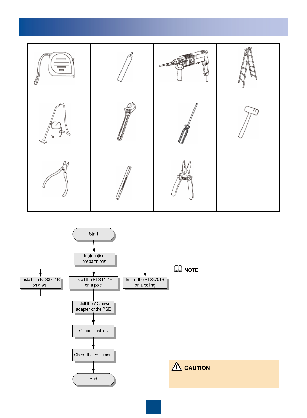
Installation ProcessInstallation Tools
zWhen an external antenna is used,
connect the antenna to the BTS3701B
before installing the BTS3701B.
zWhen the BTS3701B is installed on a
wall, the integrated mode is
recommended.
zThe BTS3701B must be installed at least
0.5 m (1'-7 11/16'') away from the
interference sources such as power
supply and at least 2 m (6'-6 3/4'') away
from the high frequency radiation
sources.
The BTS3701B cannot be placed horizontally
on a flat object, such as a table.
Measuring tape Marker Hammer drill Ladder
Vacuum cleaner Adjustable wrench Phillips screwdriver Rubber mallet
Diagonal pliers Level Wire stripper
3
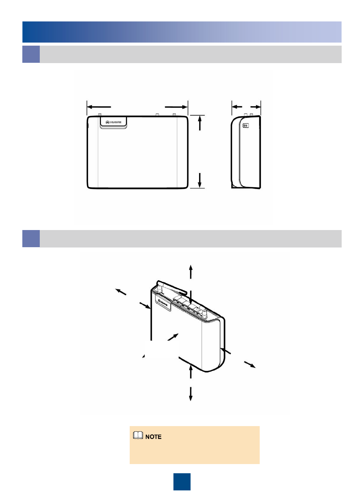
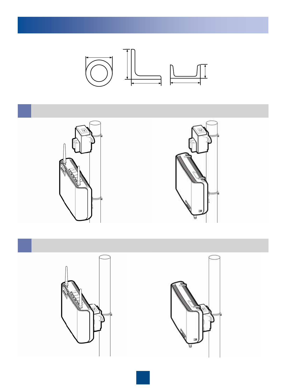
Minimum Space Requirements
Space Requirements
aDimensions of the BTS3701B
b
A minimum of 500 mm (1'-7 11/16'') should
be reserved at the back of the BTS3701B
only in the ceiling installation mode.
230 mm
(9 1/16'')
165 mm
(6 1/2'')
65 mm
(2 9/16'')
≥300 mm
(11 13/16'')
≥170 mm (6 11/16'')
≥100 mm
(3 15/16'')
≥250 mm
(9 13/16'')
≥250 mm
(9 13/16'')
4
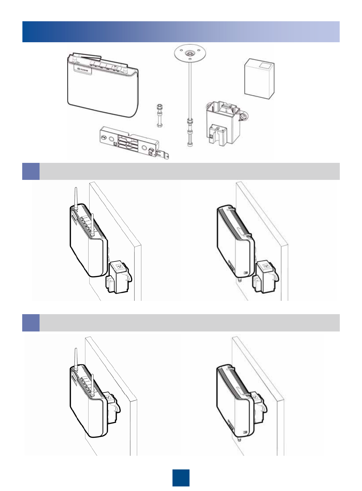
Installation Modes
Installing the BTS3701B on a Wall (Separated Mode)
a
bInstalling the BTS3701B on a Wall (Integrated Mode)
Regular installation Reverse installation
Regular installation Reverse installation
BTS3701B
Mounting bracket
for the module
Mounting bracket
for the adapter
Ceiling mounting
bracket
Transitional
piece
Adapter
5
Installation Modes
dInstalling the BTS3701B on a Pole (Integrated Mode)
Installing the BTS3701B on a Pole (Separated Mode)
c
Regular installation Reverse installation
Regular installation Reverse installation
The requirements for the installation carrier are as follows:
Pole Angle steel U-steel
20 mm (13/16'') to
85 mm (3 3/8'')
20 mm (13/16'') to
75 mm (2 15/16'')
20 mm
(13/16'') to 75
mm (2 15/16'')
20 mm (13/16'') to
65 mm (2 9/16'')
20 mm (13/16'') to
65 mm (2 9/16'')
6
Installation Modes
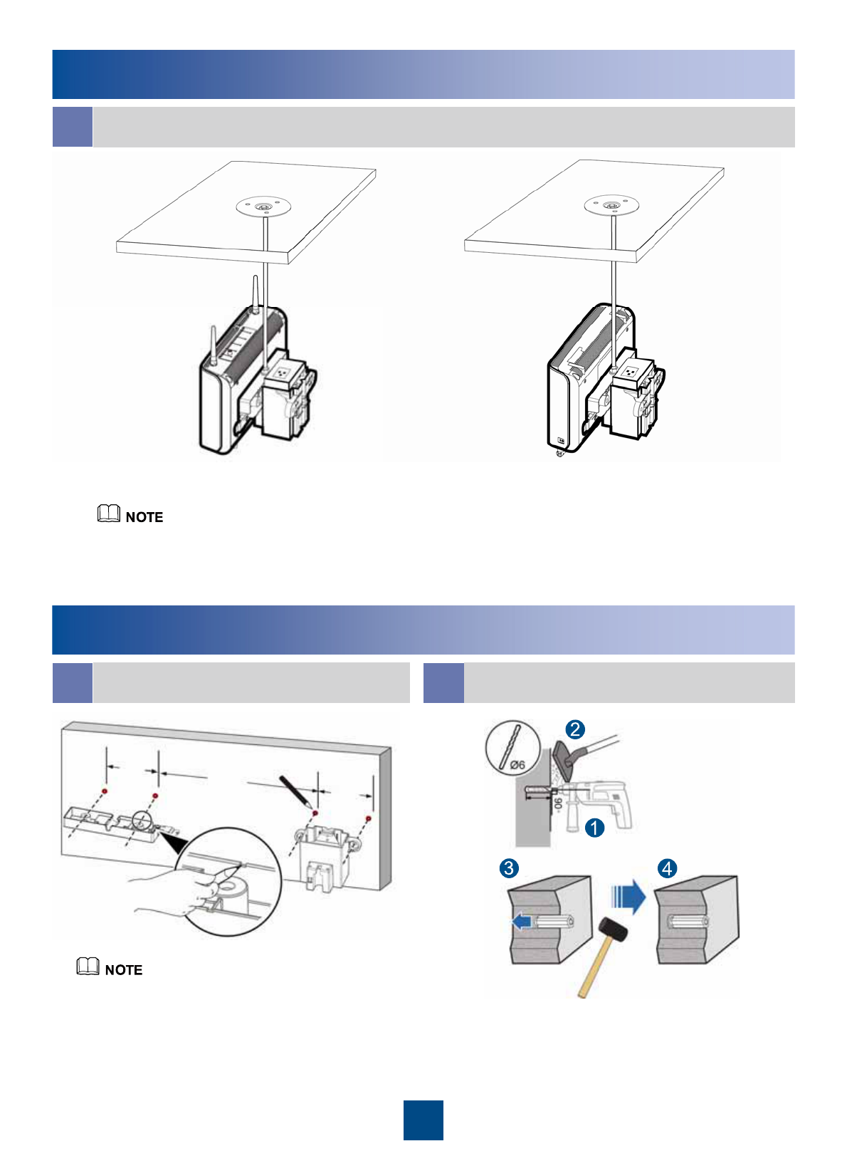
Installing the BTS3701B on a Ceiling
e
Regular installation Reverse installation
If the BTS3701B is installed on a ceiling, the ceiling must be made of
concrete and can bear a weight of 323.6 N.m (2864.10 lbf.in.).
Installing the BTS3701B on a Wall
aDetermining Installation Positions of the
Mounting Brackets bDrilling Holes and Installing Expansion Bolts
For the integrated installation mode, determine
only the installation position of the adapter.
88 mm (3 7/16'')
≥200 mm (7 7/8'')
88 mm
(3 7/16'')
24 mm (15/16'')
to 25 mm (1'')
7
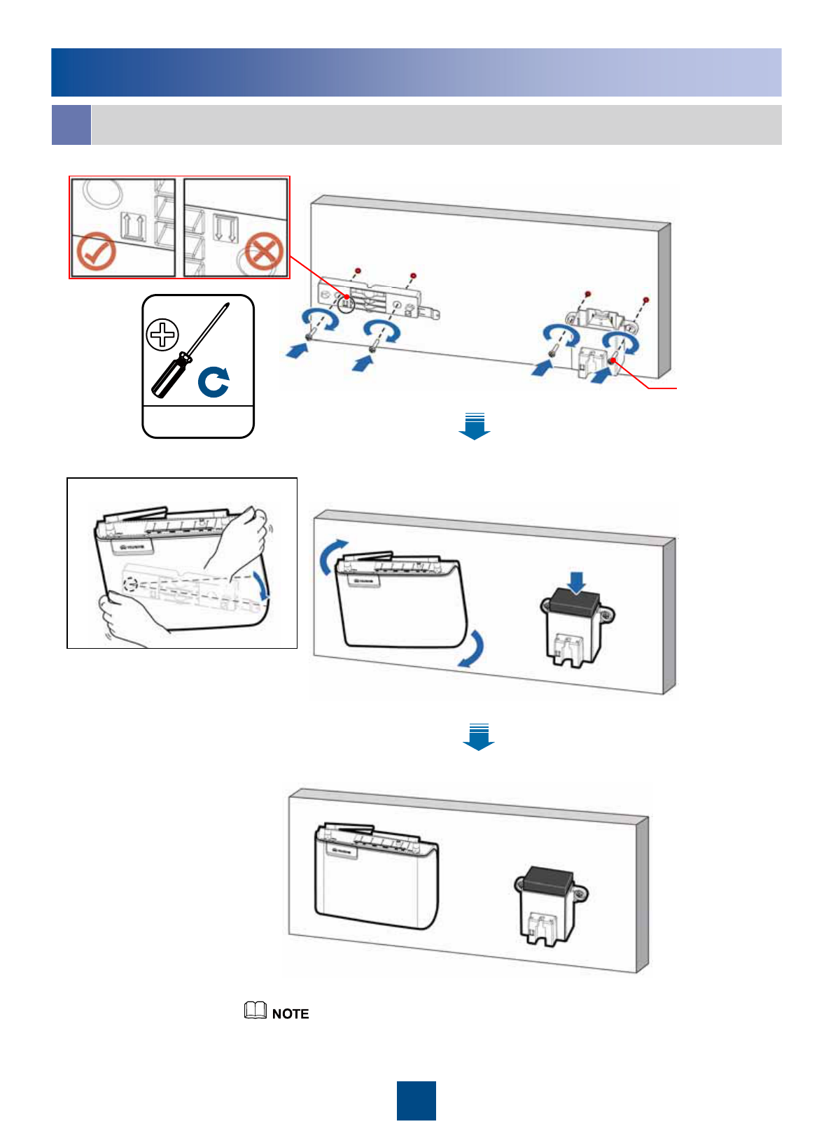
Installing the BTS3701B on a Wall
cSeparated Mode
3 ±0.5 N.m
(26.55 ±4.43 lbf.in.)
M4
The procedures of regular installation and reverse
installation are identical.
Installation procedure
M3.5×20
8
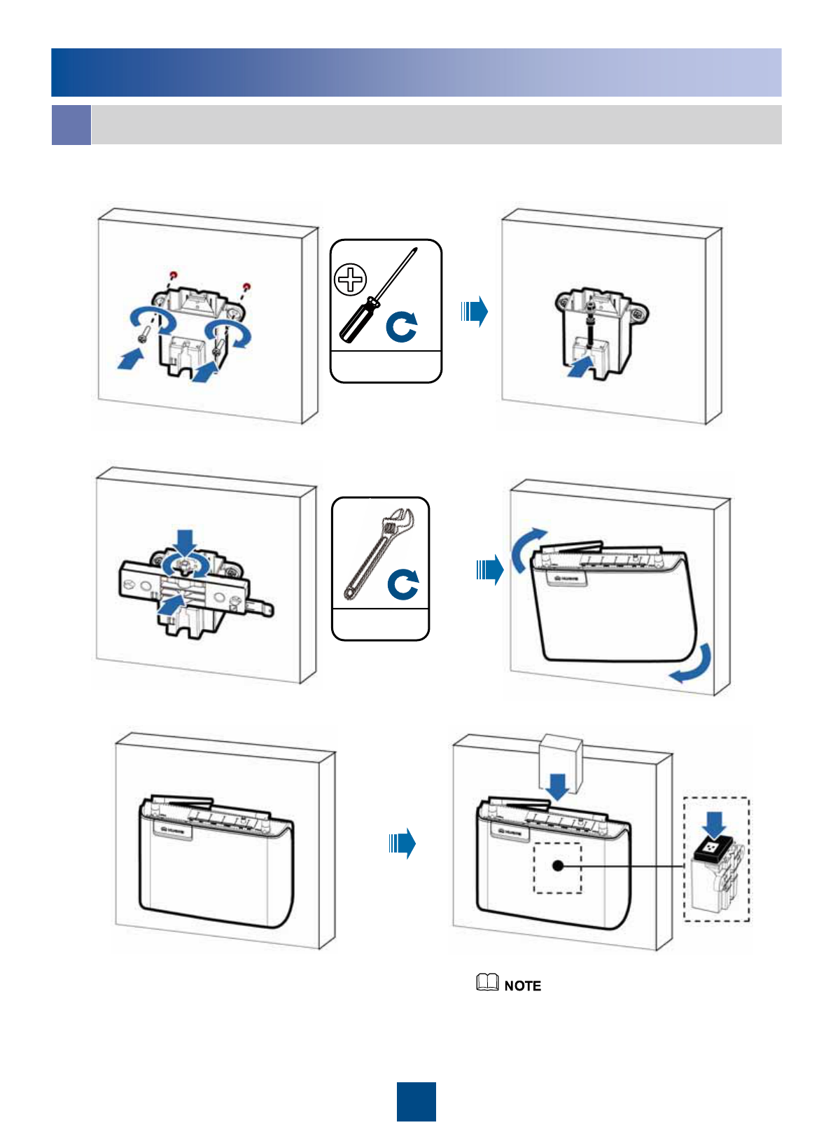
Integrated Mode
Installing the BTS3701B on a Wall
d
The procedures of regular installation and
reverse installation are identical.
3 ±0.5 N.m
(26.55 ±4.43 lbf.in.)
M4
10 N.m
(88.51 lbf.in.)
9
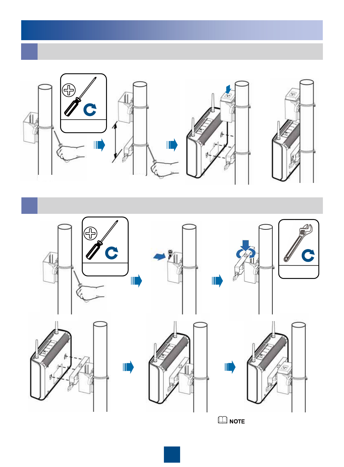
Installing the BTS3701B on a Pole
bIntegrated Mode
aSeparated Mode
≥300 mm
(11 13/16'')
The procedures of regular installation
and reverse installation are identical.
3 ±0.5 N.m
(26.55 ±4.43 lbf.in.)
M4
3 ±0.5 N.m
(26.55 ±4.43 lbf.in.)
M4
10 N.m
(88.51 lbf.in.)
10
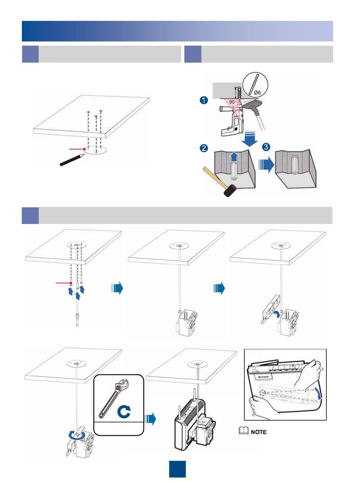
Installing the BTS3701B on a Ceiling
Installing the BTS3701B on a Ceiling
aDetermining Installation Positions of
Bolts bDrilling Holes and Installing
Expansion Bolts
c
The procedures of regular
installation and reverse installation
are identical.
Installation procedure
M3.5×20
Marking
template
24 mm
(15/16'') to
25 mm (1'')
10 N.m
(88.51 lbf.in.)
11
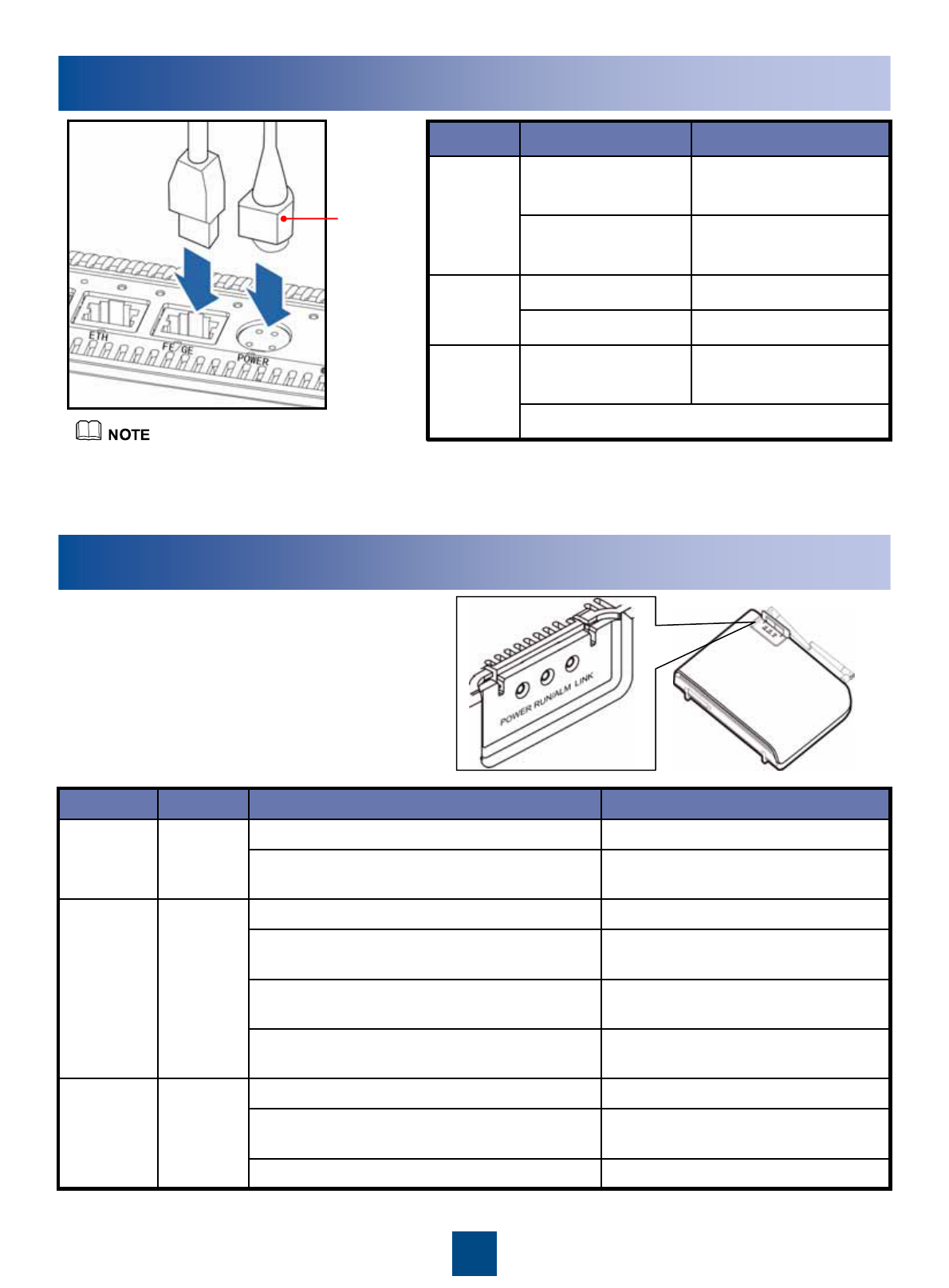
Connecting Cables
The other end is connected to the power adapter.
PWR port on the
BTS3701B
4-pin connector
DC input
power
cable
Connected to...ConnectorCable
Power adapterC7 female connector
AC power wiring bar PA male connector
Power
cable
Operator's transmission
equipment
RJ45 connector
FE/GE port on the
BTS3701B
RJ45 connector
Straight-
through
cable
If the delivered Ethernet cable [3 m (9'-10 1/8'')]
does not meet the requirement, prepare one
on site based on actual requirements.
4-pin
connector of
the DC input
power cable
Powering On the BTS3701B
Connect the PA male connector to
the AC power wiring bar to power on
the BTS3701B.
An alarm is generated, and the
BTS3701B needs to be replaced.
On (red)
The FE port is insecurely connected. Off
Data is being transmitted and
received over the FE port.
Blinking at 4 Hz (green) (on for 0.125s, off for
0.125s)
The FE port is securely connected. On GreenLINK
An alarm is generated. Rectify the
fault based on the reported alarm.
Blinking at 0.5 Hz (red) (on for 1s, off for 1s)
The BTS3701B is being loaded, or
the BTS3701B is not started.
Blinking at 4 Hz (green) (on for 0.125s, off for
0.125s)
The BTS3701B is running normally. Blinking at 0.5 Hz (green) (on for 1s, off for 1s)
Red and
green
RUN/ALM
There is no power supply, or the
BTS3701B is faulty.
Off
The power supply is normal. On GreenPower
DescriptionStatus ColorIndicator
12
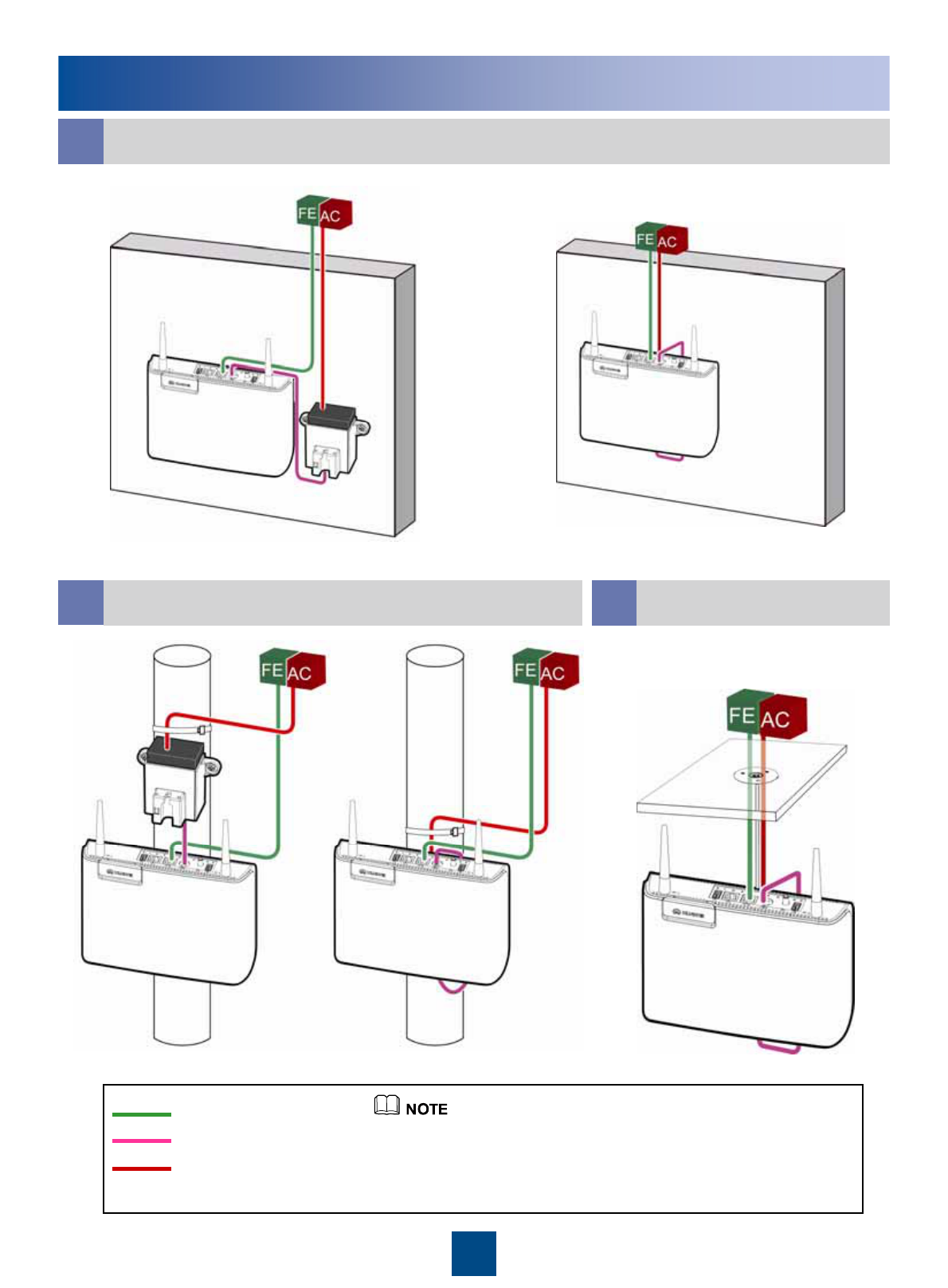
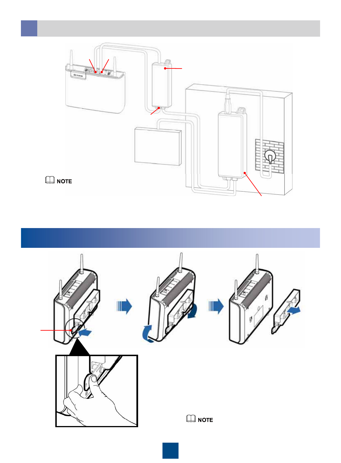
Appendix: Cabling Routes for Different Installation Modes
Straight-through cable
Power cable
DC input power cable zWhen the BTS3701B is installed on a pole, fix the input power
cable of the power adapter on the pole using a tie wrap.
zBefore powering on the equipment, ensure that the antenna of the
BTS3701B is vertical.
Installing the BTS3701B on a Wall
a
Installing the BTS3701B on a Pole
bc
Separated Mode Integrated Mode
Separated Mode Integrated Mode
Installing the BTS3701B
on a Ceiling
13
OUT IN
IN
OUT
FE/GE POWER
Powered device (PD)
Press the spring pad and rotate the
BTS3701B clockwise to remove it.
Appendix: Removing the Equipment
Spring
pad
Installing the External Equipment
e
The distance between the PSE and the PD
should be more than 1 m (3'-3 3/8''). The
PSE cannot be installed on a ceiling.
Network
equipment
Power sourcing equipment (PSE)

Huawei Technologies Co., Ltd.
Administration Building, Huawei Technologies
Co., Ltd., Bantian, Longgang District, Shenzhen,
P. R
Zip code: 518129
www.huawei.com