Huawei Technologies GRFU-1900 GSM Radio Frequency Unit User Manual Commissioning Guide
Huawei Technologies Co.,Ltd GSM Radio Frequency Unit Commissioning Guide
UserManual.wiki
>
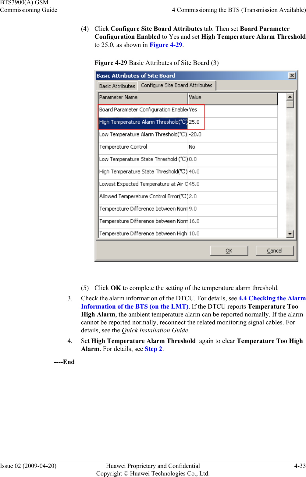
Huawei Technologies
>
GRFU 1900 User Manual
Installation Guide
Navigation menu
Upload a User Manual
Namespaces
Wiki Guide
HTML
PDF
Info
Views
User Manual
Discussion / Help
Navigation
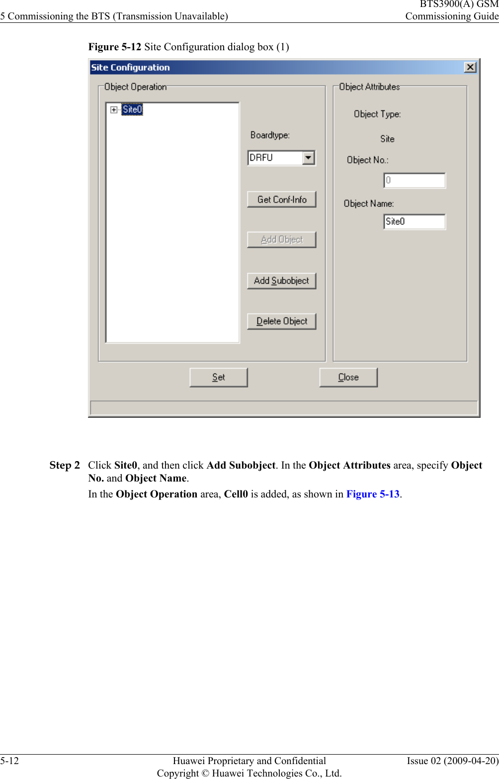
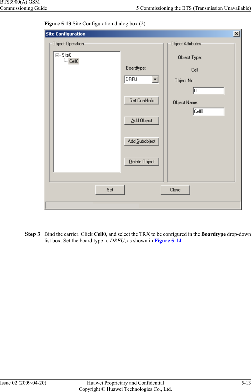
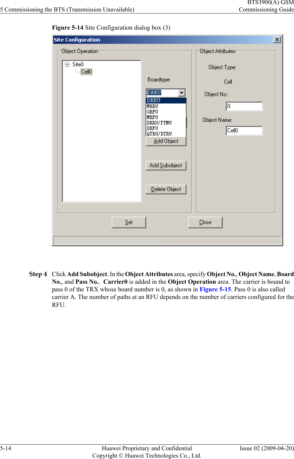
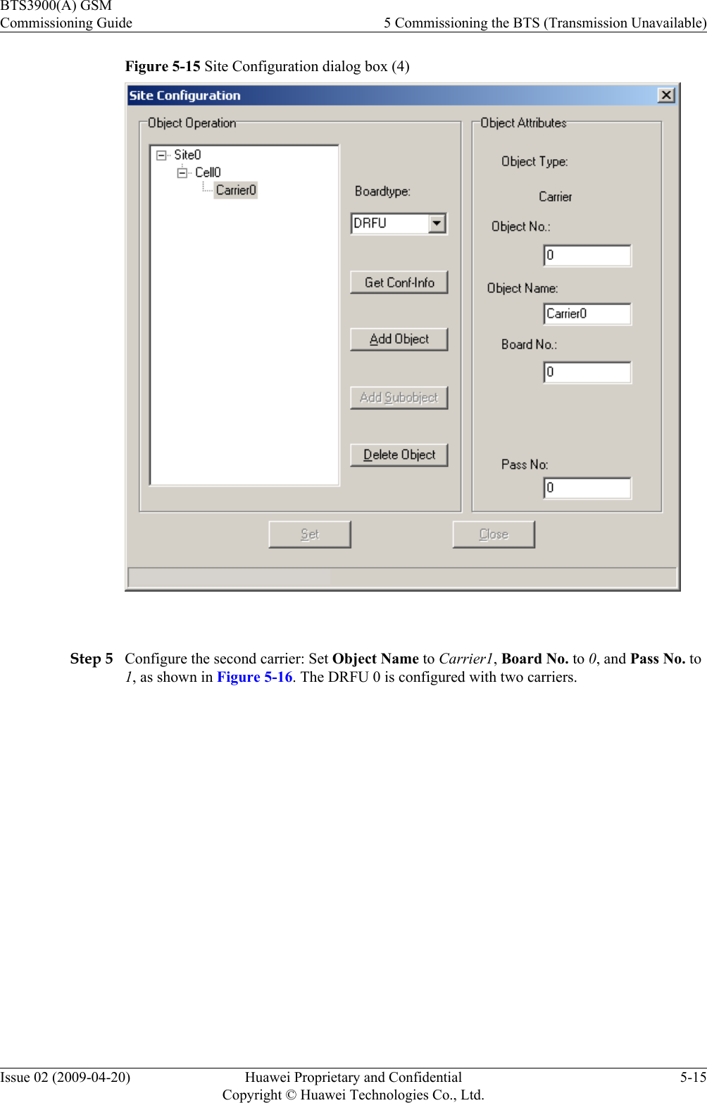
![The general conventions that may be found in this document are defined as follows.Convention DescriptionTimes New Roman Normal paragraphs are in Times New Roman.Boldface Names of files, directories, folders, and users are inboldface. For example, log in as user root.Italic Book titles are in italics.Courier New Examples of information displayed on the screen are inCourier New.Command ConventionsThe command conventions that may be found in this document are defined as follows.Convention DescriptionBoldface The keywords of a command line are in boldface.Italic Command arguments are in italics.[ ] Items (keywords or arguments) in brackets [ ] are optional.{ x | y | ... } Optional items are grouped in braces and separated byvertical bars. One item is selected.[ x | y | ... ] Optional items are grouped in brackets and separated byvertical bars. One item is selected or no item is selected.{ x | y | ... }*Optional items are grouped in braces and separated byvertical bars. A minimum of one item or a maximum of allitems can be selected.[ x | y | ... ]*Optional items are grouped in brackets and separated byvertical bars. Several items or no item can be selected.GUI ConventionsThe GUI conventions that may be found in this document are defined as follows.Convention DescriptionBoldface Buttons, menus, parameters, tabs, window, and dialog titlesare in boldface. For example, click OK.>Multi-level menus are in boldface and separated by the ">"signs. For example, choose File > Create > Folder .Keyboard OperationsThe keyboard operations that may be found in this document are defined as follows.BTS3900(A) GSMCommissioning Guide About This DocumentIssue 02 (2009-04-20) Huawei Proprietary and ConfidentialCopyright © Huawei Technologies Co., Ltd.3](https://usermanual.wiki/Huawei-Technologies/GRFU-1900/User-Guide-1349794-Page-13.png)