Huawei Technologies GRFU-1900 GSM Radio Frequency Unit User Manual Commissioning Guide
Huawei Technologies Co.,Ltd GSM Radio Frequency Unit Commissioning Guide
Installation Guide

BTS3900(A) GSM
V300R008
Commissioning Guide
Issue 02
Date 2009-04-20
Huawei Proprietary and Confidential
Copyright © Huawei Technologies Co., Ltd.

Huawei Technologies Co., Ltd. provides customers with comprehensive technical support and service. For any
assistance, please contact our local office or company headquarters.
Huawei Technologies Co., Ltd.
Address: Huawei Industrial Base
Bantian, Longgang
Shenzhen 518129
People's Republic of China
Website: http://www.huawei.com
Email: support@huawei.com
Copyright © Huawei Technologies Co., Ltd. 2009. All rights reserved.
No part of this document may be reproduced or transmitted in any form or by any means without prior written
consent of Huawei Technologies Co., Ltd.
Trademarks and Permissions
and other Huawei trademarks are the property of Huawei Technologies Co., Ltd.
All other trademarks and trade names mentioned in this document are the property of their respective holders.
Notice
The information in this document is subject to change without notice. Every effort has been made in the
preparation of this document to ensure accuracy of the contents, but the statements, information, and
recommendations in this document do not constitute a warranty of any kind, express or implied.
Huawei Proprietary and Confidential
Copyright © Huawei Technologies Co., Ltd.

Contents
About This Document.....................................................................................................................1
1 Changes in BTS3900(A) GSM Commissioning Guide.......................................................1-1
2 General Requirements for the Commissioning...................................................................2-1
2.1 Commissioning Resources..............................................................................................................................2-2
2.2 Commissioning Prerequisites..........................................................................................................................2-3
3 Commissioning Procedure.......................................................................................................3-1
4 Commissioning the BTS (Transmission Available)............................................................4-1
4.1 Starting the LMT.............................................................................................................................................4-2
4.2 Checking the Transmission and Networking..................................................................................................4-4
4.2.1 Checking the Transmission Between the RRU and the BBU or Between the BBU and the BSC on the
LMT................................................................................................................................................................4-5
4.2.2 Checking the Transmission Between Cascaded BTSs...........................................................................4-6
4.2.3 Checking the Transmission Between BTSs in Ring Topology..............................................................4-8
4.3 Checking Software Version and Data Configuration....................................................................................4-11
4.3.1 Checking the Board Configuration and Status on the LMT.................................................................4-11
4.3.2 Checking the Current Software Version on the LMT..........................................................................4-13
4.3.3 Checking the Consistency Between Hardware Installation and Data Configuration...........................4-14
4.4 Checking the Alarm Information of the BTS (on the LMT).........................................................................4-19
4.5 Commissioning the BTS Services.................................................................................................................4-22
4.5.1 Testing the CS Services........................................................................................................................4-23
4.5.2 Commissioning PS Services.................................................................................................................4-25
4.6 Checking the BTS Environment Alarms.......................................................................................................4-26
4.6.1 BTS Environment Alarm Types...........................................................................................................4-26
4.6.2 Checking the Environment Monitoring Alarms on the LMT..............................................................4-28
5 Commissioning the BTS (Transmission Unavailable).......................................................5-1
5.1 Starting the Site Maintenance Terminal..........................................................................................................5-2
5.1.1 Setting the IP Address of the Site Maintenance Terminal PC...............................................................5-2
5.1.2 Locally Connecting the SMT PC to the BTS.........................................................................................5-3
5.1.3 Logging in to the BTS at the Local End.................................................................................................5-3
5.2 Configuring the Basic Data of the BTS..........................................................................................................5-5
5.2.1 Obtaining the Site Management Rights.................................................................................................5-6
BTS3900(A) GSM
Commissioning Guide Contents
Issue 02 (2009-04-20) Huawei Proprietary and Confidential
Copyright © Huawei Technologies Co., Ltd.
i

5.2.2 Configuring the Boards of the BTS on the SMT...................................................................................5-7
5.2.3 Configuring Logical Objects of the BTS on the SMT.........................................................................5-11
5.3 Checking the Active Software Version on the SMT.....................................................................................5-23
5.4 Checking the Transmission Between the BBU and RFU on the BTS Side..................................................5-25
5.5 Checking the Running Status of the BTS......................................................................................................5-26
5.5.1 Checking the State of the BTS LEDs...................................................................................................5-26
5.5.2 Checking the Alarm Information of the BTS on the SMT...................................................................5-29
5.6 Checking the Hardware Connection of the BTS...........................................................................................5-32
6 Optional Commissioning Tasks..............................................................................................6-1
6.1 Commissioning the Antenna System..............................................................................................................6-2
6.1.1 Measuring the VSWR............................................................................................................................6-2
6.1.2 Monitoring the Output Power of TRXs..................................................................................................6-3
6.1.3 Checking the Antenna Connection.........................................................................................................6-5
6.2 Performing the Loopback Test........................................................................................................................6-6
6.2.1 Performing the Carrier Loopback Test...................................................................................................6-6
6.2.2 Performing Channel Loopback Tests.....................................................................................................6-8
6.3 Checking the DIP Switch Settings of the Boards............................................................................................6-9
6.4 Locally Checking the Transmission Between the BBU and the BSC...........................................................6-10
6.5 Checking the Transmission Between Cascaded TRXs.................................................................................6-12
6.6 Checking TRXs in Ring Topology................................................................................................................6-14
7 FAQs for BTS Commissioning................................................................................................7-1
7.1 Failed Communication Between the SMT and the BTS.................................................................................7-2
7.2 Faulty E1 Link.................................................................................................................................................7-2
7.3 Failure of an MS to Search the Network.........................................................................................................7-6
7.4 Service Dialing Failure....................................................................................................................................7-7
7.5 Low GPRS Data Transmission Rate...............................................................................................................7-7
8 Commissioning Record Data Sheet........................................................................................8-1
9 Communication Ports Used by the GBTS.............................................................................9-1
Contents
BTS3900(A) GSM
Commissioning Guide
ii Huawei Proprietary and Confidential
Copyright © Huawei Technologies Co., Ltd.
Issue 02 (2009-04-20)

Figures
Figure 3-1 Commissioning procedure (transmission available)...........................................................................3-2
Figure 3-2 Commissioning procedure (transmission unavailable).......................................................................3-4
Figure 4-1 Login dialog box of the BSC6000 Local Maintenance Terminal.......................................................4-2
Figure 4-2 BSC Management dialog box ............................................................................................................4-3
Figure 4-3 Login dialog box of the M2000 client................................................................................................4-3
Figure 4-4 iManager M2000 Mobile Element Management System window ....................................................4-4
Figure 4-5 Check whether the link between the BBU and the BSC is normal....................................................4-6
Figure 4-6 Check whether the link between the BBU and the RFU is normal....................................................4-6
Figure 4-7 Cascaded BTSs on the LMT...............................................................................................................4-7
Figure 4-8 Site Device Panel tab page.................................................................................................................4-8
Figure 4-9 Connection between ring topology BTSs...........................................................................................4-9
Figure 4-10 Maintain Ring Network dialog box..................................................................................................4-9
Figure 4-11 Confirm dialog box.........................................................................................................................4-10
Figure 4-12 Result of the ring topology switchover (1).....................................................................................4-10
Figure 4-13 Result of the ring topology switchover (2).....................................................................................4-10
Figure 4-14 Site Device Panel tab page.............................................................................................................4-12
Figure 4-15 Query Board Information dialog box.............................................................................................4-13
Figure 4-16 Query Board Running Software Version dialog box ....................................................................4-14
Figure 4-17 Relation between data configuration and physical connection of the BTS3900 monitoring boards
.............................................................................................................................................................................4-15
Figure 4-18 Relation between data configuration and physical connection of the BTS3900A monitoring boards
.............................................................................................................................................................................4-16
Figure 4-19 Site Device Panel tab page.............................................................................................................4-17
Figure 4-20 Query Board Information dialog box.............................................................................................4-18
Figure 4-21 Site Device Panel tab page.............................................................................................................4-20
Figure 4-22 Filter Alarm Condition dialog box.................................................................................................4-21
Figure 4-23 Alarm Detail Information dialog box.............................................................................................4-21
Figure 4-24 BSS Help System...........................................................................................................................4-22
Figure 4-25 Modify Administrative State dialog box........................................................................................4-24
Figure 4-26 Basic Attributes of Site Board (1)..................................................................................................4-30
Figure 4-27 Basic Attributes of Site Board (2)..................................................................................................4-31
Figure 4-28 Query Board Information dialog box.............................................................................................4-32
Figure 4-29 Basic Attributes of Site Board (3)..................................................................................................4-33
Figure 5-1 Site Maintenance Terminal system window.......................................................................................5-4
BTS3900(A) GSM
Commissioning Guide Figures
Issue 02 (2009-04-20) Huawei Proprietary and Confidential
Copyright © Huawei Technologies Co., Ltd.
iii

Figure 5-2 Communication failed dialog box...................................................................................................... 5-4
Figure 5-3 Set Communication Port Parameter dialog box................................................................................. 5-5
Figure 5-4 Warning message for obtaining the site management right................................................................5-6
Figure 5-5 Site Management Right dialog box....................................................................................................5-6
Figure 5-6 Board Configuration window.......................................................................................................... 5-8
Figure 5-7 Topology Configuration window.....................................................................................................5-8
Figure 5-8 Deploy DRRU dialog box ................................................................................................................. 5-9
Figure 5-9 Topology Configuration window....................................................................................................... 5-9
Figure 5-10 Board Configuration window ........................................................................................................5-10
Figure 5-11 Parameter Management dialog box.............................................................................................5-11
Figure 5-12 Site Configuration dialog box (1)...................................................................................................5-12
Figure 5-13 Site Configuration dialog box (2)...................................................................................................5-13
Figure 5-14 Site Configuration dialog box (3)...................................................................................................5-14
Figure 5-15 Site Configuration dialog box (4)...................................................................................................5-15
Figure 5-16 Site Configuration dialog box (5)...................................................................................................5-16
Figure 5-17 User Error dialog box.....................................................................................................................5-17
Figure 5-18 Site Configuration dialog box (6)...................................................................................................5-18
Figure 5-19 Configured cell and channels..........................................................................................................5-19
Figure 5-20 Site Opstart dialog box...................................................................................................................5-20
Figure 5-21 Cell Opstart dialog box...................................................................................................................5-20
Figure 5-22 BT Opstart dialog box....................................................................................................................5-21
Figure 5-23 RC Attributes Management dialog box..........................................................................................5-21
Figure 5-24 RC Opstart successfully dialog box................................................................................................5-22
Figure 5-25 Board Management window...........................................................................................................5-22
Figure 5-26 Board Management window (1).....................................................................................................5-23
Figure 5-27 Topology Management window.....................................................................................................5-24
Figure 5-28 Board Information dialog box (1) ..................................................................................................5-24
Figure 5-29 Board Information dialog box (2)...................................................................................................5-25
Figure 5-30 Board Management window ..........................................................................................................5-30
Figure 5-31 Topology Management window.....................................................................................................5-31
Figure 5-32 Board Alarm Information dialog box.............................................................................................5-31
Figure 6-1 Please select RC to test dialog box.....................................................................................................6-3
Figure 6-2 RF Performance Test dialog box........................................................................................................6-3
Figure 6-3 Test TRX Loopback dialog box......................................................................................................... 6-7
Figure 6-4 Test Channel Loopback dialog box....................................................................................................6-8
Figure 6-5 Site Device Attributes dialog box.....................................................................................................6-10
Figure 6-6 Physical loopback of E1/T1 at the DDF...........................................................................................6-12
Figure 6-7 Site Device Panel tab page...............................................................................................................6-13
Figure 6-8 Connection between TRXs in ring topology....................................................................................6-14
Figure 6-9 Site Device Attributes dialog box.....................................................................................................6-15
Figure 6-10 Set RXU Chain Break Point dialog box.........................................................................................6-16
Figure 6-11 Setting breakpoint successfully......................................................................................................6-16
Figures
BTS3900(A) GSM
Commissioning Guide
iv Huawei Proprietary and Confidential
Copyright © Huawei Technologies Co., Ltd.
Issue 02 (2009-04-20)

Figure 6-12 Status of the disconnected TRX ring topology...............................................................................6-17
Figure 6-13 Split RXU Chain dialog box...........................................................................................................6-17
Figure 6-14 Splitting RXU chain successfully...................................................................................................6-18
Figure 6-15 TRX ring topology in splitting state...............................................................................................6-18
Figure 6-16 Combine RXU Chain dialog box....................................................................................................6-19
Figure 6-17 Combining RXU chain successfully...............................................................................................6-20
Figure 6-18 RXU ring in combined state...........................................................................................................6-21
Figure 6-19 RXU Ring in normal state..............................................................................................................6-22
Figure 7-1 Crossed pair connection......................................................................................................................7-3
Figure 7-2 E1 link between the BTS and the BSC (1).........................................................................................7-3
Figure 7-3 E1 link between the BTS and the BSC (2).........................................................................................7-4
Figure 7-4 Physical loopback of E1/T1 on the BTS side.....................................................................................7-5
BTS3900(A) GSM
Commissioning Guide Figures
Issue 02 (2009-04-20) Huawei Proprietary and Confidential
Copyright © Huawei Technologies Co., Ltd.
v

Tables
Table 2-1 Tools required for the commissioning of the BTS3900/BTS3900A...................................................2-2
Table 3-1 Commissioning procedure (transmission available)............................................................................3-2
Table 3-2 Commissioning procedure (transmission unavailable)........................................................................3-5
Table 4-1 Monitoring boards of the BTS3900 and the BTS3900A...................................................................4-28
Table 5-1 TRX types configured on the BTS3900 GSM or the BTS3900A GSM..............................................5-7
Table 5-2 Normal states of the LEDs on the board and modules in the BBU....................................................5-27
Table 5-3 Normal states of the LEDs on the DRFU...........................................................................................5-27
Table 5-4 Normal states of the LEDs on the GATM.........................................................................................5-28
Table 5-5 Normal states of the LEDs on the FAN unit......................................................................................5-28
Table 5-6 Normal states of the LEDs on the PMU.............................................................................................5-28
Table 5-7 Normal states of the LEDs on the PSU..............................................................................................5-29
Table 5-8 Checklist for the connection of the power cables and grounding cables...........................................5-32
Table 5-9 Checklist for the connection of the signal cables...............................................................................5-33
Table 6-1 Parameter required in RF performance test..........................................................................................6-4
Table 7-1 Possible causes and handling suggestions for failed communication between the SMT and the BTS
...............................................................................................................................................................................7-2
Table 7-2 Meaning of the state of the LIU LEDs (UELP used)..........................................................................7-5
Table 7-3 Meaning of the state of the LIU LEDs (UELP not used)....................................................................7-6
Table 7-4 Possible causes and handling suggestions for service dialing failure..................................................7-7
Table 7-5 Description of the DIP switch SW2 on the GTMU.............................................................................7-7
Table 8-1 Data sheet for BTS commissioning......................................................................................................8-1
Table 9-1 The Communication Port Used by GBTS............................................................................................9-1
BTS3900(A) GSM
Commissioning Guide Tables
Issue 02 (2009-04-20) Huawei Proprietary and Confidential
Copyright © Huawei Technologies Co., Ltd.
vii
About This Document
Overview
This document describes the procedures for commissioning and verifying the BTS3900/
BTS3900A GSM after it is installed. The commissioning and verification procedures ensure that
the BTS3900/BTS3900A GSM operates as required. The BTS3900/BTS3900A commissioning
scenarios include the transmission available scenario and transmission unavailable scenario.
Version
The following table lists the product versions related to this document.
Product Name Version
BTS3900 GSM (hereinafter referred to
as BTS3900)
V300R008
BTS3900A GSM (hereinafter referred to
as BTS3900A)
V300R008
Intended Audience
This document is intended for:
lField engineers
lTechnical support engineers
Organization
1 Changes in BTS3900(A) GSM Commissioning Guide
This describes the changes in the “BTS3900(A) GSM Commissioning Guide”.
2 General Requirements for the Commissioning
The general requirements for the commissioning are the commissioning prerequisites and
commissioning resources.
3 Commissioning Procedure
This describes the commissioning procedure of the BTS. According to the transmission situation
between the BSC and BTS, the commissioning procedure of the BTS can be classified into two
types: commissioning procedure in transmission available scenario and commissioning
procedure in transmission unavailable scenario.
BTS3900(A) GSM
Commissioning Guide About This Document
Issue 02 (2009-04-20) Huawei Proprietary and Confidential
Copyright © Huawei Technologies Co., Ltd.
1
4 Commissioning the BTS (Transmission Available)
This describes how to commission the BTS when the transmission cable between the BSC and
the BTS is properly connected.
5 Commissioning the BTS (Transmission Unavailable)
This describes how to commission the BTS in the transmission unavailable scenario. The
commissioning of the BTS consists of two phases. In the initial phase of the commissioning, the
transmission cable between the BSC and the BTS is not properly connected. Commission the
BTS at the local end. In the later phase of the commissioning, the transmission cable between
the BSC and the BTS is properly connected. Commission the BTS on the BSC side.
6 Optional Commissioning Tasks
The optional commissioning tasks are the VSWR check, output power of the TRX check,
loopback test check, settings of the DIP switches on the board check, transmission between the
BBU and the BSC on the BTS side check, transmission between cascaded TRXs check, and
TRX ring topology check.
7 FAQs for BTS Commissioning
This describes the fault symptoms and cause analysis in the BTS commissioning.
8 Commissioning Record Data Sheet
This describes the data sheet that is used to record the process and result of the BTS
commissioning.
9 Communication Ports Used by the GBTS
Conventions
Symbol Conventions
The symbols that may be found in this document are defined as follows.
Symbol Description
Indicates a hazard with a high level of risk, which if not
avoided,will result in death or serious injury.
Indicates a hazard with a medium or low level of risk, which
if not avoided, could result in minor or moderate injury.
Indicates a potentially hazardous situation, which if not
avoided,could result in equipment damage, data loss,
performance degradation, or unexpected results.
Indicates a tip that may help you solve a problem or save
time.
Provides additional information to emphasize or supplement
important points of the main text.
General Conventions
About This Document
BTS3900(A) GSM
Commissioning Guide
2 Huawei Proprietary and Confidential
Copyright © Huawei Technologies Co., Ltd.
Issue 02 (2009-04-20)
The general conventions that may be found in this document are defined as follows.
Convention Description
Times New Roman Normal paragraphs are in Times New Roman.
Boldface Names of files, directories, folders, and users are in
boldface. For example, log in as user root.
Italic Book titles are in italics.
Courier New Examples of information displayed on the screen are in
Courier New.
Command Conventions
The command conventions that may be found in this document are defined as follows.
Convention Description
Boldface The keywords of a command line are in boldface.
Italic Command arguments are in italics.
[ ] Items (keywords or arguments) in brackets [ ] are optional.
{ x | y | ... } Optional items are grouped in braces and separated by
vertical bars. One item is selected.
[ x | y | ... ] Optional items are grouped in brackets and separated by
vertical bars. One item is selected or no item is selected.
{ x | y | ... }*Optional items are grouped in braces and separated by
vertical bars. A minimum of one item or a maximum of all
items can be selected.
[ x | y | ... ]*Optional items are grouped in brackets and separated by
vertical bars. Several items or no item can be selected.
GUI Conventions
The GUI conventions that may be found in this document are defined as follows.
Convention Description
Boldface Buttons, menus, parameters, tabs, window, and dialog titles
are in boldface. For example, click OK.
>Multi-level menus are in boldface and separated by the ">"
signs. For example, choose File > Create > Folder .
Keyboard Operations
The keyboard operations that may be found in this document are defined as follows.
BTS3900(A) GSM
Commissioning Guide About This Document
Issue 02 (2009-04-20) Huawei Proprietary and Confidential
Copyright © Huawei Technologies Co., Ltd.
3
Format Description
Key Press the key. For example, press Enter and press Tab.
Key 1+Key 2 Press the keys concurrently. For example, pressing Ctrl+Alt
+A means the three keys should be pressed concurrently.
Key 1, Key 2 Press the keys in turn. For example, pressing Alt, A means
the two keys should be pressed in turn.
Mouse Operations
The mouse operations that may be found in this document are defined as follows.
Action Description
Click Select and release the primary mouse button without moving
the pointer.
Double-click Press the primary mouse button twice continuously and
quickly without moving the pointer.
Drag Press and hold the primary mouse button and move the
pointer to a certain position.
About This Document
BTS3900(A) GSM
Commissioning Guide
4 Huawei Proprietary and Confidential
Copyright © Huawei Technologies Co., Ltd.
Issue 02 (2009-04-20)

1 Changes in BTS3900(A) GSM
Commissioning Guide
This describes the changes in the “BTS3900(A) GSM Commissioning Guide”.
02(2009-04-20)
Second commercial release
Compared with issue 01 (2009-02-16) of V300R008, no contents are deleted. The changes are
as follows:
The solution to trouble is added. For details, see 5.2.3 Configuring Logical Objects of the BTS
on the SMT, 4.2.3 Checking the Transmission Between BTSs in Ring Topology, 4.2.1
Checking the Transmission Between the RRU and the BBU or Between the BBU and the
BSC on the LMT and 5.2.1 Obtaining the Site Management Rights.
01 (2009-02-16)
Initial commercial release
BTS3900(A) GSM
Commissioning Guide 1 Changes in BTS3900(A) GSM Commissioning Guide
Issue 02 (2009-04-20) Huawei Proprietary and Confidential
Copyright © Huawei Technologies Co., Ltd.
1-1

2 General Requirements for the
Commissioning
About This Chapter
The general requirements for the commissioning are the commissioning prerequisites and
commissioning resources.
2.1 Commissioning Resources
Before the commissioning, you must arrange for the tools, obtain the information about the site
to be commissioned, and download the correct software for the boards in the BTS3900/
BTS3900A.
2.2 Commissioning Prerequisites
Before the commissioning, you must check the operating status of the BTS3900/BTS3900A and
BSC.
BTS3900(A) GSM
Commissioning Guide 2 General Requirements for the Commissioning
Issue 02 (2009-04-20) Huawei Proprietary and Confidential
Copyright © Huawei Technologies Co., Ltd.
2-1
2.1 Commissioning Resources
Before the commissioning, you must arrange for the tools, obtain the information about the site
to be commissioned, and download the correct software for the boards in the BTS3900/
BTS3900A.
Tools
Table 2-1 describes the tools and instruments required for the commissioning.
Table 2-1 Tools required for the commissioning of the BTS3900/BTS3900A
Tools Qua
ntity
Specification
PC 1 Optional. The PC is used for the commissioning on
the BTS side when the transmission between the BSC
and BTS is unavailable. For details on the
configuration, see Configuration Requirements
for the Site Maintenance Terminal PC.
For details on how to install and use the SMT
application, see BTS3900A GSM Site Maintenance
Terminal User Guide.
Multimeter 1 Mandatory
Power Meter 1 Mandatory. The power meter is used to measure the
output power of TRXs.
Site Master 1 Mandatory. The Site Master is used to measure the
VSWR.
GSM MSs for testing 2 Mandatory. The MSs are used for the BTS service
commissioning and antenna system commissioning.
The requirements for the GSM MS for testing are as
follows:
lThe UE is configured with the SIM card.
lThe MS is registered with the HLR on the network.
Ethernet cable 1 Optional. The Ethernet cable is used to connect the
SMT PC to the BBU when the transmission is
unavailable.
NOTE
If the SMT PC is installed with the windows 98 operating
system, the type of the Ethernet cables should be crossover
cable.
2 General Requirements for the Commissioning
BTS3900(A) GSM
Commissioning Guide
2-2 Huawei Proprietary and Confidential
Copyright © Huawei Technologies Co., Ltd.
Issue 02 (2009-04-20)
Tools Qua
ntity
Specification
Serial port cable 1 Optional. The serial port cable is used when you
query the IP address of the board on the BTS side.
The auxiliary cables are listed as follows:
lOne commissioning cable connected to the serial
Ethernet port
lOne extended serial port cable
Flat-head screwdriver 1 Optional. The flat-head screwdriver is used to
remove the Ethernet cable when the transmission
between the BSC and the BTS is unavailable.
When removing the Ethernet port, you must use a
flat-head screwdriver to press the RJ45 connector
and then remove the RJ45 connector.
Light emitting diode (LED) 2 Optional. The LEDs are used to determine the RX or
TX end of the E1 line.
Information About the Base Station
Before the commissioning, you must obtain the following information about the base station:
lInformation on BTS networking and related configuration, including the BTS type,
transmission mode, networking mode, and cell configuration.
lBTS3900/BTS3900A data configured on the BSC side.
Board Software
When the transmission is unavailable, download the matching software for the boards to the
SMT PC before the commissioning.
The software for the boards in the BTS3900/BTS3900A is as follows:
lRFU software
lGTMU software
lGATM software
lPMU software
2.2 Commissioning Prerequisites
Before the commissioning, you must check the operating status of the BTS3900/BTS3900A and
BSC.
Hardware Requirements
lThe BTS3900/BTS3900A cabinet is installed and the cables are connected.
lThe BTS3900/BTS3900A has passed the hardware installation check before it is powered
on.
BTS3900(A) GSM
Commissioning Guide 2 General Requirements for the Commissioning
Issue 02 (2009-04-20) Huawei Proprietary and Confidential
Copyright © Huawei Technologies Co., Ltd.
2-3

lThe BTS3900/BTS3900A is powered on. For details, see Powering On the BTS3900A or
Powering On the BTS3900.
lThe BSC is installed. The system commissioning is complete, and the system is running
normally.
Software Requirements
lThe data of the BTS3900/BTS3900A is configured on the BSC.
2 General Requirements for the Commissioning
BTS3900(A) GSM
Commissioning Guide
2-4 Huawei Proprietary and Confidential
Copyright © Huawei Technologies Co., Ltd.
Issue 02 (2009-04-20)

3 Commissioning Procedure
This describes the commissioning procedure of the BTS. According to the transmission situation
between the BSC and BTS, the commissioning procedure of the BTS can be classified into two
types: commissioning procedure in transmission available scenario and commissioning
procedure in transmission unavailable scenario.
Context
lTo solve common problems that occur during the commissioning, see 7 FAQs for BTS
Commissioning.
lIn this document, RFUs are classified into two types: DRFUs and GRFUs.
Procedure
lCommissioning procedure in transmission available scenario
In the transmission available scenario, the transmission cables between the BSC and the
BTS are properly connected before the commissioning. Generally, the commissioning is
performed on the BSC6000 LMT. If the commissioning can not be performed on the LMT
independently, contact engineers on the BTS side to perform the commissioning task.
BTS3900(A) GSM
Commissioning Guide 3 Commissioning Procedure
Issue 02 (2009-04-20) Huawei Proprietary and Confidential
Copyright © Huawei Technologies Co., Ltd.
3-1
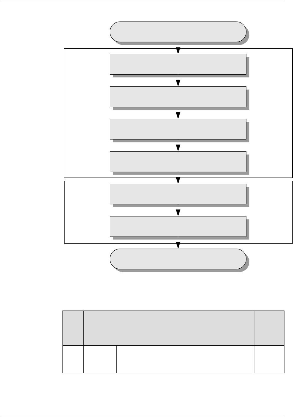
Figure 3-1 Commissioning procedure (transmission available)
Remote
operation
Cooperation of
local and
remote operation
Run
Run the BSC LMT
Check the software version
and the data configuration
Check the alarm information of the BTS
Commission the BTS services
Check the BTS environment alarms
End
Check the Transmission and Networking
Table 3-1 Commissioning procedure (transmission available)
No. Operation Procedure Mandat
ory/
Optiona
l
1Operation
on the
BSC LMT
Run the BSC LMT software. For details, see 4.1
Starting the LMT.
Mandato
ry
3 Commissioning Procedure
BTS3900(A) GSM
Commissioning Guide
3-2 Huawei Proprietary and Confidential
Copyright © Huawei Technologies Co., Ltd.
Issue 02 (2009-04-20)

No. Operation Procedure Mandat
ory/
Optiona
l
2Check the transmission and networking to ensure that
the transmission between the BBU and BSC, BBU and
RFU, cascaded BBUs, and cascaded RFUs is normal.
For details, see 4.2 Checking the Transmission and
Networking.
Mandato
ry
3 Check the software version and configuration data.
For details, see 4.3 Checking Software Version and
Data Configuration.
Mandato
ry
4 Check the alarm information of the BTS. For details,
see 4.4 Checking the Alarm Information of the BTS
(on the LMT).
Mandato
ry
5 Operation
on the
BTS side.
Commission the antenna system. The commissioning
consists of the following items: output power of the
TRXs, voltage standing wave ratio (VSWR), and
connection between the antenna system and BTS. For
details, see 6.1 Commissioning the Antenna
System.
Optional
6 Operation
on the
BSC LMT
Perform the channel loopback test on the LMT to
ensure the normal operation of the signaling channel
and service channel. For details, see 6.2 Performing
the Loopback Test.
Optional
7 Operation
requiring
for the
cooperatio
n of the
BTS side
and BSC
side.
Commission the CS services and PS services. For
details, see 4.5 Commissioning the BTS Services.
Mandato
ry
8 Check the environment monitoring alarm. For details,
see 4.6.2 Checking the Environment Monitoring
Alarms on the LMT.
Mandato
ry
lCommissioning procedure in transmission unavailable scenario
In transmission unavailable scenario, the BTS commissioning consists of two phases: In
the initial phase of the commissioning, the transmission cables between the BSC and the
BTS are not properly connected. Commission the BTS at the local end. In the later phase
of the commissioning, the transmission cable between the BSC and the BTS is properly
connected. Commission the BTS on the LMT.
BTS3900(A) GSM
Commissioning Guide 3 Commissioning Procedure
Issue 02 (2009-04-20) Huawei Proprietary and Confidential
Copyright © Huawei Technologies Co., Ltd.
3-3
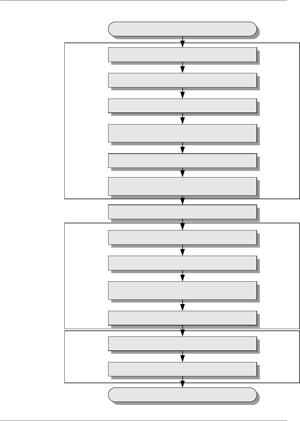
Figure 3-2 Commissioning procedure (transmission unavailable)
Local operation
before the
transmission is
available
Remote operation
after the
transmission is
available
Cooperation of
the local and
remote
operation after the
transmission is
available
Run
Run the BSC LMT
Check the transmission and networking
Check the consistency between
hardware installation and data configuration
Check the alarm information of the BTS
Commission the BTS services
Check the BTS environment alarms
End
Wait till the transmission is available
Run the Site Maintenance Terminal
Configure the basic data of the site
Check the active software version
Check the transmission
between the BBU and the RFU locally
Check the operation of the BTS
Check the hardware
connections of the BTS
3 Commissioning Procedure
BTS3900(A) GSM
Commissioning Guide
3-4 Huawei Proprietary and Confidential
Copyright © Huawei Technologies Co., Ltd.
Issue 02 (2009-04-20)

Table 3-2 Commissioning procedure (transmission unavailable)
No. Operation Procedure Mandat
ory/
Optiona
l
1Operation
on the
BTS side.
Run the Site Maintenance Terminal. For details, see
5.1 Starting the Site Maintenance Terminal.
Mandato
ry
2 Configure the basic data of the BTS such as boards of
the BTS and logical objects of the site to ensure that
the SMT can support the local commissioning tasks.
For details, see 5.2 Configuring the Basic Data of
the BTS.
Mandato
ry
3 Check the active software version. For details, see 5.3
Checking the Active Software Version on the
SMT.
Mandato
ry
4 Check the transmission between the BBU and RFU.
For details, see 5.4 Checking the Transmission
Between the BBU and RFU on the BTS Side.
Mandato
ry
5 Check the running status of the BTS. The procedure
for checking the running status of the BTS involves
checking the state of LEDs and alarm information. For
details, see 5.5 Checking the Running Status of the
BTS.
Mandato
ry
6 Check the hardware connection of the BTS. For
details, see 5.6 Checking the Hardware Connection
of the BTS.
Mandato
ry
7 Commission the antenna system. The commissioning
consists of the following items: output power of the
TRXs, VSWR, and connection between the antenna
system and the BTS. For details, see 6.1
Commissioning the Antenna System.
Optional
Wait till the transmission is available.
8 Operation
on the
BSC LMT
Run the BSC LMT software. For details, see 4.1
Starting the LMT.
Mandato
ry
9 Check the transmission and networking to ensure that
the transmission between the BBU and BSC, BBU and
RFU, cascaded BBUs, and cascaded RFUs is normal.
For details, see 4.2 Checking the Transmission and
Networking.
Mandato
ry
10 Check the software version and configuration data.
For details, see 4.3 Checking Software Version and
Data Configuration.
Mandato
ry
BTS3900(A) GSM
Commissioning Guide 3 Commissioning Procedure
Issue 02 (2009-04-20) Huawei Proprietary and Confidential
Copyright © Huawei Technologies Co., Ltd.
3-5

No. Operation Procedure Mandat
ory/
Optiona
l
11 Check the alarm information of the BTS. For details,
see 4.4 Checking the Alarm Information of the BTS
(on the LMT).
Mandato
ry
12 Perform the channel loopback test on the LMT to
ensure the normal operation of the signaling channel
and service channel. For details, see 6.2 Performing
the Loopback Test.
Optional
13 Operation
requiring
for the
cooperatio
n of the
BTS side
and BSC
side.
Commission the CS services and PS services. For
details, see 4.5 Commissioning the BTS Services.
Mandato
ry
14 Check the environment monitoring alarm. For details,
see 4.6.2 Checking the Environment Monitoring
Alarms on the LMT.
Mandato
ry
----End
3 Commissioning Procedure
BTS3900(A) GSM
Commissioning Guide
3-6 Huawei Proprietary and Confidential
Copyright © Huawei Technologies Co., Ltd.
Issue 02 (2009-04-20)

4 Commissioning the BTS (Transmission
Available)
About This Chapter
This describes how to commission the BTS when the transmission cable between the BSC and
the BTS is properly connected.
4.1 Starting the LMT
You can directly log in to the LMT, or log in to the LMT through the M2000 client.
4.2 Checking the Transmission and Networking
This describes how to check the transmission and networking. The purpose of checking the
transmission and networking is to ensure that the BTS3900A transmission cables and hardware
are correctly installed. The items to be checked consist of the transmission between the BBU
and the BSC, the transmission between the BBU and the RFU, the transmission between the
cascaded BTSs, and the transmission between the BTSs in ring topology.
4.3 Checking Software Version and Data Configuration
This describes how to check software version and data configuration to ensure the correctness
of the software version and configuration data. The items to be checked are the configuration
and status of the board, the software version information, and the consistency between the
hardware installation and the data configuration.
4.4 Checking the Alarm Information of the BTS (on the LMT)
This describes how to check the alarm information of the BTS on the BSC6000 Local
Maintenance Terminal. If an alarm is generated, you need clear the alarm based on the
suggestions in the BSS Help System.
4.5 Commissioning the BTS Services
This describes how to use an MS to test whether the BTS supports CS services and PS services.
4.6 Checking the BTS Environment Alarms
This describes how to check the BTS environment alarms. It also describes how to monitor the
operating environment of the BTS.
BTS3900(A) GSM
Commissioning Guide 4 Commissioning the BTS (Transmission Available)
Issue 02 (2009-04-20) Huawei Proprietary and Confidential
Copyright © Huawei Technologies Co., Ltd.
4-1
4.1 Starting the LMT
You can directly log in to the LMT, or log in to the LMT through the M2000 client.
Context
CAUTION
Do not modify the system time when the LMT application is running. Otherwise, critical errors
may occur on the system. If you have to modify the server time, stop the LMT application first.
The default user name and password for the first login are both admin. After you log in to the
system for the first time, you are required to change the password. The new password should
comply with the default password policy.
Procedure
lDirectly log in to the LMT.
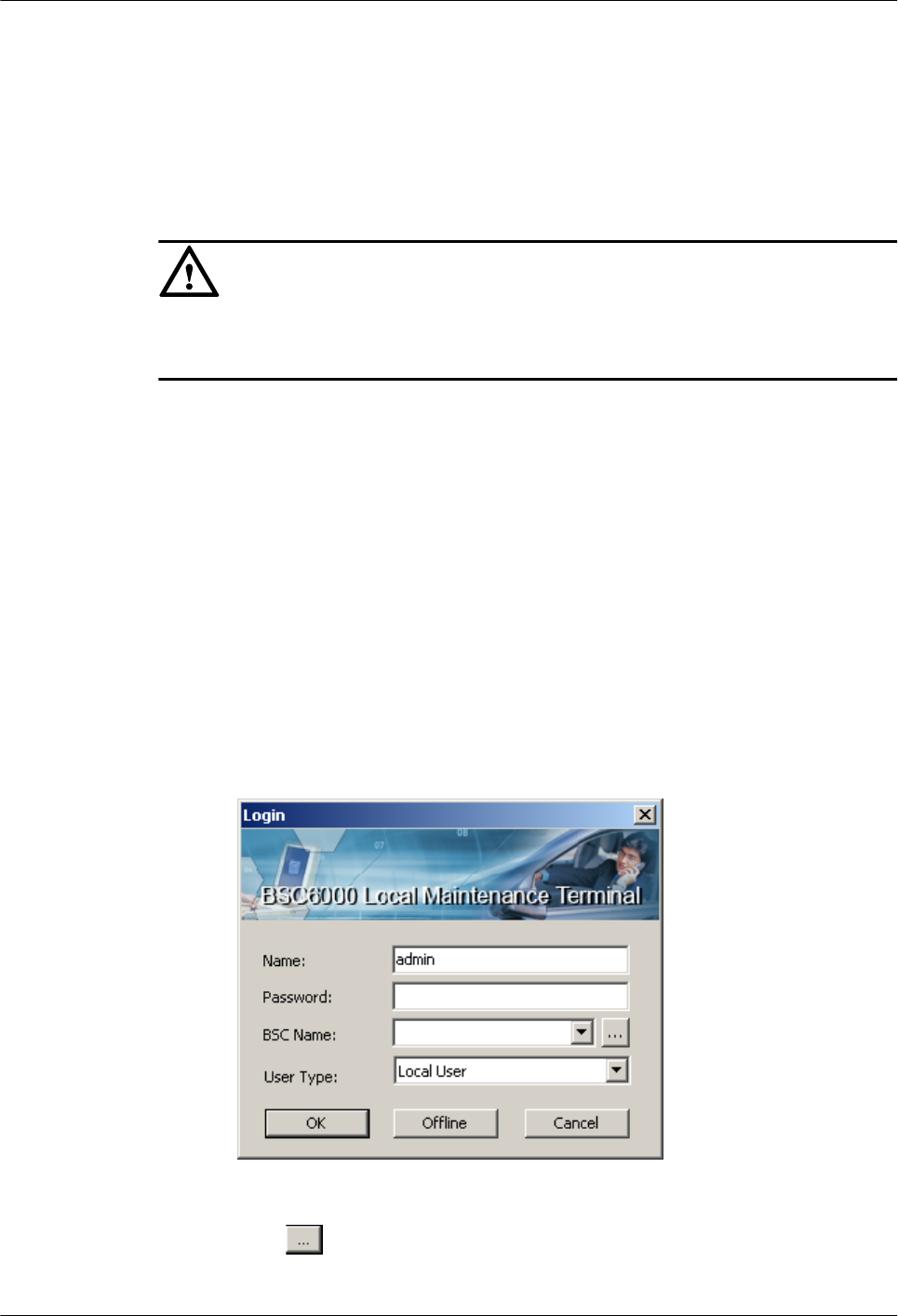
1. Choose Start > All Programs > Huawei Local Maintenance Terminal >
BSC6000V900B008Cxx > BSC6000 Local Maintenance Terminal. The BSC6000
Local Maintenance Terminal window is displayed, as shown in Figure 4-1.
–If you can find the target BSC for login from the BSC Name drop-down list, go
to Step 5.
–If you cannot find the target BSC for login from the BSC Name drop-down list,
go to Step 2.
Figure 4-1 Login dialog box of the BSC6000 Local Maintenance Terminal
2. Click . The BSC Management dialog box is displayed, as shown in Figure
4-2.
4 Commissioning the BTS (Transmission Available)
BTS3900(A) GSM
Commissioning Guide
4-2 Huawei Proprietary and Confidential
Copyright © Huawei Technologies Co., Ltd.
Issue 02 (2009-04-20)
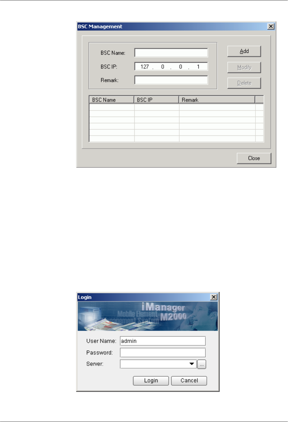
Figure 4-2 BSC Management dialog box
3. Type the IP address of the BSC, the name of the BSC, and the remarks (optional) in
corresponding fields. Then, click Add.
4. Click Close to return to the Login dialog box, as shown in Figure 4-1.
5. Type the user name and the password in the Name and Password text boxes. Select
the BSC name from the BSC Name drop-down list, and set User Type to Local
User. Then, click OK.
lLog in to the BSC LMT through the M2000 client.
1. Choose Start > All Programs > iManager M2000 Client > M2000 Client.
The Login dialog box is displayed, as shown in Figure 4-3.
Figure 4-3 Login dialog box of the M2000 client
BTS3900(A) GSM
Commissioning Guide 4 Commissioning the BTS (Transmission Available)
Issue 02 (2009-04-20) Huawei Proprietary and Confidential
Copyright © Huawei Technologies Co., Ltd.
4-3
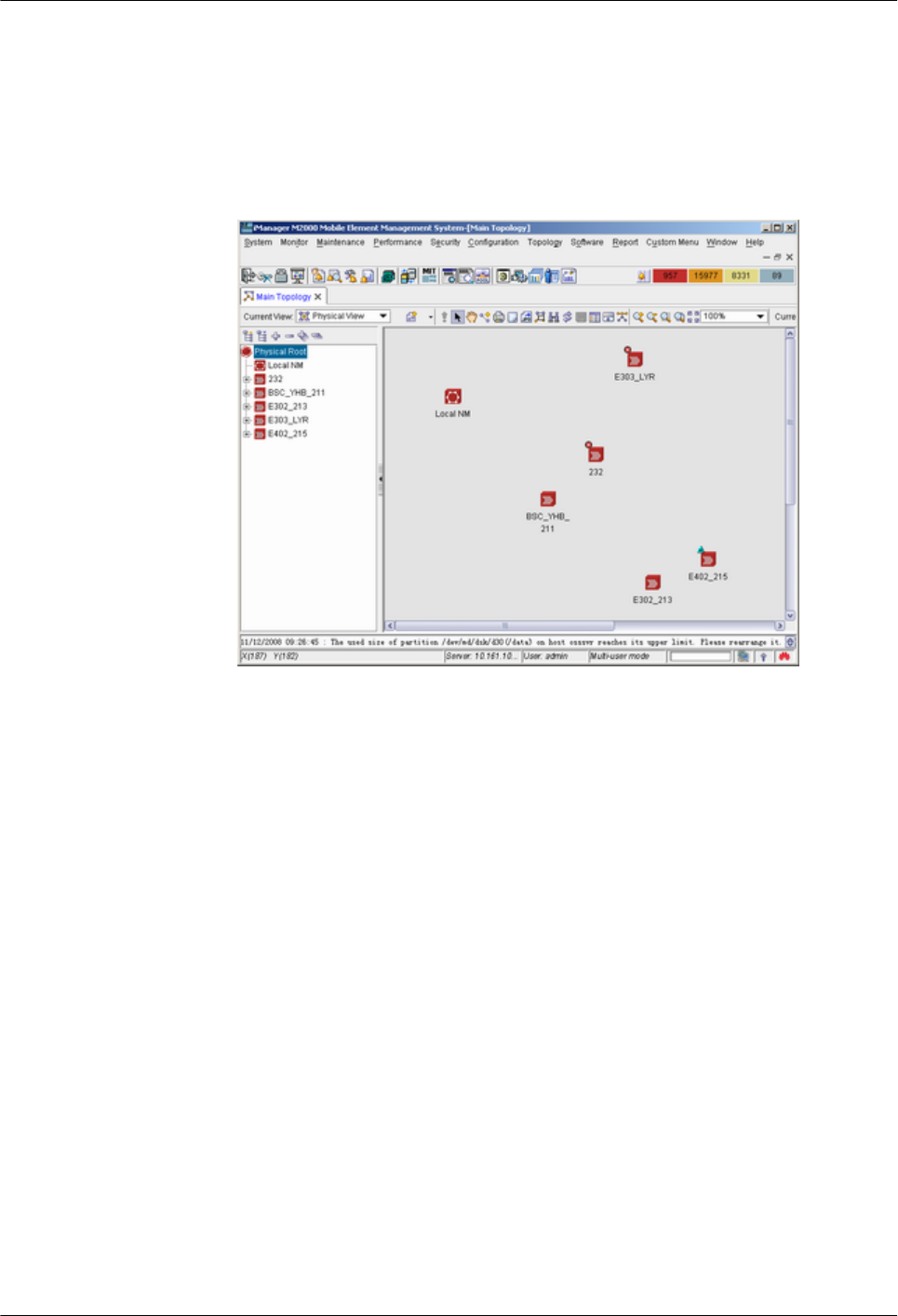
2. Enter user name in User Name, enter the password in Password, and enter IP address
of the server in Server. Click Login.
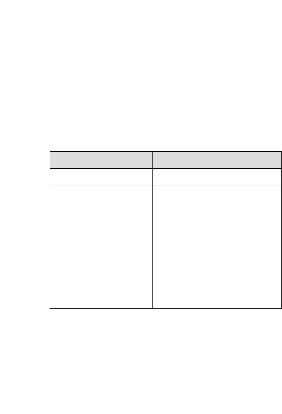
3. In the iManager M2000 Mobile Element Management System window, choose
Topology > Main Topology, as shown in Figure 4-4. Main Topology is displayed
on the left side of the dialog box.
Figure 4-4 iManager M2000 Mobile Element Management System window
4. Choose Physical Root on the Main Topology tab page, right-click the BSC that the
BTS belongs to, and choose Maintenance Client from the displayed shortcut menu.
The BSC6000 Local Maintenance Terminal window is displayed.
----End
4.2 Checking the Transmission and Networking
This describes how to check the transmission and networking. The purpose of checking the
transmission and networking is to ensure that the BTS3900A transmission cables and hardware
are correctly installed. The items to be checked consist of the transmission between the BBU
and the BSC, the transmission between the BBU and the RFU, the transmission between the
cascaded BTSs, and the transmission between the BTSs in ring topology.
4.2.1 Checking the Transmission Between the RRU and the BBU or Between the BBU and the
BSC on the LMT
This describes how to check the transmission between the BBU and the BSC and the transmission
between the BBU and the RFU.
4.2.2 Checking the Transmission Between Cascaded BTSs
This describes how to check the transmission between cascaded BTSs when there are cascaded
BTSs on site. The following description takes the level 3 cascaded BTSs as an example, and
describes how to check the transmission between cascaded BTSs.
4 Commissioning the BTS (Transmission Available)
BTS3900(A) GSM
Commissioning Guide
4-4 Huawei Proprietary and Confidential
Copyright © Huawei Technologies Co., Ltd.
Issue 02 (2009-04-20)
4.2.3 Checking the Transmission Between BTSs in Ring Topology
This describes how to check the transmission between BTSs in ring topology. The following
description is based on three BTSs in ring topology.
4.2.1 Checking the Transmission Between the RRU and the BBU or
Between the BBU and the BSC on the LMT
This describes how to check the transmission between the BBU and the BSC and the transmission
between the BBU and the RFU.
Procedure
Step 1 Choose BSC Maintenance > Maintain Transmission and Signaling > Maintain LAPD
Link on the LMT.
The Maintain LAPD Link dialog box is displayed.
Step 2 Select the link and site to be queried, and click Query. The result is displayed on the Query
Result window.
If... Then...
OML links and RSL links are normal End the checking task.
OML links or RSL links are faulty Check for the related alarm, for example, 1000
LAPD_OML Fault alarm. Then rectify the fault
according to the alarm help.
The possible causes of the faulty links are as
follows:
lThe BTS does not work properly.
lThe transmission cables between the BSC and the
RFU or BBU are damaged, or the ports to which
the transmission cables are connected are faulty.
NOTE
If the BTS data has just been configured on the LMT, you
should reset the BBU first. After the BBU detects the
information sent by the BSC and initiates the link setup
procedure, the OML link can be detected.
----End
Example
lCheck whether the OML link between the BBU and the BSC is normal. If the state of the
OML link is normal, the BBU is properly connected to the BSC, as shown in Figure 4-5.
BTS3900(A) GSM
Commissioning Guide 4 Commissioning the BTS (Transmission Available)
Issue 02 (2009-04-20) Huawei Proprietary and Confidential
Copyright © Huawei Technologies Co., Ltd.
4-5
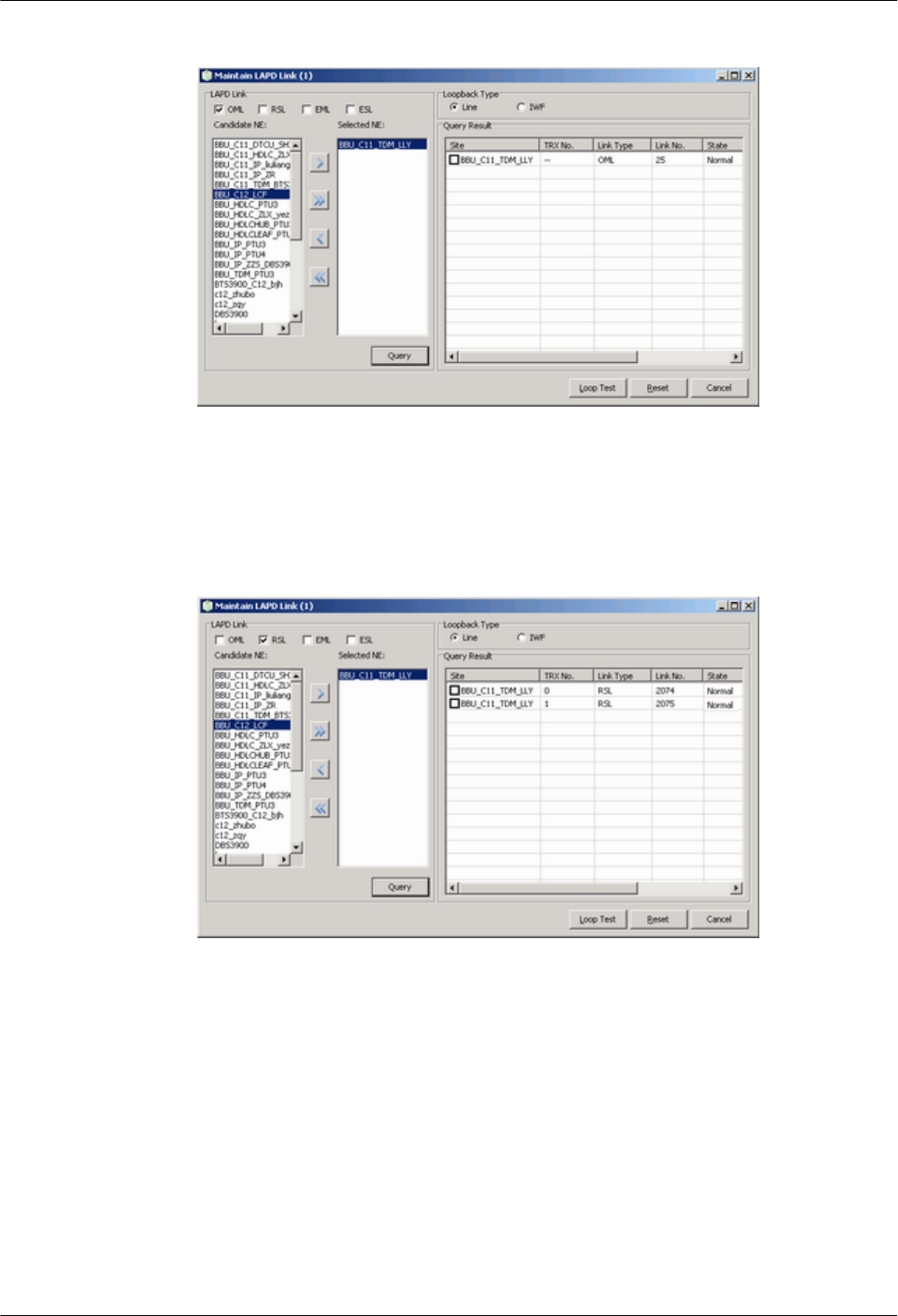
Figure 4-5 Check whether the link between the BBU and the BSC is normal
lCheck whether the RSL link between the BBU and the RFU is normal. If the state of the
RSL link is normal, the BBU is properly connected to the RFU, as shown in Figure 4-6.
Figure 4-6 Check whether the link between the BBU and the RFU is normal
4.2.2 Checking the Transmission Between Cascaded BTSs
This describes how to check the transmission between cascaded BTSs when there are cascaded
BTSs on site. The following description takes the level 3 cascaded BTSs as an example, and
describes how to check the transmission between cascaded BTSs.
Prerequisite
lThe physical connection between cascaded BTSs on the BTS side is complete.
lThe BTS is in TDM or HDLC transmission mode.
4 Commissioning the BTS (Transmission Available)
BTS3900(A) GSM
Commissioning Guide
4-6 Huawei Proprietary and Confidential
Copyright © Huawei Technologies Co., Ltd.
Issue 02 (2009-04-20)
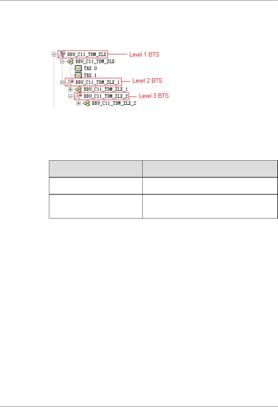
Context
Figure 4-7 shows the cascaded BTSs in the BSC6000 Local Maintenance Terminal window.
Figure 4-7 Cascaded BTSs on the LMT
Procedure
Step 1 Check whether cascaded BTSs are configured on the LMT.
If... Then...
Cascaded BTSs are configured Go to Step 2.
Cascaded BTSs are not configured See the BSC Initial Configuration Guide to configure
the BTSs.
Step 2 In the left pane of the BSC6000 Local Maintenance Terminal window, select the level 2 BTS
and level 3 BTS respectively. Check whether each board on the Site Device Panel tab ipage s
displayed in green, as shown in Figure 4-8.
lIf the board is displayed in green, you can infer that the board is functional. End this task.
lIf the board is not displayed in green, you can infer that the transmission between cascaded
BTSs is abnormal. Go to Step 3.
BTS3900(A) GSM
Commissioning Guide 4 Commissioning the BTS (Transmission Available)
Issue 02 (2009-04-20) Huawei Proprietary and Confidential
Copyright © Huawei Technologies Co., Ltd.
4-7

Figure 4-8 Site Device Panel tab page
Step 3 On the BTS side, check the physical connection between the BBU of the level 1 BTS and BBU
of the level 2 BTS. Normally, the T1 of the first E1/T1 of the level 2 BTS should be connected
to the R2 of the second E1/T1 of the level 1 BTS, and the R1 of the first E1/T1 of the level 2
BTS should be connected to the T2 of the second E1/T1 of the level 1 BTS.
lIf the link is normal, the status of the LIU1 LED on the level 1 BTS and the LIU0 LED on
the level 2 BTS changes from ON disconnected to OFF connected.
lIf the link is still not normal, contact Huawei technical support engineers on the BTS side
for troubleshooting.
Step 4 On the BTS side, see Step 3 to check the physical connection between the BBU of the level 2
BTS and BBU of the level 3 BTS.
----End
4.2.3 Checking the Transmission Between BTSs in Ring Topology
This describes how to check the transmission between BTSs in ring topology. The following
description is based on three BTSs in ring topology.
Prerequisite
The physical connection between BTSs in ring topology on the BTS side is complete.
Context
lFigure 4-9 shows the connection between BTSs in ring topology. A, B, C, and D show the
positions where the link may be broken during the ring topology transmission.
4 Commissioning the BTS (Transmission Available)
BTS3900(A) GSM
Commissioning Guide
4-8 Huawei Proprietary and Confidential
Copyright © Huawei Technologies Co., Ltd.
Issue 02 (2009-04-20)
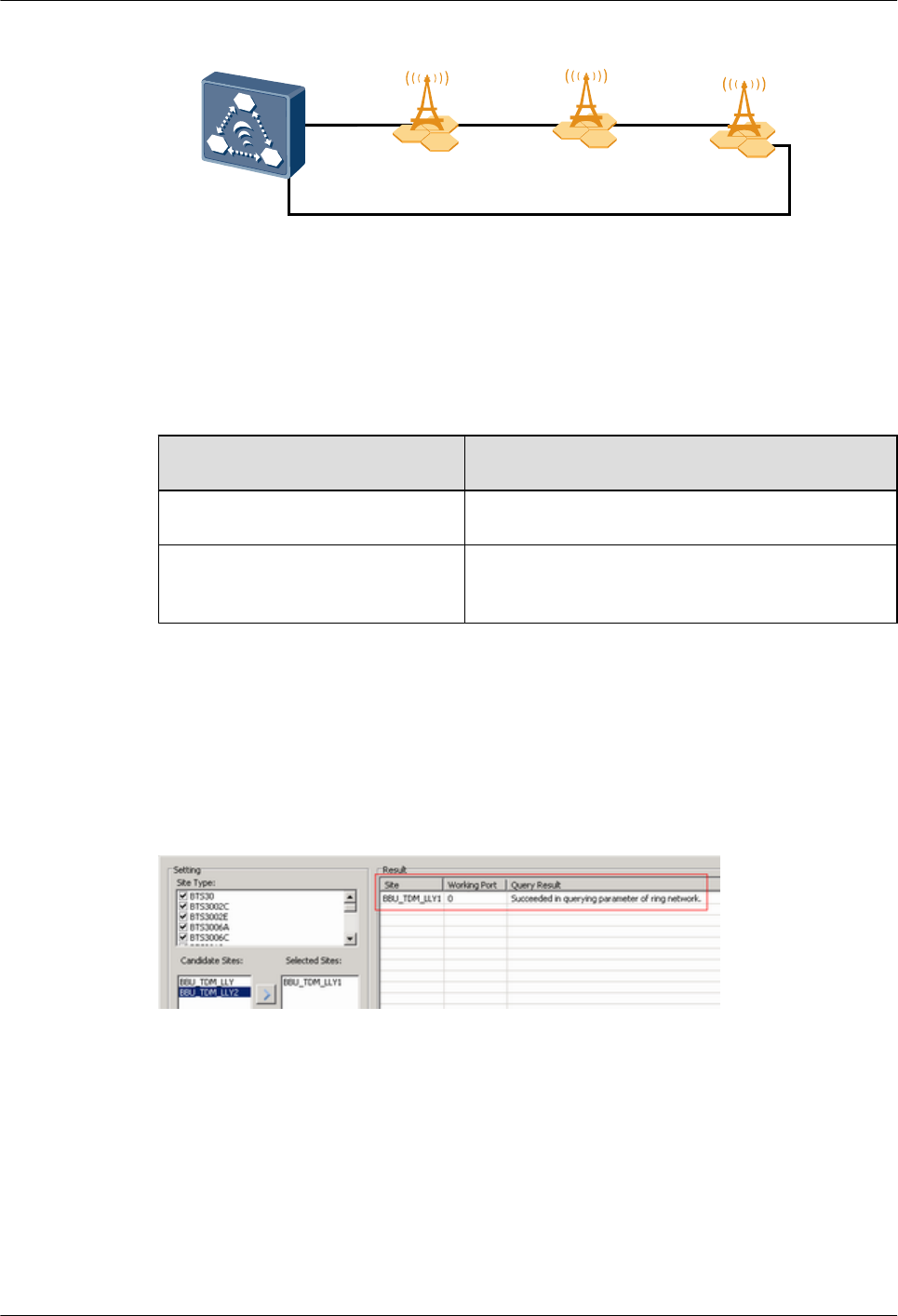
Figure 4-9 Connection between ring topology BTSs
BSC
BTS0 BTS1 BTS2
A B C
D
lIn this document, set the forward port to port 0 and reverse port to port 1.
Procedure
Step 1 Check whether of BTSs in ring topology are configured on the LMT.
If... Then...
The ring topology is configured Go to Step 2.
The ring topology is not configured Configure the ring topology. For details, see the BSC
Initial Configuration Guide.
Step 2 In the BSC6000 Local Maintenance Terminal window, choose BTS Maintenance > Maintain
Site > Maintain Ring Network, and the Maintain Ring Network dialog box is displayed.
Step 3 In the Setting text box, select Site Type and level 2 BTS, and click Query. The query results
are displayed in the Result area, as shown in Figure 4-10. Port 0 serves as the working port.
Query Result shows Ring Topology Parameter Query Success. The query result indicates
that the link setup is successful and the OML receives the related data configuration.
Figure 4-10 Maintain Ring Network dialog box
Step 4 Check the switchover of the forward ring port and the reverse ring port on the LMT.
1. In the Query Result area, right-click the level 2 BTS. A dialog box is displayed. Click
Switch. The Confirm dialog box is displayed, as shown in Figure 4-11.
BTS3900(A) GSM
Commissioning Guide 4 Commissioning the BTS (Transmission Available)
Issue 02 (2009-04-20) Huawei Proprietary and Confidential
Copyright © Huawei Technologies Co., Ltd.
4-9
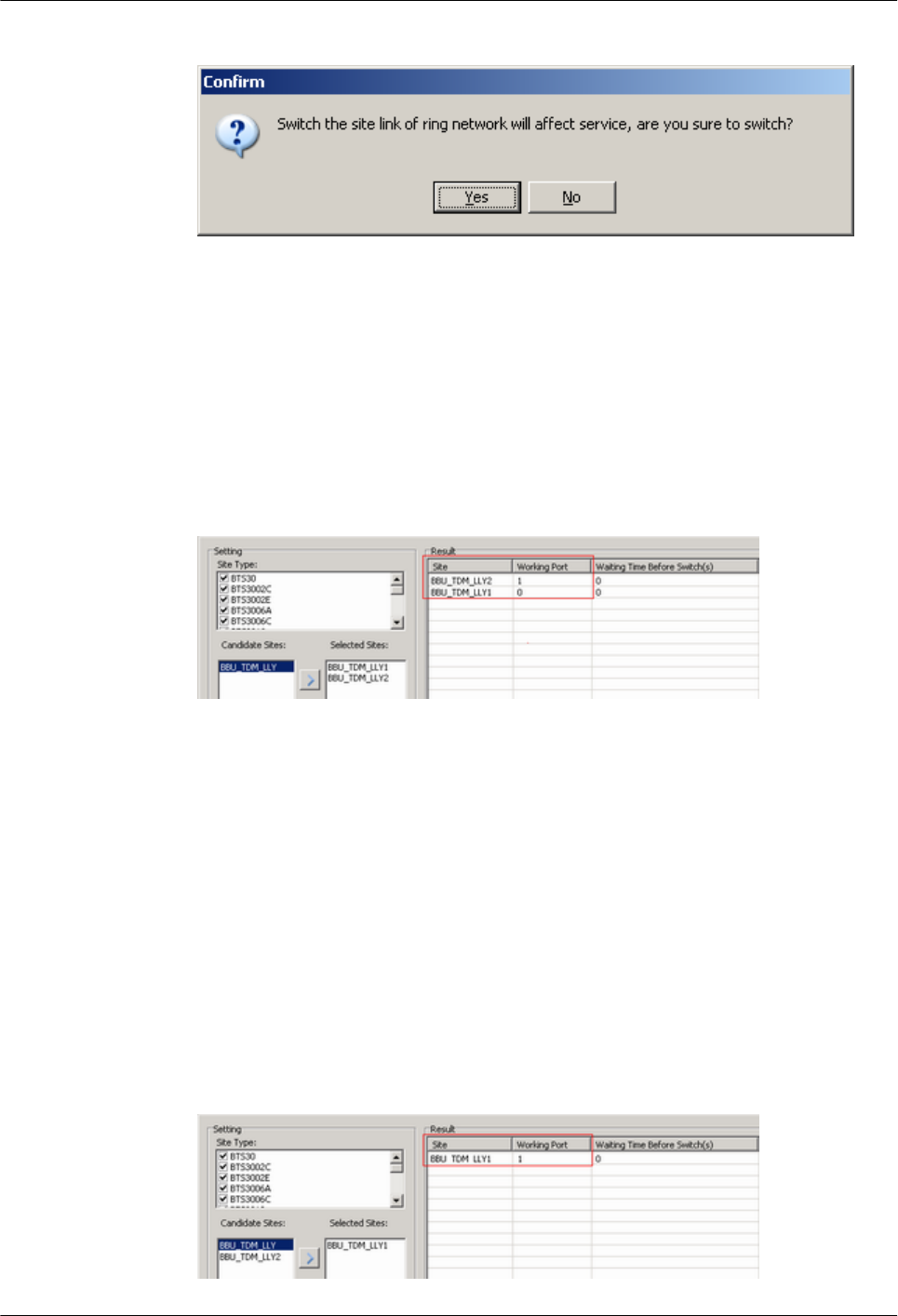
Figure 4-11 Confirm dialog box
2. ClickYes, the Switchover Success dialog box is displayed. The level 2 BTS and level 3
BTS reset automatically.
3. After the level 2 and level 3 BTS are reset, query the information about the ring topology
of the level 2 and level 3 BTSs. Figure 4-12 shows the query result. The level 3 BTS is
successfully connected in the reverse direction, and the working port is changed from port
0 to port 1. You can infer that the BTS can perform the switchover from the forward ring
port to the reverse ring port.
Figure 4-12 Result of the ring topology switchover (1)
4.
Step 5 Disconnect the BTSs in ring topology manually, and check the automatic switchover of BTSs
in ring topology. When the physical connection between BTSs in ring topology is disconnected,
the lower-level BTS at the disconnected point works in the reverse link, and the upper-level BTS
works in the forward link.
1. On the BTS side, disconnect the transmission cable between the level 1 BTS and level 2
BTS. The level 2 BTS resets automatically.
2. After the reset of the level 2 BTS is complete, see Step 2 and Step 3 to query the information
about ring topology. Figure 4-13 shows the query result. The working port of the level 2
BTS is changed from port 0 to port 1. You can infer that the automatic switchover of the
lower-level BTS is complete.
Figure 4-13 Result of the ring topology switchover (2)
4 Commissioning the BTS (Transmission Available)
BTS3900(A) GSM
Commissioning Guide
4-10 Huawei Proprietary and Confidential
Copyright © Huawei Technologies Co., Ltd.
Issue 02 (2009-04-20)

CAUTION
In normal situations, after Step 4 or Step 5 is performed, the cascaded BTSs will automatically
switch over to the forward link. If the BTSs fail to switch over to the forward link automatically,
check the connections of the transmission cables, for example, the connections of the TX and
RX ends of the E1 cable.
----End
4.3 Checking Software Version and Data Configuration
This describes how to check software version and data configuration to ensure the correctness
of the software version and configuration data. The items to be checked are the configuration
and status of the board, the software version information, and the consistency between the
hardware installation and the data configuration.
4.3.1 Checking the Board Configuration and Status on the LMT
This describes how to check the configuration and status of the BTS boards.
4.3.2 Checking the Current Software Version on the LMT
This describes how to check the current software version of the boards and modules of the BTS.
4.3.3 Checking the Consistency Between Hardware Installation and Data Configuration
This describes how to check the consistency between hardware installation and data
configuration. The consistency is confirmed by checking the configuration and board status on
the LMT.
4.3.1 Checking the Board Configuration and Status on the LMT
This describes how to check the configuration and status of the BTS boards.
Procedure
Step 1 Click Site Device Panel to check the configured boards, as shown in Figure 4-14.
BTS3900(A) GSM
Commissioning Guide 4 Commissioning the BTS (Transmission Available)
Issue 02 (2009-04-20) Huawei Proprietary and Confidential
Copyright © Huawei Technologies Co., Ltd.
4-11
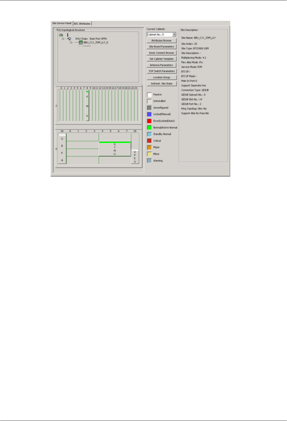
Figure 4-14 Site Device Panel tab page
Step 2 Check the status of boards: The green color indicates that the board is Normal. The red color
indicates that the board is Faulty. The white color indicates that the board is Passive, that is,
the board has no input power.
Step 3 Check the board status further: Right-click the board to be queried, and then choose Query
Board Information from the shortcut menu.
The Query Board Information dialog box is displayed, as shown in Figure 4-15.
4 Commissioning the BTS (Transmission Available)
BTS3900(A) GSM
Commissioning Guide
4-12 Huawei Proprietary and Confidential
Copyright © Huawei Technologies Co., Ltd.
Issue 02 (2009-04-20)
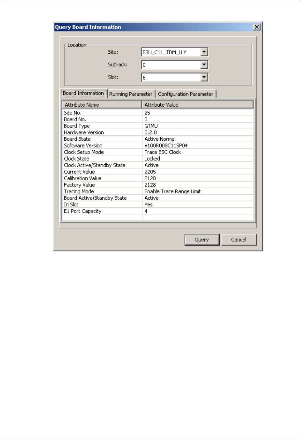
Figure 4-15 Query Board Information dialog box
Step 4 Check whether Board State is Actively Normal in the Query Board Information dialog box.
If the status is Faulty, go to Step 5 to check the alarm information.
Step 5 See 4.4 Checking the Alarm Information of the BTS (on the LMT) to check the alarm
information and clear the alarm according to the BSS Alarm Reference.
----End
4.3.2 Checking the Current Software Version on the LMT
This describes how to check the current software version of the boards and modules of the BTS.
Procedure
Step 1 In the BSC6000 Local Maintenance Terminal window, choose BTS Maintenance > Query
Board Running Software Version.
The Query Board Running Software Version dialog box is displayed.
Step 2 Select BTS3900/BTS3900A under Site Type, and select the site to be queried under Candidate
Sites, and then add the site to the Selected Sites area. Click Start to query the software version
of the BTS3900/BTS3900A boards, as shown in Figure 4-16.
BTS3900(A) GSM
Commissioning Guide 4 Commissioning the BTS (Transmission Available)
Issue 02 (2009-04-20) Huawei Proprietary and Confidential
Copyright © Huawei Technologies Co., Ltd.
4-13
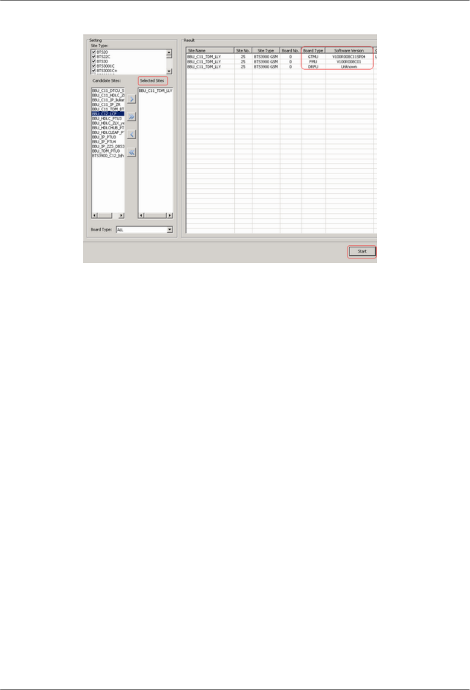
Figure 4-16 Query Board Running Software Version dialog box
Step 3 If the software version is correct, end this task. If the software version is incorrect, update the
software version through the loading and activation function of the LMT. For details, see the
BSC LMT User Guide.
----End
4.3.3 Checking the Consistency Between Hardware Installation and
Data Configuration
This describes how to check the consistency between hardware installation and data
configuration. The consistency is confirmed by checking the configuration and board status on
the LMT.
Context
lCPRI connections: The port numbers SFP0 to SFP5 in the RXU topological structure area
on the LMT correspond to the ports CPRI0 to CPRI5 on the panel of the BBU.
lSlots for the RFUs: On the LMT, the RFUs are configured in subrack 3. The slot numbers
of the RFUs are based on the configuration sequence of the TRXs, starting from slot 0. In
actual installation, the installation slot of the RFU is determined by the actual requirements.
lThe relations between the data configuration and the physical connections of monitoring
boards connected to RS485 ports are described as follows:
–Figure 4-17 shows the relation between data configuration and physical connection of
the BTS3900 monitoring boards.
4 Commissioning the BTS (Transmission Available)
BTS3900(A) GSM
Commissioning Guide
4-14 Huawei Proprietary and Confidential
Copyright © Huawei Technologies Co., Ltd.
Issue 02 (2009-04-20)
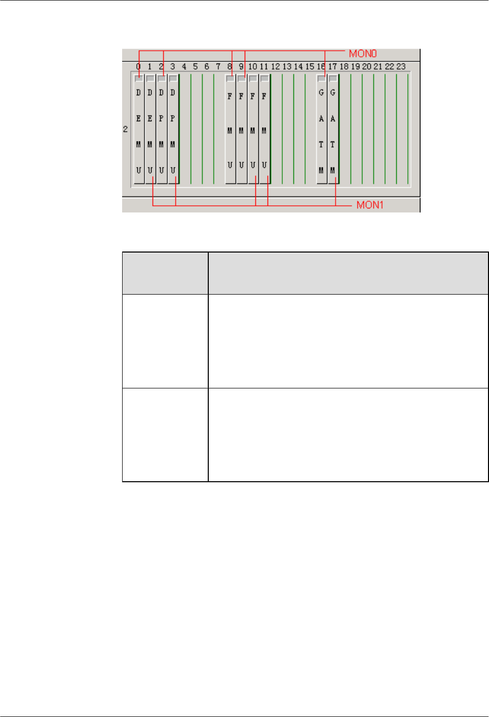
Figure 4-17 Relation between data configuration and physical connection of the
BTS3900 monitoring boards
Monitoring Port
on the GTMU
Relation Between Data Configuration and Physical
Connection
MON0 In subrack 2, the DEMU in slot 0, DPMU in slot 2, FMUs in slot
8 and 9, and GATM in slot 16 are all connected to the MON0 port
on the GTMU physically. Physical connections: The monitoring
signal cable connects the MON0 port on the GTMU and one
monitoring board, and the other monitoring boards are connected
to this board in cascaded mode.
MON1 In subrack 2, the DEMU in slot 1, DPMU in slot 3, FMUs in slot
10 and 11, GATM in slot 17 are all connected to the MON1 port
on the GTMU physically. Physical connections: The monitoring
signal cable connects the MON1 port on the GTMU and one
monitoring board, and the other monitoring boards are connected
to this board in cascaded mode.
–Figure 4-18 shows the relation between data configuration and physical connection of
the BTS3900A monitoring boards.
BTS3900(A) GSM
Commissioning Guide 4 Commissioning the BTS (Transmission Available)
Issue 02 (2009-04-20) Huawei Proprietary and Confidential
Copyright © Huawei Technologies Co., Ltd.
4-15
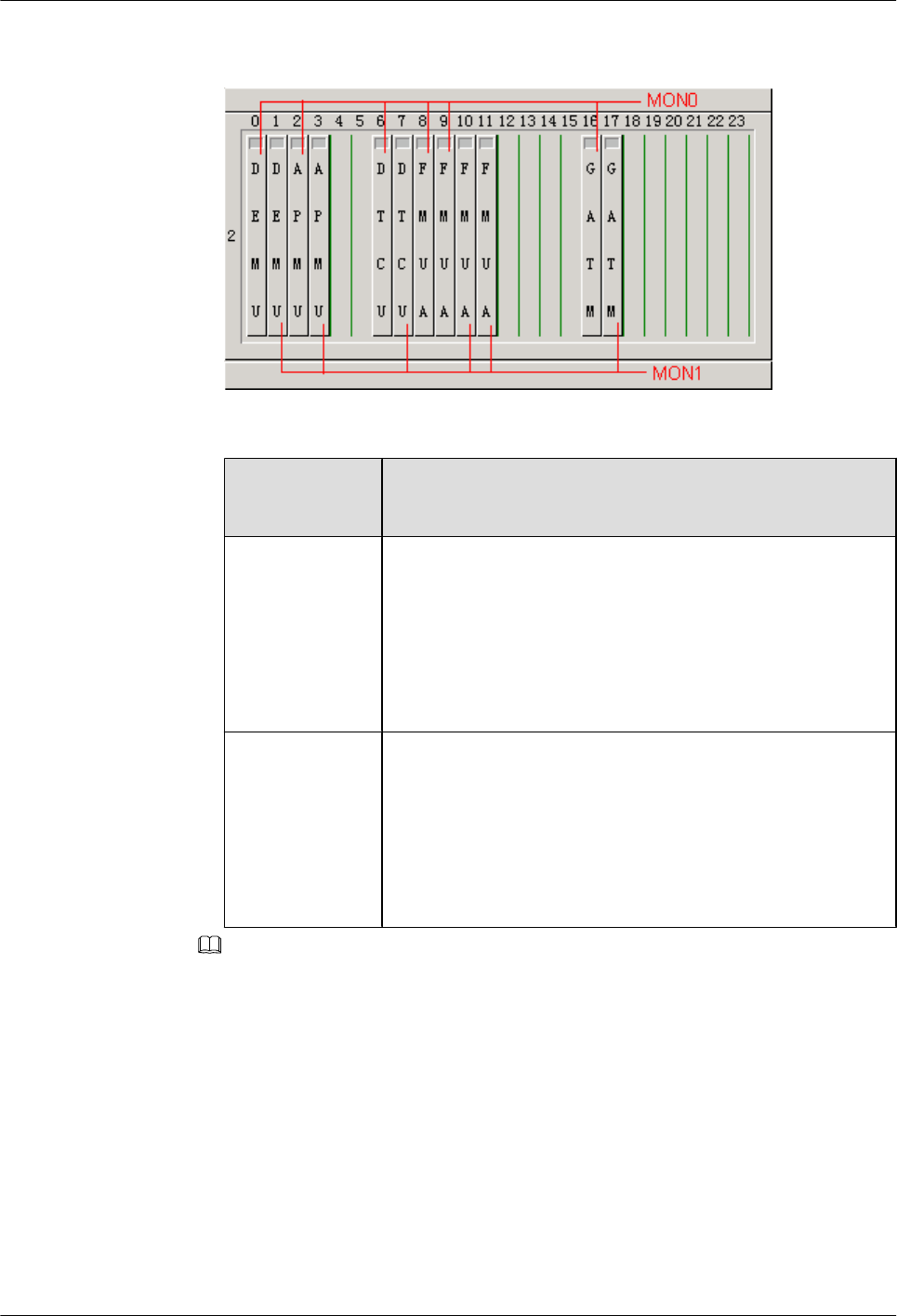
Figure 4-18 Relation between data configuration and physical connection of the
BTS3900A monitoring boards
Monitoring Port
on the GTMU
Relation Between Data Configuration and Physical
Connection
MON0 In subrack 2, the DEMU in slot 0, DPMU or APMU in slot 2,
DTCU in slot 6, FMUs or FMUAs in slot 8 and 9, and GATM in
slot 16 are all connected to the MON0 port on the GTMU
physically. Physical connections: The monitoring signal cable
connects the MON0 port on the GTMU and one monitoring
board, and the other monitoring boards are connected to this board
in cascaded mode.
MON1 In subrack 2, the DEMU in slot 1, DPMU or APMU in slot 3,
DTCU in slot 7, FMUs or FMUAs in slot 10 and 11, and GATM
in slot 17 are all connected to the MON1 port on the GTMU
physically. Physical connections: The monitoring signal cable
connects the MON1 port on the GTMU and one monitoring
board, and the other monitoring boards are connected to this board
in cascaded mode.
NOTE
lConnection between the MON0 port and the two FMUs or FMUAs: The FMU or FMUA in slot
9 is connected to the MON0 port through the FMU or FMUA in slot 8.
lConnection between the MON1 port and the two FMUs or FMUAs: The FMU or FMUA in slot
11 is connected to the MON1 port through the FMU or FMUA in slot 10.
lA maximum of two DEMUs, DPMUs, APMUs, DTCUs, and GATMs can be configured for each
BTS, while a maximum of four FMUs or FMUAs can be configured.
Procedure
Step 1 In the BSC6000 Local Maintenance Terminal window, click the Site Device Panel tab page
to check the board configuration of the BTS.
Step 2 Check the boards status. If the configured boards are operational, the boards are shown in green,
as shown in Figure 4-19. If the boards are shown in red, the boards are faulty.
4 Commissioning the BTS (Transmission Available)
BTS3900(A) GSM
Commissioning Guide
4-16 Huawei Proprietary and Confidential
Copyright © Huawei Technologies Co., Ltd.
Issue 02 (2009-04-20)
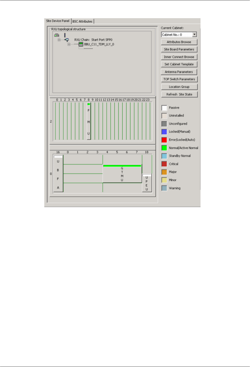
Figure 4-19 Site Device Panel tab page
Step 3 Check board status further: Right-click the board to be queried, and then choose the Query
Board Information dialog box from the shortcut menu. The Query Board Information dialog
box is displayed.
Step 4 Check whether the Board State is Active Normal in the Board Information tab page, as shown
in Figure 4-20.
lIf it is Active Normal, the hardware installation and data configuration of the boards are
consistent.
lIf it is Faulty, check for the related alarms. For details about how to handle the alarms, see
the BSS Alarm Reference.
BTS3900(A) GSM
Commissioning Guide 4 Commissioning the BTS (Transmission Available)
Issue 02 (2009-04-20) Huawei Proprietary and Confidential
Copyright © Huawei Technologies Co., Ltd.
4-17
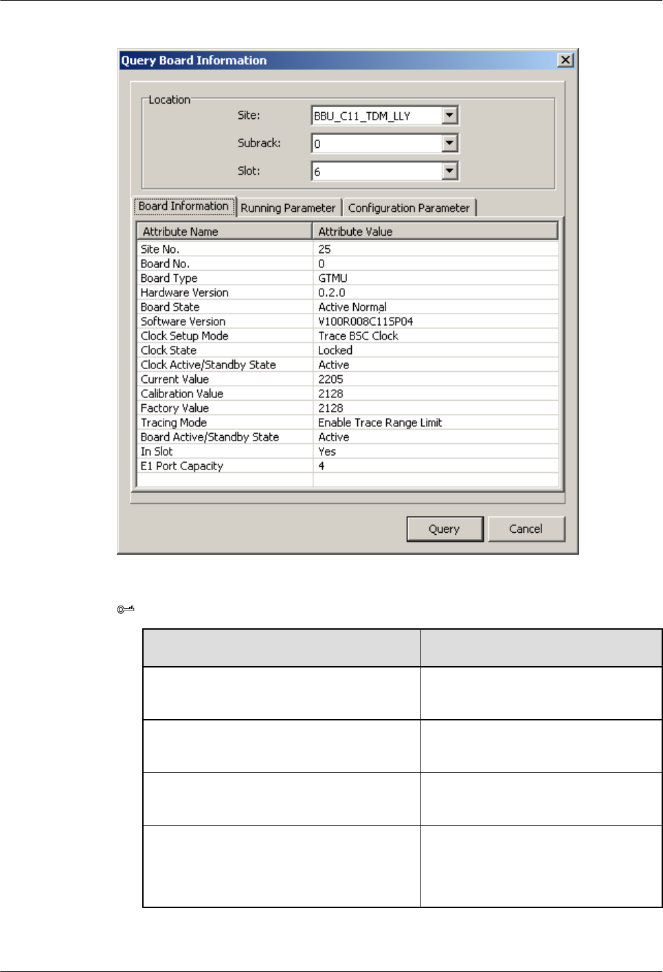
Figure 4-20 Query Board Information dialog box
TIP
If... Then...
The number of BBUs installed is different from the
number of BBUs configured
The system reports E1 Local Alarm.
More RFUs are installed than those configured The system reports SFP Port Inconsistency
Alarm.
Fewer RFUs are installed than those configured The system reports SFP Port Inconsistency
Alarm and TRX Communication Alarm.
A board other than the BBU and RFU is configured but
not installed.
The system reports **** Communication
Alarm, such as Fan Subassembly
Communication Alarm and PMU
Communication Alarm.
4 Commissioning the BTS (Transmission Available)
BTS3900(A) GSM
Commissioning Guide
4-18 Huawei Proprietary and Confidential
Copyright © Huawei Technologies Co., Ltd.
Issue 02 (2009-04-20)

If... Then...
A board other than the BBU and RFU is installed but
not configured
No alarm is reported.
----End
4.4 Checking the Alarm Information of the BTS (on the
LMT)
This describes how to check the alarm information of the BTS on the BSC6000 Local
Maintenance Terminal. If an alarm is generated, you need clear the alarm based on the
suggestions in the BSS Help System.
Procedure
Step 1 Choose BTS in the navigation bar on the left pane of the BSC6000 Local Maintenance
Terminal. In the displayed Site Device Panel tab page, check whether alarms related to the
BTS boards exist. Check the status of boards: The green color indicates that the board is
Normal. The red color indicates that the board is Error, and an alarm exists. Figure 4-21 shows
the Site Device Panel tab page.
BTS3900(A) GSM
Commissioning Guide 4 Commissioning the BTS (Transmission Available)
Issue 02 (2009-04-20) Huawei Proprietary and Confidential
Copyright © Huawei Technologies Co., Ltd.
4-19
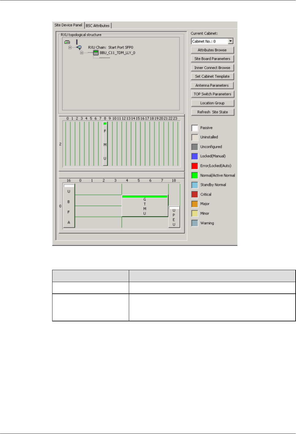
Figure 4-21 Site Device Panel tab page
If... Then...
No alarm is generated Repeat 1 to check the alarm information of other BTSs.
An alarm is generated Go to 2. Check the alarm generated on this BTS through Alarm
Maintenance. Clear the alarm based on the troubleshooting
suggestions.
Step 2 Alarm maintenance: Check the alarms of the BTS.
1. Choose Alarm Maintenance > Browse Alarm. The Browse Alarm dialog box is
displayed.
2. Right-click an alarm, and choose Filter Alarms... from the shortcut menu. The Filter
Alarm Condition dialog box is displayed, as shown in Figure 4-22.
4 Commissioning the BTS (Transmission Available)
BTS3900(A) GSM
Commissioning Guide
4-20 Huawei Proprietary and Confidential
Copyright © Huawei Technologies Co., Ltd.
Issue 02 (2009-04-20)
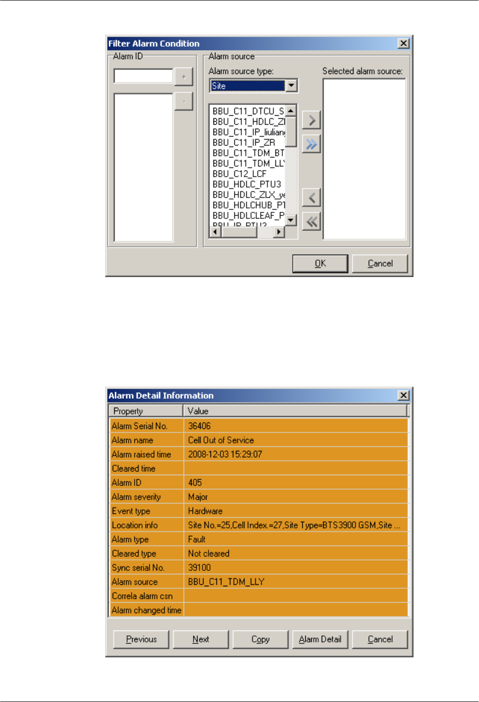
Figure 4-22 Filter Alarm Condition dialog box
3. Choose the Site to be queried, and click OK.
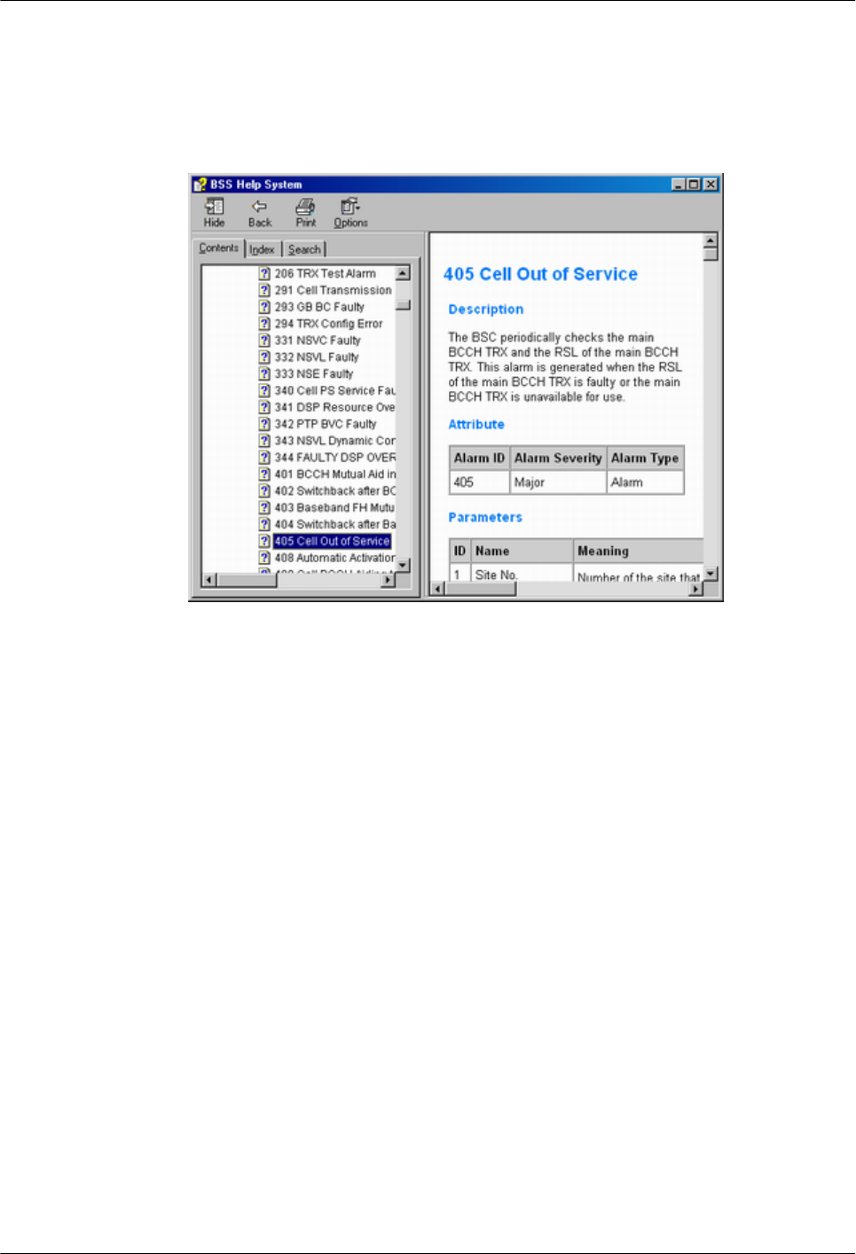
4. Double-click an alarm. The Alarm Detail Information dialog box is displayed, as shown
in Figure 4-23.
Figure 4-23 Alarm Detail Information dialog box
BTS3900(A) GSM
Commissioning Guide 4 Commissioning the BTS (Transmission Available)
Issue 02 (2009-04-20) Huawei Proprietary and Confidential
Copyright © Huawei Technologies Co., Ltd.
4-21
5. Click Alarm Detail, and the BSS Help System is displayed, as shown in Figure 4-24. Handle
the alarm according to the BSS Alarm Reference.
Figure 4-24 BSS Help System
----End
4.5 Commissioning the BTS Services
This describes how to use an MS to test whether the BTS supports CS services and PS services.
Prerequisite
lThe transmission between the BSC and the BTS is normal, and the transmission between
the BSC and the LMT is normal.
lThe current software version and data configuration are correct.
lNo alarm related to disruption of BTS services is reported on the LMT.
4.5.1 Testing the CS Services
This describes how to test the CS services by making test calls between two MSs or between an
MS and a PSTN phone.
4.5.2 Commissioning PS Services
This describes how to commission PS services by website browsing and file downloading
through an MS. A laptop is required to monitor the commissioning. You need to commission
only the BTS that is configured with the GPRS or EGPRS services.
4 Commissioning the BTS (Transmission Available)
BTS3900(A) GSM
Commissioning Guide
4-22 Huawei Proprietary and Confidential
Copyright © Huawei Technologies Co., Ltd.
Issue 02 (2009-04-20)
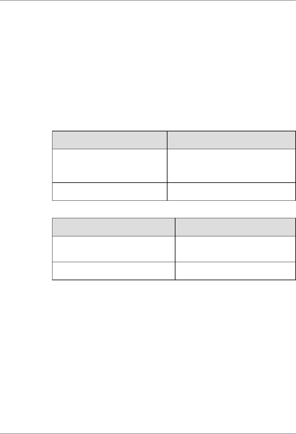
4.5.1 Testing the CS Services
This describes how to test the CS services by making test calls between two MSs or between an
MS and a PSTN phone.
Prerequisite
lTwo test MSs which support GSM are registered with the HLR.
lThe logical cells to be checked are activated.
lThe BSC functions properly.
Procedure
Step 1 Power on one test MS, and check that the MS automatically searches for the GSM network.
If... Then...
The testing MS fails to find the GSM
network
Check that the test MS is configured with the SIM
card and the SIM card supports authentication
and encryption.
The test MS finds the GSM network Go to Step 2.
Step 2 Lock the testing MS on a frequency in a logical cell under the BTS.
If... Then...
The test lasts at least 40n minutes (n is the
number of carriers)
Go to Step 3. Conduct the call test on a special
TCH.
The test lasts less than 40n minutes Go to Step 4. Conduct the call test directly.
Step 3 Set the state of the TRX TCH.
1. On the LMT, choose BTS Maintenance > Modify Administrative State. The Modify
Administrative State dialog box is displayed, as shown in Figure 4-25.
BTS3900(A) GSM
Commissioning Guide 4 Commissioning the BTS (Transmission Available)
Issue 02 (2009-04-20) Huawei Proprietary and Confidential
Copyright © Huawei Technologies Co., Ltd.
4-23
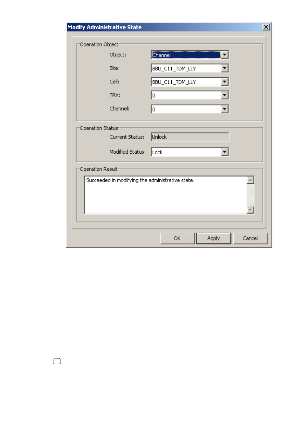
Figure 4-25 Modify Administrative State dialog box
2. Change the status of all the TRX TCHs in the cell from Unlocked to Locked. If the operation
succeeds, the Succeeded in modifying the administrative state. message is displayed in the
Operation Result area.
3. Lock the testing MS on a specific frequency. Change the state of one or two TCHs on the
frequency from Locked to Unlocked. Then, conduct the call tests on this TCH.
Step 4 Conduct the call test as follows:
1. Make a call from one MS to the other, and hook on after the conversation.
2. Make a call from one MS to a PSTN phone, and hook on after the conversation.
3. Make a call from a PSTN phone to one MS, and hook on after the conversation.
NOTE
lIt is recommended that each type of test calls be conducted for more than five times to ensure the results.
lIf time permits, it is recommended that one call test be conducted for each the channels of all the TRXs.
For detailed operations, see Step 3.
Step 5 Ensure that all calls are successful, the conversion is normal, and voice quality is clear.
4 Commissioning the BTS (Transmission Available)
BTS3900(A) GSM
Commissioning Guide
4-24 Huawei Proprietary and Confidential
Copyright © Huawei Technologies Co., Ltd.
Issue 02 (2009-04-20)

If... Then...
Mobile-originated call succeeds 1. Check the LEDs and alarms. If an alarm is
generated on the BTS side, clear the alarm.
2. If an alarm is generated on the BSC side,
contact BSC technical support engineers to
handle it.
3. After the fault is rectified, go to Step 1 to test
the CS services for another time.
Mobile-originated call succeeds, and
mobile-terminated call fails
The data configuration on the BSC side is
improper. Contact BSC technical support
engineers for troubleshooting.
Step 6 Test short message service (SMS) as follows: Use two testing MSs to send SMS messages to
each other, and ensure that all the SMS messages are successfully sent and received.
Step 7 Choose a proper operation procedure based on actual conditions.
If... Then...
Step 3 is performed 1. Repeat Step 3 through Step 6 to verify the CS services of other
TCHs on the same frequency.
2. Repeat steps Step 2 through Step 6 to test the CS services in other
logical cells at the site.
Step 3 is not performed Repeat Step 2, and Step 4 through Step 6 to verify the CS services
in other logical cells at the site.
----End
4.5.2 Commissioning PS Services
This describes how to commission PS services by website browsing and file downloading
through an MS. A laptop is required to monitor the commissioning. You need to commission
only the BTS that is configured with the GPRS or EGPRS services.
Prerequisite
lOne test MS that supports GSM and PS services is registered with the HLR.
lThe BTS cell to be checked is configured with the GPRS or EGPRS services.
lThe logical cell to be checked is activated.
lThe computer and the BSC work properly.
BTS3900(A) GSM
Commissioning Guide 4 Commissioning the BTS (Transmission Available)
Issue 02 (2009-04-20) Huawei Proprietary and Confidential
Copyright © Huawei Technologies Co., Ltd.
4-25
Procedure
Step 1 Activate the GPRS or EGPRS data service with the MS. Then, commission PS services through
multi-service testing. The PS service test involves sending multimedia message, browsing
websites, and downloading files.
Step 2 Check whether the MS can successfully send multimedia messages, browse webpages, and
download files.
If... Then...
One of the three PS service tests is
successful
The hardware on the BTS side meets the
requirements for PS services.
All the three PS service tests fail Check whether the test MS works properly, for
example, the test MS is configured with the SIM
card or the SIM card supports authentication and
encryption.
Step 3 Repeat Step 1 through Step 2 to test PS services in other cells under the BTS.
----End
4.6 Checking the BTS Environment Alarms
This describes how to check the BTS environment alarms. It also describes how to monitor the
operating environment of the BTS.
4.6.1 BTS Environment Alarm Types
This describes the various types of environment alarms of the BTS. The alarms consist of the
fire alarm, smoke alarm, infrared alarm, water alarm, temperature alarm, humidity alarm, air-
conditioner alarm, door status alarm, and burglar alarm.
4.6.2 Checking the Environment Monitoring Alarms on the LMT
This describes how to check the environment monitoring alarms. Checking the environment
monitoring alarms is implemented through simulating the environment factors that may generate
alarms, thus checking whether the physical connections of the BTS can report and clear the
alarms. Note that the BTS technical support engineers should assist in checking the Boolean
environment monitoring alarm.
4.6.1 BTS Environment Alarm Types
This describes the various types of environment alarms of the BTS. The alarms consist of the
fire alarm, smoke alarm, infrared alarm, water alarm, temperature alarm, humidity alarm, air-
conditioner alarm, door status alarm, and burglar alarm.
4 Commissioning the BTS (Transmission Available)
BTS3900(A) GSM
Commissioning Guide
4-26 Huawei Proprietary and Confidential
Copyright © Huawei Technologies Co., Ltd.
Issue 02 (2009-04-20)

NOTE
lCritical alarm: devices or resources may be unusable, and restoration should be performed at once.
lMajor alarm: The QoS of devices or resources severely deteriorates, and measures should be taken as
soon as possible.
lThe thresholds of temperature alarm and humidity alarm are subject to the local climate and terrain
conditions and should be specified on the basis of the field requirements.
Fire Alarm
The fire alarm is the environment alarm generated when the equipment room is on fire. This is
a critical alarm.
Smoke Alarm
The smoke alarm is an environment alarm generated when the smoke density in the equipment
room reaches a predefined threshold. This is a critical alarm.
Infrared Alarm
The infrared alarm is an environment alarm generated when an infrared facility is taken into the
equipment room or is in the infrared detection range of the cabinet. This is a major alarm.
Water Alarm
The water alarm is an environment alarm generated when water immersion occurs in the
equipment room. This is a major alarm.
Temperature Alarm
The temperature alarm consists of the overtemperature alarm and the undertemperature alarm.
This is a major alarm.
lThe overtemperature alarm is generated when the ambient temperature is higher than the
predefined upper threshold of the temperature.
lThe undertemperature alarm is generated when the ambient temperature is lower than the
predefined lower threshold of the temperature.
Humidity Alarm
The humidity alarm consists of the high humidity alarm and the low humidity alarm. This is a
major alarm.
lThe high humidity alarm is generated when the environment humidity is higher than the
predefined upper threshold of the humidity.
lThe low humidity alarm is generated when the environment humidity is lower than the
predefined lower threshold of the humidity.
Air-Conditioner Alarm
The air-conditioner alarm is generated when the air-conditioner is not running properly or the
AC power supply is not normal. This is a major alarm.
BTS3900(A) GSM
Commissioning Guide 4 Commissioning the BTS (Transmission Available)
Issue 02 (2009-04-20) Huawei Proprietary and Confidential
Copyright © Huawei Technologies Co., Ltd.
4-27
Door Status Alarm
The door status alarm is an environment alarm generated when the door of the equipment room
or the door of the cabinet is opened. This is a major alarm.
Burglar Alarm
The burglar alarm is generated when the infrared alarm or door status alarm occurs. This is a
critical alarm.
4.6.2 Checking the Environment Monitoring Alarms on the LMT
This describes how to check the environment monitoring alarms. Checking the environment
monitoring alarms is implemented through simulating the environment factors that may generate
alarms, thus checking whether the physical connections of the BTS can report and clear the
alarms. Note that the BTS technical support engineers should assist in checking the Boolean
environment monitoring alarm.
Context
The BTS3900 GSM supports the monitoring boards of the DEMU, DPMU, FMU, and GATM.
Besides the monitoring boards of the BTS3900 GSM, the BTS3900A GSM also supports the
APMU, FMUA, and DTCU. Table 4-1 describes the detailed configuration.
Table 4-1 Monitoring boards of the BTS3900 and the BTS3900A
Slot in
Subrack 2
0 1 2 3 4 5 6 7 8 9 1
0
1
1
1
2
1
3
1
4
1
5
1
6
1
7
BTS3900
GSM
D
E
M
U
D
E
M
U
D
P
M
U
D
P
M
U
- - - - F
M
U
F
M
U
F
M
U
F
M
U
- - - - G
A
T
M
G
A
T
M
BTS3900A
GSM
D
E
M
U
D
E
M
U
D
P
M
U
o
r
A
P
M
U
D
P
M
U
o
r
A
P
M
U
-- D
T
C
U
D
T
C
U
F
M
U
o
r
F
M
U
A
F
M
U
o
r
F
M
U
A
F
M
U
o
r
F
M
U
A
F
M
U
o
r
F
M
U
A
-- - - G
A
T
M
G
A
T
M
Procedure
lCommissioning the Boolean alarm (Door Open Alarm of the DEMU)
4 Commissioning the BTS (Transmission Available)
BTS3900(A) GSM
Commissioning Guide
4-28 Huawei Proprietary and Confidential
Copyright © Huawei Technologies Co., Ltd.
Issue 02 (2009-04-20)

Alarm switch enabled and alarm switch valid level are required to be noted when checking
the Boolean alarm both on the SMT and the LMT. The following part takes the Door Open
Alarm of the DEMU as an example to describe the procedure for testing the Boolean alarm.
NOTE
lTrigger conditions of the Door Open Alarm: When the cabinet door of the BTS is open, the
DEMU reports Door Open Alarm; when the cabinet door of the BTS is closed, the Door Open
Alarm is cleared.
lDisable the Door Open Alarm and configure the alarm valid level: When the Door Open
Alarm is disabled, the DEMU does not report the Door Open Alarm. In other words, the Door
Open Alarm is shielded. Alarm valid level configuration specifies the valid level of the door
sensor alarm, which is determined by the attribute of the field Gate Magnetism.
lOn the LMT, choose Alarm Maintenance > Browse Alarm. Check the alarm information in
the displayed Browse Alarm dialog box.
1. Check whether the Door Open Alarm can be reported normally by opening the
cabinet door of the BTS and be cleared normally by closing the cabinet door of the
BTS.
–If the alarm can be reported and cleared normally, end the checking task.
–If the alarm cannot be reported, go to Step 2 to check the data configuration of the
Gate Magnetism.
TIP
If the valid level of the door sensor alarm on site is inconsistent with the valid level of the door
sensor alarm based on the data configuration, the reported alarms are opposite. For example,
if the valid level of the door sensor alarm on site is high and the configured valid level is low,
then:
When the cabinet door of the BTS is closed, the DEMU reports the Door Open Alarm; when
the cabinet door of the BTS is open, the Door Open Alarm is cleared.
2. In the BSC6000 Local Maintenance Terminal window, right-click the site to be
queried and choose Configure Site Board Attributes. The Configure Site Board
Attributes dialog box is displayed.
3. Click Configure Site Board Attributes, the Site Device Attributes dialog box is
displayed.
4. Right-click DEMU, choose Configure Site Board Attributes. The Basic Attributes
of Site Board dialog box is displayed.
5. Click the Configure Site Board Attributes tab. Then set Board Parameter
Configuration Enabled to Yes. Click Special Alarm Switch Enabled to check
whether Gate Magnetism(Disabled) is selected, as shown in Figure 4-26.
–In normal conditions, the check box Gate Magnetism(Disabled) is deselected,
which means it is enabled and the Door Open Alarm is reported once the alarm is
generated.
–If the check box Gate Magnetism(Disabled) is selected, deselect the check box.
BTS3900(A) GSM
Commissioning Guide 4 Commissioning the BTS (Transmission Available)
Issue 02 (2009-04-20) Huawei Proprietary and Confidential
Copyright © Huawei Technologies Co., Ltd.
4-29
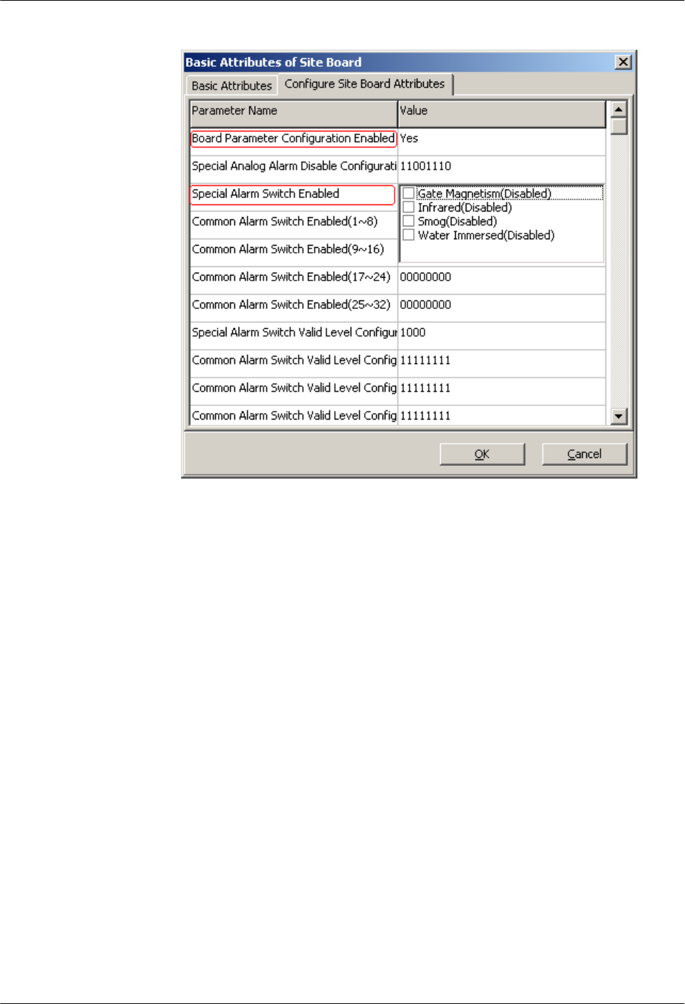
Figure 4-26 Basic Attributes of Site Board (1)
6. Click Special Alarm Switch Valid Level Configuration in the Basic Attributes of
Site Board dialog box. Check whether the configuration of the Gate Magnetism(Low
Level) is consistent with the actual alarm switch valid level of the Gate Magnetism,
as shown in Figure 4-27. If the alarm switch valid level of the field Gate Magnetism
is high level, then
–In normal conditions, the check box Gate Magnetism(Low Level) is deselected,
which means the Door Open Alarm is reported at a high level.
–If the check box Gate Magnetism(Low Level) is selected, deselect the check box.
4 Commissioning the BTS (Transmission Available)
BTS3900(A) GSM
Commissioning Guide
4-30 Huawei Proprietary and Confidential
Copyright © Huawei Technologies Co., Ltd.
Issue 02 (2009-04-20)
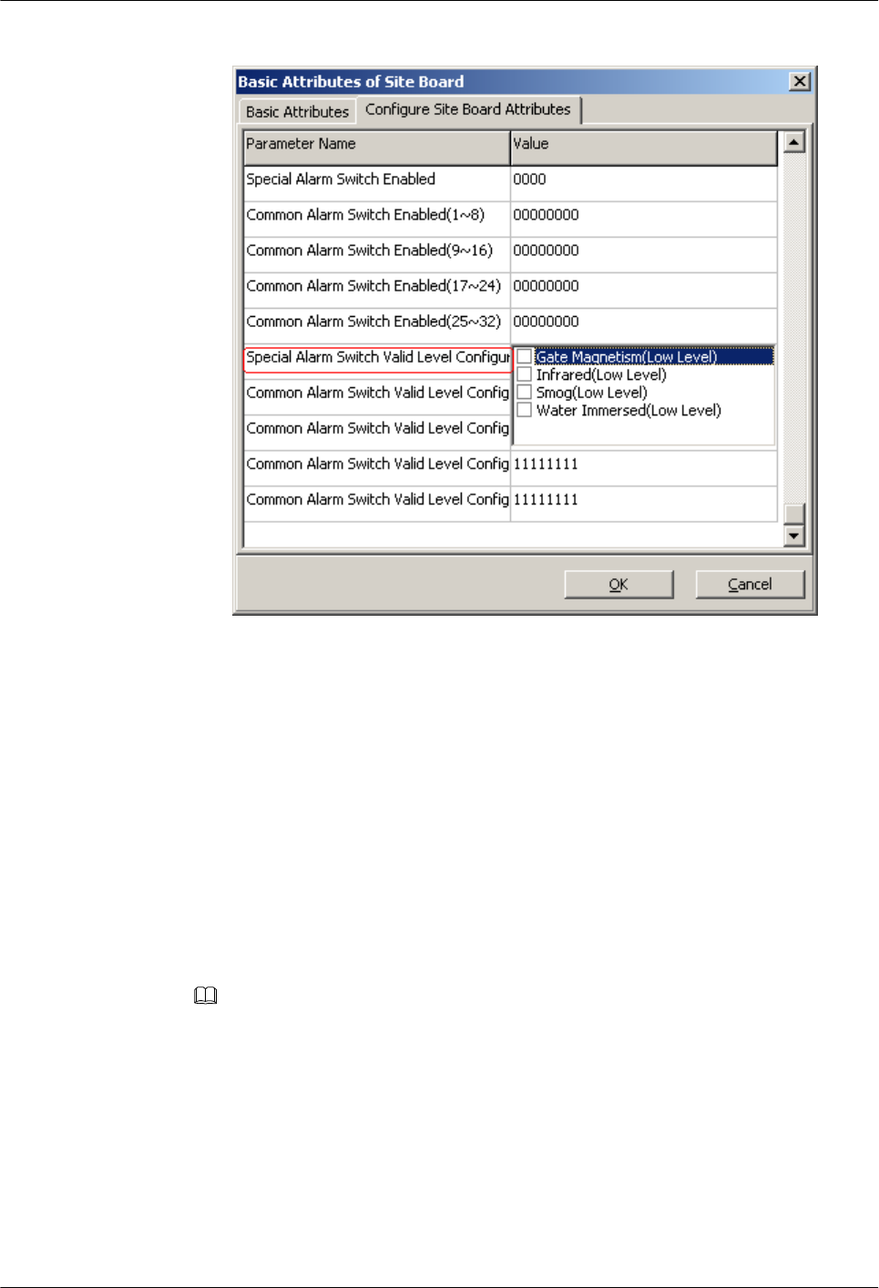
Figure 4-27 Basic Attributes of Site Board (2)
7. When the checking is complete, check whether the Door Open Alarm can be reported
normally by opening the cabinet door of the BTS and be cleared normally by closing
the cabinet door of the BTS.
–If the alarm can be reported and cleared normally, end the checking task.
–If the alarm cannot be reported, reconnect the related monitoring signal cable. For
details, see the BTS3900 Quick Installation Guide or the BTS3900A Quick
Installation Guide.
lCommissioning the alarm reported through the RS485 port (temperature monitoring alarm
of the DTCU)
The following part takes the temperature monitoring of the DTCU as an example to describe
the commissioning of the temperature monitoring alarm of the monitoring board.
NOTE
lTrigger conditions of Temperature Too High Alarm: When the actual temperature of DTCU exceeds
the High Temperature Alarm Threshold, the DTCU reports the Temperature Too High Alarm.
lTrigger condition of Temperature Too Low Alarm: When the actual temperature of DTCU exceeds
the Low Temperature Alarm Threshold, the DTCU reports the Temperature Too Low Alarm.
lOn the LMT, choose Alarm Maintenance > Browse Alarm. Check the alarm information in the
displayed Browse Alarm dialog box.
1. On the LMT, query the ambient temperature of the BTS DTCU.
(1) In the BSC6000 Local Maintenance Terminal window, select the site to be
queried. Right-click the monitoring board to be queried on the Site Device
BTS3900(A) GSM
Commissioning Guide 4 Commissioning the BTS (Transmission Available)
Issue 02 (2009-04-20) Huawei Proprietary and Confidential
Copyright © Huawei Technologies Co., Ltd.
4-31
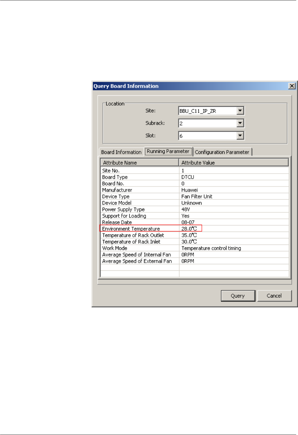
Panel tab page and choose Query Board Information. The Query Board
Information dialog box is displayed.
(2) Click the Running Parameter tab, and then click Query on the Running
Parameter tab. The query is successful, and the running status of the board is
displayed in the dialog box. The current Environment Temperature is
28.0℃, as shown in Figure 4-28.
Figure 4-28 Query Board Information dialog box
2. On the LMT, set the High Temperature Alarm Threshold to a value lower than the
normal temperature to trigger the alarm.
(1) In the BSC6000 Local Maintenance Terminal window, right-click the site to
be queried and choose Configure Site Board Attributes. The Configure Site
Board Attributes dialog box is displayed.
(2) Click Configure Site Board Attributes, the Site Device Attributes dialog box
is displayed.
(3) Right-click DTCU and choose Configure Site Board Attributes. The Basic
Attributes of Site Board dialog box is displayed.
4 Commissioning the BTS (Transmission Available)
BTS3900(A) GSM
Commissioning Guide
4-32 Huawei Proprietary and Confidential
Copyright © Huawei Technologies Co., Ltd.
Issue 02 (2009-04-20)
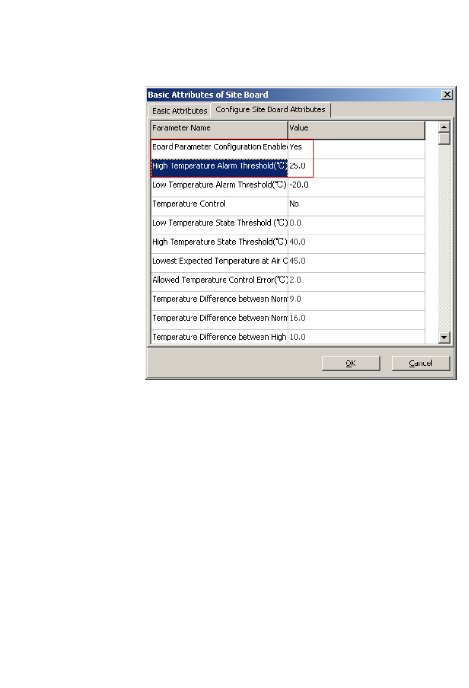
(4) Click Configure Site Board Attributes tab. Then set Board Parameter
Configuration Enabled to Yes and set High Temperature Alarm Threshold
to 25.0, as shown in Figure 4-29.
Figure 4-29 Basic Attributes of Site Board (3)
(5) Click OK to complete the setting of the temperature alarm threshold.
3. Check the alarm information of the DTCU. For details, see 4.4 Checking the Alarm
Information of the BTS (on the LMT). If the DTCU reports Temperature Too
High Alarm, the ambient temperature alarm can be reported normally. If the alarm
cannot be reported normally, reconnect the related monitoring signal cables. For
details, see the Quick Installation Guide.
4. Set High Temperature Alarm Threshold again to clear Temperature Too High
Alarm. For details, see Step 2.
----End
BTS3900(A) GSM
Commissioning Guide 4 Commissioning the BTS (Transmission Available)
Issue 02 (2009-04-20) Huawei Proprietary and Confidential
Copyright © Huawei Technologies Co., Ltd.
4-33

5 Commissioning the BTS (Transmission
Unavailable)
About This Chapter
This describes how to commission the BTS in the transmission unavailable scenario. The
commissioning of the BTS consists of two phases. In the initial phase of the commissioning, the
transmission cable between the BSC and the BTS is not properly connected. Commission the
BTS at the local end. In the later phase of the commissioning, the transmission cable between
the BSC and the BTS is properly connected. Commission the BTS on the BSC side.
5.1 Starting the Site Maintenance Terminal
This describes how to start the SMT. To start the SMT, you need to set the IP address of the
SMT PC, connect the SMT PC to the BTS, and then log in to the SMT.
5.2 Configuring the Basic Data of the BTS
This describes how to configure the basic data of the BTS such as the BTS boards and logical
objects of the site. If the commissioning is performed on the BTS side, other commissioning
tasks can be performed only after the configuration of the basic data of the BTS.
5.3 Checking the Active Software Version on the SMT
This describes how to check the software versions of the boards and modules in the BTS in the
Site Maintenance Terminal System window.
5.4 Checking the Transmission Between the BBU and RFU on the BTS Side
This describes how to check the transmission between the BBU and the RFU on the BTS side.
By checking the link status of the BBU and RFU, you can rectify the fault caused by abnormal
connection, thus ensuring normal communication between the BBU and the RFU.
5.5 Checking the Running Status of the BTS
This describes how to check the running status of the BTS. Check the running status of the BTS
involves checking the status of LEDs and alarm information on the SMT.
5.6 Checking the Hardware Connection of the BTS
This describes how to check the hardware connection of the BTS by checking the connection
of power cables, grounding cables, and all kinds of signal cables.
BTS3900(A) GSM
Commissioning Guide 5 Commissioning the BTS (Transmission Unavailable)
Issue 02 (2009-04-20) Huawei Proprietary and Confidential
Copyright © Huawei Technologies Co., Ltd.
5-1

5.1 Starting the Site Maintenance Terminal
This describes how to start the SMT. To start the SMT, you need to set the IP address of the
SMT PC, connect the SMT PC to the BTS, and then log in to the SMT.
5.1.1 Setting the IP Address of the Site Maintenance Terminal PC
This describes how to set the IP address of the SMT PC to the same network segment as the IP
address (192.168.0.72/255.255.255.0) of the BTS.
5.1.2 Locally Connecting the SMT PC to the BTS
This describes how to connect the Site Maintenance Terminal (SMT) PC to the ETH port on the
main control module of the BTS through an Ethernet cable. After they are connected, you can
operate and maintain the BTS on the SMT.
5.1.3 Logging in to the BTS at the Local End
This describes how to log in to the BTS. You can run the SMT to directly log in to the BTS at
the local end.
5.1.1 Setting the IP Address of the Site Maintenance Terminal PC
This describes how to set the IP address of the SMT PC to the same network segment as the IP
address (192.168.0.72/255.255.255.0) of the BTS.
Prerequisite
The TCP/IP protocol is installed on the SMT PC.
Procedure
Step 1 To set the IP address of the PC, perform the following steps where the Windows XP operating
system is taken as an example: On Windows XP, choose Start > Setting > Control Panel .
Step 2 Double-click Network Connections in the displayed Control Panel window. Right-click Local
Area Connection in the displayed dialog box.
Step 3 Choose Properties from the shortcut menu. The Local Area Connection Properties dialog
box is displayed.
Step 4 Select Internet Protocol (TCP/IP), and click Properties. The Internet Protocol (TCP/IP)
Properties dialog box is displayed.
Step 5 Select Use the following IP address.
Step 6 Enter the correct IP address, subnet mask, and default gateway. Ensure that the IP address of the
SMT PC is in the same network segment as the IP addresses (192.168.0.72/255.255.255.0) of
the BTS so that a maintenance channel on the BTS side can be established.
Step 7 Click OK to complete the settings.
----End
5 Commissioning the BTS (Transmission Unavailable)
BTS3900(A) GSM
Commissioning Guide
5-2 Huawei Proprietary and Confidential
Copyright © Huawei Technologies Co., Ltd.
Issue 02 (2009-04-20)

5.1.2 Locally Connecting the SMT PC to the BTS
This describes how to connect the Site Maintenance Terminal (SMT) PC to the ETH port on the
main control module of the BTS through an Ethernet cable. After they are connected, you can
operate and maintain the BTS on the SMT.
Prerequisite
The IP address and subnet mask of the SMT PC are set correctly. The IP address is in the same
network segment as the IP address (192.168.0.72/255.255.255.0) of the BTS.
Procedure
Step 1 Connect the SMT PC to the BTS through an Ethernet cable. One end is connected to the ETH
port on the main control board of the basic cabinet, and the other end is connected to the Ethernet
port on the SMT PC (usually a portable PC).
Step 2 Open the MS-DOS Prompt dialog box.
lIf the PC is Windows 2000/XP operating system based, choose Start > Run on the SMT. In
the Run dialog box, run the cmd command. The MS-DOS Prompt dialog box is displayed.
Step 3 Run ping 192.168.0.72 to verify the network connection between the computer and the BTS.
NOTE
The IP address of the BTS is 192.168.0.72.
lIf the information similar to that in the following example is returned, the SMT PC and the
BBU can communicate normally.
Pinging 192.168.0.72 with 32 bytes of data:
Pinging 192.168.0.72 with 32 bytes of data:
Reply from 192.168.0.72: bytes=32 time=1ms TTL=253
Reply from 192.168.0.72: bytes=32 time=1ms TTL=253
Reply from 192.168.0.72: bytes=32 time=1ms TTL=253
Reply from 192.168.0.72: bytes=32 time=1ms TTL=253
Ping statistics for 192.168.0.72:
Packets: Sent = 4, Received = 4, Lost = 0 (0% loss),
Approximate round trip times in milli-seconds:
Minimum = 1ms, Maximum = 1ms, Average = 1ms
lIf the SMT PC and the BBU fail to communicate, the possible reason is as follows:
–The GTMU is faulty.
–The Ethernet cable is faulty, or its connectors are loose.
–The Ethernet port on the SMT PC is faulty.
–The BTS is resetting.
–The IP address is incorrect.
----End
5.1.3 Logging in to the BTS at the Local End
This describes how to log in to the BTS. You can run the SMT to directly log in to the BTS at
the local end.
Prerequisite
lThe SMT PC is properly connected to the BTS.
BTS3900(A) GSM
Commissioning Guide 5 Commissioning the BTS (Transmission Unavailable)
Issue 02 (2009-04-20) Huawei Proprietary and Confidential
Copyright © Huawei Technologies Co., Ltd.
5-3
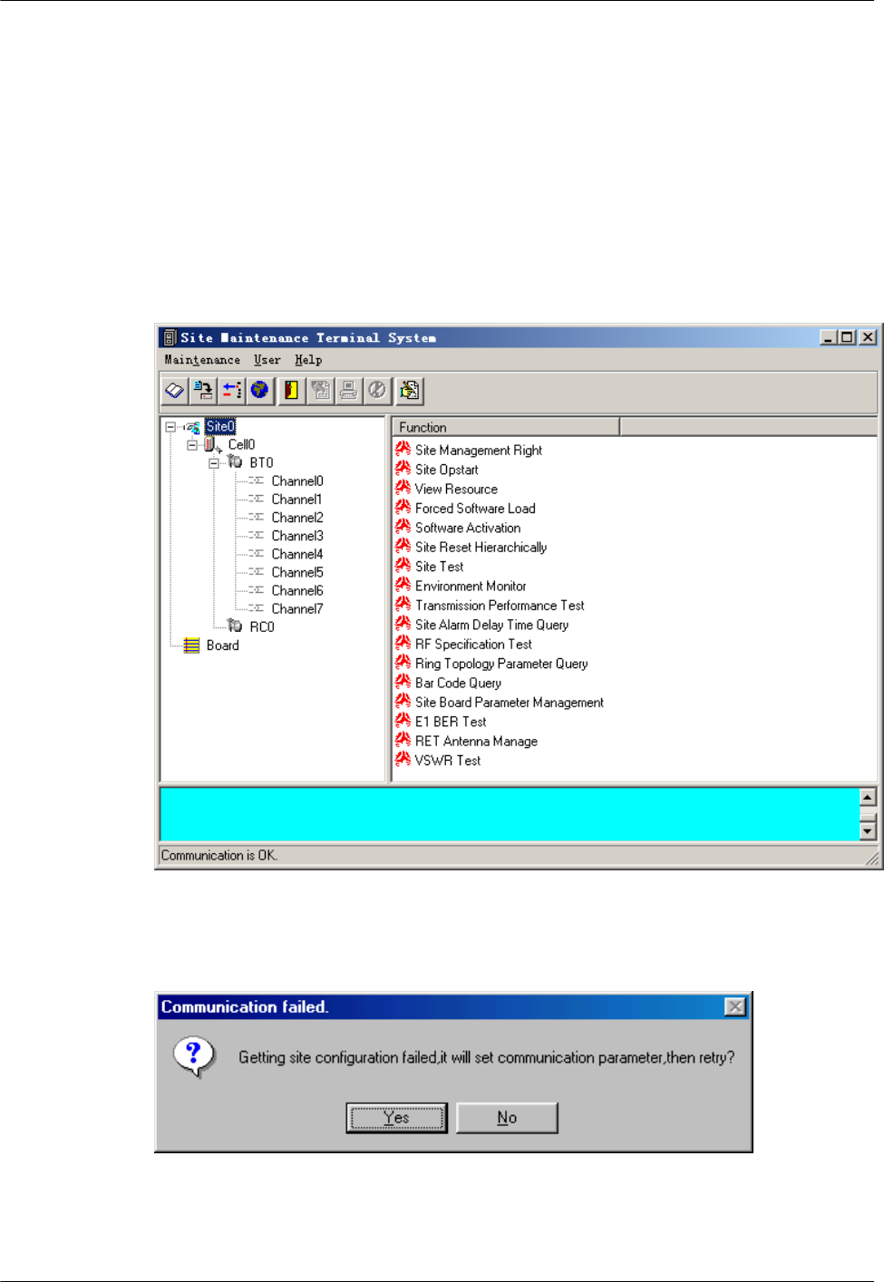
lThe latest software of the SMT is installed in the SMT PC.
Procedure
Step 1 Start the SMT.
lIf the SMT PC communicates with the BTS normally, a window is displayed, as shown in
Figure 5-1. The SMT is successfully started.
lIf the SMT PC cannot communicate with the BTS, the Communication failed dialog box
is displayed, as shown in Figure 5-2. Go to Step 2.
Figure 5-1 Site Maintenance Terminal system window
Figure 5-2 Communication failed dialog box
Step 2 Click Yes.
5 Commissioning the BTS (Transmission Unavailable)
BTS3900(A) GSM
Commissioning Guide
5-4 Huawei Proprietary and Confidential
Copyright © Huawei Technologies Co., Ltd.
Issue 02 (2009-04-20)
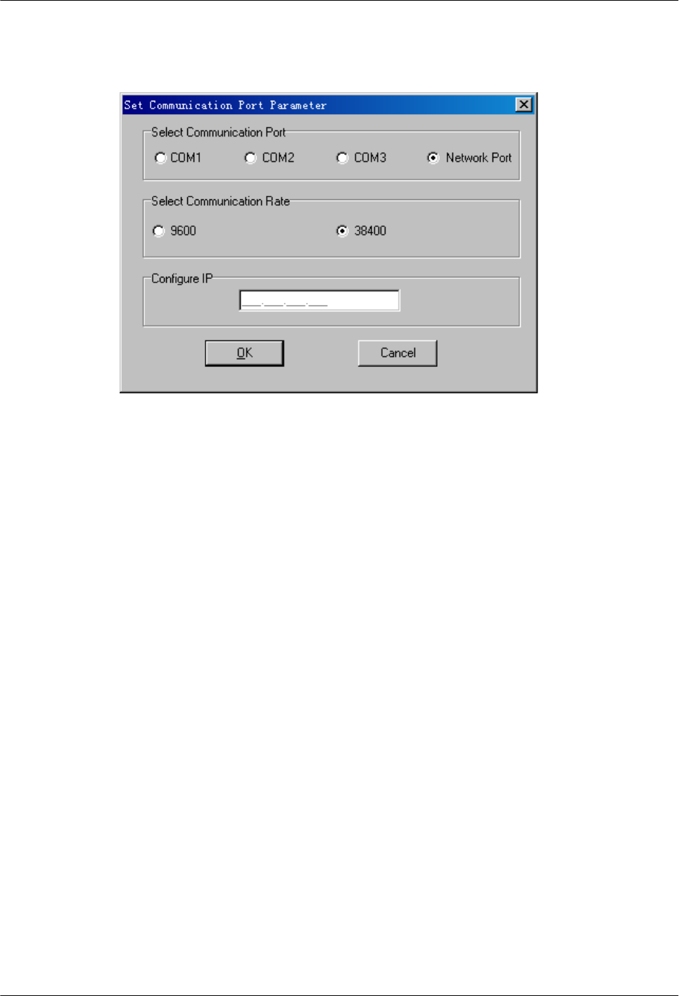
The Set Communication Port Parameter dialog box is displayed, as shown in Figure 5-3.
Figure 5-3 Set Communication Port Parameter dialog box
Step 3 In the Select Communication Port area, click Network Port. In the Configure IP area, set the
IP address to 192.168.0.72.
Step 4 Click OK.
The Site Maintenance Terminal System window is displayed, as shown in Figure 5-1.
Step 5 In the Site Maintenance Terminal System window, click User, and select User Login. Enter
User Name (Omc by default) and User Password (omc by default). Logging in to the BTS
succeeds.
----End
5.2 Configuring the Basic Data of the BTS
This describes how to configure the basic data of the BTS such as the BTS boards and logical
objects of the site. If the commissioning is performed on the BTS side, other commissioning
tasks can be performed only after the configuration of the basic data of the BTS.
5.2.1 Obtaining the Site Management Rights
This describes how to obtain the site management rights. Before configuring the BTS board and
site logical objects, you must obtain the site management rights after logging into the BTS at
the local end.
5.2.2 Configuring the Boards of the BTS on the SMT
This describes how to configure the TRX boards and other boards of the BTS.
5.2.3 Configuring Logical Objects of the BTS on the SMT
This describes how to configure logical objects of the BTS. The BTS logical object configuration
consists of the cell configuration, carrier binding, and activation of cell configuration data.
BTS3900(A) GSM
Commissioning Guide 5 Commissioning the BTS (Transmission Unavailable)
Issue 02 (2009-04-20) Huawei Proprietary and Confidential
Copyright © Huawei Technologies Co., Ltd.
5-5
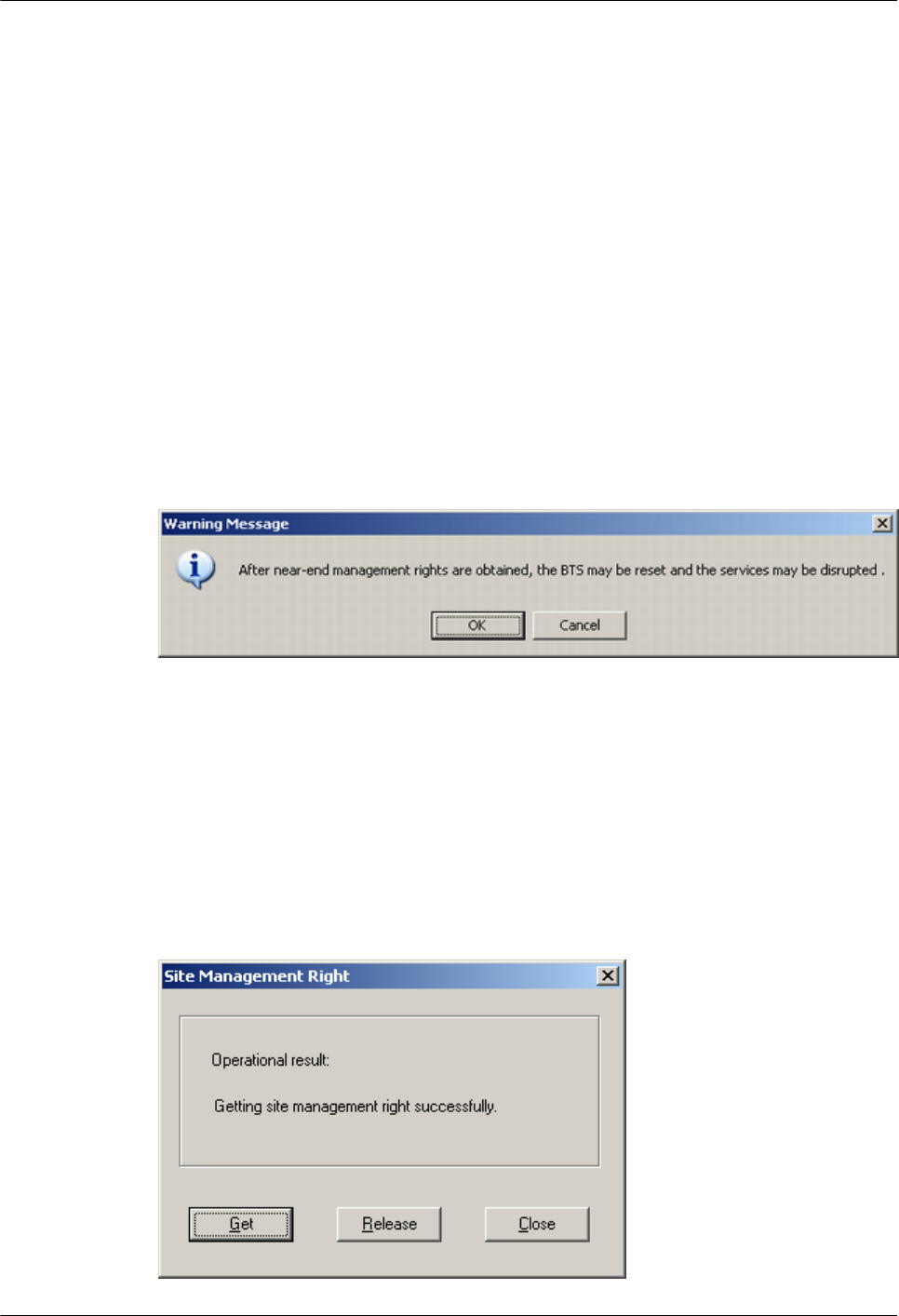
5.2.1 Obtaining the Site Management Rights
This describes how to obtain the site management rights. Before configuring the BTS board and
site logical objects, you must obtain the site management rights after logging into the BTS at
the local end.
Prerequisite
You have logged in to the BTS successfully through the SMT.
Procedure
Step 1 In the Site Maintenance Terminal System window, select Site, and double-click Site
Management Right.
The Site Management Right dialog box is displayed.
Step 2 Click Obtain. The Warning Message dialog box is displayed, as shown in Figure 5-4.
Figure 5-4 Warning message for obtaining the site management right
Step 3 Click OK, and wait for the response.
lIf the obtaining succeeds, a dialog box is displayed, as shown in Figure 5-5.
lIf the engineers are configuring or managing the BTS data on the LMT, you cannot obtain
the site management rights successfully. In this case, wait till the engineers finish the
operation on the LMT, and then repeat Step 2 and Step 3 to obtain the site management
rights.
Figure 5-5 Site Management Right dialog box
5 Commissioning the BTS (Transmission Unavailable)
BTS3900(A) GSM
Commissioning Guide
5-6 Huawei Proprietary and Confidential
Copyright © Huawei Technologies Co., Ltd.
Issue 02 (2009-04-20)
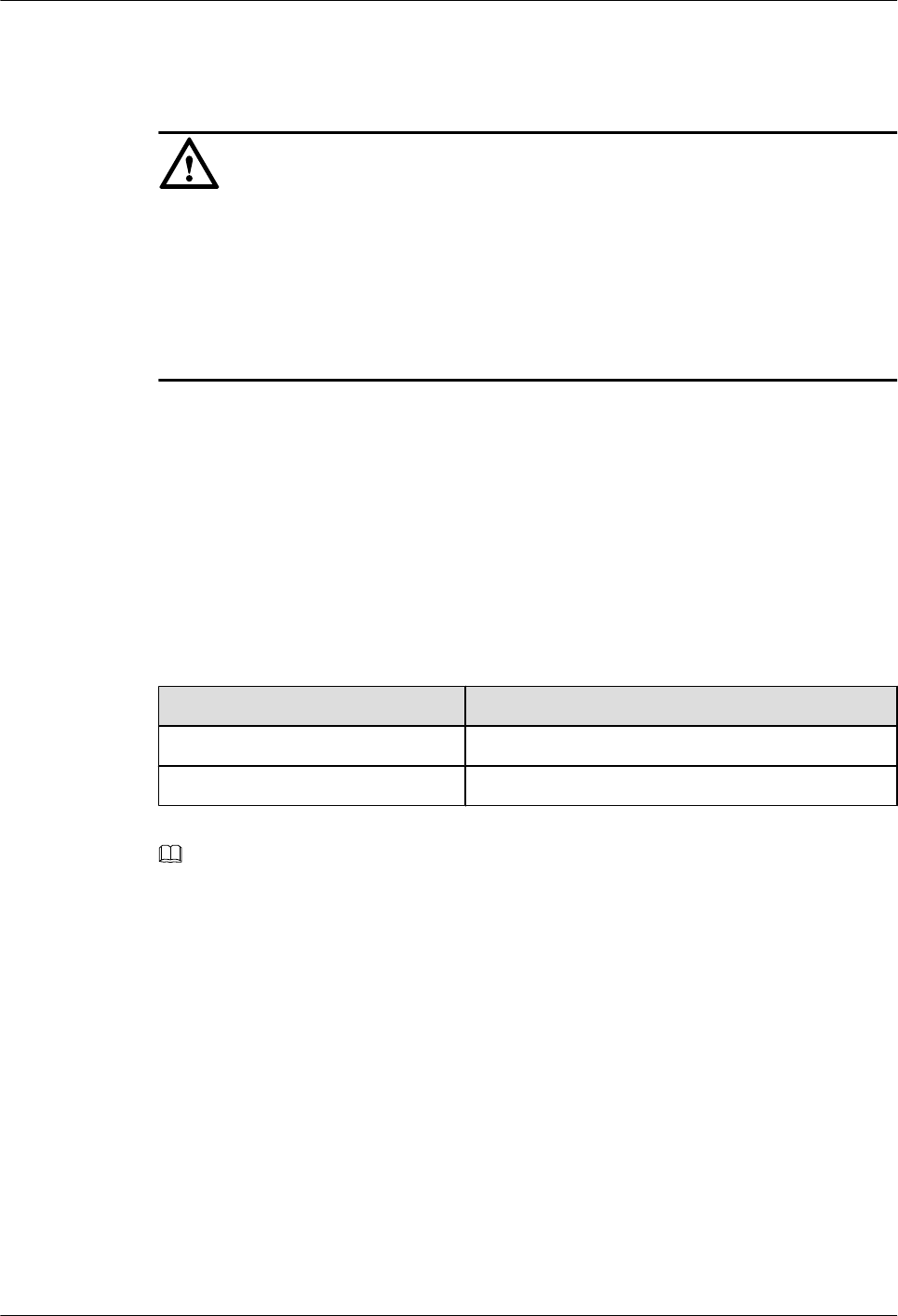
Step 4 Click Close to close the Site Management Right dialog box.
CAUTION
After the commissioning task in the transmission unavailable scenario is complete, you should
release the site management rights. Otherwise, the BTS cannot be monitored on the LMT in
fifteen minutes.
The procedure for releasing the site management rights is as follows:
Click Release in the Site Management Right dialog box. When Releasing site management
right successfully. is displayed, click Close to close the dialog box.
----End
5.2.2 Configuring the Boards of the BTS on the SMT
This describes how to configure the TRX boards and other boards of the BTS.
Context
Table 5-1 shows the types of TRXs that can be configured on the BTS3900 GSM or BTS3900A
GSM.
Table 5-1 TRX types configured on the BTS3900 GSM or the BTS3900A GSM
BTS Type TRX Type
BTS3900 GSM DRRU, DRFU, GRRU, and GRFU
BTS3900A GSM DRRU, DRFU, GRRU, and GRFU
NOTE
The following description takes one DRFU of the CPRI0 port as an example to describe the configuration
of the TRX board. One DRFU of the CPRI0 port is configured on the first level of the SPF0 link.
Procedure
Step 1 Click Board in the navigation pane.
The Board Configuration and Board Management windows are displayed.
Step 2 Double-click Board Configuration.
The Board Configuration window is displayed, as shown in Figure 5-6.
BTS3900(A) GSM
Commissioning Guide 5 Commissioning the BTS (Transmission Unavailable)
Issue 02 (2009-04-20) Huawei Proprietary and Confidential
Copyright © Huawei Technologies Co., Ltd.
5-7
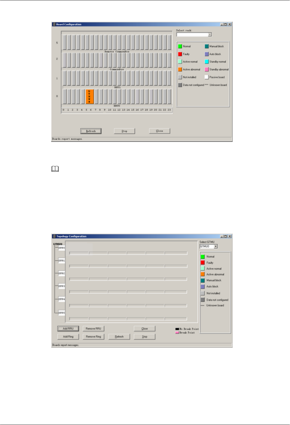
Figure 5-6 Board Configuration window
NOTE
In the transmission unavailable scenario, no site information is configured, thus, there is only the GTMU
in the Board Configuration window. The status of the GTMU is Active abnormal.
Step 3 Double-click GTMU.
The Topology Configuration window is displayed, as shown in Figure 5-7.
Figure 5-7 Topology Configuration window
Step 4 Click Add RRU.
Set the parameters in the Deploy DRRU dialog box, as shown in Figure 5-8. Set Card Type
to DRFU, Card No. to 0, SFP No. to 0, and Hop No. to 1. These values are taken only as an
example in this section.
5 Commissioning the BTS (Transmission Unavailable)
BTS3900(A) GSM
Commissioning Guide
5-8 Huawei Proprietary and Confidential
Copyright © Huawei Technologies Co., Ltd.
Issue 02 (2009-04-20)
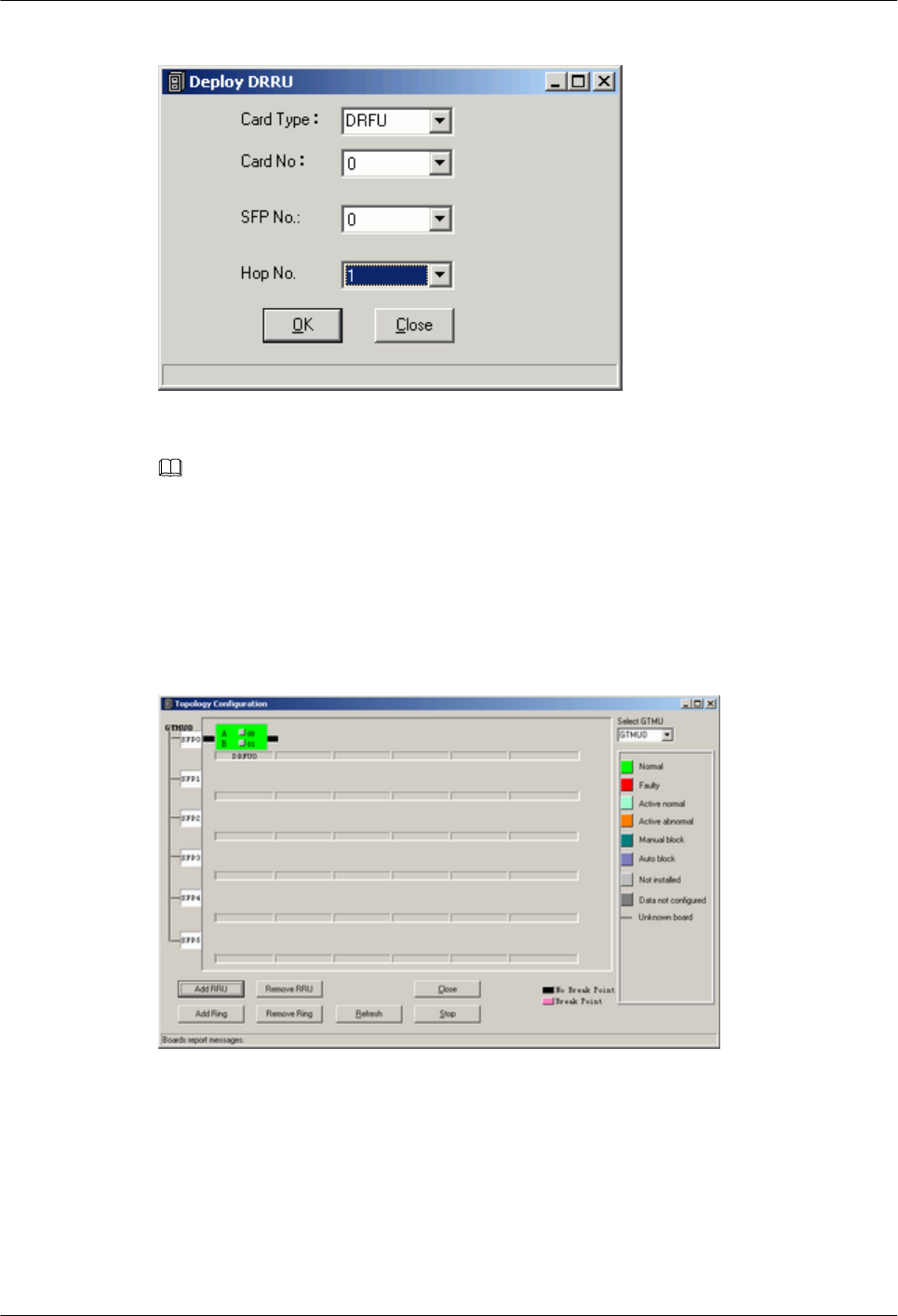
Figure 5-8 Deploy DRRU dialog box
NOTE
Card Type refers to the DRRU, DRFU, MRRU, GRRU, MRFU, or GRFU. The card number starts from
0 in sequence. The SFP number ranges from 0 to 5 and each number refers to the SFP port where the board
is configured. The hop number ranges from 1 to 6 and each number refers to the level of the TRXs under
the same SFP number.
Step 5 ClickOK. The configuration of the RF module is complete.
Figure 5-9 shows the Topology Configuration window.
Figure 5-9 Topology Configuration window
Step 6 Click Close to return to the Board Configuration window. Right-click the slot where the board
is configured, and choose the board to be configured from the shortcut menu.
Configure the APMU/DPMU, FMU, and GATM as shown in Figure 5-10.
BTS3900(A) GSM
Commissioning Guide 5 Commissioning the BTS (Transmission Unavailable)
Issue 02 (2009-04-20) Huawei Proprietary and Confidential
Copyright © Huawei Technologies Co., Ltd.
5-9
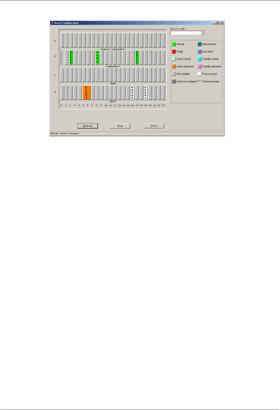
Figure 5-10 Board Configuration window
Step 7 Set the parameters: On the SMT, the parameter of DEMU cannot be set. The parameters of
DEMU and DPMU are set by default, therefore, no parameter setting is required.
Step 8 Configure the APMU: The APMU is added for the BTS3900A GSM. Perform the following
steps to configure the new types of APMU, such as APM100 and APM30.
1. Click Board in the navigation pane.
The Board Configuration and Board Management windows are displayed.
2. Double-click Board Management. The Board Management window is displayed.
3. In the Board Management window, right-click APMU, and then click Parameter
Management.
The Parameter Management dialog box is displayed.
4. In the Parameter Management dialog box, click Parameter Set. Select APM30 or other
boards under APMU Type according to the configuration data, as shown in Figure 5-11.
5 Commissioning the BTS (Transmission Unavailable)
BTS3900(A) GSM
Commissioning Guide
5-10 Huawei Proprietary and Confidential
Copyright © Huawei Technologies Co., Ltd.
Issue 02 (2009-04-20)
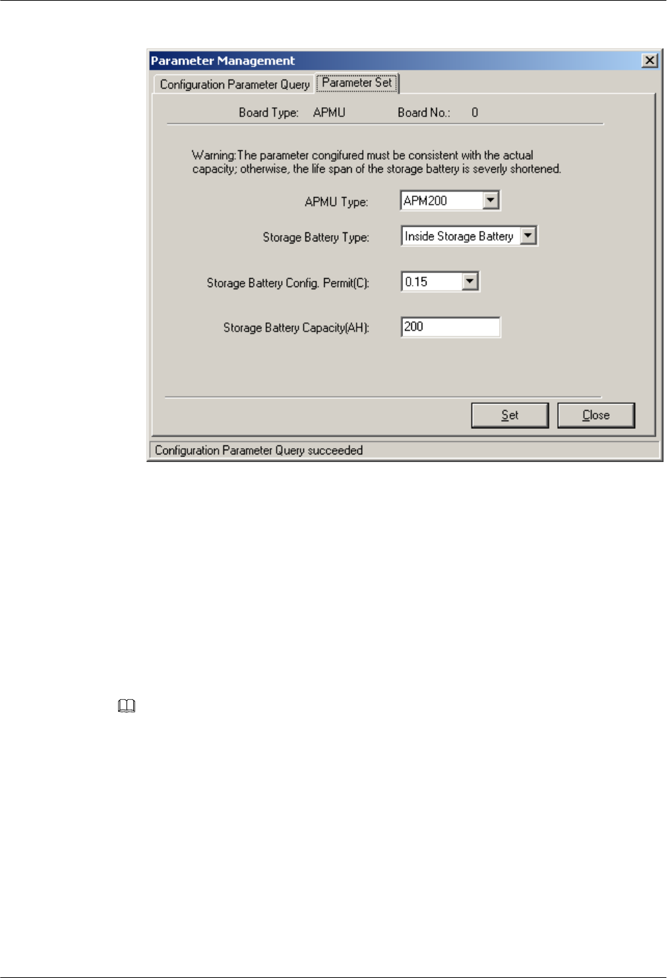
Figure 5-11 Parameter Management dialog box
Step 9 Click Close to end the board configuration of the BTS.
----End
5.2.3 Configuring Logical Objects of the BTS on the SMT
This describes how to configure logical objects of the BTS. The BTS logical object configuration
consists of the cell configuration, carrier binding, and activation of cell configuration data.
Context
NOTE
The following part describes the configuration and binding of carriers based on one DRFU configured with
two carriers.
Procedure
Step 1 Add a cell. Click Site0, and double-click Site Configuration in the Function area.
The Site Configuration dialog box is displayed, as shown in Figure 5-12.
BTS3900(A) GSM
Commissioning Guide 5 Commissioning the BTS (Transmission Unavailable)
Issue 02 (2009-04-20) Huawei Proprietary and Confidential
Copyright © Huawei Technologies Co., Ltd.
5-11
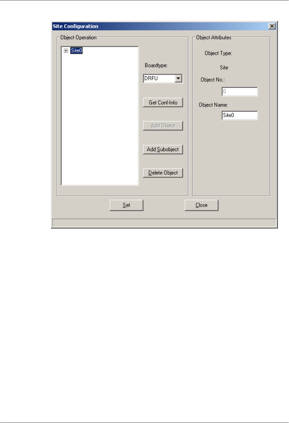
Figure 5-12 Site Configuration dialog box (1)
Step 2 Click Site0, and then click Add Subobject. In the Object Attributes area, specify Object
No. and Object Name.
In the Object Operation area, Cell0 is added, as shown in Figure 5-13.
5 Commissioning the BTS (Transmission Unavailable)
BTS3900(A) GSM
Commissioning Guide
5-12 Huawei Proprietary and Confidential
Copyright © Huawei Technologies Co., Ltd.
Issue 02 (2009-04-20)

Figure 5-13 Site Configuration dialog box (2)
Step 3 Bind the carrier. Click Cell0, and select the TRX to be configured in the Boardtype drop-down
list box. Set the board type to DRFU, as shown in Figure 5-14.
BTS3900(A) GSM
Commissioning Guide 5 Commissioning the BTS (Transmission Unavailable)
Issue 02 (2009-04-20) Huawei Proprietary and Confidential
Copyright © Huawei Technologies Co., Ltd.
5-13
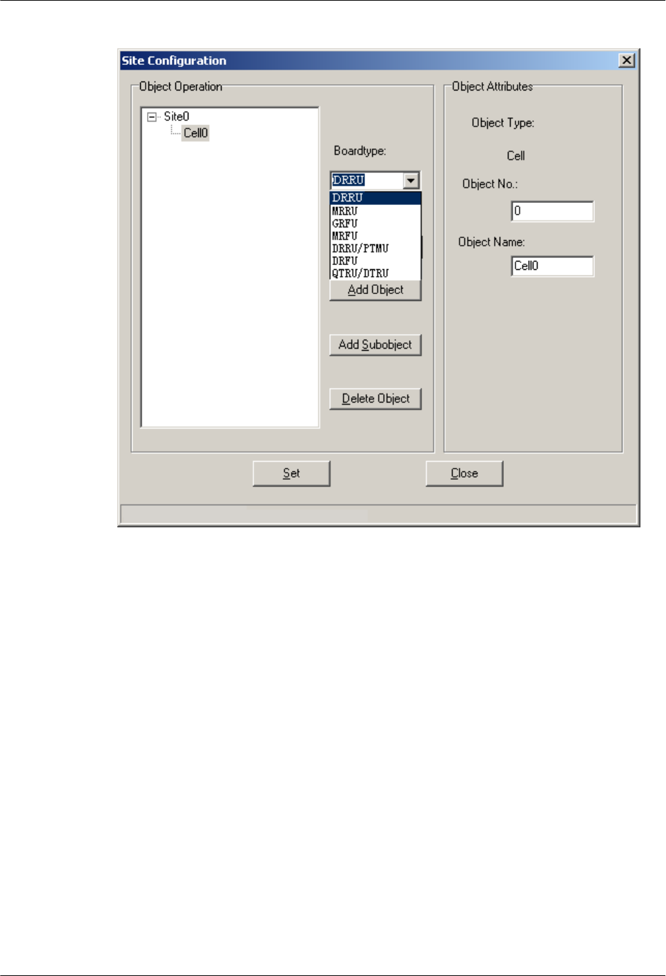
Figure 5-14 Site Configuration dialog box (3)
Step 4 Click Add Subobject. In the Object Attributes area, specify Object No., Object Name, Board
No., and Pass No.. Carrier0 is added in the Object Operation area. The carrier is bound to
pass 0 of the TRX whose board number is 0, as shown in Figure 5-15. Pass 0 is also called
carrier A. The number of paths at an RFU depends on the number of carriers configured for the
RFU.
5 Commissioning the BTS (Transmission Unavailable)
BTS3900(A) GSM
Commissioning Guide
5-14 Huawei Proprietary and Confidential
Copyright © Huawei Technologies Co., Ltd.
Issue 02 (2009-04-20)
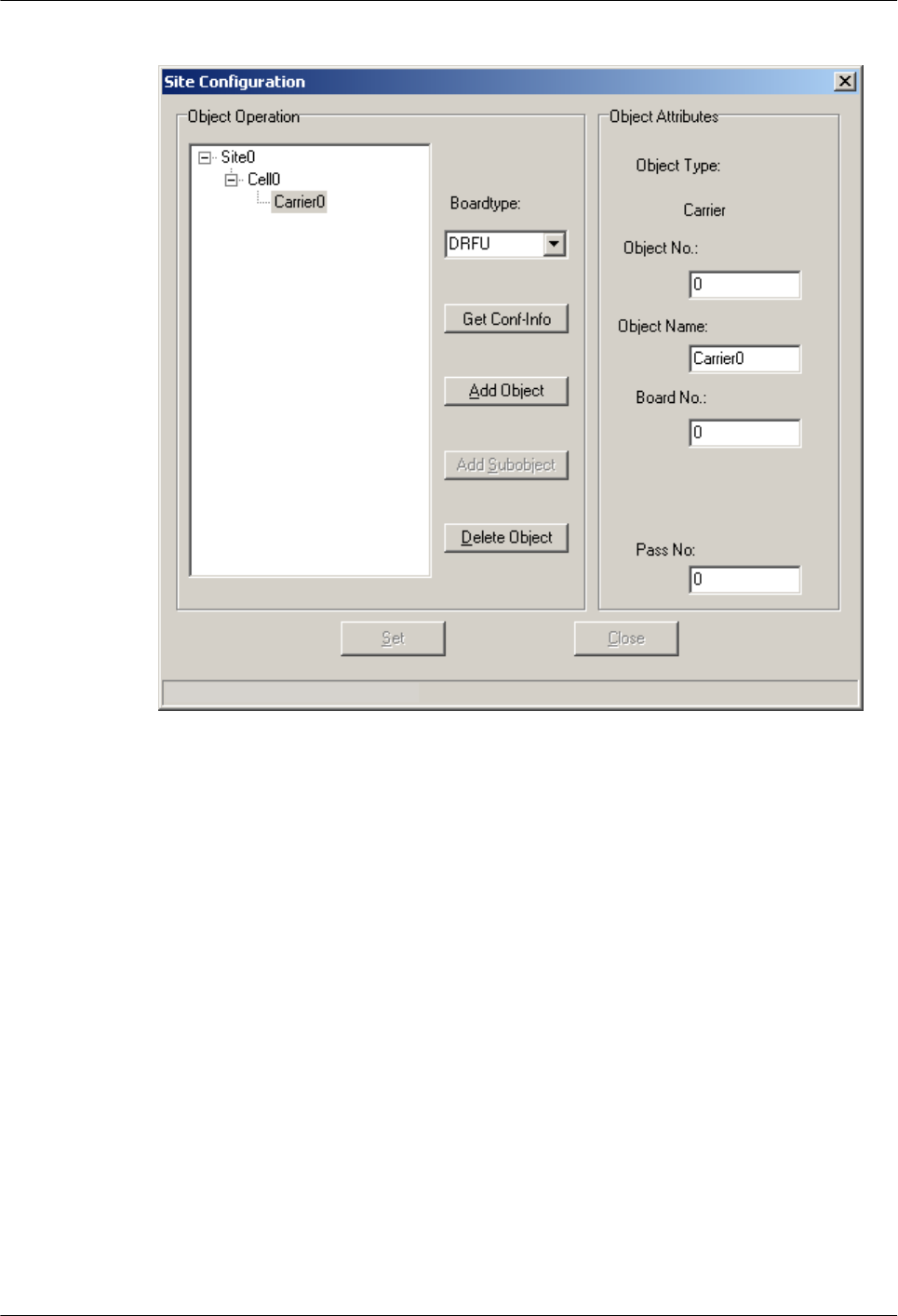
Figure 5-15 Site Configuration dialog box (4)
Step 5 Configure the second carrier: Set Object Name to Carrier1, Board No. to 0, and Pass No. to
1, as shown in Figure 5-16. The DRFU 0 is configured with two carriers.
BTS3900(A) GSM
Commissioning Guide 5 Commissioning the BTS (Transmission Unavailable)
Issue 02 (2009-04-20) Huawei Proprietary and Confidential
Copyright © Huawei Technologies Co., Ltd.
5-15
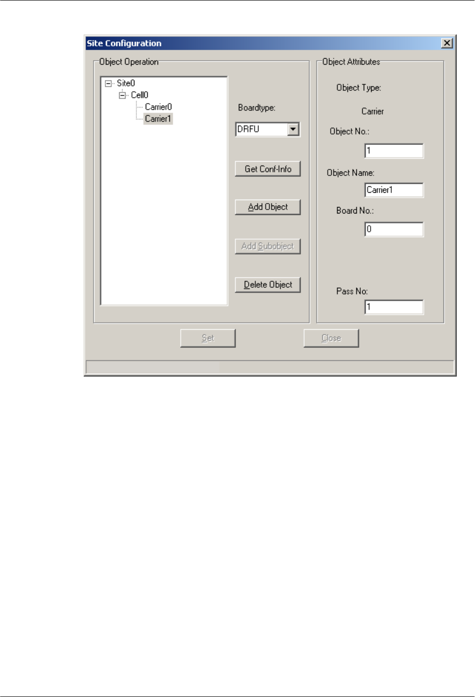
Figure 5-16 Site Configuration dialog box (5)
5 Commissioning the BTS (Transmission Unavailable)
BTS3900(A) GSM
Commissioning Guide
5-16 Huawei Proprietary and Confidential
Copyright © Huawei Technologies Co., Ltd.
Issue 02 (2009-04-20)
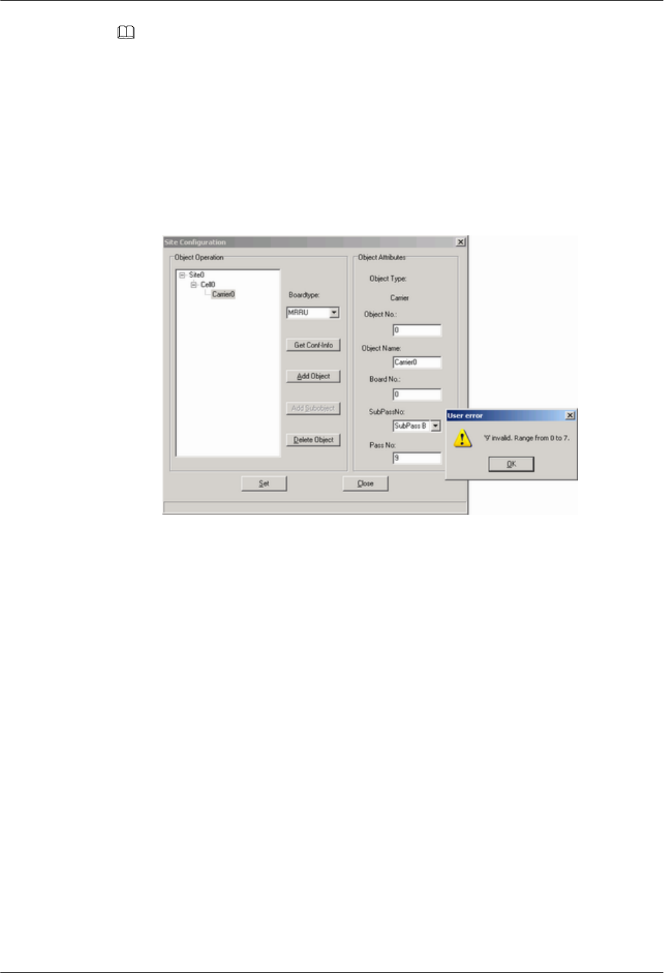
NOTE
lThe procedure for adding carriers for other TRX boards is the same as adding carrier for the DRFU.
lThe GRFU can be configured with 6 carriers, that is, there are 6 pass numbers ranging from 0 to 5 for
the same board number. The GRRU can be configured with 8 carriers, that is, there are 8 numbers
ranging from 0 to 7 for the same board number.
lThe GRRU has two tributaries: tributary A and tributary B. For other TRXs, there is only one tributary.
Therefore, you can configure the carrier according to the configuration data.
lThe SMT provides the self-check function. When an invalid value is specified, the User Error dialog
box is displayed, as shown in Figure 5-17.
Figure 5-17 User Error dialog box
Step 6 Click Site0.
The Set button is available. Click Set, Configuring cell succeeded is available, as shown in
Figure 5-18.
BTS3900(A) GSM
Commissioning Guide 5 Commissioning the BTS (Transmission Unavailable)
Issue 02 (2009-04-20) Huawei Proprietary and Confidential
Copyright © Huawei Technologies Co., Ltd.
5-17
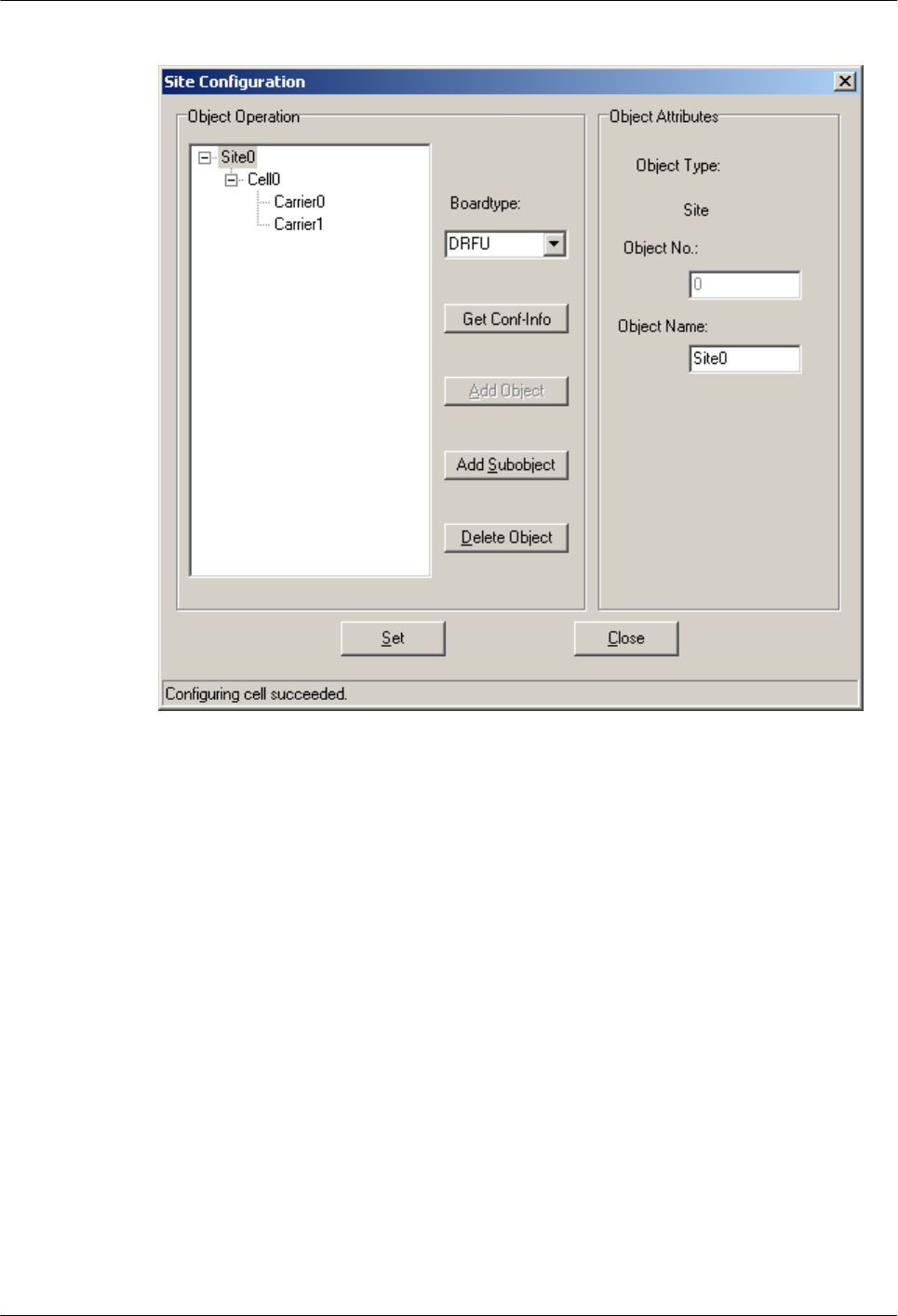
Figure 5-18 Site Configuration dialog box (6)
Step 7 Close the dialog box.
The configured cell is displayed in the navigation pane, as shown in Figure 5-19. The data is
configured but not activated. To activate the data, go to Step 8.
5 Commissioning the BTS (Transmission Unavailable)
BTS3900(A) GSM
Commissioning Guide
5-18 Huawei Proprietary and Confidential
Copyright © Huawei Technologies Co., Ltd.
Issue 02 (2009-04-20)
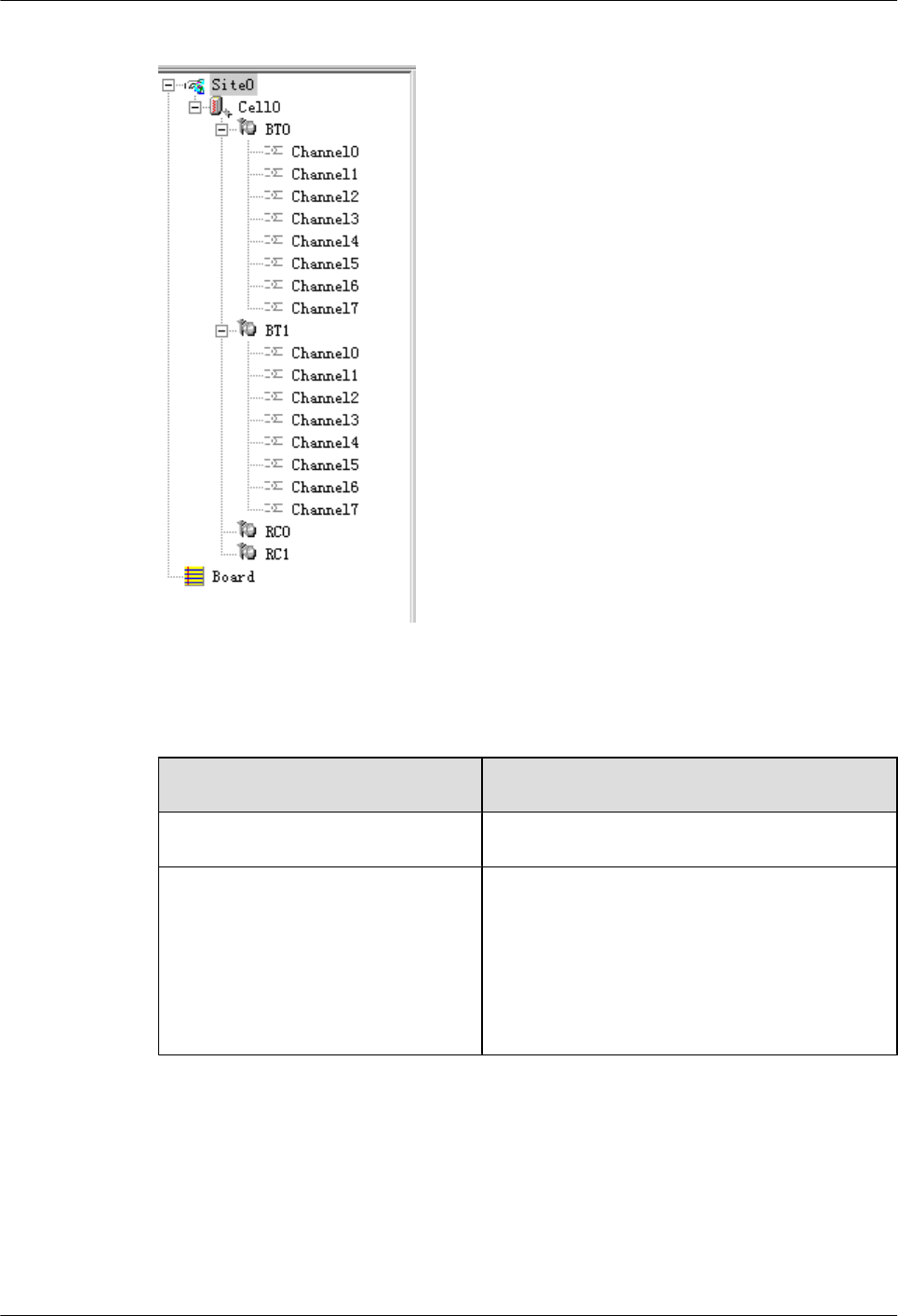
Figure 5-19 Configured cell and channels
Step 8 Choose Site0 > Site Opstart > OK. The Site Opstart dialog box is displayed, as shown in
Figure 5-20.
If... Then...
Site Opstart successfully. is displayed Click close to perform the next step.
Site startup fails 1. Repeat Step 8. If the operation succeeds, go to
Step 9. If the operation still fails, go to 8.2.
2. Check whether there is any inconsistent data
configuration. If there is, modify the inconsistent
data configuration. If the data configuration is
correct, contact the BTS technical support
engineers for troubleshooting.
BTS3900(A) GSM
Commissioning Guide 5 Commissioning the BTS (Transmission Unavailable)
Issue 02 (2009-04-20) Huawei Proprietary and Confidential
Copyright © Huawei Technologies Co., Ltd.
5-19
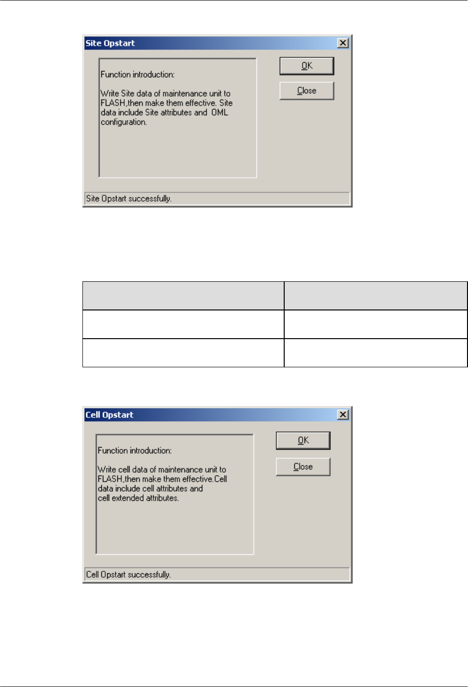
Figure 5-20 Site Opstart dialog box
Step 9 Choose Cell0 > Cell Opstart > OK. The Cell Opstart dialog box is displayed, as shown in
Figure 5-21.
If... Then...
Cell Opstart successfully. is displayed Click close to perform the next step.
Cell startup fails See Step 8 for further operation.
Figure 5-21 Cell Opstart dialog box
Step 10 The site configuration takes effect.
Step 11 Make the attributes of other TRXs take effect: Choose BT0 > BT Opstart > OK. The BT
Opstart dialog box is displayed, as shown in Figure 5-22.
5 Commissioning the BTS (Transmission Unavailable)
BTS3900(A) GSM
Commissioning Guide
5-20 Huawei Proprietary and Confidential
Copyright © Huawei Technologies Co., Ltd.
Issue 02 (2009-04-20)
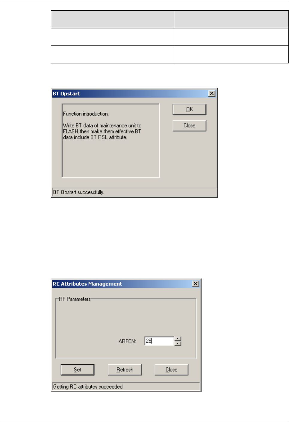
If... Then...
BT Opstart successfully. is displayed Click close to perform the next step.
BT startup fails See Step 8 for further operation.
Figure 5-22 BT Opstart dialog box
Step 12 Choose RC0 > RC Attributes Management. Specify frequency in ARFCN, and click Set.
Getting RC attributes succeeded is displayed. Click Close.
Repeat the procedure of Step 12 to set the frequencies of other TRXs. Figure 5-23 shows the
RC Attributes Management dialog box.
Figure 5-23 RC Attributes Management dialog box
BTS3900(A) GSM
Commissioning Guide 5 Commissioning the BTS (Transmission Unavailable)
Issue 02 (2009-04-20) Huawei Proprietary and Confidential
Copyright © Huawei Technologies Co., Ltd.
5-21
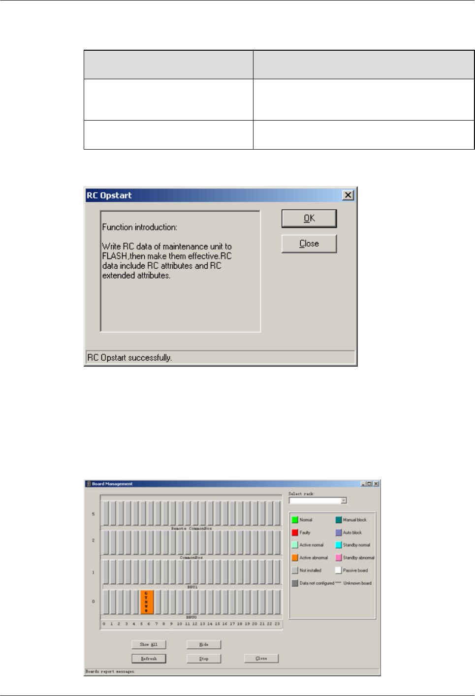
Step 13 Choose RC0 > RC Opstart > OK. The RC Opstart dialog box is displayed, as shown in Figure
5-24.
If... Then...
RC Opstart successfully. is displayed Click Close. Repeat Step 13 to make the frequency
settings of other RCs take effect.
RC startup fails See Step 8 for further operation.
Figure 5-24 RC Opstart successfully dialog box
Step 14 SFP Port Inconsistency Alarm is cleared. Since the transmission is unavailable, LAPD
Alarm persists, and the status of the GTMU is Active abnormal,
as shown in Figure 5-25.
Figure 5-25 Board Management window
5 Commissioning the BTS (Transmission Unavailable)
BTS3900(A) GSM
Commissioning Guide
5-22 Huawei Proprietary and Confidential
Copyright © Huawei Technologies Co., Ltd.
Issue 02 (2009-04-20)
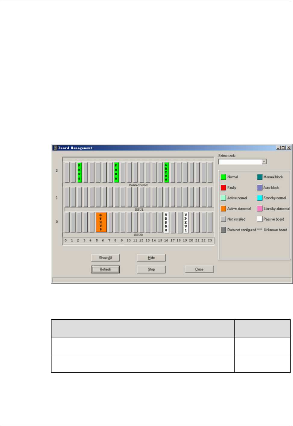
----End
5.3 Checking the Active Software Version on the SMT
This describes how to check the software versions of the boards and modules in the BTS in the
Site Maintenance Terminal System window.
Procedure
Step 1 In the left pane of the Site Maintenance Terminal System window, select Board. In the right
pane of the window, double-click Board Management.
The Board Management window is displayed, as shown in Figure 5-26.
Figure 5-26 Board Management window (1)
Step 2 Select a board or a module to be checked.
If... Then...
The DRFU is to be viewed Go to Step 3.
The GTMU, GATM, or PMU is to be viewed Go to Step 4.
Step 3 Double-click GTMU in the Board Management window. The Topology Management
window is displayed, as shown in Figure 5-27. Right-click DRFU0, and then click Board
Information. The query is successful. The Board Information dialog box is displayed, as
shown in Figure 5-28. Check the software version. If the version needs to be upgraded, reload
and activate the version, and then close the dialog box.
BTS3900(A) GSM
Commissioning Guide 5 Commissioning the BTS (Transmission Unavailable)
Issue 02 (2009-04-20) Huawei Proprietary and Confidential
Copyright © Huawei Technologies Co., Ltd.
5-23
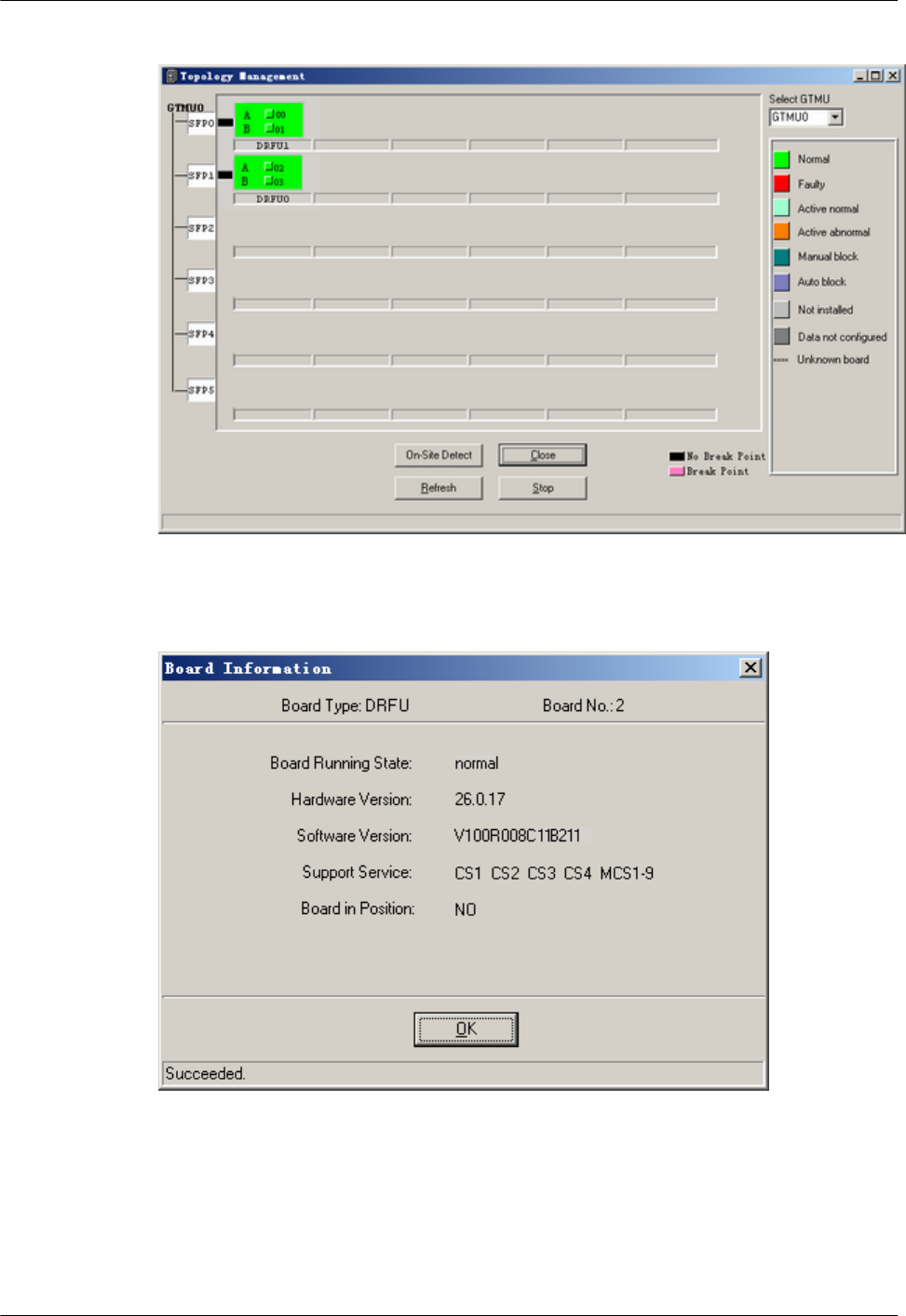
Figure 5-27 Topology Management window
Figure 5-28 Board Information dialog box (1)
Step 4 Take the GTMU as an example. Right-click GTMU, and choose Board Information from the
shortcut menu.
The Board Information dialog box is displayed, as shown in Figure 5-29. Check the software
version. If the software version is not correct, upgrade the software version. For details, see the
Software Upgrade Guide.
5 Commissioning the BTS (Transmission Unavailable)
BTS3900(A) GSM
Commissioning Guide
5-24 Huawei Proprietary and Confidential
Copyright © Huawei Technologies Co., Ltd.
Issue 02 (2009-04-20)
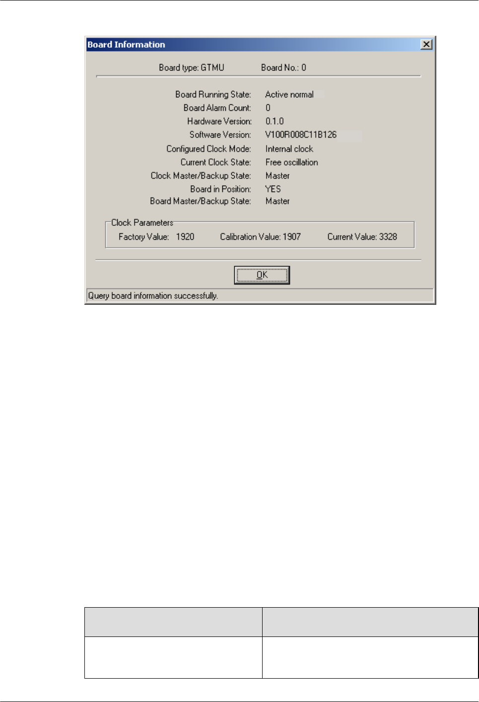
Figure 5-29 Board Information dialog box (2)
----End
5.4 Checking the Transmission Between the BBU and RFU
on the BTS Side
This describes how to check the transmission between the BBU and the RFU on the BTS side.
By checking the link status of the BBU and RFU, you can rectify the fault caused by abnormal
connection, thus ensuring normal communication between the BBU and the RFU.
Context
In this document, RFUs are classified into two types: DRFUs and GRFUs.
Procedure
Step 1 Check the status of the CPRI0 LED on the GTMU panel of the BBU and the status of the
CPRI0 and CPRI1 LEDs in the RFU panel.
If... Then...
All the LEDs are in the on in green
status
The communication between the CPRI0 port on
the BBU and the RFU is normal. Go to Step 4.
BTS3900(A) GSM
Commissioning Guide 5 Commissioning the BTS (Transmission Unavailable)
Issue 02 (2009-04-20) Huawei Proprietary and Confidential
Copyright © Huawei Technologies Co., Ltd.
5-25

If... Then...
Some LEDs are not in the on in green
status
The communication between the CPRI0 port on
the BBU and the RFU is faulty. Go to Step 2.
NOTE
The status of the LED corresponding to the CPRI port that is not in use should be OFF.
Step 2 Check the connection between the RFU and the BBU.
1. Check that one end of the CPRI signal cable is securely connected to the CPRI0 port on
the RFU, and the other end is securely connected to the CPRI port on the BBU.
2. Check the SFP male connectors at both ends of the CPRI signal cable. If the connector is
faulty, replace it.
3. If the LEDs is still in the on in green status, replace the optical module of the CPRI port.
Step 3 Check the connection between the cascaded RFUs.
1. Check that the signal cables between cascaded RFUs are securely connected to the
CPRI0 and CPRI1 ports.
2. Check the SFP male connectors at both ends of the signal cables between cascaded RFUs.
If the connector is faulty, replace it.
3. If the LEDs is still in the on in green status, replace the optical module connected to the
CPRI port.
Step 4 Repeat Step 1 through Step 3 to check the transmission between other CPRI ports on the GTMU
panel and other RFUs.
----End
5.5 Checking the Running Status of the BTS
This describes how to check the running status of the BTS. Check the running status of the BTS
involves checking the status of LEDs and alarm information on the SMT.
5.5.1 Checking the State of the BTS LEDs
To determine the running status of the BTS boards or modules, you need to check the state of
the LEDs on them. The LEDs are distributed on the following boards or modules: GTMU
(mandatory), UBFA, UPEU, RFU, GATM (optional), FAN unit, PMU, PSU (AC/DC), and PSU
(DC/DC).
5.5.2 Checking the Alarm Information of the BTS on the SMT
This describes how to check the BTS alarms on the SMT. If an alarm is generated, you need to
clear the alarm according to the handling suggestions on the SMT.
5.5.1 Checking the State of the BTS LEDs
To determine the running status of the BTS boards or modules, you need to check the state of
the LEDs on them. The LEDs are distributed on the following boards or modules: GTMU
(mandatory), UBFA, UPEU, RFU, GATM (optional), FAN unit, PMU, PSU (AC/DC), and PSU
(DC/DC).
5 Commissioning the BTS (Transmission Unavailable)
BTS3900(A) GSM
Commissioning Guide
5-26 Huawei Proprietary and Confidential
Copyright © Huawei Technologies Co., Ltd.
Issue 02 (2009-04-20)
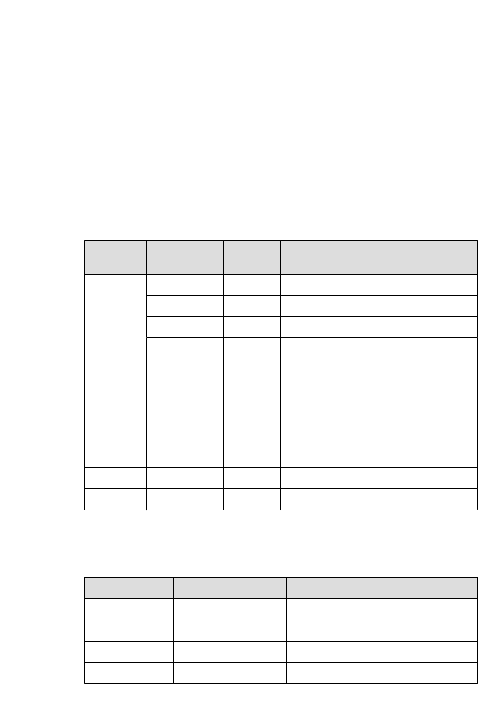
Prerequisite
The output power of the TRX is within the normal range, and the RFU operates properly.
Context
lThe PSU (AC/DC) that converts 220 V AC power into -48 V DC power is used when the
external 220 V AC power input is used.
lThe PSU (DC/DC) that converts +24 V AC power into -48 V DC power is used when the
external +24 V AC power input is used.
Procedure
Step 1 Check the state of the LEDs on the boards or modules in the BBU. Table 5-2 lists the normal
states of the LEDs on the boards or modules.
Table 5-2 Normal states of the LEDs on the board and modules in the BBU
Board or
Module
LED Color Normal State
GTMU RUN Green Blinking (ON for 1s and OFF for 1s)
ALM Red OFF
ACT Green ON
LIU0 to LIU3 Green LEDs LIU0 to LIU3 represent the four E1
links. If the links are connected normally, LIU
LEDs are OFF. If the links are not connected
to the BSC yet or the transmission is
unavailable, LIU LEDs are ON.
CPRI0 to
CPRI5
Green When CPRI0 to CPRI5 ports are not in use,
the LEDs are OFF. When the BBU is
normally connected to the RFU, the
corresponding LED is ON.
UBFA STATE Green Blinking (ON for 1s and OFF for 1s)
UPEU RUN Green ON
Step 2 Check the state of the LEDs on the RFU panel. Table 5-3 takes the DRFU as an example to list
the normal states of the LEDs on the RFU panel.
Table 5-3 Normal states of the LEDs on the DRFU
LED Color Normal State
RUN - Blinking (ON for 1s and OFF for 1s)
ALM - OFF
ACT - ON steady: The DRFU works properly.
VSWR Red OFF
BTS3900(A) GSM
Commissioning Guide 5 Commissioning the BTS (Transmission Unavailable)
Issue 02 (2009-04-20) Huawei Proprietary and Confidential
Copyright © Huawei Technologies Co., Ltd.
5-27
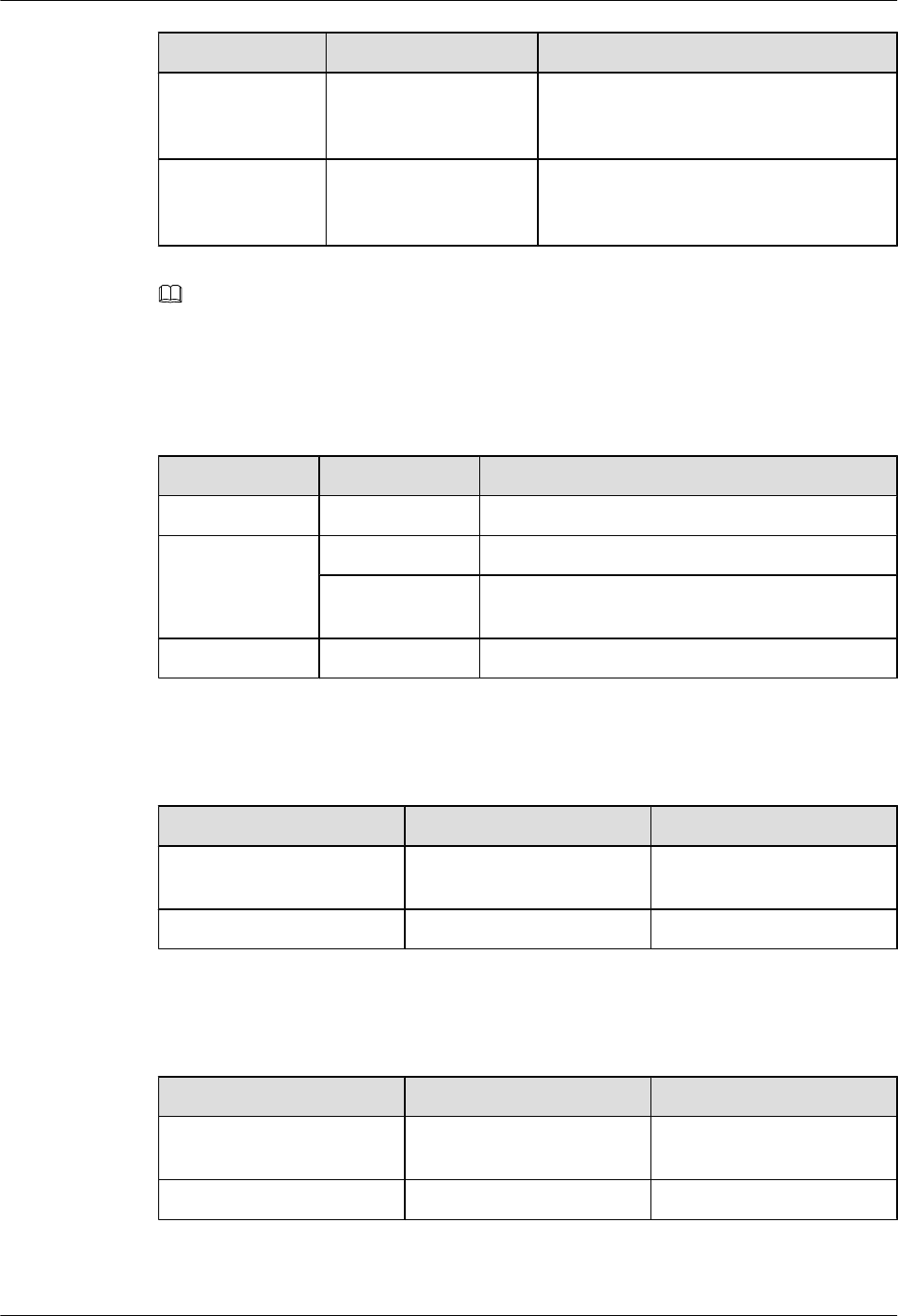
LED Color Normal State
CPRI0 Green If the DRFU is normally connected to the
BBU or another RFU, the LED is ON. If the
DRFU is not connected, the LED is OFF.
CPRI1 Green If the DRFU is normally connected to the
BBU or another RFU, the LED is ON. If the
DRFU is not connected, the LED is OFF.
NOTE
The LEDs on other RFUs have the same states as those on the DRFU, but the silkscreens of some LEDs
are different.
Step 3 Check the status of the LEDs on the GATM panel. Table 5-4 lists the normal status of the LEDs.
Table 5-4 Normal states of the LEDs on the GATM
LED Color Normal State
RUN Green Blinking (ON for 1s and OFF for 1s)
ACT Green ON: The AISG link is available.
Green Blinking quickly: The AISG link is in transmission
status.
ALM Red OFF
Step 4 Check the states of the LEDs on the FAN unit panel. Table 5-5 lists the normal states of the
LEDs.
Table 5-5 Normal states of the LEDs on the FAN unit
LED Color Normal State
RUN Green Blinking (ON for 1s and OFF
for 1s)
ALM Red OFF
Step 5 Check the state of the LEDs on the PMU panel. Table 5-6 lists the normal states of the LEDs
on the PMU.
Table 5-6 Normal states of the LEDs on the PMU
LED Color Normal State
RUN Green Blinking (ON for 1s and OFF
for 1s)
ALM Red OFF
Step 6 Check the state of the LEDs on the PSU (AC/DC) or PSU (DC/DC) panel. Table 5-7 lists the
normal states of the LEDs on the PSU.
5 Commissioning the BTS (Transmission Unavailable)
BTS3900(A) GSM
Commissioning Guide
5-28 Huawei Proprietary and Confidential
Copyright © Huawei Technologies Co., Ltd.
Issue 02 (2009-04-20)

Table 5-7 Normal states of the LEDs on the PSU
PSU LED Color Normal State
PSU (AC/DC) Power input LED
(top)
Green ON
Power protection
LED (middle)
Yellow OFF
Power failure LED
(bottom)
Red OFF
PSU (DC/DC) Power input LED
(left)
Green ON
Power protection
LED (middle)
Yellow OFF
Power failure LED
(right)
Red OFF
Step 7 If the LEDs on the boards or modules are not in the normal state, check the alarm information
on the SMT and rectify the faults according to the suggestions displayed.
----End
5.5.2 Checking the Alarm Information of the BTS on the SMT
This describes how to check the BTS alarms on the SMT. If an alarm is generated, you need to
clear the alarm according to the handling suggestions on the SMT.
Procedure
Step 1 In the left pane of the Site Maintenance Terminal System window, choose Board. In the right
pane of the window, double-click Board Management.
The Board Management window is displayed, as shown in Figure 5-30.
BTS3900(A) GSM
Commissioning Guide 5 Commissioning the BTS (Transmission Unavailable)
Issue 02 (2009-04-20) Huawei Proprietary and Confidential
Copyright © Huawei Technologies Co., Ltd.
5-29
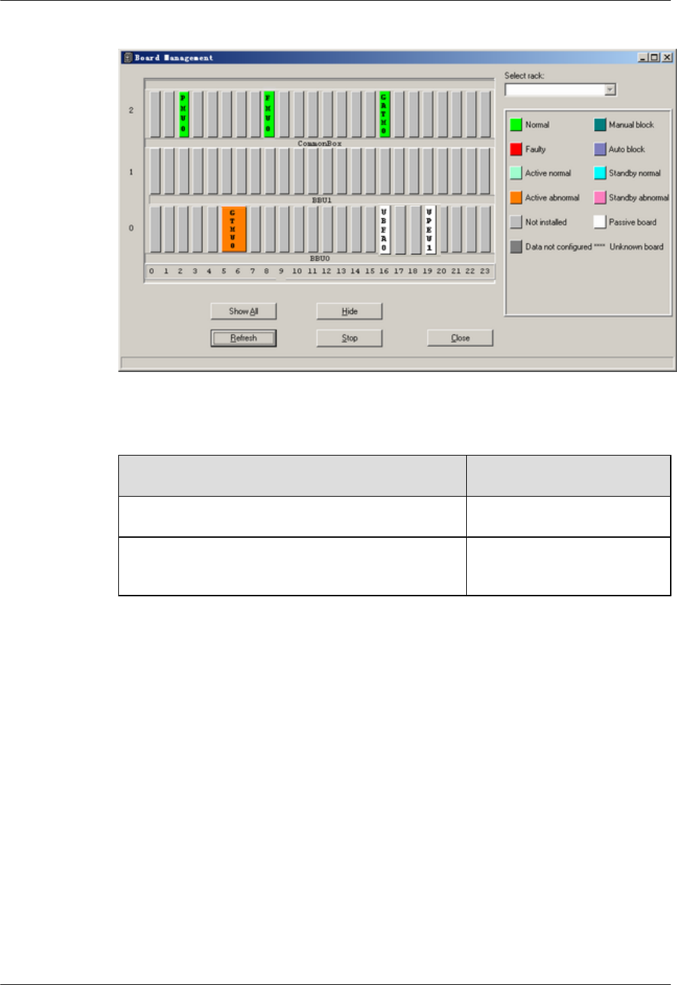
Figure 5-30 Board Management window
Step 2 Check the type of the board or module where alarms are generated.
If... Then...
The board or module is RFU Go to Step 3 to query the alarms.
The board or module is GTMU, UBFA, UPEU, UEIU,
GATM, or PMU
Go to Step 4 to query the alarms.
Step 3 In the Board Management window, double-click GTMU.
The Topology Management window is displayed, as shown in Figure 5-31.
5 Commissioning the BTS (Transmission Unavailable)
BTS3900(A) GSM
Commissioning Guide
5-30 Huawei Proprietary and Confidential
Copyright © Huawei Technologies Co., Ltd.
Issue 02 (2009-04-20)
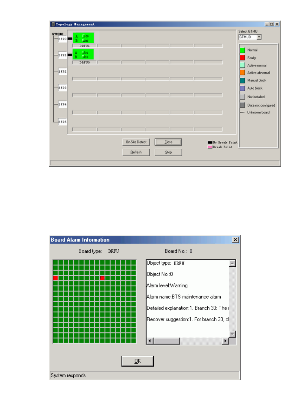
Figure 5-31 Topology Management window
Step 4 Right-click the board or module to be queried, and choose Board Alarm.
The Board Alarm Information dialog box is displayed. Click the red grid, then the details about
the alarm are displayed in the right pane, as shown in Figure 5-32.
Figure 5-32 Board Alarm Information dialog box
BTS3900(A) GSM
Commissioning Guide 5 Commissioning the BTS (Transmission Unavailable)
Issue 02 (2009-04-20) Huawei Proprietary and Confidential
Copyright © Huawei Technologies Co., Ltd.
5-31
NOTE
Each red grid represents an alarm.
Step 5 Perform the next operation according to the result displayed in the Board Alarm
Information dialog box.
If... Then...
No alarm is generated Close the Board Alarm Information dialog box.
Repeat steps Step 2 through Step 5 and query
alarms generated in other boards or modules.
An alarm is generated Clear the alarm based on the troubleshooting
suggestions.
NOTE
When the transmission is unavailable, which indicates that the BTS is not connected to the BSC, certain
alarms are generated in common cases. These alarms are theE1 Local Alarm of the GTMU, the SW Not
Activated Alarm, the LAPD Alarm, and the SFP Port Inconsistency Alarm. The SFP Port
Inconsistency Alarm is reported only when the TRX is connected but not configured or is configured but
not connected.
----End
5.6 Checking the Hardware Connection of the BTS
This describes how to check the hardware connection of the BTS by checking the connection
of power cables, grounding cables, and all kinds of signal cables.
Procedure
Step 1 For checking the connection of power cables and grounding cables, see Table 5-8.
Table 5-8 Checklist for the connection of the power cables and grounding cables
SN Check Item
1The unused connectors of the power cables are capped.
2 The PGND cable is green and yellow. The DC grounding cable is black.
The -48 V DC power cable is blue. The cross-sectional area of the PGND
cable is 16 mm2.
3 All the power cables and grounding cables are copper-core cables. The
outer diameter of the external power cables and grounding cables is about
11 mm.
4 The power cables and grounding cables are not short-circuited or
reversely connected.
5 The power cables and grounding cables are bound separately from other
cables.
5 Commissioning the BTS (Transmission Unavailable)
BTS3900(A) GSM
Commissioning Guide
5-32 Huawei Proprietary and Confidential
Copyright © Huawei Technologies Co., Ltd.
Issue 02 (2009-04-20)
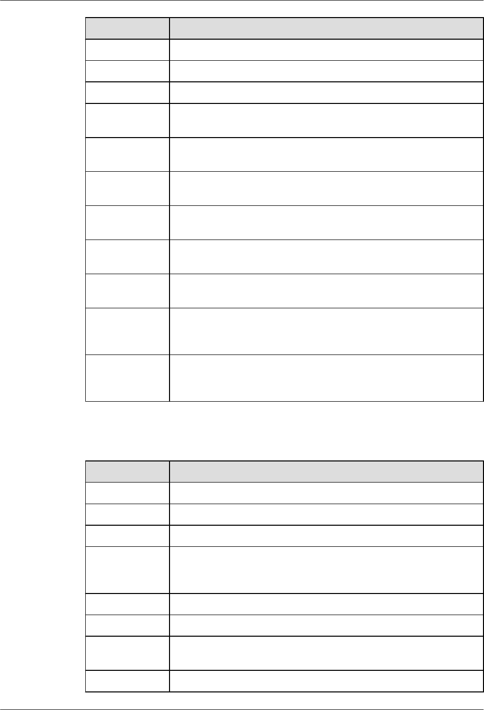
SN Check Item
6Labels are attached to both ends of the power cables and grounding cables.
7 The power cables and grounding cables are not damaged or broken.
8 There are no connectors or joints on the power cables or grounding cables.
9 There are no breaking equipment, such as switches and fuses, in the
electrical connection of the grounding system.
10 The redundant part of the power cables or grounding cables is stripped
off rather than coiled.
11 The lugs on both ends of the power cables or grounding cables are
soldered or crimped securely.
12 Bare wires and lug handles at the wiring terminals are tightly wrapped
with insulating tapes or heat-shrinkable tubes.
13 The flat washers and spring washers are well mounted on all wiring
terminals.
14 The diameter of the positive pole of the primary power supply connected
to the earth complies with the standard requirements.
15 The working grounding and protection grounding of the BTS and the
surge protection grounding of the building share one group of grounding
conductors.
16 The grounding grids of the tower, equipment room, and distribution
transformer (if the distance between the transformer and the equipment
room is less than 30 m) constitute an integrated grounding grid.
Step 2 See Table 5-9 to check the connection of all the signal cables.
Table 5-9 Checklist for the connection of the signal cables
SN Check Item
1The connectors of the E1 cables are tight and secure.
2 The connectors of the E1 cables are intact.
3 The E1 cables or RF cables are not damaged or broken.
4 The connectors of the RF cables are fixed in position to prevent the
possible false connection from causing abnormal voltage standing wave
ratio (VSWR).
5 The horizontal RF cables are clamped to the cable trough.
6 The proper cable surpluses are reserved at the connectors.
7 All cables are neatly bound with ties installed at even intervals, to a proper
tightness, and in the same direction.
8 Extra cable ties are cut off. All cuts are smooth without sharp projections.
BTS3900(A) GSM
Commissioning Guide 5 Commissioning the BTS (Transmission Unavailable)
Issue 02 (2009-04-20) Huawei Proprietary and Confidential
Copyright © Huawei Technologies Co., Ltd.
5-33

SN Check Item
9The cable layout facilitates maintenance and future capacity expansion.
10 All the labels and tags at both ends of the cables are legible.
11 The unused ports are covered with dust-proof covers and matching plugs.
12 The indoor 1/2-inch jumpers are distributed according to the layer and
sector.
13 The indoor 1/2-inch jumpers are kept straight for 300 mm at their joints
with the cabinet.
----End
5 Commissioning the BTS (Transmission Unavailable)
BTS3900(A) GSM
Commissioning Guide
5-34 Huawei Proprietary and Confidential
Copyright © Huawei Technologies Co., Ltd.
Issue 02 (2009-04-20)

6 Optional Commissioning Tasks
About This Chapter
The optional commissioning tasks are the VSWR check, output power of the TRX check,
loopback test check, settings of the DIP switches on the board check, transmission between the
BBU and the BSC on the BTS side check, transmission between cascaded TRXs check, and
TRX ring topology check.
6.1 Commissioning the Antenna System
This describes how to commission the antenna system. You must check whether the VSWR is
normal, whether the output power of the TRX is normal, and whether the antenna is connected
properly. If an RET antenna is configured, you need to commission it.
6.2 Performing the Loopback Test
This describes how to perform the loopback test. The loopback test is optional. Before testing
CS and PS services, you must check the transmission links of the signaling channels and traffic
channels in the BTS. Loopback tests can be classified into the carrier loopback test and the
channel loopback test.
6.3 Checking the DIP Switch Settings of the Boards
This describes how to check whether the settings of the DIP switches on the board are correct.
You can perform this task by checking whether the attribute values corresponding to the DIP
switches meet the actual requirements on the LMT.
6.4 Locally Checking the Transmission Between the BBU and the BSC
This describes how to check the status of the LEDs on the GTMU panel, how to check the
connections of the E1 cable and E1 surge protection transfer cable. It also describes how to clear
the fault caused by improper connections to ensure that the BBU communicates properly with
the BSC.
6.5 Checking the Transmission Between Cascaded TRXs
This describes how to check the transmission between cascaded TRXs. The following
description is based on three levels of cascaded TRXs.
6.6 Checking TRXs in Ring Topology
This describes how to check TRXs in ring topology on site. The following description is based
on level 3 of TRXs in ring topology.
BTS3900(A) GSM
Commissioning Guide 6 Optional Commissioning Tasks
Issue 02 (2009-04-20) Huawei Proprietary and Confidential
Copyright © Huawei Technologies Co., Ltd.
6-1

6.1 Commissioning the Antenna System
This describes how to commission the antenna system. You must check whether the VSWR is
normal, whether the output power of the TRX is normal, and whether the antenna is connected
properly. If an RET antenna is configured, you need to commission it.
6.1.1 Measuring the VSWR
This describes how to measure whether the VSWR is less than or equal to 1.5. If the VSWR is
less than or equal to 1.5, the transmission of the antenna system is normal. To measure the
VSWR, perform the following steps where the Site Master is taken as an example.
6.1.2 Monitoring the Output Power of TRXs
This describes how to obtain the output power of the TRX, which indicates the running status
of the TRXs.
6.1.3 Checking the Antenna Connection
This describes how to check the antenna connections with an MS. You can lock the MS on a
cell frequency and perform the dialing test. If the MS dialing test is successful, the antenna is
properly connected.
6.1.1 Measuring the VSWR
This describes how to measure whether the VSWR is less than or equal to 1.5. If the VSWR is
less than or equal to 1.5, the transmission of the antenna system is normal. To measure the
VSWR, perform the following steps where the Site Master is taken as an example.
Prerequisite
The BTS is powered off.
NOTE
If you have checked the VSWR before powering on the BTS, you do not need to perform this task.
Procedure
Step 1 Measure the VSWR at the antenna port by using the Site Master.
If... Then...
The VSWR is less than or equal to 1.5 The transmission of the antenna system is
operational. Record the VSWR in the
Commissioning Record Data Sheet.
If the VSWR is greater than 1.5 The transmission of the antenna system is faulty. Go
to Step 2.
Step 2 Use the Site Master to locate the fault point of the abnormal VSWR on the jumper or feeder.
When a fault point is found, check whether the connections are secure at the fault point, and
whether the connectors are intact. If the connector is faulty, replace it.
6 Optional Commissioning Tasks
BTS3900(A) GSM
Commissioning Guide
6-2 Huawei Proprietary and Confidential
Copyright © Huawei Technologies Co., Ltd.
Issue 02 (2009-04-20)
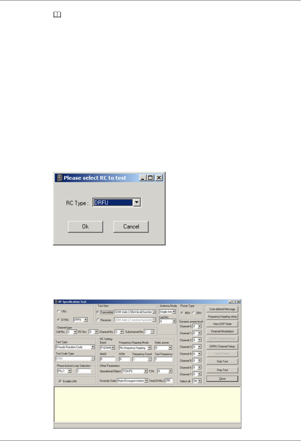
NOTE
The fault points are usually at the connection point between the jumper and the feeder or between the
jumper and the antenna.
----End
6.1.2 Monitoring the Output Power of TRXs
This describes how to obtain the output power of the TRX, which indicates the running status
of the TRXs.
Procedure
Step 1 Connect the power meter to the ANT port on the RFU.
Step 2 In the navigation bar of the Site Maintenance Terminal System window, choose Site. In the
browse window, double-click RF Specification Test. The Please select RC to test dialog box
is displayed. Select the board to be tested, as shown in Figure 6-1.
Figure 6-1 Please select RC to test dialog box
Step 3 Click OK. The RF Specification Test dialog box is displayed, as shown in Figure 6-2.
Figure 6-2 RF Performance Test dialog box
BTS3900(A) GSM
Commissioning Guide 6 Optional Commissioning Tasks
Issue 02 (2009-04-20) Huawei Proprietary and Confidential
Copyright © Huawei Technologies Co., Ltd.
6-3
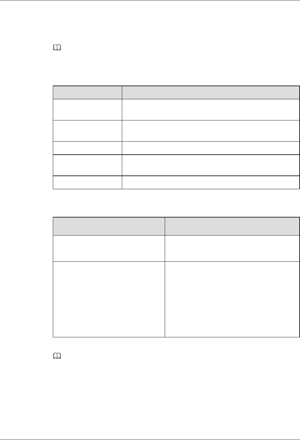
Step 4 Set the parameters listed in Table 6-1. Then, click User-defined Message. Then, click Start
Test to initiate the test on the output power of the TRXs.
NOTE
The parameters not involved in Table 6-1 can use the default values.
Table 6-1 Parameter required in RF performance test
Group Box Type Parameter Setting Description
Testing Items Select Transmitter, and retain the default settings of the drop-
down list.
Antenna Mode Set the corresponding antenna mode and Card No. based on the
actual configuration.
Power Type Set Power Type according to the actual configuration.
Channel Type Select Cell No., RC No., and Channel No. based on the actual
configuration.
AC Setting Select Band based on actual configuration. Set Static power to 0.
Step 5 Check the output power displayed in the power meter. Determine whether the output power of
the TRX is within the normal range.
If... Then...
The output power is within the normal
range
Record the power in the 8 Commissioning Record
Data Sheet.
The output power is beyond the normal
range
1. Check whether the connection between the
power meter and the cable is secure.
2. Check whether the power meter is correctly set.
If any fault exists, clear it.
3. Check whether the RFU is correctly configured
and can transmit power.
4. Replace the RFU in which the TRX does not
transmit power normally.
NOTE
lThe output power displayed in the power meter is the power of the BTS with power sharing disabled.
The permissible offset of the power is ±1 dBm.
lThe TX output power displayed on the power meter is only that of a single carrier, rather than the total
power of all the carriers in the RFU module.
Step 6 Repeat steps Step 2 through Step 5 to check the output power of all the carriers at the site.
----End
6 Optional Commissioning Tasks
BTS3900(A) GSM
Commissioning Guide
6-4 Huawei Proprietary and Confidential
Copyright © Huawei Technologies Co., Ltd.
Issue 02 (2009-04-20)

6.1.3 Checking the Antenna Connection
This describes how to check the antenna connections with an MS. You can lock the MS on a
cell frequency and perform the dialing test. If the MS dialing test is successful, the antenna is
properly connected.
Prerequisite
lThe BTS is powered on and works normally.
lThe transmission between the BSC and the BTS is normal.
lThe antenna system is connected to the cabinet.
lThe test MS is registered in the HLR.
Procedure
Step 1 Power on one test MS, and check that the MS automatically searches for the GSM network.
If... Then...
The test MS fails to find the GSM
network
lCheck whether the test MS has a SIM card. If
the test MS does not have a SIM card, insert the
SIM card in the MS.
lCheck whether the SIM card supports
authentication and encryption. If the SIM card
does not support authentication or encryption,
replace it.
lCheck whether the test MS is functional. If the
test MS is faulty, replace it.
The test MS finds the GSM network Go to Step 2.
Step 2 Lock the test MS on a frequency in a logical cell under the BTS.
Step 3 Perform the dialing test using the test MS. Then, check whether the antenna corresponding to
the frequency is connected properly according to the test results.
If... Then...
The dialing test is successful You can infer that the feeder corresponding to the
frequency is connected properly. Go to Step 4.
The dialing test is not successful You can infer that the antenna system on the frequency
may be connected improperly. Check the antenna
connection and adjust the antenna.
BTS3900(A) GSM
Commissioning Guide 6 Optional Commissioning Tasks
Issue 02 (2009-04-20) Huawei Proprietary and Confidential
Copyright © Huawei Technologies Co., Ltd.
6-5

NOTE
You are advised to do as follows to ensure the accuracy of test results:
lMake test calls within the power range of -30 dBm to -70 dBm under the tower.
lPerform the dialing test for more than five times.
Step 4 Repeat steps Step 2 through Step 3 to check the antenna connections on all the frequencies of
the BTS.
----End
6.2 Performing the Loopback Test
This describes how to perform the loopback test. The loopback test is optional. Before testing
CS and PS services, you must check the transmission links of the signaling channels and traffic
channels in the BTS. Loopback tests can be classified into the carrier loopback test and the
channel loopback test.
Prerequisite
lThe transmission between the BSC and the BTS is normal.
lThe current software version and data configuration on the LMT are correct.
lNo alarm related to disruption of BTS services is reported.
6.2.1 Performing the Carrier Loopback Test
This describes how to perform the carrier loopback test. Before testing CS and PS services, you
must check the transmission links of the signaling channels in the BTS.
6.2.2 Performing Channel Loopback Tests
This describes how to perform channel loopback tests. Before testing CS and PS services, you
must check that the transmission links of the traffic channels in the BTS are proper.
6.2.1 Performing the Carrier Loopback Test
This describes how to perform the carrier loopback test. Before testing CS and PS services, you
must check the transmission links of the signaling channels in the BTS.
Context
The BIU loopback test is performed to test the link transmission of the TRX timeslots on the
BTS DBUS.
Procedure
Step 1 On the BSC6000 Local Maintenance Terminal window, choose BTS Maintenance >
Maintain TRX > Test TRX Loopback.
The Test TRX Loopback dialog box is displayed, as shown in Figure 6-3.
6 Optional Commissioning Tasks
BTS3900(A) GSM
Commissioning Guide
6-6 Huawei Proprietary and Confidential
Copyright © Huawei Technologies Co., Ltd.
Issue 02 (2009-04-20)
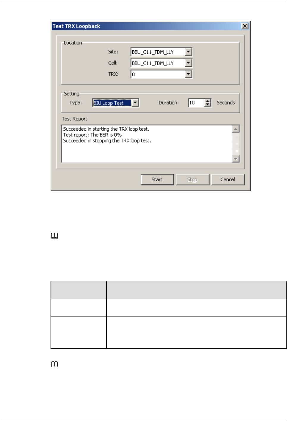
Figure 6-3 Test TRX Loopback dialog box
Step 2 Set the parameters in the Location and Setting areas. That is, set Type to BIU Loop Test, and
set Site, Cell, and TRX as required.
NOTE
The maximum Duration of the BIU loop test is the default value, which is 10s. In most cases, the default
value is used.
Step 3 Click Start to perform the test. The result is displayed in the Test Result area, as shown in
Figure 6-3.
If... Then...
The BER is 0% The signaling channel is normal.
The BER is not 0% The signaling channel is abnormal. Record the number of the faulty
TRX, and contact Huawei BTS technical support engineers for
troubleshooting.
NOTE
During the test, you can click Stop to stop the test. The Succeeded in stopping the TRX loop test. message
is displayed in the Test Result area.
Step 4 Repeat steps Step 1 through Step 3 to perform the loopback test on the other TRXs.
----End
BTS3900(A) GSM
Commissioning Guide 6 Optional Commissioning Tasks
Issue 02 (2009-04-20) Huawei Proprietary and Confidential
Copyright © Huawei Technologies Co., Ltd.
6-7
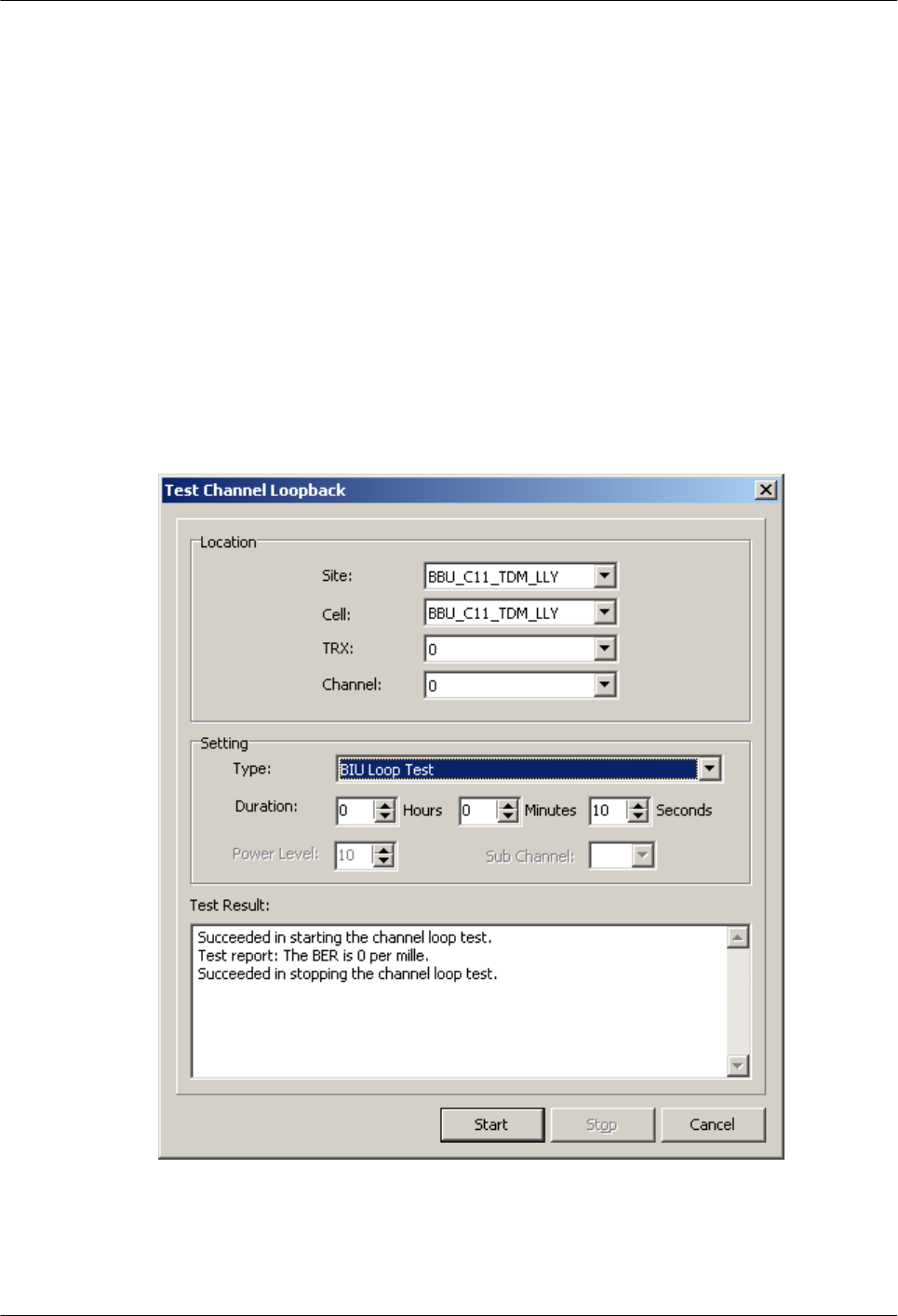
6.2.2 Performing Channel Loopback Tests
This describes how to perform channel loopback tests. Before testing CS and PS services, you
must check that the transmission links of the traffic channels in the BTS are proper.
Context
The BIU loopback test is performed to test the timeslot transmission over the TRX traffic channel
on the DBUS in the BTS.
Procedure
Step 1 On the BSC6000 Local Maintenance Terminal window, choose BTS Maintenance >
Maintain TRX > Test Channel Loopback.
The Test Channel Loopback dialog box is displayed, as shown in Figure 6-4.
Figure 6-4 Test Channel Loopback dialog box
Step 2 Set the parameters in the Location and Setting areas. That is, set Type to BIU Loop Test, and
set Site, Cell, TRX and Channelas required.
6 Optional Commissioning Tasks
BTS3900(A) GSM
Commissioning Guide
6-8 Huawei Proprietary and Confidential
Copyright © Huawei Technologies Co., Ltd.
Issue 02 (2009-04-20)

NOTE
The maximum Duration of the BIU loop test is the default value, which is 10s. In most cases, the default
value is used.
Step 3 Click Start. The Confirm dialog box is displayed. Click Yes to perform the test. The result is
displayed in the Test Result area, as shown in Figure 6-4.
If... Then...
The BER is 0 per mille The service channel is normal.
The BER is not 0 per mille The service channel is abnormal. Record the number of the
faulty TRX, and contact Huawei BTS technical support
engineers for troubleshooting.
NOTE
During the test, you can click Stop to stop the test. The Succeeded in stopping the TRX loop test. message
is displayed in the Test Result area.
Step 4 Repeat steps Step 1 through Step 3 to perform the loopback test on the other channels.
----End
6.3 Checking the DIP Switch Settings of the Boards
This describes how to check whether the settings of the DIP switches on the board are correct.
You can perform this task by checking whether the attribute values corresponding to the DIP
switches meet the actual requirements on the LMT.
Prerequisite
lThe BTS is in TDM transmission mode.
lThe transmission between the BSC and the BTS is normal.
Procedure
Step 1 Query the information of the GTMU: In the BSC6000 Local Maintenance Terminal window,
select the target site. Right-click GTMU on the Site Device Panel tab page, and choose Query
Board Information. The Query Board Information dialog box is displayed.
Step 2 Click the Running Parameter tab, and then click Query on the Running Parameter tab page.
The query is successful, and the running status of the board is displayed in the dialog box.
Step 3 Check whether Attribute Value of E1/T1 Capability and Impedance Capability consistent
with the actual condition, as shown in Figure 6-5.
lIf the attribute values are consistent with the actual condition, end the task.
lIf the attribute values are not consistent with the actual condition, see the BTS3900 Quick
Installation Guide or the BTS3900A Quick Installation Guide to set the corresponding DIP
switches on the BTS side again.
BTS3900(A) GSM
Commissioning Guide 6 Optional Commissioning Tasks
Issue 02 (2009-04-20) Huawei Proprietary and Confidential
Copyright © Huawei Technologies Co., Ltd.
6-9
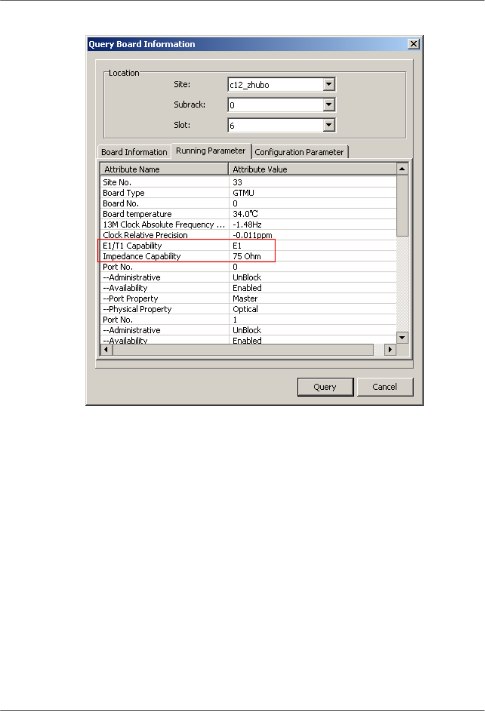
Figure 6-5 Site Device Attributes dialog box
----End
6.4 Locally Checking the Transmission Between the BBU
and the BSC
This describes how to check the status of the LEDs on the GTMU panel, how to check the
connections of the E1 cable and E1 surge protection transfer cable. It also describes how to clear
the fault caused by improper connections to ensure that the BBU communicates properly with
the BSC.
Prerequisite
lThe BBU is connected to the BSC through an E1/T1 cable.
lThe BBU and the BSC are successfully powered on.
6 Optional Commissioning Tasks
BTS3900(A) GSM
Commissioning Guide
6-10 Huawei Proprietary and Confidential
Copyright © Huawei Technologies Co., Ltd.
Issue 02 (2009-04-20)
Procedure
Step 1 Check whether the settings of DIP switch meet the field requirements. if not, modify the settings
of DIP switch as required.
Step 2 Check the status of the LEDs LIU0 to LIU3 on the panel of the GTMU in the BBU. The LEDs
LIU0 to LIU3 correspond to link 1 to 4 of the E1/T1 cable. Each link has one TX line and one
RX line.
If... Then...
The LEDs are OFF The E1/T1 links are normal. End this task.
The LEDs are ON or ON for 0.125s and OFF
for 0.125s
The E1/T1 links are abnormal. Go to Step 3.
NOTE
You need check the status of only the LIU LEDs corresponding to the E1/T1 line in use. The LIU LEDs
corresponding to the unused E1/T1 cables are ON.
lIf the BBU is in non cascaded, there is only one E1/T1 link between the BBU and the BSC and the
corresponding LED is LIU0. If the LIU0 LED is OFF, it indicates the communication between the
BBU and the BSC is normal. Otherwise, the communication is abnormal.
lIf the two BBUs are cascaded, the second E1/T1 link of level 1 BBU is connected to the first E1/T1
link of level 2 BBU. Check the LIU1 LED and LIU0 LED on level 1 BBU and level 2 BBU respectively
to verify whether the physical link is operational. If multiple BBUs are cascaded, check the LEDs of
the corresponding links.
lIf the BBU and the BSC form a ring, check the LIUs corresponding to the links in the ring to verify
whether the communication is normal. For the connections of multiple BBUs and the LEDs to be
checked, see that of the two BBUs in cascading connection.
Step 3 Check the connections and connectors at both ends of the cables. If the connector is damaged,
replace it.
If... Then...
The UELP is configured lCheck whether the E1/T1 cable is connected properly
to the OUTSIDE port on the UELP.
lCheck whether the E1 surge protection transfer cable
is connected properly to the INSIDE port on the
UELP.
lCheck whether the E1 surge protection transfer cable
is connected properly to the E1/T1 on the GTMU.
The UELP is not configured Check whether the E1/T1 cable is connected properly
to the E1/T1 port on the GTMU.
Step 4 At the DDF on the BTS side, check the soldering conditions for the connectors of the E1/T1 link
where the communication is abnormal. Ensure sound jointing, since poor jointing may cause
poor E1/T1 connection.
Step 5 Perform a physical loopback test on the E1/T1 cable where the communication is abnormal.
Check whether the transmission of the E1/T1 cable is normal on the BTS side.
BTS3900(A) GSM
Commissioning Guide 6 Optional Commissioning Tasks
Issue 02 (2009-04-20) Huawei Proprietary and Confidential
Copyright © Huawei Technologies Co., Ltd.
6-11
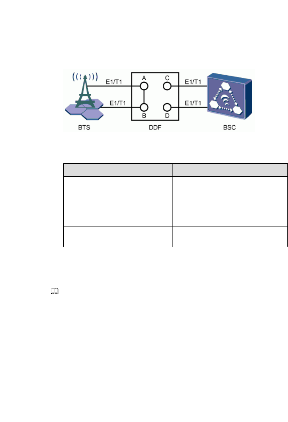
1. For a pair of E1s/T1s connecting the BTS and BSC through the DDF, the A port is connected
to the C port, and the B port is connected to the D port. In the loopback test, disconnect the
A port from the C port, and the B port from the D port, and then connect the A port to the
B port, as shown in Figure 6-6. In this way, the TX end and RX end of the E1/T1 line is
connected and the physical loopback is formed on the BTS side.
Figure 6-6 Physical loopback of E1/T1 at the DDF
2. Check the status of the LIU LEDs on the GTMU panel again.
If... Then...
The LEDs are OFF The E1/T1 connections are normal on the
BTS side. The problem may be that the
connection between the BTS and the BSC or
the connections on the BSC side are faulty.
End the check, and contact the BSC
technical support engineer to clear the fault.
The LEDs are ON or ON for 0.125s and
OFF for 0.125s
The cable connections on the BTS side are
faulty. Clear the fault on the BTS side.
3. Set the E1s/T1s at the DDF on the BTS side from physical loopback to normal connection.
Ensure that the connections are sound.
Step 6 Check the E1/T1 connections at the DDF. Ensure that the TX and RX ends of the E1 cables are
connected properly.
NOTE
Do as follows to distinguish the E1 RX end from the E1 TX end:
Connect a pin of an LED to the wire of the E1/T1 cable, and the other pin to the shielding layer of the E1/
T1 cable. If the LED is ON, this end is the TX end. If the LED is OFF, this end is the RX end.
----End
6.5 Checking the Transmission Between Cascaded TRXs
This describes how to check the transmission between cascaded TRXs. The following
description is based on three levels of cascaded TRXs.
Prerequisite
The physical connection between cascaded TRXs on the BTS side is complete.
6 Optional Commissioning Tasks
BTS3900(A) GSM
Commissioning Guide
6-12 Huawei Proprietary and Confidential
Copyright © Huawei Technologies Co., Ltd.
Issue 02 (2009-04-20)
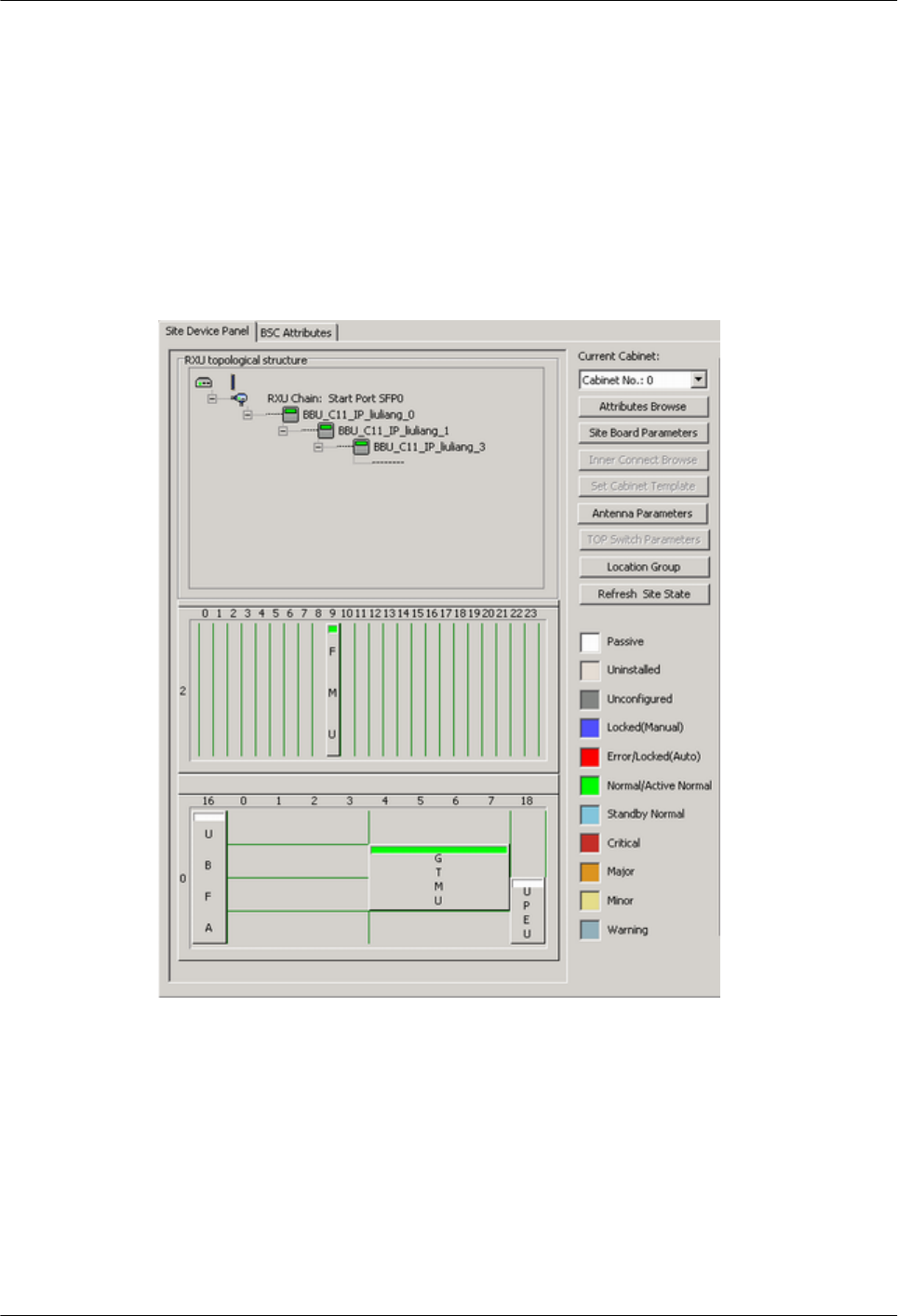
Procedure
Step 1 In the navigation tree in the left pane of the BSC6000 Local Maintenance Terminal window,
select the BTS, and check whether the status of the three cascaded TRXs on the Site Device
Panel tab page is green, as shown in Figure 6-7.
lIf the TRXs are displayed in green, you can infer that the TRXs are functional. End this
task.
lIf the TRXs are displayed in other colors, you can infer that the transmission between
cascaded TRXs is abnormal. Go to Step 2.
Figure 6-7 Site Device Panel tab page
Step 2 If the status of the level 2 TRX and level 3 TRX is red, you can infer that the link between the
level 1 TRX and level 2 TRX is faulty. The system reports SFP Port Inconsistency Alarm.
Check whether the connection between the TRXs on the BTS side is normal, or clear the alarm
based on the BSS Alarm Reference.
Step 3 If the status of the level 3 TRX is red, you can infer that the link between the level 2 TRX and
level 3 TRX is faulty. The system reports SFP Port Inconsistency Alarm. Check the
BTS3900(A) GSM
Commissioning Guide 6 Optional Commissioning Tasks
Issue 02 (2009-04-20) Huawei Proprietary and Confidential
Copyright © Huawei Technologies Co., Ltd.
6-13
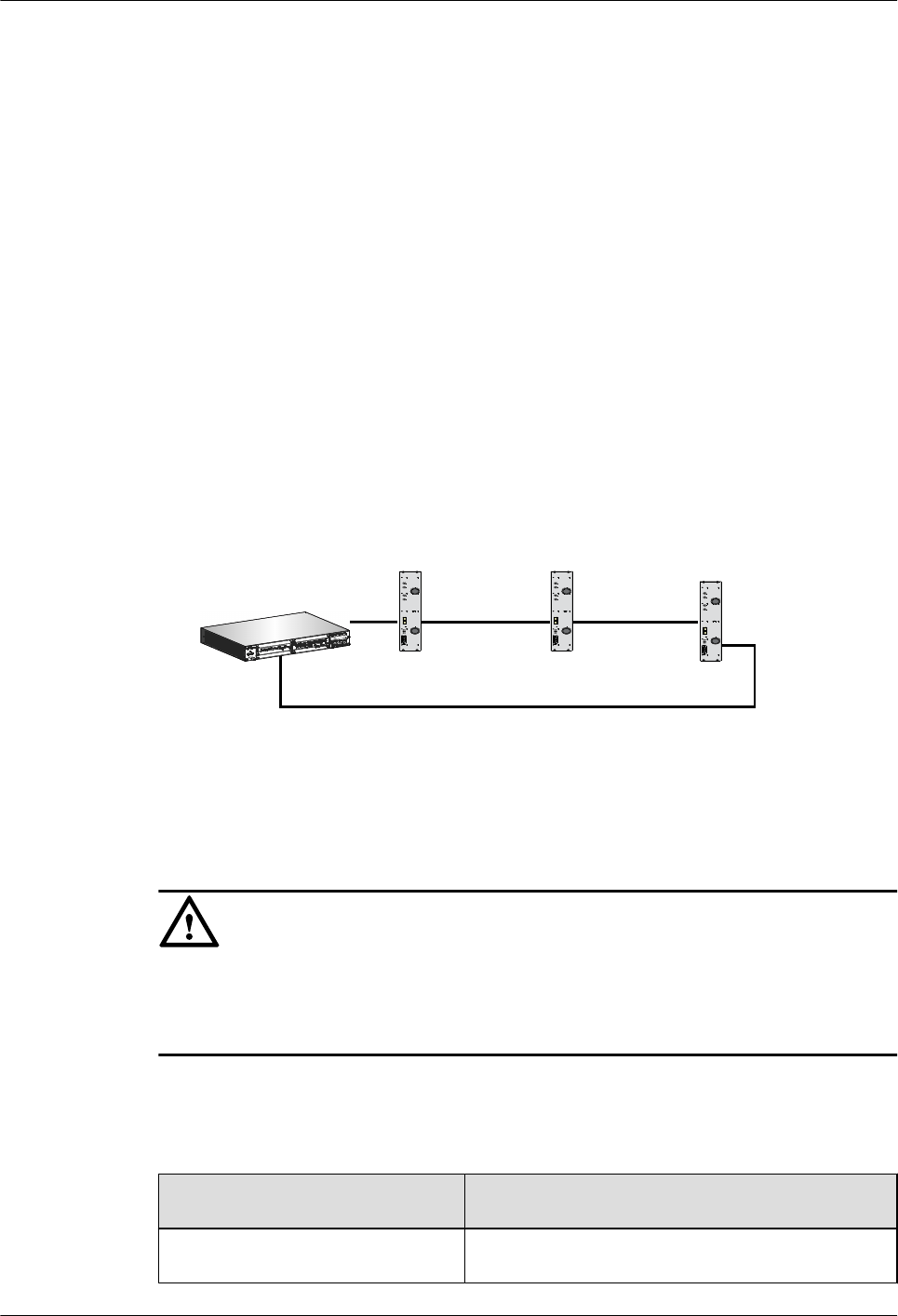
transmission between the TRXs on the BTS side, or clear the alarm based on the BSS Alarm
Reference.
----End
6.6 Checking TRXs in Ring Topology
This describes how to check TRXs in ring topology on site. The following description is based
on level 3 of TRXs in ring topology.
Prerequisite
lThe physical connection between TRXs in ring topology on the BTS side is complete.
lThe configuration of the TRXs in ring topology on the BSC side is complete.
Context
lFigure 6-8 shows the connection between TRXs in ring topology. A, B, C, and D indicate
the positions where the link may be broken during the ring topology transmission.
Figure 6-8 Connection between TRXs in ring topology
BBU
RFU0 RFU1 RFU2
A B C
D
D R F U
Rx 1 in
Rx 1 o u t AN T 1
AN T 2
PW R
CP R I_ 0
CP R I_ 1
RST
RUN ALM
VSW RACT
CPR L 0 CPR L 1
Rx 2 in
Rx 2 o u t
D R F U
Rx 1 in
Rx 1 o u t AN T 1
AN T 2
PW R
CP R I_ 0
CP R I_ 1
RST
RUN ALM
VSW RACT
CPR L 0 CPR L 1
Rx 2 in
Rx 2 o u t
D R F U
Rx 1 in
Rx 1 o u t AN T 1
AN T 2
PW R
CP R I_ 0
CP R I_ 1
RST
RUN ALM
VSW RACT
CPR L 0 CPR L 1
Rx 2 in
Rx 2 o u t
lThe GTMU reports SFP Port Inconsistency Alarm when the ring topology is used in
physical connection but not in data configuration, or when the ring topology is used in data
configuration but not in physical connection.
CAUTION
Do not set breakpoints on the LMT when the TRXs are cascaded through the SFP high-speed
signal cable. Otherwise, the board will be seriously damaged. You can directly connect and
disconnect the signal cable between the cascaded TRXs to check the connection between them.
Procedure
Step 1 Check whether the TRX ring topology is configured on the LMT.
If... Then...
The ring topology is configured Go to Step 2.
6 Optional Commissioning Tasks
BTS3900(A) GSM
Commissioning Guide
6-14 Huawei Proprietary and Confidential
Copyright © Huawei Technologies Co., Ltd.
Issue 02 (2009-04-20)
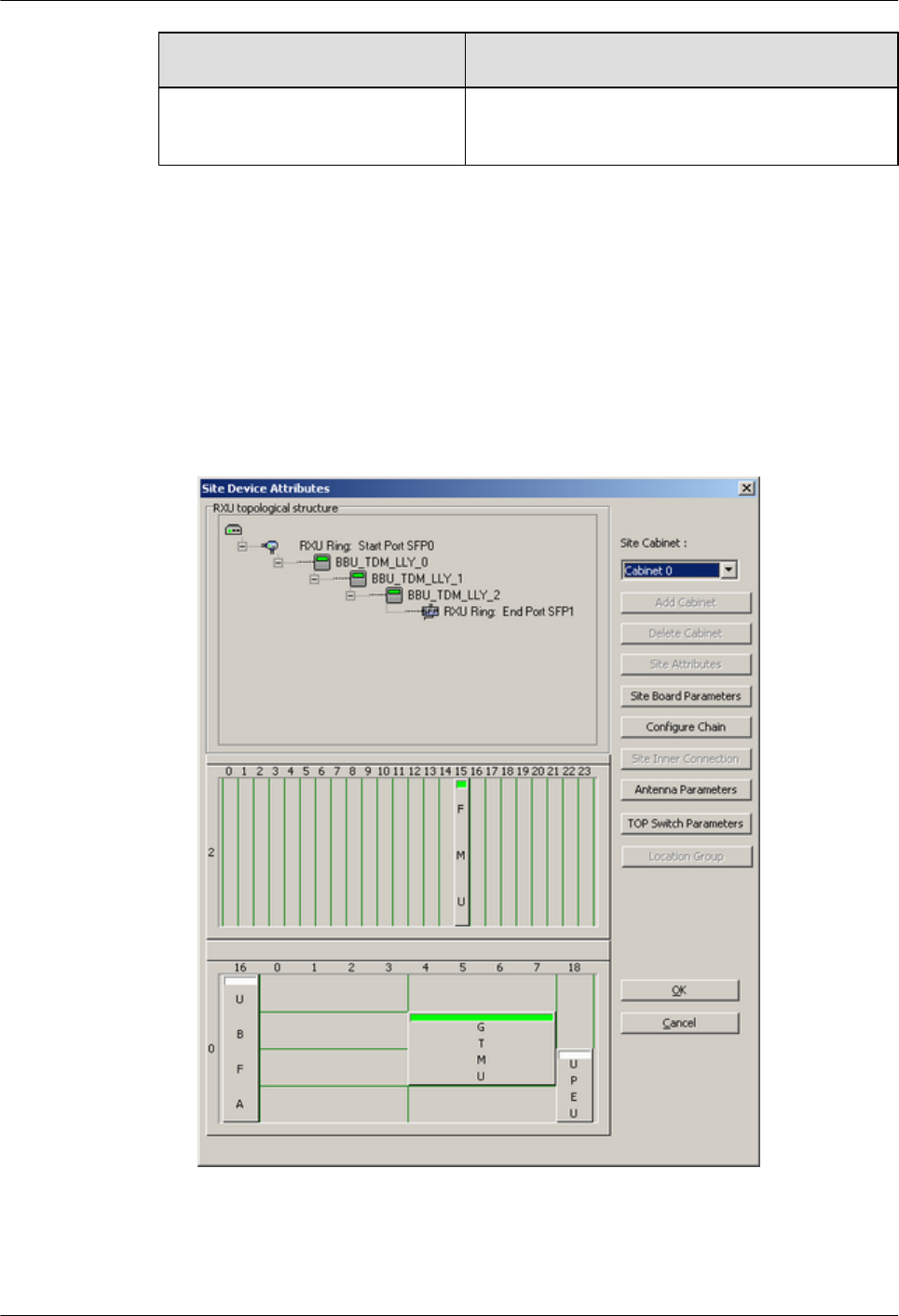
If... Then...
The ring topology is not configured Configure the ring topology. For details, see the BSC
Initial Configuration Guide.
Step 2 Change the TRX ring topology test to TRX cascaded test. The purpose of setting breakpoints
on the LMT is to simulate the scenario that faults occur on the transmission link. In this way,
you can check whether the TRXs are automatically switched to chain topology and whether the
alarm is reported.
1. in the BSC6000 Local Maintenance Terminal window, right-click the target site, and
choose Configure Site Board Attributes. The Site Device Attributes dialog box is
displayed.
2. Click Configure Site Board Attributes. The Site Device Attributes dialog box is
displayed, as shown in Figure 6-9.
Figure 6-9 Site Device Attributes dialog box
3. Right-click the RXU chain, and choose Set Break Point. The Set RXU Chain Break
Point dialog box is displayed.
BTS3900(A) GSM
Commissioning Guide 6 Optional Commissioning Tasks
Issue 02 (2009-04-20) Huawei Proprietary and Confidential
Copyright © Huawei Technologies Co., Ltd.
6-15
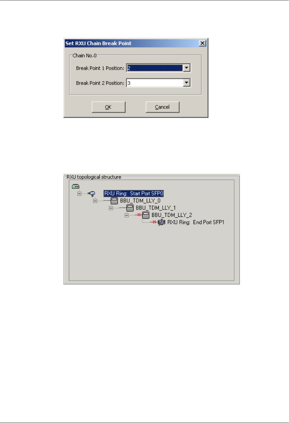
4. Set the breakpoint to disconnect the level 3 TRX, as shown in Figure 6-10.
Figure 6-10 Set RXU Chain Break Point dialog box
5. Click OK to return to the Site Device Attributes dialog box. The breakpoints marked with
red cross are displayed, as shown in Figure 6-11.
Figure 6-11 Setting breakpoint successfully
6. Click OK, and then click Finish to return to the BSC6000 Local Maintenance
Terminal window. The level 3 TRX is disconnected, and the Site Device Panel tab page
displays the faulty state, as shown in Figure 6-12.
6 Optional Commissioning Tasks
BTS3900(A) GSM
Commissioning Guide
6-16 Huawei Proprietary and Confidential
Copyright © Huawei Technologies Co., Ltd.
Issue 02 (2009-04-20)
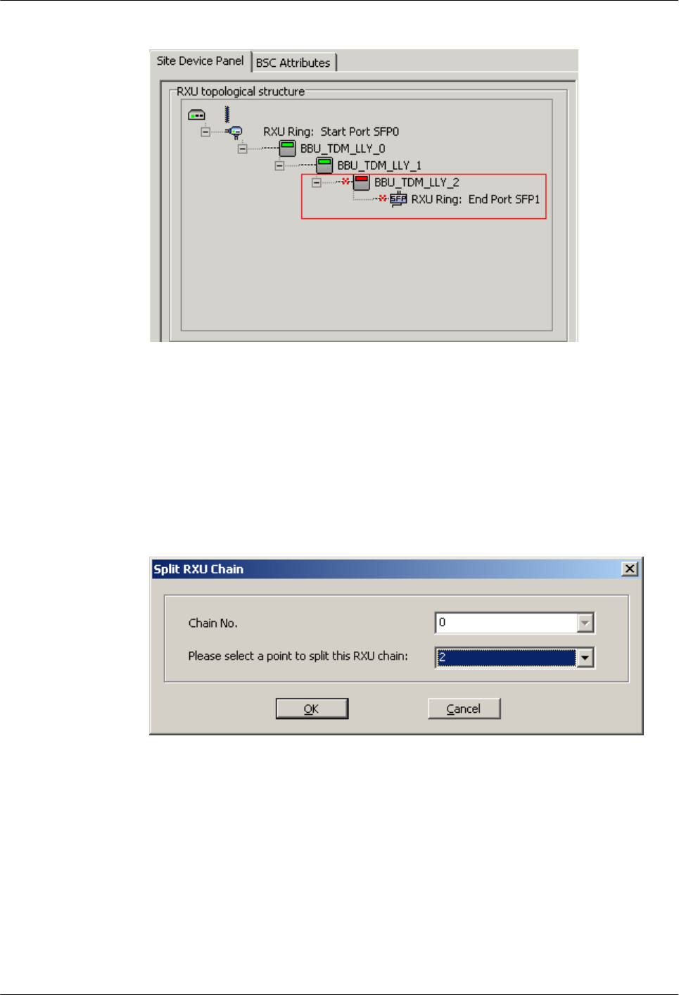
Figure 6-12 Status of the disconnected TRX ring topology
7. Right-click the site, and choose Configure Site Board Attributes from the shortcut menu.
The Configure Site Boards Attributes dialog box is displayed.
8. Click Configure Site Board Attributes, the Site Device Attributes dialog box is
displayed.
9. Right-click the RXU chain, and choose Combine or Separate RXU Chain. The Split
RXU Chain dialog box is displayed, as shown in Figure 6-13.
Figure 6-13 Split RXU Chain dialog box
10. Set Please select a point to split this RXU Chain to 2. Click OK, and then return to the
Site Device Attributes dialog box. The level 3 TRX is configured under the RXU link.
The start port is SFP1, as shown in Figure 6-14.
BTS3900(A) GSM
Commissioning Guide 6 Optional Commissioning Tasks
Issue 02 (2009-04-20) Huawei Proprietary and Confidential
Copyright © Huawei Technologies Co., Ltd.
6-17
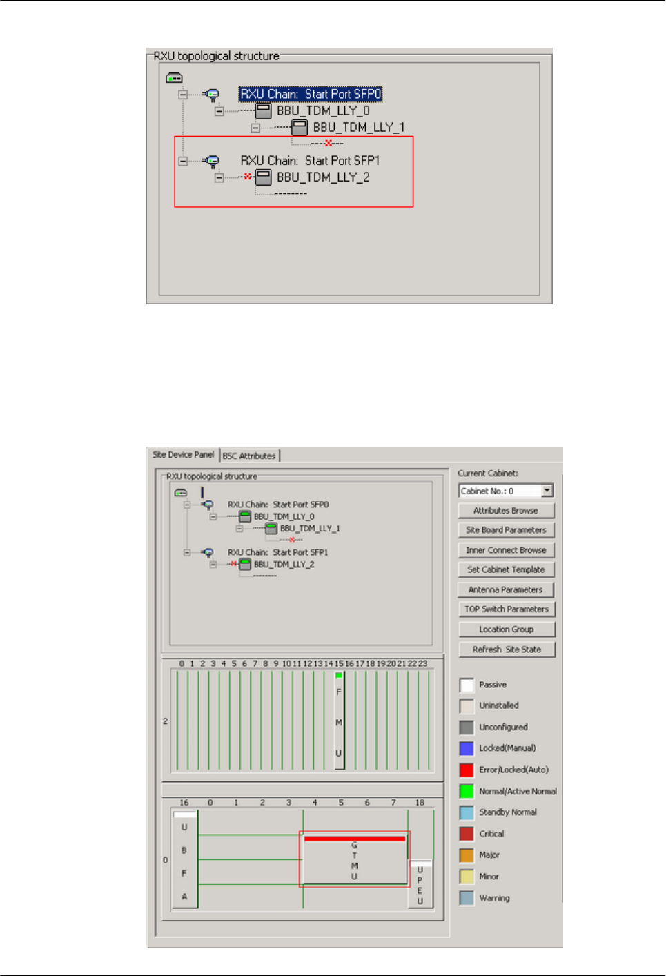
Figure 6-14 Splitting RXU chain successfully
11. Click OK, and then click Finish to return to the BSC6000 Local Maintenance
Terminal window. Figure 6-15 shows the data configuration on the Site Device Panel tab
page. The GTMU reports the SFP Port Inconsistency Alarm.
Figure 6-15 TRX ring topology in splitting state
6 Optional Commissioning Tasks
BTS3900(A) GSM
Commissioning Guide
6-18 Huawei Proprietary and Confidential
Copyright © Huawei Technologies Co., Ltd.
Issue 02 (2009-04-20)
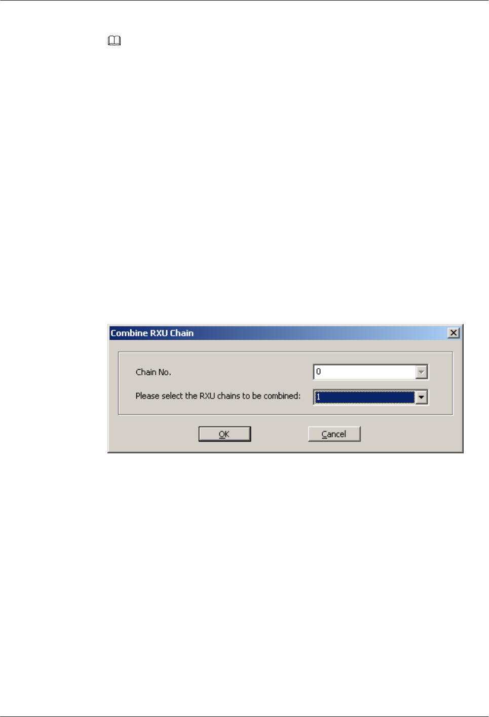
NOTE
After Step 2.11 is performed, the status of the RFU is Faulty, and the TRX Communication
Alarm is reported. Wait one to two minutes, and the TRX Communication Alarm is cleared, and
the state of the RFU is Normal.
Step 3 Change the TRX cascaded test to TRX ring topology test. The purpose of removing breakpoints
on the LMT is to simulate the scenario that the faults on the transmission link. In this way, you
can check whether the TRXs are automatically switched to ring topology and whether the alarm
is automatically cleared.
1. In the BSC6000 Local Maintenance Terminal window, right-click the target site and
choose Configure Site Board Attributes. The Site Device Attributes dialog box is
displayed.
2. Click Configure Site Board Attributes. The Site Device Attributes dialog box is
displayed.
3. Right-click the RXU chain, and choose Combine or Separate RXU Chain. The Combine
RXU Chain dialog box is displayed.
4. Set Chain No. and Please select the RXU chains to be combined, as shown in Figure
6-16. The following description takes combining RXU chain 1 to RXU chain 0 as an
example.
Figure 6-16 Combine RXU Chain dialog box
5. Click OK, and return to the Site Device Attributes dialog box. The RXU Chain becomes
RXU Ring, as shown in Figure 6-17.
BTS3900(A) GSM
Commissioning Guide 6 Optional Commissioning Tasks
Issue 02 (2009-04-20) Huawei Proprietary and Confidential
Copyright © Huawei Technologies Co., Ltd.
6-19
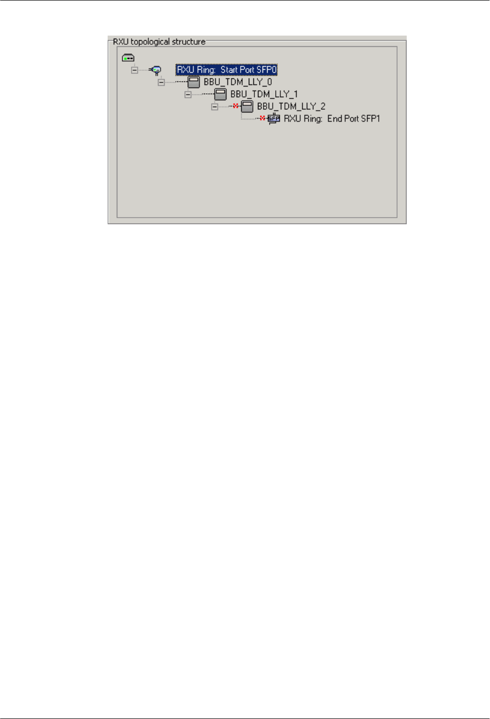
Figure 6-17 Combining RXU chain successfully
6. Click OK, and then click Finish to return to the BSC6000 Local Maintenance
Terminal window. Figure 6-18 shows the status of boards on the Site Device Panel tab
page. SFP Port Inconsistency Alarm is cleared. The level 3 TRX, however, is in the
disconnected state due to the breakpoint. Therefore, TRX Communication Alarm is
reported.
6 Optional Commissioning Tasks
BTS3900(A) GSM
Commissioning Guide
6-20 Huawei Proprietary and Confidential
Copyright © Huawei Technologies Co., Ltd.
Issue 02 (2009-04-20)
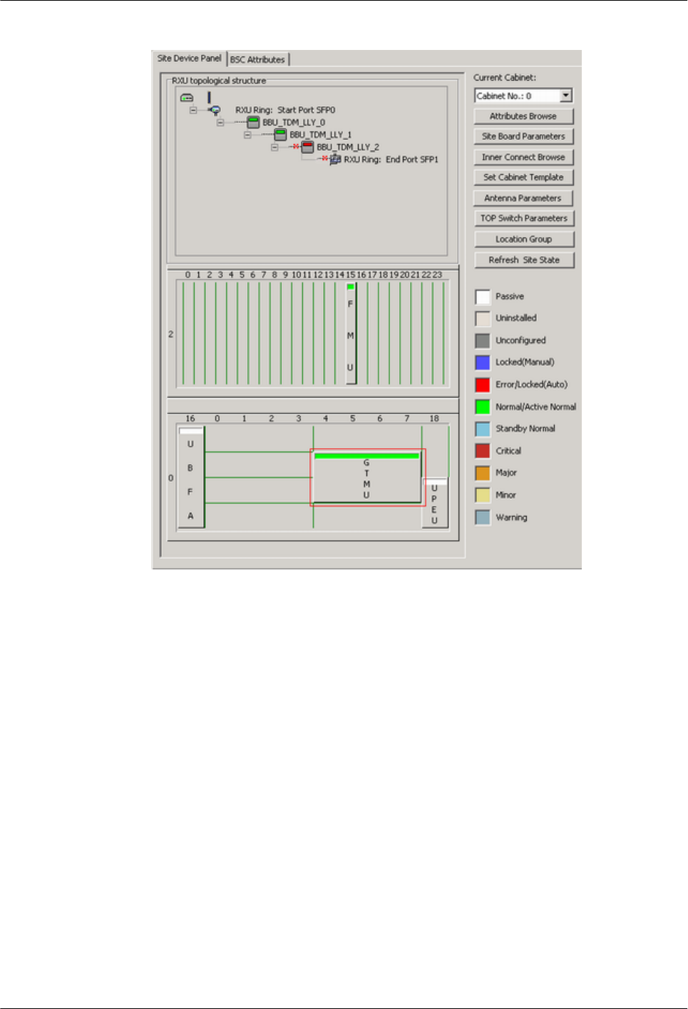
Figure 6-18 RXU ring in combined state
7. In the BSC6000 Local Maintenance Terminal window, right-click the target site and
choose Configure Site Board Attributes, and the Site Device Attributes dialog box is
displayed.
8. Click Configure Site Board Attributes. The Site Device Attributes dialog box is
displayed.
9. Right-click the RXU chain, and choose Set Break Point. The Set RXU Chain Break
Point dialog box is displayed.
10. Delete breakpoints: Set Break Point 1 Position and Break Point 2 Position to NULL.
11. Click OK, and return to the Site Device Attributes dialog box. The two breakpoints marked
with red cross are cleared.
12. Click OK, and then click Finish to return to the BSC6000 Local Maintenance
Terminal window. All the alarms are cleared, and the status of each board is normal, as
shown in Figure 6-19.
BTS3900(A) GSM
Commissioning Guide 6 Optional Commissioning Tasks
Issue 02 (2009-04-20) Huawei Proprietary and Confidential
Copyright © Huawei Technologies Co., Ltd.
6-21
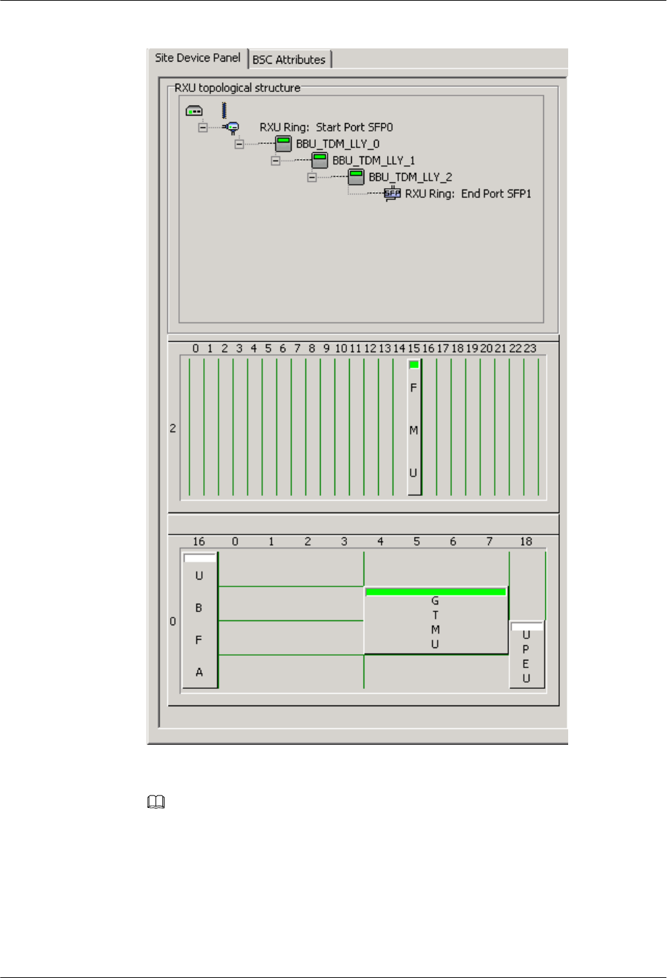
Figure 6-19 RXU Ring in normal state
NOTE
After Step 3.12 is performed, the status of the RFU is Faulty, and the TRX Communication
Alarm is reported. Wait one to two minutes, and the TRX Communication Alarm will be cleared,
and the status of the RFU is Normal.
----End
6 Optional Commissioning Tasks
BTS3900(A) GSM
Commissioning Guide
6-22 Huawei Proprietary and Confidential
Copyright © Huawei Technologies Co., Ltd.
Issue 02 (2009-04-20)

7 FAQs for BTS Commissioning
About This Chapter
This describes the fault symptoms and cause analysis in the BTS commissioning.
7.1 Failed Communication Between the SMT and the BTS
This describes the symptom of the communication failure between the SMT and the BTS and
analyzes the cause of the failed communication. It also provides the fault handling suggestions.
7.2 Faulty E1 Link
This describes the fault symptom and analyzes the cause of the faulty E1 link. It also provides
the fault handling suggestions.
7.3 Failure of an MS to Search the Network
This describes the fault symptom and analyzes the cause of the failure of an MS to search the
network.
7.4 Service Dialing Failure
This describes the fault symptom and analyzes the cause of the service dialing failure. It also
provides the fault handling suggestions.
7.5 Low GPRS Data Transmission Rate
This describes the fault symptom and analyzes the cause of low GPRS data transmission rate.
BTS3900(A) GSM
Commissioning Guide 7 FAQs for BTS Commissioning
Issue 02 (2009-04-20) Huawei Proprietary and Confidential
Copyright © Huawei Technologies Co., Ltd.
7-1
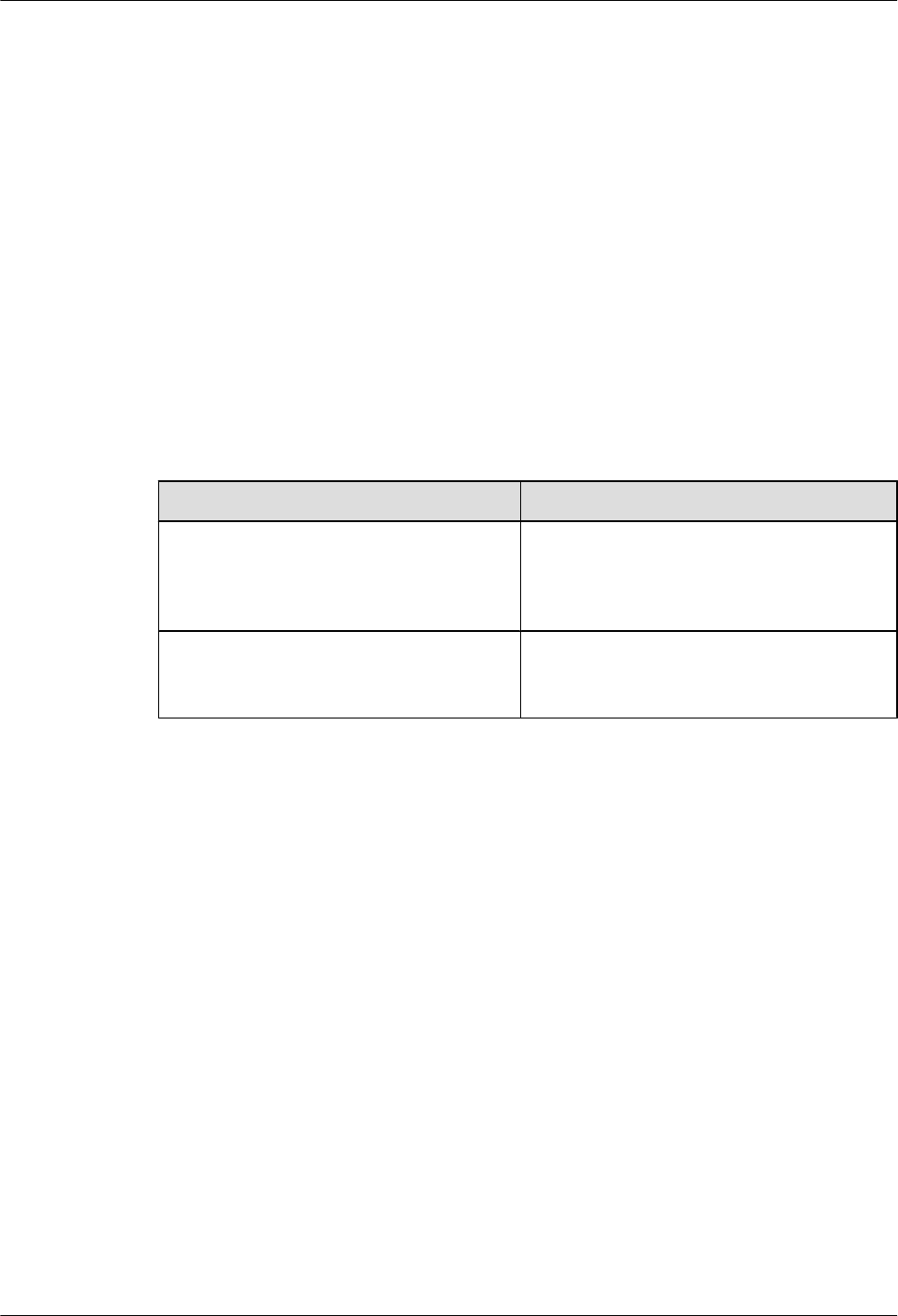
7.1 Failed Communication Between the SMT and the BTS
This describes the symptom of the communication failure between the SMT and the BTS and
analyzes the cause of the failed communication. It also provides the fault handling suggestions.
Fault Symptom
Log in to the BTS on the SMT fails. The result of running the ping commands shows that the
connection between the SMT PC and the BTS cannot be established.
Cause Analysis and Handling Suggestions
Table 7-1 lists the possible causes and related suggestions to handle the fault.
Table 7-1 Possible causes and handling suggestions for failed communication between the SMT
and the BTS
Fault Cause Handling Suggestion
The Ethernet cable is faulty. Check the connection of the Ethernet cable.
Check whether the RJ45 connectors on both
ends are functional. If the RJ45 connector is
faulty, replace it.
The IP address of the SMT PC is incorrect. Check whether the IP address of the SMT PC
is on the same network segment as that of the
board.
7.2 Faulty E1 Link
This describes the fault symptom and analyzes the cause of the faulty E1 link. It also provides
the fault handling suggestions.
Fault Symptom
Alarms related to the E1/T1 link are reported, or the upper link is faulty.
Analysis
When the E1 links are faulty, the cause may be one of the following:
lThe physical connection of cable is faulty.
lThe crossed pair connection exists.
lThe BER in transmission is high.
Handling Suggestion
1. Check the connections and connectors at both ends of the E1 link. Ensure that the
connections are reliable and the connectors are functional.
7 FAQs for BTS Commissioning
BTS3900(A) GSM
Commissioning Guide
7-2 Huawei Proprietary and Confidential
Copyright © Huawei Technologies Co., Ltd.
Issue 02 (2009-04-20)
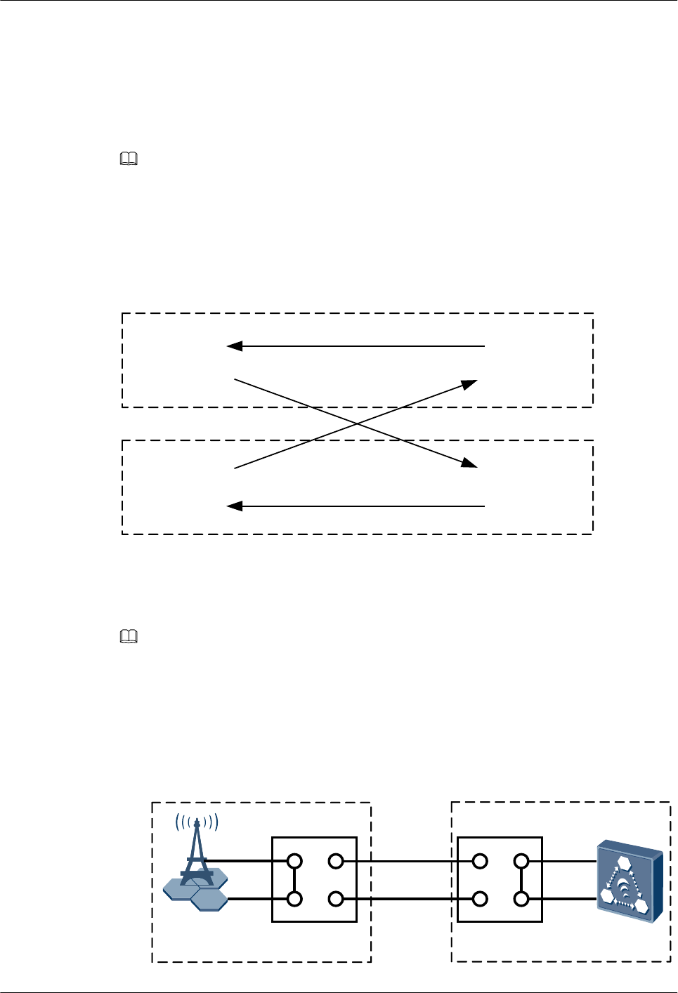
2. Check for the crossed pair connection on the LMT.
3. Perform a physical loopback test to check whether the transmission of the E1 cable is normal
on the BTS side.
4. Check the transmission channels to ensure that all the transmission channels are available.
Example One: Detection of Crossed Pair Connection
NOTE
The detection method in this example is applicable to check for the improper E1 connection between the
BTS and the BSC or the improper E1 connection on the BSC side. This detection method also can be used
to check the improper T1 connection.
The crossed pair connection refers to the incorrect RX and TX connections between two pairs
of E1 cables, as shown in Figure 7-1.
Figure 7-1 Crossed pair connection
E1 A E1 A
E1 B E1 B
RX
RX
RX
RXTX
TX
TX
TX
Perform the loopback method on the BSC side to check for crossed pair connection. Perform
different steps according to different E1 connection modes.
NOTE
Loopback test: Set the port on the BTS side to the directly physical loopback mode. Send the test data,
which carries the E1 port number, to the TX end of the E1 from the BSC side. After the loopback, check
whether the received port information is the same as the transmitted one. If yes, you can infer that the E1
cable is correctly connected. If not, you can infer that the crossed pair connection occurs.
lE1 link between the BTS and the BSC (1): BTS→DDF on the BTS side→DDF on the BSC
side→BSC, as shown in Figure 7-2.
Figure 7-2 E1 link between the BTS and the BSC (1)
BTS BSC
DDF0
E1/T1
E1/T1 E1/T1
E1/T1
DDF1
E1/T1
E1/T1
A1
B1
C1
D1
A0
B0
C0
D0
BTS3900(A) GSM
Commissioning Guide 7 FAQs for BTS Commissioning
Issue 02 (2009-04-20) Huawei Proprietary and Confidential
Copyright © Huawei Technologies Co., Ltd.
7-3
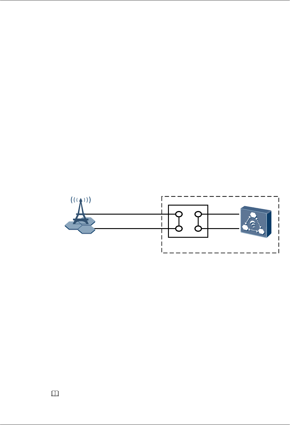
1. Check for the crossed pair connection on the E1 cable between the DDF on the BSC
side and the BSC.
(1) Perform a physical loopback on each E1 cable at the DDF subrack of the BSC,
as shown in Figure 7-2. Connect port C1 and port D1
(2) Run CHK E1T1CRS to query the results. If the results of all the ports are NOT
CROSS, you can infer that the E1 cable is correctly connected on the BSC side.
If the results are CROSS EXIST, correctly connect the E1 cable to this port.
(3) Restore the E1 connections between the BSC and the DDR. That is, connect port
C1 to port A1 and connect port D1 to port B1.
2. Check for the crossed pair connection on the E1 cable at the DDF subrack of the BSC.
That is, connect port A1 and port B1. The detection method is similar to that in 1.
3. Check for the crossed pair connection on the E1 cable between the DDF subrack of
the BTS and the DDF subrack of the BSC. That is, connect port C0 and port D0. The
detection method is similar to that in 1.
4. Check for the crossed pair connection on the E1 cable at the DDF subrack of the BTS.
That is, connect port A0 and port B0. The detection method is similar to that in 1.
lE1 link between the BTS and the BSC (2): BTS→DDF on the BSC side→BSC, as shown
in Figure 7-3.
Figure 7-3 E1 link between the BTS and the BSC (2)
BTS BSC
E1/T1
E1/T1
DDF
E1/T1
E1/T1
A
B
C
D
1. Check for the crossed pair connection on the E1 cable between the DDF subrack of
the BSC and the BSC.
(1) Perform a physical loopback on each E1 cable at the DDF subrack of the BSC,
as shown in Figure 7-2. Connect port C and port D.
(2) Run CHK E1T1CRS to query the results. If the results of all the ports are NOT
CROSS, you can infer that the E1 cable is correctly connected on the BSC side.
If the results are CROSS EXIST, correctly connect the E1 cable to this port.
(3) Restore the E1 connections between the BSC and the DDR subrack. That is,
connect port C to port A and connect port D to port B.
2. Check for the crossed pair connection on the E1 cable at the DDF subrack of the BSC.
That is, connect port A and port B. For details, see 1.
Example Two: Check for UELP Faults Through Physical Loopback Test
NOTE
The physcial loopback test in this example is applicable to check for the improper E1 connection on the
BTS side.
7 FAQs for BTS Commissioning
BTS3900(A) GSM
Commissioning Guide
7-4 Huawei Proprietary and Confidential
Copyright © Huawei Technologies Co., Ltd.
Issue 02 (2009-04-20)
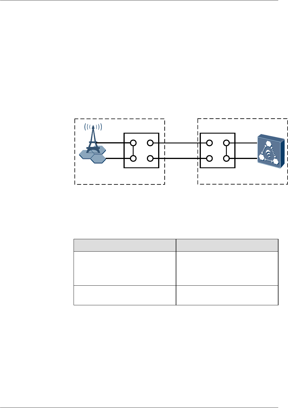
1. Ensure that the E1/T1 cable is securely connected to the OUTSIDE port on the UELP, and
that the connectors are in sound condition. If the connector is damaged, replace it.
2. Ensure that the E1 transfer cable is securely connected to the INSIDE port on the UELP
and the E1/T1 port on the GTMU, and that the connectors are in sound condition. If the
connector is damaged, replace it.
3. Perform the physical loopback test and troubleshoot the fault in the UELP.
(1) Perform a physical loopback on the BTS side. In general, for a pair of E1s/T1s
connecting the BTS and BSC through the DDF, port A0 is connected to port C0, and
port B0 is connected to port D0. In the loopback test, disconnect port A0 from port
C0, and port B0 from port D0, and then connect port A0 to port B0, as shown in Figure
7-4. In this way, the physical loopback is formed on the BTS side.
Figure 7-4 Physical loopback of E1/T1 on the BTS side
BTS BSCDDF0
E1/T1
E1/T1 E1/T1
E1/T1
DDF1
E1/T1
E1/T1
A1
B1
C1
D1
A0
B0
C0
D0
(2) You need check the state of the LIU LEDs corresponding to the E1/T1 in use, as
shown in Table 7-2.
Table 7-2 Meaning of the state of the LIU LEDs (UELP used)
If... Then...
The LEDs are OFF The cable connections on the BTS side
are operational. The fault of the UELP
is cleared. The testing task on the BTS
side is complete.
The LEDs are ON or ON for 0.125s and
OFF for 0.125s
The cable connections on the BTS side
are faulty. Clear the fault of the UELP.
(3) Disconnect the E1 transfer cable and the E1/T1 cable. Then, directly connect the E1/
T1 cable to the E1/T1 port on the GTMU.
(4) When the UELP is not used, determine whether the E1/T1 link is normal based on the
state of the LIU LEDs on the GTMU panel, as listed in Table 7-3.
BTS3900(A) GSM
Commissioning Guide 7 FAQs for BTS Commissioning
Issue 02 (2009-04-20) Huawei Proprietary and Confidential
Copyright © Huawei Technologies Co., Ltd.
7-5
Table 7-3 Meaning of the state of the LIU LEDs (UELP not used)
If... Then...
The LEDs are OFF The UELP is faulty.
a. Check whether the connection
between the UELP and the backplane
of the BBU is reliable.
b. Replace the UELP.
The LEDs are ON or ON for 0.125s and
OFF for 0.125s
The UELP is functional, but the E1 link
on the BTS side is faulty.
(5) Reconnect the E1/T1 cable to the OUTSIDE port on the UELP and ensure that the
connection is proper.
(6) Reconnect the E1/T1 cable to the INSIDE port on the UELP and the E1/T1 port on
the GTMU, and ensure that the connection is proper.
CAUTION
After the physical loopback test, set the E1/T1 at the DDF on the BTS side from physical
loopback to normal connection. Ensure that the connections are sound.
7.3 Failure of an MS to Search the Network
This describes the fault symptom and analyzes the cause of the failure of an MS to search the
network.
Fault Symptom
An MS fails to find the network.
Cause Analysis
The possible causes are as follows:
lCell parameters such as CGI, BCCH, TA, and BSIC are improperly configured.
lThe MS does not support the frequency band of this base station.
lThe downlink signals are weak. Therefore, the MS is unable to locate the cell.
lThe downlink interference is strong. The MS is unable to locate the cell or receive the
correct downlink system information.
lThe cell radius is small.
NOTE
When the MS fails to find the network, pay attention to the output power of the local cell and the radio
network coverage.
7 FAQs for BTS Commissioning
BTS3900(A) GSM
Commissioning Guide
7-6 Huawei Proprietary and Confidential
Copyright © Huawei Technologies Co., Ltd.
Issue 02 (2009-04-20)
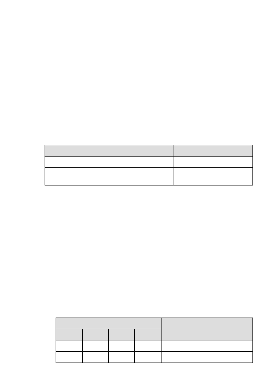
7.4 Service Dialing Failure
This describes the fault symptom and analyzes the cause of the service dialing failure. It also
provides the fault handling suggestions.
Fault Symptom
Service dialing failure may occur in either of the following cases:
lLocation update failure
lService dialing failure
Cause Analysis and Handling Suggestion
Table 7-4 lists the possible causes and related suggestions.
Table 7-4 Possible causes and handling suggestions for service dialing failure
Cause of the Fault Handling Suggestion
The MS is faulty. Replace the MS with a new one.
The CS domain or the PS domain on the CN side is not
ready.
Keep the CS domain and the PS
domain ready.
7.5 Low GPRS Data Transmission Rate
This describes the fault symptom and analyzes the cause of low GPRS data transmission rate.
Fault Symptom
During the service test, the following problems may occur: low GPRS data rate in the PS domain
of the newly added BTS, or a high BER on the Abis interface.
Cause Analysis
The possible causes are as follows:
lThe E1 cable is not properly grounded. You can enable the grounding status of the E1 cable
by setting the DIP switch SW2 on the GTMU. Table 7-5 describes the DIP switch SW2.
Table 7-5 Description of the DIP switch SW2 on the GTMU
Setting of DIP Bit Description
1 2 3 4
ON ON ON ON The E1 cable is grounded.
OFF OFF OFF OFF The E1 cable is not grounded.
BTS3900(A) GSM
Commissioning Guide 7 FAQs for BTS Commissioning
Issue 02 (2009-04-20) Huawei Proprietary and Confidential
Copyright © Huawei Technologies Co., Ltd.
7-7

If... Then...
Only one end of the E1 cable is grounded, The E1 cable is grounded properly.
Both ends of the E1 cable are grounded, The E1 cable is not grounded properly.
lThe data configuration negotiated between the BSC and the BTS is not consistent.
lThe cell signals are weak.
lThe MS capability is limited.
7 FAQs for BTS Commissioning
BTS3900(A) GSM
Commissioning Guide
7-8 Huawei Proprietary and Confidential
Copyright © Huawei Technologies Co., Ltd.
Issue 02 (2009-04-20)
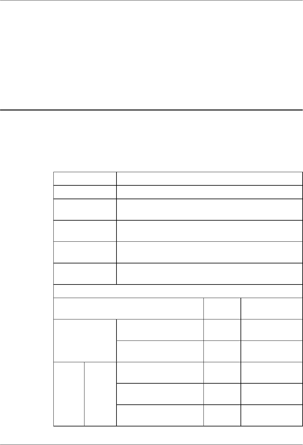
8 Commissioning Record Data Sheet
This describes the data sheet that is used to record the process and result of the BTS
commissioning.
Table 8-1 Data sheet for BTS commissioning
Site Name
BTS Model
Commissioning
Time
Commissioning
Engineer
Scenario □ Transmission available scenario □ Transmission unavailable
scenario
Commissioning
Result
□ Successful □ Failed
Commissioning Item Conclusion Handling
Exceptional Case
Commissioning
Preparation Phase
The resources required for
commissioning are available.
The commissioning
requirements are met.
Commis
sioning
Phase
Transmis
sion
Unavaila
ble Phase
You have logged in to the BTS
through the SMT.
The BTS board and logical
objects are available.
The current software version is
correct.
BTS3900(A) GSM
Commissioning Guide 8 Commissioning Record Data Sheet
Issue 02 (2009-04-20) Huawei Proprietary and Confidential
Copyright © Huawei Technologies Co., Ltd.
8-1

The transmission between the
BBU and the RXU is normal.
No other alarms are reported
except the alarms related to the
transmission.
The hardware connections are
correct.
Site management rights are
released.
The transmission between the BBU and the
BSC is available.
Transmis
sion
Availabl
e Phase
(on the
LMT)
The transmission between the
BBU and the RXU and the
transmission between the BBU
and the BSC is normal.
The transmission between
cascaded BTSs is normal.
The transmission between
BTSs in ring topology is
normal.
The board configuration is
correct and the boards are in
normal operation.
The current software version is
correct.
The hardware installation and
the data configuration are
consistent with each other.
No alarms related to the BTS
are reported.
The CS service test is
successful.
The PS service test is
successful.
The environment monitoring
alarm is reported normally.
Optional
Commiss
ioning
Task
The VSWR is correct. Record
the value of the VSWR.
The output power of the TRX
is normal. Record the value of
the output power per carrier.
8 Commissioning Record Data Sheet
BTS3900(A) GSM
Commissioning Guide
8-2 Huawei Proprietary and Confidential
Copyright © Huawei Technologies Co., Ltd.
Issue 02 (2009-04-20)
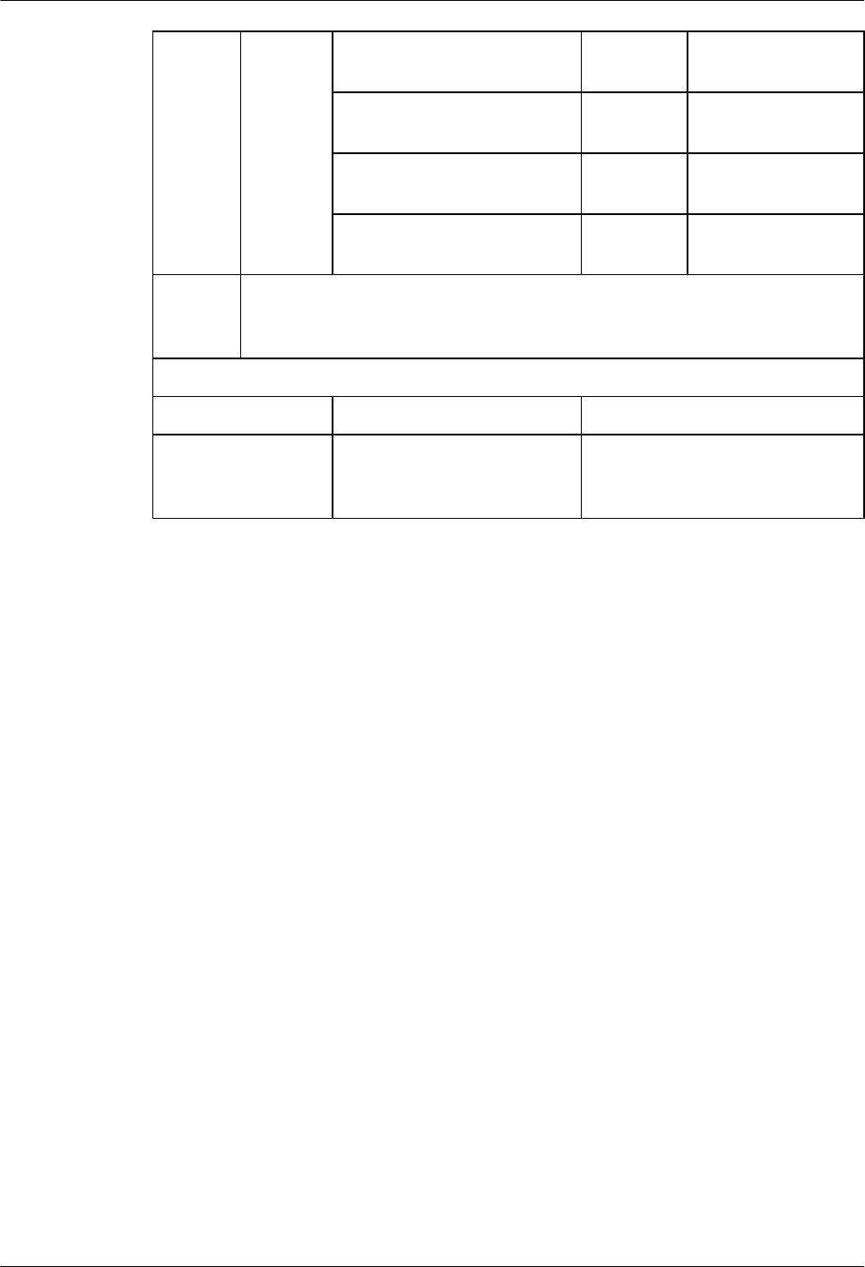
The antenna system is properly
connected.
The result of the carrier
loopback test is normal.
The result of the channel
loopback test is normal.
The DIP switch settings are
correct.
Commis
sioning
Result
Unsolved Problems Impact
Unsolved Problems
After
Commissioning
BTS3900(A) GSM
Commissioning Guide 8 Commissioning Record Data Sheet
Issue 02 (2009-04-20) Huawei Proprietary and Confidential
Copyright © Huawei Technologies Co., Ltd.
8-3
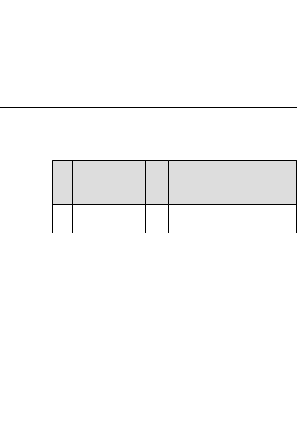
9 Communication Ports Used by the GBTS
Table 9-1 lists the communication port used by the GBTS
Table 9-1 The Communication Port Used by GBTS
Prot
ocol
Side
A
Side
A
Ports
(Liste
ning)
Side B Side
B
Ports
(Lau
nch)
Service Authe
nticati
on
TCP GBT
S
700 SMT 1024-
65535
It will be used by SMT for local
maintenance before GBTS connects
in the network
-
BTS3900(A) GSM
Commissioning Guide 9 Communication Ports Used by the GBTS
Issue 02 (2009-04-20) Huawei Proprietary and Confidential
Copyright © Huawei Technologies Co., Ltd.
9-1