Huawei Technologies PRRU3901 pico Remote Radio Unit User Manual Installation Guide
Huawei Technologies Co.,Ltd pico Remote Radio Unit Installation Guide
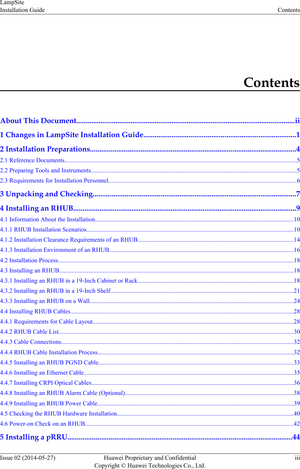
Contents
- 1. UserManual_LampSite Installation Guide(02)(PDF)-EN.pdf
- 2. UserManual_pRRU3901 Compliance and Safety Manual.pdf
- 3. UserManual_LampSite Site Maintenance Guide(02)(PDF)-EN.pdf
UserManual_LampSite Installation Guide(02)(PDF)-EN.pdf

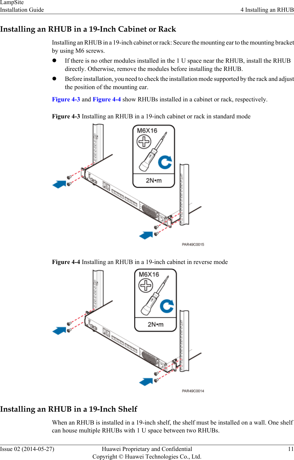

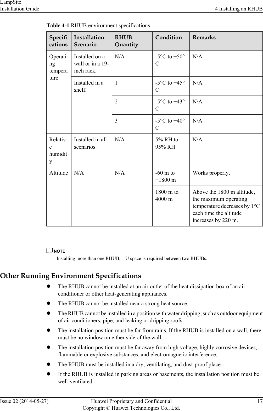
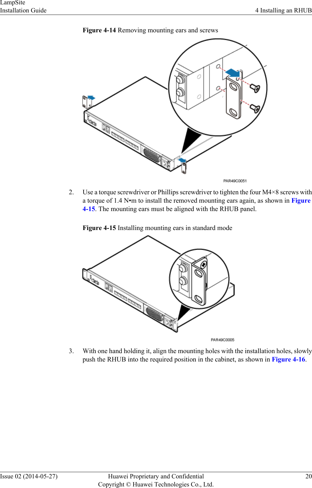
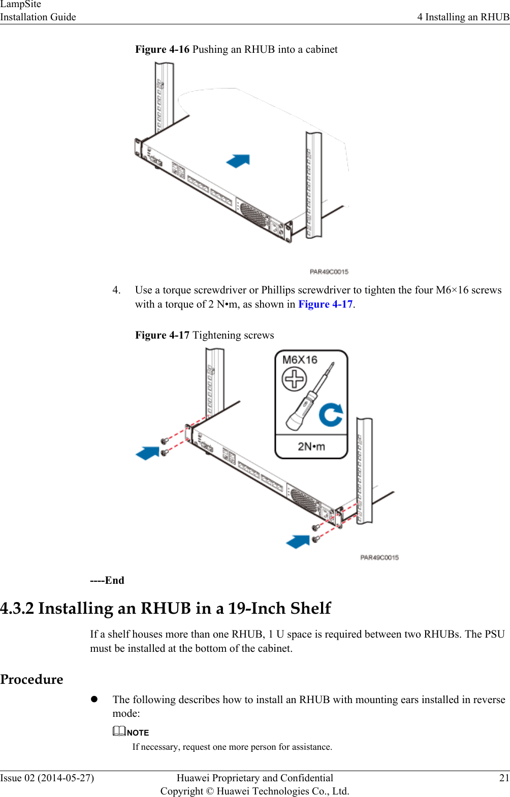
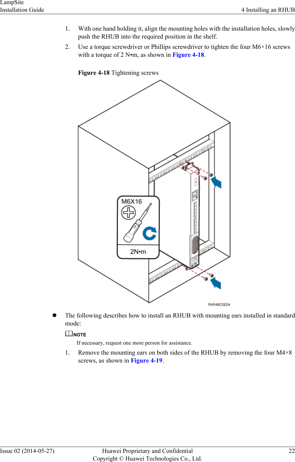
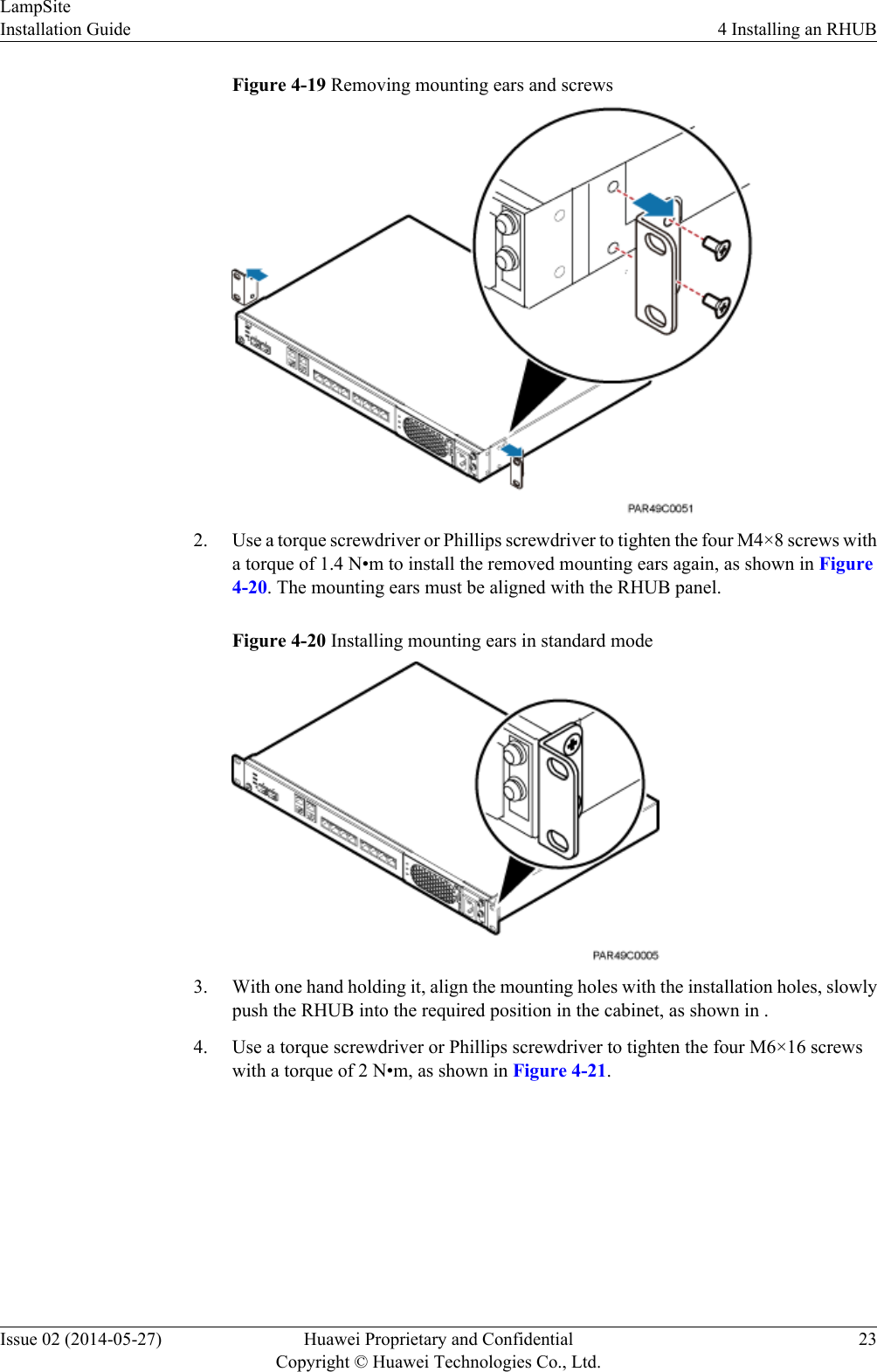
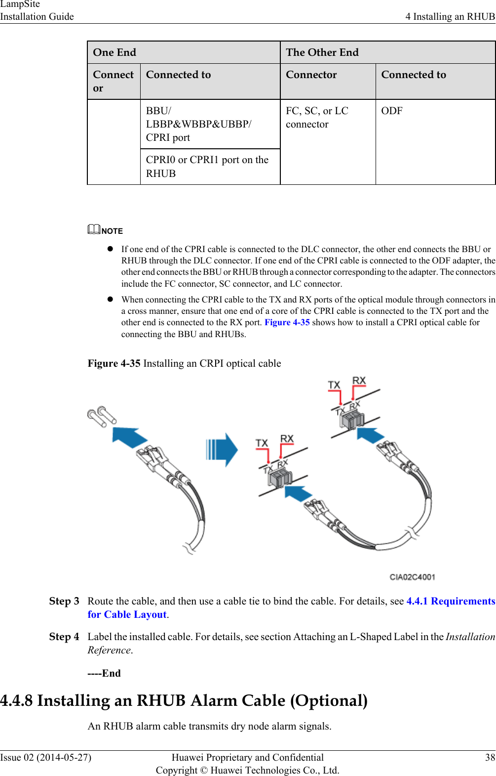
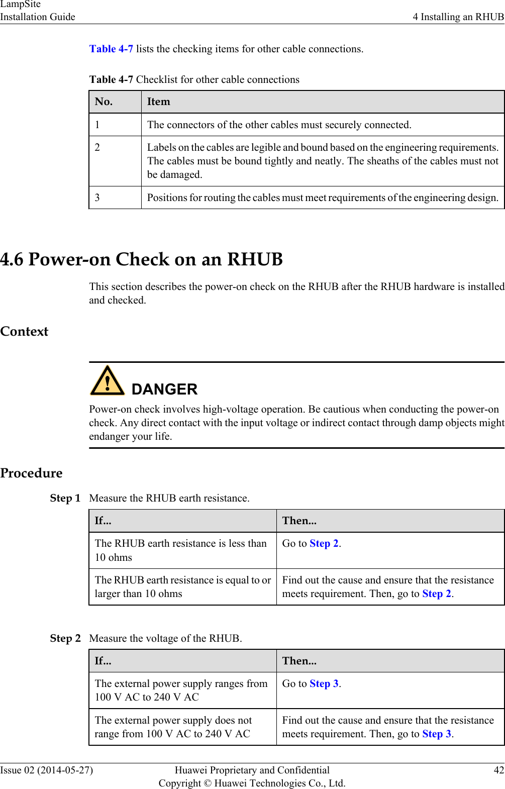
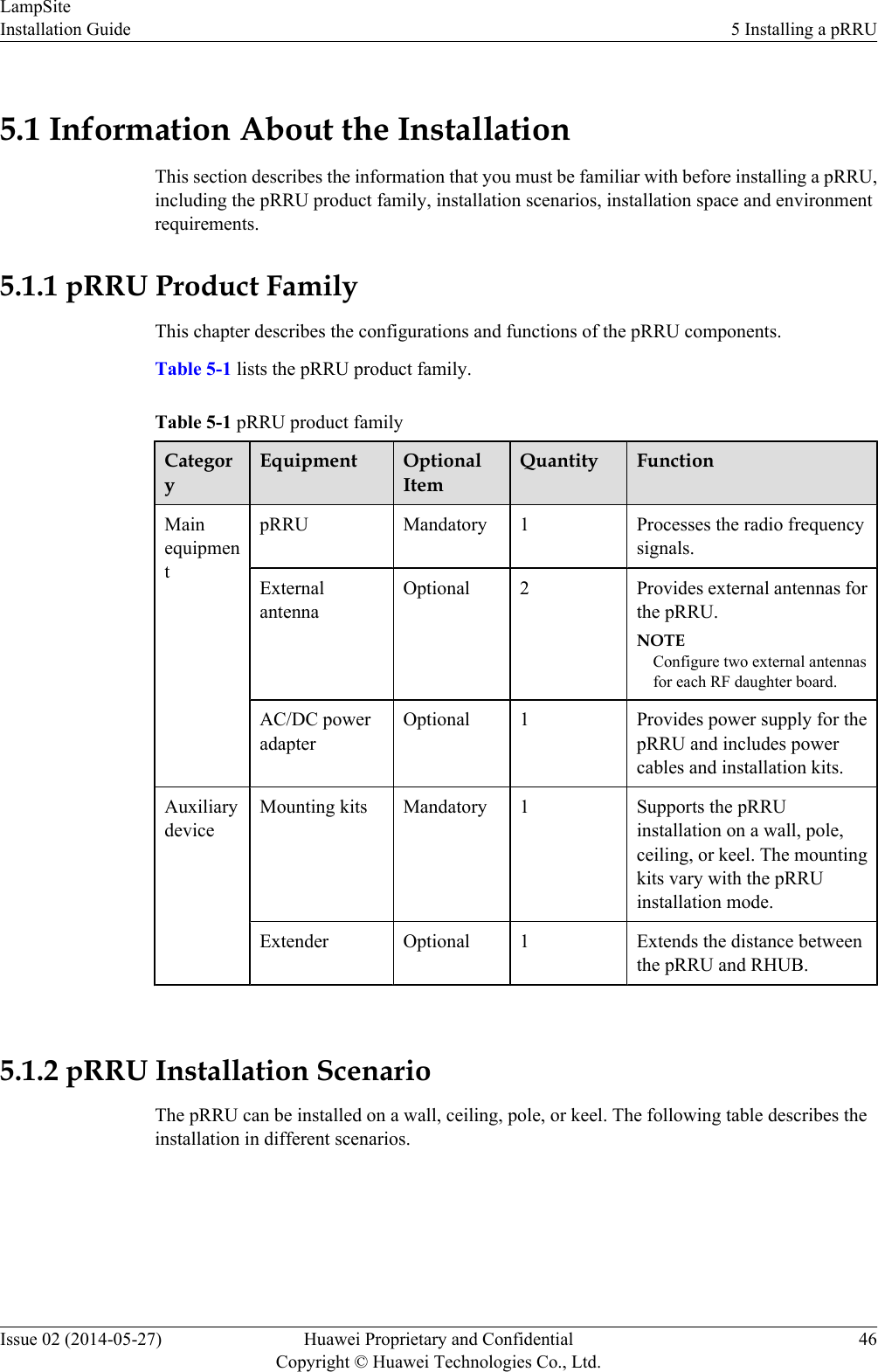
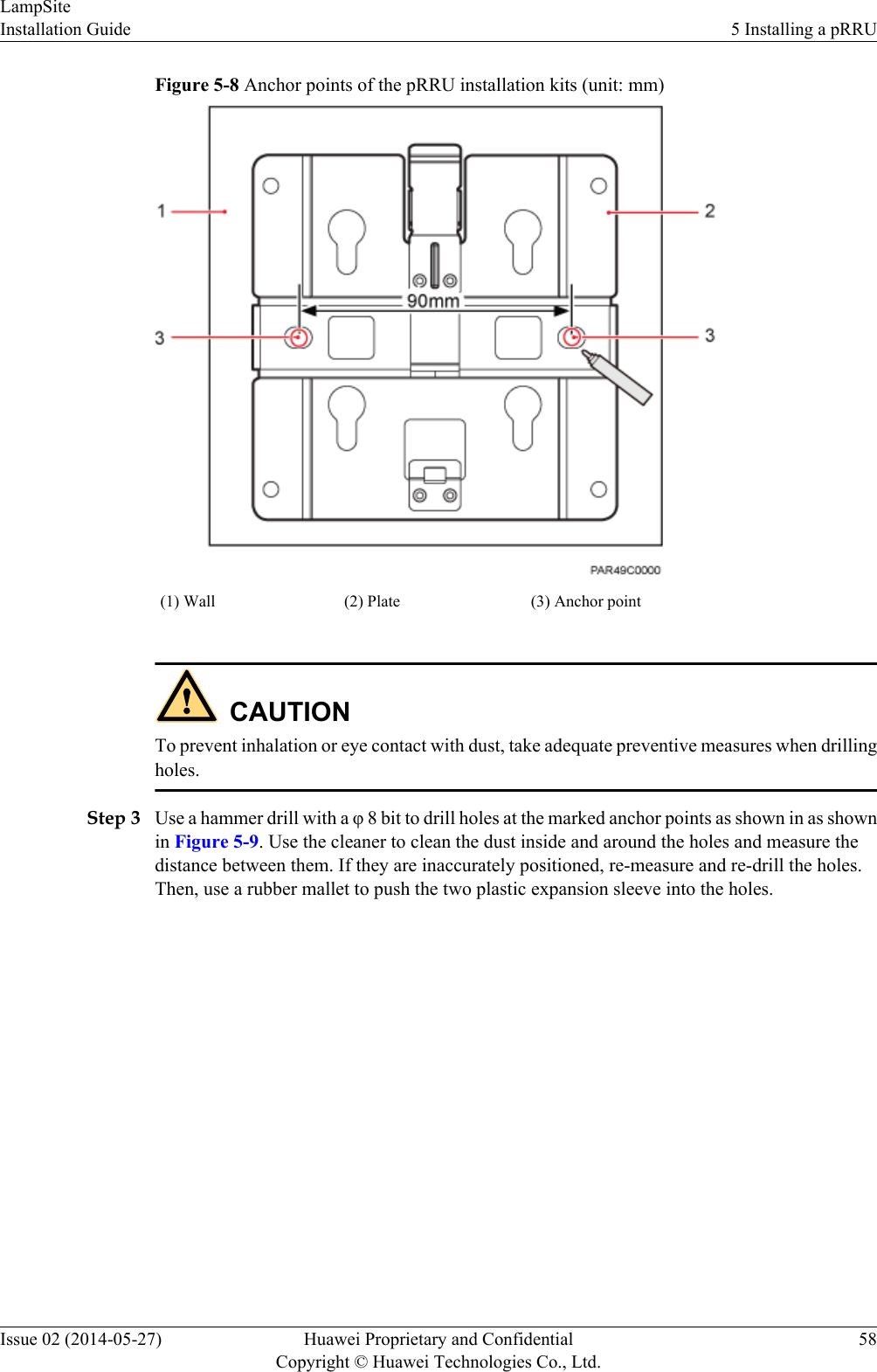
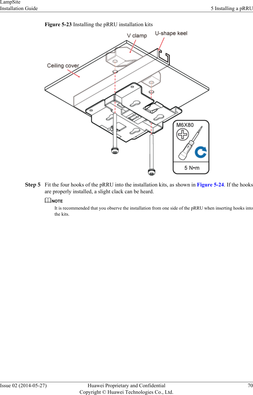
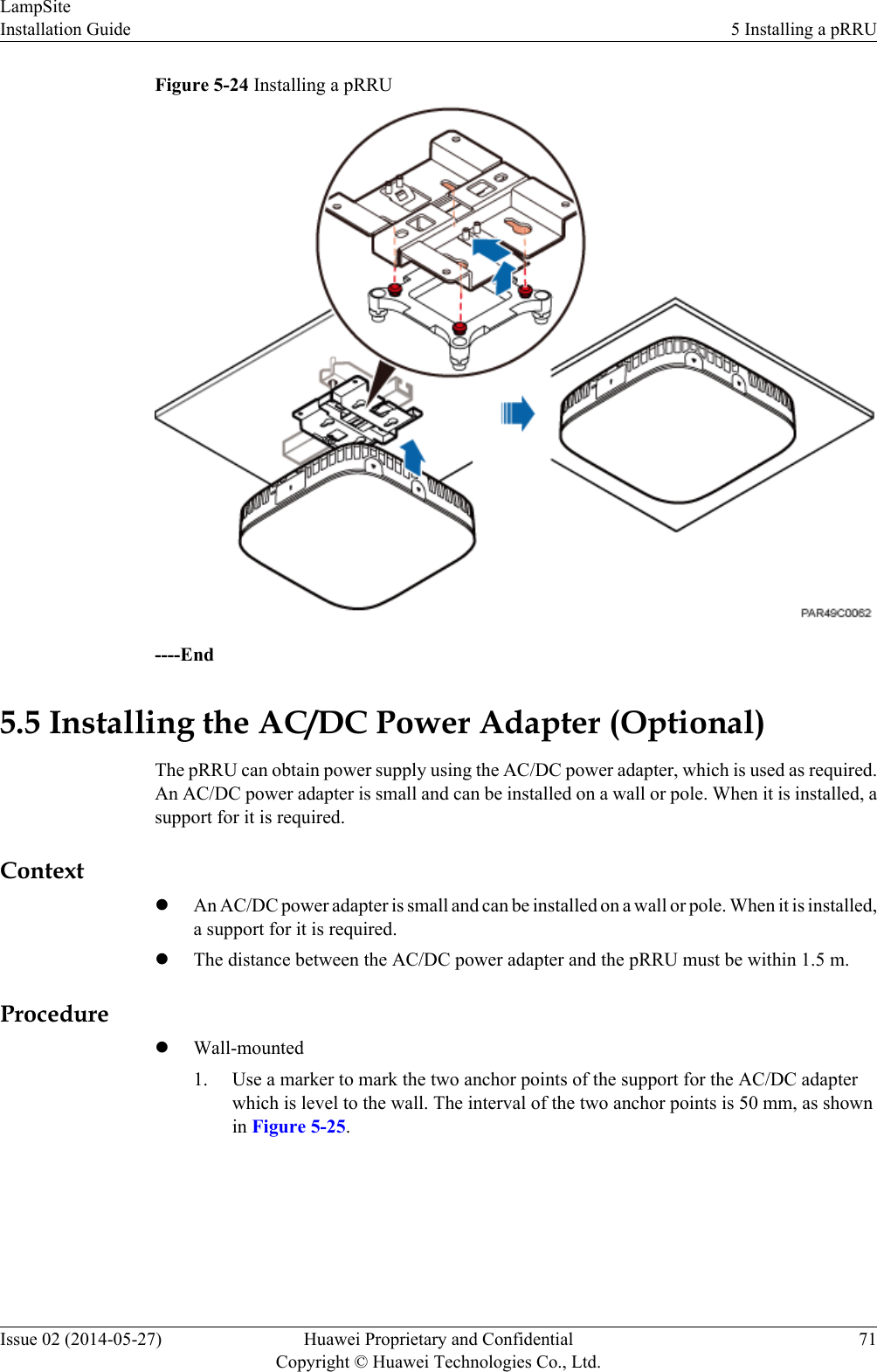
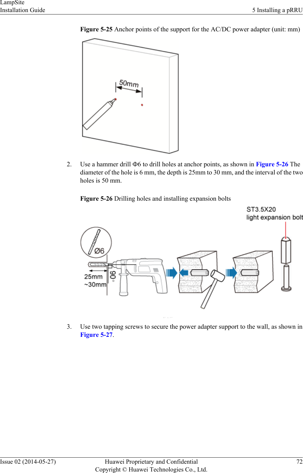
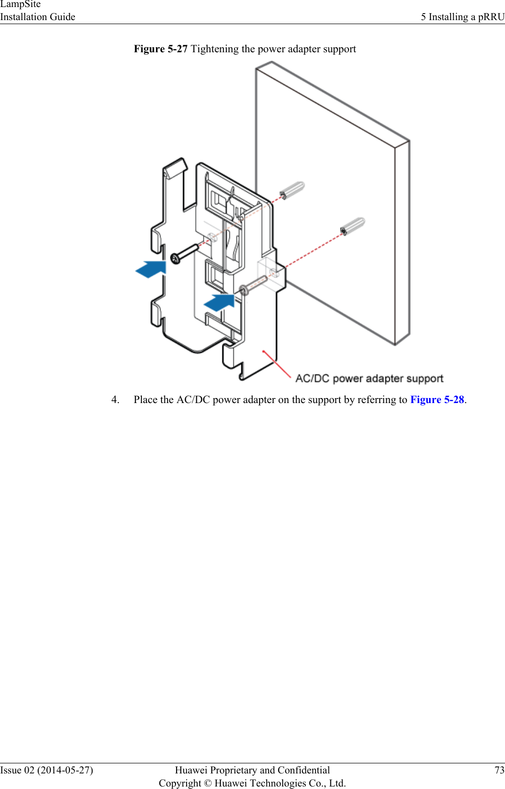
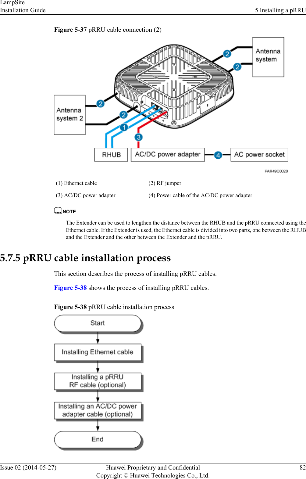
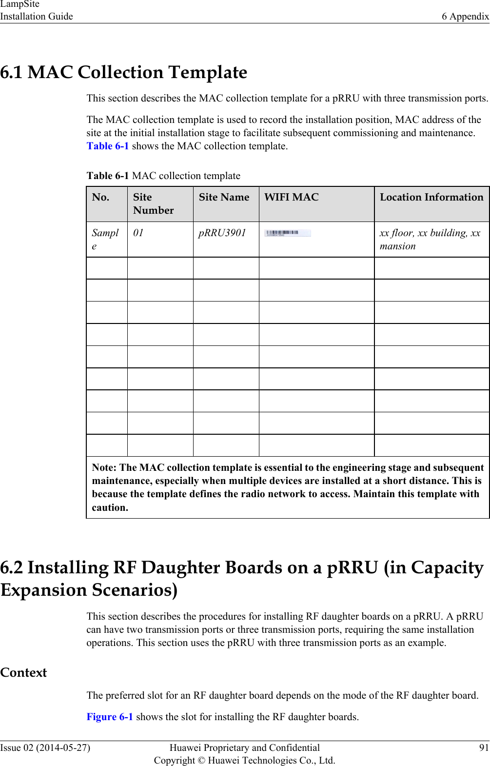
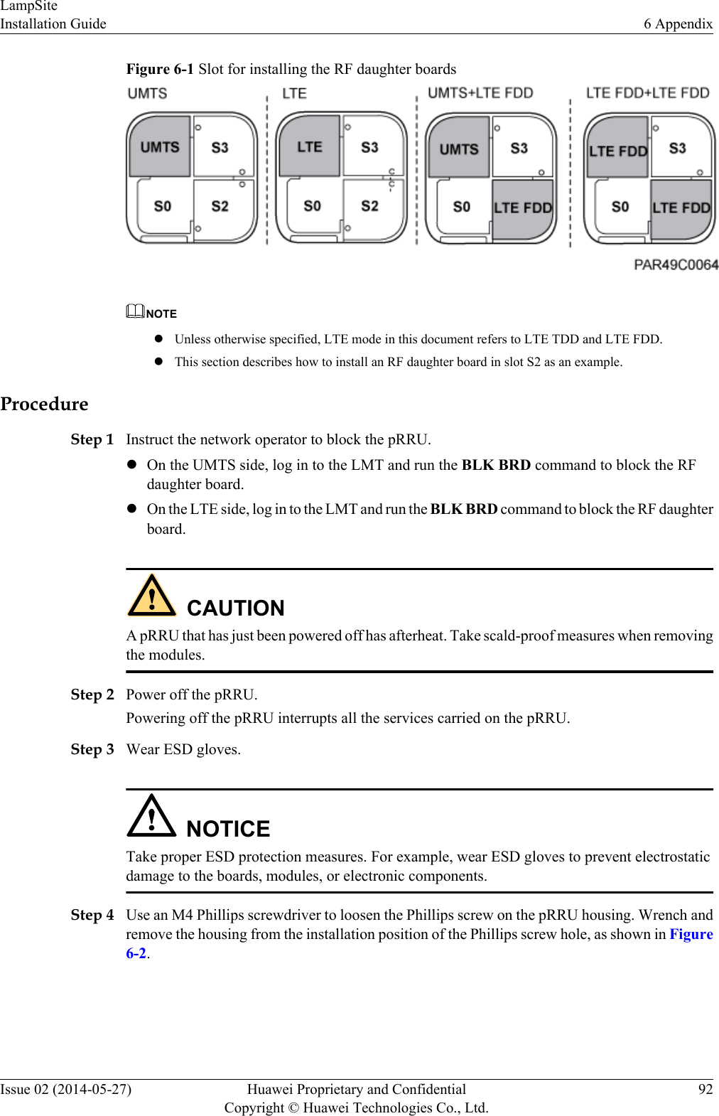
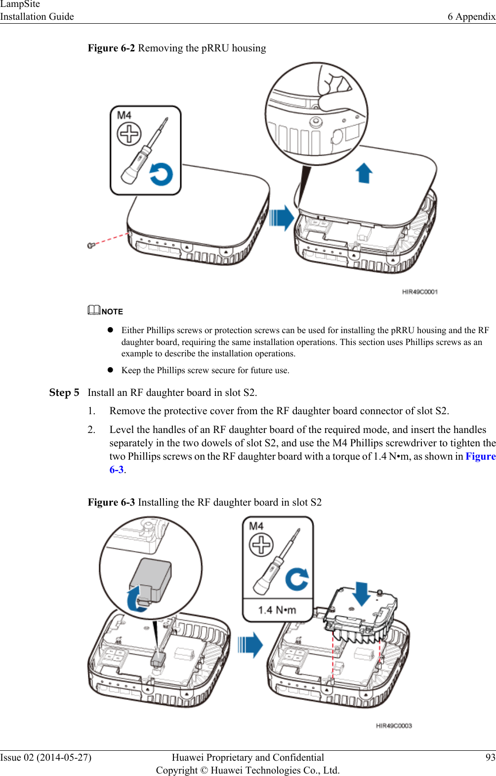
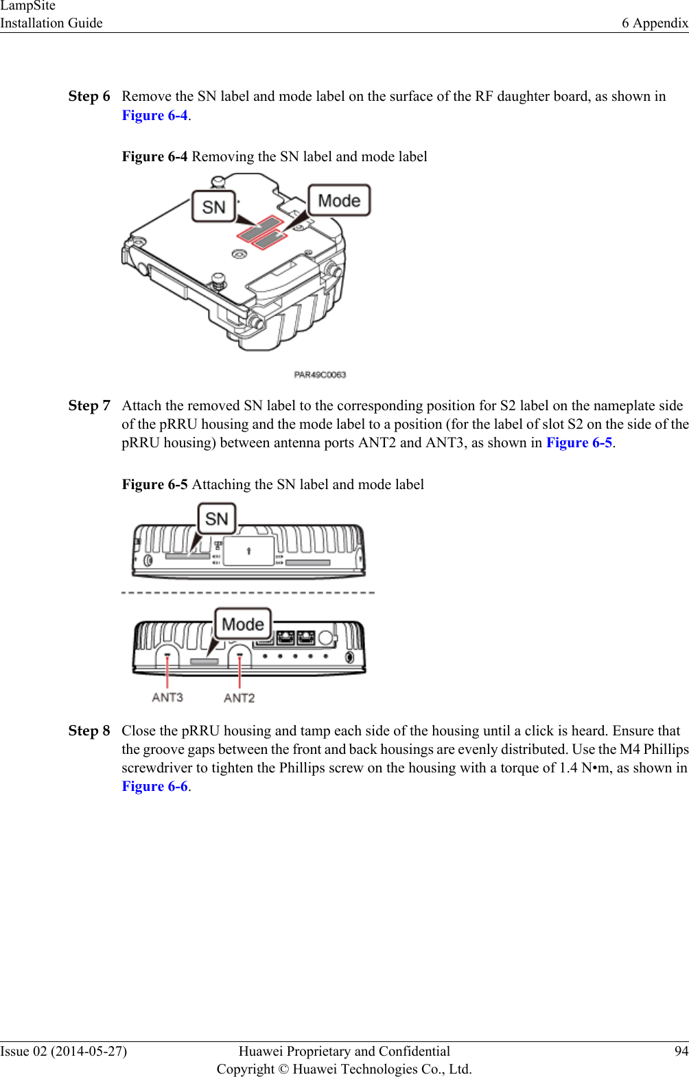
![Table 4-2 RHUB cable listCable One End The Other EndConnector Connectedto...Connector Connected to...PGND cable OT terminal (M4,6 mm2 [0.009 in.2])Ground screwson the RHUBOT terminal(M6, 6 mm2[0.009 in.2])Ground terminalon the externalground barRHUB powersupply cableC13 femaleconnectorAC powerinput socket onthe RHUB3-pin connector External powerinput socketCPRI opticalfiberDLC connector CPRI port onthe LBBP,WBBP orUBBP in theBBUDLC connector CPRI0 or CPRI1port on the RHUBCPRI0 orCPRI1 port onthe RHUBDLC connector CPRI0 or CPRI1port on the RHUBCPRI port onthe LBBP,WBBP orUBBP in theBBUFC connector,SC connector, orLC connectorODFCPRI0 orCPRI1 port onthe RHUBFC connector,SC connector, orLC connectorODFEthernetcableRJ45 connector CPRI_E0~CPRI_E7 port onthe RHUBRJ45 connector CPRI_E0~CPRI_E1 port on thepRRU(Optional)RHUB alarmcableRJ45 connector EXT_ALMport on theRHUBBare end Alarm signal portof the backuppower system NOTElIf one end of the CPRI cable is connected to the DLC connector, the other end connects the BBU, orRHUB through the DLC connector. If one end of the CPRI cable is connected to the ODF adapter, theother end connects the BBU or RHUB through a connector corresponding to the adapter. The connectorsinclude the FC connector, SC connector, and LC connector.lThe Extender can be used to lengthen the distance between the RHUB and the pRRU connected usingthe Ethernet cable. If the Extender is used, the Ethernet cable is divided into two parts, one betweenthe RHUB and the Extender and the other between the Extender and the pRRU.LampSiteInstallation Guide 4 Installing an RHUBIssue 02 (2014-05-27) Huawei Proprietary and ConfidentialCopyright © Huawei Technologies Co., Ltd.31](https://usermanual.wiki/Huawei-Technologies/PRRU3901.UserManual-LampSite-Installation-Guide-02-PDF-EN-pdf/User-Guide-2306807-Page-36.png)
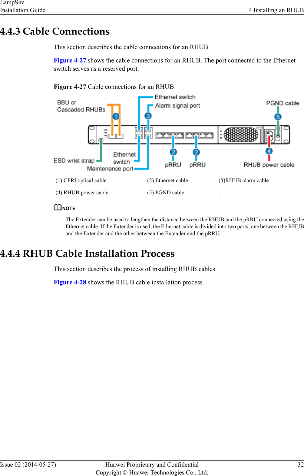
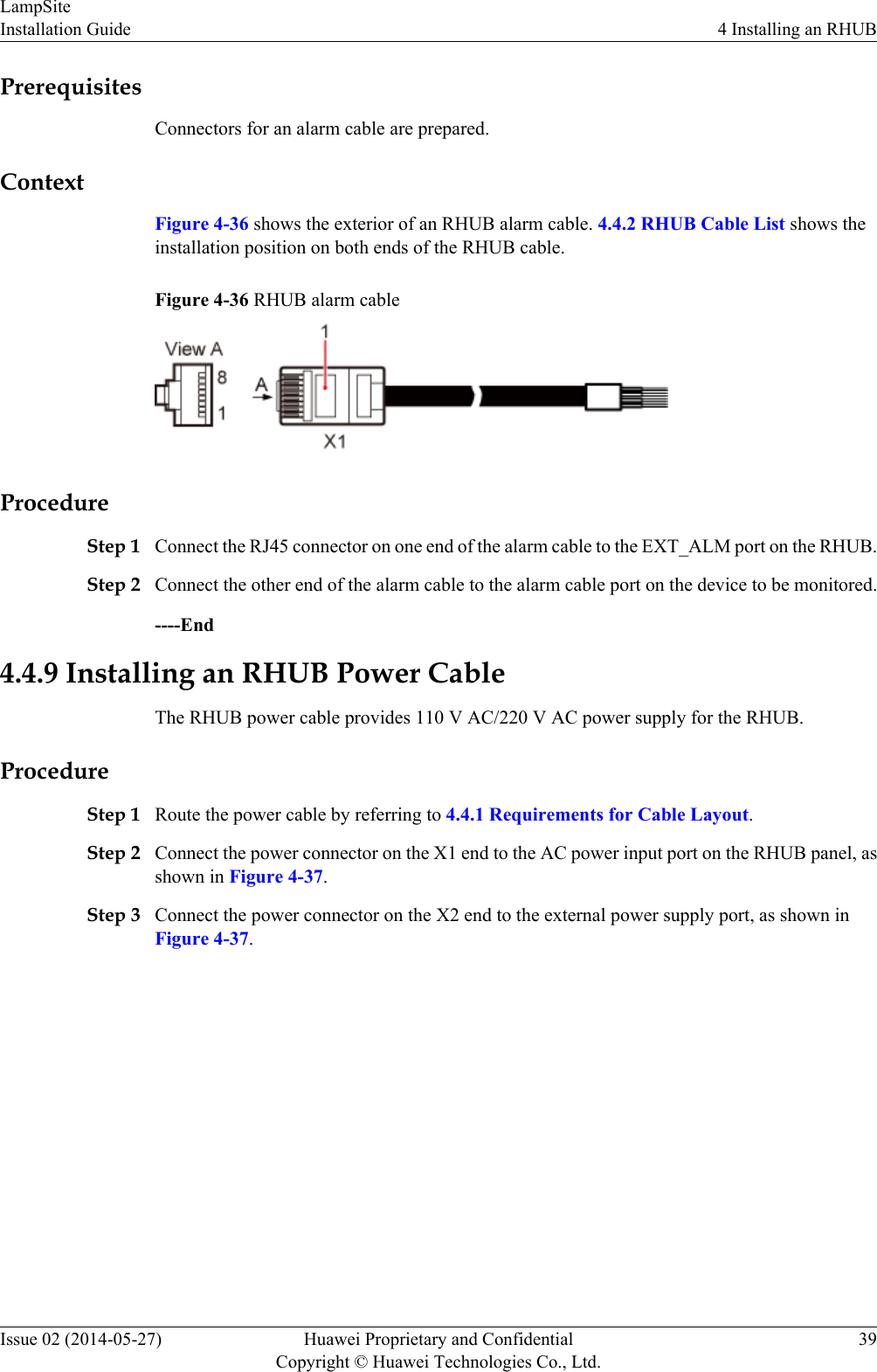
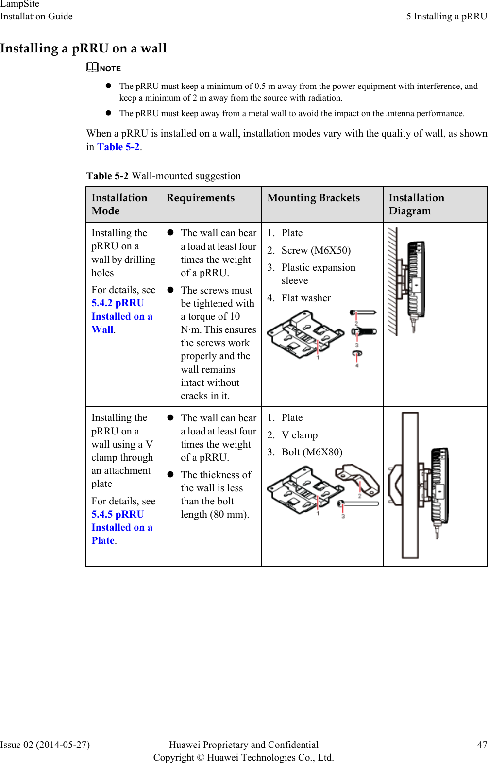
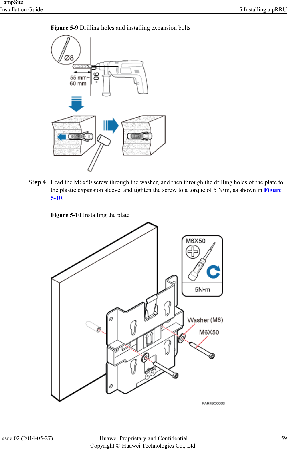
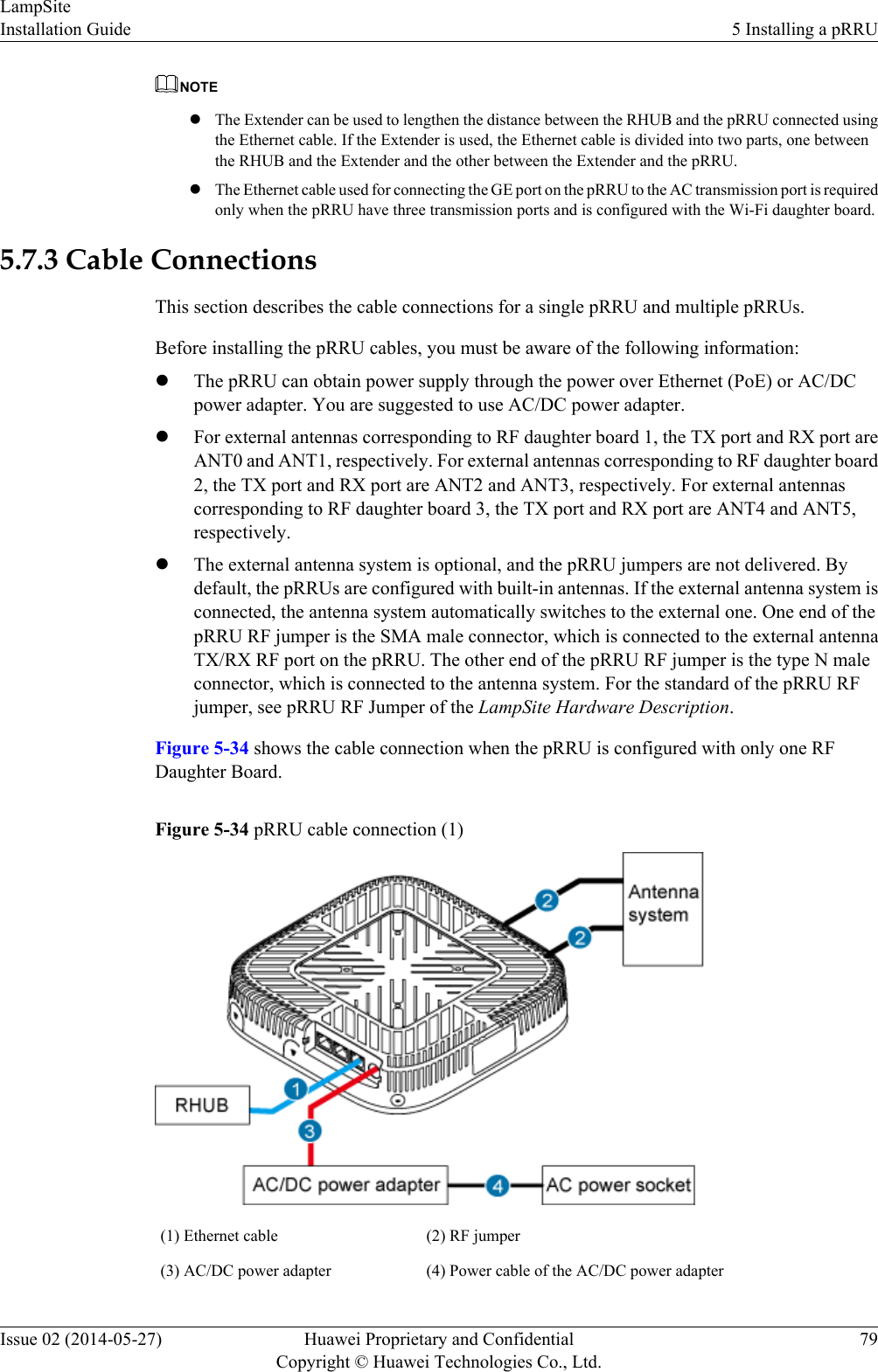
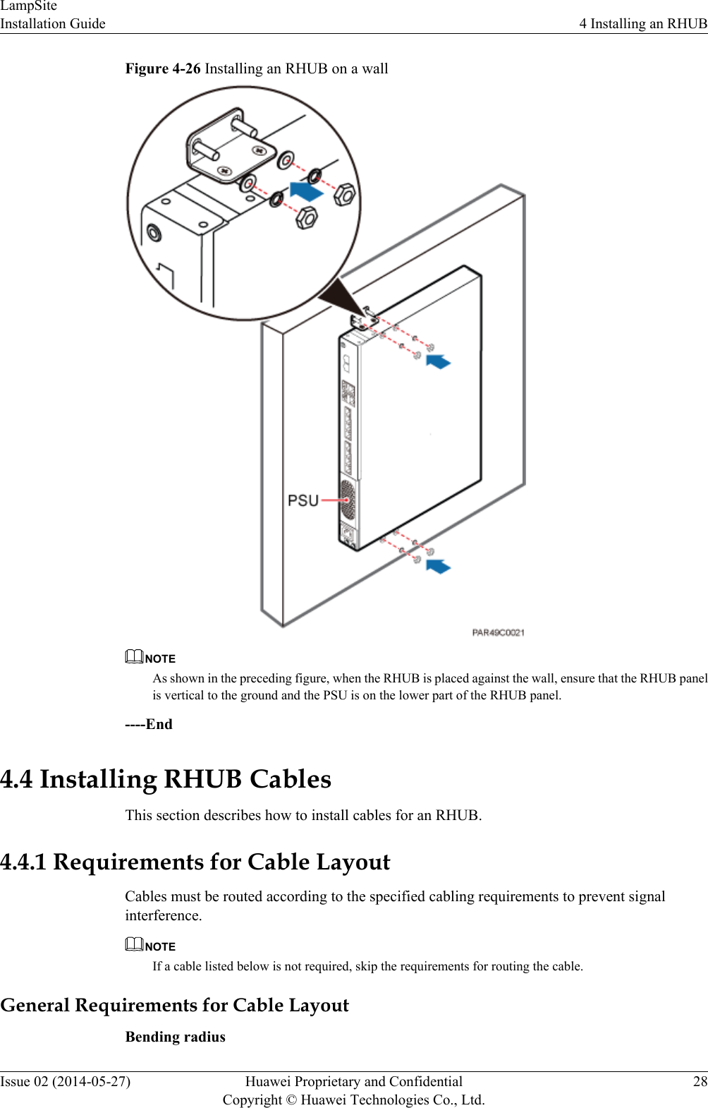
![Figure 4-28 RHUB cable installation process4.4.5 Installing an RHUB PGND CableAn RHUB PGND cable ensures proper grounding of an RHUB.PrerequisitesThe OT terminals at both ends of the PGND cable are prepared.ContextThe yellow and green or green PGND cable is a single cable. The cross-sectional area of thePGND cable is 6 mm2 (0.009 in.2). Both ends of the cable are OT terminals, as shown in Figure1.Figure 4-29 Exterior of a PGND cable(1) OT terminal (6 mm2 [0.009 in.2], M4) (2) OT terminal (6 mm2 [0.009 in.2], M6)LampSiteInstallation Guide 4 Installing an RHUBIssue 02 (2014-05-27) Huawei Proprietary and ConfidentialCopyright © Huawei Technologies Co., Ltd.33](https://usermanual.wiki/Huawei-Technologies/PRRU3901.UserManual-LampSite-Installation-Guide-02-PDF-EN-pdf/User-Guide-2306807-Page-38.png)