Huawei Technologies PRRU3901 pico Remote Radio Unit User Manual Site Maintenance Guide

Huawei Technologies Co.,Ltd pico Remote Radio Unit Site Maintenance Guide

UserManual_LampSite Site Maintenance Guide(02)(PDF)-EN.pdf
LampSiteSite Maintenance GuideIssue 02Date 2014-05-27HUAWEI TECHNOLOGIES CO., LTD.
  Copyright © Huawei Technologies Co., Ltd. 2014. All rights reserved.No part of this document may be reproduced or transmitted in any form or by any means without prior writtenconsent of Huawei Technologies Co., Ltd. Trademarks and Permissions and other Huawei trademarks are trademarks of Huawei Technologies Co., Ltd.All other trademarks and trade names mentioned in this document are the property of their respective holders. NoticeThe purchased products, services and features are stipulated by the contract made between Huawei and thecustomer. All or part of the products, services and features described in this document may not be within thepurchase scope or the usage scope. Unless otherwise specified in the contract, all statements, information,and recommendations in this document are provided "AS IS" without warranties, guarantees or representationsof any kind, either express or implied.The information in this document is subject to change without notice. Every effort has been made in thepreparation of this document to ensure accuracy of the contents, but all statements, information, andrecommendations in this document do not constitute a warranty of any kind, express or implied.       Huawei Technologies Co., Ltd.Address: Huawei Industrial BaseBantian, LonggangShenzhen 518129People's Republic of ChinaWebsite: http://www.huawei.comEmail: support@huawei.comIssue 02 (2014-05-27) Huawei Proprietary and ConfidentialCopyright © Huawei Technologies Co., Ltd.i
About This DocumentOverviewThis document describes routine maintenance items for a RHUB3908 and pRRU3901, such asequipment maintenance, and power-on and power-off operations. It also explains how to replacethe components and modules.Product VersionThe following table lists the product version related to this document.Product Name Product VersionRHUB3908 (referred to as RHUB in thisdocument)V100R009C00 and later versionsSingle-mode versions mappingV100R009C00:lNodeB: V200R016C00leNodeB: V100R007C00pRRU3901 (referred to as pRRU in thisdocument) Intended AudienceThis document is intended for:lSystem engineerslSite maintenance engineersOrganization1 Changes in LampSite Site Maintenance GuideThis chapter provides information about the changes in different document versions of LampSiteSite Maintenance Guide.2 RHUB Maintenance ItemsLampSiteSite Maintenance Guide About This DocumentIssue 02 (2014-05-27) Huawei Proprietary and ConfidentialCopyright © Huawei Technologies Co., Ltd.ii
This chapter describes the RHUB maintenance items, involving the equipment room, equipment,power system, and grounding system.3 pRRU Maintenance ItemsThis chapter describes the pRRU maintenance items, involving equipment and power system.4 Powering On and Powering Off the RHUBAfter the RHUB is powered on, check the indicator status. Power off the RHUB in normal oremergency mode as required.5 Powering On and Powering Off the pRRUAfter the pRRU is powered on, check the power supply voltage and indicator status. Power offthe pRRU based on the power supply mode.6 Replacing the RHUBThe RHUB is an indoor convergence unit. It converges multiple pRRUs to the BBU. Replacingthe RHUB interrupts services carried on the serving cell.7 Replacing an Optical ModuleAn optical module provides a port for opto-electronic conversion. This enables the transmissionbetween the RHUB and BBU through the optical fiber. Replacing the optical module requiresremoving the optical fibers. This interrupts all the services.8 Replacing the RF Daughter BoardThis section describes the procedures for replacing the RF daughter board of the pRRU. A pRRUcan have two transmission ports or three transmission ports, requiring the same installationoperations. This section uses the pRRU with three transmission ports as an example. Replacingan RF daughter board interrupts all the services carried on the pRRU.9 Replacing the Wi-Fi Daughter BoardThis section describes the procedures for replacing the Wi-Fi daughter board, which applies onlyto a pRRU with three transmission ports.Replacing an Wi-Fi daughter board interrupts all theservices carried on the pRRU.10 Replacing the pDock Mother BoardThis section describes the procedure for replacing the pDock mother board. Replacing the pDockmother board of a pRRU will interrupt all services carried on the pRRU. A pDock mother boardcan have two transmission ports or three transmission ports, requiring the same installationoperations. This section uses the pDock mother board with three transmission ports as anexample.ConventionsSymbol ConventionsThe symbols that may be found in this document are defined as follows.LampSiteSite Maintenance Guide About This DocumentIssue 02 (2014-05-27) Huawei Proprietary and ConfidentialCopyright © Huawei Technologies Co., Ltd.iii
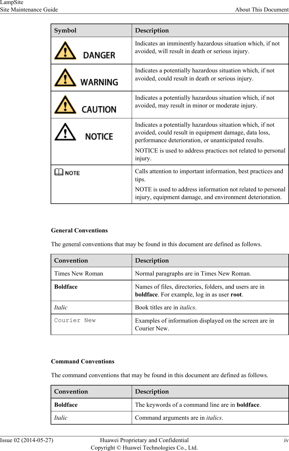
Symbol DescriptionIndicates an imminently hazardous situation which, if notavoided, will result in death or serious injury.Indicates a potentially hazardous situation which, if notavoided, could result in death or serious injury.Indicates a potentially hazardous situation which, if notavoided, may result in minor or moderate injury.Indicates a potentially hazardous situation which, if notavoided, could result in equipment damage, data loss,performance deterioration, or unanticipated results.NOTICE is used to address practices not related to personalinjury.Calls attention to important information, best practices andtips.NOTE is used to address information not related to personalinjury, equipment damage, and environment deterioration. General ConventionsThe general conventions that may be found in this document are defined as follows.Convention DescriptionTimes New Roman Normal paragraphs are in Times New Roman.Boldface Names of files, directories, folders, and users are inboldface. For example, log in as user root.Italic Book titles are in italics.Courier New Examples of information displayed on the screen are inCourier New. Command ConventionsThe command conventions that may be found in this document are defined as follows.Convention DescriptionBoldface The keywords of a command line are in boldface.Italic Command arguments are in italics.LampSiteSite Maintenance Guide About This DocumentIssue 02 (2014-05-27) Huawei Proprietary and ConfidentialCopyright © Huawei Technologies Co., Ltd.iv
Convention Description[ ] Items (keywords or arguments) in brackets [ ] are optional.{ x | y | ... } Optional items are grouped in braces and separated byvertical bars. One item is selected.[ x | y | ... ] Optional items are grouped in brackets and separated byvertical bars. One item is selected or no item is selected.{ x | y | ... }*Optional items are grouped in braces and separated byvertical bars. A minimum of one item or a maximum of allitems can be selected.[ x | y | ... ]*Optional items are grouped in brackets and separated byvertical bars. Several items or no item can be selected. GUI ConventionsThe GUI conventions that may be found in this document are defined as follows.Convention DescriptionBoldface Buttons, menus, parameters, tabs, window, and dialog titlesare in boldface. For example, click OK.>Multi-level menus are in boldface and separated by the ">"signs. For example, choose File > Create > Folder. Keyboard OperationsThe keyboard operations that may be found in this document are defined as follows.Format DescriptionKey Press the key. For example, press Enter and press Tab.Key 1+Key 2 Press the keys concurrently. For example, pressing Ctrl+Alt+A means the three keys should be pressed concurrently.Key 1, Key 2 Press the keys in turn. For example, pressing Alt, A meansthe two keys should be pressed in turn. Mouse OperationsThe mouse operations that may be found in this document are defined as follows.LampSiteSite Maintenance Guide About This DocumentIssue 02 (2014-05-27) Huawei Proprietary and ConfidentialCopyright © Huawei Technologies Co., Ltd.v
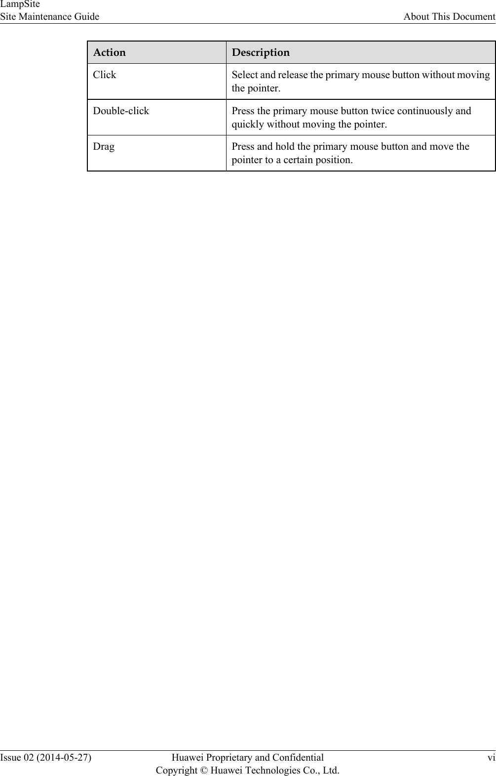
Action DescriptionClick Select and release the primary mouse button without movingthe pointer.Double-click Press the primary mouse button twice continuously andquickly without moving the pointer.Drag Press and hold the primary mouse button and move thepointer to a certain position.LampSiteSite Maintenance Guide About This DocumentIssue 02 (2014-05-27) Huawei Proprietary and ConfidentialCopyright © Huawei Technologies Co., Ltd.vi
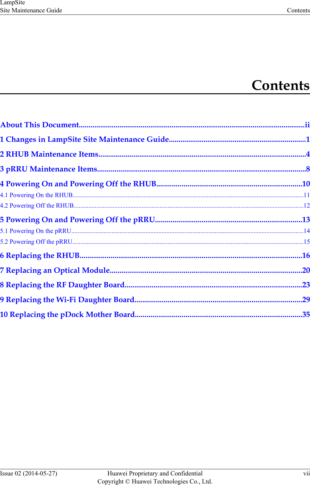
ContentsAbout This Document.....................................................................................................................ii1 Changes in LampSite Site Maintenance Guide.......................................................................12 RHUB Maintenance Items...........................................................................................................43 pRRU Maintenance Items............................................................................................................84 Powering On and Powering Off the RHUB...........................................................................104.1 Powering On the RHUB...............................................................................................................................................114.2 Powering Off the RHUB..............................................................................................................................................125 Powering On and Powering Off the pRRU............................................................................135.1 Powering On the pRRU................................................................................................................................................145.2 Powering Off the pRRU...............................................................................................................................................156 Replacing the RHUB...................................................................................................................167 Replacing an Optical Module...................................................................................................208 Replacing the RF Daughter Board............................................................................................239 Replacing the Wi-Fi Daughter Board......................................................................................2910 Replacing the pDock Mother Board......................................................................................35LampSiteSite Maintenance Guide ContentsIssue 02 (2014-05-27) Huawei Proprietary and ConfidentialCopyright © Huawei Technologies Co., Ltd.vii
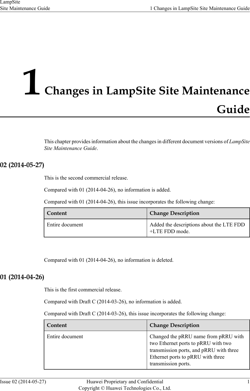
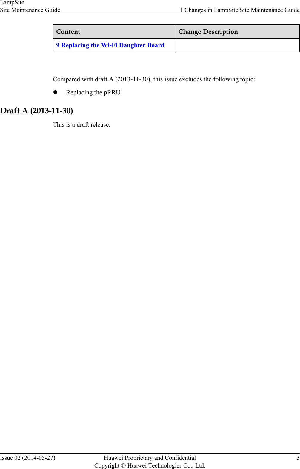
1 Changes in LampSite Site MaintenanceGuideThis chapter provides information about the changes in different document versions of LampSiteSite Maintenance Guide.02 (2014-05-27)This is the second commercial release.Compared with 01 (2014-04-26), no information is added.Compared with 01 (2014-04-26), this issue incorporates the following change:Content Change DescriptionEntire document Added the descriptions about the LTE FDD+LTE FDD mode. Compared with 01 (2014-04-26), no information is deleted.01 (2014-04-26)This is the first commercial release.Compared with Draft C (2014-03-26), no information is added.Compared with Draft C (2014-03-26), this issue incorporates the following change:Content Change DescriptionEntire document Changed the pRRU name from pRRU withtwo Ethernet ports to pRRU with twotransmission ports, and pRRU with threeEthernet ports to pRRU with threetransmission ports.LampSiteSite Maintenance Guide 1 Changes in LampSite Site Maintenance GuideIssue 02 (2014-05-27) Huawei Proprietary and ConfidentialCopyright © Huawei Technologies Co., Ltd.1
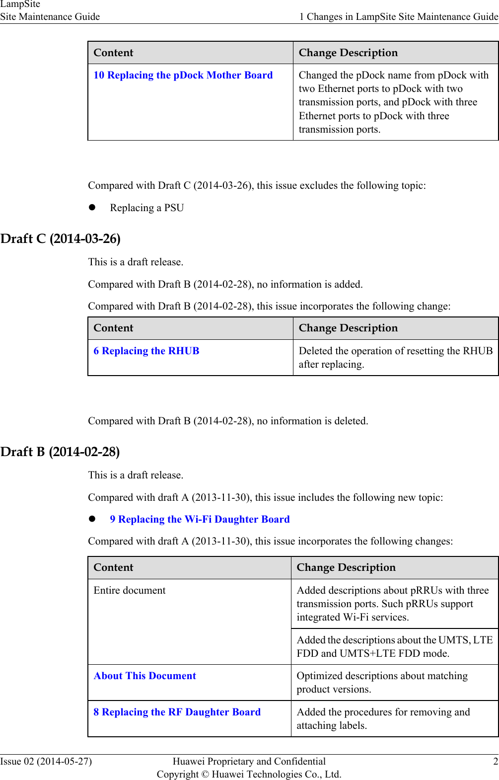
Content Change Description10 Replacing the pDock Mother Board Changed the pDock name from pDock withtwo Ethernet ports to pDock with twotransmission ports, and pDock with threeEthernet ports to pDock with threetransmission ports. Compared with Draft C (2014-03-26), this issue excludes the following topic:lReplacing a PSUDraft C (2014-03-26)This is a draft release.Compared with Draft B (2014-02-28), no information is added.Compared with Draft B (2014-02-28), this issue incorporates the following change:Content Change Description6 Replacing the RHUB Deleted the operation of resetting the RHUBafter replacing. Compared with Draft B (2014-02-28), no information is deleted.Draft B (2014-02-28)This is a draft release.Compared with draft A (2013-11-30), this issue includes the following new topic:l9 Replacing the Wi-Fi Daughter BoardCompared with draft A (2013-11-30), this issue incorporates the following changes:Content Change DescriptionEntire document Added descriptions about pRRUs with threetransmission ports. Such pRRUs supportintegrated Wi-Fi services.Added the descriptions about the UMTS, LTEFDD and UMTS+LTE FDD mode.About This Document Optimized descriptions about matchingproduct versions.8 Replacing the RF Daughter Board Added the procedures for removing andattaching labels.LampSiteSite Maintenance Guide 1 Changes in LampSite Site Maintenance GuideIssue 02 (2014-05-27) Huawei Proprietary and ConfidentialCopyright © Huawei Technologies Co., Ltd.2
Content Change Description9 Replacing the Wi-Fi Daughter Board Compared with draft A (2013-11-30), this issue excludes the following topic:lReplacing the pRRUDraft A (2013-11-30)This is a draft release.LampSiteSite Maintenance Guide 1 Changes in LampSite Site Maintenance GuideIssue 02 (2014-05-27) Huawei Proprietary and ConfidentialCopyright © Huawei Technologies Co., Ltd.3
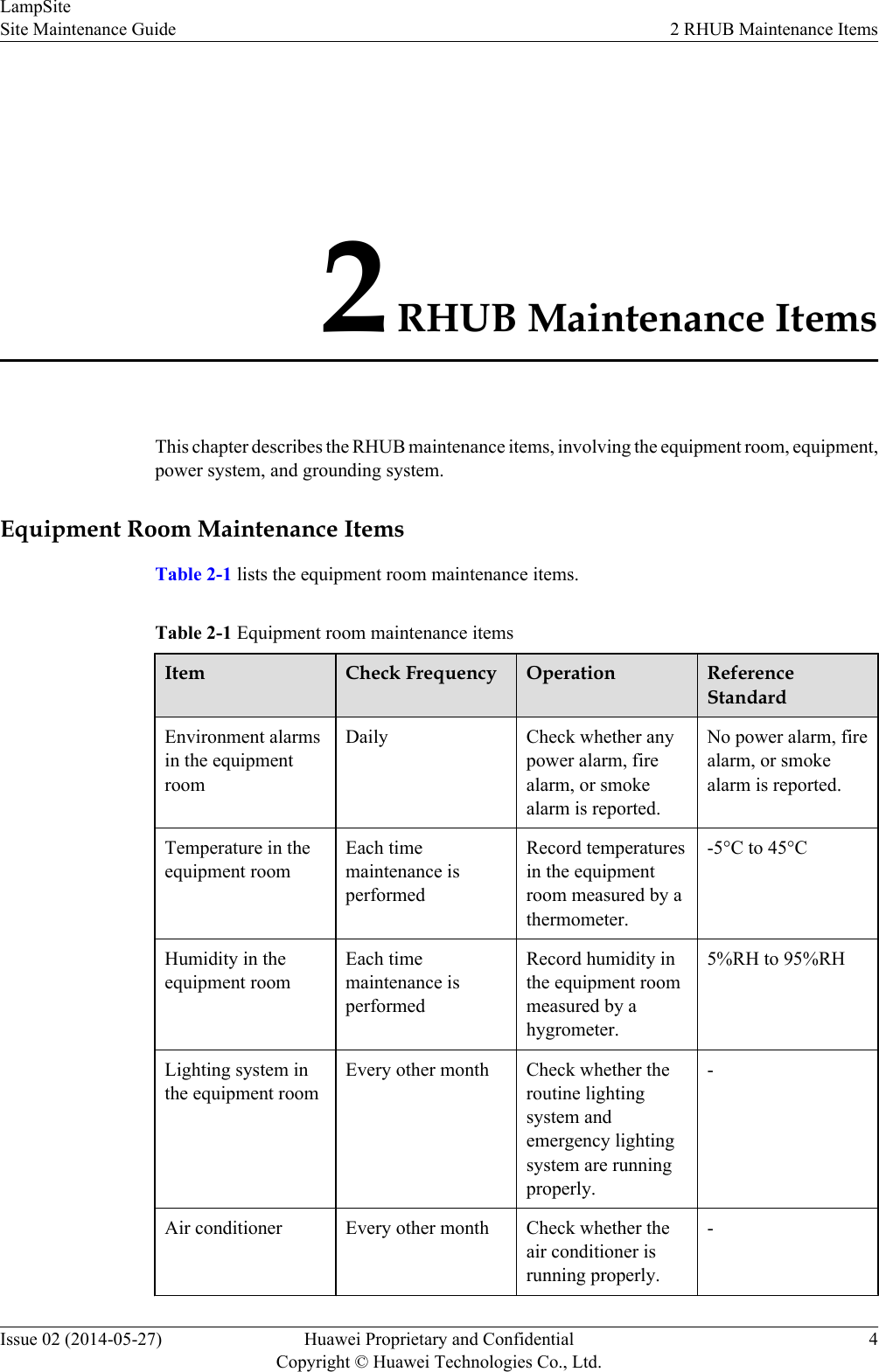
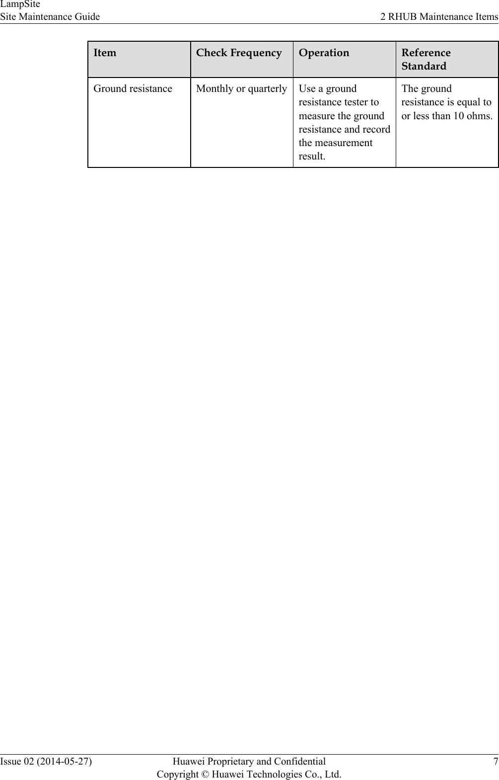
2 RHUB Maintenance ItemsThis chapter describes the RHUB maintenance items, involving the equipment room, equipment,power system, and grounding system.Equipment Room Maintenance ItemsTable 2-1 lists the equipment room maintenance items.Table 2-1 Equipment room maintenance itemsItem Check Frequency Operation ReferenceStandardEnvironment alarmsin the equipmentroomDaily Check whether anypower alarm, firealarm, or smokealarm is reported.No power alarm, firealarm, or smokealarm is reported.Temperature in theequipment roomEach timemaintenance isperformedRecord temperaturesin the equipmentroom measured by athermometer.-5°C to 45°CHumidity in theequipment roomEach timemaintenance isperformedRecord humidity inthe equipment roommeasured by ahygrometer.5%RH to 95%RHLighting system inthe equipment roomEvery other month Check whether theroutine lightingsystem andemergency lightingsystem are runningproperly.-Air conditioner Every other month Check whether theair conditioner isrunning properly.-LampSiteSite Maintenance Guide 2 RHUB Maintenance ItemsIssue 02 (2014-05-27) Huawei Proprietary and ConfidentialCopyright © Huawei Technologies Co., Ltd.4
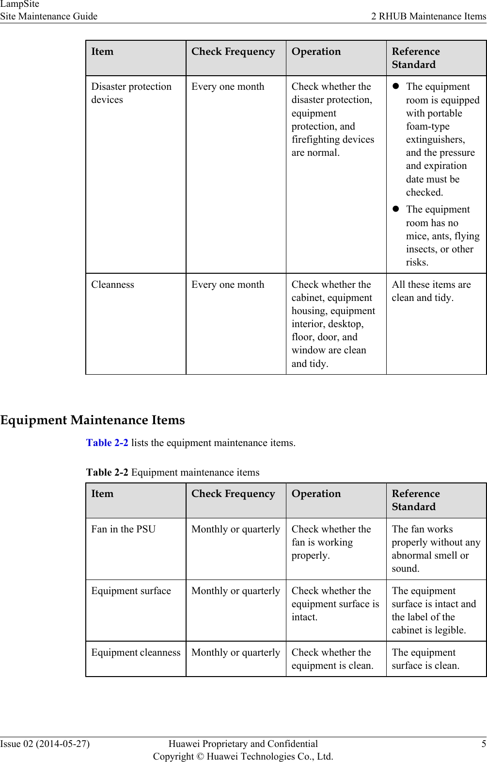
Item Check Frequency Operation ReferenceStandardDisaster protectiondevicesEvery one month Check whether thedisaster protection,equipmentprotection, andfirefighting devicesare normal.lThe equipmentroom is equippedwith portablefoam-typeextinguishers,and the pressureand expirationdate must bechecked.lThe equipmentroom has nomice, ants, flyinginsects, or otherrisks.Cleanness Every one month Check whether thecabinet, equipmenthousing, equipmentinterior, desktop,floor, door, andwindow are cleanand tidy.All these items areclean and tidy. Equipment Maintenance ItemsTable 2-2 lists the equipment maintenance items.Table 2-2 Equipment maintenance itemsItem Check Frequency Operation ReferenceStandardFan in the PSU Monthly or quarterly Check whether thefan is workingproperly.The fan worksproperly without anyabnormal smell orsound.Equipment surface Monthly or quarterly Check whether theequipment surface isintact.The equipmentsurface is intact andthe label of thecabinet is legible.Equipment cleanness Monthly or quarterly Check whether theequipment is clean.The equipmentsurface is clean.LampSiteSite Maintenance Guide 2 RHUB Maintenance ItemsIssue 02 (2014-05-27) Huawei Proprietary and ConfidentialCopyright © Huawei Technologies Co., Ltd.5
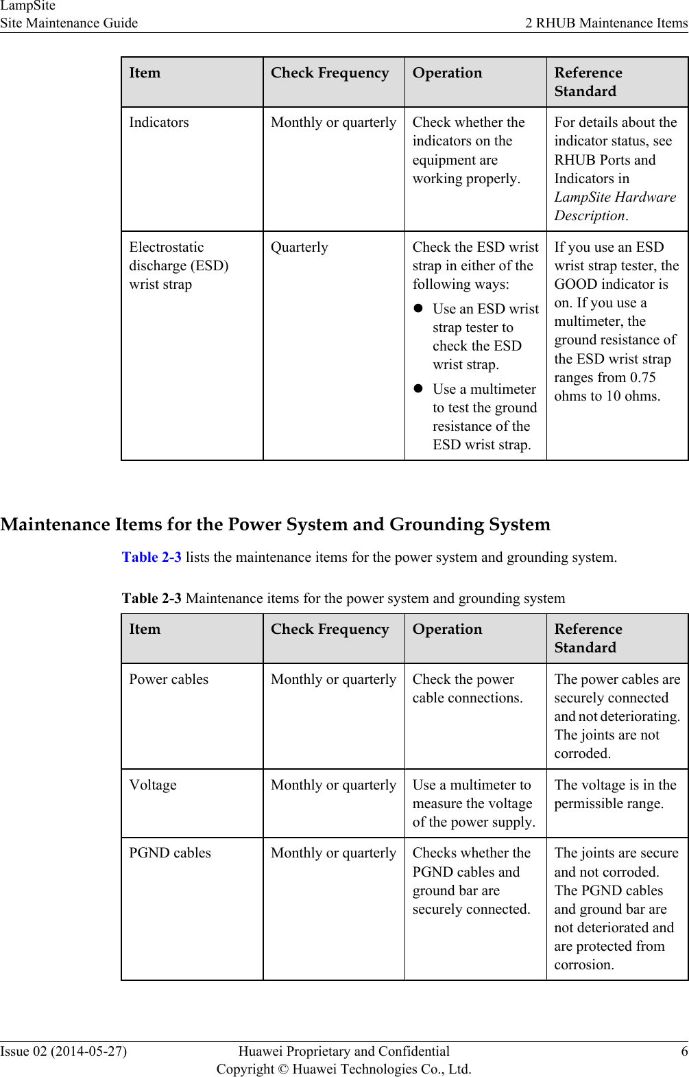
Item Check Frequency Operation ReferenceStandardIndicators Monthly or quarterly Check whether theindicators on theequipment areworking properly.For details about theindicator status, seeRHUB Ports andIndicators inLampSite HardwareDescription.Electrostaticdischarge (ESD)wrist strapQuarterly Check the ESD wriststrap in either of thefollowing ways:lUse an ESD wriststrap tester tocheck the ESDwrist strap.lUse a multimeterto test the groundresistance of theESD wrist strap.If you use an ESDwrist strap tester, theGOOD indicator ison. If you use amultimeter, theground resistance ofthe ESD wrist strapranges from 0.75ohms to 10 ohms. Maintenance Items for the Power System and Grounding SystemTable 2-3 lists the maintenance items for the power system and grounding system.Table 2-3 Maintenance items for the power system and grounding systemItem Check Frequency Operation ReferenceStandardPower cables Monthly or quarterly Check the powercable connections.The power cables aresecurely connectedand not deteriorating.The joints are notcorroded.Voltage Monthly or quarterly Use a multimeter tomeasure the voltageof the power supply.The voltage is in thepermissible range.PGND cables Monthly or quarterly Checks whether thePGND cables andground bar aresecurely connected.The joints are secureand not corroded.The PGND cablesand ground bar arenot deteriorated andare protected fromcorrosion.LampSiteSite Maintenance Guide 2 RHUB Maintenance ItemsIssue 02 (2014-05-27) Huawei Proprietary and ConfidentialCopyright © Huawei Technologies Co., Ltd.6
Item Check Frequency Operation ReferenceStandardGround resistance Monthly or quarterly Use a groundresistance tester tomeasure the groundresistance and recordthe measurementresult.The groundresistance is equal toor less than 10 ohms.LampSiteSite Maintenance Guide 2 RHUB Maintenance ItemsIssue 02 (2014-05-27) Huawei Proprietary and ConfidentialCopyright © Huawei Technologies Co., Ltd.7
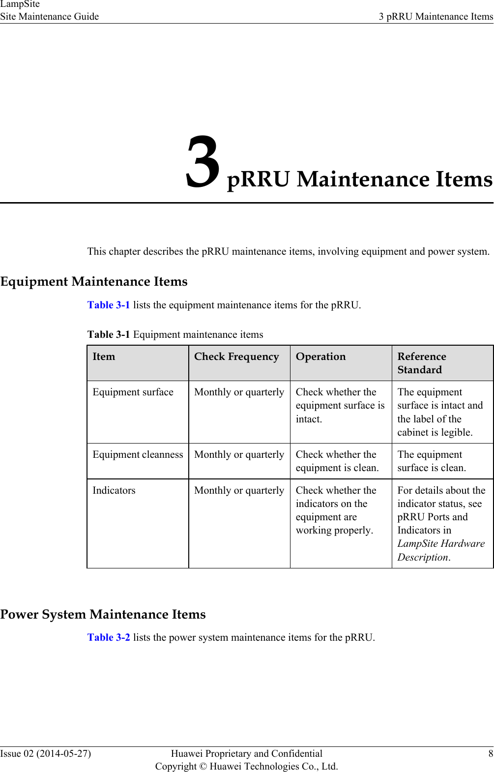
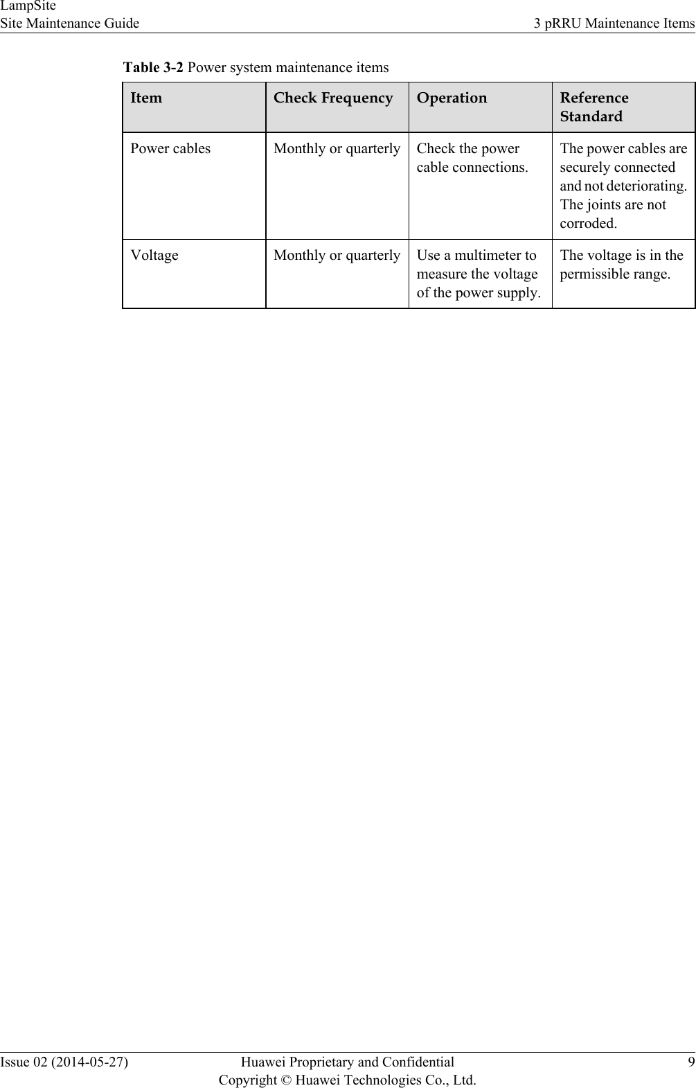
3 pRRU Maintenance ItemsThis chapter describes the pRRU maintenance items, involving equipment and power system.Equipment Maintenance ItemsTable 3-1 lists the equipment maintenance items for the pRRU.Table 3-1 Equipment maintenance itemsItem Check Frequency Operation ReferenceStandardEquipment surface Monthly or quarterly Check whether theequipment surface isintact.The equipmentsurface is intact andthe label of thecabinet is legible.Equipment cleanness Monthly or quarterly Check whether theequipment is clean.The equipmentsurface is clean.Indicators Monthly or quarterly Check whether theindicators on theequipment areworking properly.For details about theindicator status, seepRRU Ports andIndicators inLampSite HardwareDescription. Power System Maintenance ItemsTable 3-2 lists the power system maintenance items for the pRRU.LampSiteSite Maintenance Guide 3 pRRU Maintenance ItemsIssue 02 (2014-05-27) Huawei Proprietary and ConfidentialCopyright © Huawei Technologies Co., Ltd.8
Table 3-2 Power system maintenance itemsItem Check Frequency Operation ReferenceStandardPower cables Monthly or quarterly Check the powercable connections.The power cables aresecurely connectedand not deteriorating.The joints are notcorroded.Voltage Monthly or quarterly Use a multimeter tomeasure the voltageof the power supply.The voltage is in thepermissible range.LampSiteSite Maintenance Guide 3 pRRU Maintenance ItemsIssue 02 (2014-05-27) Huawei Proprietary and ConfidentialCopyright © Huawei Technologies Co., Ltd.9
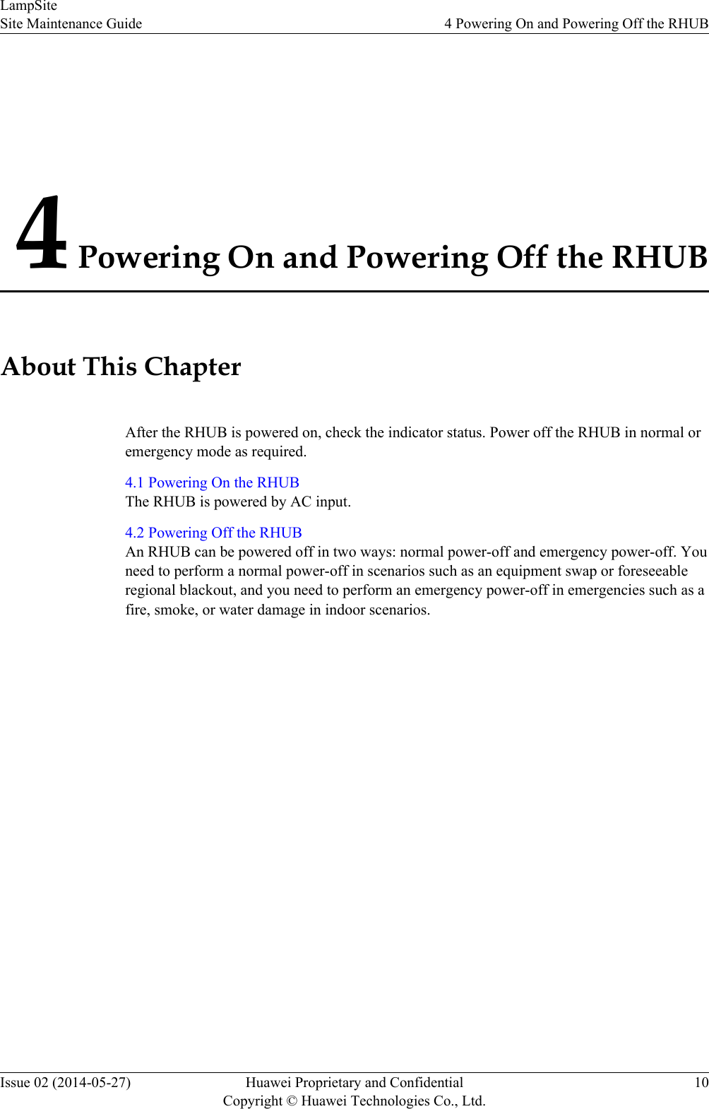
4 Powering On and Powering Off the RHUBAbout This ChapterAfter the RHUB is powered on, check the indicator status. Power off the RHUB in normal oremergency mode as required.4.1 Powering On the RHUBThe RHUB is powered by AC input.4.2 Powering Off the RHUBAn RHUB can be powered off in two ways: normal power-off and emergency power-off. Youneed to perform a normal power-off in scenarios such as an equipment swap or foreseeableregional blackout, and you need to perform an emergency power-off in emergencies such as afire, smoke, or water damage in indoor scenarios.LampSiteSite Maintenance Guide 4 Powering On and Powering Off the RHUBIssue 02 (2014-05-27) Huawei Proprietary and ConfidentialCopyright © Huawei Technologies Co., Ltd.10
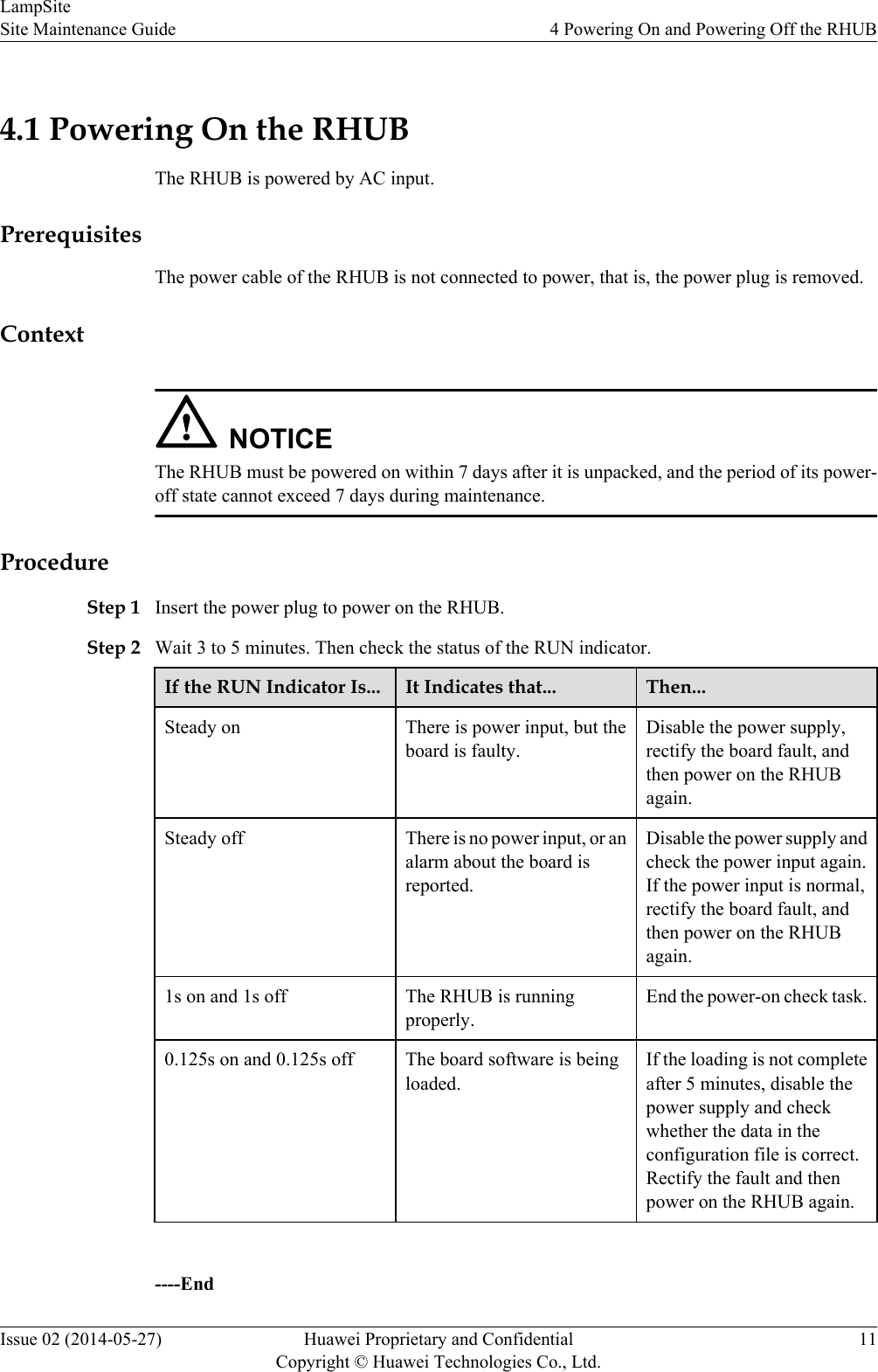
4.1 Powering On the RHUBThe RHUB is powered by AC input.PrerequisitesThe power cable of the RHUB is not connected to power, that is, the power plug is removed.ContextNOTICEThe RHUB must be powered on within 7 days after it is unpacked, and the period of its power-off state cannot exceed 7 days during maintenance.ProcedureStep 1 Insert the power plug to power on the RHUB.Step 2 Wait 3 to 5 minutes. Then check the status of the RUN indicator.If the RUN Indicator Is... It Indicates that... Then...Steady on There is power input, but theboard is faulty.Disable the power supply,rectify the board fault, andthen power on the RHUBagain.Steady off There is no power input, or analarm about the board isreported.Disable the power supply andcheck the power input again.If the power input is normal,rectify the board fault, andthen power on the RHUBagain.1s on and 1s off The RHUB is runningproperly.End the power-on check task.0.125s on and 0.125s off The board software is beingloaded.If the loading is not completeafter 5 minutes, disable thepower supply and checkwhether the data in theconfiguration file is correct.Rectify the fault and thenpower on the RHUB again. ----EndLampSiteSite Maintenance Guide 4 Powering On and Powering Off the RHUBIssue 02 (2014-05-27) Huawei Proprietary and ConfidentialCopyright © Huawei Technologies Co., Ltd.11
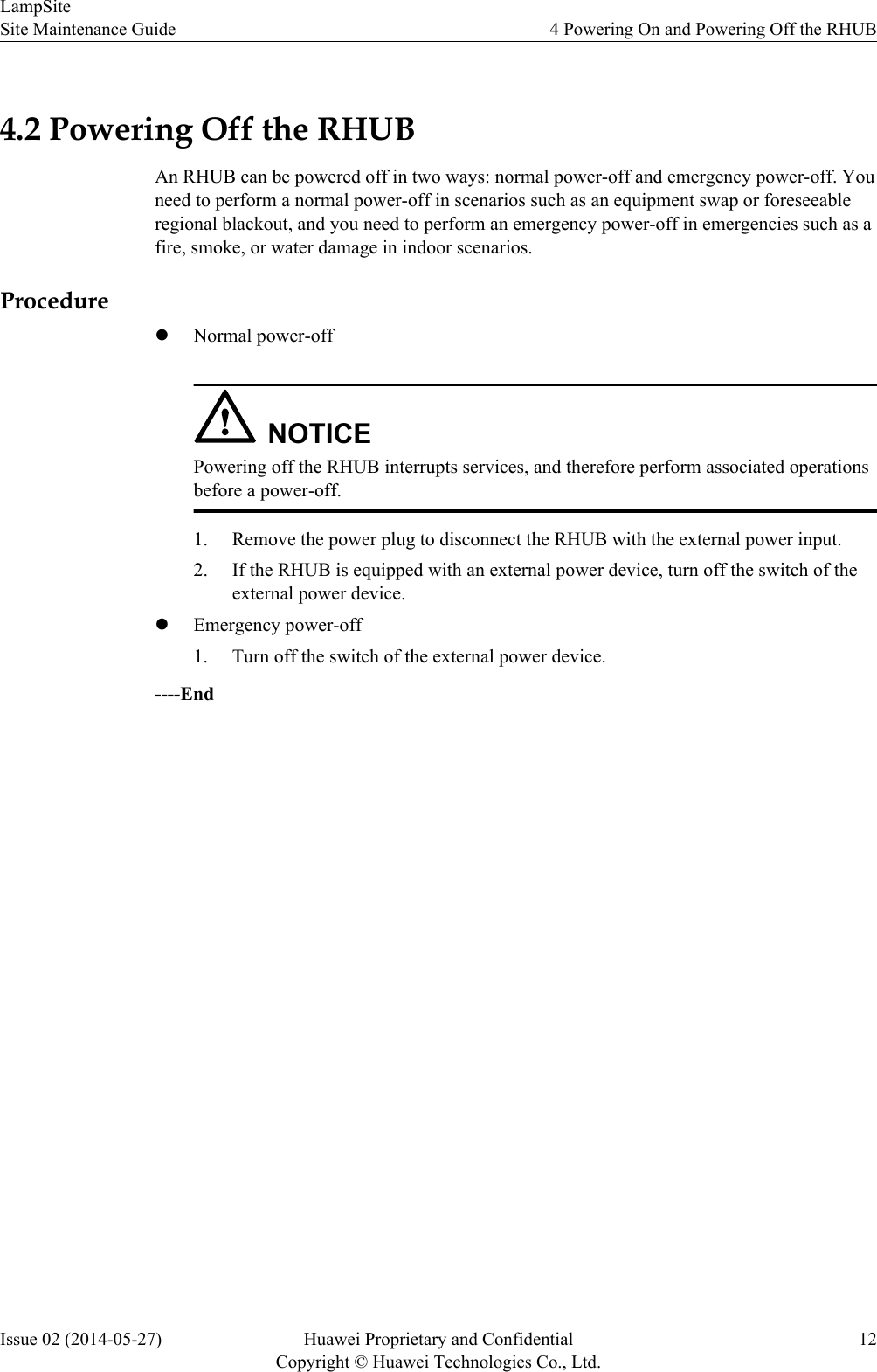
4.2 Powering Off the RHUBAn RHUB can be powered off in two ways: normal power-off and emergency power-off. Youneed to perform a normal power-off in scenarios such as an equipment swap or foreseeableregional blackout, and you need to perform an emergency power-off in emergencies such as afire, smoke, or water damage in indoor scenarios.ProcedurelNormal power-offNOTICEPowering off the RHUB interrupts services, and therefore perform associated operationsbefore a power-off.1. Remove the power plug to disconnect the RHUB with the external power input.2. If the RHUB is equipped with an external power device, turn off the switch of theexternal power device.lEmergency power-off1. Turn off the switch of the external power device.----EndLampSiteSite Maintenance Guide 4 Powering On and Powering Off the RHUBIssue 02 (2014-05-27) Huawei Proprietary and ConfidentialCopyright © Huawei Technologies Co., Ltd.12
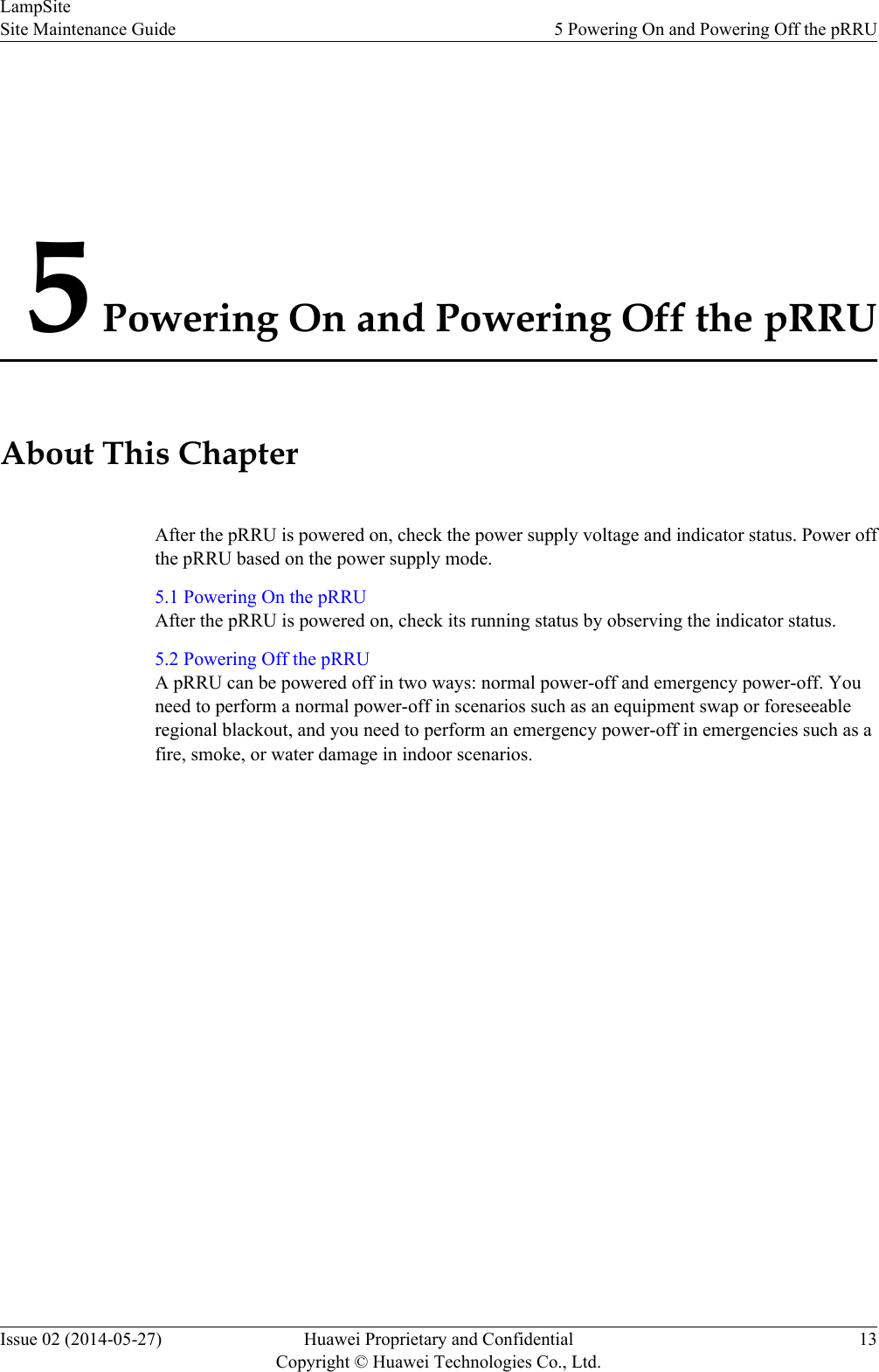
5 Powering On and Powering Off the pRRUAbout This ChapterAfter the pRRU is powered on, check the power supply voltage and indicator status. Power offthe pRRU based on the power supply mode.5.1 Powering On the pRRUAfter the pRRU is powered on, check its running status by observing the indicator status.5.2 Powering Off the pRRUA pRRU can be powered off in two ways: normal power-off and emergency power-off. Youneed to perform a normal power-off in scenarios such as an equipment swap or foreseeableregional blackout, and you need to perform an emergency power-off in emergencies such as afire, smoke, or water damage in indoor scenarios.LampSiteSite Maintenance Guide 5 Powering On and Powering Off the pRRUIssue 02 (2014-05-27) Huawei Proprietary and ConfidentialCopyright © Huawei Technologies Co., Ltd.13
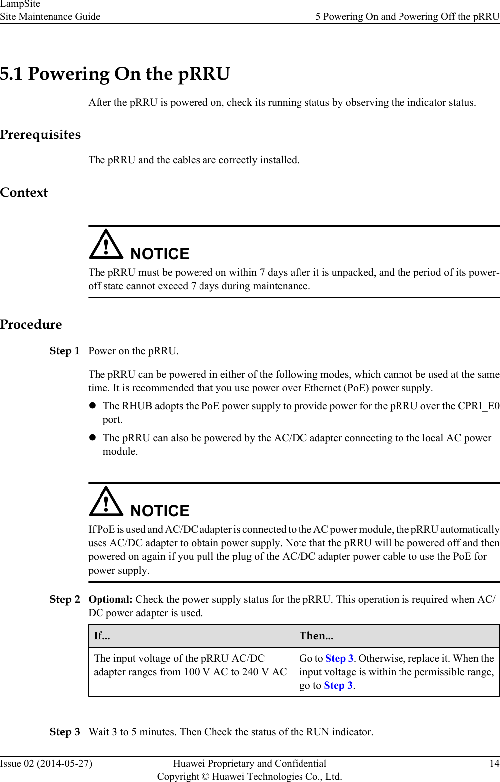
5.1 Powering On the pRRUAfter the pRRU is powered on, check its running status by observing the indicator status.PrerequisitesThe pRRU and the cables are correctly installed.ContextNOTICEThe pRRU must be powered on within 7 days after it is unpacked, and the period of its power-off state cannot exceed 7 days during maintenance.ProcedureStep 1 Power on the pRRU.The pRRU can be powered in either of the following modes, which cannot be used at the sametime. It is recommended that you use power over Ethernet (PoE) power supply.lThe RHUB adopts the PoE power supply to provide power for the pRRU over the CPRI_E0port.lThe pRRU can also be powered by the AC/DC adapter connecting to the local AC powermodule.NOTICEIf PoE is used and AC/DC adapter is connected to the AC power module, the pRRU automaticallyuses AC/DC adapter to obtain power supply. Note that the pRRU will be powered off and thenpowered on again if you pull the plug of the AC/DC adapter power cable to use the PoE forpower supply.Step 2 Optional: Check the power supply status for the pRRU. This operation is required when AC/DC power adapter is used.If... Then...The input voltage of the pRRU AC/DCadapter ranges from 100 V AC to 240 V ACGo to Step 3. Otherwise, replace it. When theinput voltage is within the permissible range,go to Step 3. Step 3 Wait 3 to 5 minutes. Then Check the status of the RUN indicator.LampSiteSite Maintenance Guide 5 Powering On and Powering Off the pRRUIssue 02 (2014-05-27) Huawei Proprietary and ConfidentialCopyright © Huawei Technologies Co., Ltd.14
If the RUN Indicator Is... It Indicates that... Then...Steady on There is power input, but theboard is faulty.Disable the power supply,rectify the board fault, andthen power on the pRRUagain.Steady off There is no power input. Disable the power supply andcheck the power input again.On for 1s and off for 1s The pRRU is runningproperly.End the power-on check task.On for 0.125s and off for0.125sThe board software is beingloaded.If the loading is not completeafter 5 minutes, disable thepower supply. Checkwhether the data in theconfiguration file is correct.Rectify the fault and thenpower on the pRRU again. ----End5.2 Powering Off the pRRUA pRRU can be powered off in two ways: normal power-off and emergency power-off. Youneed to perform a normal power-off in scenarios such as an equipment swap or foreseeableregional blackout, and you need to perform an emergency power-off in emergencies such as afire, smoke, or water damage in indoor scenarios.ProcedurelNormal power-offNOTICEPowering off the pRRU interrupts services, and therefore perform associated operationsbefore a power-off.–If the pRRU is powered in PoE mode, remove the Ethernet cable.–If the pRRU is powered by an AC/DC adapter, disconnect the power cable of the AC/DC adapter.lEmergency power-off1. Turn off the switch of the external power device.----EndLampSiteSite Maintenance Guide 5 Powering On and Powering Off the pRRUIssue 02 (2014-05-27) Huawei Proprietary and ConfidentialCopyright © Huawei Technologies Co., Ltd.15
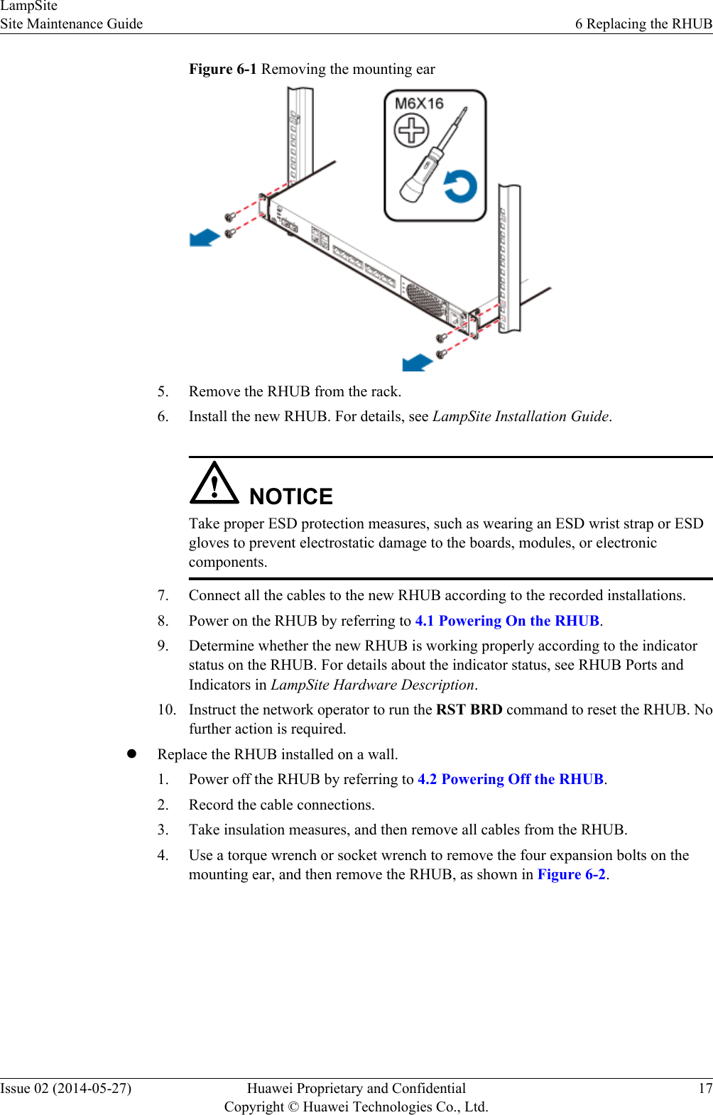
6 Replacing the RHUBThe RHUB is an indoor convergence unit. It converges multiple pRRUs to the BBU. Replacingthe RHUB interrupts services carried on the serving cell.PrerequisiteslA new RHUB is available.lThe labels and connections of the cables connected to the RHUB are recorded.lThe following tools are available: a Phillips screwdriver, an ESD wrist strap, and a rubbermallet.ContextIt takes about 10 minutes to replace the RHUB.ProcedurelReplace the RHUB installed on a 19-inch rack, in a 19-inch cabinet or in a 19-Inch Shelf.NOTEThe procedures for replacing the RHUB installed on a 19-inch rack are the same for replacing theRHUB installed in a 19-inch cabinet or in a 19-Inch Shelf. The following uses the RHUB installedon a 19-inch rack as an example.1. Power off the RHUB by referring to 4.2 Powering Off the RHUB.2. Record the cable connections.3. Take insulation measures, and then remove all cables from the RHUB.4. Use a torque screwdriver or Phillips screwdriver to remove the four screws on themounting ear of the RHUB, as shown in Figure 6-1.LampSiteSite Maintenance Guide 6 Replacing the RHUBIssue 02 (2014-05-27) Huawei Proprietary and ConfidentialCopyright © Huawei Technologies Co., Ltd.16
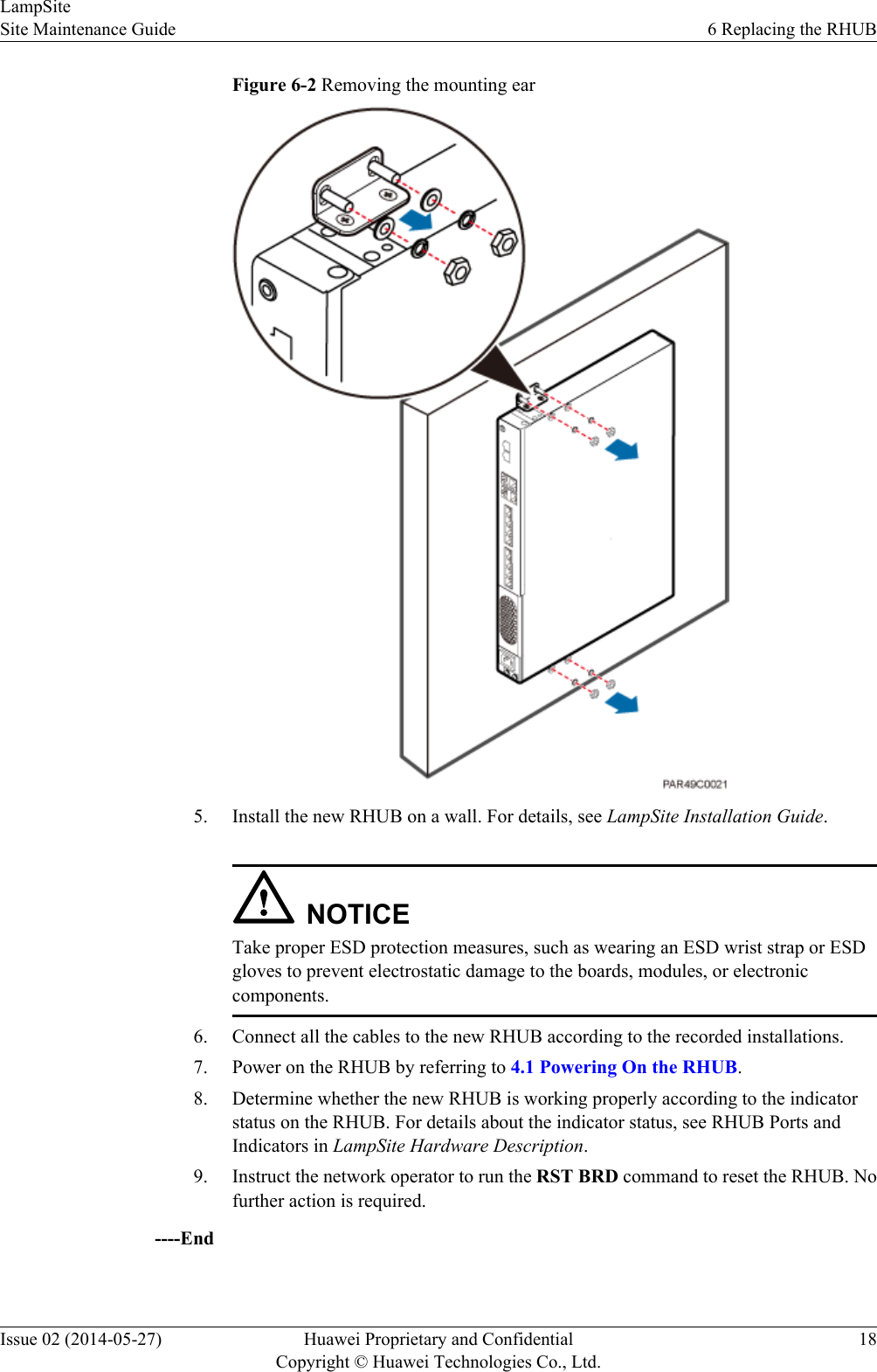
Figure 6-1 Removing the mounting ear5. Remove the RHUB from the rack.6. Install the new RHUB. For details, see LampSite Installation Guide.NOTICETake proper ESD protection measures, such as wearing an ESD wrist strap or ESDgloves to prevent electrostatic damage to the boards, modules, or electroniccomponents.7. Connect all the cables to the new RHUB according to the recorded installations.8. Power on the RHUB by referring to 4.1 Powering On the RHUB.9. Determine whether the new RHUB is working properly according to the indicatorstatus on the RHUB. For details about the indicator status, see RHUB Ports andIndicators in LampSite Hardware Description.10. Instruct the network operator to run the RST BRD command to reset the RHUB. Nofurther action is required.lReplace the RHUB installed on a wall.1. Power off the RHUB by referring to 4.2 Powering Off the RHUB.2. Record the cable connections.3. Take insulation measures, and then remove all cables from the RHUB.4. Use a torque wrench or socket wrench to remove the four expansion bolts on themounting ear, and then remove the RHUB, as shown in Figure 6-2.LampSiteSite Maintenance Guide 6 Replacing the RHUBIssue 02 (2014-05-27) Huawei Proprietary and ConfidentialCopyright © Huawei Technologies Co., Ltd.17
Figure 6-2 Removing the mounting ear5. Install the new RHUB on a wall. For details, see LampSite Installation Guide.NOTICETake proper ESD protection measures, such as wearing an ESD wrist strap or ESDgloves to prevent electrostatic damage to the boards, modules, or electroniccomponents.6. Connect all the cables to the new RHUB according to the recorded installations.7. Power on the RHUB by referring to 4.1 Powering On the RHUB.8. Determine whether the new RHUB is working properly according to the indicatorstatus on the RHUB. For details about the indicator status, see RHUB Ports andIndicators in LampSite Hardware Description.9. Instruct the network operator to run the RST BRD command to reset the RHUB. Nofurther action is required.----EndLampSiteSite Maintenance Guide 6 Replacing the RHUBIssue 02 (2014-05-27) Huawei Proprietary and ConfidentialCopyright © Huawei Technologies Co., Ltd.18
Follow-up ProcedurelPlace the replaced RHUB into an ESD box or bag. Then, place the ESD box or bag into afoam-padded carton or the packing box of the new optical module.lRecord the information about the faulty component in the fault card.lContact the local Huawei office to deal with the faulty component.LampSiteSite Maintenance Guide 6 Replacing the RHUBIssue 02 (2014-05-27) Huawei Proprietary and ConfidentialCopyright © Huawei Technologies Co., Ltd.19
7 Replacing an Optical ModuleAn optical module provides a port for opto-electronic conversion. This enables the transmissionbetween the RHUB and BBU through the optical fiber. Replacing the optical module requiresremoving the optical fibers. This interrupts all the services.PrerequisiteslThe number and type of faulty optical modules are confirmed, and new optical modulesare available.lThe new optical modules to be installed must match CPRI rates.lThe position for installing an optical module and the cable connection are recorded.lThe following tools and materials are available: an ESD wrist strap or ESD gloves, and anESD box or bag.ContextlThe optical modules are connected to the CPRI0 and CPRI1 ports on the RHUB panel.lAn optical module or CPRI fiber optic cable cannot be inserted into or removed from thisCPRI port when the power supply is connected.lReplacing an optical module involves removing an optical fiber and the faulty opticalmodule, installing a new optical module, connecting the optical fiber to the optical module,and recovering the links. The operation takes about 10 minutes.NOTICETake proper ESD protection measures, such as wearing an ESD wrist strap or ESD gloves toprevent electrostatic damage to the boards, modules, or electronic components.ProcedureStep 1 Wear ESD gloves.Step 2 Record the optical module and fiber connections.Step 3 Power off the RHUB according to the instructions in 4.2 Powering Off the RHUB.LampSiteSite Maintenance Guide 7 Replacing an Optical ModuleIssue 02 (2014-05-27) Huawei Proprietary and ConfidentialCopyright © Huawei Technologies Co., Ltd.20
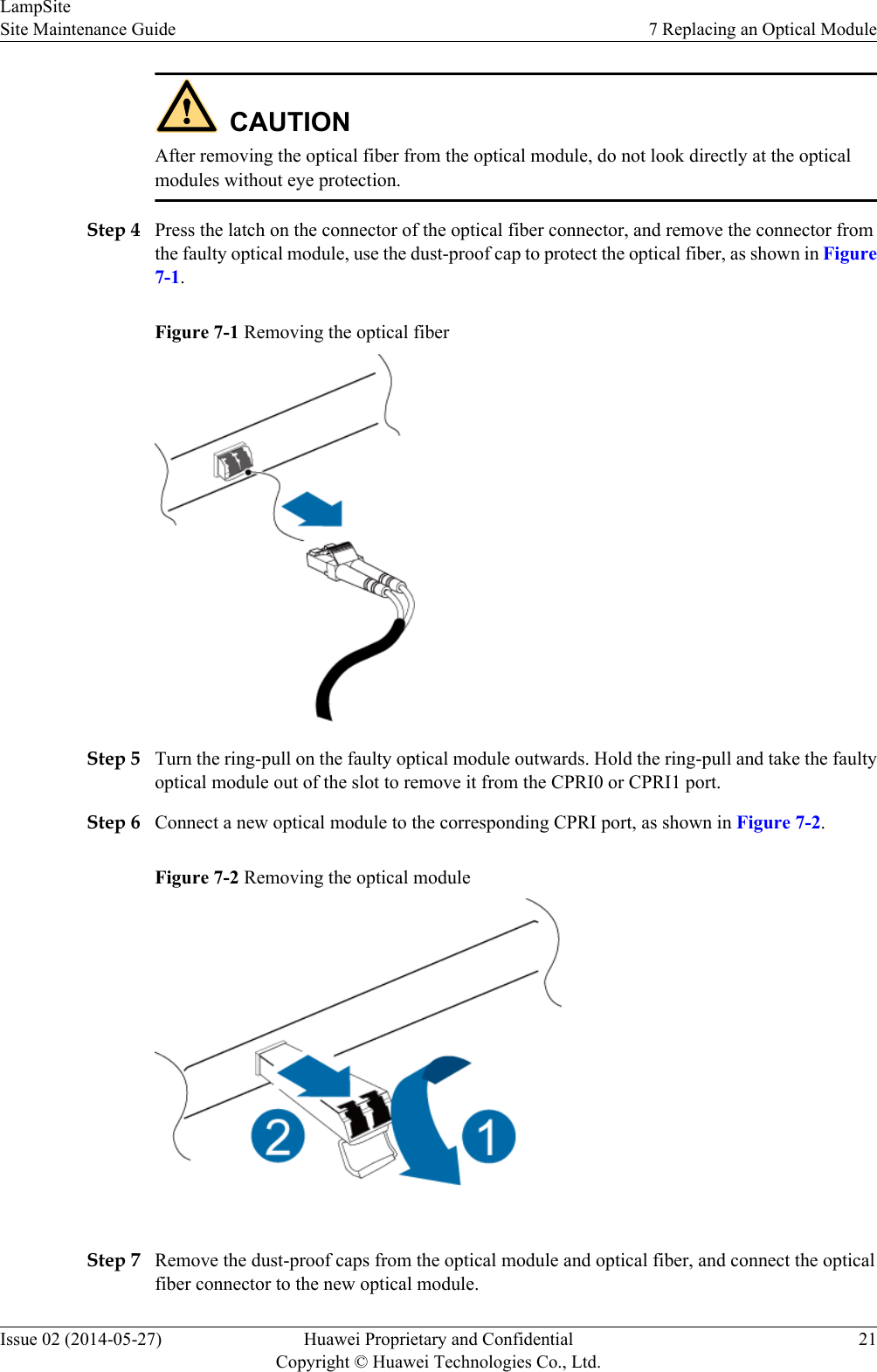
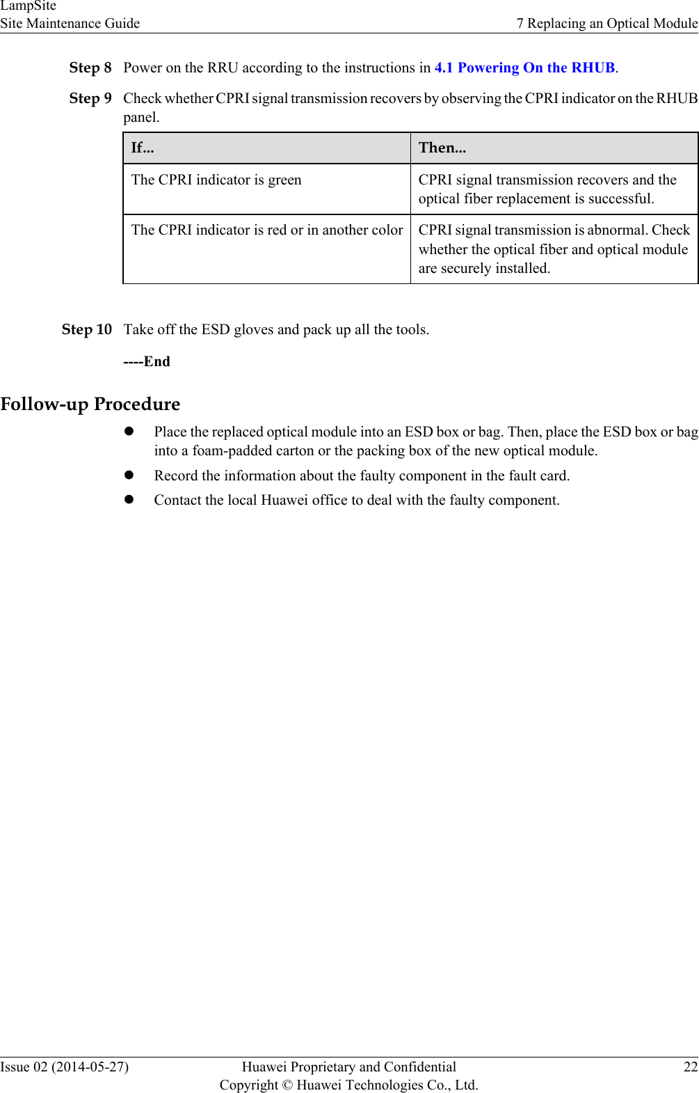
CAUTIONAfter removing the optical fiber from the optical module, do not look directly at the opticalmodules without eye protection.Step 4 Press the latch on the connector of the optical fiber connector, and remove the connector fromthe faulty optical module, use the dust-proof cap to protect the optical fiber, as shown in Figure7-1.Figure 7-1 Removing the optical fiberStep 5 Turn the ring-pull on the faulty optical module outwards. Hold the ring-pull and take the faultyoptical module out of the slot to remove it from the CPRI0 or CPRI1 port.Step 6 Connect a new optical module to the corresponding CPRI port, as shown in Figure 7-2.Figure 7-2 Removing the optical moduleStep 7 Remove the dust-proof caps from the optical module and optical fiber, and connect the opticalfiber connector to the new optical module.LampSiteSite Maintenance Guide 7 Replacing an Optical ModuleIssue 02 (2014-05-27) Huawei Proprietary and ConfidentialCopyright © Huawei Technologies Co., Ltd.21
Step 8 Power on the RRU according to the instructions in 4.1 Powering On the RHUB.Step 9 Check whether CPRI signal transmission recovers by observing the CPRI indicator on the RHUBpanel.If... Then...The CPRI indicator is green CPRI signal transmission recovers and theoptical fiber replacement is successful.The CPRI indicator is red or in another color CPRI signal transmission is abnormal. Checkwhether the optical fiber and optical moduleare securely installed. Step 10 Take off the ESD gloves and pack up all the tools.----EndFollow-up ProcedurelPlace the replaced optical module into an ESD box or bag. Then, place the ESD box or baginto a foam-padded carton or the packing box of the new optical module.lRecord the information about the faulty component in the fault card.lContact the local Huawei office to deal with the faulty component.LampSiteSite Maintenance Guide 7 Replacing an Optical ModuleIssue 02 (2014-05-27) Huawei Proprietary and ConfidentialCopyright © Huawei Technologies Co., Ltd.22
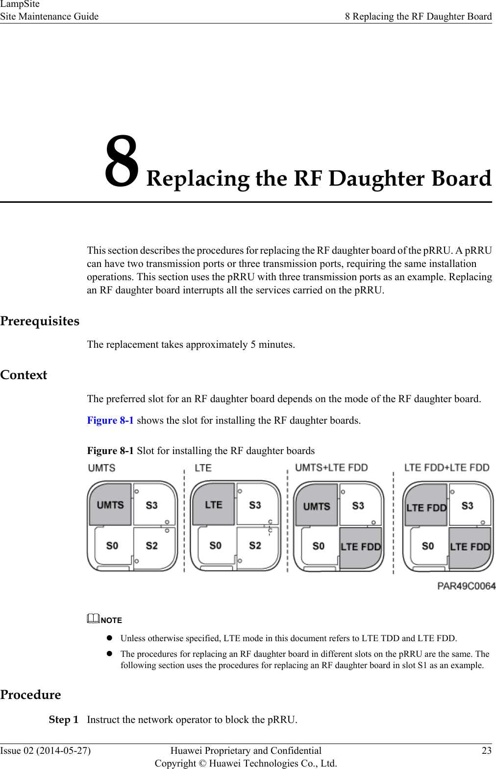
8 Replacing the RF Daughter BoardThis section describes the procedures for replacing the RF daughter board of the pRRU. A pRRUcan have two transmission ports or three transmission ports, requiring the same installationoperations. This section uses the pRRU with three transmission ports as an example. Replacingan RF daughter board interrupts all the services carried on the pRRU.PrerequisitesThe replacement takes approximately 5 minutes.ContextThe preferred slot for an RF daughter board depends on the mode of the RF daughter board.Figure 8-1 shows the slot for installing the RF daughter boards.Figure 8-1 Slot for installing the RF daughter boardsNOTElUnless otherwise specified, LTE mode in this document refers to LTE TDD and LTE FDD.lThe procedures for replacing an RF daughter board in different slots on the pRRU are the same. Thefollowing section uses the procedures for replacing an RF daughter board in slot S1 as an example.ProcedureStep 1 Instruct the network operator to block the pRRU.LampSiteSite Maintenance Guide 8 Replacing the RF Daughter BoardIssue 02 (2014-05-27) Huawei Proprietary and ConfidentialCopyright © Huawei Technologies Co., Ltd.23
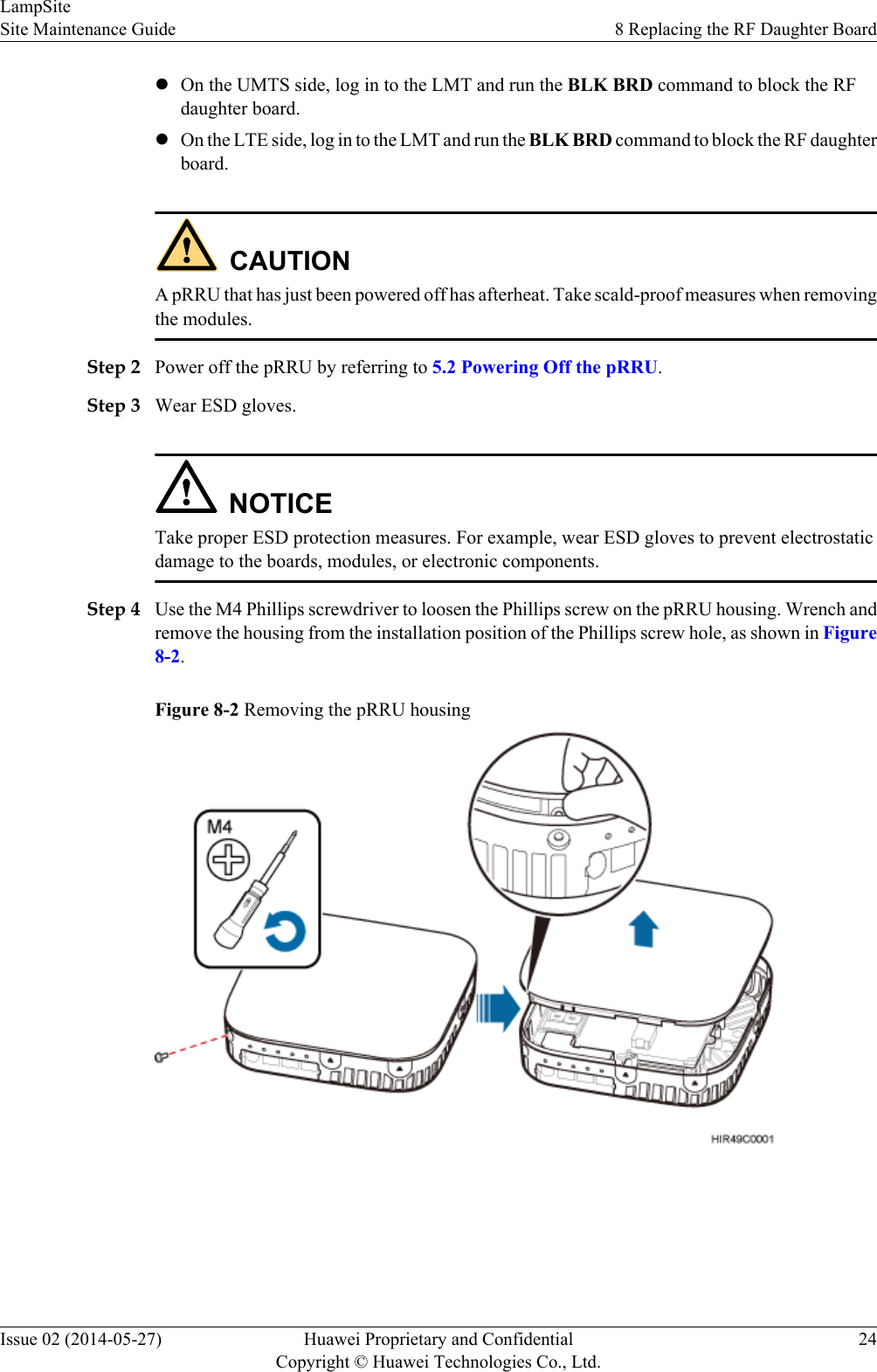
lOn the UMTS side, log in to the LMT and run the BLK BRD command to block the RFdaughter board.lOn the LTE side, log in to the LMT and run the BLK BRD command to block the RF daughterboard.CAUTIONA pRRU that has just been powered off has afterheat. Take scald-proof measures when removingthe modules.Step 2 Power off the pRRU by referring to 5.2 Powering Off the pRRU.Step 3 Wear ESD gloves.NOTICETake proper ESD protection measures. For example, wear ESD gloves to prevent electrostaticdamage to the boards, modules, or electronic components.Step 4 Use the M4 Phillips screwdriver to loosen the Phillips screw on the pRRU housing. Wrench andremove the housing from the installation position of the Phillips screw hole, as shown in Figure8-2.Figure 8-2 Removing the pRRU housingLampSiteSite Maintenance Guide 8 Replacing the RF Daughter BoardIssue 02 (2014-05-27) Huawei Proprietary and ConfidentialCopyright © Huawei Technologies Co., Ltd.24
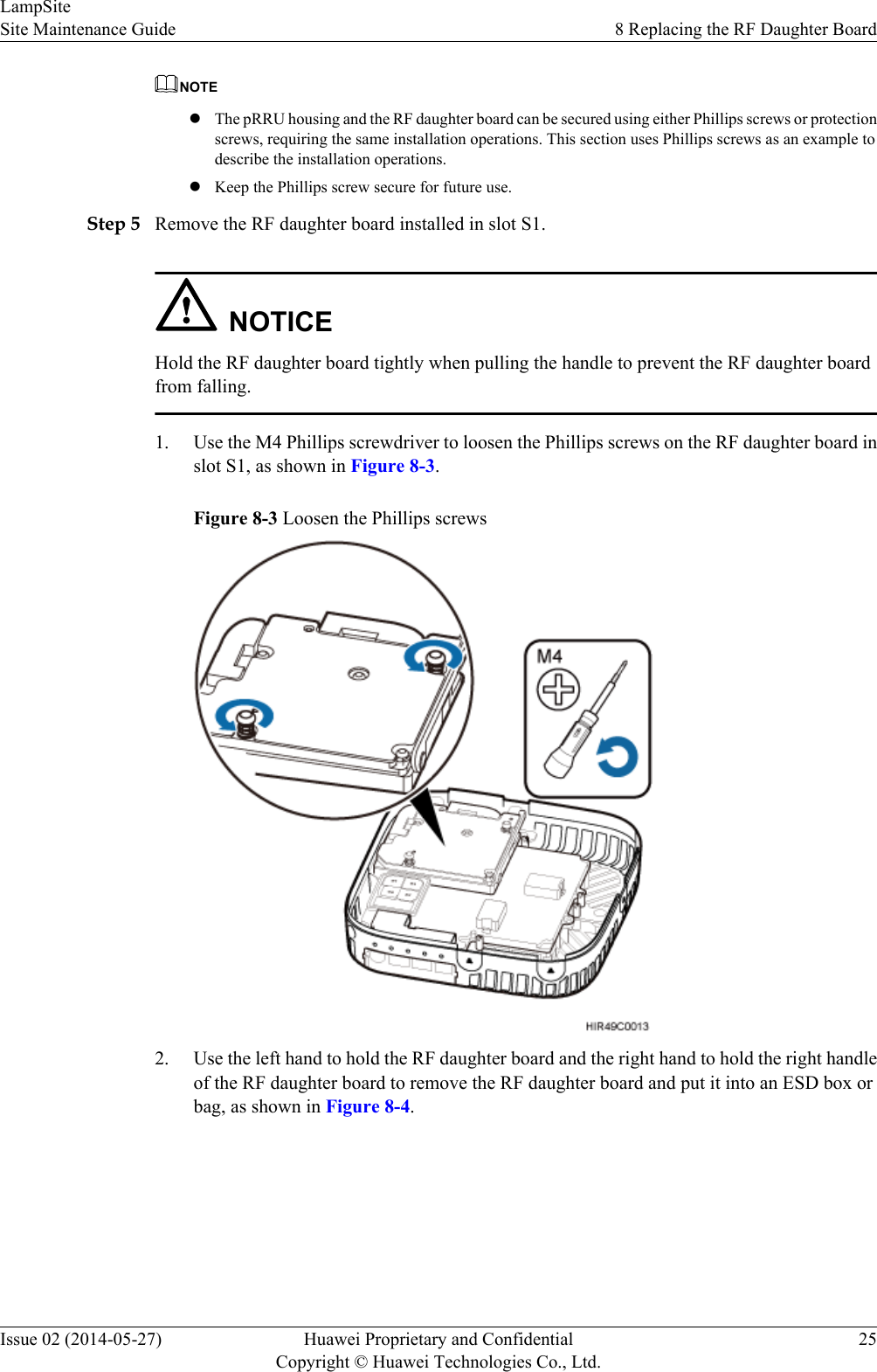
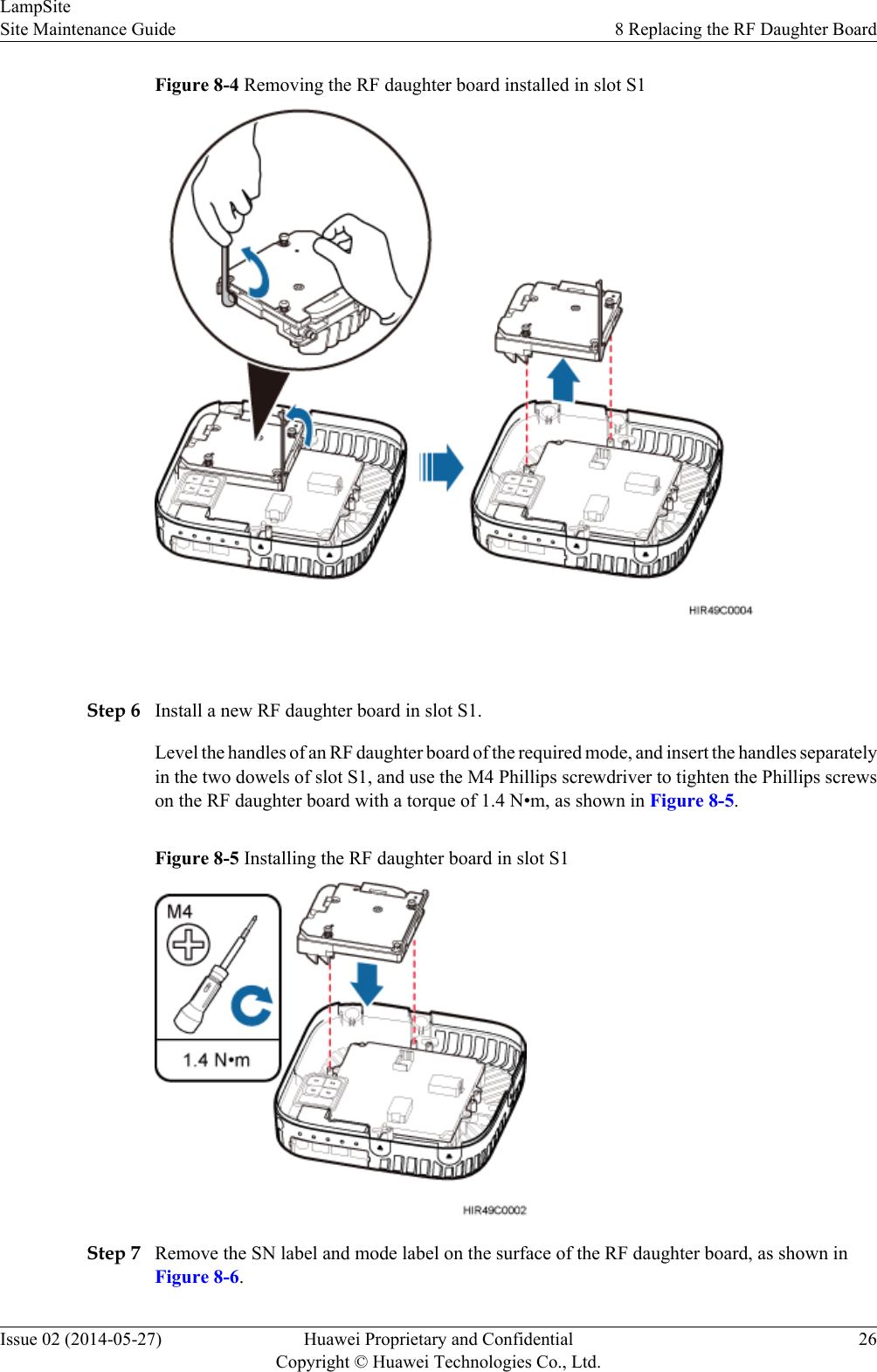
NOTElThe pRRU housing and the RF daughter board can be secured using either Phillips screws or protectionscrews, requiring the same installation operations. This section uses Phillips screws as an example todescribe the installation operations.lKeep the Phillips screw secure for future use.Step 5 Remove the RF daughter board installed in slot S1.NOTICEHold the RF daughter board tightly when pulling the handle to prevent the RF daughter boardfrom falling.1. Use the M4 Phillips screwdriver to loosen the Phillips screws on the RF daughter board inslot S1, as shown in Figure 8-3.Figure 8-3 Loosen the Phillips screws2. Use the left hand to hold the RF daughter board and the right hand to hold the right handleof the RF daughter board to remove the RF daughter board and put it into an ESD box orbag, as shown in Figure 8-4.LampSiteSite Maintenance Guide 8 Replacing the RF Daughter BoardIssue 02 (2014-05-27) Huawei Proprietary and ConfidentialCopyright © Huawei Technologies Co., Ltd.25
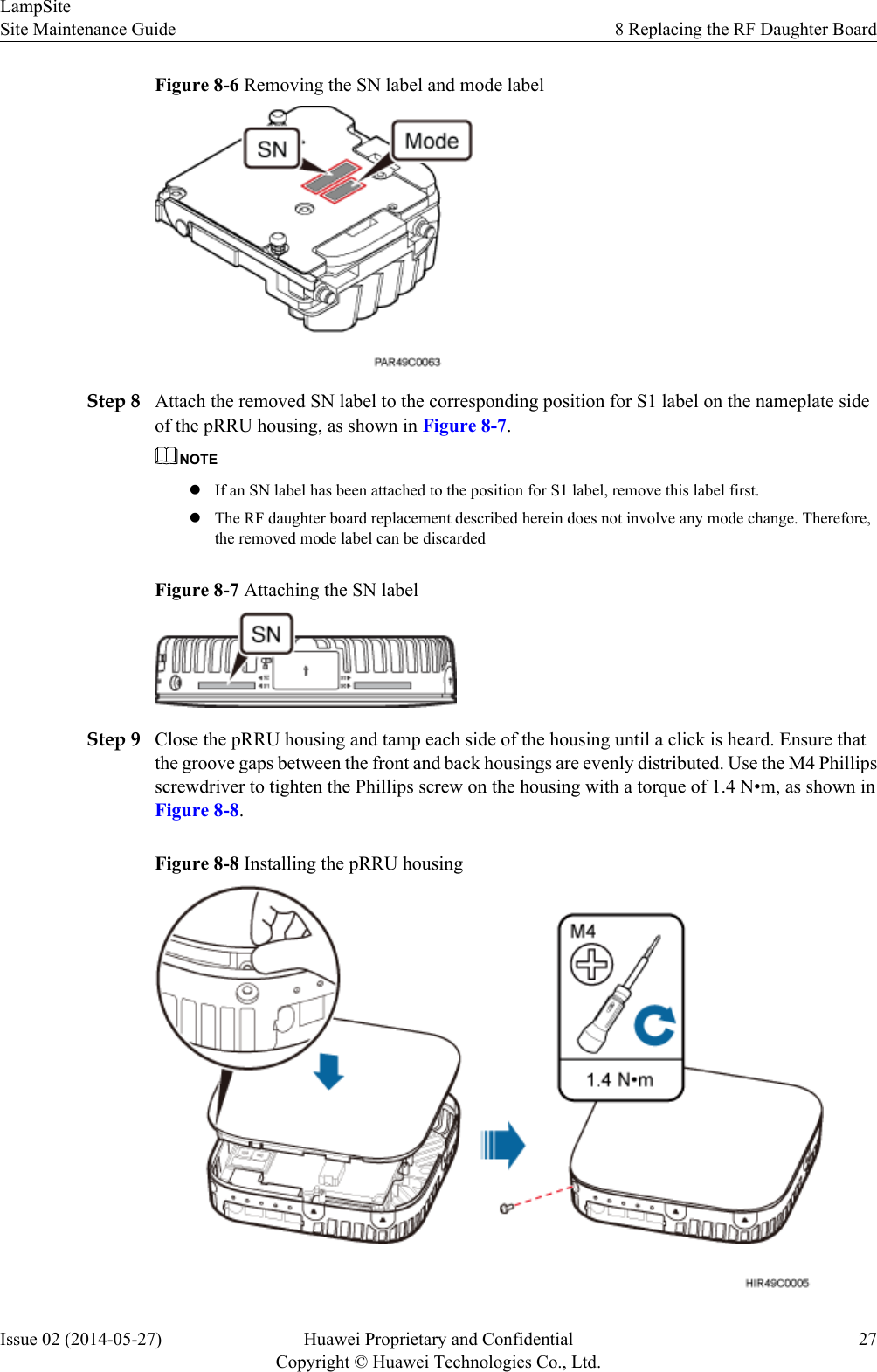
Figure 8-4 Removing the RF daughter board installed in slot S1 Step 6 Install a new RF daughter board in slot S1.Level the handles of an RF daughter board of the required mode, and insert the handles separatelyin the two dowels of slot S1, and use the M4 Phillips screwdriver to tighten the Phillips screwson the RF daughter board with a torque of 1.4 N•m, as shown in Figure 8-5.Figure 8-5 Installing the RF daughter board in slot S1Step 7 Remove the SN label and mode label on the surface of the RF daughter board, as shown inFigure 8-6.LampSiteSite Maintenance Guide 8 Replacing the RF Daughter BoardIssue 02 (2014-05-27) Huawei Proprietary and ConfidentialCopyright © Huawei Technologies Co., Ltd.26
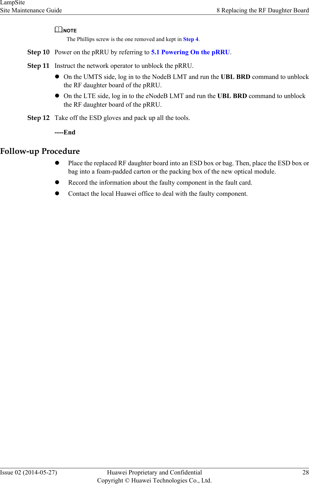
Figure 8-6 Removing the SN label and mode labelStep 8 Attach the removed SN label to the corresponding position for S1 label on the nameplate sideof the pRRU housing, as shown in Figure 8-7.NOTElIf an SN label has been attached to the position for S1 label, remove this label first.lThe RF daughter board replacement described herein does not involve any mode change. Therefore,the removed mode label can be discardedFigure 8-7 Attaching the SN labelStep 9 Close the pRRU housing and tamp each side of the housing until a click is heard. Ensure thatthe groove gaps between the front and back housings are evenly distributed. Use the M4 Phillipsscrewdriver to tighten the Phillips screw on the housing with a torque of 1.4 N•m, as shown inFigure 8-8.Figure 8-8 Installing the pRRU housingLampSiteSite Maintenance Guide 8 Replacing the RF Daughter BoardIssue 02 (2014-05-27) Huawei Proprietary and ConfidentialCopyright © Huawei Technologies Co., Ltd.27
NOTEThe Phillips screw is the one removed and kept in Step 4.Step 10 Power on the pRRU by referring to 5.1 Powering On the pRRU.Step 11 Instruct the network operator to unblock the pRRU.lOn the UMTS side, log in to the NodeB LMT and run the UBL BRD command to unblockthe RF daughter board of the pRRU.lOn the LTE side, log in to the eNodeB LMT and run the UBL BRD command to unblockthe RF daughter board of the pRRU.Step 12 Take off the ESD gloves and pack up all the tools.----EndFollow-up ProcedurelPlace the replaced RF daughter board into an ESD box or bag. Then, place the ESD box orbag into a foam-padded carton or the packing box of the new optical module.lRecord the information about the faulty component in the fault card.lContact the local Huawei office to deal with the faulty component.LampSiteSite Maintenance Guide 8 Replacing the RF Daughter BoardIssue 02 (2014-05-27) Huawei Proprietary and ConfidentialCopyright © Huawei Technologies Co., Ltd.28
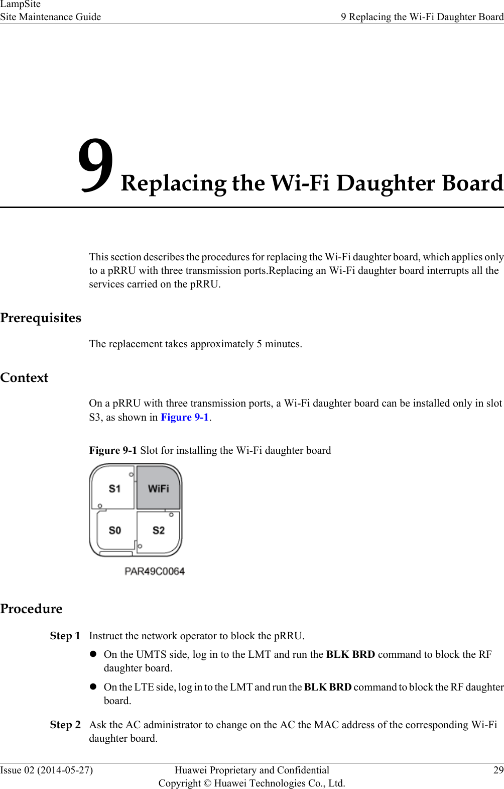
9 Replacing the Wi-Fi Daughter BoardThis section describes the procedures for replacing the Wi-Fi daughter board, which applies onlyto a pRRU with three transmission ports.Replacing an Wi-Fi daughter board interrupts all theservices carried on the pRRU.PrerequisitesThe replacement takes approximately 5 minutes.ContextOn a pRRU with three transmission ports, a Wi-Fi daughter board can be installed only in slotS3, as shown in Figure 9-1.Figure 9-1 Slot for installing the Wi-Fi daughter boardProcedureStep 1 Instruct the network operator to block the pRRU.lOn the UMTS side, log in to the LMT and run the BLK BRD command to block the RFdaughter board.lOn the LTE side, log in to the LMT and run the BLK BRD command to block the RF daughterboard.Step 2 Ask the AC administrator to change on the AC the MAC address of the corresponding Wi-Fidaughter board.LampSiteSite Maintenance Guide 9 Replacing the Wi-Fi Daughter BoardIssue 02 (2014-05-27) Huawei Proprietary and ConfidentialCopyright © Huawei Technologies Co., Ltd.29
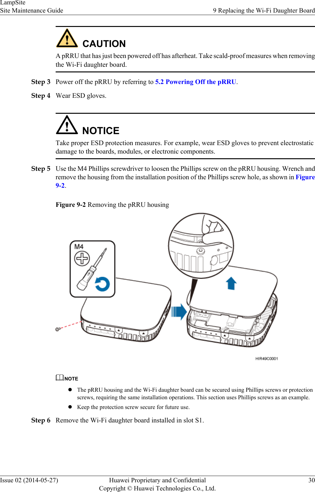
CAUTIONA pRRU that has just been powered off has afterheat. Take scald-proof measures when removingthe Wi-Fi daughter board.Step 3 Power off the pRRU by referring to 5.2 Powering Off the pRRU.Step 4 Wear ESD gloves.NOTICETake proper ESD protection measures. For example, wear ESD gloves to prevent electrostaticdamage to the boards, modules, or electronic components.Step 5 Use the M4 Phillips screwdriver to loosen the Phillips screw on the pRRU housing. Wrench andremove the housing from the installation position of the Phillips screw hole, as shown in Figure9-2.Figure 9-2 Removing the pRRU housingNOTElThe pRRU housing and the Wi-Fi daughter board can be secured using Phillips screws or protectionscrews, requiring the same installation operations. This section uses Phillips screws as an example.lKeep the protection screw secure for future use.Step 6 Remove the Wi-Fi daughter board installed in slot S1.LampSiteSite Maintenance Guide 9 Replacing the Wi-Fi Daughter BoardIssue 02 (2014-05-27) Huawei Proprietary and ConfidentialCopyright © Huawei Technologies Co., Ltd.30
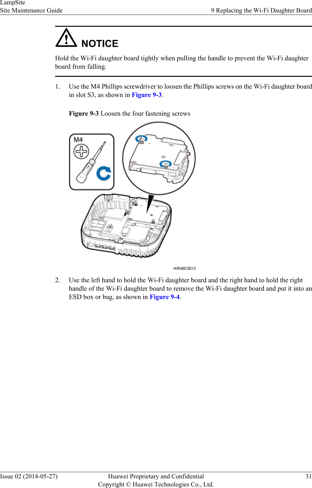
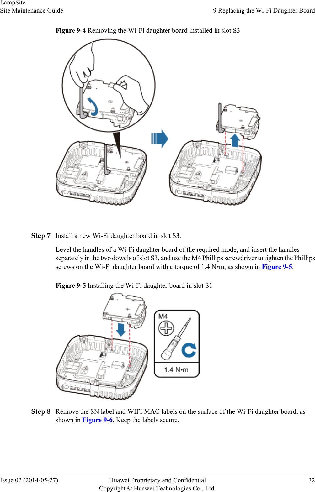
NOTICEHold the Wi-Fi daughter board tightly when pulling the handle to prevent the Wi-Fi daughterboard from falling.1. Use the M4 Phillips screwdriver to loosen the Phillips screws on the Wi-Fi daughter boardin slot S3, as shown in Figure 9-3.Figure 9-3 Loosen the four fastening screws2. Use the left hand to hold the Wi-Fi daughter board and the right hand to hold the righthandle of the Wi-Fi daughter board to remove the Wi-Fi daughter board and put it into anESD box or bag, as shown in Figure 9-4.LampSiteSite Maintenance Guide 9 Replacing the Wi-Fi Daughter BoardIssue 02 (2014-05-27) Huawei Proprietary and ConfidentialCopyright © Huawei Technologies Co., Ltd.31
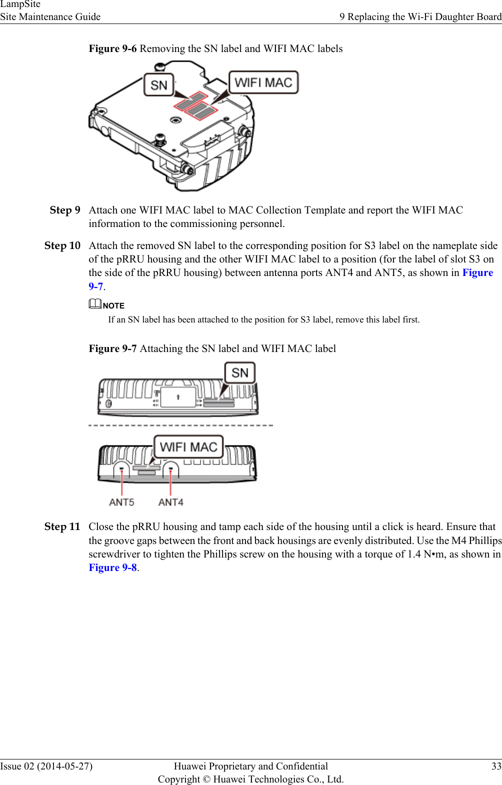
Figure 9-4 Removing the Wi-Fi daughter board installed in slot S3 Step 7 Install a new Wi-Fi daughter board in slot S3.Level the handles of a Wi-Fi daughter board of the required mode, and insert the handlesseparately in the two dowels of slot S3, and use the M4 Phillips screwdriver to tighten the Phillipsscrews on the Wi-Fi daughter board with a torque of 1.4 N•m, as shown in Figure 9-5.Figure 9-5 Installing the Wi-Fi daughter board in slot S1Step 8 Remove the SN label and WIFI MAC labels on the surface of the Wi-Fi daughter board, asshown in Figure 9-6. Keep the labels secure.LampSiteSite Maintenance Guide 9 Replacing the Wi-Fi Daughter BoardIssue 02 (2014-05-27) Huawei Proprietary and ConfidentialCopyright © Huawei Technologies Co., Ltd.32
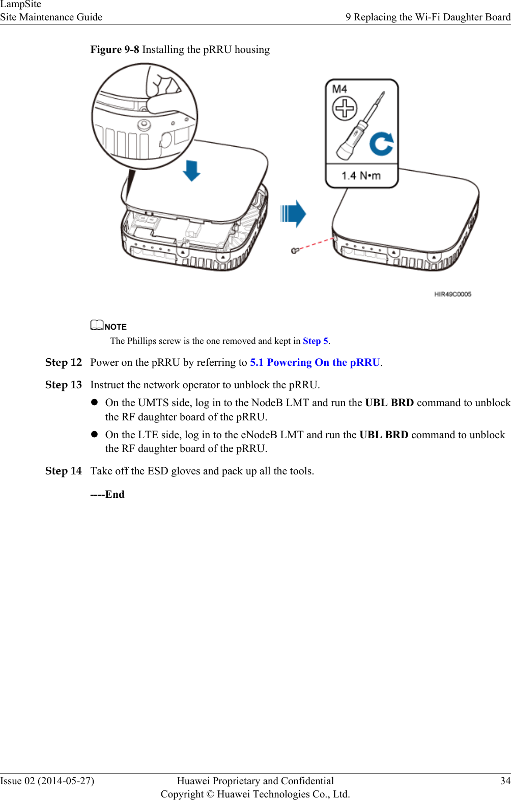
Figure 9-6 Removing the SN label and WIFI MAC labelsStep 9 Attach one WIFI MAC label to MAC Collection Template and report the WIFI MACinformation to the commissioning personnel.Step 10 Attach the removed SN label to the corresponding position for S3 label on the nameplate sideof the pRRU housing and the other WIFI MAC label to a position (for the label of slot S3 onthe side of the pRRU housing) between antenna ports ANT4 and ANT5, as shown in Figure9-7.NOTEIf an SN label has been attached to the position for S3 label, remove this label first.Figure 9-7 Attaching the SN label and WIFI MAC labelStep 11 Close the pRRU housing and tamp each side of the housing until a click is heard. Ensure thatthe groove gaps between the front and back housings are evenly distributed. Use the M4 Phillipsscrewdriver to tighten the Phillips screw on the housing with a torque of 1.4 N•m, as shown inFigure 9-8.LampSiteSite Maintenance Guide 9 Replacing the Wi-Fi Daughter BoardIssue 02 (2014-05-27) Huawei Proprietary and ConfidentialCopyright © Huawei Technologies Co., Ltd.33
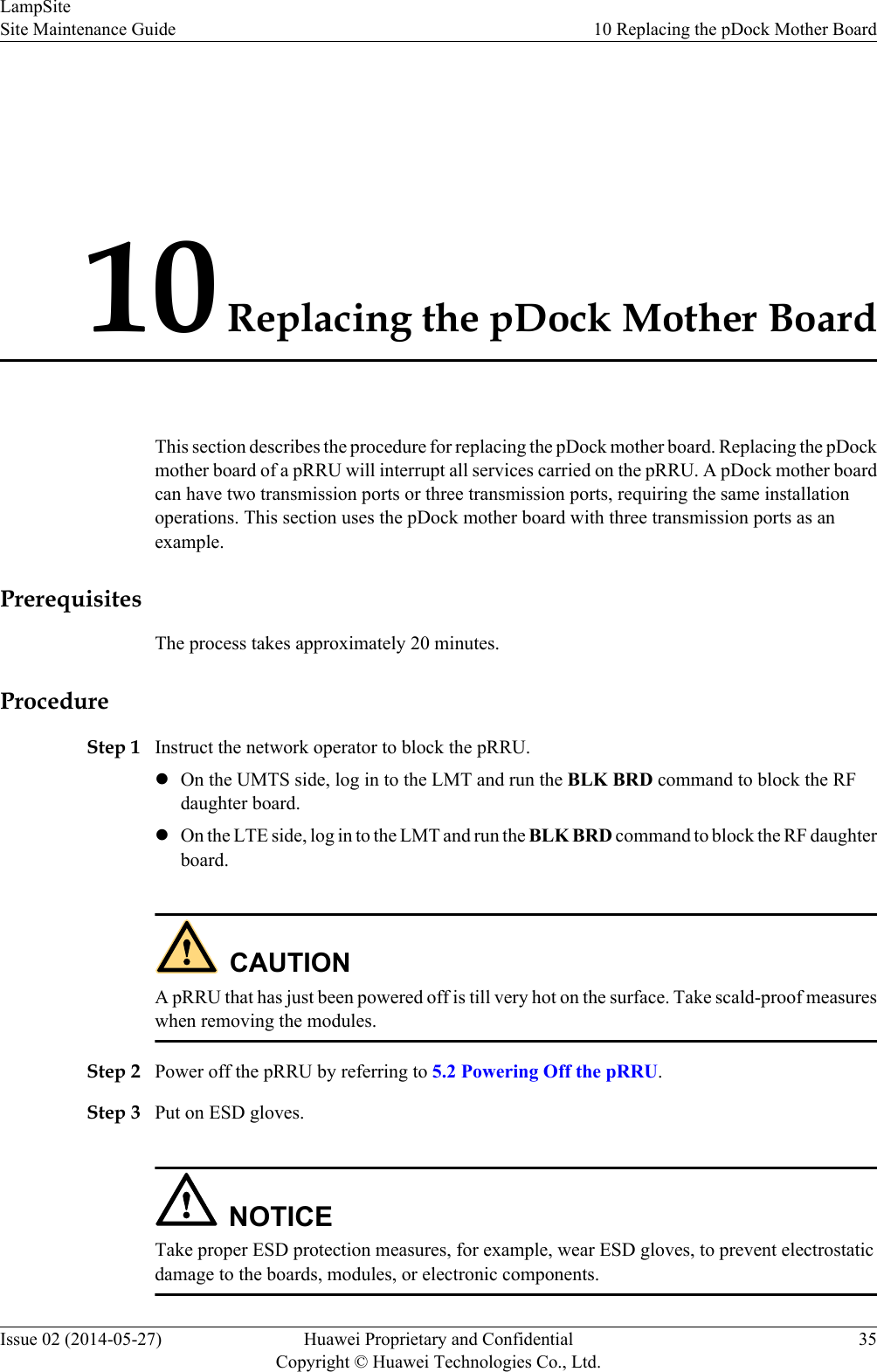
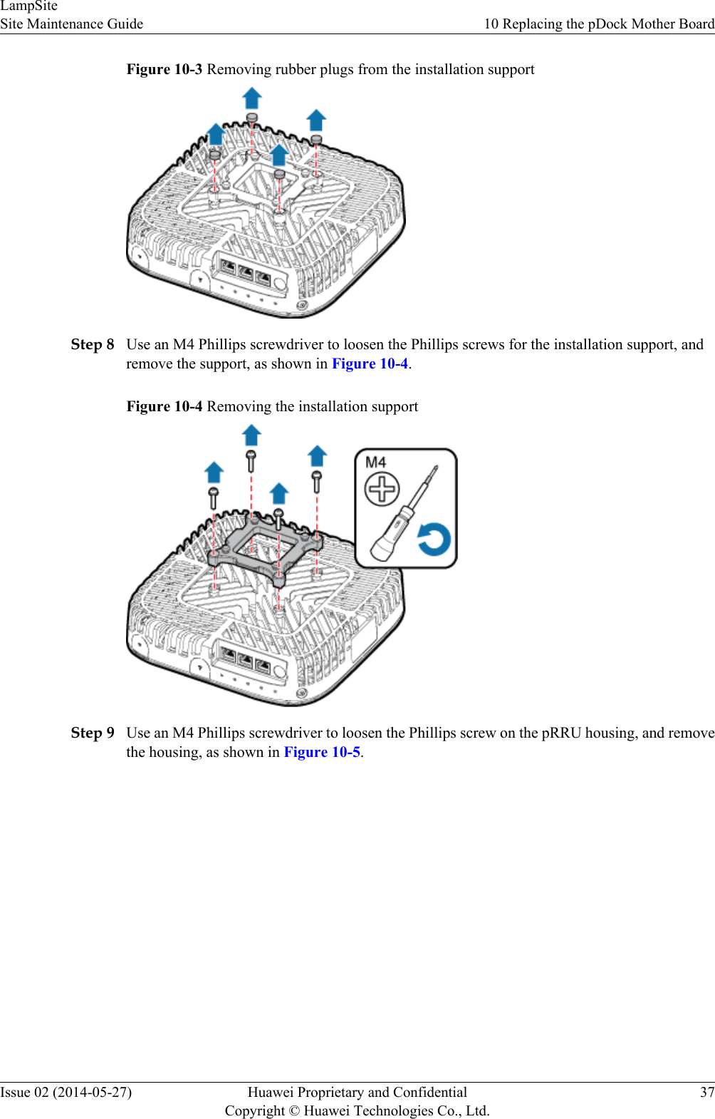
Figure 9-8 Installing the pRRU housingNOTEThe Phillips screw is the one removed and kept in Step 5.Step 12 Power on the pRRU by referring to 5.1 Powering On the pRRU.Step 13 Instruct the network operator to unblock the pRRU.lOn the UMTS side, log in to the NodeB LMT and run the UBL BRD command to unblockthe RF daughter board of the pRRU.lOn the LTE side, log in to the eNodeB LMT and run the UBL BRD command to unblockthe RF daughter board of the pRRU.Step 14 Take off the ESD gloves and pack up all the tools.----EndLampSiteSite Maintenance Guide 9 Replacing the Wi-Fi Daughter BoardIssue 02 (2014-05-27) Huawei Proprietary and ConfidentialCopyright © Huawei Technologies Co., Ltd.34
10 Replacing the pDock Mother BoardThis section describes the procedure for replacing the pDock mother board. Replacing the pDockmother board of a pRRU will interrupt all services carried on the pRRU. A pDock mother boardcan have two transmission ports or three transmission ports, requiring the same installationoperations. This section uses the pDock mother board with three transmission ports as anexample.PrerequisitesThe process takes approximately 20 minutes.ProcedureStep 1 Instruct the network operator to block the pRRU.lOn the UMTS side, log in to the LMT and run the BLK BRD command to block the RFdaughter board.lOn the LTE side, log in to the LMT and run the BLK BRD command to block the RF daughterboard.CAUTIONA pRRU that has just been powered off is till very hot on the surface. Take scald-proof measureswhen removing the modules.Step 2 Power off the pRRU by referring to 5.2 Powering Off the pRRU.Step 3 Put on ESD gloves.NOTICETake proper ESD protection measures, for example, wear ESD gloves, to prevent electrostaticdamage to the boards, modules, or electronic components.LampSiteSite Maintenance Guide 10 Replacing the pDock Mother BoardIssue 02 (2014-05-27) Huawei Proprietary and ConfidentialCopyright © Huawei Technologies Co., Ltd.35
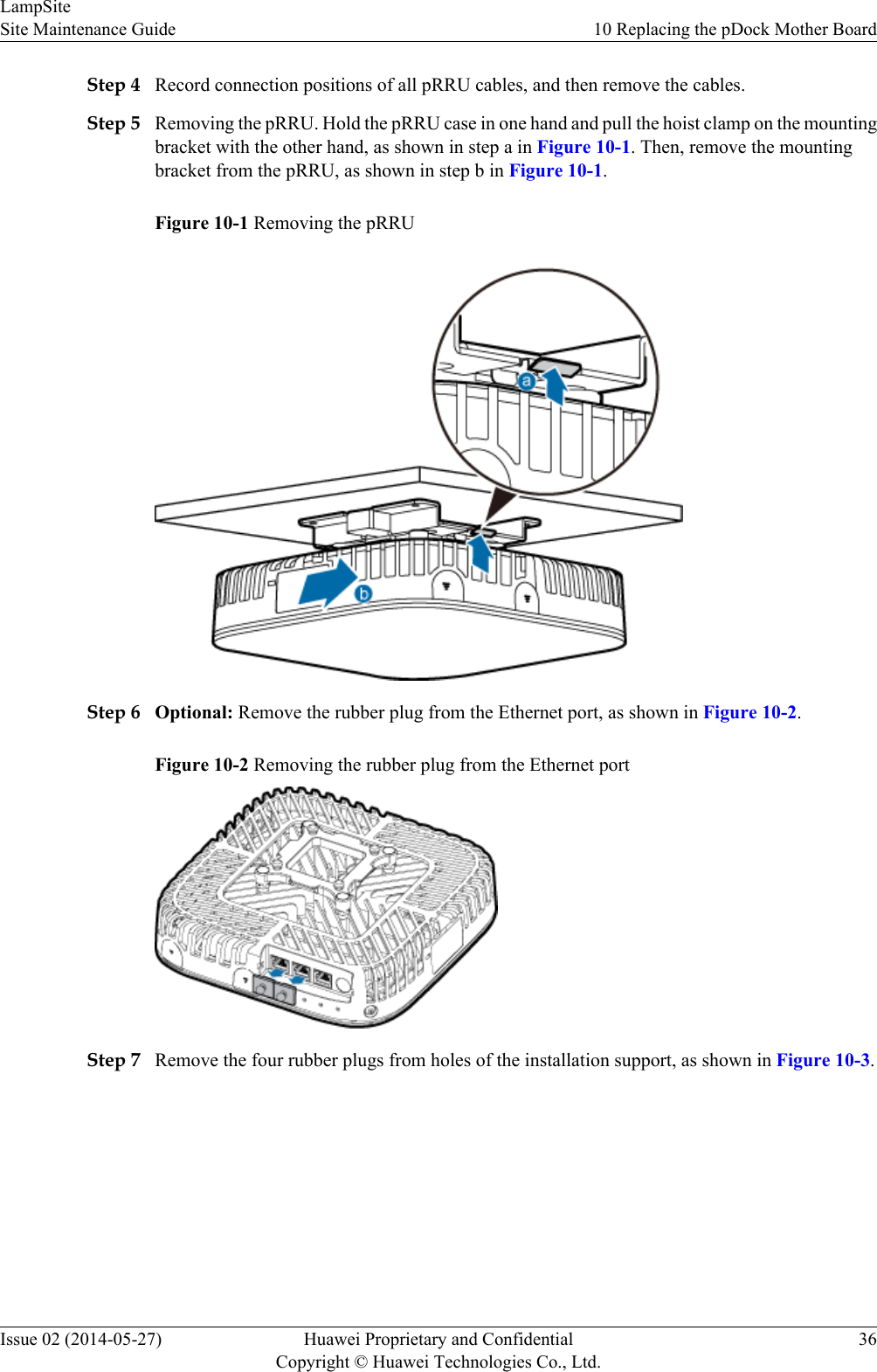
Step 4 Record connection positions of all pRRU cables, and then remove the cables.Step 5 Removing the pRRU. Hold the pRRU case in one hand and pull the hoist clamp on the mountingbracket with the other hand, as shown in step a in Figure 10-1. Then, remove the mountingbracket from the pRRU, as shown in step b in Figure 10-1.Figure 10-1 Removing the pRRUStep 6 Optional: Remove the rubber plug from the Ethernet port, as shown in Figure 10-2.Figure 10-2 Removing the rubber plug from the Ethernet portStep 7 Remove the four rubber plugs from holes of the installation support, as shown in Figure 10-3.LampSiteSite Maintenance Guide 10 Replacing the pDock Mother BoardIssue 02 (2014-05-27) Huawei Proprietary and ConfidentialCopyright © Huawei Technologies Co., Ltd.36
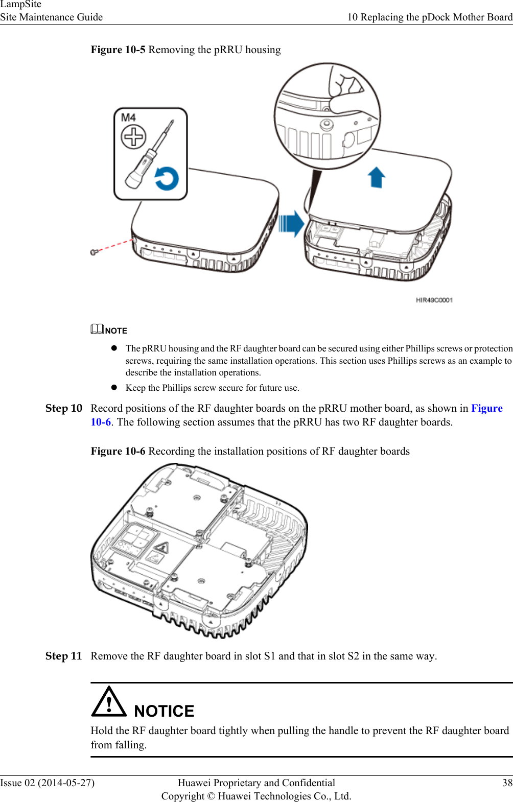
Figure 10-3 Removing rubber plugs from the installation supportStep 8 Use an M4 Phillips screwdriver to loosen the Phillips screws for the installation support, andremove the support, as shown in Figure 10-4.Figure 10-4 Removing the installation supportStep 9 Use an M4 Phillips screwdriver to loosen the Phillips screw on the pRRU housing, and removethe housing, as shown in Figure 10-5.LampSiteSite Maintenance Guide 10 Replacing the pDock Mother BoardIssue 02 (2014-05-27) Huawei Proprietary and ConfidentialCopyright © Huawei Technologies Co., Ltd.37
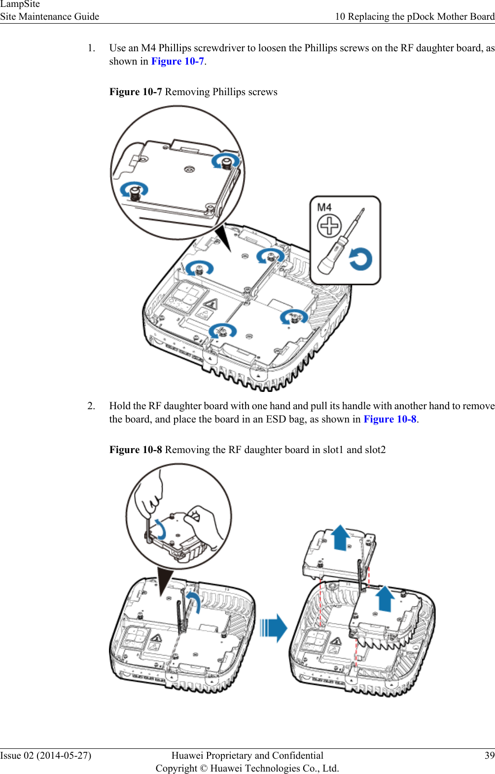
Figure 10-5 Removing the pRRU housingNOTElThe pRRU housing and the RF daughter board can be secured using either Phillips screws or protectionscrews, requiring the same installation operations. This section uses Phillips screws as an example todescribe the installation operations.lKeep the Phillips screw secure for future use.Step 10 Record positions of the RF daughter boards on the pRRU mother board, as shown in Figure10-6. The following section assumes that the pRRU has two RF daughter boards.Figure 10-6 Recording the installation positions of RF daughter boardsStep 11 Remove the RF daughter board in slot S1 and that in slot S2 in the same way.NOTICEHold the RF daughter board tightly when pulling the handle to prevent the RF daughter boardfrom falling.LampSiteSite Maintenance Guide 10 Replacing the pDock Mother BoardIssue 02 (2014-05-27) Huawei Proprietary and ConfidentialCopyright © Huawei Technologies Co., Ltd.38
1. Use an M4 Phillips screwdriver to loosen the Phillips screws on the RF daughter board, asshown in Figure 10-7.Figure 10-7 Removing Phillips screws2. Hold the RF daughter board with one hand and pull its handle with another hand to removethe board, and place the board in an ESD bag, as shown in Figure 10-8.Figure 10-8 Removing the RF daughter board in slot1 and slot2 LampSiteSite Maintenance Guide 10 Replacing the pDock Mother BoardIssue 02 (2014-05-27) Huawei Proprietary and ConfidentialCopyright © Huawei Technologies Co., Ltd.39
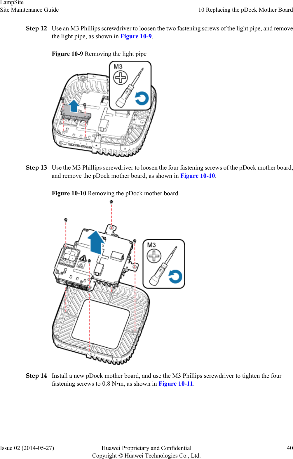
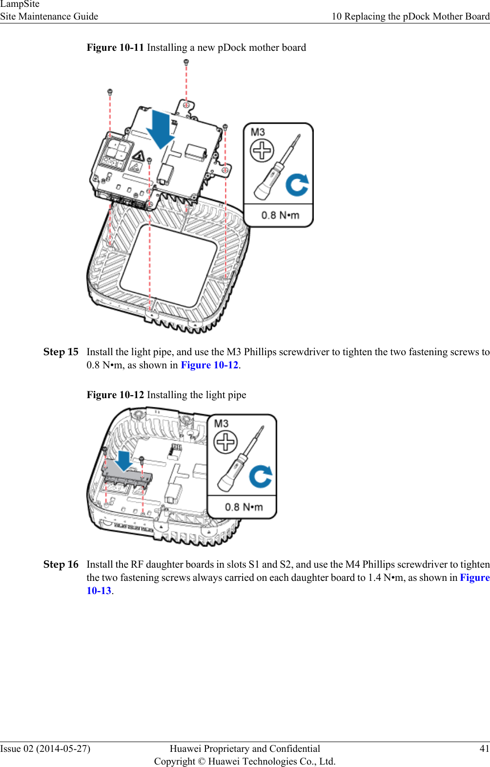
Step 12 Use an M3 Phillips screwdriver to loosen the two fastening screws of the light pipe, and removethe light pipe, as shown in Figure 10-9.Figure 10-9 Removing the light pipeStep 13 Use the M3 Phillips screwdriver to loosen the four fastening screws of the pDock mother board,and remove the pDock mother board, as shown in Figure 10-10.Figure 10-10 Removing the pDock mother boardStep 14 Install a new pDock mother board, and use the M3 Phillips screwdriver to tighten the fourfastening screws to 0.8 N•m, as shown in Figure 10-11.LampSiteSite Maintenance Guide 10 Replacing the pDock Mother BoardIssue 02 (2014-05-27) Huawei Proprietary and ConfidentialCopyright © Huawei Technologies Co., Ltd.40
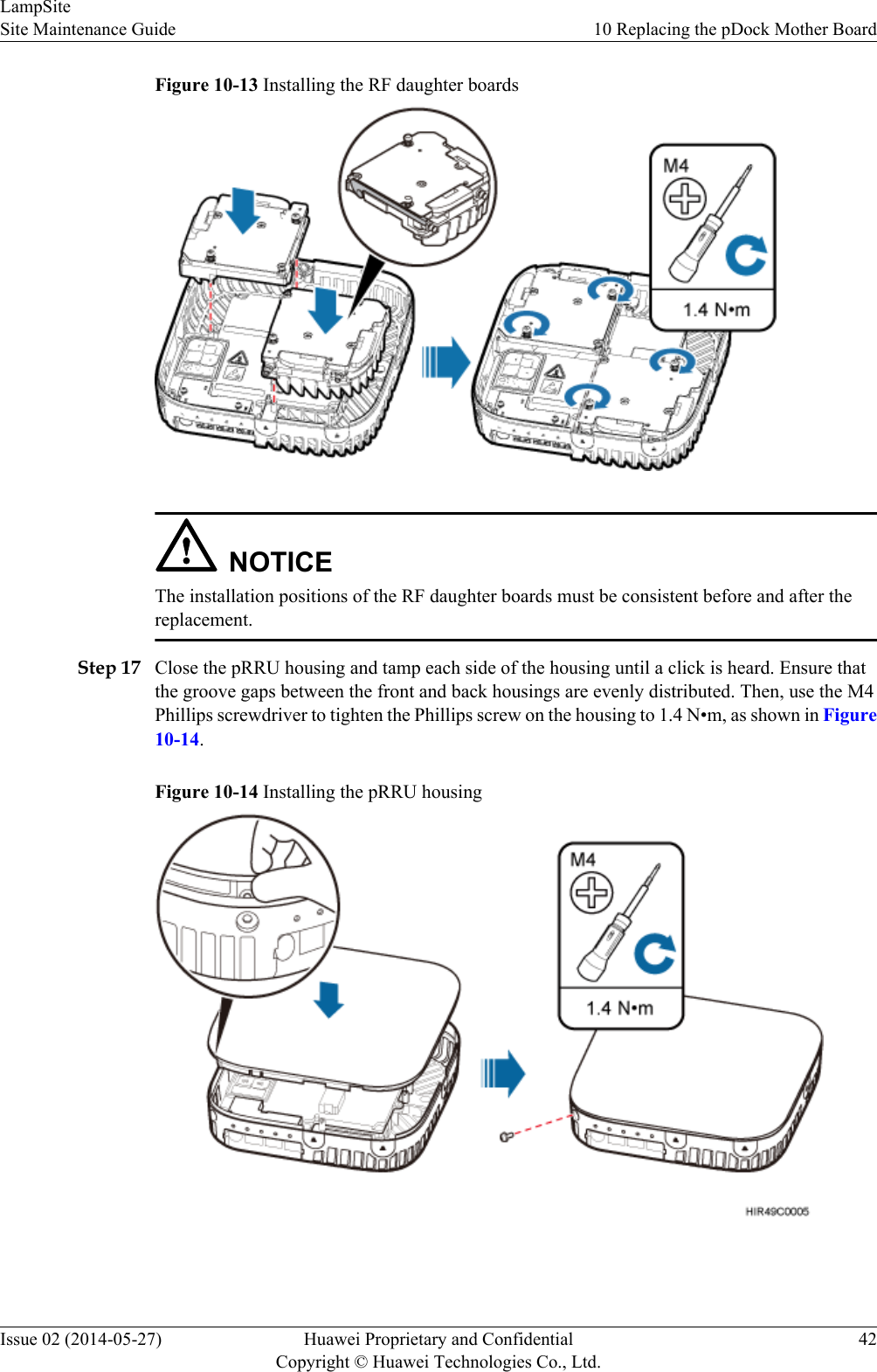
Figure 10-11 Installing a new pDock mother boardStep 15 Install the light pipe, and use the M3 Phillips screwdriver to tighten the two fastening screws to0.8 N•m, as shown in Figure 10-12.Figure 10-12 Installing the light pipeStep 16 Install the RF daughter boards in slots S1 and S2, and use the M4 Phillips screwdriver to tightenthe two fastening screws always carried on each daughter board to 1.4 N•m, as shown in Figure10-13.LampSiteSite Maintenance Guide 10 Replacing the pDock Mother BoardIssue 02 (2014-05-27) Huawei Proprietary and ConfidentialCopyright © Huawei Technologies Co., Ltd.41
Figure 10-13 Installing the RF daughter boardsNOTICEThe installation positions of the RF daughter boards must be consistent before and after thereplacement.Step 17 Close the pRRU housing and tamp each side of the housing until a click is heard. Ensure thatthe groove gaps between the front and back housings are evenly distributed. Then, use the M4Phillips screwdriver to tighten the Phillips screw on the housing to 1.4 N•m, as shown in Figure10-14.Figure 10-14 Installing the pRRU housingLampSiteSite Maintenance Guide 10 Replacing the pDock Mother BoardIssue 02 (2014-05-27) Huawei Proprietary and ConfidentialCopyright © Huawei Technologies Co., Ltd.42
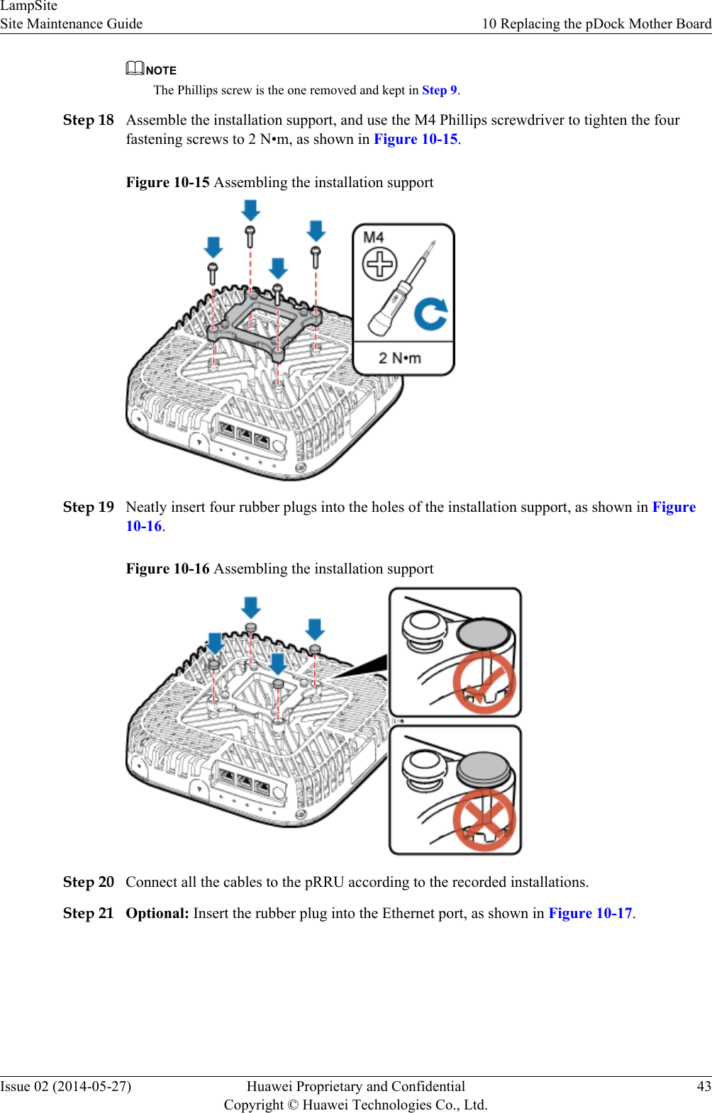
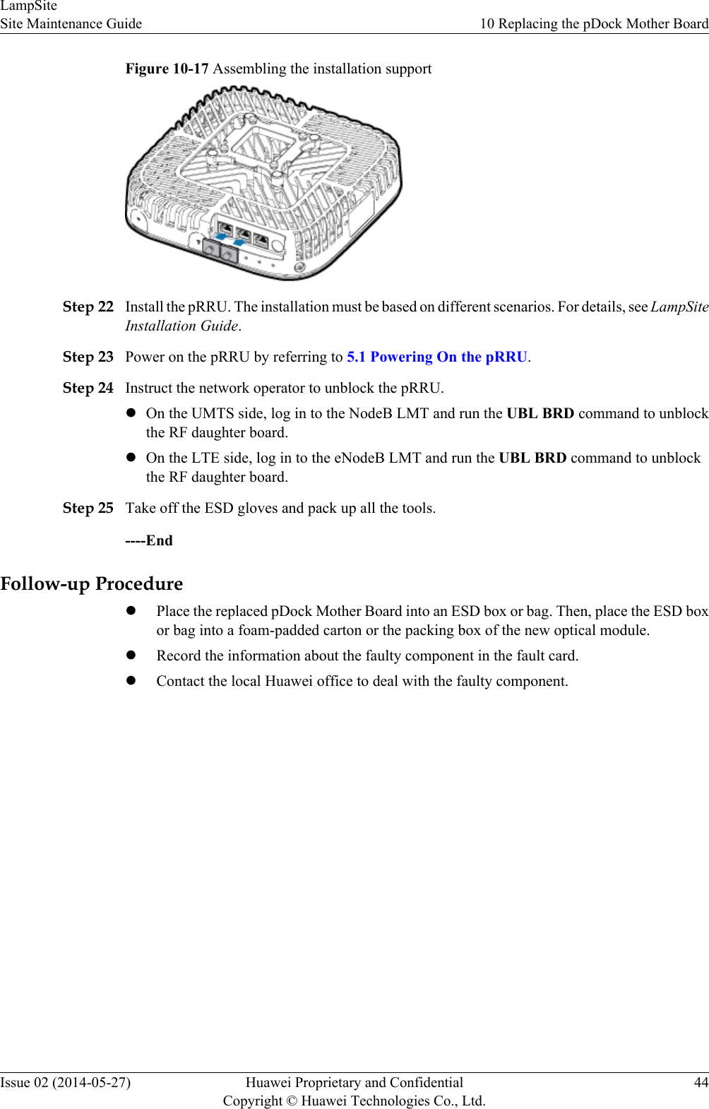
NOTEThe Phillips screw is the one removed and kept in Step 9.Step 18 Assemble the installation support, and use the M4 Phillips screwdriver to tighten the fourfastening screws to 2 N•m, as shown in Figure 10-15.Figure 10-15 Assembling the installation supportStep 19 Neatly insert four rubber plugs into the holes of the installation support, as shown in Figure10-16.Figure 10-16 Assembling the installation supportStep 20 Connect all the cables to the pRRU according to the recorded installations.Step 21 Optional: Insert the rubber plug into the Ethernet port, as shown in Figure 10-17.LampSiteSite Maintenance Guide 10 Replacing the pDock Mother BoardIssue 02 (2014-05-27) Huawei Proprietary and ConfidentialCopyright © Huawei Technologies Co., Ltd.43
Figure 10-17 Assembling the installation supportStep 22 Install the pRRU. The installation must be based on different scenarios. For details, see LampSiteInstallation Guide.Step 23 Power on the pRRU by referring to 5.1 Powering On the pRRU.Step 24 Instruct the network operator to unblock the pRRU.lOn the UMTS side, log in to the NodeB LMT and run the UBL BRD command to unblockthe RF daughter board.lOn the LTE side, log in to the eNodeB LMT and run the UBL BRD command to unblockthe RF daughter board.Step 25 Take off the ESD gloves and pack up all the tools.----EndFollow-up ProcedurelPlace the replaced pDock Mother Board into an ESD box or bag. Then, place the ESD boxor bag into a foam-padded carton or the packing box of the new optical module.lRecord the information about the faulty component in the fault card.lContact the local Huawei office to deal with the faulty component.LampSiteSite Maintenance Guide 10 Replacing the pDock Mother BoardIssue 02 (2014-05-27) Huawei Proprietary and ConfidentialCopyright © Huawei Technologies Co., Ltd.44

Navigation menu