Huawei Technologies PRRU3901 pico Remote Radio Unit User Manual Site Maintenance Guide
Huawei Technologies Co.,Ltd pico Remote Radio Unit Site Maintenance Guide
Contents
- 1. UserManual_LampSite Installation Guide(02)(PDF)-EN.pdf
- 2. UserManual_pRRU3901 Compliance and Safety Manual.pdf
- 3. UserManual_LampSite Site Maintenance Guide(02)(PDF)-EN.pdf
UserManual_LampSite Site Maintenance Guide(02)(PDF)-EN.pdf
LampSite
Site Maintenance Guide
Issue 02
Date 2014-05-27
HUAWEI TECHNOLOGIES CO., LTD.

Copyright © Huawei Technologies Co., Ltd. 2014. All rights reserved.
No part of this document may be reproduced or transmitted in any form or by any means without prior written
consent of Huawei Technologies Co., Ltd.
Trademarks and Permissions
and other Huawei trademarks are trademarks of Huawei Technologies Co., Ltd.
All other trademarks and trade names mentioned in this document are the property of their respective holders.
Notice
The purchased products, services and features are stipulated by the contract made between Huawei and the
customer. All or part of the products, services and features described in this document may not be within the
purchase scope or the usage scope. Unless otherwise specified in the contract, all statements, information,
and recommendations in this document are provided "AS IS" without warranties, guarantees or representations
of any kind, either express or implied.
The information in this document is subject to change without notice. Every effort has been made in the
preparation of this document to ensure accuracy of the contents, but all statements, information, and
recommendations in this document do not constitute a warranty of any kind, express or implied.
Huawei Technologies Co., Ltd.
Address: Huawei Industrial Base
Bantian, Longgang
Shenzhen 518129
People's Republic of China
Website: http://www.huawei.com
Email: support@huawei.com
Issue 02 (2014-05-27) Huawei Proprietary and Confidential
Copyright © Huawei Technologies Co., Ltd.
i
About This Document
Overview
This document describes routine maintenance items for a RHUB3908 and pRRU3901, such as
equipment maintenance, and power-on and power-off operations. It also explains how to replace
the components and modules.
Product Version
The following table lists the product version related to this document.
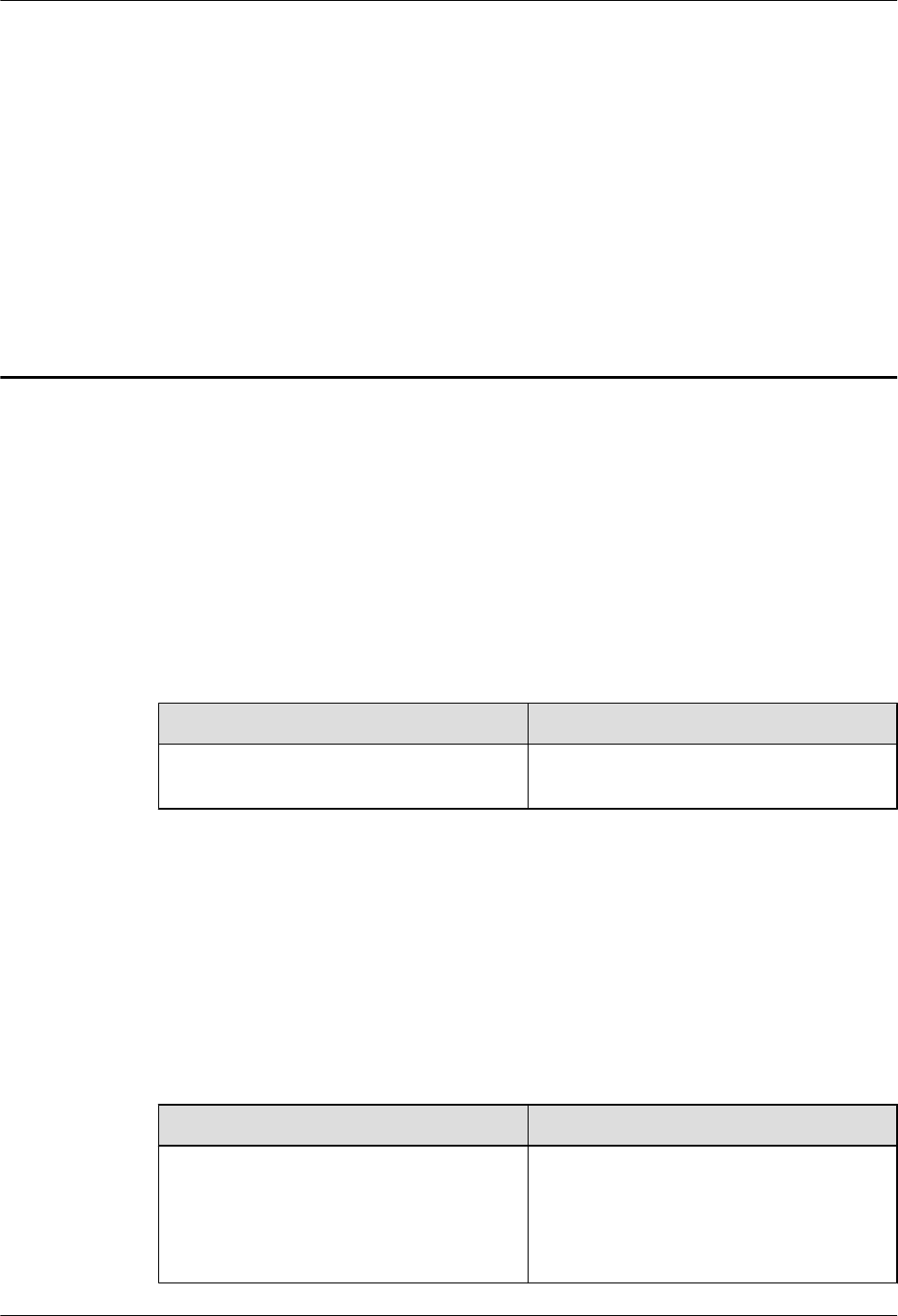
Product Name Product Version
RHUB3908 (referred to as RHUB in this
document)
V100R009C00 and later versions
Single-mode versions mapping
V100R009C00:
lNodeB: V200R016C00
leNodeB: V100R007C00
pRRU3901 (referred to as pRRU in this
document)
Intended Audience
This document is intended for:
lSystem engineers
lSite maintenance engineers
Organization
1 Changes in LampSite Site Maintenance Guide
This chapter provides information about the changes in different document versions of LampSite
Site Maintenance Guide.
2 RHUB Maintenance Items
LampSite
Site Maintenance Guide About This Document
Issue 02 (2014-05-27) Huawei Proprietary and Confidential
Copyright © Huawei Technologies Co., Ltd.
ii

This chapter describes the RHUB maintenance items, involving the equipment room, equipment,
power system, and grounding system.
3 pRRU Maintenance Items
This chapter describes the pRRU maintenance items, involving equipment and power system.
4 Powering On and Powering Off the RHUB
After the RHUB is powered on, check the indicator status. Power off the RHUB in normal or
emergency mode as required.
5 Powering On and Powering Off the pRRU
After the pRRU is powered on, check the power supply voltage and indicator status. Power off
the pRRU based on the power supply mode.
6 Replacing the RHUB
The RHUB is an indoor convergence unit. It converges multiple pRRUs to the BBU. Replacing
the RHUB interrupts services carried on the serving cell.
7 Replacing an Optical Module
An optical module provides a port for opto-electronic conversion. This enables the transmission
between the RHUB and BBU through the optical fiber. Replacing the optical module requires
removing the optical fibers. This interrupts all the services.
8 Replacing the RF Daughter Board
This section describes the procedures for replacing the RF daughter board of the pRRU. A pRRU
can have two transmission ports or three transmission ports, requiring the same installation
operations. This section uses the pRRU with three transmission ports as an example. Replacing
an RF daughter board interrupts all the services carried on the pRRU.
9 Replacing the Wi-Fi Daughter Board
This section describes the procedures for replacing the Wi-Fi daughter board, which applies only
to a pRRU with three transmission ports.Replacing an Wi-Fi daughter board interrupts all the
services carried on the pRRU.
10 Replacing the pDock Mother Board
This section describes the procedure for replacing the pDock mother board. Replacing the pDock
mother board of a pRRU will interrupt all services carried on the pRRU. A pDock mother board
can have two transmission ports or three transmission ports, requiring the same installation
operations. This section uses the pDock mother board with three transmission ports as an
example.
Conventions
Symbol Conventions
The symbols that may be found in this document are defined as follows.
LampSite
Site Maintenance Guide About This Document
Issue 02 (2014-05-27) Huawei Proprietary and Confidential
Copyright © Huawei Technologies Co., Ltd.
iii
Symbol Description
Indicates an imminently hazardous situation which, if not
avoided, will result in death or serious injury.
Indicates a potentially hazardous situation which, if not
avoided, could result in death or serious injury.
Indicates a potentially hazardous situation which, if not
avoided, may result in minor or moderate injury.
Indicates a potentially hazardous situation which, if not
avoided, could result in equipment damage, data loss,
performance deterioration, or unanticipated results.
NOTICE is used to address practices not related to personal
injury.
Calls attention to important information, best practices and
tips.
NOTE is used to address information not related to personal
injury, equipment damage, and environment deterioration.
General Conventions
The general conventions that may be found in this document are defined as follows.
Convention Description
Times New Roman Normal paragraphs are in Times New Roman.
Boldface Names of files, directories, folders, and users are in
boldface. For example, log in as user root.
Italic Book titles are in italics.
Courier New Examples of information displayed on the screen are in
Courier New.
Command Conventions
The command conventions that may be found in this document are defined as follows.
Convention Description
Boldface The keywords of a command line are in boldface.
Italic Command arguments are in italics.
LampSite
Site Maintenance Guide About This Document
Issue 02 (2014-05-27) Huawei Proprietary and Confidential
Copyright © Huawei Technologies Co., Ltd.
iv
Convention Description
[ ] Items (keywords or arguments) in brackets [ ] are optional.
{ x | y | ... } Optional items are grouped in braces and separated by
vertical bars. One item is selected.
[ x | y | ... ] Optional items are grouped in brackets and separated by
vertical bars. One item is selected or no item is selected.
{ x | y | ... }*Optional items are grouped in braces and separated by
vertical bars. A minimum of one item or a maximum of all
items can be selected.
[ x | y | ... ]*Optional items are grouped in brackets and separated by
vertical bars. Several items or no item can be selected.
GUI Conventions
The GUI conventions that may be found in this document are defined as follows.
Convention Description
Boldface Buttons, menus, parameters, tabs, window, and dialog titles
are in boldface. For example, click OK.
>Multi-level menus are in boldface and separated by the ">"
signs. For example, choose File > Create > Folder.
Keyboard Operations
The keyboard operations that may be found in this document are defined as follows.
Format Description
Key Press the key. For example, press Enter and press Tab.
Key 1+Key 2 Press the keys concurrently. For example, pressing Ctrl+Alt
+A means the three keys should be pressed concurrently.
Key 1, Key 2 Press the keys in turn. For example, pressing Alt, A means
the two keys should be pressed in turn.
Mouse Operations
The mouse operations that may be found in this document are defined as follows.
LampSite
Site Maintenance Guide About This Document
Issue 02 (2014-05-27) Huawei Proprietary and Confidential
Copyright © Huawei Technologies Co., Ltd.
v

Action Description
Click Select and release the primary mouse button without moving
the pointer.
Double-click Press the primary mouse button twice continuously and
quickly without moving the pointer.
Drag Press and hold the primary mouse button and move the
pointer to a certain position.
LampSite
Site Maintenance Guide About This Document
Issue 02 (2014-05-27) Huawei Proprietary and Confidential
Copyright © Huawei Technologies Co., Ltd.
vi

Contents
About This Document.....................................................................................................................ii
1 Changes in LampSite Site Maintenance Guide.......................................................................1
2 RHUB Maintenance Items...........................................................................................................4
3 pRRU Maintenance Items............................................................................................................8
4 Powering On and Powering Off the RHUB...........................................................................10
4.1 Powering On the RHUB...............................................................................................................................................11
4.2 Powering Off the RHUB..............................................................................................................................................12
5 Powering On and Powering Off the pRRU............................................................................13
5.1 Powering On the pRRU................................................................................................................................................14
5.2 Powering Off the pRRU...............................................................................................................................................15
6 Replacing the RHUB...................................................................................................................16
7 Replacing an Optical Module...................................................................................................20
8 Replacing the RF Daughter Board............................................................................................23
9 Replacing the Wi-Fi Daughter Board......................................................................................29
10 Replacing the pDock Mother Board......................................................................................35
LampSite
Site Maintenance Guide Contents
Issue 02 (2014-05-27) Huawei Proprietary and Confidential
Copyright © Huawei Technologies Co., Ltd.
vii
1 Changes in LampSite Site Maintenance
Guide
This chapter provides information about the changes in different document versions of LampSite
Site Maintenance Guide.
02 (2014-05-27)
This is the second commercial release.
Compared with 01 (2014-04-26), no information is added.
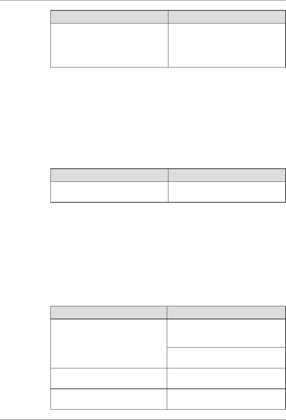
Compared with 01 (2014-04-26), this issue incorporates the following change:
Content Change Description
Entire document Added the descriptions about the LTE FDD
+LTE FDD mode.
Compared with 01 (2014-04-26), no information is deleted.
01 (2014-04-26)
This is the first commercial release.
Compared with Draft C (2014-03-26), no information is added.
Compared with Draft C (2014-03-26), this issue incorporates the following change:
Content Change Description
Entire document Changed the pRRU name from pRRU with
two Ethernet ports to pRRU with two
transmission ports, and pRRU with three
Ethernet ports to pRRU with three
transmission ports.
LampSite
Site Maintenance Guide 1 Changes in LampSite Site Maintenance Guide
Issue 02 (2014-05-27) Huawei Proprietary and Confidential
Copyright © Huawei Technologies Co., Ltd.
1
Content Change Description
10 Replacing the pDock Mother Board Changed the pDock name from pDock with
two Ethernet ports to pDock with two
transmission ports, and pDock with three
Ethernet ports to pDock with three
transmission ports.
Compared with Draft C (2014-03-26), this issue excludes the following topic:
lReplacing a PSU
Draft C (2014-03-26)
This is a draft release.
Compared with Draft B (2014-02-28), no information is added.
Compared with Draft B (2014-02-28), this issue incorporates the following change:
Content Change Description
6 Replacing the RHUB Deleted the operation of resetting the RHUB
after replacing.
Compared with Draft B (2014-02-28), no information is deleted.
Draft B (2014-02-28)
This is a draft release.
Compared with draft A (2013-11-30), this issue includes the following new topic:
l9 Replacing the Wi-Fi Daughter Board
Compared with draft A (2013-11-30), this issue incorporates the following changes:
Content Change Description
Entire document Added descriptions about pRRUs with three
transmission ports. Such pRRUs support
integrated Wi-Fi services.
Added the descriptions about the UMTS, LTE
FDD and UMTS+LTE FDD mode.
About This Document Optimized descriptions about matching
product versions.
8 Replacing the RF Daughter Board Added the procedures for removing and
attaching labels.
LampSite
Site Maintenance Guide 1 Changes in LampSite Site Maintenance Guide
Issue 02 (2014-05-27) Huawei Proprietary and Confidential
Copyright © Huawei Technologies Co., Ltd.
2

Content Change Description
9 Replacing the Wi-Fi Daughter Board
Compared with draft A (2013-11-30), this issue excludes the following topic:
lReplacing the pRRU
Draft A (2013-11-30)
This is a draft release.
LampSite
Site Maintenance Guide 1 Changes in LampSite Site Maintenance Guide
Issue 02 (2014-05-27) Huawei Proprietary and Confidential
Copyright © Huawei Technologies Co., Ltd.
3

2 RHUB Maintenance Items
This chapter describes the RHUB maintenance items, involving the equipment room, equipment,
power system, and grounding system.
Equipment Room Maintenance Items
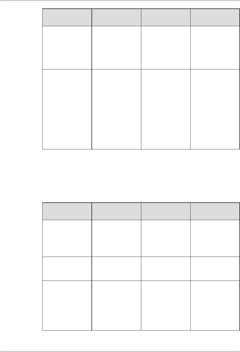
Table 2-1 lists the equipment room maintenance items.
Table 2-1 Equipment room maintenance items
Item Check Frequency Operation Reference
Standard
Environment alarms
in the equipment
room
Daily Check whether any
power alarm, fire
alarm, or smoke
alarm is reported.
No power alarm, fire
alarm, or smoke
alarm is reported.
Temperature in the
equipment room
Each time
maintenance is
performed
Record temperatures
in the equipment
room measured by a
thermometer.
-5°C to 45°C
Humidity in the
equipment room
Each time
maintenance is
performed
Record humidity in
the equipment room
measured by a
hygrometer.
5%RH to 95%RH
Lighting system in
the equipment room
Every other month Check whether the
routine lighting
system and
emergency lighting
system are running
properly.
-
Air conditioner Every other month Check whether the
air conditioner is
running properly.
-
LampSite
Site Maintenance Guide 2 RHUB Maintenance Items
Issue 02 (2014-05-27) Huawei Proprietary and Confidential
Copyright © Huawei Technologies Co., Ltd.
4

Item Check Frequency Operation Reference
Standard
Disaster protection
devices
Every one month Check whether the
disaster protection,
equipment
protection, and
firefighting devices
are normal.
lThe equipment
room is equipped
with portable
foam-type
extinguishers,
and the pressure
and expiration
date must be
checked.
lThe equipment
room has no
mice, ants, flying
insects, or other
risks.
Cleanness Every one month Check whether the
cabinet, equipment
housing, equipment
interior, desktop,
floor, door, and
window are clean
and tidy.
All these items are
clean and tidy.
Equipment Maintenance Items
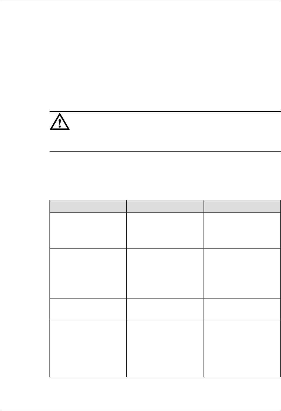
Table 2-2 lists the equipment maintenance items.
Table 2-2 Equipment maintenance items
Item Check Frequency Operation Reference
Standard
Fan in the PSU Monthly or quarterly Check whether the
fan is working
properly.
The fan works
properly without any
abnormal smell or
sound.
Equipment surface Monthly or quarterly Check whether the
equipment surface is
intact.
The equipment
surface is intact and
the label of the
cabinet is legible.
Equipment cleanness Monthly or quarterly Check whether the
equipment is clean.
The equipment
surface is clean.
LampSite
Site Maintenance Guide 2 RHUB Maintenance Items
Issue 02 (2014-05-27) Huawei Proprietary and Confidential
Copyright © Huawei Technologies Co., Ltd.
5
Item Check Frequency Operation Reference
Standard
Indicators Monthly or quarterly Check whether the
indicators on the
equipment are
working properly.
For details about the
indicator status, see
RHUB Ports and
Indicators in
LampSite Hardware
Description.
Electrostatic
discharge (ESD)
wrist strap
Quarterly Check the ESD wrist
strap in either of the
following ways:
lUse an ESD wrist
strap tester to
check the ESD
wrist strap.
lUse a multimeter
to test the ground
resistance of the
ESD wrist strap.
If you use an ESD
wrist strap tester, the
GOOD indicator is
on. If you use a
multimeter, the
ground resistance of
the ESD wrist strap
ranges from 0.75
ohms to 10 ohms.
Maintenance Items for the Power System and Grounding System
Table 2-3 lists the maintenance items for the power system and grounding system.
Table 2-3 Maintenance items for the power system and grounding system
Item Check Frequency Operation Reference
Standard
Power cables Monthly or quarterly Check the power
cable connections.
The power cables are
securely connected
and not deteriorating.
The joints are not
corroded.
Voltage Monthly or quarterly Use a multimeter to
measure the voltage
of the power supply.
The voltage is in the
permissible range.
PGND cables Monthly or quarterly Checks whether the
PGND cables and
ground bar are
securely connected.
The joints are secure
and not corroded.
The PGND cables
and ground bar are
not deteriorated and
are protected from
corrosion.
LampSite
Site Maintenance Guide 2 RHUB Maintenance Items
Issue 02 (2014-05-27) Huawei Proprietary and Confidential
Copyright © Huawei Technologies Co., Ltd.
6

Item Check Frequency Operation Reference
Standard
Ground resistance Monthly or quarterly Use a ground
resistance tester to
measure the ground
resistance and record
the measurement
result.
The ground
resistance is equal to
or less than 10 ohms.
LampSite
Site Maintenance Guide 2 RHUB Maintenance Items
Issue 02 (2014-05-27) Huawei Proprietary and Confidential
Copyright © Huawei Technologies Co., Ltd.
7

3 pRRU Maintenance Items
This chapter describes the pRRU maintenance items, involving equipment and power system.
Equipment Maintenance Items
Table 3-1 lists the equipment maintenance items for the pRRU.
Table 3-1 Equipment maintenance items
Item Check Frequency Operation Reference
Standard
Equipment surface Monthly or quarterly Check whether the
equipment surface is
intact.
The equipment
surface is intact and
the label of the
cabinet is legible.
Equipment cleanness Monthly or quarterly Check whether the
equipment is clean.
The equipment
surface is clean.
Indicators Monthly or quarterly Check whether the
indicators on the
equipment are
working properly.
For details about the
indicator status, see
pRRU Ports and
Indicators in
LampSite Hardware
Description.
Power System Maintenance Items
Table 3-2 lists the power system maintenance items for the pRRU.
LampSite
Site Maintenance Guide 3 pRRU Maintenance Items
Issue 02 (2014-05-27) Huawei Proprietary and Confidential
Copyright © Huawei Technologies Co., Ltd.
8

Table 3-2 Power system maintenance items
Item Check Frequency Operation Reference
Standard
Power cables Monthly or quarterly Check the power
cable connections.
The power cables are
securely connected
and not deteriorating.
The joints are not
corroded.
Voltage Monthly or quarterly Use a multimeter to
measure the voltage
of the power supply.
The voltage is in the
permissible range.
LampSite
Site Maintenance Guide 3 pRRU Maintenance Items
Issue 02 (2014-05-27) Huawei Proprietary and Confidential
Copyright © Huawei Technologies Co., Ltd.
9

4 Powering On and Powering Off the RHUB
About This Chapter
After the RHUB is powered on, check the indicator status. Power off the RHUB in normal or
emergency mode as required.
4.1 Powering On the RHUB
The RHUB is powered by AC input.
4.2 Powering Off the RHUB
An RHUB can be powered off in two ways: normal power-off and emergency power-off. You
need to perform a normal power-off in scenarios such as an equipment swap or foreseeable
regional blackout, and you need to perform an emergency power-off in emergencies such as a
fire, smoke, or water damage in indoor scenarios.
LampSite
Site Maintenance Guide 4 Powering On and Powering Off the RHUB
Issue 02 (2014-05-27) Huawei Proprietary and Confidential
Copyright © Huawei Technologies Co., Ltd.
10
4.1 Powering On the RHUB
The RHUB is powered by AC input.
Prerequisites
The power cable of the RHUB is not connected to power, that is, the power plug is removed.
Context
NOTICE
The RHUB must be powered on within 7 days after it is unpacked, and the period of its power-
off state cannot exceed 7 days during maintenance.
Procedure
Step 1 Insert the power plug to power on the RHUB.
Step 2 Wait 3 to 5 minutes. Then check the status of the RUN indicator.
If the RUN Indicator Is... It Indicates that... Then...
Steady on There is power input, but the
board is faulty.
Disable the power supply,
rectify the board fault, and
then power on the RHUB
again.
Steady off There is no power input, or an
alarm about the board is
reported.
Disable the power supply and
check the power input again.
If the power input is normal,
rectify the board fault, and
then power on the RHUB
again.
1s on and 1s off The RHUB is running
properly.
End the power-on check task.
0.125s on and 0.125s off The board software is being
loaded.
If the loading is not complete
after 5 minutes, disable the
power supply and check
whether the data in the
configuration file is correct.
Rectify the fault and then
power on the RHUB again.
----End
LampSite
Site Maintenance Guide 4 Powering On and Powering Off the RHUB
Issue 02 (2014-05-27) Huawei Proprietary and Confidential
Copyright © Huawei Technologies Co., Ltd.
11

4.2 Powering Off the RHUB
An RHUB can be powered off in two ways: normal power-off and emergency power-off. You
need to perform a normal power-off in scenarios such as an equipment swap or foreseeable
regional blackout, and you need to perform an emergency power-off in emergencies such as a
fire, smoke, or water damage in indoor scenarios.
Procedure
lNormal power-off
NOTICE
Powering off the RHUB interrupts services, and therefore perform associated operations
before a power-off.
1. Remove the power plug to disconnect the RHUB with the external power input.
2. If the RHUB is equipped with an external power device, turn off the switch of the
external power device.
lEmergency power-off
1. Turn off the switch of the external power device.
----End
LampSite
Site Maintenance Guide 4 Powering On and Powering Off the RHUB
Issue 02 (2014-05-27) Huawei Proprietary and Confidential
Copyright © Huawei Technologies Co., Ltd.
12

5 Powering On and Powering Off the pRRU
About This Chapter
After the pRRU is powered on, check the power supply voltage and indicator status. Power off
the pRRU based on the power supply mode.
5.1 Powering On the pRRU
After the pRRU is powered on, check its running status by observing the indicator status.
5.2 Powering Off the pRRU
A pRRU can be powered off in two ways: normal power-off and emergency power-off. You
need to perform a normal power-off in scenarios such as an equipment swap or foreseeable
regional blackout, and you need to perform an emergency power-off in emergencies such as a
fire, smoke, or water damage in indoor scenarios.
LampSite
Site Maintenance Guide 5 Powering On and Powering Off the pRRU
Issue 02 (2014-05-27) Huawei Proprietary and Confidential
Copyright © Huawei Technologies Co., Ltd.
13
5.1 Powering On the pRRU
After the pRRU is powered on, check its running status by observing the indicator status.
Prerequisites
The pRRU and the cables are correctly installed.
Context
NOTICE
The pRRU must be powered on within 7 days after it is unpacked, and the period of its power-
off state cannot exceed 7 days during maintenance.
Procedure
Step 1 Power on the pRRU.
The pRRU can be powered in either of the following modes, which cannot be used at the same
time. It is recommended that you use power over Ethernet (PoE) power supply.
lThe RHUB adopts the PoE power supply to provide power for the pRRU over the CPRI_E0
port.
lThe pRRU can also be powered by the AC/DC adapter connecting to the local AC power
module.
NOTICE
If PoE is used and AC/DC adapter is connected to the AC power module, the pRRU automatically
uses AC/DC adapter to obtain power supply. Note that the pRRU will be powered off and then
powered on again if you pull the plug of the AC/DC adapter power cable to use the PoE for
power supply.
Step 2 Optional: Check the power supply status for the pRRU. This operation is required when AC/
DC power adapter is used.
If... Then...
The input voltage of the pRRU AC/DC
adapter ranges from 100 V AC to 240 V AC
Go to Step 3. Otherwise, replace it. When the
input voltage is within the permissible range,
go to Step 3.
Step 3 Wait 3 to 5 minutes. Then Check the status of the RUN indicator.
LampSite
Site Maintenance Guide 5 Powering On and Powering Off the pRRU
Issue 02 (2014-05-27) Huawei Proprietary and Confidential
Copyright © Huawei Technologies Co., Ltd.
14
If the RUN Indicator Is... It Indicates that... Then...
Steady on There is power input, but the
board is faulty.
Disable the power supply,
rectify the board fault, and
then power on the pRRU
again.
Steady off There is no power input. Disable the power supply and
check the power input again.
On for 1s and off for 1s The pRRU is running
properly.
End the power-on check task.
On for 0.125s and off for
0.125s
The board software is being
loaded.
If the loading is not complete
after 5 minutes, disable the
power supply. Check
whether the data in the
configuration file is correct.
Rectify the fault and then
power on the pRRU again.
----End
5.2 Powering Off the pRRU
A pRRU can be powered off in two ways: normal power-off and emergency power-off. You
need to perform a normal power-off in scenarios such as an equipment swap or foreseeable
regional blackout, and you need to perform an emergency power-off in emergencies such as a
fire, smoke, or water damage in indoor scenarios.
Procedure
lNormal power-off
NOTICE
Powering off the pRRU interrupts services, and therefore perform associated operations
before a power-off.
–If the pRRU is powered in PoE mode, remove the Ethernet cable.
–If the pRRU is powered by an AC/DC adapter, disconnect the power cable of the AC/
DC adapter.
lEmergency power-off
1. Turn off the switch of the external power device.
----End
LampSite
Site Maintenance Guide 5 Powering On and Powering Off the pRRU
Issue 02 (2014-05-27) Huawei Proprietary and Confidential
Copyright © Huawei Technologies Co., Ltd.
15

6 Replacing the RHUB
The RHUB is an indoor convergence unit. It converges multiple pRRUs to the BBU. Replacing
the RHUB interrupts services carried on the serving cell.
Prerequisites
lA new RHUB is available.
lThe labels and connections of the cables connected to the RHUB are recorded.
lThe following tools are available: a Phillips screwdriver, an ESD wrist strap, and a rubber
mallet.
Context
It takes about 10 minutes to replace the RHUB.
Procedure
lReplace the RHUB installed on a 19-inch rack, in a 19-inch cabinet or in a 19-Inch Shelf.
NOTE
The procedures for replacing the RHUB installed on a 19-inch rack are the same for replacing the
RHUB installed in a 19-inch cabinet or in a 19-Inch Shelf. The following uses the RHUB installed
on a 19-inch rack as an example.
1. Power off the RHUB by referring to 4.2 Powering Off the RHUB.
2. Record the cable connections.
3. Take insulation measures, and then remove all cables from the RHUB.
4. Use a torque screwdriver or Phillips screwdriver to remove the four screws on the
mounting ear of the RHUB, as shown in Figure 6-1.
LampSite
Site Maintenance Guide 6 Replacing the RHUB
Issue 02 (2014-05-27) Huawei Proprietary and Confidential
Copyright © Huawei Technologies Co., Ltd.
16

Figure 6-1 Removing the mounting ear
5. Remove the RHUB from the rack.
6. Install the new RHUB. For details, see LampSite Installation Guide.
NOTICE
Take proper ESD protection measures, such as wearing an ESD wrist strap or ESD
gloves to prevent electrostatic damage to the boards, modules, or electronic
components.
7. Connect all the cables to the new RHUB according to the recorded installations.
8. Power on the RHUB by referring to 4.1 Powering On the RHUB.
9. Determine whether the new RHUB is working properly according to the indicator
status on the RHUB. For details about the indicator status, see RHUB Ports and
Indicators in LampSite Hardware Description.
10. Instruct the network operator to run the RST BRD command to reset the RHUB. No
further action is required.
lReplace the RHUB installed on a wall.
1. Power off the RHUB by referring to 4.2 Powering Off the RHUB.
2. Record the cable connections.
3. Take insulation measures, and then remove all cables from the RHUB.
4. Use a torque wrench or socket wrench to remove the four expansion bolts on the
mounting ear, and then remove the RHUB, as shown in Figure 6-2.
LampSite
Site Maintenance Guide 6 Replacing the RHUB
Issue 02 (2014-05-27) Huawei Proprietary and Confidential
Copyright © Huawei Technologies Co., Ltd.
17
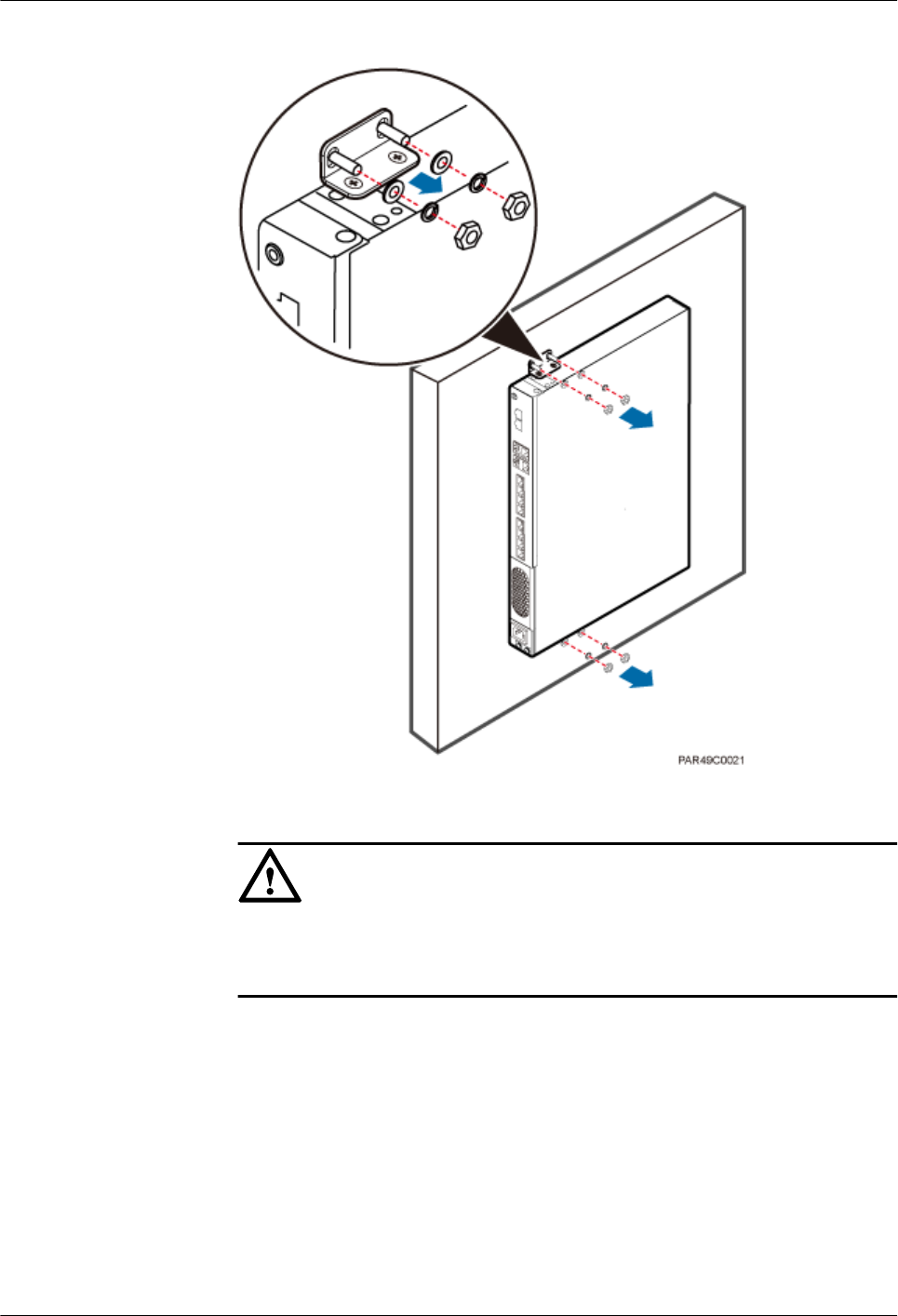
Figure 6-2 Removing the mounting ear
5. Install the new RHUB on a wall. For details, see LampSite Installation Guide.
NOTICE
Take proper ESD protection measures, such as wearing an ESD wrist strap or ESD
gloves to prevent electrostatic damage to the boards, modules, or electronic
components.
6. Connect all the cables to the new RHUB according to the recorded installations.
7. Power on the RHUB by referring to 4.1 Powering On the RHUB.
8. Determine whether the new RHUB is working properly according to the indicator
status on the RHUB. For details about the indicator status, see RHUB Ports and
Indicators in LampSite Hardware Description.
9. Instruct the network operator to run the RST BRD command to reset the RHUB. No
further action is required.
----End
LampSite
Site Maintenance Guide 6 Replacing the RHUB
Issue 02 (2014-05-27) Huawei Proprietary and Confidential
Copyright © Huawei Technologies Co., Ltd.
18

Follow-up Procedure
lPlace the replaced RHUB into an ESD box or bag. Then, place the ESD box or bag into a
foam-padded carton or the packing box of the new optical module.
lRecord the information about the faulty component in the fault card.
lContact the local Huawei office to deal with the faulty component.
LampSite
Site Maintenance Guide 6 Replacing the RHUB
Issue 02 (2014-05-27) Huawei Proprietary and Confidential
Copyright © Huawei Technologies Co., Ltd.
19

7 Replacing an Optical Module
An optical module provides a port for opto-electronic conversion. This enables the transmission
between the RHUB and BBU through the optical fiber. Replacing the optical module requires
removing the optical fibers. This interrupts all the services.
Prerequisites
lThe number and type of faulty optical modules are confirmed, and new optical modules
are available.
lThe new optical modules to be installed must match CPRI rates.
lThe position for installing an optical module and the cable connection are recorded.
lThe following tools and materials are available: an ESD wrist strap or ESD gloves, and an
ESD box or bag.
Context
lThe optical modules are connected to the CPRI0 and CPRI1 ports on the RHUB panel.
lAn optical module or CPRI fiber optic cable cannot be inserted into or removed from this
CPRI port when the power supply is connected.
lReplacing an optical module involves removing an optical fiber and the faulty optical
module, installing a new optical module, connecting the optical fiber to the optical module,
and recovering the links. The operation takes about 10 minutes.
NOTICE
Take proper ESD protection measures, such as wearing an ESD wrist strap or ESD gloves to
prevent electrostatic damage to the boards, modules, or electronic components.
Procedure
Step 1 Wear ESD gloves.
Step 2 Record the optical module and fiber connections.
Step 3 Power off the RHUB according to the instructions in 4.2 Powering Off the RHUB.
LampSite
Site Maintenance Guide 7 Replacing an Optical Module
Issue 02 (2014-05-27) Huawei Proprietary and Confidential
Copyright © Huawei Technologies Co., Ltd.
20
CAUTION
After removing the optical fiber from the optical module, do not look directly at the optical
modules without eye protection.
Step 4 Press the latch on the connector of the optical fiber connector, and remove the connector from
the faulty optical module, use the dust-proof cap to protect the optical fiber, as shown in Figure
7-1.
Figure 7-1 Removing the optical fiber
Step 5 Turn the ring-pull on the faulty optical module outwards. Hold the ring-pull and take the faulty
optical module out of the slot to remove it from the CPRI0 or CPRI1 port.
Step 6 Connect a new optical module to the corresponding CPRI port, as shown in Figure 7-2.
Figure 7-2 Removing the optical module
Step 7 Remove the dust-proof caps from the optical module and optical fiber, and connect the optical
fiber connector to the new optical module.
LampSite
Site Maintenance Guide 7 Replacing an Optical Module
Issue 02 (2014-05-27) Huawei Proprietary and Confidential
Copyright © Huawei Technologies Co., Ltd.
21

Step 8 Power on the RRU according to the instructions in 4.1 Powering On the RHUB.
Step 9 Check whether CPRI signal transmission recovers by observing the CPRI indicator on the RHUB
panel.
If... Then...
The CPRI indicator is green CPRI signal transmission recovers and the
optical fiber replacement is successful.
The CPRI indicator is red or in another color CPRI signal transmission is abnormal. Check
whether the optical fiber and optical module
are securely installed.
Step 10 Take off the ESD gloves and pack up all the tools.
----End
Follow-up Procedure
lPlace the replaced optical module into an ESD box or bag. Then, place the ESD box or bag
into a foam-padded carton or the packing box of the new optical module.
lRecord the information about the faulty component in the fault card.
lContact the local Huawei office to deal with the faulty component.
LampSite
Site Maintenance Guide 7 Replacing an Optical Module
Issue 02 (2014-05-27) Huawei Proprietary and Confidential
Copyright © Huawei Technologies Co., Ltd.
22
8 Replacing the RF Daughter Board
This section describes the procedures for replacing the RF daughter board of the pRRU. A pRRU
can have two transmission ports or three transmission ports, requiring the same installation
operations. This section uses the pRRU with three transmission ports as an example. Replacing
an RF daughter board interrupts all the services carried on the pRRU.
Prerequisites
The replacement takes approximately 5 minutes.
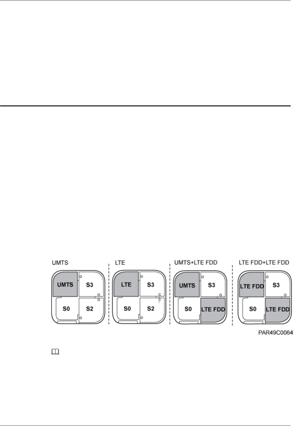
Context
The preferred slot for an RF daughter board depends on the mode of the RF daughter board.
Figure 8-1 shows the slot for installing the RF daughter boards.
Figure 8-1 Slot for installing the RF daughter boards
NOTE
lUnless otherwise specified, LTE mode in this document refers to LTE TDD and LTE FDD.
lThe procedures for replacing an RF daughter board in different slots on the pRRU are the same. The
following section uses the procedures for replacing an RF daughter board in slot S1 as an example.
Procedure
Step 1 Instruct the network operator to block the pRRU.
LampSite
Site Maintenance Guide 8 Replacing the RF Daughter Board
Issue 02 (2014-05-27) Huawei Proprietary and Confidential
Copyright © Huawei Technologies Co., Ltd.
23
lOn the UMTS side, log in to the LMT and run the BLK BRD command to block the RF
daughter board.
lOn the LTE side, log in to the LMT and run the BLK BRD command to block the RF daughter
board.
CAUTION
A pRRU that has just been powered off has afterheat. Take scald-proof measures when removing
the modules.
Step 2 Power off the pRRU by referring to 5.2 Powering Off the pRRU.
Step 3 Wear ESD gloves.
NOTICE
Take proper ESD protection measures. For example, wear ESD gloves to prevent electrostatic
damage to the boards, modules, or electronic components.
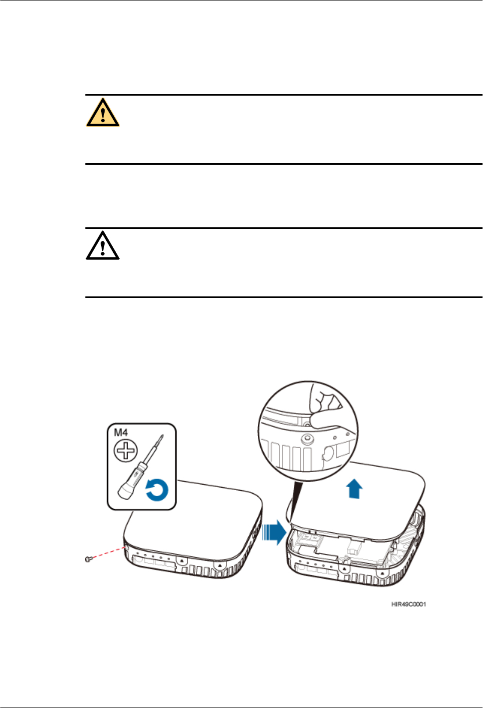
Step 4 Use the M4 Phillips screwdriver to loosen the Phillips screw on the pRRU housing. Wrench and
remove the housing from the installation position of the Phillips screw hole, as shown in Figure
8-2.
Figure 8-2 Removing the pRRU housing
LampSite
Site Maintenance Guide 8 Replacing the RF Daughter Board
Issue 02 (2014-05-27) Huawei Proprietary and Confidential
Copyright © Huawei Technologies Co., Ltd.
24
NOTE
lThe pRRU housing and the RF daughter board can be secured using either Phillips screws or protection
screws, requiring the same installation operations. This section uses Phillips screws as an example to
describe the installation operations.
lKeep the Phillips screw secure for future use.
Step 5 Remove the RF daughter board installed in slot S1.
NOTICE
Hold the RF daughter board tightly when pulling the handle to prevent the RF daughter board
from falling.
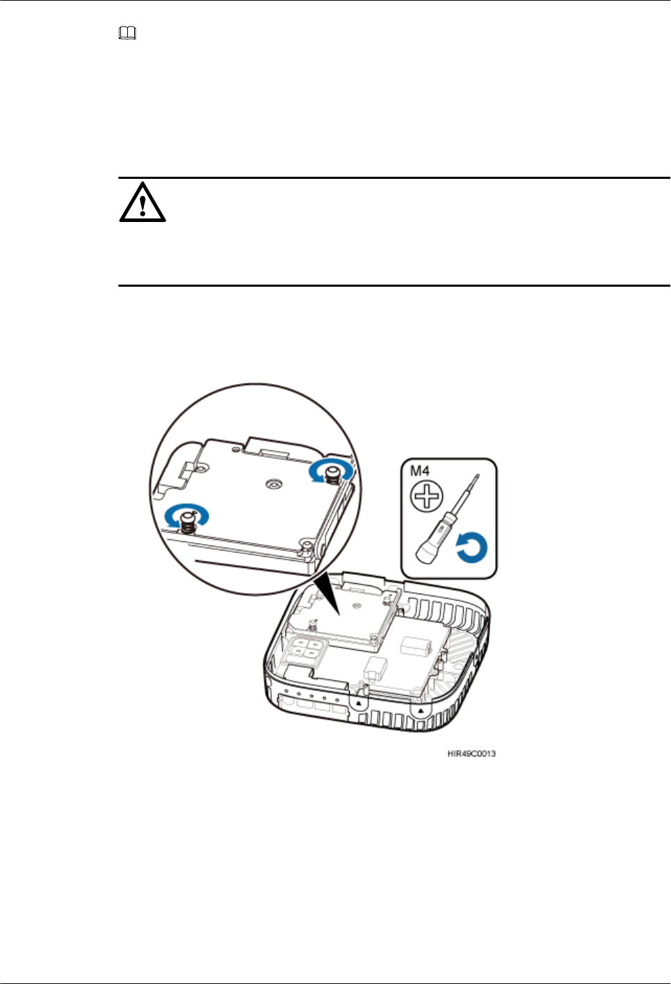
1. Use the M4 Phillips screwdriver to loosen the Phillips screws on the RF daughter board in
slot S1, as shown in Figure 8-3.
Figure 8-3 Loosen the Phillips screws
2. Use the left hand to hold the RF daughter board and the right hand to hold the right handle
of the RF daughter board to remove the RF daughter board and put it into an ESD box or
bag, as shown in Figure 8-4.
LampSite
Site Maintenance Guide 8 Replacing the RF Daughter Board
Issue 02 (2014-05-27) Huawei Proprietary and Confidential
Copyright © Huawei Technologies Co., Ltd.
25

Figure 8-4 Removing the RF daughter board installed in slot S1
Step 6 Install a new RF daughter board in slot S1.
Level the handles of an RF daughter board of the required mode, and insert the handles separately
in the two dowels of slot S1, and use the M4 Phillips screwdriver to tighten the Phillips screws
on the RF daughter board with a torque of 1.4 N•m, as shown in Figure 8-5.
Figure 8-5 Installing the RF daughter board in slot S1
Step 7 Remove the SN label and mode label on the surface of the RF daughter board, as shown in
Figure 8-6.
LampSite
Site Maintenance Guide 8 Replacing the RF Daughter Board
Issue 02 (2014-05-27) Huawei Proprietary and Confidential
Copyright © Huawei Technologies Co., Ltd.
26
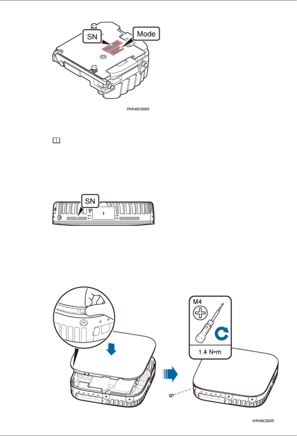
Figure 8-6 Removing the SN label and mode label
Step 8 Attach the removed SN label to the corresponding position for S1 label on the nameplate side
of the pRRU housing, as shown in Figure 8-7.
NOTE
lIf an SN label has been attached to the position for S1 label, remove this label first.
lThe RF daughter board replacement described herein does not involve any mode change. Therefore,
the removed mode label can be discarded
Figure 8-7 Attaching the SN label
Step 9 Close the pRRU housing and tamp each side of the housing until a click is heard. Ensure that
the groove gaps between the front and back housings are evenly distributed. Use the M4 Phillips
screwdriver to tighten the Phillips screw on the housing with a torque of 1.4 N•m, as shown in
Figure 8-8.
Figure 8-8 Installing the pRRU housing
LampSite
Site Maintenance Guide 8 Replacing the RF Daughter Board
Issue 02 (2014-05-27) Huawei Proprietary and Confidential
Copyright © Huawei Technologies Co., Ltd.
27

NOTE
The Phillips screw is the one removed and kept in Step 4.
Step 10 Power on the pRRU by referring to 5.1 Powering On the pRRU.
Step 11 Instruct the network operator to unblock the pRRU.
lOn the UMTS side, log in to the NodeB LMT and run the UBL BRD command to unblock
the RF daughter board of the pRRU.
lOn the LTE side, log in to the eNodeB LMT and run the UBL BRD command to unblock
the RF daughter board of the pRRU.
Step 12 Take off the ESD gloves and pack up all the tools.
----End
Follow-up Procedure
lPlace the replaced RF daughter board into an ESD box or bag. Then, place the ESD box or
bag into a foam-padded carton or the packing box of the new optical module.
lRecord the information about the faulty component in the fault card.
lContact the local Huawei office to deal with the faulty component.
LampSite
Site Maintenance Guide 8 Replacing the RF Daughter Board
Issue 02 (2014-05-27) Huawei Proprietary and Confidential
Copyright © Huawei Technologies Co., Ltd.
28
9 Replacing the Wi-Fi Daughter Board
This section describes the procedures for replacing the Wi-Fi daughter board, which applies only
to a pRRU with three transmission ports.Replacing an Wi-Fi daughter board interrupts all the
services carried on the pRRU.
Prerequisites
The replacement takes approximately 5 minutes.
Context
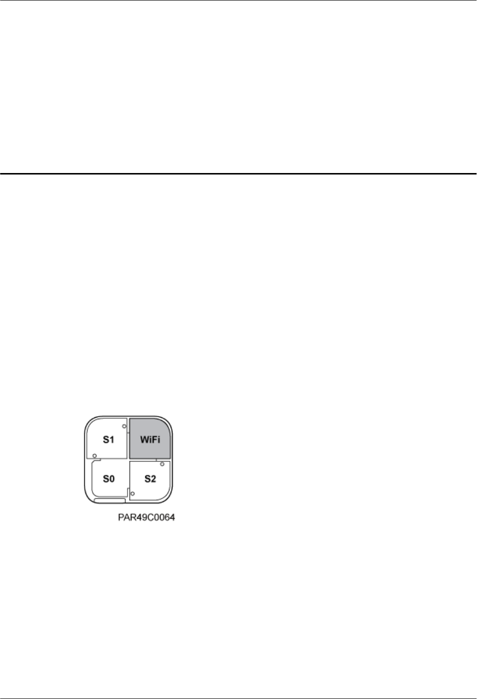
On a pRRU with three transmission ports, a Wi-Fi daughter board can be installed only in slot
S3, as shown in Figure 9-1.
Figure 9-1 Slot for installing the Wi-Fi daughter board
Procedure
Step 1 Instruct the network operator to block the pRRU.
lOn the UMTS side, log in to the LMT and run the BLK BRD command to block the RF
daughter board.
lOn the LTE side, log in to the LMT and run the BLK BRD command to block the RF daughter
board.
Step 2 Ask the AC administrator to change on the AC the MAC address of the corresponding Wi-Fi
daughter board.
LampSite
Site Maintenance Guide 9 Replacing the Wi-Fi Daughter Board
Issue 02 (2014-05-27) Huawei Proprietary and Confidential
Copyright © Huawei Technologies Co., Ltd.
29
CAUTION
A pRRU that has just been powered off has afterheat. Take scald-proof measures when removing
the Wi-Fi daughter board.
Step 3 Power off the pRRU by referring to 5.2 Powering Off the pRRU.
Step 4 Wear ESD gloves.
NOTICE
Take proper ESD protection measures. For example, wear ESD gloves to prevent electrostatic
damage to the boards, modules, or electronic components.
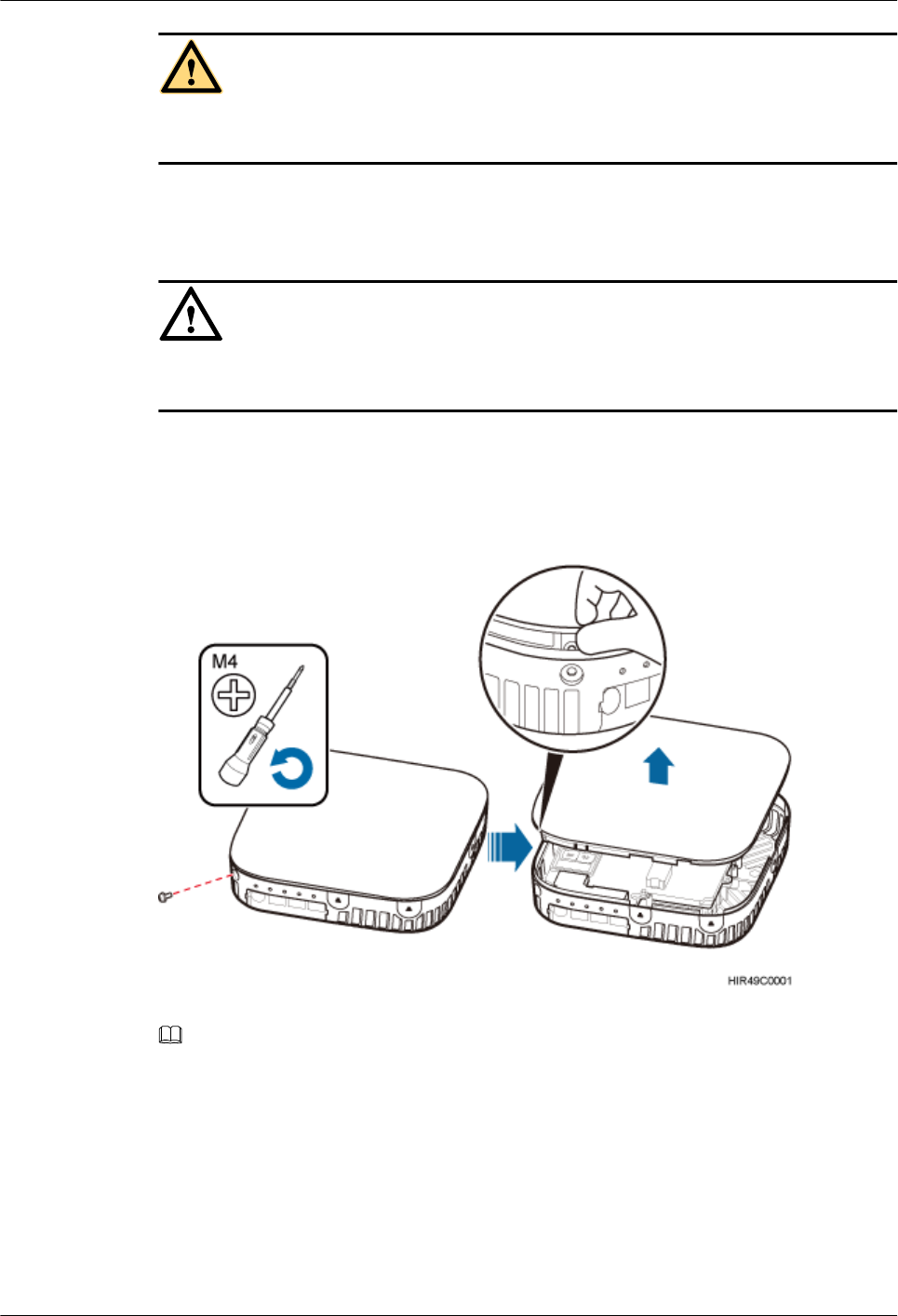
Step 5 Use the M4 Phillips screwdriver to loosen the Phillips screw on the pRRU housing. Wrench and
remove the housing from the installation position of the Phillips screw hole, as shown in Figure
9-2.
Figure 9-2 Removing the pRRU housing
NOTE
lThe pRRU housing and the Wi-Fi daughter board can be secured using Phillips screws or protection
screws, requiring the same installation operations. This section uses Phillips screws as an example.
lKeep the protection screw secure for future use.
Step 6 Remove the Wi-Fi daughter board installed in slot S1.
LampSite
Site Maintenance Guide 9 Replacing the Wi-Fi Daughter Board
Issue 02 (2014-05-27) Huawei Proprietary and Confidential
Copyright © Huawei Technologies Co., Ltd.
30
NOTICE
Hold the Wi-Fi daughter board tightly when pulling the handle to prevent the Wi-Fi daughter
board from falling.
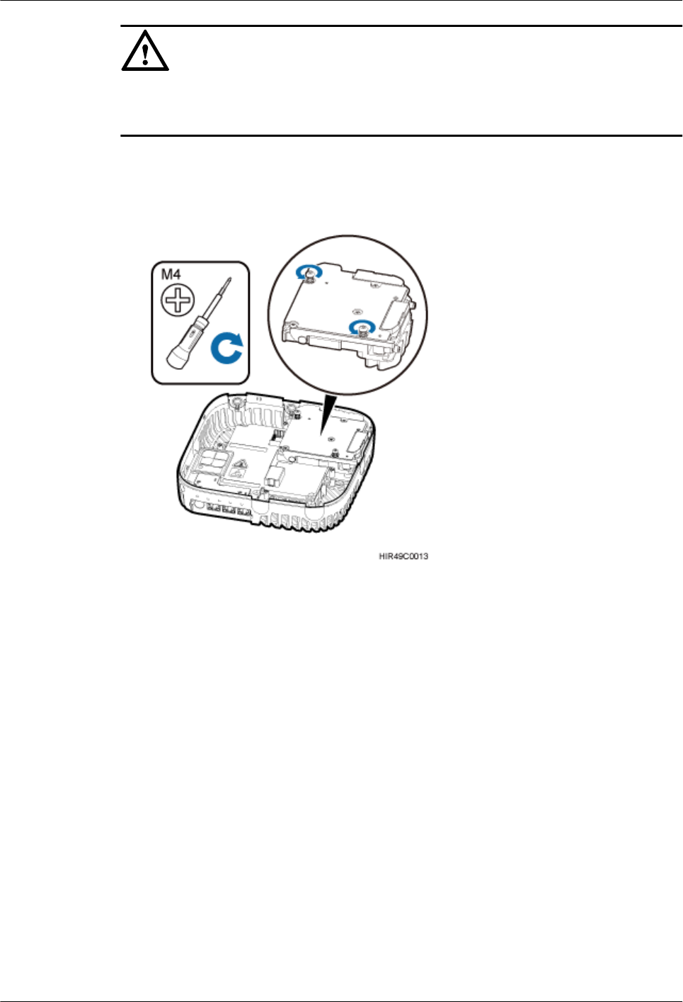
1. Use the M4 Phillips screwdriver to loosen the Phillips screws on the Wi-Fi daughter board
in slot S3, as shown in Figure 9-3.
Figure 9-3 Loosen the four fastening screws
2. Use the left hand to hold the Wi-Fi daughter board and the right hand to hold the right
handle of the Wi-Fi daughter board to remove the Wi-Fi daughter board and put it into an
ESD box or bag, as shown in Figure 9-4.
LampSite
Site Maintenance Guide 9 Replacing the Wi-Fi Daughter Board
Issue 02 (2014-05-27) Huawei Proprietary and Confidential
Copyright © Huawei Technologies Co., Ltd.
31
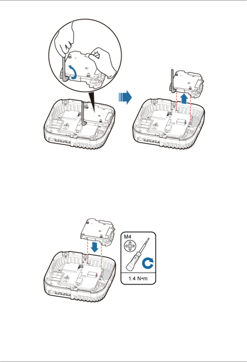
Figure 9-4 Removing the Wi-Fi daughter board installed in slot S3
Step 7 Install a new Wi-Fi daughter board in slot S3.
Level the handles of a Wi-Fi daughter board of the required mode, and insert the handles
separately in the two dowels of slot S3, and use the M4 Phillips screwdriver to tighten the Phillips
screws on the Wi-Fi daughter board with a torque of 1.4 N•m, as shown in Figure 9-5.
Figure 9-5 Installing the Wi-Fi daughter board in slot S1
Step 8 Remove the SN label and WIFI MAC labels on the surface of the Wi-Fi daughter board, as
shown in Figure 9-6. Keep the labels secure.
LampSite
Site Maintenance Guide 9 Replacing the Wi-Fi Daughter Board
Issue 02 (2014-05-27) Huawei Proprietary and Confidential
Copyright © Huawei Technologies Co., Ltd.
32
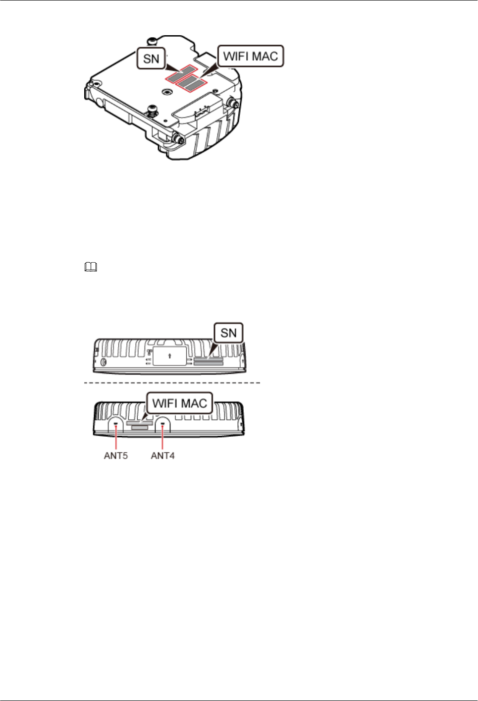
Figure 9-6 Removing the SN label and WIFI MAC labels
Step 9 Attach one WIFI MAC label to MAC Collection Template and report the WIFI MAC
information to the commissioning personnel.
Step 10 Attach the removed SN label to the corresponding position for S3 label on the nameplate side
of the pRRU housing and the other WIFI MAC label to a position (for the label of slot S3 on
the side of the pRRU housing) between antenna ports ANT4 and ANT5, as shown in Figure
9-7.
NOTE
If an SN label has been attached to the position for S3 label, remove this label first.
Figure 9-7 Attaching the SN label and WIFI MAC label
Step 11 Close the pRRU housing and tamp each side of the housing until a click is heard. Ensure that
the groove gaps between the front and back housings are evenly distributed. Use the M4 Phillips
screwdriver to tighten the Phillips screw on the housing with a torque of 1.4 N•m, as shown in
Figure 9-8.
LampSite
Site Maintenance Guide 9 Replacing the Wi-Fi Daughter Board
Issue 02 (2014-05-27) Huawei Proprietary and Confidential
Copyright © Huawei Technologies Co., Ltd.
33
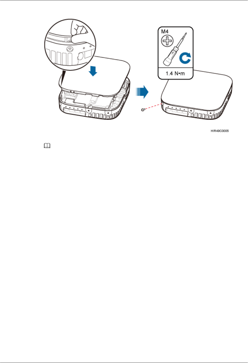
Figure 9-8 Installing the pRRU housing
NOTE
The Phillips screw is the one removed and kept in Step 5.
Step 12 Power on the pRRU by referring to 5.1 Powering On the pRRU.
Step 13 Instruct the network operator to unblock the pRRU.
lOn the UMTS side, log in to the NodeB LMT and run the UBL BRD command to unblock
the RF daughter board of the pRRU.
lOn the LTE side, log in to the eNodeB LMT and run the UBL BRD command to unblock
the RF daughter board of the pRRU.
Step 14 Take off the ESD gloves and pack up all the tools.
----End
LampSite
Site Maintenance Guide 9 Replacing the Wi-Fi Daughter Board
Issue 02 (2014-05-27) Huawei Proprietary and Confidential
Copyright © Huawei Technologies Co., Ltd.
34
10 Replacing the pDock Mother Board
This section describes the procedure for replacing the pDock mother board. Replacing the pDock
mother board of a pRRU will interrupt all services carried on the pRRU. A pDock mother board
can have two transmission ports or three transmission ports, requiring the same installation
operations. This section uses the pDock mother board with three transmission ports as an
example.
Prerequisites
The process takes approximately 20 minutes.
Procedure
Step 1 Instruct the network operator to block the pRRU.
lOn the UMTS side, log in to the LMT and run the BLK BRD command to block the RF
daughter board.
lOn the LTE side, log in to the LMT and run the BLK BRD command to block the RF daughter
board.
CAUTION
A pRRU that has just been powered off is till very hot on the surface. Take scald-proof measures
when removing the modules.
Step 2 Power off the pRRU by referring to 5.2 Powering Off the pRRU.
Step 3 Put on ESD gloves.
NOTICE
Take proper ESD protection measures, for example, wear ESD gloves, to prevent electrostatic
damage to the boards, modules, or electronic components.
LampSite
Site Maintenance Guide 10 Replacing the pDock Mother Board
Issue 02 (2014-05-27) Huawei Proprietary and Confidential
Copyright © Huawei Technologies Co., Ltd.
35
Step 4 Record connection positions of all pRRU cables, and then remove the cables.
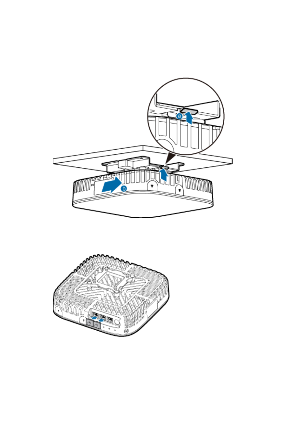
Step 5 Removing the pRRU. Hold the pRRU case in one hand and pull the hoist clamp on the mounting
bracket with the other hand, as shown in step a in Figure 10-1. Then, remove the mounting
bracket from the pRRU, as shown in step b in Figure 10-1.
Figure 10-1 Removing the pRRU
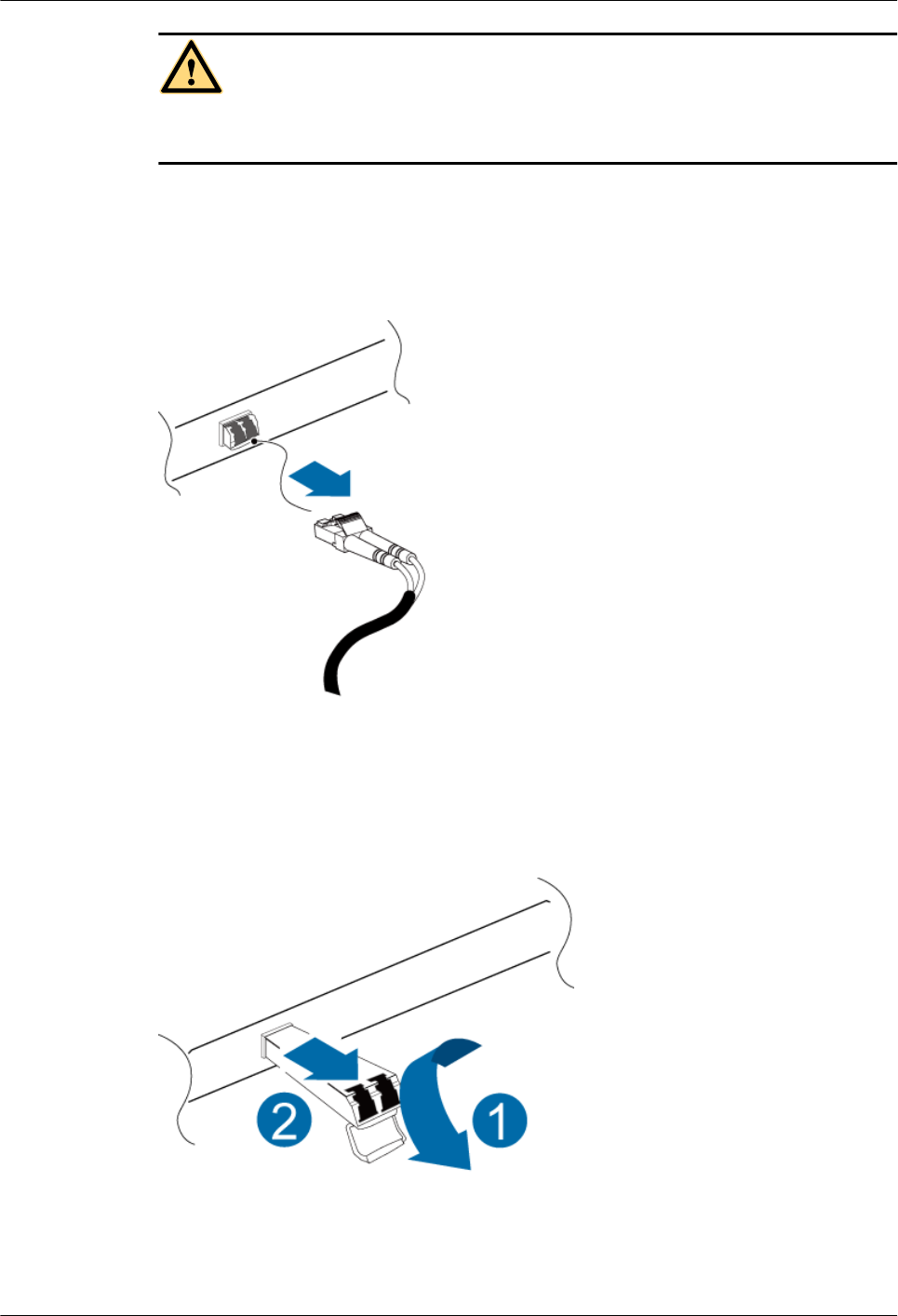
Step 6 Optional: Remove the rubber plug from the Ethernet port, as shown in Figure 10-2.
Figure 10-2 Removing the rubber plug from the Ethernet port
Step 7 Remove the four rubber plugs from holes of the installation support, as shown in Figure 10-3.
LampSite
Site Maintenance Guide 10 Replacing the pDock Mother Board
Issue 02 (2014-05-27) Huawei Proprietary and Confidential
Copyright © Huawei Technologies Co., Ltd.
36
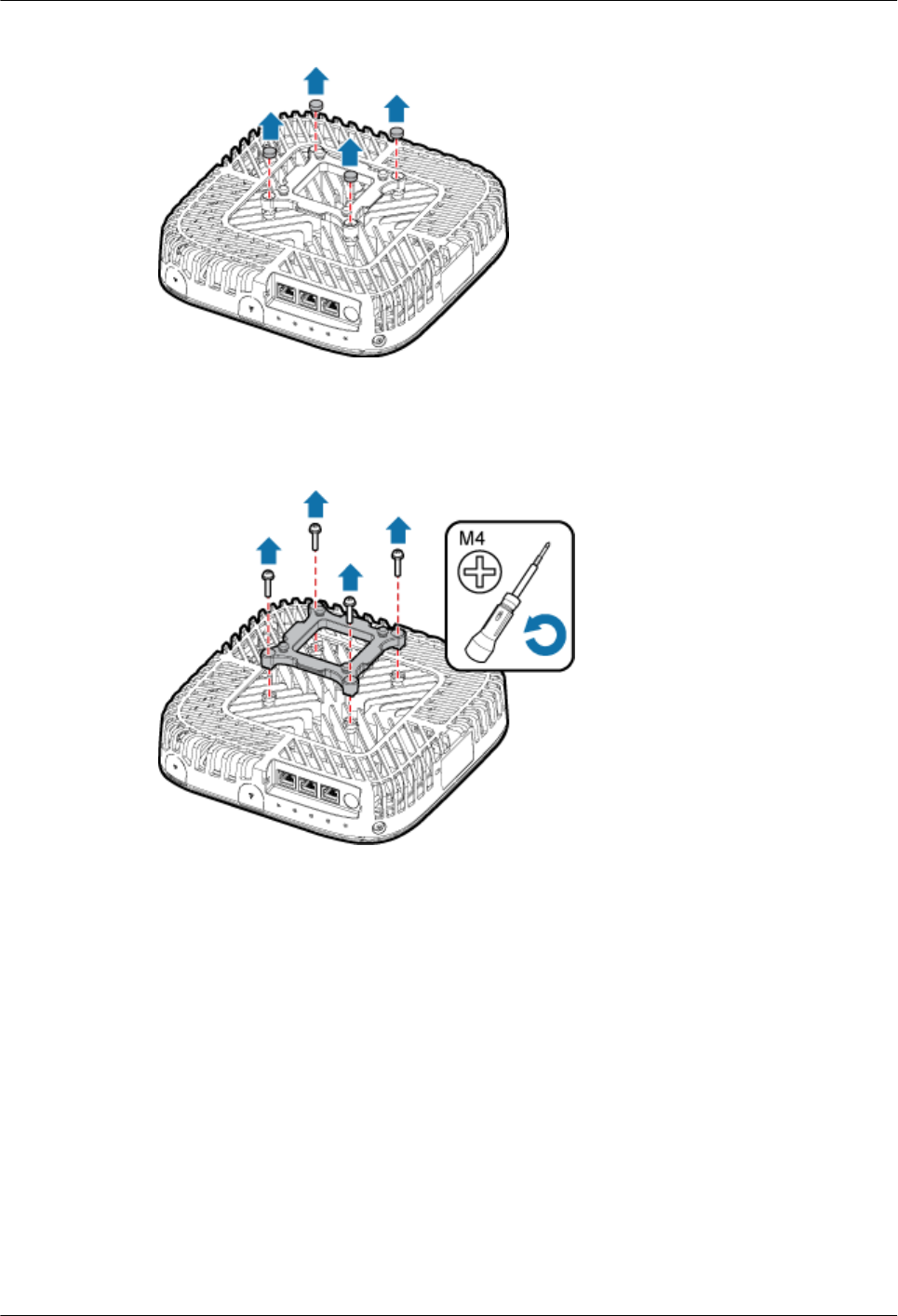
Figure 10-3 Removing rubber plugs from the installation support
Step 8 Use an M4 Phillips screwdriver to loosen the Phillips screws for the installation support, and
remove the support, as shown in Figure 10-4.
Figure 10-4 Removing the installation support
Step 9 Use an M4 Phillips screwdriver to loosen the Phillips screw on the pRRU housing, and remove
the housing, as shown in Figure 10-5.
LampSite
Site Maintenance Guide 10 Replacing the pDock Mother Board
Issue 02 (2014-05-27) Huawei Proprietary and Confidential
Copyright © Huawei Technologies Co., Ltd.
37
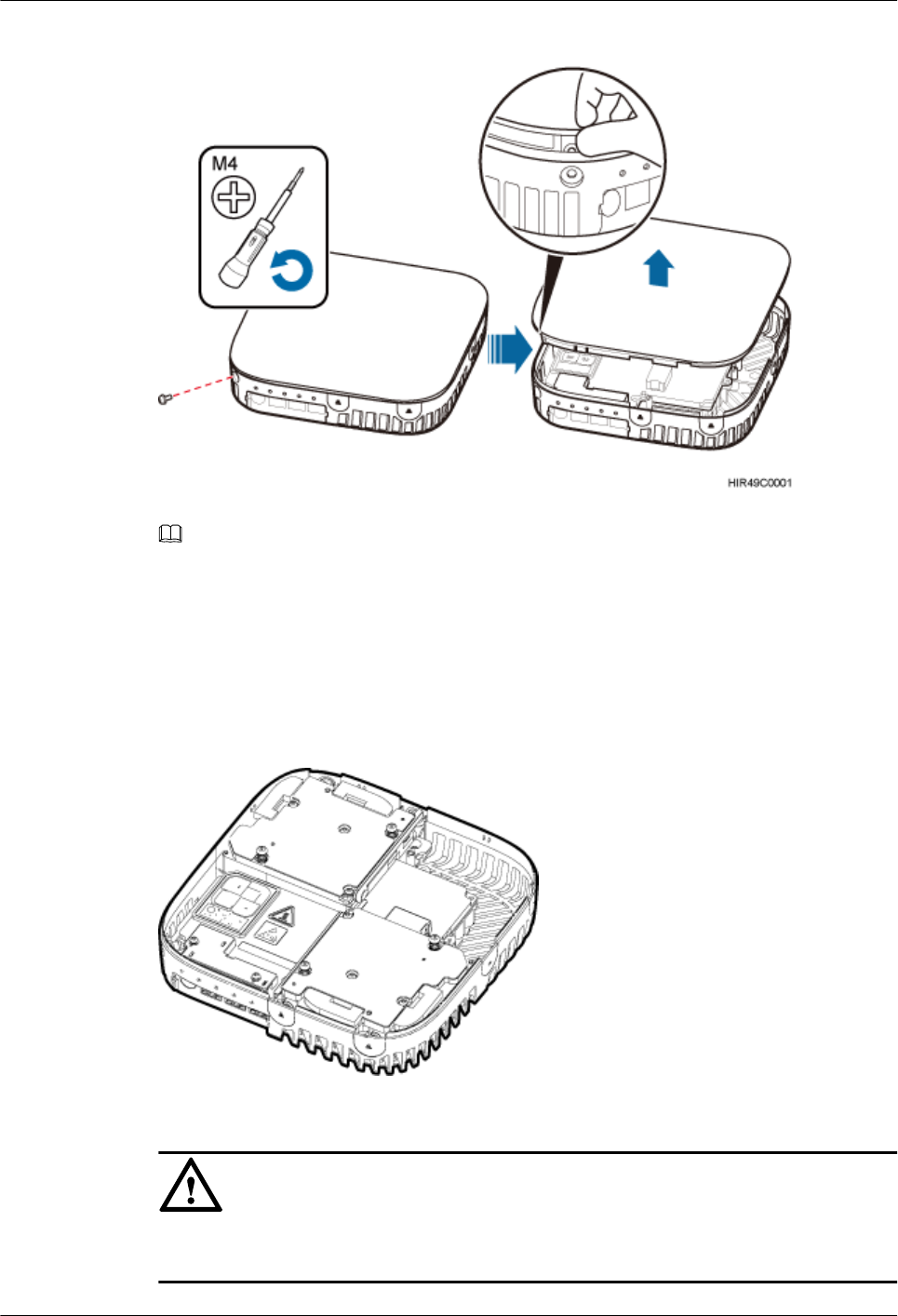
Figure 10-5 Removing the pRRU housing
NOTE
lThe pRRU housing and the RF daughter board can be secured using either Phillips screws or protection
screws, requiring the same installation operations. This section uses Phillips screws as an example to
describe the installation operations.
lKeep the Phillips screw secure for future use.
Step 10 Record positions of the RF daughter boards on the pRRU mother board, as shown in Figure
10-6. The following section assumes that the pRRU has two RF daughter boards.
Figure 10-6 Recording the installation positions of RF daughter boards
Step 11 Remove the RF daughter board in slot S1 and that in slot S2 in the same way.
NOTICE
Hold the RF daughter board tightly when pulling the handle to prevent the RF daughter board
from falling.
LampSite
Site Maintenance Guide 10 Replacing the pDock Mother Board
Issue 02 (2014-05-27) Huawei Proprietary and Confidential
Copyright © Huawei Technologies Co., Ltd.
38
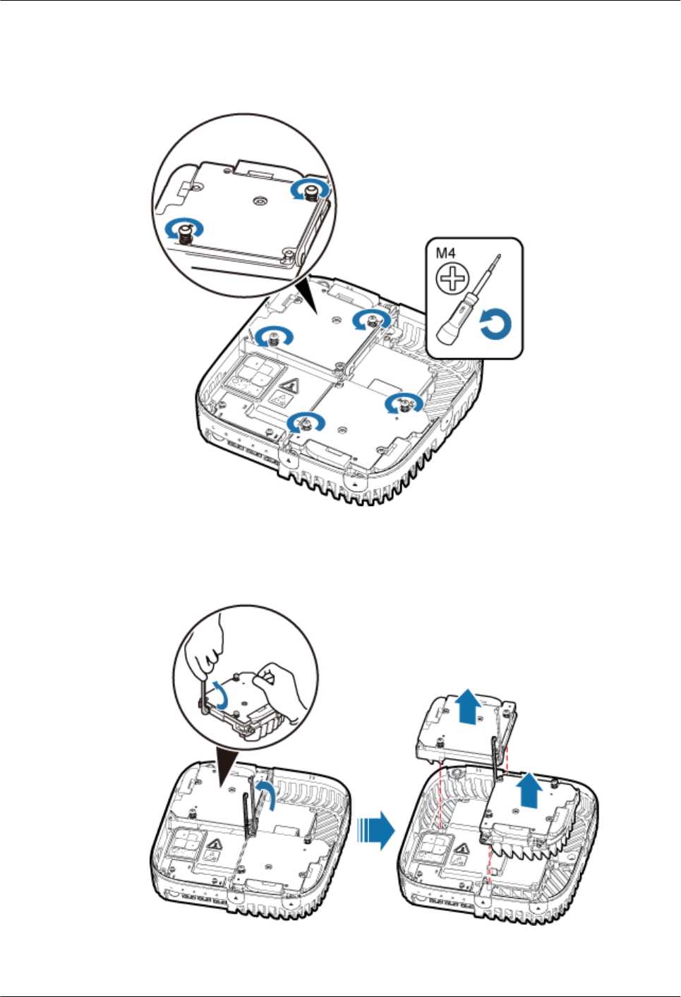
1. Use an M4 Phillips screwdriver to loosen the Phillips screws on the RF daughter board, as
shown in Figure 10-7.
Figure 10-7 Removing Phillips screws
2. Hold the RF daughter board with one hand and pull its handle with another hand to remove
the board, and place the board in an ESD bag, as shown in Figure 10-8.
Figure 10-8 Removing the RF daughter board in slot1 and slot2
LampSite
Site Maintenance Guide 10 Replacing the pDock Mother Board
Issue 02 (2014-05-27) Huawei Proprietary and Confidential
Copyright © Huawei Technologies Co., Ltd.
39

Step 12 Use an M3 Phillips screwdriver to loosen the two fastening screws of the light pipe, and remove
the light pipe, as shown in Figure 10-9.
Figure 10-9 Removing the light pipe
Step 13 Use the M3 Phillips screwdriver to loosen the four fastening screws of the pDock mother board,
and remove the pDock mother board, as shown in Figure 10-10.
Figure 10-10 Removing the pDock mother board
Step 14 Install a new pDock mother board, and use the M3 Phillips screwdriver to tighten the four
fastening screws to 0.8 N•m, as shown in Figure 10-11.
LampSite
Site Maintenance Guide 10 Replacing the pDock Mother Board
Issue 02 (2014-05-27) Huawei Proprietary and Confidential
Copyright © Huawei Technologies Co., Ltd.
40
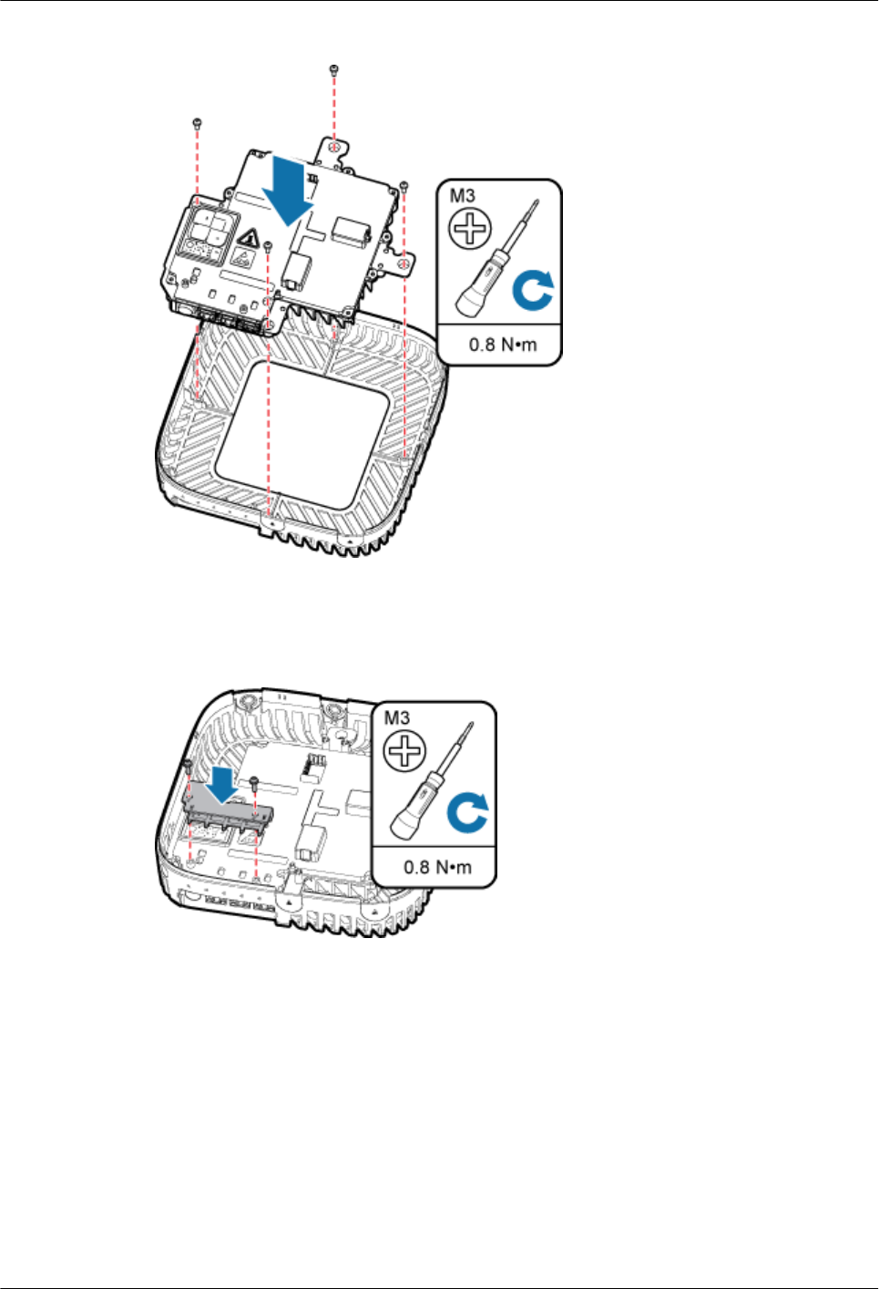
Figure 10-11 Installing a new pDock mother board
Step 15 Install the light pipe, and use the M3 Phillips screwdriver to tighten the two fastening screws to
0.8 N•m, as shown in Figure 10-12.
Figure 10-12 Installing the light pipe
Step 16 Install the RF daughter boards in slots S1 and S2, and use the M4 Phillips screwdriver to tighten
the two fastening screws always carried on each daughter board to 1.4 N•m, as shown in Figure
10-13.
LampSite
Site Maintenance Guide 10 Replacing the pDock Mother Board
Issue 02 (2014-05-27) Huawei Proprietary and Confidential
Copyright © Huawei Technologies Co., Ltd.
41
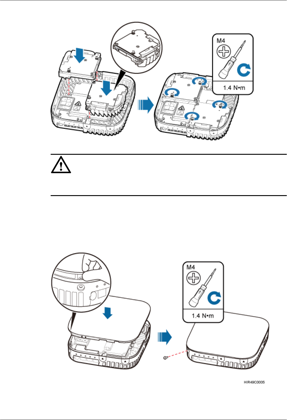
Figure 10-13 Installing the RF daughter boards
NOTICE
The installation positions of the RF daughter boards must be consistent before and after the
replacement.
Step 17 Close the pRRU housing and tamp each side of the housing until a click is heard. Ensure that
the groove gaps between the front and back housings are evenly distributed. Then, use the M4
Phillips screwdriver to tighten the Phillips screw on the housing to 1.4 N•m, as shown in Figure
10-14.
Figure 10-14 Installing the pRRU housing
LampSite
Site Maintenance Guide 10 Replacing the pDock Mother Board
Issue 02 (2014-05-27) Huawei Proprietary and Confidential
Copyright © Huawei Technologies Co., Ltd.
42
NOTE
The Phillips screw is the one removed and kept in Step 9.
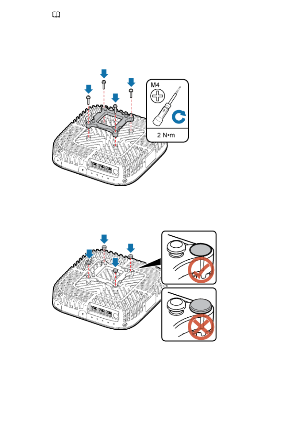
Step 18 Assemble the installation support, and use the M4 Phillips screwdriver to tighten the four
fastening screws to 2 N•m, as shown in Figure 10-15.
Figure 10-15 Assembling the installation support
Step 19 Neatly insert four rubber plugs into the holes of the installation support, as shown in Figure
10-16.
Figure 10-16 Assembling the installation support
Step 20 Connect all the cables to the pRRU according to the recorded installations.
Step 21 Optional: Insert the rubber plug into the Ethernet port, as shown in Figure 10-17.
LampSite
Site Maintenance Guide 10 Replacing the pDock Mother Board
Issue 02 (2014-05-27) Huawei Proprietary and Confidential
Copyright © Huawei Technologies Co., Ltd.
43
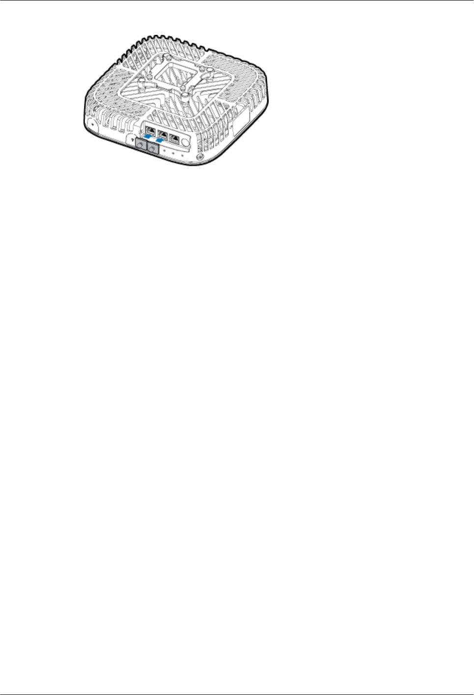
Figure 10-17 Assembling the installation support
Step 22 Install the pRRU. The installation must be based on different scenarios. For details, see LampSite
Installation Guide.
Step 23 Power on the pRRU by referring to 5.1 Powering On the pRRU.
Step 24 Instruct the network operator to unblock the pRRU.
lOn the UMTS side, log in to the NodeB LMT and run the UBL BRD command to unblock
the RF daughter board.
lOn the LTE side, log in to the eNodeB LMT and run the UBL BRD command to unblock
the RF daughter board.
Step 25 Take off the ESD gloves and pack up all the tools.
----End
Follow-up Procedure
lPlace the replaced pDock Mother Board into an ESD box or bag. Then, place the ESD box
or bag into a foam-padded carton or the packing box of the new optical module.
lRecord the information about the faulty component in the fault card.
lContact the local Huawei office to deal with the faulty component.
LampSite
Site Maintenance Guide 10 Replacing the pDock Mother Board
Issue 02 (2014-05-27) Huawei Proprietary and Confidential
Copyright © Huawei Technologies Co., Ltd.
44