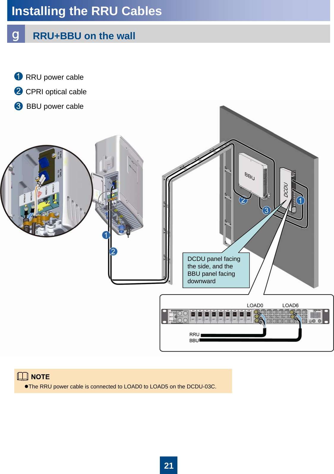
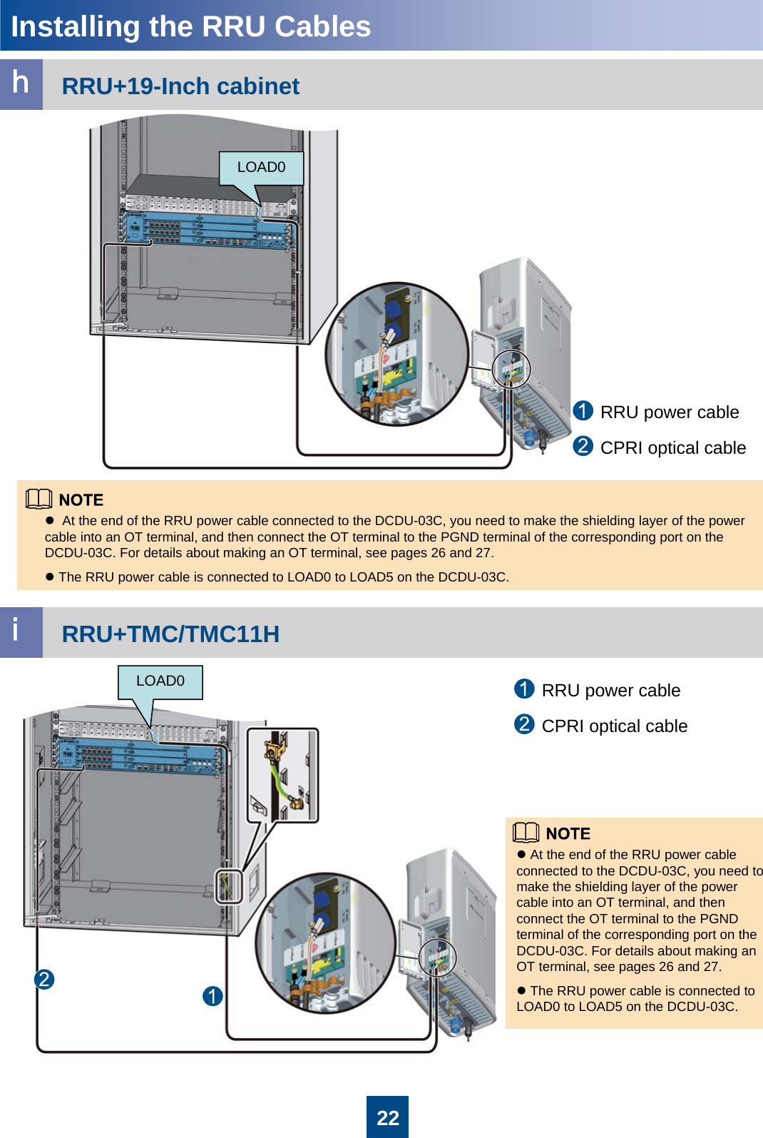
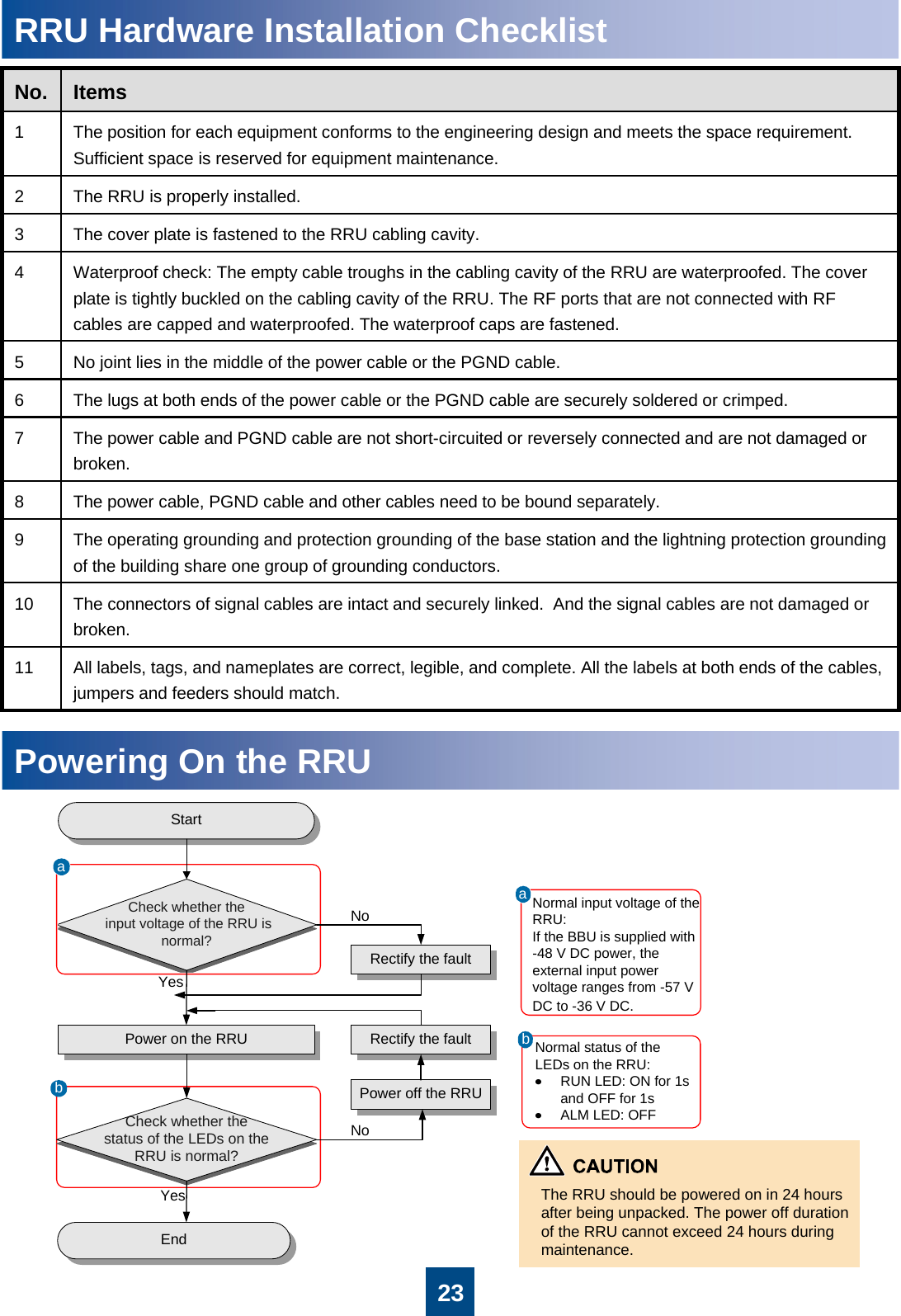
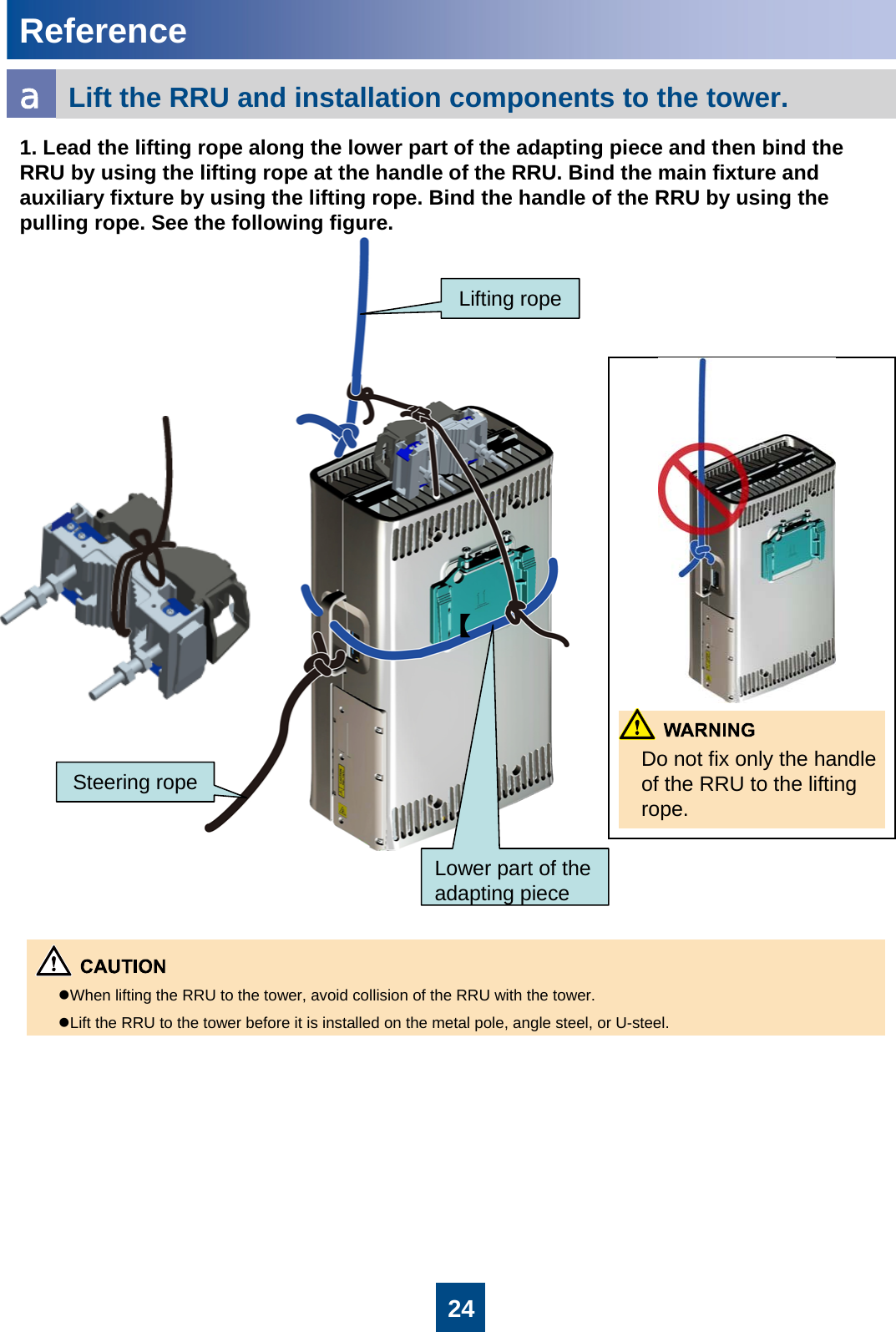
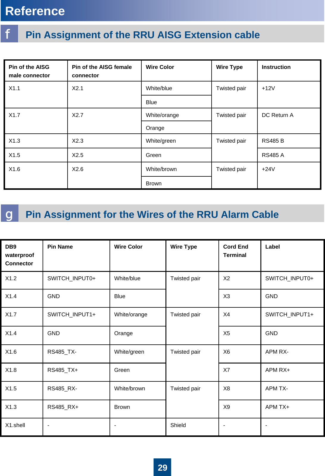
Huawei Technologies RRU3201-2600M Distributed Base Station Remote Radio Unit User Manual Installation Guide
Huawei Technologies Co.,Ltd Distributed Base Station Remote Radio Unit Installation Guide
UserManual.wiki
>
Huawei Technologies
>
RRU3201 2600M User Manual
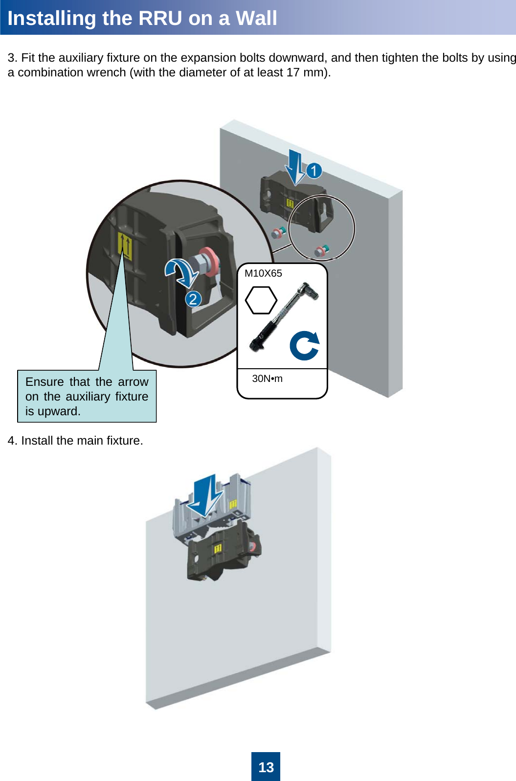
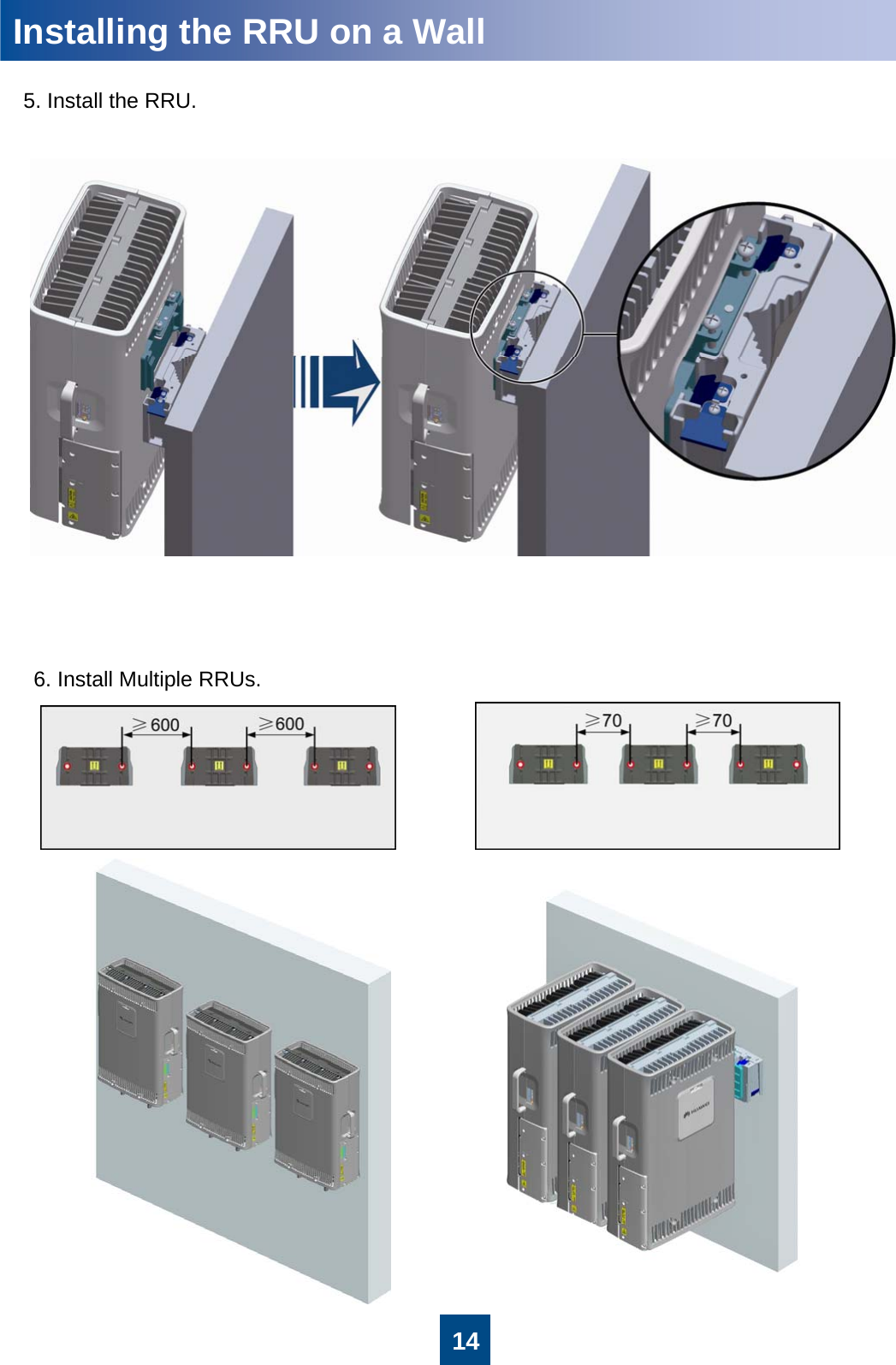
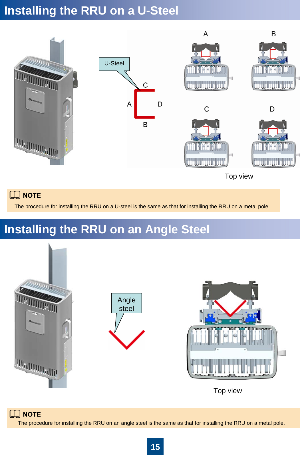
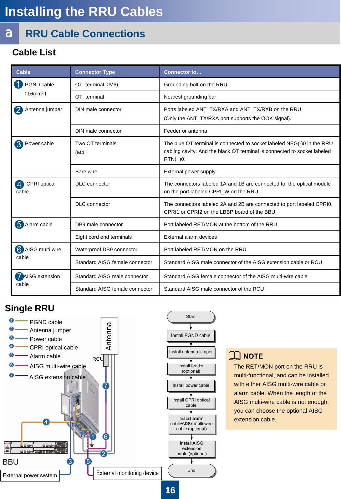
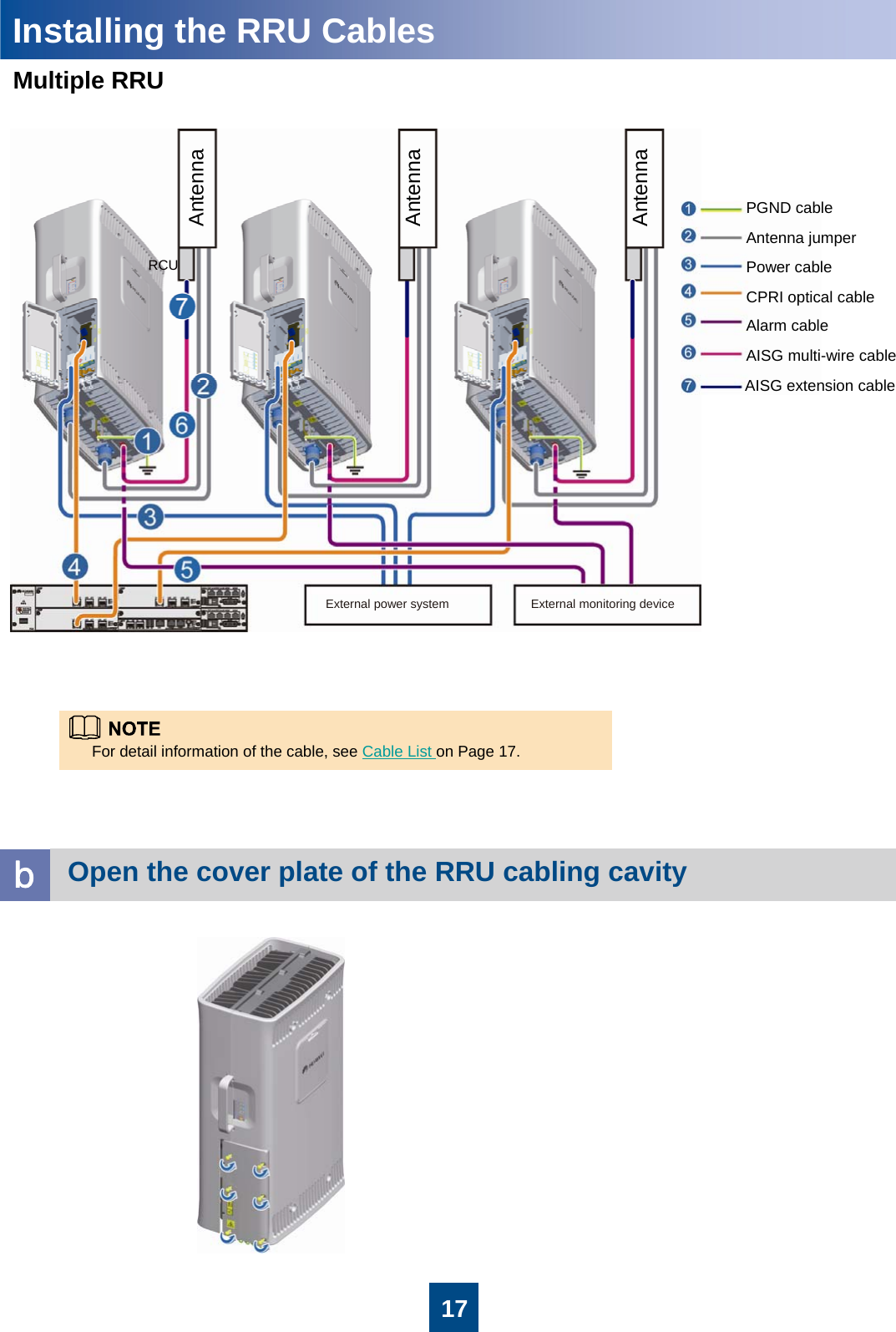
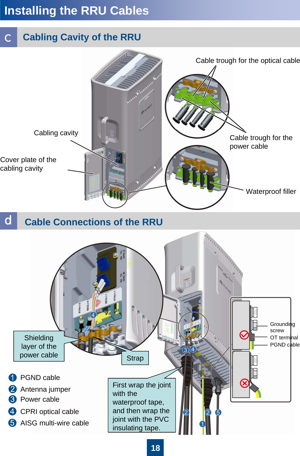
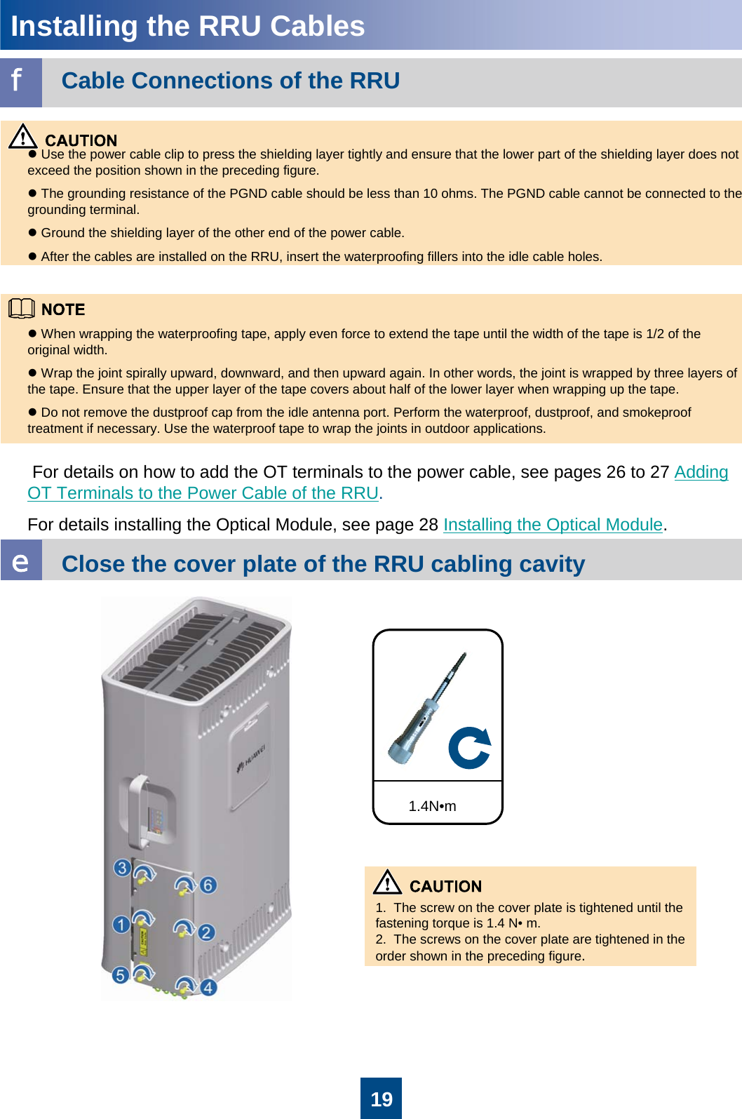
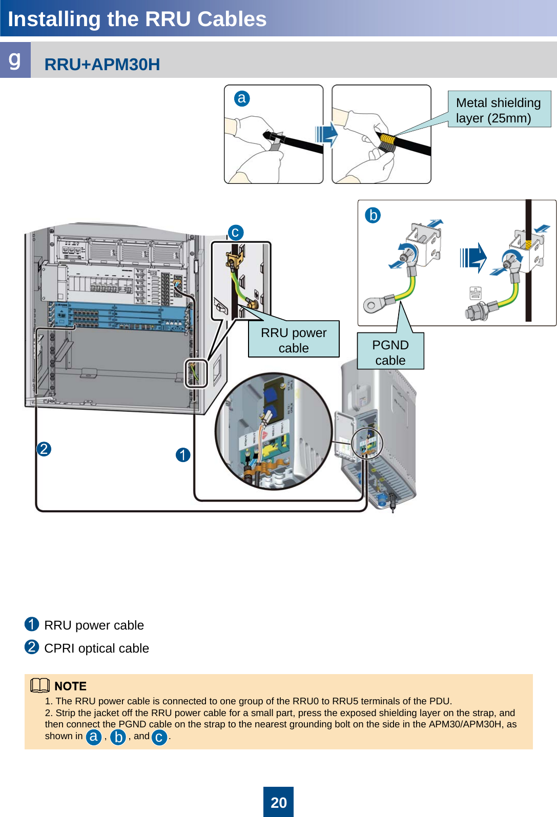
Installation Guide
Navigation menu
Upload a User Manual
Namespaces
Wiki Guide
HTML
PDF
Info
Views
User Manual
Discussion / Help
Navigation