Huawei Technologies RRU3201-2600M Distributed Base Station Remote Radio Unit User Manual Installation Guide
Huawei Technologies Co.,Ltd Distributed Base Station Remote Radio Unit Installation Guide
Installation Guide

HUAWEI TECHNOLOGIES Co., Ltd.
Issue: 01
Part Number:
Date: 2009-08-10
RRU3201 V100R001C01
Installation Guide

1
Safety Information …………………………………………….….……
Installation Tools ………………………………………….…………..
Space Requirements …………………………………….……..…….
Installation Modes …………………………………………………….
Installation Procedure …………………………………….………….
Components Delivered with the RRU ……………………………..
Installing the RRU on a Metal Pole ………………..……………….
Installing the RRU on a Wall ………………………………………..
Installing the RRU on a U-Steel ……………….……….…………..
Installing the RRU on an Angle Steel ……………………………..
Installing the RRU Cables …………………………………………..
RRU Hardware Installation Checklist ……………………………..
Powering On the RRU …………………………………...…………..
Reference ………………………………………………………..……..
Change History …………………………………...…………………..
Contents
Copyright © Huawei Technologies Co., Ltd. 2009. All rights reserved.
2
3
4
5
6
6
7
12
15
15
16
23
23
24
30
2Copyright © Huawei Technologies Co., Ltd. 2009. All rights reserved.
Following All Safety Precautions
Before any operation, read the instructions and precautions in this document carefully to minimize the possibility
of accidents.
The Danger, Caution, and Note items in the documents do not cover all the safety precautions that must be
followed. They only provide the generic safety precautions for operations.
When operating Huawei products and equipment, you must comply with safety precautions and special safety
instructions related to corresponding equipment provided by Huawei. The safety precautions in the document
are related to only Huawei products. Huawei is not liable for any consequence that results from the violation of
universal regulations for safety operations and safety codes on design, production, and equipment use.
Complying with the Local Safety Regulations
When operating the device, comply with the local safety regulations. The safety precautions provided in the
documents are supplementary. You must comply with the local safety regulations.
Qualified Personnel Only
The personnel in charge of installation and maintenance must be trained and master the correct operating
methods and safety precautions before beginning work.
Symbols
Safety of Personnel
• The high voltage power supply provides power for running the system. Direct contact with the high voltage
power supply or contact through damp objects may result in fatal danger.
• Non-standard and improper high voltage operations may result in fire and electric shock.
• In a thunderstorm, do not perform operations on high voltage and AC power supply facilities or on a steel
tower and mast.
• Ground the device before powering on the device. Otherwise, the personnel and device are in danger.
• Power off the device before performing operations on the power supply equipment.
• High power radio-frequency signals are harmful to human body. Before installing or maintaining an antenna
on a steel tower or mast with a large number of transmitter antennas, the operator should coordinate with all
parties to ensure that the transmitter antennas are shut down.
• When handling optical fibers, do not stand close to, or look into the optical fiber outlet with unaided eyes.
• Protect yourself when drilling holes. Flying dust may hurt your eyes or you may inhale the dust.
• Power off the batteries before connecting the cables to the batteries. Otherwise, casualties may occur.
• When working at a height, be cautious about falling objects.
Device Safety
• Check the electrical connection of the device before operation and ensure that the device is reliably grounded.
• The static electricity generated by the human body may damage the electrostatic sensitive components on
the circuit board, such as the large-scale integrated circuit (LIC). Wear an ESD wrist strap or ESD gloves when
performing the operation.
• When working on batteries, take measures to prevent short circuits in the batteries and electrolyte spill/loss.
The electrolyte may erode metal and boards, or even cause rust of the equipment or short circuits in the boards.
• When the equipment is unpacked, it must be powered on in 24 hours. The maximum duration of the power-
off state of the equipment is 24 hours during maintenance.
Safety Information
Indicates a hazard with a high level of risk, which if not avoided,will result in death or
serious injury.
DANGER
WARNING
CAUTION
TIP
NOTE
Indicates a hazard with a medium or low level of risk, which if not avoided, could result
in minor or moderate injury.
Indicates a potentially hazardous situation, which if not avoided,could result in
equipment damage, data loss, performance degradation, or unexpected results.
Indicates a tip that may help you solve a problem or save time.
Provides additional information to emphasize or supplement important points of the
main text.

3
Installation Tools
Adjustable wrench
(with the diameter of at least 32 mm)
Torque screwdriver
Measuring tape
Vacuum cleaner
Wire Stripper
Level
Marker
Multimeter
Claw hammer
ESD gloves
Combination wrench
(21mm~21mm) for pole installation
Power cable crimping tool Cable cutter
Heat gun
Hammer drill
Knife
(17mm~17mm) for pole installation
Flat-head screwdriver (M3 to M6)Phillips screwdriver (M3~M6)
4
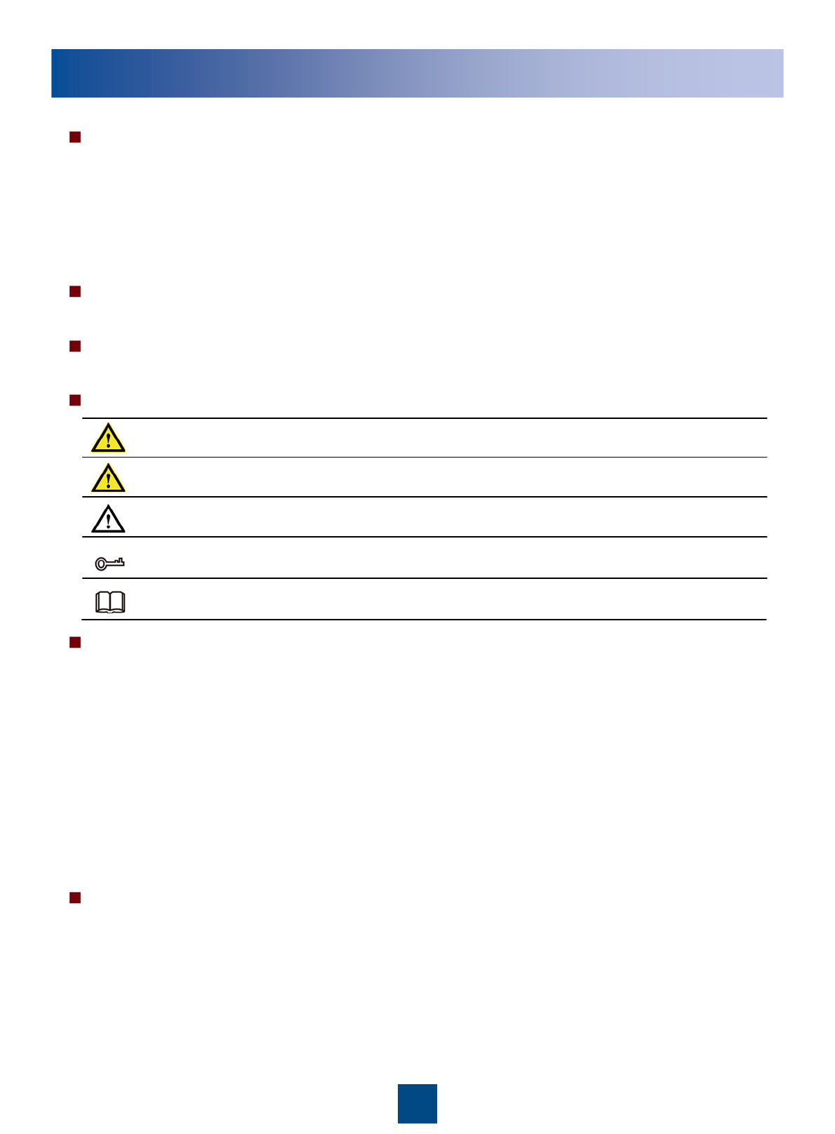
Space Requirements (Unit: mm)
a
bc
d
RRU Dimensions
Recommended Clearance for a
Single RRU Minimum Clearance for a Single
RRU
Recommended Clearance for
Multiple Centralized RRUs eMinimum Clearance for Multiple
Centralized RRUs
≥300
≥300≥600
≥800
≥500
200
300
400
100
600
5
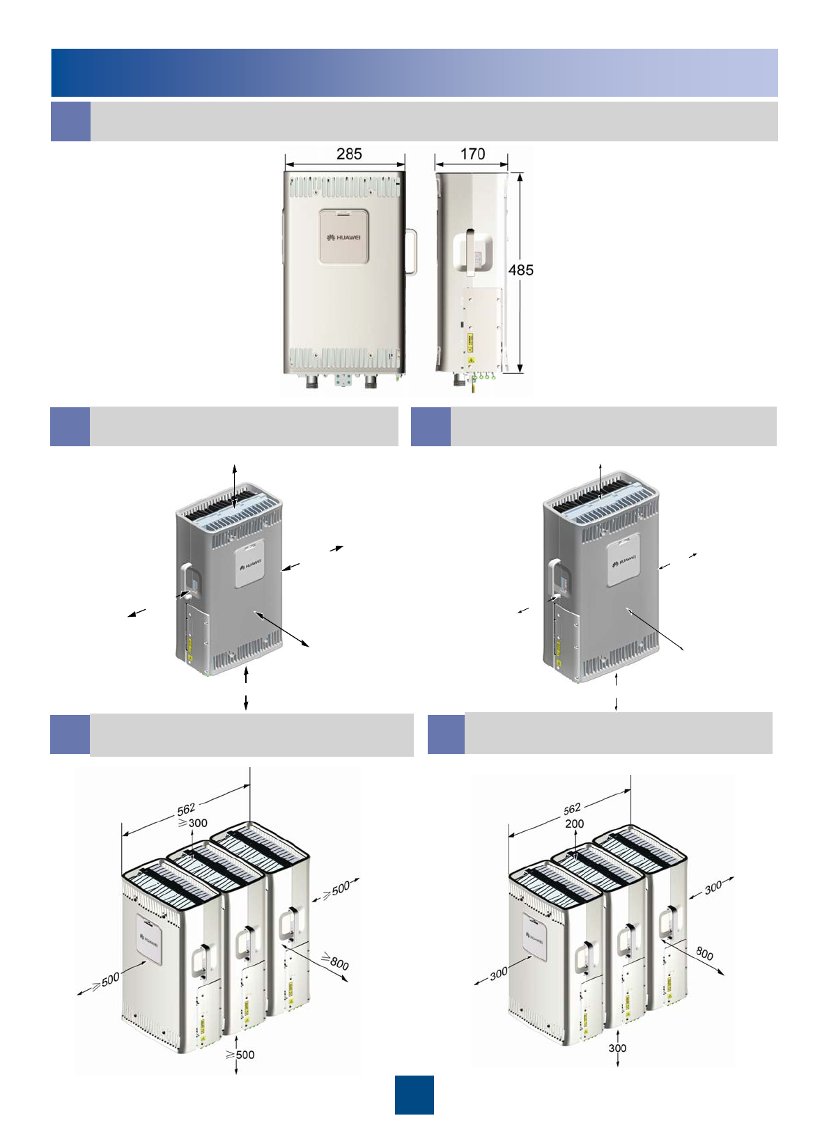
Installation Modes
On a metal pole On a wall On an angle steelOn a U-steel
Metal pole Angle steel U-steel
The following figures show the installations of multiple RRUs on the metal poles.
The RRU can be installed on the tower. For details, see page 24 Lifting the RRU and Installation
Components to the Tower.
60mm~114mm
63mm
~
80mm
63mm ~80mm
30mm
~
50mm
50mm~100mm
63mm~80mm
30mm~50mm
2RRU 4RRU 6RRU
The following figure shows the specifications of the metal pole, angle steel, and U-steel where the RRU is installed.
zA maximum of two RRUs can be installed on a metal pole with a diameter of 60 mm to 76 mm, and the installation mode
must be standard mode. Three or more RRUs must be installed on a metal pole with a diameter of 76 mm to 114 mm in a
centralized way.
zIt is recommended that only one RRU be installed on a U-steel or angle steel.
zWhen installed on a tower, one RRU can be installed only in standard mode or reverse mode rather than side-mounted.
Two RRUs cannot be installed in back-to-back mode.
6
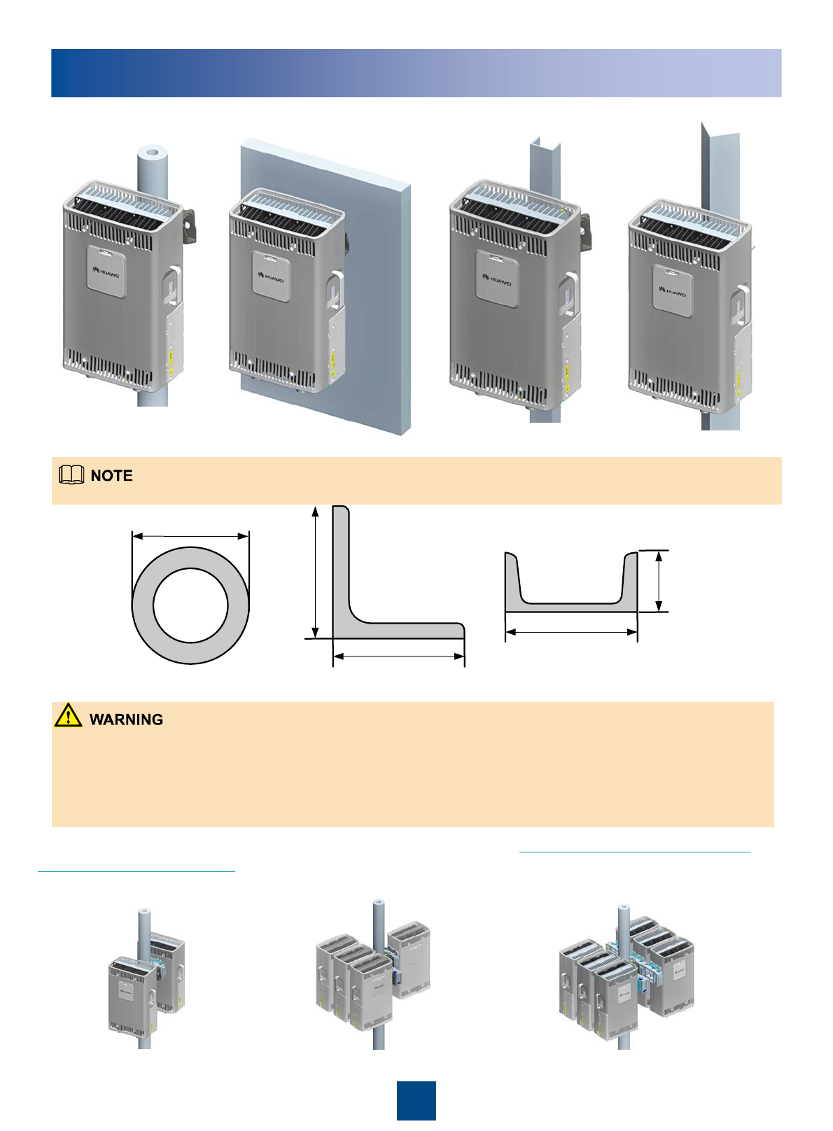
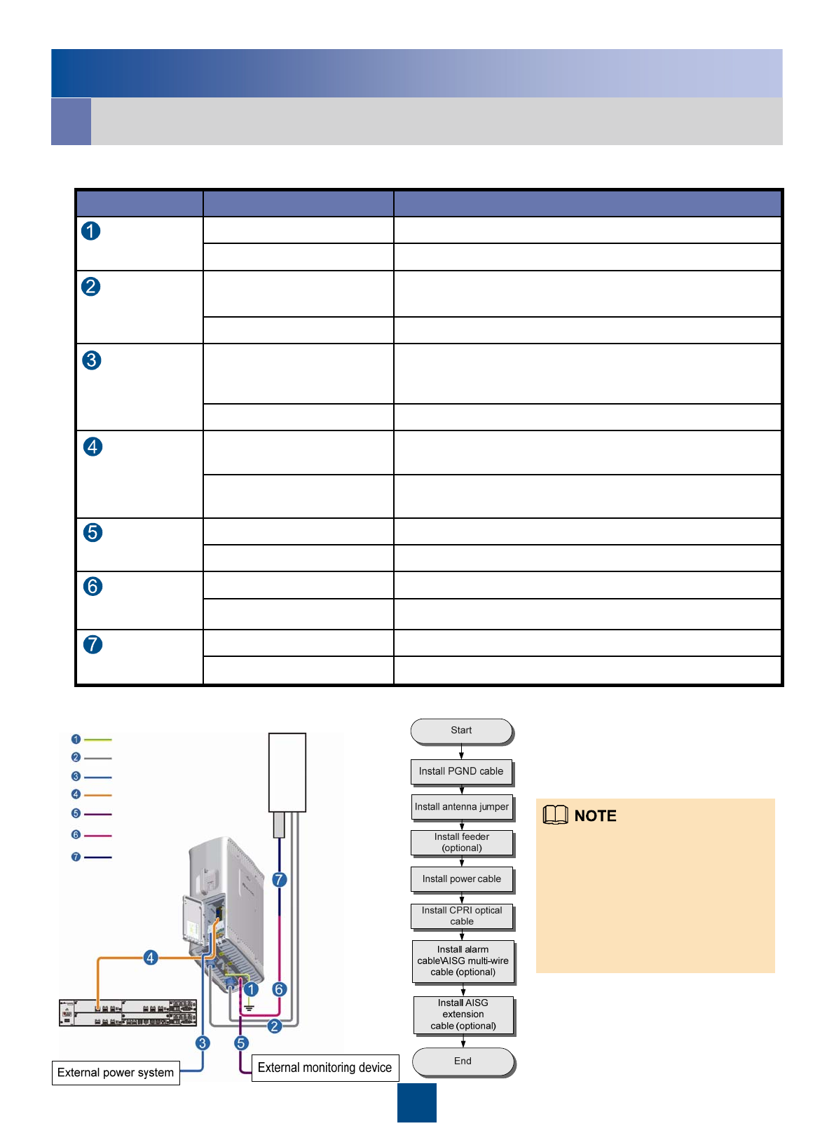
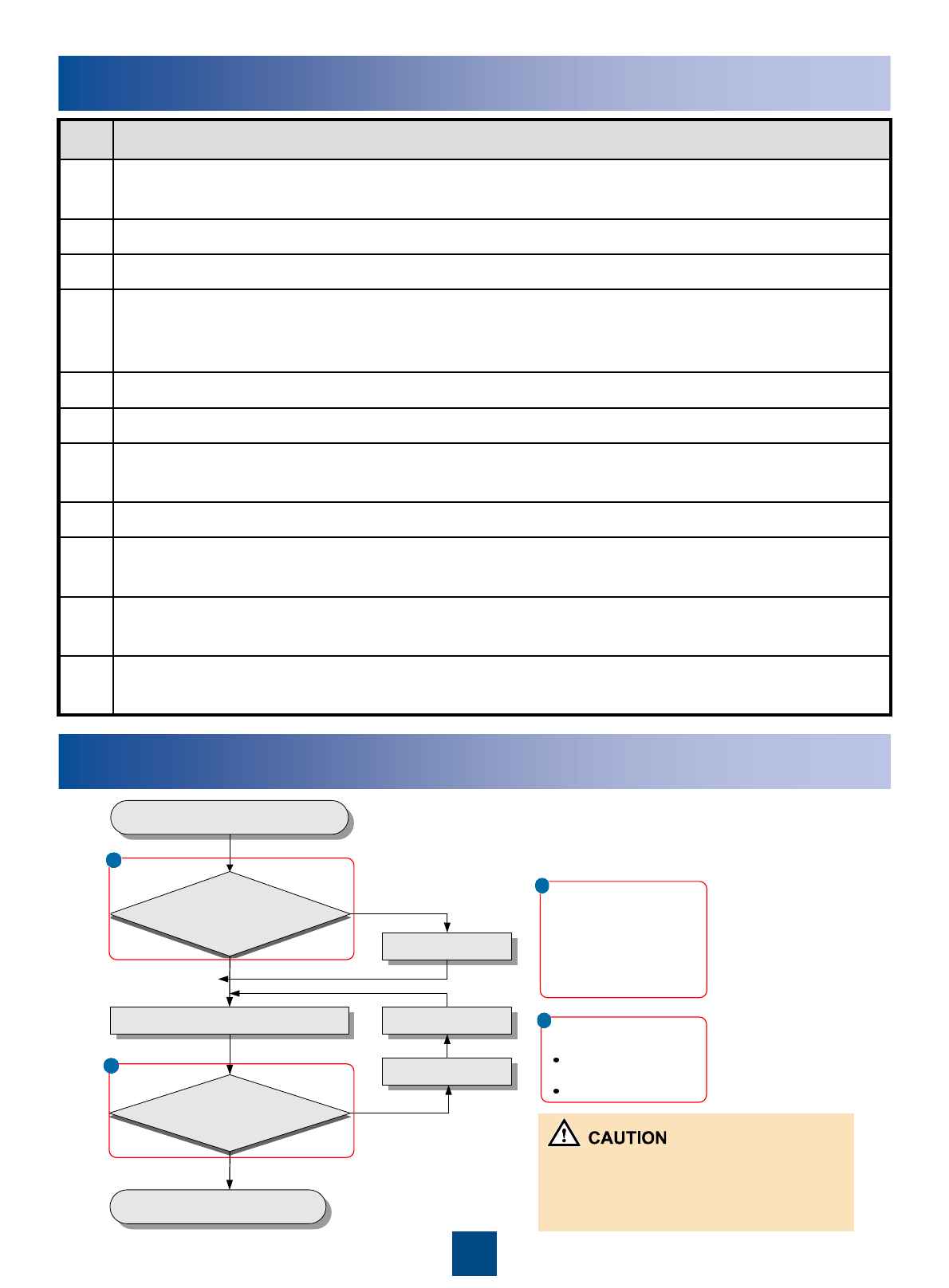
Installation Procedure
Start
End
Install the RRU on a
metal pole
(page 7~11)
Install the RRU on a
wall
(page 12~14)
Install the RRU on a
U-steel
(page15)
Install the RRU on a
angle steel
(page15)
Install the RRU cables
(page16~22)
Power on the RRU
(page 23)
Check the installation
(page 23)
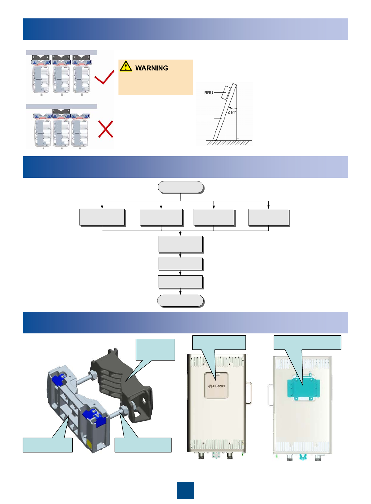
Components Delivered with the RRU
Fixture assembly for installing
the RRU Front of the RRU Back of the RRU
Cover plate Attachment plate
M10x110 BoltMain fixture
Auxiliary
fixture
Installation Modes
The brackets cannot be
combined when the RRUs
are installed on the wall.
When the RRU is installed
on a U-steel or angle steel,
the angle between the U-
steel or angle steel and the
longitudinal direction
cannot exceed 10 degrees.
installation carrier
7
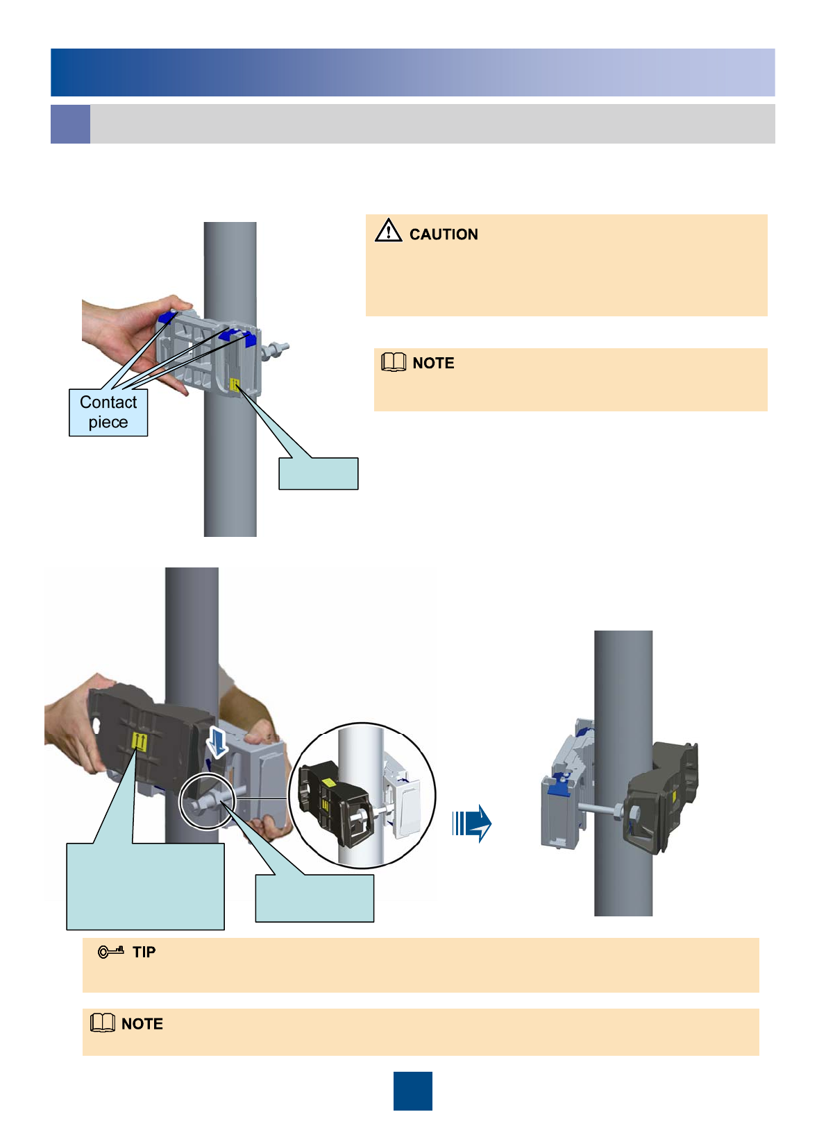
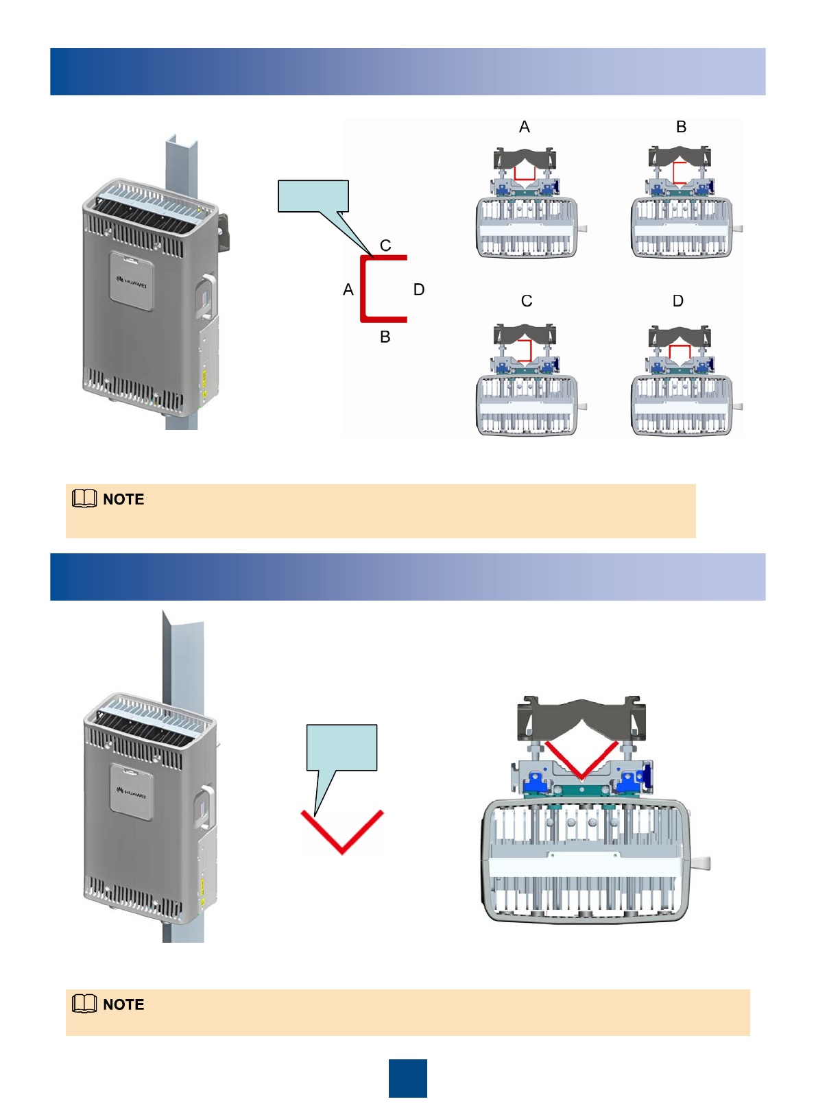
Installing the RRU on a Metal Pole
Installing a Single RRU in Ordinary Mode
a
1. Install the main fixture.
2. Install the auxiliary fixture between the nuts of the dual-nut bolt assembly on the main fixture.
Arrow
Dual-nut bolt
assembly
Ensure that the
arrow on the
auxiliary fixture is
upward.
You can fit the auxiliary fixture on one of the dual-nut bolt assemblies before the installation. Thus, you can simply
install the auxiliary fixture by fitting the other end of it on the other dual-nut bolt assembly.
1. Before installing the main fixture, ensure that the contact piece
on the fixture is fixed.
2. When installing the main fixture, keep the arrow on the main
fixture upward.
It is recommended that the bottom of the main fixture be 1200
mm to 1600 mm above the ground for easy maintenance.
Fit the auxiliary fixture into the dual-nut bolt assemblies.
8
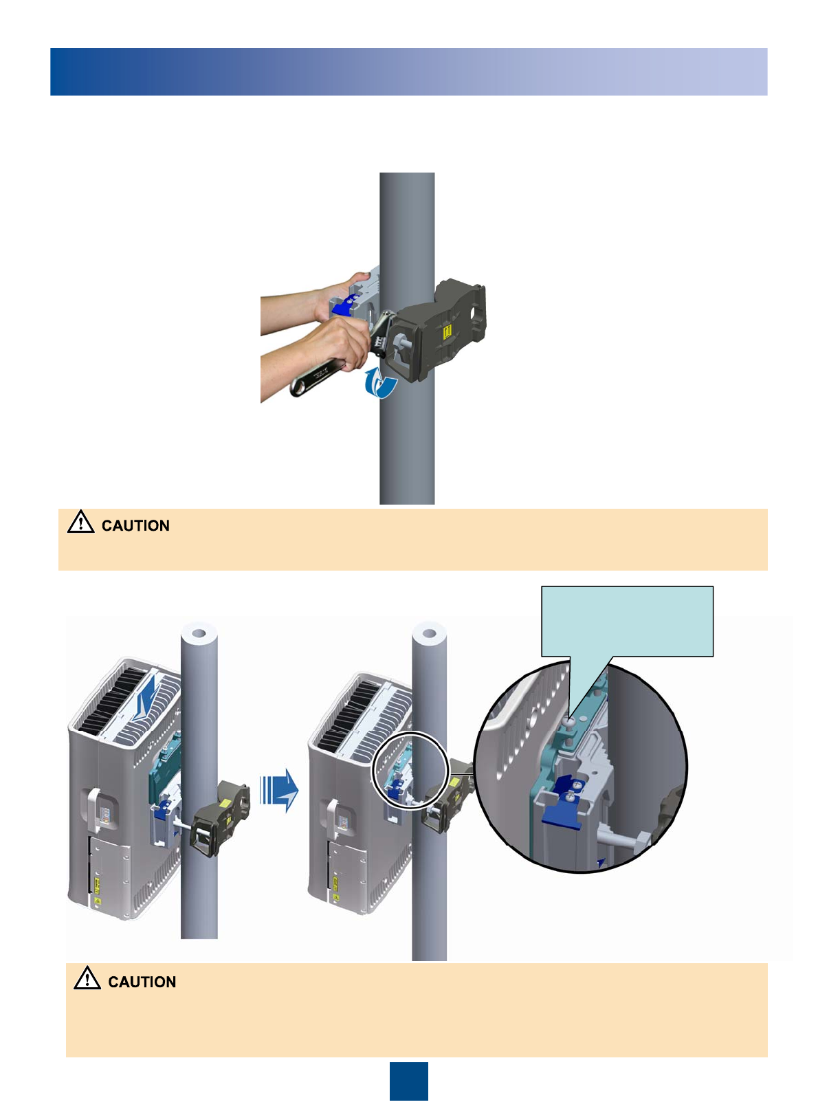
Installing the RRU on a Metal Pole
4. Install the RRU on the main fixture.
When tightening the nuts, ensure that the two dual-nut bolt assemblies are tightened simultaneously. The fastening torque is
40 N• m.
3. Use an adjustable wrench (with the diameter of at least 21 mm) to tighten the dual-nut bolt
assemblies. In this way, the main and auxiliary fixtures are securely mounted on the pole.
1. When you perform this operation, you need to place the foam pads or paper under the RRU to avoid any damage to
the shell.
2. The RF port at the bottom of the RRU does not have load bearing capacity. Do not place the RRU on the ground on
its bottom during the installation.
The screw is a non-
fixed one and is for
removing the RRU.
9
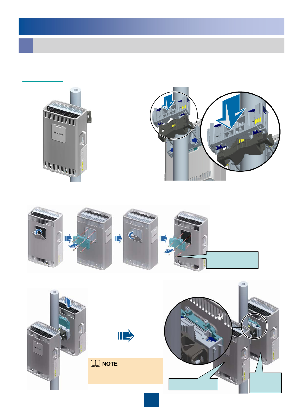
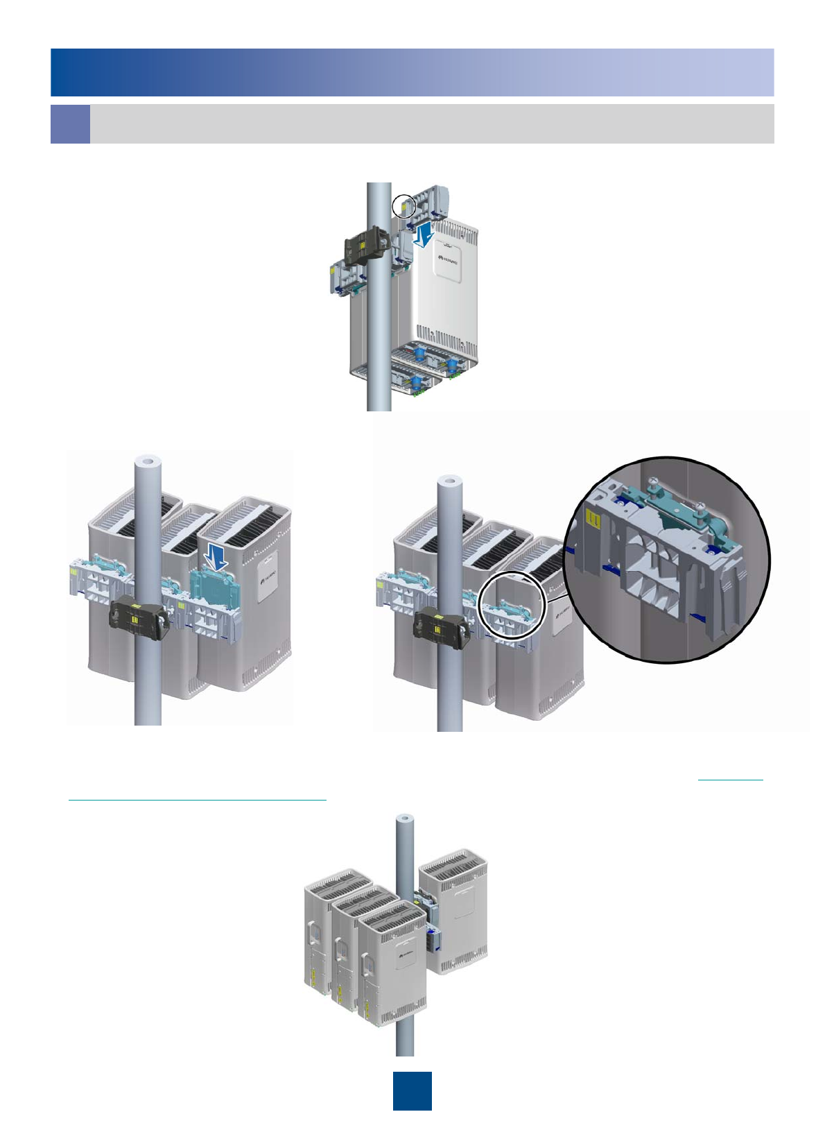
Installing the RRU on a Metal Pole
Installing Two RRUs in Back-To-Back Mode
b
4. Install the second RRU on the main fixture in reverse mode.
2. Install the main fixture of another RRU.
Ensure that the main and auxiliary fixtures
are perfectly fitted.
3. Reinstall the cover plate and attachment plate on the second RRU to interchange their
positions.
1. Install an RRU first. For details, see
page 7 Installing a Single RRU in
Ordinary Mode.
Ensure that the cabling cavities of
the two RRUs face the same
direction when installing the RRUs Ordinary mode Reverse
mode
M6x16
torque: 4.7 N.M
10
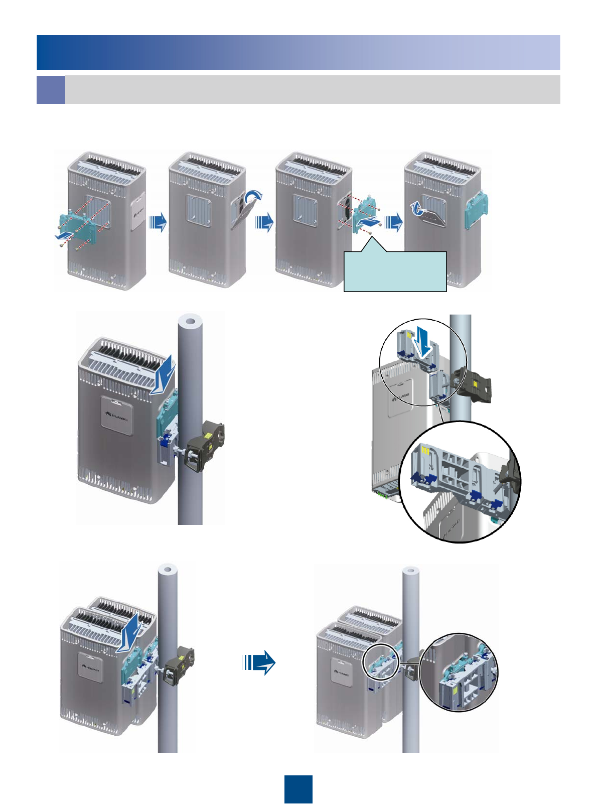
Installing Multiple RRUs in Centralized Mode
c
Installing the RRU on a Metal Pole
4. Install another RRU on the second main fixture.
1. Reinstall the attachment plate on the back and cover plate on one side to interchange their
positions.
2. Install an RRU on a main fixture. 3.Install another main fixture.
M6x16
torque: 4.7 N.M
11
Installing the RRU on a Metal Pole
Installing Multiple RRUs in Centralized Mode
c
5. nstall a third main fixture.
6. Install a third RRU on the third main fixture.
7. Install a fourth RRU on the main fixture. For details, see step 2 to step 4 on page 9 Installing
Two RRUs in Back-To-Back Mode.
12
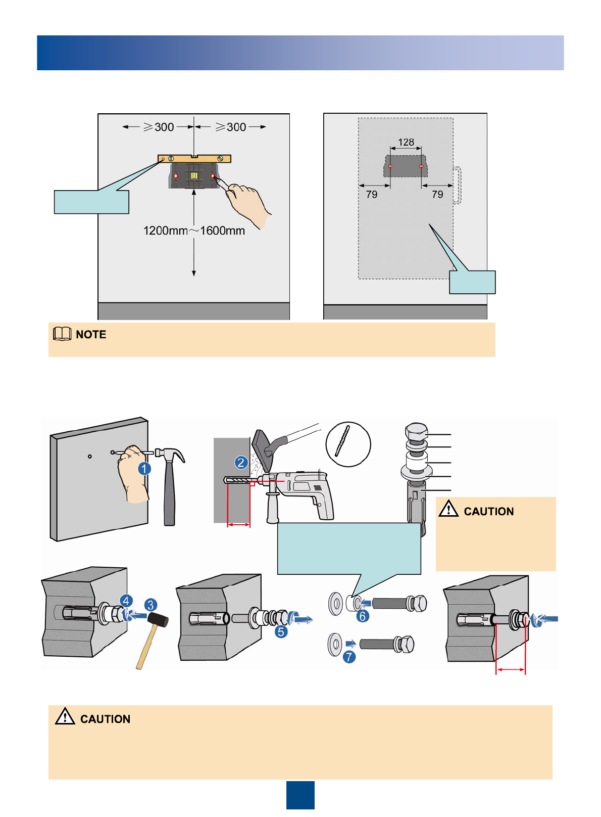
52~60mm
90°
Ø14
20~30mm
Installing the RRU on a Wall
1. Place the auxiliary fixture on the wall at the installation position , use a level bar to measure
the levelness of the fixture, and then mark the anchor points by using a marking pen.
2. Drill holes at the anchor points and then install the expansion bolt assemblies.
It is recommended that the bottom of the auxiliary fixture be 1200 mm to 1600 mm above the ground.
After the expansion bolt
is removed, dispose of
the plastic tube.
Do not hammer the bolt
entirely into the expansion
tube, and leave 20 mm to
30 mm of the bolt outside
the wall.
When RRUs are installed on a wall, the specifications of the wall are as follows:
zFor one RRU, the wall has a weight-bearing capacity of 76 kg.
zThe fastening torque of the expansion bolt reaches 30 N·m, the expansion bolt works properly, and no damages
such as cracks are on the wall.
Level bar
RRU
Bolt M10x65
Flat washer 10
Spring washer 10
Expansion tube
Plastic tube
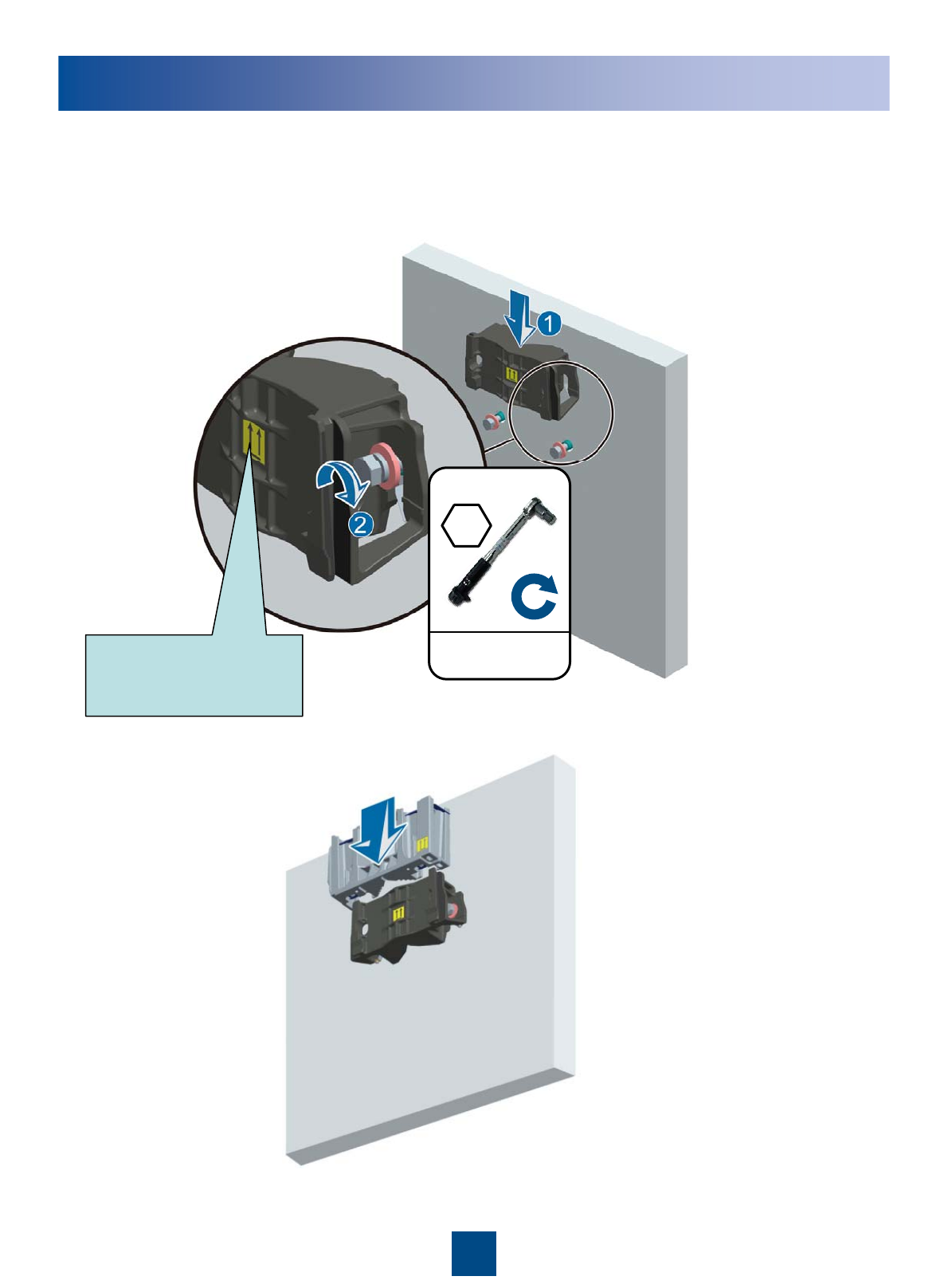
13
Installing the RRU on a Wall
3. Fit the auxiliary fixture on the expansion bolts downward, and then tighten the bolts by using
a combination wrench (with the diameter of at least 17 mm).
4. Install the main fixture.
30N•m
M10X65
Ensure that the arrow
on the auxiliary fixture
is upward.
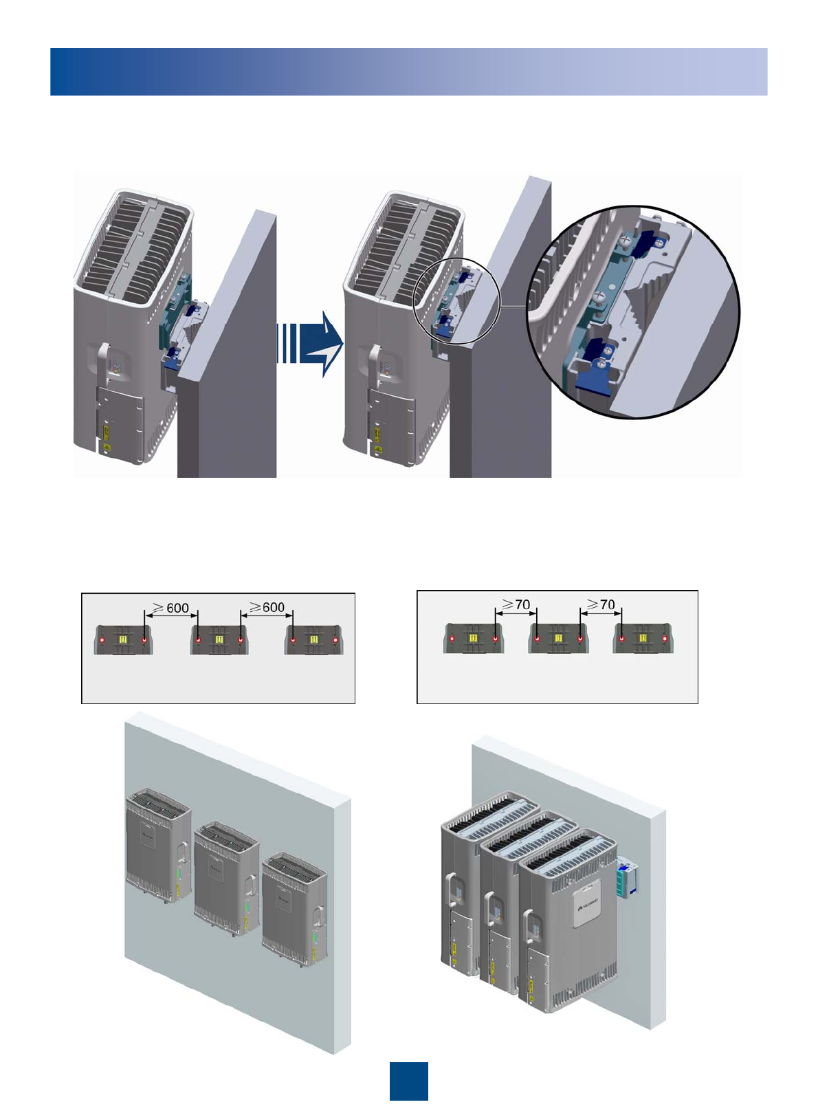
14
Installing the RRU on a Wall
5. Install the RRU.
6. Install Multiple RRUs.
15
Installing the RRU on a U-Steel
The procedure for installing the RRU on a U-steel is the same as that for installing the RRU on a metal pole.
Installing the RRU on an Angle Steel
The procedure for installing the RRU on an angle steel is the same as that for installing the RRU on a metal pole.
U-steel
Angle
steel
Top view
Top view
U-Steel
16
Installing the RRU Cables
RRU Cable Connections
a
The RET/MON port on the RRU is
multi-functional, and can be installed
with either AISG multi-wire cable or
alarm cable. When the length of the
AISG multi-wire cable is not enough,
you can choose the optional AISG
extension cable.
PGND cable
Antenna jumper
Power cable
CPRI optical cable
AISG multi-wire cable
Alarm cable
AISG extension cable
Antenna
BBU
Single RRU
Standard AISG female connector of the AISG multi-wire cableStandard AISG male connector
Standard AISG male connector of the AISG extension cable or RCUStandard AISG female connector
Port labeled RET/MON on the RRUWaterproof DB9 connectorAISG multi-wire
cable
Port labeled RET/MON at the bottom of the RRUDB9 male connectorAlarm cable
External alarm devicesEight cord end terminals
The connectors labeled 2A and 2B are connected to port labeled CPRI0,
CPRI1 or CPRI2 on the LBBP board of the BBU.
DLC connector
CPRI optical
cable
The connectors labeled 1A and 1B are connected to the optical module
on the port labeled CPRI_W on the RRU
DLC connector
AISG extension
cable Standard AISG male connector of the RCUStandard AISG female connector
The blue OT terminal is connected to socket labeled NEG(-)0 in the RRU
cabling cavity. And the black OT terminal is connected to socket labeled
RTN(+)0.
Two OT terminals
(M4)
Power cable
External power supplyBare wire
Feeder or antennaDIN male connector
Ports labeled ANT_TX/RXA and ANT_TX/RXB on the RRU
(Only the ANT_TX/RXA port supports the OOK signal).
DIN male connectorAntenna jumper
Nearest grounding barOT terminal
Grounding bolt on the RRUOT terminal(M6)PGND cable
(16mm2 )
Connector to…Connector TypeCable
Cable List
RCU
17
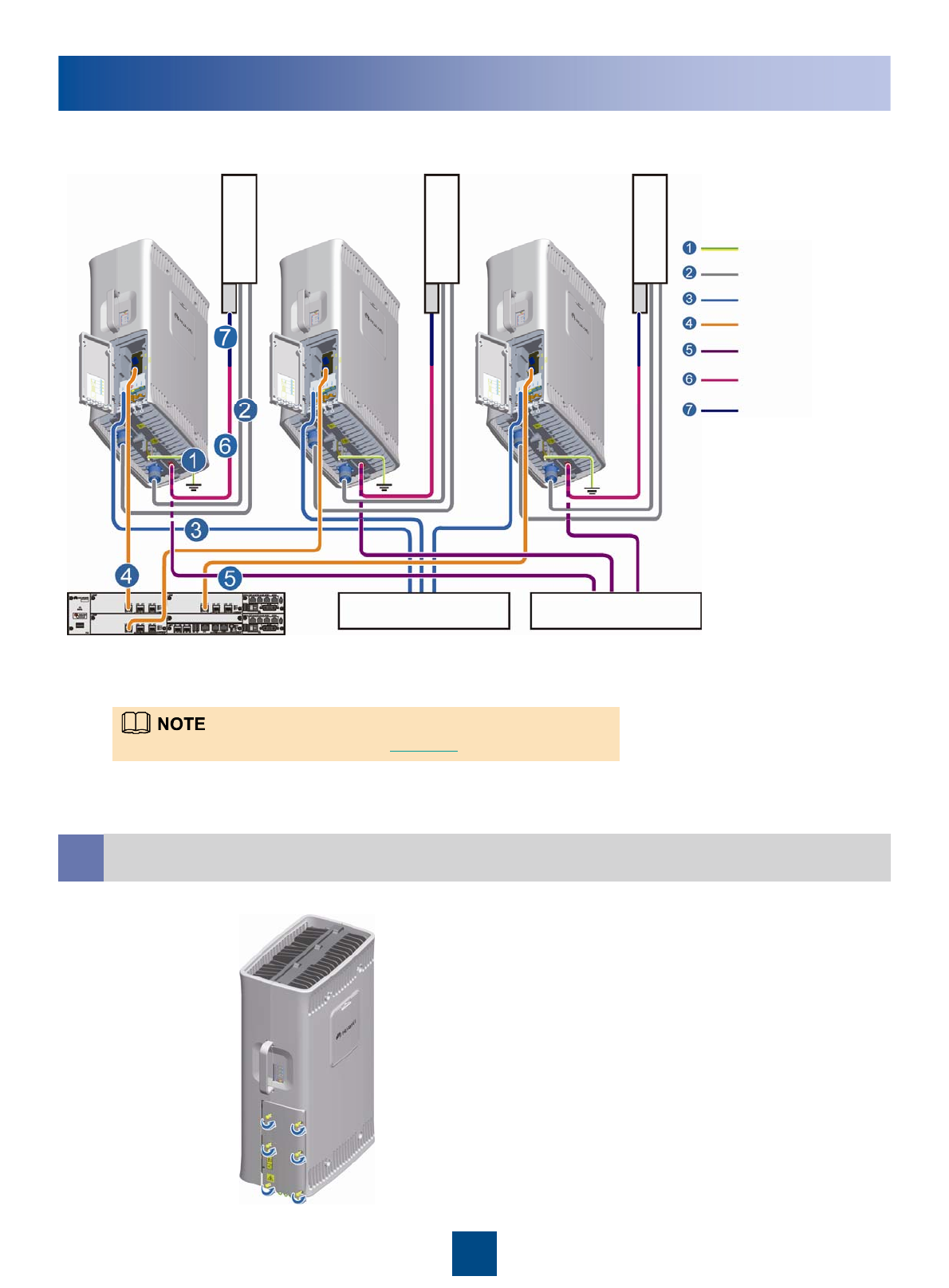
Installing the RRU Cables
For detail information of the cable, see Cable List on Page 17.
External power system External monitoring device
Antenna
Antenna
Antenna
PGND cable
Antenna jumper
Power cable
CPRI optical cable
AISG multi-wire cable
Alarm cable
AISG extension cable
Multiple RRU
RCU
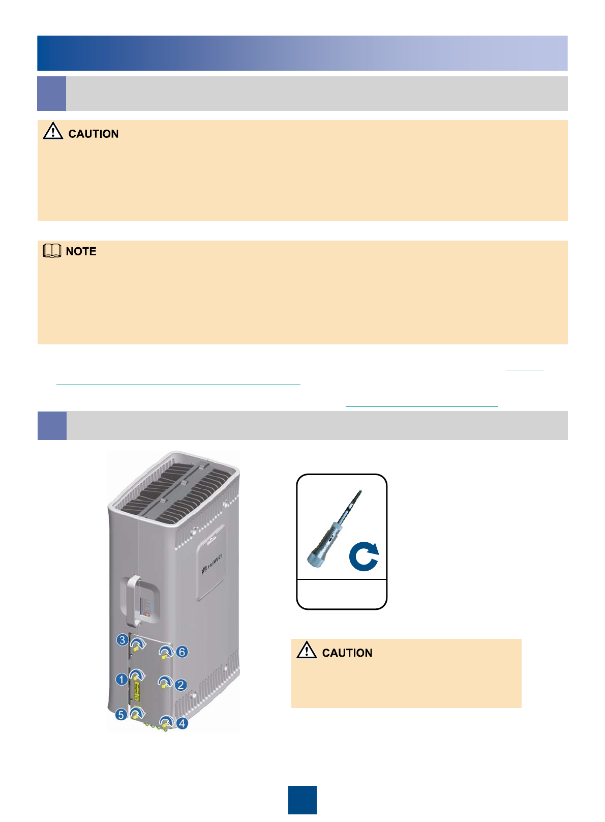
bOpen the cover plate of the RRU cabling cavity
18
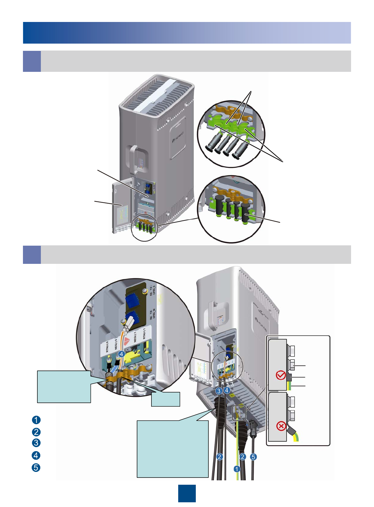
Installing the RRU Cables
CCabling Cavity of the RRU
Waterproof filler
Cover plate of the
cabling cavity
Cabling cavity Cable trough for the
power cable
Cable trough for the optical cable
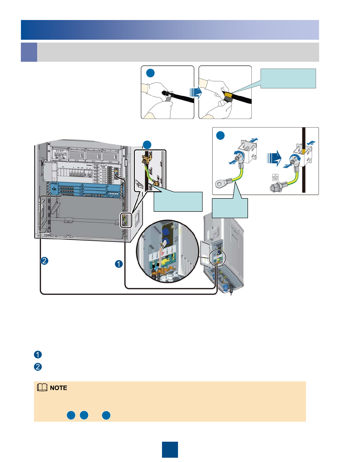
dCable Connections of the RRU
Grounding
screw
OT terminal
PGND cable
First wrap the joint
with the
waterproof tape,
and then wrap the
joint with the PVC
insulating tape.
Strap
Shielding
layer of the
power cable
PGND cable
Antenna jumper
Power cable
CPRI optical cable
AISG multi-wire cable
19
Installing the RRU Cables
fCable Connections of the RRU
For details on how to add the OT terminals to the power cable, see pages 26 to 27 Adding
OT Terminals to the Power Cable of the RRU.
For details installing the Optical Module, see page 28 Installing the Optical Module.
eClose the cover plate of the RRU cabling cavity
1.4N•m
zWhen wrapping the waterproofing tape, apply even force to extend the tape until the width of the tape is 1/2 of the
original width.
zWrap the joint spirally upward, downward, and then upward again. In other words, the joint is wrapped by three layers of
the tape. Ensure that the upper layer of the tape covers about half of the lower layer when wrapping up the tape.
zDo not remove the dustproof cap from the idle antenna port. Perform the waterproof, dustproof, and smokeproof
treatment if necessary. Use the waterproof tape to wrap the joints in outdoor applications.
zUse the power cable clip to press the shielding layer tightly and ensure that the lower part of the shielding layer does not
exceed the position shown in the preceding figure.
zThe grounding resistance of the PGND cable should be less than 10 ohms. The PGND cable cannot be connected to the
grounding terminal.
zGround the shielding layer of the other end of the power cable.
zAfter the cables are installed on the RRU, insert the waterproofing fillers into the idle cable holes.
1. The screw on the cover plate is tightened until the
fastening torque is 1.4 N• m.
2. The screws on the cover plate are tightened in the
order shown in the preceding figure.
20
Installing the RRU Cables
gRRU+APM30H
RRU power cable
CPRI optical cable
1. The RRU power cable is connected to one group of the RRU0 to RRU5 terminals of the PDU.
2. Strip the jacket off the RRU power cable for a small part, press the exposed shielding layer on the strap, and
then connect the PGND cable on the strap to the nearest grounding bolt on the side in the APM30/APM30H, as
shown in , , and .
RRU power
cable
Metal shielding
layer (25mm)
PGND
cable
a
b
c
a
b
c
21
Installing the RRU Cables
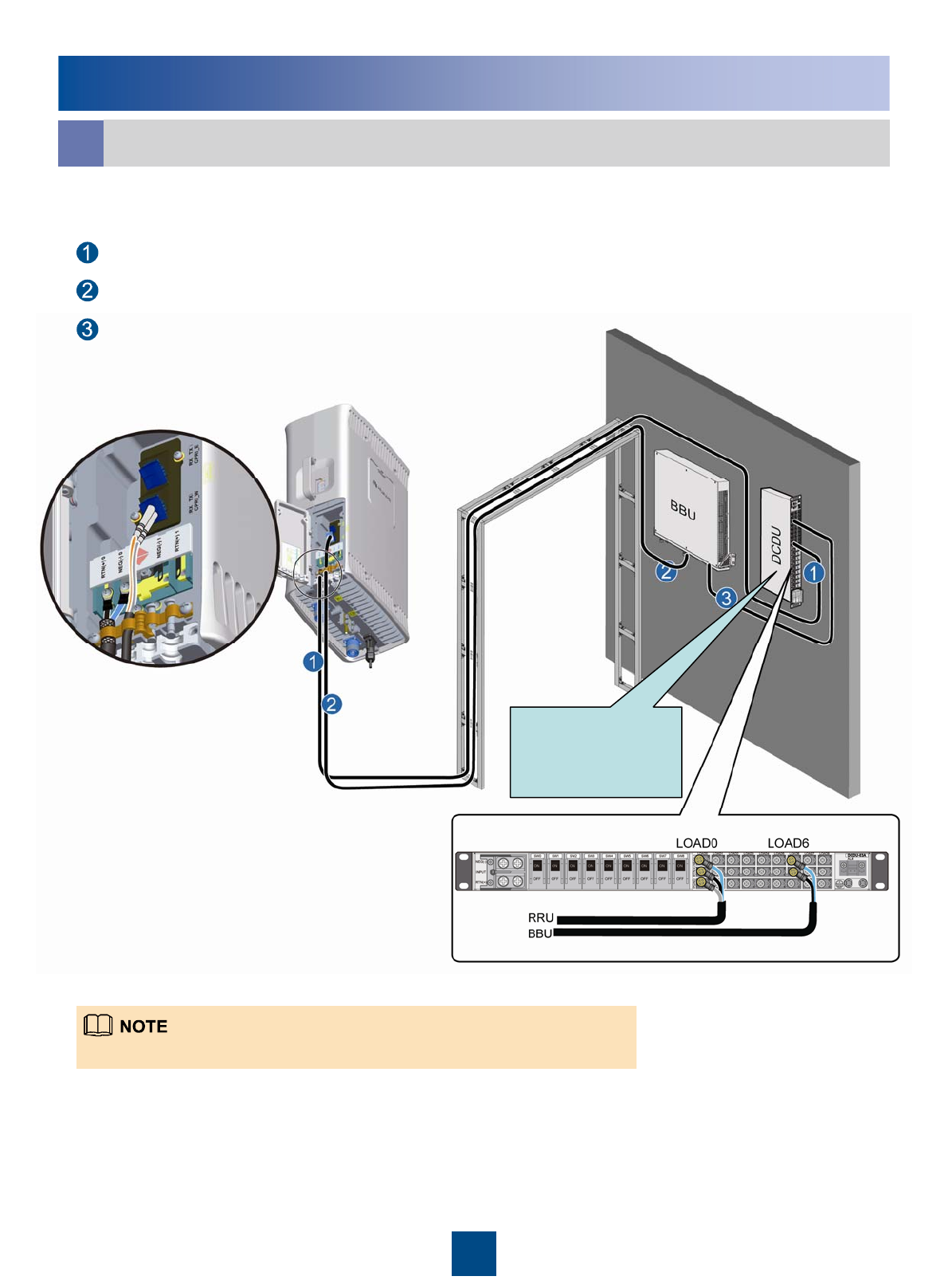
gRRU+BBU on the wall
DCDU panel facing
the side, and the
BBU panel facing
downward
zThe RRU power cable is connected to LOAD0 to LOAD5 on the DCDU-03C.
RRU power cable
CPRI optical cable
BBU power cable
22
Installing the RRU Cables
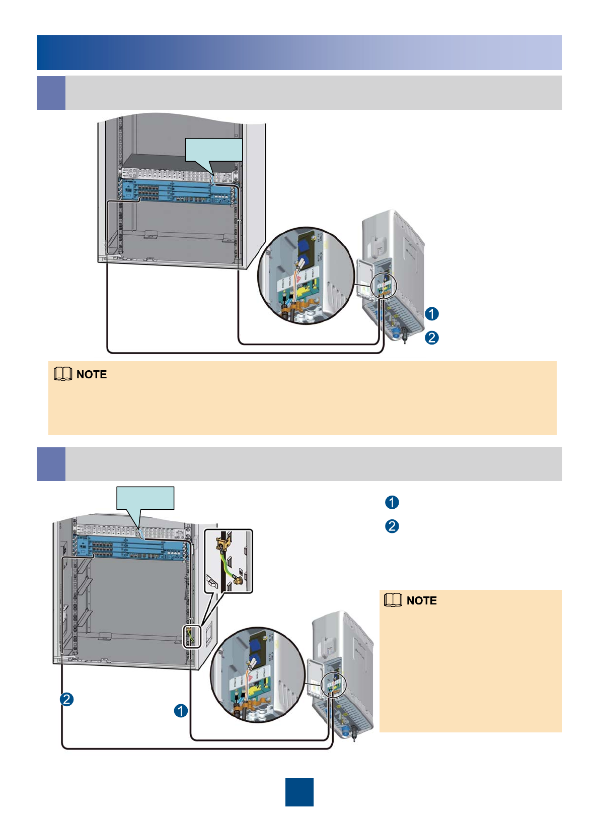
hRRU+19-Inch cabinet
LOAD0
zAt the end of the RRU power cable connected to the DCDU-03C, you need to make the shielding layer of the power
cable into an OT terminal, and then connect the OT terminal to the PGND terminal of the corresponding port on the
DCDU-03C. For details about making an OT terminal, see pages 26 and 27.
zThe RRU power cable is connected to LOAD0 to LOAD5 on the DCDU-03C.
iRRU+TMC/TMC11H
zAt the end of the RRU power cable
connected to the DCDU-03C, you need to
make the shielding layer of the power
cable into an OT terminal, and then
connect the OT terminal to the PGND
terminal of the corresponding port on the
DCDU-03C. For details about making an
OT terminal, see pages 26 and 27.
zThe RRU power cable is connected to
LOAD0 to LOAD5 on the DCDU-03C.
LOAD0
RRU power cable
CPRI optical cable
RRU power cable
CPRI optical cable
23
RRU Hardware Installation Checklist
No joint lies in the middle of the power cable or the PGND cable.5
The connectors of signal cables are intact and securely linked. And the signal cables are not damaged or
broken.
10
All labels, tags, and nameplates are correct, legible, and complete. All the labels at both ends of the cables,
jumpers and feeders should match.
11
The operating grounding and protection grounding of the base station and the lightning protection grounding
of the building share one group of grounding conductors.
9
The power cable, PGND cable and other cables need to be bound separately.8
The power cable and PGND cable are not short-circuited or reversely connected and are not damaged or
broken.
7
The lugs at both ends of the power cable or the PGND cable are securely soldered or crimped.6
Waterproof check: The empty cable troughs in the cabling cavity of the RRU are waterproofed. The cover
plate is tightly buckled on the cabling cavity of the RRU. The RF ports that are not connected with RF
cables are capped and waterproofed. The waterproof caps are fastened.
4
The cover plate is fastened to the RRU cabling cavity.3
The RRU is properly installed.2
The position for each equipment conforms to the engineering design and meets the space requirement.
Sufficient space is reserved for equipment maintenance.
1
ItemsNo.
The RRU should be powered on in 24 hours
after being unpacked. The power off duration
of the RRU cannot exceed 24 hours during
maintenance.
Powering On the RRU
Check whether the
input voltage of the RRU is
normal?
Power on the RRU
Start
End
a
Yes
Power off the RRU
Rectify the fault
b
Check whether the
status of the LEDs on the
RRU is normal?
No
Yes
No
Rectify the fault
aNormal input voltage of the
RRU:
If the BBU is supplied with
-48 V DC power, the
external input power
voltage ranges from -57 V
DC to -36 V DC.
Normal status of the
LEDs on the RRU:
RUN LED: ON for 1s
and OFF for 1s
ALM LED: OFF
b
24
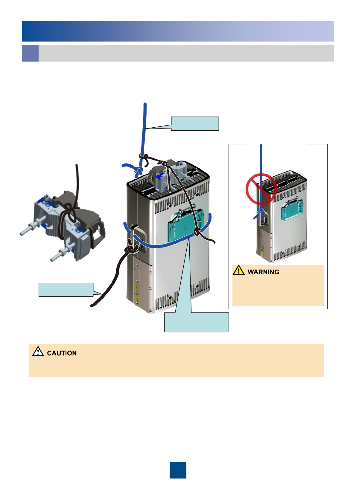
Reference
Lift the RRU and installation components to the tower.
a
【
Steering rope
Lifting rope
zWhen lifting the RRU to the tower, avoid collision of the RRU with the tower.
zLift the RRU to the tower before it is installed on the metal pole, angle steel, or U-steel.
Lower part of the
adapting piece
Do not fix only the handle
of the RRU to the lifting
rope.
1. Lead the lifting rope along the lower part of the adapting piece and then bind the
RRU by using the lifting rope at the handle of the RRU. Bind the main fixture and
auxiliary fixture by using the lifting rope. Bind the handle of the RRU by using the
pulling rope. See the following figure.
25
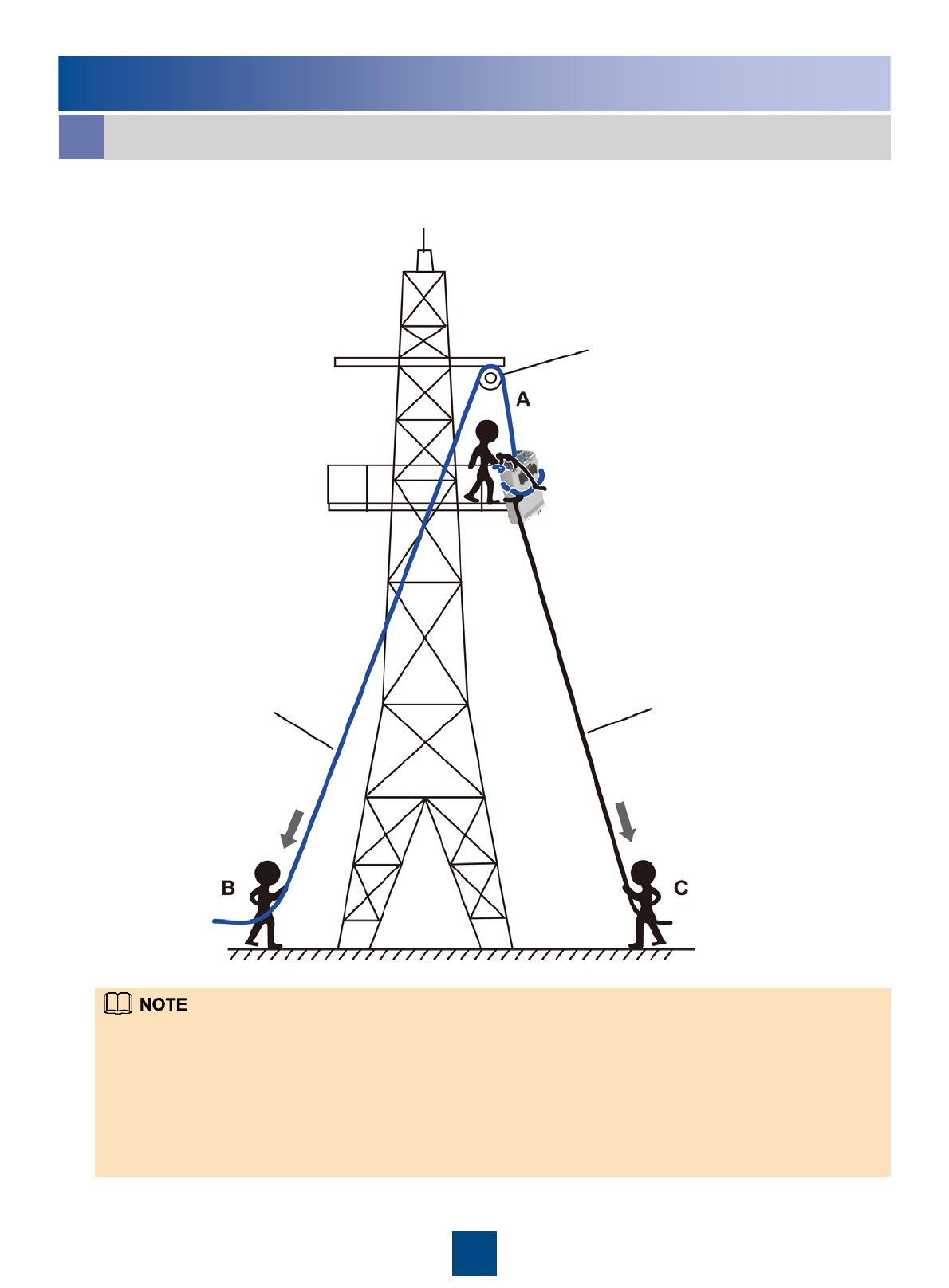
Reference
Lift the RRU and installation components to the tower.
a
2. Lift the RRU and installation components to the tower.
zInstaller A climbs up to the tower, installs the fixed pulley on the support of the tower platform, and then leads the lifting
rope through the fixed pulley.
zInstaller C binds the RRU and installation parts using the lifting rope and fixes the handle of the RRU to the pulling rope.
zInstaller B pulls the lifting rope downwards. At the same time, installer C pulls the steering rope outwards to avoid
collision of the RRU with the installation parts or tower.
zInstallers A catches the RRU and installation parts and then loosen the rope.
zOn a tower, multiple RRUs cannot be installed in centralized mode.
Fixed pulley
Steering rope
Lifting rope
26
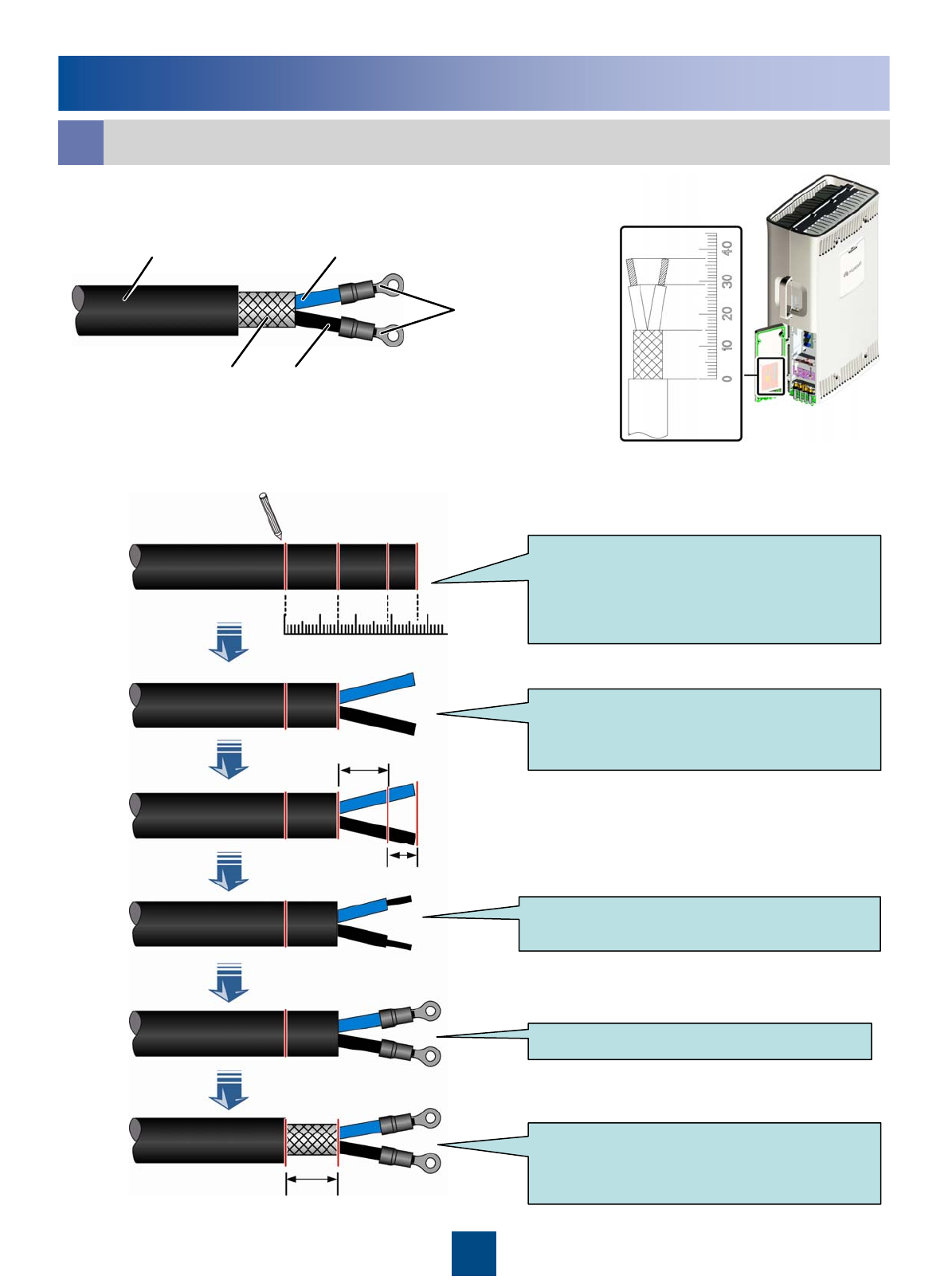
Reference
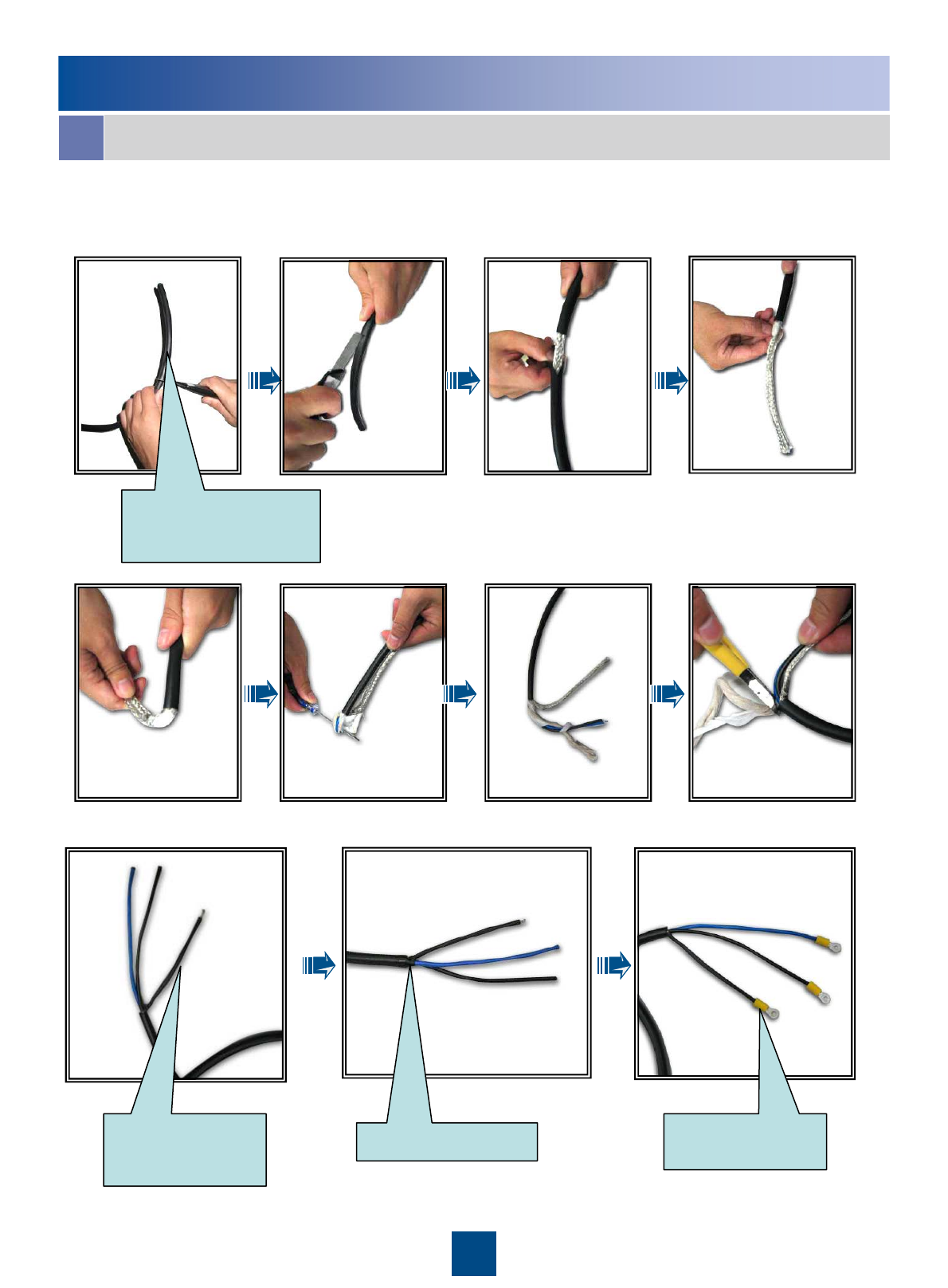
1. OT terminals on the power cable:
To assemble the OT terminals, perform the following steps:
Adding OT Terminals to the Power Cable of the RRU
b
Determine lengths of power cables for
different operations according to the
scales on the inner side of the cover
plate of the cabling cavity.
Based on the determined length,
remove the jacket and shielding layer
off the power cable.
Remove the jacket of a specified length
from each wire.
Add an OT terminal to each wire.
Remove about 15 mm jacket off the
power cable to expose the shielding
layer.
-48 V DC power cable
Shielding
layer GND wire
-48 V power wire
OT terminal
15mm
8mm
14mm
0 10203040
27
Reference
Adding OT Terminals to the Power Cable of the RRU
b
2.Assemble an OT terminal on the power cable at the end connecting to the
power supply device.
Stripped shielding
layer in the heat-
shrinkable tube
PVC insulating tape OT terminal on the
shielding layer
Determine the length on
site. The recommended
length is 150 mm.
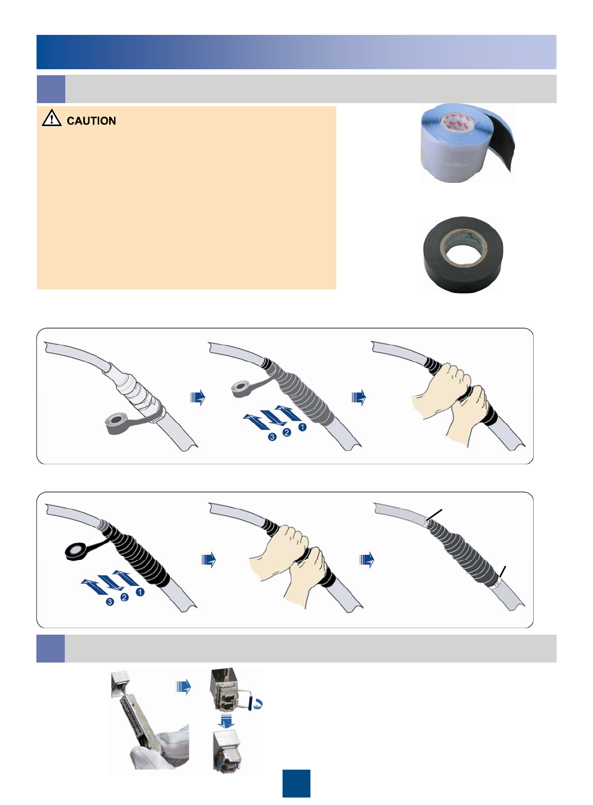
28
1. The waterproof tape should be wrapped for an extra length of 20
mm away from the connectors at both ends.
2. The tapes are wrapped around the connector from the lower part to
the upper part. When wrapped for another layer, the tapes may not be
cut off.
3. Apply average force to pull the tape until the width of the tape is 1/2
of the original width before wrapping up the waterproofing tape.
4. Ensure that the upper layer of the tape covers over 50% of the lower
layer when wrapping up the tape.
5. The Insulation tape should be wrapped for an extra length of 20 mm
away from the edge of the waterproof tape at both ends.
6. Make sure that the last layer of the waterproof tape is wrapped from
lower part to the upper part so that the rain flows along the wrapped
waterproof tape.
Waterproof tape
Insulation tape
1. Wrap up the connectors with three layers of waterproofing tape
2. Wrap up the connectors with three layers of Insulation tape
Tightly pressed
the tape
Tightly pressed
the tape
Use cable ties to fasten
both ends of the tapes.
Cable tie
Cable
tie
Waterproofing the outdoor cables
c
Reference
Installing the optical Module
d
29
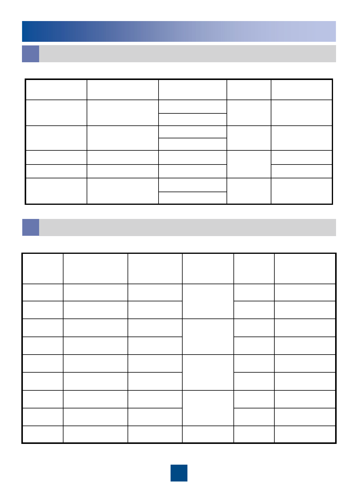
Reference
Pin Assignment of the RRU AISG Extension cable
f
Brown
+24VTwisted pairWhite/brownX2.6X1.6
RS485 AGreenX2.5X1.5
RS485 BTwisted pairWhite/greenX2.3X1.3
Orange
DC Return ATwisted pairWhite/orangeX2.7X1.7
Blue
+12VTwisted pairWhite/blueX2.1X1.1
InstructionWire TypeWire ColorPin of the AISG female
connector
Pin of the AISG
male connector
Pin Assignment for the Wires of the RRU Alarm Cable
g
APM TX+X9
Twisted pair
BrownRS485_RX+X1.3
-
X8
X7
X6
X5
X4
X3
X2
Cord End
Terminal
---X1.shell
APM TX-
Shield
White/brownRS485_RX-X1.5
APM RX+GreenRS485_TX+X1.8
APM RX-Twisted pairWhite/greenRS485_TX-X1.6
GNDOrangeGNDX1.4
SWITCH_INPUT1+Twisted pairWhite/orangeSWITCH_INPUT1+X1.7
GNDBlueGNDX1.4
SWITCH_INPUT0+Twisted pairWhite/blueSWITCH_INPUT0+X1.2
LabelWire TypeWire ColorPin NameDB9
waterproof
Connector

30
Change History
01 (2009-08-10)
This is the draft release.
This describes the changes in the RRU3201 V100R001C01 Installation Guide

HUAWEI TECHNOLOGIES CO., LTD.
Huawei Industrial Base Bantian Longgang
Shenzhen 518129
People’s Republic of China
www.huawei.com