Huawei Technologies RRU3201-AWS Distributed Base Station Remote Radio Unit User Manual Installation Manual
Huawei Technologies Co.,Ltd Distributed Base Station Remote Radio Unit Installation Manual
Installation Manual

HUAWEI TECHNOLOGIES Co., Ltd.
RRU3201 Installation Guide
V100R001
Issue: 01
Part Number: 31504691
Date: 2009-03-15

Safety Information …………………….….…………………… 1
Installation Tools ………………….………….……………….. 2
Space Requirements ………………….……..……………….. 3
Installation Modes …………………………………………...... 4
Installation Procedure ………….…………………………….. 5
Components Delivered with the RRU ……………………… 5
Installing the RRU on a Metal Pole …………………………. 6
Installing the RRU on a Wall ………………………………....11
Installing the RRU on a U-Steel …………….………………..12
Installing the RRU on an Angle Steel ……………………....12
Installing the RRU Cables …………………………………….13
RRU Hardware Installation Checklist ……………………….22
Powering On the RRU ………………...……………………….23
Reference ……………………………….………………………..24
Contents
1Copyright © Huawei Technologies Co., Ltd. 2009. All rights reserved.
Following All Safety Precautions
Before any operation, read the instructions and precautions in this document carefully to minimize the possibility
of accidents.
The Danger, Caution, and Note items in the documents do not cover all the safety precautions that must be
followed. They only provide the generic safety precautions for operations.
When operating Huawei products and equipment, you must comply with safety precautions and special safety
instructions related to corresponding equipment provided by Huawei. The safety precautions in the document
are related to only Huawei products. Huawei is not liable for any consequence that results from the violation of
universal regulations for safety operations and safety codes on design, production, and equipment use.
Complying with the Local Safety Regulations
When operating the device, comply with the local safety regulations. The safety precautions provided in the
documents are supplementary. You must comply with the local safety regulations.
Qualified Personnel Only
The personnel in charge of installation and maintenance must be trained and master the correct operating
methods and safety precautions before beginning work.
Symbols
Safety of Personnel
• The high voltage power supply provides power for running the system. Direct contact with the high voltage
power supply or contact through damp objects may result in fatal danger.
• Non-standard and improper high voltage operations may result in fire and electric shock.
• In a thunderstorm, do not perform operations on high voltage and AC power supply facilities or on a steel
tower and mast.
• Ground the device before powering on the device. Otherwise, the personnel and device are in danger.
• Power off the device before performing operations on the power supply equipment.
• High power radio-frequency signals are harmful to human body. Before installing or maintaining an antenna
on a steel tower or mast with a large number of transmitter antennas, the operator should coordinate with all
parties to ensure that the transmitter antennas are shut down.
• When handling optical fibers, do not stand close to, or look into the optical fiber outlet with unaided eyes.
• Protect yourself when drilling holes. Flying dust may hurt your eyes or you may inhale the dust.
• Power off the batteries before connecting the cables to the batteries. Otherwise, casualties may occur.
• When working at a height, be cautious about falling objects.
Device Safety
• Check the electrical connection of the device before operation and ensure that the device is reliably grounded.
• The static electricity generated by the human body may damage the electrostatic sensitive components on
the circuit board, such as the large-scale integrated circuit (LIC). Wear an ESD wrist strap or ESD gloves when
performing the operation.
• When working on batteries, take measures to prevent short circuits in the batteries and electrolyte spill/loss.
The electrolyte may erode metal and boards, or even cause rust of the equipment or short circuits in the boards.
This symbol indicates that casualty or serious accident may occur if you ignore
the safety instruction.
This symbol indicates that serious or major injury may occur if you ignore the
safety instruction.
Safety Information
This symbol indicates that the operation may be easier if you pay attention to the
safety instruction.

Installation Tools
2
Wire cutter ESD glovesPower cable crimping pliers
Cross screwdriver(M3~M6) Straight screwdriver(M3~M6)
Adjustable wrench
(with the diameter of at least 32mm)
Torque screwdriver
Long measuring tape
Vacuum cleaner
Cable peeler
Marking pen
(with the diameter of no more than 10mm)
Multimeter
ESD gloves
Combination wrench
(21mm~21mm)for pole installation
(17mm~17mm) for wall installation
Wire cutter
Heat gun
Percussion drill(Ø14)
Knife
Claw hammer
Power cable crimping pliers
Level bar
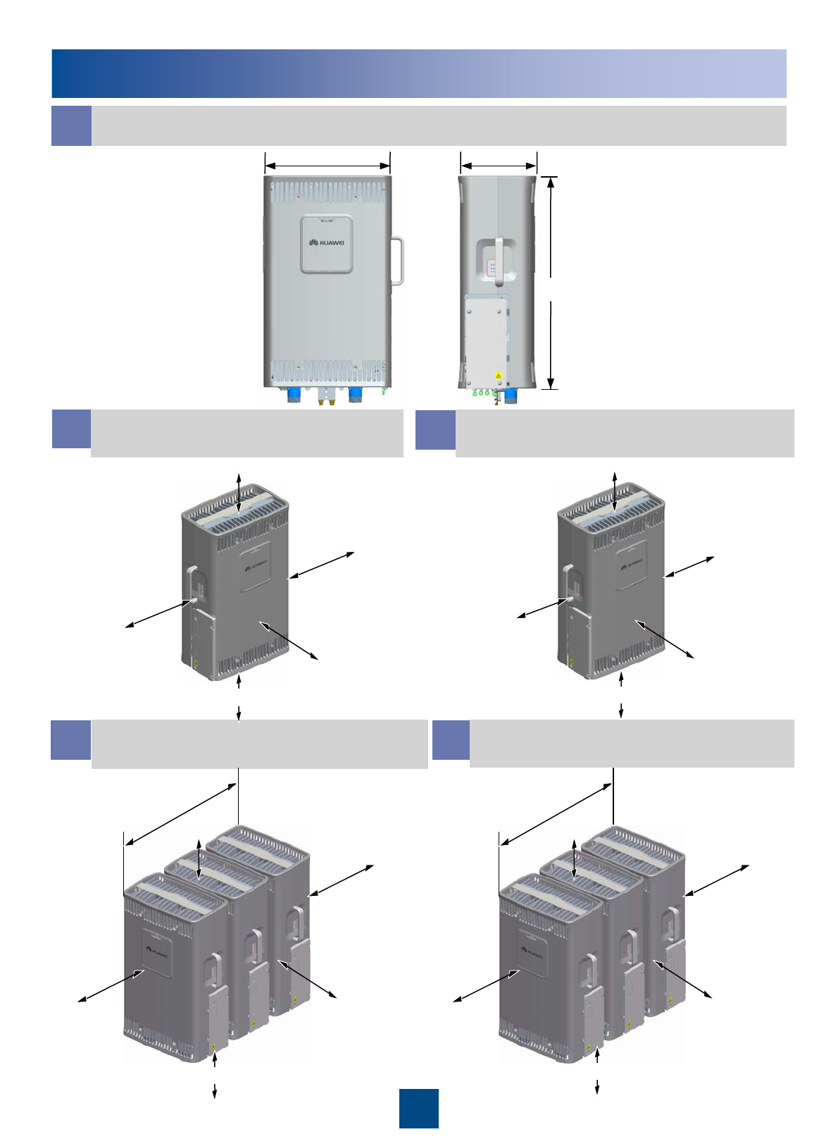
Space Requirements (Unit: mm)
a
bc
d
RRU Dimensions
Recommended Clearance
for a Single RRU Minimum Clearance for a
Single RRU
Recommended Clearance for
Multiple Centralized RRUs eMinimum Clearance for
Multiple Centralized RRUs
3
285
485
170
≥300
≥800
≥300
≥600
≥500
100
600
200
400
300
≥500
≥500
≥300
562
≥800
≥500
300
300
200
562
800
300
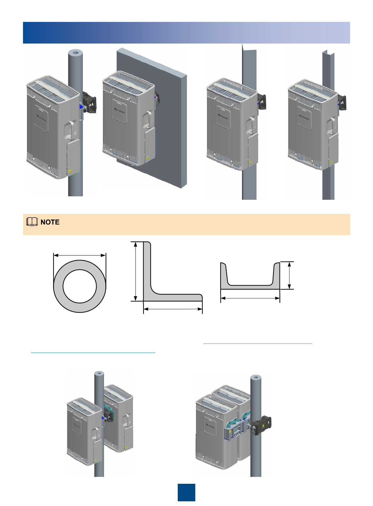
Installation Modes
On a metal pole On a wall On a U-steelOn an angle steel
The following figure shows the specifications of the metal pole, angle steel, and U-steel where the RRU is installed.
Metal pole Angle steel U-steel
The following figures show the installations of multiple RRUs on the metal poles.
The RRU can be installed on the tower. For details, see page 24 Lifting the RRU and
Installation Components to the Tower
4
60mm
~
114mm
63mm
~
80mm
63mm
~
80mm
30mm
~
50mm
50mm
~
100mm
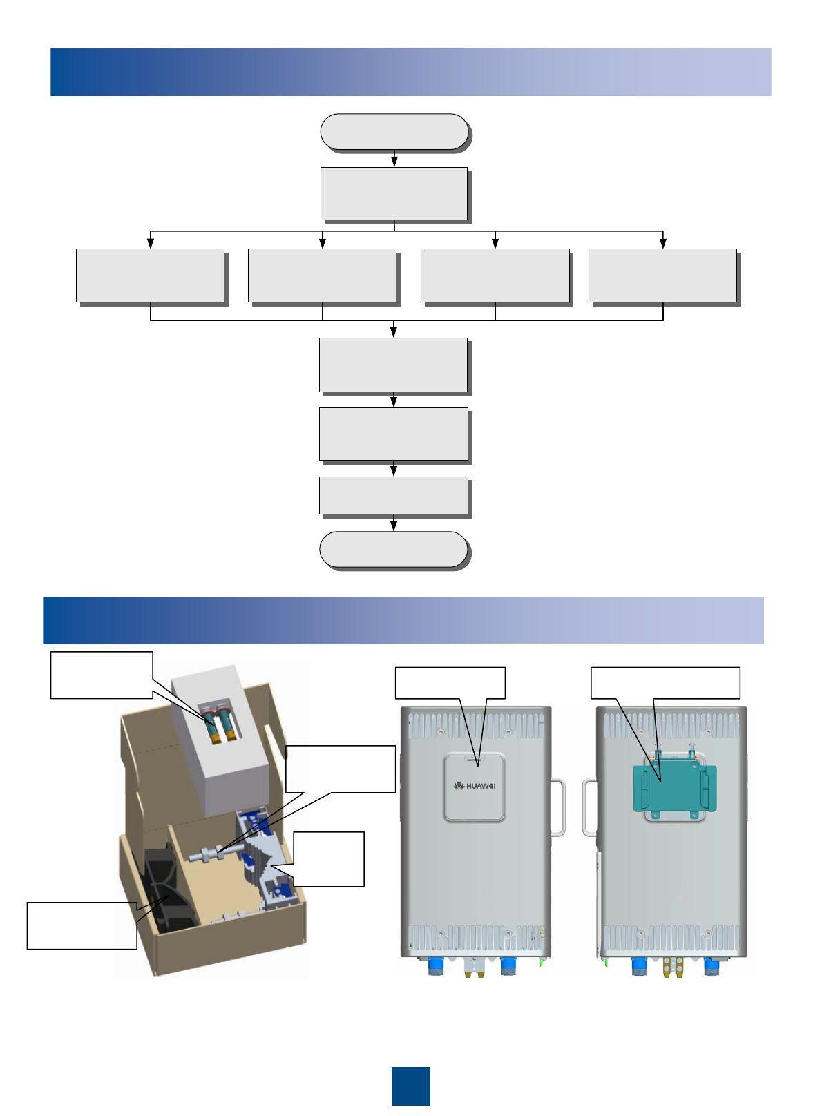
Installation Procedure
Components Delivered with the RRU
Fixture assembly for
installing the RRU
Front of the RRU Back of the RRU
Cover plate Attachment plate
M10x110
Bolt
Main
fixture
Auxiliary
fixture
expansion
bolt
5
Start
Prepare the
installation
(slide5)
End
Install the RRU on a
metal pole
(slide6~10)
Install the RRU on a
wall
(slide11)
Install the RRU on
an angle steel
(slide12)
Install the RRU on a
U-steel
(slide12)
Install the cables of
the RRU
(slide13~21)
Power on the RRU
(slide23)
Check the
installation
(slide22)
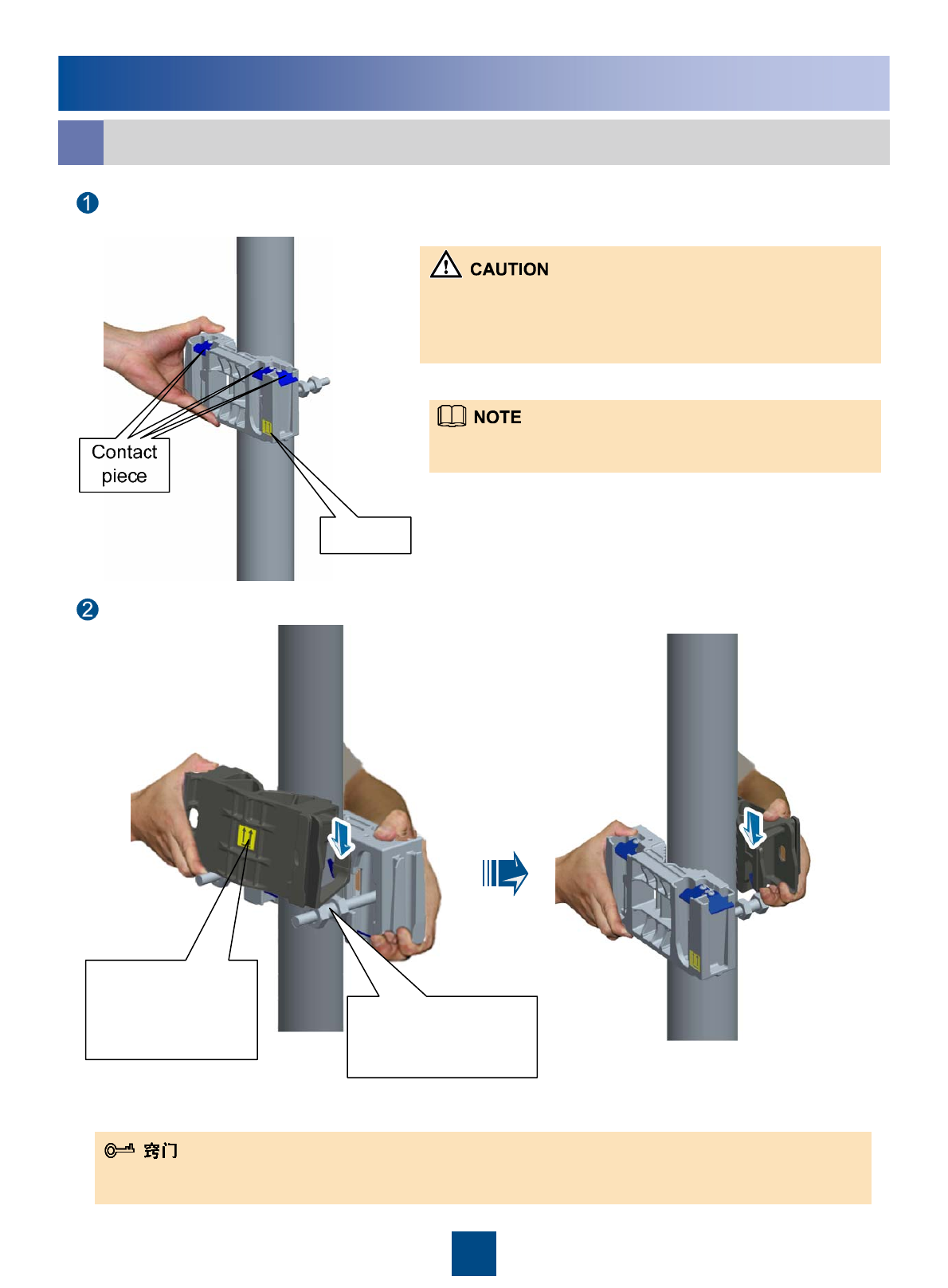
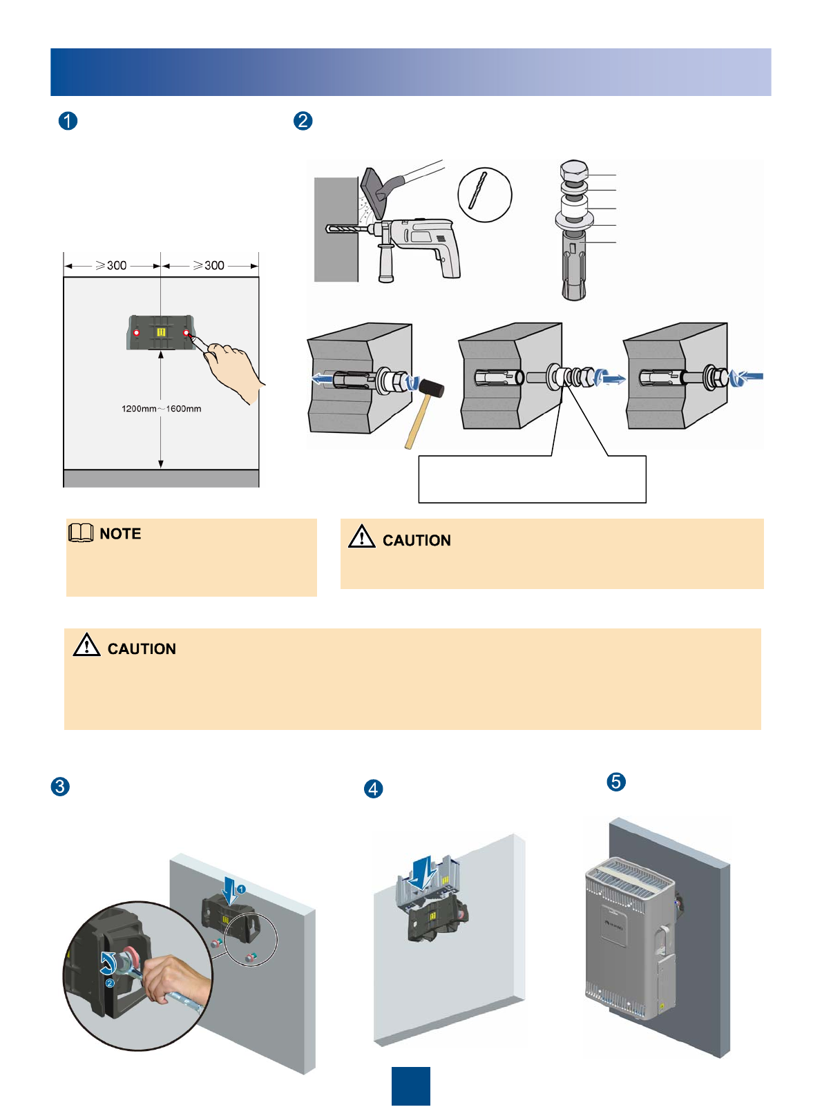
Installing the RRU on a Metal Pole
Installing a Single RRU in Ordinary Mode
a
Install the main fixture.
Install the auxiliary fixture between the nuts of the dual-nut bolt assembly on the main fixture.
1. Before installing the main fixture, ensure that the contact piece
on the fixture is fixed.
2. When installing the main fixture, keep the arrow on the main
fixture upward.
Arrow
It is recommended that the bottom of the main fixture be 1200
mm to 1600 mm above the ground for easy maintenance.
6
Ensure that the
arrow on the
auxiliary fixture is
upward.
Installation position
for the auxiliary
fixture.
You may fit one end of the auxiliary fixture on one dual-nut bolt assembly before installation. And then fit the other end
on the other dual-nut bolt assembly during the installation.
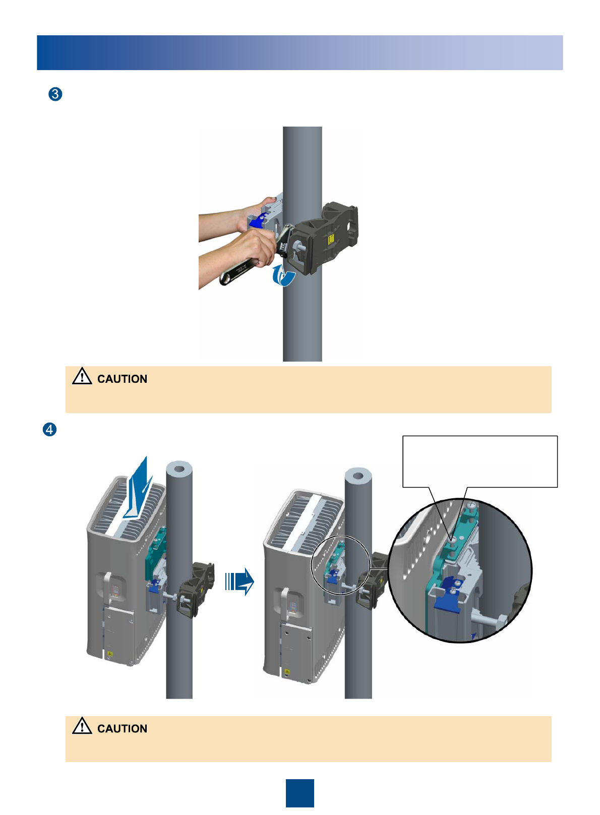
Installing the RRU on a Metal Pole
Use an adjustable wrench (21 mm) to tighten the nut. In this way, the main and auxiliary
fixtures are securely mounted on the pole.
Install the RRU on the main fixture.
The screw is a non-fixed
one and is for removing
the RRU.
The RF port at the bottom of the RRU does not have load bearing capacity.
Do not place the RRU on the ground on its bottom during the installation.
When tightening the nuts, ensure that the two dual-nut bolt assemblies are tightened simultaneously. The fastening
torque is 35 N• m to 40 N• m.
7
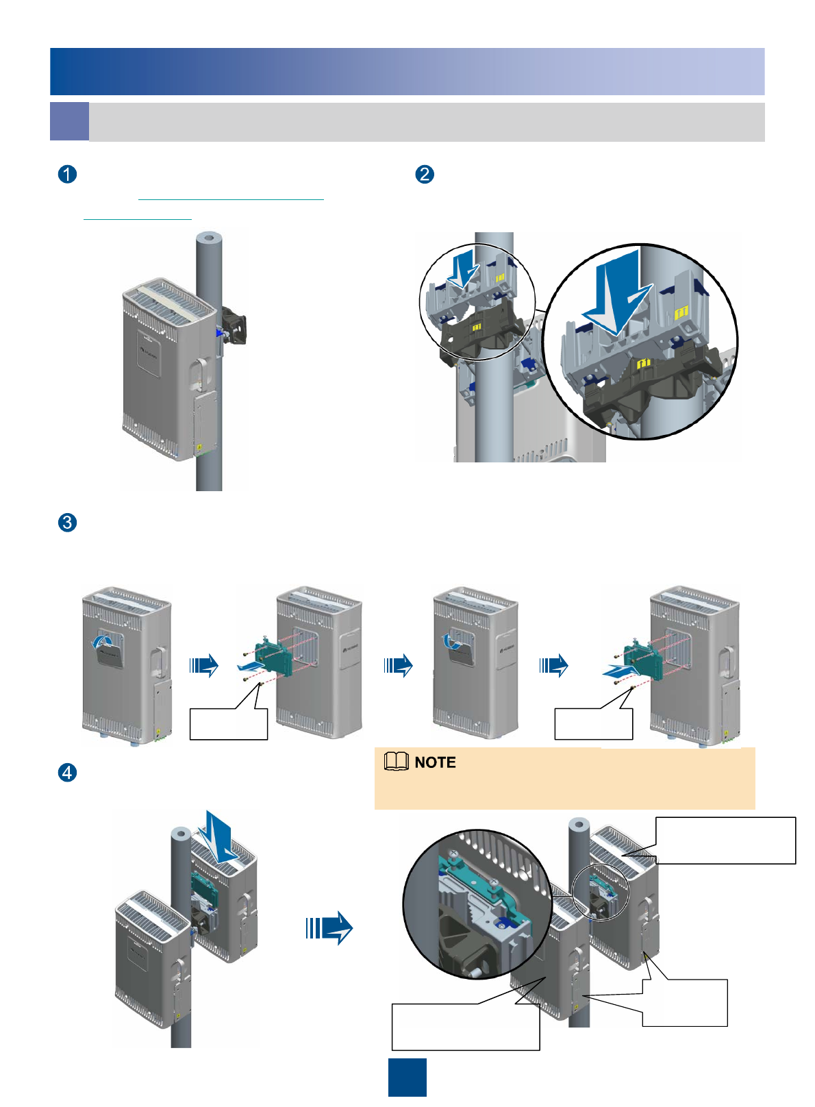
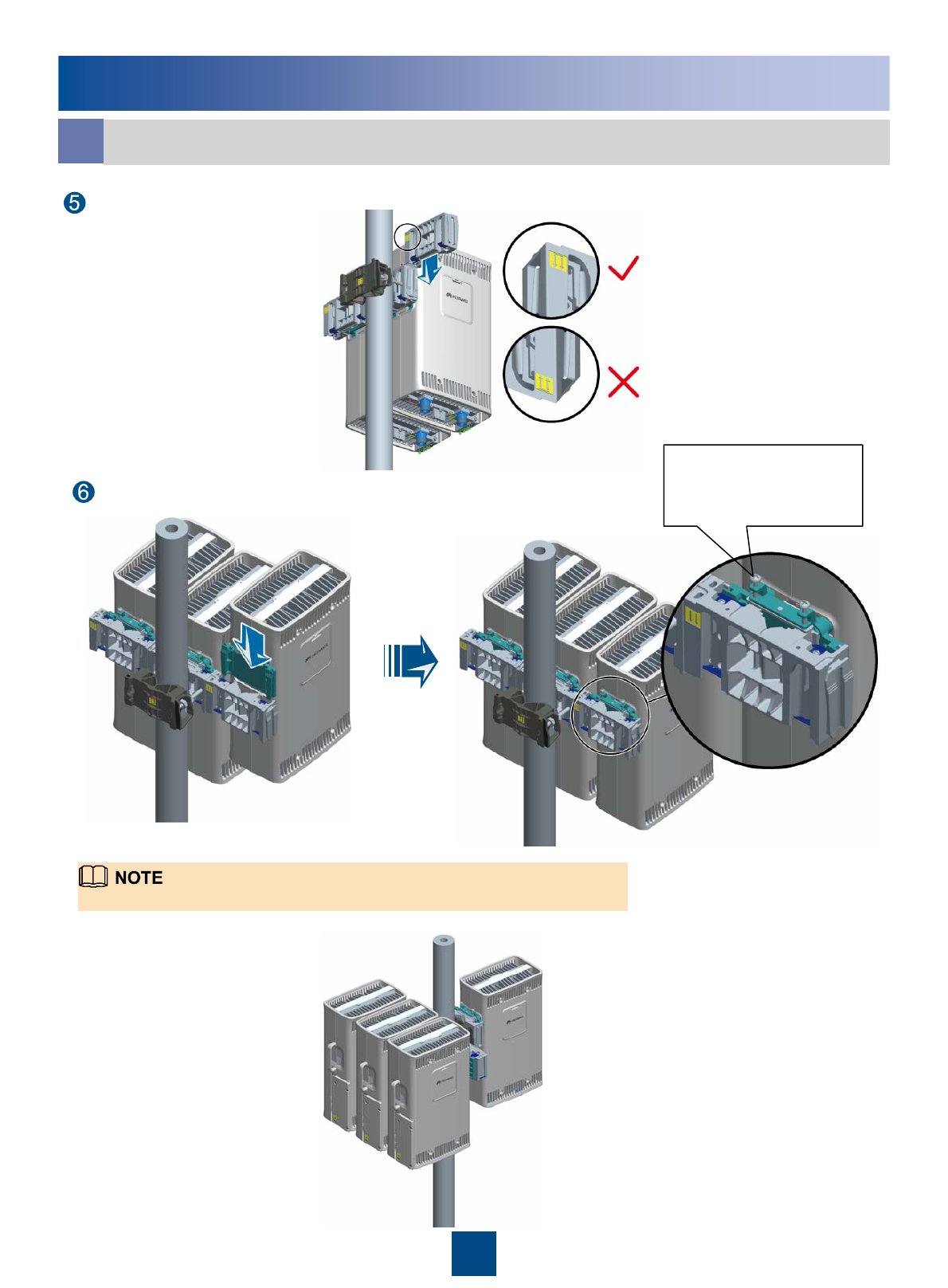
Installing the RRU on a Metal Pole
Installing Two RRUs in Back-To-Back Mode
b
Install the second RRU on the
main fixture.
Install the main fixture of another RRU.
Ensure that the main and auxiliary fixtures
are perfectly fitted.
Reinstall the cover plate and attachment plate on
the second RRU to interchange their positions.
Install an RRU first. For details, see
page 6 Installing a Single RRU in
Ordinary Mode.
RRU installed in
ordinary mode
RRU installed in
reverse mode
Cabling
cavity
Ensure that the cabling cavities of the two RRUs face the same
direction when installing the RRUs.
M6x16
8
M6x16
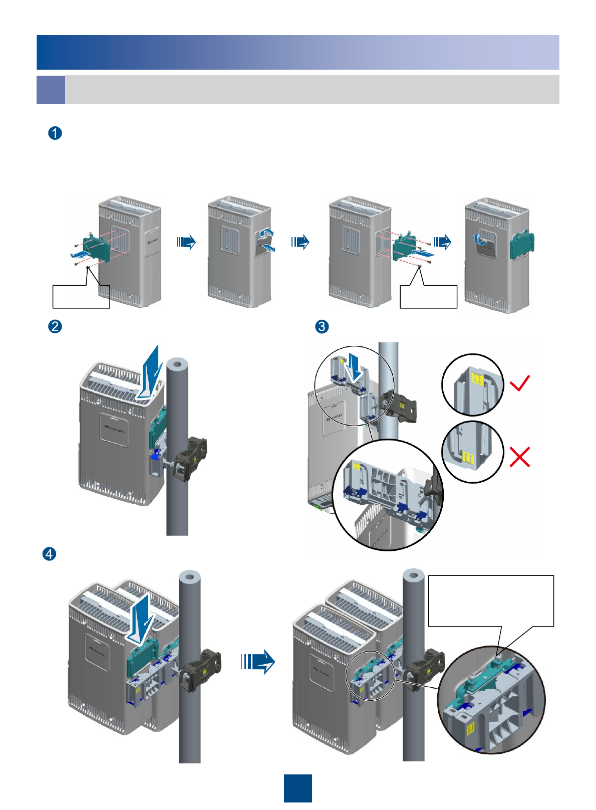
Installing Multiple RRUs in Centralized Mode
c
Installing the RRU on a Metal Pole
Install another RRU on the second main fixture.
Reinstall the attachment plate on the back and cover
plate on one side to interchange their positions.
Install an RRU on a main
fixture. Install another main fixture.
M6x16
9
M6x16
The screw is a non-
fixed one and is for
removing the RRU.
Installing the RRU on a Metal Pole
Installing Multiple RRUs in Centralized Mode
c
Install a third main fixture.
Install a third RRU on the third main fixture.
The following figures show the installation positions for a fourth RRU.
10
The screw is a non-
fixed one and is for
removing the RRU.
Installing the RRU on a Wall
Place the auxiliary fixture
on the wall at the
installation position and
then mark the anchor
points by using a marking
pen.
Drill holes at the anchor points and then install the
expansion bolt assemblies.
Fit the auxiliary fixture on the
expansion bolts downward, and
then tighten the bolts by using a
combination wrench (17 mm).
Install the main
fixture.
Install the RRU.
It is recommended that the bottom of the
auxiliary fixture be 1200 mm to 1600 mm
above the ground.
Do not hammer the bolt entirely into the expansion tube, and leave 20
mm to 30 mm of the bolt outside the wall.
11
When RRUs are installed on a wall, the specifications of the wall are as follows:
1. When a single RRU is installed on the wall at the back, the wall must have the load capacity of 1.25 kN bolt stress;
2. When a single RRU is installed on the wall at the side, the wall must have the load capacity of 2.0 kN bolt stress.
3. When three RRUs are installed on the wall at the side, the wall must have the load capacity of 6.0 kN bolt stress.
After the expansion bolt is removed,
dispose of the plastic tube.
M10x65 bolt
Spring washer 10
Plastic tube
Flat washer 10
Expansion tube
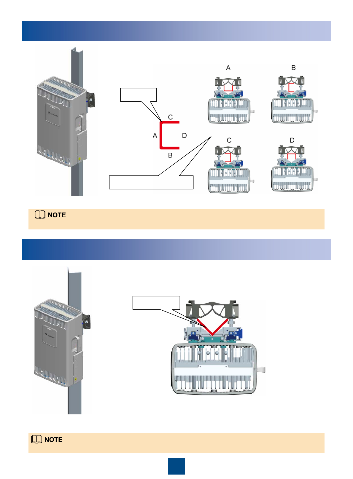
Installing the RRU on a U-Steel
The procedure for installing the RRU on a U-steel is the same as that for installing the RRU on a metal pole.
Installing the RRU on an Angle Steel
The procedure for installing the RRU on an angle steel is the same as that for installing the RRU on a metal pole.
U-steel
Four installation modes
Angle steel
12
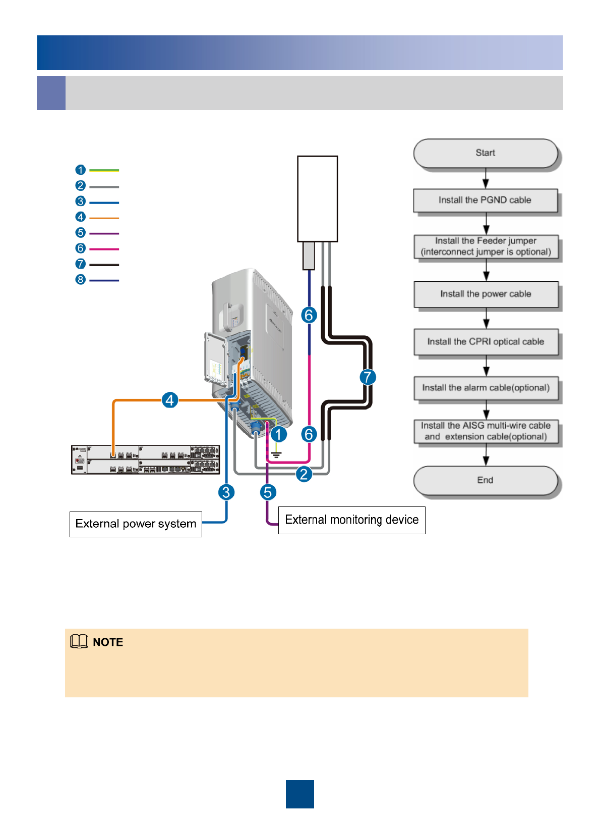
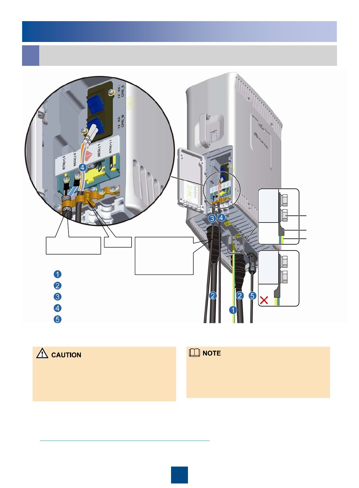
Installing the RRU Cables
Cable Connections of a Single RRU
a
The RET/MON port on the RRU is multi-functional, and can be installed with either AISG multi-wire cable or
alarm cable. When the length of the AISG multi-wire cable is not enough, you can choose the optional AISG
extension cable.
13
PGND cable
Feeder jumper
Feeder
Power cable
CPRI optical cable
AISG multi-wire cable
Alarm cable
AISG extension cable
Antenna
BBU
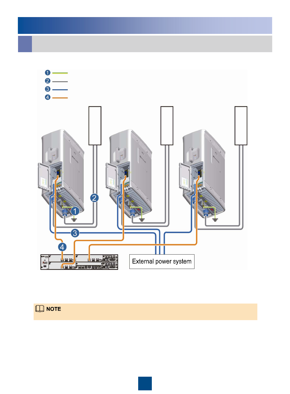
Installing the RRU Cables
Cable Connections of Multiple RRUs
b
14
For detail information of the cable, see Cable List on Page 15 and 16.
PGND cable
Feeder jumper
Power cable
CPRI optical cable
BBU
Antenna
Antenna
Antenna
Installing the RRU Cables
The connectors labeled 1A and 1B are
connected to port labeled CPRI_W on
the RRU
DLC connectorCPRI optical cable
The connectors labeled 2A and 2B are
connected to port labeled CPRI0,
CPRI1 or CPRI2 on the LBBP board of
the BBU.
DLC connector
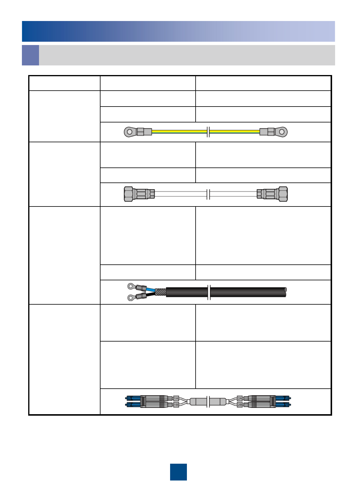
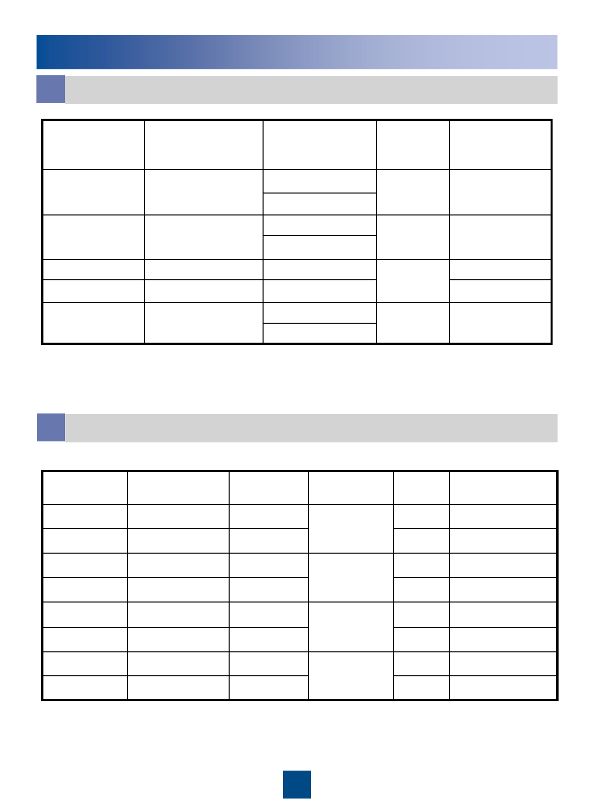
The blue OT terminal is connected to
socket labeled NEG(-)0 in the RRU
cabling cavity. And the black OT
terminal is connected to socket labeled
RTN(+)0.
Two OT terminalsPower cable
External power supplyBare wire
Feeder or antennaDIN male connector
Ports labeled ANT_TX/RXA and
ANT_RXB on the RRU
DIN male connectorAntenna jumper
Nearest grounding barOT terminal
Grounding bolt on the RRUOT terminalPGND cable
Connected to…Connector TypeCable
Cable List
c
15
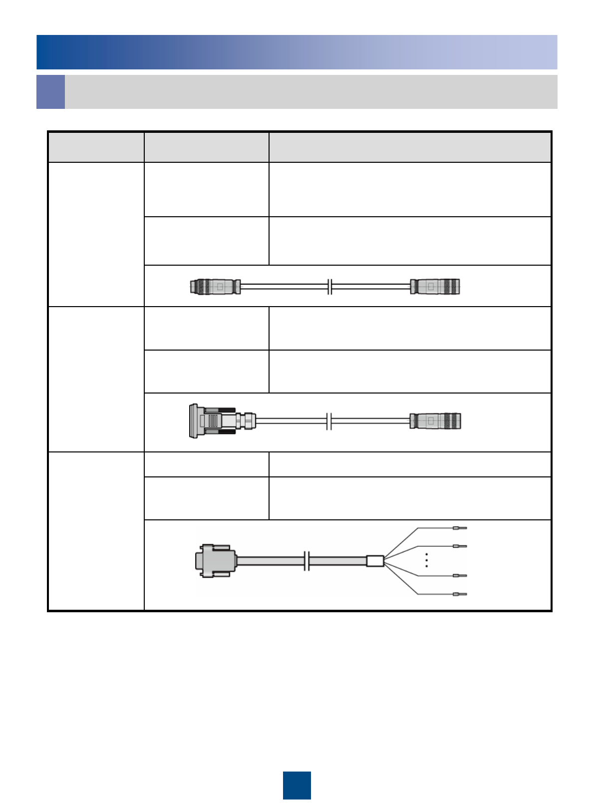
Installing the RRU Cables
Port labeled RET/MON on the RRUWaterproof DB9
connector
AISG multi-
wire cable
Standard AISG male connector of the AISG
extension cable or RCU
Standard AISG
female connector
External alarm devicesEight cord end
terminals
Port labeled RET/MON at the bottom of the RRUDB9 male connectorAlarm cable
Standard AISG male connector of the RCUStandard AISG
female connector
Standard AISG female connector of the AISG
multi-wire cable
Standard AISG male
connector
AISG
extension
cable
Connected to…Connector TypeCable
cCable List
16
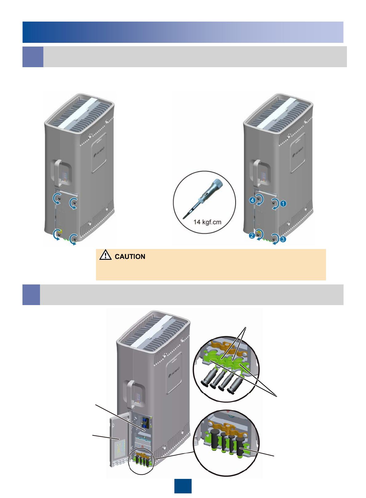
Installing the RRU Cables
dOpening and Closing the Cover Plate of the RRU Cabling Cavity
•Open the cover plate of the RRU
cabling cavity •Close the cover plated of the RRU cabling
cavity
1. The screw on the cover plate is tightened until the fastening torque is 14 N.m.
2. The screws on the cover plate are tightened in the order shown in the preceding figure.
eCabling Cavity of the RRU
17
Waterproof filler
Cover plate of
The cabling
cavity
Cabling
cavity Cable trough for the
Power cable
Cable trough for
the optical cable
安装RRU线缆
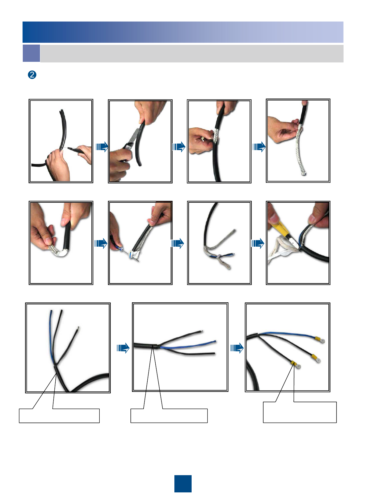
fCable Connections of the RRU
For details on how to add the OT terminals to the power cable, see pages 26 to 27
Adding OT Terminals to the Power Cable of the RRU.
The tape is wrapped spirally upwards, downwards,
and then upwards again in three layers. For every two
adjacent tape layers, the tape on the upper layer
overlaps about half the width of the tape on the lower
layer.
1. Press the strap on the exposed shielding layer of the
power cable tightly. Ensure that the lower edge of the
exposed shielding layer does not exceed the position
shown in the figure.
2. The shielding layer of the power cable at the end
connecting to the power
18
Shielding layer of
the power cable First wrap the joint
with the waterproof
tape, and then wrap
the joint with the
PVC insulating tape.
Strap
Grounding
bolt
OT terminal
PGND cable
PGND cable
Feeder jumper
Power cable
CPRI optical cable
AISG extension cable
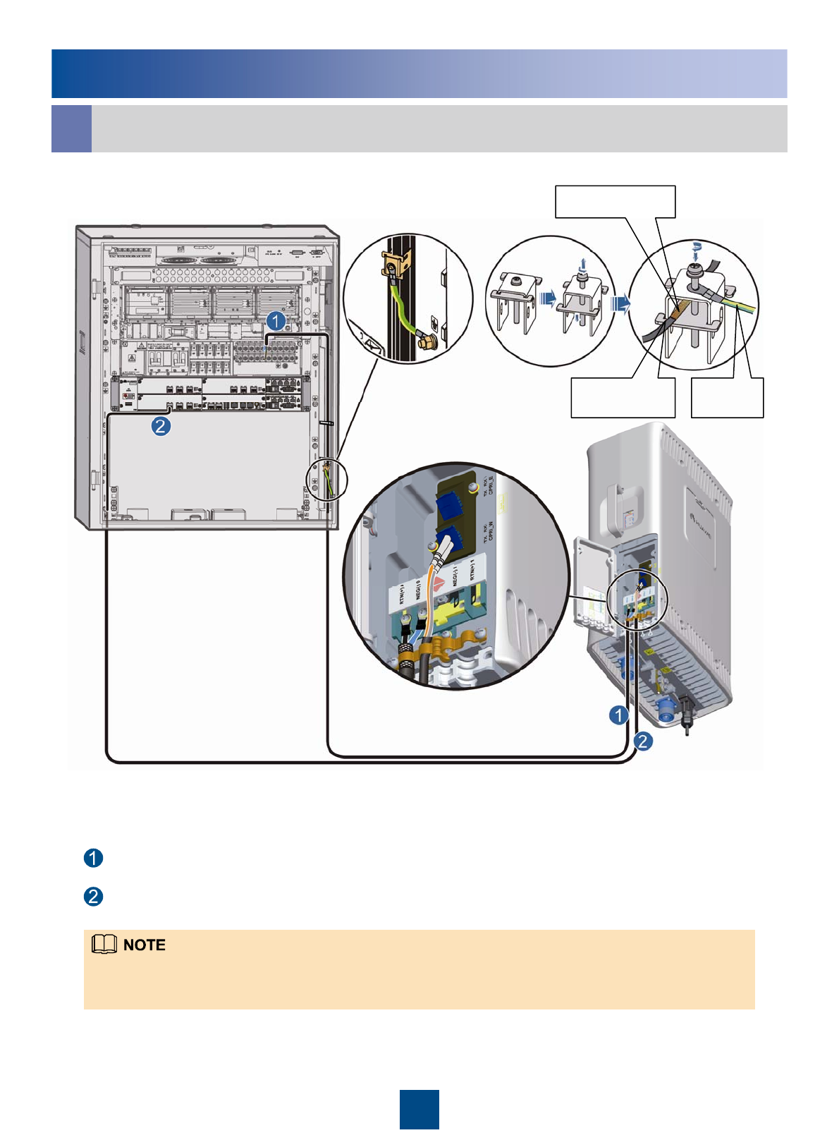
Installing the RRU Cables
gRRU+APM30/APM30H
RRU power cable
CPRI optical cable
1. The RRU power cable is connected to one group of the LOAD4 to LOAD9 terminals of the PDU.
2. Strip the jacket off the RRU power cable for a small part, press the exposed shielding layer on the strap, and
then connect the PGND cable on the strap to the nearest grounding bolt on the side in the APM30/APM30H.
19
RRU Power
cable
Shielding layer
PGND
cable
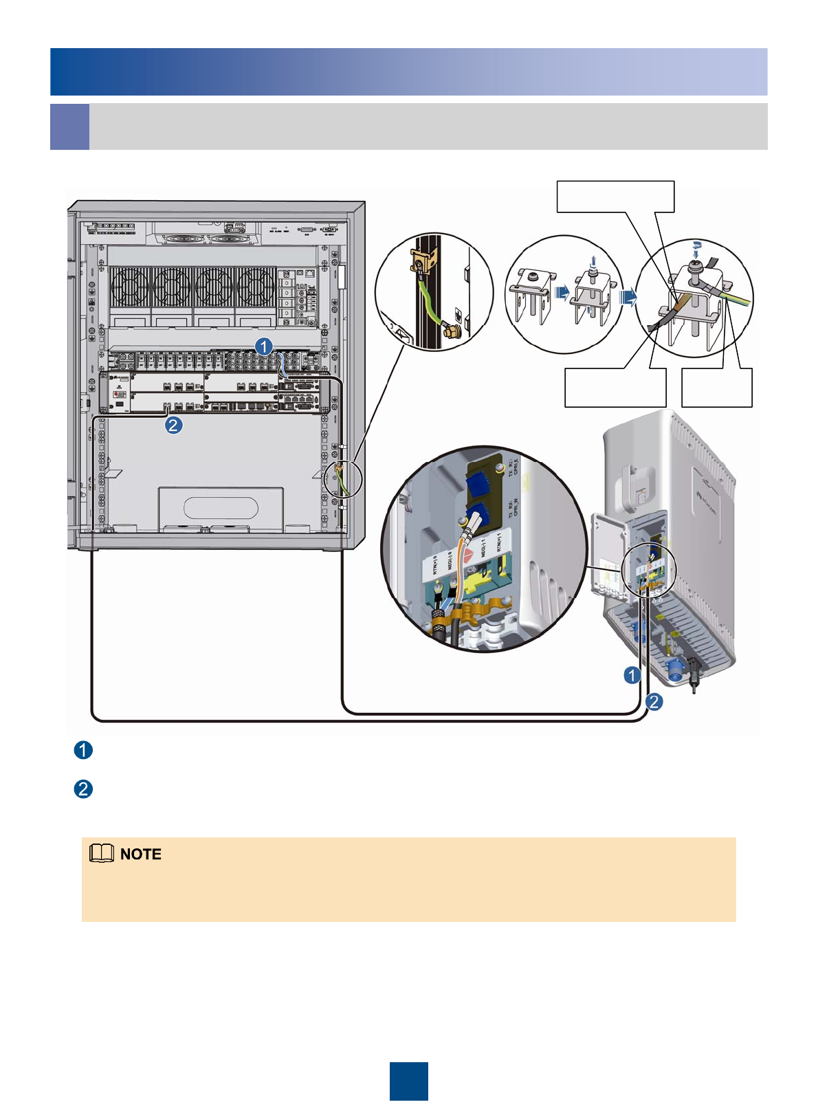
Installing the RRU Cables
hRRU+APM30(+24V)
RRU power cable
CPRI optical cable
1. Strip the jacket off the RRU power cable for a small part, press the exposed shielding layer on the strap, and
then connect the PGND cable on the strap to the nearest grounding bolt on the side in the APM30.
2. The RRU power cable is connected to one group of the LOAD0 to LOAD5 terminals of the DCDU-03C.
20
RRU Power
cable
Shielding layer
PGND
cable
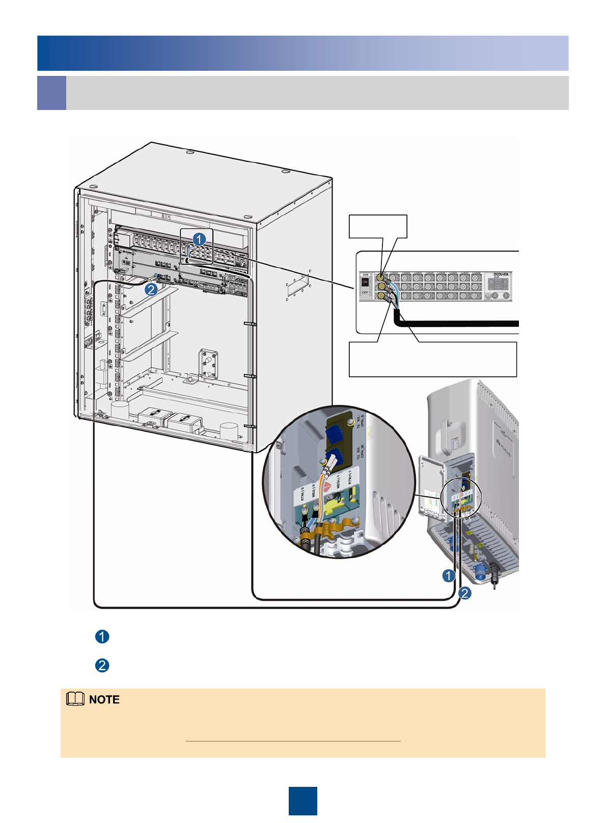
Installing the RRU Cables
iRRU+TMC
Shielding layer of the RRU
power cable
1. When connecting the RRU power cable to the DCDU-03C, you must add an OT terminal to the shielding layer.
Then, fix the OT terminal to the corresponding PGND terminal of the DCDU-03C. For details on how to add an OT
terminal, see pages 26 to 27 Adding OT Terminals to the Power Cable of the RRU.
2. The RRU power cable is connected to one group of the LOAD0 to LOAD5 terminals of the DCDU-03C.
21
LOAD0
RRU power cable
CPRI optical cable
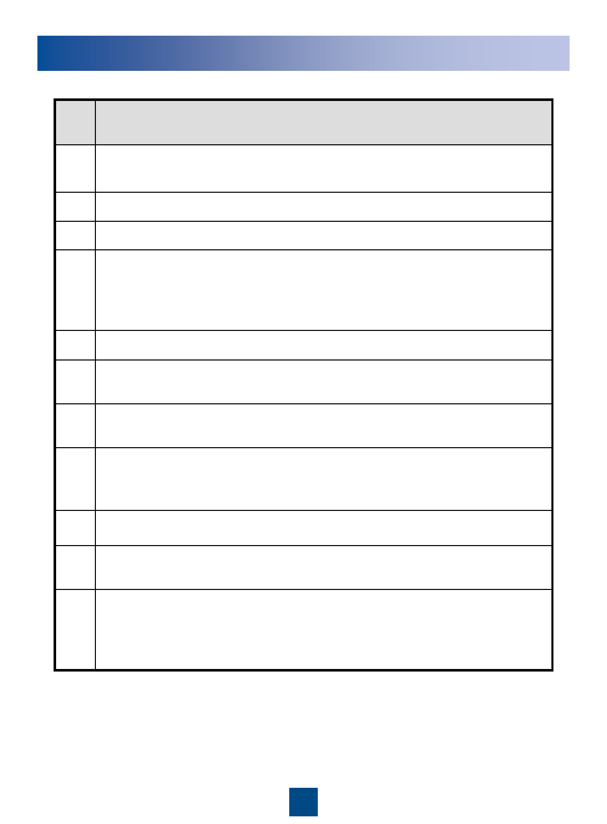
RRU Hardware Installation Checklist
The connectors of signal cables are intact.9
Set the power switch to OFF and check the input voltage (-48 V DC power supply:
-36 V DC to -57 V DC. AC power supply: 150 V AC to 300 V AC). Set the power
switch to ON and check the RUN LED (the RUN LED is ON for 1s and OFF for
1s).
11
All labels, tags, and nameplates are correct, legible, and complete. All the labels
at both ends of the cables, jumpers and feeders are legible.
10
The working grounding and protection grounding of the base station and the
lightning protection grounding of the building share one group of grounding
conductors.
8
The power cable and PGND cable are not short-circuited or reversely connected
and are not damaged or broken.
7
The lugs at both ends of the power cable or the PGND cable are securely
soldered or crimped.
6
No joint lies in the middle of the power cable or the PGND cable.5
Waterproof check: The empty cable troughs in the cabling cavity of the RRU are
waterproofed. The cover plate is tightly buckled on the cabling cavity of the RRU.
The RF ports that are not connected with RF cables are capped and
waterproofed.
4
The cover plate is fastened to the RRU cabling cavity.3
The RRU is properly installed.2
The position for each equipment conforms to the engineering design and meets
the space requirement. Sufficient space is reserved for equipment maintenance.
1
ItemsNo.
22
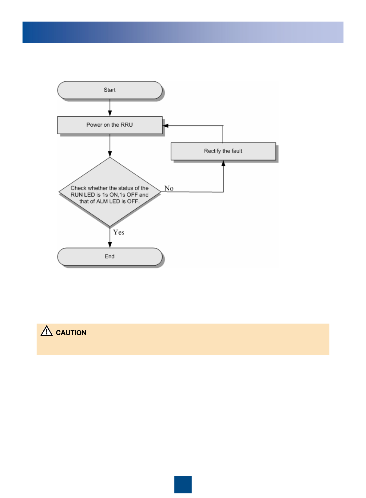
Powering On the RRU
The RRU should be powered on in 24 hours after being unpacked. The power off duration of the RRU cannot
exceed 24 hours during maintenance.
23
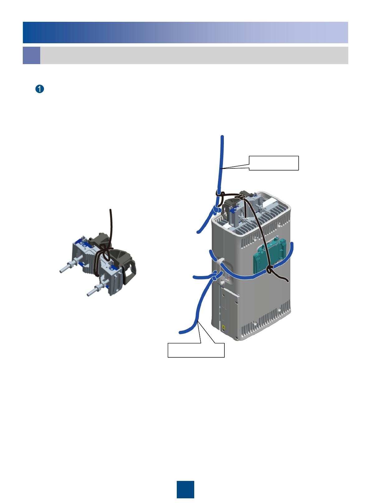
Reference
Lift the RRU and installation components to the tower.
a
Tie one end of a rope to the installation components and the other end to the rope for
binding the RRU.
Steering rope
Lifting rope
24
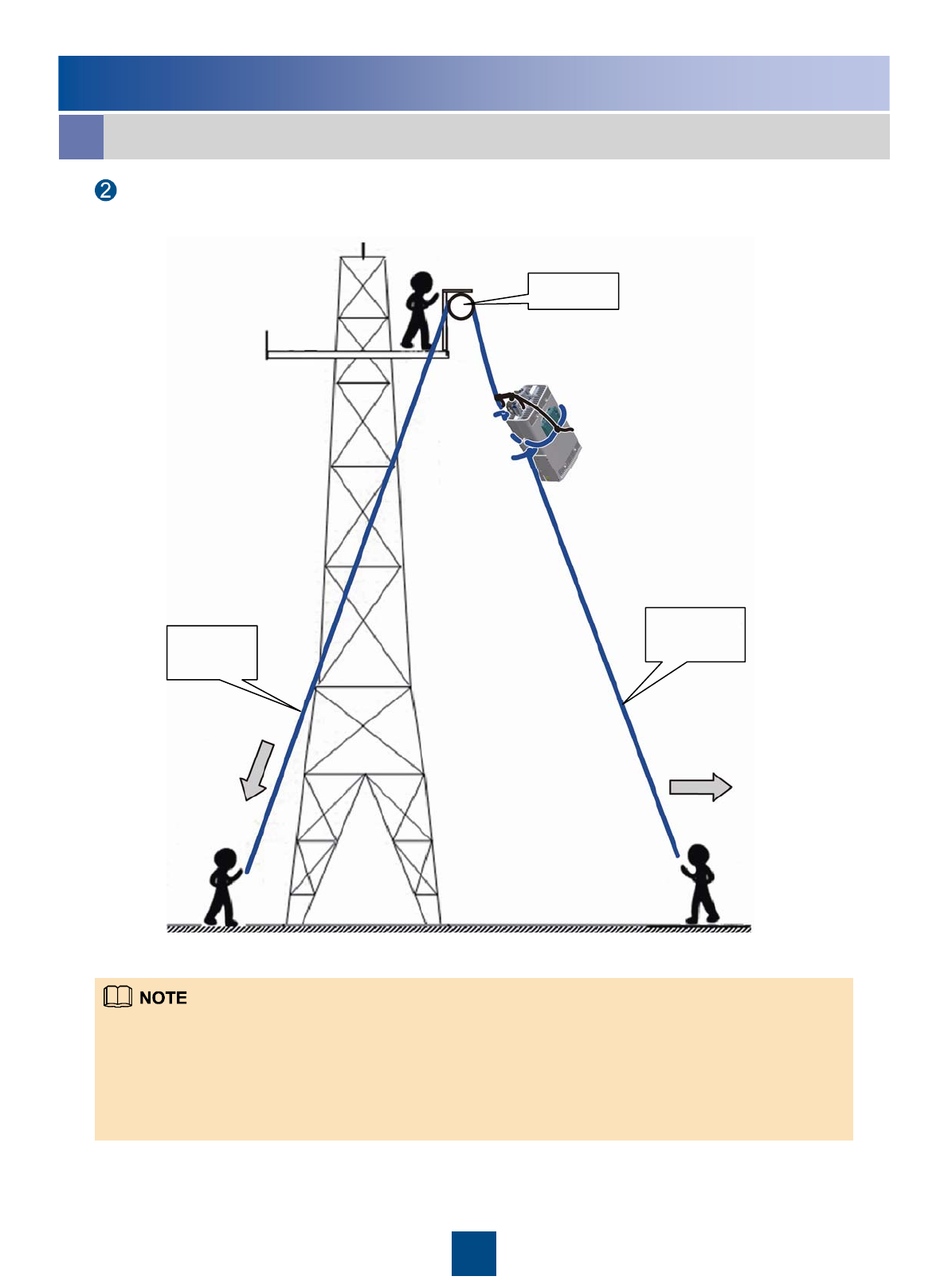
Reference
1. Installer A climbs onto the tower. Then, fixes the pulley to the support of the tower platform and leads the lifting
rope through the pulley.
2. Installer C uses a lifting rope to bind the RRU and installation components as shown in the preceding figure
and then ties a knot in the steering rope at the handle of the RRU.
3. Installer B pulls the lifting rope downwards, and at the same time, installer C pulls the steering rope away from
the tower to prevent the RRU and installation components from colliding with the tower.
4. Installers A holds the RRU and installation components and unties the ropes
Lift the RRU and installation components to the tower.
a
25
Lift the RRU and installation components to the tower.
A
BC
Steering
rope
Lifting
rope
Pulley
Reference
OT terminals on the power cable:
To assemble the OT terminals, perform the following steps:
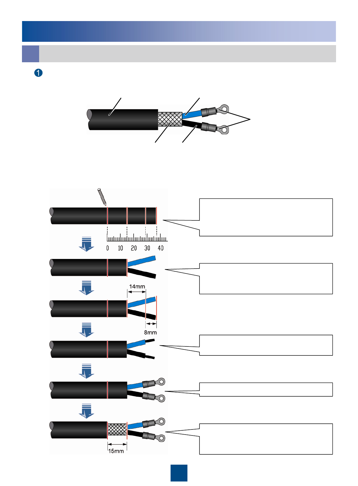
Adding OT Terminals to the Power Cable of the RRU
b
Determine lengths of power cables for
different operations according to the
scales on the inner side of the cover
plate of the cabling cavity.
Based on the determined length,
remove the jacket and shielding layer
off the power cable.
Remove the jacket of a specified
length from each wire.
Add an OT terminal to each wire.
Remove about 15 mm jacket off the
power cable to expose the shielding
layer.
26
-48V DC power cable
Shielding layer GND wire
-48V power wire
OT terminals
Reference
Adding OT Terminals to the Power Cable of the RRU
b
Assemble an OT terminal on the power cable at the end connecting to the power supply
device.
27
Heat-shrinkable tube PVC insulating tape OT terminal on the
shielding layer
Reference
Pin Assignment of the RRU AISG Extension cable
c
Brown
+24VTwisted pairWhite/brownX2.6X1.6
RS485 AGreenX2.5X1.5
RS485 BTwisted pairWhite/greenX2.3X1.3
Orange
DC Return ATwisted pairWhite/orangeX2.7X1.7
Blue
+12VTwisted pairWhite/blueX2.1X1.1
InstructionWire TypeWire ColorPin of the AISG female
connector
Pin of the AISG
male connector
Pin Assignment for the Wires of the RRU Alarm Cable
d
X9
X8
X7
X6
X5
X4
X3
X2
Cord End
Terminal
APM TX+BrownRS485_RX+X1.5
APM TX-Twisted pairWhite/brownRS485_RX-X1.3
APM RX+GreenRS485_TX+X1.8
APM RX-Twisted pairWhite/greenRS485_TX-X1.6
GNDOrangeGNDX1.4
SWITCH_INPUT1+Twisted pairWhite/orangeSWITCH_INPUT1+X1.7
GNDBlueGNDX1.4
SWITCH_INPUT0+Twisted pairWhite/blueSWITCH_INPUT0+X1.2
LabelWire TypeWire ColorPin NameDB9 waterproof
Connector
28

HUAWEI TECHNOLOGIES CO., LTD.
Huawei Industrial Base Bantian Longgang
Shenzhen 518129
People’s Republic of China
www.huawei.com
Issue: 01
Part Number: 31504691
Date: 2009-03-15