Huawei Technologies RRU3804B4 Distributed NodeB Remote Radio Unit User Manual User Guide
Huawei Technologies Co.,Ltd Distributed NodeB Remote Radio Unit User Guide
Contents
- 1. User Manual 1
- 2. User Manual 2
- 3. User Manual 3
User Manual 1

RRU3804
V100
User Guide
Issue 01
Date 2007-11-29
Part Number 31018637
Huawei Technologies Proprietary

Huawei Technologies Co., Ltd. provides customers with comprehensive technical support and service. For any
assistance, please contact our local office or company headquarters.
Huawei Technologies Co., Ltd.
Address: Huawei Industrial Base
Bantian, Longgang
Shenzhen 518129
People's Republic of China
Website: http://www.huawei.com
Email: support@huawei.com
Copyright © 2007 Huawei Technologies Co., Ltd. All rights reserved.
No part of this document may be reproduced or transmitted in any form or by any means without prior written
consent of Huawei Technologies Co., Ltd.
Trademarks and Permissions
and other Huawei trademarks are the property of Huawei Technologies Co., Ltd.
All other trademarks and trade names mentioned in this document are the property of their respective holders.
Notice
The information in this document is subject to change without notice. Every effort has been made in the
preparation of this document to ensure accuracy of the contents, but the statements, information, and
recommendations in this document do not constitute a warranty of any kind, express or implied.
Huawei Technologies Proprietary

Contents
About This Document.....................................................................................................................1
1 Safety Information.....................................................................................................................1-1
1.1 Safety Precautions...........................................................................................................................................1-1
1.2 Electricity Safety.............................................................................................................................................1-3
1.3 Inflammable Environment...............................................................................................................................1-5
1.4 Battery.............................................................................................................................................................1-6
1.5 Radiation.........................................................................................................................................................1-8
1.6 Working at Heights.........................................................................................................................................1-9
1.7 Mechanical Safety.........................................................................................................................................1-11
1.8 Others............................................................................................................................................................1-13
2 RRU3804 and SRXU Hardware................................................................................................2-1
2.1 RRU3804 Equipment......................................................................................................................................2-2
2.1.1 DBS3800 Product Family......................................................................................................................2-2
2.1.2 Appearance of the RRU3804.................................................................................................................2-5
2.1.3 LEDs on the RRU3804..........................................................................................................................2-6
2.1.4 Ports on the RRU3804............................................................................................................................2-7
2.1.5 Panels of the RRU3804..........................................................................................................................2-8
2.1.6 Engineering Specifications of the RRU3804.......................................................................................2-10
2.2 SRXU Equipment..........................................................................................................................................2-11
2.2.1 Appearance of the SRXU.....................................................................................................................2-11
2.2.2 LEDs on the SRXU..............................................................................................................................2-12
2.2.3 Ports on the SRXU...............................................................................................................................2-13
2.2.4 Panels of the SRXU..............................................................................................................................2-14
2.2.5 Engineering Specifications of the SRXU.............................................................................................2-15
2.3 RRU3804 Cables...........................................................................................................................................2-15
2.3.1 PGND Cable of the RRU3804.............................................................................................................2-16
2.3.2 Power Cable of the RRU3804..............................................................................................................2-17
2.3.3 AISG Multi-Wire Cable of the RRU3804/SRXU................................................................................2-18
2.3.4 AISG Extension Cable of the RRU3804/SRXU..................................................................................2-19
2.3.5 BBU3806-RRU/SRXU CPRI Optical Cable.......................................................................................2-20
2.3.6 BBU3806C-RRU/SRXU CPRI Optical Cable.....................................................................................2-21
2.3.7 RF Jumper of the RRU3804/SRXU.....................................................................................................2-23
RRU3804
User Guide Contents
Issue 01 (2007-11-29) Huawei Technologies Proprietary i

2.3.8 Boolean/RS485 Input Cable of the RRU3804.....................................................................................2-25
2.4 SRXU Cables................................................................................................................................................2-27
2.4.1 PGND Cable of the SRXU...................................................................................................................2-27
2.4.2 Power Cable of the SRXU...................................................................................................................2-28
2.4.3 AISG Multi-Wire Cable of the RRU3804/SRXU................................................................................2-28
2.4.4 AISG Extension Cable of the RRU3804/SRXU..................................................................................2-29
2.4.5 BBU3806-RRU/SRXU CPRI Optical Cable.......................................................................................2-30
2.4.6 RF Jumper of the RRU3804/SRXU.....................................................................................................2-32
3 Installing RRU3804 and SRXU Hardware.............................................................................3-1
3.1 Information About the Installation..................................................................................................................3-3
3.1.1 Installation Modes of the RRU3804 and SRXU....................................................................................3-3
3.1.2 Space Requirements of the RRU3804 and SRXU.................................................................................3-6
3.2 Procedure for Installing the RRU3804 and SRXU.......................................................................................3-10
3.3 Preparing for DBS3800 Installation..............................................................................................................3-11
3.3.1 Unpacking the DBS3800......................................................................................................................3-12
3.3.2 Tools and Instruments for DBS3800 Installation.................................................................................3-13
3.4 Installing the RRU3804 on the Ground or Rooftop......................................................................................3-14
3.4.1 Installing a Single RRU3804................................................................................................................3-14
3.4.2 Installing Two RRU3804s....................................................................................................................3-25
3.4.3 Installing Three RRU3804s..................................................................................................................3-39
3.5 Installing the RRU3804 on the Tower..........................................................................................................3-57
3.5.1 Assembling the Parts of the RRU3804................................................................................................3-57
3.5.2 Lifting the Assembled RRU3804.........................................................................................................3-61
3.5.3 Installing the Assembled RRU3804 on the Tower...............................................................................3-62
3.6 Installing the SRXU......................................................................................................................................3-65
3.6.1 Installing the SRXU on a Single RRU3804.........................................................................................3-66
3.6.2 Installing the SRXUs on the Two RRU3804s......................................................................................3-69
3.6.3 Installing the SRXUs on the Three RRU3804s....................................................................................3-74
3.7 Installing RRU3804 and SRXU Cables........................................................................................................3-78
3.7.1 Cabling Specifications for the NodeB..................................................................................................3-78
3.7.2 Connections of RRU3804 and SRXU Cables......................................................................................3-80
3.7.3 Installing the PGND Cable of the RRU3804/SRXU...........................................................................3-84
3.7.4 Installing the -48 V DC Power Cable of the RRU3804/SRXU...........................................................3-85
3.7.5 Installing the RF Jumper of the RRU3804/SRXU...............................................................................3-92
3.7.6 Installing the AISG Multi-Wire Cable of the RRU3804/SRXU..........................................................3-94
3.7.7 Installing the AISG Extension Cable of the RRU3804/SRXU............................................................3-94
3.7.8 Installing the Boolean/RS485 Input Cable of the RRU3804...............................................................3-94
3.7.9 Opening and Closing the Cover Plate of the RRU3804 Cabling Cavity.............................................3-96
3.7.10 Opening and Closing the Cover Plate of the SRXU Cabling Cavity.................................................3-99
3.8 Checking RRU3804 and SRXU Hardware Installation..............................................................................3-101
3.8.1 Checking the Power-On Status of the RRU3804 and SRXU.............................................................3-102
3.8.2 Checklist for RRU3804 and SRXU Hardware Installation................................................................3-103
Contents
RRU3804
User Guide
ii Huawei Technologies Proprietary Issue 01 (2007-11-29)

3.8.3 Checklist for Field Cleanliness of RRU3804 and SRXU Installation...............................................3-105
3.9 Installing the Housing of the RRU3804 and SRXU...................................................................................3-105
4 Maintaining RRU3804 and SRXU Hardware........................................................................4-1
4.1 Equipment Maintenance Items for the DBS3800...........................................................................................4-2
4.2 Powering On/Off the RRU3804/SRXU..........................................................................................................4-2
4.2.1 Powering on the RRU3804/SRXU.........................................................................................................4-2
4.2.2 Powering off the RRU3804/SRXU........................................................................................................4-4
4.3 Replacing an RRU3804...................................................................................................................................4-4
4.4 Replacing an SRXU........................................................................................................................................4-6
4.5 Replacing RRU3804 and SRXU Cables.........................................................................................................4-7
4.5.1 Replacing the CPRI Optical Cable.........................................................................................................4-7
4.5.2 Replacing the RF Jumper of the RRU/SRXU........................................................................................4-8
4.5.3 Replacing the AISG Multi-Wire Cable of the RRU/SRXU.................................................................4-10
4.5.4 Replacing the AISG Extension Cable of the RRU/SRXU...................................................................4-11
Index.................................................................................................................................................i-1
RRU3804
User Guide Contents
Issue 01 (2007-11-29) Huawei Technologies Proprietary iii

Figures
Figure 1-1 Wearing an ESD wrist strap...............................................................................................................1-5
Figure 1-2 Lifting a weight................................................................................................................................1-10
Figure 1-3 Slant angle........................................................................................................................................1-11
Figure 1-4 One meter higher than the eave........................................................................................................1-11
Figure 2-1 Function modules of the DBS3800....................................................................................................2-2
Figure 2-2 RRU3804............................................................................................................................................2-5
Figure 2-3 Panels of the RRU3804......................................................................................................................2-9
Figure 2-4 SRXU................................................................................................................................................2-12
Figure 2-5 Panels of the SRXU..........................................................................................................................2-14
Figure 2-6 PGND cable......................................................................................................................................2-16
Figure 2-7 2-hole terminal..................................................................................................................................2-16
Figure 2-8 –48 V DC power cable.....................................................................................................................2-17
Figure 2-9 AISG multi-wire cable......................................................................................................................2-18
Figure 2-10 AISG extension cable.....................................................................................................................2-19
Figure 2-11 CPRI optical cable..........................................................................................................................2-20
Figure 2-12 Connecting the CPRI optical cable in 1 x 1 configuration (no TX diversity)................................2-21
Figure 2-13 Connecting the CPRI optical cable in 3 x 1 configuration (no TX diversity)................................2-21
Figure 2-14 CPRI optical cable..........................................................................................................................2-22
Figure 2-15 Connecting the CPRI optical cable in 1 x 1 configuration (no TX diversity)................................2-22
Figure 2-16 Connecting the CPRI optical cable in 3 x 1 configuration (no TX diversity)................................2-23
Figure 2-17 Antenna jumper..............................................................................................................................2-23
Figure 2-18 Interconnect jumper........................................................................................................................2-24
Figure 2-19 Boolean/RS485 input cable............................................................................................................2-26
Figure 2-20 PGND cable....................................................................................................................................2-27
Figure 2-21 2-hole terminal................................................................................................................................2-28
Figure 2-22 DC power cable..............................................................................................................................2-28
Figure 2-23 AISG multi-wire cable....................................................................................................................2-29
Figure 2-24 AISG extension cable.....................................................................................................................2-30
Figure 2-25 CPRI optical cable..........................................................................................................................2-31
Figure 2-26 Connecting the CPRI optical cable in 1 x 1 configuration (no TX diversity)................................2-31
Figure 2-27 Connecting the CPRI optical cable in 3 x 1 configuration (no TX diversity)................................2-32
Figure 2-28 Antenna jumper..............................................................................................................................2-32
Figure 2-29 Interconnect jumper........................................................................................................................2-33
RRU3804
User Guide Figures
Issue 01 (2007-11-29) Huawei Technologies Proprietary v

Figure 3-1 Installation modes of one RRU3804..................................................................................................3-3
Figure 3-2 Installation modes of one RRU3804 with one SRXU........................................................................3-4
Figure 3-3 Installation modes of two RRU3804s.................................................................................................3-4
Figure 3-4 Installation modes of two RRU3804s with two SRXUs.................................................................... 3-5
Figure 3-5 Installation modes of three RRU3804s...............................................................................................3-5
Figure 3-6 Installation modes of three RRU3804s with three SRXUs................................................................ 3-6
Figure 3-7 Recommended space requirements of one RRU3804 with and without the SRXU (unit: mm)........ 3-7
Figure 3-8 Minimal space requirements of one RRU3804 with and without the SRXU (unit: mm)...................3-8
Figure 3-9 Space requirements of two combined RRU3804s (unit: mm) ...........................................................3-8
Figure 3-10 Recommended space requirements of multiple RRU3804s with and without the SRXUs (unit: mm)
...............................................................................................................................................................................3-9
Figure 3-11 Minimal space requirements of multiple RRU3804s with and without the SRXUs (unit: mm)....3-10
Figure 3-12 Mounting the upper fixture assembly.............................................................................................3-15
Figure 3-13 Measuring L1 and L2.....................................................................................................................3-16
Figure 3-14 Holes in the multi-purpose attachment plate..................................................................................3-16
Figure 3-15 Securing the multi-purpose attachment plate on the mounting plate.............................................3-17
Figure 3-16 Installing the third pole fixture.......................................................................................................3-17
Figure 3-17 Installing the mounting plate..........................................................................................................3-18
Figure 3-18 Mounting the lower fixture assembly.............................................................................................3-19
Figure 3-19 Determining the anchor points.......................................................................................................3-20
Figure 3-20 Drilling holes and installing the expansion bolt assembly ............................................................3-20
Figure 3-21 Securing the mounting plate...........................................................................................................3-21
Figure 3-22 One RRU3804 in ordinary mode and the other in reverse mode...................................................3-22
Figure 3-23 Securing the attachment plate.........................................................................................................3-23
Figure 3-24 Installing the module......................................................................................................................3-24
Figure 3-25 Securing the module.......................................................................................................................3-25
Figure 3-26 Holes in the multi-purpose attachment plate..................................................................................3-26
Figure 3-27 Securing the multi-purpose attachment plate at the bottom of the second mounting plate............3-26
Figure 3-28 Installing the second mounting plate..............................................................................................3-27
Figure 3-29 Securing the second mounting plate on the first one......................................................................3-28
Figure 3-30 Installing the second mounting plate..............................................................................................3-29
Figure 3-31 Securing the second mounting plate...............................................................................................3-29
Figure 3-32 Holes in the multi-purpose attachment plate..................................................................................3-30
Figure 3-33 Securing the multi-purpose attachment plate at the bottom of the second mounting plate............3-30
Figure 3-34 Installing the second mounting plate..............................................................................................3-31
Figure 3-35 Securing the second mounting plate on the first one......................................................................3-32
Figure 3-36 Removing the plastic housing.........................................................................................................3-33
Figure 3-37 Installing the module in reverse mode in the housing....................................................................3-34
Figure 3-38 Securing the attachment plate on the module in reverse mode......................................................3-34
Figure 3-39 Installing the first module...............................................................................................................3-35
Figure 3-40 Securing the first module................................................................................................................3-36
Figure 3-41 Securing the attachment plate on the module in ordinary mode....................................................3-37
Figure 3-42 Installing the second module..........................................................................................................3-37
Figures
RRU3804
User Guide
vi Huawei Technologies Proprietary Issue 01 (2007-11-29)

Figure 3-43 Securing the second module...........................................................................................................3-38
Figure 3-44 Rear-mounted RRU3804s with the cabling cavities on the same side...........................................3-39
Figure 3-45 Top view of the three modules using the side-mounted installation method.................................3-40
Figure 3-46 Top view of the three modules using the hybrid installation method.............................................3-40
Figure 3-47 Holes in the multi-purpose attachment plate..................................................................................3-41
Figure 3-48 Securing the multi-purpose attachment plate at the bottom of the second mounting plate............3-41
Figure 3-49 Installing the second mounting plate..............................................................................................3-42
Figure 3-50 Securing the second mounting plate on the first one......................................................................3-43
Figure 3-51 Installing the third mounting plate..................................................................................................3-44
Figure 3-52 Securing the third mounting plate on the first one.........................................................................3-45
Figure 3-53 Holes in the multi-purpose attachment plate..................................................................................3-45
Figure 3-54 Securing the multi-purpose attachment plate at the bottom of the second mounting plate............3-46
Figure 3-55 Installing the second mounting plate..............................................................................................3-46
Figure 3-56 Securing the second mounting plate on the first one......................................................................3-47
Figure 3-57 Installing the third mounting plate..................................................................................................3-48
Figure 3-58 Securing the third mounting plate on the first one.........................................................................3-49
Figure 3-59 Securing the attachment plate on the first module..........................................................................3-50
Figure 3-60 Installing the first module...............................................................................................................3-51
Figure 3-61 Securing the first module................................................................................................................3-52
Figure 3-62 Removing the plastic housing.........................................................................................................3-52
Figure 3-63 Installing the module in reverse mode in the housing....................................................................3-53
Figure 3-64 Securing the attachment plate on the module in reverse mode......................................................3-53
Figure 3-65 Installing the second module..........................................................................................................3-54
Figure 3-66 Securing the second module...........................................................................................................3-55
Figure 3-67 Installing the third module..............................................................................................................3-56
Figure 3-68 Securing the third module...............................................................................................................3-57
Figure 3-69 Securing the attachment plate.........................................................................................................3-58
Figure 3-70 Holes in the multi-purpose attachment plate..................................................................................3-58
Figure 3-71 Securing the multi-purpose attachment plate.................................................................................3-59
Figure 3-72 Installing a pole fixture...................................................................................................................3-59
Figure 3-73 Assembling the module and mounting plate..................................................................................3-60
Figure 3-74 Securing the module and mounting plate.......................................................................................3-61
Figure 3-75 Assembled RRU3804 tied with the rope........................................................................................3-61
Figure 3-76 Mounting the upper fixture assembly.............................................................................................3-62
Figure 3-77 Measuring L1 and L2.....................................................................................................................3-63
Figure 3-78 Installing the assembled RRU3804................................................................................................3-64
Figure 3-79 Mounting the lower fixture assembly.............................................................................................3-65
Figure 3-80 SRXU installed on the single RRU3804........................................................................................3-66
Figure 3-81 Removing the plastic housing.........................................................................................................3-67
Figure 3-82 Securing the connecting boards......................................................................................................3-67
Figure 3-83 Securing the attachment plate on the SRXU..................................................................................3-68
Figure 3-84 Installing the SRXU........................................................................................................................3-68
RRU3804
User Guide Figures
Issue 01 (2007-11-29) Huawei Technologies Proprietary vii

Figure 3-85 Securing the SRXU........................................................................................................................3-69
Figure 3-86 SRXUs installed on the two RRU3804s.........................................................................................3-70
Figure 3-87 Removing the plastic housings.......................................................................................................3-70
Figure 3-88 Securing the connecting boards on the RRU3804 module in ordinary mode................................3-71
Figure 3-89 Securing the attachment plate on the first SRXU...........................................................................3-71
Figure 3-90 Installing the first SRXU................................................................................................................3-72
Figure 3-91 Securing the first SRXU.................................................................................................................3-73
Figure 3-92 Removing the plastic housings.......................................................................................................3-73
Figure 3-93 SRXUs installed on the two rear-mounted RRU3804s..................................................................3-74
Figure 3-94 SRXUs installed on the three RRU3804s.......................................................................................3-75
Figure 3-95 Removing the plastic housings.......................................................................................................3-75
Figure 3-96 Securing the connecting boards......................................................................................................3-76
Figure 3-97 Installing the third SRXU...............................................................................................................3-77
Figure 3-98 Securing the third SRXU................................................................................................................3-77
Figure 3-99 Cable connections of one RRU3804 without the SRXU................................................................3-81
Figure 3-100 Cable connections of one RRU3804 with the SRXU...................................................................3-82
Figure 3-101 Cable connections of multiple RRU3804s without the SRXUs...................................................3-83
Figure 3-102 Cable connections of multiple RRU3804s with the SRXUs........................................................3-83
Figure 3-103 Connecting the PGND cable (1)...................................................................................................3-84
Figure 3-104 Connecting the PGND cable (2)...................................................................................................3-85
Figure 3-105 Connecting the OT terminal.........................................................................................................3-85
Figure 3-106 Power cable with two OT terminals.............................................................................................3-86
Figure 3-107 Determining lengths of power cable for different operation........................................................3-86
Figure 3-108 Stripping the cable........................................................................................................................3-87
Figure 3-109 Two OT terminals on the power cable.........................................................................................3-87
Figure 3-110 Removing the jacket from the power cable..................................................................................3-88
Figure 3-111 Cable troughs in the cabling cavity..............................................................................................3-88
Figure 3-112 Opening the cover.........................................................................................................................3-89
Figure 3-113 Twisting the shielding layer into one strand.................................................................................3-90
Figure 3-114 Crimping the shielding layer and the PGND cable......................................................................3-91
Figure 3-115 Power cable with the heat-shrinkable tube...................................................................................3-91
Figure 3-116 Waterproofed joints......................................................................................................................3-93
Figure 3-117 Cable troughs in the cabling cavity..............................................................................................3-95
Figure 3-118 Loosening the six captive screws.................................................................................................3-97
Figure 3-119 Opening the cover plate................................................................................................................3-97
Figure 3-120 Tightening the screws...................................................................................................................3-98
Figure 3-121 Loosening the six captive screws.................................................................................................3-99
Figure 3-122 Opening the cover plate..............................................................................................................3-100
Figure 3-123 Tightening the screws.................................................................................................................3-101
Figure 3-124 Installing the housing..................................................................................................................3-106
Figure 3-125 Securing the housing..................................................................................................................3-106
Figures
RRU3804
User Guide
viii Huawei Technologies Proprietary Issue 01 (2007-11-29)

Tables
Table 2-1 LEDs on the RRU3804........................................................................................................................ 2-6
Table 2-2 Power supply port on the RRU3804.................................................................................................... 2-7
Table 2-3 Transmission ports on the RRU3804...................................................................................................2-7
Table 2-4 Alarm port on the RRU3804................................................................................................................2-7
Table 2-5 Specifications for the alarm port on the RRU3804..............................................................................2-8
Table 2-6 Other ports on the RRU3804................................................................................................................2-8
Table 2-7 Ports and LEDs on the panels of the RRU3804.................................................................................2-10
Table 2-8 Power input to the RRU3804.............................................................................................................2-11
Table 2-9 LEDs on the SRXU............................................................................................................................2-12
Table 2-10 Power supply ports on the SRXU....................................................................................................2-13
Table 2-11 Transmission ports on the SRXU.....................................................................................................2-13
Table 2-12 Other ports on the SRXU.................................................................................................................2-13
Table 2-13 Ports and LEDs on the panels of the SRXU....................................................................................2-15
Table 2-14 Pin assignment for the wires of the –48 V DC power cable (North American Standard)...............2-17
Table 2-15 Pin assignment for the wires of the –48 V DC power cable (European Standard)..........................2-17
Table 2-16 Pin assignment for the wires of the AISG multi-wire cable............................................................2-18
Table 2-17 Pin assignment for the wires of the AISG extension cable..............................................................2-19
Table 2-18 Pin assignment for the fiber tails......................................................................................................2-20
Table 2-19 Pin assignment for the fiber tails of the CRPI optical cable............................................................2-22
Table 2-20 RF jumper connections of the RRU3804.........................................................................................2-24
Table 2-21 Pin assignment for the wires of the Boolean/RS485 input cable.....................................................2-26
Table 2-22 Pin assignment for the wires of the DC power cable.......................................................................2-28
Table 2-23 Pin assignment for the wires of the AISG multi-wire cable............................................................2-29
Table 2-24 Pin assignment for the wires of the AISG extension cable..............................................................2-30
Table 2-25 Pin assignment for the fiber tails......................................................................................................2-31
Table 3-1 Tools and instruments........................................................................................................................3-13
Table 3-2 Connecting the antenna jumper to the appropriate RF port...............................................................3-92
Table 3-3 Checklist for equipment installation................................................................................................3-103
Table 3-4 Checklist for the power cable and PGND cable connections...........................................................3-104
Table 3-5 Checklist for signal cable connections.............................................................................................3-104
Table 3-6 Checklist for field cleanliness..........................................................................................................3-105
Table 4-1 Equipment maintenance items for the DBS3800.................................................................................4-2
Table 4-2 LEDs on the RRU3804........................................................................................................................ 4-3
RRU3804
User Guide Tables
Issue 01 (2007-11-29) Huawei Technologies Proprietary ix

Table 4-3 LEDs on the SRXU..............................................................................................................................4-3
Tables
RRU3804
User Guide
x Huawei Technologies Proprietary Issue 01 (2007-11-29)
About This Document
Purpose
This document describes the RRU3804 hardware and provides instructions in hardware
installation, cable connections, hardware installation check, and hardware maintenance.
Product Version
The following table lists the product version related to this document.
Product Name Product Version
RRU3804 V100R009
Intended Audience
This document is intended for:
lNodeB installers
lSystem engineers
lSite maintainers
Change History
For changes in the document, refer to Changes in RRU3804 User Guide.
Organization
1 Safety Information
2 RRU3804 and SRXU Hardware
This describes the RRU3804 equipment, SRXU equipment, and related cables.
3 Installing RRU3804 and SRXU Hardware
This describes how to install the hardware, route the cables, and check the hardware installation
of the RRU3804 and SRXU.
4 Maintaining RRU3804 and SRXU Hardware
RRU3804
User Guide About This Document
Issue 01 (2007-11-29) Huawei Technologies Proprietary 1
After the RRU3804 and SRXU are deployed, accepted, and put into use, routine maintenance
is performed to ensure the functionality of the modules.
Conventions
1. Symbol Conventions
The following symbols may be found in this document. They are defined as follows
Symbol Description
DANGER
Indicates a hazard with a high level of risk that, if not avoided,
will result in death or serious injury.
WARNING
Indicates a hazard with a medium or low level of risk which, if
not avoided, could result in minor or moderate injury.
CAUTION
Indicates a potentially hazardous situation that, if not avoided,
could cause equipment damage, data loss, and performance
degradation, or unexpected results.
TIP Indicates a tip that may help you solve a problem or save your
time.
NOTE Provides additional information to emphasize or supplement
important points of the main text.
2. General Conventions
Convention Description
Times New Roman Normal paragraphs are in Times New Roman.
Boldface Names of files,directories,folders,and users are in boldface. For
example,log in as user root .
Italic Book titles are in italics.
Courier New Terminal display is in Courier New.
3. Command Conventions
Convention Description
Boldface The keywords of a command line are in boldface.
Italic Command arguments are in italic.
[ ] Items (keywords or arguments) in square brackets [ ] are optional.
About This Document
RRU3804
User Guide
2 Huawei Technologies Proprietary Issue 01 (2007-11-29)
Convention Description
{x | y | ...} Alternative items are grouped in braces and separated by vertical
bars.One is selected.
[ x | y | ... ] Optional alternative items are grouped in square brackets and
separated by vertical bars.One or none is selected.
{ x | y | ... } * Alternative items are grouped in braces and separated by vertical
bars.A minimum of one or a maximum of all can be selected.
[ x | y | ... ] * Alternative items are grouped in braces and separated by vertical
bars.A minimum of zero or a maximum of all can be selected.
4. GUI Conventions
Convention Description
Boldface Buttons,menus,parameters,tabs,window,and dialog titles are in
boldface. For example,click OK.
>Multi-level menus are in boldface and separated by the ">" signs.
For example,choose File > Create > Folder .
5. Keyboard Operation
Convention Description
Key Press the key.For example,press Enter and press Tab.
Key1+Key2 Press the keys concurrently.For example,pressing Ctrl+Alt+A
means the three keys should be pressed concurrently.
Key1,Key2 Press the keys in turn.For example,pressing Alt,A means the two
keys should be pressed in turn.
6. Mouse Operation
Action Description
Click Select and release the primary mouse button without moving the
pointer.
Double-click Press the primary mouse button twice continuously and quickly
without moving the pointer.
Drag Press and hold the primary mouse button and move the pointer
to a certain position.
RRU3804
User Guide About This Document
Issue 01 (2007-11-29) Huawei Technologies Proprietary 3
1 Safety Information
1.1 Safety Precautions
This section describes certain safety precautions. Read and follow these safety precautions
before installing, operating, and maintaining Huawei devices.This manual can also help to
choose the measurement device and testing device.
Following All Safety Precautions
Before any operation, read the instructions and precautions in this document carefully to
minimize the possibility of accidents.
The Danger, Caution, and Note items in the documents do not cover all the safety precautions
that must be followed. They only provide the generic safety precautions for operations.
Symbols
DANGER
This symbol indicates that casualty or serious accident may occur if you ignore the safety
instruction.
CAUTION
This symbol indicates that serious or major injury may occur if you ignore the safety
instruction.
NOTE
This symbol indicates that the operation may be easier if you pay attention to the safety instruction.
RRU3804
User Guide 1 Safety Information
Issue 01 (2007-11-29) Huawei Technologies Proprietary 1-1

Complying with the Local Safety Regulations
When operating the device, comply with the local safety regulations. The safety precautions
provided in the documents are supplementary. You must comply with the local safety
regulations.
General Installation Requirements
The personnel in charge of installation and maintenance must be trained and master the correct
operating methods and safety precautions before beginning work.
The rules for installing and maintaining the device are as follows:
lOnly the trained and qualified personnel can install, operate and maintain the device.
lOnly the qualified specialists are allowed to remove the safety facilities, and repair the
device.
lAny replacement of the device or part of the device (including the software) or any change
made to the device must be performed by qualified or authorized personnel of Huawei.
lAny fault or error that might cause safety problems must be reported immediately to the
personnel in charge.
Grounding Requirements
The following requirements are applicable to the device to be grounded:
lGround the device before installation and remove the ground cable after uninstallation.
lDo not operate the device in the absence of a ground conductor. Do not damage the ground
conductor.
lThe unit (or system) must be permanently connected to the protection ground before
operation. Check the electrical connection of the device before operation and ensure that
the device is reliably grounded.
Safety of Personnel
Ensure the following:
lWhen lightning strikes, do not operate the device and cables.
lWhen lightning strikes, unplug the AC power connector. Do not use the fixed terminal or
touch the terminal or antenna connector.
NOTE
The previous two requirements are suitable for the wireless fixed terminal.
lTo prevent electric shock, do not connect safety extra-low voltage (SELV) circuits to
telecommunication network voltage (TNV) circuits.
lTo prevent laser radiation from injuring your eyes, never look into the optical fiber outlet
with unaided eyes.
lTo prevent electric shock and burns, wear the electrostatic discharge (ESD) clothing, gloves
and wrist strap, and remove conductors such as jewelry and watch before operation.
1 Safety Information
RRU3804
User Guide
1-2 Huawei Technologies Proprietary Issue 01 (2007-11-29)
Device Safety
lBefore operation, the device must be secured on the floor or other fixed objects, such as
the walls and the mounting racks.
lDo not block ventilation openings while the system is running.
lWhen installing the panel, tighten the screw with the tool.
1.2 Electricity Safety
High Voltage
DANGER
lThe high voltage power supply provides power for running the system. Direct contact
with the high voltage power supply or contact through damp objects may result in fatal
danger.
lNon-standard and improper high voltage operations may result in fire and electric shock.
lThe personnel who install the AC facility must be qualified to perform operations on high
voltage and AC power supply facilities.
lWhen installing the AC power supply facility, follow the local safety regulations.
lWhen operating the AC power supply facility, follow the local safety regulations.
lWhen operating the high voltage and AC power supply facilities, use the specific tools
instead of common tools.
lWhen the operation is performed in a damp environment, ensure that water is kept off the
device. If the cabinet is damp or wet, shut down the power supply immediately.
Thunderstorm
The following requirements are suitable only for the wireless base station or the device with an
antenna or GPS antenna.
DANGER
In a thunderstorm, do not perform operations on high voltage and AC power supply facilities
or on a steel tower and mast.
RRU3804
User Guide 1 Safety Information
Issue 01 (2007-11-29) Huawei Technologies Proprietary 1-3
High Electrical Leakage
CAUTION
Ground the device before powering on the device. Otherwise, the personnel and device are
in danger.
If the "high electrical leakage" flag is stuck to the power terminal of the device, you must ground
the device before powering it on.
Power Cable
CAUTION
Do not install and remove the power cable with a live line. Transient contact between the
core of the power cable and the conductor may generate electric arc or spark, which may
cause fire or eye injury.
lBefore installing or removing the power cable, turn off the power switch.
lBefore connecting the power cable, ensure that the power cable and label comply with the
requirements of the actual installation.
Fuse
CAUTION
To ensure that the system runs safely, when a fuse blows, replace it with a fuse of the same
type and specifications.
Electrostatic Discharge
CAUTION
The static electricity generated by the human body may damage the electrostatic sensitive
components on the circuit board, such as the large-scale integrated circuit (LIC).
In the following situations, the human body generates a static electromagnetic field:
lMovement of body parts
lClothes friction
lFriction between shoes and the ground
1 Safety Information
RRU3804
User Guide
1-4 Huawei Technologies Proprietary Issue 01 (2007-11-29)
lHolding plastic in hand
The static electromagnetic field will remain within the human body for a long time.
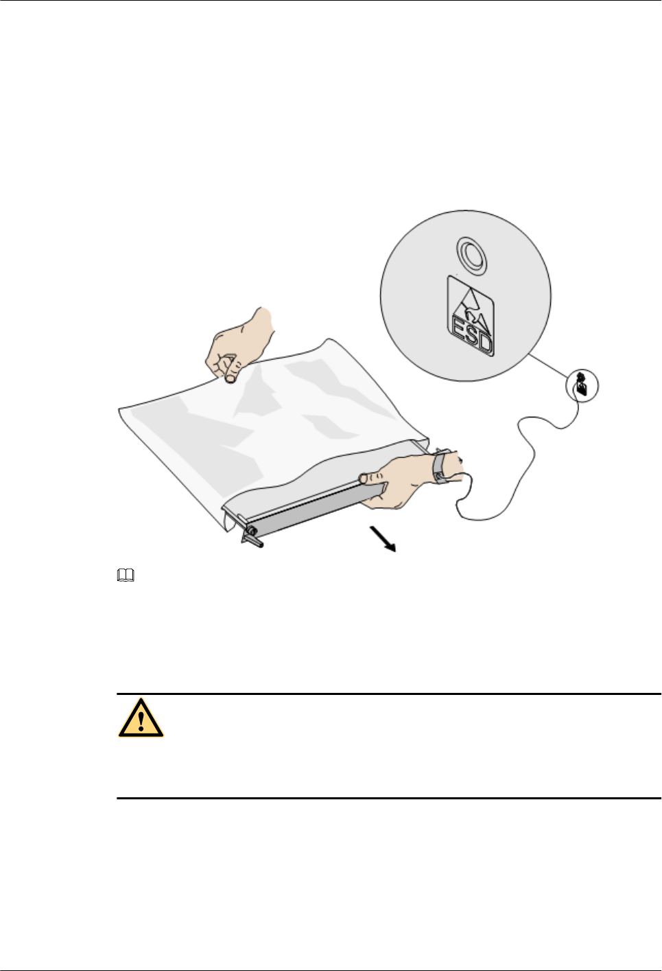
Before contacting the device, plug boards, circuit boards, and application specific integrated
circuits (ASICs), wear a grounded ESD wrist strap. It can prevent the sensitive components from
being damaged by the static electricity in the human body.
Figure 1-1shows how to wear an ESD wrist strap.
Figure 1-1 Wearing an ESD wrist strap
NOTE
For the GSM dual density base station,you need not wear an ESD wrist strap.
1.3 Inflammable Environment
DANGER
Do not place the device in the environment that has inflammable and explosive air or fog.
Do not perform any operation in this environment.
Any operation of the electrical device in the inflammable environment causes danger.
RRU3804
User Guide 1 Safety Information
Issue 01 (2007-11-29) Huawei Technologies Proprietary 1-5
1.4 Battery
Storage Battery
DANGER
Before handling the storage battery, read the safety precautions for the handling and
connection of the storage battery.
Incorrect operation of storage batteries may cause danger. During operation, ensure the
following:
lPrevent any short-circuit.
lPrevent the electrolyte from overflowing and leakage.
Electrolyte overflow may damage the device. It will corrode the metal parts and the circuit
boards, and ultimately damage the device and cause short-circuit of the circuit boards.
General Operations
Before installing and maintaining the storage battery, ensure the following:
lUse special insulation tools.
lUse eye protection devices and operate with care.
lWear rubber gloves and an apron in case of an electrolyte overflow.
lAlways keep the battery upright when moving. Do not place the battery upside down or tilt
it.
Short-Circuit
DANGER
Short-circuit of the battery may cause injury. Although the voltage of a battery is low, high
transient current generated by short-circuit will release a surge of power.
Keep metal objects away from the battery to prevent short circuit. If they have to be used,
disconnect the battery in use before performing any other operation.
1 Safety Information
RRU3804
User Guide
1-6 Huawei Technologies Proprietary Issue 01 (2007-11-29)
Harmful Gas
CAUTION
lDo not use unsealed lead-acid storage batteries, because the gas emitted from it may
result in fire or device corrosion.
lLay the storage battery horizontally and fix it properly.
The lead-acid storage battery in use will emit flammable gas. Therefore, store it in a place with
good ventilation and take precautions against fire.
High Temperature
CAUTION
High temperature may result in distortion, damage, and electrolyte overflow of the battery.
When the temperature of the battery exceeds 60oC, check whether there is acid overflow. If acid
overflow occurs, handle the acid immediately.
Acid
CAUTION
If the acid overflows, it should be absorbed and neutralized immediately.
When handling a leaky battery, protect against the possible damage caused by the acid. Use the
following materials to absorb and neutralize acid spills:
lSodium bicarbonate (baking soda):NaHCO3
lSodium carbonate (soda):Na2CO3
Antacids must be used according to the instructions provided by the battery manufacturer.
Lithium Battery
CAUTION
There is danger of explosion if the battery is incorrectly replaced.
lReplace the lithium battery with the same or equivalent type recommended by the
manufacturer.
RRU3804
User Guide 1 Safety Information
Issue 01 (2007-11-29) Huawei Technologies Proprietary 1-7
lDispose of the used battery according to the instructions provided by the manufacturer.
lDo not dispose of the lithium battery in fire.
1.5 Radiation
Electromagnetic Field Exposure
CAUTION
High power radio-frequency signals are harmful to human body.
Before installing or maintaining an antenna on a steel tower or mast with a large number of
transmitter antennas, the operator should coordinate with all parties to ensure that the transmitter
antennas are shut down.
The base transceiver station (BTS) has RF radiation (radiation hazard). Suggestions for the
installation and operation of BTSs are given in the following section. Operators are also required
to comply with the related local regulations on erecting BTSs.
lThe antenna should be located in an area that is inaccessible to the public where the RF
radiation exceeds the stipulated value.
lIf the areas where RF radiation exceeds the stipulated value are accessible to workers,
ensure that workers know where these areas are. They can shut down the transmitters before
entering these areas. Such areas may not exist; but if they exist, the areas must be within a
range of less than 10 m around the antennas.
lEach forbidden zone should be indicated by a physical barrier and striking sign to warn the
public or workers.
Laser
CAUTION
When handling optical fibers, do not stand close to, or look into the optical fiber outlet with
unaided eyes.
Laser transceivers or transmitters are used in the optical transmission system and associated test
tools. Because the laser that is transmitted through the optical fiber produces a small beam of
light, it has a very high power density and is invisible to human eyes. If a beam of light enters
the eye, the retina may be damaged.
Normally, staring into the end of an unterminated optical fiber or broken optical fiber with the
unaided eyes from a distance of more than 150 mm (6 inches) will not cause eye injury. Eyes
may, however, be damaged if an optical tool such as a microscope, magnifying glass or eye
loupe is used to stare into the bare optical fiber end.
Read the following guidelines to prevent laser radiation:
1 Safety Information
RRU3804
User Guide
1-8 Huawei Technologies Proprietary Issue 01 (2007-11-29)
lOnly the trained and authorized personnel can perform the operation.
lWear a pair of eye-protective glasses when you are handling lasers or optical fibers.
lEnsure that the optical source is switched off before disconnecting optical fiber connectors.
lNever look into the end of an exposed optical fiber or an open connector if you cannot
ensure that the optical source is switched off.
lTo ensure that the optical source is switched off, use an optical power meter.
lBefore opening the front door of an optical transmission system, ensure that you are not
exposed to laser radiation.
lNever use an optical tool such as a microscope, a magnifying glass, or an eye loupe to look
into the optical fiber connector or end.
Read the following instructions before handling optical fibers:
lOnly the trained personnel can cut and splice optical fibers.
lBefore cutting or splicing an optical fiber, ensure that the optical fiber is disconnected from
the optical source. After disconnecting the optical fiber, use protecting caps to protect all
the optical connectors.
1.6 Working at Heights
CAUTION
When working at heights, ensure that the objects do not fall.
When working at heights, ensure that the following requirements must be met:
lThe personnel who work at heights must be trained.
lThe operating machines and tools should be carried and handled safely to prevent them
from falling.
lSafety measures, such as wearing a helmet and a safety belt, should be taken.
lIn cold regions, warm clothes should be worn before working at heights.
lEnsure that the lifting appliances are well prepared for working at heights.
Lifting Weights
CAUTION
Do not access the areas under the arm of the crane and the goods in suspension when lifting
weights.
lEnsure that the operators have been trained and qualified.
lCheck the weight lifting tools and ensure that they are intact.
RRU3804
User Guide 1 Safety Information
Issue 01 (2007-11-29) Huawei Technologies Proprietary 1-9
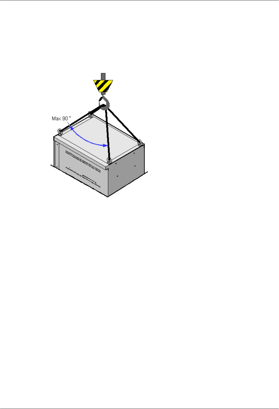
lLift the weight only when the weight lifting tools are firmly mounted onto the weight-
bearing object or the wall.
lUse a concise instruction to prevent incorrect operation.
lThe angle between the two cables should be less than or equal to 90o in the lifting of weights
(SeeFigure 1-2).
Figure 1-2 Lifting a weight
Safety Guide on Ladder Use
Checking the Ladder
lCheck the ladder before using it. Check the maximum weight that the ladder can support.
lNever overload the ladder.
Placing the Ladder
lThe slant angle is preferred to be 75o. The slant can be measured with the angle square or
with arms, as shown inFigure 1-3.When using a ladder, place the wider end of the ladder
on the ground and take protective measures on the base of the ladder against slippage. Place
the ladder on a stable ground.
When climbing the ladder, ensure the following:
lThe gravity of the body does not shift from the edge of the ladder.
lKeep balance on the ladder before performing any operation.
lDo not climb higher than the fourth highest step of the ladder.
If you tend to climb to the roof, the length of the ladder should be at least one meter higher than
the eave, as shown inFigure 1-4.
1 Safety Information
RRU3804
User Guide
1-10 Huawei Technologies Proprietary Issue 01 (2007-11-29)
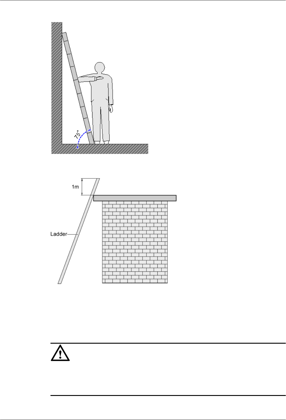
Figure 1-3 Slant angle
Figure 1-4 One meter higher than the eave
1.7 Mechanical Safety
Drilling
CAUTION
Do not drill on the cabinet without permission. Inappropriate drilling on the cabinet may
damage the electromagnetic shielding and internal cables. Metal shavings from the drilling
may result in a short-circuit of the circuit board if they get into the cabinet.
lBefore drilling a hole on the cabinet, remove the cables from the cabinet.
RRU3804
User Guide 1 Safety Information
Issue 01 (2007-11-29) Huawei Technologies Proprietary 1-11
lDuring the drilling, wear blinkers to protect your eyes.
lDuring the drilling, wear the protective gloves.
lPrevent the metal shavings from getting into the cabinet. After drilling, clean the metal
shavings in time.
Handling Sharp Objects
CAUTION
When carrying the device by hand, wear the protective gloves to prevent injury by sharp
objects.
Handling Fans
lWhen replacing a component, place the component, screw, and tool at a safe place to prevent
them from falling into the running fan.
lWhen replacing the ambient equipment around the fan, do not place the finger or board
into the running fan until the fan is switched off and stops running.
Moving Heavy Objects
Wear the protective gloves when moving heavy objects.
CAUTION
lBe careful when moving heavy objects.
lWhen moving the chassis outwards, be aware about the unfixed or heavy objects on the
chassis to prevent injury.
lTwo persons should be available to move a chassis; one person must not move a heavy
chassis. When moving a chassis, keep your back straight and move stably to prevent a
sprain.
lWhen moving or lifting a chassis, hold the handle or bottom of the chassis. Do not hold the
handle of the installed modules in the chassis, such as the power module, fan module, or
board.
1 Safety Information
RRU3804
User Guide
1-12 Huawei Technologies Proprietary Issue 01 (2007-11-29)
1.8 Others
Inserting and Removing a Board
CAUTION
When inserting a board, wear the ESD wrist strap or gloves. Insert the board gently to prevent
any bent pins on the backplane.
lInsert the board along the guide rail.
lAvoid contact of one board with another to prevent short-circuit or damage.
lDo not remove the active board before powering off.
lWhen holding a board in hand, do not touch the board circuit, components, connectors, or
connection slots.
Bundling Signal Cables
CAUTION
Bundle the signal cables separately from the strong current cables or high voltage cables.
Cabling Requirements
At a very low temperature, movement of the cable may damage the plastic skin of the cable. To
ensure the construction safety, comply with the following requirements:
lWhen installing cables, ensure that the environment temperature is above 0oC.
lIf cables are stored in the place below 0oC, move the cables into a place at a room
temperature and store the cables for more than 24 hours before installation.
lMove the cables with care, especially at a low temperature. Do not drop the cables directly
from the vehicle.
RRU3804
User Guide 1 Safety Information
Issue 01 (2007-11-29) Huawei Technologies Proprietary 1-13

2 RRU3804 and SRXU Hardware
About This Chapter
This describes the RRU3804 equipment, SRXU equipment, and related cables.
2.1 RRU3804 Equipment
The RRU3804 is an outdoor remote radio unit. The RRU3804 that is connected to the SRXU
supports 4-way RX diversity.
2.2 SRXU Equipment
The SRXU is an extended RF interface module that provides two RX channels for RF signals.
2.3 RRU3804 Cables
The RRU3804 cables include the PGND cable, power cable, AISG multi-wire cable, AISG
extension cable, CPRI optical cable, RF jumper, and Boolean input cable.
2.4 SRXU Cables
The SRXU cables include the PGND cable, power cable, AISG multi-wire cable, AISG
extension cable, CPRI optical cable, and RF jumper.
RRU3804
User Guide 2 RRU3804 and SRXU Hardware
Issue 01 (2007-11-29) Huawei Technologies Proprietary 2-1
2.1 RRU3804 Equipment
The RRU3804 is an outdoor remote radio unit. The RRU3804 that is connected to the SRXU
supports 4-way RX diversity.
The RRU3804 has the following functions:
lThe RRU3804 receives RF signals from the antenna system, down-converts the signals to
IF signals, and then transmits them to the BBU or the macro NodeB after amplification,
analog-to-digital conversion, digital down-conversion, matched filtering, and Digital
Automatic Gain Control (DAGC).
lThe RRU3804 receives downlink baseband signals from the BBU or the macro NodeB,
forwards data from its cascaded RRU3804, performs filtering and digital-to-analog
conversion, and up-converts RF signals to the transmitting frequency band.
lThe RRU3804 multiplexes RX and TX signals over RF channels and filters the RX signals
and TX signals. This enables the RX signals and TX signals to share the same antenna path.
2.1.1 DBS3800 Product Family
This describes the function modules and auxiliary facilities in the DBS3800 product family.
2.1.2 Appearance of the RRU3804
The RRU3804 features a modular structure with its ports at the module bottom and on the cabling
cavity.
2.1.3 LEDs on the RRU3804
The LEDs, on the LED panel of the RRU3804, indicate the running status of the RRU3804.
2.1.4 Ports on the RRU3804
The ports on the RRU3804 consist of grounding ports, power supply ports, transmission ports,
alarm ports, and other ports.
2.1.5 Panels of the RRU3804
The RRU3804 has a bottom panel, a cabling cavity panel, and an LED panel.
2.1.6 Engineering Specifications of the RRU3804
This describes the engineering specifications for the RRU3804.
2.1.1 DBS3800 Product Family
This describes the function modules and auxiliary facilities in the DBS3800 product family.
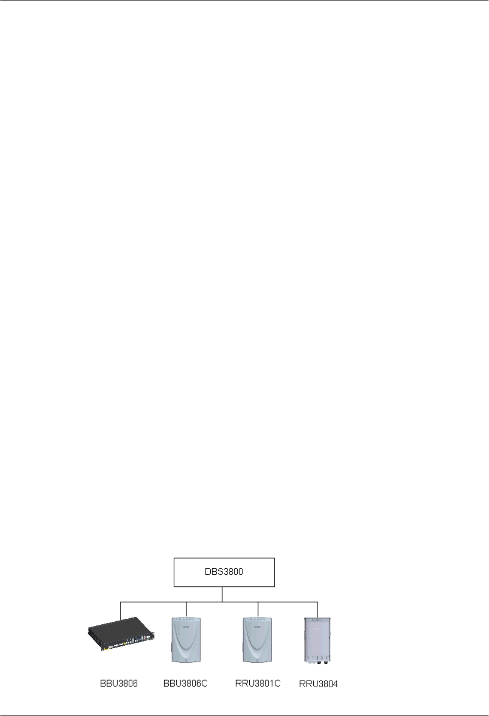
Function Modules of the DBS3800
The BBU3806, BBU3806C, RRU3801C, and RRU3804 are referred to as the function modules
of the DBS3800.
Figure 2-1 Function modules of the DBS3800
2 RRU3804 and SRXU Hardware
RRU3804
User Guide
2-2 Huawei Technologies Proprietary Issue 01 (2007-11-29)
Function
Module
Description
BBU3806 Indoor baseband unit that processes baseband signals
BBU3806C Outdoor baseband unit that processes baseband signals
RRU3801C Outdoor remote radio unit. It receives and transmits RF signals and then
transmits the processed signals to the BBU3806 or BBU3806C.
RRU3804 Outdoor remote radio unit. The RRU3804 that is connected to the SRXU
supports 4-way RX diversity.
The BBU3806, BBU3806C, and RRU3801C can be combined into a BTS3803 or BTS3803C.
lBTS3803: consists of one BBU3806, one RRU3801C, and the power system, which
processes RF and baseband signals and applies to indoor environment.
lBTS3803C: consists of one BBU3806C and one to three RRU3801Cs, which processes RF
and baseband signals and applies to outdoor environment.
Auxiliary Facilities of the DBS3800
Auxiliary
Facility
Description
APM30 Auxiliary power backup system for outdoor application. The APM30
provides the following functions:
l–48 V DC power output
lTemperature control
l2 U or 7 U space for your devices, depending on the configuration of
batteries
For details on the functions of the APM30, refer to the APM30 User
Guide.
APM100 Auxiliary power backup system for outdoor application. The APM100
provides the following functions:
l–48 V DC power output
lA maximum of 60 A output
l4 U space for your devices
For details on the functions of the APM100, refer to the APM100 User
Guide.
RRU3804
User Guide 2 RRU3804 and SRXU Hardware
Issue 01 (2007-11-29) Huawei Technologies Proprietary 2-3

Auxiliary
Facility
Description
AFB Auxiliary facility box for outdoor application. The AFB provides the
following functions:
lFour AC power outputs and four DC power outputs
lAC surge protection
lTemperature control
lAlarm reporting
l5 U space for your devices
For details on the functions of the AFB, refer to the AFB User Guide.
OFB Outdoor facility box for DC power distribution and transmission. The
OFB provides the following functions:
l11 U space for your devices
lHeat dissipation
lAlarm reporting
For details on the functions of the OFB, refer to the OFB User Guide.
SPD40R Outdoor AC surge protection device. The SPD40R provides the
following functions:
lAC surge protection
lFour AC power inputs
lRemote fault alarm reporting
lLocal fault alarm reporting
For details on the functions of the SPD40R, refer to the SPD40R User
Guide.
DPD32-1-6 Indoor facility for DC power distribution. The DPD32-1-6 provides the
following functions:
lOne DC power input at a maximum current of 32 A
lSix DC power outputs
For details on the functions of the DPD32-1-6, refer to the DPD32-1-6
User Guide.
EMUA Environment monitoring unit. The EMUA provides the following
functions:
lEnvironment monitoring
lIntrusion monitoring
lPower distribution monitoring
For details on the functions of the EMUA, refer to the EMUA User
Guide.
2 RRU3804 and SRXU Hardware
RRU3804
User Guide
2-4 Huawei Technologies Proprietary Issue 01 (2007-11-29)
Auxiliary
Facility
Description
Surge Protection
Box for Coaxial
(SPBC)
A small box for indoor application, which provides surge protection for
the coaxial cables of the BBU3806.
For details on the functions of the SPBC, refer to SPBC.
Surge Protection
Box for Twisted-
Pair (SPBT)
The surge protection unit in the SPBT is optional.
lThe SPBT without the surge protection unit works as a Digital
Distribution Frame (DDF).
lThe SPBT with the surge protection unit provides surge protection for
twisted pair cables.
For details on the functions of the SPBT, refer to SPBT.
Signal Lightning
Protection Unit
(SLPU)
The SLPU protects the E1/T1 signals and Ethernet signals over the
BBU3806 from lightning surge.
For details on the functions of the SLPU, refer to SLPU.
DDF The DDF is used for the E1/T1 cable connections between the BBU3806
and the transmission device. According to installation positions, the DDF
falls into two types, namely external DDF and built-in DDF.
For details on the functions of the DDF, refer to Built-in DDF.
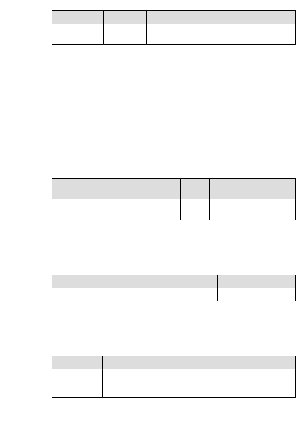
2.1.2 Appearance of the RRU3804
The RRU3804 features a modular structure with its ports at the module bottom and on the cabling
cavity.
Figure 2-2 shows the RRU3804. On the left is a front view of the RRU3804 without the housing,
in the middle is a side view of the RRU3804 without the housing, and on the right is a front view
of the RRU3804 housing.
Figure 2-2 RRU3804
RRU3804
User Guide 2 RRU3804 and SRXU Hardware
Issue 01 (2007-11-29) Huawei Technologies Proprietary 2-5

2.1.3 LEDs on the RRU3804
The LEDs, on the LED panel of the RRU3804, indicate the running status of the RRU3804.
For the positions of the LEDs on the RRU3804, refer to 2.1.5 Panels of the RRU3804.
Table 2-1 describes the LEDs and their status.
Table 2-1 LEDs on the RRU3804
Label Color Status Description
RUN Green ON The module has power input,
yet the module is faulty.
OFF The module has no power input
or is reporting alarms.
1s ON, 1s OFF The module is operational.
0.5s ON, 0.5s OFF Software is being loaded to the
module.
ALM Red ON The module is reporting alarms
(excluding VSWR-related
alarms).
OFF The module is operational.
TX_ACT Green ON The module is running.
OFF No specific meaning
VSWR Red ON VSWR-related alarms are
reported.
OFF No VSWR-related alarm is
reported.
CPRI_W Red/green ON (green) The CPRI link is normal.
ON (red) The optical module receives
local alarms related to LOS.
0.5s ON, 0.5s OFF
(red)
The CPRI link is out of lock.
OFF The optical module is not in
position or is powered off.
CPRI_E Red/green ON (green) The CPRI link is normal.
ON (red) The optical module receives
local alarms related to LOS.
0.5s ON, 0.5s OFF
(red)
The CPRI link is out of lock.
2 RRU3804 and SRXU Hardware
RRU3804
User Guide
2-6 Huawei Technologies Proprietary Issue 01 (2007-11-29)
Label Color Status Description
OFF The optical module is not in
position or is powered off.
2.1.4 Ports on the RRU3804
The ports on the RRU3804 consist of grounding ports, power supply ports, transmission ports,
alarm ports, and other ports.
Grounding Ports
The RRU3804 has four grounding bolts at the bottom.
Power Supply Ports
Table 2-2 Power supply port on the RRU3804
Application Port Quanti
ty
Connector Type
Power supply –48 V DC power
supply
1 OT terminal
Transmission Ports
Table 2-3 Transmission ports on the RRU3804
Port Quantity Data Rate Connector Type
Optical ports 2 1.25 Gbit/s ESFP socket
Alarms Ports
Table 2-4 Alarm port on the RRU3804
Application Port Quantity Connector Type
Alarms 2-channel dry contact
alarms, 1-channel
RS485 signals
1 DB15
RRU3804
User Guide 2 RRU3804 and SRXU Hardware
Issue 01 (2007-11-29) Huawei Technologies Proprietary 2-7
Table 2-5 Specifications for the alarm port on the RRU3804
Item Specification
Closed resistance < 0.2 kilohms
Open resistance > 51 kilohms
Other Ports
Table 2-6 Other ports on the RRU3804
Application Port Quanti
ty
Connector Type
RET antenna/power
input to the SRXU
- 1 DB9, waterproof
RF Main TX/RX 1 DIN, round, and waterproof
RX diversity 1 DIN, round, and waterproof
Interconnection
between combined
cabinets
1 2W2
2.1.5 Panels of the RRU3804
The RRU3804 has a bottom panel, a cabling cavity panel, and an LED panel.
Figure 2-3 shows the panels of the RRU3804.
2 RRU3804 and SRXU Hardware
RRU3804
User Guide
2-8 Huawei Technologies Proprietary Issue 01 (2007-11-29)
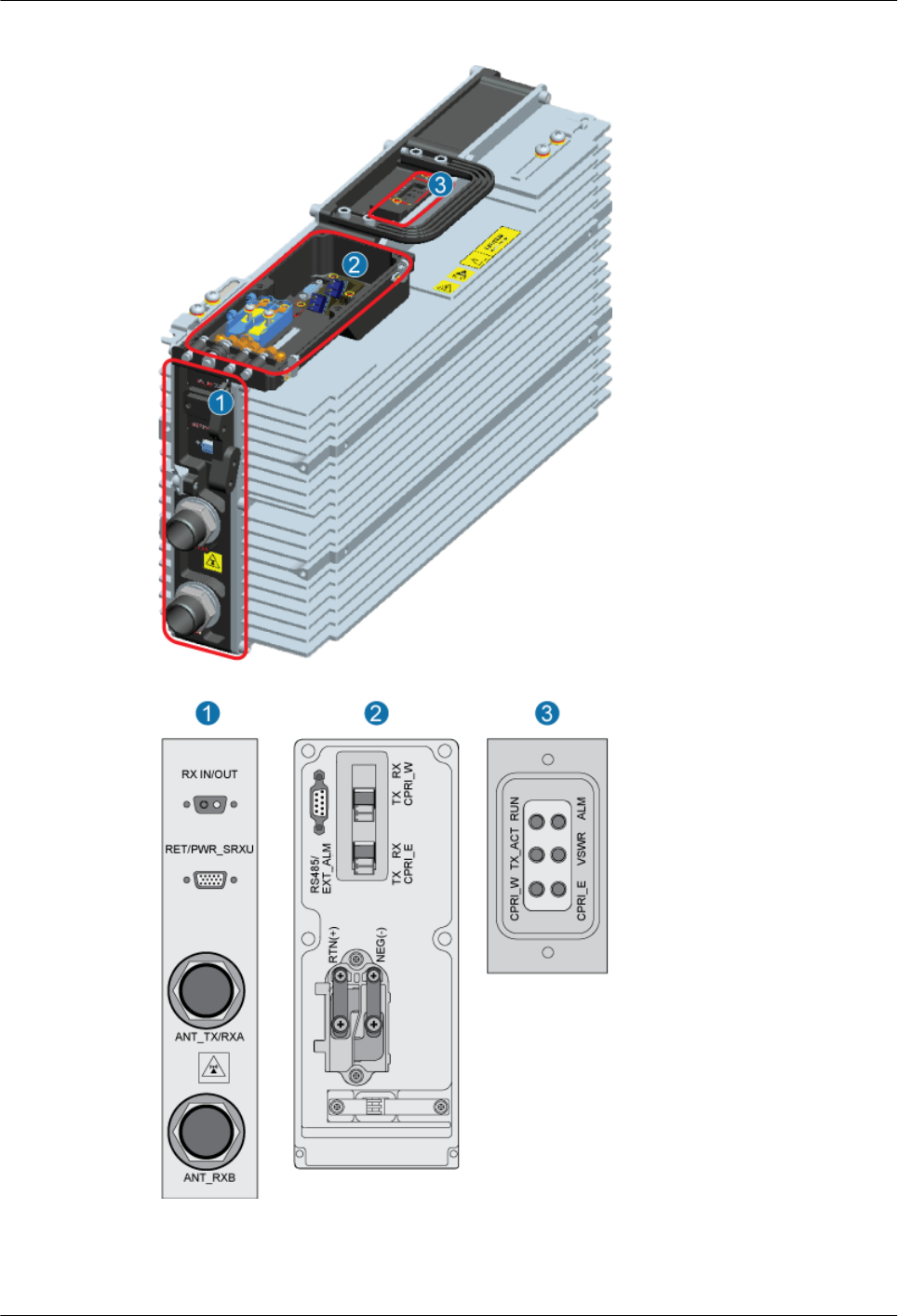
Figure 2-3 Panels of the RRU3804
Table 2-7 describes the ports and LEDs on the panels of the RRU3804.
RRU3804
User Guide 2 RRU3804 and SRXU Hardware
Issue 01 (2007-11-29) Huawei Technologies Proprietary 2-9

Table 2-7 Ports and LEDs on the panels of the RRU3804
Item Label Description
Ports at the
bottom
RX_IN/OUT Port for interconnection between combined
cabinets
RET/PWR_SRXU Port for the RET antenna or power output to
the SRXU
ANT_TX/RXA Port for main TX/RX diversity
ANT_RXB Port for diversity reception
Ports on the
cabling cavity
RS485/EXT_ALM Port for alarms
CPRI_E Optical ports
CPRI_W
RTN(+) Ports for power supply
NEG(-)
PGND Grounding bolt
LEDs RUN For details, refer to 2.1.3 LEDs on the
RRU3804.
ALM
TX_ACT
VSWR
CPRI_W
CPRI_E
2.1.6 Engineering Specifications of the RRU3804
This describes the engineering specifications for the RRU3804.
Dimensions
The dimensions of the RRU3804 (including the mounting plate and housing) are 280 mm x 155
mm x 488 mm (W x D x H).
Weight
The weight of the RRU3804 is 17 kg at most.
2 RRU3804 and SRXU Hardware
RRU3804
User Guide
2-10 Huawei Technologies Proprietary Issue 01 (2007-11-29)

Power Input
Table 2-8 Power input to the RRU3804
Rated Voltage Operating Voltage
Range
Remarks
–48 V DC –37 V DC to –60 V DC -
Power Consumption
The maximum power consumption of the RRU3804 is 280 W.
2.2 SRXU Equipment
The SRXU is an extended RF interface module that provides two RX channels for RF signals.
The SRXU receives RF signals from the antenna system, down-converts the signals to IF signals,
and then transmits them to the RRU3804 after amplification, analog-to-digital conversion,
digital down-conversion, matched filtering, and DAGC. The RRU3804 forwards the signals to
the BBU or the macro NodeB.
2.2.1 Appearance of the SRXU
The SRXU features a modular structure with its ports at the module bottom and on the cabling
cavity.
2.2.2 LEDs on the SRXU
The LEDs, on the LED panel of the SRXU, indicate the running status of the SRXU.
2.2.3 Ports on the SRXU
The ports on the SRXU consist of grounding ports, power supply ports, transmission ports, and
other ports.
2.2.4 Panels of the SRXU
The SRXU has a bottom panel, a cabling cavity panel, and an LED panel.
2.2.5 Engineering Specifications of the SRXU
This describes the engineering specifications of the SRXU.
2.2.1 Appearance of the SRXU
The SRXU features a modular structure with its ports at the module bottom and on the cabling
cavity.
Figure 2-4 shows the SRXU. On the left is a front view of the SRXU, and on the right is a side
view of the SRXU.
RRU3804
User Guide 2 RRU3804 and SRXU Hardware
Issue 01 (2007-11-29) Huawei Technologies Proprietary 2-11
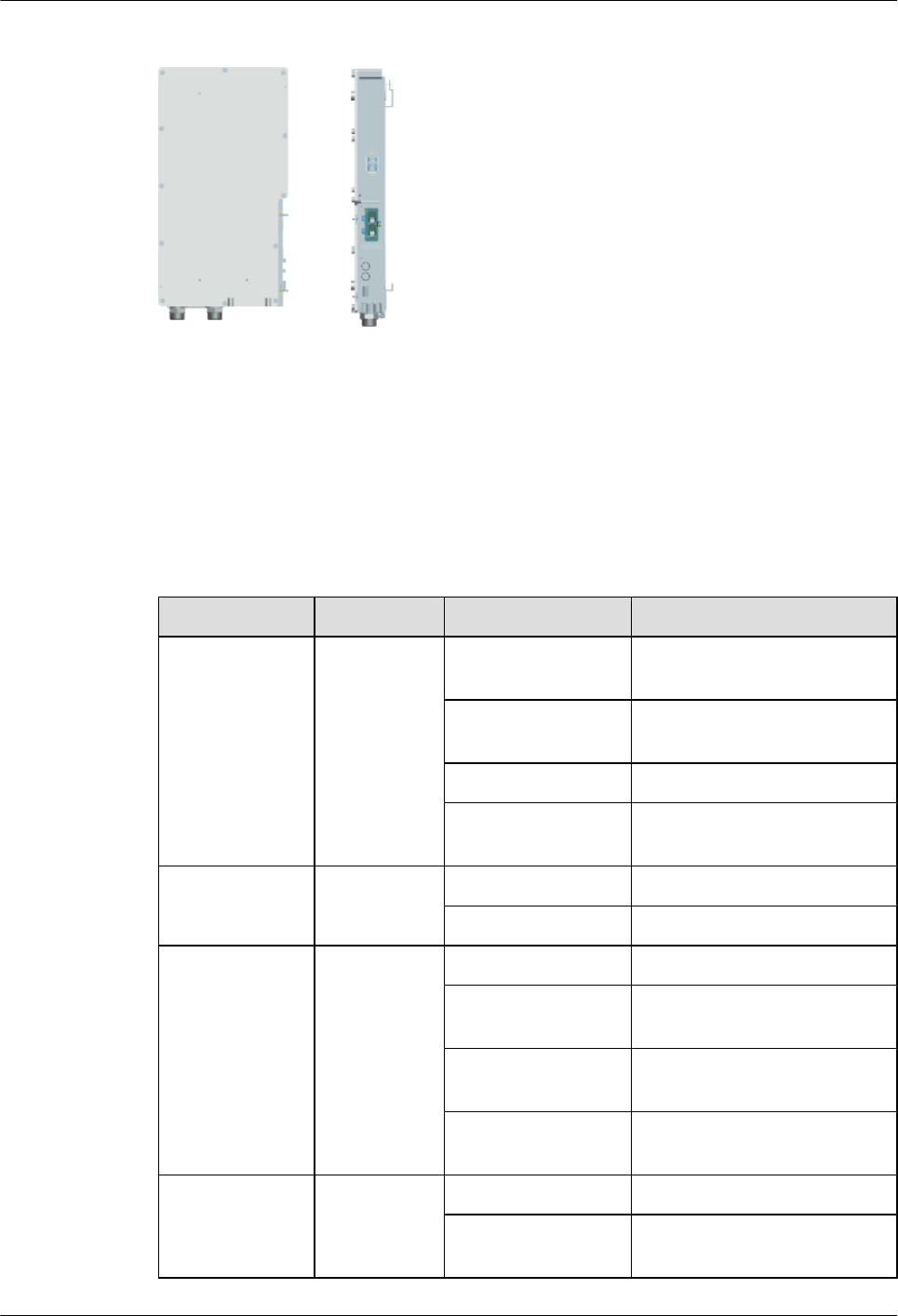
Figure 2-4 SRXU
2.2.2 LEDs on the SRXU
The LEDs, on the LED panel of the SRXU, indicate the running status of the SRXU.
For the positions of the LEDs on the SRXU, refer to 2.2.4 Panels of the SRXU.
Table 2-9 describes the LEDs and their status.
Table 2-9 LEDs on the SRXU
Label Color Status Description
RUN Green ON The module has power input,
yet the module is faulty.
OFF The module has no power input,
or the module is faulty.
1s ON, 1s OFF The module is operational.
0.5s ON, 0.5s OFF Software is being loaded to the
module.
ALM Red ON The module is reporting alarms.
OFF The module is operational.
CPRI_W Red/green ON (green) The CPRI link is normal.
ON (red) The optical module receives
local alarms related to LOS.
0.5s ON, 0.5s OFF
(red)
The CPRI link is out of lock.
OFF The optical module is not in
position or is powered off.
CPRI_E Red/green ON (green) The CPRI link is normal.
ON (red) The optical module receives
local alarms related to LOS.
2 RRU3804 and SRXU Hardware
RRU3804
User Guide
2-12 Huawei Technologies Proprietary Issue 01 (2007-11-29)
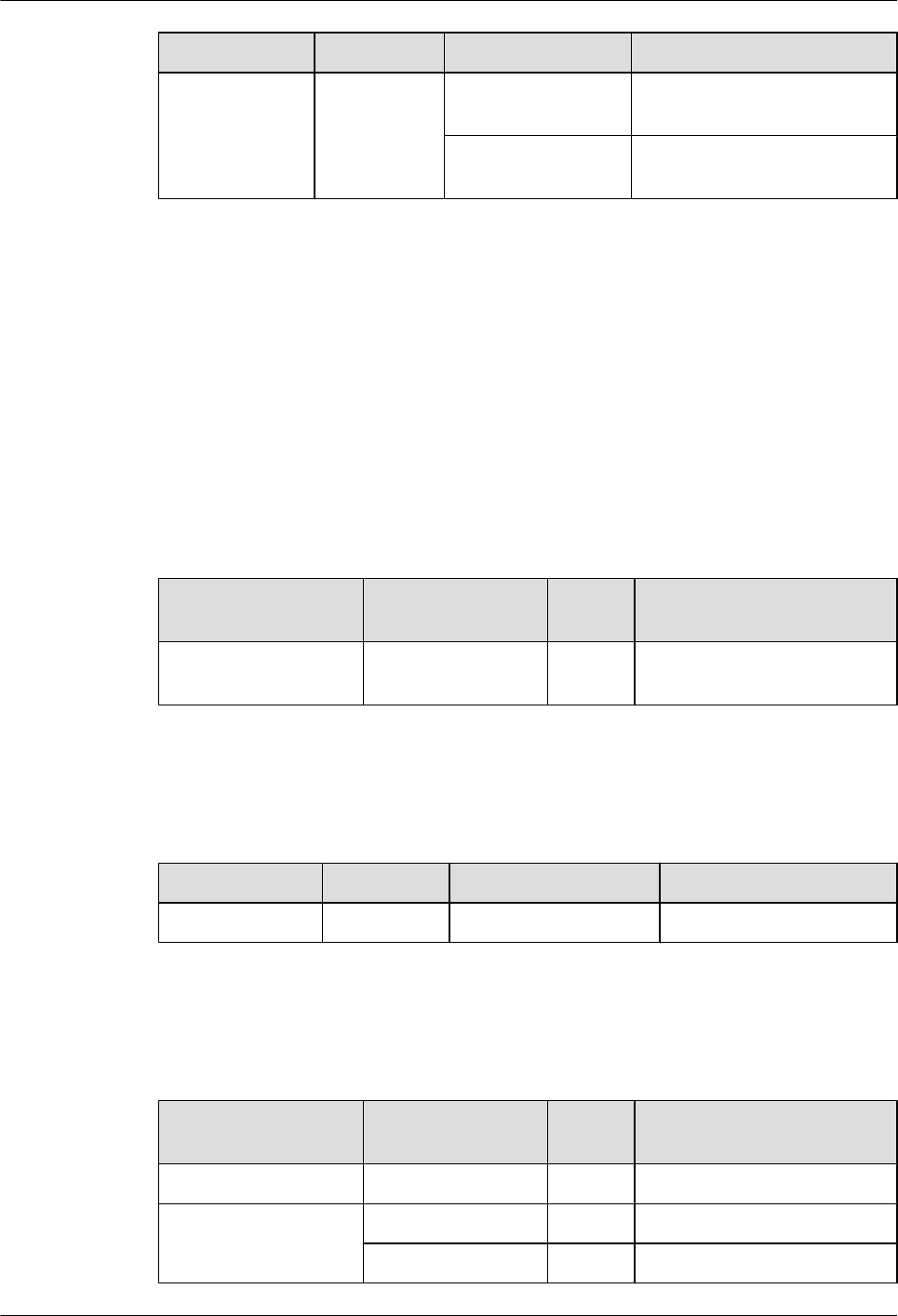
Label Color Status Description
0.5s ON, 0.5s OFF
(red)
The CPRI link is out of lock.
OFF The optical module is not in
position or is powered off.
2.2.3 Ports on the SRXU
The ports on the SRXU consist of grounding ports, power supply ports, transmission ports, and
other ports.
Grounding Ports
The SRXU has two grounding bolts at the bottom.
Power Supply Ports
Table 2-10 Power supply ports on the SRXU
Application Port Quanti
ty
Connector Type
Power supply DC power from the
RRU3804
1 DB9, waterproof
Transmission Ports
Table 2-11 Transmission ports on the SRXU
Port Quantity Data Rate Connector Type
Optical port 2 1.25 Gbit/s ESFP socket
Other Ports
Table 2-12 Other ports on the SRXU
Application Port Quanti
ty
Connector Type
RET antenna - 1 DB9, waterproof
RF Main TX/RX 1 DIN, round, and waterproof
RX diversity 1 DIN, round, and waterproof
RRU3804
User Guide 2 RRU3804 and SRXU Hardware
Issue 01 (2007-11-29) Huawei Technologies Proprietary 2-13
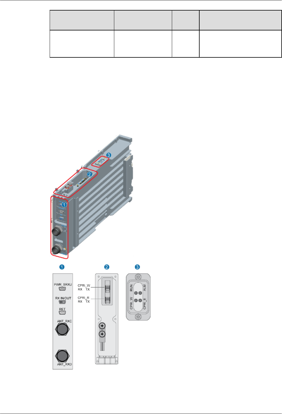
Application Port Quanti
ty
Connector Type
Interconnection
between combined
cabinets
1 2W2
2.2.4 Panels of the SRXU
The SRXU has a bottom panel, a cabling cavity panel, and an LED panel.
Figure 2-5 shows the panels of the SRXU.
Figure 2-5 Panels of the SRXU
Table 2-13 describes the ports and LEDs on the panels of the SRXU.
2 RRU3804 and SRXU Hardware
RRU3804
User Guide
2-14 Huawei Technologies Proprietary Issue 01 (2007-11-29)
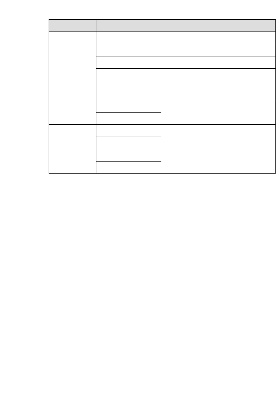
Table 2-13 Ports and LEDs on the panels of the SRXU
Item Label Description
Ports at the
bottom
PWR_SRXU Socket for power supply
ANT_RXC Port for diversity reception
ANT_RXD Port for diversity reception
RX_IN/OUT Port for interconnection between combined
cabinets
RET Port for the RET antenna
Ports on the
cabling cavity
CPRI_E Optical ports
CPRI_W
LEDs RUN For details, refer to 2.1.3 LEDs on the
RRU3804.
ALM
CPRI_W
CPRI_E
2.2.5 Engineering Specifications of the SRXU
This describes the engineering specifications of the SRXU.
Dimensions
The dimensions of the SRXU are 260 mm x 60 mm x 480 mm (W x D x H).
Weight
The weight of the SRXU is 6 kg at most.
Power Consumption
The maximum power consumption of the SRXU is 30 W.
2.3 RRU3804 Cables
The RRU3804 cables include the PGND cable, power cable, AISG multi-wire cable, AISG
extension cable, CPRI optical cable, RF jumper, and Boolean input cable.
2.3.1 PGND Cable of the RRU3804
The PGND cable ensures the grounding of the RRU3804.
2.3.2 Power Cable of the RRU3804
The RRU3804 uses a shielded –48 V DC power cable. The cable feeds external –48 V DC power
to the RRU3804.
RRU3804
User Guide 2 RRU3804 and SRXU Hardware
Issue 01 (2007-11-29) Huawei Technologies Proprietary 2-15
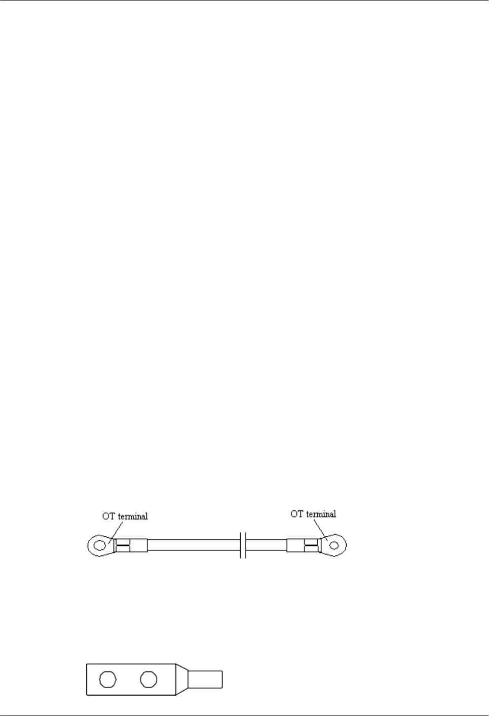
2.3.3 AISG Multi-Wire Cable of the RRU3804/SRXU
The five-meter-long AISG multi-wire cable connects the RRU3804/SRXU to the Remote
Control Unit (RCU). If both RRU3804 and SRXU are installed, the AISG multi-wire cable only
connects the SRXU and the RCU. This cable is optional.
2.3.4 AISG Extension Cable of the RRU3804/SRXU
When the distance between the RCU and the RRU3804/SRXU is longer than 5 m, the AISG
multi-wire cable is not long enough to cover the distance and the AISG extension cable is used.
The AISG extension cable is 15 m long.
2.3.5 BBU3806-RRU/SRXU CPRI Optical Cable
The CPRI optical cable transmits CPRI signals between BBU3806 and RRU3801C, between
BBU3806 and RRU3804, and between RRU3804 and SRXU.
2.3.6 BBU3806C-RRU/SRXU CPRI Optical Cable
The CPRI optical cable transmits CPRI signals between BBU3806C and RRU3801C, between
BBU3806C and RRU3804, and between RRU3804 and SRXU.
2.3.7 RF Jumper of the RRU3804/SRXU
The RF jumper of the RRU3804/SRXU is of two types: antenna jumper and interconnect jumper.
The interconnect jumper is optional, depending on the site configuration.
2.3.8 Boolean/RS485 Input Cable of the RRU3804
The cable transmits the 2-channel Boolean alarm signals and 1-channel RS485 signals from
external devices to the RRU3804. Thus, the external signals are monitored.
2.3.1 PGND Cable of the RRU3804
The PGND cable ensures the grounding of the RRU3804.
Appearance
The green and yellow PGND cable is a single cable with a cross-sectional area of 16 mm2. Both
ends of the cable are OT terminals. If you prepare the cable by yourself, it is recommended to
use a copper-based cable with a minimum cross-sectional area of 16 mm2.
Figure 2-6 shows the PGND cable.
Figure 2-6 PGND cable
Both ends of the PGND cable need to be made into OT terminals on site. You can determine the
color of the cable and whether to use 2-hole terminals according to local standards.
Figure 2-7 shows the 2-hole terminal.
Figure 2-7 2-hole terminal
2 RRU3804 and SRXU Hardware
RRU3804
User Guide
2-16 Huawei Technologies Proprietary Issue 01 (2007-11-29)
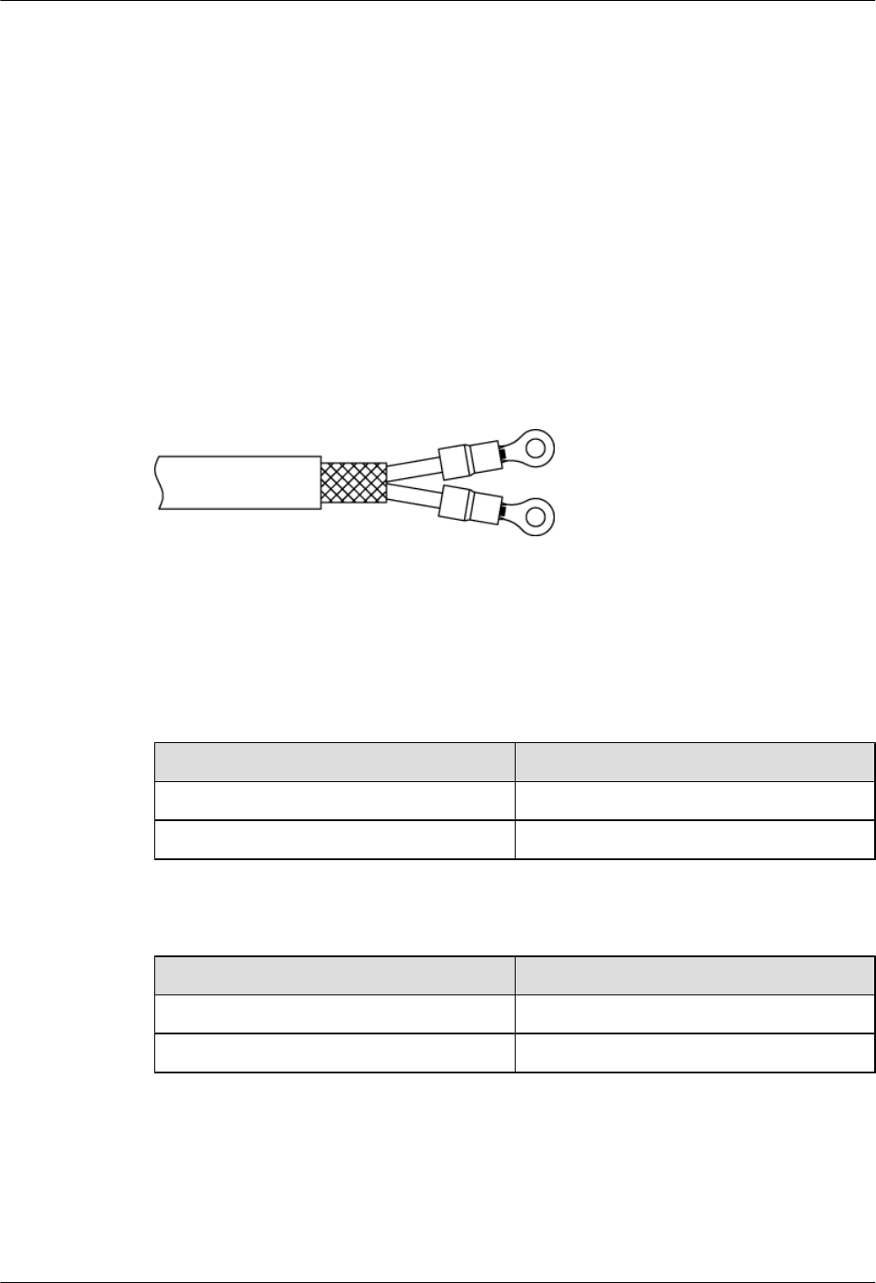
Installation Position
One end of the PGND cable is connected to the grounding bolt on the RRU3804, and the other
end is connected to the nearest grounding bar.
2.3.2 Power Cable of the RRU3804
The RRU3804 uses a shielded –48 V DC power cable. The cable feeds external –48 V DC power
to the RRU3804.
Appearance
One end of the cable is two OT terminals, and the other end is bare, as shown in Figure 2-8.
The OT terminals need to be made on site.
Figure 2-8 –48 V DC power cable
Pin Assignment
The –48 V DC cable is a 2-wire cable. Table 2-14 and Table 2-15 describe the pin assignment
for the wires of the –48 V DC power cable.
Table 2-14 Pin assignment for the wires of the –48 V DC power cable (North American
Standard)
Wire Type Wire Color
NEG Blue
RTN Black
Table 2-15 Pin assignment for the wires of the –48 V DC power cable (European Standard)
Wire Type Wire Color
NEG Blue
RTN Brown
Installation Position
At one end of the cable, the OT terminal on the blue wire is connected to the NEG(-) port on the
cabling cavity of the RRU3804, and the OT terminal on the black or brown wire is connected
to the RTN(+) port on the cabling cavity of the RRU3804.
RRU3804
User Guide 2 RRU3804 and SRXU Hardware
Issue 01 (2007-11-29) Huawei Technologies Proprietary 2-17
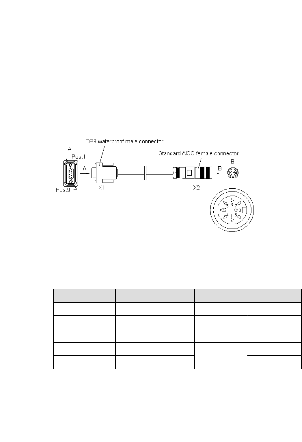
At the other end of the cable, a proper terminal is made depending on field requirements and is
then connected to the power supply on site.
2.3.3 AISG Multi-Wire Cable of the RRU3804/SRXU
The five-meter-long AISG multi-wire cable connects the RRU3804/SRXU to the Remote
Control Unit (RCU). If both RRU3804 and SRXU are installed, the AISG multi-wire cable only
connects the SRXU and the RCU. This cable is optional.
Appearance
One end of the AISG multi-wire cable is a waterproof DB9 connector, and the other end is a
standard AISG female connector, as shown in Figure 2-9.
Figure 2-9 AISG multi-wire cable
Pin Assignment
Table 2-16 describes the pin assignment for the wires of the AISG multi-wire cable.
Table 2-16 Pin assignment for the wires of the AISG multi-wire cable
X1 End X2 End Wire Type Remarks
X1.1 X2.1 Twisted pair +12 V
X1.7 X2.7 Twisted pair DC-GND
X1.9 AISG_Switch
X1.3 X2.3 Twisted pair RS485 -
X1.5 X2.5 RS485 +
Installation Position
If only the RRU3804 is installed, the waterproof DB9 connector is linked to the RET/
PWR_SRXU port at the bottom of the RRU3804, and the standard AISG female connector is
linked to the corresponding connector on the RCU or to the AISG extension cable.
2 RRU3804 and SRXU Hardware
RRU3804
User Guide
2-18 Huawei Technologies Proprietary Issue 01 (2007-11-29)
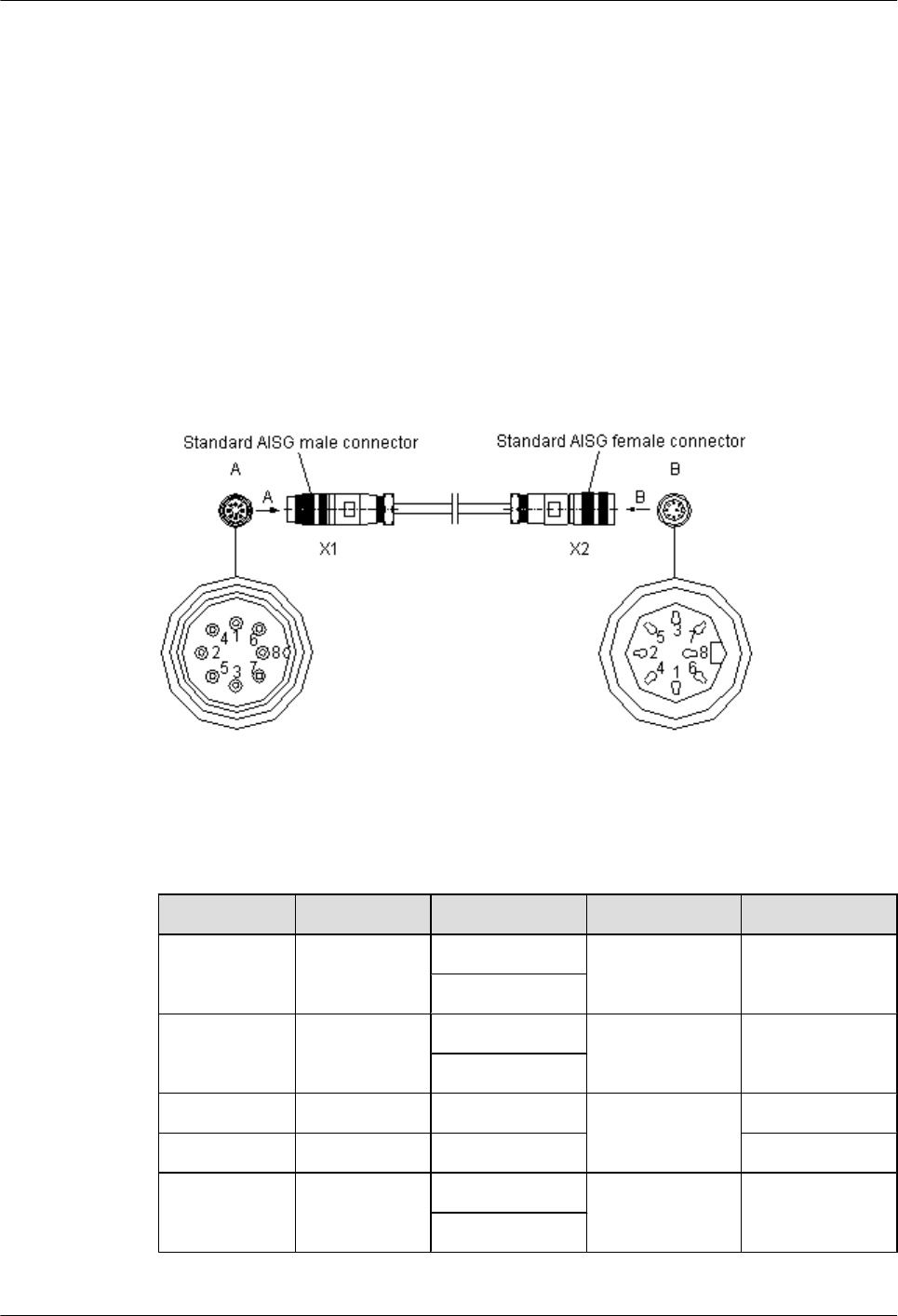
If both the RRU3804 and the SRXU are installed, the waterproof DB9 connector is linked to the
RET port at the bottom of the SRXU, and the standard AISG female connector is linked to the
corresponding connector on the RCU or to the AISG extension cable.
2.3.4 AISG Extension Cable of the RRU3804/SRXU
When the distance between the RCU and the RRU3804/SRXU is longer than 5 m, the AISG
multi-wire cable is not long enough to cover the distance and the AISG extension cable is used.
The AISG extension cable is 15 m long.
Appearance
One end of the AISG extension cable is a standard AISG male connector, and the other end is
a standard AISG female connector, as shown in Figure 2-10.
Figure 2-10 AISG extension cable
Pin Assignment
Table 2-17 describes the pin assignment for the wires of the AISG extension cable.
Table 2-17 Pin assignment for the wires of the AISG extension cable
X1 End X2 End Wire Color Wire Type Remarks
X1.1 X2.1 White/blue Twisted pair +12 V
Blue
X1.7 X2.7 White/orange Twisted pair DC Return A
Orange
X1.3 X2.3 White/green Twisted pair RS485 B
X1.5 X2.5 Green RS485 A
X1.6 X2.6 White/brown Twisted pair +24 V
Brown
RRU3804
User Guide 2 RRU3804 and SRXU Hardware
Issue 01 (2007-11-29) Huawei Technologies Proprietary 2-19
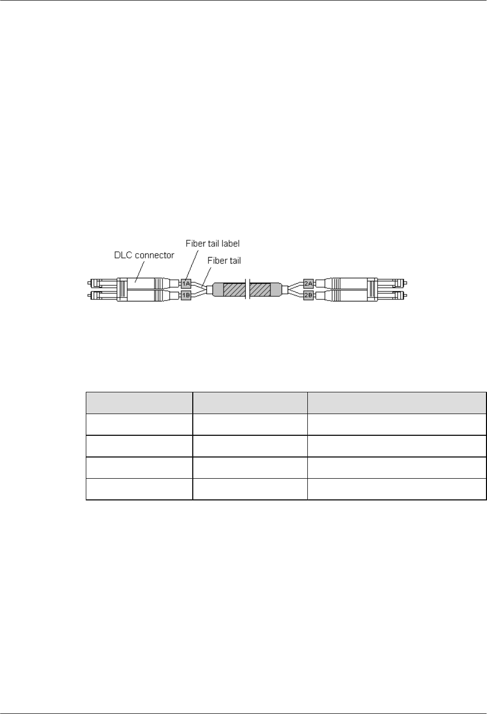
Installation Position
The AISG female connector is linked to the corresponding connector on the RCU, and the AISG
male connector is linked to the AISG female connector of the AISG multi-wire cable.
2.3.5 BBU3806-RRU/SRXU CPRI Optical Cable
The CPRI optical cable transmits CPRI signals between BBU3806 and RRU3801C, between
BBU3806 and RRU3804, and between RRU3804 and SRXU.
Appearance
The CPRI optical cable is a multi-mode 2-wire cable with DLC connectors at both ends.
Figure 2-11 shows the CPRI optical cable.
Figure 2-11 CPRI optical cable
Pin Assignment
Table 2-18 describes the pin assignment for the fiber tails.
Table 2-18 Pin assignment for the fiber tails
Label Color Connect to...
1A Orange RX port on the RRU
1B Gray TX port on the RRU
2A Orange TX port on the BBU3806
2B Gray RX port on the BBU3806
Connections of BBU3806-RRU CRPI Optical Cable in Typical Configurations
The connections of the CPRI optical cable between the BBU3806 and the RRU depend on
specific networking modes.
Figure 2-12 and Figure 2-13 show the connections of the optical cable between the BBU3806
and the RRU in two typical configurations.
2 RRU3804 and SRXU Hardware
RRU3804
User Guide
2-20 Huawei Technologies Proprietary Issue 01 (2007-11-29)
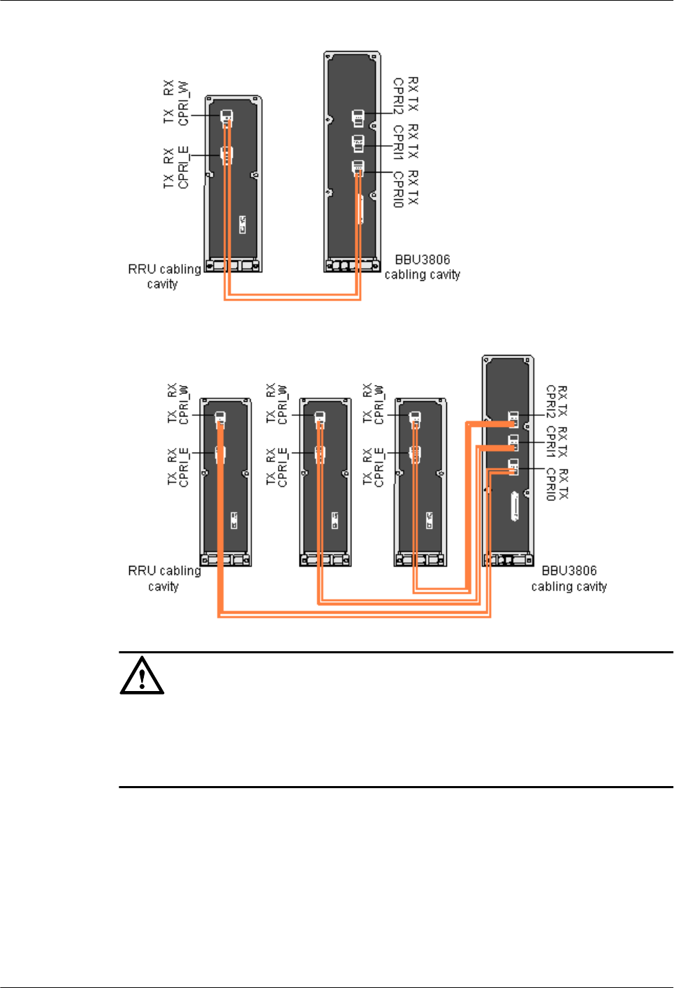
Figure 2-12 Connecting the CPRI optical cable in 1 x 1 configuration (no TX diversity)
Figure 2-13 Connecting the CPRI optical cable in 3 x 1 configuration (no TX diversity)
CAUTION
To connect the optical cable, adhere to the following rules:
lThe TX port on the BBU3806 is connected to the RX port on the RRU.
lThe RX port on the BBU3806 is connected to the TX port on the RRU.
2.3.6 BBU3806C-RRU/SRXU CPRI Optical Cable
The CPRI optical cable transmits CPRI signals between BBU3806C and RRU3801C, between
BBU3806C and RRU3804, and between RRU3804 and SRXU.
Appearance
The CPRI optical cable is a multi-mode 2-wire cable with LC connectors at both ends. Figure
2-14 shows the CPRI optical cable.
RRU3804
User Guide 2 RRU3804 and SRXU Hardware
Issue 01 (2007-11-29) Huawei Technologies Proprietary 2-21
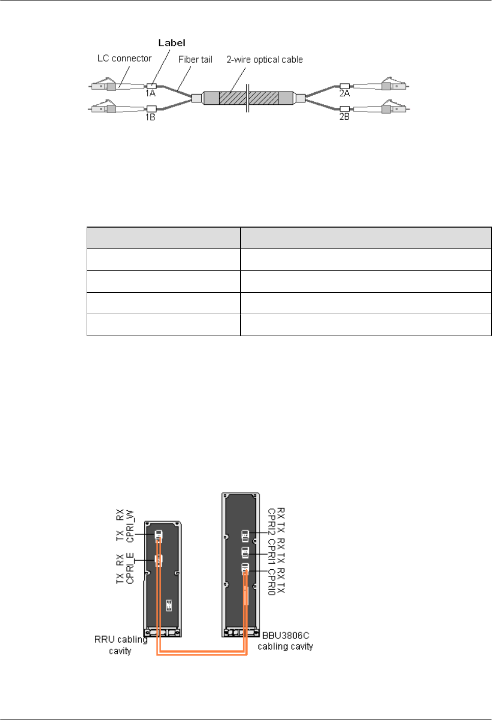
Figure 2-14 CPRI optical cable
Pin Assignment
Table 2-19 describes the pin assignment for the fiber tails of the CRPI optical cable. These
connections are recommended.
Table 2-19 Pin assignment for the fiber tails of the CRPI optical cable
Label Connect to...
1A TX port on the BBU3806C
1B RX port on the BBU3806C
2A RX port on the RRU or SRXU
2B TX port on the RRU or SRXU
Connections of BBU3806C-RRU CRPI Optical Cable in Typical Configurations
The connections of the CPRI optical cable between the BBU3806C and the RRU depend on
specific networking modes.
Figure 2-15 and Figure 2-16 show the connections of the optical cable between the BBU3806C
and the RRU in two typical configurations.
Figure 2-15 Connecting the CPRI optical cable in 1 x 1 configuration (no TX diversity)
2 RRU3804 and SRXU Hardware
RRU3804
User Guide
2-22 Huawei Technologies Proprietary Issue 01 (2007-11-29)
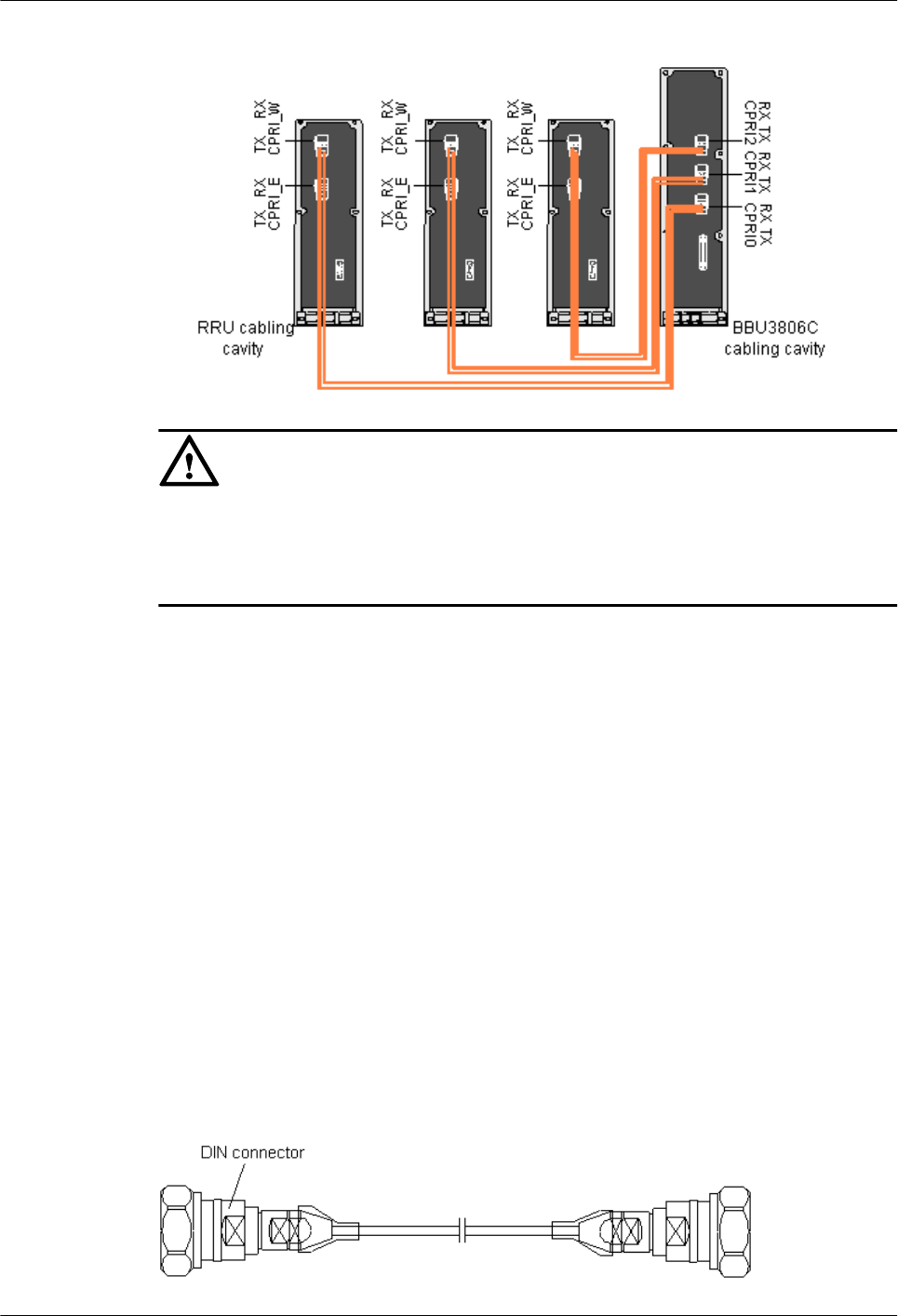
Figure 2-16 Connecting the CPRI optical cable in 3 x 1 configuration (no TX diversity)
CAUTION
To connect the optical cable, adhere to the following rules:
lThe TX port on the BBU3806C is connected to the RX port on the RRU.
lThe RX port on the BBU3806C is connected to the TX port on the RRU.
2.3.7 RF Jumper of the RRU3804/SRXU
The RF jumper of the RRU3804/SRXU is of two types: antenna jumper and interconnect jumper.
The interconnect jumper is optional, depending on the site configuration.
2.3.7.1 Antenna Jumper of the RRU3804/SRXU
The antenna jumper transmits and receives RF signals.
2.3.7.2 Interconnect Jumper of the RRU3804/SRXU
The interconnect jumper transmits RF signals between two RRU3804s/SRXUs.
2.3.7.3 RF Cable Connections of the RRU3804
One end of the RF jumper is connected to the RF ports on the RRU3804 and the other end to
the feeder. Which RF port to use depends on the networking modes.
Antenna Jumper of the RRU3804/SRXU
The antenna jumper transmits and receives RF signals.
Appearance
Both ends of the antenna jumper have DIN connectors, as shown in Figure 2-17.
Figure 2-17 Antenna jumper
RRU3804
User Guide 2 RRU3804 and SRXU Hardware
Issue 01 (2007-11-29) Huawei Technologies Proprietary 2-23
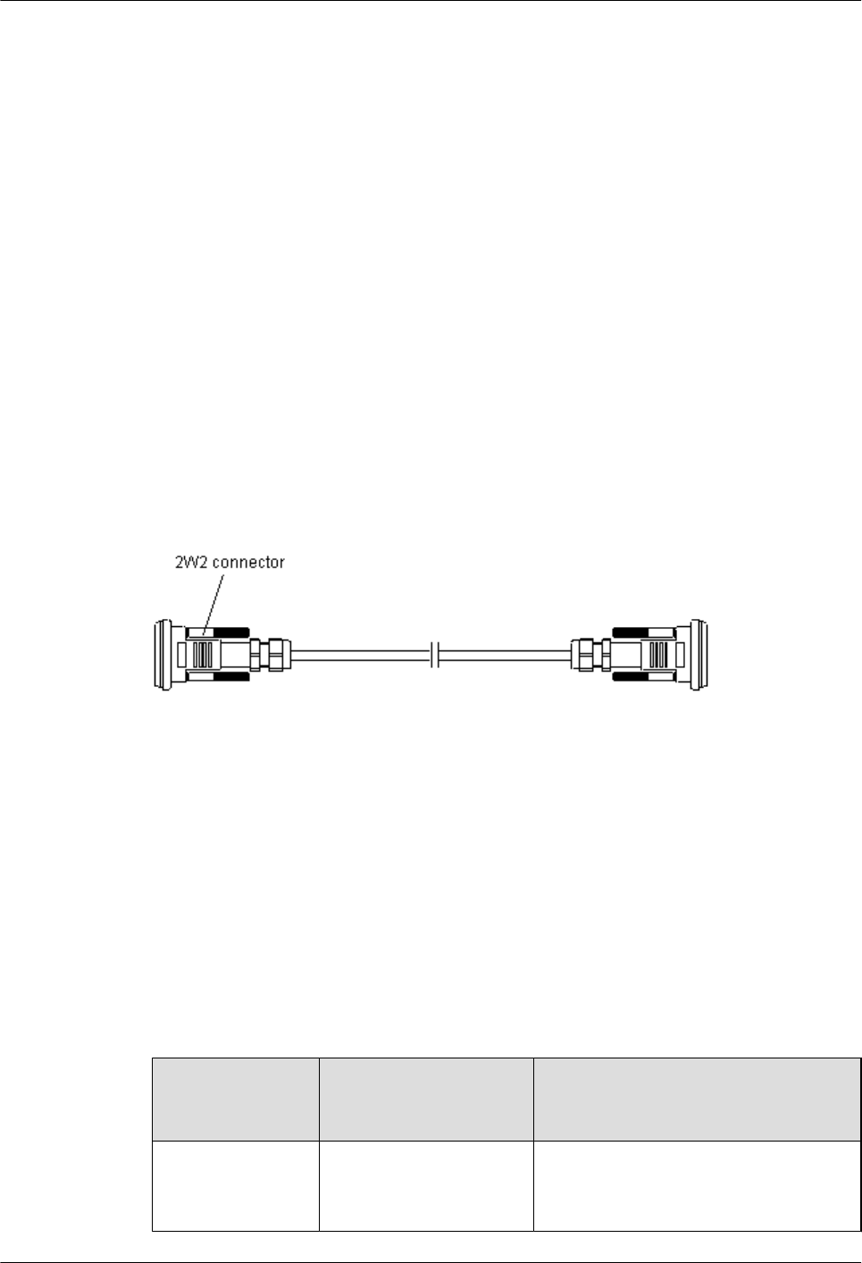
Installation Position
The antenna jumper with indefinite length is selected according to the distance between the
antenna and the RRU3804/SRXU. Connectors are made on site.
lWhen the distance between the antenna and the RRU3804/SRXU is shorter than 14 m, the
RRU3804/SRXU is directly connected to the antenna through the antenna jumper.
lWhen the distance between the antenna and the RRU3804/SRXU is longer than 14 m, the
antenna jumper should be shorter than 2 m. If you prepare the jumper by yourself, it is
recommended that the antenna jumper be 2 m long at most. Ensure that the antenna jumper
is connected to the feeder before being connected to the RRU3804/SRXU and the antenna.
Interconnect Jumper of the RRU3804/SRXU
The interconnect jumper transmits RF signals between two RRU3804s/SRXUs.
Appearance
The interconnect jumper is 2 m long, and both ends have 2W2 connectors, as shown in Figure
2-18.
Figure 2-18 Interconnect jumper
Installation Position
The 2W2 connectors at the two ends of the interconnect jumper are linked to the ports labeled
RX_IN/OUT on two RRU3804s/SRXUs respectively.
RF Cable Connections of the RRU3804
One end of the RF jumper is connected to the RF ports on the RRU3804 and the other end to
the feeder. Which RF port to use depends on the networking modes.
Table 2-20 describes the connections of the RF jumpers in different RRU3804 networking
modes.
Table 2-20 RF jumper connections of the RRU3804
Typical
Networking
Mode
Antenna Type and
Quantity of RRU3804s
Cable Connection
1 x 1 in no TX
diversity mode
lOne RRU3804
lOne dual polarization
antenna
lTwo antenna jumpers
lThe DIN connectors of the two antenna
jumpers are linked to the ANT_TX/
2 RRU3804 and SRXU Hardware
RRU3804
User Guide
2-24 Huawei Technologies Proprietary Issue 01 (2007-11-29)

Typical
Networking
Mode
Antenna Type and
Quantity of RRU3804s
Cable Connection
1 x 2 in no TX
diversity mode
RXA and ANT_RXB ports at the
bottom of the RRU3804.
2 x 1 in no TX
diversity mode
lTwo RRU3804s
lTwo dual polarization
antennas
lFour antenna jumpers
lThe DIN connectors of the four
antenna jumpers are linked to the
ANT_TX/RXA ports and ANT_RXB
ports on RRU3804 0 and RRU3804 1.
2 x 2 in no TX
diversity mode
1 x 1 in TX diversity
mode
lTwo RRU3804s
lOne dual polarization
antenna
lTwo antenna jumpers and one
interconnect jumper
lThe DIN connectors of the two antenna
jumpers are linked to the ANT_TX/
RXA ports on RRU3804 0 and
RRU3804 1.
lThe interconnect jumper is connected
to the RX_IN/OUT ports on RRU3804
0 and RRU3804 1 that are combined.
1 x 2 in TX diversity
mode
3 x 1 in no TX
diversity mode
lThree RRU3804s
lThree dual polarization
antennas
lSix antenna jumpers
lThe DIN connectors of the six antenna
jumpers are linked to the ANT_TX/
RXA ports and ANT_RXB ports on
RRU3804 0, RRU3804 1, and
RRU3804 2.
3 x 2 in no TX
diversity mode
4-way RX diversity lOne RRU3804
lOne SRXU
lTwo antenna jumpers and one DC
power cable
lThe DIN connectors of the two antenna
jumpers are linked to the ANT_RXC
and ANT_RXD ports at the bottom of
the SRXU.
lOne end of the DC power cable is
connected to the RET/PWR_SRXU
port at the bottom of the RRU3804, and
the other end is connected to the
PWR_SRXU socket at the bottom of
the SRXU.
2.3.8 Boolean/RS485 Input Cable of the RRU3804
The cable transmits the 2-channel Boolean alarm signals and 1-channel RS485 signals from
external devices to the RRU3804. Thus, the external signals are monitored.
RRU3804
User Guide 2 RRU3804 and SRXU Hardware
Issue 01 (2007-11-29) Huawei Technologies Proprietary 2-25
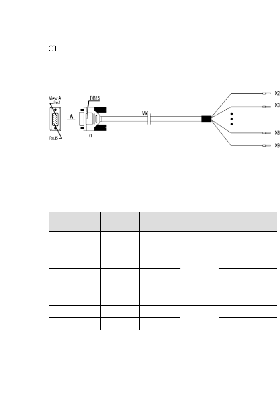
Appearance
One end of the cable has a DB15 female connector, and the other end has eight cord end terminals,
as shown in Figure 2-19.
NOTE
If the cord end terminals of the cable do no match the ports on the external devices, cut off the cord end
terminals and make proper terminals on site.
Figure 2-19 Boolean/RS485 input cable
Pin Assignment
The cable can transmit 2-channel Boolean alarm signals and 1-channel RS485 signals. Table
2-21 describes the pin assignment for the wires of the Boolean/RS485 input cable.
Table 2-21 Pin assignment for the wires of the Boolean/RS485 input cable
X1 End Cord End
Terminal
Wire Color Wire Type Label
X1.2 X2 White/blue Twisted pair SWITCH_INPUT0+
X1.3 X3 Blue GND
X1.6 X4 White/orange Twisted pair SWITCH_INPUT1+
X1.7 X5 Orange GND
X1.10 X6 White/green Twisted pair RS485_TX-
X1.11 X7 Green RS485_TX+
X1.13 X8 White/brown Twisted pair RS485_RX-
X1.14 X9 Brown RS485_RX+
Installation Position
The DB15 male connector is linked to the RS485/EXT_ALM port on the cabling cavity of the
RRU3804, and the other end of the cable is connected to the ports for Boolean alarm signals on
the external device.
2 RRU3804 and SRXU Hardware
RRU3804
User Guide
2-26 Huawei Technologies Proprietary Issue 01 (2007-11-29)
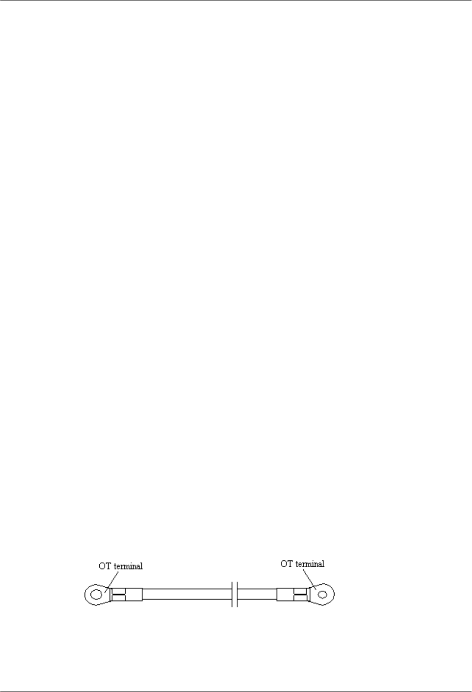
2.4 SRXU Cables
The SRXU cables include the PGND cable, power cable, AISG multi-wire cable, AISG
extension cable, CPRI optical cable, and RF jumper.
2.4.1 PGND Cable of the SRXU
The PGND cable ensures the grounding of the SRXU.
2.4.2 Power Cable of the SRXU
The SRXU uses a shielded DC power cable. The cable feeds power from the RRU3804 to the
SRXU.
2.4.3 AISG Multi-Wire Cable of the RRU3804/SRXU
The five-meter-long AISG multi-wire cable connects the RRU3804/SRXU to the Remote
Control Unit (RCU). If both RRU3804 and SRXU are installed, the AISG multi-wire cable only
connects the SRXU and the RCU. This cable is optional.
2.4.4 AISG Extension Cable of the RRU3804/SRXU
When the distance between the RCU and the RRU3804/SRXU is longer than 5 m, the AISG
multi-wire cable is not long enough to cover the distance and the AISG extension cable is used.
The AISG extension cable is 15 m long.
2.4.5 BBU3806-RRU/SRXU CPRI Optical Cable
The CPRI optical cable transmits CPRI signals between BBU3806 and RRU3801C, between
BBU3806 and RRU3804, and between RRU3804 and SRXU.
2.4.6 RF Jumper of the RRU3804/SRXU
The RF jumper of the RRU3804/SRXU is of two types: antenna jumper and interconnect jumper.
The interconnect jumper is optional, depending on the site configuration.
2.4.1 PGND Cable of the SRXU
The PGND cable ensures the grounding of the SRXU.
Appearance
The green and yellow PGND cable is a single cable with a cross-sectional area of 16 mm2. Both
ends of the cable are OT terminals.
Figure 2-20 shows the PGND cable.
Figure 2-20 PGND cable
Both ends of the PGND cable need to be made into OT terminals on site. You can determine the
color of the cable and whether to use 2-hole terminals according to local standards.
Figure 2-21 shows the 2-hole terminal.
RRU3804
User Guide 2 RRU3804 and SRXU Hardware
Issue 01 (2007-11-29) Huawei Technologies Proprietary 2-27
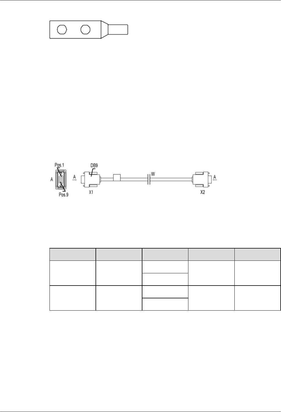
Figure 2-21 2-hole terminal
Installation Position
One end of the PGND cable is connected to the grounding bolt on the SRXU, and the other end
is connected to the grounding bolt on the RRU3804.
2.4.2 Power Cable of the SRXU
The SRXU uses a shielded DC power cable. The cable feeds power from the RRU3804 to the
SRXU.
Appearance
Both ends of the cable are waterproof DB9 connectors, as shown in Figure 2-22.
Figure 2-22 DC power cable
Pin Assignment
Table 2-22 describes the pin assignment for the wires of the DC power cable.
Table 2-22 Pin assignment for the wires of the DC power cable
X1 End X2 End Wire Color Wire Type Remarks
X1.6 X2.6 White/blue Twisted pair DC power cable
Blue
X1.7 X2.7 White/orange Twisted pair GND
Orange
Installation Position
One end of the DC power cable is connected to the RET/PWR_SRXU port at the bottom of the
RRU3804, and the other end is connected to the PWR_SRXU socket at the bottom of the SRXU.
2.4.3 AISG Multi-Wire Cable of the RRU3804/SRXU
The five-meter-long AISG multi-wire cable connects the RRU3804/SRXU to the Remote
Control Unit (RCU). If both RRU3804 and SRXU are installed, the AISG multi-wire cable only
connects the SRXU and the RCU. This cable is optional.
2 RRU3804 and SRXU Hardware
RRU3804
User Guide
2-28 Huawei Technologies Proprietary Issue 01 (2007-11-29)
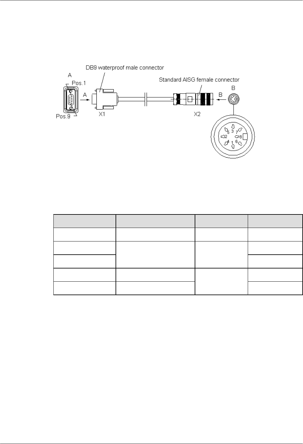
Appearance
One end of the AISG multi-wire cable is a waterproof DB9 connector, and the other end is a
standard AISG female connector, as shown in Figure 2-23.
Figure 2-23 AISG multi-wire cable
Pin Assignment
Table 2-23 describes the pin assignment for the wires of the AISG multi-wire cable.
Table 2-23 Pin assignment for the wires of the AISG multi-wire cable
X1 End X2 End Wire Type Remarks
X1.1 X2.1 Twisted pair +12 V
X1.7 X2.7 Twisted pair DC-GND
X1.9 AISG_Switch
X1.3 X2.3 Twisted pair RS485 -
X1.5 X2.5 RS485 +
Installation Position
If only the RRU3804 is installed, the waterproof DB9 connector is linked to the RET/
PWR_SRXU port at the bottom of the RRU3804, and the standard AISG female connector is
linked to the corresponding connector on the RCU or to the AISG extension cable.
If both the RRU3804 and the SRXU are installed, the waterproof DB9 connector is linked to the
RET port at the bottom of the SRXU, and the standard AISG female connector is linked to the
corresponding connector on the RCU or to the AISG extension cable.
2.4.4 AISG Extension Cable of the RRU3804/SRXU
When the distance between the RCU and the RRU3804/SRXU is longer than 5 m, the AISG
multi-wire cable is not long enough to cover the distance and the AISG extension cable is used.
The AISG extension cable is 15 m long.
RRU3804
User Guide 2 RRU3804 and SRXU Hardware
Issue 01 (2007-11-29) Huawei Technologies Proprietary 2-29
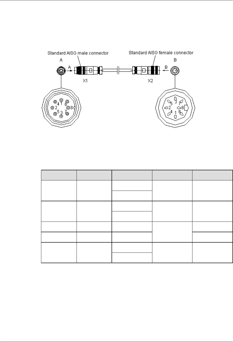
Appearance
One end of the AISG extension cable is a standard AISG male connector, and the other end is
a standard AISG female connector, as shown in Figure 2-24.
Figure 2-24 AISG extension cable
Pin Assignment
Table 2-24 describes the pin assignment for the wires of the AISG extension cable.
Table 2-24 Pin assignment for the wires of the AISG extension cable
X1 End X2 End Wire Color Wire Type Remarks
X1.1 X2.1 White/blue Twisted pair +12 V
Blue
X1.7 X2.7 White/orange Twisted pair DC Return A
Orange
X1.3 X2.3 White/green Twisted pair RS485 B
X1.5 X2.5 Green RS485 A
X1.6 X2.6 White/brown Twisted pair +24 V
Brown
Installation Position
The AISG female connector is linked to the corresponding connector on the RCU, and the AISG
male connector is linked to the AISG female connector of the AISG multi-wire cable.
2.4.5 BBU3806-RRU/SRXU CPRI Optical Cable
The CPRI optical cable transmits CPRI signals between BBU3806 and RRU3801C, between
BBU3806 and RRU3804, and between RRU3804 and SRXU.
2 RRU3804 and SRXU Hardware
RRU3804
User Guide
2-30 Huawei Technologies Proprietary Issue 01 (2007-11-29)
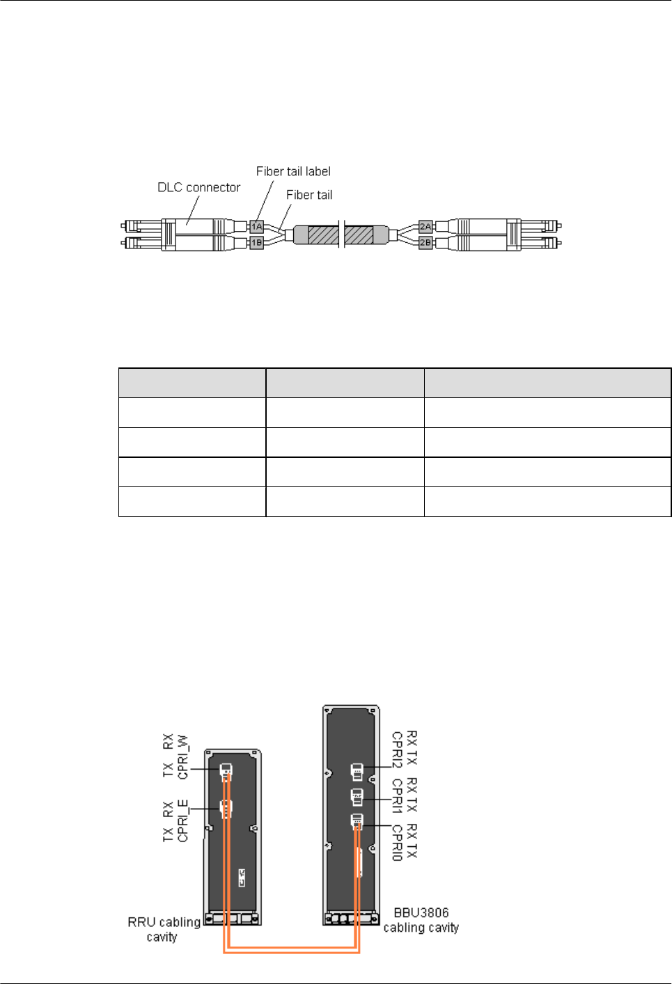
Appearance
The CPRI optical cable is a multi-mode 2-wire cable with DLC connectors at both ends.
Figure 2-25 shows the CPRI optical cable.
Figure 2-25 CPRI optical cable
Pin Assignment
Table 2-25 describes the pin assignment for the fiber tails.
Table 2-25 Pin assignment for the fiber tails
Label Color Connect to...
1A Orange RX port on the RRU
1B Gray TX port on the RRU
2A Orange TX port on the BBU3806
2B Gray RX port on the BBU3806
Connections of BBU3806-RRU CRPI Optical Cable in Typical Configurations
The connections of the CPRI optical cable between the BBU3806 and the RRU depend on
specific networking modes.
Figure 2-26 and Figure 2-27 show the connections of the optical cable between the BBU3806
and the RRU in two typical configurations.
Figure 2-26 Connecting the CPRI optical cable in 1 x 1 configuration (no TX diversity)
RRU3804
User Guide 2 RRU3804 and SRXU Hardware
Issue 01 (2007-11-29) Huawei Technologies Proprietary 2-31
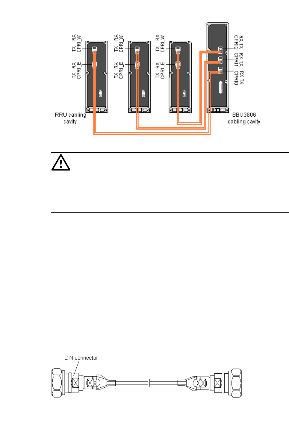
Figure 2-27 Connecting the CPRI optical cable in 3 x 1 configuration (no TX diversity)
CAUTION
To connect the optical cable, adhere to the following rules:
lThe TX port on the BBU3806 is connected to the RX port on the RRU.
lThe RX port on the BBU3806 is connected to the TX port on the RRU.
2.4.6 RF Jumper of the RRU3804/SRXU
The RF jumper of the RRU3804/SRXU is of two types: antenna jumper and interconnect jumper.
The interconnect jumper is optional, depending on the site configuration.
Antenna Jumper of the RRU3804/SRXU
The antenna jumper transmits and receives RF signals.
Appearance
Both ends of the antenna jumper have DIN connectors, as shown in Figure 2-28.
Figure 2-28 Antenna jumper
2 RRU3804 and SRXU Hardware
RRU3804
User Guide
2-32 Huawei Technologies Proprietary Issue 01 (2007-11-29)
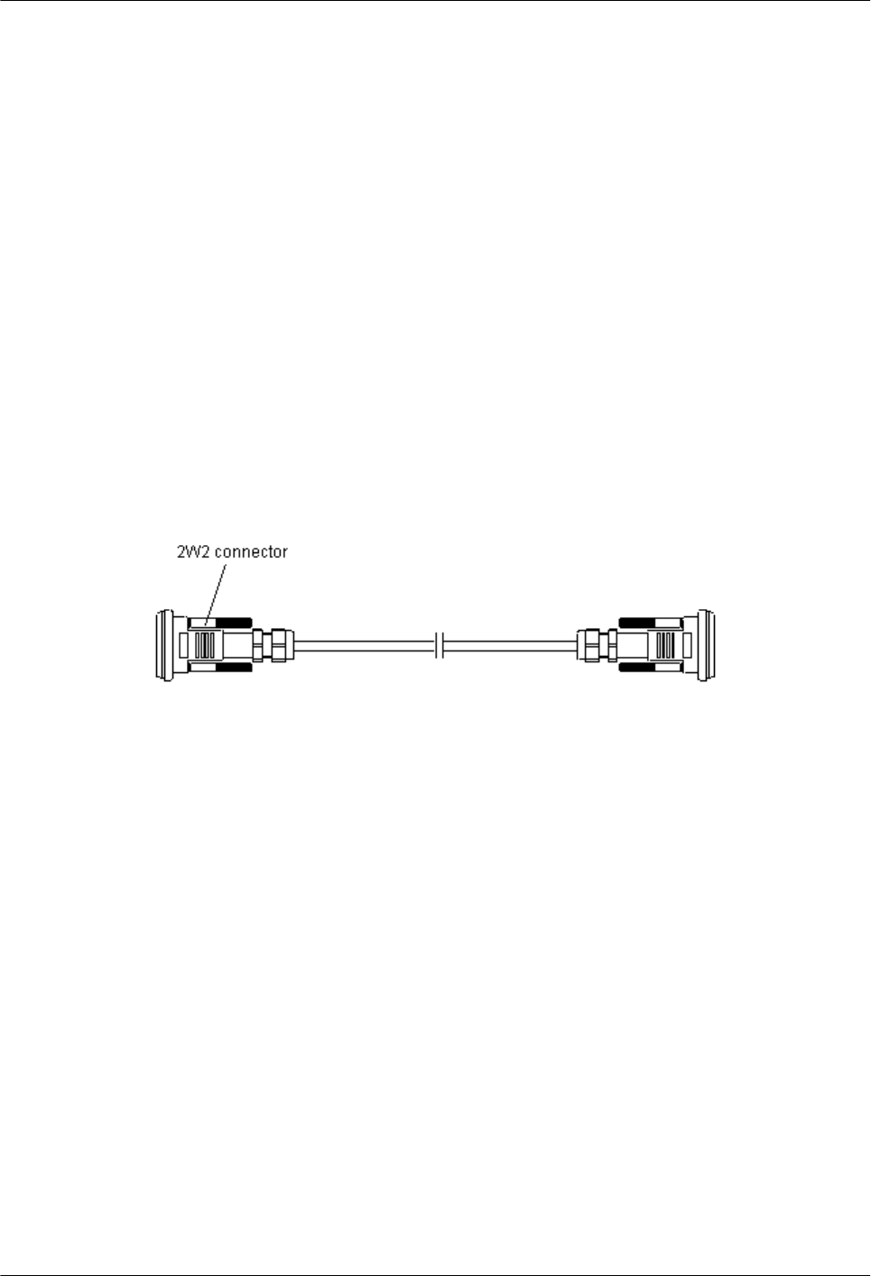
Installation Position
The antenna jumper with indefinite length is selected according to the distance between the
antenna and the RRU3804/SRXU. Connectors are made on site.
lWhen the distance between the antenna and the RRU3804/SRXU is shorter than 14 m, the
RRU3804/SRXU is directly connected to the antenna through the antenna jumper.
lWhen the distance between the antenna and the RRU3804/SRXU is longer than 14 m, the
antenna jumper should be shorter than 2 m. If you prepare the jumper by yourself, it is
recommended that the antenna jumper be 2 m long at most. Ensure that the antenna jumper
is connected to the feeder before being connected to the RRU3804/SRXU and the antenna.
Interconnect Jumper of the RRU3804/SRXU
The interconnect jumper transmits RF signals between two RRU3804s/SRXUs.
Appearance
The interconnect jumper is 2 m long, and both ends have 2W2 connectors, as shown in Figure
2-29.
Figure 2-29 Interconnect jumper
Installation Position
The 2W2 connectors at the two ends of the interconnect jumper are linked to the ports labeled
RX_IN/OUT on two RRU3804s/SRXUs respectively.
RRU3804
User Guide 2 RRU3804 and SRXU Hardware
Issue 01 (2007-11-29) Huawei Technologies Proprietary 2-33

3 Installing RRU3804 and SRXU Hardware
About This Chapter
This describes how to install the hardware, route the cables, and check the hardware installation
of the RRU3804 and SRXU.
3.1 Information About the Installation
This describes the installation modes and space requirements of the RRU3804 and SRXU.
3.2 Procedure for Installing the RRU3804 and SRXU
The procedure for installing the RRU3804 and SRXU varies with the installation scenarios. The
procedure involves making preparations, installing the RRU3804 and SRXU, connecting related
cables, checking the hardware installation, and installing the housing of the RRU3804 and
SRXU.
3.3 Preparing for DBS3800 Installation
Before installing the DBS3800, acquaint yourself with the type, quantity, and installation
position of the equipment to be installed. Then unpack the DBS3800 and prepare tools and
instruments for the installation.
3.4 Installing the RRU3804 on the Ground or Rooftop
When the RRU3804 needs to be installed on the ground or rooftop, it supports one-module, two-
module centralized, and three-module centralized installation modes.
3.5 Installing the RRU3804 on the Tower
Before installing the RRU3804 on the tower, you need to assemble the parts and then lift them
up to the tower.
3.6 Installing the SRXU
This describes how to install the SRXU on the RRU3804 in one-module, two-module
centralized, or three-module centralized installation mode.
3.7 Installing RRU3804 and SRXU Cables
This describes how to install the cables of the RRU3804 and SRXU, remove and install the cover
plate of the RRU3804 or SRXU cabling cavity.
3.8 Checking RRU3804 and SRXU Hardware Installation
This describes how to check the power-on status, hardware installation, and field cleanliness for
the RRU3804 and SRXU.
RRU3804
User Guide 3 Installing RRU3804 and SRXU Hardware
Issue 01 (2007-11-29) Huawei Technologies Proprietary 3-1

3.9 Installing the Housing of the RRU3804 and SRXU
After the SRXU is fixed to the RRU3804, install the housing after checking the hardware
installation.
3 Installing RRU3804 and SRXU Hardware
RRU3804
User Guide
3-2 Huawei Technologies Proprietary Issue 01 (2007-11-29)
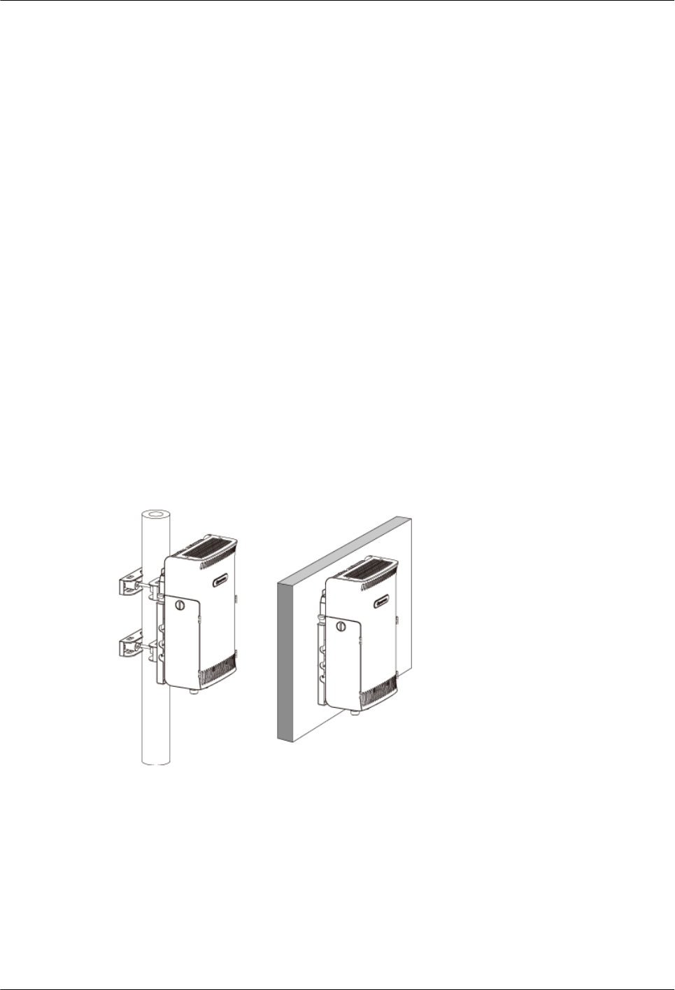
3.1 Information About the Installation
This describes the installation modes and space requirements of the RRU3804 and SRXU.
3.1.1 Installation Modes of the RRU3804 and SRXU
The RRU3804 supports one-module, two-module centralized, and three-module centralized
installation modes. It can be mounted on a metal pole or wall. The SRXU can be fixed to the
RRU3804 as required. The quantity of the SRXUs is the same as that of the RRU3804s.
3.1.2 Space Requirements of the RRU3804 and SRXU
In different installation modes, the RRU3804 and SRXU have the minimal space requirements
for cabling and OM. Based on the engineering practice, Huawei offers the recommended space
requirements.
3.1.1 Installation Modes of the RRU3804 and SRXU
The RRU3804 supports one-module, two-module centralized, and three-module centralized
installation modes. It can be mounted on a metal pole or wall. The SRXU can be fixed to the
RRU3804 as required. The quantity of the SRXUs is the same as that of the RRU3804s.
Installation Modes of One RRU3804
Figure 3-1 shows the installation modes of one RRU3804.
Figure 3-1 Installation modes of one RRU3804
Installation Modes of One RRU3804 with One SRXU
Figure 3-2 shows the installation modes of one RRU3804 with one SRXU.
RRU3804
User Guide 3 Installing RRU3804 and SRXU Hardware
Issue 01 (2007-11-29) Huawei Technologies Proprietary 3-3
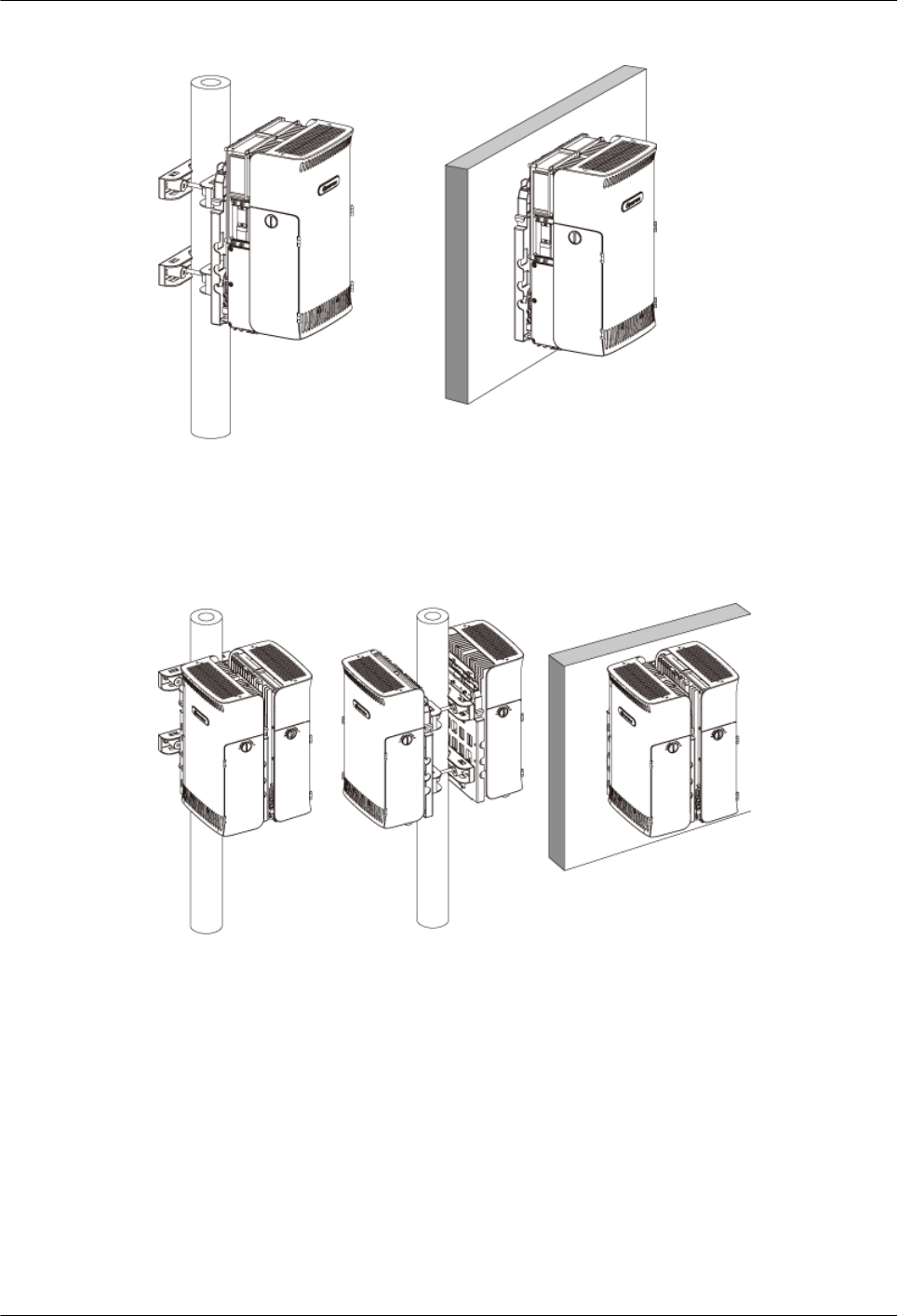
Figure 3-2 Installation modes of one RRU3804 with one SRXU
Installation Modes of Two RRU3804s
Figure 3-3 shows the installation modes of two RRU3804s.
Figure 3-3 Installation modes of two RRU3804s
Installation Modes of Two RRU3804s with Two SRXUs
Figure 3-4 shows the installation modes of two RRU3804s with two SRXUs.
3 Installing RRU3804 and SRXU Hardware
RRU3804
User Guide
3-4 Huawei Technologies Proprietary Issue 01 (2007-11-29)
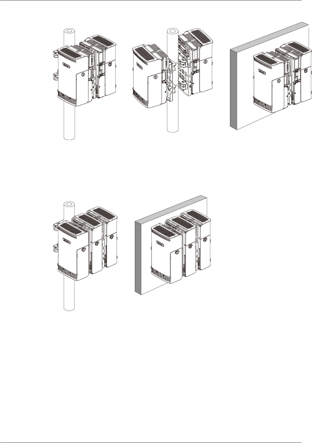
Figure 3-4 Installation modes of two RRU3804s with two SRXUs
Installation Modes of Three RRU3804s
Figure 3-5 shows the installation modes of three RRU3804s.
Figure 3-5 Installation modes of three RRU3804s
Installation Modes of Three RRU3804s with Three SRXUs
Figure 3-6 shows the installation modes of three RRU3804s with three SRXUs.
RRU3804
User Guide 3 Installing RRU3804 and SRXU Hardware
Issue 01 (2007-11-29) Huawei Technologies Proprietary 3-5
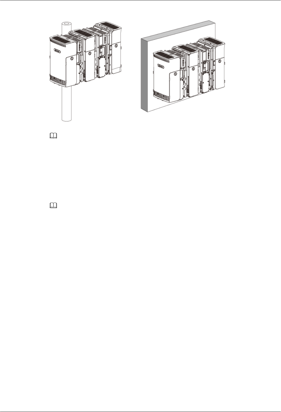
Figure 3-6 Installation modes of three RRU3804s with three SRXUs
NOTE
The RRU3804 can also be installed in an indoor centralized rack. For details about how to install the
RRU3804 in the indoor centralized rack, refer to the Indoor Centralized Rack Installation Guide.
3.1.2 Space Requirements of the RRU3804 and SRXU
In different installation modes, the RRU3804 and SRXU have the minimal space requirements
for cabling and OM. Based on the engineering practice, Huawei offers the recommended space
requirements.
NOTE
The following figures related to the space requirements assume that the cabling cavities are on the left side
of the RRU3804 and SRXU. If the RRU3804 and SRXU are installed with the cabling cavities on the right,
the horizontal space requirements are opposite to what are shown in the figures.
Space Requirements of One RRU3804 with and Without the SRXU
Figure 3-7 shows the recommended space requirements of one RRU3804 with and without the
SRXU.
3 Installing RRU3804 and SRXU Hardware
RRU3804
User Guide
3-6 Huawei Technologies Proprietary Issue 01 (2007-11-29)
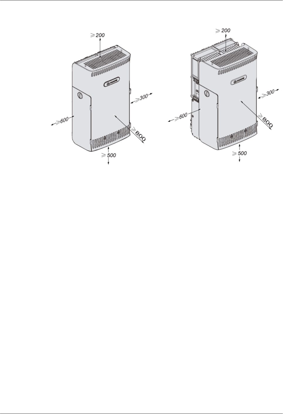
Figure 3-7 Recommended space requirements of one RRU3804 with and without the SRXU
(unit: mm)
The recommended space around the equipment is as follows:
lAt least 500 mm under the equipment for cabling. It is recommended that the space is 1,200
mm between the bottom and the ground for easy maintenance.
lAt least 800 mm in front of the equipment for maintenance.
lAt least 200 mm above the equipment for maintenance.
lAt least 600 mm on the left of the equipment for maintenance.
lAt least 300 mm on the right of the equipment for maintenance.
lRegardless of whether the SRXU is fixed to the RRU3804, the space requirements are the
same.
Figure 3-8 shows the minimal space requirements of one RRU3804 with and without the SRXU.
RRU3804
User Guide 3 Installing RRU3804 and SRXU Hardware
Issue 01 (2007-11-29) Huawei Technologies Proprietary 3-7
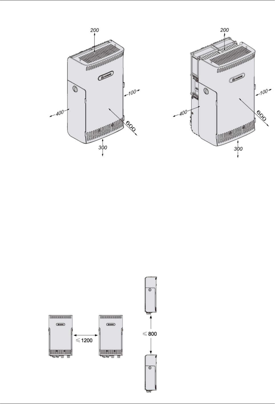
Figure 3-8 Minimal space requirements of one RRU3804 with and without the SRXU (unit:
mm)
The minimal space around the equipment is as follows:
l300 mm under the equipment for cabling. It is recommended that the space is 1,200 mm
between the bottom and the ground for easy maintenance.
l600 mm in front of the equipment for maintenance.
l200 mm above the equipment for maintenance.
l400 mm on the left of the equipment for maintenance.
l100 mm on the right of the equipment for maintenance.
When two RRU3804s need to be combined, the space between the two RRU3804s should stay
within the range shown in Figure 3-9.
Figure 3-9 Space requirements of two combined RRU3804s (unit: mm)
3 Installing RRU3804 and SRXU Hardware
RRU3804
User Guide
3-8 Huawei Technologies Proprietary Issue 01 (2007-11-29)
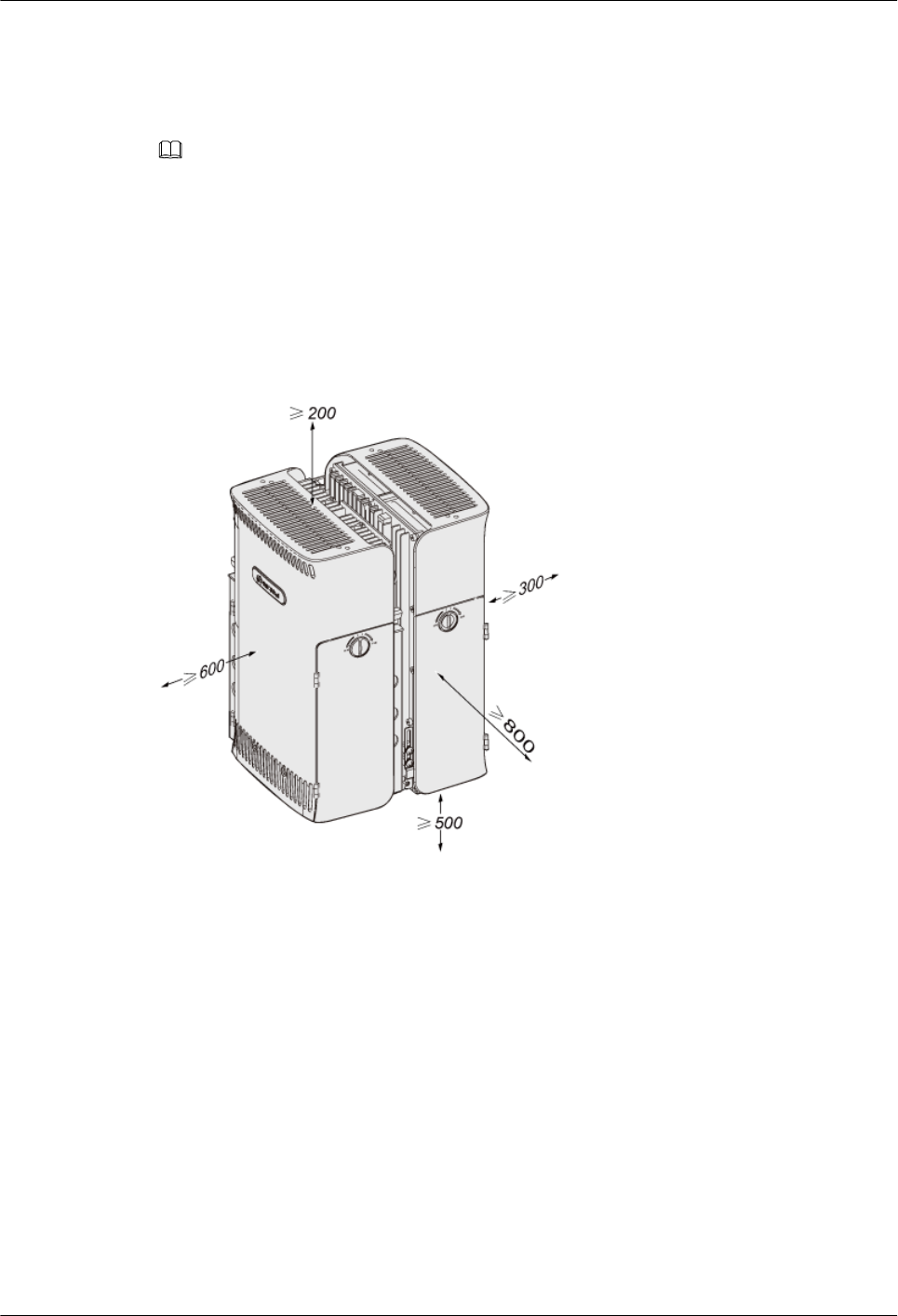
The space between the two RRU3804s is as follows:
lWhen two RRU3804s are installed horizontally, the space is 1,200 mm at most.
lWhen two RRU3804s are installed vertically, the space is 800 mm at most.
NOTE
The space requirements of two combined SRXUs are the same as those of two combined RRU3804s.
Space Requirements of Multiple RRU3804s with and Without the SRXUs
Figure 3-10 shows the recommended space requirements of multiple RRU3804s with and
without the SRXUs.
Figure 3-10 Recommended space requirements of multiple RRU3804s with and without the
SRXUs (unit: mm)
The recommended space around the equipment is as follows:
lAt least 500 mm under the equipment for cabling. It is recommended that the space is 1,200
mm between the bottom and the ground for easy maintenance.
lAt least 800 mm in front of the equipment for maintenance.
lAt least 200 mm above the equipment for maintenance.
lAt least 600 mm on the left of the equipment for maintenance.
lAt least 300 mm on the right of the equipment for maintenance.
lRegardless of whether the SRXUs are fixed to the RRU3804s, the space requirements are
the same.
lRegardless of whether the RRU3804s are in two-module or three-module centralized
installation mode, the space requirements are the same.
Figure 3-11 shows the minimal space requirements of multiple RRU3804s with and without the
SRXUs.
RRU3804
User Guide 3 Installing RRU3804 and SRXU Hardware
Issue 01 (2007-11-29) Huawei Technologies Proprietary 3-9
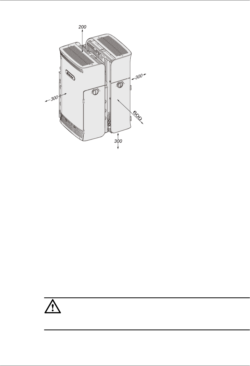
Figure 3-11 Minimal space requirements of multiple RRU3804s with and without the SRXUs
(unit: mm)
The minimal space around the equipment is as follows:
l300 mm under the equipment for cabling. It is recommended that the space is 1,200 mm
between the bottom and the ground for easy maintenance.
l600 mm in front of the equipment for maintenance.
l200 mm above the equipment for maintenance.
l300 mm on the left of the equipment for maintenance.
l300 mm on the right of the equipment for maintenance.
3.2 Procedure for Installing the RRU3804 and SRXU
The procedure for installing the RRU3804 and SRXU varies with the installation scenarios. The
procedure involves making preparations, installing the RRU3804 and SRXU, connecting related
cables, checking the hardware installation, and installing the housing of the RRU3804 and
SRXU.
Context
CAUTION
After the NodeB is installed, it must be powered on within 48 hours.
3 Installing RRU3804 and SRXU Hardware
RRU3804
User Guide
3-10 Huawei Technologies Proprietary Issue 01 (2007-11-29)
NOTE
Contact Huawei engineers for confirmation if:
lYou choose to prepare the devices, cables, and connectors by yourself.
lYou need to shorten the cable of a specified length.
Procedure
Step 1 Unpack the RRU3804 and SRXU, check the items in the package, and have tools and instruments
ready. For details, refer to 3.3 Preparing for DBS3800 Installation.
Step 2 Install the RRU3804. The installation mode of the RRU3804 varies with the installation
scenarios.
l3.4 Installing the RRU3804 on the Ground or Rooftop
Condition Action
Only one RRU3804 needs to be installed. Go to 3.4.1 Installing a Single RRU3804.
Two RRU3804s need to be installed. Go to 3.4.2 Installing Two RRU3804s.
Three RRU3804s need to be installed. Go to 3.4.3 Installing Three RRU3804s.
l3.5 Installing the RRU3804 on the Tower
Step 3 Check whether the SRXU needs to be installed. Perform the next step accordingly.
Condition Action
The SRXU needs to be installed. Go to Step 4.
The SRXU does not need to be installed. Go to Step 5.
Step 4 Install the SRXU. For details, refer to 3.6 Installing the SRXU.
Step 5 Install RRU3804 and SRXU cables. For details, refer to 3.7 Installing RRU3804 and SRXU
Cables.
Step 6 Check RRU3804 and SRXU hardware installation. For details, refer to 3.8 Checking RRU3804
and SRXU Hardware Installation.
Step 7 Install the housing of the RRU3804 and SRXU. For details, refer to 3.9 Installing the Housing
of the RRU3804 and SRXU.
----End
3.3 Preparing for DBS3800 Installation
Before installing the DBS3800, acquaint yourself with the type, quantity, and installation
position of the equipment to be installed. Then unpack the DBS3800 and prepare tools and
instruments for the installation.
3.3.1 Unpacking the DBS3800
RRU3804
User Guide 3 Installing RRU3804 and SRXU Hardware
Issue 01 (2007-11-29) Huawei Technologies Proprietary 3-11
This describes how to unpack the DBS3800 and check the items in the package.
3.3.2 Tools and Instruments for DBS3800 Installation
This describes general tools, special tools, and instruments required for the DBS3800
installation.
3.3.1 Unpacking the DBS3800
This describes how to unpack the DBS3800 and check the items in the package.
Context
NOTE
When transporting, moving, or installing the equipment, components, or parts, you must:
lPrevent them from colliding with doors, walls, shelves, or other objects.
lAvoid touching the uncoated metal surface of the equipment, components, or parts with sweat-soaked
or dirty gloves.
Procedure
Step 1 Check the quantity of components inside the carton according to the carton label.
If... Then...
The quantity matches the carton label, Go to Step 2.
The quantity does not match the carton
label,
Find the cause and contact Huawei local
office.
Step 2 Check whether the packing case is in good condition.
If... Then...
The packing case is in good condition, Go to Step 3.
The packing case is damaged or soaked, Find the cause and contact Huawei local office.
Step 3 Open the packing case. Check the shipped components according to the Packing List, and then
perform the next step according to the check result.
If... Then...
The shipped components match the Packing
List,
Sign the Packing List together with the
customer.
There is any short shipment, wrong
shipment, or equipment damage.
Fill in the Cargo Problems Report.
3 Installing RRU3804 and SRXU Hardware
RRU3804
User Guide
3-12 Huawei Technologies Proprietary Issue 01 (2007-11-29)

CAUTION
lTo protect the equipment and to find out the cause in the case of goods damage, store
the equipment and the unpacked cases and materials inside the equipment room.
lTake photos of the storage environment, rusted or corroded devices, and packing cases
and materials, and then file the photos.
----End
3.3.2 Tools and Instruments for DBS3800 Installation
This describes general tools, special tools, and instruments required for the DBS3800
installation.
Table 3-1 lists the tools and instruments necessary for the DBS3800 installation.
Table 3-1 Tools and instruments
General Tools Measuring
tools
Long tape, 50 m ribbon tape, 5 m measuring tape, 400
mm level bar, level instrument
Marking
tools
Marking pen, ink fountain, pencil
Drilling tools Percussion drill with matching bits of Ф6, Ф8, Ф10, Ф12,
Ф14, and Ф16, cleaner
Fastening
tools
Straight screwdrivers (M3 to M6)
Cross screwdrivers (M3 to M6)
Adjustable wrench
Socket wrenches (M6, M8, M10, M12, M14, M17, M19)
Double offset ring wrenches (M6, M8, M10, M12, M14,
M17, M19)
Combination wrenches (M17 and M19)
Long-arm wrench
Pliers Sharp nose pliers, diagonal pliers, pincer pliers, electric
hand drill, file, handsaw, crowbar, rubber hammer, claw
hammer
Auxiliary
tools
Brush, tweezers, paper knife, bellows, plumb, soldering
iron, solder wires, fork, ladder, heat blower, solder
absorber, insulating tape
Special Tools An earth resistance meter, ESD wrist strap, a pair of ESD gloves, cable
peeler, clamping pliers, a feeder cutter, a pair of crimping pliers for SMB,
RJ-45 crimping pliers, wire punchdown tool, wire cutter, a non-
conductive screwdriver, safety knife, peeler for 75-ohm coaxial cables, a
pair of connector crimping pliers for 75-ohm coaxial cables, a pair of
multi-purpose crimping pliers
RRU3804
User Guide 3 Installing RRU3804 and SRXU Hardware
Issue 01 (2007-11-29) Huawei Technologies Proprietary 3-13
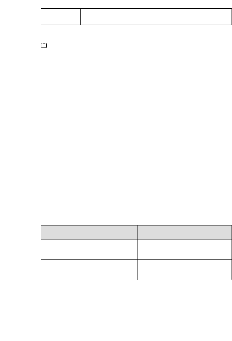
Instruments Multimeter, 500 V megohmmeter (for insulation resistance), BER tester,
optical power meter
NOTE
The instruments must be checked and certified.
3.4 Installing the RRU3804 on the Ground or Rooftop
When the RRU3804 needs to be installed on the ground or rooftop, it supports one-module, two-
module centralized, and three-module centralized installation modes.
3.4.1 Installing a Single RRU3804
This describes how to install a single RRU3804 module and its mounting plate. The single
RRU3804 can be installed on a metal pole or wall.
3.4.2 Installing Two RRU3804s
This describes how to install two RRU3804 modules and their mounting plates. The two
RRU3804s can be installed on a metal pole or wall.
3.4.3 Installing Three RRU3804s
This describes how to install three RRU3804 modules and their mounting plates. The three
RRU3804s can be installed on a metal pole or wall.
3.4.1 Installing a Single RRU3804
This describes how to install a single RRU3804 module and its mounting plate. The single
RRU3804 can be installed on a metal pole or wall.
Procedure
Step 1 Install the mounting plate of the RRU3804. The operation varies with the installation mode.
Condition Action
The RRU3804 needs to be installed on a
metal pole.
Install the mounting plate of the single
RRU3804 on the metal pole.
The RRU3804 needs to be installed on a wall. Install the mounting plate of the single
RRU3804 on the wall.
Step 2 Install the single RRU3804 module. For details, refer to 3.4.1.3 Installing the Single RRU3804
Module.
----End
Installing the Mounting Plate of the Single RRU3804 on the Metal Pole
This describes how to install the mounting plate on the metal pole.
3 Installing RRU3804 and SRXU Hardware
RRU3804
User Guide
3-14 Huawei Technologies Proprietary Issue 01 (2007-11-29)
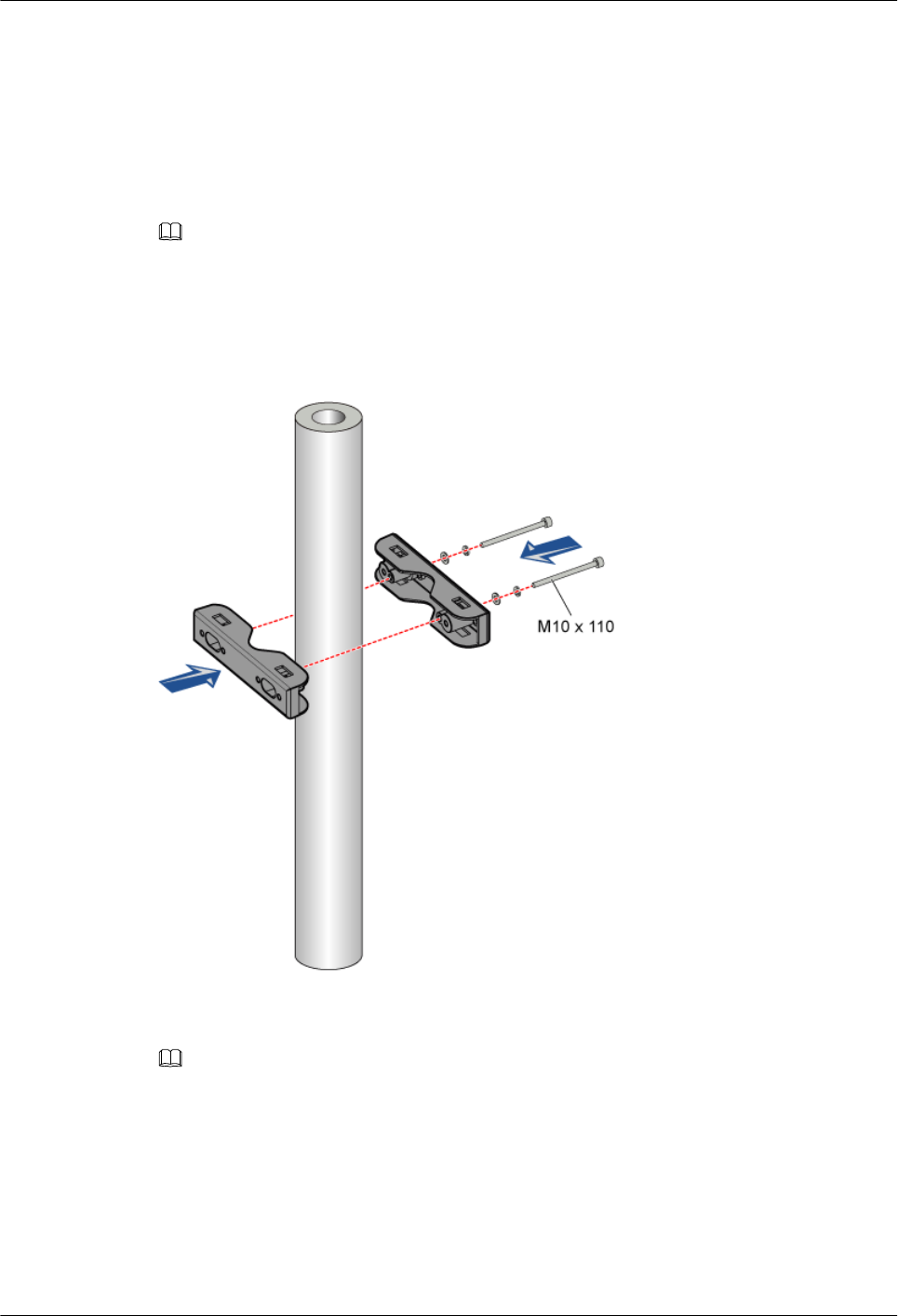
Prerequisite
The metal pole is ready and the pole diameter stays within the range of 60 mm to 114 mm.
Procedure
Step 1 Determine the position of the mounting plate by referring to the engineering design and 3.1.2
Space Requirements of the RRU3804 and SRXU.
NOTE
The upper fixture assembly should be 1,200 mm to 1,600 mm above the ground or rooftop.
Step 2 Mount the upper fixture assembly on the metal pole. Ensure that the four ends of the fixture
assembly are on the same plane, as shown in Figure 3-12.
Figure 3-12 Mounting the upper fixture assembly
Step 3 Use the level bar to check whether the four ends of the fixture assembly are on the same plane.
Use the tape measure to check whether the two pole fixtures are parallel.
NOTE
If the difference between L1 and L2, as shown in Figure 3-13, is beyond ±1 mm, the two pole fixtures are
not parallel.
RRU3804
User Guide 3 Installing RRU3804 and SRXU Hardware
Issue 01 (2007-11-29) Huawei Technologies Proprietary 3-15
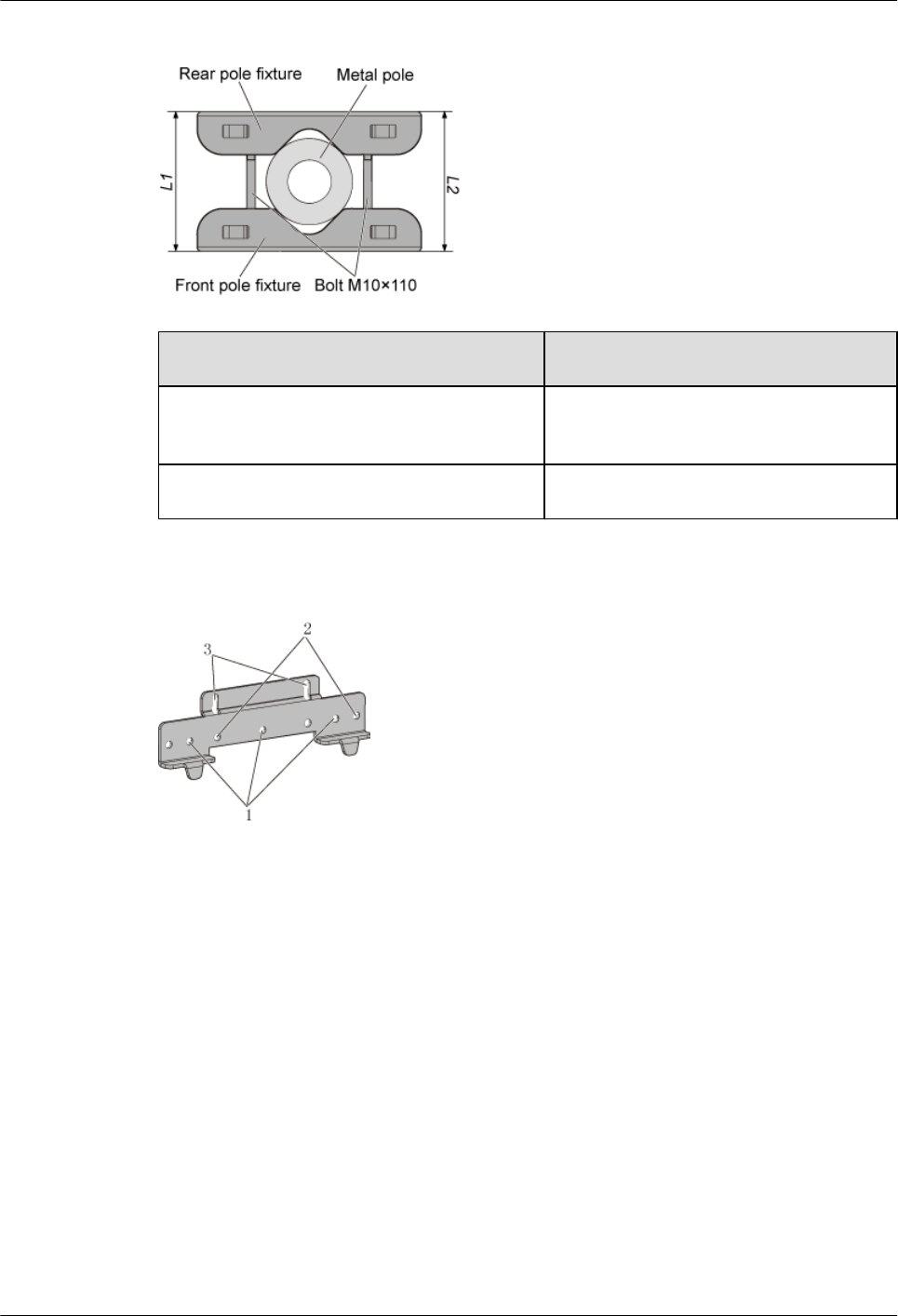
Figure 3-13 Measuring L1 and L2
Condition Action
The pole fixtures are neither horizontal nor
parallel.
Go to Step 2 to adjust the fixture assembly.
The pole fixtures are horizontal and parallel. Go to Step 4.
Step 4 Use the holes numbered 1 in Figure 3-14.
Figure 3-14 Holes in the multi-purpose attachment plate
Step 5 Use three screws M6 x 20 to secure the multi-purpose attachment plate on the mounting plate,
as shown in Figure 3-15.
3 Installing RRU3804 and SRXU Hardware
RRU3804
User Guide
3-16 Huawei Technologies Proprietary Issue 01 (2007-11-29)
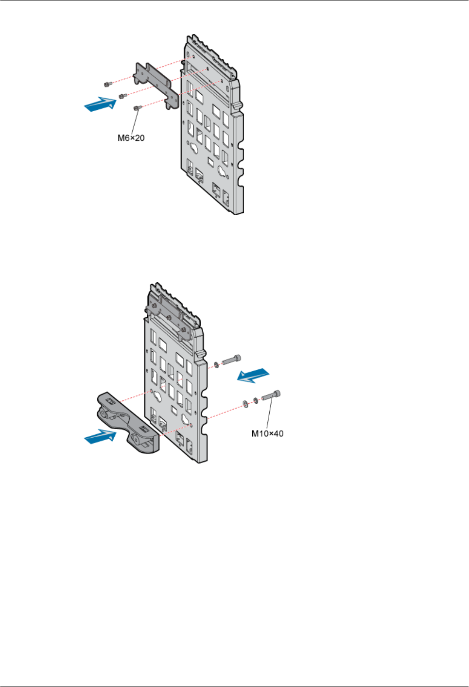
Figure 3-15 Securing the multi-purpose attachment plate on the mounting plate
Step 6 Install the third pole fixture on the mounting plate at the lower part of its back by fastening two
bolts M10 x 40, as shown in Figure 3-16.
Figure 3-16 Installing the third pole fixture
Step 7 Install the mounting plate by fitting the tabs on the mounting plate into the anchor slots in the
pole fixture, as shown in Figure 3-17.
RRU3804
User Guide 3 Installing RRU3804 and SRXU Hardware
Issue 01 (2007-11-29) Huawei Technologies Proprietary 3-17
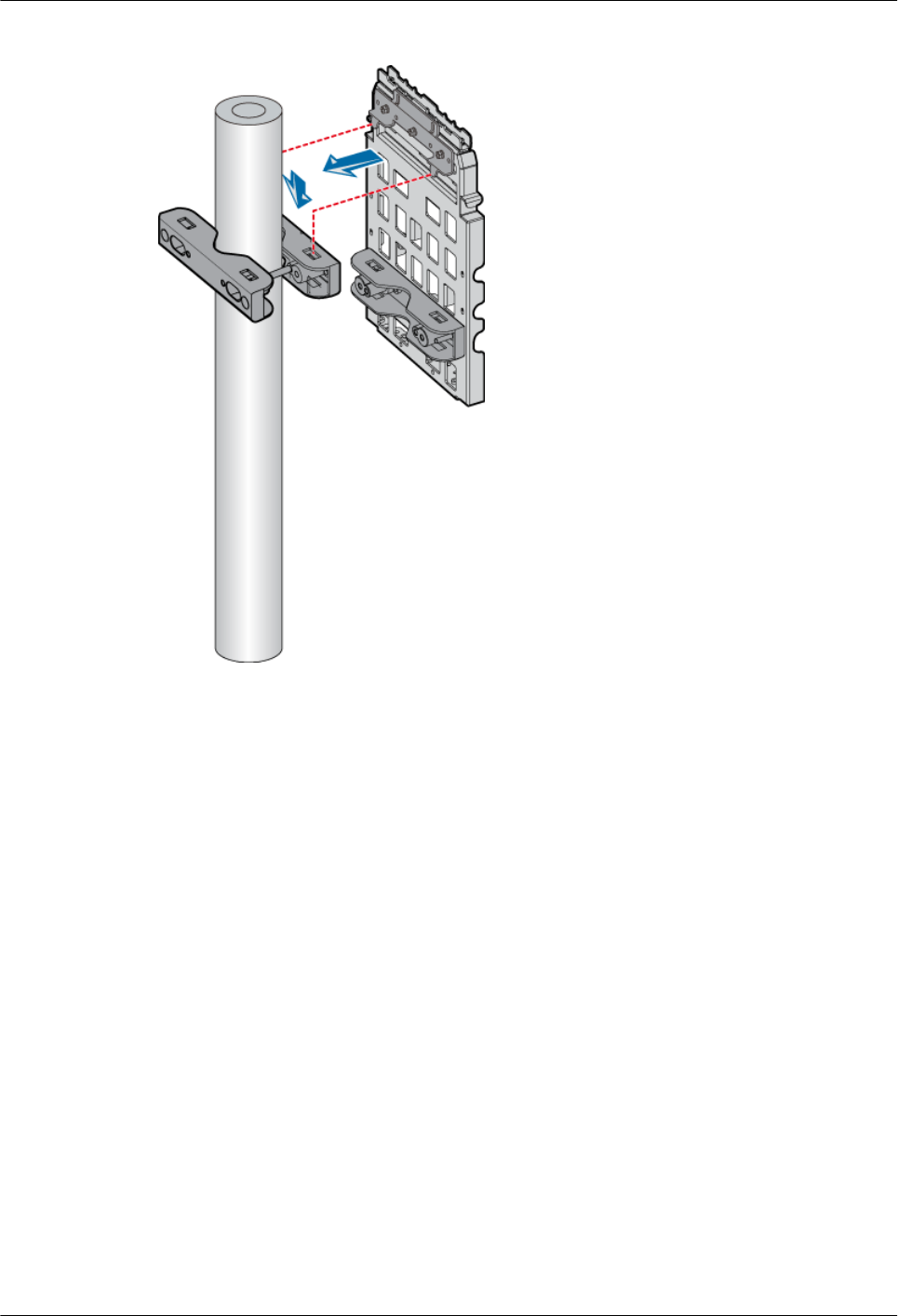
Figure 3-17 Installing the mounting plate
Step 8 Mount the fourth pole fixture to the metal pole by fastening two bolts M10 x 110 between the
third and the fourth pole fixtures, as shown in Figure 3-18.
3 Installing RRU3804 and SRXU Hardware
RRU3804
User Guide
3-18 Huawei Technologies Proprietary Issue 01 (2007-11-29)
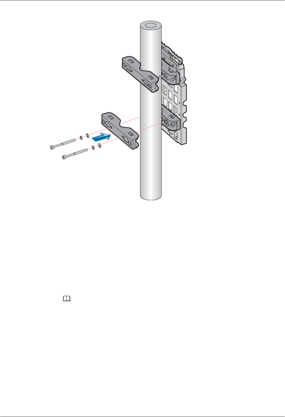
Figure 3-18 Mounting the lower fixture assembly
----End
Installing the Mounting Plate of the Single RRU3804 on the Wall
This describes how to install the mounting plate on the wall.
Procedure
Step 1 Determine the position of the mounting plate.
1. Determine the position of the mounting plate by referring to the engineering design and
3.1.2 Space Requirements of the RRU3804 and SRXU.
NOTE
The mounting plate should be 1,200 mm to 1,600 mm above the ground or rooftop.
2. Place the mounting plate against the wall, and then use the marking pen to mark the four
anchor points. You can also mark the anchor points by referring to the inter-hole distance
shown in Figure 3-19.
RRU3804
User Guide 3 Installing RRU3804 and SRXU Hardware
Issue 01 (2007-11-29) Huawei Technologies Proprietary 3-19
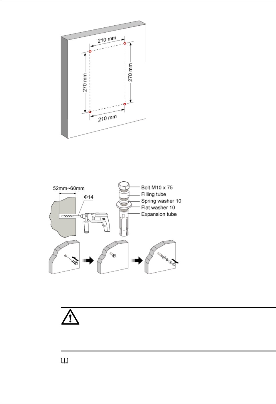
Figure 3-19 Determining the anchor points
Step 2 Drill holes on the anchor points and install the expansion bolt assembly, as shown in Figure
3-20.
Figure 3-20 Drilling holes and installing the expansion bolt assembly
1. Use the percussion drill with a Φ14 bit to drill four holes at the anchor points.
CAUTION
Protect yourself when drilling holes in the wall. Flying dust may hurt your eyes or you
may inhale the dust.
NOTE
The drilled holes must be 52 mm to 60 mm deep.
2. After the holes are drilled, use the cleaner to clean the dust both inside and around the holes.
If the inter-hole distance is too long or too short, locate and drill holes again.
3 Installing RRU3804 and SRXU Hardware
RRU3804
User Guide
3-20 Huawei Technologies Proprietary Issue 01 (2007-11-29)
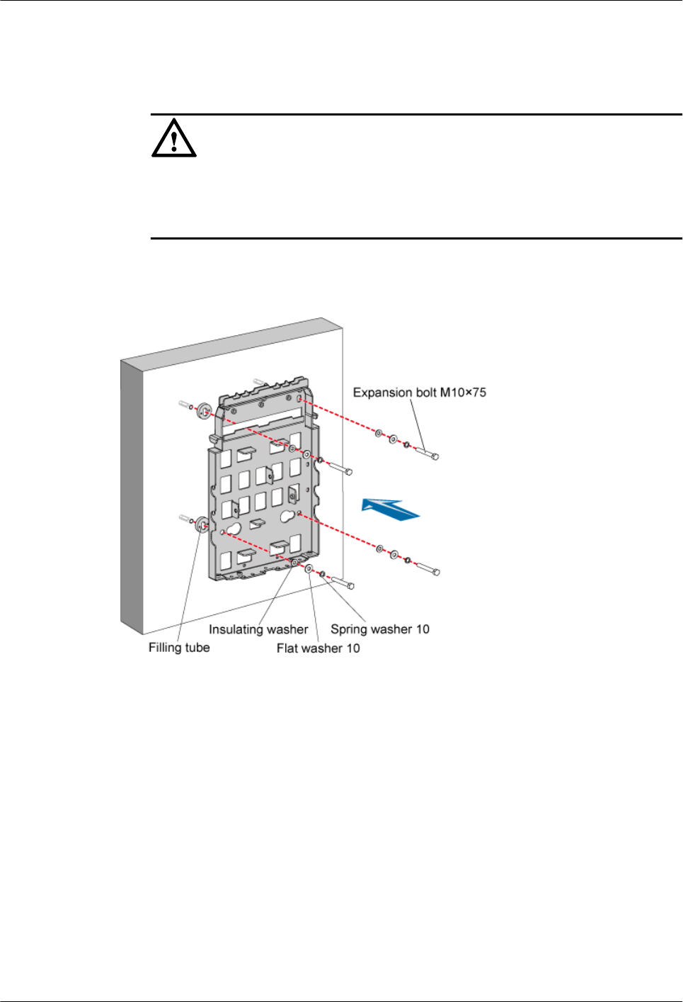
3. Screw the expansion bolt slightly and put it into the hole. Hammer the assembly until the
expansion tube is completely buried into the hole.
4. Remove the bolt M10 x 75, filling tube, spring washer 10, and flat washer 10 in turn.
CAUTION
lAfter disassembling the expansion bolt assembly, ensure that the top of the
expansion tube is completely buried into the wall. If it is not completely buried, the
mounting plate cannot be steady on the wall.
Step 3 Secure the mounting plate, as shown in Figure 3-21.
Figure 3-21 Securing the mounting plate
1. Place the mounting plate against the wall, and then align the mounting plate with the four
marked anchor points.
2. Lead each bolt M10 x 75 through the spring washer 10, flat washer 10, and insulating
washer in turn. Put each bolt into the expansion tube through the hole in the wall.
3. Use the wrench to fix the mounting plate to the wall by tightening the bolts clockwise.
----End
Installing the Single RRU3804 Module
This describes how to install the RRU3804 module on a metal pole. The procedures for installing
the module in pole or wall installation mode are the same.
Prerequisite
lThe RRU3804 mounting plate is installed.
RRU3804
User Guide 3 Installing RRU3804 and SRXU Hardware
Issue 01 (2007-11-29) Huawei Technologies Proprietary 3-21
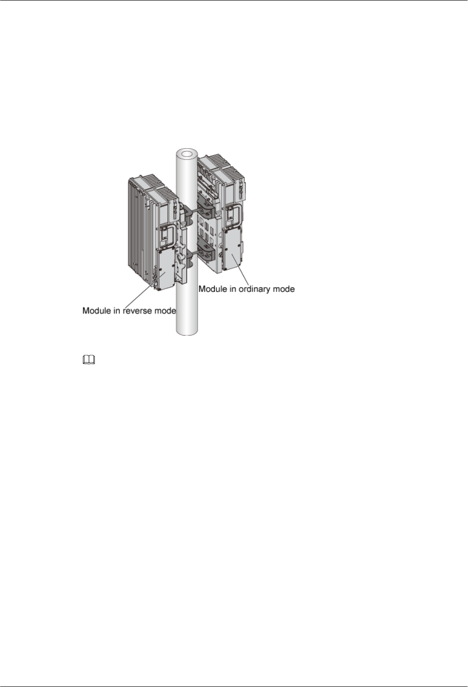
lIf the RRU3804 needs to be installed on a metal pole, the PGND cable of the metal pole is
connected.
Context
The RRU3804 module can be installed in either ordinary mode or reverse mode. In reverse mode,
the front side of the RRU3804 is fixed to the mounting plate. Figure 3-22 shows two RRU3804s
with one in ordinary mode and the other in reverse mode.
Figure 3-22 One RRU3804 in ordinary mode and the other in reverse mode
NOTE
lBefore installation, the plastic housing of the RRU3804 is already fixed to the module. The previous
figure omits the plastic housing for a better illustration of ordinary and reverse modes.
lBefore delivery, the plastic housing of the RRU3804 is fixed in the assumption that the RRU3804 needs
be installed in ordinary mode. If you want to install the RRU3804 in reverse mode, remove the plastic
housing first.
Procedure
Step 1 Use two screws M6 x 20 to secure the attachment plate on the module, as shown in Figure
3-23.
3 Installing RRU3804 and SRXU Hardware
RRU3804
User Guide
3-22 Huawei Technologies Proprietary Issue 01 (2007-11-29)
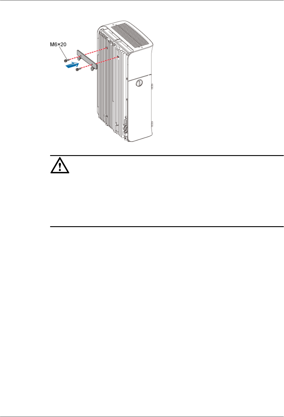
Figure 3-23 Securing the attachment plate
CAUTION
When installing the attachment plate, protect the plastic housing from being scratched.
lIf you find that the plastic housing is put face down when unpacking the RRU3804,
install the attachment plate before taking out the RRU3804.
lIf you find that the plastic housing is put face up, lay cardboards or packing bags on the
ground. Then, take out the RRU3804 and install the attachment plate.
Step 2 Fit the tabs on the attachment plate into the anchor slots of the mounting plate, as shown in
Figure 3-24.
RRU3804
User Guide 3 Installing RRU3804 and SRXU Hardware
Issue 01 (2007-11-29) Huawei Technologies Proprietary 3-23
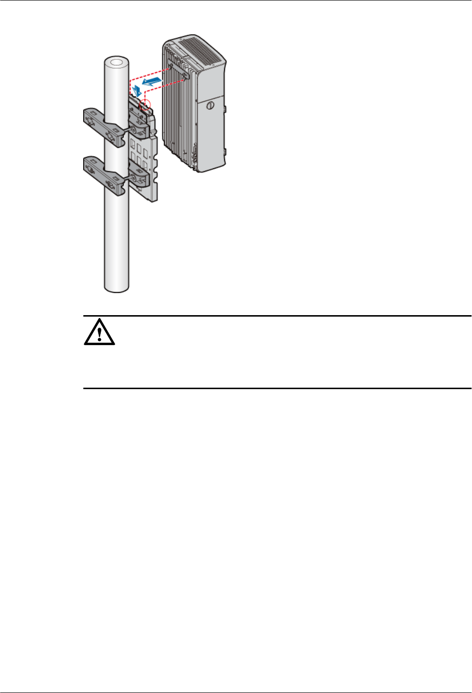
Figure 3-24 Installing the module
CAUTION
The tabs on the attachment plate must be fitted into the middle pair of anchor slots in the
mounting plate.
Step 3 Lead two screws M6 x 20 through the holes in the bottom of the module. Then, secure the module
on the mounting plate, as shown in Figure 3-25.
3 Installing RRU3804 and SRXU Hardware
RRU3804
User Guide
3-24 Huawei Technologies Proprietary Issue 01 (2007-11-29)
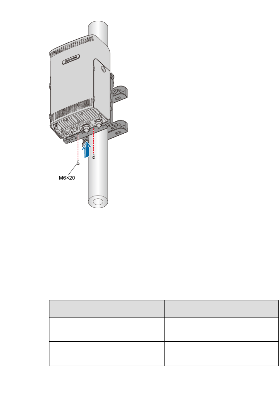
Figure 3-25 Securing the module
----End
3.4.2 Installing Two RRU3804s
This describes how to install two RRU3804 modules and their mounting plates. The two
RRU3804s can be installed on a metal pole or wall.
Procedure
Step 1 Install the mounting plate of the RRU3804. The operation varies with the installation mode.
Condition Action
The RRU3804 needs to be installed on a
metal pole.
Install the mounting plates of the two
RRU3804s on the metal pole .
The RRU3804 needs to be installed on a
wall.
Install the mounting plates of the two
RRU3804s on the wall .
Step 2 Install the two RRU3804 modules. For details, refer to 3.4.2.3 Installing the Two RRU3804
Modules.
----End
RRU3804
User Guide 3 Installing RRU3804 and SRXU Hardware
Issue 01 (2007-11-29) Huawei Technologies Proprietary 3-25
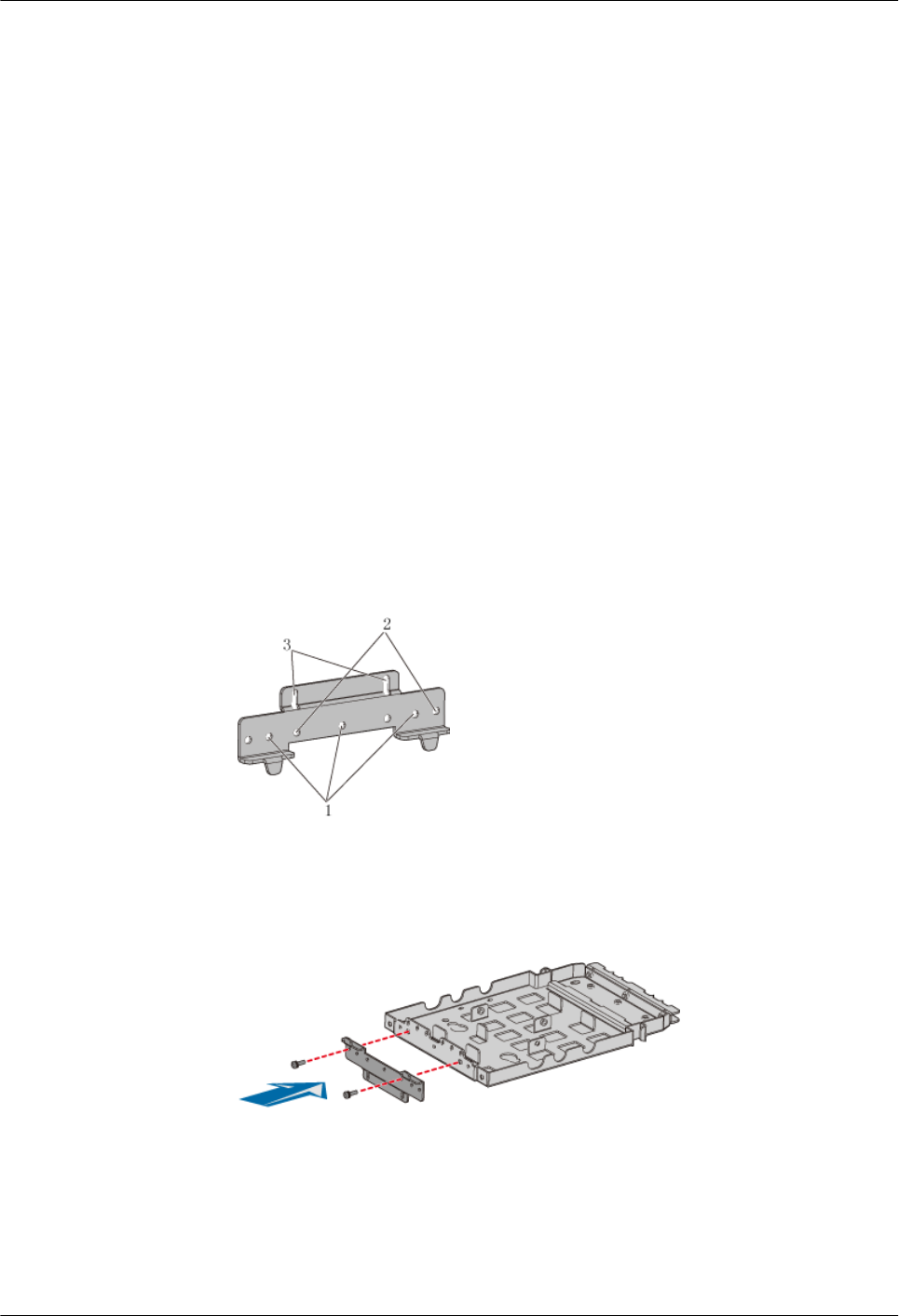
Installing the Mounting Plates of the Two RRU3804s on the Metal Pole
This describes how to install the mounting plates on the metal pole.
Prerequisite
The metal pole is ready and the pole diameter stays within the range of 60 mm to 114 mm.
Context
You can install the two RRU3804s on the metal pole by using the following methods. Select a
proper method depending on the field requirements.
lSide-mounted installation
lRear-mounted installation
Procedure
lSide-mounted installation
1. Install the first mounting plate by referring to 3.4.1.1 Installing the Mounting Plate
of the Single RRU3804 on the Metal Pole.
2. Use the holes numbered 2 in Figure 3-26.
Figure 3-26 Holes in the multi-purpose attachment plate
3. Use two screws M6 x 20 to secure the multi-purpose attachment plate at the bottom
of the second mounting plate, as shown in Figure 3-27.
Figure 3-27 Securing the multi-purpose attachment plate at the bottom of the second
mounting plate
4. Fit the tab on the left of the second mounting plate into the anchor slot in the first
mounting plate, as shown in Figure 3-28.
3 Installing RRU3804 and SRXU Hardware
RRU3804
User Guide
3-26 Huawei Technologies Proprietary Issue 01 (2007-11-29)