Huawei Technologies RRU3804B4 Distributed NodeB Remote Radio Unit User Manual User Guide
Huawei Technologies Co.,Ltd Distributed NodeB Remote Radio Unit User Guide
UserManual.wiki
>
Huawei Technologies
>
RRU3804B4 User Manual
>
User Manual 1
Contents
1.
User Manual 1
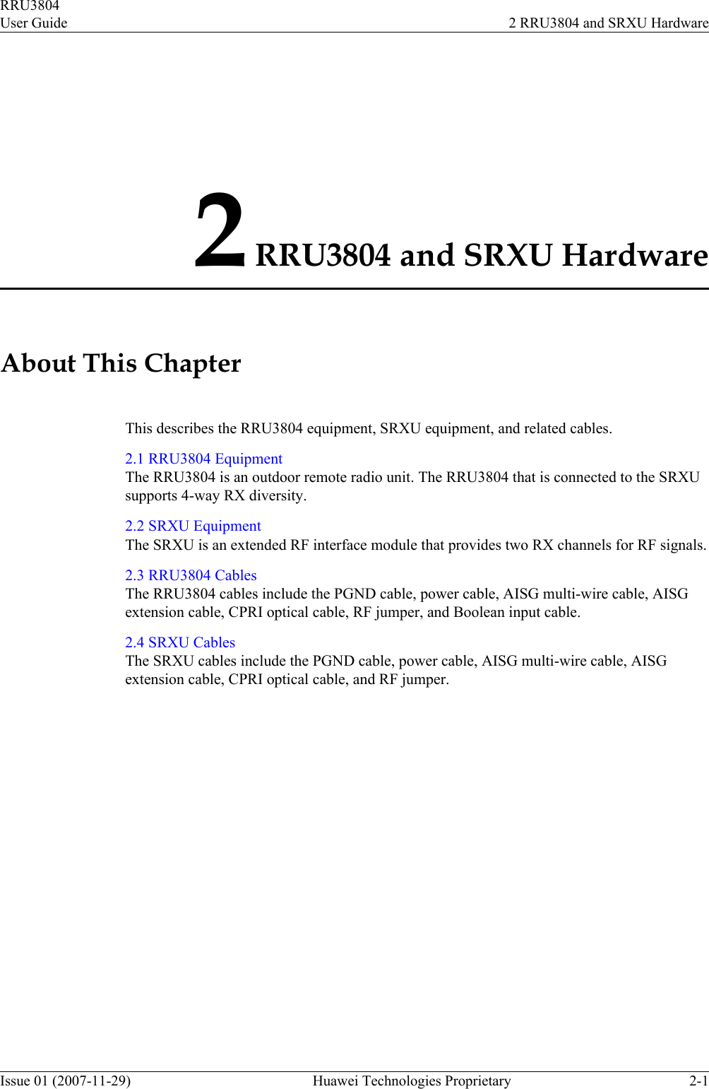
2.
User Manual 2
3.
User Manual 3
User Manual 1
Navigation menu
Upload a User Manual
Namespaces
Wiki Guide
HTML
PDF
Info
Views
User Manual
Discussion / Help
Navigation
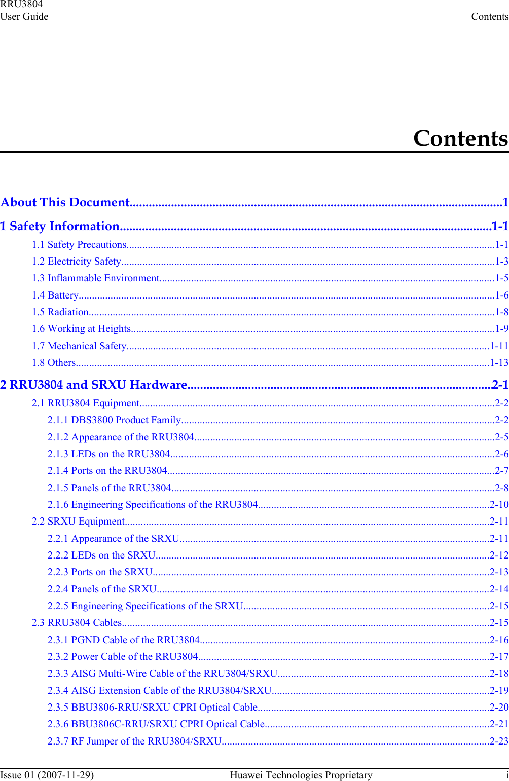
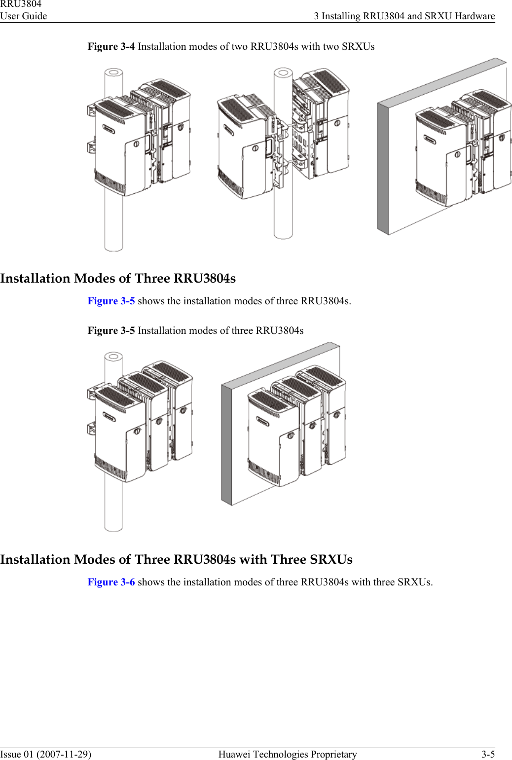
![After the RRU3804 and SRXU are deployed, accepted, and put into use, routine maintenanceis performed to ensure the functionality of the modules.Conventions1. Symbol ConventionsThe following symbols may be found in this document. They are defined as followsSymbol DescriptionDANGERIndicates a hazard with a high level of risk that, if not avoided,will result in death or serious injury.WARNINGIndicates a hazard with a medium or low level of risk which, ifnot avoided, could result in minor or moderate injury.CAUTIONIndicates a potentially hazardous situation that, if not avoided,could cause equipment damage, data loss, and performancedegradation, or unexpected results.TIP Indicates a tip that may help you solve a problem or save yourtime.NOTE Provides additional information to emphasize or supplementimportant points of the main text.2. General ConventionsConvention DescriptionTimes New Roman Normal paragraphs are in Times New Roman.Boldface Names of files,directories,folders,and users are in boldface. Forexample,log in as user root .Italic Book titles are in italics.Courier New Terminal display is in Courier New.3. Command ConventionsConvention DescriptionBoldface The keywords of a command line are in boldface.Italic Command arguments are in italic.[ ] Items (keywords or arguments) in square brackets [ ] are optional.About This DocumentRRU3804User Guide2 Huawei Technologies Proprietary Issue 01 (2007-11-29)](https://usermanual.wiki/Huawei-Technologies/RRU3804B4.User-Manual-1/User-Guide-1168075-Page-14.png)
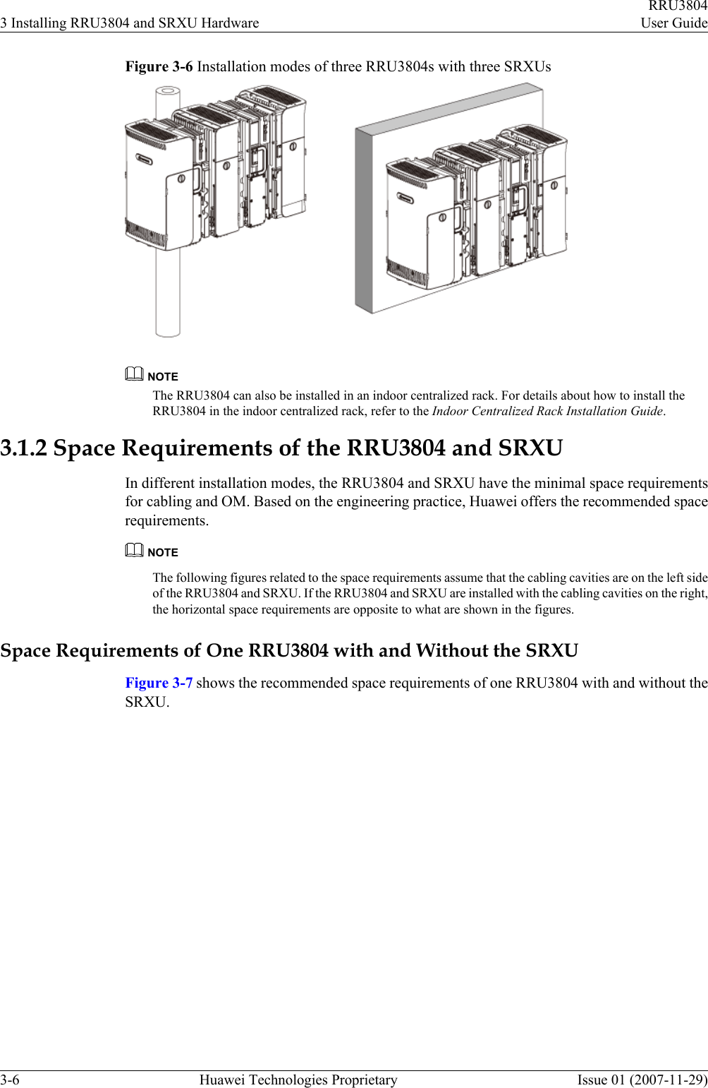
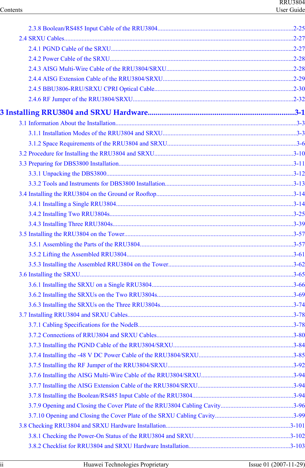
![Convention Description{x | y | ...} Alternative items are grouped in braces and separated by verticalbars.One is selected.[ x | y | ... ] Optional alternative items are grouped in square brackets andseparated by vertical bars.One or none is selected.{ x | y | ... } * Alternative items are grouped in braces and separated by verticalbars.A minimum of one or a maximum of all can be selected.[ x | y | ... ] * Alternative items are grouped in braces and separated by verticalbars.A minimum of zero or a maximum of all can be selected.4. GUI ConventionsConvention DescriptionBoldface Buttons,menus,parameters,tabs,window,and dialog titles are inboldface. For example,click OK.>Multi-level menus are in boldface and separated by the ">" signs.For example,choose File > Create > Folder .5. Keyboard OperationConvention DescriptionKey Press the key.For example,press Enter and press Tab.Key1+Key2 Press the keys concurrently.For example,pressing Ctrl+Alt+Ameans the three keys should be pressed concurrently.Key1,Key2 Press the keys in turn.For example,pressing Alt,A means the twokeys should be pressed in turn.6. Mouse OperationAction DescriptionClick Select and release the primary mouse button without moving thepointer.Double-click Press the primary mouse button twice continuously and quicklywithout moving the pointer.Drag Press and hold the primary mouse button and move the pointerto a certain position.RRU3804User Guide About This DocumentIssue 01 (2007-11-29) Huawei Technologies Proprietary 3](https://usermanual.wiki/Huawei-Technologies/RRU3804B4.User-Manual-1/User-Guide-1168075-Page-15.png)