Huawei Technologies RRU3804B4 Distributed NodeB Remote Radio Unit User Manual User Guide
Huawei Technologies Co.,Ltd Distributed NodeB Remote Radio Unit User Guide
UserManual.wiki
>
Huawei Technologies
>
RRU3804B4 User Manual
>
User Manual 3
Contents
1.
User Manual 1
2.
User Manual 2
3.
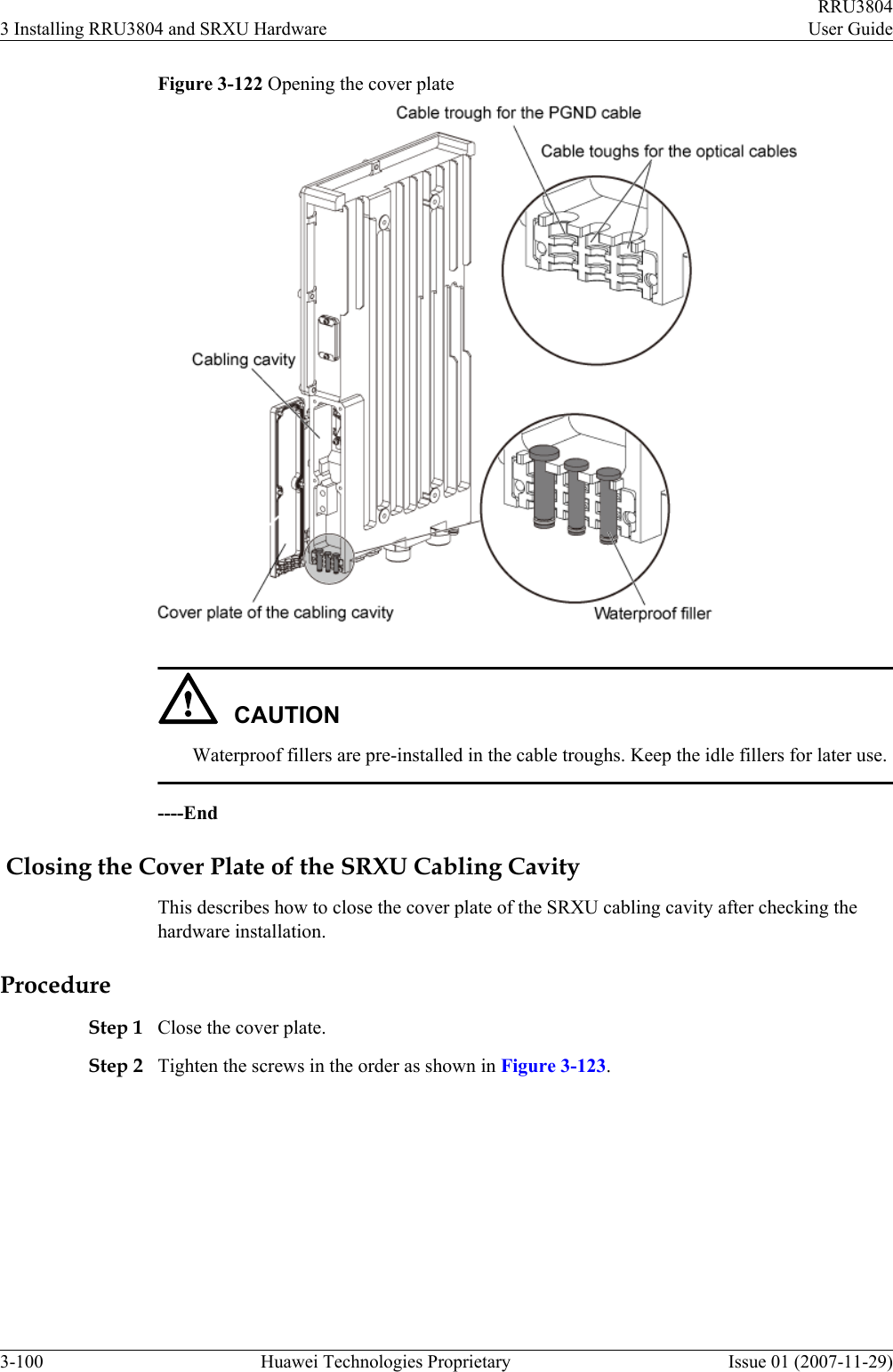
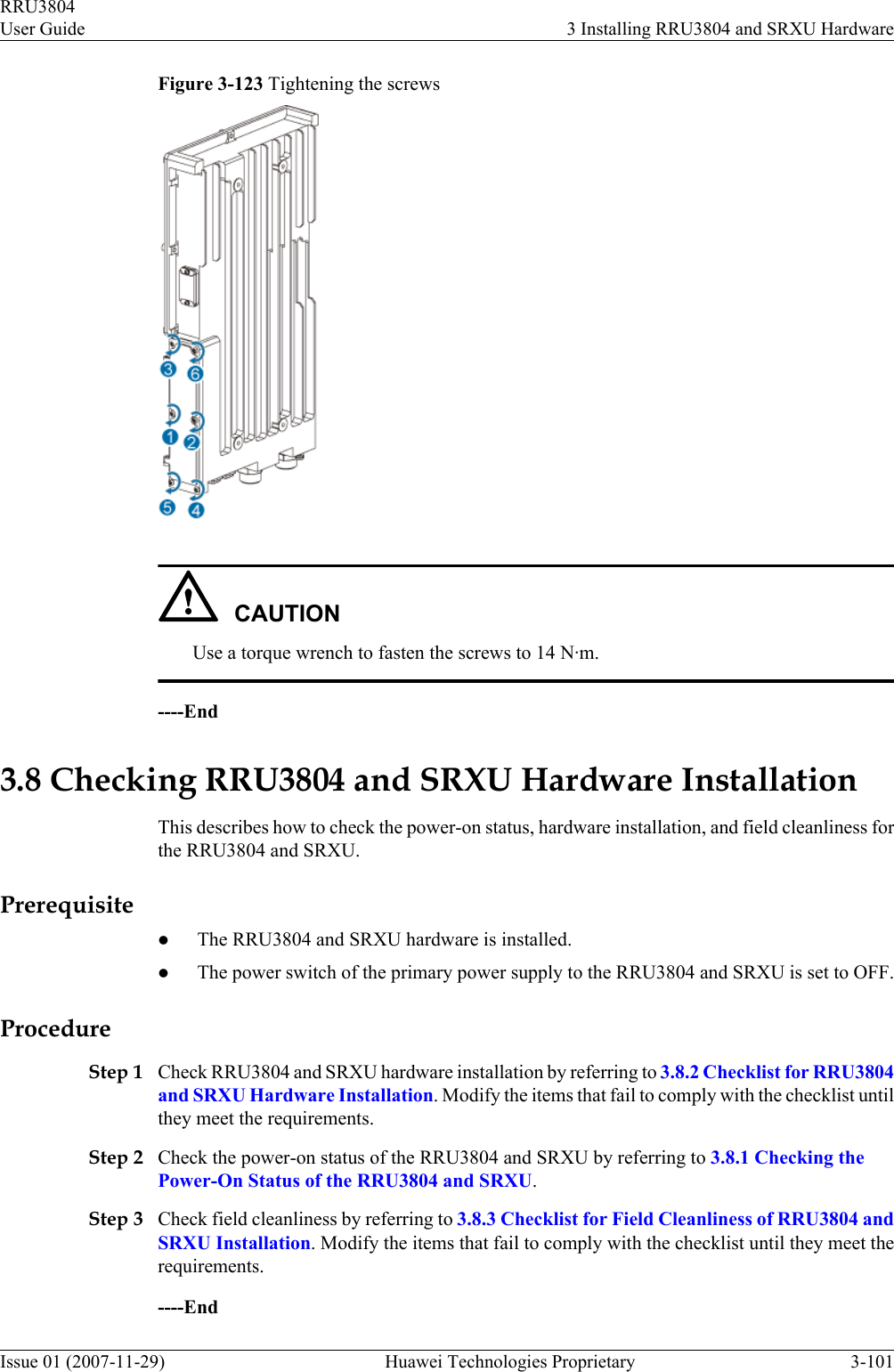
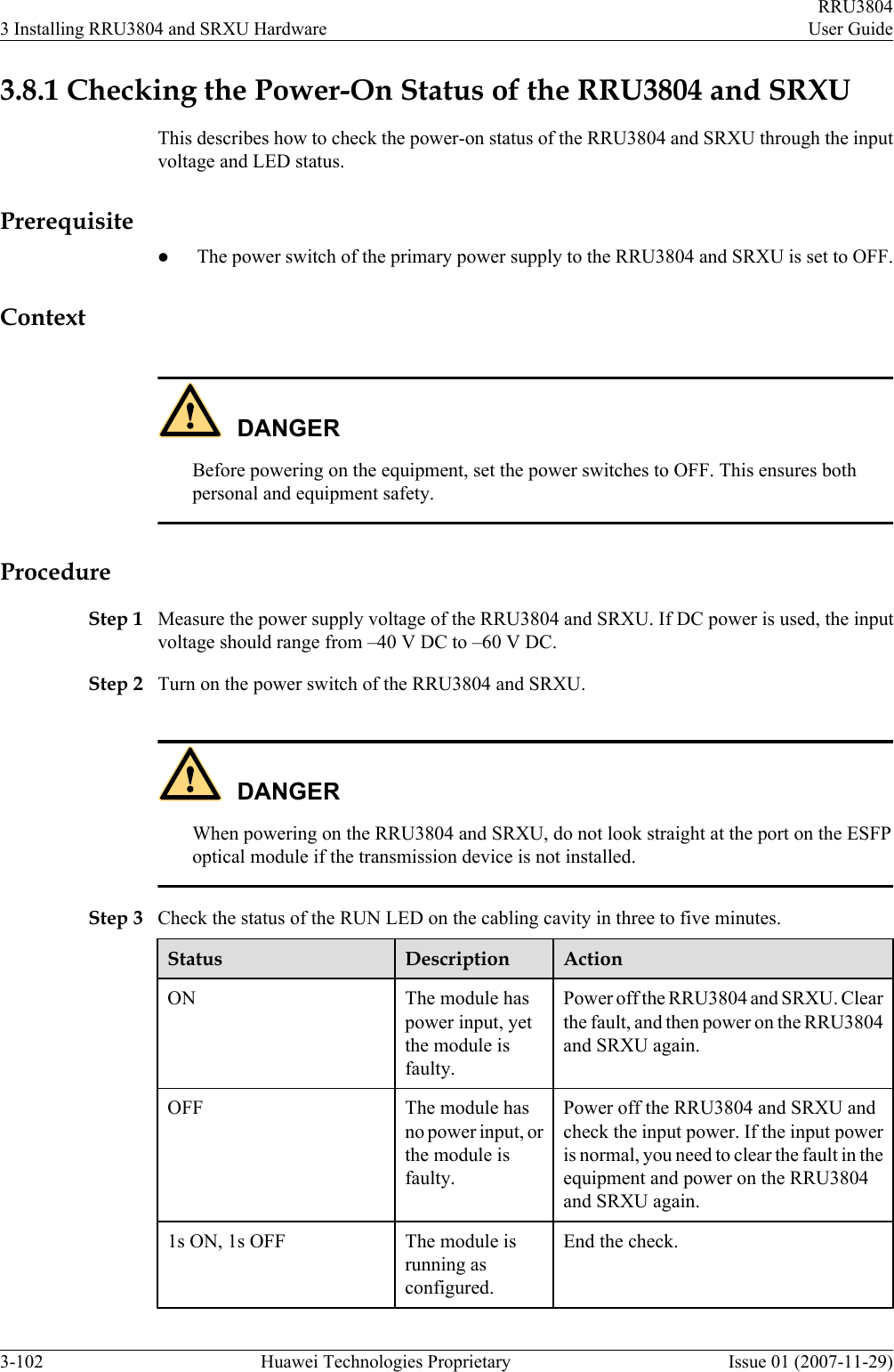
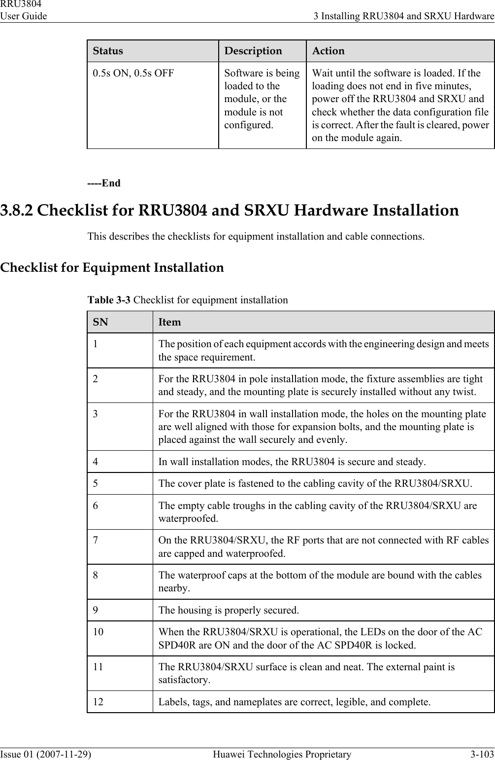
User Manual 3
User Manual 3
Navigation menu
Upload a User Manual
Namespaces
Wiki Guide
HTML
PDF
Info
Views
User Manual
Discussion / Help
Navigation