Huawei Technologies RTN360R6 Radio Transmission System User Manual 1
Huawei Technologies Co.,Ltd Radio Transmission System 1
Contents
- 1. Users Manual
- 2. Compliance and Safety Manual
- 3. Quick Installation Guide
- 4. Regulatory Compliance Statement
Quick Installation Guide

01
RTN 360 V100
Quick Installation Guide
Date: 2014-02-15
Huawei Technologies Co., Ltd.
Address: Huawei Industrial Base
Bantian, Longgang
Shenzhen 518129
People's Republic of China
Website: http://www.huawei.com
Email: support@huawei.com
No part of this document may be reproduced or transmitted in any form or by any means without prior
written consent of Huawei Technologies Co., Ltd.
Copyright © Huawei Technologies Co., Ltd. 2014. All rights reserved.
02/03 >>
Safety Precautions
Thunderstorms
Do not work with electrical current or work in elevated or exposed locations during a thunderstorm.
Extreme weather conditions
RTN 360 is usually installed outdoors. If weather conditions are extreme during an installation,
personnel should follow the related local guidelines and regulations to safeguard personal health
and safety.
Microwave
High-power radio frequency signals are harmful. Avoid exposure to transmission from the antennas of
microwave equipment that has the radiation warning symbol ( ). When you are installing or
performing maintenance on an antenna located on a tower that has multiple antennas, avoid exposure
to radiation from other antennas.
Elevated locations
RTN 360 is usually installed in an elevated location, for example, on the rooftop of a building. For installation
in elevated locations, installation personnel must:
• Have the proper training and qualifications, and meet health requirements.
• Wear helmets, safety belts, and anti-slip footwear.
• Wear clothing and gloves appropriate to weather conditions.
• Work in teams of two or more.
• Test hoisting tools before use.
• Avoid installation during extreme weather conditions, such as during thunderstorms, blizzards, or gales.
In addition, all site visitors must wear helmets.
High temperature
If the ambient temperature reaches 55°C, the surface temperature of an RTN 360 may exceed 70°C.
Therefore, wear protective gloves when handling the RTN 360. A high-temperature warning label
( ) is attached to each RTN 360.
Corrosion
Anti-corrosion measures are required if an RTN 360 is installed in a location that is prone to corrosion. Contact the
local Huawei office for details. A location is prone to corrosion if it is:
•Within 3.7 km of an ocean or a salt water lake
•Within 3 km of a heavy pollution source, such as a smelting factory or coal mine
•Within 2 km of a medium pollution source, such as a chemical, rubber, or electroplating plant
•Within 1 km of a light pollution source, such as a food/leather processing plant or heating boiler
Port protection
•Fasten PG covers onto the network ports of an RTN
360, and protect unused ports with caps.
•Retain removed caps for future use.
Caps
Unpacking
•After unpacking an RTN 360, power it on within 24 hours.
•Do not power off an RTN 360 for more than 24 hours during maintenance.
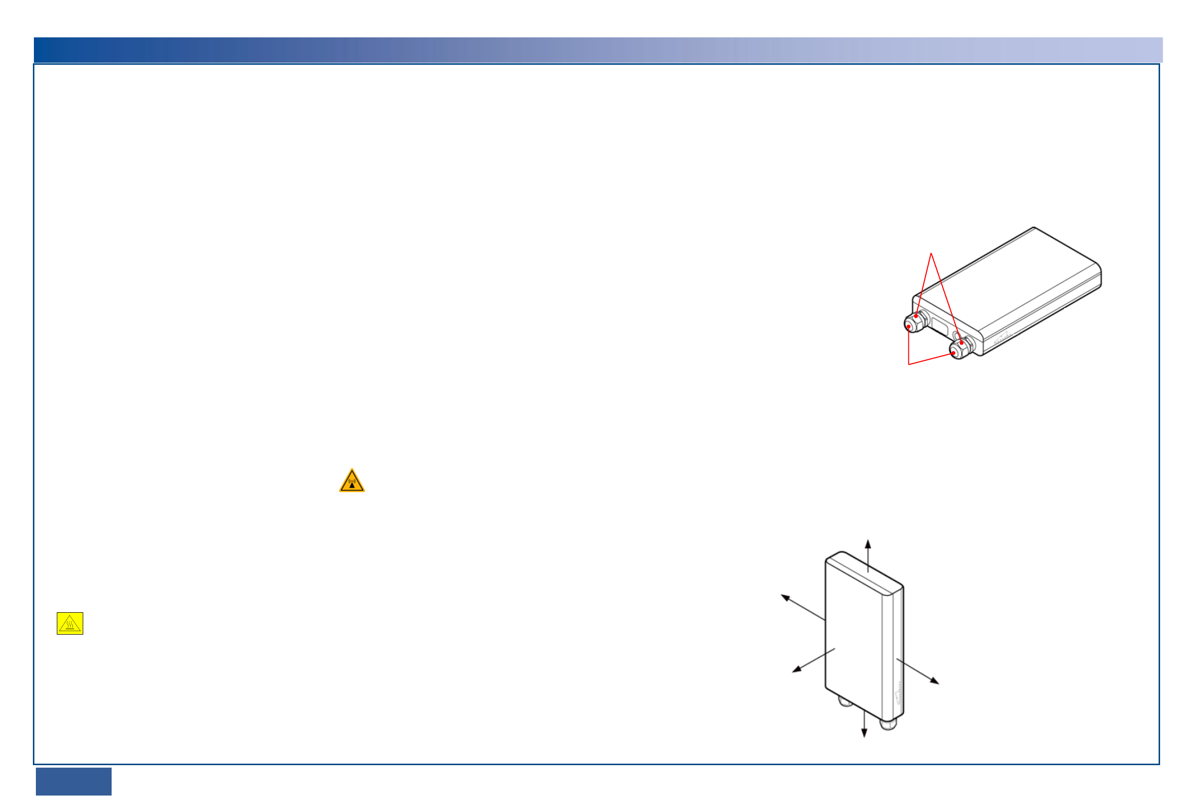
Minimal installation space
The following figure illustrates the minimal installation space required for an RTN 360.
≥ 300 mm
≥ 300 mm
≥ 500 mm
≥ 500 mm
Ensure that the signal
transmission path leading
from the front of an RTN 360
to its peer is unobstructed.
Handling of RTN 360 or mounting kits
Wear clean gloves when handling the RTN 360 or mounting kits.
PG covers
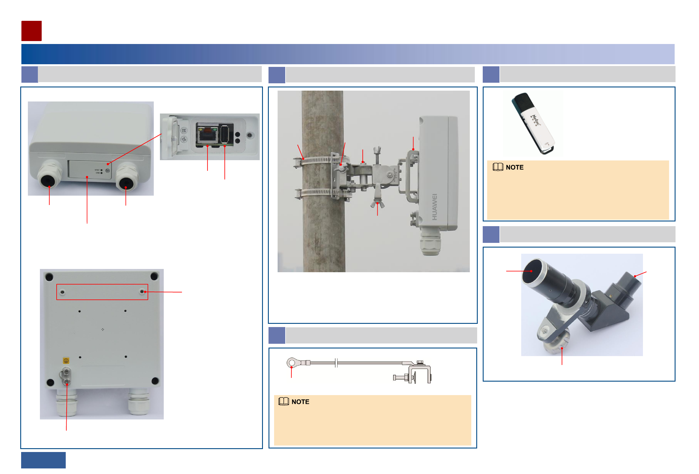
A Appearance and ports
Equipment Components
Installing an RTN 360
04/05 >>
Port P&E (receiving both
services and power
signals)
Port GE(e)
B Mounting kits
1. Attachment plate (installed before delivery)
2. Hose clamp (used when an RTN 360 is installed on a pole)
3. Azimuth adjustment nut
4. Fastener (with holes used for installing an RTN 360 on a wall or pole)
5. Elevation adjustment nut
Maintenance
compartment
RSSI/NMS port
USB port
Inside the maintenance compartment
Holes for mounting an
alignment scope
Ground screw
Front view
Rear view
D USB flash drive
•The recommended USB flash drive is a 4 GB Netac U208. If a
different model or capacity is required, contact the local Huawei
office. USB flash drives not meeting requirements may be
incompatible.
•The appearance of the shipped USB flash drive may differ from
that shown here.
E Alignment scope
Mounting frame
Lens Eyepiece
OT terminal
C Ground cable
•The ground terminal can connect to a ground bar or U-shaped ground
clip.
•For information about how to connect the ground terminal to a U-
shaped ground clip, see the usage description document supplied with
the clip.
Ground terminal
1
2 3
5
4
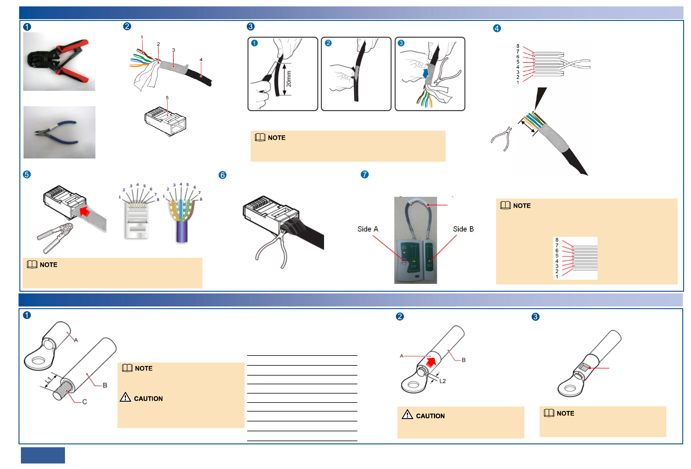
Terminating an Outdoor Network Cable with Shielded RJ45 Connectors
06/07 >>
Prepare the following tools.
RJ45 connector crimping tool
Diagonal pliers
Prepare an outdoor network cable
and shielded RJ45 connectors.
1. Core wire
2. Aluminum foil
3. Braid shield
4. Outer jacket
5. Shielded RJ45 connector
Strip the cable.
Length of the stripped
cable: 20 mm
Strip off the braid shield and cut
the aluminum foil and unwanted
materials.
When stripping off the outer jacket, take care not to damage the braid shield
or aluminum foil.
Remove the outer jacket.
Arrange the core wires according to the pin assignments and cut them
neatly (exposing a length of 12 mm).
12 mm
Cut the core wires neatly.
Length of each exposed core wire: 12 mm
8: brown
7: white and brown
6: green
5: white and blue
4: blue
3: white and green
2: orange
1: white and orange
Insert the arranged core wires into an RJ45 connector according to the pin
assignments and crimp the connector with the crimping tool.
Pin assignments of an RJ45 connector
Crimp the RJ45
connector.
Cut off the exposed braid shield and materials
along the edge of the connector.
Cut off the exposed braid
shield and materials.
Outdoor network
cable
Terminate a connector on the other end of the network cable, and then test the cable
for continuity using a network cable tester.
The pin assignments of the connectors at the two ends must be the same. Outdoor
network cables are straight-through cables.
Terminating a Ground Cable with an OT Terminal
Strip the ground cable.
A: OT terminal
B: ground cable
C: exposed cable conductor
L1: length of the exposed cable
When you are skillful, you can determine L1
based on the length of the OT terminal lug.
When striping off the insulation layer of the
ground cable, take care not to damage or nick
the metal conductor of the cable.
Before crimping, ensure that the core wires are fully inserted in the RJ45
connector.
Fit the exposed cable into the OT terminal.
Ensure that the cable conductor does not
protrude more than 2 mm from the OT terminal.
Crimp the OT terminal lug.
The impression left from crimping the lug may
differ depending on the crimping tool used.
Mapping between the cross-sectional area of a
cable conductor (C) and the length of an exposed
cable (L1)
Cross-sectional
Area of C (mm2) L1 (mm)
1
1.5
2.5
4
6
10
16
25
35
50
7
7
7
8
9
11
13
14
16
16
Crimp the OT
terminal lug.
Generally, straight-through cables are used with the RTN 360.
Crossover cables are required only when the BTS3902E and BTS3202E
supplies power over Ethernet to the RTN 360. In this case, the pin
assignments of the connector at the other end are as follows:
8: brown
7: white and brown
6: orange
5: white and blue
4: blue
3: white and orange
2: green
1: white and green
Installing an RTN 360
08/09 >>
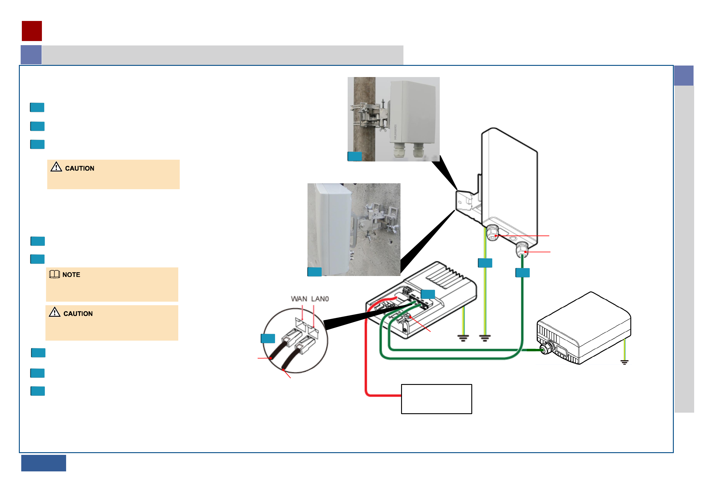
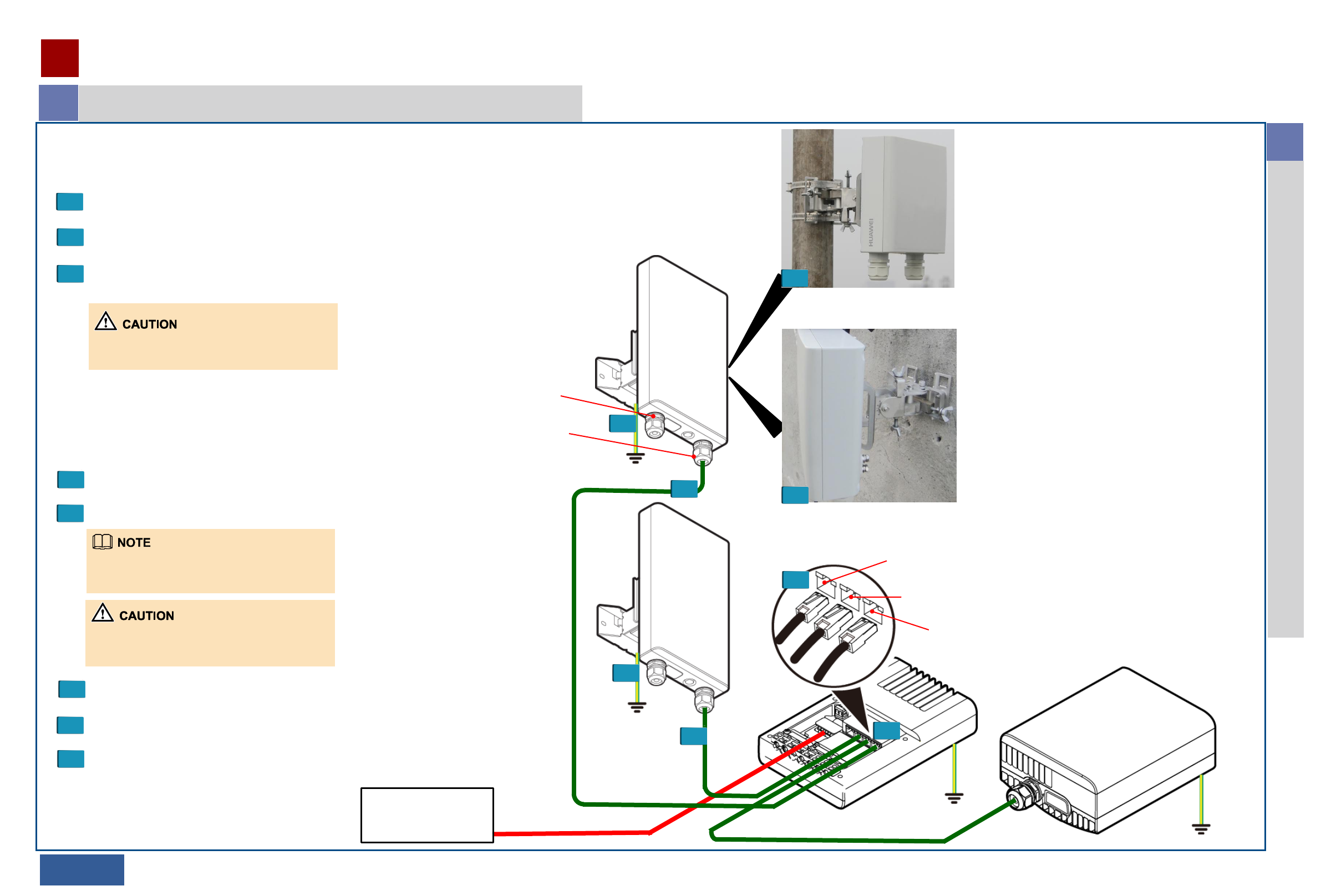
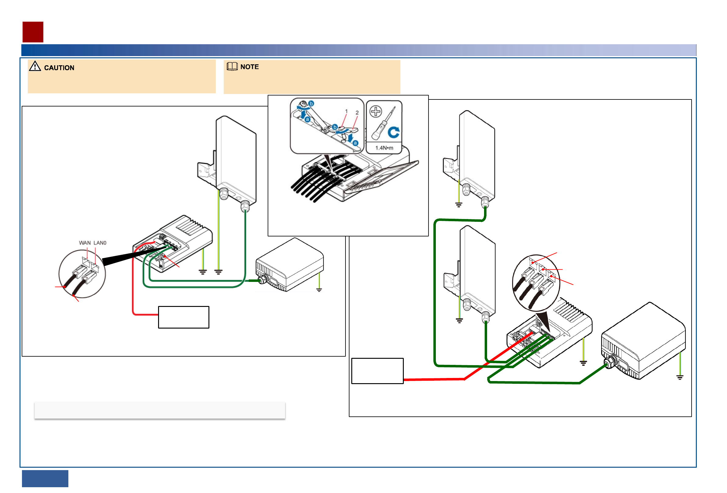
Installing an RTN 360 at the Edge of a Mobile Backhaul Network
1
1 Installing an RTN 360 at the Edge of a Mobile Backhaul Network
Optional: Install the
RTN 360 on a pole.
Optional: Install the
RTN 360 on a wall.
External power
supply equipment
In this example, the RTN 360 uses port
P&E to receive services and power
signals.
1
1
2
3
6
6
Installation procedure
1 Install an RTN 360 on a pole or wall.
2 Install the ground cable.
3 Connect one end of an outdoor network cable to port
P&E on the RTN 360.
5 Connect the other end of the outdoor network cable to port WAN on a Dock.
To the RTN 360
To the opposite wireless equipment
Traffic transmitted to the opposite wireless
equipment is forwarded by port LAN0 on the Dock.
Use clips to fix any indoor sections of the outdoor
network cables that connect to ports WAN and
LAN0 on the Dock. Clip
Commissioning procedure
6 Load commissioning data to the RTN 360 using the
Web LCT or USB flash drive.
Ensure that the received signal level (RSL) of
the RTN 360 meets the requirement.
7
8 Verify the installation.
PoE supports a maximum distance of 100 meters.
RTN 360
Dock
Optional: In this example, port GE(e) is
not used. In practice, determine whether
to use this port based on your service
plan.
Opposite wireless equipment
4 Align the RTN 360 with its peer.
Installing an RTN 360
10/11 >>
Installing RTN 360s at 2x(1+0) Aggregation Sites
2
2 Installing RTN 360s at 2x(1+0) Aggregation Sites
Port WAN, which is connected to one RTN 360
Port LAN0, which is connected to the opposite wireless equipment
Port LAN1, which is connected to the other RTN 360
Optional: Install the
RTN 360 on a wall.
1
Optional: Install the
RTN 360 on a pole.
1
RTN 360
RTN 360
Dock
Opposite wireless equipment
External power
supply equipment
2
2
3
3 6
6
Installation procedure
1 Install two RTN 360s on a pole or wall.
2 Install their respective ground cables.
3 Connect an outdoor network cable to port P&E on each
RTN 360.
5 Connect one of the two outdoor network cables to port WAN on
a Dock and the other to port LAN1 on the Dock.
Traffic transmitted to the opposite wireless
equipment is forwarded by port LAN0 on the Dock.
Use clips to fix any indoor sections of the outdoor
network cables that connect to ports WAN, LAN0,
and LAN1 on the Dock.
Commissioning procedure
6 Load commissioning data to the RTN 360s using
the Web LCT or USB flash drive.
Ensure that the RSLs of the two RTN 360s meet
the requirements.
7
8 Verify the installation.
PoE supports a maximum distance of 100 meters.
4 Align each RTN 360 with its peer.
In this example, both RTN 360s use
their respective P&E ports to receive
services and power signals.
Optional: In this example, port GE(e)
on neither RTN 360 is used. In practice,
determine whether to use this port
based on your service plan.
Unscrew the azimuth
adjustment nut.
Hook the RTN 360 box (with the attachment plate
installed) to the fastener along the dowel.
Tighten the azimuth
adjustment nut using a hex key.
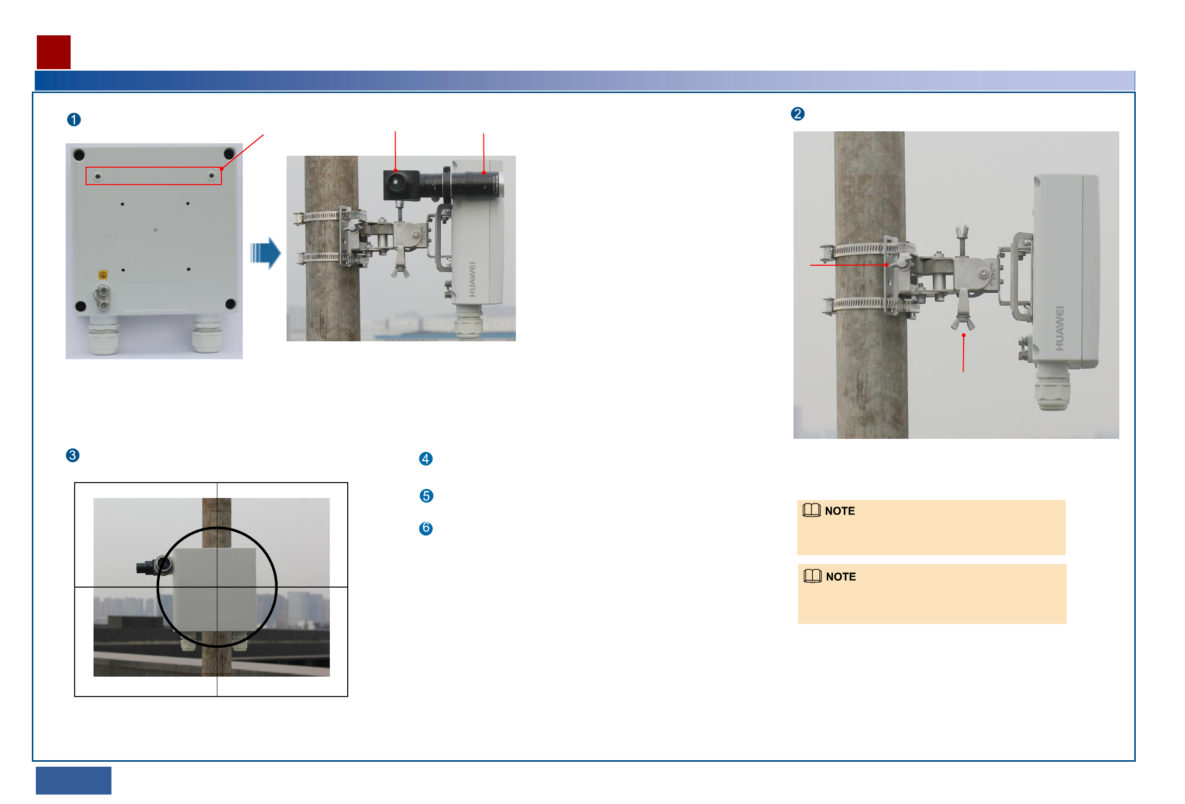
References for Installation
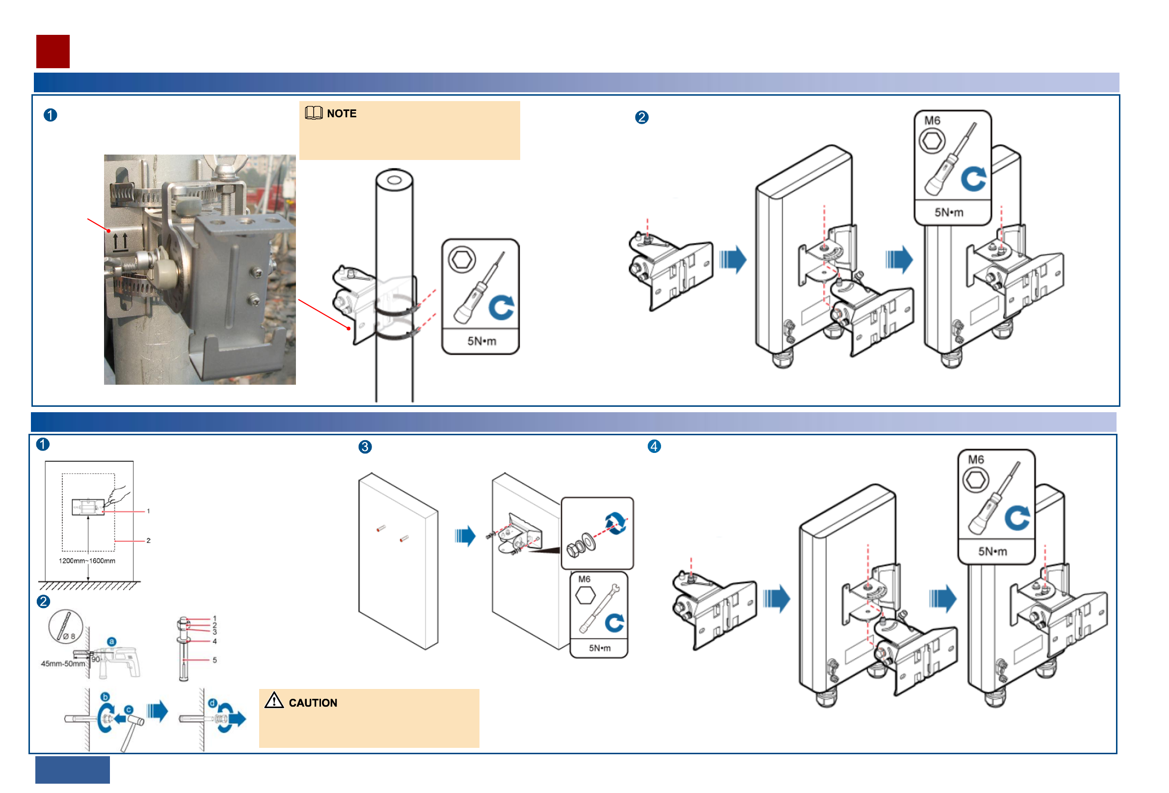
Optional: Installing an RTN 360 on a Pole
12/13 >>
Pass the hose clamps through the fastener and fix the hose
clamps on a pole using the screws of the hose clamps. Install the RTN 360 box securely on the fastener.
Unscrew the azimuth
adjustment nut.
Hook the RTN 360 box (with the attachment plate
installed) to the fastener along the dowel. Tighten the azimuth
adjustment nut using a hex key.
Optional: Installing an RTN 360 on a Wall
Press the fastener against a wall, level the installation location
using a level, and mark locating points using a marker.
Drill holes and install expansion bolts at the locating points.
Install the fastener onto the expansion bolts, place a flat washer, a
spring washer, and a nut on each expansion bolt, and then tighten
the nuts.
Ensure that each expansion bolt protrudes from 8
mm to 12 mm.
1. M6x60 bolt
2. Nut
3. Spring washer
4. Flat washer
5. Expansion sleeve
1. Fastener
2. RTN 360
Install the RTN 360 box securely on the fastener.
This side up
Before fixing the hose clamps, ensure that the
azimuth faces the peer site.
References for Installation
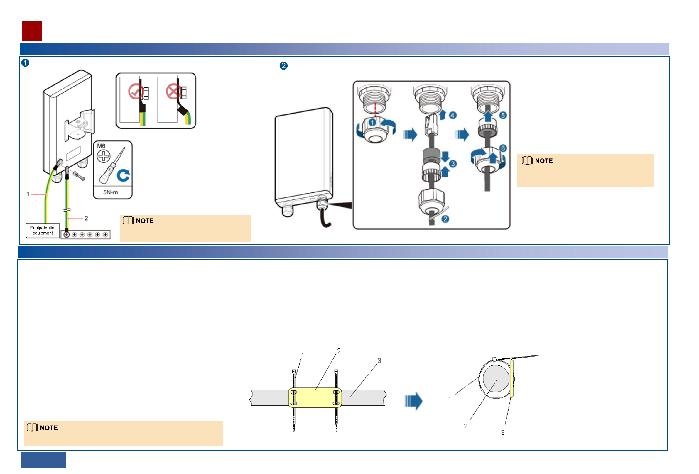
Installing Cables
14/15 >>
Laying out Cables
Install a ground cable.
1. Optional: Connect the ground cable to equipotential equipment.
2. Optional: Connect the ground cable to a ground bar.
Install an outdoor network cable.
Ensure that the OT terminal of the
ground cable is correctly installed.
After installing the ground cable, apply antirust paint
to the ground bar or point.
1. Unscrew the PG cover installed on port P&E of the RTN 360
using a 1.8 N•m torque wrench (rotating the wrench
counterclockwise).
2. Attach a cable tie to the network cable to prevent the PG
cover from sliding down.
3/4. Route the network cable through the PG cover and
connect the cable to port P&E of the RTN 360.
5/6. Insert the plug of the network cable into port P&E and
screw the PG cover.
The procedure for installing an outdoor network cable
on port GE(e) of an RTN 360 is the same as the
procedure described here.
1. Bend radius
For power and PGND cables, ensure a bend radius of at least three times the
cable diameter.
2. Cable binding
•Bind different cables separately, with a minimum distance of 30 mm.
•Bind cables securely and neatly, without damaging the cable jackets.
•Ensure that cable ties face the same direction and are aligned in rows horizontally.
•Cut off the excess of each indoor cable tie but leave a slack of about 5 mm for
each outdoor cable tie. Ensure that all cut surfaces do not have sharp edges.
•After installing cables, attach labels or tags to the two ends of each cable.
3. Safety
•Lay out cables away from sharp objects or jagged walls, or protect cables using
conduit.
•Lay out cables away from heat sources, or add heat-insulation materials between
cables and heat sources.
•At turns or near equipment, allow sufficient slack in the cables and coil them (with
a diameter of about 0.6 meters) for future use.
4. Indoor cable routing
•Route cables into equipment rooms through feeder windows.
•Form drip loops outside feeder windows and ensure a bend radius equal to or
greater than the required minimum bend radius.
•Seek help indoors when routing cables into equipment rooms.
•Waterproof feeder windows.
General requirements
The requirements for indoor cable routing apply if any section of cable will be
routed indoors.
Requirements for laying out cables outdoors
Route cables along the planned path, use outdoor cable ties to bind cables properly
and neatly at intervals of about 1 meter, and cut off the excess of each cable tie
without leaving sharp edges (ensuring a slack of about 5 mm).
Requirements for laying out PGND cables
•Connect PGND cables of co-sited devices to the same ground bar.
•Do not route PGND cables overhead in outdoor scenarios.
•Bind PGND cables separately from outdoor network cables and keep a
certain distance between the bundles.
•Do not add switches or fuses on PGND cables.
Installing sign plate labels
Attach a sign plate label to each cable end. To do so, pass cable
ties through the holes in the label and attach it to one cable end,
about 100 mm to 200 mm away from the connector.
Tighten the cable ties to fix the label on the cable. Then, cut off the excess
of each cable tie, leaving a slack of about 5 mm and no sharp edges.
1. Outdoor cable tie
2. Sign plate label
3. Cable
References for Installation
16/17 >>
Aligning an RTN 360
Install the alignment scope.
1
Adjust the azimuth and elevation of the RTN 360 by rotating the azimuth and
elevation adjustment nuts.
.
2
By rotating the elevation adjustment nut (nut
2), you can adjust the elevation of the RTN
360 from -50° to +50°.
By rotating azimuth
adjustment nut (nut 1),
you can adjust the
azimuth of the RTN
360 from -50° to
+50°.
Holes for installing
the alignment scope
Eyepiece Lens
Adjust the azimuth and elevation of the local RTN 360 slowly to
move the crosshair of the alignment scope to the peer RTN 360. Tighten the azimuth and elevation adjustment nuts.
Align the peer RTN 360 with the local RTN 360 in the
same way.
Remove the alignment scope.
Peer site
To adjust the azimuth and elevation of an RTN 360, rotate the
azimuth and elevation adjustment nuts. Do not attempt to turn
the device or mounting kits.
If the azimuth adjustment is insufficient to align the RTN 360
with its peer, loosen the hose clamp, re-position the RTN 360,
and then fasten the hose clamp.
External power
supply equipment
To the
RTN 360
To the opposite
wireless equipment
Clip
RTN 360
Dock
Opposite wireless equipment
Port WAN, which is connected to one RTN 360
Port LAN0, which is connected to the
opposite wireless equipment
Port LAN1, which is connected to the
other RTN 360
RTN 360
RTN 360
Dock
Opposite wireless equipment
External power
supply equipment
References for Installation
18/19 >>
Powering On an RTN 360
•After unpacking an RTN 360, power it on within 24 hours.
•Do not power off an RTN 360 for more than 24 hours during maintenance.
•Ensure that the Dock is powered on and works properly.
•On an RTN 360, only port P&E supports power over Ethernet.
If one Dock supplies power to only one RTN 360, connect the outdoor network cable that
connects to port P&E on the RTN 360 to port WAN on the Dock.
If one Dock supplies power to two RTN 360s, connect the outdoor network cable that connects to
port P&E on one RTN 360 to port WAN on the Dock, and the outdoor network cable that
connects to port P&E on the other RTN 360 to port LAN1 on the Dock.
STAT: is steady green.
When an RTN 360 is running properly, its indicators should be in the following states:
Use clips to fix any indoor sections of the outdoor network
cables that connect to ports WAN, LAN0, and LAN1 on the
Dock, and remove the plugs in the cable trough.
References for Installation
20/21 >>
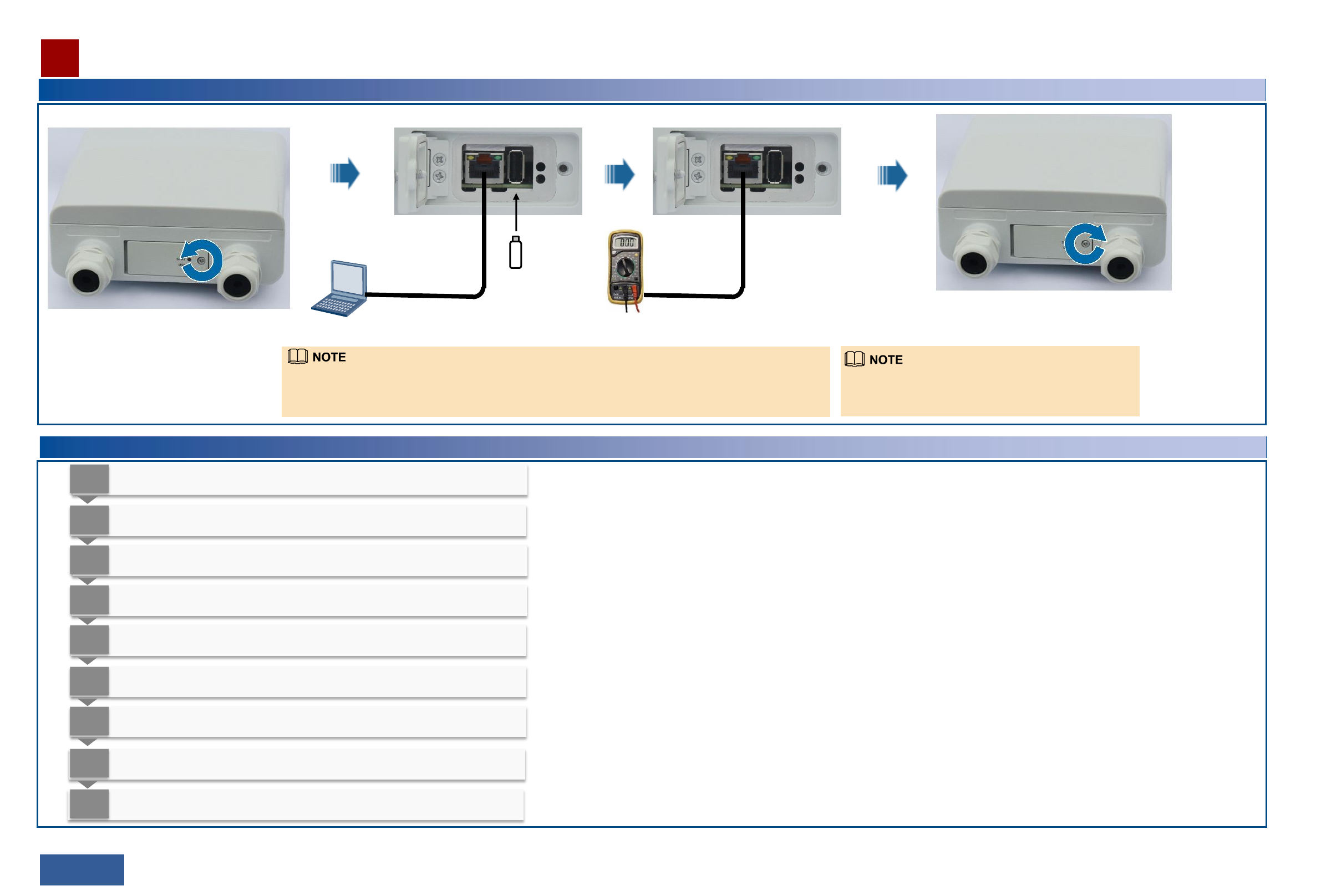
Loading Configuration Data and Measuring the RSL
USB flash drive
Web LCT
Open the maintenance compartment.
Load configuration data.
Close the maintenance compartment.
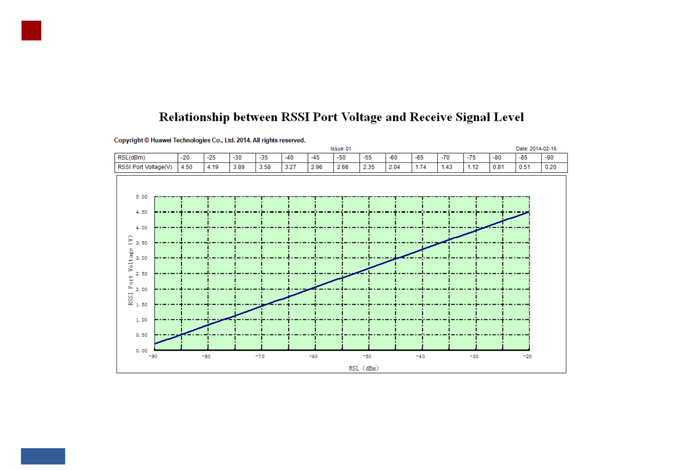
RSL tester
Measure the RSL.
If the RSL is lower than the required value, re-align the
RTN 360 pair.
Verifying the Installation
1
Verify that RTN 360s are installed in planned locations and sufficient space is reserved
for maintenance.
2
Verify that RTN 360s are securely installed by turning the boxes gently (in both the
horizontal and vertical directions).
3
Verify that OT terminals of PGND cables are tightly crimped and PGND cables are not
damaged or broken.
4
Verify that PGND cables are bound separately from other cables.
5
Verify that the protection ground of an RTN 360 shares the same ground bar with the
lightning protection ground of the building bearing the RTN 360.
6
Verify that shielded RJ45 connectors of outdoor network cables are intact and tightly
crimped and the cables are not damaged or broken.
7
Verify that PG covers are tightly screwed onto the network ports of RTN 360s, unused
ports are protected with caps, and removed caps are retained for future use.
8
Verify that outdoor network cables are routed along planned paths and bound properly
and neatly at equal intervals (about 1 meter), and the excess of each cable tie is cut off
without leaving sharp edges.
9 Verify that alignment scopes are removed and kept secure.
If a Wi-Fi module is installed at the USB port, you can determine whether the Wi-Fi module is working properly
by enabling it to search for the SSID of an NE in the wireless LAN. If the SSID can be searched out, the Wi-Fi
module is working properly. If the SSID cannot be searched out, open the maintenance compartment and view
the Wi-Fi module indicator. If the indicator is steady red, replace the Wi-Fi module.
References for Installation
22/23 >>