Huawei Technologies RTN360R6 Radio Transmission System User Manual Product Description
Huawei Technologies Co.,Ltd Radio Transmission System Product Description
Contents
Users Manual

OptiX RTN 360 Radio Transmission System
V100R006C00
Product Description
Issue 01
Date 2016-01-15
HUAWEI TECHNOLOGIES CO., LTD.

Copyright © Huawei Technologies Co., Ltd. 2016. All rights reserved.
No part of this document may be reproduced or transmitted in any form or by any means without prior written
consent of Huawei Technologies Co., Ltd.
Trademarks and Permissions
and other Huawei trademarks are trademarks of Huawei Technologies Co., Ltd.
All other trademarks and trade names mentioned in this document are the property of their respective
holders.
Notice
The purchased products, services and features are stipulated by the contract made between Huawei and the
customer. All or part of the products, services and features described in this document may not be within the
purchase scope or the usage scope. Unless otherwise specified in the contract, all statements, information,
and recommendations in this document are provided "AS IS" without warranties, guarantees or
representations of any kind, either express or implied.
The information in this document is subject to change without notice. Every effort has been made in the
preparation of this document to ensure accuracy of the contents, but all statements, information, and
recommendations in this document do not constitute a warranty of any kind, express or implied.
Huawei Technologies Co., Ltd.
Address: Huawei Industrial Base
Bantian, Longgang
Shenzhen 518129
People's Republic of China
Website: http://www.huawei.com
Email: support@huawei.com
Issue 01 (2016-01-15) Huawei Proprietary and Confidential
Copyright © Huawei Technologies Co., Ltd.
i

About This Document
Related Versions
The following table lists the product versions related to this document.
Product Name Version
OptiX RTN 360 V100R006C00
iManager U2000–T V200R015C60
iManager U2000–M V200R015C10
Intended Audience
This document is intended for:
lNetwork planning engineer
lHardware installation engineer
lInstallation and commissioning engineer
lField maintenance engineer
lData configuration engineer
lSystem maintenance engineer
Familiarity with the basic knowledge related to digital microwave communication technology
will help you apply the information in this document.
Symbol Conventions
The symbols that may be found in this document are defined as follows.
Symbol Description
Indicates an imminently hazardous situation
which, if not avoided, will result in death or
serious injury.
OptiX RTN 360 Radio Transmission System
Product Description About This Document
Issue 01 (2016-01-15) Huawei Proprietary and Confidential
Copyright © Huawei Technologies Co., Ltd.
ii

Symbol Description
Indicates a potentially hazardous situation
which, if not avoided, could result in death
or serious injury.
Indicates a potentially hazardous situation
which, if not avoided, may result in minor
or moderate injury.
Indicates a potentially hazardous situation
which, if not avoided, could result in
equipment damage, data loss, performance
deterioration, or unanticipated results.
NOTICE is used to address practices not
related to personal injury.
Calls attention to important information,
best practices and tips.
NOTE is used to address information not
related to personal injury, equipment
damage, and environment deterioration.
General Conventions
The general conventions that may be found in this document are defined as follows.
Convention Description
Times New Roman Normal paragraphs are in Times New Roman.
Boldface Names of files, directories, folders, and users are in
boldface. For example, log in as user root.
Italic Book titles are in italics.
Courier New Examples of information displayed on the screen are in
Courier New.
Change History
Changes between document issues are cumulative. The latest document issue contains all the
changes made in earlier issues.
Issue 01 (2016-01-15)
This issue is the first release for the product version V100R006C00.
OptiX RTN 360 Radio Transmission System
Product Description About This Document
Issue 01 (2016-01-15) Huawei Proprietary and Confidential
Copyright © Huawei Technologies Co., Ltd.
iii

Contents
About This Document.....................................................................................................................ii
1 Product Introduction.....................................................................................................................1
1.1 Network Application...................................................................................................................................................... 2
1.2 Product Specifications.................................................................................................................................................... 3
1.3 Site Configurations......................................................................................................................................................... 4
1.3.1 Sites Providing One-Direction Microwave Links....................................................................................................... 4
1.3.2 Sites Providing Two-Direction Microwave Links.......................................................................................................5
1.3.3 Sites Providing Multi-direction Microwave Links......................................................................................................6
2 Functions and Features.................................................................................................................8
2.1 Integration.....................................................................................................................................................................10
2.2 TDD.............................................................................................................................................................................. 10
2.3 Automatic Frequency Selection....................................................................................................................................11
2.4 Adaptive Modulation....................................................................................................................................................12
2.5 Power over Ethernet..................................................................................................................................................... 14
2.6 Ethernet Service Processing Capability........................................................................................................................15
2.7 QoS............................................................................................................................................................................... 17
2.8 Clock Features.............................................................................................................................................................. 19
2.9 Network Management.................................................................................................................................................. 20
2.10 Rapid Deployment......................................................................................................................................................21
2.11 Easy Maintenance....................................................................................................................................................... 22
2.11.1 Contact-Free Maintenance.......................................................................................................................................22
2.11.2 Equipment-Level OAM........................................................................................................................................... 23
2.11.3 Packet OAM (TP-Assist)......................................................................................................................................... 25
2.12 Security Management................................................................................................................................................. 27
2.13 Energy Saving.............................................................................................................................................................30
2.14 Environmental Protection........................................................................................................................................... 30
3 Product Structure......................................................................................................................... 31
3.1 System Architecture..................................................................................................................................................... 32
3.2 Service Signal Processing Flow................................................................................................................................... 34
3.3 Ports.............................................................................................................................................................................. 36
3.4 Indicators...................................................................................................................................................................... 41
3.5 Labels............................................................................................................................................................................43
OptiX RTN 360 Radio Transmission System
Product Description Contents
Issue 01 (2016-01-15) Huawei Proprietary and Confidential
Copyright © Huawei Technologies Co., Ltd.
iv

4 Network Management System..................................................................................................46
4.1 Network Management Solutions.................................................................................................................................. 47
4.2 Web LCT...................................................................................................................................................................... 48
4.3 Mobile LCT.................................................................................................................................................................. 48
4.4 U2000-T........................................................................................................................................................................49
4.5 U2000-M...................................................................................................................................................................... 51
5 Technical Specifications.............................................................................................................52
5.1 Ethernet Service Specifications.................................................................................................................................... 53
5.2 RF Performance............................................................................................................................................................54
5.3 Antenna Performance................................................................................................................................................... 55
5.4 Predicted Reliability..................................................................................................................................................... 55
5.5 Integrated System Performance....................................................................................................................................56
6 Accessories.................................................................................................................................... 58
6.1 Power Injector...............................................................................................................................................................59
6.2 USB Flash Drives......................................................................................................................................................... 59
6.3 Wi-Fi Module............................................................................................................................................................... 62
7 Cables.............................................................................................................................................64
7.1 Outdoor Network Cables.............................................................................................................................................. 65
7.2 Outdoor Optical Fiber...................................................................................................................................................66
7.3 RSSI Cables..................................................................................................................................................................67
7.4 RTN 360 PGND Cables................................................................................................................................................68
A Appendix......................................................................................................................................69
A.1 Port Loopbacks............................................................................................................................................................ 70
A.2 Component Photos.......................................................................................................................................................70
A.3 Compliance Standards................................................................................................................................................. 71
A.3.1 ITU-R Standards.......................................................................................................................................................71
A.3.2 ITU-T Standards....................................................................................................................................................... 73
A.3.3 ETSI Standards......................................................................................................................................................... 74
A.3.4 CEPT Standards........................................................................................................................................................76
A.3.5 IEC Standards........................................................................................................................................................... 77
A.3.6 IETF Standards......................................................................................................................................................... 78
A.3.7 IEEE Standards.........................................................................................................................................................79
A.3.8 Other Standards........................................................................................................................................................ 80
OptiX RTN 360 Radio Transmission System
Product Description Contents
Issue 01 (2016-01-15) Huawei Proprietary and Confidential
Copyright © Huawei Technologies Co., Ltd.
v

1 Product Introduction
About This Chapter
The OptiX RTN 360 radio transmission system (RTN 360 for short) is a full-outdoor radio
transmission product that operates at the V-band (a frequency band ranging from 59 GHz to
64 GHz).
1.1 Network Application
RTN 360 is tailored for service backhaul for small cell base stations that are deployed on
buildings or at the street level. RTN 360 plays an important role in the Huawei radio backhaul
solution for small cell base stations.
1.2 Product Specifications
RTN 360's specifications meet the requirements of service backhaul for small cell base
stations. In addition, RTN 360 features excellent immunity to interference, and is easy to
install and maintain.
1.3 Site Configurations
RTN 360s are usually powered by power injector (PI) or other standard power sourcing
equipment (PSE). RTN 360s can form sites providing one-direction, two-direction, or multi-
direction microwave links.
OptiX RTN 360 Radio Transmission System
Product Description 1 Product Introduction
Issue 01 (2016-01-15) Huawei Proprietary and Confidential
Copyright © Huawei Technologies Co., Ltd.
1

1.1 Network Application
RTN 360 is tailored for service backhaul for small cell base stations that are deployed on
buildings or at the street level. RTN 360 plays an important role in the Huawei radio backhaul
solution for small cell base stations.
As V-band full-outdoor radio equipment, RTN 360 has the following characteristics:
lRTN 360 operates at the frequency band ranging from 59 GH to 64 GHz. It requires
unobstructed line of sight (LOS) and features low inter-site interference and rich idle
frequency spectrum resources. A V-band link can span a maximum distance of 300 m,
meeting the requirements of service backhaul for small cell base stations. RTN 360 can
provide large-capacity microwave links for small cell base stations densely deployed in
downtown areas.
lRTN 360 is a highly integrated full-outdoor radio transmission product. Its antenna, RF
unit, and baseband unit are integrated into an outdoor unit that supports zero-footprint
installation, providing carriers with cost-effective full-outdoor radio solutions.
RTN 360 provides backhaul links for small cell base stations on buildings or at the street level
in downtown areas. See Figure 1-1.
Figure 1-1 RTN 360 backhaul link solution for small cell base stations
V-Band
V-Band
V-Band
V-Band
V-Band
V-Band
Macro cell RTN 360 Small cell
V-Band
V-Band
V-Band
RTN 360 can work with the small cell site gateway (SCSG) to provide a microwave channel
solution for transparent transmission for small cells on the IP RAN. See Figure 1-2.
OptiX RTN 360 Radio Transmission System
Product Description 1 Product Introduction
Issue 01 (2016-01-15) Huawei Proprietary and Confidential
Copyright © Huawei Technologies Co., Ltd.
2
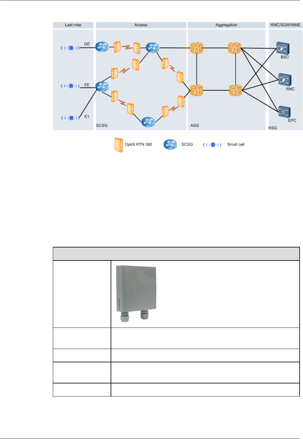
Figure 1-2 RTN 360 working with the SCSG
1.2 Product Specifications
RTN 360's specifications meet the requirements of service backhaul for small cell base
stations. In addition, RTN 360 features excellent immunity to interference, and is easy to
install and maintain.
Table 1-1 Product Specifications
Product Specifications
Appearance
Dimensions (H x
W x D)/Weight
192.5 mm x 192.5 mm x 70 mm/2.5 kg
Antenna Built-in panel antenna
Operating
frequency band
59 GHz to 64 GHz
Duplex mode TDD
OptiX RTN 360 Radio Transmission System
Product Description 1 Product Introduction
Issue 01 (2016-01-15) Huawei Proprietary and Confidential
Copyright © Huawei Technologies Co., Ltd.
3

Product Specifications
Radio working
mode (modulation
scheme/channel
spacing)
Modulation scheme: QPSK, 16QAM, 32QAM
Channel spacing: 200 MHz
AM Supported
Air-interface
throughput
≥ 800 Mbit/s
Maximum
transmission
distance
300 m
Service port Two GE electrical service ports
RF configuration
mode
1+0 configuration
Power supply
mode
Power over Ethernet (PoE), supplied by the AC power injector (PI),
DC power injector (PI), and other standard power sourcing
equipment (PSE)
Basic Ethernet
features
lE-Line/E-LAN
lQinQ
lQoS
lHQoS
lSynchronous Ethernet
1.3 Site Configurations
RTN 360s are usually powered by power injector (PI) or other standard power sourcing
equipment (PSE). RTN 360s can form sites providing one-direction, two-direction, or multi-
direction microwave links.
1.3.1 Sites Providing One-Direction Microwave Links
If a small cell base station is located at the end of a transmission link, an RTN 360 is required
to provide a 1+0 unprotected microwave link. The RTN 360 receives power signals and
service signals from power infector (PI).
Figure 1-3 illustrates configurations of a site providing a one-direction microwave link.
OptiX RTN 360 Radio Transmission System
Product Description 1 Product Introduction
Issue 01 (2016-01-15) Huawei Proprietary and Confidential
Copyright © Huawei Technologies Co., Ltd.
4
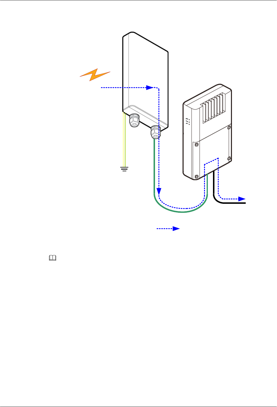
Figure 1-3 Site providing a one-direction microwave link
P&E
GE
To Small
cell
P&E
RTN 360
Power
Injector
Down link Service
From a
remote
RTN 360
NOTE
If a small cell base station can serve as standard PSE, RTN 360s can directly receive power signals and
service signals from the small cell base station.
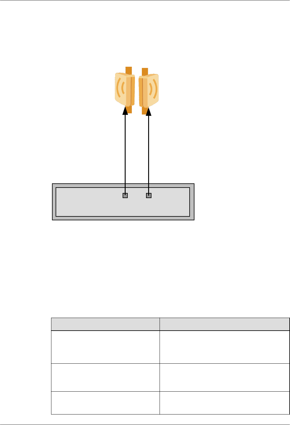
1.3.2 Sites Providing Two-Direction Microwave Links
If a small cell base station is an intermediate node on a transmission link, two RTN 360s are
required to provide two 1+0 unprotected microwave links in different directions. RTN 360s
receive power signals and service signals from the Dock of the small cell base station.
Figure 1-4 illustrates configurations of a site providing two microwave links in different
directions.
OptiX RTN 360 Radio Transmission System
Product Description 1 Product Introduction
Issue 01 (2016-01-15) Huawei Proprietary and Confidential
Copyright © Huawei Technologies Co., Ltd.
5
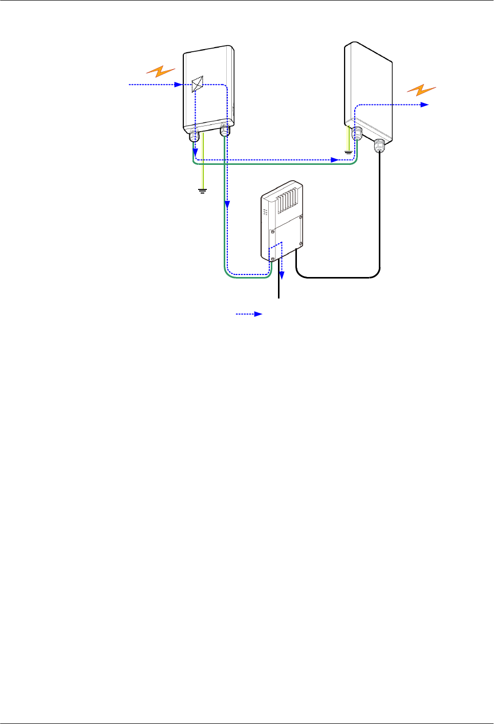
Figure 1-4 Site providing two microwave links in different directions
P&E1
To Small cell
P&E
RTN 360
Power
Injector
Down link Service
RTN 360
From a remote
RTN 360 To a remote
RTN 360
GE1 P&E2
LAN Switch
A site providing two-direction microwave links can work together with RTN B20 PIs to
receive service signals from small cell base stations and power signals. Two RTN 360s are
cascaded through GE(e) ports for service aggregation.
1.3.3 Sites Providing Multi-direction Microwave Links
If a macro base station connects to multiple small cell base stations in a star topology, in
addition to multiple RTN 360s, an OptiX RTN 900 (IDU) (for example, an IDU 950A) or
other power sourcing equipment (PSE) is required. The IDU supplies power to the RTN 360s
through a PoE board (for example, an EG4P board) and aggregates services.
Figure 1-5 illustrates configurations of a site providing multi-direction microwave links.
OptiX RTN 360 Radio Transmission System
Product Description 1 Product Introduction
Issue 01 (2016-01-15) Huawei Proprietary and Confidential
Copyright © Huawei Technologies Co., Ltd.
6
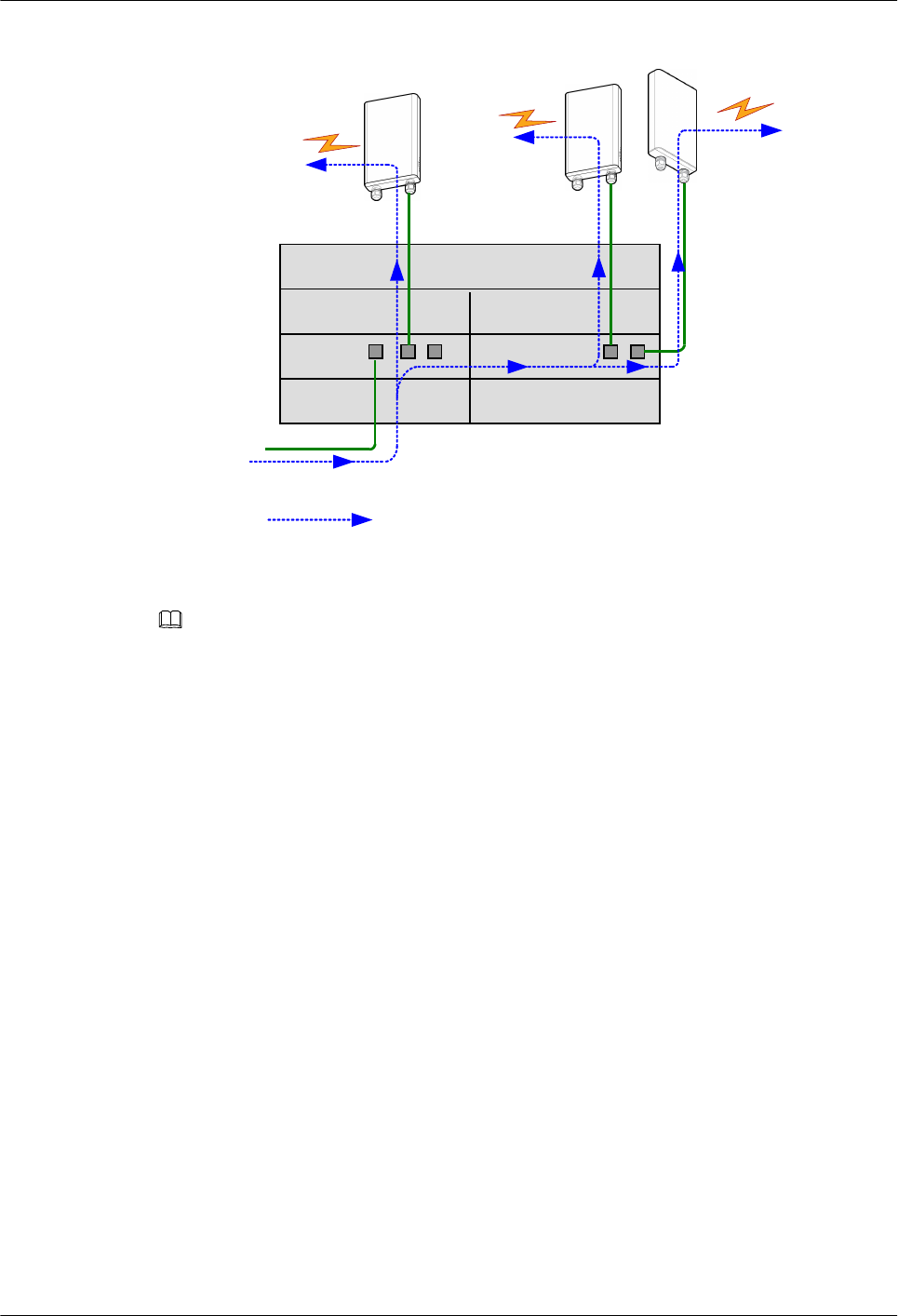
Figure 1-5 Site providing multi-direction microwave links
EG4P
ISV3
ISV3
EG4P
P&E P&E
IDU 950A
To a remote
RTN 360 To a remote
RTN 360
To a remote
RTN 360
From EPC
P&E
CSHO
Downlink service
NOTE
In addition to RTN 360s, the OptiX RTN 900 IDU may connect to FOs or ODUs operating at other
frequency bands to implement backhaul.
OptiX RTN 360 Radio Transmission System
Product Description 1 Product Introduction
Issue 01 (2016-01-15) Huawei Proprietary and Confidential
Copyright © Huawei Technologies Co., Ltd.
7

2 Functions and Features
About This Chapter
RTN 360 provides a variety of functions and features.
2.1 Integration
RTN 360 integrates a built-in antenna and uses a wide frequency band design, which allows a
single chassis to cover the entire V-band.
2.2 TDD
Time division duplex (TDD) has unique advantages over frequency division duplex (FDD) in
asymmetric transmission and high frequency spectrum resource utilization.
2.3 Automatic Frequency Selection
RTN 360 supports automatic frequency selection, which enables it to automatically select an
interference-free channel as the working channel.
2.4 Adaptive Modulation
Adaptive modulation (AM) technology automatically adjusts the modulation scheme based on
channel quality.
2.5 Power over Ethernet
The RTN 360 provides a P&E port through which the RTN 360 supports power over Ethernet
(PoE) as a powered device (PD).
2.6 Ethernet Service Processing Capability
RTN 360 can process native Ethernet services.
2.7 QoS
RTN 360 supports quality of service (QoS) functions, including traffic classification, traffic
policing, congestion avoidance, queue scheduling, and traffic shaping.
2.8 Clock Features
RTN 360's clock features meet clock transmission requirements of mobile communications
networks and offer a wide selection of clock protection mechanisms.
2.9 Network Management
RTN 360 supports multiple network management modes and provides comprehensive
management information exchange solutions.
OptiX RTN 360 Radio Transmission System
Product Description 2 Functions and Features
Issue 01 (2016-01-15) Huawei Proprietary and Confidential
Copyright © Huawei Technologies Co., Ltd.
8

2.10 Rapid Deployment
A variety of technologies are used to simplify RTN 360 installation so that wireless
installation personnel can deploy an RTN 360 within 30 minutes.
2.11 Easy Maintenance
RTN 360 supports contact-free maintenance, powerful equipment-level OAM functions, and
end-to-end TP-Assist.
2.12 Security Management
RTN 360 works with its network management system (NMS) to prevent unauthorized logins
and operations, ensuring equipment management security.
2.13 Energy Saving
RTN 360 consumes less energy by using:
2.14 Environmental Protection
RTN 360 is designed to meet environmental protection requirements. The product complies
with restriction of hazardous substances (RoHS) directives.
OptiX RTN 360 Radio Transmission System
Product Description 2 Functions and Features
Issue 01 (2016-01-15) Huawei Proprietary and Confidential
Copyright © Huawei Technologies Co., Ltd.
9
2.1 Integration
RTN 360 integrates a built-in antenna and uses a wide frequency band design, which allows a
single chassis to cover the entire V-band.
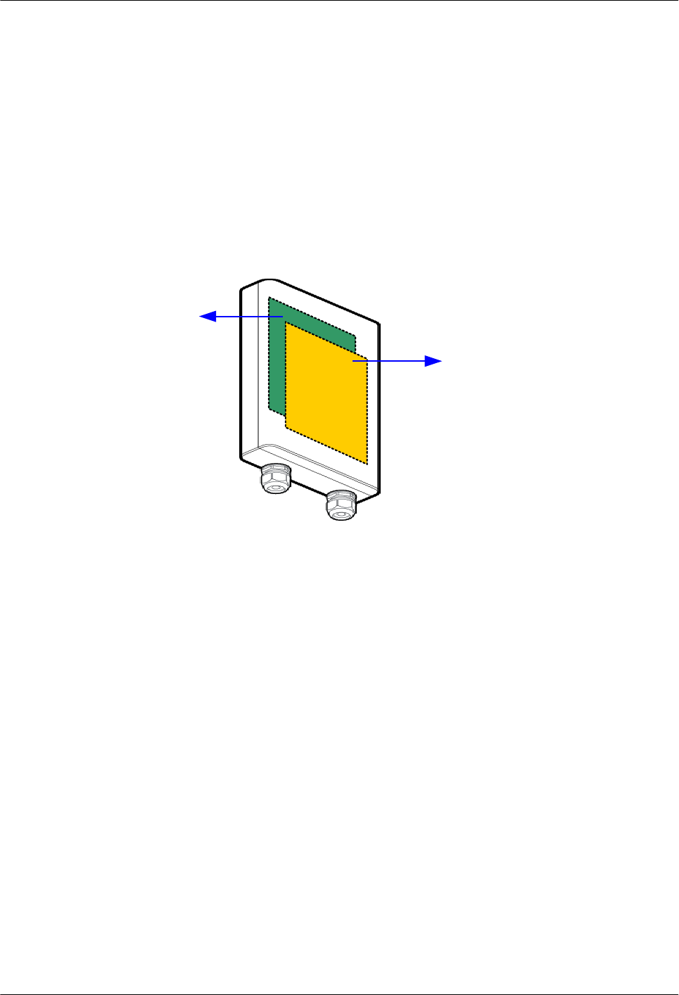
Built-in Antenna
RTN 360 integrates its system control unit, clock unit, power unit, baseband unit, RF unit, and
antenna into a single chassis. See Figure 2-1.
Figure 2-1 Integrated chassis with a built-in antenna
Panel
antenna
Baseband
board
Such a highly integrated design facilitates quick and flexible installation of RTN 360s in full-
outdoor scenarios.
Wide Frequency Band
RTN 360 uses a wide frequency band design, which enables a single chassis to cover the
entire V-band from 59 GHz to 64 GHz. This eliminates the need to distinguish TX high and
low sites, which means that spare parts need to be prepared for only one equipment model.
Both RTN 360 and Huawei small cell base stations can be installed on walls and poles. They
are similar in appearance and look harmonious when installed together.
2.2 TDD
Time division duplex (TDD) has unique advantages over frequency division duplex (FDD) in
asymmetric transmission and high frequency spectrum resource utilization.
In FDD mode, symmetric frequencies are required to function as the uplink and downlink
channels. The V-band is license-free in most areas and may be used by multiple users, and it
is difficult to obtain interference-free symmetric frequencies. Therefore, RTN 360 uses TDD
mode.
OptiX RTN 360 Radio Transmission System
Product Description 2 Functions and Features
Issue 01 (2016-01-15) Huawei Proprietary and Confidential
Copyright © Huawei Technologies Co., Ltd.
10
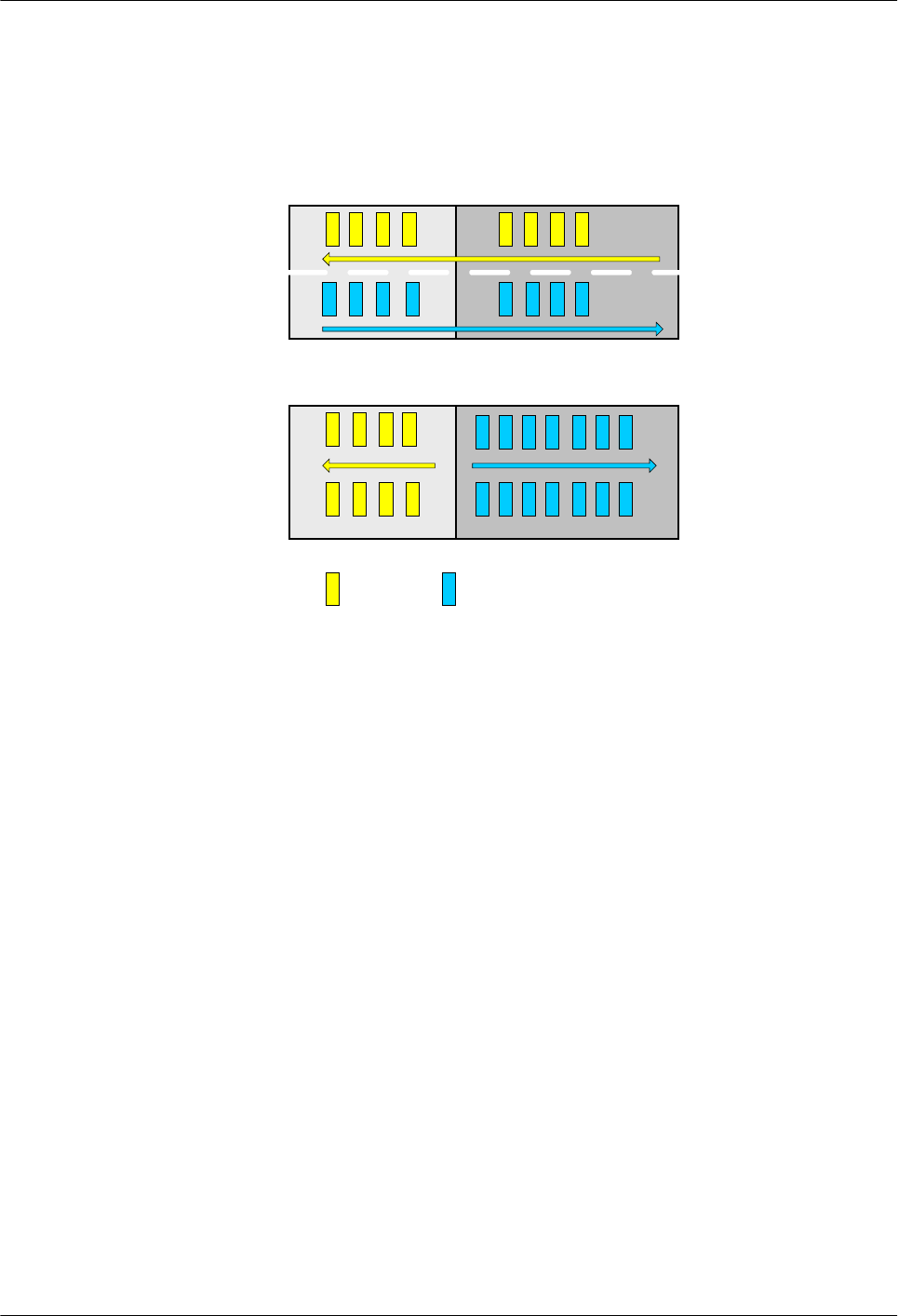
In TDD mode, asymmetric frequencies are used. Uplink and downlink data is transmitted in
different time periods. The ratio of timeslots for uplink data to those for downlink data can be
configured based on service requirements, flexibly using frequency resources.
Figure 2-2 Comparison between FDD and TDD modes
t0 t1
FDD
f1
f2
t0 t1
TDD f1 or f2
Downlink
data
Uplink
data
Using TDD mode, RTN 360 has the following advantages:
lOne RTN 360 can cover the operating frequency band (59 GHz to 64 GHz), eliminating
the need to distinguish TX high and low sites.
lTimeslots for uplink and downlink data can be flexibly adjusted based on actual traffic.
The ratio of timeslots for uplink data to those for downlink data can be configured to 5:1,
4:1, 3:1, 2:1, 1:1, 1:2, 1:3, 1:4, or 1:5.
2.3 Automatic Frequency Selection
RTN 360 supports automatic frequency selection, which enables it to automatically select an
interference-free channel as the working channel.
RTN 360 scans frequencies within a specified range to select interference-free channels. See
Figure 2-3.
Automatic frequency selection applies to the following two scenarios:
lDuring commissioning in site deployment, this function is used to obtain interference-
free channels, releasing engineers from planning microwave link frequencies.
lFor an in-service RTN 360, this function is used to reselect and switch to an interference-
free channel if the current microwave link is interrupted or fails due to interference on
the working channel, improving microwave links' immunity to interference.
OptiX RTN 360 Radio Transmission System
Product Description 2 Functions and Features
Issue 01 (2016-01-15) Huawei Proprietary and Confidential
Copyright © Huawei Technologies Co., Ltd.
11
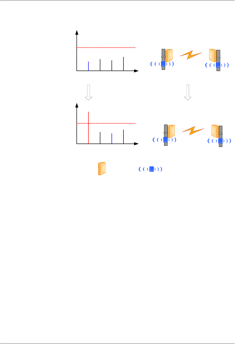
Figure 2-3 Automatic frequency selection diagram
f0 f1 f2 f3
V-Band
V-Band
f0
Interference
signal strength
f0 f1 f2 f3
V-Band
V-Band
f2
f0 interference signal
becoming stronger
Automatically
selecting f2
V-Band
RTN 360 Small cell
base station
Interference
signal threshold
Interference
signal threshold
2.4 Adaptive Modulation
Adaptive modulation (AM) technology automatically adjusts the modulation scheme based on
channel quality.
Modulation Scheme and Air-interface Capacity
When AM technology is enabled and the same channel spacing is used, the available radio
service bandwidth varies according to the modulation scheme: the higher the modulation
efficiency, the higher the bandwidth of the transmitted services.
lWhen channel conditions are favorable (such as on sunny days), the equipment uses a
higher-order modulation scheme to transmit more user services. This improves
transmission efficiency and spectrum utilization of the system.
lWhen channel conditions are unfavorable (such as on stormy or foggy days), the
equipment uses a lower-order modulation scheme to ensure that higher-priority services
are transmitted first. If some lower-priority queues become congested due to a lack of
available bandwidth, some or all interfaces in these queues are discarded. This method
improves the anti-interference capabilities of a microwave link and ensures link
availability for high-priority services.
OptiX RTN 360 Radio Transmission System
Product Description 2 Functions and Features
Issue 01 (2016-01-15) Huawei Proprietary and Confidential
Copyright © Huawei Technologies Co., Ltd.
12
Modulation Scheme Shift and Service Priorities
For Ethernet services transmitted through IP microwave, priorities can be set based on the
service bandwidth and QoS policies corresponding to the current modulation scheme, to
control service transmission. The transmission of services with the highest priority is ensured.
With the QoS technology, ethernet services are scheduled to queues with different priorities.
The services in different queues are transmitted to the microwave port after running the queue
scheduling algorithm. When modulation scheme switching occurs, certain queues may be
congested due to insufficient capacity at the air interface. As a result, certain services or all
the services in these queues are discarded.
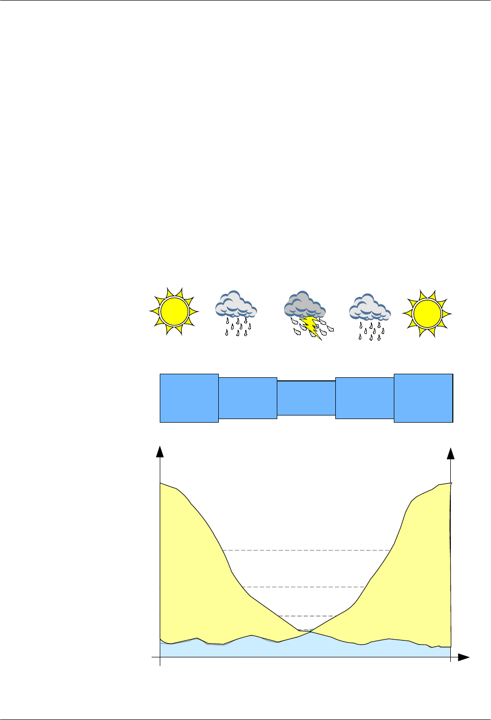
Adaptive Modulation
Figure 2-4 shows how the modulation scheme shifts step by step according to weather
changes and how modulation schemes affect service throughput and reliability. In this
example, the modulation scheme of guaranteed AM capacity is QPSK and the modulation
scheme of full AM capacity is 32QAM.
Figure 2-4 Adaptive modulation
QPSK
16QAM
32QAM
16 QAM
QPSK
32 QAM
99.999%
Receive Signal
99.995%
99.99%
High-priority service
Low-priority
service
16QAM 32QAM
Low-priority
service
OptiX RTN 360 Radio Transmission System
Product Description 2 Functions and Features
Issue 01 (2016-01-15) Huawei Proprietary and Confidential
Copyright © Huawei Technologies Co., Ltd.
13

Characteristics
The AM technology used by RTN 360 has the following characteristics:
lSupports the QPSK, 16QAM, and 32QAM modulation schemes.
lCan configure both the lowest-order modulation scheme (also called reference scheme or
modulation scheme of guaranteed AM capacity) and the highest-order modulation
scheme (also called nominal scheme or modulation scheme of full AM capacity).
lCan switch modulation schemes without changing the transmit frequency, receive
frequency, or channel spacing.
lSwitches modulation schemes step-by-step.
lFeatures hitless switching. When the modulation scheme is downshifted, high-priority
services are not affected while low-priority services are discarded. Switching is
successful even when 100 dB/s channel fast fading occurs.
2.5 Power over Ethernet
The RTN 360 provides a P&E port through which the RTN 360 supports power over Ethernet
(PoE) as a powered device (PD).
In PoE mode, an outdoor network cable carries Ethernet service signals along with DC power
signals. PoE has the following advantages:
lReduces the number of power cables and simplifies installation.
An RTN 360 can work with a power injector (PI) to implement power over Ethernet through
its P&E port. See Figure 2-5.
Figure 2-5 Working with a PI
Power
injector
P&E port
GE signal
Power
signal
P&E port
Injecting
OptiX RTN 360 Radio Transmission System
Product Description 2 Functions and Features
Issue 01 (2016-01-15) Huawei Proprietary and Confidential
Copyright © Huawei Technologies Co., Ltd.
14
An RTN 360 can also work with other power sourcing equipment (PSE), such as an RTN 900
IDU, to implement power over Ethernet through its P&E port. For example, when an OptiX
RTN 905 2E IDU is used, it provides two PoE ports, as shown in Figure 2-6.
Figure 2-6 Working with an OptiX RTN 900
GE and -48V signal
P&E port
RTN 905 2E
P&E port
GE1/P1 GE2/P2
2.6 Ethernet Service Processing Capability
RTN 360 can process native Ethernet services.
Table 2-1 Ethernet service processing capability
Item Description
Service ports Two GE service ports
lThe first GE port is a P&E port.
lThe second GE port is a fixed electrical port.
Port attributes The GE electrical port supports 10M full-
duplex, 100M full-duplex, 1000M full-duplex,
and auto-negotiation.
Ethernet service types lE-Line
lE-LAN
OptiX RTN 360 Radio Transmission System
Product Description 2 Functions and Features
Issue 01 (2016-01-15) Huawei Proprietary and Confidential
Copyright © Huawei Technologies Co., Ltd.
15

Item Description
Range of maximum frame length 1518 bytes to 9600 bytes
VLAN lAdds, deletes, and swaps VLAN tags that
comply with IEEE 802.1Q/P, and forwards
packets based on VLAN tags.
lProcesses packets based on the port tag
attribute (Tag/Hybrid/Access).
lThe VLAN ID ranges from 1 to 4094.
QinQ lAdds, deletes, and swaps S-TAG tags, and
forwards packets based on S-VLAN tags.
lThe S-VLAN ID ranges from 1 to 4094.
lThe QinQ type domain is configurable. The
default value is 88A8.
MAC address management lSupports MAC address self-learning for E-
LAN services in two learning modes: SVL
and IVL.
lFilters blacklisted MAC addresses.
lSets static MAC address entries.
lSupports a MAC address table with a
maximum of 16K capacity (including static
and blacklist entries).
Link-state pass through (LPT) Supports simple LPT. When a microwave link is
faulty, the related RTN 360 automatically
disables the remote Ethernet port that is
connected to a user-to-network interface (UNI)
device.
QoS/HQoS Supports QoS and HQoS. For details, see 2.7
QoS.
Traffic control Supports IEEE 802.3x-compliant traffic control.
ETH OAM lSupports IEEE 802.1ag- and IEEE 802.3ah-
compliant ETH OAM.
lSupports ITU-T Y.1731-compliant packet
loss measurement, delay measurement, and
delay variation measurement.
Ethernet performance monitoring lSupports IETF RFC 2819-compliant remote
network monitoring (RMON).
lSupports measurement of real-time and
historical traffic, bandwidth utilization, and
packet loss for ports.
Synchronous Ethernet Supported
Link Layer Discovery Protocol (LLDP) Supported
OptiX RTN 360 Radio Transmission System
Product Description 2 Functions and Features
Issue 01 (2016-01-15) Huawei Proprietary and Confidential
Copyright © Huawei Technologies Co., Ltd.
16

NOTE
lRTN 360 supports a maximum of 64 E-Line services. The supported E-Line services fall into the
following types:
lPort-based E-Line services
lPort+VLAN-based E-Line services
lPort+QinQ-based E-Line services
lRTN 360 supports only one E-LAN service. The supported E-LAN services fall into the following types:
lIEEE 802.1d bridge-based E-LAN services
lIEEE 802.1Q bridge-based E-LAN services
lIEEE 802.1ad bridge-based E-LAN services
2.7 QoS
RTN 360 supports quality of service (QoS) functions, including traffic classification, traffic
policing, congestion avoidance, queue scheduling, and traffic shaping.
QoS provides different levels of service quality in certain aspects of services as required, such
as bandwidth, delay, jitter, and packet loss ratio. This ensures that the request and response of
a user or application reaches an expected quality level.
QoS Functions
Table 2-2 QoS functions
Function Description
Simple traffic classification (DiffServ) lSupports one DiffServ (DS) domain.
lMaps Ethernet services into different per-hop
behaviors (PHBs) based on C-VLAN
priorities, S-VLAN priorities, IP
differentiated services code point (DSCP)
values, or MPLS experimental bits (EXP)
values.
Complex traffic classification Supports traffic classification by MAC address,
VLAN ID, VLAN priority, IP address, DSCP
value, protocol type, port ID, or Internet Control
Message Protocol (ICMP) type at ports.
ACL Supports ACL based on complex traffic
classification.
Traffic policing Supports committed access rate (CAR) based on
complex traffic classification at ports and
supports the setting of the committed
information rate (CIR), peak information rate
(PIR), committed burst size (CBS), and peak
burst size (PBS).
OptiX RTN 360 Radio Transmission System
Product Description 2 Functions and Features
Issue 01 (2016-01-15) Huawei Proprietary and Confidential
Copyright © Huawei Technologies Co., Ltd.
17

Function Description
Congestion avoidance lSupports tail drop at both microwave ports
and Ethernet ports.
lSupports weighted random early detection
(WRED) at both microwave ports and
Ethernet ports.
Queue scheduling lSupports eight levels of priority scheduling
at both Ethernet ports and microwave ports.
lFlexibly sets the queue scheduling scheme
for each Ethernet port and microwave port.
The queue scheduling schemes include strict
priority (SP), weighted round robin (WRR),
and SP+WRR.
Traffic shaping lSupports traffic shaping for egress queues
and egress ports.
lSupports the setting of PIR in increments of
64 kbit/s and the setting of PBS.
HQoS lFor QinQ NNI ports, supports two levels of
queue scheduling for QinQ queues and
egress queues, and supports four levels of
rate limiting for QinQ queues, QinQ, egress
queues, and egress ports.
lFor UNI ports, supports three levels of queue
scheduling for V-UNI egress queues, V-UNI
egress groups, and egress queues, and
supports five levels of rate limiting for V-
UNI egress queues, V-UNI egress, VUNI
egress groups, egress queues, and egress
ports.
Figure 2-7 Typical QoS application
Forwarding
Queue scheduling
Ingress Egress
Packet switching
Congestion
avoidance
Buffer queue
Threshold
Queue traffic
shaping
Scheduling
Drop
...
......
Port shaping
Token
bucket
............
......
......
......
......
......
...
Simple traffic
classification
Mapping
DiffServ
CoS x
...
CoS z
Traffic
monitoring
CAR
Token
bucket
Flow
Complex traffic
classification
OptiX RTN 360 Radio Transmission System
Product Description 2 Functions and Features
Issue 01 (2016-01-15) Huawei Proprietary and Confidential
Copyright © Huawei Technologies Co., Ltd.
18
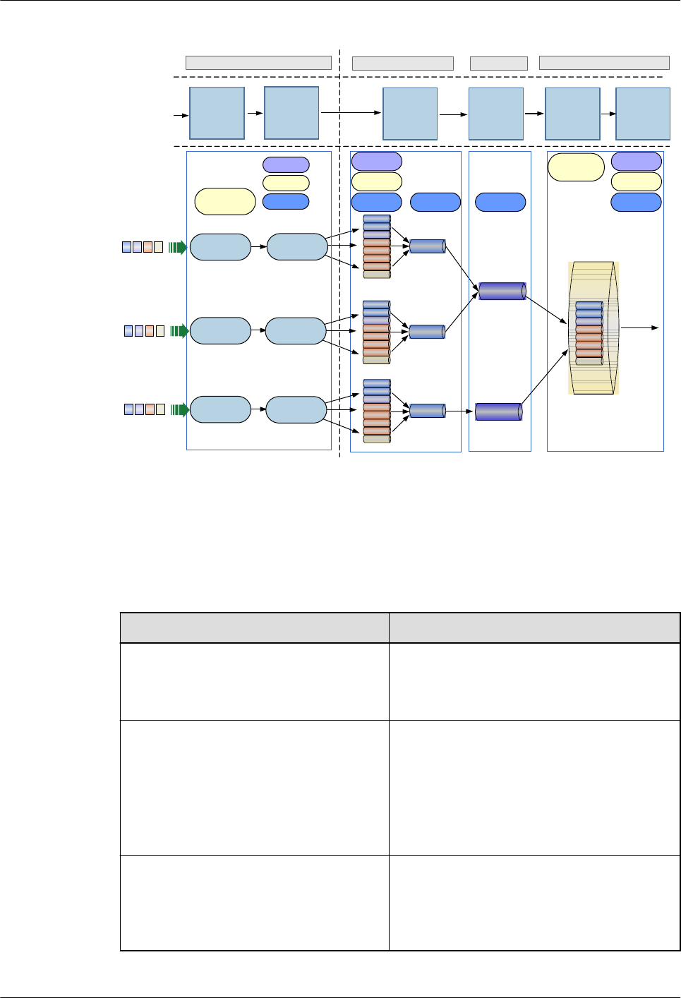
Figure 2-8 Typical HQoS application
HQoS
application point
HQoS
technologies
Ingress port Egress port
Apply the
DS domain
HQoS
configuration Apply the
port policy
Ethernet
packets of
user A
V-UNI
Port
Traffic
shaping
Traffic
shaping
CS7
CS6
EF
AF4
AF3
AF2
AF1
BE
Complex
traffic
classification
V-UNI
CS7
CS6
EF
AF4
AF3
AF2
AF1
BE
Complex
traffic
classification
V-UNI
CS7
CS6
EF
AF4
AF3
AF2
AF1
BE
Complex
traffic
classification
Queue
scheduling
Congestion
Avoidance
Traffic
shaping
ACL
CAR
CoS
DS mapping
in the egress
direction
DS mapping
in the ingress
direction
CS7
CS6
EF
AF4
AF3
AF2
AF1
BE
Queue
scheduling
Congestion
Avoidance
Traffic
shaping
Ethernet
packets of
user B
Ethernet
packets of
user C
Limit the
bandwidth
for the V-
UNI group
Apply the V-
UNI egress
policy
Apply the DS
domain
Apply the port
policy
V-UNI V-UNI group
V-UNI
group
V-UNI
group
Ethernet
packets
Simple
traffic
classification
Simple
traffic
classification
Simple
traffic
classification
2.8 Clock Features
RTN 360's clock features meet clock transmission requirements of mobile communications
networks and offer a wide selection of clock protection mechanisms.
Item Description
Clock working mode lTracing
lHoldover
lFree-run
Clock source lMicrowave link clock
lSynchronous Ethernet clock
NOTE
When two RTN 360s form a hop of microwave
link, one is the master NE tracing the Synchronous
Ethernet clock, and the other is the slave NE
tracing the microwave link clock.
Synchronization Status Message (SSM)
protocol or extended SSM protocol
Supported. SSM information can be
transmitted in the following modes:
lMicrowave link
lSynchronous Ethernet
OptiX RTN 360 Radio Transmission System
Product Description 2 Functions and Features
Issue 01 (2016-01-15) Huawei Proprietary and Confidential
Copyright © Huawei Technologies Co., Ltd.
19

2.9 Network Management
RTN 360 supports multiple network management modes and provides comprehensive
management information exchange solutions.
Network Management Modes
RTN 360 supports the following network management modes:
lUses the iManager U2000 Web LCT to manage local and remote NEs on a per-NE basis.
lUses the Mobile LCT to manage local NEs on a per-NE basis through Wi-Fi.
lUses the iManager U2000-T to manage Huawei OptiX RTN NEs and Huawei optical
transmission products in a unified manner. The iManager U2000-T is also able to
manage transport networks in a unified manner.
lUses the iManager U2000-M, which manages Huawei mobile communications network
products in a unified manner, to manage RTN 360 using its NE Explore.
lUses SNMP Get to query alarms, performance events, and RMON performance.
Network Management Information Exchange Solutions
Table 2-3 DCN information exchange solutions
Item Specifications
DCN channel Data
communicatio
ns channel
(DCC) bytes
Three Huawei-defined DCC bytes in a microwave
frame
Network
management
system (NMS)
port
One NMS port
In-
band
DCN
Micr
owav
e link
All in-band DCN channels are marked by one
VLAN ID. The bandwidth of an in-band DCN
channel is configurable.
GE
port
All in-band DCN channels are marked by one
VLAN ID. The bandwidth of an in-band DCN
channel is configurable.
Network
management
protocol
HWECC
protocol
Supported
IP protocol Supported
L2DCN Supported
OptiX RTN 360 Radio Transmission System
Product Description 2 Functions and Features
Issue 01 (2016-01-15) Huawei Proprietary and Confidential
Copyright © Huawei Technologies Co., Ltd.
20
2.10 Rapid Deployment
A variety of technologies are used to simplify RTN 360 installation so that wireless
installation personnel can deploy an RTN 360 within 30 minutes.
So that it can be deployed rapidly, RTN 360:
lUses TDD mode, in which signals are transmitted and received over the same frequency,
eliminating the need to distinguish TX high and low sites and requiring spare parts for
only one equipment model.
lSupports automatic frequency selection, simplifying microwave link frequency planning.
lIntegrates panel antennas, simplifying installation.
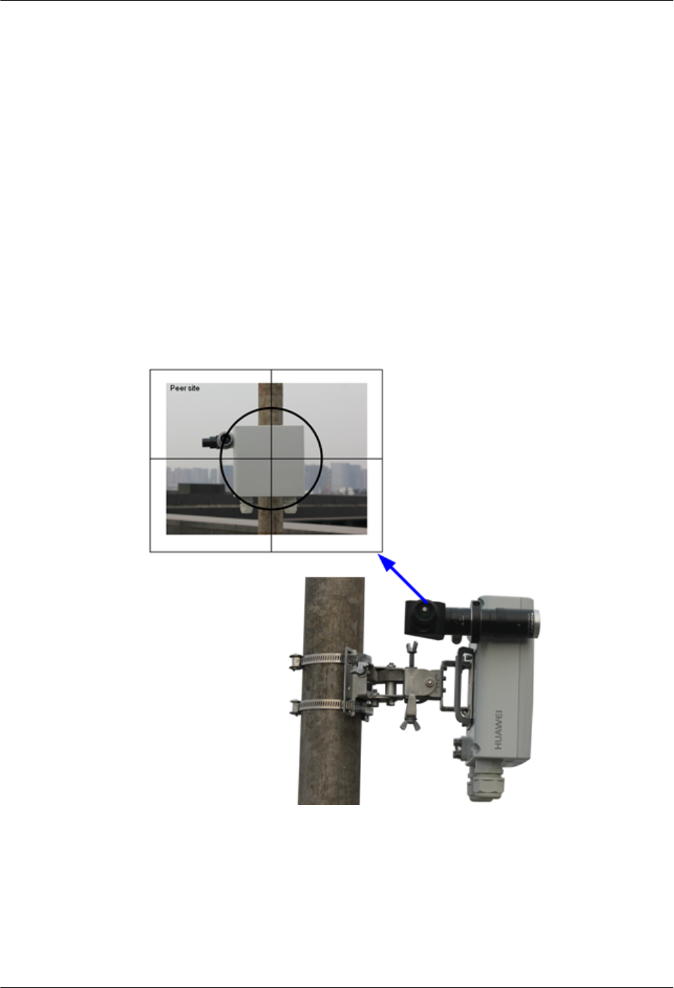
lUses an alignment scope to facilitate antenna alignment, improving installation
efficiency.
Figure 2-9 Aligning antennas using an alignment scope
lSupports power over Ethernet. RTN 360 can work with power injector (PI), or other
power sourcing equipment (PSE) to receive service signals and power signals,
facilitating deployment.
lSupports configuration-free commissioning using a USB flash drive.
lManages NEs on a per-NE basis using a Wi-Fi module.
OptiX RTN 360 Radio Transmission System
Product Description 2 Functions and Features
Issue 01 (2016-01-15) Huawei Proprietary and Confidential
Copyright © Huawei Technologies Co., Ltd.
21
2.11 Easy Maintenance
RTN 360 supports contact-free maintenance, powerful equipment-level OAM functions, and
end-to-end TP-Assist.
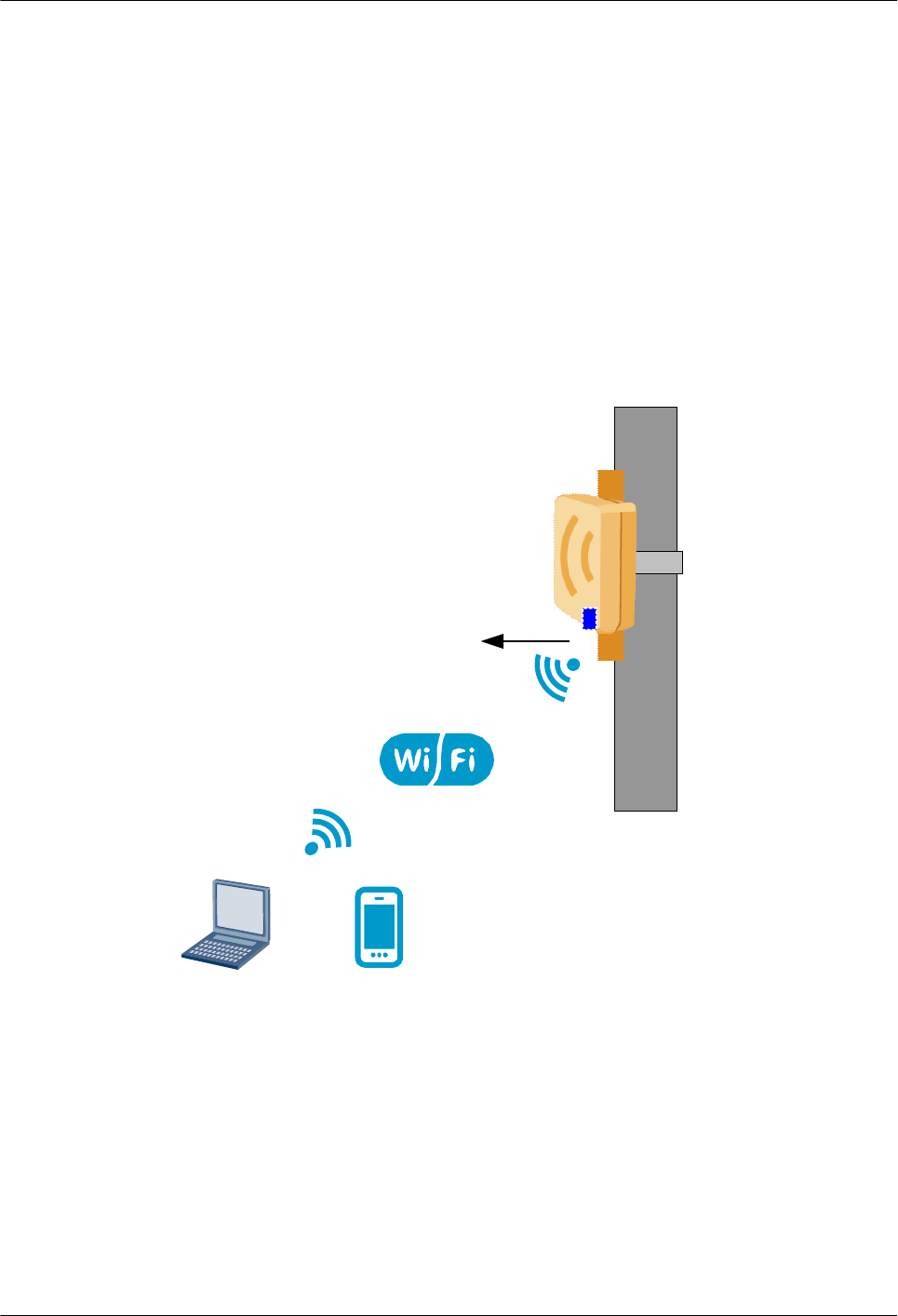
2.11.1 Contact-Free Maintenance
RTN 360 supports contact-free maintenance with its Wi-Fi module.
The Mobile LCT, also called Mobile Deployment Terminal (MDT) or Web LCT can use Wi-
Fi to connect to a local RTN 360 with a Wi-Fi module.
Figure 2-10 Contact-free maintenance
Wi-Fi module
Mobile LCT
Web LCT
or
OptiX RTN 360 Radio Transmission System
Product Description 2 Functions and Features
Issue 01 (2016-01-15) Huawei Proprietary and Confidential
Copyright © Huawei Technologies Co., Ltd.
22
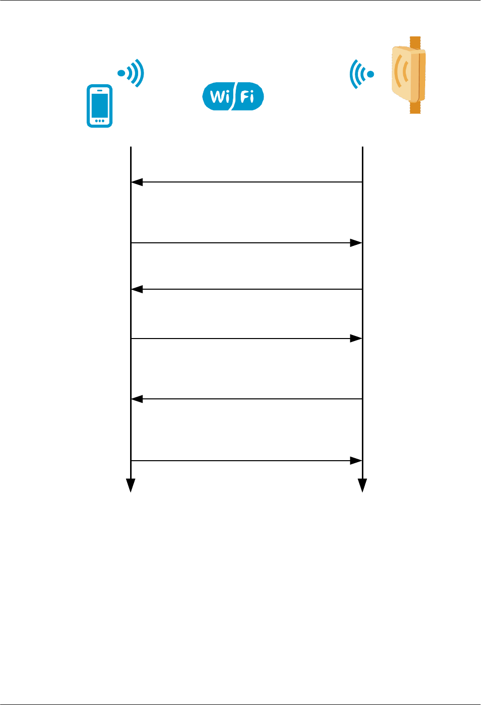
Figure 2-11 Access process through Wi-Fi
The NE broadcasts an SSID.
(Optional)
The Mobile LCT searches for and
selects an SSID.
The user enters a Wi-Fi password
and accesses the network.
After passing authentication, the Mobile
LCT connects to the network.
The Mobile LCT logs in to the NE using
SSL and then performs management
and query operations.
The NE automatically allocates an
IP access to the mobile phone.
NE
After connecting to a local NE through Wi-Fi, the Mobile LCT or Web LCT can be used to
configure the NE, and query NE alarms, and the Web LCT can also be used to query
performance and logs, facilitating commissioning and maintenance.
2.11.2 Equipment-Level OAM
RTN 360 provides various operation, administration and maintenance (OAM) functions that
effectively reduce equipment maintenance costs.
Table 2-4 describes the OAM functions supported by RTN 360.
OptiX RTN 360 Radio Transmission System
Product Description 2 Functions and Features
Issue 01 (2016-01-15) Huawei Proprietary and Confidential
Copyright © Huawei Technologies Co., Ltd.
23

Table 2-4 Equipment-level OAM functions
Function Description
Management and
monitoring
lSupports unified management of microwave transmission networks and optical
transmission networks, and end-to-end service creation and management using
the iManager U2000-T.
lSupports creation, configuration, and operation management of an RTN 360
using the iManager U2000-M.
lReports various alarms and performance events.
lSupports RMON performance events.
lMeasures real-time and historical traffic and bandwidth utilization for ports.
lMeasures congestion-caused packet loss information by traffic class and egress
queue for ports.
lAllows users to observe and analyze Ethernet packets over a port through port
mirroring.
lCaptures headers of specified Ethernet packets.
lQueries equipment temperatures.
lMonitors key radio transmission performance indicators, such as the microwave
transmit power, receive power, signal-to-noise ratio (SNR), and air-interface bit
error rate (BER), and displays them graphically.
lSupports frequency scanning to help identify co-channel interference and
adjacent-channel interference.
lCollects one-click fault diagnosis information.
lSupports the connection of the Mobile LCT or Web LCT to the equipment
using Wi-Fi during equipment commissioning or maintenance.
Diagnosis tests lSupports pseudo random binary sequence (PRBS) tests at microwave ports.
lSimulates Ethernet meters to test the packet loss ratio, delay, and throughput.
lSupports various loopback functions at service ports and microwave ports.
ETH OAM lSupports IEEE 802.1ag- and IEEE 802.3ah-compliant ETH OAM.
lSupports ITU-T Y.1731-compliant packet loss measurement, delay
measurement, and delay variation measurement.
lSupports loopback tests for Ethernet services.
Database management lBacks up and restores NE databases remotely using the iManager U2000-T.
lBacks up and restores NE data using USB flash drives.
lBacks up and restores databases of peer NEs on microwave links.
OptiX RTN 360 Radio Transmission System
Product Description 2 Functions and Features
Issue 01 (2016-01-15) Huawei Proprietary and Confidential
Copyright © Huawei Technologies Co., Ltd.
24

Function Description
Software management lSupports remote loading of NE software and data using the iManager U2000-T
and provides a complete NE upgrade solution, allowing rapid upgrades of the
entire network.
lUpgrades NE software using USB flash drives.
lSupports the not-stop forwarding (NSF) function, which prevents Ethernet
services from being interrupted by warm NE software resets.
lSupports hot patches so that you can upgrade software without interrupting
services.
lSupports software version rollback so that original system services are restored
in case of software upgrade failures.
2.11.3 Packet OAM (TP-Assist)
In compliance with the network-centered, service-centered, and intelligent packet network
O&M trend, Huawei promotes a brand new O&M system based on the TP-Assist solution.
The O&M system covers the entire O&M process from network planning to fault diagnosis.
Table 2-5 describes the packet OAM functions supported by RTN 360.
Table 2-5 Functions of the TP-Assist O&M system
Function Description Purpose
Professional planning service and planning
tools
Experienced planning expert teams
provide professional planning service.
Planning tool UniSTAR Designer,
embedded with the common network
HLD/LLD design templates and device/
board/interface capacity parameter
templates, is used. This tool is applicable
to various network planning scenarios
including new network construction,
network expansion, network migration,
and service adjustment.
Improves planning
efficiency.
Improves planning
accuracy.
End-to-end service deployment Deploys Native Ethernet (E-Line and E-
LAN) services and hybrid services in an
end-to-end manner.
Deploys services across microwave and
optical fibers in an end-to-end manner.
Quick service
configuration
Improves
configuration
accuracy.
OptiX RTN 360 Radio Transmission System
Product Description 2 Functions and Features
Issue 01 (2016-01-15) Huawei Proprietary and Confidential
Copyright © Huawei Technologies Co., Ltd.
25

Function Description Purpose
Automatic deployment of alarm
management with service deployment
Deploying ETH-OAM when deploying
Ethernet services in an end-to-end manner.
Avoids extra OAM
deployment
operations. Allows
the NE to
automatically report
alarms when a
service fault occurs.
One-click service connectivity test Supports one-click service connectivity
test for Ethernet services that are deployed
in an end-to-end manner.
Quick
commissioning
Lowers project
acceptance costs.
One-click service performance test Supports one-click packet loss, delay, and
delay jitter tests for Ethernet services that
are deployed in an end-to-end manner.
Automatic tests with no need for any
instrument
Simulating the Smartbits function,
supports delay, throughput, short-term
packet loss ratio, and long-term packet loss
ratio tests for VLAN-based E-Line
services.
IP packet marking and statistics collection Supports packet loss measurement for
point-to-point IP service flows.
Performance
monitoring and
measurement
Network-level
performance
monitoring and
measurement
system
The PMS embedded in the U2000 supports
unified monitoring and measurement of
any measurement object and performance
indicator in the network.
It supports 24-hour service status pre-
warning and monitoring, and provides
equipment performance threshold-crossing
alarms and network performance
threshold-crossing alarms.
Optimized
monitoring points,
rich service
monitoring methods
Visualized
monitoring;
network-level and
service-centered
monitoring
360-degree traffic
statistics and
monitoring based
on service paths
Allows all-service-layer (port and VLAN)
traffic statistics and monitoring in a service
view.
Supports QoS packet loss detection.
Visualized O&M Queries and display
of service paths
based on VLANs
For E-Line services, allows users to find
the service working path and protection
path views based VLANs.
For E-LAN services, allows users to find
the VLAN domain views based on
VLANs.
Service
visualization
Queries and display
of service paths
based on MAC
addresses
For E-LAN services, allows users to find
the actual MAC address forwarding path
views based on MAC addresses.
OptiX RTN 360 Radio Transmission System
Product Description 2 Functions and Features
Issue 01 (2016-01-15) Huawei Proprietary and Confidential
Copyright © Huawei Technologies Co., Ltd.
26

Function Description Purpose
Intelligent fault diagnosis Performs automatic fault diagnosis for
Ethernet services by layer (service/port)
and by level (connectivity/performance/
configuration).
Quickly outputs fault diagnosis reports on
a one-click operation GUI.
Intelligent fault
diagnosis
Cross-product fault
diagnosis
IP ping Responds to IP ping packets sent from
client equipment and then quickly narrows
down the fault location to the client
equipment or the transport network.
Support near-end or far-end IP ping
responding.
Supports initiating an IP ping test to the
near-end or far-end.
Network-level E-LAN service loop
detection
Quickly detects an E-LAN loop (if any) in
the service view.
Automatically shuts down a looped
service.
Displays the loopback path.
2.12 Security Management
RTN 360 works with its network management system (NMS) to prevent unauthorized logins
and operations, ensuring equipment management security.
Overview of Hardware Security
RTN 360 uses the following hardware security measures:
lMicrowave ports: The forward error correction (FEC) encoding mode is adopted and the
adaptive time-domain equalizer for baseband signals is used. This enables the microwave
ports to withstand strong interference. An interceptor cannot restore the content in a data
frame if coding details and service configurations are not obtained.
lModular design: Control units are separated from service units, and service units are
separated from each other. In this manner, a fault on any unit can be isolated, minimizing
the impact of the fault on other units in the system.
lCPU flow control: The data flow sent to the CPU for processing is classified and
controlled to prevent CPU resources from being exhausted by a large number of packets.
This ensures that the CPU operates properly under attacks.
lManagement port control: The protective cover for the maintenance compartment is kept
closed when the management port is not being used, preventing unauthorized access.
OptiX RTN 360 Radio Transmission System
Product Description 2 Functions and Features
Issue 01 (2016-01-15) Huawei Proprietary and Confidential
Copyright © Huawei Technologies Co., Ltd.
27

Overview of Software Security
RTN 360 processes two types of data: O&M data and service data. The two types of data are
transmitted over independent paths and do not affect each other. This enables services running
on an RTN 360 to be processed on two planes:
lManagement plane
The management plane provides access to the required equipment and management
functions, such as managing accounts and passwords, communication protocols, and
alarm reporting. Security features on the management plane implement secure access,
integrated security management, and all-round security audits.
lData plane
The data plane processes the service data flow entering the equipment and forwards
service packets according to the forwarding table. Security features on the data plane
ensure confidentiality and integration of user data by preventing malicious theft,
modification, and removal of user service packets. These features ensure reliable data
forwarding by protecting forwarding entries against malicious attacks and falsification.
Table 2-6 describes security functions provided by RTN 360.
Table 2-6 Security functions
Plane Function Description
Management plane Account and password
management
Manages and stores
maintenance accounts and
passwords.
Local authentication and
authorization
Authenticates and authorizes
accounts.
RADIUS authentication and
authorization
Authenticates and authorizes
remote accounts in a
centralized manner to
reduce maintenance costs.
Security log Records events related to
account management.
Operation log Records non-query
operations.
Syslog management Provides a standard solution
to offline storage of logs,
addressing insufficient
storage space.
TCP/IP attack defense Provides defense against
TCP/IP attacks, such as
error IP packet attacks,
Internet Control Message
Protocol (ICMP) ping and
Jolt attacks, and DoS
attacks.
OptiX RTN 360 Radio Transmission System
Product Description 2 Functions and Features
Issue 01 (2016-01-15) Huawei Proprietary and Confidential
Copyright © Huawei Technologies Co., Ltd.
28

Plane Function Description
Access control list Provides access control lists
based on IP addresses and
port IDs.
SSL/TLS encryption
communication (SSL is the
abbreviated form of Secure
Sockets Layer, and TLS is
the abbreviated form of
Transport Layer Security.)
Uses the SSL3.0 and
TLS1.0\1.1\1.2 protocols to
establish an encryption
channel based on a security
certificate.
Secure File Transfer
Protocol (SFTP)
Provides SFTP services.
Open Shortest Path First
(OSPF)
Uses the OSPFv2 protocol
for standard MD5
authentication.
Network Time Protocol
(NTP)
Uses the NTPv3 protocol for
MD5 authentication and
permission control.
Simple Network
Management Protocol
(SNMP)
Uses the SNMPv3 protocol
for authentication and data
encryption.
USB flash drive connection
control
Supports connection of only
authorized USB flash drives
based on a certificate file.
Wi-Fi connection control lSupports access through
a Wi-Fi password and
Wi-Fi encryption.
lSupports the hiding of
SSIDs.
lSupports the setting of
Wi-Fi access periods.
Data plane Flow control Controls traffic at ports.
Broadcast packets are
suppressed. Unknown
unicast packets and
multicast packets are
discarded. QoS is used to
control service traffic.
Discarding of incorrect
packets
Discards incorrect packets,
such as an Ethernet packet
shorter than 64 bytes.
Loop prevention Detects self-loops at service
ports and blocks self-looped
ports.
OptiX RTN 360 Radio Transmission System
Product Description 2 Functions and Features
Issue 01 (2016-01-15) Huawei Proprietary and Confidential
Copyright © Huawei Technologies Co., Ltd.
29

Plane Function Description
Access control of Layer 2
services
Filters static MAC addresses
in the static MAC address
table, provides a blacklist,
enables and disables the
MAC address learning
function, and filters packets
based on traffic
classification.
Service separation Includes Layer 2 logical
separation, split horizon,
and physical path
separation.
2.13 Energy Saving
RTN 360 consumes less energy by using:
lStreamlined design with minimum components
lHigh-efficient power modules
lLow-power components
2.14 Environmental Protection
RTN 360 is designed to meet environmental protection requirements. The product complies
with restriction of hazardous substances (RoHS) directives.
lThe product complies with RoHS, waste from electrical and electronic equipment
(WEEE), and Registration, Evaluation, Authorization and Restriction of Chemicals
(REACH) directives.
lThe product complies with compulsory packing restrictions that limit the size of the
package containing the equipment and accessories to three times that of the equipment
dimensions.
lAll hazardous substances contained in the package can degrade quickly.
lEvery plastic component that weighs over 25 g is labeled according to the ISO 11469
and ISO 1043-1 to ISO 1043-4 standards. All components and packaging come with
standard recycling labels.
lPlugs and connectors are easy to find and are compatible with standard tools.
lAll the attached materials, such as labels, are easy to remove. Certain types of
identifying information, such as silkscreens, are printed on the chassis.
OptiX RTN 360 Radio Transmission System
Product Description 2 Functions and Features
Issue 01 (2016-01-15) Huawei Proprietary and Confidential
Copyright © Huawei Technologies Co., Ltd.
30

3 Product Structure
About This Chapter
This chapter describes RTN 360's system architecture, service signal processing flow, external
ports, indicators, and labels.
3.1 System Architecture
RTN 360 integrates its functional units into a single chassis.
3.2 Service Signal Processing Flow
This section describes how the functional units of RTN 360 process power over Ethernet
(PoE) signals.
3.3 Ports
An RTN 360 has one GE port, one P&E port, and one maintenance compartment.
3.4 Indicators
RTN 360 has an STAT indicator and a USB port indicator.
3.5 Labels
A product nameplate label, electrostatic discharge (ESD) warning label, radiation warning
label, grounding label, and high temperature warning label are affixed on a chassis. Adhere to
any warnings on the labels when performing tasks to avoid personal injury and damage to
equipment.
OptiX RTN 360 Radio Transmission System
Product Description 3 Product Structure
Issue 01 (2016-01-15) Huawei Proprietary and Confidential
Copyright © Huawei Technologies Co., Ltd.
31
3.1 System Architecture
RTN 360 integrates its functional units into a single chassis.
An RTN 360 has a panel antenna and one physical board, the SLV1SHUA2 board. The
SLV1SHUA2 board is displayed as SHUA2 on the network management system (NMS) and
occupies logical slot 1.
The SHUA2 board is physically divided into multiple functional units based on logical
functions.
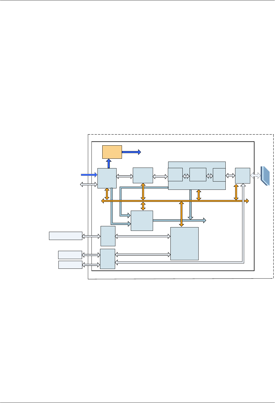
Block Diagram
Figure 3-1 Block diagram of RTN 360
USB flash drive or
Wi-Fi module
System
control unit
Power
unit
Clock unit
Provides
clock signal
to other units.
Panel
antenna
Ethernet
switching
unit
Ethernet
access
unit
RF
proces
sing
unit
Clock
signal
PoE signal
Provides power to other
units.
SHUA2
MUX
unit
Modem
unit
Baseband processing unit
Control
signal
RSSI port
RSSI test level
signal
OptiX RTN 360
NMS port
GE signal GE signal
USB
port
-48 V
RJ45
port
TDD
unit
FE/GE signal
OptiX RTN 360 Radio Transmission System
Product Description 3 Product Structure
Issue 01 (2016-01-15) Huawei Proprietary and Confidential
Copyright © Huawei Technologies Co., Ltd.
32

Functional Units
Table 3-1 Functional units
Functional Unit Description
Ethernet access unit lReceives/Transmits one channel of
Ethernet service signals and one channel
of PoE signals.
lSplits PoE signals into -48 V power
signals and FE/GE signals.
lTransmits the power signals to the power
unit.
lConverts serial Ethernet signals into
parallel Ethernet signals.
lPerforms frame delimitation, preamble
stripping, and cyclic redundancy checks
(CRCs).
Ethernet switching unit lProcesses VLAN tags in Ethernet service
signals.
lPerforms quality of service (QoS)
processing for Ethernet frames.
lGrooms services and processes
protocols.
Baseband processing unit lMaps and demaps service signals to/
from microwave frame signals.
lProcesses overhead bytes in microwave
frames.
lPerforms forward error correction (FEC)
coding and decoding.
lModulates and demodulates digital
signals.
lConverts between analog and digital
signals.
lUses the TDD unit to control signal
receiving/transmitting according to the
specified ratio of receive/transmit
timeslots.
RF processing unit lPerforms frequency conversion and
power amplification, and sends RF
signals to antennas in the transmit
direction.
lPerforms isolation, filtering, down-
conversion, and power amplification for
RF signals, and converts RF signals into
low-frequency analog signals in the
receive direction.
OptiX RTN 360 Radio Transmission System
Product Description 3 Product Structure
Issue 01 (2016-01-15) Huawei Proprietary and Confidential
Copyright © Huawei Technologies Co., Ltd.
33
Functional Unit Description
Antenna Performs conversion between RF signals
and electromagnetic waves.
System control unit lConfigures and manages the system.
lCollects alarms and monitors
performance.
lProcesses signals to and from the USB
port.
lProcesses Wi-Fi connection signals.
Clock unit lTraces the specified clock source signals.
lProvides clock signals required by the
system.
Power unit lProcesses power over Ethernet signals.
lPerforms DC/DC conversion and
provides power signals to other units.
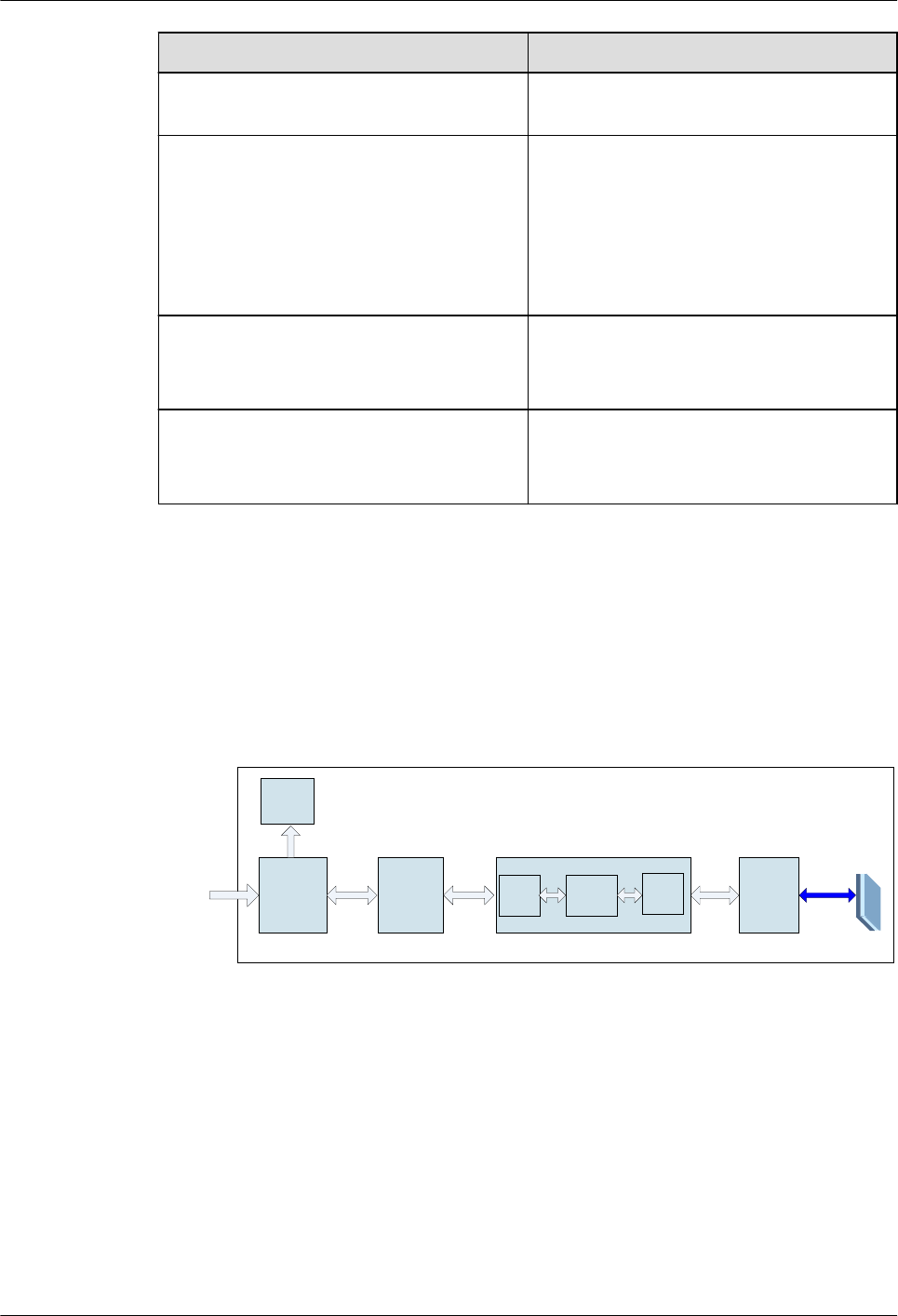
3.2 Service Signal Processing Flow
This section describes how the functional units of RTN 360 process power over Ethernet
(PoE) signals.
Figure 3-2 Signal processing flow
Ethernet
access unit
RF
processing
unit
Ethernet
switching unit
PoE signal
Service bus Service bus Modulated
signal RF signal
OptiX RTN 360
MUX
unit
Modem
unit
Baseband processing unit
TDD
unit
–48 V
Power unit
OptiX RTN 360 Radio Transmission System
Product Description 3 Product Structure
Issue 01 (2016-01-15) Huawei Proprietary and Confidential
Copyright © Huawei Technologies Co., Ltd.
34

Table 3-2 Signal processing in the transmit direction
St
ep
Functional Unit Processing Flow
1 Ethernet access unit lReceives PoE signals.
lSplits PoE signals into Ethernet service signals and -48 V
power signals.
lTransmits the power signals to the power unit.
lExtracts Ethernet frames from Ethernet service signals.
2 Ethernet switching
unit
lPerforms Layer 2 protocol processing and quality of
service (QoS) processing for the Ethernet frames.
lTransmits processed Ethernet service signals to the
baseband processing unit.
3 Baseband processing
unit
lReceives Ethernet service signals from the Ethernet
switching unit.
lCombines Ethernet service signals and microwave frame
overheads into microwave frames.
lPerforms forward error correction (FEC) coding.
lSelects a proper modulation scheme based on the current
channel quality.
lPerforms modulation and converts digital signals to
analog signals.
lTransmits the modulated signals to the RF processing
unit using the transmit timeslot specified by the TDD
electronic switch.
4 RF processing unit lPerforms up-conversion and power amplification to
convert the modulated signals into RF signals.
lTransmits the RF signals to the antenna through a
flexible waveguide.
Table 3-3 Signal processing in the receive direction
St
ep
Functional Unit Processing Flow
1 RF processing unit lIsolates and filters RF signals.
lPerforms down-conversion and power amplification.
lTransmits the modulated signals to the baseband
processing unit.
OptiX RTN 360 Radio Transmission System
Product Description 3 Product Structure
Issue 01 (2016-01-15) Huawei Proprietary and Confidential
Copyright © Huawei Technologies Co., Ltd.
35

St
ep
Functional Unit Processing Flow
2 Baseband processing
unit
lReceives modulated signals from the RF processing unit
using the receive timeslot specified by the TDD
electronic switch.
lConverts analog signals to digital signals.
lDemodulates signals.
lPerforms FEC decoding.
lExtracts overhead signals and Ethernet frames from
microwave frames.
lTransmits the Ethernet frames to the Ethernet switching
unit.
3 Ethernet switching
unit
lReceives Ethernet frames from the baseband processing
unit.
lProcesses the Ethernet frames based on service
configurations and Layer 2 protocols.
lTransmits the Ethernet frames to the Ethernet access
unit.
4 Ethernet access unit Converts parallel Ethernet signals to serial Ethernet signals
and transmits them.
3.3 Ports
An RTN 360 has one GE port, one P&E port, and one maintenance compartment.
OptiX RTN 360 Radio Transmission System
Product Description 3 Product Structure
Issue 01 (2016-01-15) Huawei Proprietary and Confidential
Copyright © Huawei Technologies Co., Ltd.
36
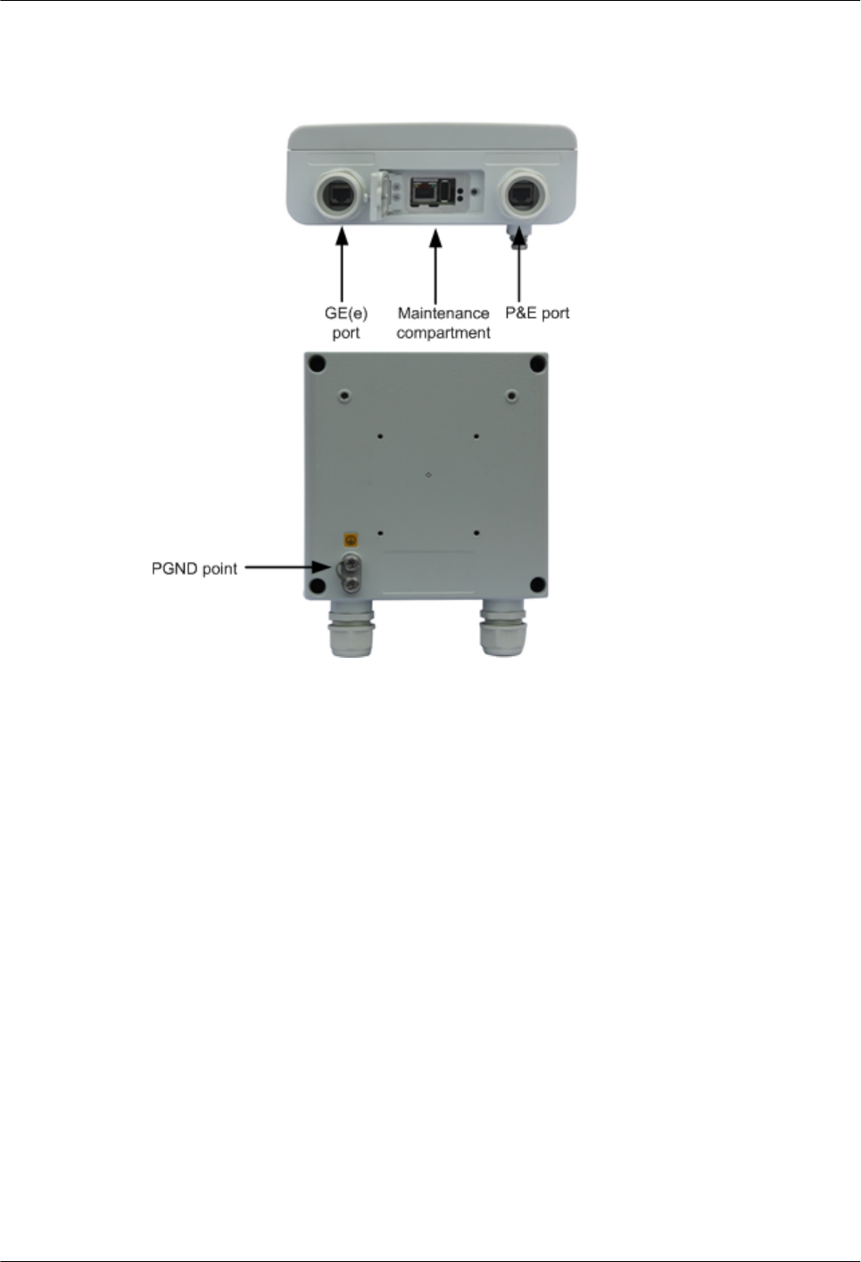
Port Positions
Figure 3-3 Port positions
The maintenance compartment contains a USB port, RSSI port, and an NMS port. See Figure
3-4. When RTN 360 is running, the protective cover of the maintenance compartment must be
closed.
OptiX RTN 360 Radio Transmission System
Product Description 3 Product Structure
Issue 01 (2016-01-15) Huawei Proprietary and Confidential
Copyright © Huawei Technologies Co., Ltd.
37
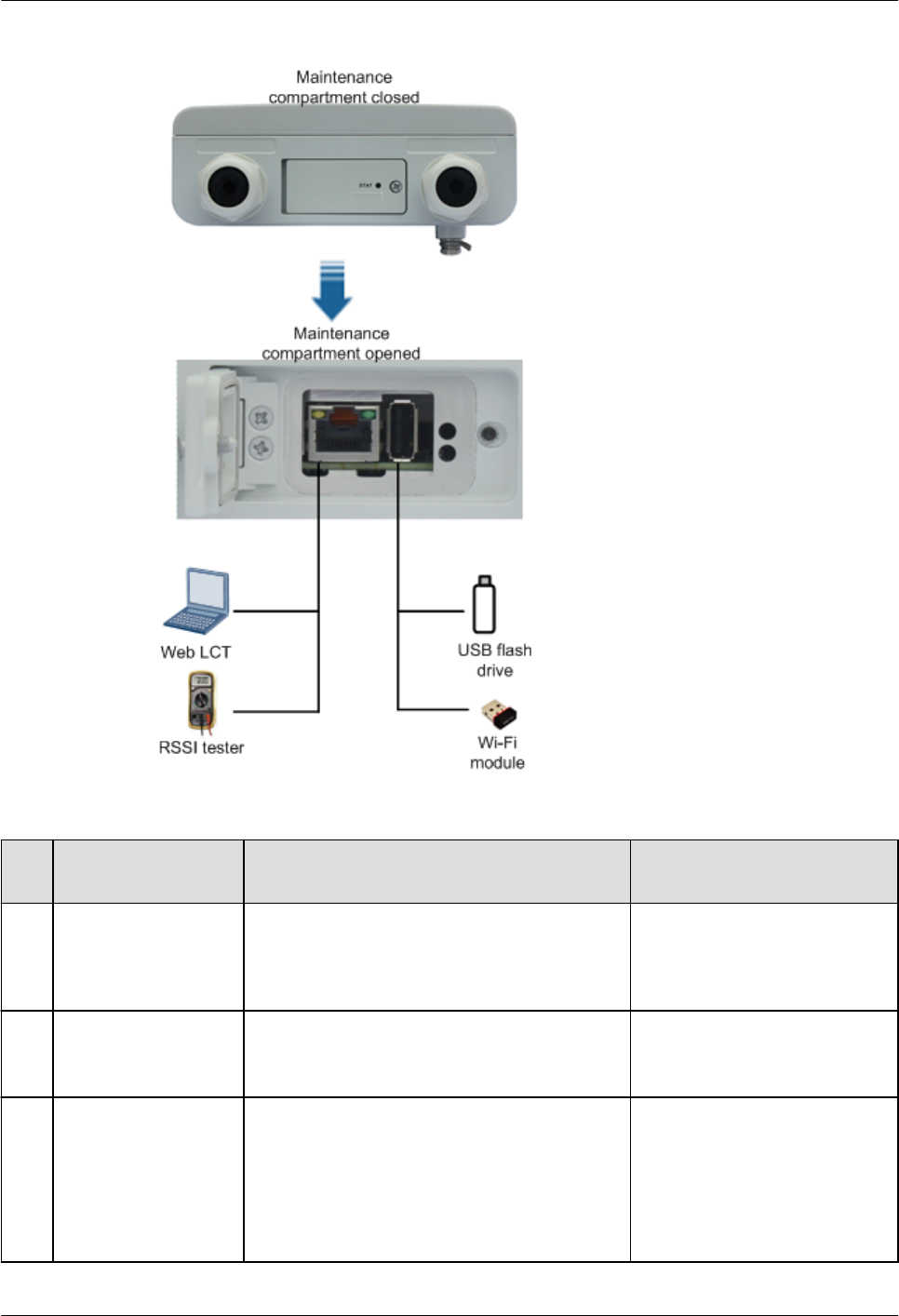
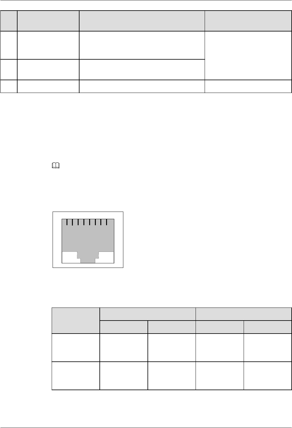
Figure 3-4 Front view of the management ports
Table 3-4 Ports
No
.
Port Description Connector Type
1 GE(e) GE electrical port
NOTE
Do not remove the protective connector of a vacant
GE electrical port.
RJ45 connector
2 P&E Power over Ethernet port, which can
concurrently receive FE/GE electrical signals
and -48 V power signals
RJ45 connector
3 USB port lA USB flash drive can connect to the USB
port to import initial configuration data,
back up NE data, or upgrade software.
lA Wi-Fi module can connect to the USB
port to enable connection of the Mobile
LCT or Web LCT to the equipment.
USB connector
OptiX RTN 360 Radio Transmission System
Product Description 3 Product Structure
Issue 01 (2016-01-15) Huawei Proprietary and Confidential
Copyright © Huawei Technologies Co., Ltd.
38
No
.
Port Description Connector Type
4 RSSI port You can obtain the received signal level (RSL)
of an RTN 360 by testing the voltage at the
RSSI port using a multimeter.
RJ45 connector
NOTE
RSSI port and NMS port share an
RJ45 connector.
5 NMS port The NMS port transmits network management
signals.
6 PGND point - M5 screw
P&E Port and GE(e) Port
The P&E port can simultaneously receive GE electrical signals and -48 V power signals. It
connects to a power injector (PI), a Dock, or power sourcing equipment (PSE).
The GE(e) port is a common GE electrical port.
NOTE
On the NMS, the P&E port is displayed as GE1 and the GE(e) port is displayed as GE2.
Both the P&E and GE(e) ports use RJ45 connectors.
Figure 3-5 Front view of an RJ45 connector
123 4 5 6 7 8
Table 3-5 Pin assignments for RJ45 connectors of the P&E and GE(e) ports
Pin No. P&E Port GE(e) Port
Signal Function Signal Function
1 BIDA+/BGND Bidirectional
data wire A (+)/
BGND
BIDA+ Bidirectional
data wire A (+)
2 BIDA-/BGND Bidirectional
data wire A (-)/
BGND
BIDA- Bidirectional
data wire A (-)
OptiX RTN 360 Radio Transmission System
Product Description 3 Product Structure
Issue 01 (2016-01-15) Huawei Proprietary and Confidential
Copyright © Huawei Technologies Co., Ltd.
39

Pin No. P&E Port GE(e) Port
Signal Function Signal Function
3 BIDB+/-48 V Bidirectional
data wire B
(+)/-48 V
BIDB+ Bidirectional
data wire B (+)
4 BIDB-/BGND Bidirectional
data wire B (-)/
BGND
BIDB- Bidirectional
data wire B (-)
5 BIDC+/BGND Bidirectional
data wire C (+)/
BGND
BIDC+ Bidirectional
data wire C (+)
6 BIDC-/-48 V Bidirectional
data wire C
(-)/-48 V
BIDC- Bidirectional
data wire C (-)
7 BIDD+/-48 V Bidirectional
data wire D
(+)/-48 V
BIDD+ Bidirectional
data wire D (+)
8 BIDD-/-48 V Bidirectional
data wire D
(-)/-48 V
BIDD- Bidirectional
data wire D (-)
USB Port
The USB port can either connect to a USB flash drive for importing configurations, upgrading
software, or backing up data or to a Wi-Fi module for enabling connection of the Mobile LCT
or Web LCT to the equipment.
RSSI Port/NMS Port
Table 3-6 provides the pin assignments for the RJ45 connector of the RSSI port/NMS port.
Table 3-6 Pin assignments for the RJ45 connector of the RSSI port/NMS port
Pin No. Signal
1 Signal output (+)
2 Signal output (-)
3 Signal input (+)
4 Ground
5 Reserved
6 Signal input (-)
OptiX RTN 360 Radio Transmission System
Product Description 3 Product Structure
Issue 01 (2016-01-15) Huawei Proprietary and Confidential
Copyright © Huawei Technologies Co., Ltd.
40

Pin No. Signal
7 RSSI test level signal
8 Reserved
The RJ45 connector has two indicators that indicate the NMS port connection status. Table
3-7 describes what the indicator statuses mean.
Table 3-7 Indicator status explanation
Indicator Status Meaning
LINK (yellow) On The NMS port connection is normal.
Off The NMS port connection is
interrupted.
ACT (green) On or blinks The NMS port is receiving or
transmitting data.
Off The NMS port is not receiving or
transmitting data.
3.4 Indicators
RTN 360 has an STAT indicator and a USB port indicator.
The two indicators are in the maintenance compartment. You can observe the STAT indicator
even when the protective cover of the maintenance compartment is closed, but you can
observe the USB port indicator only if the protective cover of the maintenance compartment
is open.
OptiX RTN 360 Radio Transmission System
Product Description 3 Product Structure
Issue 01 (2016-01-15) Huawei Proprietary and Confidential
Copyright © Huawei Technologies Co., Ltd.
41
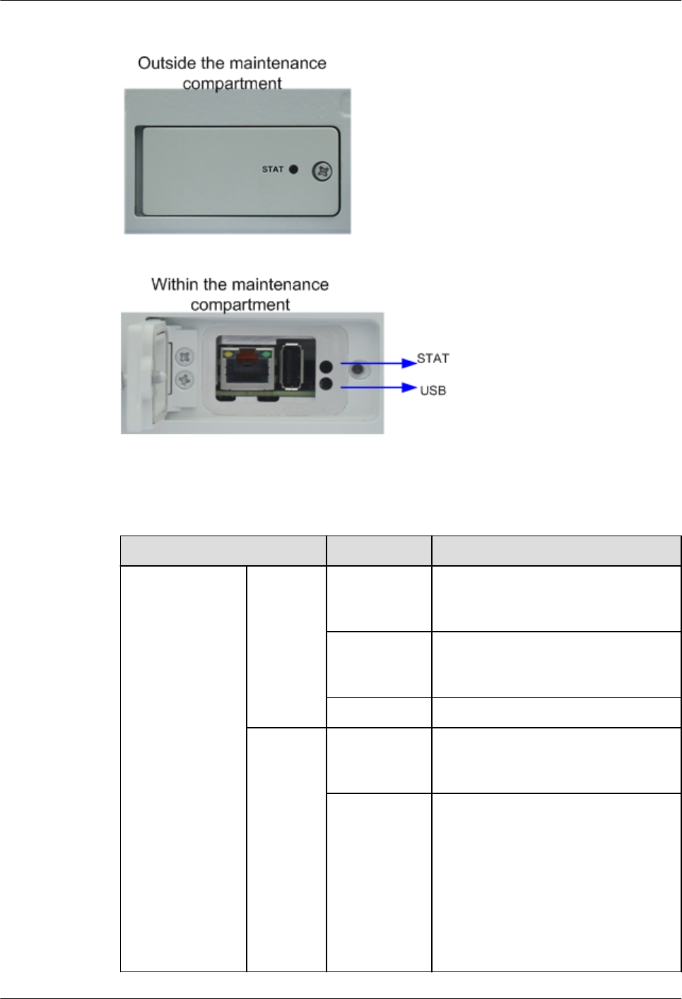
Figure 3-6 Indicator positions
Table 3-8 Indicator status explanation
Indicator Status Meaning
Indicator that
indicates system
operating status
and link status
(STAT)
Operating
status
Steady green The equipment is working properly
and services at the air interface are
normal.
Steady red The hardware is faulty (for example,
the equipment fails to start, or a
HARD_BAD alarm is reported).
Off The equipment is not powered on.
Link
status
Blinks red The equipment is working properly but
services at the air interface are
interrupted.
Steady green lThe microwave link is available.
No expected receive power is set
according to the network plan.
lThe microwave link is available.
The expected receive power is set
according to the network plan. The
difference between the actual
receive power and the expected
receive power is less than 3 dB.
OptiX RTN 360 Radio Transmission System
Product Description 3 Product Structure
Issue 01 (2016-01-15) Huawei Proprietary and Confidential
Copyright © Huawei Technologies Co., Ltd.
42

Indicator Status Meaning
Blinks green The microwave link is available. The
difference between the actual receive
power and the expected receive power
is greater than 3 dB.
USB port
indicator
Wi-Fi
module
Steady green The Wi-Fi module has been identified
and is working properly.
Steady red The Wi-Fi module is faulty.
Off lNo Wi-Fi module is connected to
the USB port.
lThe Wi-Fi module connected to the
USB port cannot be identified.
USB flash
drive
Steady green Backing up or restoring data is
complete.
Blinks green Data is being backed up or restored.
Steady red lThe USB flash drive is faulty.
lBacking up or restoring data fails.
Blinks red The hardware is faulty and fails to
initialize the USB flash drive.
Off lNo USB flash drive is connected to
the USB port.
lThe USB flash drive connected to
the USB port cannot be identified.
NOTE
After you load data to an RTN 360 using a USB flash drive, the RTN 360 automatically resets. All the
indicators are off during the reset. After the reset is complete, observe the STAT indicator to learn about the
status of the RTN 360.
3.5 Labels
A product nameplate label, electrostatic discharge (ESD) warning label, radiation warning
label, grounding label, and high temperature warning label are affixed on a chassis. Adhere to
any warnings on the labels when performing tasks to avoid personal injury and damage to
equipment.
OptiX RTN 360 Radio Transmission System
Product Description 3 Product Structure
Issue 01 (2016-01-15) Huawei Proprietary and Confidential
Copyright © Huawei Technologies Co., Ltd.
43
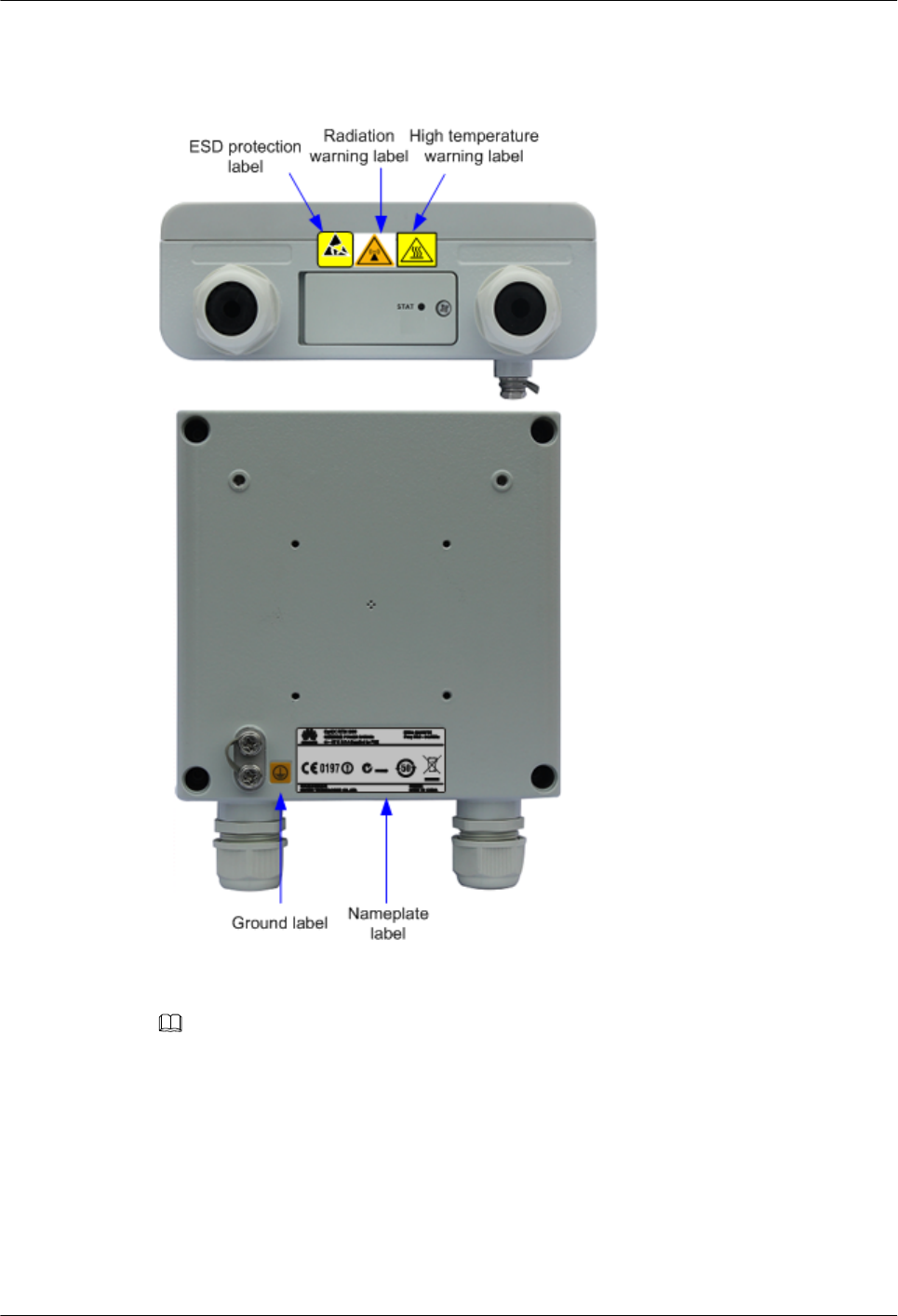
Label Positions
Figure 3-7 Label positions
NOTE
High temperature warning label: Indicates that the equipment surface temperature may exceed 70°C
when the ambient temperature is higher than 55°C. Wear protective gloves to handle the equipment.
OptiX RTN 360 Radio Transmission System
Product Description 3 Product Structure
Issue 01 (2016-01-15) Huawei Proprietary and Confidential
Copyright © Huawei Technologies Co., Ltd.
44

Product Nameplate Label
Figure 3-8 Product nameplate label
Table 3-9 Product nameplate label description
Label Information Description
OptiX RTN 360 Indicates the product name.
ITEM: 52450775 Indicates the product item for identifying
the product model.
-48V; 0.5A Indicates the power supply rated value.
Supplied by P&E Indicates that PoE is used.
Freq: 59.0–64.0 GHz Indicates the frequency range.
OptiX RTN 360 Radio Transmission System
Product Description 3 Product Structure
Issue 01 (2016-01-15) Huawei Proprietary and Confidential
Copyright © Huawei Technologies Co., Ltd.
45

4 Network Management System
About This Chapter
This chapter describes network management solutions and the network management system
(NMS) software used in these solutions.
4.1 Network Management Solutions
Huawei provides complete transport network management solutions that satisfy the
telecommunications management network (TMN) requirements for various function domains
and customer groups of telecommunications networks.
4.2 Web LCT
The Web LCT is a local maintenance terminal running on a PC.
4.3 Mobile LCT
The Mobile LCT is a local maintenance terminal running on a smartphone.
4.4 U2000-T
The iManager U2000-T is a network-level management system (NMS) that manages Huawei
fixed-line network products in a unified manner.
4.5 U2000-M
The U2000-M is a network-level management system that manages Huawei mobile
communications products in a unified manner.
OptiX RTN 360 Radio Transmission System
Product Description 4 Network Management System
Issue 01 (2016-01-15) Huawei Proprietary and Confidential
Copyright © Huawei Technologies Co., Ltd.
46
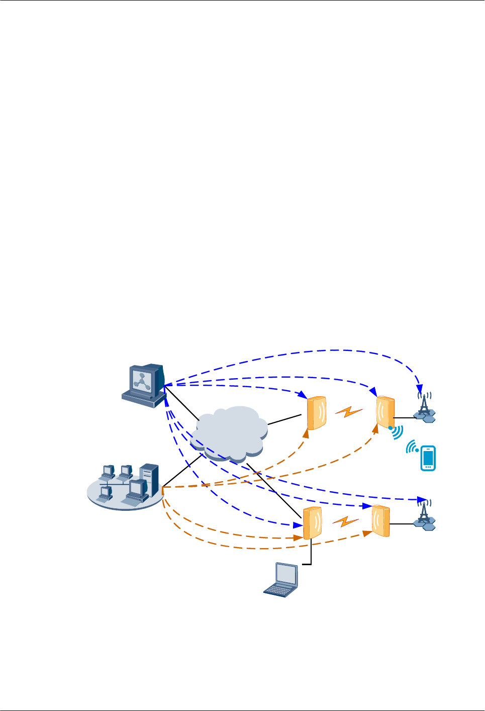
4.1 Network Management Solutions
Huawei provides complete transport network management solutions that satisfy the
telecommunications management network (TMN) requirements for various function domains
and customer groups of telecommunications networks.
The following network management solutions are available:
liManager U2000 Web LCT local maintenance terminal
The Web LCT, a web-based local maintenance terminal, manages local and remote NEs
on a per-NE/hop basis.
liManager U2000 Mobile LCT local maintenance terminal
The Mobile LCT, a local maintenance terminal running on a smartphone, manages local
and remote NEs on a per-NE/hop basis through Wi-Fi.
liManager U2000-T unified network management system
The iManager U2000-T, a network-level management system, manages Huawei RTN,
PTN, MSTP, and WDM products on transport networks in a unified manner.
liManager U2000-M unified network management system
The iManager U2000-M, a network-level management system, manages Huawei mobile
communications products in a unified manner.
Figure 4-1 Network management solutions for transport networks
WAN/LAN
V-Band
V-Band
V-Band
V-Band
WebLCT
U2000-M
U2000-T
Mobile LCT
OptiX RTN 360 Radio Transmission System
Product Description 4 Network Management System
Issue 01 (2016-01-15) Huawei Proprietary and Confidential
Copyright © Huawei Technologies Co., Ltd.
47
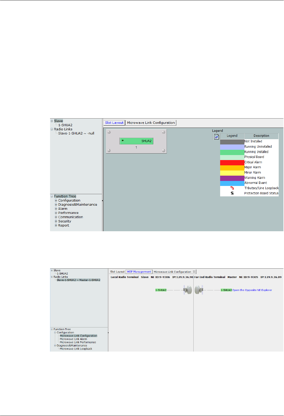
4.2 Web LCT
The Web LCT is a local maintenance terminal running on a PC.
The Web LCT provides the following management functions at the NE layer: NE
management, alarm management, performance management, configuration management,
communication management, and security management.
The Web LCT also provides hop management, which displays the information about the two
ends of a microwave link hop graphically and enables a microwave link hop to be managed
easily.
Figure 4-2 NE management window
Figure 4-3 HOP management window
4.3 Mobile LCT
The Mobile LCT is a local maintenance terminal running on a smartphone.
OptiX RTN 360 Radio Transmission System
Product Description 4 Network Management System
Issue 01 (2016-01-15) Huawei Proprietary and Confidential
Copyright © Huawei Technologies Co., Ltd.
48
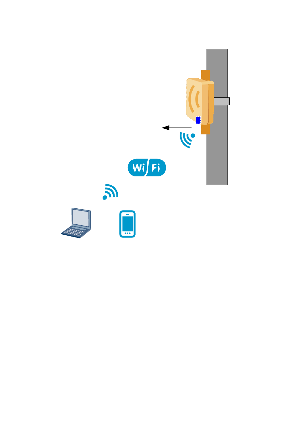
The Mobile LCT manages an NE after connecting to the NE using Wi-Fi. Figure 4-4 shows a
typical application scenario.
Figure 4-4 Mobile LCT application scenario
Wi-Fi module
Mobile LCT
Web LCT
or
The Mobile LCT can create NEs by searching NEs, configure NE attributes, microwave links,
and DCN, and query alarms.
4.4 U2000-T
The iManager U2000-T is a network-level management system (NMS) that manages Huawei
fixed-line network products in a unified manner.
The U2000-T provides topology management, which displays NE positions and connections
between NEs. See Figure 4-5.
The U2000-T manages network-level alarms, performance, inventory, and security, and end-
to-end service configurations. See Figure 4-6.
The U2000-T provides a built-in NE Explorer to manage all NEs on the topology. See Figure
4-7.
OptiX RTN 360 Radio Transmission System
Product Description 4 Network Management System
Issue 01 (2016-01-15) Huawei Proprietary and Confidential
Copyright © Huawei Technologies Co., Ltd.
49
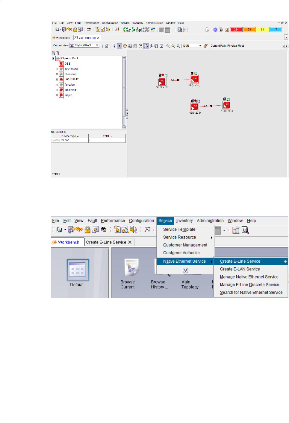
Figure 4-5 Topology management interface of the U2000-T
Figure 4-6 End-to-end service configuration interface of the U2000-T
OptiX RTN 360 Radio Transmission System
Product Description 4 Network Management System
Issue 01 (2016-01-15) Huawei Proprietary and Confidential
Copyright © Huawei Technologies Co., Ltd.
50
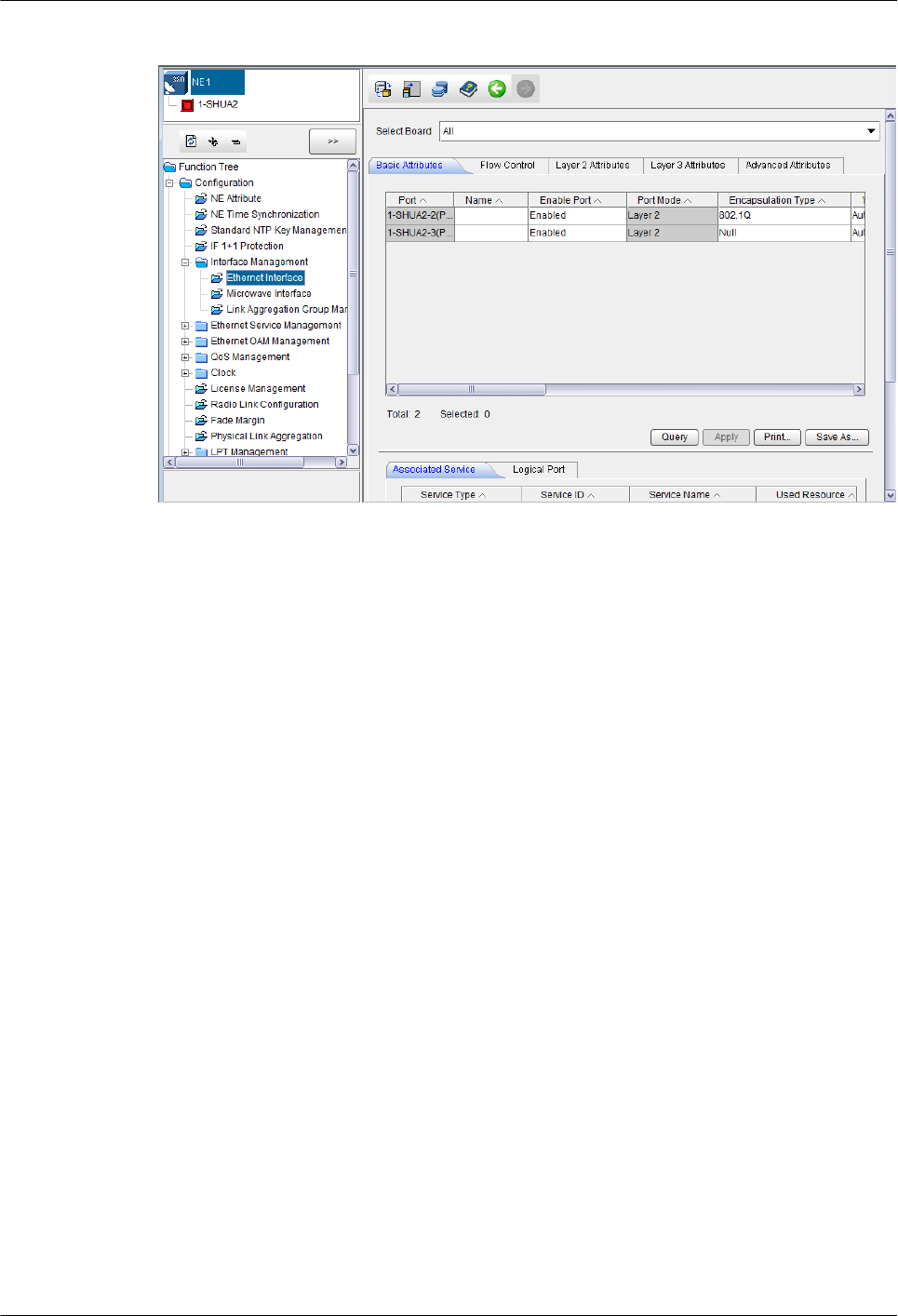
Figure 4-7 NE Explorer interface of the U2000-T
4.5 U2000-M
The U2000-M is a network-level management system that manages Huawei mobile
communications products in a unified manner.
The U2000-M displays connections between RTN 360s and base stations.
The U2000-M can manage RTN 360s using its built-in NE Explorer.
OptiX RTN 360 Radio Transmission System
Product Description 4 Network Management System
Issue 01 (2016-01-15) Huawei Proprietary and Confidential
Copyright © Huawei Technologies Co., Ltd.
51

5 Technical Specifications
About This Chapter
This chapter describes the technical specifications of OptiX RTN 360.
5.1 Ethernet Service Specifications
This section describes the service throughput for Native Ethernet services on a hop of
microwave link.
5.2 RF Performance
This section describes major RF performance of RTN 360, including the frequency band,
transmit power, and receiver sensitivity.
5.3 Antenna Performance
This section describes the major antenna performance of RTN 360, including the antenna
gain, standing wave ratio (SWR), and cross polarization discrimination (XPD).
5.4 Predicted Reliability
This section describes the predicted equipment reliability of a single RTN 360 and the
predicted link reliability of a hop of microwave link forming by two RTN 360s.
5.5 Integrated System Performance
Integrated system performance includes the dimensions, weight, power consumption, and
power supply.
OptiX RTN 360 Radio Transmission System
Product Description 5 Technical Specifications
Issue 01 (2016-01-15) Huawei Proprietary and Confidential
Copyright © Huawei Technologies Co., Ltd.
52

5.1 Ethernet Service Specifications
This section describes the service throughput for Native Ethernet services on a hop of
microwave link.
The bit error performance of Ethernet services on RTN 360 complies with IETF RFC2544.
Throughput of Ethernet Services
Table 5-1 Throughput of Ethernet Services
Radio working
modes
(Modulation
Scheme / Channel
Spacing)
Ratio of Timeslots
for Uplink Data to
Those for
Downlink Data
(Uplink:Downlin
k)
Uplink
Throughput
(Mbit/s)
Downlink
Throughput
(Mbit/s)
QPSK/200MHz 1:1 129 to 165 129 to 165
1:2 85 to 109 176 to 225
2:1 176 to 225 85 to 109
1:3 62 to 80 198 to 254
3:1 198 to 254 62 to 80
1:4 46 to 59 214 to 274
4:1 214 to 274 46 to 59
1:5 39 to 50 221 to 284
5:1 221 to 284 39 to 50
16QAM/200MHz 1:1 262 to 336 262 to 336
1:2 173 to 221 355 to 455
2:1 355 to 455 173 to 221
1:3 126 to 162 403 to 516
3:1 403 to 516 126 to 162
1:4 97 to 125 430 to 550
4:1 430 to 550 97 to 125
1:5 79 to 101 449 to 576
5:1 449 to 576 79 to 101
32QAM/200MHz 1:1 329 to 422 329 to 422
1:2 216 to 277 445 to 570
OptiX RTN 360 Radio Transmission System
Product Description 5 Technical Specifications
Issue 01 (2016-01-15) Huawei Proprietary and Confidential
Copyright © Huawei Technologies Co., Ltd.
53

Radio working
modes
(Modulation
Scheme / Channel
Spacing)
Ratio of Timeslots
for Uplink Data to
Those for
Downlink Data
(Uplink:Downlin
k)
Uplink
Throughput
(Mbit/s)
Downlink
Throughput
(Mbit/s)
2:1 445 to 570 216 to 277
1:3 156 to 200 506 to 648
3:1 506 to 648 156 to 200
1:4 122 to 157 538 to 688
4:1 538 to 688 122 to 157
1:5 99 to 127 562 to 719
5:1 562 to 719 99 to 127
NOTE
The throughput is measured assuming that untagged Ethernet frames with length ranging from 64 bytes
to 9600 bytes are transmitted.
5.2 RF Performance
This section describes major RF performance of RTN 360, including the frequency band,
transmit power, and receiver sensitivity.
Table 5-2 RF performance
Item Performance
Working mode l200MHz/QPSK
l200MHz/16QAM
l200MHz/32QAM
Operating frequency band 59 GHz to 64 GHz
Transmit power lQPSK: 5dBm
l16QAM: 3dBm
l32QAM: 1dBm
Receive power -23 dBm
Receiver Sensitivity (BER = 10-6) l200MHz/QPSK: -68dBm
l200MHz/16QAM: -60dBm
l200MHz/32QAM: -57dBm
OptiX RTN 360 Radio Transmission System
Product Description 5 Technical Specifications
Issue 01 (2016-01-15) Huawei Proprietary and Confidential
Copyright © Huawei Technologies Co., Ltd.
54

Item Performance
Ratio of timeslots for uplink data to those
for downlink data
5:1, 4:1, 3:1, 2:1, 1:1, 1:2, 1:3, 1:4 and 1:5
5.3 Antenna Performance
This section describes the major antenna performance of RTN 360, including the antenna
gain, standing wave ratio (SWR), and cross polarization discrimination (XPD).
Table 5-3 Antenna performance
Item Performance
Antenna gain 34.5 dBi
SWR 10 dB
3 dB beamwidth 1.9º
XPD 21 dB
Front-to-back ratio (FBR) > 48 dB
Regulatory compliance ETSI class 2
5.4 Predicted Reliability
This section describes the predicted equipment reliability of a single RTN 360 and the
predicted link reliability of a hop of microwave link forming by two RTN 360s.
Predicted Equipment Reliability
The equipment reliability shows the reliability of a single piece of equipment.
Table 5-4 Predicted equipment reliability
Item Performance
MTBF (hour) 66.22 x 10⁴
MTBF (year) 75.59
MTTR (hour) 0.79
Availability 99.99985%
OptiX RTN 360 Radio Transmission System
Product Description 5 Technical Specifications
Issue 01 (2016-01-15) Huawei Proprietary and Confidential
Copyright © Huawei Technologies Co., Ltd.
55

Predicted Link Reliability
The link reliability shows the reliability of a microwave link hop and all components
involved.
Table 5-5 Predicted link reliability
Item Performance
MTBF (hour) 33.11 x 10⁴
MTBF (year) 37.79
Availability 99.99970%
5.5 Integrated System Performance
Integrated system performance includes the dimensions, weight, power consumption, and
power supply.
Mechanical Performance and Power Consumption
Item Performance
Dimensions (H x W x D) 192.5 mm x 192.5 mm x 70 mm
Weight 2.5 kg
Typical power consumption 20 W
Power supply lSupports power over Ethernet.
lThe input PoE voltage ranges from –
38.4 V to –57.6 V.
Electromagnetic Compatibility
lPassed CE authentication
lCompliant with ETSI EN 301 489-1
lCompliant with ETSI EN 301 489-4
lCompliant with EN 55022 class B
Lightning Protection
lCompliant with ITU-T K.20
lCompliant with ITU-T K.21
lCompliant with ITU-T K.27
lCompliant with ETSI EN 300 253.
OptiX RTN 360 Radio Transmission System
Product Description 5 Technical Specifications
Issue 01 (2016-01-15) Huawei Proprietary and Confidential
Copyright © Huawei Technologies Co., Ltd.
56

Safety
lPassed CE authentication
lCompliant with IEC 60825
lCompliant with IEC 60215
lCompliant with IEC 60950-1
lCompliant with IEC 60950-22
lCompliant with K.20
lCompliant with K.21
lCompliant with GB 12638-1990
lCompliant with EN 41003
Environment
RTN 360 is used outdoors.
Table 5-6 Environment performance
Item Performance
Major
reference
standards
Operating Compliant with EN 300 019-2-4
Transport
ation
Compliant with EN 300 019-2-3 class 2.3
Storage Compliant with EN 300 019-2-4
Temperature Operating -33ºC to +55ºC
Transport
ation and
storage
-40ºC to +70ºC
Protection class IP65
Relative humidity 5% to 100%
Earthquake resistant design Compliant with ETSI 300 019-2-4
Mechanical stress Compliant with ETSI EN 300 019-2-1
OptiX RTN 360 Radio Transmission System
Product Description 5 Technical Specifications
Issue 01 (2016-01-15) Huawei Proprietary and Confidential
Copyright © Huawei Technologies Co., Ltd.
57

6 Accessories
About This Chapter
This chapter describes all RTN 360 accessories.
6.1 Power Injector
A power injector (PI) uses DC or AC input power. It transmits both GE service signals and
-48 V power signals to an RTN 360 through an Ethernet cable.
6.2 USB Flash Drives
Configuring, replacing, and upgrading RTN 360s is simple with USB flash drives, which store
NE data and new software to be installed and are also used to back up configuration data.
6.3 Wi-Fi Module
A Wi-Fi module for an RTN 360 enables the Mobile LCT or Web LCT to connect to the RTN
360 using Wi-Fi, implementing contact-free configuration and maintenance.
OptiX RTN 360 Radio Transmission System
Product Description 6 Accessories
Issue 01 (2016-01-15) Huawei Proprietary and Confidential
Copyright © Huawei Technologies Co., Ltd.
58
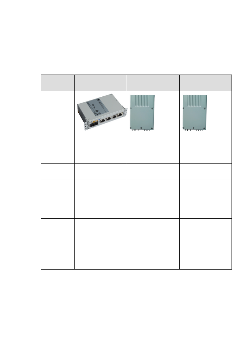
6.1 Power Injector
A power injector (PI) uses DC or AC input power. It transmits both GE service signals and
-48 V power signals to an RTN 360 through an Ethernet cable.
The RTN 360 can work with three models of Huawei PIs. Table 6-1 lists the differences
among the three models.
Table 6-1 PI differences
Model OptiX RTN PI-DC
A11
OptiX RTN PI-DC
B20
OptiX RTN PI-AC
B20
Appearance
Application
scenario
Equipment room or
outdoor cabinet
Outdoor (A PI should
not be installed at a
high position on a
tower.)
Outdoor (A PI should
not be installed at a
high position on a
tower.)
Dimensions
(H x W x D)
36 mm x 145.6 mm x
84 mm
250 mm x 180 mm x
52 mm
250 mm x 180 mm x
52 mm
Weight 0.5 kg 3.0 kg 3.0 kg
Power input DC power: –38.4 V
to –57.6 V
DC power: –38.4 V
to –57.6 V
AC power: 90 V to
264 V, with the
frequency ranging
from 45 Hz to 65 Hz
P&E port
count and
mode
One P&E port, PSE-
based power support or
forcible power supply
Two P&E ports, PSE-
based power support or
forcible power supply
Two P&E ports, PSE-
based power support or
forcible power supply
DC output
port
Not supported One DC output port.
Switching between DC
output and PoE output
is supported.
One DC output port.
Switching between DC
output and PoE output
is supported.
For details about each model of PI, see the corresponding product description and installation
guide.
6.2 USB Flash Drives
Configuring, replacing, and upgrading RTN 360s is simple with USB flash drives, which store
NE data and new software to be installed and are also used to back up configuration data.
OptiX RTN 360 Radio Transmission System
Product Description 6 Accessories
Issue 01 (2016-01-15) Huawei Proprietary and Confidential
Copyright © Huawei Technologies Co., Ltd.
59

Functions and Features
USB flash drives prepared for RTN 360s store NE software and configuration data (including
databases, system parameters, and scripts).
lEquipment software and scripts stored in USB flash drives are installed on RTN 360s for
deployment and commissioning. With this system, users do not need to configure data
onsite.
lSoftware, patch packages, NE databases, and system parameters are backed up to USB
flash drives. This avoids the need to reconfigure data when replacing a RTN 360.
lSoftware of target versions stored in USB flash drives is imported to RTN 360s.
lSecurity features:
–The administrator accounts and passwords (encrypted) in the RTN.CER or
RTNEXTRA.CER file are used to authenticate USB flash drives.
–Other files in USB flash drives can be encrypted.
–The validity of files in USB flash drives can be verified.
Application Scenario
lFor deployment and commissioning of an RTN 360, scripts, and software are stored on a
USB flash drive. After the USB flash drive is plugged in and functioning, the RTN 360
downloads software, and scripts in sequence.
lFor an upgrade or downgrade of an RTN 360, only the software of the target version is
stored on a USB flash drive. After the USB flash drive is plugged in and functioning, the
RTN 360 compares the versions of the running software and the software stored on the
USB flash drive. If the versions are not the same, the RTN 360 automatically downloads
the software from the USB flash drive for an upgrade or downgrade.
lDuring RTN 360 replacement, an empty USB flash drive is inserted into a faulty device,
which automatically backs up its data to the drive. After the faulty device is replaced, the
drive holding the backup data is inserted into the new device, which automatically
downloads the backup NE data, software, and system parameters and restores the NE
data.
Data uploading
A USB flash drive contains the following folders:
NOTE
The USB flash drive partition format is FAT32.
lThe root directory stores an RTN.CER/RTNEXTRA.CER file and a USBSEC.CFG
file (security policy file).
NOTE
lThe RTN.CER/RTNEXTRA.CER file, which stores administrator-level account and
password information (with password information encrypted), is used for authenticating the
USB flash drive. The file is generated by a system administrator at the network management
center (NMC) using a dedicated tool.
lThe USBSEC.CFG file stores the list of available files in the USB flash drive and the
verification information and encryption parameters of each file. When the files in the USB
flash drive are being loaded to an NE, the NE verifies and decrypts the files based on the
USBSEC.CFG file. If a file is not in the file list in the USBSEC.CFG file or a file fails to be
verified or decrypted, the file cannot be used by the NE.
lpkg: stores the NE software.
OptiX RTN 360 Radio Transmission System
Product Description 6 Accessories
Issue 01 (2016-01-15) Huawei Proprietary and Confidential
Copyright © Huawei Technologies Co., Ltd.
60

NOTICE
Data is saved in the \pkg folder only when the NE software is upgraded. Otherwise, keep
the folder empty.
lpatch: stores the patch software.
lsysdata: stores system parameters.
lscript: stores scripts.
ldb: stores NE databases.
llicense: stores a license.
NOTE
The license directory cannot be backed up or restored. It is usually empty.
ldevicetype: stores device type parameters.
When a USB flash drive is connected to an RTN 360, the RTN 360 checks the folders on the
USB flash drive in the following order:
1. Checks for the RTN.CER or RTNEXTRA.CER file in the root directory. If the file
exists, the USB flash drive is authenticated. Otherwise, the USB flash drive fails to be
identified.
2. Checks the USBSEC.CFG file in the root directory, and verifies the integrity of files in
the USB flash drive and decrypts the files based on the USBSEC.CFG file.
3. Checks the NE software folder pkg. If the NE software version is different from that of
the local RTN 360, the RTN 360 upgrades its software.
4. Checks the patch software folder patch. If the patch software version is different from
that of the local RTN 360, the RTN 360 loads the patch software from the folder.
5. Checks the system parameter folder sysdata. If the folder contains data, the RTN 360
imports system parameters from the folder.
6. Checks the script folder script. If the folder contains data, the RTN 360 imports script
data from the folder.
7. Checks the database folder db. If the folder contains data and the device type under
\Devicetype is the same as the NE device type, the RTN 360 loads the database from the
folder.
8. If any of the preceding folders contains no data or does not exist, the RTN 360 checks
the next folder. If the RTN 360 finds none of the preceding folders, it exports its data to
the USB flash drive.
Ensure that USB flash drives have only the preceding folders, as extra folders may lead to
malfunctions.
NOTE
A device reads data from a USB flash drive at different rates in different scenarios. The user can check
whether the device is reading data from a USB flash drive by observing the USB port or USB flash drive
indicator.
Types of USB Flash Drives
Table 6-2 lists the types of USB flash drives supported by RTN 360. Not all USB flash drives
are supported by RTN 360. If a USB flash drive of another model or capacity is required,
confirm with the local Huawei office that the USB flash drive is supported by RTN 360.
OptiX RTN 360 Radio Transmission System
Product Description 6 Accessories
Issue 01 (2016-01-15) Huawei Proprietary and Confidential
Copyright © Huawei Technologies Co., Ltd.
61
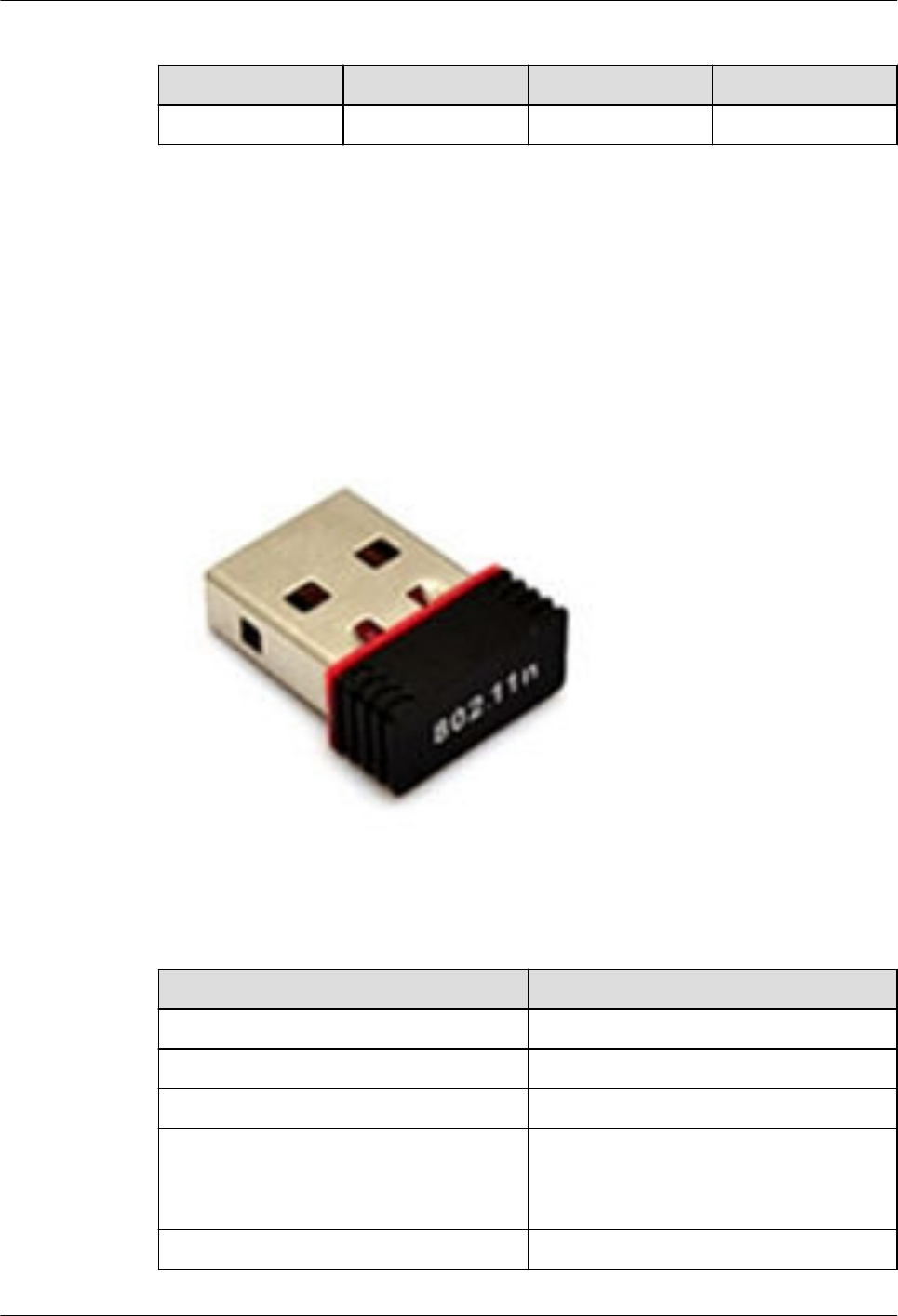
Table 6-2 Types of USB flash drives
No. Manufacturer Model Capacity
1 Netac U208 4 GB
6.3 Wi-Fi Module
A Wi-Fi module for an RTN 360 enables the Mobile LCT or Web LCT to connect to the RTN
360 using Wi-Fi, implementing contact-free configuration and maintenance.
Appearance
Figure 6-1 Wi-Fi module
Specifications
Table 6-3 Wi-Fi module specifications
Item Specifications
Port USB2.0 high-speed connector
Dimensions (H x W x D) 20 mm x 14 mm x 6 mm
Wireless mode Compatible with IEEE 802.11b/g/n
Maximum wireless rate lIEEE 802.11n: 150 Mbit/s
lIEEE 802.11g: 54 Mbit/s
lIEEE 802.11b: 11 Mbit/s
Frequency range 2.4 GHz to 2.4835 GHz
OptiX RTN 360 Radio Transmission System
Product Description 6 Accessories
Issue 01 (2016-01-15) Huawei Proprietary and Confidential
Copyright © Huawei Technologies Co., Ltd.
62

Item Specifications
Wireless transmit power Maximum power: 20 dBm
lIEEE 802.11b: 18±1 dBm
lIEEE 802.11g: 15±1 dBm
lIEEE 802.11n: 12±1 dBm
Receiver sensitivity l130 Mbit/s: -68 dBm@10% PER
l108 Mbit/s: -68 dBm@10% PER
l54 Mbit/s: -68 dBm@10% PER
l11 Mbit/s: -85 dBm@8% PER
l6 Mbit/s: -88 dBm@10% PER
l1 Mbit/s: -90 dBm@8% PER
Wi-Fi encryption mode WPA2-PSK
Setting of the service set identifier (SSID) Supported
Setting whether to enable Wi-Fi Supported
Setting of Wi-Fi passwords Supported
Frequency hopping (FH) Supported. The Wi-Fi module can
automatically select a good-quality channel
or be manually set to work at a fixed
channel.
Maximum transmission distance l30 m (laptop/mobile phone)
l70 m (laptop + external Wi-Fi network
adapter)
NOTE
30 m is obtained based on tests in which a laptop
(such as Lenovo Thinkpad X230) or mobile
phone (such as Huawei 8815) is used and there is
no obstacle between the laptop/mobile phone and
NE. The actual transmission distance may vary
according to performance of the laptop or mobile
phone used.
70 m is obtained based on tests in which a laptop
works with an external Wi-Fi network adapter
(such as Tenda W311U+) and there is no obstacle
between the laptop and NE. It is recommended
that an external Wi-Fi network adapter with 18
dBm transmit power, -86 dBm receiver
sensitivity, and an antenna of more than 4.2 dBi
gain be used or an external Wi-Fi network
adapter with better performance be used.
OptiX RTN 360 Radio Transmission System
Product Description 6 Accessories
Issue 01 (2016-01-15) Huawei Proprietary and Confidential
Copyright © Huawei Technologies Co., Ltd.
63

7 Cables
About This Chapter
This chapter describes the purpose, physical appearance, and connections of various cables
used with OptiX RTN 360s.
7.1 Outdoor Network Cables
Fitted with RJ45 connectors at both ends, outdoor network cables connect to Ethernet ports.
7.2 Outdoor Optical Fiber
Outdoor optical fibers are used for transmitting optical signals, and they fit outdoor scenarios.
7.3 RSSI Cables
Received signal strength indicator (RSSI) cables connect RSSI ports of RTN 360s to
multimeters.
7.4 RTN 360 PGND Cables
PGND cables are connected to ground screws and outdoor ground points (such as ground
points on towers) so that RTN 360 is connected to the outdoor ground grid.
OptiX RTN 360 Radio Transmission System
Product Description 7 Cables
Issue 01 (2016-01-15) Huawei Proprietary and Confidential
Copyright © Huawei Technologies Co., Ltd.
64
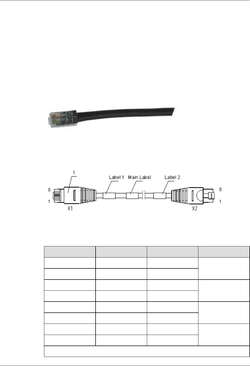
7.1 Outdoor Network Cables
Fitted with RJ45 connectors at both ends, outdoor network cables connect to Ethernet ports.
The GE electrical ports of PIs support the medium dependent interface (MDI), MDI crossover
(MDI-X), and auto-MDI/MDI-X modes. Straight-through cables and crossover cables can be
used to connect the NMS ports and GE electrical ports to MDIs or MDI-Xs. Straight-through
cables are recommended if network cables are made onsite.
Cable Diagram
Figure 7-1 Network cable
Pin Assignments
Table 7-1 Pin assignments for straight-through cables
Connector X1 Connector X2 Color Relationship
X1.1 X2.1 White/Orange Twisted pair
X1.2 X2.2 Orange
X1.3 X2.3 White/Green Twisted pair
X1.6 X2.6 Green
X1.4 X2.4 Blue Twisted pair
X1.5 X2.5 White/Blue
X1.7 X2.7 White/Brown Twisted pair
X1.8 X2.8 Brown
Braided shield
OptiX RTN 360 Radio Transmission System
Product Description 7 Cables
Issue 01 (2016-01-15) Huawei Proprietary and Confidential
Copyright © Huawei Technologies Co., Ltd.
65
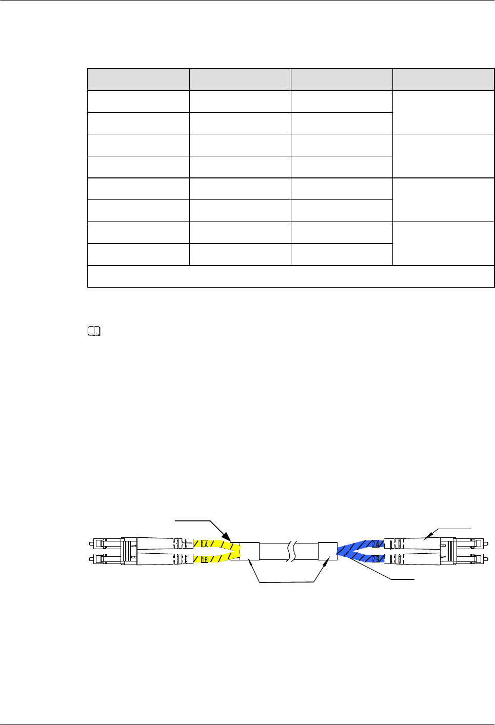
Table 7-2 Pin assignments for crossover cables
Connector X1 Connector X2 Color Relationship
X1.1 X2.3 White/Green Twisted pair
X1.2 X2.6 Green
X1.3 X2.1 White/Orange Twisted pair
X1.6 X2.2 Orange
X1.4 X2.4 Blue Twisted pair
X1.5 X2.5 White/Blue
X1.7 X2.7 White/Brown Twisted pair
X1.8 X2.8 Brown
Braided shield
NOTE
lStraight-through cables are used between MDIs and MDI-Xs, and crossover cables are used between
MDIs or between MDI-Xs. The only difference between straight-through cables and crossover
cables is with regard to their pin assignments.
7.2 Outdoor Optical Fiber
Outdoor optical fibers are used for transmitting optical signals, and they fit outdoor scenarios.
Fiber Diagram
Figure 7-2 Optical fiber (Single-mode)
DLC/UPC DLC/UPC
Identifier
Yellow
Junction implement
(With glue)(Black)
Blue
OptiX RTN 360 Radio Transmission System
Product Description 7 Cables
Issue 01 (2016-01-15) Huawei Proprietary and Confidential
Copyright © Huawei Technologies Co., Ltd.
66
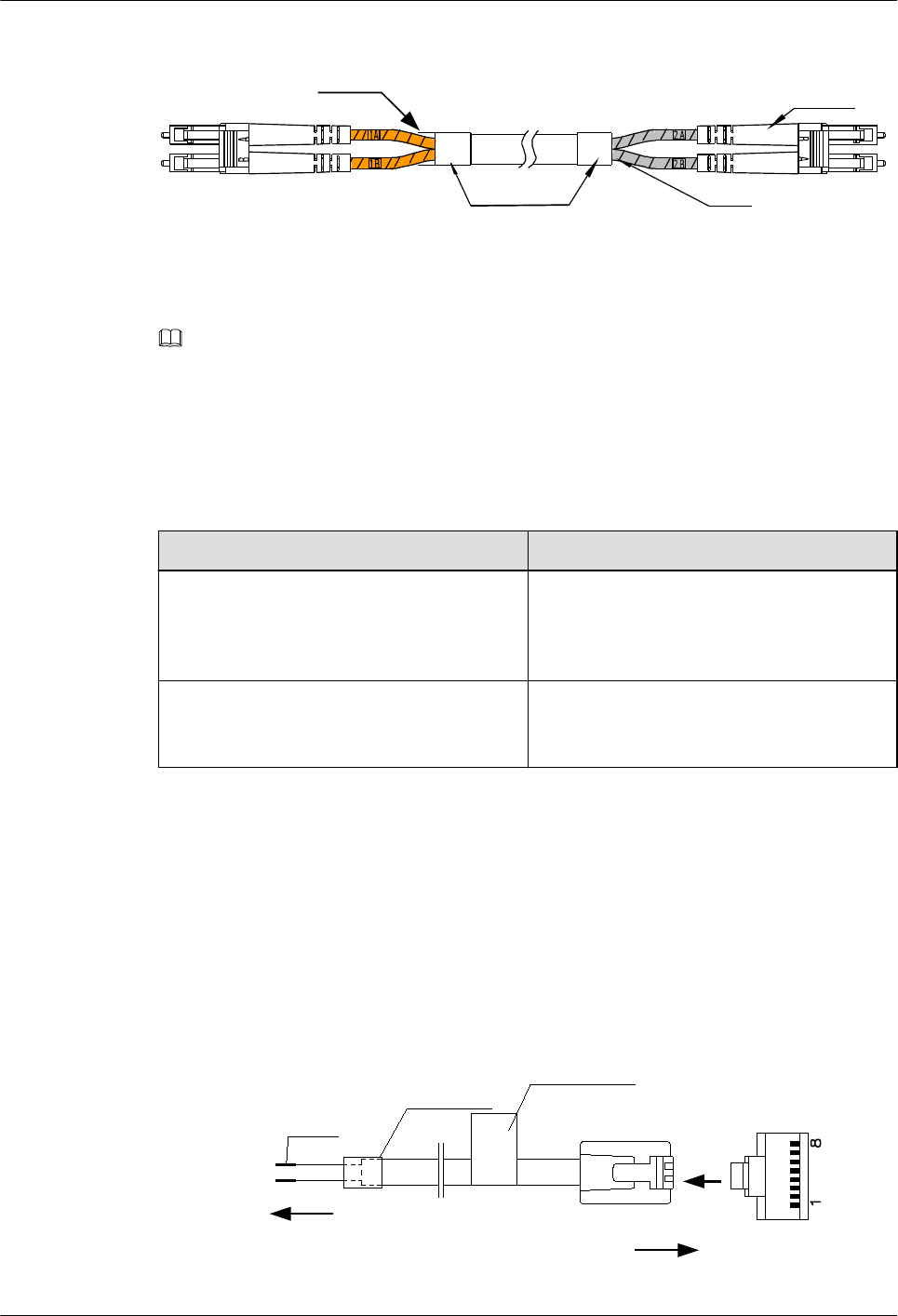
Figure 7-3 Optical fiber (Multi-mode)
DLC/PC DLC/PC
Identifier
Orange
Junction implement
(With glue)(Black)
Gray
NOTE
lFiber connectors must be fit into outdoor protective tubes.
lOptical fibers already have correct receive/transmit connections at both ends.
Technical Specifications
Table 7-3 Technical specifications of optical fibers
Connector Type Fiber Parameter
DLC/UPC Single-mode, GYFJH 2B1.3 (low smoke
and zero halogen), 7.0 mm, 2-core, 0.03 m/
0.34 m, 2 mm, outdoor protected branch
cable
DLC/PC Multi-mode, GYFJH 2A1a (low smoke zero
halogen), 7.0 mm, 2-core, 0.03 m/0.34 m, 2
mm, outdoor protected branch cable
7.3 RSSI Cables
Received signal strength indicator (RSSI) cables connect RSSI ports of RTN 360s to
multimeters.
Cable Diagram
Figure 7-4 RSSI cable
Connected to
a multimeter
testing RSSI Connected to the RSSI
port
Tin
H.S. tube
Main label
View A
WA
OptiX RTN 360 Radio Transmission System
Product Description 7 Cables
Issue 01 (2016-01-15) Huawei Proprietary and Confidential
Copyright © Huawei Technologies Co., Ltd.
67

Pin Assignments
An RSSI cable uses two cores to detect level signals.
Table 7-4 Pin assignments for RSSI cables
Pin Signal
4 Ground signal
7 RSSI test level signal
7.4 RTN 360 PGND Cables
PGND cables are connected to ground screws and outdoor ground points (such as ground
points on towers) so that RTN 360 is connected to the outdoor ground grid.
Cable Diagram
Figure 7-5 RTN 360 PGND cable
1
1. Bare crimp terminal, OT
OptiX RTN 360 Radio Transmission System
Product Description 7 Cables
Issue 01 (2016-01-15) Huawei Proprietary and Confidential
Copyright © Huawei Technologies Co., Ltd.
68

A Appendix
A.1 Port Loopbacks
The loopback capabilities of ports on RTN 360 differ based on the port type.
A.2 Component Photos
This section provides photos of major components of an RTN 360.
A.3 Compliance Standards
OptiX RTN 360 Radio Transmission System
Product Description A Appendix
Issue 01 (2016-01-15) Huawei Proprietary and Confidential
Copyright © Huawei Technologies Co., Ltd.
69

A.1 Port Loopbacks
The loopback capabilities of ports on RTN 360 differ based on the port type.
Table A-1 Port loopbacks
Port Type Loopback Capability
Microwave port lInloops at the IF port
lInloops at the composite port
GE port lInloops at the MAC layer
lInloops at the PHY layer
A.2 Component Photos
This section provides photos of major components of an RTN 360.
RTN 360
Figure A-1 Front view
OptiX RTN 360 Radio Transmission System
Product Description A Appendix
Issue 01 (2016-01-15) Huawei Proprietary and Confidential
Copyright © Huawei Technologies Co., Ltd.
70
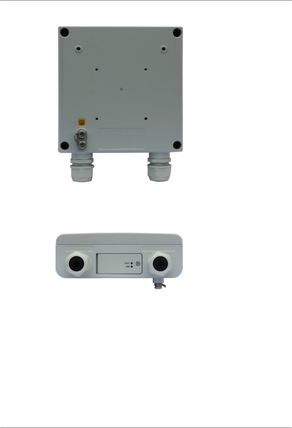
Figure A-2 Rear view
Figure A-3 Ports
A.3 Compliance Standards
A.3.1 ITU-R Standards
OptiX RTN 360 complies with the ITU-R standards designed for radio equipment.
OptiX RTN 360 Radio Transmission System
Product Description A Appendix
Issue 01 (2016-01-15) Huawei Proprietary and Confidential
Copyright © Huawei Technologies Co., Ltd.
71

Table A-2 ITU-R standard
Standard Description
ITU-R F.1093 Effects of multipath propagation on the design and operation of
line-of-sight digital fixed wireless systems
ITU-R F.1094 Maximum allowable error performance and availability
degradations to digital fixed wireless systems arising from radio
interference from emissions and radiations from other sources
ITU-R F.1102 Characteristics of fixed wireless systems operating in frequency
bands above about 17 GHz
ITU-R F.1191 Bandwidths and unwanted emissions of digital fixed service
systems
ITU-R F.1565 Performance degradation due to interference from other services
sharing the same frequency bands on a co-primary basis with real
digital fixed wireless systems used in the international and national
portions of a 27 500 km hypothetical reference path at or above the
primary rate
ITU-R F.1605 Error performance and availability estimation for synchronous
digital hierarchy terrestrial fixed wireless systems
ITU-R F.1668 Error performance objectives for real digital fixed wireless links
used in 27 500 km hypothetical reference paths and connections
ITU-R F.1703 Availability objectives for real digital fixed wireless links used in
27 500 km hypothetical reference paths and connections
ITU-R F.592 Vocabulary of terms for the fixed service
ITU-R F.746 Radio-frequency arrangements for fixed service systems
ITU-R F.752 Diversity techniques for point-to-point fixed wireless systems
ITU-R F.758 Considerations in the development of criteria for sharing between
the terrestrial fixed service and other services
ITU-R SM.329 Unwanted emissions in the spurious domain
ITU-R P.525 Calculation of free-space attenuation
ITU-R P.530 Propagation data and prediction methods required for the design of
terrestrial line-of-sight systems
ITU-R P.676 Attenuation by atmospheric gases
ITU-R P.837 Characteristics of precipitation for propagation modelling
ITU-R P.838 Specific attenuation model for rain for use in prediction methods
ITU-R P.836 Information on water vapour density
ITU-R F.2107 characteristics and applications of fixed wireless systems operating
in frequency ranges between 57 GHz and 134 GHz
OptiX RTN 360 Radio Transmission System
Product Description A Appendix
Issue 01 (2016-01-15) Huawei Proprietary and Confidential
Copyright © Huawei Technologies Co., Ltd.
72

Standard Description
ITU-R SM.328 Spectra and bandwidth of emissions
ITU-R SM.1045 Frequency tolerance of transmitters
ITU-R SM.1539-1 Variation of the boundary between the out-of-band and spurious
domains required for the application of Recommendations ITU-R
SM.1541 and ITU-R SM.329
ITU-R SM.1541 Unwanted emissions in the out-of-band domain
ITU-R F.1519 Guidance on frequency arrangements based on frequency blocks for
systems in the fixed service
A.3.2 ITU-T Standards
OptiX RTN 360 complies with the ITU-T standards.
Table A-3 ITU-T standard
Standard Description
ITU-T G.8011 Ethernet over Transport - Ethernet services
framework
ITU-T G.8011.1 Ethernet private line service
ITU-T G.8011.2 Ethernet virtual private line service
ITU-T G.8261 Timing and synchronization aspects in
packet networks
ITU-T G.8262 Timing characteristics of synchronous
ethernet equipment slave clock (EEC)
ITU-T G.8264 Timing distribution through packet
networks
ITU-T G.8032 Ethernet ring protection switching
ITU-T G.8012 Ethernet UNI and Ethernet over transport
NNI
ITU-T Y.1730 Requirements for OAM functions in
Ethernet based networks and Ethernet
services
ITU-T Y.1731 OAM functions and mechanisms for
Ethernet based networks
ITU-T G.8031 Ethernet protection switching
ITU-T G.8010 Architecture of Ethernet layer networks
OptiX RTN 360 Radio Transmission System
Product Description A Appendix
Issue 01 (2016-01-15) Huawei Proprietary and Confidential
Copyright © Huawei Technologies Co., Ltd.
73

Standard Description
ITU-T G.8021 Characteristics of Ethernet transport
network equipment functional blocks
ITU-T Y.1291 An architectural framework for support of
quality of service (QoS) in packet networks
ITU-T K.20 Resistibility of telecommunication
equipment installed in a
telecommunications centre to overvoltages
and overcurrents
ITU-T K.21 Resistibility of telecommunication
equipment installed in customer premises to
overvoltages and overcurrents
ITU-T K.27 Bonding configurations and earthing inside
a telecommunication building
ITU-T K.41 Resistibility of internal interfaces of
telecommunication centres to surge
overvoltages
ITU-T K.45 Resistibility of telecommunication
equipment installed in the access and trunk
networks to overvoltages and overcurrents
A.3.3 ETSI Standards
OptiX RTN 360 complies with the ETSI standards designed for radio equipment.
Table A-4 ETSI standard
Standard Description
ETSI EN 301 489-1 Electromagnetic compatibility and Radio spectrum Matters(ERM);
Electromagnetic Compatibility(EMC) standard for radio equipment
and services; Part 1: Common technical requirements
ETSI EN 301 489-4 Electromagnetic compatibility and Radio spectrum Matters(ERM);
Electromagnetic Compatibility(EMC) standard for radio equipment
and services; Part 4: Specific conditions for fixed radio links and
ancillary equipment and services
ETSI EN 301 390 Fixed Radio Systems; Point-to-point and Multipoint Systems;
Spurious emissions and receiver immunity limits at equipment/
antenna port of Digital Fixed Radio Systems
ETSI TR 102 457 Transmission and Multiplexing (TM);Study on the electromagnetic
radiated field in fixed radio systems for environmental issuesStudy
on the electromagnetic radiated field in fixed radio systems for
environmental issues
OptiX RTN 360 Radio Transmission System
Product Description A Appendix
Issue 01 (2016-01-15) Huawei Proprietary and Confidential
Copyright © Huawei Technologies Co., Ltd.
74

Standard Description
ETSI EN 300 132-2 Environmental Engineering (EE); Power supply interface at the
input to telecommunications equipment; Part 2: Operated by direct
current (dc)
ETSI EN 300
019-1-1 (Class 1.2)
Environmental conditions and environmental tests for
telecommunications equipment; Part 1-1: Classification of
environmental conditions;Storage Class 1.2
ETSI EN 300
019-1-2 (Class 2.3)
Environmental conditions and environmental tests for
telecommunications equipment; Part 1-2: Classification of
environmental conditions; Transportation Class 2.3
ETSI EN 300
019-1-3 (Indoor
Unit Class 3.2)
Environmental Engineering (EE); Environmental conditions and
environmental tests for telecommunications equipment; Part 1-3:
Classification of environmental conditions; Stationary use at
weatherprotected locations
ETSI EN 300
019-1-4 (Outdoor
Unit Class 4.1)
Environmental Engineering (EE); Environmental conditions and
environmental tests for telecommunications equipment; Part 1-4:
Classification of environmental conditions; Stationary use at non-
weather protected locations
ETSI EN 300
019-2-1
Environmental Engineering (EE); Environmental conditions and
environmental tests for telecommunications equipment; Part 2-1:
Specification of environmental tests; Storage
ETSI EN 300
019-2-2
Environmental Engineering (EE); Environmental conditions and
environmental tests for telecommunications equipment; Part 2-2:
Specification of environmental tests; Transportation
ETSI EN 300
019-2-4
Environmental Engineering (EE); Environmental conditions and
environmental tests for telecommunications equipment; Part 2-4:
Specification of environmental tests; Stationary use at non-
weatherprotected locations
ETSI TR 102 489 Thermal Management Guidance for equipment and its deployment
ETSI EN 301 126-1 Fixed Radio Systems; Conformance testing;Part 1: Point-to-point
equipment - Definitions, general requirements and test procedures
ETSI EN 301
126-3-1
Fixed Radio Systems; Conformance testing;Part 3-1: Point-to-Point
antennas; Definitions, general requirements and test procedures
ETSI EN 302 217-1 Fixed Radio Systems; Characteristics and requirements for point-to-
point equipment and antennas; Part 1: Overview and system-
independent common characteristics
ETSI EN 302
217-2-1
Fixed Radio Systems; Characteristics and requirements for point-to-
point equipment and antennas; Part 2-1: System-dependent
requirements for digital systems operating in frequency bands
where frequency co-ordination is applied
OptiX RTN 360 Radio Transmission System
Product Description A Appendix
Issue 01 (2016-01-15) Huawei Proprietary and Confidential
Copyright © Huawei Technologies Co., Ltd.
75

Standard Description
ETSI EN 302 217-3 Fixed Radio Systems; Characteristics and requirements for point-to-
point equipment and antennas; Part 3: Equipment operating in
frequency bands where both frequency coordinated or
uncoordinated deployment might be applied; Harmonized EN
covering the essential requirements of article 3.2 of the R&TTE
Directive
ETSI EN 302
217-4-1
Fixed Radio Systems; Characteristics and requirements for point-to-
point equipment and antennas; Part 4-1: System-dependent
requirements for antennas
ETSI EN 302
217-4-2
Fixed Radio Systems; Characteristics and requirements for point-to-
point equipment and antennas; Part 4-2: Antennas; Harmonized EN
covering the essential requirements of article 3.2 of the R&TTE
Directive
ETSI TR 102 565 Fixed Radio Systems (FRS); Point-to-point systems; Requirements
and bit rates of PtP Fixed Radio Systems with packet data
interfaces, effects of flexible system parameters, use of mixed
interfaces and implications on IP/ATM networksReq.s and bit rates
of systems wit packet data interfaces applying RIC-rates not
covered by PDH/SDH.
ETSI EN 300 253 Environmental Engineering (EE); Earthing and bonding of
telecommunication equipment in telecommunication centres
ETSI EN 300 119 Environmental Engineering (EE); European telecommunication
standard for equipment practice;
ETSI ES 201 468
Ver. 1.3.1
Electromagnetic compatibility and Radio spectrum Matters (ERM);
Additional ElectroMagnetic Compatibility (EMC) requirements and
resistibility requirements for telecommunications equipment for
enhanced availability of service in specific applications
ETSI TR 103 820 Fixed Radio Systems;Energy efficiency metrics and test procedures
for Point-to-point fixed radio systems
ETSI TR 103 053 Access, Terminals, Transmission and Multiplexing (ATTM)Fixed
Radio Systems;Parameters affecting the Signal-to-Noise Ratio
(SNR) and the Receiver Signal Level (RSL) threshold in point-to-
point receivers; Theory and practice
ETSI TR 102 243-1 Fixed Radio Systems; Representative values for transmitter power
and antenna gain to support inter- and intra-compatibility and
sharing analysis; Part 1: Digital point-to-point systems
A.3.4 CEPT Standards
OptiX RTN 360 complies with the CEPT standards.
OptiX RTN 360 Radio Transmission System
Product Description A Appendix
Issue 01 (2016-01-15) Huawei Proprietary and Confidential
Copyright © Huawei Technologies Co., Ltd.
76

Table A-5 CEPT Standards
Standard Description
ERC/REC 74-01 Unwanted Emissions in the Spurious Domain
ECC/REC/(02)05 Use of the 64-66 GHz frequency band for Fixed Service
A.3.5 IEC Standards
OptiX RTN 360 complies with the IEC standards related to the waveguide.
Table A-6 IEC standards
Standard Description
IEC 60154-1 Flanges for waveguides. Part 1: General requirements
IEC 60154-2 Flanges for waveguides. Part 2: Relevant specifications for
flanges for ordinary rectangular waveguides
IEC 60154-3 Flanges for waveguides. Part 3: Relevant specifications for
flanges for flat rectangular waveguides
IEC 60154-4 Flanges for waveguides. Part 4: Relevant specifications for
flanges for circular waveguides
IEC 60154-6 Flanges for waveguides. Part 6: Relevant specifications for
flanges for medium flat rectangular waveguides
IEC 60154-7 Flanges for waveguides-Part 7: Relevant specifications for
flanges for square waveguides
IEC 60153-1 Hollow metallic waveguides. Part 1 : General requirements and
measuring methods
IEC 60153-2 Hollow metallic waveguides. Part 2 : Relevant specifications for
ordinary rectangular waveguides
IEC 60153-3 Hollow metallic waveguides. Part 3 : Relevant specifications for
flat rectangular waveguides
IEC 60153-4 Hollow metallic waveguides. Part 4 : Relevant specifications for
circular waveguides
IEC 60153-6 Hollow metallic waveguides. Part 6 : Relevant specifications for
medium flat rectangular waveguides
IEC 60153-7 Hollow metallic waveguides. Part 7 : Relevant specifications for
square waveguides
IEC 60215 Safety requirements for radio transmitting equipment
IEC 60529 Degrees of protection provided by enclosures
IEC 60825 Safety of laser products
OptiX RTN 360 Radio Transmission System
Product Description A Appendix
Issue 01 (2016-01-15) Huawei Proprietary and Confidential
Copyright © Huawei Technologies Co., Ltd.
77

Standard Description
IEC 60950-1 Information technology equipment — Safety — Part 1 General
requirements
IEC 60950-22 Information technology equipment — Safety — Part 22
Equipment installed outdoors
IEC 60657 Non-ionizing radiation hazards in the frequency range from 10
MHz to 300 000 MHz
IEC 60297 Dimensions of mechanical structures of the 482.6 mm (19 in)
series
IEC 60529 Degrees of protection provided by enclosures
IEC 721-3-4 Classes
4K2/4Z5/4Z7/4B1/4C
2(4C3)/4S2/4M5
(Outdoor Unit)
Classification of environmental conditions - Part 3: Classification
of groups of environmental parameters and their severities -
Section 4: Stationary use at non-weather protected locations.
Classes 4K2/4Z5/4Z7/4B1/4C2(4C3)/4S2/4M5
IEC 61000-4-2 Electromagnetic compatibility(EMC) Part 2:Testing and
measurement techniques Section 2:Electrostatic discharge
immunity test Basic EMC Publication
IEC 61000-4-3 Electromagnetic compatibility; Part 3:Testing and measurement
techniques Section 3 radio frequency electromagnetic fields;
immunity test.
IEC 61000-4-4 Electromagnetic compatibility(EMC) Part 4:Testing and
measurement techniques Section 4:Electrical fast transient/burst
immunity test Basic EMC publication
IEC 61000-4-5 Electromagnetic compatibility(EMC) Part 5:Testing and
measurement techniques Section 5:Sruge immunity test
IEC 61000-4-6 Electromagnetic compatibility:Part 6:Testing and measurement
techniques:Section 6 conducted disturbances induced by radio-
frequency fields;immunity test
IEC 61000-4-29 Electromagnetic compatibility:Part 29:Testing and measurement
techniques -Voltage dips,short interruptinns and voltage variations
on DC input power port immunity tests
A.3.6 IETF Standards
OptiX RTN 360 complies with IETF standards.
Table A-7 IETF standards
Standard Description
RFC 791 Internet Protocol
OptiX RTN 360 Radio Transmission System
Product Description A Appendix
Issue 01 (2016-01-15) Huawei Proprietary and Confidential
Copyright © Huawei Technologies Co., Ltd.
78

Standard Description
RFC 2819 Remote Network Monitoring Management Information
Base
RFC 1661 The Point-to-Point Protocol(PPP)
RFC 1662 PPP in HDLC-like Framing
RFC 2615 PPP over SONET/SDH
draft-ietf-l2vpn-oam-req-
frmk-05
L2VPN OAM requirements and framework
draft-ietf-l2vpn-signaling-08 Provisioning, autodiscovery, and signaling in L2VPNs
RFC 4664 Framework for layer 2 virtual private networks
(L2VPNs)
RFC 3289 Management information base for the differentiated
services architecture
RFC 3644 Policy quality of service (QoS) Information model
RFC 3670 Information model for describing network device QoS
datapath mechanisms
RFC 2212 Specification of guaranteed quality of service
RFC 2474 Definition of the Differentiated Services Field(DS Field)
in the IPv4 and IPv6 Headers
RFC 2475 An architecture for differentiated services
RFC 2597 Assured forwarding PHB group
RFC 3140 Per hop behavior identification codes
RFC 3246 An expedited forwarding PHB (Per-hop behavior)
STD 0062 An Architecture for Describing Simple Network
Management Protocol (SNMP) Management
Frameworks
A.3.7 IEEE Standards
OptiX RTN 360 complies with the IEEE standards designed for Ethernet networks.
Table A-8 IEEE standards
Standard Description
IEEE 802.1D Media Access Control (MAC) Bridges
IEEE 802.3 Carrier Sense Multiple Access with Collision Detection (CSMA/CD)
access method and physical layer specifications
OptiX RTN 360 Radio Transmission System
Product Description A Appendix
Issue 01 (2016-01-15) Huawei Proprietary and Confidential
Copyright © Huawei Technologies Co., Ltd.
79

Standard Description
IEEE 802.1Q Virtual Bridged Local Area Networks
IEEE 802.1ag Virtual Bridged Local Area Networks — Amendment 5: Connectivity
Fault Management
IEEE 802.3ah Media Access Control Parameters, Physical Layers, and Management
Parameters for Subscriber Access Networks
IEEE 802.3x Supplements to Carrier Sense Multiple Access With Collision Detection
(CSMA/CD) Access Method and Physical Layer Specifications
A.3.8 Other Standards
This section describes other standards with which OptiX RTN 360 complies.
Table A-9 Other standards
Standard Description
EN 50289 Communication cables - Specifications for test methods
EN 50392 Generic standard to demonstrate the compliance of electronic and
electrical apparatus with the basic restrictions related to human
exposure to electromagnetic fields (0 Hz - 300 GHz)
EN 62311 Assessment of electronic and electrical equipment related to human
exposure restrictions for electromagnetic fields (0 Hz – 300 GHz)
EN 50383 Basic standard for the calculation and measurement of
electromagnetic field strength and SAR related to human exposure
from radio base stations and fixed terminal stations for wireless
telecommunications system (110 MHz - 40 GHz)
EN 50385 Product standard to demonstrate the compliances of radio base
stations and fixed terminal stations for wireless telecommunication
systems with the basic restrictions or the reference levels related to
human exposure to ratio frequency electromagnetic
fields(110MHz-40GHz)-General public
EN 55022 Information technology equipment - Radio disturbance
characteristics - Limits and methods of measurement (IEC/CISPR
22:1997, modified + A1:2000); German version EN 55022:1998 +
Corrigendum:2001 + A1:2000
EN 55024 Information technology equipment - Immunity characteristics -
Limits and methods of measurement
EN 41003 Particular safety requirements for equipment to be connected to
telecommunication networks;
EN 60215 safty requirements for radio transmitting equipment
OptiX RTN 360 Radio Transmission System
Product Description A Appendix
Issue 01 (2016-01-15) Huawei Proprietary and Confidential
Copyright © Huawei Technologies Co., Ltd.
80

Standard Description
EN 60950-1 Information technology equipment — Safety — Part 1 General
requirements
EN 60950-22 Information technology equipment — Safety — Part 22 Equipment
installed outdoors
EN 60529 Degrees of protection provided by enclosures (IP code) (IEC
60529:1989 + A1:1999); German version EN 60529:1991 +
A1:2000
EN 61000-3-2 Electromagnetic compatibility (EMC) — Part 3-2: Limits — Limits
for harmonic current emissions (equipment input current< 16 A per
phase)
EN 61000-3-3 Electromagnetic compatibility(EMC) ––Part 3-3: Limits —
Limitation of voltage changes, voltage fluctuations and flicker in
public low-voltage supply systems, for equipment with rated current
< – 16 A per phase and not subject toconditional connection
EN 61000-4-2 CENELEC. EMC Part 4: Testing and measurement techniques -
Section 2: Electrostatic discharge immunity test
EN 61000-4-3 CENELEC. EMC Part 4: Testing and measurement techniques -
Section 3: Radiated, radio-frequency, electromagnetic field
immunity test.
EN 61000-4-4 CENELEC. EMC Part 4: Testing and measurement techniques -
Section 4: Electrical fast transient/burst immunity test.
EN 61000-4-5 CENELEC. EMC Part 4: Testing and measurement techniques -
Section 5: Surge Immunity test.
EN 61000-4-6 CENELEC. EMC Part 4: Testing and measurement techniques -
Section 6: Immunity to conducted disturbances induced by radio
frequency field.
AF-PHY-0086.001 AF-PHY-0086.001 Inverse Multiplexing for ATM Specification
Version 1.1
AF-TM-0121.000 Traffic Management Specification
MEF2 Requirements and Framework for Ethernet Service Protection in
Metro Ethernet Networks
MEF4 Metro Ethernet network architecture framework - Part 1: generic
framework
MEF10 Ethernet services attributes phase 1
MEF9 Abstract Test Suite for Ethernet Services at the UNI
MEF14 Abstract Test Suite for Traffic Management Phase 1
CISPR 22(2010) limits and methods of measurement of radio disturbance
characteristics of information
OptiX RTN 360 Radio Transmission System
Product Description A Appendix
Issue 01 (2016-01-15) Huawei Proprietary and Confidential
Copyright © Huawei Technologies Co., Ltd.
81

Standard Description
CISPR 24(2010) Information Technology Equipment -Immunity characteristics -
Limits and methods measurement
OptiX RTN 360 Radio Transmission System
Product Description A Appendix
Issue 01 (2016-01-15) Huawei Proprietary and Confidential
Copyright © Huawei Technologies Co., Ltd.
82