Huawei Technologies RU3832 Remote Radio Unit User Manual Hardware Description
Huawei Technologies Co.,Ltd Remote Radio Unit Hardware Description
UserManual.wiki
>
Huawei Technologies
>
RU3832 User Manual
>
User manual I
Contents
1.
User manual I
2.
User manual II
3.
User manual III
4.
User manual IV
User manual I
Navigation menu
Upload a User Manual
Namespaces
Wiki Guide
HTML
PDF
Info
Views
User Manual
Discussion / Help
Navigation
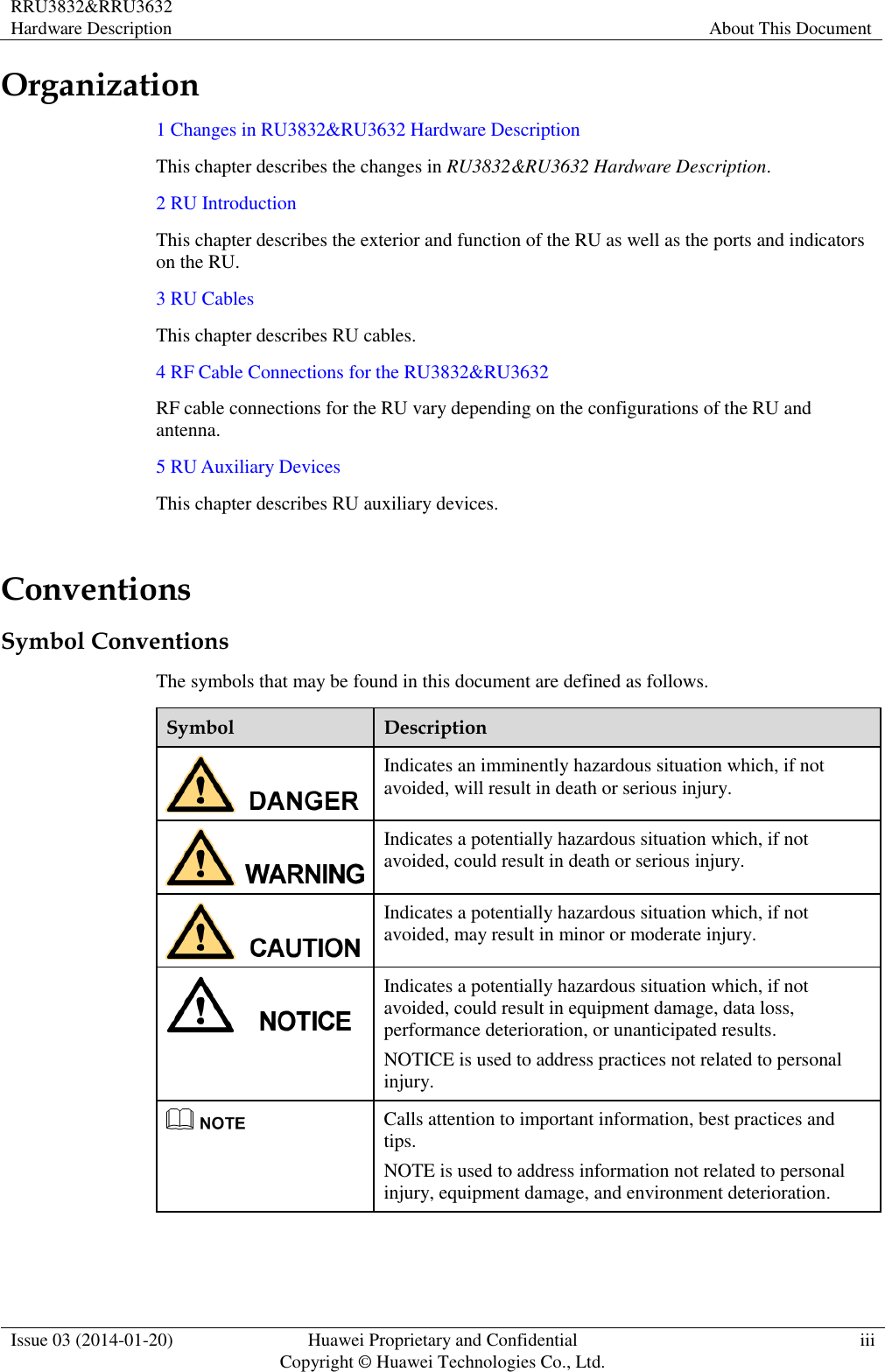
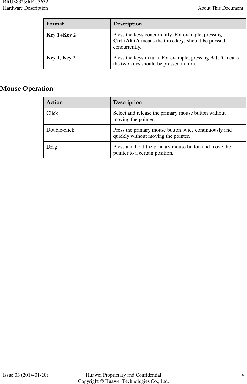
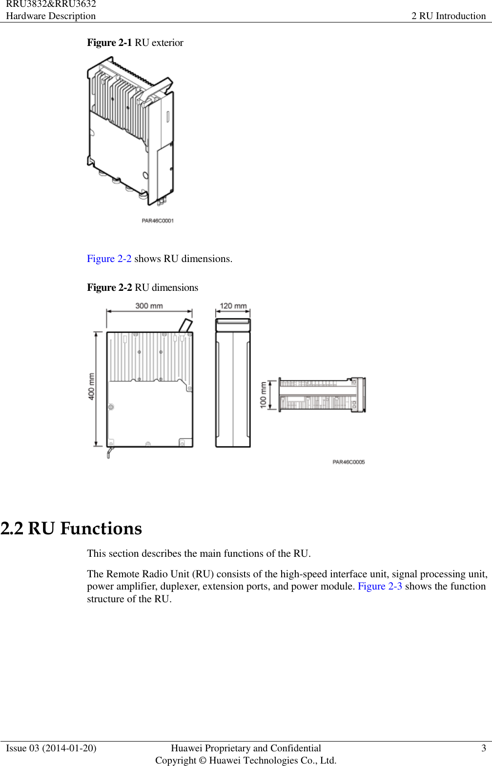
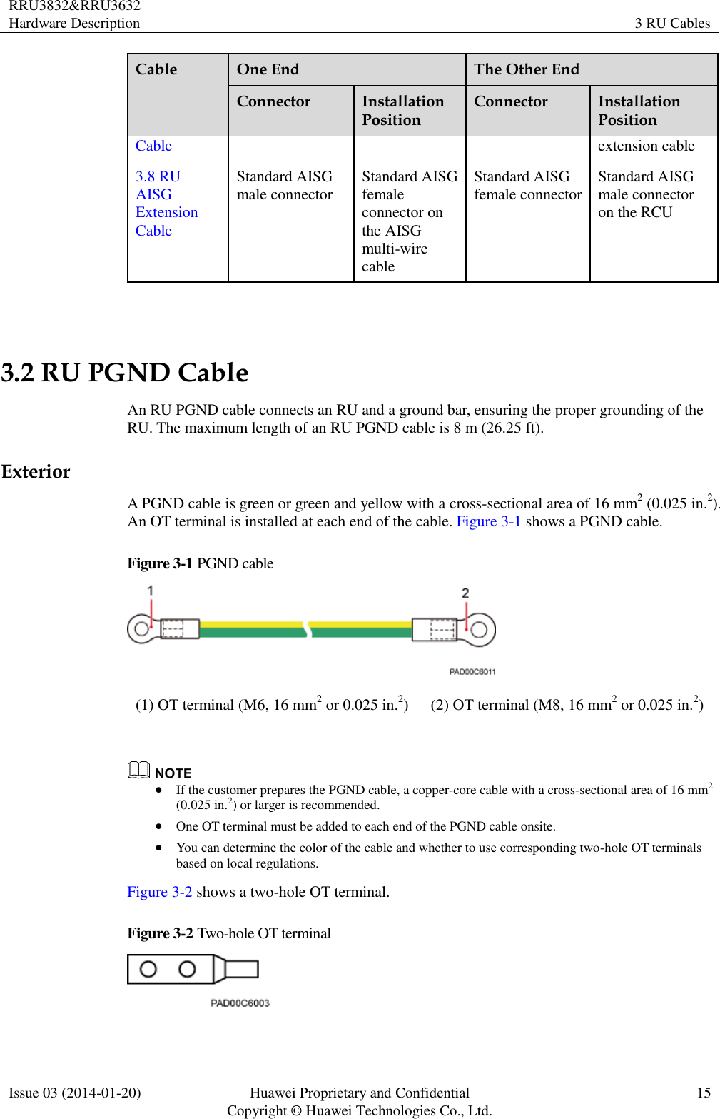
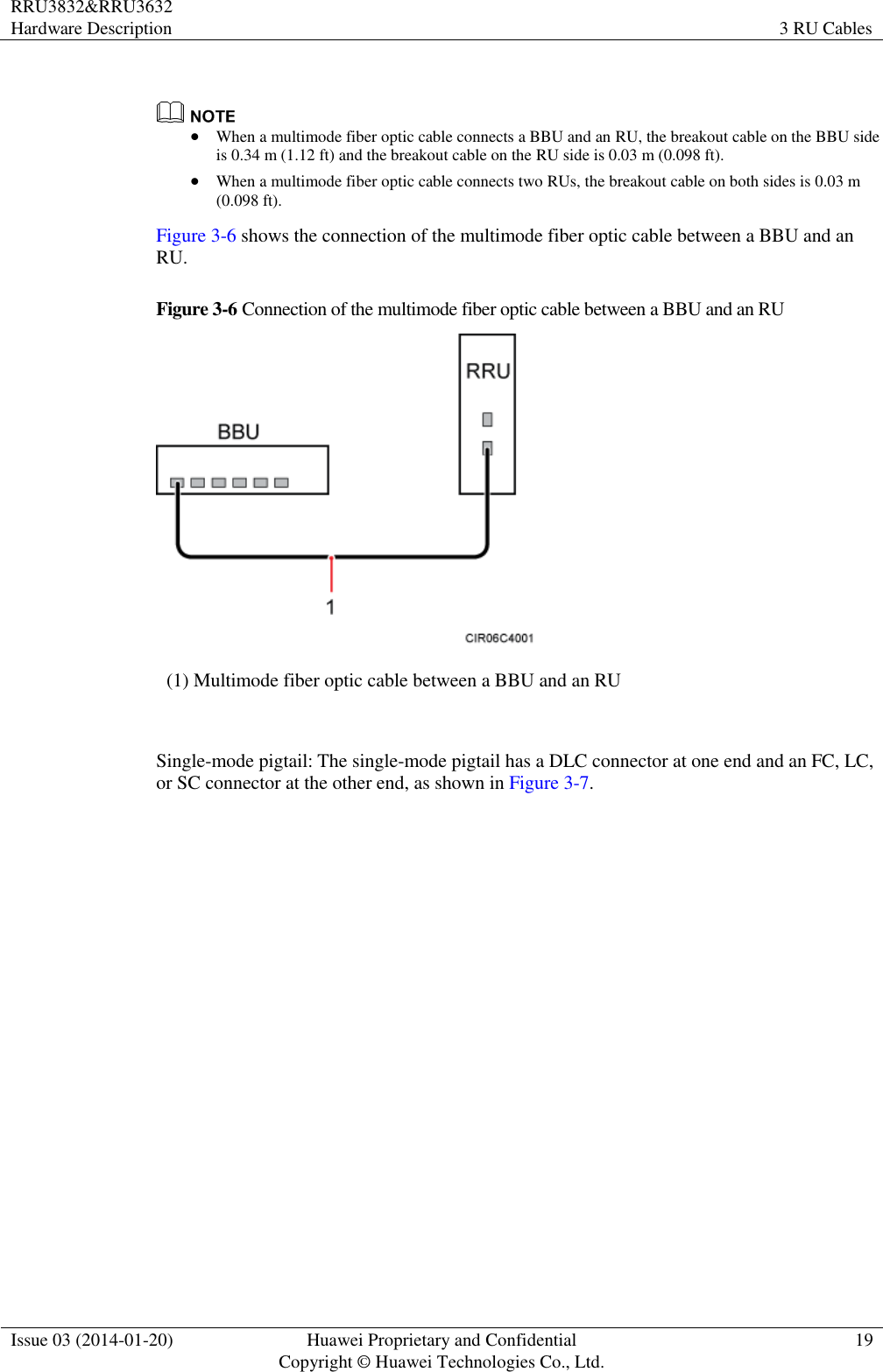
![RRU3832&RRU3632 Hardware Description About This Document Issue 03 (2014-01-20) Huawei Proprietary and Confidential Copyright © Huawei Technologies Co., Ltd. iv General Conventions Convention Description Times New Roman Normal paragraphs are in Times New Roman. Boldface Names of files, directories, folders, and users are in boldface. For example, log in as user root. Italic Book titles are in italics. Courier New Terminal display is in Courier New. Command Conventions Convention Description Boldface The keywords of a command line are in boldface. Italic Command arguments are in italics. [ ] Items (keywords or arguments) in square brackets [ ] are optional. { x | y | ... } Alternative items are grouped in braces and separated by vertical bars. One is selected. [ x | y | ... ] Optional alternative items are grouped in square brackets and separated by vertical bars. One or none is selected. { x | y | ... } * Alternative items are grouped in braces and separated by vertical bars. A minimum of one or a maximum of all can be selected. GUI Conventions Convention Description Boldface Buttons, menus, parameters, tabs, windows, and dialog titles are in boldface. For example, click OK. > Multi-level menus are in boldface and separated by the ">" signs. For example, choose File > Create > Folder. Keyboard Operation Format Description Key Press the key. For example, press Enter and press Tab.](https://usermanual.wiki/Huawei-Technologies/RU3832.User-manual-I/User-Guide-2407259-Page-5.png)