Huawei Technologies RU3832 Remote Radio Unit User Manual Installation Guide
Huawei Technologies Co.,Ltd Remote Radio Unit Installation Guide
UserManual.wiki
>
Huawei Technologies
>
RU3832 User Manual
>
User manual II
Contents
1.
User manual I
2.
User manual II
3.
User manual III
4.
User manual IV
User manual II
Navigation menu
Upload a User Manual
Namespaces
Wiki Guide
HTML
PDF
Info
Views
User Manual
Discussion / Help
Navigation
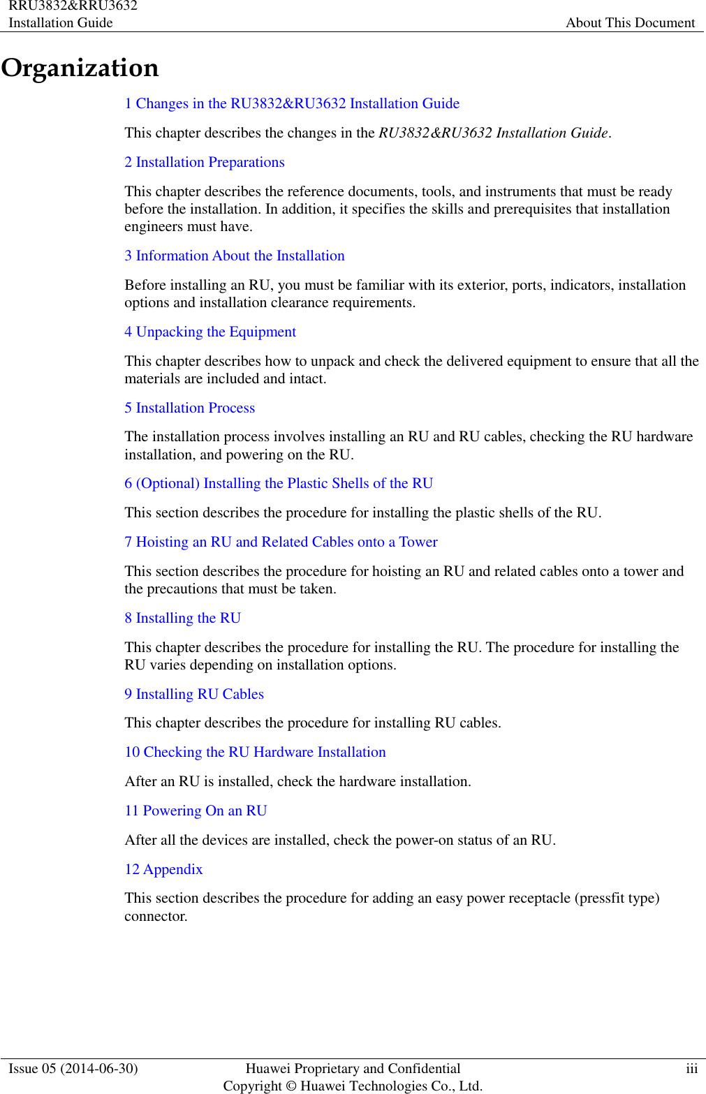
![RRU3832&RRU3632 Installation Guide About This Document Issue 05 (2014-06-30) Huawei Proprietary and Confidential Copyright © Huawei Technologies Co., Ltd. v Convention Description [ ] Items (keywords or arguments) in square brackets [ ] are optional. { x | y | ... } Alternative items are grouped in braces and separated by vertical bars. One is selected. [ x | y | ... ] Optional alternative items are grouped in square brackets and separated by vertical bars. One or none is selected. { x | y | ... } * Alternative items are grouped in braces and separated by vertical bars. A minimum of one or a maximum of all can be selected. GUI Conventions Convention Description Boldface Buttons, menus, parameters, tabs, windows, and dialog titles are in boldface. For example, click OK. > Multi-level menus are in boldface and separated by the ">" signs. For example, choose File > Create > Folder. Keyboard Operation Format Description Key Press the key. For example, press Enter and press Tab. Key 1+Key 2 Press the keys concurrently. For example, pressing Ctrl+Alt+A means the three keys should be pressed concurrently. Key 1, Key 2 Press the keys in turn. For example, pressing Alt, A means the two keys should be pressed in turn. Mouse Operation Action Description Click Select and release the primary mouse button without moving the pointer. Double-click Press the primary mouse button twice continuously and quickly without moving the pointer. Drag Press and hold the primary mouse button and move the pointer to a certain position.](https://usermanual.wiki/Huawei-Technologies/RU3832.User-manual-II/User-Guide-2407260-Page-6.png)
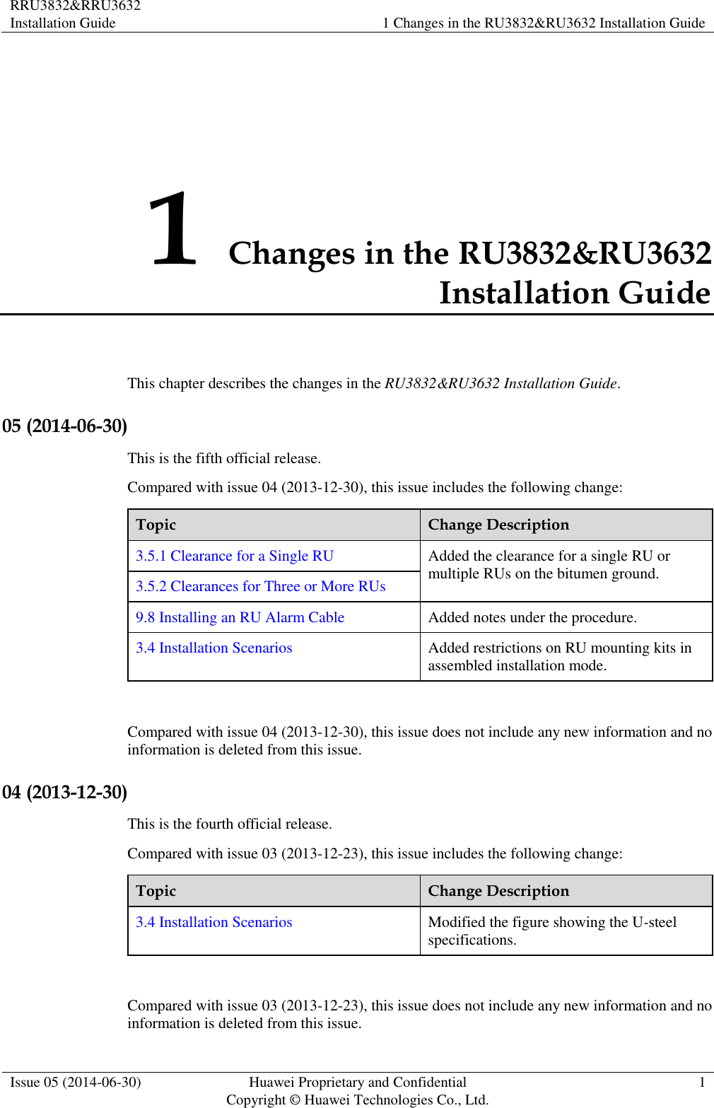
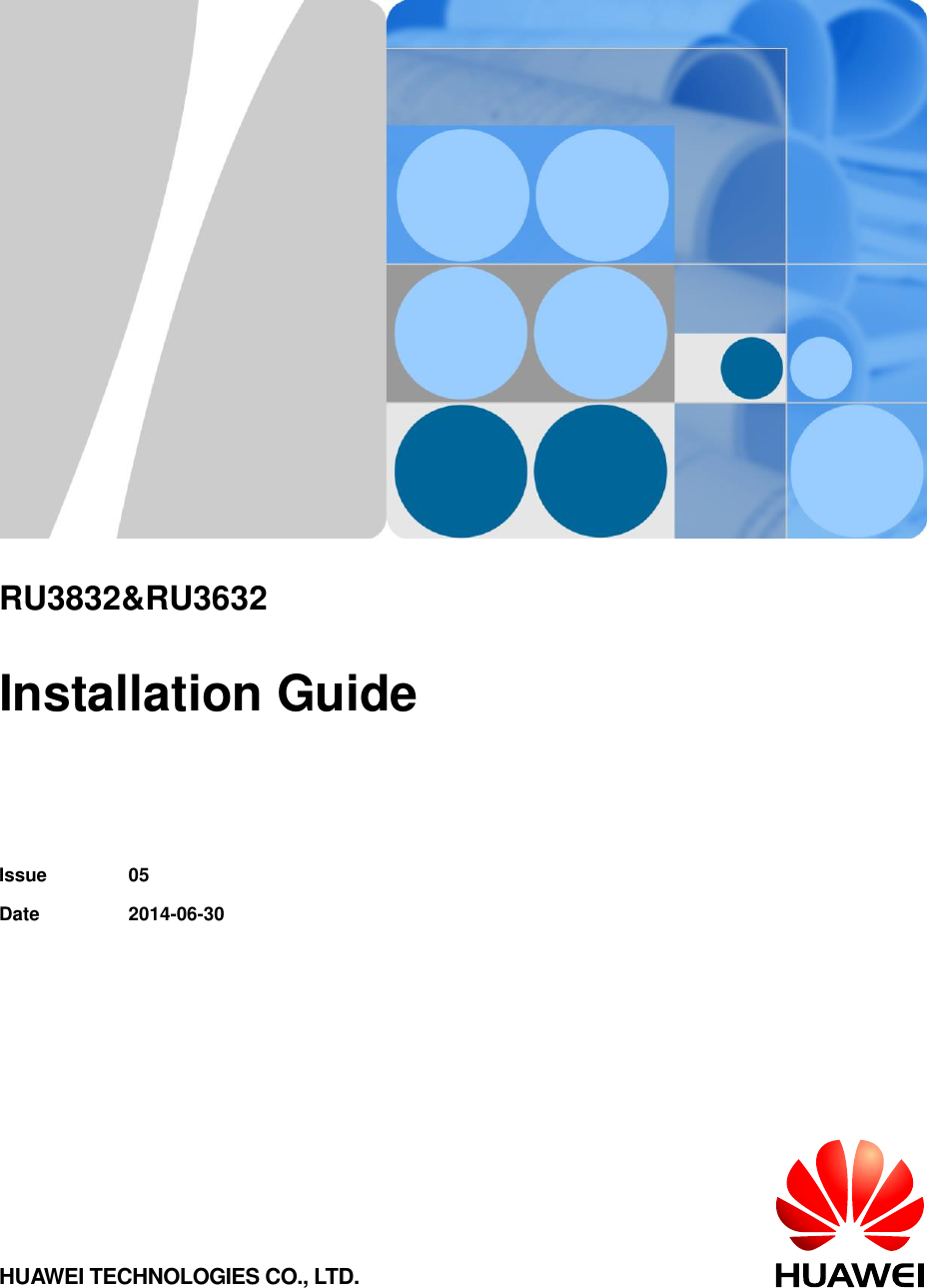
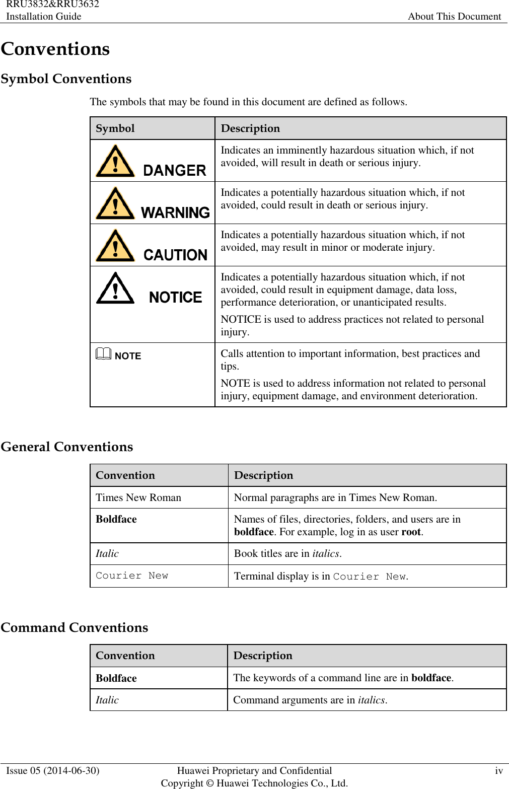
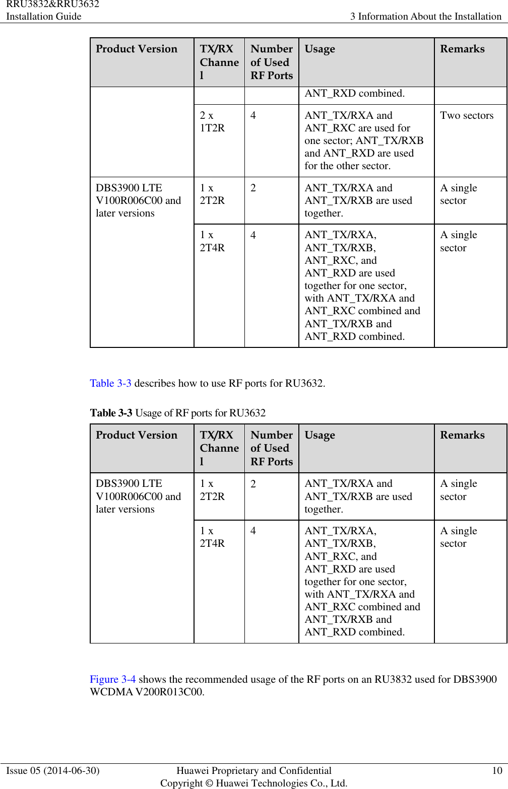
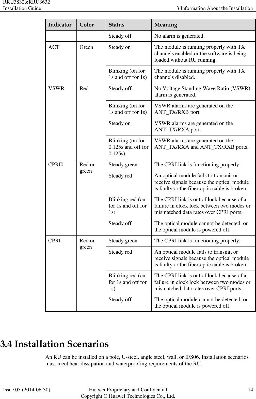
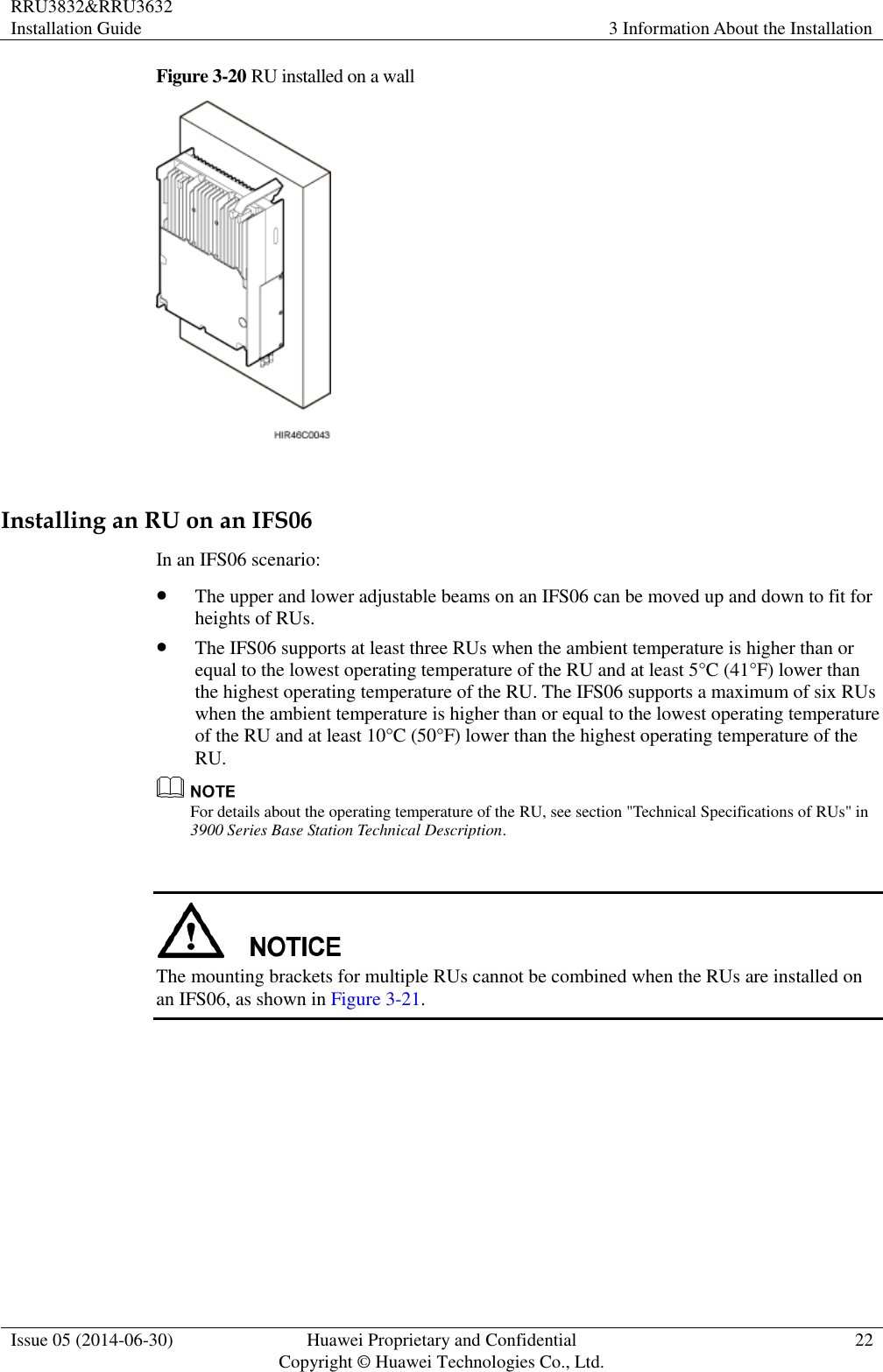
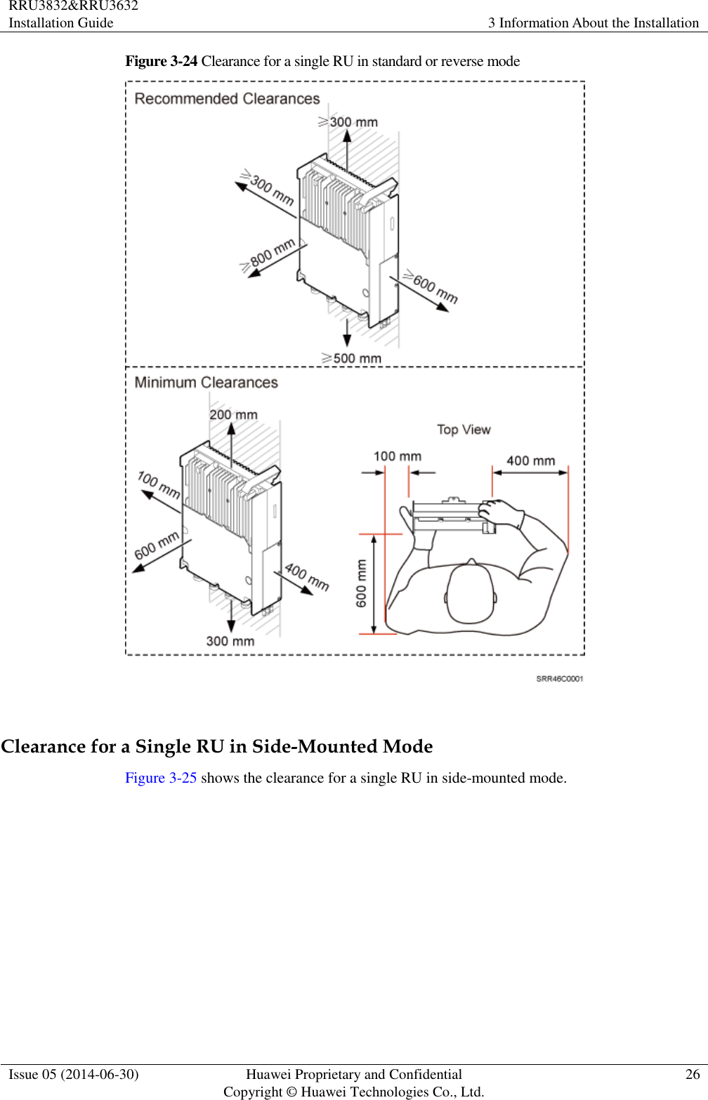
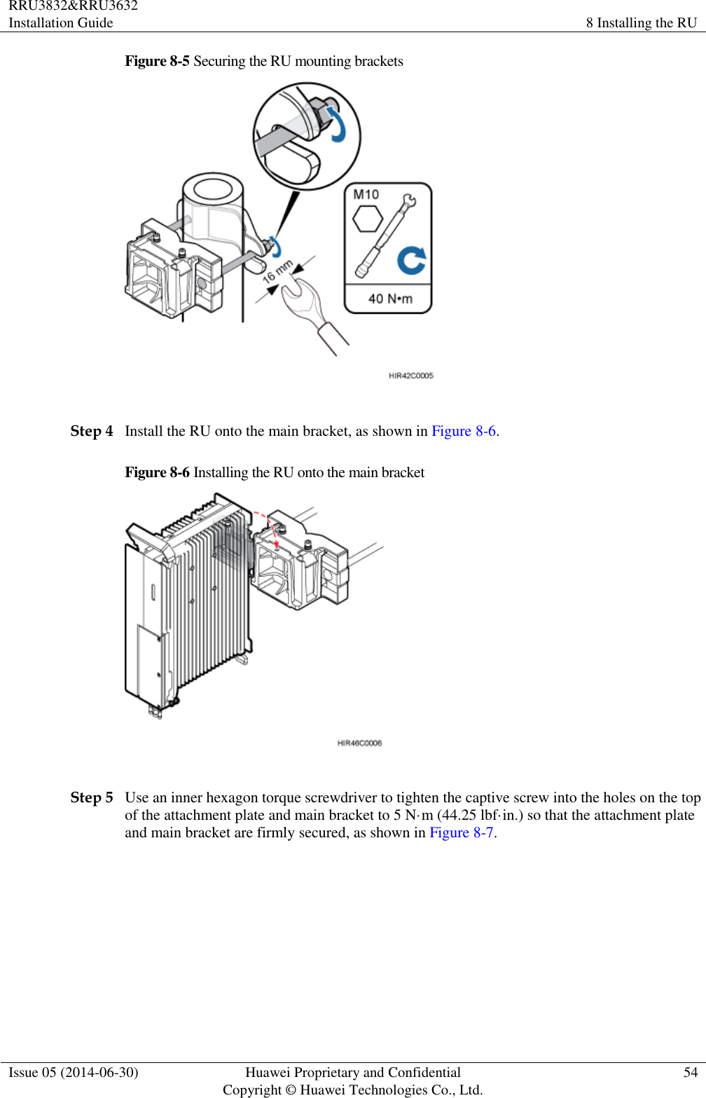
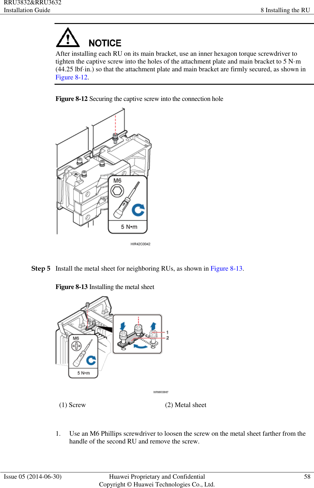
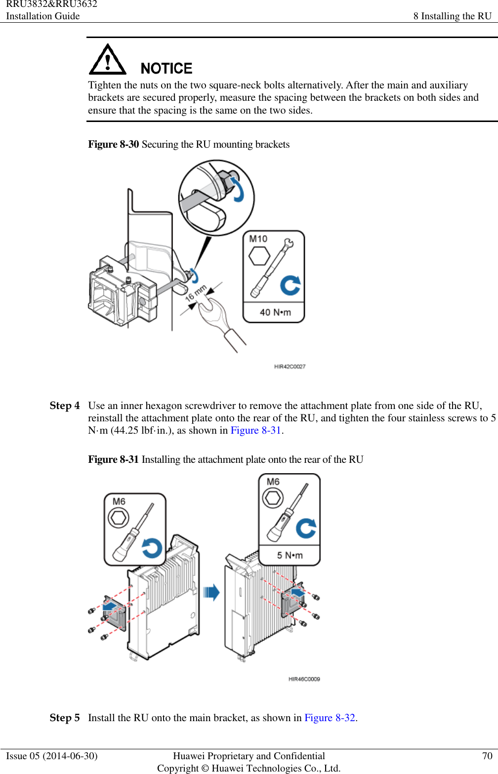
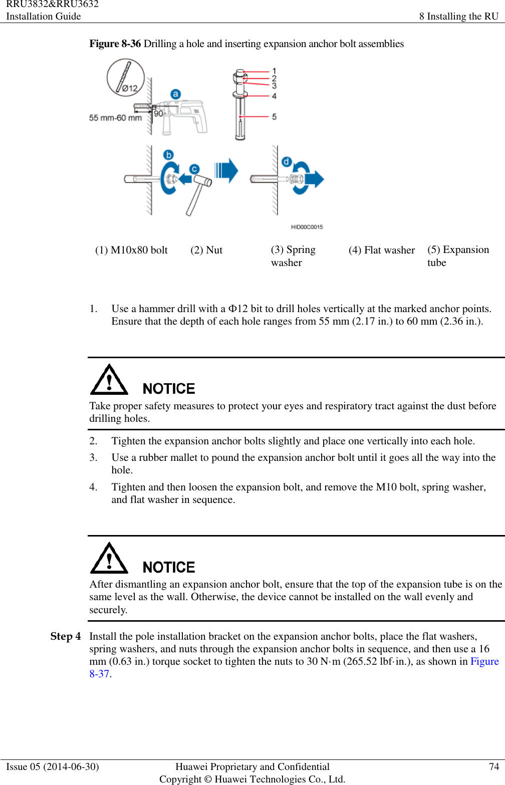
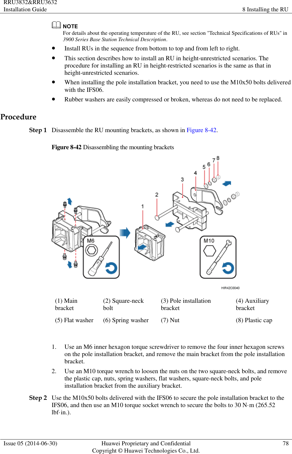
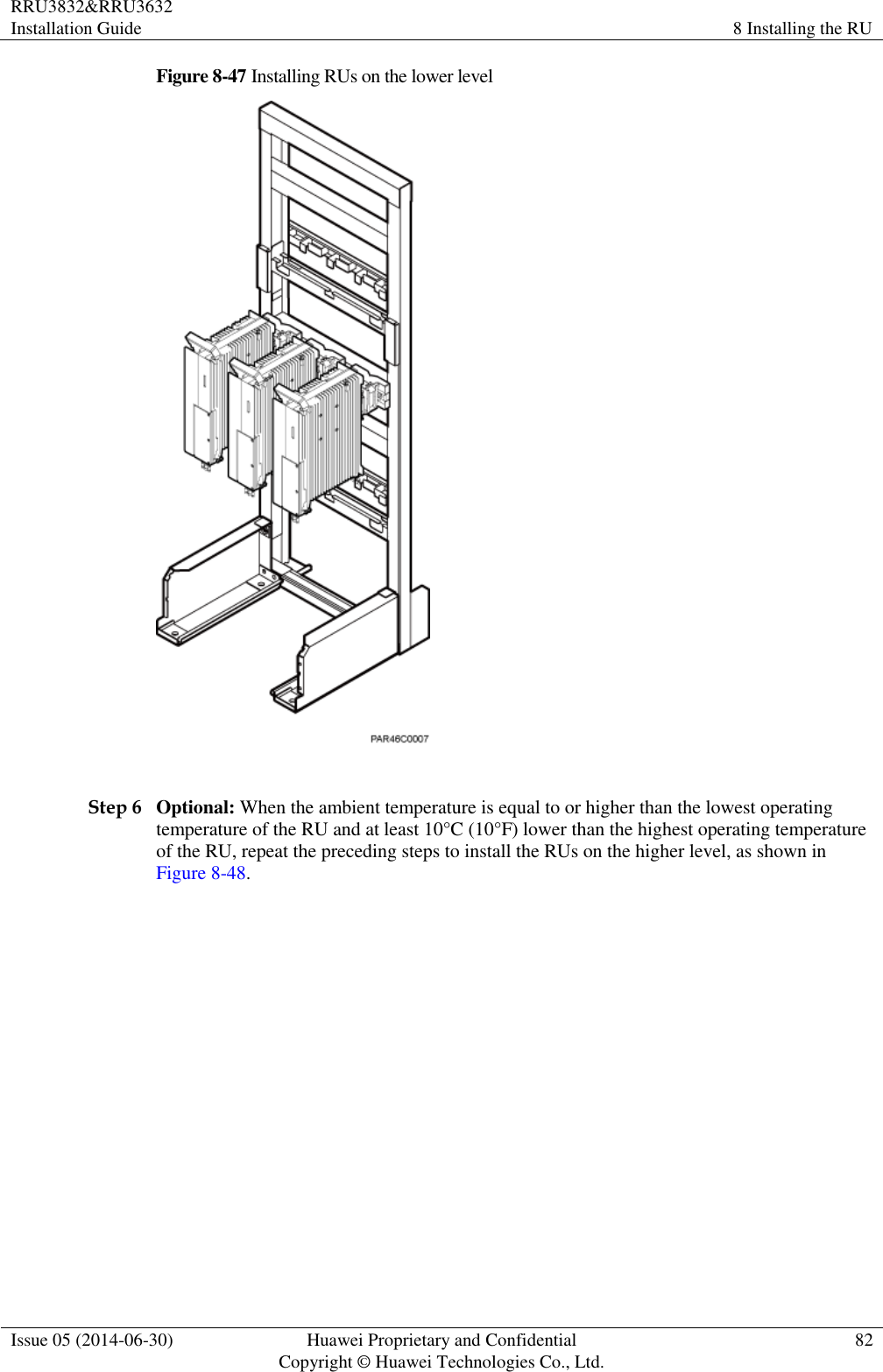
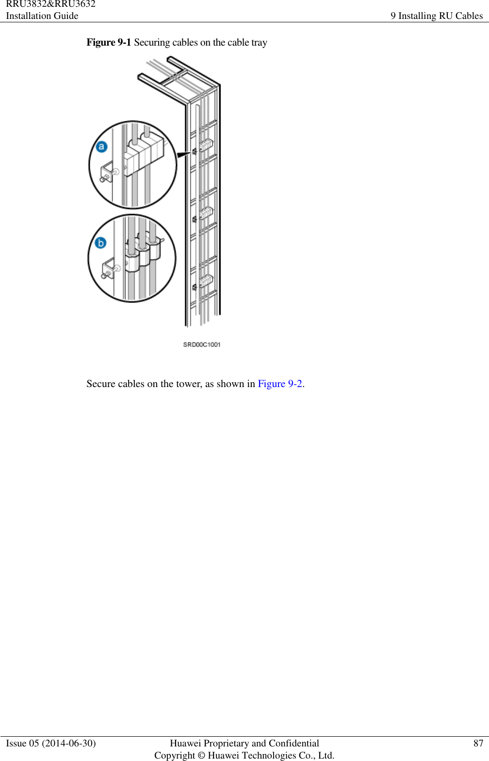
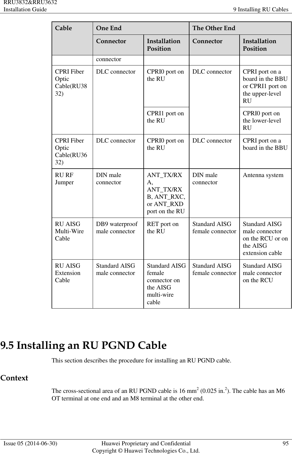
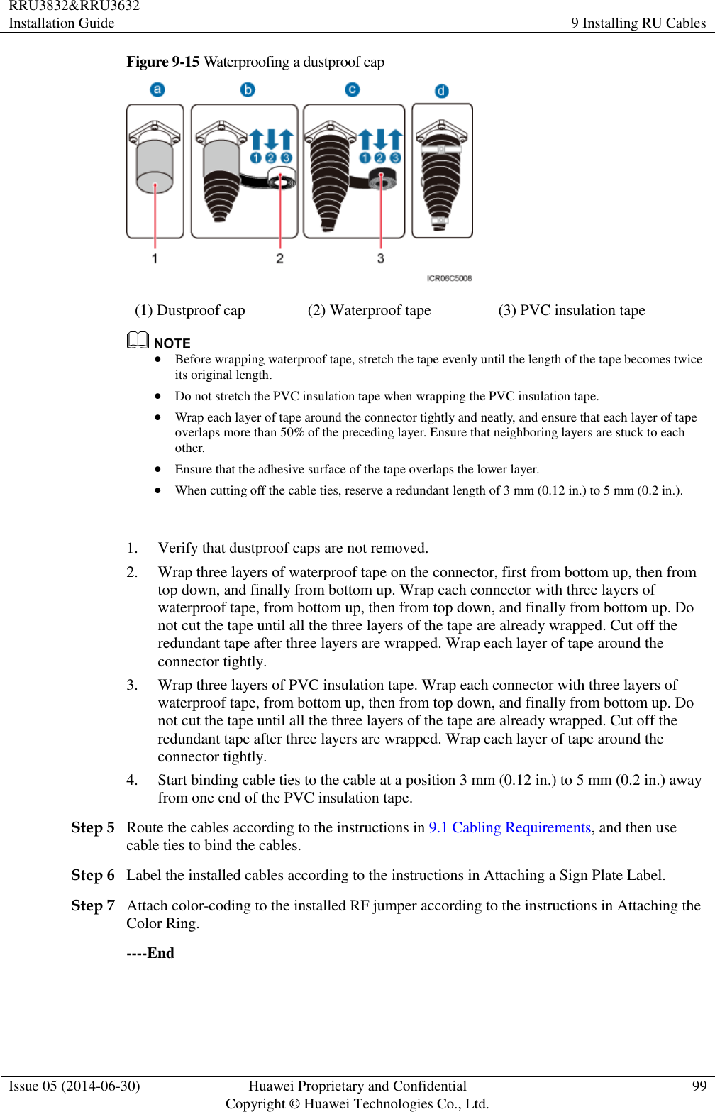
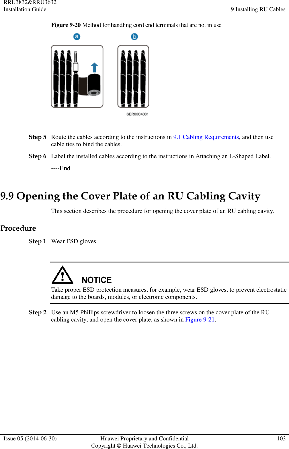
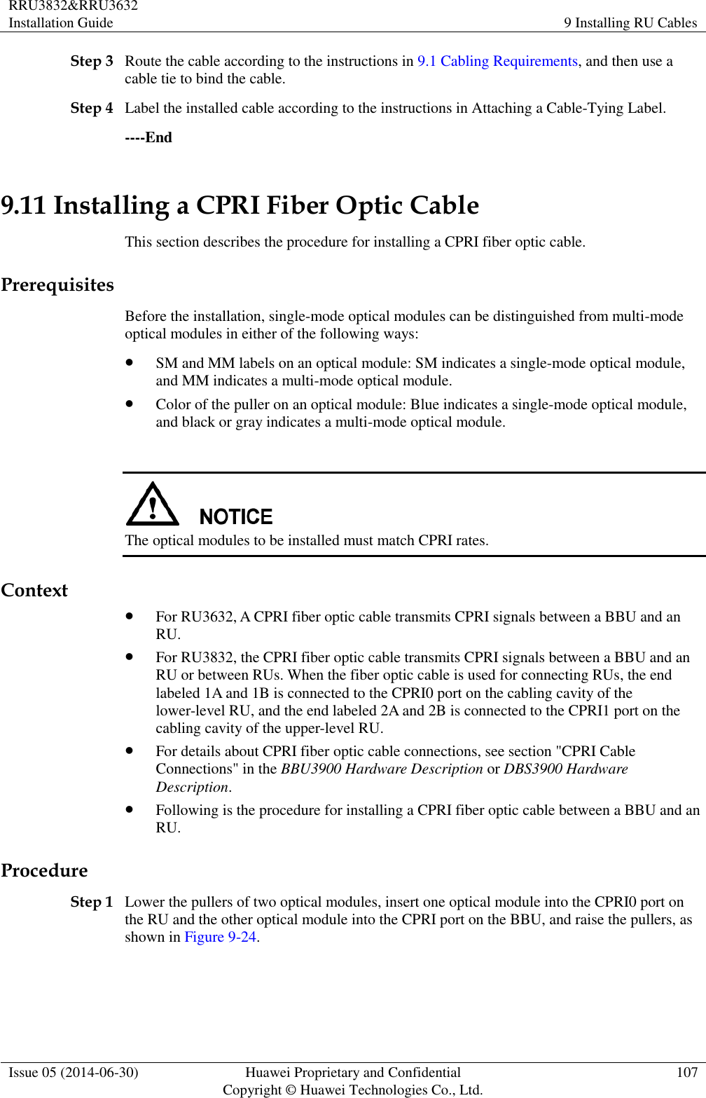
![RRU3832&RRU3632 Installation Guide 2 Installation Preparations Issue 05 (2014-06-30) Huawei Proprietary and Confidential Copyright © Huawei Technologies Co., Ltd. 4 Heat gun Phillips screwdriver (M3 to M6) Flat-head screwdriver (M3 to M6) Rubber mallet COAX crimping tool Wire stripper Utility knife Cable cutter Adjustable wrench (size ≥ 32 mm [1.26 in.]) Torque wrench Size: 16 mm (0.63 in.) and 32 mm (1.26 in.) Combination wrench Size: 16 mm (0.63 in.) and 32 mm (1.26 in.) Level Torque screwdriver 5 mm 5 mm (M3 to M6) (M3 to M6) Torque socket Multimeter Marker (diameter ≤ 10 mm [0.39 in.]) Measuring tape Inner hexagon wrench Fixed pulley Lifting sling](https://usermanual.wiki/Huawei-Technologies/RU3832.User-manual-II/User-Guide-2407260-Page-13.png)
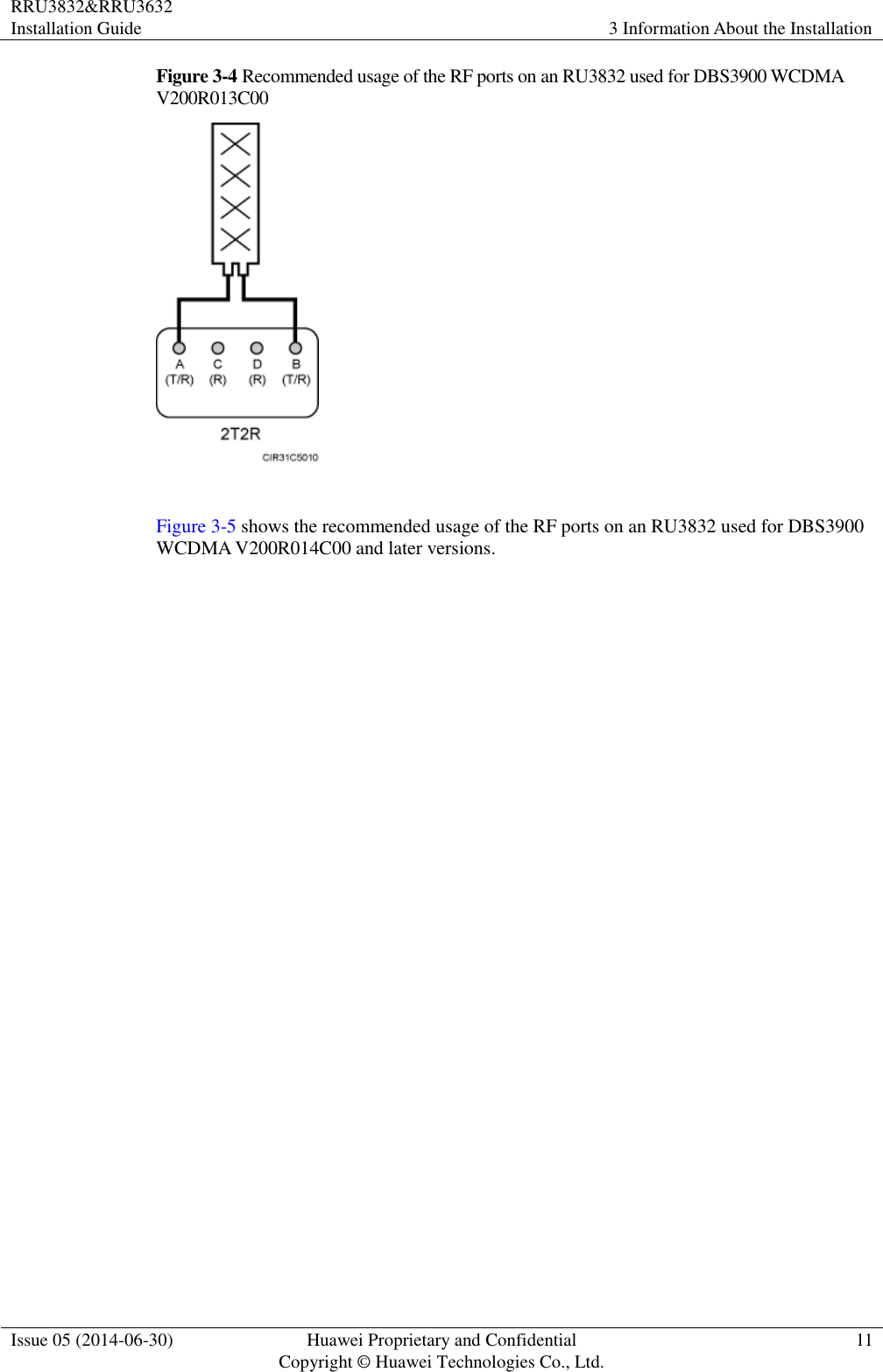
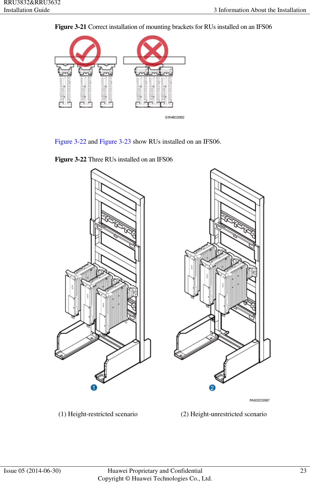
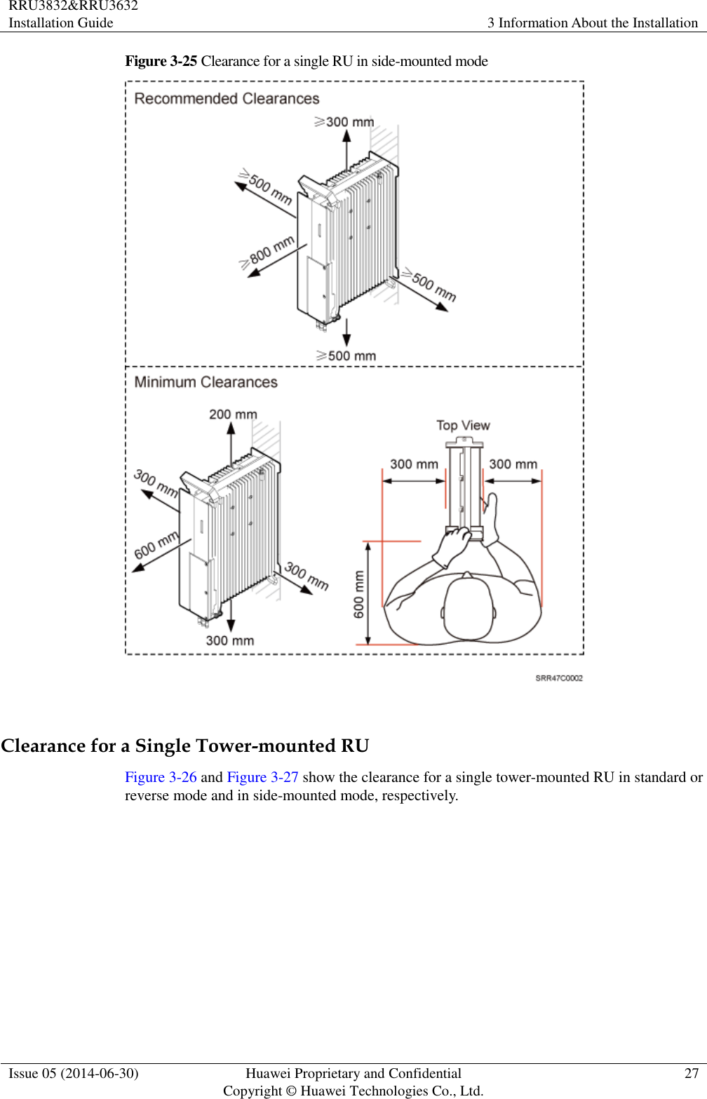
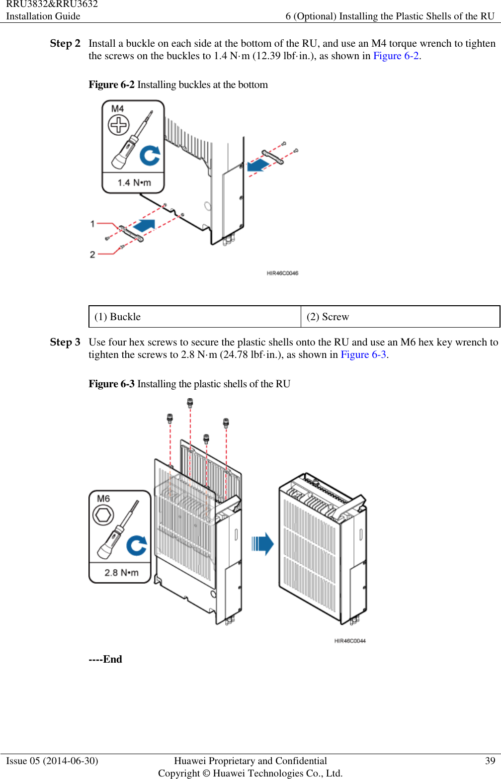
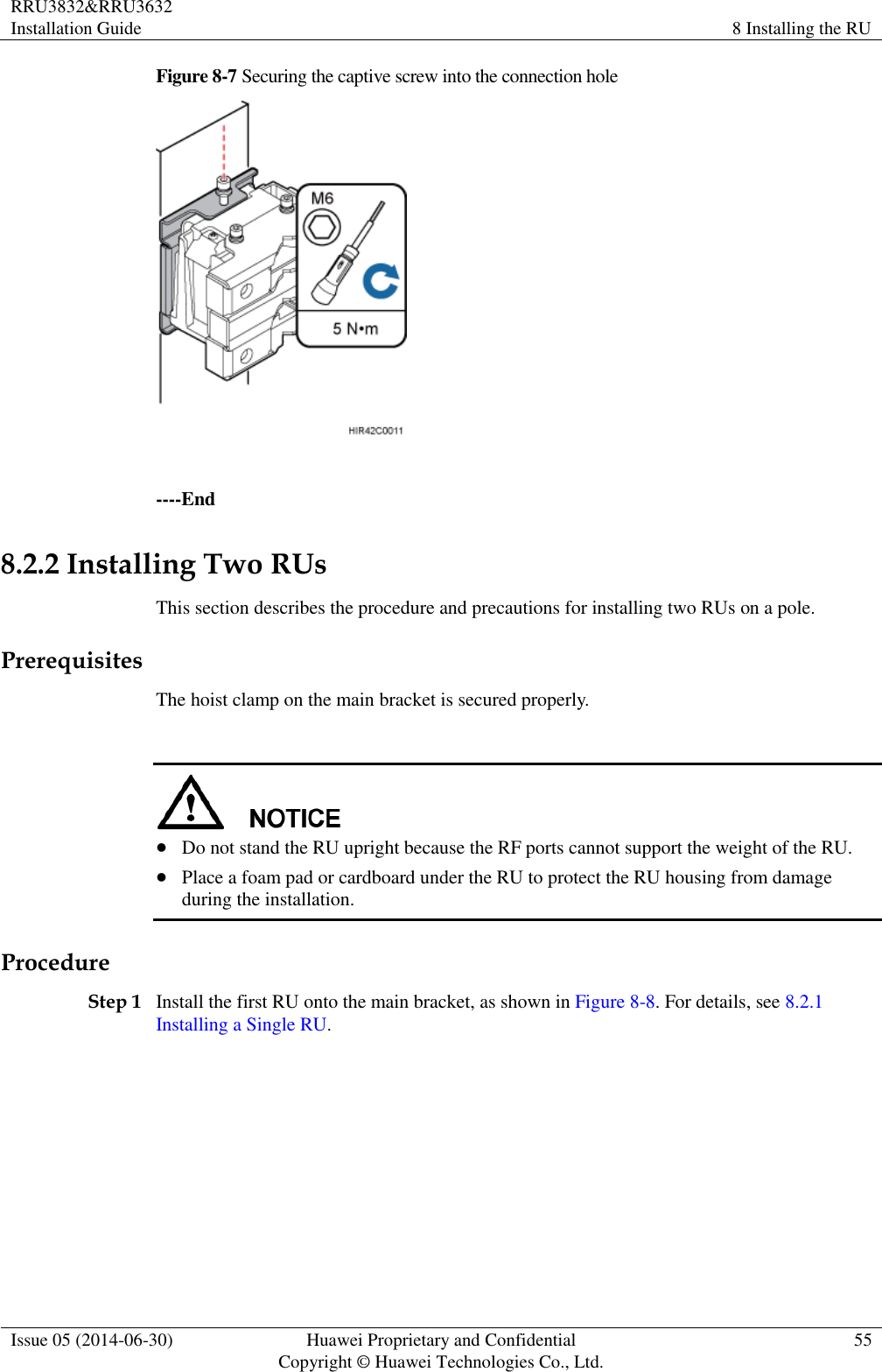
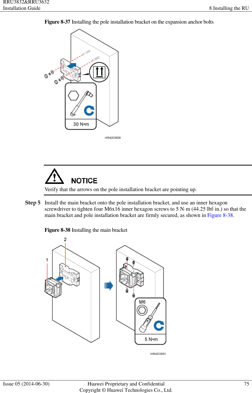
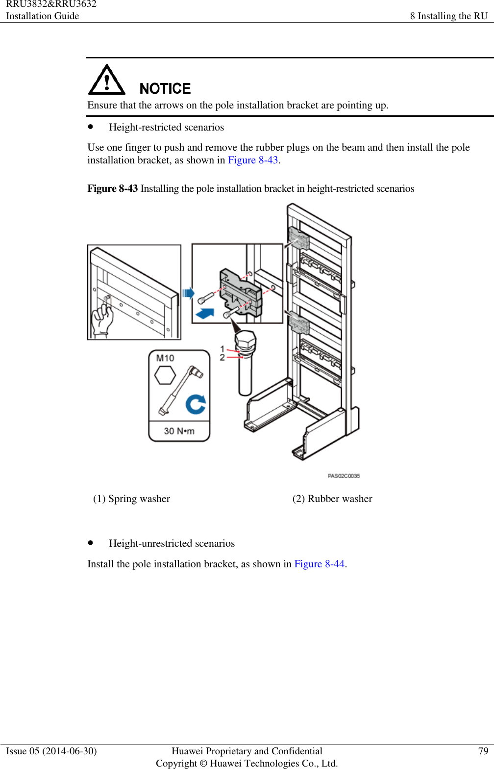
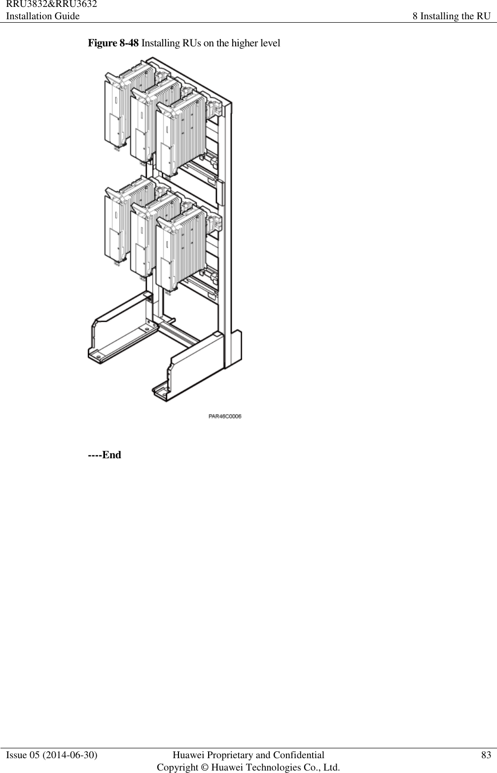
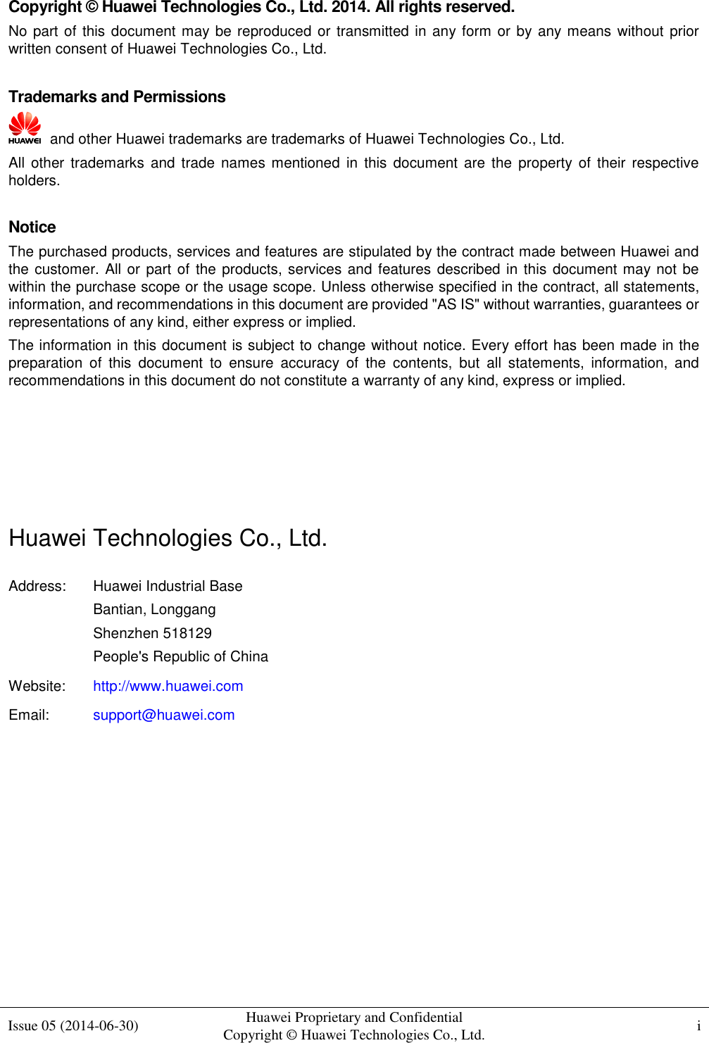
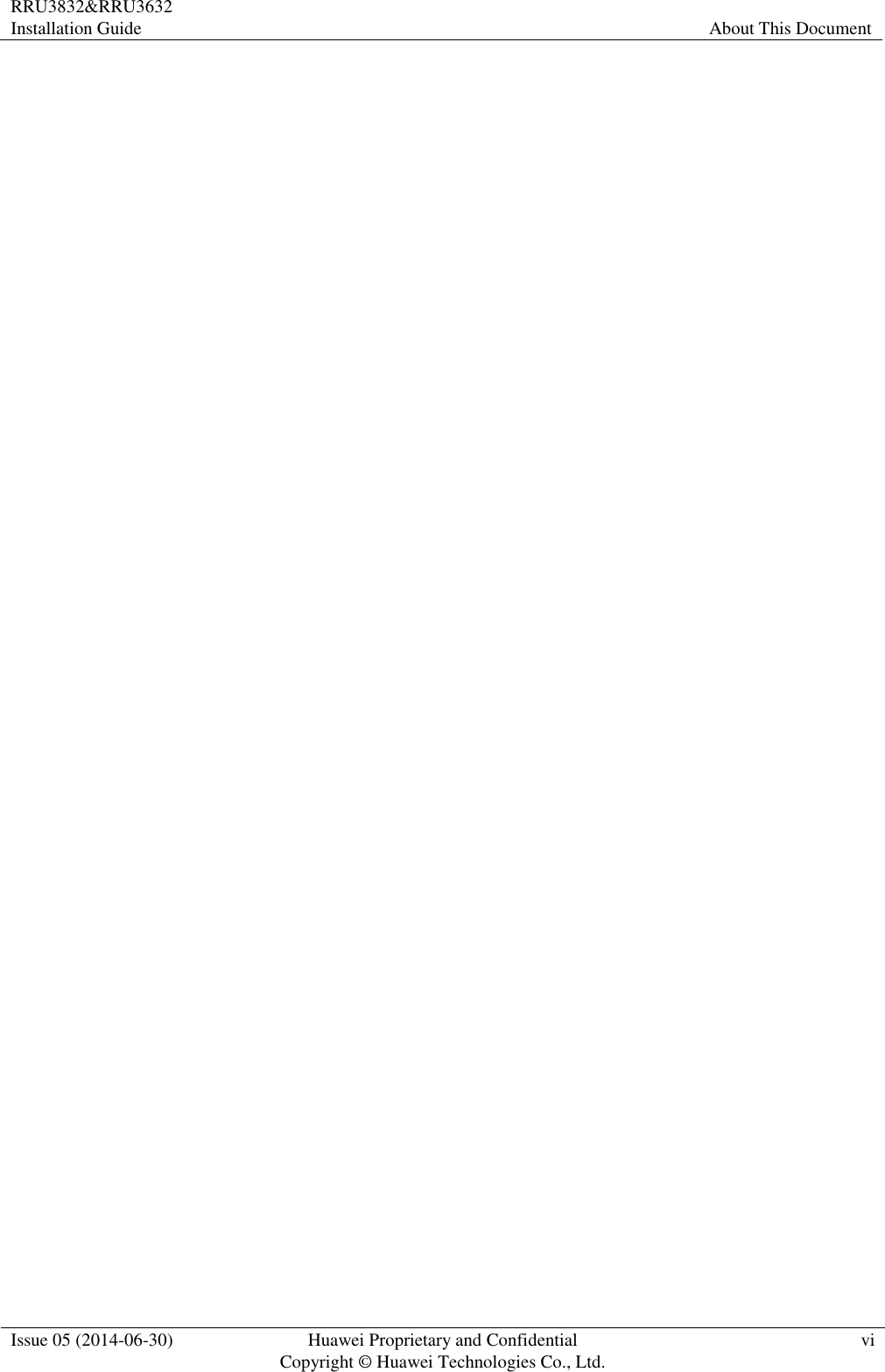
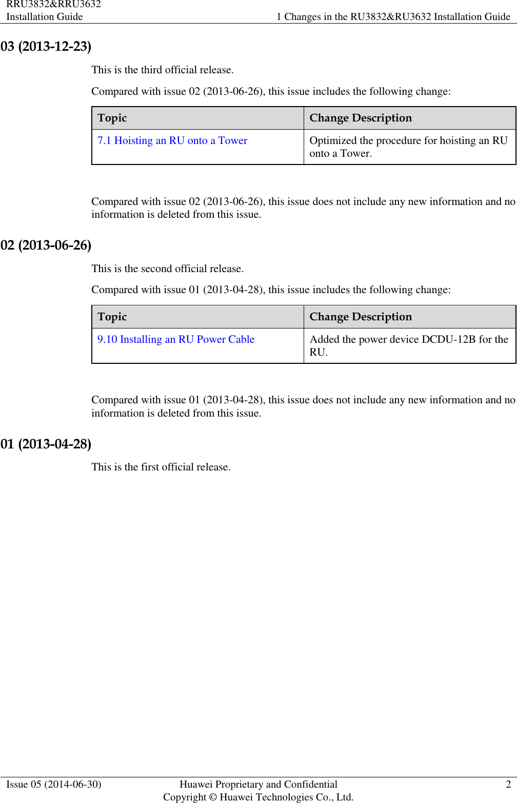
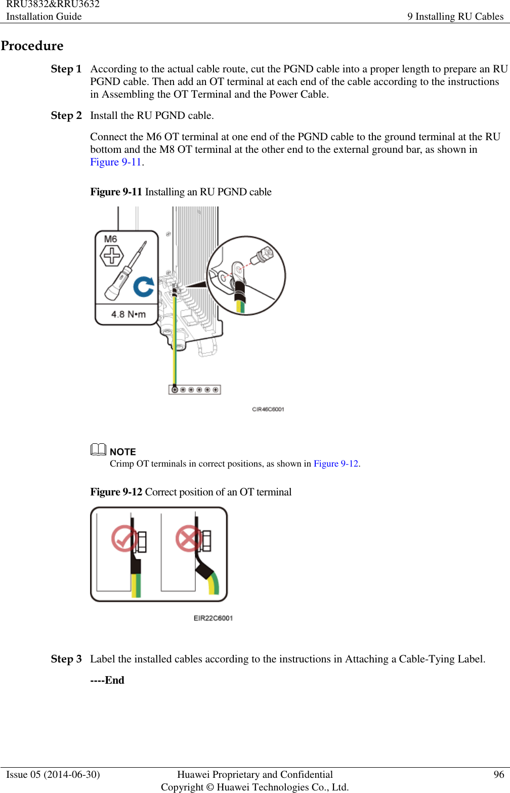
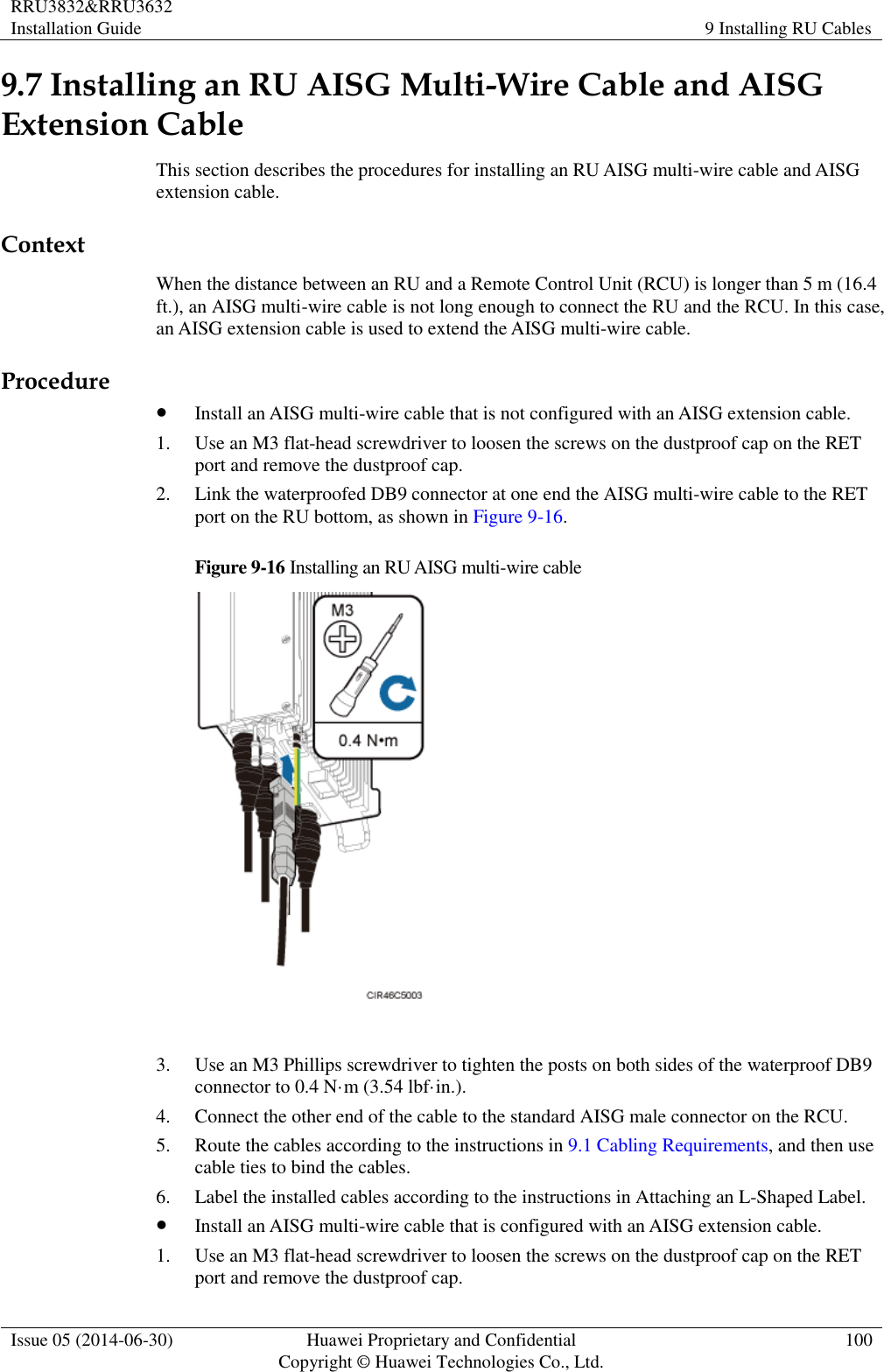
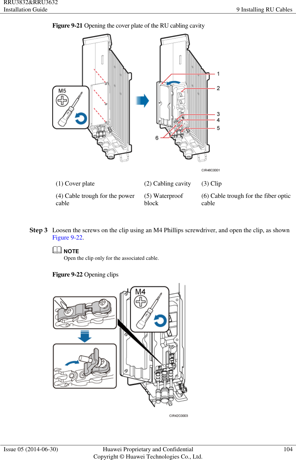
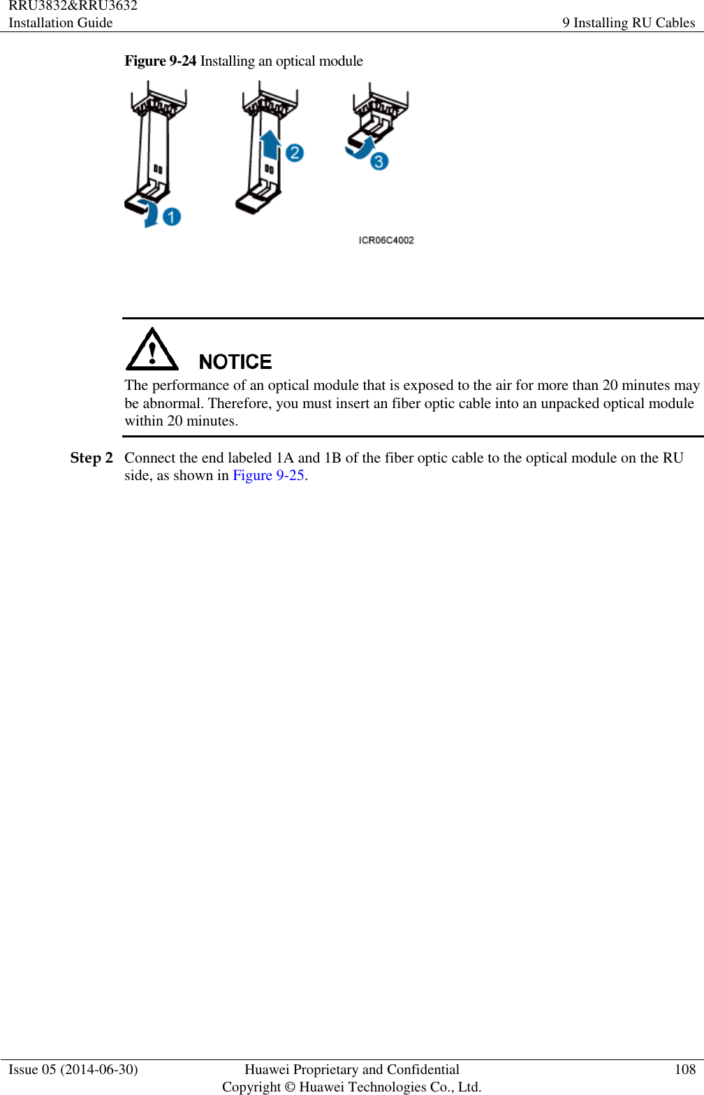
![RRU3832&RRU3632 Installation Guide 9 Installing RU Cables Issue 05 (2014-06-30) Huawei Proprietary and Confidential Copyright © Huawei Technologies Co., Ltd. 86 Cables must be routed away from heat sources, or heat-insulation materials are added between cables and heat sources. Sufficient slack (recommended for about 0.1 m [0.33 ft]) is provided in cables at turns or the position close to a device, facilitating cable and device maintenance. Indoor Cabling Requirements Cables are routed indoors through the feeder window. Drip loops must be made outside the feeder window, and the requirements for the minimum bending radius are met. When cables are routed indoors, engineers are required indoors for cooperation. The feeder window must be waterproofed. Outdoor Cabling Requirements Cables routed outdoors must be led through a pipe when they may be damaged. AC power cables, transmission cables, and cables buried in the ground must be protected. If cables at the cabinet bottom need to be routed through a pipe along the ground, lead the pipe into the cabinet base for about 30 mm (1.18 in.) to 50 mm (1.97 in.), not into the cabinet. Block the pipe with waterproof tape or silicon gel, and secure the pipe to the cable hole at the cabinet bottom with metal piece. If cables at the cabinet bottom need to be routed through a pipe along the metal cable trough, do not lead the pipe into the cabinet base. The cable trough must be sealed and routed through the cable hole at the cabinet bottom. When routing RU cables, ensure that the highest positions of the routes of all RU cables (except RF cables and AISG cables) must be lower than the bottom of the RU. Cables are secured with cable clips. Cables are routed neatly along the specified cabling direction and secured with cable clips. The positions for cable clips are determined onsite. For example, the cable clips for the 7/8" feeder are installed at the spacing of 1.5 m (4.92 ft) to 2 m (6.56 ft) in the same direction, and the cable clips for the power cables are installed at the spacing of 1.5 m (4.92 ft) to 2 m (6.56 ft) in the same direction. Cable clips must be vertical with cables, and the cables in a cable clip must be parallel. After routing cables neatly and correctly, tighten the screws on cable clips. Secure cables on the cable tray, as shown in Figure 9-1.](https://usermanual.wiki/Huawei-Technologies/RU3832.User-manual-II/User-Guide-2407260-Page-95.png)
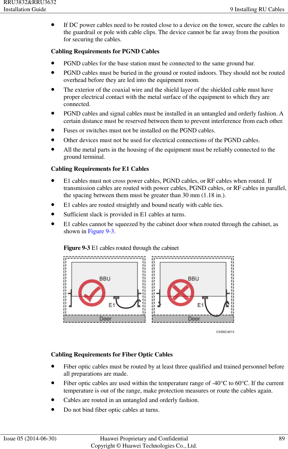
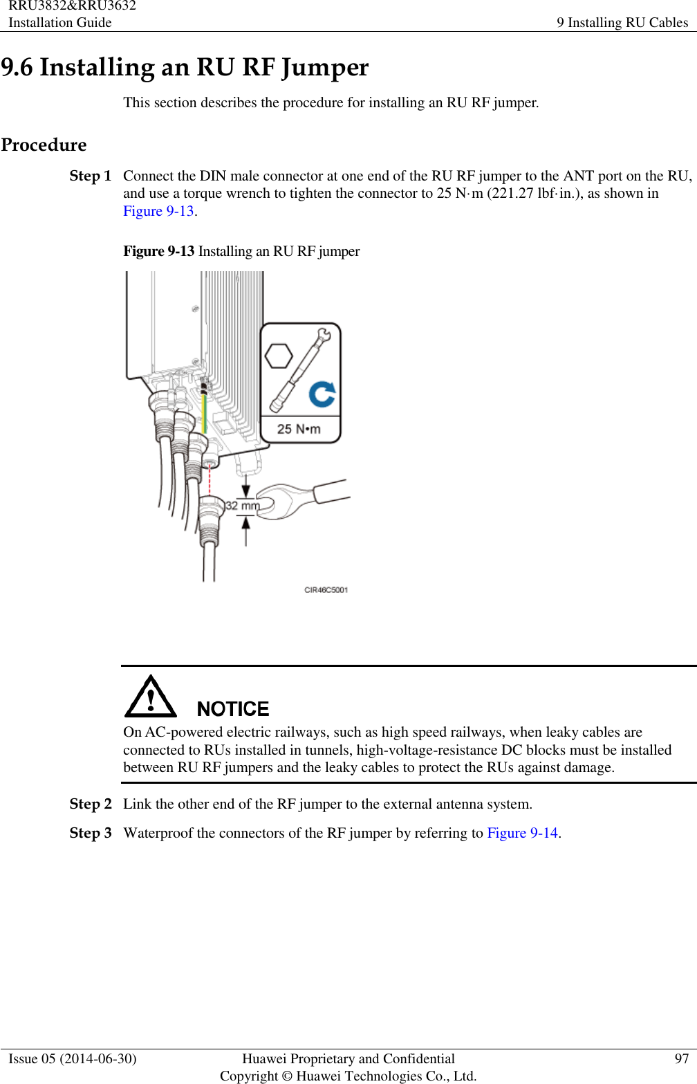
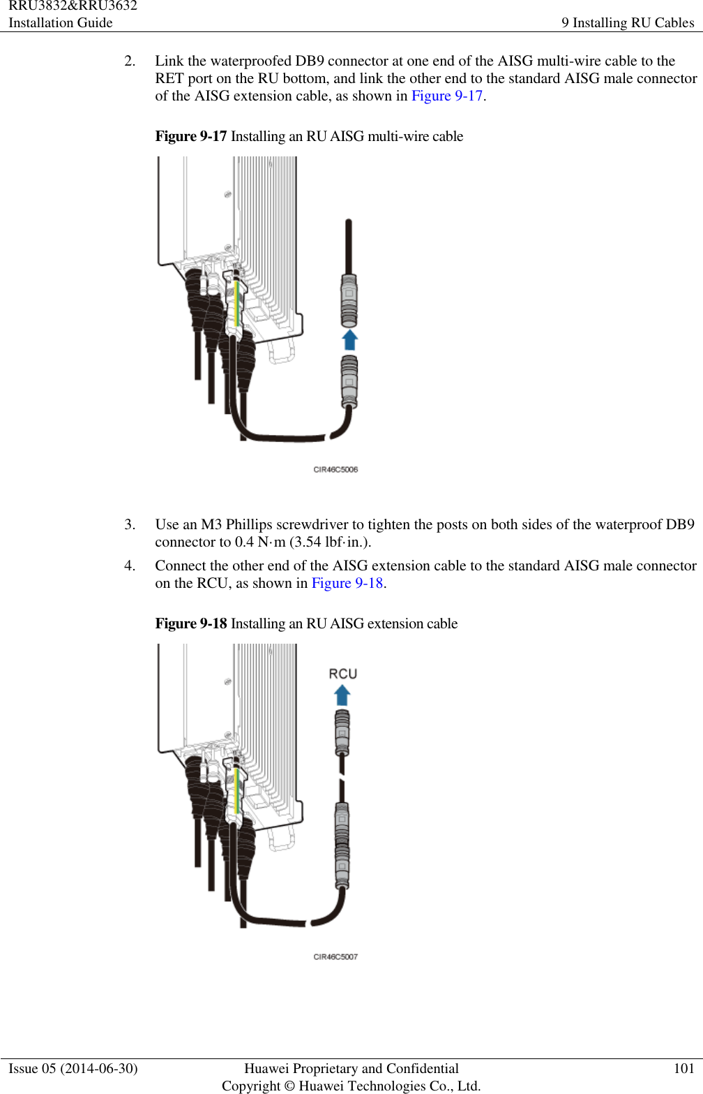
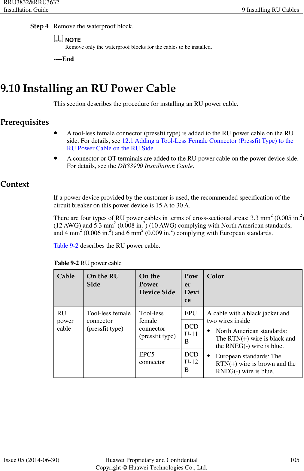
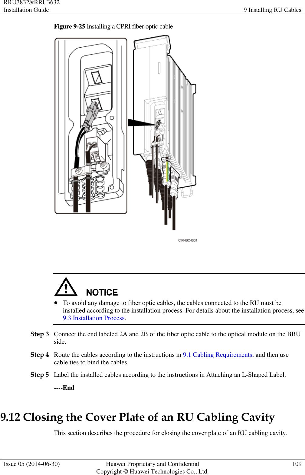
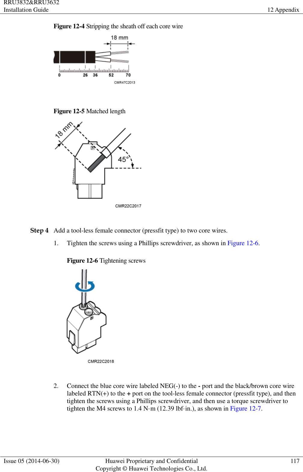
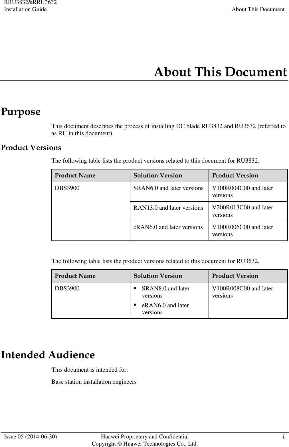
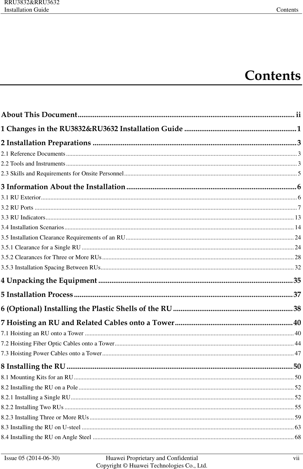
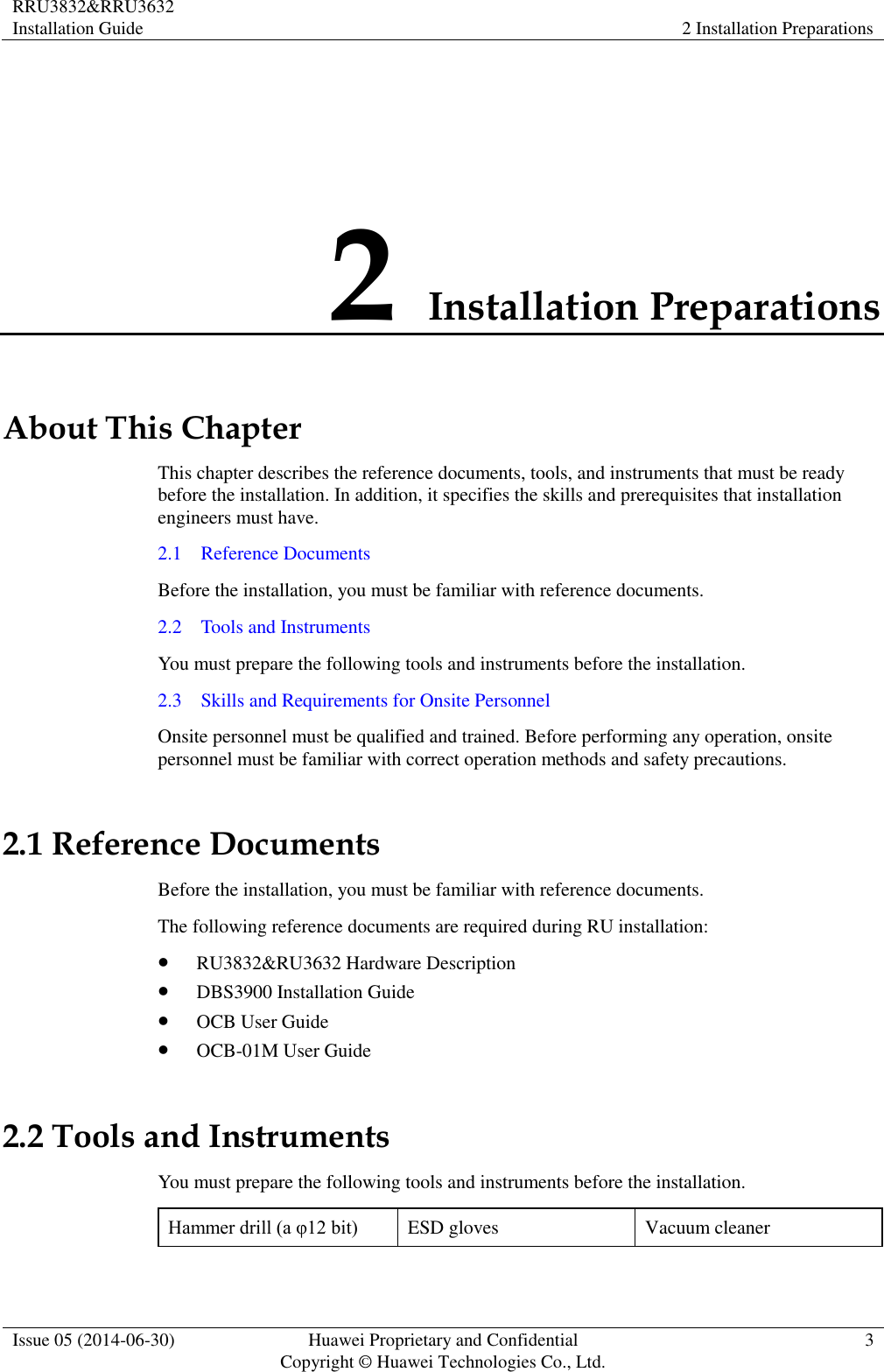
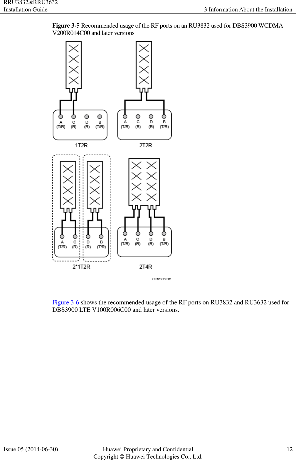
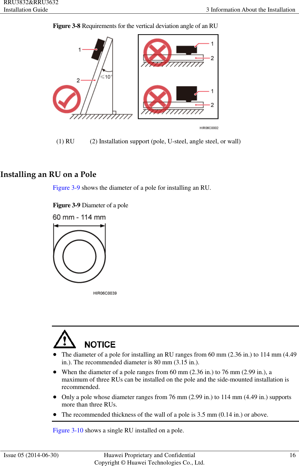
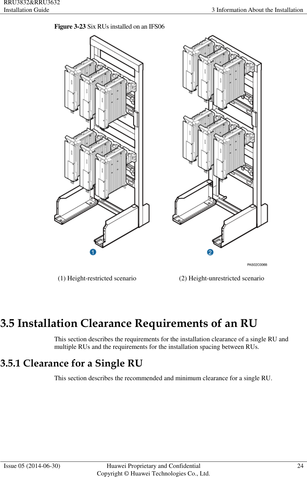
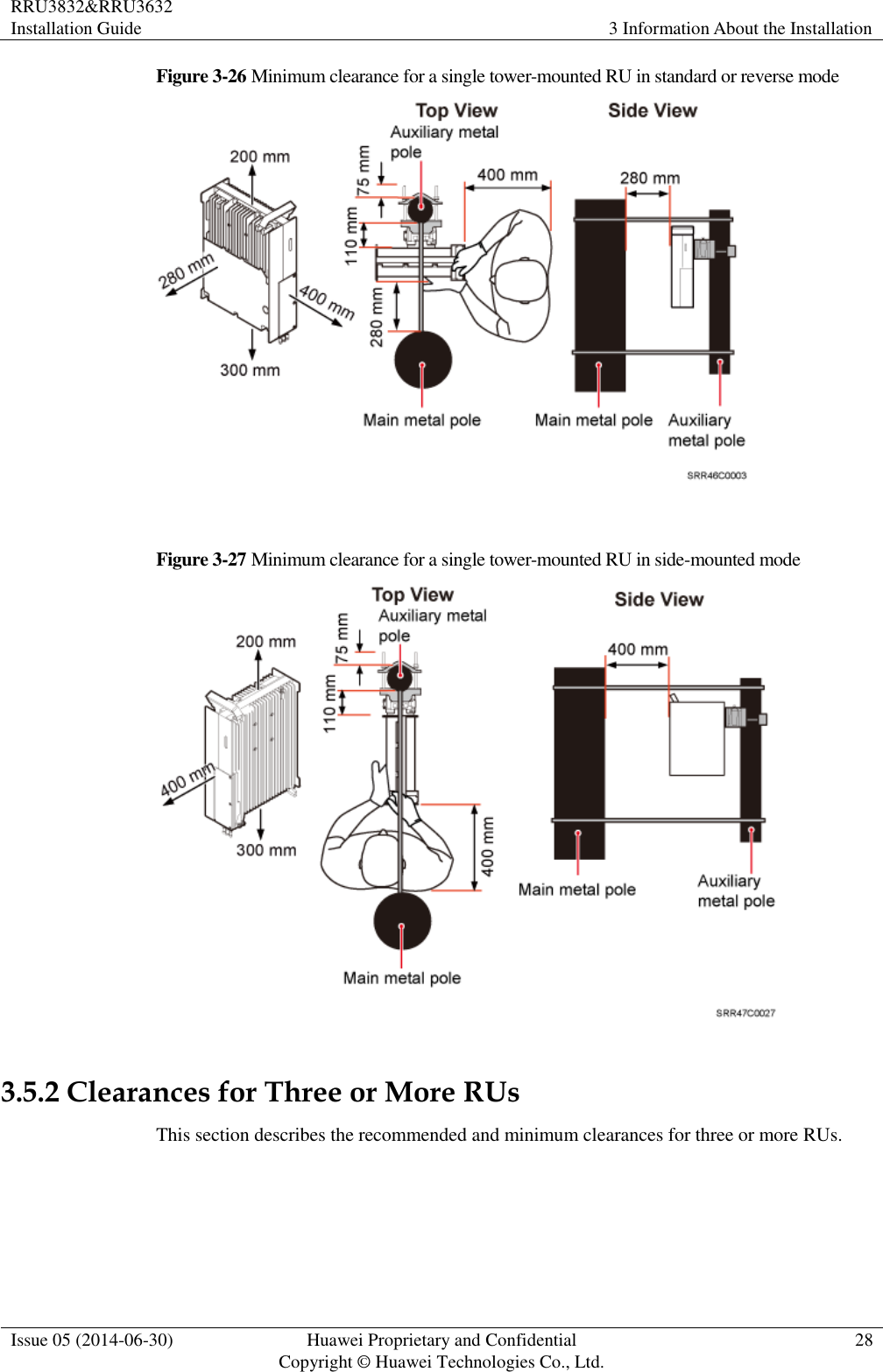
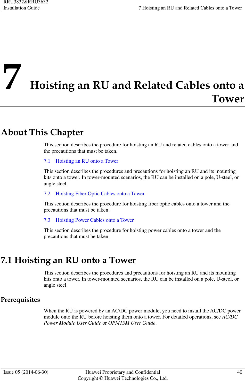
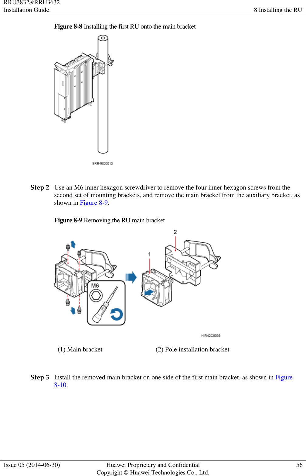
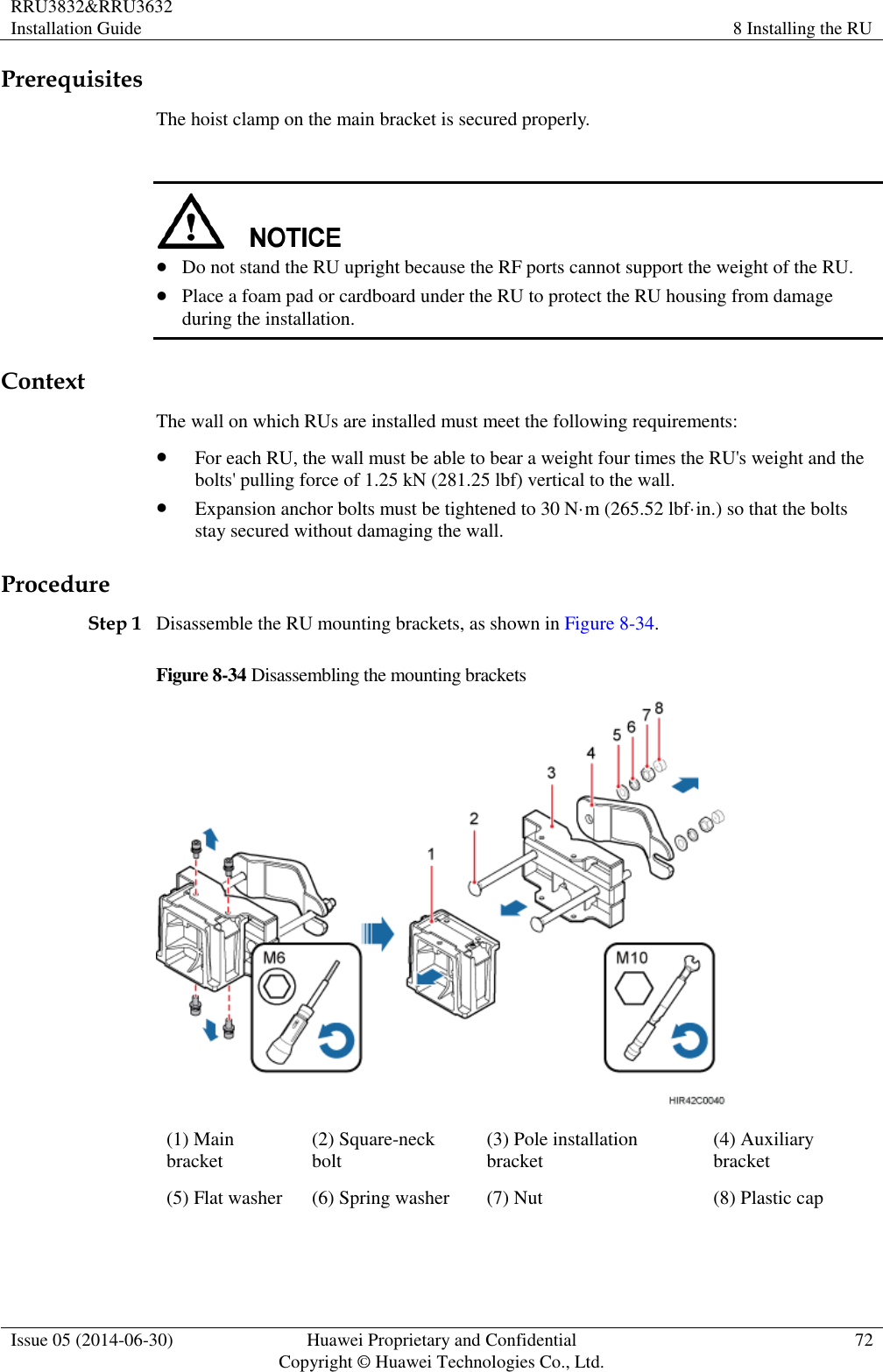
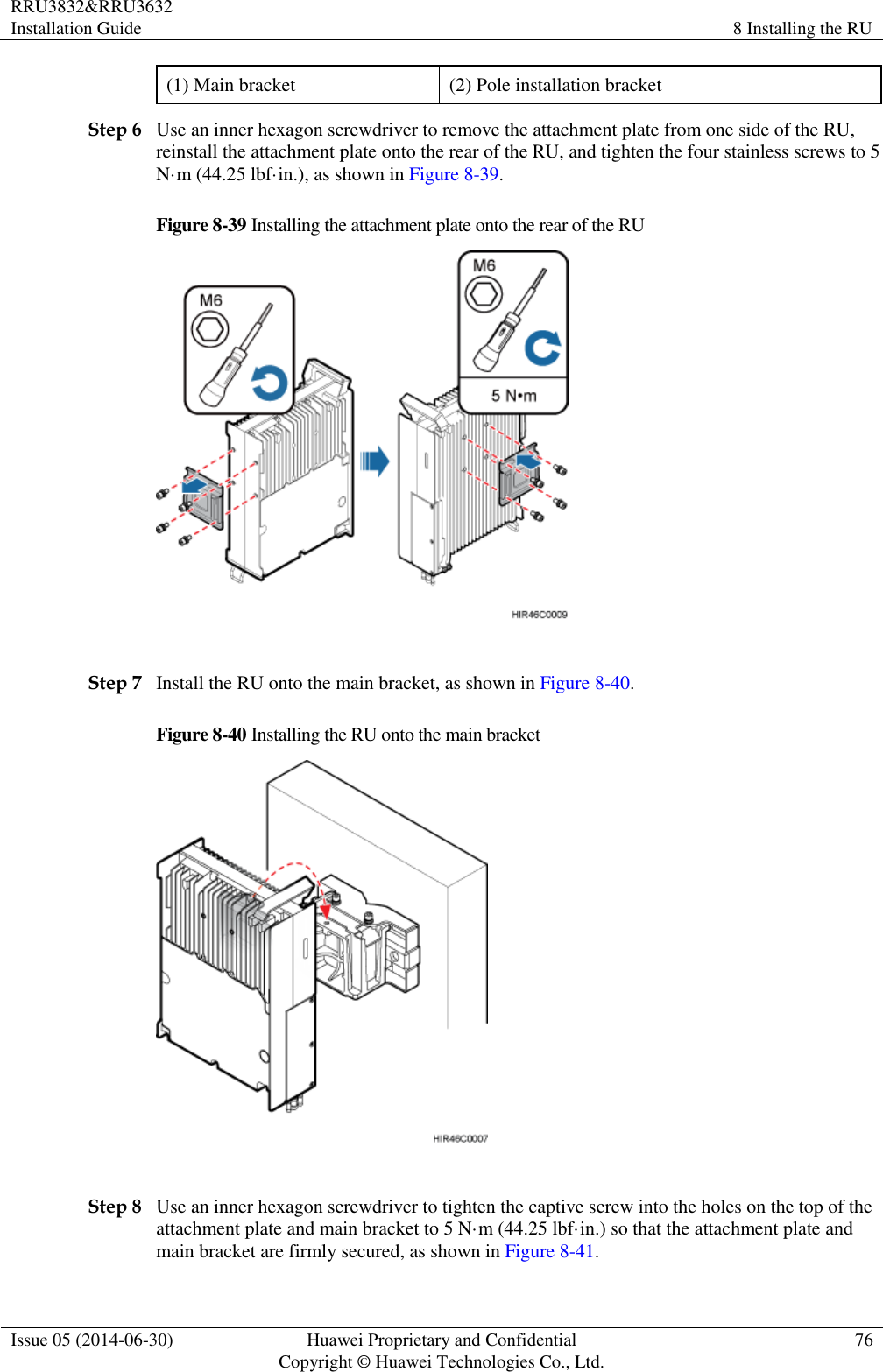
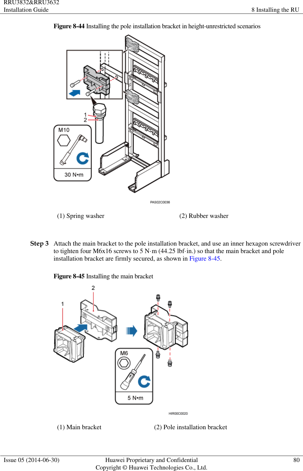
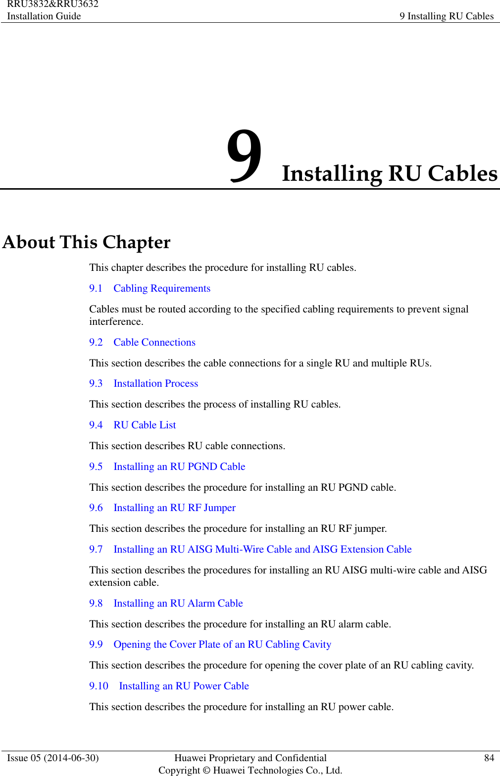
![RRU3832&RRU3632 Installation Guide 12 Appendix Issue 05 (2014-06-30) Huawei Proprietary and Confidential Copyright © Huawei Technologies Co., Ltd. 118 Figure 12-7 Adding a tool-less female connector (pressfit type) to two core wires Step 5 Strip the specified length of the sheath off the power cable to expose the intact shield layer, as shown in Figure 12-8. Figure 12-8 Stripping the sheath off the power cable Each core wire is exposed outside the tool-less female connector (pressfit type) for 1.5 mm (0.059 [in.]), as shown in Figure 12-9.](https://usermanual.wiki/Huawei-Technologies/RU3832.User-manual-II/User-Guide-2407260-Page-127.png)