Hunter Fan TX13 Remote Control for Ceiling Fan and Attached Lamp User Manual 41475 01
Hunter Fan Company Remote Control for Ceiling Fan and Attached Lamp 41475 01
UserManual.wiki
>
Hunter Fan
>
TX13 User Manual
>
User Manual 85095
Contents
1.
User Manual 85094
2.
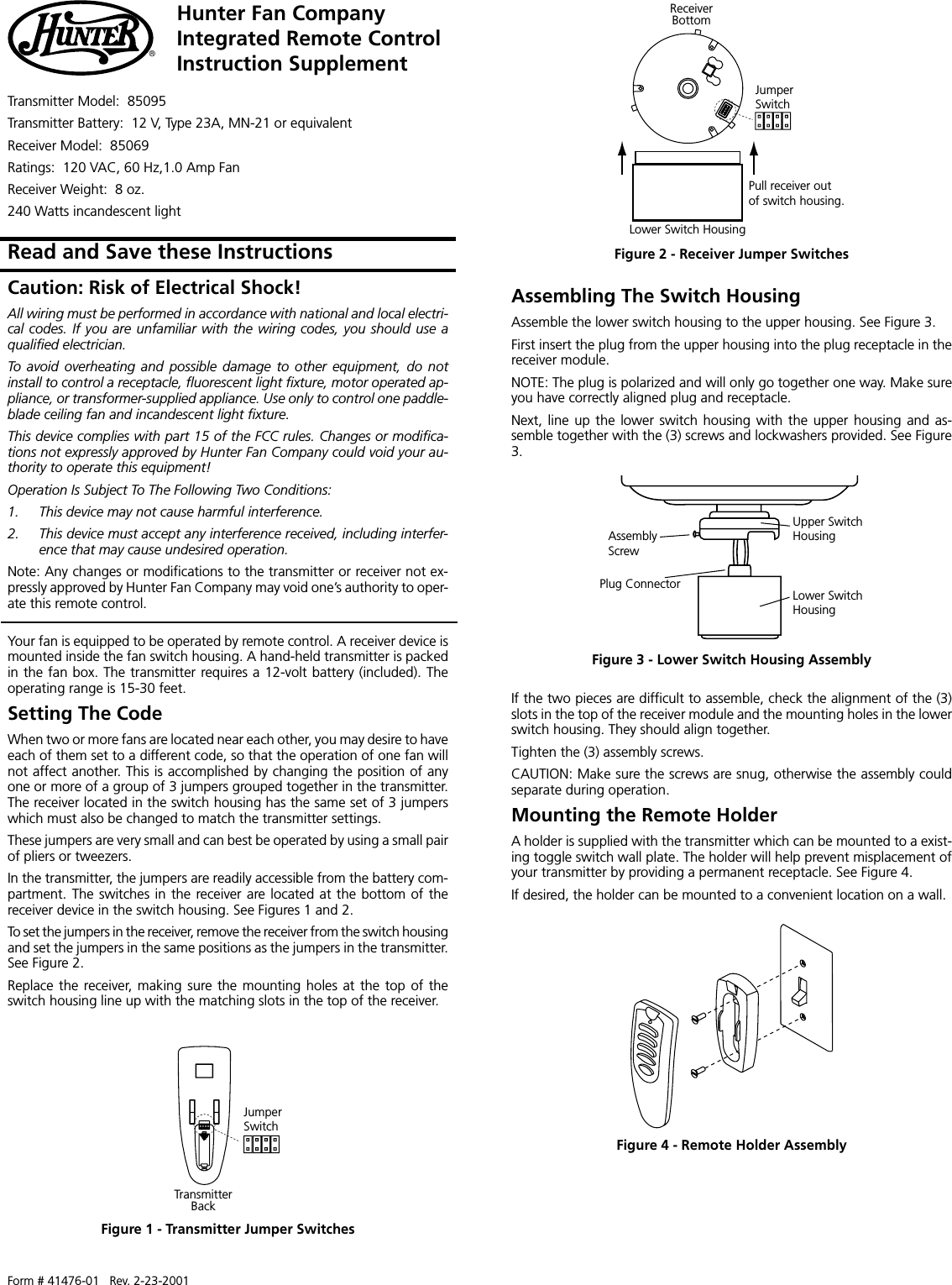
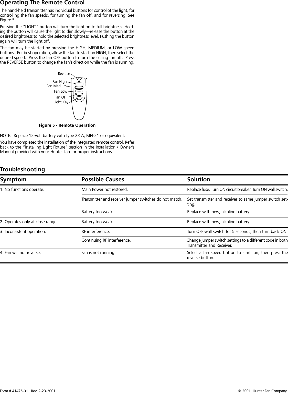
User Manual 85095
User Manual 85095
Navigation menu
Upload a User Manual
Namespaces
Wiki Guide
HTML
PDF
Info
Views
User Manual
Discussion / Help
Navigation