Hunter Fan TX13 Remote Control for Ceiling Fan and Attached Lamp User Manual 41475 01
Hunter Fan Company Remote Control for Ceiling Fan and Attached Lamp 41475 01
Contents
- 1. User Manual 85094
- 2. User Manual 85095
User Manual 85095
Form # 41476-01 Rev. 2-23-2001
Hunter Fan Company
Integrated Remote Control
Instruction Supplement
®
Transmitter Model: 85095
Transmitter Battery: 12 V, Type 23A, MN-21 or equivalent
Receiver Model: 85069
Ratings: 120 VAC, 60 Hz,1.0 Amp Fan
Receiver Weight: 8 oz.
240 Watts incandescent light
Read and Save these Instructions
Your fan is equipped to be operated by remote control. A receiver device is
mounted inside the fan switch housing. A hand-held transmitter is packed
in the fan box. The transmitter requires a 12-volt battery (included). The
operating range is 15-30 feet.
Setting The Code
When two or more fans are located near each other, you may desire to have
each of them set to a different code, so that the operation of one fan will
not affect another. This is accomplished by changing the position of any
one or more of a group of 3 jumpers grouped together in the transmitter.
The receiver located in the switch housing has the same set of 3 jumpers
which must also be changed to match the transmitter settings.
These jumpers are very small and can best be operated by using a small pair
of pliers or tweezers.
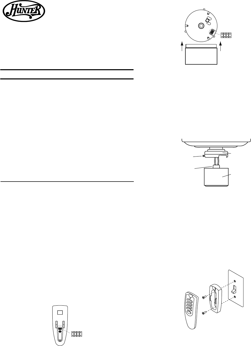
In the transmitter, the jumpers are readily accessible from the battery com-
partment. The switches in the receiver are located at the bottom of the
receiver device in the switch housing. See Figures 1 and 2.
To set the jumpers in the receiver, remove the receiver from the switch housing
and set the jumpers in the same positions as the jumpers in the transmitter.
See Figure 2.
Replace the receiver, making sure the mounting holes at the top of the
switch housing line up with the matching slots in the top of the receiver.
Figure 4 - Remote Holder Assembly
Jumper
Switch
Transmitter
Back
Figure 1 - Transmitter Jumper Switches
Figure 2 - Receiver Jumper Switches
Upper Switch
Housing
Lower Switch
Housing
Plug Connector
Assembly
Screw
Figure 3 - Lower Switch Housing Assembly
If the two pieces are difficult to assemble, check the alignment of the (3)
slots in the top of the receiver module and the mounting holes in the lower
switch housing. They should align together.
Tighten the (3) assembly screws.
CAUTION: Make sure the screws are snug, otherwise the assembly could
separate during operation.
Mounting the Remote Holder
A holder is supplied with the transmitter which can be mounted to a exist-
ing toggle switch wall plate. The holder will help prevent misplacement of
your transmitter by providing a permanent receptacle. See Figure 4.
If desired, the holder can be mounted to a convenient location on a wall.
Assembling The Switch Housing
Assemble the lower switch housing to the upper housing. See Figure 3.
First insert the plug from the upper housing into the plug receptacle in the
receiver module.
NOTE: The plug is polarized and will only go together one way. Make sure
you have correctly aligned plug and receptacle.
Next, line up the lower switch housing with the upper housing and as-
semble together with the (3) screws and lockwashers provided. See Figure
3.
Jumper
Switch
Receiver
Bottom
Lower Switch Housing
Pull receiver out
of switch housing.
Caution: Risk of Electrical Shock!
All wiring must be performed in accordance with national and local electri-
cal codes. If you are unfamiliar with the wiring codes, you should use a
qualified electrician.
To avoid overheating and possible damage to other equipment, do not
install to control a receptacle, fluorescent light fixture, motor operated ap-
pliance, or transformer-supplied appliance. Use only to control one paddle-
blade ceiling fan and incandescent light fixture.
This device complies with part 15 of the FCC rules. Changes or modifica-
tions not expressly approved by Hunter Fan Company could void your au-
thority to operate this equipment!
Operation Is Subject To The Following Two Conditions:
1. This device may not cause harmful interference.
2. This device must accept any interference received, including interfer-
ence that may cause undesired operation.
Note: Any changes or modifications to the transmitter or receiver not ex-
pressly approved by Hunter Fan Company may void one’s authority to oper-
ate this remote control.
Form # 41476-01 Rev. 2-23-2001
Symptom Possible Causes Solution
Troubleshooting
1. No functions operate.
2. Operates only at close range.
3. Inconsistent operation.
Main Power not restored. Replace fuse. Turn ON circuit breaker. Turn ON wall switch.
Transmitter and receiver jumper switches do not match.
Battery too weak.
Set transmitter and receiver to same jumper switch set-
ting.
Replace with new, alkaline battery.
Battery too weak. Replace with new, alkaline battery.
RF interference. Turn OFF wall switch for 5 seconds, then turn back ON.
Continuing RF interference. Change jumper switch settings to a different code in both
Transmitter and Receiver.
© 2001 Hunter Fan Company
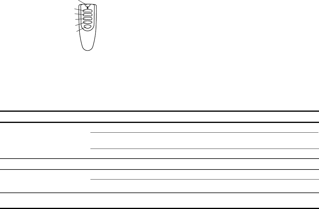
Fan High
Fan Medium
Fan Low
Fan OFF
Light Key
Reverse
Figure 5 - Remote Operation
Operating The Remote Control
The hand-held transmitter has individual buttons for control of the light, for
controlling the fan speeds, for turning the fan off, and for reversing. See
Figure 5.
Pressing the “LIGHT” button will turn the light on to full brightness. Hold-
ing the button will cause the light to dim slowly—release the button at the
desired brightness to hold the selected brightness level. Pushing the button
again will turn the light off.
The fan may be started by pressing the HIGH, MEDIUM, or LOW speed
buttons. For best operation, allow the fan to start on HIGH, then select the
desired speed. Press the fan OFF button to turn the ceiling fan off. Press
the REVERSE button to change the fan’s direction while the fan is running.
NOTE: Replace 12-volt battery with type 23 A, MN-21 or equivalent.
You have completed the installation of the integrated remote control. Refer
back to the “Installing Light Fixture” section in the Installation / Owner’s
Manual provided with your Hunter fan for proper instructions.
4. Fan will not reverse. Fan is not running. Select a fan speed button to start fan, then press the
reverse button.