Hytera Communications PD79XISU1 Is Digital Radio User Manual
Hytera Communications Corporation Limited Is Digital Radio Users Manual
UserManual.wiki
>
Hytera Communications
>
PD79XISU1 User Manual
Users Manual
Navigation menu
Upload a User Manual
Namespaces
Wiki Guide
HTML
PDF
Info
Views
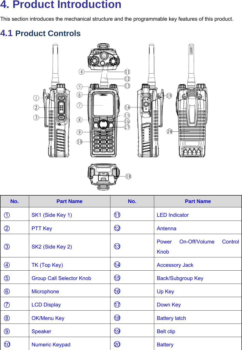
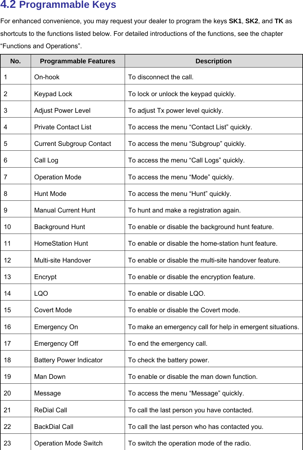
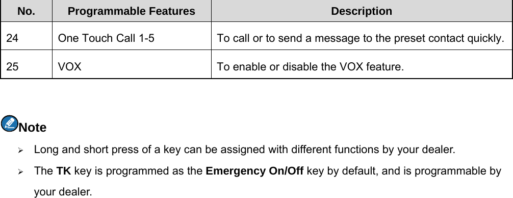
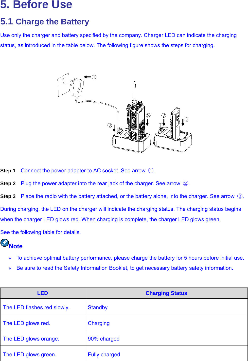
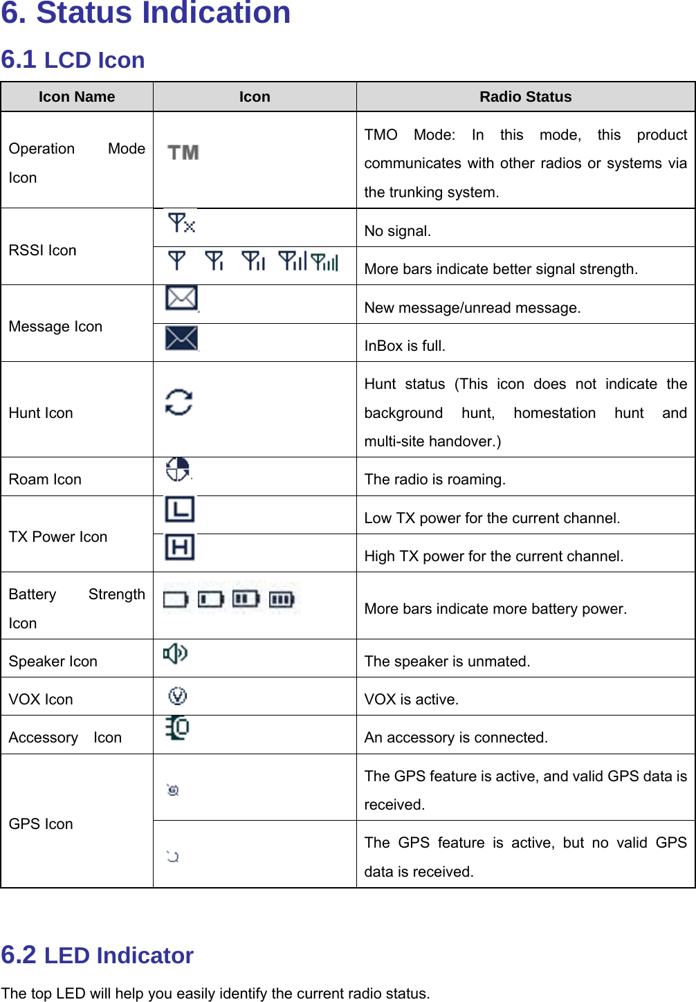
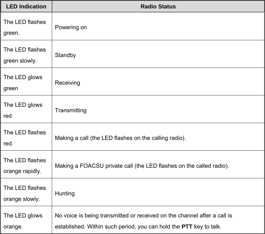
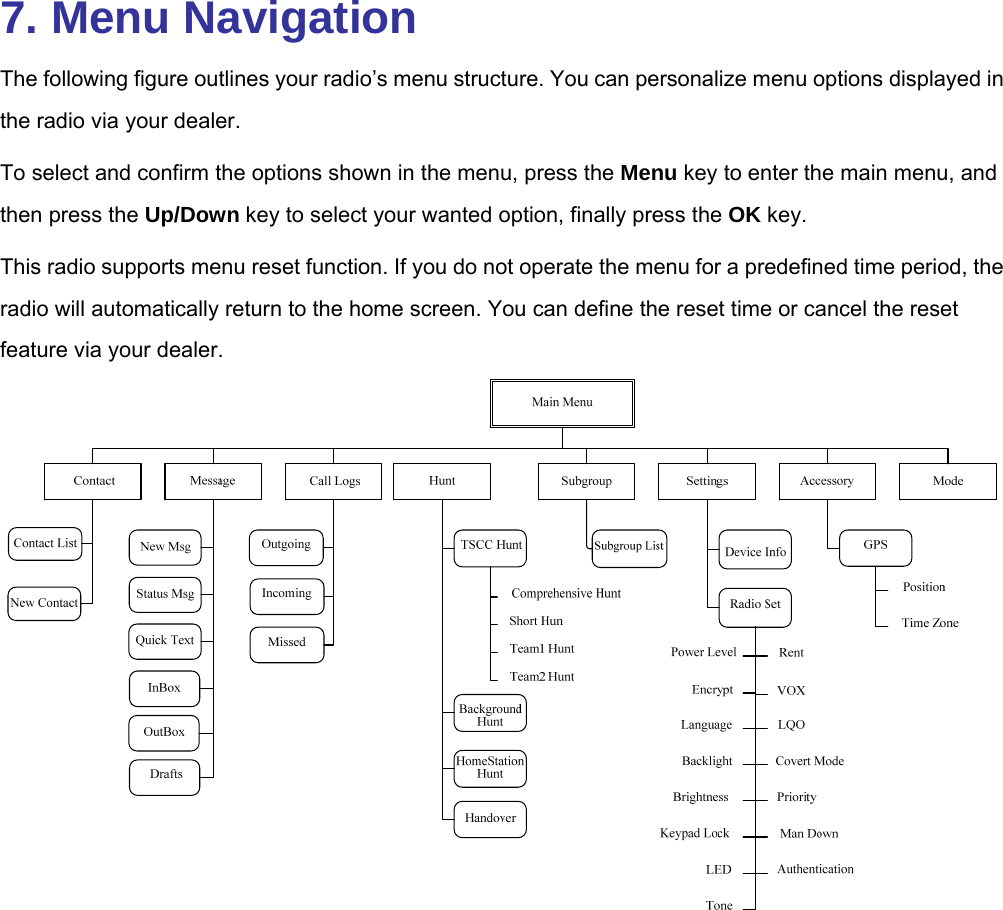
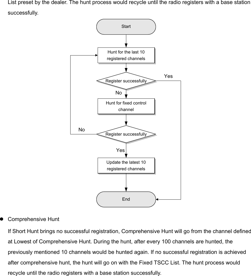
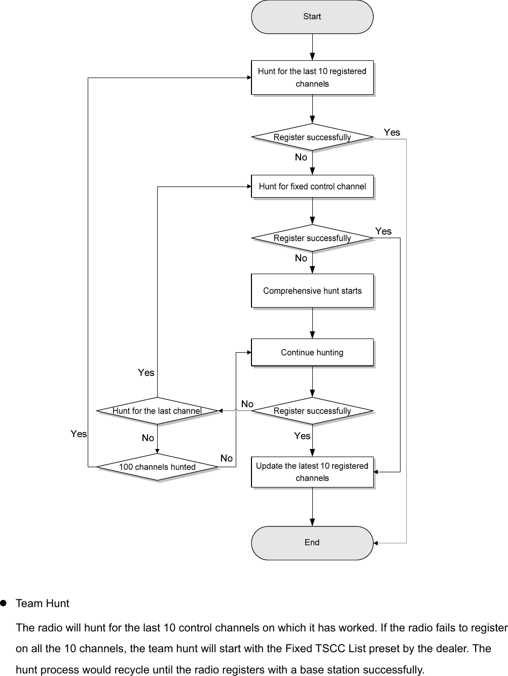
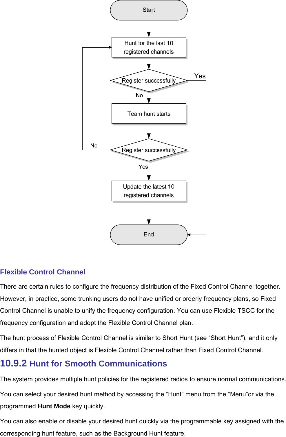
User Manual
Discussion / Help
Navigation