Hytera Communications PD79XISU1 Is Digital Radio User Manual
Hytera Communications Corporation Limited Is Digital Radio Users Manual
Users Manual

File No:HYTERA-I&M-79XIS-001
Rev: V1.0
Preface
Thanks for your favor in our product. To derive optimum performance from the product, please read this
manual and the supplied Safety Information Booklet carefully before use.
This manual is applicable to the following model:
PD79XIS Digital Portable Radio (X may represent 2, 5, 6 or 8).
Date:2015.9.21
Copyright Information
Hytera is the trademark or registered trademark of Hytera Communications Co., Ltd. (the Company) in
PRC and/or other countries or areas. The Company retains the ownership of its trademarks and product
names. All other trademarks and/or product names that may be used in this manual are properties of
their respective owners.
The product describes in this manual may include the Company’s computer programs stored in memory
or other media. Laws in PRC and/or other countries or areas protect the exclusive rights of the Company
with respect to its computer programs. The purchase of this product shall not be deemed to grant, either
directly or by implication, any rights to the purchaser regarding the Company’s computer programs. Any
of the Company’s computer programs may not be copied, modified, distributed, decompiled, or
reverse-engineered in any manner without the prior written consent of the Company.
The AMBE+2TM voice coding technology embodied in this product is protected by intellectual property
rights including patent rights, copyrights and trade secrets of Digital Voice Systems, Inc. This voice
coding technology is licensed solely for use within this product. The user of this technology is explicitly
prohibited from attempting to decompile, reverse engineer, or disassemble the Object Code or in any
other way convert the Object Code into a human readable form.
U.S. Patent No: #6,912,495 B2, #6,199,037 B1, #5,870,405, #5,826,222, #5,754,974, #5,701,390,
#5,715,365, #5,649,050, #5,630,011, #5,581,656, #5,517,511, #5,491,772, #5,247,579, #5,226,084 and
#5,195,166.
Disclaimer
The Company endeavors to achieve the accuracy and completeness of this manual, but no warranty of
accuracy or reliability is given. All the specifications and designs are subject to change without notice
due to continuous technology development. No part of this manual may be copied, modified, translated,
or distributed in any manner without the express written permission of us.
We do not guarantee, for any particular purpose, the accuracy, validity, timeliness, legitimacy or
completeness of the Third Party products and contents involved in this manual.
If you have any suggestions or would like to learn more details, please visit our website at:
http://www.hytera.com.
RF Radiation Information
The radio is not intended for use by general population in an uncontrolled environment. It is only for
occupational use and only applied to work-related conditions.
The radio must be only used by users who are fully aware of the hazards of the exposure and who are
able to exercise control over their RF exposure to qualify for the higher exposure limits.
RF Radiation Profile
Radio Frequency (RF) is a frequency of electromagnetic radiation in the range at which radio signals are
transmitted. RF technology is widely used in communication, medicine, food processing and other fields.
It may generate radiation during use.
RF Radiation Safety
In order to ensure user health, experts from relevant industries including science, engineering, medicine
and health work with international organizations to develop standards for safe exposure to RF radiation.
These standards consist of:
¾ United States Federal Communications Commission, Code of Federal Regulations; 47CFR part 2
sub-part J;
¾ American National Standards Institute (ANSI)/Institute of Electrical and Electronic Engineers (IEEE)
C95. 1-1992;
¾ Institute of Electrical and Electronic Engineers (IEEE) C95. 1 – 1999;
¾ International Commission on Non-Ionizing Radiation Protection (ICNIRP) 1998;
FCC Regulations
Federal Communication Commission (FCC) requires that all radio communication products should meet
the requirements set forth in the above standards before they can be marketed in the U.S, and the
manufacturer shall post a RF label on the product to inform users of operational instructions, so as to
enhance their occupational health against exposure to RF energy.
Operational Instructions and Training Guidelines
To ensure optimal performance and compliance with the occupational/controlled environment RF energy
exposure limits in the above standards and guidelines, users should transmit no more than 50% of the
time and always adhere to the following procedures:
Your radio radiates measurable RF energy only while it is transmitting (during talking), not when
it is receiving (listening) or in standby mode.
EU Regulatory Conformance
As certified by the qualified laboratory, the product is in compliance with the essential requirements and
other relevant provisions of the Directive 1999/5/EC. Please note that the above information is
applicable to EU countries only.
Contents
1. Documentation Conventions ............................................................................................................. 7
1.1 Instructional Icons ........................................................................................................................... 7
1.2 Notational Conventions ................................................................................................................... 7
1.3 Key Operation ................................................................................................................................. 7
2. Intrinsically Safe Radio Information ................................................................................................. 8
2.1 Equipment marking ......................................................................................................................... 8
2.2 No Misoperations ............................................................................................................................ 8
2.3 Safety Instructions .......................................................................................................................... 9
2.4 Specifications .................................................................................................................................. 9
2.5 Compliance Standards .................................................................................................................. 10
3. Items in the Package ........................................................................................................................ 12
4. Product Introduction ........................................................................................................................ 13
4.1 Product Controls ........................................................................................................................... 13
4.2 Programmable Keys ..................................................................................................................... 14
5. Before Use ........................................................................................................................................ 16
5.1 Charge the Battery ........................................................................................................................ 16
5.2 Assembling Accessories ............................................................................................................... 17
5.2.1 Assembling the Antenna ..................................................................................................... 17
5.2.2 Assembling the Battery ....................................................................................................... 17
5.2.3 Assembling the Belt Clip ..................................................................................................... 18
5.2.4 Attaching Audio/Programming Cable .................................................................................. 19
6. Status Indication .............................................................................................................................. 21
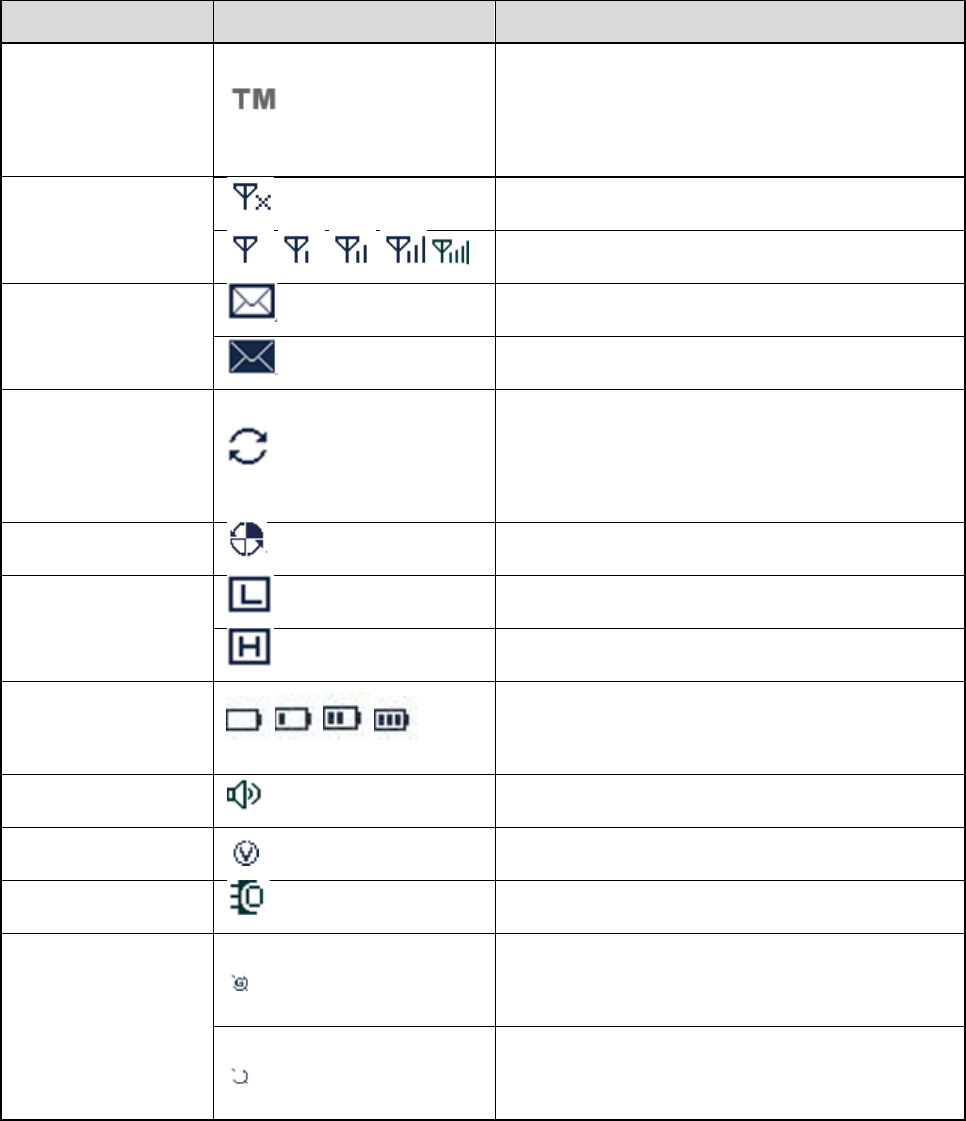
6.1 LCD Icon ....................................................................................................................................... 21
6.2 LED Indicator ................................................................................................................................ 21
7. Menu Navigation ............................................................................................................................... 23
8. Basic Operations .............................................................................................................................. 24
8.1 Powering On/Off ........................................................................................................................... 24
8.2 Registering .................................................................................................................................... 24
8.3 Adjusting the Volume .................................................................................................................... 24
8.4 Locking/Unlocking the Keypad ...................................................................................................... 24
8.5 Selecting a Subgroup .................................................................................................................... 25
8.6 Selecting a Group Contact ............................................................................................................ 25
9. Call ..................................................................................................................................................... 27
9.1 Private Call ................................................................................................................................... 27
9.1.1 Initiating a Call .................................................................................................................... 27
9.1.2 Receiving a Call .................................................................................................................. 28
9.1.3 Voice Communication ......................................................................................................... 28
9.1.4 Conversation Limit .............................................................................................................. 28
9.1.5 Ending a call ....................................................................................................................... 28
9.2 PSTN/PABX Call........................................................................................................................... 29
9.2.1 Initiating a Call .................................................................................................................... 29
9.2.2 Receiving a Call .................................................................................................................. 30
9.2.3 Voice Communication ......................................................................................................... 30
9.2.4 Conversation Limit .............................................................................................................. 30
9.2.5 Ending a call ....................................................................................................................... 30
9.3 Group Call ..................................................................................................................................... 30
9.3.1 Initiating a Call .................................................................................................................... 30
9.4 One Touch Call ............................................................................................................................. 33
9.5 Emergency Call ............................................................................................................................ 33
9.5.1 Initiating a Call .................................................................................................................... 34
9.5.2 Receiving a Call .................................................................................................................. 34
9.5.3 Voice Communication ......................................................................................................... 34
9.5.4 Ending a call ....................................................................................................................... 34
9.6 Queue Call .................................................................................................................................... 34
9.7 Time-out Timer (TOT) ................................................................................................................... 35
10.3.2 CPS-P3 dialing rule .......................................................................................................... 37
10.8 LQO ............................................................................................................................................ 40
10.9 Hunt ............................................................................................................................................ 40
10.9.1 TSCC Hunt ....................................................................................................................... 40
10.9.2 Hunt for Smooth Communications .................................................................................... 43
10.10 Encrypt ...................................................................................................................................... 44
10.11 Authentication ........................................................................................................................... 44
10.12 Covert Mode ............................................................................................................................. 45
10.13 Man Down (optional) ................................................................................................................. 45
10.14 Rent .......................................................................................................................................... 45
10.15 Priority ....................................................................................................................................... 45
10.18 GPS .......................................................................................................................................... 47
11. Troubleshooting ............................................................................................................................. 49
12. Care and Cleaning .......................................................................................................................... 51
1. Documentation Conventions
For your better understanding of this manual, please read the following conventions first.
1.1 Instructional Icons
Icon Description
Note Indicates references that can further describe the related topics.
Caution Indicates situations that could cause data loss or equipment damage.
1.2 Notational Conventions
Convention Description
“ ”
The quotation marks enclose the name of a software interface element.
For example, click “OK”.
Bold The text in boldface denotes the name of a hardware button. For example,
press the PTT key.
->
The symbol directs you to access a multi-level menu. For example, to
select “New” from the “File” menu, we will describe it as follows: File ->
New.
1.3 Key Operation
Operation Definition
Short press To press a key and release it quickly.
Long press To press a key for the preset time (2s by default) and release it.
Hold To press a key and do not release it.
2. Intrinsically Safe Radio Information
2.1 Equipment marking
FM/CAN
z Class I, Zone 0 AEx/Ex ia IIC T4 Ga
z
z Class I,II,III Div1 Group A,B,C,D,E,F,G T120℃
ATEX
z II 1G Ex ia IIC T4
z II 1D Ex ia IIIC T120℃ IP6X
z I M1 Ex ia
IECEx
z Ex ia IIC T4 Ga
z Ex ia IIIC T120 Da IP6X℃
z Ex ia I Ma
2.2 No Misoperations
Stop operating this product and leave the explosive atmosphere immediately when the safety or integrity
of the product is endangered, and deliver it to your local dealer for examination.
These items may endanger the product’s safety or integrity:
z The radio is stored improperly;
z The radio is faulty;
z The radio works with overload;
z The radio’s operational error or threshold value is out of allowed range.
z The radio is damaged during transportation;
z The radio’s housing is obviously damaged or cracked;
z The radio logo or model is hard to be recognized;

2.3 Safety Instructions
Caution
To protect you against any property loss, bodily injury or even death, be sure to observe the following
safety instructions:
z Use only the Ex-battery BL1813-Ex and BL2413-Ex specified by the Company. The use of other
batteries may result in Ex-protection failure.
z Charge the battery in a non-hazardous area only with the designated charger.
z Use the accessories specified by the Company only.
z Do not carry any standby battery into a hazardous area.
z Do not use a damaged antenna. If a damaged antenna comes into contact with your skin, a minor
burn may result.
z Do not expose the radio to direct sunlight for a long time, nor place it close to a heating source.
z Hold the radio upright and keep its microphone 2.5 to 5 centimeters away from your mouth during
use.
z If you wear a radio on your body, ensure its antenna is at least 0 centimeters away from your body
during transmission.
z Please do not use the radio out of the operating temperature range specification of this product.
z Do not disassemble the radio or replace the accessories in a hazardous area.
z Do not remove the battery from the radio in a hazardous area.
z Do not attempt to repair and service the radio, batteries and its accessories. Please contact your
dealer for repair and servicing.
z Do not dissemble or redo the radio. Unauthorized modification of the radio may result in termination
of Ex-protection (intrinsic safety) of the radio.
z Improper usage of the product other than it is intended to be used for will impair safety of the product,
yourself and surrounding environment.
2.4 Specifications
Item Specifications
Rated Operating Voltage DC 7.4V
Max. Operating Voltage DC 8.4V
Max. Operating Current 1.8A

Sensitivity
Weight (with standard antenna
& battery)
About 498g
RF Power Output 1W
Rated Audio Power Output 0.5W
Audio Distortion 3%
Ambient Temperature -30℃–+50℃
Storage Temperature -40℃–+85℃
Charging Temperature 0℃–+40℃
Battery Ex-battery BL1813-Ex (1800mAh) / BL2413-Ex (2400mAh)
Battery Life About 14 hours (5-5-90 duty cycle)
Charging Time About 4 hours
2.5 Compliance Standards
Standard Issue Date
FM
FM Class 3600 2011
FM Class 3610 2010
FM Class 3810 2005
ANSI/IEC-60529(Ed. 4.0) 2004
ANSI/ISA-60079-0(12.00.01) 2009
ANSI/ISA-60079-11(12.02.01) 2012
ANSI/ISA-61010-1(82.02.01) 2004
CAN
CAN/CSA-C22.2 No.0-M91 2006
CAN/CSA-C22.2 No.142-M1987 2009
CAN/CSA-C22.2 No.213-M1987 2008
0.70 μV/(V/m)2 to 0.85 μV/(V/m)2

Standard Issue Date
CAN/CSA-C22.2 No.60079-0 (Ed. 5.0) 2011
CAN/CSA-C22.2 No.60079-11 (Ed. 5.0) 2011
CAN/CSA-C22.2 No.60529 (Ed. 5.0) 2005
CAN/CSA-C22.2 No.61010-1 (Ed. 2.0) 2009
ATEX
EN 60079-0 (Ed. 5.0) 2009
EN 60079-11 (Ed. 6.0) 2012
EN 60529+A1 (Ed. 2.0) 1992
IECEx
IEC-60079-0 (Ed. 5.0) 2007
IEC-60079-11 (Ed. 6.0) 2011
IEC-60529 (Ed. 2.1) 2001
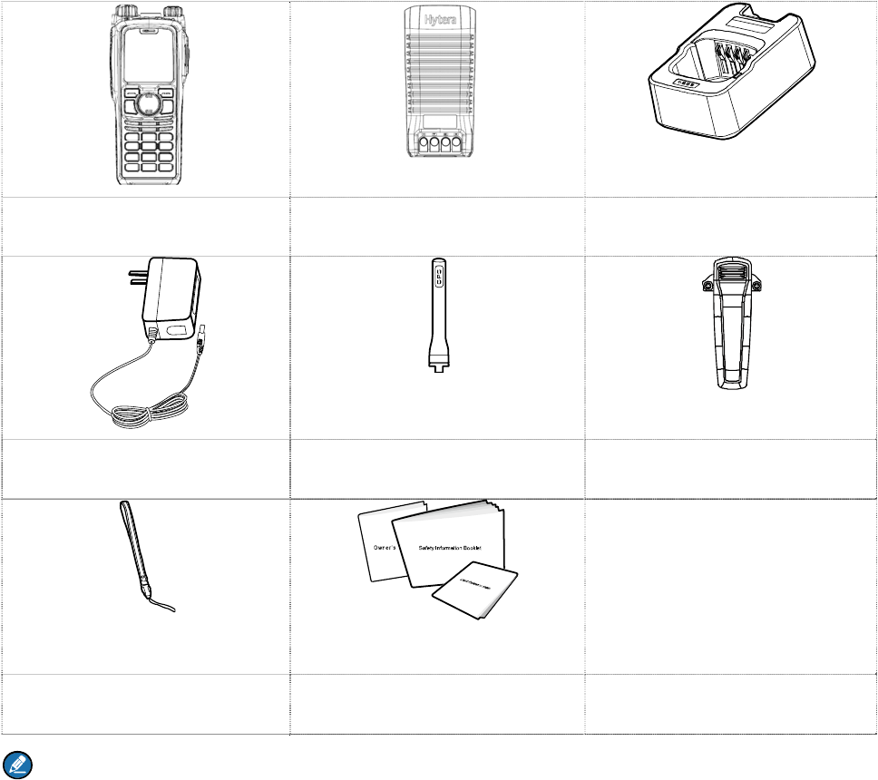
3. Items in the Package
Please unpack carefully and check that all items listed below are received. If any item is missing or
damaged, please contact your dealer.
Portable Radio Battery Charger
Power Adapter Antenna Belt Clip
Strap Documentation Kit
Note
And the frequency band is marked on the label of antenna; if not, refer to the label on the radio for
frequency band information.
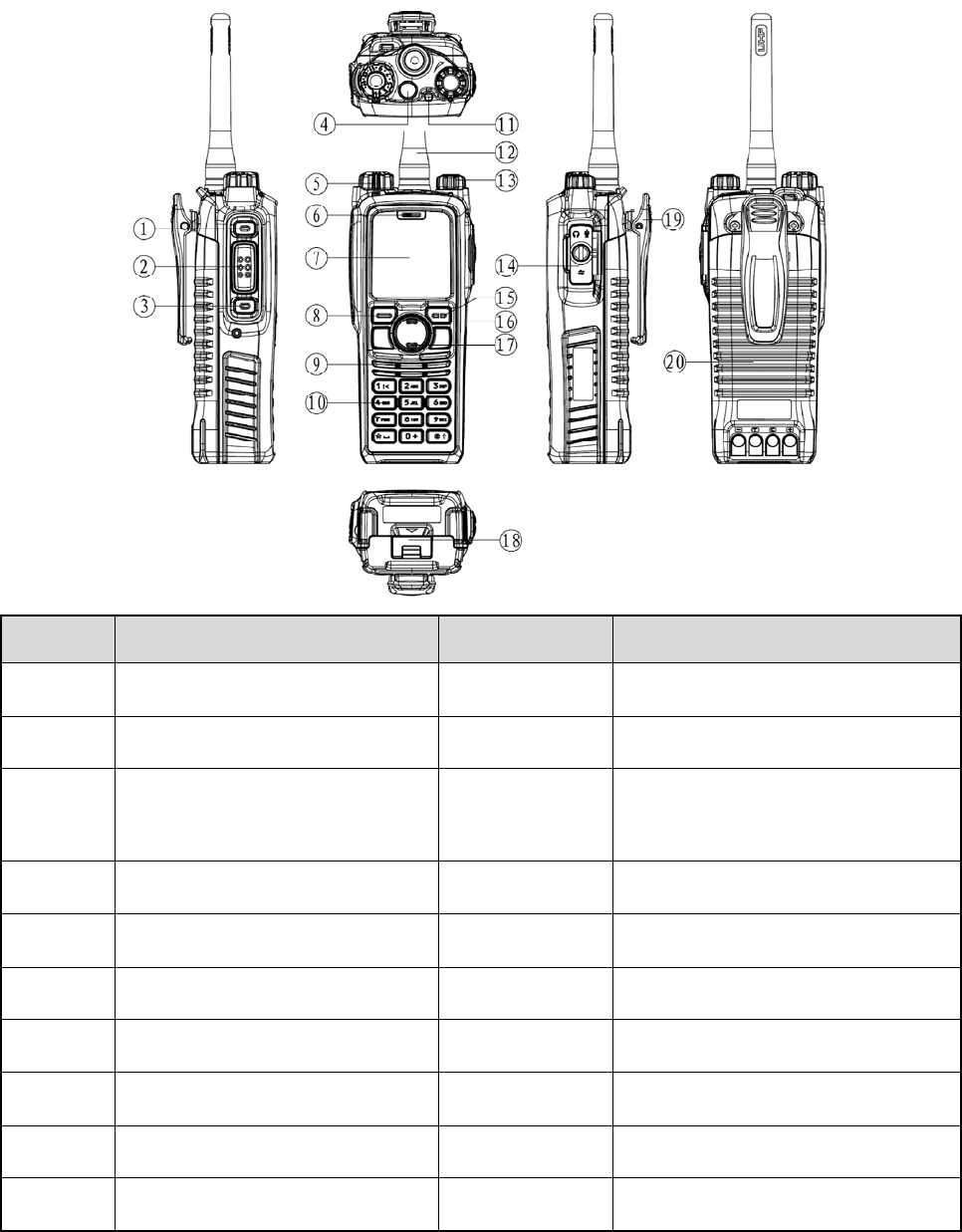
4. Product Introduction
This section introduces the mechanical structure and the programmable key features of this product.
4.1 Product Controls
No. Part Name No. Part Name
○
1 SK1 (Side Key 1) ○
11 LED Indicator
○
2 PTT Key ○
12 Antenna
○
3 SK2 (Side Key 2) ○
13
Power On-Off/Volume Control
Knob
○
4 TK (Top Key) ○
14 Accessory Jack
○
5 Group Call Selector Knob ○
15 Back/Subgroup Key
○
6 Microphone ○
16 Up Key
○
7 LCD Display ○
17 Down Key
○
8 OK/Menu Key ○
18 Battery latch
○
9 Speaker ○
19 Belt clip
○
10 Numeric Keypad ○
20 Battery

4.2 Programmable Keys
For enhanced convenience, you may request your dealer to program the keys SK1, SK2, and TK as
shortcuts to the functions listed below. For detailed introductions of the functions, see the chapter
“Functions and Operations”.
No. Programmable Features Description
1 On-hook To disconnect the call.
2 Keypad Lock To lock or unlock the keypad quickly.
3 Adjust Power Level To adjust Tx power level quickly.
4 Private Contact List To access the menu “Contact List” quickly.
5 Current Subgroup Contact To access the menu “Subgroup” quickly.
6 Call Log To access the menu “Call Logs” quickly.
7 Operation Mode To access the menu “Mode” quickly.
8 Hunt Mode To access the menu “Hunt” quickly.
9 Manual Current Hunt To hunt and make a registration again.
10 Background Hunt To enable or disable the background hunt feature.
11 HomeStation Hunt To enable or disable the home-station hunt feature.
12 Multi-site Handover To enable or disable the multi-site handover feature.
13 Encrypt To enable or disable the encryption feature.
14 LQO To enable or disable LQO.
15 Covert Mode To enable or disable the Covert mode.
16 Emergency On To make an emergency call for help in emergent situations.
17 Emergency Off To end the emergency call.
18 Battery Power Indicator To check the battery power.
19 Man Down To enable or disable the man down function.
20 Message To access the menu “Message” quickly.
21 ReDial Call To call the last person you have contacted.
22 BackDial Call To call the last person who has contacted you.
23 Operation Mode Switch To switch the operation mode of the radio.

No. Programmable Features Description
24 One Touch Call 1-5 To call or to send a message to the preset contact quickly.
25 VOX To enable or disable the VOX feature.
Note
¾ Long and short press of a key can be assigned with different functions by your dealer.
¾ The TK key is programmed as the Emergency On/Off key by default, and is programmable by
your dealer.
5. Before Use
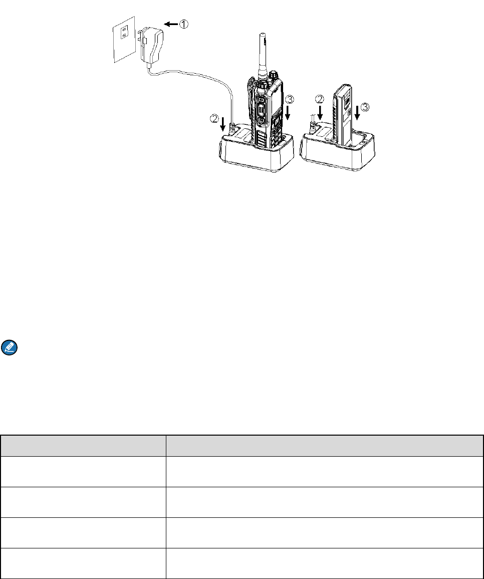
5.1 Charge the Battery
Use only the charger and battery specified by the company. Charger LED can indicate the charging
status, as introduced in the table below. The following figure shows the steps for charging.
Step 1 Connect the power adapter to AC socket. See arrow ①.
Step 2 Plug the power adapter into the rear jack of the charger. See arrow ②.
Step 3 Place the radio with the battery attached, or the battery alone, into the charger. See arrow ③.
During charging, the LED on the charger will indicate the charging status. The charging status begins
when the charger LED glows red. When charging is complete, the charger LED glows green.
See the following table for details.
Note
¾ To achieve optimal battery performance, please charge the battery for 5 hours before initial use.
¾ Be sure to read the Safety Information Booklet, to get necessary battery safety information.
LED Charging Status
The LED flashes red slowly. Standby
The LED glows red. Charging
The LED glows orange. 90% charged
The LED glows green. Fully charged
LED Charging Status
The LED flashes red rapidly. Failure
5.2 Assembling Accessories
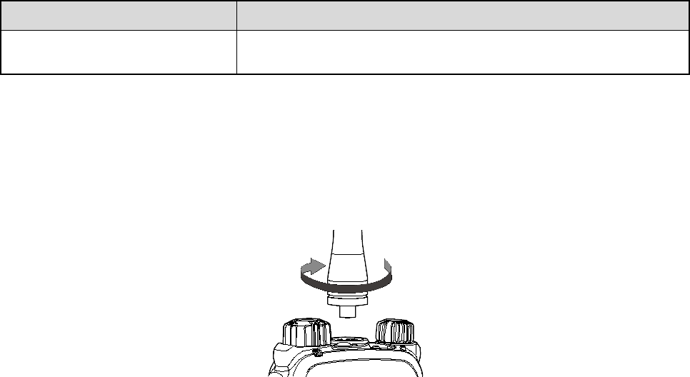
5.2.1 Assembling the Antenna
Turn the antenna clockwise to fasten it.
To remove the antenna, rotate it counter-clockwise.
5.2.2 Assembling the Battery
Step 1 Align the battery slots with the guide rails on the radio, and push the battery ②.
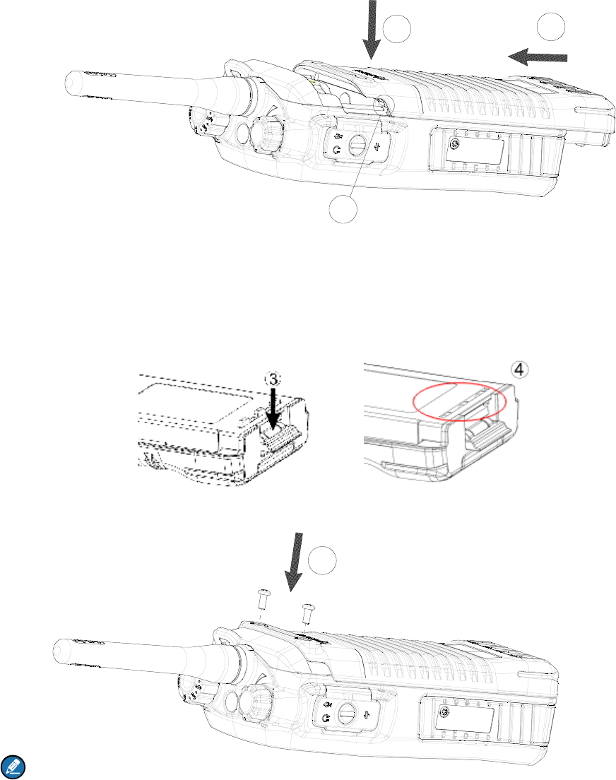
4.3 Attaching the Battery
1. Align the battery slots with the guide rails on the terminal, and push the battery as ○
2 shows.
12
1
2. Open the battery latch and hold it down until the metal lock goes into the battery housing
completely.
3. Push the battery until it is fully fitted into the slot, and then release the battery latch.
4.
Note:
To remove the battery, please power off the terminal first. Then open the battery latch, and slide the
battery out while holding down the battery latch.
5
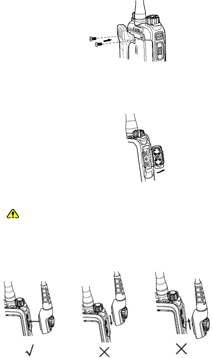
Step 2 Align the screws with the screw holes in the belt clip and on the radio’s back, and then tighten
the screws.
To remove the belt clip, loosen the screws.
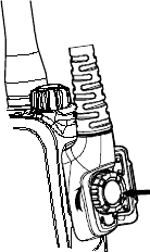
5.2.4 Attaching Audio/Programming Cable
Step 1 Open the accessory jack cover as the arrow shows.
Step 2 Align the plug with the accessory jack.
Caution
¾ When aligning, make sure not to scrape the silica gel surrounding the accessory jack
screw hole, in order to ensure the waterproof performance of the radio.
¾ Be sure to align the screw on the accessory connector to the screw hole in the jack
before fastening the screw.
Step 3 Tighten the screw on the connector.
5.2.3 Assembling the Belt Clip
Step 1 Remove the screws on the back of the radio, as shown in the following figure.
To remove the accessory connector, loosen the screw.
6. St
a
6.1
LC
Icon
Operation
Icon
RSSI Ico
n
Message
Hunt Icon
Roam Ico
TX Powe
r
Battery
Icon
Speaker I
c
VOX Icon
Accessor
y
GPS Icon
6.2
LE
The top L
E
a
tus I
D Icon
Name
Mode
n
Icon
n
r
Icon
Strength
c
on
y
Icon
D Indic
a
E
D will help
y
ndic
a
a
to
r
y
ou easily i
d
a
tion
Icon
d
entify the c
u
T
M
co
m
th
e
No
M
o
Ne
w
In
B
Hu
ba
c
m
u
Th
e
Lo
w
Hi
g
M
o
Th
e
V
O
An
Th
e
re
c
Th
e
da
t
u
rrent radio
M
O Mode:
m
municates
e
trunking s
y
signal.
o
re bars indi
c
w
message
/
B
ox is full.
nt status (
T
c
kground
u
lti-site hand
e
radio is ro
a
w
TX power
g
h TX powe
r
o
re bars indi
c
e
speaker i
s
O
X is active.
accessory
i
e
GPS feat
u
c
eived.
e
GPS fea
t
t
a is receive
status.
Radio S
t
In this
with other
y
stem.
c
ate better
s
/
unread me
s
T
his icon
d
hunt, ho
m
over.)
a
ming.
for the curr
e
r
for the cur
r
c
ate more
b
s
unmated.
i
s connecte
d
u
re is active,
t
ure is acti
v
d.
t
atus
mode, thi
s
radios or s
y
s
ignal stren
g
s
sage.
d
oes not in
m
estation
h
e
nt channel
r
ent channe
b
attery pow
e
d
.
and valid
G
v
e, but no
s
product
y
stems via
g
th.
dicate the
h
unt and
.
l.
e
r.
G
PS data is
valid GPS

LED Indication Radio Status
The LED flashes
green.
Powering on
The LED flashes
green slowly.
Standby
The LED glows
green
Receiving
The LED glows
red
Transmitting
The LED flashes
red.
Making a call (the LED flashes on the calling radio).
The LED flashes
orange rapidly.
Making a FOACSU private call (the LED flashes on the called radio).
The LED flashes
orange slowly.
Hunting
The LED glows
orange.
No voice is being transmitted or received on the channel after a call is
established. Within such period, you can hold the PTT key to talk.
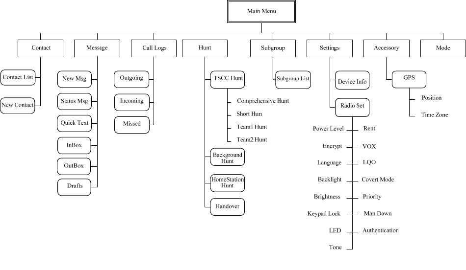
7. Menu Navigation
The following figure outlines your radio’s menu structure. You can personalize menu options displayed in
the radio via your dealer.
To select and confirm the options shown in the menu, press the Menu key to enter the main menu, and
then press the Up/Down key to select your wanted option, finally press the OK key.
This radio supports menu reset function. If you do not operate the menu for a predefined time period, the
radio will automatically return to the home screen. You can define the reset time or cancel the reset
feature via your dealer.

8. Basic Operations
8.1 Powering On/Off
Rotate the Power On-Off/Volume Control knob clockwise/counter-clockwise until a click is heard to
turn the radio on/off.
8.2 Registering
For proper work, the radio will register with a proper base station automatically after powering on.
Hunting the control channel
Before registering, the radio will hunt through the control channels for available base stations.
Step 1 The radio will start hunting automatically after powering on.
There are two hunting plans available. For details, see “Hunt” in “Functions and Operations”
chapter. You need to preset the hunt plan by your dealer. The two hunt plans are:
z Fixed Control Channel
z Flexible Control Channel
Step 2 During the hunt, both the prompt “Registering, Please Wait!” and the icon appear on the LCD,
and the LED flashes orange slowly.
Making a registration
Step 1 When hunting signals of the base station, the radio determines whether the base station allows
it to register.
Step 2 After registering successfully, the radio will display the prompt “Registered Successfully!” on the
LCD. Then it is ready for use. If you want the radio to register with another base station, press
the programmed Manual Current Hunt key to hunt again.
Note: It is highly recommended to put the frequently used frequencies of base stations in the control
channel list via your dealer.
8.3 Adjusting the Volume
After turning on the radio, rotate the Radio On-Off/Volume Control knob clockwise to increase the call
volume and group number notifying volume, or counter-clockwise to decrease them.
8.4 Locking/Unlocking the Keypad
When the keypad is not in use, you can lock it through any of the methods below to prevent accidental
keypad operation.
z Combined Function Key

Use “OK+ ” to lock or unlock the keypad.
z Programmable Keys
Press the programmed Keypad Lock key to lock or unlock the keypad.
z Menu Selection
Go to “Settings -> Radio Set -> Keypad Lock”, and then select “Enable” or “Disable”.
¾ Enable: The keypad will be locked automatically if no operation is made within the preset time
period.
¾ Disable: The keypad will not be locked automatically. However, you can lock or unlock the keypad
via the key combination or Keypad Lock key mentioned above.
Note: When the feature “Keypad Auto Lock” is enabled, the keypad will be locked automatically if no
operation is made within the preset time period. You can use the “Disable" option in the menu “Keypad
Lock” to deactivate the Keypad Auto Lock feature.
8.5 Selecting a Subgroup
You can include your desired group call contacts into a subgroup for efficient management. The radio
supports up to 32 subgroups, each with a maximum of 16 group call contacts.
You may select a subgroup through any of the following methods:
z Menu
Go to the menu “Subgroup -> Members -> Group Call”, Afterwards, select “Set Default” and press the
OK key to switch to that subgroup.
z Shortcuts
In the home screen, directly press the Subgroup key to enter the subgroup menu and select the
subgroup.
Note: This radio supports only one subgroup list which can contain 32 subgroups at most.
8.6 Selecting a Group Contact
Operation
After the radio is powered on and makes a registration successfully, you may select a group call contact
through any of the following methods:
z Knob
Rotate the Group Call Selector knob to select your desired group call contact. An audio alert and
the prompt “No Group Program” will be given in case of no group call contact preset for this knob.
z Menu

Go to the menu “Subgroup -> Members -> Group Call”, and press the Up /Down key to select the
group call contact.
z Shortcuts
You can press the programmed Group Call List key to access the group call list, and select the
group call contact by pressing the Up/Down key.
Group Call Attribute
Group call attribute means the attribute of a group that the group call contacts are in. It is set by the
dealer. This radio supports four group call attributes: Background, Response, Participant and Radio ID.
You can only find and call the contacts of Participant and Response in the subgroup member list, and
receive group calls from the Response, Participant and Background. To receive different attributes of
group calls, you need to have different configurations to the radio as listed below:
Note: When the Radio ID is selected by the Group Call Selector knob, the radio can receive any
group call made by the available group call contacts.
Group Call
Attribute Settings
Response
If the group call contact is available in the subgroup member list, the radio can
receive the group calls made to this group without any operation by the Group
Call Selector knob.
Participant
Only when the Participant group call contact or the Radio ID is selected by the
Group Call Selector knob, can the radio receive the group calls made to this
group.
Background
This group call contact is unavailable. Only when this group call contact is preset
by the dealer, can the radio receive the group calls to this group.

9. C
a
To ensure
o
centimeter
s
Note:
O
Selector k
n
9.1
Pri
Private call
z FOAC
S
z OACS
U
automa
9.1.1
I
n
When the
r
given until
t
methods.
Contact
L
Step 1 E
n
C
a
Step 2 U
s
Step 3 Pr
ReDial o
r
Step 1 In
Step 2 U
s
Step 3 Pr
Manual
D
Step 1 In
“F
u
Step 2 Pr
Missed
C
Press the
P
press the
a
ll
o
ptimal vol
u
s
away fro
m
O
nce the ra
d
n
ob, the ra
d
vate C
a
supports t
w
S
U: During c
U
: During ca
tically.
n
itiating
a
r
adio trans
m
t
he called p
a
L
ist or Ca
l
n
ter the Con
a
lls (path: “
M
s
e the Up/D
o
ess the
r
BackDia
l
the home s
c
s
e the Up/D
o
ess the
D
ial
the home s
c
u
nctions an
d
ess the
C
all Scree
n
P
TT key in t
h
key
o
u
me of the r
e
m
your mout
h
d
io hasn’t m
a
d
io cannot
m
a
ll
w
o call type
s
all setup, th
ll setup, the
a
Call
m
its a privat
e
a
rty answer
l
l Logs
tact List (p
a
M
enu -> Cal
l
o
wn key to
or the P
T
l
Call Log
c
reen, pres
s
o
wn key to
or the P
T
c
reen, inpu
t
d
Operation
key, PT
T
n
h
e “Missed
C
o
r the PTT k
e
e
ceiving ra
d
h
.
a
de a regis
t
m
ake a call.
s
, FOACSU
e calling ra
d
calling radi
o
e
call, the ic
o
s this call.
Y
a
th: “Menu -
>
l
Logs”).
select the p
T
T key to m
a
s
the
select the p
T
T key to m
a
t
a private c
a
s” chapter f
o
T
key or
C
all” scree
n
e
y to call b
a
d
io, keep th
e
t
ration or no
and OACS
U
d
io rings. T
h
o
does not
r
o
n wi
Y
ou may tra
n
>
Contact -
>
rivate call c
o
a
ke a call.
or
rivate call c
o
a
ke a call.
a
ll number
u
o
r the rang
e
key to
m
n
to directly
c
a
ck when vi
e
e
microphon
e
group call
c
U
, configure
h
e called pa
r
r
ing. The cal
ll appear o
n
n
smit a priv
a
>
Contact Li
s
o
ntact you
w
key to acce
s
o
ntact you
w
u
sing the ke
y
e
of private
c
m
ake a call
.
c
all back th
e
e
wing that c
a
e
approxim
a
c
ontact is pr
d by the tru
n
r
ty answers
led party a
n
n
the LCD.
T
a
te call thro
u
s
t”) or Outg
o
w
ant to call.
s
s the appr
o
w
ant to call.
y
pad. See “
M
c
all number.
.
e
last misse
d
a
ll number.
a
tely 2.5 to
5
eset for the
n
king syste
m
the call ma
n
n
swers the
c
T
he ring indi
c
u
gh any of t
o
ing/Incomi
n
o
priate call l
o
M
anual Dial
d
private cal
5
Group Cal
l
m
.
n
ually.
c
all
c
ation is
he followin
g
n
g/Missed
o
g.
” in
l contact, o
r
l
g
r
9.1.2
R
e
FOACSU
When a pri
v
on the LC
D
call, and th
e
the radio
w
OACSU
P
The call is
e
successfull
9.1.3
Vo
After a priv
if the PTT
k
transmissi
o
9.1.4
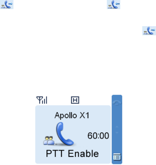
C
o
When a pri
v
in a real-ti
m
z At the
c
The cal
period i
s
time.
z At the
c
The cal
9.1.5
E
n
The voice
c
z Neither
z The cal
z Either t
h
e
ceivin
g
Private
C
v
ate call ar
r
D
as well. Y
o
e
radio will
d
w
ill display t
h
P
rivate C
a
e
stablished
y.
o
ice Co
m
ate call is e
s
k
ey is free
w
o
n and the i
c
o
nversa
t
v
ate call is
e
m
e way. Se
e
c
alling party
ling party w
i
s
program
m
c
alled party
led party wi
l
n
ding a
c
c
ommunica
t
of the parti
e
l duration e
x
h
e calling p
a
g
a Call
C
all
r
ives, both ri
o
u may pres
d
isplay the i
c
h
e icon
a
ll
automatica
l
m
munic
a
s
tablished,
e
w
ith the LCD
c
on
u
t
ion Lim
e
stablished,
e
the followi
n
i
ll display th
e
m
ed by your
l
l display th
e
c
all
t
ion will be t
e
e
s holds do
w
x
ceeds the
a
ar
ty or the c
a
ng and vibr
a
s the
c
on . An
to remind
y
l
ly. The ico
n
a
tion
e
ither the c
a
displaying
“
u
pon receip
t
it
both the c
a
n
g figure.
e
total allo
w
dealer. The
e
actual co
m
e
rminated
w
w
n the PTT
a
llowed tim
e
a
lled party
e
a
tion indicat
or PTT ke
y
alert tone
w
y
ou.
n
will a
p
a
lling party
o
“
PTT Enabl
e
t
respectivel
a
lling party
a
w
ed time for
call will be
e
m
munication
w
hen one of
key to talk
w
e
preset by
t
e
nds the in-
p
ion will be g
y
within the
w
ill be given
p
pear on th
e
o
r the called
e
d!”. The ra
d
y.
a
nd the call
e
a call in a
w
e
nded whe
n
time.
the followin
g
w
ithin the pr
e
t
he dealer.
p
rogress ca
l
iven, with t
h
preset time
as well. If y
o
e
LCD when
party can t
r
d
io will displ
a
e
d party will
d
w
ay of count
i
n
its duratio
n
g
situations
e
set time.
l
l.
h
e icon
period to a
n
o
u don’t an
s
this call is
e
r
ansmit a v
o
a
y the icon
d
isplay the
c
i
ng down. T
h
n
exceeds t
h
occurs:
displaye
d
n
swer the
wer this cal
l
e
stablished
o
ice call onl
y
durin
g
c
all duratio
n
h
is time
h
e preset
d
l
,
y
g
n

z Signal
o
z Either t
h
z A pre-e
m
9.2
PS
The radio
c
PABX call,
9.2.1
I
n
When the
r
the called
p
Contact
L
Step 1 E
n
C
a
Step 2 U
s
Step 3 Pr
ReDial o
r
Step 1 In
Step 2 U
s
Step 3 Pr
Manual
D
Step 1 In
sc
z
z
Step 2 Pr
Missed
C
Hold the P
T
press the
o
f base stati
h
e calling p
a
m
ptive call
o
TN/PA
B
c
an make a
n
the followin
n
itiating
a
r
adio trans
m
p
arty answe
L
ist or Ca
l
n
ter the Con
a
lls (path: “
M
s
e the Up/D
o
ess the
r
BackDia
l
the home s
c
s
e the Up/D
o
ess the
D
ial
the home s
c
hemes. (Fo
r
CPS-P/C
P
1343-E Di
Note
To make
a
¾
CPS-
P
¾
1343-
E
ess the
C
all Scree
n
T
T key in th
e
or th
e
on is missi
n
a
rty or the c
a
o
r emergen
c
B
X Call
n
d receive a
g operation
s
a
Call
m
its a PSTN
rs this call.
Y
l
l Logs
tact List (p
a
M
enu -> Cal
l
o
wn key to
or PTT
k
l
Call Log
c
reen, pres
s
o
wn key to
or PTT
k
c
reen, inpu
t
r
details, se
e
P
S-P3 Diali
n
aling: *01*
+
a
PABX call,
P
/CPS-P3 D
i
E
Dialing: *0
key, PT
T
n
e
“Missed
C
e
PTT key t
o
n
g.
a
lled party
s
c
y call occu
p
PSTN/PA
B
s
are based
call, the ico
Y
ou may tr
a
a
th: “Menu -
>
l
Logs”).
select the
P
k
ey to make
s
the
select the
P
k
ey to make
t
a number
u
e
“Manual
D
n
g: 01 + PS
T
+
PSTN nu
m
enter the n
u
i
aling: 02 +
P
2* + PABX
n
T
key or
C
all” screen
t
o
call back
w
s
elects an e
m
p
ies the cur
r
B
X call. Sinc
on the PS
T
n w
i
a
nsmit a PS
T
>
Contact -
>
P
STN conta
c
a PSTN ca
l
or
P
STN conta
c
a PSTN ca
l
u
sing the ke
y
D
ial” in “Fun
c
T
N number.
m
ber.
u
mber acco
P
ABX num
b
n
umber.
key to
t
t
o directly c
a
w
hen viewin
g
m
pty group
r
ent channe
e PSTN cal
l
T
N call.
i
ll appear. T
T
N call thro
u
>
Contact Li
s
c
t you want
t
l.
key to acce
s
c
t you want
t
l.
y
pad accor
d
c
tions and
O
rding to eit
h
b
er.
t
ransmit a
P
a
ll back the
g
that call n
u
by the Gro
u
l.
l
has the sa
m
he ring indi
c
u
gh any of t
s
t”) or Outg
o
t
o call.
s
s the appr
o
t
o call.
d
ing to eith
e
O
perations”
c
h
er of the fol
P
STN call.
last missed
u
mber.
u
p Call Sel
e
m
e calling
p
c
ation will b
e
he followin
g
o
ing/Incomi
n
o
priate call l
o
e
r of the foll
o
c
hapter).
lowing sch
e
PSTN call
c
e
cto
r
knob.
p
rocess with
e
given until
g
methods.
n
g/Missed
o
g.
o
wing
e
mes.
c
ontact, or

9.2.2
R
e
When a P
S
on the LC
D
call.
When the
c
don’t answ
e
9.2.3
Vo
When a P
S
radio cann
o
9.2.4
C
o
When a P
S
of counting
The call wi
l
9.2.5
E
n
The voice
c
z The cal
z Either t
h
z A pre-e
m
z The ra
d
z Either t
h
z Either
o
z Signal
o
9.3
Gr
o
Group call
party and t
h
while the c
a
The radio
c
As these t
w
difference
s
9.3.1
I
n
When the
r
any of the
f
e
ceivin
g
S
TN call arri
v
D
as well. Y
o
c
all is establ
e
r this call,
t
o
ice Co
m
S
TN call is
e
o
t receive t
h
o
nversa
t
S
TN call is
e
down. The
l
l be ended
w
n
ding a
c
c
ommunica
t
l duration is
h
e calling p
a
m
ptive call
o
d
io switches
h
e calling p
a
o
f the partie
s
o
f base stati
o
up Ca
l
includes ge
h
e called p
a
a
lled party i
s
c
annot mak
e
w
o types of
g
s
in the follo
w
n
itiating
a
r
adio trans
m
f
ollowing m
e
g
a Call
v
es, both ri
n
o
u may pres
ished, the r
a
t
he radio wi
l
m
munic
a
e
stablished,
h
e voice of t
h
t
ion Lim
e
stablished,
called part
y
w
hen its du
r
c
all
t
ion will be t
e
over the all
a
rty or the c
a
o
r emergen
c
its operatio
n
a
rty or the c
a
s
turns off t
h
on is missi
n
l
l
neral group
a
rty can spe
a
s
able to lis
t
e
a broadca
s
g
roup calls
h
w
ing sectio
n
a
Call
m
its a group
c
e
thods.
n
g and vibra
s the
a
dio will dis
p
l
l display th
e
a
tion
you can tal
k
h
e PSTN u
s
it
the calling
p
y
will displa
y
r
ation exce
e
e
rminated
w
owed time
p
a
lled party
e
c
y call occu
p
n
mode via
a
lled party
s
h
e radio or l
o
n
g.
call and br
o
a
k. Howeve
t
en to it onl
y
s
t group cal
l
h
ave the sa
m
n
.
c
all, the ico
n
tion indicati
o
or PTT ke
y
p
lay the ico
n
e
icon
k
by holding
s
er.
p
arty will dis
y
the actual
c
e
ds the pres
w
hen one of
p
reset by th
e
e
nds the in-
p
p
ies the cur
r
the menu.
s
elects an e
m
o
gs out of t
h
o
adcast gro
u
r, in a broa
d
y
.
l
unless the
m
e operatio
n
will
o
n will be gi
v
y
within the
n
. Ring
to remind y
o
the PTT ke
y
play the cal
l
c
ommunica
t
et time.
the followin
g
e
dealer.
p
rogress ca
l
r
ent channe
m
pty group
h
e system.
u
p call. In a
d
cast call, o
n
dealer auth
ns in gener
a
appear. Yo
u
v
en, with th
e
preset time
alert will be
o
u.
y
. When tra
l
time prese
t
t
ion time.
g
situations
l
l.
l.
by the Gro
u
general gro
n
ly the calli
n
orizes it.
a
l, we will o
n
u
may trans
e
icon
period to a
n
given as w
e
nsmitting th
e
t
by the de
a
occurs:
u
p Call Sel
e
up call, bot
h
n
g party can
n
ly detail th
e
mit a group
displaye
d
n
swer the
e
ll. If you
e
voice, the
a
ler in a way
e
cto
r
knob.
h
the calling
speak,
e
ir
call throug
h
d
h
Transmit
In the hom
e
Call Selec
t
Group C
o
Step 1 In
th
e
Step 2 G
o
Step 3 U
s
Step 4 Pr
Y
o
ReDial o
r
Step 1 In
Step 2 U
s
Step 3 Pr
Y
o
or
To
p
Manual
D
Step 1 In
“F
u
z
z
Step 2 Pr
9.3.2
R
e
You can re
be given a
s
ting a cal
l
e
screen, p
r
t
o
r
knob tu
r
o
ntact
the home s
c
e
Subgrou
p
o
to “Subgr
o
s
e the Up/D
o
ess
o
u can also
s
key or
t
Note
To make
a
press the
O
r
BackDia
l
the home s
c
s
e the Up/D
o
ess the
o
u can also
s
the PTT ke
y
Note
To
make a b
r
ress the O
K
D
ial
the home s
c
u
nctions an
d
General g
Broadcas
t
number.
ess the
e
ceivin
g
ceive a gro
u
s
well.
l
to the pr
e
r
essing the
P
r
ns to.
c
reen, pres
s
p
key to ent
e
o
up -> Mem
b
o
wn key to
or PTT key
s
elect the “
G
t
he PTT ke
y
a
broadcast
O
K key,
l
Call Log
c
reen, pres
s
o
wn key to
or PTT
k
s
elect the “
G
y
to make t
h
r
oadcast gr
o
K
key,
c
reen, inpu
t
d
Operation
roup call: g
r
t
group call:
key, PT
T
g
a Call
u
p call with
o
e
set cont
a
P
TT key will
s
the Menu
k
e
r the “Sub
g
b
ers”.
select the g
to make a
g
G
eneral Gro
y
to make th
group call,
s
key or
t
s
the
select the g
k
ey to mak
e
G
eneral Gro
h
e call.
o
up call, sel
e
key or the
t
a group ca
l
s” chapter f
o
r
oup call nu
m
In both CP
S
T
key or
o
ut any ope
r
a
ct
transmit a
g
k
ey and the
n
g
roup” men
u
roup call co
g
roup call.
up Call” as
t
e call.
s
elect the “
B
t
he PTT ke
y
or
roup call co
e
a general
g
up Call” as
t
e
ct the “Bro
a
PTT key.
l
l number u
s
o
r the rang
e
m
be
r
S
-P and CP
S
key
r
ation and t
h
g
roup call t
o
n
select the
u
.
ntact you w
a
t
he “Call Ty
p
B
roadcast G
y
.
key to acc
e
ntact you w
a
g
roup call.
t
he “Call Ty
p
a
dcast Gro
u
s
ing the key
e
of group c
a
S
-P3 dialin
g
to make a
c
h
e radio will
o
the group
c
“Subgroup”
a
nt to call.
p
e”, and th
e
roup Call” a
e
ss the app
r
a
nt to call.
p
e”, and pr
e
u
p Call” as t
h
pad. See “
M
a
ll number.
g
schemes, i
c
all.
display the
c
all contact
menu, or d
i
e
n press the
s the “Call
T
r
opriate call
e
ss the OK
k
h
e “Call Ty
p
M
anual Dial”
nput *11*+
g
icon . Ri
the Group
i
rectly pres
s
OK key,
T
ype”, and
log.
k
ey,
p
e”, and
in
g
roup call
ng alert will
s
9.3.3 Late Entry
After a group call is established, other group members are allowed to join it without any operation.
The late entry feature is used in the following situations:
z The called party is not in the group operation range until the group call is established.
z The called party is not powered on until the group call is established.
z During the initiation of the group call, the called party is in another call (a private call or a group call).
When the call is over, the group call is still on.
z During the initiation of the group call, the called party is within poor signal coverage or is
encountering with the radio interference, and the signal gets better during the group call.
z A new member joins when the group call is established.
9.3.4 Voice Communication
z General Group Call: After the call is established, either the calling party or the called party can
transmit a voice call only if the PTT key is free with “PTT Enabled!” displayed on the LCD. The radio
will display the icon upon transmitting and the icon upon receipt respectively.
z Broadcast Group Call: After the call is established, only the calling party can talk by holding the PTT
key. When transmitting the voice, the calling party will display the icon on the LCD. As for the
called party, it can only receive voice.
9.3.5 Conversation Limit
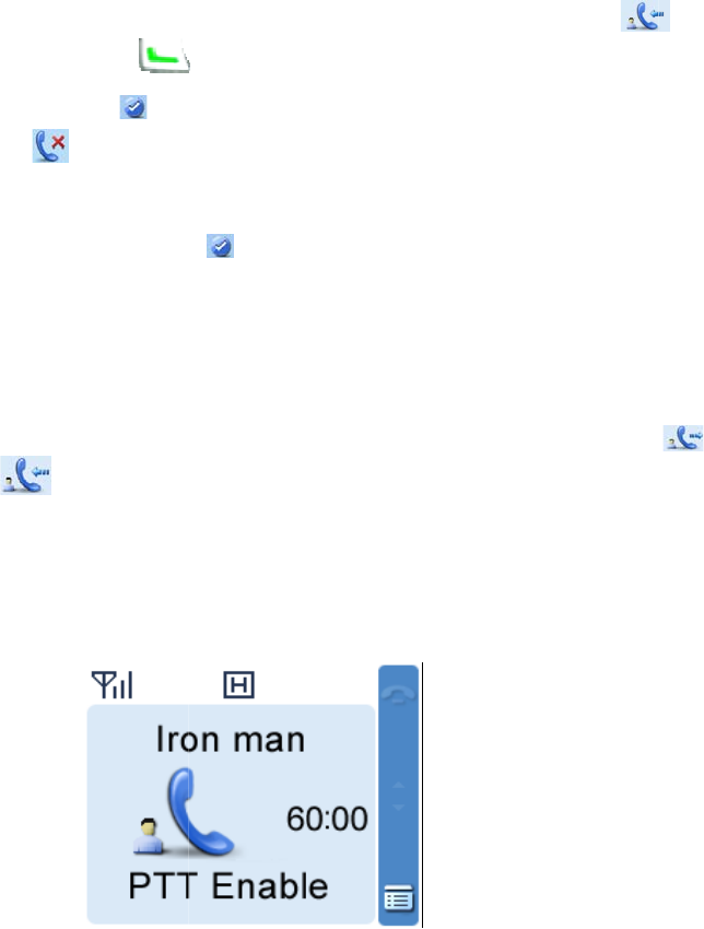
When a general group call is established, both the calling party and the called party will display the call
duration in a real-time way. See the following figure.
z At the calling party
The calling party will display the total conversation time for the call in a way of counting down the total
allowed time. This time period is programmed by your dealer. The call will be ended when its duration
exceeds the preset time.
z At the called party

The called party will display the actual conversation time. The timer will start counting once the called
party joins the group call. If the called party takes the initiative to exit from this call and then rejoins it
later, recount will be initiated.
9.3.6 Ending a call
General Group Call
The voice communication will be terminated when one of the following situations occurs:
z Neither of the parties holds the PTT key to talk within the preset time.
z The call duration exceeds the allowed time preset by the dealer.
z The calling party ends the in-progress call.
z Signal of base station is missing.
z A pre-emptive call or emergency call occupies the current channel.
Note:
If you hold the PTT key while some one is speaking, your radio will keep beeping, alerting you to
transmission prohibition. To stop beeping, please release the PTT key. When the PTT is free, you
can hold the PTT key to transmit.
Broadcast Group Call
The call will be terminated when one of the following situations occurs:
z The call duration exceeds the allowed time preset by the dealer.
z The calling party ends the in-progress call.
z Signal of base station is missing.
z A pre-emptive call or emergency call occupies the current channel.
9.4 One Touch Call
You dealer can set 5 One Touch Call shortcuts at most for you. This feature is used for calling the
contact or sending the message quickly. The contact, call type and the message contents are all preset
by the dealer.
Operation: To initiate a call or send a message, press the programmed One Touch Call key.
9.5 Emergency Call
In case of an emergency, you can use the feature to ask for help from your companion or control center.
Emergency call is the highest-priority call which can disconnect any ongoing normal calls.
Only when the radio is authorized to emergency call, can it transmit such calls.
9.5.1
I
n
When the
r
emergenc
y
Shortcut
s
Press the
p
by the deal
Man Do
w
Man Down
Manual
D
Step 1 In
ke
Step 2 Pr
9.5.2
R
e
When an e
9.5.3
Vo
After an e
m
PTT key is
transmissi
o
9.5.4
E
n
The emerg
z The cal
z When t
h
Emerg
e
z Signal
o
z When t
h
Emerg
e
Note:
B
¾
Call
i
¾
Call
e
9.6
Q
u
When the
c
of channel
s
n
itiating
a
r
adio trans
m
y
call throug
h
s
p
rogramme
d
er.
w
n Trigge
r
alarm will t
r
D
ial
the home s
c
ypad.
ess the
e
ceivin
g
mergency
c
o
ice Co
m
m
ergency c
a
free with “
P
o
n and the i
c
n
ding a
c
ency call wi
l duration e
x
h
e emergen
e
ncy mode.
o
f base stati
h
e emergen
e
ncy mode.
B
oth calling
p
i
ng Party: p
r
e
d Party: pr
e
u
eue Ca
c
hannels ar
e
s
. When the
a
Call
m
its an emer
h
any of the
d
Emergen
c
r
r
igger an e
m
c
reen, inpu
t
key, PT
T
g
a Call
c
all arrives,
y
m
munic
a
a
ll is establi
s
P
TT Enable
d
c
on
u
c
all
ll be termin
a
x
ceeds the
a
cy call is m
a
on is missi
n
cy call is m
a
p
arty and t
h
r
esses the
E
e
sses the T
ll
e
busy, the
c
radio make
s
gency call,
t
following
m
c
y On key t
o
m
ergency c
a
t
“*9* + the
n
T
key or
y
ou can ans
a
tion
s
hed, either
d
!” displaye
d
u
pon receipt
a
ted when
o
a
llowed tim
e
a
de to the g
n
g.
a
de to the p
h
e called pa
r
E
mergency
K key withi
n
c
alls will qu
e
s
a call with
t
he icon
m
ethods.
o
transmit a
n
a
ll to the call
n
umber you
key to
t
wer it witho
u
the calling
p
d
on the LC
D
respectivel
y
o
ne of the fo
e
preset by
t
roup conta
c
rivate call c
o
r
ty adopt dif
f
Off key.
n
1s after pr
e
e
ue accordi
n
a low priori
t
will appe
n
emergenc
y
ed party se
t
want to call
t
ransmit an
u
t any oper
a
p
arty or the
c
D
. The radio
y
.
llowing situ
a
t
he dealer.
c
t, the callin
g
o
ntact, both
f
erent meth
o
e
ssing the
B
n
g to their p
r
t
y, it will dis
p
ar. You ma
y
y
call to the
t
by the dea
l
(e.g.: *9*8
0
emergency
a
tion.
c
alled party
will display
a
tions occu
r
g
party end
s
parties end
o
d to exit th
e
B
ack key.
r
iorities for t
p
lay the pro
m
y
transmit a
n
called part
y
l
er.
0
020200)” u
s
call.
can speak
o
the icon
r
s:
s
the call or
e
the call or
e
e
Emergen
c
he system'
s
m
pt “Queue
n
y
configured
s
ing the
o
nly if the
during
e
xits the
e
xit the
c
y mode.
s
distributio
n
Call” on th
e
n
e
LCD.
9.7 Time-out Timer (TOT)
The purpose of TOT is to prevent any user from occupying a channel for an extended period. If the
preset time expires, the radio will automatically terminate the transmission and keep beeping. To stop
beeping, please release the PTT key. You must wait for a certain time period (preset by your dealer) to
initiate another transmission.

10. F
10.1
H
The featur
e
In the editi
n
menu imm
e
immediatel
10.2
M
You can m
a
10.2.1
C
You can s
a
“Contact -
>
V
iewing
a
You can vi
e
Editing a
You can e
d
Deleting
You can d
e
10.2.2
N
You can a
d
alias can c
o
chapter.
Note:
¾
You
¾
You
10.3
M
You can in
p
In the hom
e
10.3.1
C
Number
A contact
n
uncti
o
ome S
c
e
allows yo
u
n
g screen,
p
e
diately; in
o
y.
M
anagin
a
nage your
C
ontact
a
ve up to 20
0
>
Contact Li
s
a
Contact
e
w the alias
Contact
d
it the numb
e
a Contac
t
e
lete a cont
a
N
ew Co
n
d
d a new co
n
o
ntain 16 c
h
can press t
h
can save t
h
M
anual
D
p
ut the priv
a
e
screen, in
C
PS-P d
n
umber is c
o
o
ns
a
c
reen
u
to quickly
r
p
ress the
o
ther scree
n
g the
C
private call
List
0
entries of
s
t” or press
t
and numb
e
e
r and alias
t
a
ct from the
n
tact
n
tact to the
c
h
aracters at
h
e
h
e numbers
D
ial
a
te or group
put your de
s
ialing ru
o
mposed of
a
nd O
p
r
eturn to the
key, a
n
n
s, press thi
s
C
ontact
s
contacts vi
a
private call
c
t
he shortcu
t
e
r of the con
t
of the cont
a
contact list.
c
ontact list.
T
most. For t
h
key to s
w
from the C
a
contact ID
s
ired ID, an
d
le
3 parts: NP
p
erat
i
previous m
n
d the radio
s
key and t
h
s
a
the menu
“
c
ontact info
t
key for Pri
v
t
acts.
a
cts.
Please not
e
T
he numbe
r
h
e number
r
w
itch the inp
u
a
ll Logs, Re
D
manually u
s
d
press the
(3 digits) +
F
i
ons
enu or the
h
exits the s
c
h
e radio ret
u
“
Contact” in
rmation in t
h
v
ate Call Co
e
that the lis
r
and alias o
r
ange, plea
s
u
t method
w
D
ial List an
d
s
ing the key
p
, PT
T
F
N (2 digits
)
h
ome scree
n
c
reen and re
u
rns to the h
the radio.
h
e list. To a
c
ntact.
t must cont
a
f each cont
a
s
e refer to “
M
w
hen editing
d
BackDial
L
p
ad to mak
e
T
, or
)
+ UN/GN (
n
.
turns to the
ome scree
n
c
cess the li
s
a
in one con
t
a
ct must be
M
anual Dial
”
the alias.
L
ist into the
c
e
a call .
key to
m
3 digits), to
t
previous
n
s
t, select
t
act at least
.
unique. Th
e
”
in this
c
ontact list.
m
ake a call.
t
ally 8 digits
.
.
e
.
z NP (the number prefix) range: 328–899
z FN (the fleet number) range: 20–65 (for private call), 20–99 (for group call)
z UN (the unit number, for private call) range: 200–899; GN (the group number, for group call) range:
900–999
Dialing rules
z In-fleet call: to directly dial UN/GN (3 digits) only.
z Inter-fleet call: to dial the FN (2 digits) + UN/GN (3 digits).
z Inter-prefix call: to dial the NP (3 digits) + FN (2 digits) + UN/GN (3 digits).
10.3.2 CPS-P3 dialing rule
Number
A contact number is composed of 3 parts: NP (3 digits) + FN (2 digits) + UN/GN (3 digits), totally 8 digits.
z NP (the number prefix) range: 328 – 899
z FN (the fleet number) range: 20 – 89 (for both private call and fleet group call); 90, 97, 98, 99 (for
hierarchical group call).
z UN (the unit number)/GN (the group number) range
¾ For private call: When FN ranges from 20 to 41, UN will range from 200 to 899; when FN ranges
from 42 to 89, UN will range from 200 to 549.
¾ For fleet group call, GN range is 900 – 999; for hierarchical group call, GN range is 000 – 999.
Dialing rules
z In-fleet call: to directly dial UN/GN (3 digits) only.
z Inter-fleet call: to dial the FN (2 digits) + UN/GN (3 digits).
z Inter-prefix call: to dial the NP (3 digits) + FN (2 digits) + UN/GN (3 digits).
10.3.3 1343-E dialing rule
This feature allows you to customize the dialing rules. You can request your dealer to customize the
dialing rule according to your actual needs. Please note that the user should follow the same scheme in
the same trunking system and each contact number is unique.
To learn more details regarding this dialing rule, please contact your local dealer.
10.4 Message
Sending a message
Step 1 Go to “Menu -> Message -> New Message” to enter the relevant interface .
Step 2 Type the text and press the OK key.
Step 3 Select the contact or input the contact number manually.
Step 4 Press the OK key to send the message. When the message is sent successfully, the radio will
display “Send Success!” on the LCD.
You can send the Quick Text or Status Message or forward the message saved in the InBox, OutBox or
Drafts. See the detailed introductions of the submenus of Message respectively.
New Message
You can create a new text message (23 characters at most) and save it to Drafts, or send it to a private
call contact or a group call contact.
Quick Text
Under this option there are some text messages (10 entries at most) preset by your dealer. You can
choose to edit and send any entry.
Status Message
Status Message contains the status code rather than the text, to ensure privacy of your communication. It
is preset by your dealer via the programming software. You can send but not edit the message.
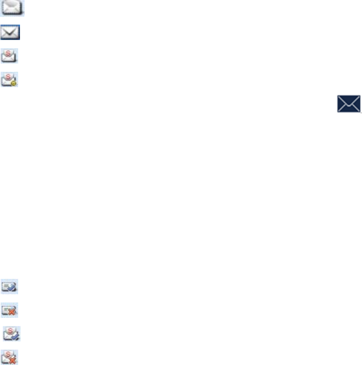
InBox
The radio saves the received messages into the InBox and gives every message a corresponding icon
to show whether it is read.
z : Read message
z : Unread message
z : Read status message
z : Unread status message
The InBox can save up to 50 received messages. When it is full, the icon will appear, and the
earliest message will be overwritten by the latest one automatically.
z For each message, you can choose to perform any of these operations: Reply, Forward (Status
Message excluded), View Details and Delete.
z To delete all messages in the InBox, select “Message -> Inbox -> Delete All”.
OutBox
The OutBox can save up to 50 sent messages. The following icons will appear to indicate whether the
message is sent successfully.
z : Message is sent successfully.
z : The message is not sent successfully. In this case, you can resend it.
z : Status Message is sent successfully.
z : Status Message is not sent successfully. In this case, you can resend it.
When the OutBox is full, no icon will appear on LCD to alert you. In addition, the earliest message will

be overwri
t
z For ea
c
Messa
g
z To dele
t
Drafts
The Drafts
overwritten
For each
m
z After th
e
Outbox
.
z To dele
t
10.5
C
The radio
s
At most 10
Outgoing/I
n
The Misse
d
Operation
:
menu dire
c
After acce
s
to initiate a
Outgoing/I
n
10.6
M
This featur
e
product wil
proper vol
u
10.7
V
VOX indic
a
instead of
h
volume to
t
When VO
X
To enabl
e
Press the
p
t
ten by the l
a
c
h message
,
g
e excluded
)
t
e all mess
a
can save u
p
by the late
s
m
essage, yo
e
message
.
t
e all mess
a
C
all Log
s
s
aves only t
h
call entries
n
coming/Mi
s
d
list includ
e
:
You can p
r
c
tly via the
p
s
sing a list
a
call, add th
n
coming/Mi
s
M
IC AG
C
e
can be en
l control the
u
me for the
r
O
X
a
tes that the
h
olding the
P
t
rigger the t
r
X
is enabled
,
e
or disa
b
p
rogramme
d
a
test one a
u
,
you can c
h
)
, View Det
a
a
ges in the
O
p
to 20 draf
t
s
t one auto
m
u can choo
s
in the Draft
s
a
ges in the
D
s
h
e entries o
f
can be sav
e
s
sed list is f
u
e
s the miss
e
r
ess the Me
p
rogrammed
a
nd selectin
g
e entry to
C
s
sed list at
a
C
abled by yo
audio gain
r
eceiving ra
d
voice trans
P
TT key. W
r
ansmission
,
the icon
b
le the VO
X
d
VOX key.
u
tomatically.
h
oose to per
f
a
ils and Del
e
O
utBox, sel
e
t
messages.
m
atically.
s
e to perfor
m
s
is sent, it
w
D
rafts, sele
c
f
private cal
l
e
d in the O
u
u
ll, the earli
e
e
d FOACSU
nu key to e
n
Call Log k
e
g
an entry,
y
C
ontact List
o
a
time, sele
c
ur dealer vi
a
to a proper
d
io.
mission ca
n
hen the mic
, the trans
m
will app
e
X
feature
f
orm any of
e
te.
e
ct “Messag
When the
D
m
any of the
w
ill be remo
v
c
t “Message
l
s, PSTN c
a
u
tgoing/Inco
e
st entry wil
calls and
O
n
ter “Menu
-
e
y.
y
ou can perf
o
o
r delete it.
T
c
t “Call Log
s
a
the progr
a
range durin
n
be initiate
d
rophone de
t
m
ission is st
a
e
ar on the L
these oper
a
e -> Outbo
x
D
rafts is full
,
se operatio
n
v
ed from th
e
-> Drafts -
>
a
lls and PA
B
ming/Misse
d
l be overwri
t
O
ACSU call
s
-
> Call Log
s
o
rm any of
t
T
o delete al
s
-> Outgoin
g
a
mming soft
w
g
transmiss
d
by speaki
n
t
ects that y
o
a
rted autom
a
CD.
a
tions: Res
e
x
-> Delete
A
,
the earlies
t
n
s: Send, S
a
e
Drafts and
>
Delete All”.
B
X calls but
n
d
list respe
c
t
ten by late
s
s
.
s
” menu, or
e
t
hese opera
t
l entries in t
g
/Incoming/
w
are. Whe
n
ion, providi
n
n
g into the
m
o
ur voice re
a
a
tically.
e
nd, Forwar
d
A
ll”.
t
message
w
a
ve and De
l
be saved t
o
n
ot group c
a
c
tively. Whe
n
s
t one auto
m
e
nter the “C
t
ions: hold t
he
Missed ->
D
n
it is enable
n
g improved
m
icrophone
o
a
ches the r
e
d
(Status
w
ill be
l
ete.
o
the
a
lls.
n
the
m
atically.
all Logs”
he PTT key
D
elete All”.
d, the
voice with
o
f radio
e
quired

Select “Menu -> Settings -> Radio Set -> VOX” menu.
Adjust VOX Gain Level
You can adjust the sensitivity of microphone transmission via the “Menu -> Settings -> Radio Set -> VOX
-> Gain Level” menu. The bigger the gain level, the higher the gain and the lower the sensitivity. Thus,
the high volume is required to trigger the transmission.
z Internal VOX Gain Level: the sensitivity of internal microphone transmission.
z External VOX Gain Level: the sensitivity of external microphone transmission.
Caution: Please adjust the VOX Gain Level properly on your actual requirements.
10.8 LQO
This feature enables the radio to adjust the received voice volume automatically in standby mode to fit
different using environments, as well as making the heard voice clear.
Operation: You can enable or disable the LQO feature by pressing the programmed LQO key or via the
“Settings -> Radio Set -> LQO” menu.
10.9 Hunt
There are two types of hunt in different stages: the TSCC hunt during registration and the hunt for
smooth communications after registration.
10.9.1 TSCC Hunt
In trunking system, the radio is required to register with a base station prior to normal operation. Before
registering, the radio will hunt through the control channels for available base stations. During hunting,
the LCD displays “Registering, Please Wait!” and the icon , and the LED flashes orange slowly.
There are two hunt plans: Fixed Control Channel and Flexible Control Channel. You can set the
appropriate plan via your dealer.
Fixed Control Channel
There are certain rules to define the frequency distribution of the Fixed Control Channel together. If the
trunking user frequency has such characteristic, you can configure the frequency for the radios together
via the Fixed TSCC, and adopt the Fixed Control Channel plan.
If you adopt this plan, you can select the hunt mode by going to “Hunt -> TSCC Hunt” menu or pressing
the programmed Hunt Mode key to access “Hunt” menu quickly.
See the hunt modes as follows:
z Short Hunt
In this mode, the radio will hunt for the last 10 control channels on which it registered successfully. If
the radio fails to register on all the 10 channels, it will orderly hunt the channels in the Fixed TSCC
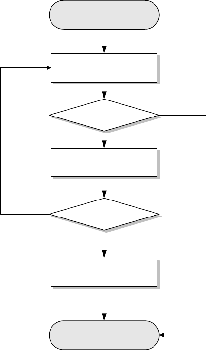
List preset by the dealer. The hunt process would recycle until the radio registers with a base station
successfully.
Start
Register successfully
Hunt for the last 10
registered channels
Update the latest 10
registered channels
Hunt for fixed control
channel
Register successfully
End
No
Yes
Yes
No
z Comprehensive Hunt
If Short Hunt brings no successful registration, Comprehensive Hunt will go from the channel defined
at Lowest of Comprehensive Hunt. During the hunt, after every 100 channels are hunted, the
previously mentioned 10 channels would be hunted again. If no successful registration is achieved
after comprehensive hunt, the hunt will go on with the Fixed TSCC List. The hunt process would
recycle until the radio registers with a base station successfully.
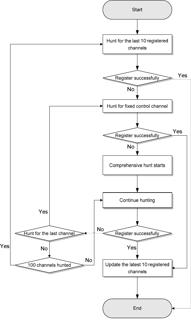
z Team Hunt
The radio will hunt for the last 10 control channels on which it has worked. If the radio fails to register
on all the 10 channels, the team hunt will start with the Fixed TSCC List preset by the dealer. The
hunt process would recycle until the radio registers with a base station successfully.
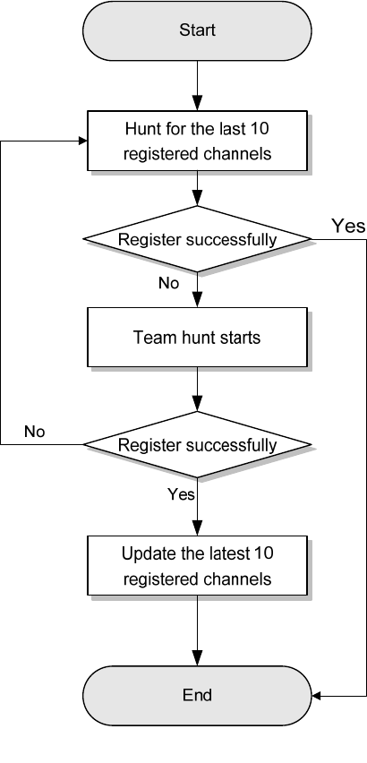
Flexible Control Channel
There are certain rules to configure the frequency distribution of the Fixed Control Channel together.
However, in practice, some trunking users do not have unified or orderly frequency plans, so Fixed
Control Channel is unable to unify the frequency configuration. You can use Flexible TSCC for the
frequency configuration and adopt the Flexible Control Channel plan.
The hunt process of Flexible Control Channel is similar to Short Hunt (see “Short Hunt”), and it only
differs in that the hunted object is Flexible Control Channel rather than Fixed Control Channel.
10.9.2 Hunt for Smooth Communications
The system provides multiple hunt policies for the registered radios to ensure normal communications.
You can select your desired hunt method by accessing the “Hunt” menu from the “Menu”or via the
programmed Hunt Mode key quickly.
You can also enable or disable your desired hunt quickly via the programmable key assigned with the
corresponding hunt feature, such as the Background Hunt feature.
Background Hunt
The idle radio will check the signal strength of the base station with which it registers. If the signal
strength of the base station is below the value defined at Threshold Level, the radio will automatically
hunt for another one with better signal and registers with it. Thus, the radio can always work with a base
station with strong signal.
HomeStation Hunt
The feature offers the radio the priority to register with a frequently used base station. This can balance
the base station load well, especially in the area covered by multiple base stations, increasing system
response speed and improving communication quality.
Each base station has a limited load. When the number of the radios registered with a base station
reaches the upper limit, the system response will be delayed, resulting in intermittent communications.
However, a radio works in a fixed area most of the time. Even though it works on the channel of another
base station in the area covered by multiple base stations, it will jump to work on its home channel once
the signal strength of the channel matches the defined value. The communications will not be affected at
all during base station switch.
Handover
The change in radio position may cause the signal strength received from base station to fluctuate, and
the communication quality is affected accordingly. In case of weak signal strength, this feature enables
the radio to work with another base station having better signals automatically, assuring quality
communications.
10.10 Encrypt
Encrypt indicates the voices transmitted are encrypted between radios. For example, Radio A transmits
the encrypted voice to Radio B, and Radio B should enable Encrypt feature to receive the voice.
Operation: You can enable/disable the Encrypt feature via the programmed Encrypt key or by entering
the menu “Menu -> Settings -> Radio Set -> Encrypt”.
10.11 Authentication
Authentication is used to ensure the validity of the user accounts in the network. It operates in a way that
the radio and the base station authenticate the validity of each other. Currently, the authentication is only
needed during registration. Only when both the radio and the base station pass the authentication can
the registration be made.
Operation: You can enable/disable the feature via the “Menu -> Settings -> Radio Set -> Authentication”
menu.
10.12 Covert Mode
When this feature is enabled, the radio will close any visible indications on it, such as the LED, Vibration,
etc, which are set by your dealer. This feature is mainly used in special missions.
Operation: To enable or disable the Covert mode, you can press the programmed Covert Mode key, or
enter the menu “Menu -> Settings -> Radio Set -> Covert Mode”.
10.13 Man Down (optional)
Your radio will sound a pre-alert tone if it is positioned aslant for a preset time period, and will enter the
Emergency mode if you do not place it vertically within such time period. To exit the Emergency mode,
please place it upright.
You can enable or disable the Man Down feature by pressing the programmed Man Down key or via the
menu “Menu -> Settings -> Radio Set -> Man Down”.
The radio gives a high-pitched tone when the Man Down feature is enabled and a low-pitched tone when
the feature is disabled.
10.14 Rent
You can rent the radio from your dealer. . When the rental period expires, you are not allowed to use this
radio.
You can check the remaining rental time via the menu “Menu -> Settings -> Radio Set -> Rent -> Rent
Query”.
If the Rent Pre-Alert feature is enabled, the radio will give a tone periodically to remind you of the
remaining time on your rental.
10.15 Priority
This feature indicates the priority of the normal voice services. When there is no free service channel in
the system, the system will respond to the higher-priority voice service first.
The normal voice services include all calls, such as private call, general group call, broadcast group call,
PSTN call, PABX call, etc, except emergent call.
You can set the priority of your normal voice services via the menu “Menu -> Settings -> Radio Set ->
Priority”.
z The priority follows this principle: Low < Medium < High. When the channels are occupied, the calls
will queue according to their priorities for the system's distribution of channels. When the queue is full,
the higher-priority calls can jump the queue, and, accordingly, the lower-priority calls will be extruded
out (the system will prompt that it is busy). In addition, the emergency calls or preemption calls can
forcibly disconnect the on-going lower-priority calls to release the channels for themselves.

z Preemption: This is the highest priority. When the system is busy, such calls do not need to queue.
They can disconnect other on-going calls with lower priority to release the channels for themselves.
Note: The “Preemption” option will not be available in your radio unless your dealer enables it.
10.16 Radio Set
You can optimize your radio performance via the following configuration according to actual needs and
your preferences.
Enter “Menu -> Settings -> Radio Set” menu to set the items as introduced below:
Power Level
This menu is to set the Tx power level to High or Low. High power can extend the coverage, enabling
you to communicate with farther radios.
Alternatively, you can toggle the power level by pressing the programmed Adjust Power Level key in
the home screen.
On the LCD, High power is indicated by and Low power is indicated by .
Language
This option allows you to set the language in which all interface information is displayed. Currently, this
radio only supports English and Simplified Chinese.
Backlight
This menu allows you to set the backlight. Activating the backlight can illuminate the LCD and the
keypad, so as to facilitate your operation under dim light conditions. The menu has the following options:
z Off: The backlight will always remain off.
z On: The backlight is on all the time.
z Timed: If no operation or signal transmission/receipt occurs within the time preset by the dealer, the
backlight will be turned off automatically.
Brightness
This option allows you to set the display brightness. You can raise or lower it using the Up/Down key.
Keypad Lock
This option allows you to set whether to enable this function. When "Enable" is selected, you can use the
Up/Down key to set the time range after which the keypad will be locked. Available range: 5 – 60
seconds.
LED Indicator
This option allows you to set whether to enable LED indicator. Generally, the LED indicator can indicate
Tx/Rx, Hunt status, Incoming Call, etc. The indications of the LED are set by the dealer.

Tone
You can select the tones on actual requirements.
Tone Description
Radio Silent This feature disables all the tones.
Talk Permit
The tone given upon successful signal transmission to prompt the user to
talk.
Private Call The tone given when the radio receives a private call successfully.
TxtMsg The tone given when the radio receives a message.
Keypad The tone given when you are operating the keypad.
Low Battery
The tone given when the radio is in low battery status. Then you will need
to replace the battery.
Call End Tone The tone given upon a call ending.
Group Call Tone The tone given upon the receipt of a group call.
Incoming Call Tone The tone given upon the receipt of a FOACSU call.
PTT Enable The tone given when the PTT is enabled to transmit the voice.
Hunt Tone The tone given when the radio starts the control channel hunt.
Group Notify
The group number played when you are selecting the group call contacts
by the Group Call Selector knob.
Call Queued
The tone given when the radio is in the call queue, with the prompt “Queue
Call” displayed on the LCD.
10.17 Mode
This feature allows you to select the work mode for the radio. Be prudent about this operation, as the
change of mode will cause your radio to reboot.
Operation: Press the programmed Operation Mode Switch key to switch the mode directly.
You can also press the programmed Operation Mode key to enter “Mode” menu or go to “Menu ->
Mode” for switching.
10.18 GPS
When GPS feature is enabled, you can check the position information of the radio and choose the time
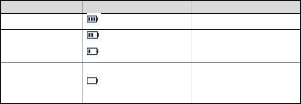
zone for it. Go to “Menu -> Accessories -> GPS”.
10.19 Device Info
With this option, you can view basic information of your radio, including radio ID, serial number, model
name, frequency range, firmware version, radio data version, boot loader version, etc.
Go to “Menu -> Settings -> Device Info”.
10.20 Battery Power Indicator
This feature allows you to know the current battery power.
Hold down the programmed Battery Power Indicator key, and the radio will give a specific indication to
represent the current battery power. Release this key to exit.
Indication Battery Power Icon Battery Power
The LED glows green. High
The LED glows orange. Medium
The LED glows red. Low
The LED glows red and
the low battery tone
sounds.
Insufficient

11. Troubleshooting
Phenomena Analysis Solution
Power-on failure
The battery may be
improperly installed.
Remove the battery and attach it again.
The battery may run out. Recharge or replace the battery.
The battery may suffer from
poor contact caused by
dirtied or damaged battery
contacts.
Clean the battery contacts. If the problem can
not be solved, contact your dealer or authorized
service center for inspection and repair.
The radio cannot
register
successfully.
The radio may not detect
signals from the base station.
Make sure you are within the coverage of the
base station.
The radio maybe not be
authorized.
Contact the base station manager to check
whether your radio is authorized in the network
management system.
The radio registers
repeatedly.
The signal is discontinuous.
Make sure you are within the coverage of the
base station.
The radio cannot
establish a call.
The signal is poor.
Make sure you are within the coverage of the
base station.
No voice is heard
after a call is
established.
Your ID may be repeated.
Contact the base station manager to check
whether your ID is repeated in the network
management system.
The called party
disconnects
repeatedly during
communication.
The signal is discontinuous.
Make sure you are within the coverage of the
base station.
During receiving,
the voice is weak,
discontinuous or
totally inactive.
Low battery Recharge or replace the battery.
The volume may be set to a
low level.
Increase the volume by rotating the Volume
Control knob clockwise, or ask your dealer to
disable the Digital Mic AGC feature.
The antenna may get loose
or improperly installed.
Power off the radio, re-install the antenna and
power on the radio again.

Phenomena Analysis Solution
The speaker may be blocked
or damaged.
Clean surface of the speaker. If the problem can
not be solved, contact your dealer or our
authorized service center for inspection and
repair.
You can not
communicate with
other members.
The signal is poor.
Make sure you are within the communication
range.
The voice is
unclear.
The signal is poor.
Make sure you are within the communication
range.
The noise is too
loud.
The signal is poor.
Make sure you are within the communication
range.
You may be at an
unfavorable position. For
example, your
communication may be
blocked by high buildings or
frustrated in the underground
areas.
Move to an open and flat area, and restart the
radio.
You may suffer from external
disturbance (such as
electromagnetic
interference).
Stay away from equipment that may cause
interference.
You can not use
the keys.
The keypad may fail to
function temporarily.
Restart the radio.
The LCD does not
display any
information.
The LCD may fail to function
temporarily.
Restart the radio.
If the above solutions can not fix the problems for you, or you may have some other queries, please
contact us or your local dealer for more technical support.

12. Care and Cleaning
To guarantee optimal performance as well as a long service life of the product, please follow the tips
below.
Product Care
z Do not pierce or scrape the product.
z Keep the product far away from substances that can corrode the circuit.
z Do not hold the product by its antenna or earpiece cable directly.
z Attach the accessory jack cover when the product is not in use.
Product Cleaning
Caution: Power off and remove the battery before cleaning. Clean up the dust and fine particles
on the product surface and charging piece with a clean and dry lint-free cloth or a brush regularly.
z Use neutral cleanser and a non-woven fabric to clean the keys, control knobs and front case after
long-time use. Do not use chemical preparations such as stain removers, alcohol, sprays or oil
preparations, so as to avoid surface case damage.
z Make sure the product is completely dry before use.
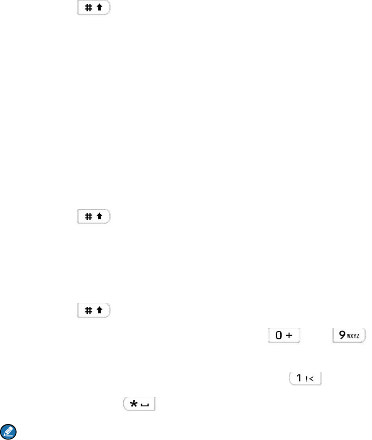
13. Appendix
13.1 Input Method
You can enter aliases, numbers or messages using the keypad. The radio supports these input methods:
Chinese Pinyin (simplified), English and Number.
Chinese Pinyin (Simplified)
Step 1 Press to switch to Chinese Pinyin mode.
Step 2 Enter the pinyin through alphanumeric keys; then a list of possible combinations and
corresponding characters will appear.
Step 3 Use the Up/Down key to choose the right pinyin.
Step 4 Press the OK key to highlight the characters, and choose the right character using the
Up/Down key.
Step 5 Press the OK key to enter the selected character.
You can repeat the above steps to continue.
English
Step 1 Press to switch to uppercase English or lowercase English mode.
Step 2 Press the key which bear your desired letter repeatedly until the letter appears.
You can repeat the above steps to continue.
Number
Step 1 Press to switch to Number mode.
Step 2 Enter the numbers through alphanumeric keys to .
Special Character
To enter common punctuations and special characters, press .
To input a space, press .
Note: You can use the Up/Down key to move the cursor leftward/rightward in the entered text.
and guidelines:
complies with the following RF energy exposure standards
FCC Statement
Operation is subject to the following two conditions: 1. This device may not cause harmful
interference, and 2. This device must accept any interference received, including
interference that may cause undesired operation.
Note:” Changes or modifications to this unit not expressly approved by the party
responsible for compliance could void the user’s authority to operate the equipment.”
Compliance with RF Exposure Standards
Hytera’s Is Digital Radio
• United States Federal Communications Commission, Code of Federal Regulations; 47
CFR § 1.1307, 1.1310 and 2.1093
• American National Standards Institute (ANSI) / Institute of Electrical and Electronic
Engineers (IEEE) C95. 1:2005; Canada RSS102 Issue 5 March 2015.
• Institute of Electrical and Electronic Engineers (IEEE) C95.1:2005 Edition
RF Exposure Compliance and Control Guidelines and
Operating Instructions
To control your exposure and ensure compliance with the occupational/controlled
environment exposure limits always adhere to the following procedures.
Guidelines:
• Do not remove the RF Exposure Label from the device.
• User awareness instructions should accompany device when transferred to other users.
• Do not use this device if the operational requirements described herein are not met.
Operating Instructions:
• Transmit no more than the rated duty factor of 50% of the time. To transmit (talk), push
the Push-To-Talk (PTT) button. To receive calls, release the PTT button. Transmitting
50 % of the time, or less, is important because this radio generates measurable RF
energy exposure only when transmitting (in terms of measuring for standards
compliance).
• Hold the radio in a vertical position in front of face with the microphone (and the other
parts of the radio, including the antenna) at least one inch (2.5 cm) away from the nose.
Keeping the radio at the proper distance is important because RF exposures decrease
with distance from the antenna. Antenna should be kept away from eyes.
• When worn on the body, always place the radio in a Hytera’s approved clip, holder,
holster, case, or body harness for this product. Using approved body-worn accessories is
important because the use of Hytera’s or other manufacturer’s non-approved accessories
may result in exposure levels, which exceed the FCC’s occupational/controlled
environment RF exposure limits.
• Use only manufacturer’s name approved supplied or replacement antennas, batteries,
and accessories. Use of non-manufacturer-name approved antennas, batteries, and
accessories may exceed the FCC RF exposure guidelines.
IC statement
The device has been tested and compliance with SAR limits, users can obtain Canadian
information on RF exposure and compliance
Après examen de ce matériel aux conformité aux limites DAS et/ou aux limites d’intensité
de champ RF, les utilisateurs peuvent sur l’exposition aux radiofréquences et la
conformité and compliance d’acquérir les informations correspondantes
This device complies with Industry Canada licence-exempt RSS standard(s). Operation is subject to the
following two conditions:
(1) this device may not cause interference, and
(2) this device must accept any interference, including interference that may cause undesired operation
of the device.
Le présent appareil est conforme aux CNR d'Industrie Canada applicables aux
appareils radio exempts de licence. L'exploitation est autorisée aux deux conditions
suivantes : (1) l'appareil ne
doit pas produire de brouillage, et (2) l'utilisateur de l'appareil doit accepter tout
brouillage radioélectrique subi, même si le brouillage est susceptible d'en
compromettre le fonctionnement