Hyundai IBT PT42DA000 PDP TV User Manual 1 7 Appen eng
Hyundai IBT Corp. PDP TV 1 7 Appen eng
Contents
- 1. Users Manual 1a
- 2. Users Manual 1b
- 3. Users Manual 2
- 4. Users Manual 3
Users Manual 2
13
General Information
ENGLISH
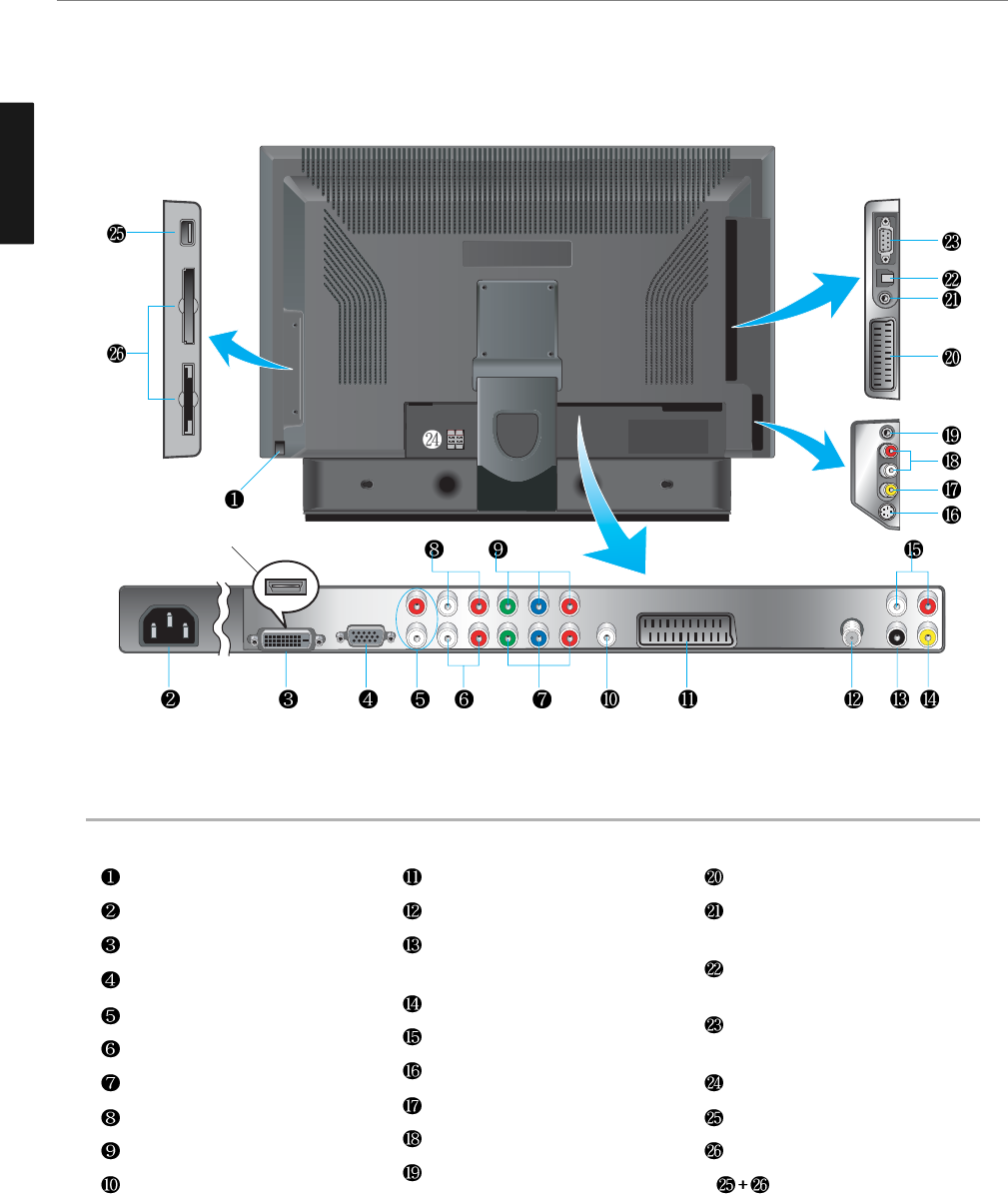
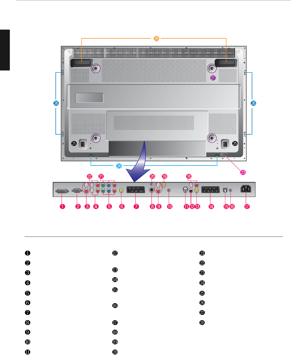
Rear View
Power switch
Power (AC) input terminal
DVI Video / HDMI input terminal
D-SUB input terminal
DVI/D-SUB Audio input terminal
Component 2 Audio input terminal
Component 2 Video input terminal
Component 1 Audio input terminal
Component 1 Video input terminal
CVBS output terminal
Full Scart input terminal
Antenna input terminal
Digital Audio output terminal for
coaxial cable
Subwoofer output terminal
Extend Audio ontput terminal
S-Video input terminal
Video(CVBS) input terminal
Audio(CVBS) input terminal
Headphone output terminal
Half Scart input terminal
Extend an RS-232 input for ATV
communication.
SPDIF Optical audio output
terminal
Extend an RS-232 input for DTV
communication.
Speaker terminal
USB Input Terminal
Memory Card Slot
* For Q320 Model only
* This product image may be a bit different from the actual product.
HDMI Option
14
General Information
ENGLISH
Parts Names and Functions - 40” LCD TV
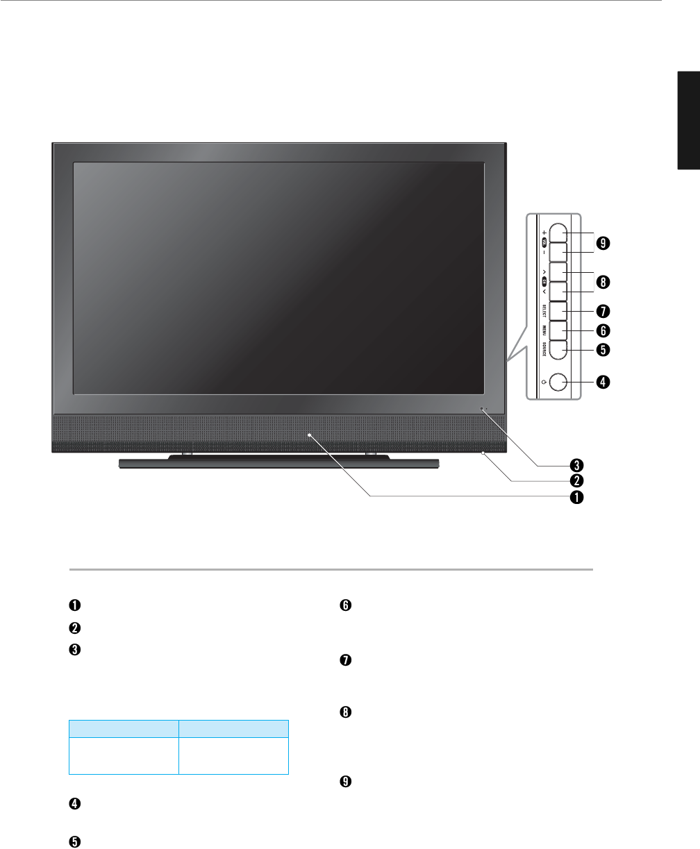
Front View
Speakers
Power Switch
Remote sensor and power LED.
- Point the remote control toward LED.
- It displays standby or operation status.
Standby/On button
Use this button to turn on or off the TV.
Source button
Use this button to switch among inputs
connected to the TV.
Menu button
Use this button to display or exit from the menu
mode.
Select button
Use this button to select each item from the
menu mode.
Channel buttons
Use these buttons to change channels. These
buttons also serve as the cursors of Down and
Up buttons in Menu mode.
Volume buttons
Use these buttons to adjust sound levels.
These buttons also serve as the cursors of
Select/Adjust in Menu mode.
* This product image may be a bit different from the actual product.
- Power Indicator Status -
Indicator
Red
Green
Status
Standby
Power on
ENGLISH
15
General Information
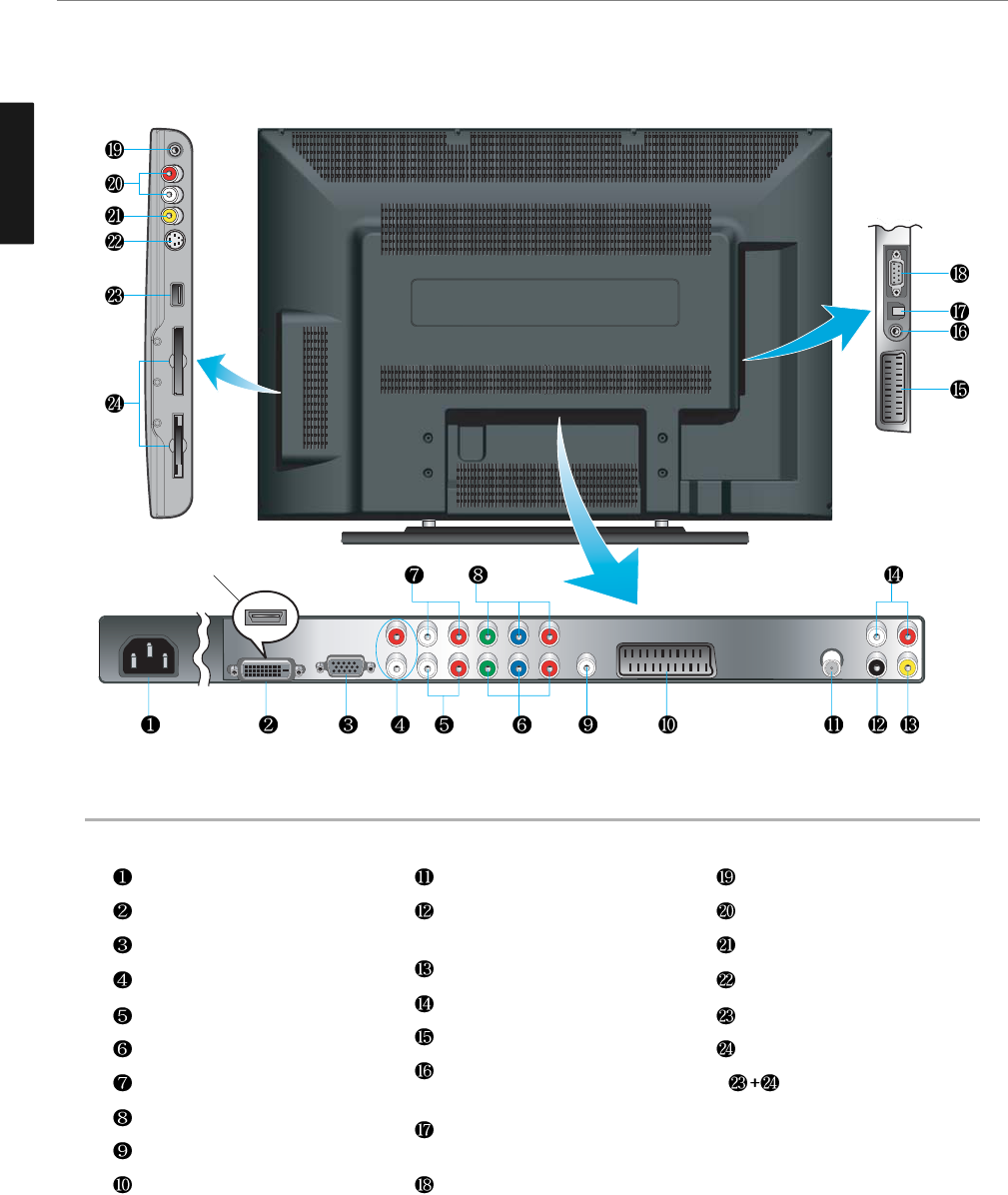
Rear View
Power (AC) input terminal
DVI Video / HDMI input terminal
D-SUB input terminal
DVI/D-SUB Audio input terminal
Component 2 Audio input terminal
Component 2 Video input terminal
Component 1 Audio input terminal
Component 1 Video input terminal
CVBS output terminal
Full Scart input terminal
Antenna input terminal
Digital Audio output terminal for
coaxial cable
Subwoofer output terminal
Extend Audio ontput terminal
Half Scart input terminal
Extend an RS-232 input for ATV
communication
SPDIF Optical audio output
terminal
Extend an RS-232 input for DTV
communication
Headphone output terminal
Audio(CVBS) input terminal
Video(CVBS) input terminal
S-Video input terminal
USB Input Terminal
Memory Card Slot
* For Q400 Model only
* This product image may be a bit different from the actual product.
HDMI Option
ENGLISH
16
General Information
Parts Names and Functions - 42”/50” PDP TV
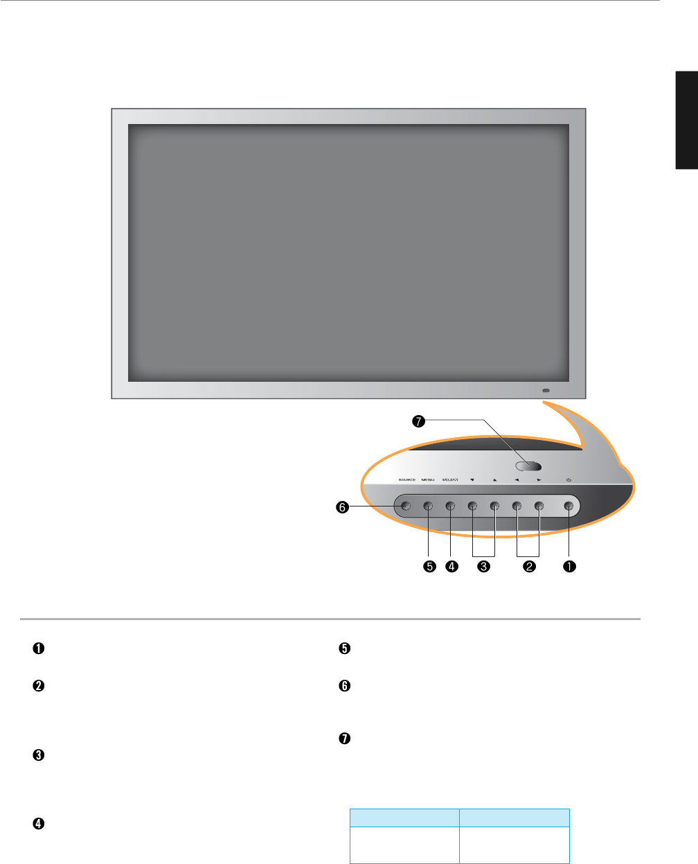
Front View
Power button
Use this button to turn on or off the TV.
Volume buttons
Use these buttons to adjust sound levels. These
buttons also serve as the cursors of Select/Adjust in
Menu mode.
Channel buttons
Use these buttons to change channels. These buttons
also serve as the cursors of Down and Up buttons in
Menu mode.
Select button
Use this button to select each item from the menu
mode.
Menu button
Use this button to display or exit from the menu mode.
Source button
Use this button to switch among inputs connected to
the TV.
Remote sensor and power LED.
- Point the remote control toward LED.
- It displays standby or operation status.
* This product image may be a bit different from the actual product.
- Power Indicator Status -
Indicator
Red
Green
Status
Standby
Power on
17
General Information
ENGLISH
Rear View
DVI Video input terminal
D-SUB input terminal
DVI/D-SUB Audio input terminal
Component 2 Audio input terminal
Component 2 Video input terminal
CVBS output terminal
Full Scart input terminal
S-Video input terminal
Audio(CVBS) input terminal
Headphone output terminal
Antenna input terminal
Digital Audio output terminal for
coaxial cable
Subwoofer output terminal
Half Scart input terminal
SPDIF Optical audio output
terminal
Extend an RS-232 input for DTV
communication
Power (AC) input terminal
Extend Audio ontput terminal
Video(CVBS) input terminal
Extend an RS-232 input for ATV
communication
Component 1 Video input terminal
Component 1 Audio input terminal
Power switch
Stand assembly
Speaker terminal
Speaker assembly
Screw hole for fixing on a wall
Carrying handles
* This product image may be a bit different from the actual product.
18
General Information
ENGLISH
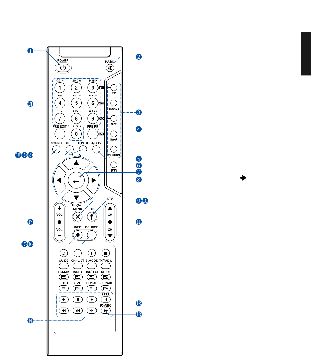
1. POWER/STANDBY
2. MUTE
This button is also used when setting up to use other external
devices.
3. PIP FUNCTIONS
- PIP
: Use this button for PIP On/Off.
- SOURCE
: Use this button to select the input source of sub-picture.
- SIZE
: Use this button to select the size of sub-picture.
- SWAP
: Use this button to swap main and sub-picture.
- POSITION
: Use this button to select the position of sub-picture.
4. PREVIOUS PROGRAM
5. A/D TV
Use this button to switch the input source from analog to
digital
6. Other external device selection ( 59P)
7. MENU SELECTION
Use this button to select menu items.
8. LEFT/RIGHT MOVE/ADJUST
- Use these buttons to move between menu items or adjust
each item.
- Use UP/DOWN buttons to select Analog TV channels.
9. MENU
Use this button to call the OSD on the screen.
10. EXIT
Use this button to end the OSD.
11. DTV CHANNEL SELECTION
You can also use these buttons when changing pages in TTX
mode.
12. STILL
13. PC-AUTO (For PDP TV only)
14. Use this buttons to use other manufacturer’s DVD or
VCR.
15. INFOMATION
Use this button to display resolution or various program.
16. SOURCE
Use this button to select External Input.
17. VOLUME
18. SOUND MODE
19. SLEEP
20. ASPECT RATIO
Use this button to change the picture size.
21. NUMERIC KEYS
Remote Control
19
General Information
ENGLISH
Power Saving Function when listening to music
Music Playback Setting (Repeat 1, Repeat All, Sequence)
Select, Start, Pause/Playback
Move between file listings, Previous Track/Next Track,
Reverse/Fast Forward, Photo Rotation
Exit, Cancel
Eject Card
Slide Show
Zoom In
Check Version (Initial Screen), Check Running Time (Movie Mode)
Hide Menu
When Shifting into Memory Mode
Other buttons available in Memory Mode
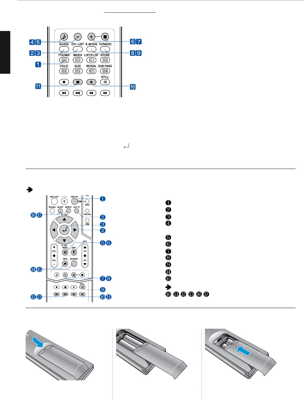
How to Insert Batteries in the Remote Controller * Battery type :1.5V/AAA
Using buttons when in Memory Mode -* For Q320, Q400 Model only
The following buttons are used differently in each menu. (See pages 51~58 for more details.)
Teletext & Fastext Function
(See pages 34 for more details.)
1. TTX/MIX
To see Teletext Service Data for Analog TV and Digital TV.
2. GUIDE (EPG-Electronic Program Guide)
To watch the program information. Press once more to return
to normal mode.
3. CH. LIST
To watch the channel list for Digital TV. Press key to
confirm or press EXIT to return to previous channels.
4. RED rubber
- DTV : To setup favorite channel lists in the Channel List menu.
- ATV : To delete a channel in the Program Edit menu.
5. GREEN rubber
- DTV : To lock favorite channel lists in the channel list menu.
- ATV : To sort channels in the Program Edit menu.
6. YELLOW rubber
- DTV : To move favorite channel lists in the channel list menu.
- ATV : To edit channel names in the Program Edit menu.
7. BLUE rubber
DTV : To delete a channel from the channel List menu. To show
extended program information in the EPG menu.
8. S.MODE
To adjust the subtitle and audio condition/status of the current
channel for Digital TV
9. TV-RADIO
To switch between the TV channel and radio channel for
Digital TV.
10. WHITE rubber
DTV : To add a new channel to the Channel List menu.
11. ORANGE rubber
DTV : To see variant channel lists for user’s convenience in the
Channel List menu.
Press and hold Δpart and push to open
cover.
Insert batteries with proper polarities of
+ and -.
Use the remote control with cover closed.
123
20
Connections
ENGLISH
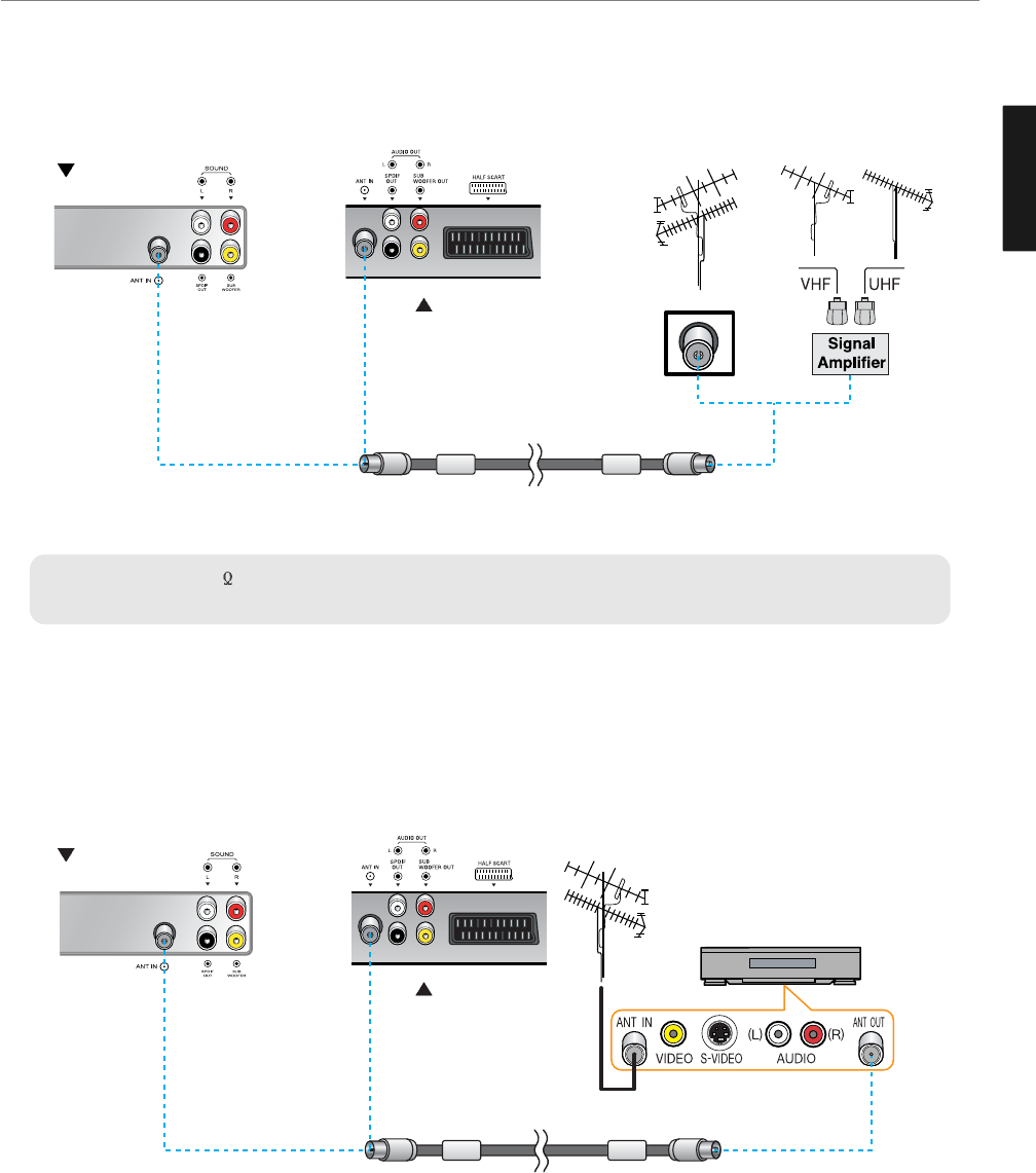
✓
When inserting a 75 ohm coaxial cable into the input connection, ensure the wire tip not to bend.
✓
If you experience poor signal reception, we recommend you purchase a signal amplifier for better picture quality.
VHF Antenna
UHF Antenna
Antenna cable
Connecting Indoor/Outdoor TV Antenna(UHF/VHF)
- Antenna or Cable service without cable box connections
- For on optimum picture quality, adjust the direction of antenna if needed.
VCR/Cable Receiver
Connecting Antenna Input Connection to External Equipments
1. Connect an antenna cable to VCR/Cable/Satellite Receiver with the antenna input.
2. Use a coaxial cable to connect VCR/Cable/Satellite Receiver's antenna output to the antenna input on your TV.
Antenna cable
26”/32”/40”
TV
42”/50” TV
26”/32”/40”
TV
42”/50” TV
21
Connections
ENGLISH
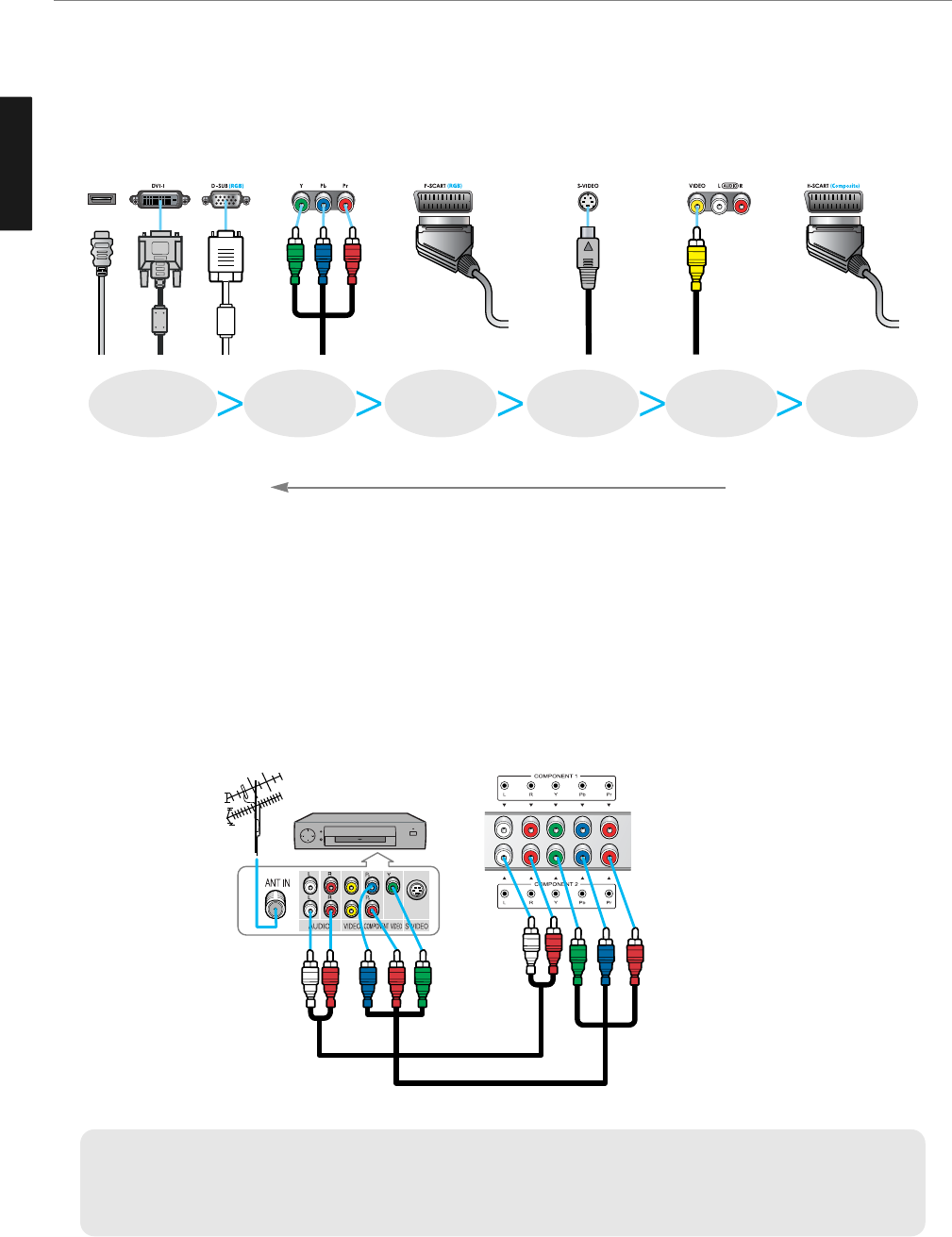
Before Connecting the Video/Audio Connections to External Devices...
Please make sure to read the following instruction to enjoy the best picture quality.
Best picture quality is displayed in the following order.
The superior picture quality starts from the far left side.
✓
Output terminal mark (Y, Pb, and Pr) of DVD player may be indicated as Y, B-Y, R-Y/Y-Cb-Cr /Y-Pb-Pr according to the
type of DVD player models.
✓
If your DVD player or Set Top Box supports HDMI/DVI or D-SUB, see Connecting to a PC (page 22) for connection. You
can enjoy more clear picture quality.
DTV receiver
/ DVD Player
Audio cable
Video (Y, Pb, Pr) cable
How to Connect a DTV Receiver or DVD Player
1. Connect the Video cable (Y, Pb, Pr) between output terminals (Y, Pb, Pr) of DTV receiver or DVD player and the
input terminals (Y, Pb, Pr) of DTV/DVD (576i/576p/720p/1080i) on the rear of TV.
(Connect the jacks to terminals in the same color.)
2. Connect the Audio cable between Audio output terminals of DTV receiver or DVD player and Audio input terminal
for DTV/DVD Audio on the rear of TV. (Connect the jacks to terminals in the same color.)
HDMI
FULL SCART
HDMI,
DVI-1, D-Sub COMPONENT S-VIDEO COMPOSITE HALF SCAT
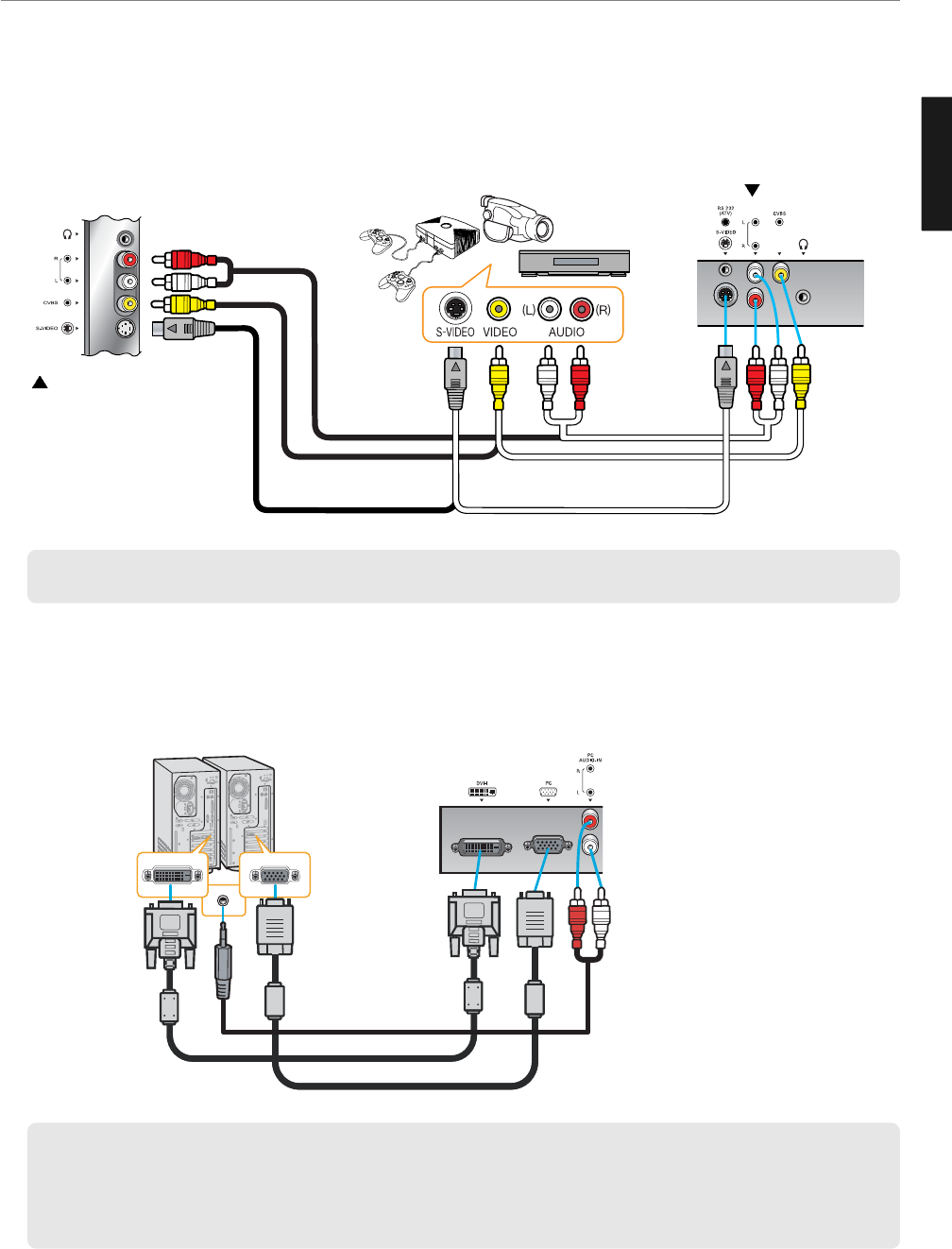
How to Connect to a PC
1. Connect the PC signal cable (15-pin D-sub) between the output terminal of PC and the D-sub input terminal of TV.
2. Connect the Audio cable between Audio output terminal of PC and Audio input terminal for PC on the rear of TV.
(Connect the jacks to terminals in the same color.)
✓If you use DVI/HDMI connection, you can enjoy better picture quality.
✓This product supports Plug-and-Play function.
✓We recommend the above method if the DVD player or set top box supports DTV signal with DVI/D-sub (15 pin) cable
for better picture quality.
✓If you input an unsupported resolution in PC or DVI/HDMI mode, the screen won’t be displayed properly.
How to Connect a VCR, Cable Receiver, Camcoder, Game Player
1. Connect the Video cable or S-Video cable between Video/S-Video output terminals of VCR or Cable receiver and
Video/S-Video input terminal of TV. (Connect the jacks to terminals in the same color.)
2. Connect the Audio cable (Left: white, Right: red) between Audio output terminals of VCR or cable receiver and
Audio input terminal of TV. (Connect the jacks to terminals in the same color.)
✓ To enjoy a better picture quality, use the S-Video cable rather than the composite cable.
DVI cable (DIGITAL)
D-SUB cable
Audio Cable
or
Video cable or
S-Video Cable
Video cable or
S-Video Cable
Game Player
Camcorder
Video
/Cable receiver
Audio cable Audio cable
26”/32”/40” TV
42”/50” TV
22
Connections
ENGLISH
23
Connections
ENGLISH
Resolutions Supported in PC
Vertical frequency
70.00
-
72.80
75.00
-
-
70.08
60.32
75.00
72.19
74.55
60.00
70.07
75.03
60.02
74.99
Horizontal frequency
31.47
-
37.86
31.50
-
-
31.47
37.88
46.88
48.08
49.73
48.36
56.48
60.02
63.98
61.27
Vertical frequency
70.09
85.08
59.94
72.80
75.00
85.01
70.08
60.32
72.18
75.00
85.06
74.55
60.00
75.03
85.00
-
-
Horizontal frequency
31.47
37.86
31.47
37.86
37.50
43.27
31.47
37.88
48.08
46.88
53.67
49.72
48.36
60.02
68.68
-
-
Model
Resolution
640 x 350
640 x 480
720 x 400
800 x 600
832 x 624
1024 x 768
1280 x 1024
1366 x 768
26” / 32” / 40” LCD TV 42” / 50 PDP TV
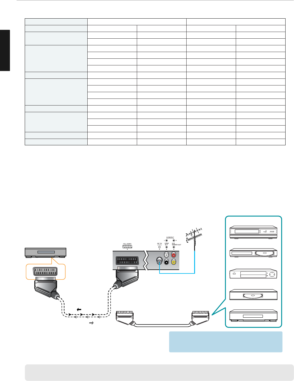
Scart Connection to the External Input/Output
If you have a second VCR and wish to copy casettes tape. Connect the source VCR to “F Scart” and the target VCR
to “H Scart” so that you can redirect the signal from “F Scart” to “H Scart”.
* “F Scart” sends the TV broadcast signal received through an antenna to a set-top box and receives the
descrambled signal back, which allows you to view TV broadcasts in AV Mode.
* “H Scart” you are capable to record live TV broadcasts on the TV screen. (Please make sure that your TV is “ON”.)
✓When switching voltage comes into the Scart-Pin 8 during viewing a TV program, the current mode will be switched
to Scart mode.
F SCART
SET TOP BOX
VIDEO(CVBS)
+ Audio(L/R)
TV OUT
TV IN
- F Scart Input : RGB, CVBS - F Scart Output : CVBS
- H Scart Input : CVBS - H Scart Output : CVBS
Video Game Device
Video Disc Player
Satellite Receiver
DVD
VCR
*1. HDMI, the HDMI logo and High-Definition Multimedia Interface are trademarks or registered trademarks of HDMI
Licensing LLC.
*2. EIA/CEA-861/861B profiles compliance covers profiles for transmission of uncompressed digital video including high
bandwidth digital content protection.
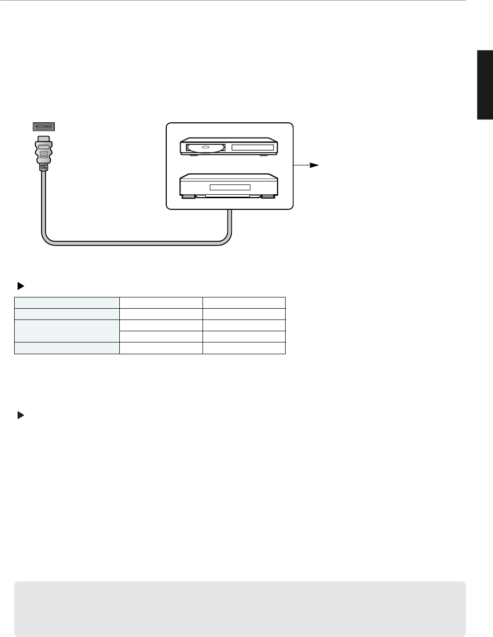
HDMI Connection (For HDMI model only)
HDMI*1(High Definition Multi media Interface) is the first all digital consumer electronics A/V interface that supports
uncompressed standard. The HDMI terminal supports both video and audio information.
To the HDMI™ input terminal, you can connect an EIA/CEA-861/861*2compliant consumer electronic device, such
as a Set Top Box or DVD player with HDMI or DVI output terminal.
Compatible VIDEO Signal
- This input terminal is not intended for use with computers.
Compatible sampling freguency of AUDIO signal through HDMI (L.PCM) : 48kHz / 44.1kHz / 32 kHz
➥ Notes :
• This HDMI connector is Type A.
• If you connect an equipment without a digital output terminal, connect to the COMPONENT VIDEO, S VIDEO or
VIDEO input terminal on the TV so you can enjoy an analog signal.
• The DIGITAL IN terminal can only be used with 1080i, 720p or 576p picture signals. Set the Digital Set -Top -Box
DIGITAL OUT terminal Output setting to 1080i, 720p or 576p. For detailed information, refer to the Digital Set -Top
- Box instruction manual. If you cannot display the picture because your Digital Set -Top -Box does not have a
DIGITAL OUT terminal Output setting, use the component Video Input (or the S Video Input or Video Input). In this
case the picture will be displayed as an analog signal.
HDMI
HDMI Cable
Set Top Box
DVD Player
If the external device has DVI
output only, use a DVI to HDMI
adapter cable to connect to the
HDMI terminal.
50
50
50
50
1,920 x 1,080i
720 x 576p
640 x 576p
1280 x 720p
Model
1080i
576p
720p
Resolution Vertical frequency
24
Connections
ENGLISH
25
Connections
ENGLISH
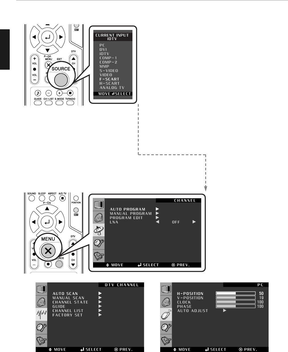
Different OSD Menu
You can confirm OSD menu of three different type.
How to Set the OSD Screen
PC : For supporting Personal Computer connection.
DVI* : Digital Visual Interface for using TMDS transmission
reduces the loss of signal.
➥ *Notes : “DVI” is changed to “HDMI” in HDMI
model.
HDMI* : High Definition Multi media Interface that supports
both video and audio information.
COMP-1 / COMP-2 : For supporting greater color accuracy than
composite video or S-VIDEO by splitting
chrominance into one video signal.
S-VIDEO : For supporting better resolution than composite video,
which carries the signals together.
VIDEO : For supporting the color shade(chrominance) and
brightness(luminance) information into one video signal.
F-SCART - For supporting composite video and RGB video
signals. SCART connectors is used with many
European video equipments.
H-SCART - Basically the same as Full SCART in function but not
supporting RGB Video signals.
ANALOG TV - Terrestrial broadcasting for supporting analog
PAL/SECAM system.
✓ The menu button “EXIT” or
“PREV.” may occur
depending on the model.
✓ In case of the source in
Analog TV, S-VIDEO, VIDEO,
F-SCART, H-SCART
✓ In case of the source in iDTV ✓ In case of the source in PC, DVI,
COMP-1, COMP-2
ENGLISH
26
Picture Setup
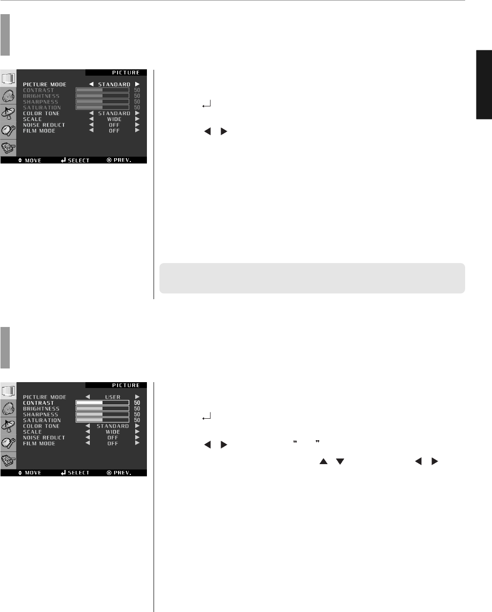
Press MENU button.
Menu items appear on the screen.
Press button to select “Picture” Icon.
“PICTURE MODE” is highlighted.
Press / buttons, then the menu changes in the following order.
➛STANDARD ➛DYNAMIC ➛MOVIE ➛MILD ➛USER ➛
Press EXIT button to TV viewing or press MENU button to return to the previous
menu.
♦ STANDARD : Most video contents are appropriate to this mode.
♦ DYNAMIC : Clear display
♦ MOVIE : When watching a movie
♦ MILD : Soft display.
♦ USER : When the user wants to set the values directly.
✓ In the user’s mode, the users can adjust their desired contrast, brightness,
sharpness, hue, saturation.
How to Select the Picture Mode
Users can automatically adjust the picture mode according to the input mode.
How to Set the Desired Picture
Users can manually adjust their desired picture
Press MENU button.
Menu items appear on the screen.
Press button to select “Picture” Icon.
“PICTURE MODE” is highlighted.
Press / buttons to select USER .
Select required option by pressing the / button, then Press / button
to adjust.
Press EXIT button to TV viewing or press MENU button to return to the previous
menu.
♦ CONTRAST : Adjust the brightness and darkness of the object and backgrounds.
♦ BRIGHTNESS : Adjust the brightness of the entire picture.
♦ SHARPNESS : Adjust the clarity of object outlines.
♦ SATURATION : Adjust colors into deeper or lighter colors.
1
3
4
2
1
2
3
4
5
ENGLISH
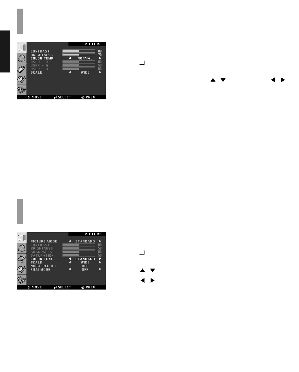
Press MENU button.
Menu items appear on the screen.
Press button to select “Picture” Icon.
“CONTRAST” is highlighted.
Select required option by pressing the / buttons, then Press /
buttons to adjust.
After selecting COLOR TEMP, then the menu changes in the following order.
➛NORMAL ➛WARM ➛COOL ➛sRGB ➛USER ➛
Press EXIT button to TV viewing or press MENU button to return to the previous
menu.
♦ NORMAL : For a general Color Tone.
♦ WARM : For warm colors with reddish tone.
♦ COOL : For cool colors with bluish tone.
♦ USER : When the user wants to set the degree of RGB directly.
Press MENU button.
Menu items appear on the screen.
Press button to select “Picture” Icon.
“PICTURE MODE” is highlighted.
Press / buttons to move to “COLOR TONE”.
Press / buttons, then the menu changes in the following order.
➛STANDARD ➛WARM ➛COOL ➛
Press EXIT button to TV viewing or press MENU button to return to the previous
menu.
♦ STANDARD : For a general Color Tone.
♦ WARM : For warm colors with reddish tone.
♦ COOL : For cool colors with bluish tone.
How to Set the Desired Picture in PC, DVI/HDMI Input Modes
Users can adjust Color as users want.
How to Select a Color Temperature
Users can adjust Color as users want.
1
1
3
4
5
2
27
Picture Setup
3
4
2
ENGLISH
28
Picture Setup
How to Set the Display Scale
Users can adjust the display scale as they want
Press MENU button.
Menu items appear on the screen.
Press button to select “Picture” Icon.
“PICTURE MODE” is highlighted.
Press / buttons to move to “SCALE”.
Press / buttons, then the mode change in the following order.
➛WIDE ➛ZOOM1 ➛ZOOM2 ➛4:3 ➛14:9 ➛
Press EXIT button to TV viewing or press MENU button to return to the previous
menu.
♦ WIDE - General broadcast picture is adjusted to 16:9.
♦ ZOOM 1 - Picture enlarged to 16:9 format, letter box format.
♦ ZOOM 2 - Zoom in 16:9 in vertical direction
♦ 4:3 - 4:3 general picture size
♦ 14:9 - 14:9 picture size
1
3
4
5
2
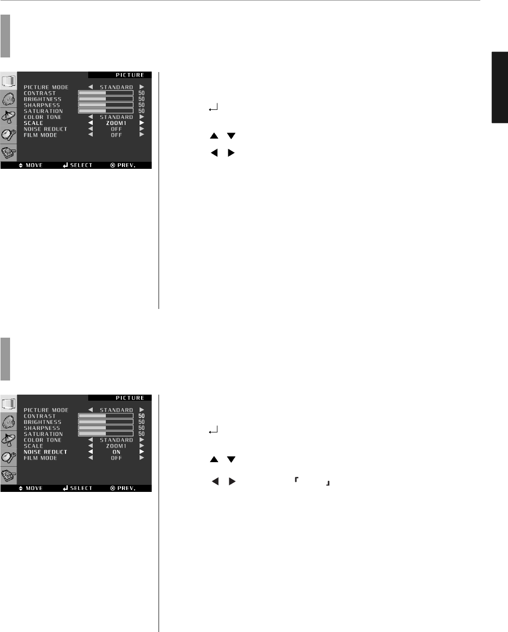
Press MENU button.
Menu items appear on the screen.
Press button to select “Picture” Icon.
“PICTURE MODE” is highlighted.
Press / buttons to move to “NOISE REDUCT”.
Press / buttons to set ON/OFF .
Press EXIT button to TV viewing or press MENU button to return to the previous
menu.
1
2
How to Set Noise Reduction
User can eliminate noises on the screen in Video mode
3
4
5