ICOM orporated 272102 UHF-FM Trunked Radio Transceiver User Manual Manual
ICOM Incorporated UHF-FM Trunked Radio Transceiver Manual
UserManual.wiki
>
ICOM orporated
>
272102 User Manual
>
Manual
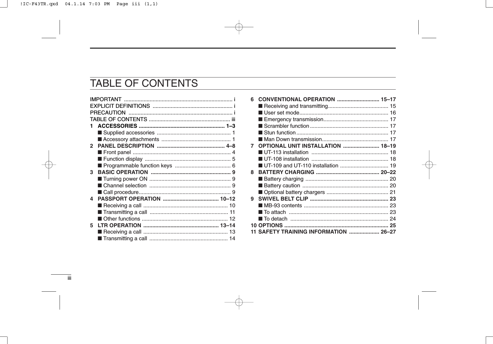
Contents
1.
Manual
2.
Updated User Manual
Manual
Navigation menu
Upload a User Manual
Namespaces
Wiki Guide
HTML
PDF
Info
Views
User Manual
Discussion / Help
Navigation
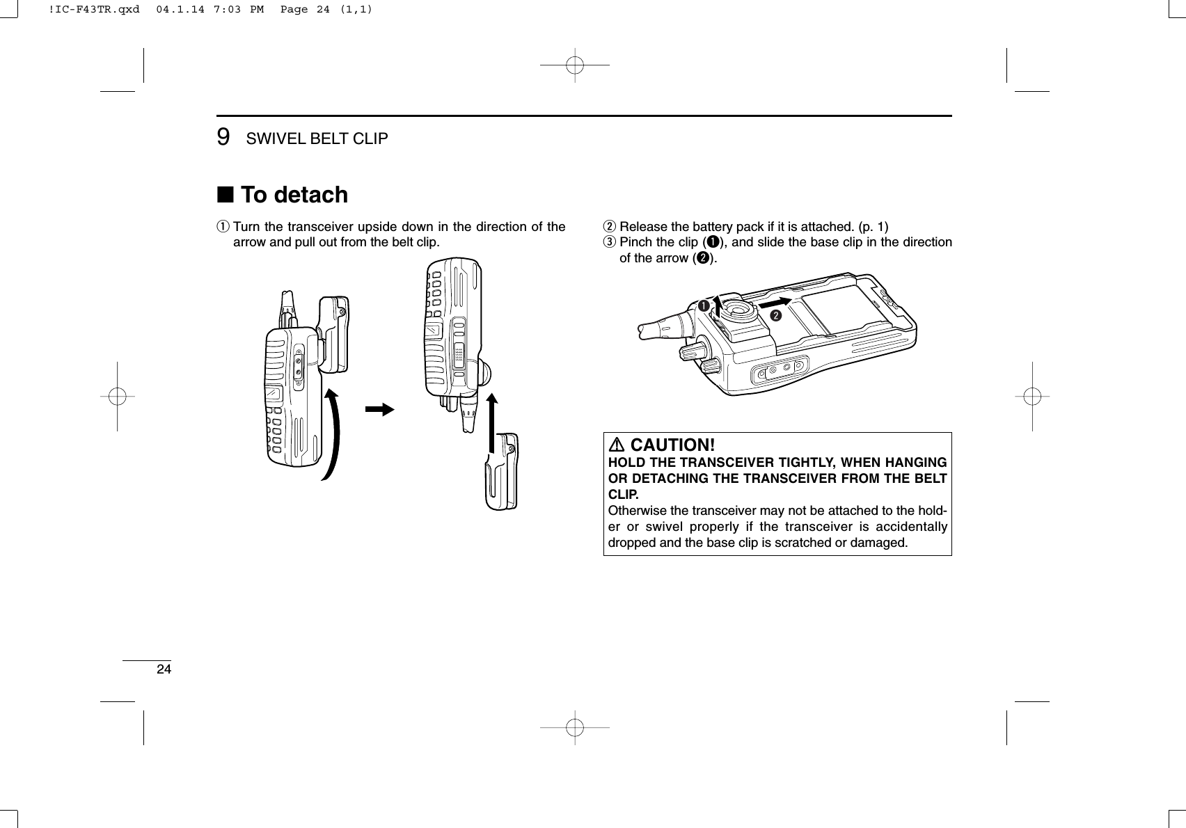
![31ACCESSORIESïJack coverAttach the jack cover when the optional speaker-microphoneis not used.qwqwTo attach the jack cover:qAttach the jack cover onthe [SP MIC] connector.wTighten the screws.To detach the jack cover:qUnscrew the screw with aPhillips screwdriver.wDetach the jack cover forthe speaker-microphoneconnection.!IC-F43TR.qxd 04.1.14 7:03 PM Page 3 (1,1)](https://usermanual.wiki/ICOM-orporated/272102.Manual/User-Guide-406302-Page-7.png)
![42PANEL DESCRIPTION■Front panelqROTARY SELECTORSelects the pre-programmed system channels or talkgroups (Max. 16) on the LTR/Passport system.(Depending on the pre-setting)wVOLUME CONTROL [VOL]Turns power ON and adjusts the audio level.eEMERGENCY KEYPush to transmit the DTMF emergency call.r[SP]/[MIC] JACKConnect the optional speaker-microphone. • Attach the jack cover when the optional speaker-microphone isnot used. (p. 3)tFUNCTION DISPLAYDisplays a variety of information such as operating chan-nel name, DTMF encode channel, selected function, etc.yDEALER-PROGRAMMABLE KEYS [P0] to [P3]Desired functions can be programmed independently byyour dealer.u10-KEYPAD (Depending on version)Used to enter DTMF encode channel, phone number, etc.iUP/DOWN [∫∫]/[√√] KEYS➥Push to select the operating channel.➥Push to select the talk group on the LTR or Passportsystem.oPTT SWITCH [PTT]Push and hold to transmit; release to receive.!0 MONITOR KEYPush to mute and release the CTCSS (DTCS) squelchmute. Open squelch/deactivate mute while pushing thiskey.!1 ANTENNA CONNECTORConnects the supplied antenna.itrqeuyw!1!0o10-keypad version!IC-F43TR.qxd 04.1.14 7:03 PM Page 4 (1,1)](https://usermanual.wiki/ICOM-orporated/272102.Manual/User-Guide-406302-Page-8.png)
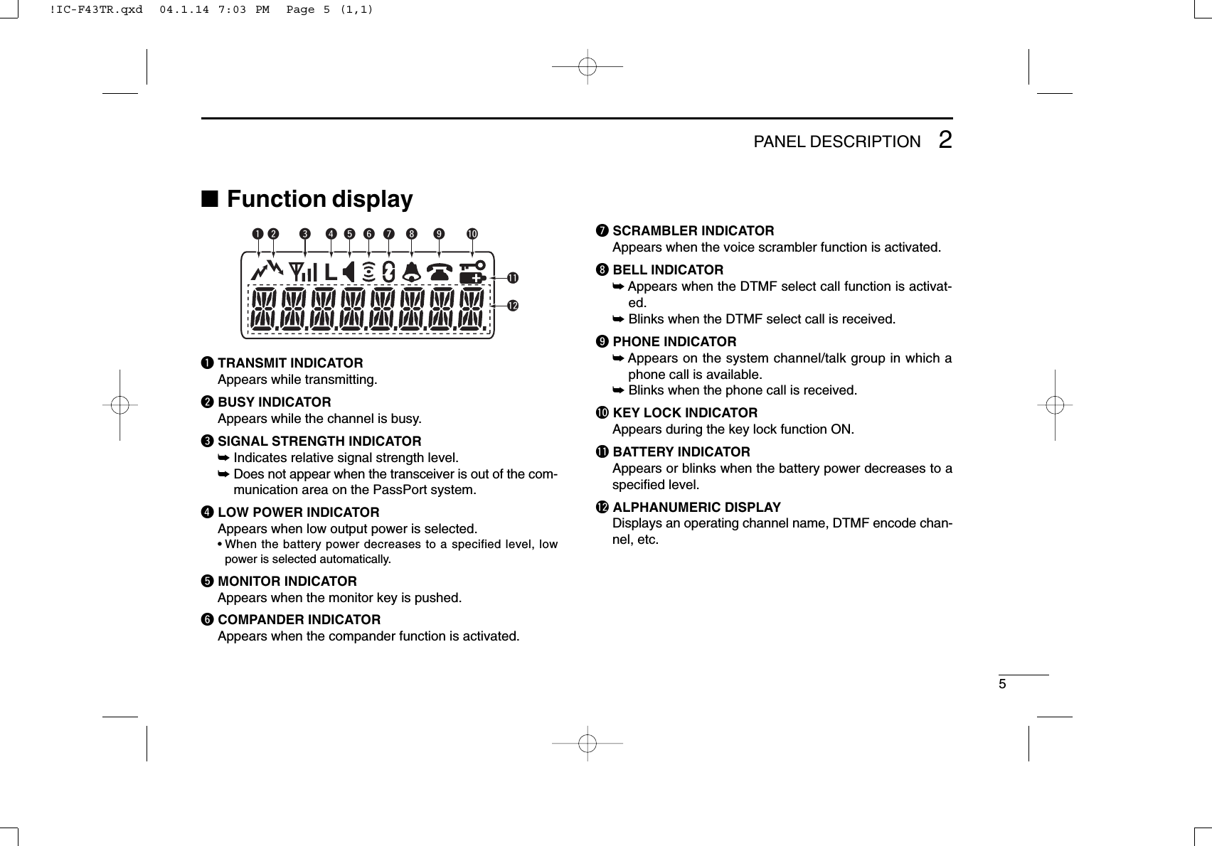
![62PANEL DESCRIPTION■Programmable function keysThe following functions can be assigned to [P0], [P1], [P2],[P3], [Emergency], [Monitor], [MM]* and [#]* programmablefunction keys. Consult your Icom dealer or system operator for details con-cerning your transceivers programming.If the programmable function names are bracketed in the fol-lowing explanations, the specific key used to activate thefunction depends on programming.*Available on 10-keypad version only.SEND DTMF KEYPush to enter the DTMF encode channel selection mode.SELECT CALL KEY➥Push to turn the DTMF select call mute function ON.➥Push and hold to turn the DTMF select call mute functionOFF.PRIORITY KEYPush to select the priority channel.EMERGENCY KEYPush to select the priority channel and automatically transmita DTMF emergency call code.SCAN A KEY➥This key’s operation depends on the Power ON Scan set-ting.When the power ON scan function is turned OFF;Push to start and cancel scanning operation. In case oftransmission during scan, cancels scanning.When the power ON scan function is turned ON;Push to pause scanning. Scanning resumes after passinga specified time period. In case of transmission duringscan, pauses scanning. Scanning resumes after passinga specified time period specified.➥Push and hold this key for 1 sec. to indicate the scangroup, then push to select the desired group.SCAN B KEY➥Push to start and cancel scanning operation. In case oftransmission during scan, pauses scanning. Scanningresumes after passing a specified time period. ➥Push and hold this key for 1 sec. to indicate the scangroup, then push to select the desired group.PRIORITY CHANNEL KEYS➥Push to select Priority A or Priority B channel.➥Push and hold [Prio A (Rewrite)] to rewrite the Prio Achannel.!IC-F43TR.qxd 04.1.14 7:03 PM Page 6 (1,1)](https://usermanual.wiki/ICOM-orporated/272102.Manual/User-Guide-406302-Page-10.png)
![72PANEL DESCRIPTIONMONITOR KEYPush to mute and release the CTCSS (DTCS) squelch mute.Open squelch/deactivate mute while pushing this key.NUISANCE DELETE KEYPush to cancel the displayed channel from the scan list in thetalk group.SCAN TYPE KEYPush to toggle the scan type from Individual or Block.SPEED DIAL KEYPush to send the most recently transmitted DTMF codeselected with [Send DTMF].TALK AROUND KEYTurn the talk around function ON and OFF. This function equalizes the transmit frequency to the receivefrequency for transceiver-to-transceiver communication.WIDE/NARROW KEYPush to toggle the IF passband width from “Wide” or “Narrow”channel spacing for both transmission and reception tem-porarily. Once the channel or bank has changed, the pass-band width returns to the original setting.TX POWER KEYPush to toggle the transmit output power level from the inde-pendent settings of each channel.RE-DIAL KEYPush to send the most recently transmitted DTMF code edit-ed with 10-keypad.RSSI KEYPush to display the RSSI (Received Signal Strength Indicator)level.MODE DISPLAY TYPE KEYPush to toggle the scan mode display type from Individualand Block.LOCK KEYPush and hold for 2 sec. to turn the lock function ON andOFF.• User Password is prompted to turn the lock function OFF. See p. 9for details of password input.PHONE REQUEST KEYPush to turn the phone call function ON and OFF in the oper-ating channel.!IC-F43TR.qxd 04.1.14 7:03 PM Page 7 (1,1)](https://usermanual.wiki/ICOM-orporated/272102.Manual/User-Guide-406302-Page-11.png)
![82PANEL DESCRIPTIONROAM REQUEST KEY➥Push to return to the home site.➥Push and hold to start roaming.SITE LOCK KEYPush to turn the Site Lock function ON and OFF. This function inhibits automatic roaming, and can be usefulwhen the transceiver is out of the communication area suchas on a subway or in an elevator.EMERGENCY SINGLE/REPEAT KEYPush for the specified time period to select the emergencychannel and automatically send a DTMF emergency signalonce or repeatedly.SCRAMBLER KEYPush to toggle the scrambler function ON or OFF.COMPANDER KEYPush to turn the compander function ON and OFF.The compander function reduces noise components from thetransmitted audio to provide clear communication.USER SET MODE KEYPush for 1 sec. to enter the User set mode.The User set mode allows you to set seldom-changed set-tings.Push this key momentarily in the User set mode to select thefunction, and push [CH Up] or [CH Down] to change the set-ting.SIREN KEYPush to emit a siren. This function can be used for situationssuch as a security alarm for example.MODE SELECT KEY (available for Passport/LTR only)Push to select the operating mode from System or Group.!IC-F43TR.qxd 04.1.14 7:03 PM Page 8 (1,1)](https://usermanual.wiki/ICOM-orporated/272102.Manual/User-Guide-406302-Page-12.png)
![93BASIC OPERATION■Turning power ONqRotate [VOL] to turn the power ON.wIf the transceiver is programmed for a start up passcode,input the digit codes as directed by your dealer.• The keys in the table below can be used for password input:• The transceiver detects numbers in the same block as identical.Therefore “01234” and “56789” are the same.eWhen the “PASSWORD” indication does not clear afterinputting 4 digits, the input code number may be incorrect.Turn the power off and start over in this case.■Channel selectionPush [UP] or [DOWN], or rotate [ROTARY SELECTOR] toselect the desired system channel or talk group, in sequence.• Up to 16 pre-programmed channels can be selected via [ROTARYSELECTOR].■Call procedureWhen your system employs tone signalling (excludingCTCSS and DTCS), the call procedure may be necessaryprior to voice transmission. The tone signalling employed maybe a selective calling system which allows you to call specificstation(s) only and prevent unwanted stations from contact-ing you.qSelect the desired DTMF encode channel according toyour System Operator’s instructions.• This may not be necessary depending on programming.• Refer to pgs. 11, 14, 16 for selection.wPush the [PTT].eAfter transmitting a DTMF code, the remainder of yourcommunication can be carried out in the normal fashion.Selective calling Non-selective callingKEYNUMBER 0549382716UP!IC-F43TR.qxd 04.1.14 7:03 PM Page 9 (1,1)](https://usermanual.wiki/ICOM-orporated/272102.Manual/User-Guide-406302-Page-13.png)
![104PASSPORT OPERATION■Receiving a callDGroup callqPush [UP] or [DOWN], or rotate [ROTARY SELECTOR]to select the Passport system channel or talk group.wWhen a call is received;•“ ” and the calling station name/ID appear.ePush and hold [PTT], then speak into the microphone ata normal voice level.rRelease [PTT] to return to receive.DIndividual callqPush [UP] or [DOWN], or rotate [ROTARY SELECTOR]to select the Passport system channel or talk group.wWhen a call is received;•“ ” and the calling station name/ID appear.ePush and hold [PTT], then speak into the microphone ata normal voice level.rRelease [PTT] to return to receive.tTo finish the conversation, push [DOWN] to send the“Clear Down” signal.DSelective call (DTMF call)—Optional UT-108 is required—qPush [UP] or [DOWN], or rotate [ROTARY SELECTOR]to select the Passport system channel or talk group.wPush [Select call] to mute the channel.•“ ” appears.eWhen receiving a call, the calling station name appearsand a beep is emitted. Then the mute is released.•“ ” disappears.DPhone callqPush [UP] or [DOWN], or rotate [ROTARY SELECTOR]to select the Passport system channel or talk group.wWhen a phone call is received (transceiver rings), pushand hold [PTT], then speak into the microphone at a nor-mal voice level.•“ ” blinks and calling station name/ID appears for 1 sec.eRelease [PTT] to return to receive.rPush [#] while pushing [PTT] to finish the communication.BlinksAppears!IC-F43TR.qxd 04.1.14 7:03 PM Page 10 (1,1)](https://usermanual.wiki/ICOM-orporated/272102.Manual/User-Guide-406302-Page-14.png)
![114PASSPORT OPERATION■Transmitting a callDGroup callqPush [UP] or [DOWN], or rotate [ROTARY SELECTOR]to select the Passport system channel or talk group inwhich the group ID is pre-programmed.wWhile pushing and holding [PTT], speak into the micro-phone at a normal voice level after a beep is emitted.• If an error beep is emitted, release [PTT]. After a while, repeatstep wagain.• The beep can be turned OFF in User set mode.•When the transceiver is out of the communication area, “”disappears, and “NO SVC” message appears.DIndividual callqPush [UP] or [DOWN], or rotate [ROTARY SELECTOR]to select the Passport system channel or talk group inwhich the MID (Mobile ID) is pre-programmed.wWhile pushing and holding [PTT], speak into the micro-phone at a normal voice level after a beep is emitted.• If an error beep is emitted, release [PTT]. After a while, repeatstep wagain.• The beep can be turned OFF in User set mode.•When the transceiver is out of the communication area, “”disappears, and “NO SVC” message appears.eTo finish the conversation, push [DOWN] to send the“Clear Down” signal.DSelective call (DTMF call)—Optional UT-108 is required—qPush [UP] or [DOWN], or rotate [ROTARY SELECTOR]to select the Passport system channel or talk group.wPush [Send DTMF]— a DTMF encode channel appears.ePush [UP] or [DOWN] to select the desired DTMF encodechannel.rPush [PTT] to transmit the selected DTMF code in theselected DTMF channel.• Push [P0] to cancel the DTMF transmission.DPhone call (Available for 10-keypad version only)qPush [UP] or [DOWN], or rotate [ROTARY SELECTOR]to select the Passport system channel or talk group.wPush [Phone request] to enable the phone call.•“ ” appears.ePush [PTT] to connect the phone line.•The proceed tone is emitted after connection to the phone line.rWhile pushing and holding [PTT], enter the phone numbervia the 10-keypad to make the call. Then release [PTT].tPush [PTT] to transmit; release to receive.yPush [#] while pushing [PTT] to finish the communication.Appears!IC-F43TR.qxd 04.1.14 7:03 PM Page 11 (1,1)](https://usermanual.wiki/ICOM-orporated/272102.Manual/User-Guide-406302-Page-15.png)
![124PASSPORT OPERATION■Other functionsDManual roaming start function If the transceiver has [Roam Request] assigned to it, youcan start roaming manually to search for another site.qPush [UP] or [DOWN], or rotate [ROTARY SELECTOR]to select the Passport system channel or talk group.wPush and hold [Roam Request] to start roaming.•“ROAMSITE” is displayed.•When “INVALID” is displayed, the home repeater may not have aneighbour site. After a while, repeat step w.ePush [Roam Request] to cancel roaming.DSite lock functionIf the transceiver has [Site Lock] assigned to it, automaticroaming can be inhibited. This function is useful when thetransceiver is out of the communication area such as on asubway or in an elevator.qPush [UP] or [DOWN], or rotate [ROTARY SELECTOR]to select the Passport system channel or talk group.wPush [Site Lock] to turn the site lock function ON andOFF.•“SITELOCK” is displayed.!IC-F43TR.qxd 04.1.14 7:03 PM Page 12 (1,1)](https://usermanual.wiki/ICOM-orporated/272102.Manual/User-Guide-406302-Page-16.png)
![135LTR OPERATION■Receiving a callDGroup callqPush [UP] or [DOWN], or rotate [ROTARY SELECTOR]to select the LTR system channel or talk group.wWhen a call is received;•“ ” and the calling station name/ID appear.ePush and hold [PTT], then speak into the microphone ata normal voice level.rRelease [PTT] to return to receive.DSelective call (DTMF call)—Optional UT-108 is required—qPush [UP] or [DOWN], or rotate [ROTARY SELECTOR]to select the LTR system channel or talk group.wPush [Select call] to mute the channel.•“ ” appears.eWhen receiving a call, the calling station name appearsand a beep is emitted. Then the mute is released.•“ ” disappears.DPhone callqPush [UP] or [DOWN], or rotate [ROTARY SELECTOR]to select the LTR system channel or talk group.wWhen a phone call is received (transceiver rings), pushand hold [PTT], then speak into the microphone at a nor-mal voice level.•“ ” blinks and calling station name/ID appears for 1 sec.eRelease [PTT] to return to receive.rPush [#] while pushing [PTT] to finish the communication.BlinksAppears!IC-F43TR.qxd 04.1.14 7:03 PM Page 13 (1,1)](https://usermanual.wiki/ICOM-orporated/272102.Manual/User-Guide-406302-Page-17.png)
![145LTR OPERATION■Transmitting a callDGroup callqPush [UP] or [DOWN], or rotate [ROTARY SELECTOR]to select the LTR system channel or talk group.wWhile pushing and holding [PTT], speak into the micro-phone at a normal voice level after a beep is emitted.• If an error beep is emitted, release [PTT]. After a while, repeatstep w.• The beep can be turned OFF in User set mode.DSelective call (DTMF call)—Optional UT-108 is required—qPush [UP] or [DOWN], or rotate [ROTARY SELECTOR]to select the LTR system channel or talk group.wPush [Send DTMF]— a DTMF encode channel appears.ePush [UP] or [DOWN] to select the desired DTMF encodechannel.rPush [PTT] to transmit the selected DTMF code in theselected DTMF channel.• Push [Send DTMF] to cancel the DTMF transmission.!IC-F43TR.qxd 04.1.14 7:03 PM Page 14 (1,1)](https://usermanual.wiki/ICOM-orporated/272102.Manual/User-Guide-406302-Page-18.png)
![156CONVENTIONAL OPERATION■Receiving and transmittingNOTE: Transmitting without an antenna may damage thetransceiver. See p. 1 for antenna attachment.Receiving:qRotate [VOL] to turn the power ON.wPush [UP] or [DOWN], or rotate [ROTARY SELECTOR]to select the conventional system channel, in sequence.eWhen receiving a call, adjust the audio output level to acomfortable listening level.Transmitting:Wait for the channel to become clear to avoid interference.qWhile pushing and holding [PTT], speak into the micro-phone at a normal voice level.wRelease [PTT] to return to receive.IMPORTANT: To maximize the readability of your signal;1. Pause briefly after pushing [PTT].2. Hold the microphone 5 to 10 cm (2 to 4 inches) fromyour mouth, then speak into the microphone at a normalvoice level.DTransmitting notes• Transmit inhibit functionThe transceiver has several inhibit functions which restricttransmission under the following conditions:- Channel is busy.- Un-matched (or matched) CTCSS is received.- The selected channel is a ‘receive only’channel.• Time-out timerAfter continuous transmission for the pre-programmed timeperiod, the time-out timer is activated, causing the transceiv-er to stop transmitting.• Penalty timerOnce the time-out timer is activated, transmission is furtherinhibited for a period determined by the penalty timer.!IC-F43TR.qxd 04.1.14 7:03 PM Page 15 (1,1)](https://usermanual.wiki/ICOM-orporated/272102.Manual/User-Guide-406302-Page-19.png)
![166CONVENTIONAL OPERATIONDDTMF receiving and transmitting —Optional UT-108 is required—If the transceiver has [Send DTMF] assigned to it, a DTMFencode channel is displayed when pushed, and assignedDTMF encode channels can be selected via [UP] or [DOWN].Receiving:qPush [UP] or [DOWN], or rotate [ROTARY SELECTOR]to select the conventional system channel, in sequence.wPush [Select call] to mute the channel. (“” appears)eWhen receiving a call, a beep is emitted and mute isreleased. (“” disappears)Transmitting:qPush [UP] or [DOWN], or rotate [ROTARY SELECTOR]to select the conventional system channel, in sequence.wPush [Send DTMF]— a DTMF encode channel appears.ePush [UP] or [DOWN] to select the desired DTMF encodechannel.rPush [PTT] to transmit the selected DTMF code in theselected DTMF channel.• Push [P0] to cancel the DTMF transmission.■User set modeUser set mode is accessed with [User Set Mode] and allowsyou to set seldom-changed settings. In this case you can“customize” the transceiver operation to suit your preferencesand operating style.Entering the user set mode:qPush and hold [User Set Mode] to enter user set mode.Push [User Set Mode] momentarily to select the item. Then push [UP] or [DOWN] to set the desired level/condi-tion.Available set mode functions:•Backlight : ON, Auto or OFF•Ringer : ON or OFF•Beep : ON or OFF•SQL Level : 0 to 255•Mic Gain : 1 to 5•Battery Voltage : ON or OFF•System Information : ON or OFF•Run-Time : The transceiver’s running time isdisplayed.wPush and hold [User Set Mode] to exit user set mode.!IC-F43TR.qxd 04.1.14 7:03 PM Page 16 (1,1)](https://usermanual.wiki/ICOM-orporated/272102.Manual/User-Guide-406302-Page-20.png)
![176CONVENTIONAL OPERATION■Emergency transmissionWhen [Emergency], [Emergency Single] or [EmergencyRepeat] is pushed, an emergency signal is automaticallytransmitted for the specified time period.When [Emergency] is pushed, the DTMF emergency signalis transmitted on the priority channel.When [Emergency Single] or [Emergency Repeat] ispushed for the specified time period, the DTMF emergencysignal is transmitted once or repeatedly on the emergencychannel. However, when no emergency channel is specified,the signal is transmitted on the previously selected channel.■Scrambler functionThe voice scrambler function provides private communicationbetween stations. The frequency inversion type is equippedto all versions, moreover, the optional Rolling or Non-rollingtype can be available.qPush [Scrambler] to turn the scrambler function ON.• “” appears.wPush [Scrambler] again to turn the scrambler functionOFF.• “” disappears.■Stun functionWhen the specified code, set as a stun code, is received, thestun function will be activated. When the stun code isreceived, “STUNNED” appears on the display and the trans-ceiver cannot be used. To use the transceiver, the stunrelease code must be received.Also, if the transceiver’s running time exceeds the preset run-ning time limit, the transceiver cannot be used. To use thetransceiver, extend the running time limit or turn the Run TimeLimit function OFF using the CS-F43TR CLONING SOFTWARE.■Man Down transmissionWhen the optional UT-113 MAN DOWN UNITis installed, theMan Down function can be used. The Man Down functiontransmits a man down emergency call after the specified timeperiod has passed with the transceiver in a horizontal posi-tion.!IC-F43TR.qxd 04.1.14 7:03 PM Page 17 (1,1)](https://usermanual.wiki/ICOM-orporated/272102.Manual/User-Guide-406302-Page-21.png)
![187OPTIONAL UNIT INSTALLATION■UT-113 installationInstall the optional UT-113 MAN DOWN UNITas follows:qRotate [VOL] to turn the power OFF, and remove the bat-tery pack. (p. 2)wRemove the unit cover.NOTE: Use a flat head screw driver or a similar flat instrument,and insert into the hollow of the chassis, then lift and take awaythe unit cover. (The removed cover cannot be used again.)eInstall the unit as shown below.rReplace the unit cover and the battery pack, then rotate[VOL] to turn the power ON.■UT-108 installationInstall the optional UT-108 DTMF DECODER UNITas follows:qRotate [VOL] to turn the power OFF, and remove the bat-tery pack. (p. 2)wRemove the unit cover as shown at left.eCut and solder the pattern on the PCB at the RX AF cir-cuit as shown below.rInstall the UT-108 DTMF DECODER UNITthe same way asdescribed in the optional UT-113 installation as shown at left.tReplace the unit cover and the battery pack, then rotate[VOL] to turn the power ON.NOTE: Be sure to un-solder A and B, and re-solder B andC, otherwise no AF output is available when you removethe DTMF decoder unit.ABC!IC-F43TR.qxd 04.1.14 7:03 PM Page 18 (1,1)](https://usermanual.wiki/ICOM-orporated/272102.Manual/User-Guide-406302-Page-22.png)
![197OPTIONAL UNIT INSTALLATION■UT-109 and UT-110 installationInstall the optional UT-109/UT-110 SCRAMBLER UNITSas fol-lows:qRotate [VOL] to turn the power OFF, and remove the bat-tery pack. (p. 2)wRemove the unit cover as shown on p. 18 (UT-113 instal-lation).eCut the pattern on the PCB at the TX mic circuit (MIC) andRX AF circuit (DISC) as shown below.rInstall the UT-109/UT-110 SCRAMBLER UNITSas describedin the optional UT-113 installation (p. 18).tReplace the unit cover and the battery pack, then rotate[VOL] to turn the power ON.NOTE: Be sure to re-solder the disconnected points at left,otherwise no TX modulation or AF output is available whenyou remove the scrambler units.!IC-F43TR.qxd 04.1.14 7:03 PM Page 19 (1,1)](https://usermanual.wiki/ICOM-orporated/272102.Manual/User-Guide-406302-Page-23.png)