ICOM orporated 272102 UHF-FM Trunked Radio Transceiver User Manual Manual
ICOM Incorporated UHF-FM Trunked Radio Transceiver Manual
Contents
- 1. Manual
- 2. Updated User Manual
Manual

INSTRUCTION MANUAL
iF43TR
UHF TRUNKED RADIO
(LTR®/Passport version)
This device complies with Part 15 of the FCC Rules.
Operation is subject to the condition that this device does
not cause harmful interference.
!IC-F43TR.qxd 04.1.14 7:03 PM Page a (1,1)

i
EXPLICIT DEFINITIONS
RCAUTION! NEVER hold the transceiver so that the
antenna is very close to, or touching exposed parts of the
body, especially the face or eyes, while transmitting. The
transceiver will perform best if the microphone is 2 to 4 in. (5
to 10 cm) away from the lips and the transceiver is vertical.
RCAUTION! NEVER operate the transceiver with a
headset or other audio accessories at high volume levels.
RCAUTION! NEVER short the terminals of the bat-
tery pack.
DO NOT push PTT when not actually desiring to transmit.
AVOID using or placing the transceiver in direct sunlight or
in areas with temperatures below +22°F (–30°C) or above
+140°F (+60°C).
The basic operations, transmission and reception of the trans-
ceiver are guaranteed within the specified operating temper-
ature range. However, the LCD display may not be operate
correctly, or show an indication in the case of long hours of
operation, or after being placed in extremely cold areas.
PRECAUTION
WORD DEFINITION
RWARNING Personal injury, fire hazard or electric shock
may occur.
CAUTION Equipment damage may occur.
NOTE If disregarded, inconvenience only. No risk
of personal injury, fire or electric shock.
READ ALL INSTRUCTIONS carefully and com-
pletely before using the transceiver.
SAVE THIS INSTRUCTION MANUAL— This
instruction manual contains important operating instructions
for the IC-F43TR UHF TRUNKED RADIO.
IMPORTANT
Icom, Icom Inc. and the logo are registered trademarks of Icom
Incorporated (Japan) in the United states, the United Kingdom, Germany,
France, Spain, Russia and/or other countries.
LTR®is a registered trademark of the E.F.Johnson Company.
All other products or brands are registered trademarks or trademarks of their
respective holders.
!IC-F43TR.qxd 04.1.14 7:03 PM Page i (1,1)

ii
DO NOT modify the transceiver for any reason.
KEEP the transceiver from the heavy rain, and Never
immerse it in the water. The transceiver construction is water
resistant, not waterproof.
The use of non-Icom battery packs/chargers may impair
transceiver performance and invalidate the warranty.
For U.S.A. only
CAUTION: Changes or modifications to this transceiver, not
expressly approved by Icom Inc., could void your authority to
operate this transceiver under FCC regulations.
!IC-F43TR.qxd 04.1.14 7:03 PM Page ii (1,1)

iii
IMPORTANT ........................................................................ i
EXPLICIT DEFINITIONS ..................................................... i
PRECAUTION ..................................................................... i
TABLE OF CONTENTS ...................................................... iii
1 ACCESSORIES ......................................................... 1–3
■Supplied accessories ................................................. 1
■Accessory attachments .............................................. 1
2 PANEL DESCRIPTION ............................................. 4–8
■Front panel ................................................................. 4
■Function display ......................................................... 5
■Programmable function keys ..................................... 6
3 BASIC OPERATION ..................................................... 9
■Turning power ON ...................................................... 9
■Channel selection ...................................................... 9
■Call procedure............................................................. 9
4 PASSPORT OPERATION ..................................... 10–12
■Receiving a call ........................................................ 10
■Transmitting a call .................................................... 11
■Other functions ......................................................... 12
5 LTR OPERATION .................................................. 13–14
■Receiving a call ........................................................ 13
■Transmitting a call .................................................... 14
6 CONVENTIONAL OPERATION ............................ 15–17
■Receiving and transmitting........................................ 15
■ User set mode........................................................... 16
■ Emergency transmission........................................... 17
■ Scrambler function .................................................... 17
■ Stun function ............................................................. 17
■ Man Down transmission............................................ 17
7 OPTIONAL UNIT INSTALLATION ........................ 18–19
■UT-113 installation ................................................... 18
■UT-108 installation ................................................... 18
■UT-109 and UT-110 installation ................................ 19
8 BATTERY CHARGING .......................................... 20–22
■Battery charging ....................................................... 20
■Battery caution ......................................................... 20
■Optional battery chargers ......................................... 21
9 SWIVEL BELT CLIP .................................................... 23
■MB-93 contents ........................................................ 23
■To attach .................................................................. 23
■To detach ................................................................. 24
10 OPTIONS ..................................................................... 25
11 SAFETY TRAINING INFORMATION .................... 26–27
TABLE OF CONTENTS
!IC-F43TR.qxd 04.1.14 7:03 PM Page iii (1,1)
1
1
ACCESSORIES
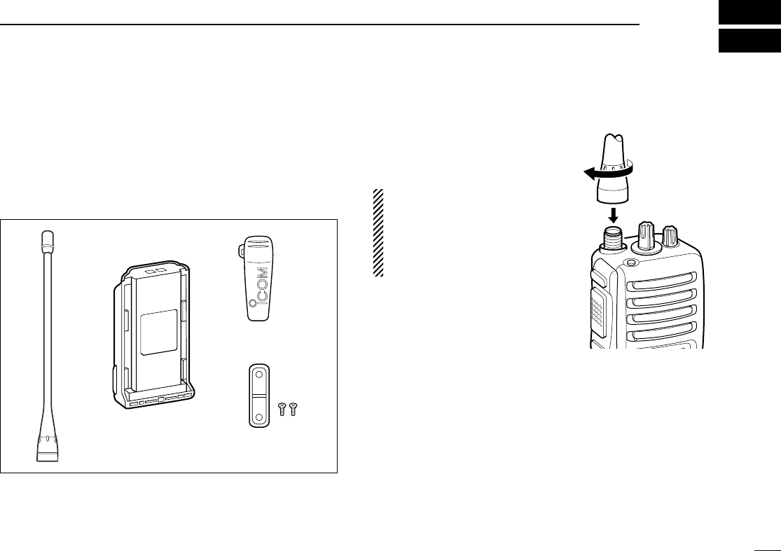
■Supplied accessories
The following accessories are supplied: Qty.
qFlexible antenna ……………………………………………1
wBattery pack …………………………………………………1
eBelt clip ………………………………………………………1
rJack cover (with screws) ………………………………1 set
■Accessory attachments
DFlexible antenna
Connect the supplied flexible
antenna to the antenna connector.
CAUTION!
• NEVER HOLD by the antenna
when carrying the transceiver.
• Transmitting without an an-
tenna may damage the trans-
ceiver.
qwe
r
!IC-F43TR.qxd 04.1.14 7:03 PM Page 1 (1,1)
2
1ACCESSORIES
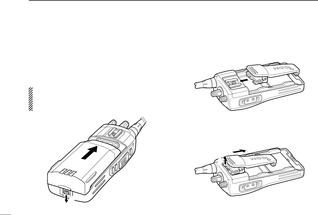
ïBattery pack
To attach the battery pack:
Slide the battery pack in the direction of the arrow (q), then
lock it with the battery release button.
• Slide the battery pack until the battery release button makes a ‘click’
sound.
To release the battery pack:
Push the battery release button in the direction of the arrow
(w) as shown below. The battery pack is then released.
NEVER release or attach the battery pack when the trans-
ceiver is wet or soiled. This may result water or dust get-
ting into the transceiver/battery pack and may result in the
transceiver being damaged.
DBelt clip
To attach the belt clip:
qRelease the battery pack if it is attached.
wSlide the belt clip in the direction of the arrow until the belt
clip is locked and makes a ‘click’ sound.
To detach the belt clip:
qRelease the battery pack if it is attached.
wLift the clip (q), and slide the belt clip in the direction of
the arrow (w).
q
w
q
w
!IC-F43TR.qxd 04.1.14 7:03 PM Page 2 (1,1)
3
1
ACCESSORIES
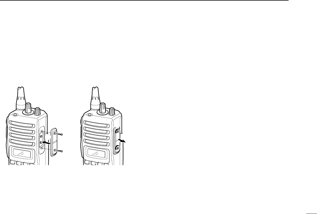
ïJack cover
Attach the jack cover when the optional speaker-microphone
is not used.
q
w
q
w
To attach the jack cover:
qAttach the jack cover on
the [SP MIC] connector.
wTighten the screws.
To detach the jack cover:
qUnscrew the screw with a
Phillips screwdriver.
wDetach the jack cover for
the speaker-microphone
connection.
!IC-F43TR.qxd 04.1.14 7:03 PM Page 3 (1,1)
4
2PANEL DESCRIPTION
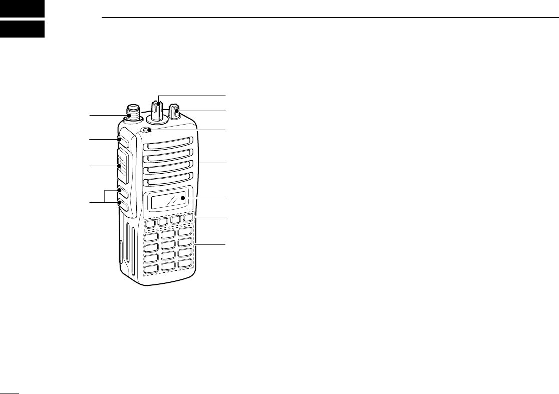
■Front panel
qROTARY SELECTOR
Selects the pre-programmed system channels or talk
groups (Max. 16) on the LTR/Passport system.
(Depending on the pre-setting)
wVOLUME CONTROL [VOL]
Turns power ON and adjusts the audio level.
eEMERGENCY KEY
Push to transmit the DTMF emergency call.
r[SP]/[MIC] JACK
Connect the optional speaker-microphone.
• Attach the jack cover when the optional speaker-microphone is
not used. (p. 3)
tFUNCTION DISPLAY
Displays a variety of information such as operating chan-
nel name, DTMF encode channel, selected function, etc.
yDEALER-PROGRAMMABLE KEYS [P0] to [P3]
Desired functions can be programmed independently by
your dealer.
u10-KEYPAD (Depending on version)
Used to enter DTMF encode channel, phone number, etc.
iUP/DOWN [∫∫]/[√√] KEYS
➥Push to select the operating channel.
➥Push to select the talk group on the LTR or Passport
system.
oPTT SWITCH [PTT]
Push and hold to transmit; release to receive.
!0 MONITOR KEY
Push to mute and release the CTCSS (DTCS) squelch
mute. Open squelch/deactivate mute while pushing this
key.
!1 ANTENNA CONNECTOR
Connects the supplied antenna.
it
r
q
e
u
y
w
!1
!0
o
10-keypad version
!IC-F43TR.qxd 04.1.14 7:03 PM Page 4 (1,1)
5
2
PANEL DESCRIPTION
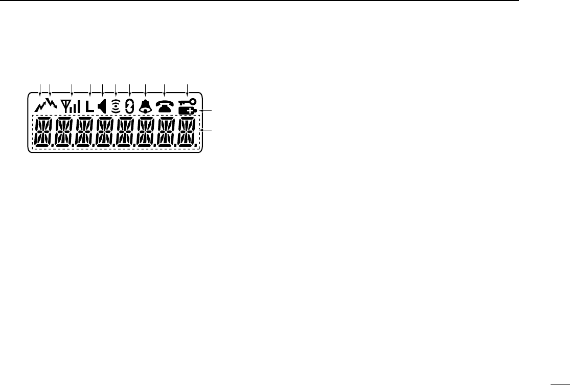
■Function display
qTRANSMIT INDICATOR
Appears while transmitting.
wBUSY INDICATOR
Appears while the channel is busy.
eSIGNAL STRENGTH INDICATOR
➥Indicates relative signal strength level.
➥Does not appear when the transceiver is out of the com-
munication area on the PassPort system.
rLOW POWER INDICATOR
Appears when low output power is selected.
• When the battery power decreases to a specified level, low
power is selected automatically.
tMONITOR INDICATOR
Appears when the monitor key is pushed.
yCOMPANDER INDICATOR
Appears when the compander function is activated.
uSCRAMBLER INDICATOR
Appears when the voice scrambler function is activated.
iBELL INDICATOR
➥Appears when the DTMF select call function is activat-
ed.
➥Blinks when the DTMF select call is received.
oPHONE INDICATOR
➥Appears on the system channel/talk group in which a
phone call is available.
➥Blinks when the phone call is received.
!0 KEY LOCK INDICATOR
Appears during the key lock function ON.
!1 BATTERY INDICATOR
Appears or blinks when the battery power decreases to a
specified level.
!2 ALPHANUMERIC DISPLAY
Displays an operating channel name, DTMF encode chan-
nel, etc.
q!0oiuytrew
!1
!2
!IC-F43TR.qxd 04.1.14 7:03 PM Page 5 (1,1)

6
2PANEL DESCRIPTION
■Programmable function keys
The following functions can be assigned to [P0], [P1], [P2],
[P3], [Emergency], [Monitor], [MM]* and [#]* programmable
function keys.
Consult your Icom dealer or system operator for details con-
cerning your transceivers programming.
If the programmable function names are bracketed in the fol-
lowing explanations, the specific key used to activate the
function depends on programming.
*Available on 10-keypad version only.
SEND DTMF KEY
Push to enter the DTMF encode channel selection mode.
SELECT CALL KEY
➥Push to turn the DTMF select call mute function ON.
➥Push and hold to turn the DTMF select call mute function
OFF.
PRIORITY KEY
Push to select the priority channel.
EMERGENCY KEY
Push to select the priority channel and automatically transmit
a DTMF emergency call code.
SCAN A KEY
➥This key’s operation depends on the Power ON Scan set-
ting.
When the power ON scan function is turned OFF;
Push to start and cancel scanning operation. In case of
transmission during scan, cancels scanning.
When the power ON scan function is turned ON;
Push to pause scanning. Scanning resumes after passing
a specified time period. In case of transmission during
scan, pauses scanning. Scanning resumes after passing
a specified time period specified.
➥Push and hold this key for 1 sec. to indicate the scan
group, then push to select the desired group.
SCAN B KEY
➥Push to start and cancel scanning operation. In case of
transmission during scan, pauses scanning. Scanning
resumes after passing a specified time period.
➥Push and hold this key for 1 sec. to indicate the scan
group, then push to select the desired group.
PRIORITY CHANNEL KEYS
➥Push to select Priority A or Priority B channel.
➥Push and hold [Prio A (Rewrite)] to rewrite the Prio A
channel.
!IC-F43TR.qxd 04.1.14 7:03 PM Page 6 (1,1)

7
2
PANEL DESCRIPTION
MONITOR KEY
Push to mute and release the CTCSS (DTCS) squelch mute.
Open squelch/deactivate mute while pushing this key.
NUISANCE DELETE KEY
Push to cancel the displayed channel from the scan list in the
talk group.
SCAN TYPE KEY
Push to toggle the scan type from Individual or Block.
SPEED DIAL KEY
Push to send the most recently transmitted DTMF code
selected with [Send DTMF].
TALK AROUND KEY
Turn the talk around function ON and OFF.
This function equalizes the transmit frequency to the receive
frequency for transceiver-to-transceiver communication.
WIDE/NARROW KEY
Push to toggle the IF passband width from “Wide” or “Narrow”
channel spacing for both transmission and reception tem-
porarily. Once the channel or bank has changed, the pass-
band width returns to the original setting.
TX POWER KEY
Push to toggle the transmit output power level from the inde-
pendent settings of each channel.
RE-DIAL KEY
Push to send the most recently transmitted DTMF code edit-
ed with 10-keypad.
RSSI KEY
Push to display the RSSI (Received Signal Strength Indicator)
level.
MODE DISPLAY TYPE KEY
Push to toggle the scan mode display type from Individual
and Block.
LOCK KEY
Push and hold for 2 sec. to turn the lock function ON and
OFF.
• User Password is prompted to turn the lock function OFF. See p. 9
for details of password input.
PHONE REQUEST KEY
Push to turn the phone call function ON and OFF in the oper-
ating channel.
!IC-F43TR.qxd 04.1.14 7:03 PM Page 7 (1,1)

8
2PANEL DESCRIPTION
ROAM REQUEST KEY
➥Push to return to the home site.
➥Push and hold to start roaming.
SITE LOCK KEY
Push to turn the Site Lock function ON and OFF.
This function inhibits automatic roaming, and can be useful
when the transceiver is out of the communication area such
as on a subway or in an elevator.
EMERGENCY SINGLE/REPEAT KEY
Push for the specified time period to select the emergency
channel and automatically send a DTMF emergency signal
once or repeatedly.
SCRAMBLER KEY
Push to toggle the scrambler function ON or OFF.
COMPANDER KEY
Push to turn the compander function ON and OFF.
The compander function reduces noise components from the
transmitted audio to provide clear communication.
USER SET MODE KEY
Push for 1 sec. to enter the User set mode.
The User set mode allows you to set seldom-changed set-
tings.
Push this key momentarily in the User set mode to select the
function, and push [CH Up] or [CH Down] to change the set-
ting.
SIREN KEY
Push to emit a siren. This function can be used for situations
such as a security alarm for example.
MODE SELECT KEY (available for Passport/LTR only)
Push to select the operating mode from System or Group.
!IC-F43TR.qxd 04.1.14 7:03 PM Page 8 (1,1)
9
3
BASIC OPERATION
■Turning power ON
qRotate [VOL] to turn the power ON.
wIf the transceiver is programmed for a start up passcode,
input the digit codes as directed by your dealer.
• The keys in the table below can be used for password input:
• The transceiver detects numbers in the same block as identical.
Therefore “01234” and “56789” are the same.
eWhen the “PASSWORD” indication does not clear after
inputting 4 digits, the input code number may be incorrect.
Turn the power off and start over in this case.
■Channel selection
Push [UP] or [DOWN], or rotate [ROTARY SELECTOR] to
select the desired system channel or talk group, in sequence.
• Up to 16 pre-programmed channels can be selected via [ROTARY
SELECTOR].
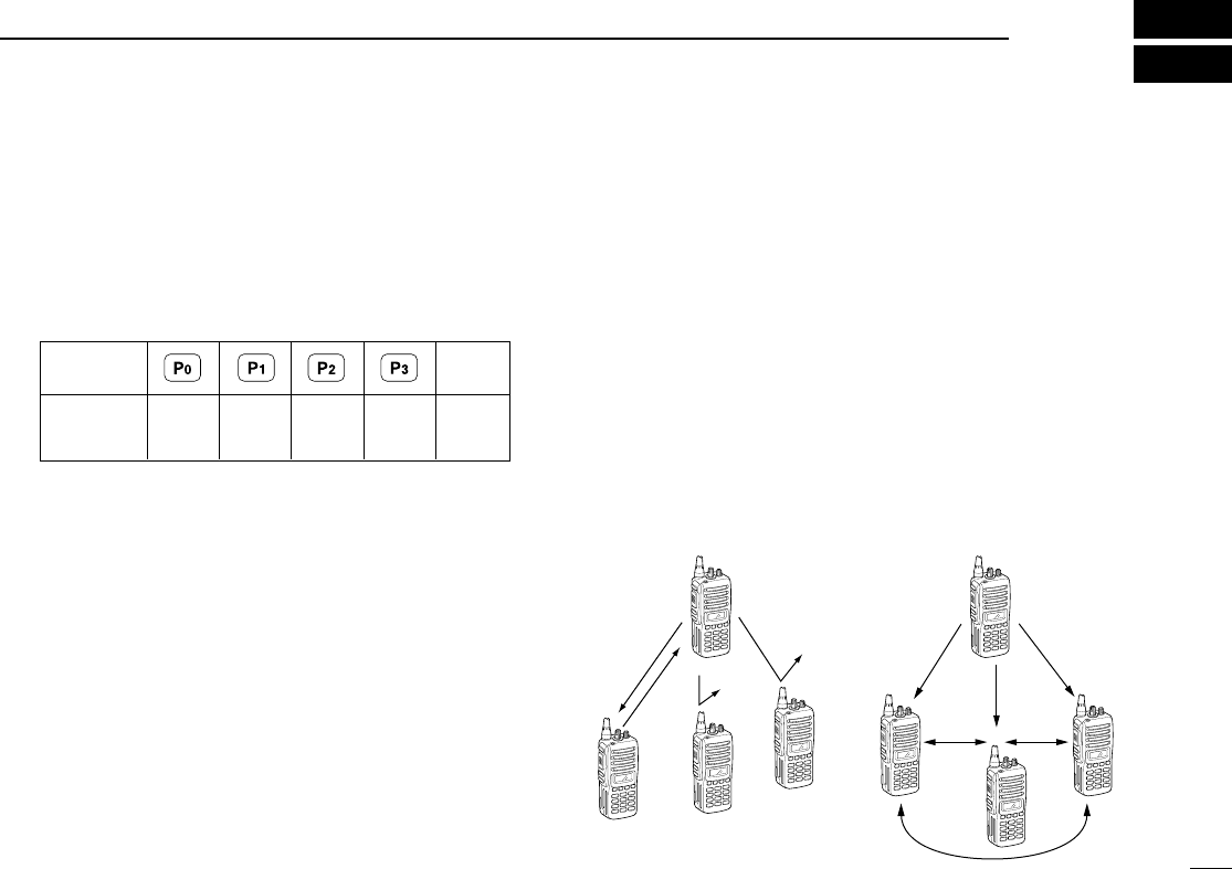
■Call procedure
When your system employs tone signalling (excluding
CTCSS and DTCS), the call procedure may be necessary
prior to voice transmission. The tone signalling employed may
be a selective calling system which allows you to call specific
station(s) only and prevent unwanted stations from contact-
ing you.
qSelect the desired DTMF encode channel according to
your System Operator’s instructions.
• This may not be necessary depending on programming.
• Refer to pgs. 11, 14, 16 for selection.
wPush the [PTT].
eAfter transmitting a DTMF code, the remainder of your
communication can be carried out in the normal fashion.
Selective calling Non-selective calling
KEY
NUMBER 0
5
4
9
3
8
2
7
1
6
UP
!IC-F43TR.qxd 04.1.14 7:03 PM Page 9 (1,1)
10
4PASSPORT OPERATION
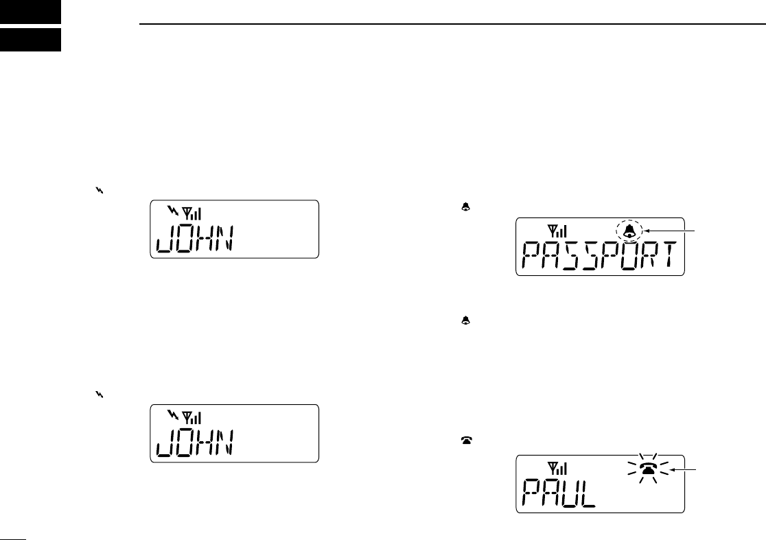
■Receiving a call
DGroup call
qPush [UP] or [DOWN], or rotate [ROTARY SELECTOR]
to select the Passport system channel or talk group.
wWhen a call is received;
•“ ” and the calling station name/ID appear.
ePush and hold [PTT], then speak into the microphone at
a normal voice level.
rRelease [PTT] to return to receive.
DIndividual call
qPush [UP] or [DOWN], or rotate [ROTARY SELECTOR]
to select the Passport system channel or talk group.
wWhen a call is received;
•“ ” and the calling station name/ID appear.
ePush and hold [PTT], then speak into the microphone at
a normal voice level.
rRelease [PTT] to return to receive.
tTo finish the conversation, push [DOWN] to send the
“Clear Down” signal.
DSelective call (DTMF call)
—Optional UT-108 is required—
qPush [UP] or [DOWN], or rotate [ROTARY SELECTOR]
to select the Passport system channel or talk group.
wPush [Select call] to mute the channel.
•“ ” appears.
eWhen receiving a call, the calling station name appears
and a beep is emitted. Then the mute is released.
•“ ” disappears.
DPhone call
qPush [UP] or [DOWN], or rotate [ROTARY SELECTOR]
to select the Passport system channel or talk group.
wWhen a phone call is received (transceiver rings), push
and hold [PTT], then speak into the microphone at a nor-
mal voice level.
•“ ” blinks and calling station name/ID appears for 1 sec.
eRelease [PTT] to return to receive.
rPush [#] while pushing [PTT] to finish the communication.
Blinks
Appears
!IC-F43TR.qxd 04.1.14 7:03 PM Page 10 (1,1)

11
4
PASSPORT OPERATION
■Transmitting a call
DGroup call
qPush [UP] or [DOWN], or rotate [ROTARY SELECTOR]
to select the Passport system channel or talk group in
which the group ID is pre-programmed.
wWhile pushing and holding [PTT], speak into the micro-
phone at a normal voice level after a beep is emitted.
• If an error beep is emitted, release [PTT]. After a while, repeat
step wagain.
• The beep can be turned OFF in User set mode.
•When the transceiver is out of the communication area, “”
disappears, and “NO SVC” message appears.
DIndividual call
qPush [UP] or [DOWN], or rotate [ROTARY SELECTOR]
to select the Passport system channel or talk group in
which the MID (Mobile ID) is pre-programmed.
wWhile pushing and holding [PTT], speak into the micro-
phone at a normal voice level after a beep is emitted.
• If an error beep is emitted, release [PTT]. After a while, repeat
step wagain.
• The beep can be turned OFF in User set mode.
•When the transceiver is out of the communication area, “”
disappears, and “NO SVC” message appears.
eTo finish the conversation, push [DOWN] to send the
“Clear Down” signal.
DSelective call (DTMF call)
—Optional UT-108 is required—
qPush [UP] or [DOWN], or rotate [ROTARY SELECTOR]
to select the Passport system channel or talk group.
wPush [Send DTMF]— a DTMF encode channel appears.
ePush [UP] or [DOWN] to select the desired DTMF encode
channel.
rPush [PTT] to transmit the selected DTMF code in the
selected DTMF channel.
• Push [P0] to cancel the DTMF transmission.
DPhone call (Available for 10-keypad version only)
qPush [UP] or [DOWN], or rotate [ROTARY SELECTOR]
to select the Passport system channel or talk group.
wPush [Phone request] to enable the phone call.
•“ ” appears.
ePush [PTT] to connect the phone line.
•The proceed tone is emitted after connection to the phone line.
rWhile pushing and holding [PTT], enter the phone number
via the 10-keypad to make the call. Then release [PTT].
tPush [PTT] to transmit; release to receive.
yPush [#] while pushing [PTT] to finish the communication.
Appears
!IC-F43TR.qxd 04.1.14 7:03 PM Page 11 (1,1)

12
4PASSPORT OPERATION
■Other functions
DManual roaming start function
If the transceiver has [Roam Request] assigned to it, you
can start roaming manually to search for another site.
qPush [UP] or [DOWN], or rotate [ROTARY SELECTOR]
to select the Passport system channel or talk group.
wPush and hold [Roam Request] to start roaming.
•“ROAMSITE” is displayed.
•When “INVALID” is displayed, the home repeater may not have a
neighbour site. After a while, repeat step w.
ePush [Roam Request] to cancel roaming.
DSite lock function
If the transceiver has [Site Lock] assigned to it, automatic
roaming can be inhibited. This function is useful when the
transceiver is out of the communication area such as on a
subway or in an elevator.
qPush [UP] or [DOWN], or rotate [ROTARY SELECTOR]
to select the Passport system channel or talk group.
wPush [Site Lock] to turn the site lock function ON and
OFF.
•“SITELOCK” is displayed.
!IC-F43TR.qxd 04.1.14 7:03 PM Page 12 (1,1)
13
5
LTR OPERATION
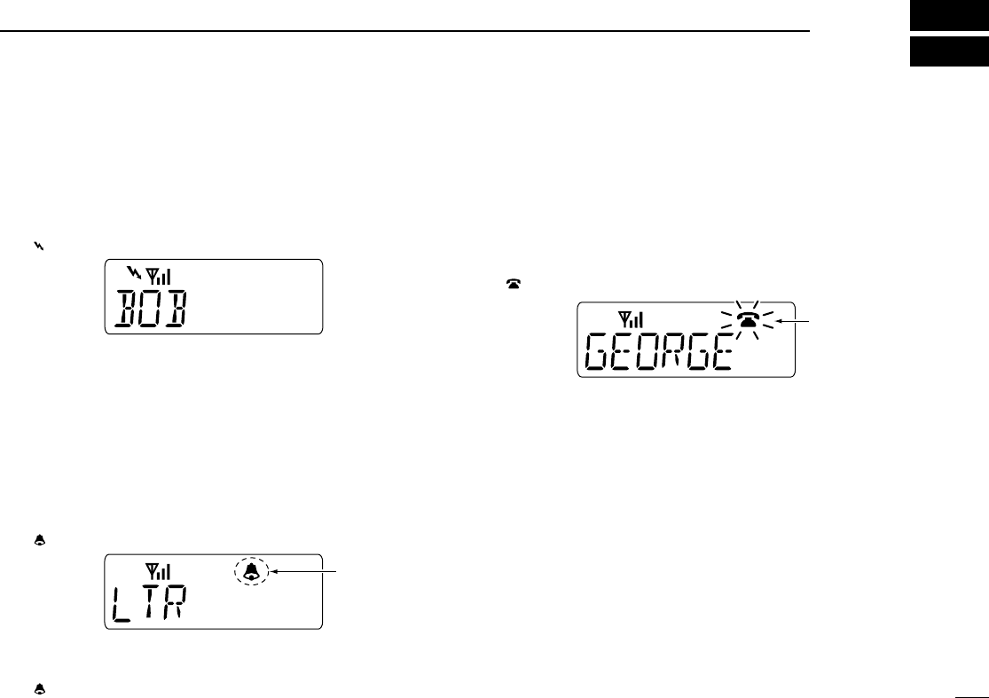
■Receiving a call
DGroup call
qPush [UP] or [DOWN], or rotate [ROTARY SELECTOR]
to select the LTR system channel or talk group.
wWhen a call is received;
•“ ” and the calling station name/ID appear.
ePush and hold [PTT], then speak into the microphone at
a normal voice level.
rRelease [PTT] to return to receive.
DSelective call (DTMF call)
—Optional UT-108 is required—
qPush [UP] or [DOWN], or rotate [ROTARY SELECTOR]
to select the LTR system channel or talk group.
wPush [Select call] to mute the channel.
•“ ” appears.
eWhen receiving a call, the calling station name appears
and a beep is emitted. Then the mute is released.
•“ ” disappears.
DPhone call
qPush [UP] or [DOWN], or rotate [ROTARY SELECTOR]
to select the LTR system channel or talk group.
wWhen a phone call is received (transceiver rings), push
and hold [PTT], then speak into the microphone at a nor-
mal voice level.
•“ ” blinks and calling station name/ID appears for 1 sec.
eRelease [PTT] to return to receive.
rPush [#] while pushing [PTT] to finish the communication.
Blinks
Appears
!IC-F43TR.qxd 04.1.14 7:03 PM Page 13 (1,1)

14
5LTR OPERATION
■Transmitting a call
DGroup call
qPush [UP] or [DOWN], or rotate [ROTARY SELECTOR]
to select the LTR system channel or talk group.
wWhile pushing and holding [PTT], speak into the micro-
phone at a normal voice level after a beep is emitted.
• If an error beep is emitted, release [PTT]. After a while, repeat
step w.
• The beep can be turned OFF in User set mode.
DSelective call (DTMF call)
—Optional UT-108 is required—
qPush [UP] or [DOWN], or rotate [ROTARY SELECTOR]
to select the LTR system channel or talk group.
wPush [Send DTMF]— a DTMF encode channel appears.
ePush [UP] or [DOWN] to select the desired DTMF encode
channel.
rPush [PTT] to transmit the selected DTMF code in the
selected DTMF channel.
• Push [Send DTMF] to cancel the DTMF transmission.
!IC-F43TR.qxd 04.1.14 7:03 PM Page 14 (1,1)

15
6
CONVENTIONAL OPERATION
■Receiving and transmitting
NOTE: Transmitting without an antenna may damage the
transceiver. See p. 1 for antenna attachment.
Receiving:
qRotate [VOL] to turn the power ON.
wPush [UP] or [DOWN], or rotate [ROTARY SELECTOR]
to select the conventional system channel, in sequence.
eWhen receiving a call, adjust the audio output level to a
comfortable listening level.
Transmitting:
Wait for the channel to become clear to avoid interference.
qWhile pushing and holding [PTT], speak into the micro-
phone at a normal voice level.
wRelease [PTT] to return to receive.
IMPORTANT: To maximize the readability of your signal;
1. Pause briefly after pushing [PTT].
2. Hold the microphone 5 to 10 cm (2 to 4 inches) from
your mouth, then speak into the microphone at a normal
voice level.
DTransmitting notes
• Transmit inhibit function
The transceiver has several inhibit functions which restrict
transmission under the following conditions:
- Channel is busy.
- Un-matched (or matched) CTCSS is received.
- The selected channel is a ‘receive only’channel.
• Time-out timer
After continuous transmission for the pre-programmed time
period, the time-out timer is activated, causing the transceiv-
er to stop transmitting.
• Penalty timer
Once the time-out timer is activated, transmission is further
inhibited for a period determined by the penalty timer.
!IC-F43TR.qxd 04.1.14 7:03 PM Page 15 (1,1)

16
6CONVENTIONAL OPERATION
DDTMF receiving and transmitting
—Optional UT-108 is required—
If the transceiver has [Send DTMF] assigned to it, a DTMF
encode channel is displayed when pushed, and assigned
DTMF encode channels can be selected via [UP] or [DOWN].
Receiving:
qPush [UP] or [DOWN], or rotate [ROTARY SELECTOR]
to select the conventional system channel, in sequence.
wPush [Select call] to mute the channel. (“” appears)
eWhen receiving a call, a beep is emitted and mute is
released. (“” disappears)
Transmitting:
qPush [UP] or [DOWN], or rotate [ROTARY SELECTOR]
to select the conventional system channel, in sequence.
wPush [Send DTMF]— a DTMF encode channel appears.
ePush [UP] or [DOWN] to select the desired DTMF encode
channel.
rPush [PTT] to transmit the selected DTMF code in the
selected DTMF channel.
• Push [P0] to cancel the DTMF transmission.
■User set mode
User set mode is accessed with [User Set Mode] and allows
you to set seldom-changed settings. In this case you can
“customize” the transceiver operation to suit your preferences
and operating style.
Entering the user set mode:
qPush and hold [User Set Mode] to enter user set mode.
Push [User Set Mode] momentarily to select the item.
Then push [UP] or [DOWN] to set the desired level/condi-
tion.
Available set mode functions:
•Backlight : ON, Auto or OFF
•Ringer : ON or OFF
•Beep : ON or OFF
•SQL Level : 0 to 255
•Mic Gain : 1 to 5
•Battery Voltage : ON or OFF
•System Information : ON or OFF
•Run-Time : The transceiver’s running time is
displayed.
wPush and hold [User Set Mode] to exit user set mode.
!IC-F43TR.qxd 04.1.14 7:03 PM Page 16 (1,1)

17
6
CONVENTIONAL OPERATION
■Emergency transmission
When [Emergency], [Emergency Single] or [Emergency
Repeat] is pushed, an emergency signal is automatically
transmitted for the specified time period.
When [Emergency] is pushed, the DTMF emergency signal
is transmitted on the priority channel.
When [Emergency Single] or [Emergency Repeat] is
pushed for the specified time period, the DTMF emergency
signal is transmitted once or repeatedly on the emergency
channel. However, when no emergency channel is specified,
the signal is transmitted on the previously selected channel.
■Scrambler function
The voice scrambler function provides private communication
between stations. The frequency inversion type is equipped
to all versions, moreover, the optional Rolling or Non-rolling
type can be available.
qPush [Scrambler] to turn the scrambler function ON.
• “” appears.
wPush [Scrambler] again to turn the scrambler function
OFF.
• “” disappears.
■Stun function
When the specified code, set as a stun code, is received, the
stun function will be activated. When the stun code is
received, “STUNNED” appears on the display and the trans-
ceiver cannot be used. To use the transceiver, the stun
release code must be received.
Also, if the transceiver’s running time exceeds the preset run-
ning time limit, the transceiver cannot be used. To use the
transceiver, extend the running time limit or turn the Run Time
Limit function OFF using the CS-F43TR
CLONING SOFTWARE
.
■Man Down transmission
When the optional UT-113
MAN DOWN UNIT
is installed, the
Man Down function can be used. The Man Down function
transmits a man down emergency call after the specified time
period has passed with the transceiver in a horizontal posi-
tion.
!IC-F43TR.qxd 04.1.14 7:03 PM Page 17 (1,1)
18
7OPTIONAL UNIT INSTALLATION
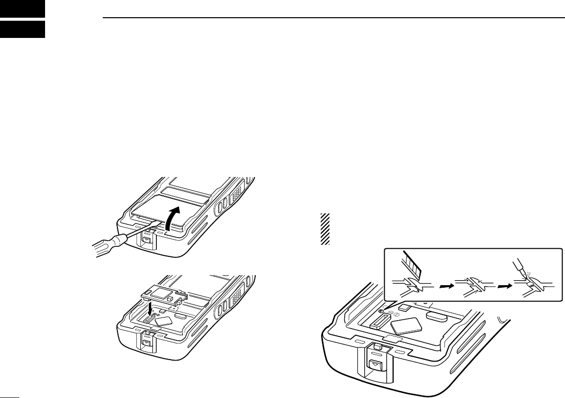
■UT-113 installation
Install the optional UT-113
MAN DOWN UNIT
as follows:
qRotate [VOL] to turn the power OFF, and remove the bat-
tery pack. (p. 2)
wRemove the unit cover.
NOTE: Use a flat head screw driver or a similar flat instrument,
and insert into the hollow of the chassis, then lift and take away
the unit cover. (The removed cover cannot be used again.)
eInstall the unit as shown below.
rReplace the unit cover and the battery pack, then rotate
[VOL] to turn the power ON.
■UT-108 installation
Install the optional UT-108
DTMF DECODER UNIT
as follows:
qRotate [VOL] to turn the power OFF, and remove the bat-
tery pack. (p. 2)
wRemove the unit cover as shown at left.
eCut and solder the pattern on the PCB at the RX AF cir-
cuit as shown below.
rInstall the UT-108
DTMF DECODER UNIT
the same way as
described in the optional UT-113 installation as shown at left.
tReplace the unit cover and the battery pack, then rotate
[VOL] to turn the power ON.
NOTE: Be sure to un-solder A and B, and re-solder B and
C, otherwise no AF output is available when you remove
the DTMF decoder unit.
A
B
C
!IC-F43TR.qxd 04.1.14 7:03 PM Page 18 (1,1)
19
7
OPTIONAL UNIT INSTALLATION
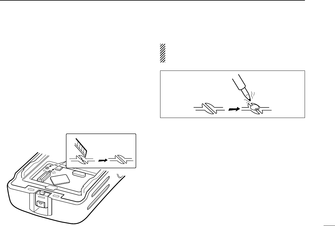
■UT-109 and UT-110 installation
Install the optional UT-109/UT-110
SCRAMBLER UNITS
as fol-
lows:
qRotate [VOL] to turn the power OFF, and remove the bat-
tery pack. (p. 2)
wRemove the unit cover as shown on p. 18 (UT-113 instal-
lation).
eCut the pattern on the PCB at the TX mic circuit (MIC) and
RX AF circuit (DISC) as shown below.
rInstall the UT-109/UT-110
SCRAMBLER UNITS
as described
in the optional UT-113 installation (p. 18).
tReplace the unit cover and the battery pack, then rotate
[VOL] to turn the power ON.
NOTE: Be sure to re-solder the disconnected points at left,
otherwise no TX modulation or AF output is available when
you remove the scrambler units.
!IC-F43TR.qxd 04.1.14 7:03 PM Page 19 (1,1)

20
8BATTERY CHARGING
■Battery charging
Prior to using the transceiver for the first time, the battery
pack must be fully charged for optimum life and operation.
CAUTION: To avoid damage to the transceiver, turn the
power OFF while charging.
• Recommended temperature range for charging:
+10°C to +40°C (+50°F to +104°F)
• Use the specified chargers (BC-119N and BC-121N).
NEVER use another manufacture’s charger.
• Use the specified AC adapter. NEVER use another manu-
facture’s adapter.
■Battery caution
CAUTION! NEVER insert battery pack/transceiver
(with the battery pack attached) in a wet or soiled condition
into the charger. This may result in corrosion of the charger
terminals or damage to the charger. The charger is not wa-
terproof and water can easily get into it.
NEVER incinerate used battery packs. Internal battery gas
may cause an explosion.
NEVER immerse the battery pack in water. If the battery
pack becomes wet, be sure to wipe it dry BEFORE attaching
it to the transceiver.
NEVER short the terminals of the battery pack. Also, cur-
rent may flow into nearby metal objects, such as a necklace,
etc. Therefore, be careful when carrying with, or placing near
metal objects, carrying in handbags, etc.
If your battery pack seems to have no capacity even after
being charged, completely discharge it by leaving the power
ON overnight. Then, fully charge the battery pack again. If the
batteries still do not retain a charge (or very little), new bat-
tery pack must be purchased.
!IC-F43TR.qxd 04.1.14 7:03 PM Page 20 (1,1)
21
8
BATTERY CHARGING
■Optional battery chargers
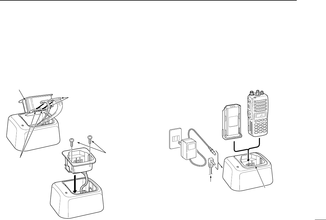
ïAD-106 installation
qInstall the AD-106 desktop charger adapter into the holder
space of the BC-119N/121N.
wConnect the plugs of the BC-119N/121N to the AD-106
desktop charger adapter with the connector, then install
the adapter into the charger with the supplied screws.
ïRapid charging with the BC-119N+AD-106
The optional BC-119N provides rapid charging of battery
packs. The following are additionally required.
• AD-106 charger adapter
• An AC adapter (may be supplied with BC-119N depending
on version).
AD-106 charger
adapter is installed
in BC-119N.
AC adapter
(Not supplied with
some versions.)
Optional OPC-515L (for 13.8 V
power source) or CP-17L (for 12
V cigarette lighter socket) can be
used instead of the AC adapter.
IC-F43TR
BP-232
Screws supplied
with the charger
adapter
Desktop charger adapter
Connectors
Plugs
!IC-F43TR.qxd 04.1.14 7:03 PM Page 21 (1,1)
22
8BATTERY CHARGING
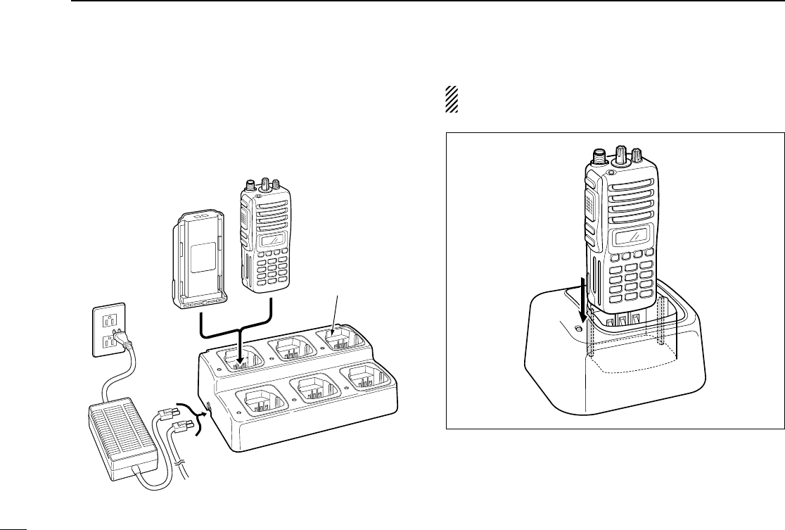
ïRapid charging with the BC-121N+AD-106
The optional BC-121N allows up to 6 battery packs to be
charged simultaneously. The following are additionally
required.
• Six AD-106 charger adapters
• An AC adapter (BC-124)
IMPORTANT: Ensure the sides of the battery pack are cor-
rectly aligned with the charger groves.
AD-106 charger
adapters are installed
in each slot.
DC power cable (OPC-656)
(Connect with the DC power supply;
13.8 V/at least 7 A)
AC adapter
(Purchase
separately)
IC-F43TR
BP-232
!IC-F43TR.qxd 04.1.14 7:03 PM Page 22 (1,1)
23
9
SWIVEL BELT CLIP
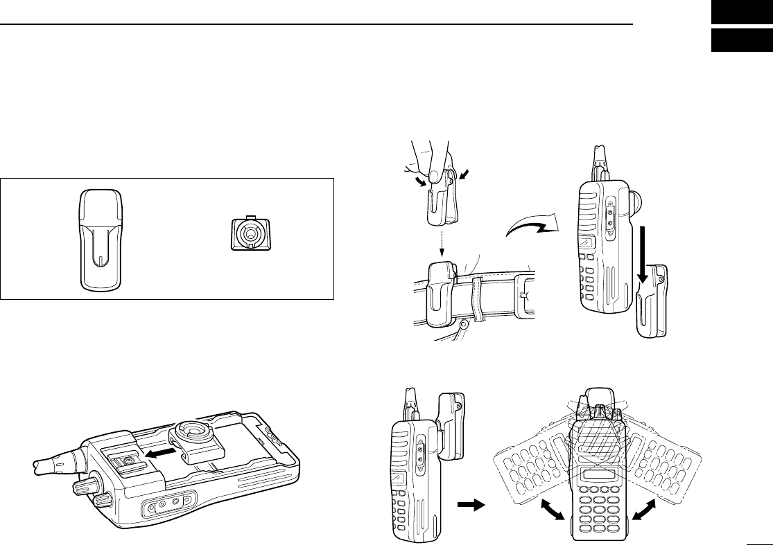
■MB-93 contents
Qty.
qBelt clip ……………………………………………………… 1
wBase clip …………………………………………………… 1
■To attach
qRelease the battery pack if it is attached. (p. 1)
wSlide the base clip in the direction of the arrow.
eClip the belt clip to a part of your belt. And insert the trans-
ceiver into the belt clip until the base clip inserted fully into
the groove.
rOnce the transceiver is locked in place, it swivels as illus-
trated below.
q w
!IC-F43TR.qxd 04.1.14 7:03 PM Page 23 (1,1)
24
9SWIVEL BELT CLIP
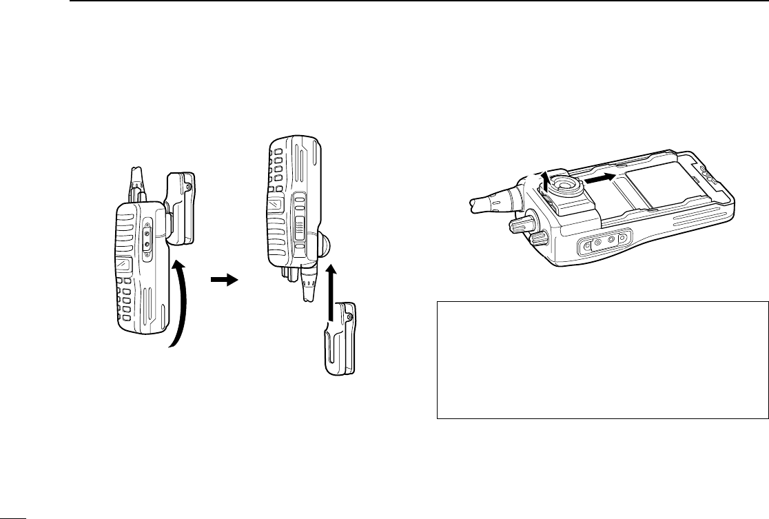
■To detach
qTurn the transceiver upside down in the direction of the
arrow and pull out from the belt clip.
wRelease the battery pack if it is attached. (p. 1)
ePinch the clip (q), and slide the base clip in the direction
of the arrow (w).
RRCAUTION!
HOLD THE TRANSCEIVER TIGHTLY, WHEN HANGING
OR DETACHING THE TRANSCEIVER FROM THE BELT
CLIP.
Otherwise the transceiver may not be attached to the hold-
er or swivel properly if the transceiver is accidentally
dropped and the base clip is scratched or damaged.
qw
!IC-F43TR.qxd 04.1.14 7:03 PM Page 24 (1,1)

25
10
OPTIONS
DBATTERY PACK
•BP-230 Li-Ion
BATTERY PACK
7.4 V/800 mAh Li-Ion battery pack, allows more than 4 hours oper-
ation.
•BP-231 Li-Ion
BATTERY PACK
7.4 V/1150 mAh Li-Ion battery pack, allows more than 6 hours oper-
ation.
•BP-232 Li-Ion
BATTERY PACK
7.4 V/2000 mAh Li-Ion battery pack, allows more than 11 hours
operation. The same as supplied with the transceiver.
DCHARGERS
•BC-119N
DESKTOP CHARGER
+ AD-106
CHARGER ADAPTER
+ BC-145
AC ADAPTER
For rapid charging of battery packs. An AC adapter is supplied with
the charger depending on versions. Charging time: approx. 3 hours
when BP-232 is attached.
•BC-121N
MULTI
-
CHARGER
+ AD-106
CHARGER ADAPTER
(6 pcs.)
+ BC-124
AC ADAPTER
For rapid charging of up to 6 battery packs (six AD-106’s are
required) simultaneously. An AC adapter should be purchased sep-
arately. Charging time: approx. 3 hours when BP-232 is attached.
DBELT CLIPS
•MB-94
BELT CLIP
Exclusive alligator-type belt clip. The same as supplied with the
transceiver.
•MB-93
SWIVEL BELT CLIP
•MB-96*/96F
LEATHER BELT HANGER
*MB-93’s base clip is required.
DOPTIONAL UNITS
•UT-108
DTMF DECODER UNIT
Provides pager and code squelch capabilities.
• UT-109 (#02)/UT-110 (#02)
SCRAMBLER UNITS
Non-rolling type (UT-109)/Rolling type (UT-110) voice scrambler unit
provides higher communication security.
• UT-113
MAN DOWN UNIT
Provides a measure of safety when working in a hazardous envi-
ronment, etc.
DDC CABLES
•CP-17L
CIGARETTE LIGHTER CABLE
Allows charging of the battery pack through a 12 V cigarette lighter
socket. (For BC-119N)
•OPC-515L/OPC-656
DC POWER CABLES
Allows charging of the battery pack using a 13.8 V power source
instead of the AC adapter.
OPC-515L: For BC-119N
OPC-656 : For BC-121N
DOTHER OPTIONS
•SP-13
EARPHONE
Provides clear receive audio in noisy environment.
•HM-46L/HM-131L
SPEAKER
-
MICROPHONES
Combination speaker-microphone that provides convenient opera-
tion while hanging the transceiver from your belt.
•HS-94/HS-95/HS-97
HEADSET
+ VS-1L
VOX
/
PTT CASE
HS-94: Ear-piece type
HS-95: Neck-arm type
HS-97: Throat microphone
VS-1L: VOX/PTT switch box for hands-free operation, etc.
•FA-SC73US
STUBBY ANTENNA
Shorter UHF antenna. Frequency range: 450–490 MHz
!IC-F43TR.qxd 04.1.14 7:03 PM Page 25 (1,1)

26
11 SAFETY TRAINING INFORMATION
Your Icom radio generates RF electromagnetic
energy during transmit mode. This radio is
designed for and classified as “Occupational Use
Only”, meaning it must be used only during the
course of employment by individuals aware of the
hazards, and the ways to minimize such hazards.
This radio is NOT intended for use by the “General Population” in
an uncontrolled environment.
This radio has been tested and complies with the FCC RF expo-
sure limits for “Occupational Use Only”. In addition, your Icom
radio complies with the following Standards and Guidelines with
regard to RF energy and electromagnetic energy levels and eval-
uation of such levels for exposure to humans:
• FCC OET Bulletin 65 Edition 97-01 Supplement C,
Evaluating Compliance with FCC Guidelines for Human
Exposure to Radio Frequency Electromagnetic Fields.
• American National Standards Institute (C95.1-1992), IEEE
Standard for Safety Levels with Respect to Human Exposure
to Radio Frequency Electromagnetic Fields, 3 kHz to 300
GHz.
• American National Standards Institute (C95.3-1992), IEEE
Recommended Practice for the Measurement of Potentially
Hazardous Electromagnetic Fields– RF and Microwave.
• The following accessories are authorized for use with this
product. Use of accessories other than those specified may
result in RF exposure levels exceeding the FCC require-
ments for wireless RF exposure.; Belt Clip (MB-94),
Rechargeable Li-Ion Battery Pack (BP-232) and Speaker-
microphone (HM-131L).
To ensure that your expose to RF electromag-
netic energy is within the FCC allowable limits
for occupational use, always adhere to the fol-
lowing guidelines:
• DO NOT operate the radio without a proper antenna
attached, as this may damaged the radio and may also
cause you to exceed FCC RF exposure limits. A proper
antenna is the antenna supplied with this radio by the manu-
facturer or antenna specifically authorized by the manufac-
turer for use with this radio.
• DO NOT transmit for more than 50% of total radio use time
(“50% duty cycle”). Transmitting more than 50% of the time
can cause FCC RF exposure compliance requirements to be
exceeded. The radio is transmitting when the “” (TX indi-
cator) lights. You can cause the radio to transmit by pressing
the “PTT” switch.
• ALWAYS keep the antenna at least 2.5 cm (1 inch) away
from the body when transmitting and only use the Icom belt-
clips listed on page 25 when attaching the radio to your belt,
etc., to ensure FCC RF exposure compliance requirements
are not exceeded. To provide the recipients of your transmis-
sion the best sound quality, hold the antenna at least 5 cm
(2 inches) from your mouth, and slightly off to one side.
The information listed above provides the user with the informa-
tion needed to make him or her aware of RF exposure, and what
to do to assure that this radio operates with the FCC RF expo-
sure limits of this radio.
CAUTION
WARNING
!IC-F43TR.qxd 04.1.14 7:03 PM Page 26 (1,1)

27
11
SAFETY TRAINING INFORMATION
Electromagnetic Interference/Compatibility
During transmissions, your Icom radio generates RF energy that
can possibly cause interference with other devices or systems.
To avoid such interference, turn off the radio in areas where signs
are posted to do so. DO NOT operate the transmitter in areas
that are sensitive to electromagnetic radiation such as hospitals,
aircraft, and blasting sites.
Occupational/Controlled Use
The radio transmitter is used in situations in which persons are
exposed as consequence of their employment provided those
persons are fully aware of the potential for exposure and can
exercise control over their exposure.
!IC-F43TR.qxd 04.1.14 7:03 PM Page 27 (1,1)

1-1-32 Kamiminami, Hirano-ku, Osaka 547-0003, Japan
A-6344H-1EX
Printed in Japan
© 2004 Icom Inc.
!IC-F43TR.qxd 04.1.14 7:03 PM Page Z (1,1)