ICOM orporated 272102 UHF-FM Trunked Radio Transceiver User Manual IC F43TR Instruction Manual
ICOM Incorporated UHF-FM Trunked Radio Transceiver IC F43TR Instruction Manual
UserManual.wiki
>
ICOM orporated
>
272102 User Manual
>
Updated User Manual
Contents
1.
Manual
2.
Updated User Manual
Updated User Manual
Navigation menu
Upload a User Manual
Namespaces
Wiki Guide
HTML
PDF
Info
Views
User Manual
Discussion / Help
Navigation
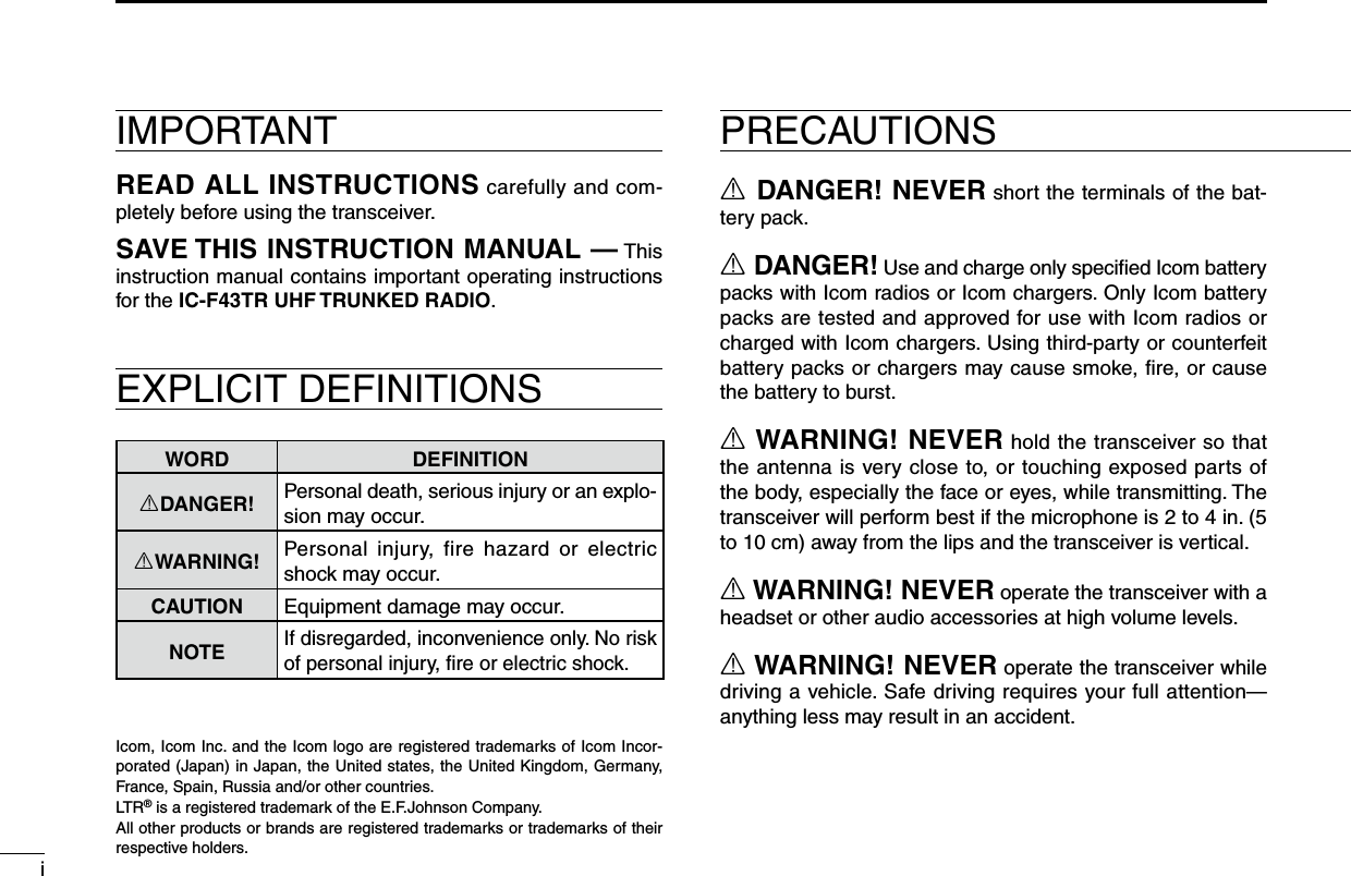
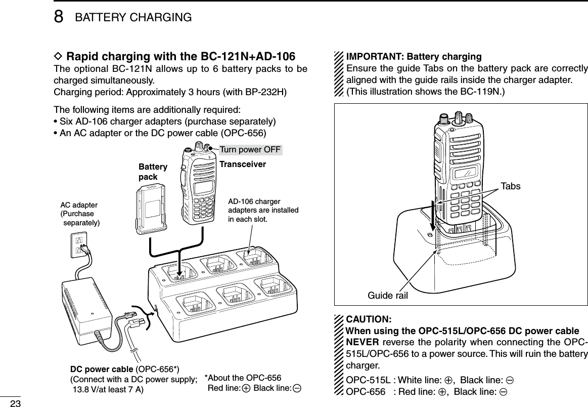
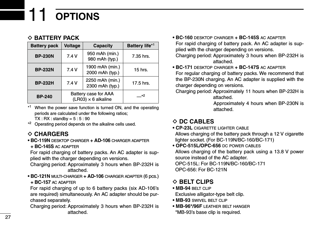
![21ACCESSORIESD Belt clipTo attach the belt clip:q Remove the battery pack if it is attached.w Slide the belt clip in the direction of the arrow until the belt clipislockedandmakesa‘click’sound.To detach the belt clip:q Remove the battery pack if it is attached.w Lift the clip (q), and slide the belt clip in the direction of the arrow (w).D Jack cover Attach the jack cover when the optional speaker-microphone is not used.qwTo attach the jack cover:q Attach the jack cover on the [SP MIC] connector.w Tighten the screws.To detach the jack cover:q Remove the screw with a Phillips screwdriver.w Detach the jack cover for the speaker-microphone connection.qwqw](https://usermanual.wiki/ICOM-orporated/272102.Updated-User-Manual/User-Guide-1870944-Page-7.png)
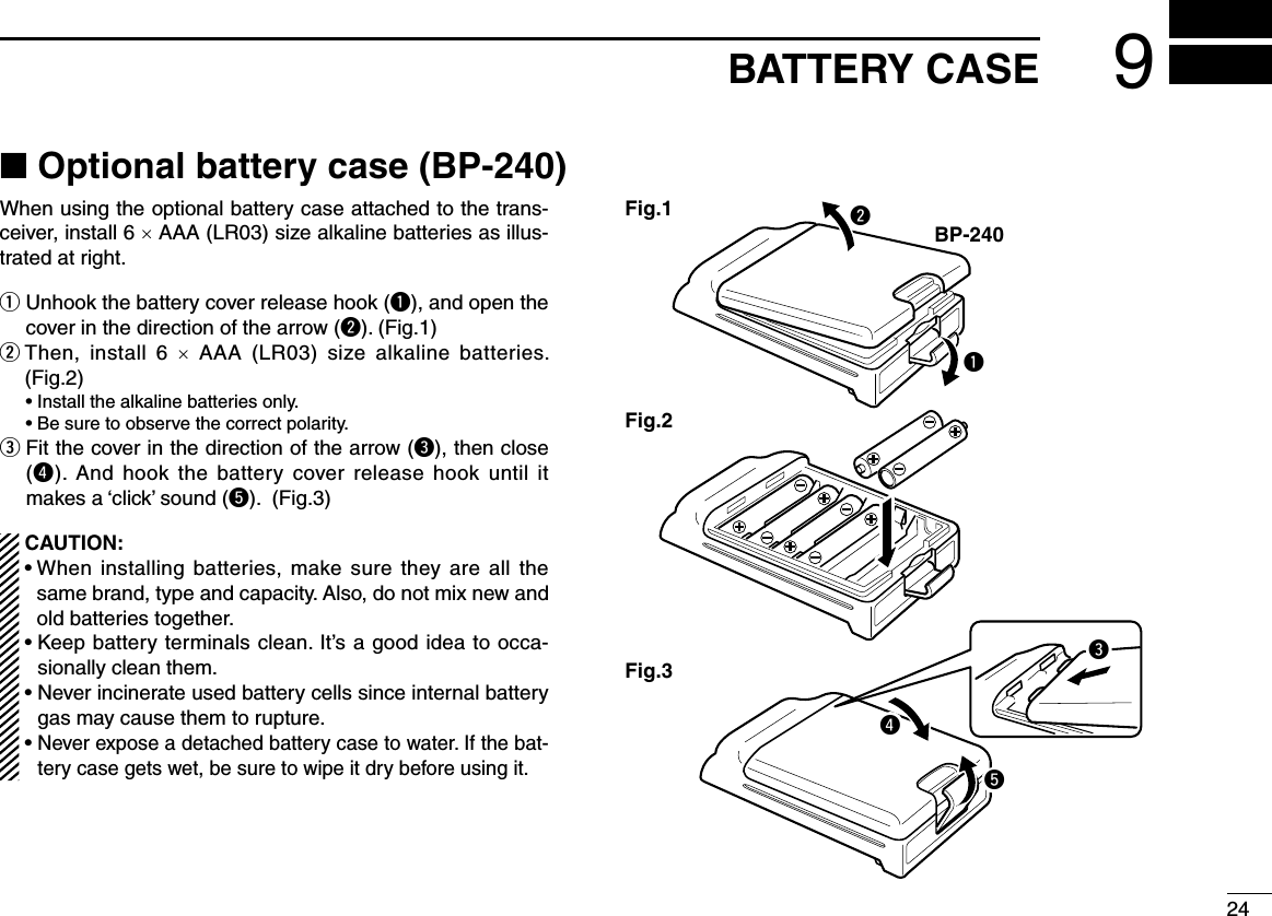
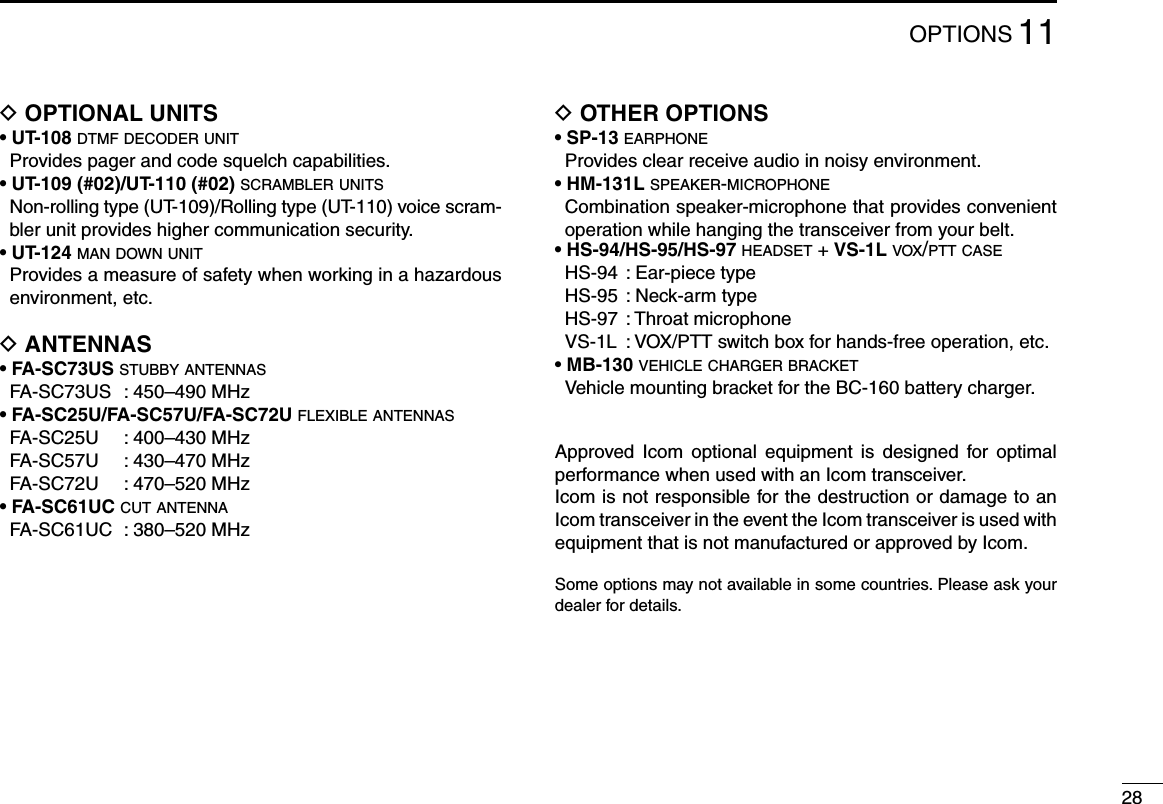
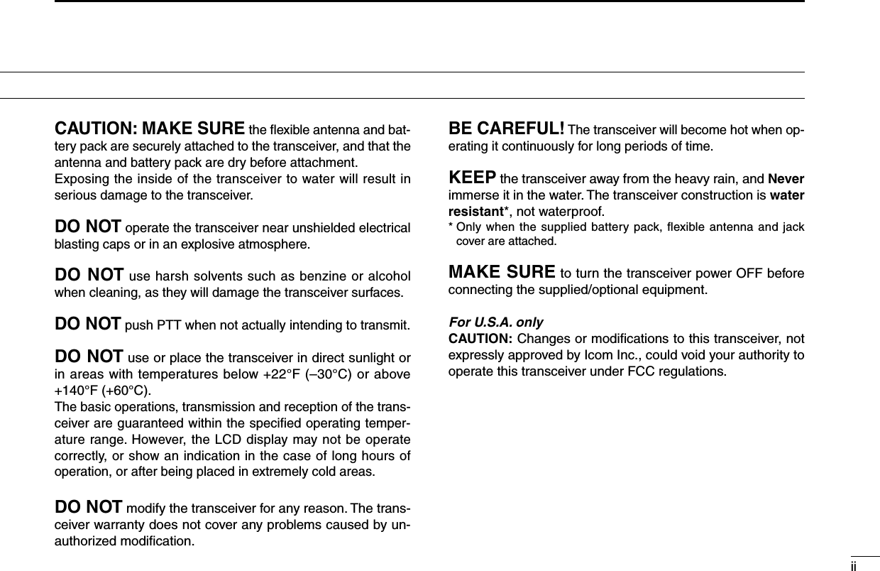
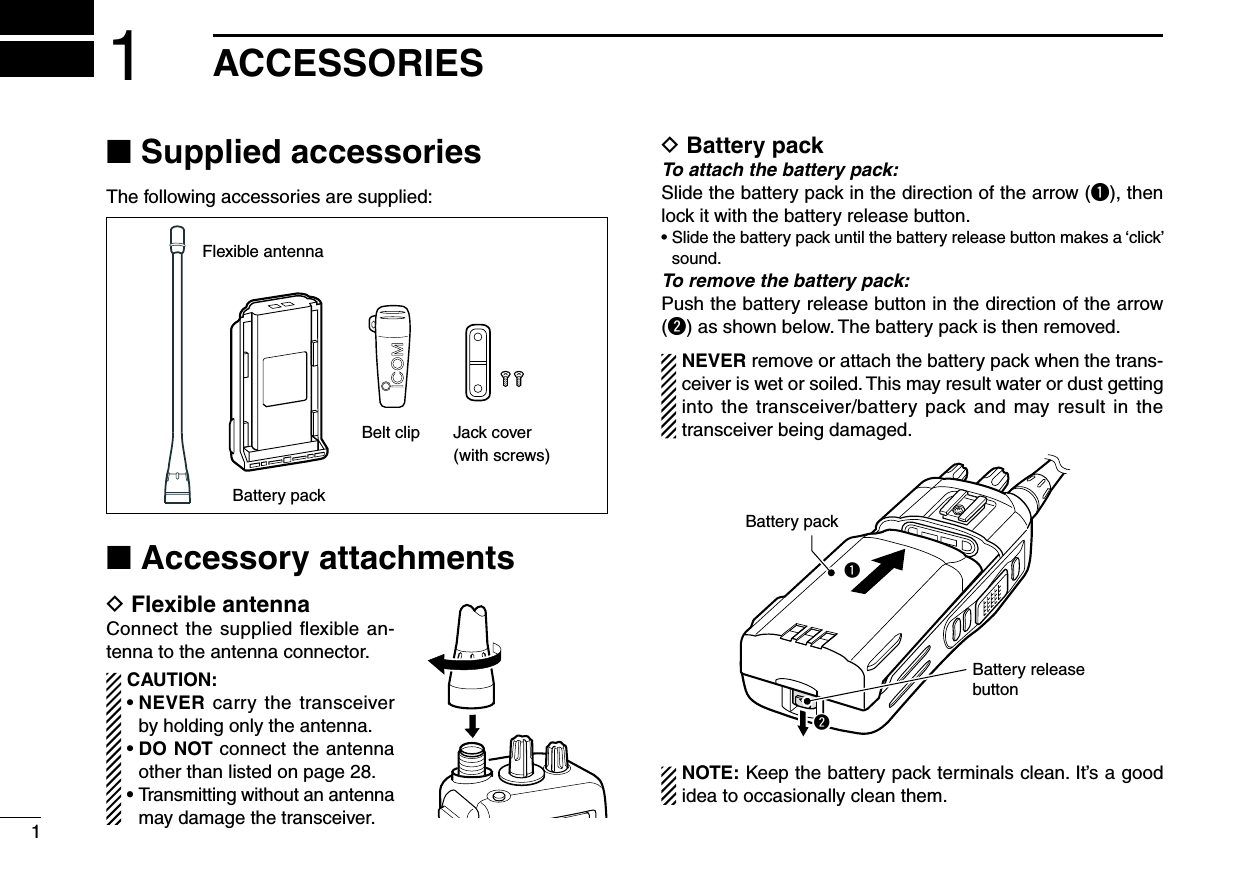
![32PANEL DESCRIPTION■ Front panelq ROTARY SELECTORSelects the pre-programmed system channels or talk groups (Max. 16) on the LTR/Passport system. (Depending on the pre-setting)w VOLUME CONTROL [VOL]Turns power ON and adjusts the audio level.e EMERGENCY KEYPush to transmit the DTMF emergency call.r [SP]/[MIC] JACKConnect the optional speaker-microphone. •Attachthejackcoverwhentheoptionalspeaker-microphoneisnot used. (p. 2)t FUNCTION DISPLAYDisplays a variety of information such as operating chan-nel name, DTMF encode channel, selected function, etc.y DEALER-PROGRAMMABLE KEYS [P0] to [P3]Desired functions can be programmed independently by your dealer.u 10-KEYPAD (Depending on version)Used to enter DTMF encode channel, phone number, etc.i UP/DOWN [∫]/[√] KEYS➥ Push to select the operating channel.➥ Push to select the talk group on the LTR or Passport system. (p. 9)o PTT SWITCH [PTT]Push and hold to transmit; release to receive.!0 MONITOR KEYPush to mute and release the CTCSS (DTCS) squelch mute. Open squelch/deactivate mute while pushing this key.!1 ANTENNA CONNECTORConnects the supplied antenna.itrqeuywo!0!110-keypad version](https://usermanual.wiki/ICOM-orporated/272102.Updated-User-Manual/User-Guide-1870944-Page-8.png)
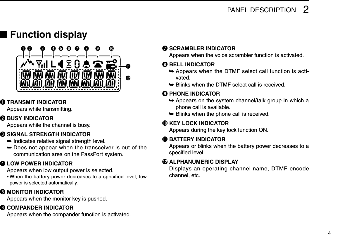
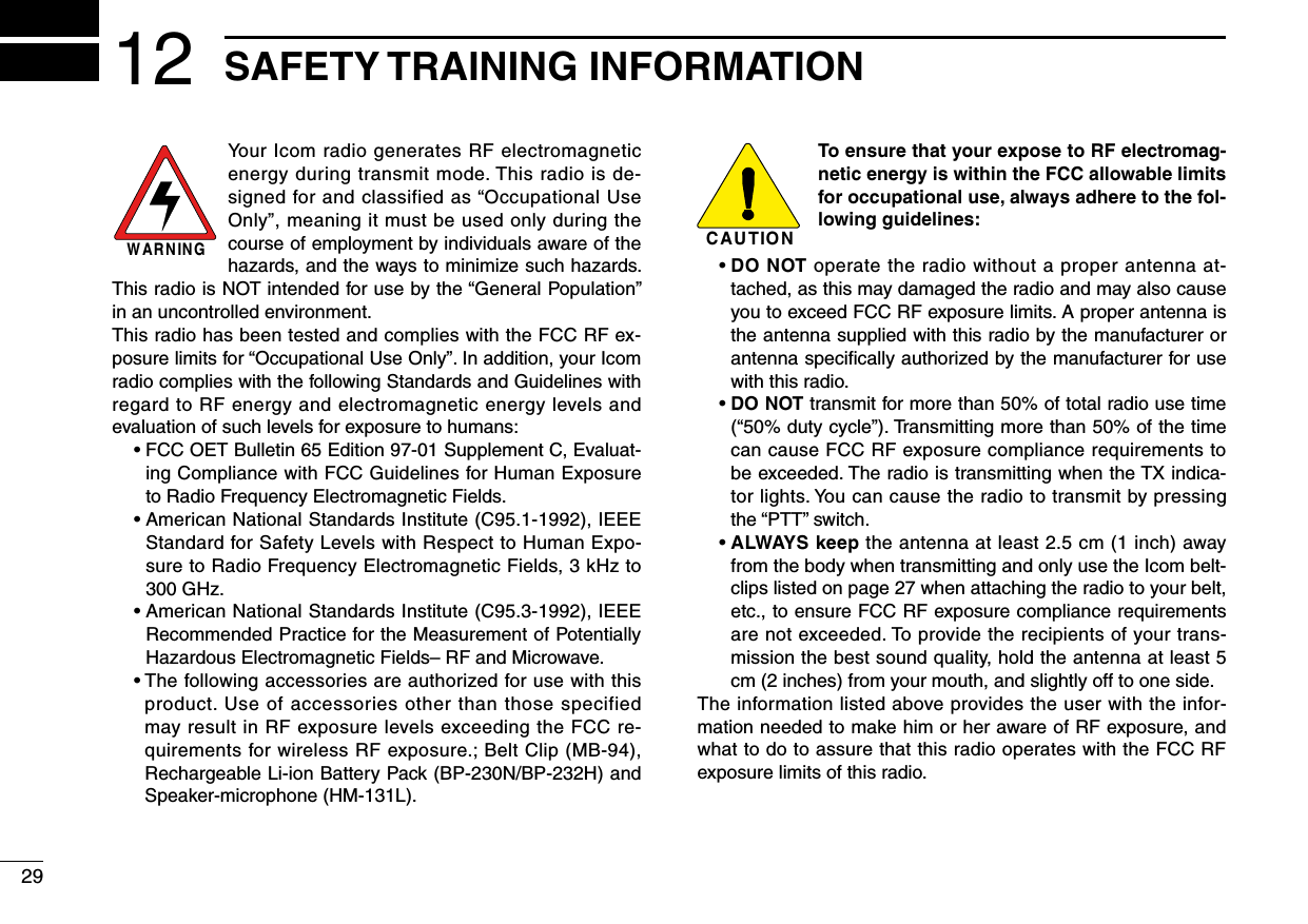
![52PANEL DESCRIPTION■ Programmable function keysThe following functions can be assigned to [P0], [P1], [P2], [P3], [Emergency], [Monitor], [M]* and [#]* programmable function keys. Consult your Icom dealer or system operator for details con-cerning your transceivers programming.If the programmable function names are bracketed in the following explanations, the specific key used to activate the function depends on programming.*Available on 10-keypad version only.SEND DTMF KEYPush to enter the DTMF encode channel selection mode.SELECT CALL KEY➥ Push to turn the DTMF select call mute function ON.➥ Push and hold to turn the DTMF select call mute function OFF.PRIORITY KEYPush to select the priority channel.EMERGENCY KEYPush to select the priority channel and automatically trans-mit a DTMF emergency call code.SCAN A KEY➥Thiskey’soperationdependsonthePowerONScanset-ting. When the power ON scan function is turned OFF; Push to start and cancel scanning operation. In case of transmission during scan, cancels scanning. When the power ON scan function is turned ON; Push to pause scanning. Scanning resumes after pass-ing a specified time period. In case of transmission during scan, pauses scanning. Scanning resumes after passing a specified time period specified. ➥ Push and hold this key for 1 sec. to indicate the scan group, then push to select the desired group.SCAN B KEY➥ Push to start and cancel scanning operation. In case of transmission during scan, pauses scanning. Scanning resumes after passing a specified time period. ➥ Push and hold this key for 1 sec. to indicate the scan group, then push to select the desired group.PRIORITY CHANNEL KEYS➥ Push to select Priority A or Priority B channel.➥ Push and hold [Prio A (Rewrite)] to rewrite the Prio A channel.](https://usermanual.wiki/ICOM-orporated/272102.Updated-User-Manual/User-Guide-1870944-Page-10.png)
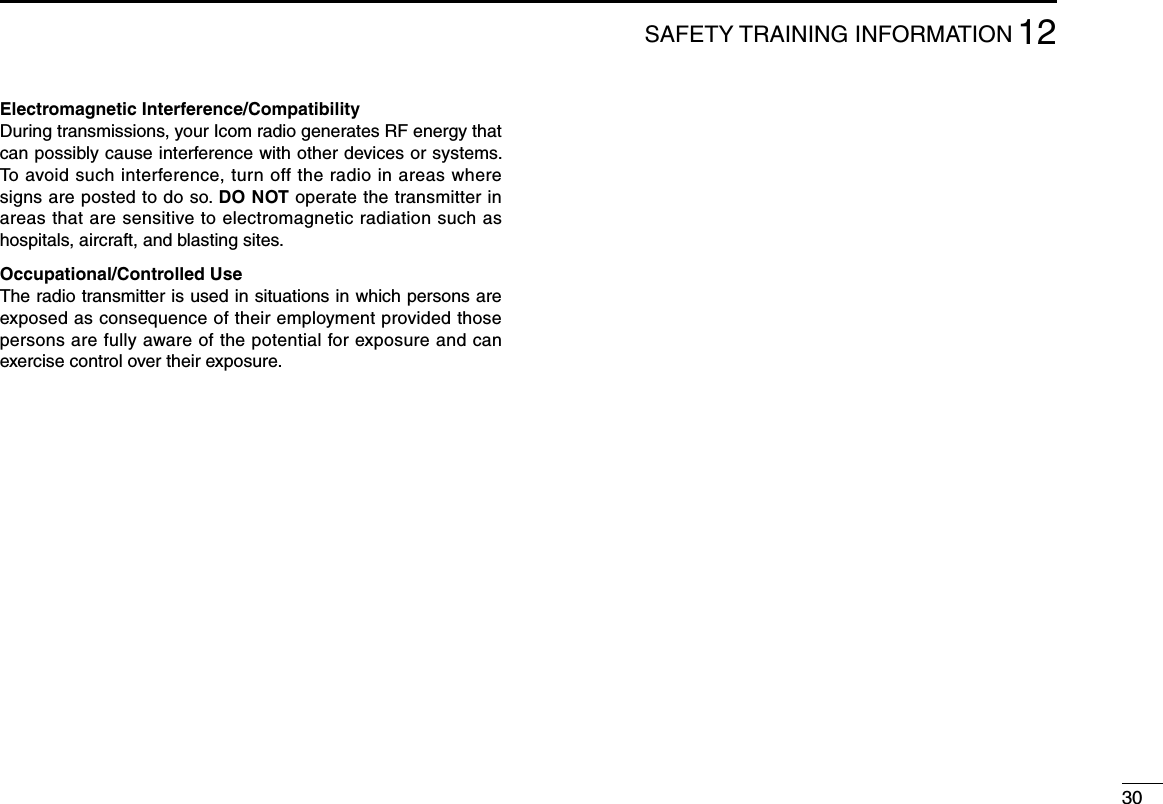
![62PANEL DESCRIPTIONMONITOR KEYPush to mute and release the CTCSS (DTCS) squelch mute. Open squelch/deactivate mute while pushing this key.NUISANCE DELETE KEYPush to cancel the displayed channel from the scan list in the talk group.SCAN TYPE KEYPush to toggle the scan type from Individual or Block.SPEED DIAL KEYPush to send the most recently transmitted DTMF code se-lected with [Send DTMF].TALK AROUND KEYTurn the talk around function ON and OFF. This function equalizes the transmit frequency to the receive frequency for transceiver-to-transceiver communication.WIDE/NARROW KEYPushtotoggletheIFpassbandwidthfrom“Wide”or“Nar-row”channelspacingforbothtransmissionandreceptiontemporarily. Once the channel or bank has changed, the passband width returns to the original setting.TX POWER KEYPush to toggle the transmit output power level from the inde-pendent settings of each channel.RE-DIAL KEYPush to send the most recently transmitted DTMF code ed-ited with 10-keypad.RSSI KEYPush to display the RSSI (Received Signal Strength Indica-tor) level.MODE DISPLAY TYPE KEYPush to toggle the scan mode display type from Individual and Block.LOCK KEYPush and hold for 2 sec. to turn the lock function ON and OFF.PHONE REQUEST KEYPush to turn the phone call function ON and OFF in the op-erating channel.](https://usermanual.wiki/ICOM-orporated/272102.Updated-User-Manual/User-Guide-1870944-Page-11.png)
![72PANEL DESCRIPTIONROAM REQUEST KEY➥ Push to return to the home site.➥ Push and hold to start roaming.SITE LOCK KEYPush to turn the Site Lock function ON and OFF. This function inhibits automatic roaming, and can be useful when the transceiver is out of the communication area such as on a subway or in an elevator.EMERGENCY KEYPush and hold for the specified time period to select the emergency channel and automatically send a DTMF emer-gency signal once or repeatedly.SCRAMBLER KEYPush to toggle the scrambler function ON or OFF.COMPANDER KEYPush to turn the compander function ON and OFF.The compander function reduces noise components from the transmitted audio to provide clear communication.USER SET MODE KEYPush for 1 sec. to enter the User set mode.The User set mode allows you to set seldom-changed set-tings.Push this key momentarily in the User set mode to select the function, and push [CH Up] or [CH Down] to change the setting.SIREN KEYPush to emit a siren. This function can be used for situations such as a security alarm for example.SELECT MODE KEY (available for Passport/LTR only)Push to select the operating mode from System or Talk Group.• System channel and talk group selectionq Push [Select Mode] to select the operating mode from System or Talk Group.w Then push [UP] or [DOWN] to select the desired system channel or talk group, in sequence.](https://usermanual.wiki/ICOM-orporated/272102.Updated-User-Manual/User-Guide-1870944-Page-12.png)
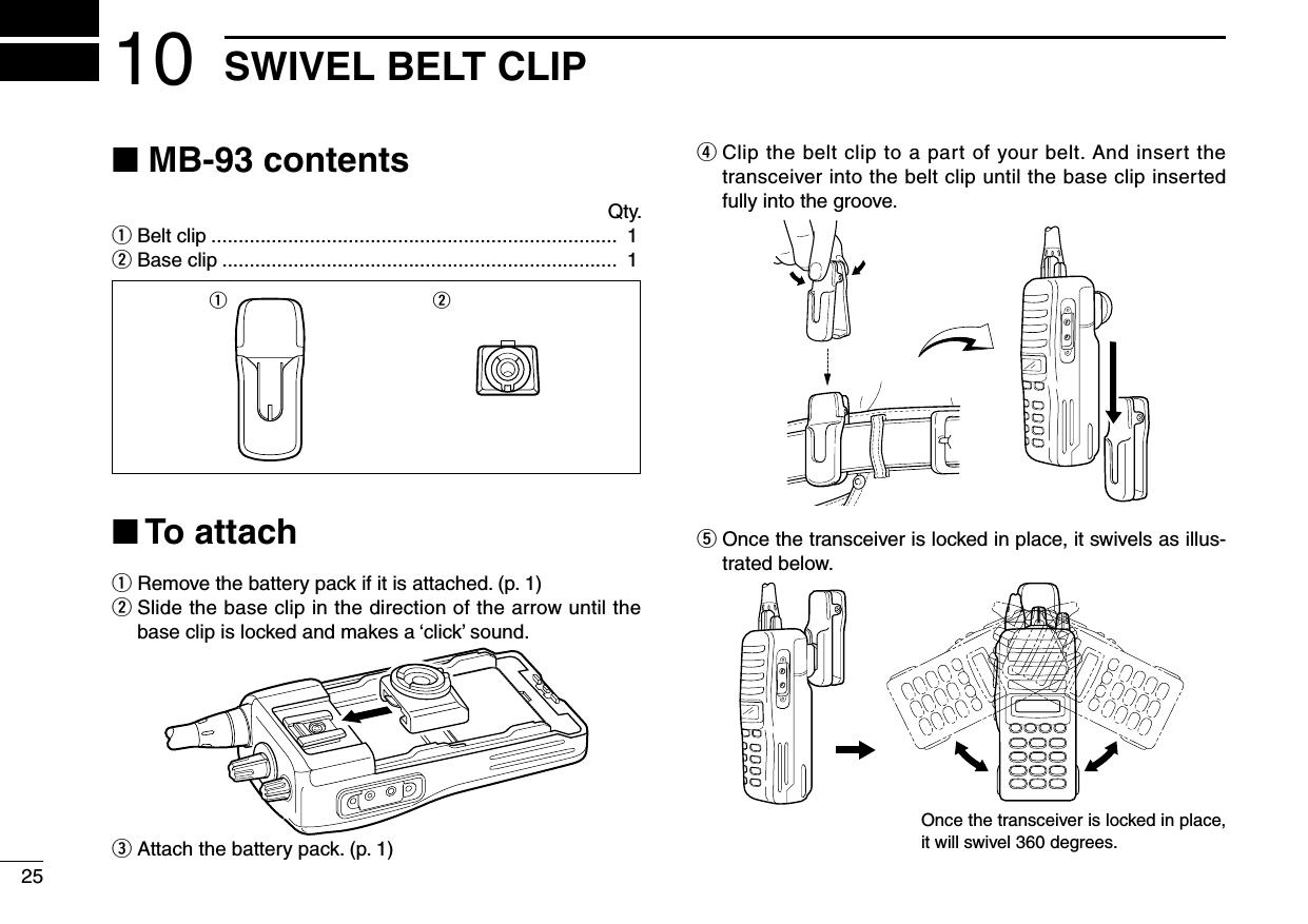
![83BASIC OPERATION■ Turning power ONq Rotate [VOL] to turn the power ON.w If the transceiver is programmed for a start up passcode, input the digit codes as directed by your dealer. •Thekeysinthetablebelowcanbeusedforpasswordinput: •Thetransceiverdetectsnumbersinthesameblockasidentical.Therefore“01234”and“56789”arethesame.eWhenthe“PASSWORD”indicationdoesnotclearafterin-putting 4 digits, the input code number may be incorrect. Turn the power off and start over in this case.■ Channel selectionPush [UP] or [DOWN], or rotate [ROTARY SELECTOR] to select the desired system channel or talk group, in se-quence.•Upto16pre-programmedchannelscanbeselectedvia[ROTARY SELECTOR].■ Call procedureWhen your system employs tone signalling (excludingCTCSS and DTCS), the call procedure may be necessary prior to voice transmission. The tone signalling employed may be a selective calling system which allows you to call specific station(s) only and prevent unwanted stations from contact-ing you.q Select the desired DTMF encode channel according to yourSystemOperator’sinstructions. •Thismaynotbenecessarydependingonprogramming. •Refertopages10,13or15forselection.w Push the [PTT].e After transmitting a DTMF code, the remainder of your communication can be carried out in the normal fashion.Selective calling Non-selective callingKEYNUMBER 0549382716UP](https://usermanual.wiki/ICOM-orporated/272102.Updated-User-Manual/User-Guide-1870944-Page-13.png)
![94PASSPORT OPERATION■ Receiving a callD Group callq Push [UP] or [DOWN], or rotate [ROTARY SELECTOR] to select the Passport system channel or talk group.wWhenacallisreceived; •“ ”andthecallingstationname/IDappear.e Push and hold [PTT], then speak into the microphone at a normal voice level.r Release [PTT] to return to receive.D Individual callq Push [UP] or [DOWN], or rotate [ROTARY SELECTOR] to select the Passport system channel or talk group.wWhenacallisreceived; •“ ”andthecallingstationname/IDappear.e Push and hold [PTT], then speak into the microphone at a normal voice level.r Release [PTT] to return to receive.t To finish the conversation, push [DOWN] to send the “ClearDown”signal.D Selective call (DTMF call) —Optional UT-108 is required—q Push [UP] or [DOWN], or rotate [ROTARY SELECTOR] to select the Passport system channel or talk group.w Push [Select call] to mute the channel. •“ ”appears.AppearseWhenreceivingacall,thecallingstationnameappearsand a beep is emitted. Then the mute is released. •“ ”disappears.D Phone callq Push [UP] or [DOWN], or rotate [ROTARY SELECTOR] to select the Passport system channel or talk group.wWhenaphonecallisreceived(transceiverrings),pushand hold [PTT], then speak into the microphone at a nor-mal voice level. •“ ”blinksandcallingstationname/IDappearsfor1sec.Blinkse Release [PTT] to return to receive.r Push [#] while pushing [PTT] to finish the communication.](https://usermanual.wiki/ICOM-orporated/272102.Updated-User-Manual/User-Guide-1870944-Page-14.png)
![104PASSPORT OPERATION■ Transmitting a callD Group callq Push [UP] or [DOWN], or rotate [ROTARY SELECTOR] to select the Passport system channel or talk group in which the group ID is pre-programmed.wWhilepushingandholding[PTT], speak into the micro-phone at a normal voice level after a beep is emitted. •Ifanerrorbeepisemitted,release[PTT]. After a while, repeat step w again. •ThebeepcanbeturnedOFFinUsersetmode. •Whenthetransceiverisoutofthecommunicationarea,“ ”disappears,and“NOSVC”messageappears.D Individual callq Push [UP] or [DOWN], or rotate [ROTARY SELECTOR] to select the Passport system channel or talk group in which the MID (Mobile ID) is pre-programmed.wWhilepushingandholding[PTT], speak into the micro-phone at a normal voice level after a beep is emitted. •Ifanerrorbeepisemitted,release[PTT]. After a while, repeat step w again. •ThebeepcanbeturnedOFFinUsersetmode. •Whenthetransceiverisoutofthecommunicationarea,“ ”disappears,and“NOSVC”messageappears.e To finish the conversation, push [DOWN] to send the “ClearDown”signal.D Selective call (DTMF call) —Optional UT-108 is required—q Push [UP] or [DOWN], or rotate [ROTARY SELECTOR] to select the Passport system channel or talk group.w Push [Send DTMF]— a DTMF encode channel appears.e Push [UP] or [DOWN] to select the desired DTMF en-code channel.r Push [PTT] to transmit the selected DTMF code in the selected DTMF channel. •Push[P0] to cancel the DTMF transmission.D Phone call (Available for 10-keypad version only)q Push [UP] or [DOWN], or rotate [ROTARY SELECTOR] to select the Passport system channel or talk group.w Push [Phone request] to enable the phone call. •“ ”appears.Appearse Push [PTT] to connect the phone line. •Theproceedtoneisemittedafterconnectiontothephoneline.r Whilepushingandholding[PTT], enter the phone number via the 10-keypad to make the call. Then release [PTT].t Push [PTT] to transmit; release to receive.y Push [#] while pushing [PTT] to finish the communication.](https://usermanual.wiki/ICOM-orporated/272102.Updated-User-Manual/User-Guide-1870944-Page-15.png)
![114PASSPORT OPERATION■ Other functionsD Manual roaming start function If the transceiver has [Roam Request] assigned to it, you can start roaming manually to search for another site.q Push [UP] or [DOWN], or rotate [ROTARY SELECTOR] to select the Passport system channel or talk group.w Push and hold [Roam Request] to start roaming. •“ROAMSITE”isdisplayed. •When“INVALID”isdisplayed,thehomerepeatermaynothavea neighbour site. After a while, repeat step w.e Push [Roam Request] to cancel roaming.D Site lock functionIf the transceiver has [Site Lock] assigned to it, automatic roaming can be inhibited. This function is useful when the transceiver is out of the communication area such as on a subway or in an elevator.q Push [UP] or [DOWN], or rotate [ROTARY SELECTOR] to select the Passport system channel or talk group.w Push [Site Lock] to turn the site lock function ON and OFF. •“SITELOCK”isdisplayed.](https://usermanual.wiki/ICOM-orporated/272102.Updated-User-Manual/User-Guide-1870944-Page-16.png)
![125LTR OPERATION■ Receiving a callD Group callq Push [UP] or [DOWN], or rotate [ROTARY SELECTOR] to select the LTR system channel or talk group.wWhenacallisreceived; •“ ”andthecallingstationname/IDappear.e Push and hold [PTT], then speak into the microphone at a normal voice level.r Release [PTT] to return to receive.D Selective call (DTMF call) —Optional UT-108 is required—q Push [UP] or [DOWN], or rotate [ROTARY SELECTOR] to select the LTR system channel or talk group.w Push [Select call] to mute the channel. •“ ”appears.AppearseWhenreceivingacall,thecallingstationnameappearsand a beep is emitted. Then the mute is released. •“ ”disappears.D Phone callq Push [UP] or [DOWN], or rotate [ROTARY SELECTOR] to select the LTR system channel or talk group.wWhenaphonecallisreceived(transceiverrings),pushand hold [PTT], then speak into the microphone at a normal voice level. •“ ”blinksandcallingstationname/IDappearsfor1sec.Blinkse Release [PTT] to return to receive.r Push [#] while pushing [PTT] to finish the communication.](https://usermanual.wiki/ICOM-orporated/272102.Updated-User-Manual/User-Guide-1870944-Page-17.png)
![135LTR OPERATION■ Transmitting a callD Group callq Push [UP] or [DOWN], or rotate [ROTARY SELECTOR] to select the LTR system channel or talk group.wWhilepushingandholding[PTT], speak into the micro-phone at a normal voice level after a beep is emitted. •Ifanerrorbeepisemitted,release[PTT]. After a while, repeat step w. •ThebeepcanbeturnedOFFinUsersetmode.D Selective call (DTMF call) —Optional UT-108 is required—q Push [UP] or [DOWN], or rotate [ROTARY SELECTOR] to select the LTR system channel or talk group.w Push [Send DTMF]— a DTMF encode channel appears.e Push [UP] or [DOWN] to select the desired DTMF en-code channel.r Push [PTT] to transmit the selected DTMF code in the selected DTMF channel. •Push[Send DTMF] to cancel the DTMF transmission.](https://usermanual.wiki/ICOM-orporated/272102.Updated-User-Manual/User-Guide-1870944-Page-18.png)
![146CONVENTIONAL OPERATION■ Receiving and transmitting NOTE: Transmitting without an antenna may damage the transceiver. See page 1 for antenna attachment.Receiving:q Rotate [VOL] to turn the power ON.w Push [UP] or [DOWN], or rotate [ROTARY SELECTOR] to select the conventional system channel, in sequence.eWhenreceivingacall,adjusttheaudiooutputleveltoacomfortable listening level.Transmitting:Waitforthechanneltobecomecleartoavoidinterference.qWhilepushingandholding[PTT], speak into the micro-phone at a normal voice level.w Release [PTT] to return to receive. IMPORTANT: To maximize the readability of your signal; 1. Pause briefly after pushing [PTT]. 2. Hold the microphone 5 to 10 cm (2 to 4 inches) from your mouth, then speak into the microphone at a nor-mal voice level.D Transmitting notes• Transmit inhibit functionThe transceiver has several inhibit functions which restrict transmission under the following conditions:- Channel is busy.- Un-matched (or matched) CTCSS is received.-Theselectedchannelisa‘receiveonly’channel.• Time-out timerAfter continuous transmission for the pre-programmed time period, the time-out timer is activated, causing the trans-ceiver to stop transmitting.• Penalty timerOnce the time-out timer is activated, transmission is further inhibited for a period determined by the penalty timer.](https://usermanual.wiki/ICOM-orporated/272102.Updated-User-Manual/User-Guide-1870944-Page-19.png)
![156CONVENTIONALOPERATIOND DTMF receiving and transmitting —Optional UT-108 is required—If the transceiver has [Send DTMF] assigned to it, a DTMF encode channel is displayed when pushed, and as-signed DTMF encode channels can be selected via [UP] or [DOWN].Receiving:q Push [UP] or [DOWN], or rotate [ROTARY SELECTOR] to select the conventional system channel, in sequence.w Push [Select call] to mute the channel. (“ ”appears)eWhenreceivingacall,abeepisemittedandmuteisre-leased. (“ ”disappears)Transmitting:q Push [UP] or [DOWN], or rotate [ROTARY SELECTOR] to select the conventional system channel, in sequence.w Push [Send DTMF]— a DTMF encode channel appears.e Push [UP] or [DOWN] to select the desired DTMF en-code channel.r Push [PTT] to transmit the selected DTMF code in the selected DTMF channel. •Push[P0] to cancel the DTMF transmission.■ User set modeIf the transceiver has [User Set Mode] assigned to it, you can“customize”thetransceiveroperationtosuityourprefer-ences and operating style.Entering the user set mode:q Push and hold [User Set Mode] to enter user set mode. Push [User Set Mode] momentarily to select the item. Then push [UP] or [DOWN] to set the desired level/condi-tion. Available set mode functions: •Backlight :ON,AutoorOFF •Ringer :ONorOFF •Beep :ONorOFF •SQLLevel :0to255 •MicGain :1to5 •BatteryVoltage :ONorOFF •SystemInformation :ONorOFF •Run-Time :Thetransceiver’srunningtimeisdisplayed.w Push and hold [User Set Mode] to exit user set mode.](https://usermanual.wiki/ICOM-orporated/272102.Updated-User-Manual/User-Guide-1870944-Page-20.png)
![166CONVENTIONALOPERATION■ Emergency transmissionWhen[Emergency] is pushed and held for the specified time period, the DTMF emergency signal is automatically transmitted once or repeatedly on the emergency channel.However, when no emergency channel is specified, the sig-nal is transmitted on the previously selected channel.If you want to cancel the emergency call, push and hold the key again before transmitting the call.■ Scrambler functionThe voice scrambler function provides private communi-cation between stations. The frequency inversion type is equipped to all versions, moreover, the optional Rolling or Non-rolling type can be available.q Push [Scrambler] to turn the scrambler function ON. •“ ”appears.w Push [Scrambler] again to turn the scrambler function OFF. •“ ”disappears.■ Stun functionWhenthespecifiedcode,setasastuncode,isreceived,thestunfunctionwillbeactivated.Whenthestuncodeisreceived,“STUNNED”appearsonthedisplayandthetrans-ceiver cannot be used. To use the transceiver, the stun re-lease code must be received.Also,ifthetransceiver’srunningtimeexceedsthepresetrunning time limit, the transceiver cannot be used. To use the transceiver, extend the running time limit or turn the Run Time Limit function OFF using the CS-F43TR c l o n i n g s o f t -w a r e .■ Man Down transmissionWhentheoptionalUT-124man d o w n unit is installed, the Man Down function can be used. The Man Down function transmits a man down emergency call after the specified time period has passed with the transceiver in a horizontal position.](https://usermanual.wiki/ICOM-orporated/272102.Updated-User-Manual/User-Guide-1870944-Page-21.png)
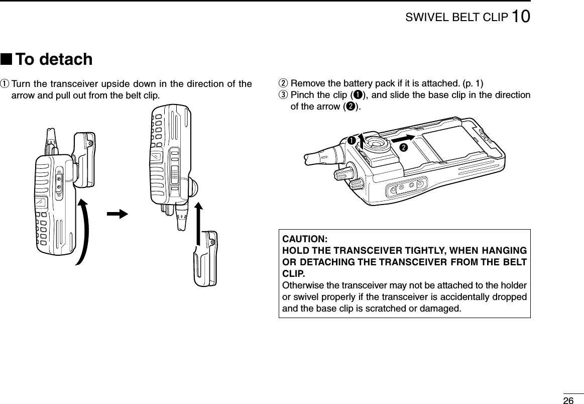
![177OPTIONAL UNIT INSTALLATION■ UT-124 installationInstall the optional UT-124 m a n d o w n u n i t as follows:q Rotate [VOL] to turn the power OFF, and remove the bat-tery pack. (p. 1)w Remove the unit cover. NOTE: Use a flat head screw driver or a similar flat instrument, and insert into the hollow of the chassis, then lift and take away the unit cover. (The removed cover cannot be used again.)e Install the unit as shown below.r Replace the unit cover and the battery pack, then rotate [VOL] to turn the power ON.■ UT-108 installationInstall the optional UT-108 d t m f d e c o d e r u n i t as follows:q Rotate [VOL] to turn the power OFF, and remove the bat-tery pack. (p. 1)w Remove the unit cover as shown at left.e Cut and solder the pattern on the PCB at the RX AF cir-cuit as shown below.r Install the UT-108 d t m f d e c o d e r u n i t the same way as de-scribed in the optional UT-124 installation as shown at left.t Replace the unit cover and the battery pack, then rotate [VOL] to turn the power ON. NOTE: Be sure to un-solder A and B, and re-solder B and C, otherwise no AF output is available when you remove the DTMF decoder unit.ABC](https://usermanual.wiki/ICOM-orporated/272102.Updated-User-Manual/User-Guide-1870944-Page-22.png)
![187OPTIONAL UNIT INSTALLATION■ UT-109 and UT-110 installationInstall the optional UT-109/UT-110 scrambler units as fol-lows:q Rotate [VOL] to turn the power OFF, and remove the bat-tery pack. (p. 1)w Remove the unit cover as shown on page 17 (UT-124 in-stallation).e Cut the pattern on the PCB at the TX mic circuit (C) and RX AF circuit (F) as shown below.r Install the UT-109/UT-110 s c r a m b l e r u n i t s as described in the optional UT-124 installation. (p. 17)t Replace the unit cover and the battery pack, then rotate [VOL] to turn the power ON. NOTE: Be sure to re-solder the disconnected points at left, otherwise no TX modulation or AF output is available when you remove the scrambler units.](https://usermanual.wiki/ICOM-orporated/272102.Updated-User-Manual/User-Guide-1870944-Page-23.png)