ICOM orporated 272103 UHF Transceiver User Manual Updated
ICOM Incorporated UHF Transceiver Updated
Contents
- 1. Users Manual
- 2. Updated User Manual
Updated User Manual
INSTRUCTION MANUAL
This device complies with Part 15 of the FCC Rules.
Operation is subject to the condition that this device does not
cause harmful interference.
iF43GT/GS
UHF TRANSCEIVER
iF33GT/GS
VHF TRANSCEIVER

i
R CAUTION! NEVER hold the transceiver so that
the antenna is very close to, or touching exposed parts of
the body, especially the face or eyes, while transmitting. The
transceiver will perform best if the microphone is 2 to 4 in. (5
to 10 cm) away from the lips and the transceiver is vertical.
R CAUTION! NEVER operate the transceiver with a
headset or other audio accessories at high volume levels.
R CAUTION! NEVER short the terminals of the bat-
tery pack.
DO NOT push PTT when not actually desiring to transmit.
DO NOT use or place the transceiver in direct sunlight or
in areas with temperatures below +22°F (–30°C) or above
+140°F (+60°C).
The basic operations, transmission and reception of the
transceiver are guaranteed within the specified operating
temperature range. However, the LCD display may not be
operate correctly, or show an indication in the case of long
hours of operation, or after being placed in extremely cold
areas.
PRECAUTION
READ ALL INSTRUCTIONS carefully and com-
pletely before using the transceiver.
SAVE THIS INSTRUCTION MANUAL — This
instruction manual contains important oper ating instructions
for the IC-F33GT/GS VHF TRANSCEIVER and IC-F43GT/
GS UHF TRANSCEIVER.
IMPORTANT
Icom, Icom Inc. and the Icom logo are registered trademarks of Icom Incor-
porated (Japan) in Japan, the United states, the United Kingdom, Germany,
France, Spain, Russia and/or other countries.
WORD DEFINITION
RDANGER Personal death, serious injury or an ex-
plosion may occur.
RWARNING Personal injury, fire hazard or electric
shock may occur.
CAUTION Equipment damage may occur.
NOTE
If disregarded, inconvenience only. No risk
of personal injury, fire or electric shock.
EXPLICIT DEFINITIONS

ii
PRECAUTION
DO NOT modify the transceiver for any reason.
KEEP the transceiver from the heavy rain, and Never
immerse it in the water. The transceiver construction is water
resistant, not waterproof.
The use of non-Icom battery packs/chargers may impair
transceiver performance and invalidate the warranty.
Icom optional equipment is designed for optimal perform-
ance when used with this transceiver. We are not respon-
sible for the transceiver being damaged or any accident
caused when using non-Icom optional equipment.
For U.S.A. only
CAUTION: Changes or modifications to this transceiver, not
expressly approved by Icom Inc., could void your authority to
operate this transceiver under FCC regulations.

iii
IMPORTANT .................................................................................... i
EXPLICIT DEFINITIONS ................................................................. i
PRECAUTION ................................................................................. i
TABLE OF CONTENTS ................................................................. iii
1 ACCESSORIES .................................................................... 1–3
■ Supplied accessories ............................................................ 1
■ Accessory attachments ......................................................... 1
2 PANEL DESCRIPTION ...................................................... 4–10
■ Front panel ............................................................................ 4
■ Function display .................................................................... 6
■ Programmable function keys ................................................. 7
3 BASIC OPERATION ......................................................... 11–15
■ Turning power ON ............................................................... 11
■ Channel selection ............................................................... 11
■ Call procedure ...................................................................... 12
■ Receiving and transmitting ................................................... 12
■ User Set mode ..................................................................... 15
■ Scrambler function ............................................................... 15
4 BIIS OPERATION ............................................................. 16–27
■ Default setting ..................................................................... 16
■ Receiving a call ................................................................... 16
■ Transmitting a call ................................................................ 18
■ Receiving a message .......................................................... 20
■ Transmitting a status ........................................................... 22
■ Transmitting an SDM ........................................................... 23
■ Position data transmission .................................................. 25
■ Printer connection ............................................................... 25
■ Digital ANI ........................................................................... 25
■ Auto emergency transmission ............................................. 26
■ Stun function ....................................................................... 26
■ BIIS indication ..................................................................... 26
■ Priority A channel selection ................................................. 26
■ Man Down Emergency Call ................................................. 27
5 MDC 1200 OPERATION ................................................... 28–33
■ MDC 1200 system operation ............................................... 28
■ Transmitting a call ................................................................ 28
■ Receiving a call ................................................................... 33
6 OPTIONAL UNIT INSTALLATION ................................... 34–35
■ Optional unit installation ...................................................... 34
■ UT-109 and UT-110 installation ........................................... 35
7 BATTERY CHARGING ..................................................... 36–40
■ Caution ................................................................................ 36
■ Optional battery chargers .................................................... 38
8 BATTERY CASE .................................................................... 41
■ Optional battery case (BP-240) ........................................... 41
9 SWIVEL BELT CLIP ......................................................... 42–43
■ MB-93 contents ................................................................... 42
■ To attach .............................................................................. 42
■ To detach ............................................................................. 43
10 OPTIONS .......................................................................... 44–45
11 SAFETY TRAINING INFORMATION ................................ 46–47
TABLE OF CONTENTS
1
1
ACCESSORIES
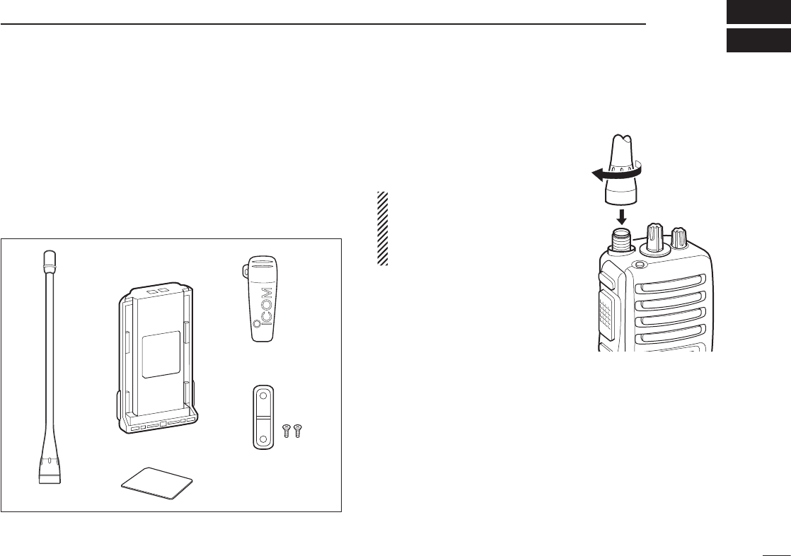
■ Supplied accessories
The following accessories are supplied: Qty.
q Flexible antenna ...............................................................1
w Battery pack .....................................................................1
e Belt clip ............................................................................1
r Unit cover (double-sided tape)* ........................................1
t Jack cover (with screws) ............................................1 set
*Use the unit cover as a spare. Ask your dealer for details.
■ Accessory attachments
D Flexible antenna
Connect the supplied flexible anten-
na to the antenna connector.
CAUTION:
• NEVER HOLD by the antenna
when carrying the transceiver.
• Transmitting without an antenna
may damage the transceiver.
qw
r
e
t
2
1ACCESSORIES
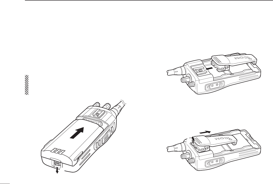
D Battery pack
To attach the battery pack:
Slide the battery pack in the direction of the arrow (q), then
lock it with the battery release button.
• Slide the battery pack until the battery release button makes a
‘click’ sound.
To release the battery pack:
Push the battery release button in the direction of the arrow
(w) as shown below. The battery pack is then released.
NEVER release or attach the battery pack when the trans-
ceiver is wet or soiled. This may result water or dust get-
ting into the transceiver/battery pack and may result in the
transceiver being damaged.
D Belt clip
To attach the belt clip:
q Release the battery pack if it is attached.
w Slide the belt clip in the direction of the arrow until the belt
clip is locked and makes a ‘click’ sound.
To detach the belt clip:
q Release the battery pack if it is attached.
w Pinch the clip (q), and slide the belt clip in the direction
of the arrow (w).
q
w
q
w
3
1
ACCESSORIES
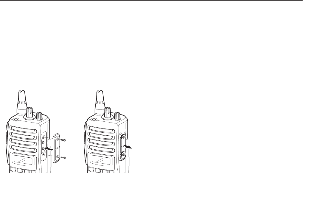
D Jack cover
Attach the jack cover when the optional speaker-microphone
is not used.
To attach the jack cover:
q Attach the jack cover on
the [SP]/[MIC] jack.
w Tighten the screws.
To detach the jack cover:
q Unscrew the screws with
a Phillips screwdriver.
w Detach the jack cover for
the speaker-microphone
connection.
q
w
q
w
4
2PANEL DESCRIPTION
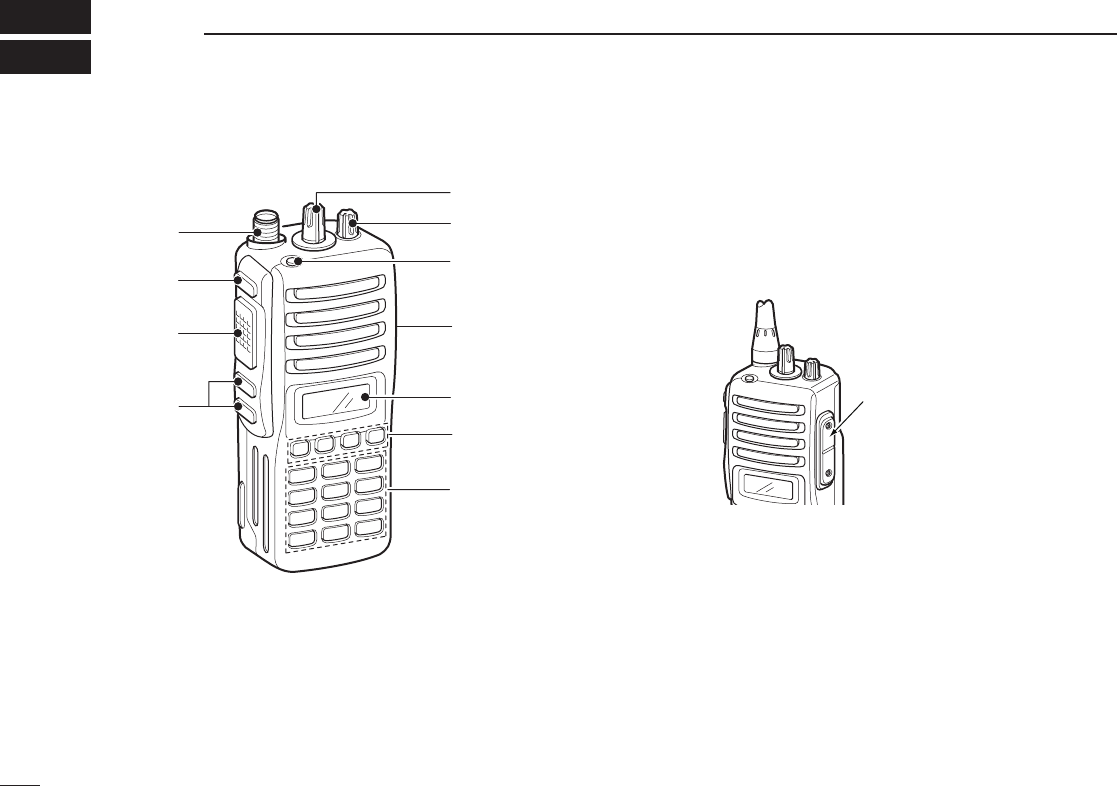
■ Front panel
q ROTARY SELECTOR
Rotate to select the pre-programmed memory channels
or the operating bank.
(Depending on the pre-setting)
w VOLUME CONTROL [VOL]
Rotate to turn the power ON/OFF and adjusts the audio
level.
e DEALER-PROGRAMMABLE KEY [RED]
Desired function can be programmed by your dealer.
(p. 7)
r [SP]/[MIC] JACK
Connect the optional speaker-microphone.
t FUNCTION DISPLAY
Displays a variety of information such as an operating
channel number/name, 2/5-tone code, DTMF numbers,
selected function, etc.
y DEALER-PROGRAMMABLE KEYS [P0] to [P3]
Desired functions can be programmed independently by
your dealer. (p. 7)
[SP]/[MIC] jack cover
NOTE: Attach the [SP]/[MIC] jack
cover when the optional
speaker-microphone is not used.
(See p. 3 for details)
it
r
q
e
u
y
w
o
!0
!1
10-keypad version

5
2
PANEL DESCRIPTION
u 10-KEYPAD (Depending on version)
The keypad allows you to enter digits to:
• Select memory channels
• Select tone channels
• Select DTMF codes (during transmit)
• Set TX codes
• Set BIIS status number
• Input text message for SDM operation
• Start up with the password
i UP/DOWN KEYS
➥ Push to select an operating channel.
➥ Push to select a TX code channel after pushing
[TX CODE CH SELECT].
➥ Push to select a DTMF channel after pushing [DTMF].
➥ Push to select a scan group after pushing and holding
[SCAN].
➥ Push to select a BIIS code, status number or SDM
after pushing [DIGITAL].
* Desired functions can be programmed independently by your
dealer. (p. 7)
o PTT SWITCH [PTT]
➥ Push and hold to transmit; release to receive.
➥ Push to transmit the call during MSK operation,
depending on the setting.
!0 MONITOR KEY
➥Mute and release the CTCSS (DTCS) or 2-tone
squelch mute. Open any squelch/deactivate any mute
while pushing this key. (LMR operation only)
➥ Activates one of (or two of) the following functions on
each channel independently.
(PMR or BIIS PMR operation only)
• Push and hold the key to unmute the channel (audio is
emitted; ‘audible’ condition).
• Push the key to toggle the mute and unmute conditions
(toggles ‘audible’ and ‘inaudible’).
• Push the key to mute the channel (sets to ‘inaudible’ only).
• Push the key to unmute the channel (sets to ‘audible’ only).
• Push the key after communication is nished to send a ‘reset
code.’
• Push the key after communication is nished to send a ‘clear
down code’ during BIIS operation on an MSK channel.
NOTE: The unmute condition (‘audible’ conditions)
may automatically return to the mute condition
(‘inaudible’ condition) after a specified period.
* Desired function can be programmed by your dealer. (p. 7)
!1 ANTENNA CONNECTOR
Connects the supplied antenna.
6
2PANEL DESCRIPTION
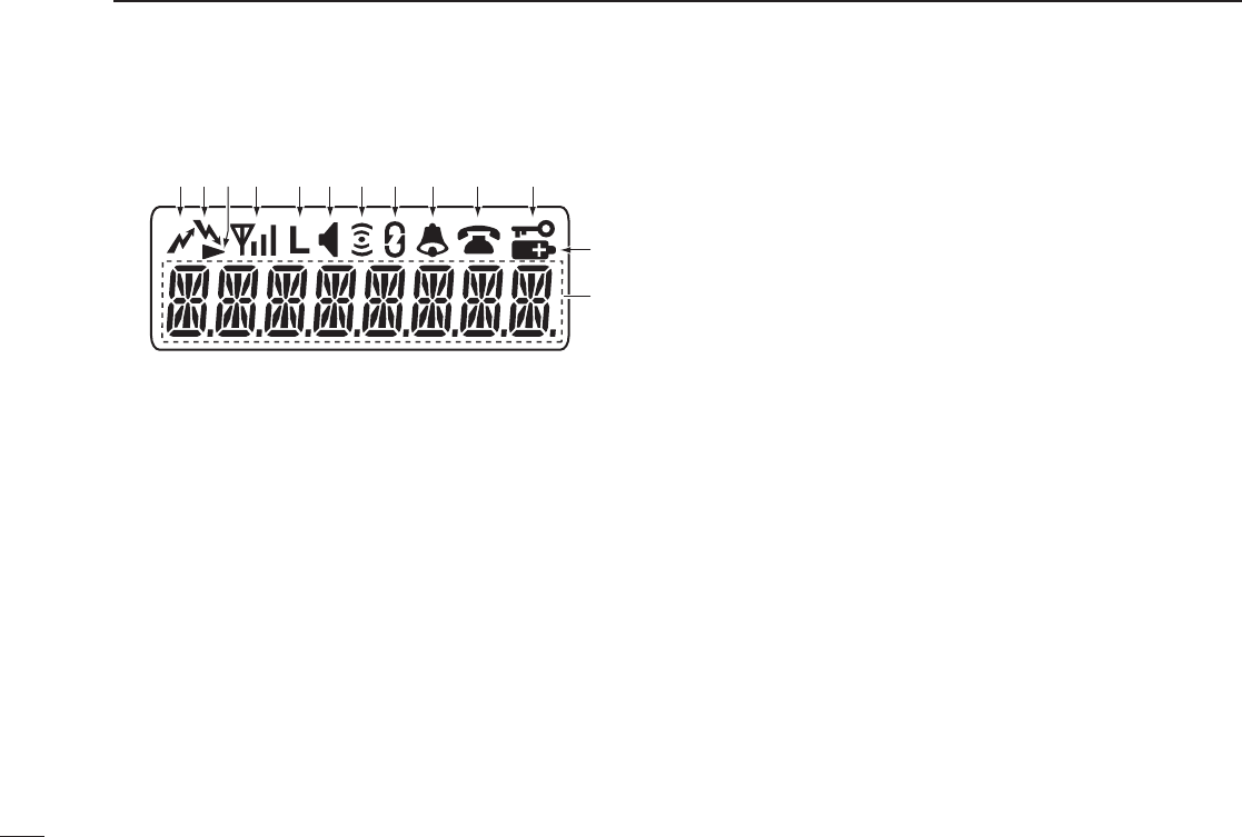
■ Function display
q TRANSMIT INDICATOR
Appears while transmitting.
w BUSY INDICATOR
Appears while the channel is busy.
e SCROLL INDICATOR
Appears when a received SDM including more than 8
characters is displayed.
r SIGNAL STRENGTH INDICATOR
Indicates relative signal strength level.
t LOW POWER INDICATOR
Appears when low output power is selected.
• When the battery power decreases to a specified level, low
power is selected automatically.
y AUDIBLE INDICATOR
➥ Appears when the channel is in the ‘audible’ (unmute)
condition.
➥ Appears when the specified 2/5-tone/BIIS code is
received.
u COMPANDER INDICATOR
Appears when the compander function is activated.
i SCRAMBLER INDICATOR
Appears when the voice scrambler function is activated.
o BELL INDICATOR
Appears/blinks when the specific 2/5-tone/BIIS code is
received, according to the pre-programming.
!0 CALL CODE MEMORY INDICATOR
Appears when the call code memory is selected.
!1 KEY LOCK INDICATOR
Appears during the key lock function is ON.
!2 BATTERY INDICATOR
Appears or blinks when the battery power decreases to a
specified level.
!3 ALPHANUMERIC DISPLAY
Displays an operating channel number, channel name,
Set mode contents, DTMF code, etc.
q !1!0oiuytrew
!2
!3

7
2
PANEL DESCRIPTION
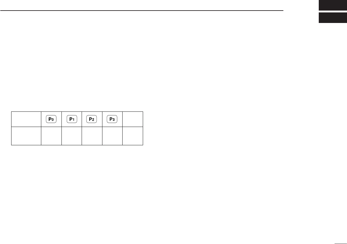
■ Programmable function keys
The following functions can be assigned to [UP], [DOWN],
[P0], [P1], [P2], [P3], [RED] and [MONITOR] programmable
function keys.
Consult your Icom dealer or system operator for details con-
cerning your transceivers programming.
If the programmable function names are bracketed in the fol-
lowing explanations, the specific key is used to activate the
function depends on the programming.
CH UP AND DOWN KEYS
➥ Push to select an operating channel.
➥ Push to select a transmit code channel after pushing [TX
Code CH Select].
➥ Push to select a DTMF channel after pushing [DTMF
Autodial].
➥ Push to select a scan group after pushing and holding
[Scan A Start/Stop]/[Scan B Start/Stop].
➥ Push to select a BIIS code, status number or SDM after
pushing [Digital].
➥ Push to select the MDC menu after pushing [MDC CALL].
➥ Push to select the desired transceiver alias or message
channel while in the transceiver alias or message channel
selection mode.
BANK SELECT KEY
Push this key, then push [CH Up] or [CH Down] to select the
desired bank.
SCAN A KEY
➥ This key’s operation depends on the Power ON Scan set-
ting.
When the power ON scan function is turned OFF;
Push to start and cancel scanning operation. In case of
transmission during scan, cancels scanning.
When the power ON scan function is turned ON;
Push to pause scanning. Scanning resumes after pass-
ing a specified time period. In case of transmission during
scan, pauses scanning. Scanning resumes after passing
a specified time period specified.
➥ Push and hold this key for 1 sec. to indicate the scan
group, then push [CH Up] or [CH Down] to select the
desired group.
SCAN B KEY
➥ Push to start and cancel scanning operation. In case of
transmission during scan, pauses scanning. Scanning
resumes after passing a specified time period.
➥
Push and hold this key for 1 sec. to indicate the scan group,
then push [CH Up] or [CH Down] to select the desired group.
SCAN TAG KEY
Push to add or delete the selected channel to the scan group.
PRIORITY CHANNEL KEYS
➥ Push to select Priority A or Priority B channel.
➥ Push and hold [Prio A (Rewrite)] to rewrite the Prio A
channel.

8
2PANEL DESCRIPTION
MR-CH 1/2/3/4 KEYS
Push to select an operating channel directly.
MONITOR KEY
➥ Mute and release the CTCSS (DTCS) or 2-tone squelch
mute. Open any squelch/deactivate any mute while push-
ing this key. (LMR operation only)
➥ Activates one of (or two of) the following functions on
each channel independently: (PMR or BIIS PMR opera-
tion only)
• Push and hold to un-mute the channel (audio is emitted;
‘Audible’ condition).
• Push to mute the channel (sets to ‘Inaudible’ only).
• Push to un-mute the channel (sets to ‘Audible’ only).
• Push after the communication is nished to send a ‘reset
code’.
NOTE: The un-mute condition (‘Audible’ condition) may
automatically return to the mute condition (‘Inaudible‘
condition) after a specified period.
LOCK KEY
Push and hold to electronically lock all programmable keys
except the following:
[Call] (incl. Call A and Call B), [Moni(Audi)] and [Emergency].
OUTPUT POWER SELECTION KEY
Push to select the transmit output power temporarily or per-
manently, depending on the pre-setting.
• Ask your dealer for the output power level for each selection.
C.TONE CHANNEL ENTER KEY
Push to select the continuous tone channel using
[CH Up]/[CH Down] to change the tone frequency/code set-
ting after pushing this key for permanent operation.
TALK AROUND KEY
Turn the talk around function ON and OFF.
• The talk around function equalizes the transmit frequency to the
receive frequency for transceiver-to-transceiver communication.
WIDE/NARROW KEY
Push to toggle the IF bandwidth between wide and narrow.
• The wide passband width can be selected from 25.0 or 20.0 kHz
using the CS-F33G c l o n i n g s o f t w a r e . (PMR or BIIS PMR opera-
tion only) Ask your Dealer for details.
DTMF AUTODIAL KEY
➥ Push to enter the DTMF channel selection mode. Then
select the desired DTMF channel using [CH Up]/[CH
Down] keys.
➥ After selecting the desired DTMF channel, push this key
to transmit the DTMF code.
DTMF RE-DIAL KEY
Push to transmit the last-transmitted DTMF code.
CALL KEYS
Push to transmit a 2/5-tone/BIIS ID code.
• Call transmission is necessary before you call another station
depending on your signalling system.
• [Call A] and/or [Call B] may be available when your system
employs selective ‘Individual/Group’ calls. Ask your dealer which
call is assigned to each key.

9
2
PANEL DESCRIPTION
EMERGENCY KEYS
➥ Push and hold to transmit an emergency call.
➥ When [Emergency Single (Silent)] or [Emergency Repeat
(Silent)] is pushed, an emergency call is transmitted with-
out a beep emission and LCD indication change.
• If you want to cancel the emergency call, push (or push and
hold) the key again before transmitting the call.
• The emergency call is transmitted one time only or repeatedly
until receiving a control code depending on the pre-setting.
TX CODE ENTER KEY (PMR or BIIS PMR operation only)
Push to enter the direct ID code edit mode, for both 5-tone
and MSK. Then set the desired digit using [CH Up]/[CH
Down]/[TX Code CH Up]/[TX Code CH Down] or 10-key-
pad.* (p. 14)
*Depending on version
TX CODE CHANNEL SELECT KEY
➥ Push to enter the direct ID code channel selection mode.
Then set the desired channel using [CH Up]/[CH Down]/
[TX Code CH Up] or [TX Code CH Down]. (p. 13)
➥ While in ID code channel selection mode, push for 1 sec.
to enter the ID code edit mode for 5-tone and MSK. Then
set the desired digit using [CH Up]/[CH Down]/[TX Code
CH Up]/[TX Code CH Down] or 10-keypad.* (p. 14)
*Depending on version
TX CODE CHANNEL UP/DOWN KEYS
Push to select a TX code channel directly.
ID MEMORY READ KEY (PMR or BIIS PMR operation only)
➥ Recalls detected ID codes.
• Push this key, then push [CH Up]/[CH Down] for selection.
• Up to 5 ID’s are memorized.
➥ Push and hold to erase the selected memorized ID’s.
VOICE SCRAMBLER FUNCTION
Push to toggle the voice scrambler function ON and OFF.
COMPANDER KEY
Push to toggle the compander function ON and OFF.
The compander function reduces noise components from
the transmitting audio to provide clear communication.
USER SET MODE KEY
➥ Push and hold to enter user set mode.
• During user set mode, push this key to select an item, and push
[CH Up]/[CH Down] to change the value or condition.
➥ Push and hold this key again to exit user set mode.
OPT OUT KEYS
Push to control the optional unit connector output signal
level.
DIGITAL KEY (BIIS operation only)
➥ Push to select the call ID list, transmit message and
standby condition. Toggles between queue channel and
received message record indication after queue channel
is selected.
➥ Push and hold to select queue channel indication.

10
2PANEL DESCRIPTION
STATUS UP/DOWN KEYS (BIIS operation only)
➥ While in the standby condition, push to display the trans-
mit status indication and select a status number.
➥ When a received SDM is displayed, push to cancel the
automatic scroll and scroll the message manually.
➥ When an SDM that contains more than 8 characters is
displayed, push to scroll the message manually.
MDC CALL KEY (MDC operation only)
➥ Push to enter the MDC menu selection mode. Then
select the desired MDC menu from “SELCALL,” “MSG,”
“STATUS,” “RADIOCHK” and “CALALERT” using [CH
Up]/[CH Down]/[MDC Up]/[MDC Down].
After selection, push this key again to enter the transceiv-
er alias or message channel selection mode.
➥ While in the transceiver alias or message channel selec-
tion mode, push to return to the MDC menu selection
mode.
MDC UP AND DOWN KEYS (MDC operation only)
➥ Push to select the MDC menu after pushing [MDC CALL].
➥ Push to select the desired transceiver alias or message
channel while in the transceiver alias or message channel
selection mode.
MDC SELCALL KEY (MDC operation only)
Push to enter the transceiver alias selection mode.
• After the desired alias selection, push [PTT] to transmit a selective
call.
MDC CALLALERT KEY (MDC operation only)
Push to enter the transceiver alias selection mode.
• After the desired alias selection, push [PTT] to transmit a call alert.
MDC EMG KEY (MDC operation only)
Push and hold for a speified period to transmit an MDC
emergency call.
• If you want to cancel the emergency call, push (or push and hold)
the key again before transmitting the call.
11
3
BASIC OPERATION
■ Turning power ON
q Rotate [VOL] to turn the power ON.
w If the transceiver is programmed for a start up password,
input the digit codes as directed by your dealer.
• 10-keypad can be used for password input depending on ver-
sion:
• The keys in the table below can be used for password input:
• The transceiver detects numbers in the same block as identical.
Therefore “01234” and “56789” are the same.
e When the “PASSWORD” indication does not clear after
inputting 4 digits, the input code number may be incorrect.
Turn the power off and start over in this case.
■ Channel selection
Several types of channel selections are available. Methods
may differ according to your system set up.
NON-BANK TYPE:
Push [UP] or [DOWN], or rotate [ROTARY SELECTOR]* to
select the desired operating channel, in sequence; or, push
one of [MR-CH 1] to [MR-CH 4] keys to select a channel
directly.
• Up to 16 pre-programmed channels can be selected via [ROTARY
SELECTOR].*
BANK TYPE:
Push [BANK], then push [UP] or [DOWN] or rotate [ROTARY
SELECTOR]* to select the desired bank.
AUTOMATIC SCAN TYPE:
Channel setting is not necessary for this type. When turning
power ON, the transceiver automatically starts scanning.
Scanning stops when receiving a call.
*Depending on the pre-setting.
KEY
NUMBER 0
5
4
9
3
8
2
7
1
6
DOWN
12
3BASIC OPERATION
■ Call procedure
When your system employs tone signaling (excluding CTCSS
and DTCS), the call procedure may be necessary prior to voice
transmission. The tone signalling employed may be a selec-
tive
calling system which allows you to call specific station(s)
only and prevent unwanted stations from contacting you.
q Select the desired TX code channel or 2/5-tone code
according to your System Operator’s instructions.
• This may not be necessary depending on programming.
• Refer to pgs. 13 or 14 for selection.
w Push the call key (assigned to one of the dealer pro-
grammable keys: [Up], [Down], [P0], [P1], [P2], [P3],
[Emergency] and [Monitor]) or [PTT].
e After transmitting a 2/5-tone code, the remainder of your
communication can be carried out in the normal fashion.
■ Receiving and transmitting
NOTE: Transmitting without an antenna may damage the
transceiver. See p. 1 for antenna attachment.
Receiving:
q Rotate [VOL] to turn the power ON.
w Push [UP] or [DOWN], or rotate [ROTARY SELECTOR]*
to select a channel, in sequence.
*Depending on the pre-setting.
e When receiving a call, adjust the audio output level to a
comfortable listening level.
Transmitting:
Wait for the channel to become clear to avoid interference.
q While pushing and holding [PTT], speak into the micro-
phone at a normal voice level.
w Release [PTT] to return to receive.
IMPORTANT: To maximize the readability of your signal;
1. Pause briefly after pushing [PTT].
2. Hold the microphone 5 to 10 cm (2 to 4 inches) from
your mouth, then speak into the microphone at a nor-
mal voice level.
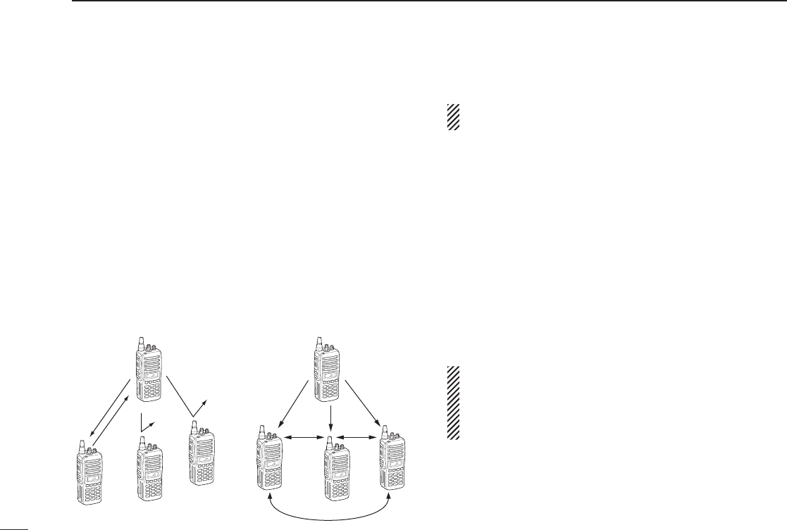
Selective calling Non-selective calling

13
3
BASIC OPERATION
D Transmitting notes
• Transmit inhibit function
The transceiver has several inhibit functions which restrict
transmission under the following conditions:
- The channel is in mute condition (‘Inaudible’ condition;
“” does not appear.)
- The channel is busy.
- Un-matched (or matched) CTCSS is received.
(Depending on the pre-setting.)
- The selected channel is a ‘receive only’ channel.
• Time-out timer
After continuous transmission for the pre-programmed time
period, the time-out timer is activated, causing the transceiv-
er to stop transmitting.
• Penalty timer
Once the time-out timer is activated, transmission is further
inhibited for a period determined by the penalty timer.
D TX code channel selection
If the transceiver has [TX Code CH Select] assigned to it,
indication can be toggled between the operating channel
number (or name) and TX code channel number (or name).
When the TX code channel number (or name) is displayed,
[UP]/[DOWN] selects the TX code channel.
TO SELECT A TX CHANNEL:
q Push [TX Code CH Select]— a TX code channel appears.
w Push [UP] or [DOWN] to select the desired TX code chan-
nel.
e Push [Call] (or [PTT] during MSK operation) to transmit
the selected TX code.
r Push [TX Code CH Select] again to return to the operat-
ing channel number indication.
FOR TX CODE CHANNEL TYPE:
If the transceiver has a [TX Code CH Up] or [TX Code CH
Down] key assignment, the programmed TX code channel
can be selected directly.

14
3BASIC OPERATION
D TX code number edit
(PMR or BIIS PMR operation only)
If the transceiver has [TX Code CH Select] or [TX Code
Enter] assigned to it, TX code contents can be edited within
the allowable digits.
TO EDIT A TX CODE VIA [TX CODE CH SELECT] KEY:
q Push [TX Code CH Select] to enter the TX code channel
selection mode.
• Select the desired channel using [UP] or [DOWN] if necessary.
w Push [TX Code CH Select] for 1 sec. to enter the TX code
edit mode.
e Push [TX Code CH Select] to select the desired digit to
be edited.
r Set the desired digit using [UP], [DOWN], [TX Code CH
Up], [TX Code CH Down] or 10-keypad.*
*Depending on version.
t Push [TX Code CH Select] to set the digit. The editable
digit will move to the right automatically.
• When the 10-keypad is used to set, the editable digit will move
to the right automatically without pushing [TX Code CH Select].
y Repeat r and t to input all allowable digits.
u Push [Call] or [PTT] to transmit the edited TX code.
TO EDIT A TX CODE VIA [TX CODE ENTER] KEY:
q Select the desired TX code channel via [TX Code CH Up]
or [TX Code CH Down].
w Push [TX Code Enter] to enter the TX code edit mode.
e Push [TX Code Enter] to select the desired digit to be
edited.
r Set the desired digit using [UP], [DOWN], [TX Code CH
Up] or [TX Code CH Down] or 10-keypad*.
*Depending on version.
t Push [TX Code Enter] to set the digit. The editable digit
will move to the right automatically.
• When the 10-keypad is used to set, the editable digit will move
to the right automatically without pushing [TX Code CH Select].
y Repeat r and t to input all allowable digits.
u Push [Call] or [PTT] to transmit the edited TX code.

15
3
BASIC OPERATION
D DTMF transmission
If the transceiver has [DTMF Autodial] assigned to it, the
automatic DTMF transmission function is available. Up to 8
DTMF channels are available.
TO SELECT A TX CODE:
q Push [DTMF Autodial]— a DTMF channel appears.
w Push [UP] or [DOWN] to select the desired DTMF chan-
nel.
e Push [DTMF Autodial] to transmit the DTMF code in the
selected DTMF channel.
■ User set mode
User set mode is accessed with [User Set Mode] and allows
you to set seldom-changed settings. In this case you can
“customize” the transceiver operation to suit your prefer-
ences and operating style.
Entering the user set mode:
q Push and hold [User Set Mode] to enter user set mode.
Push [User Set Mode] momentarily to select the item.
Then push [UP] or [DOWN] to set the desired level/condi-
tion.
• Available set mode functions are Backlight, Beep, SQL Level,
Mic Gain and Battery Voltage.
w Push and hold [User Set Mode] to exit user set mode.
■ Scrambler function
The voice scrambler function provides private communi-
cation between stations. The frequency inversion type is
equipped to all versions, moreover, the optional Rolling or
Non-rolling type can be available.
q Push [Scrambler] to turn the scrambler function ON.
• “ ” appears.
w Push [Scrambler] again to turn the scrambler function
OFF.
• “ ” disappears.
16
4BIIS OPERATION
■ Default setting
The following functions are assigned to each programmable
key as the default. However, the assigned function can be
changed by your dealer. Ask your dealer for details.
NOTE: [TX Code Enter] must be assigned to any key.
[P0]; Call : Push to transmit a 5-tone/BIIS call
when the selected channel is a
5-tone or MSK channel, respec-
tively.
[P1]; Digital : Push to select the call list ID/trans-
mit message, or to display the
receive message record for selec-
tion.
[P3]; TX Code Enter : Push to enter the direct ID code
edit mode for both 5-tone and
MSK.
[UP]/[DOWN]; CH Up/Down
: While in the standby condition,
selects the operating channel.
After pushing [Digital] or [TX Code
CH Select], selects call list or TX
code channel, respectively.
[MONITOR]; Moni(Audi): Push this key after the communica-
tion to send a ‘Clear down’ signal
during MSK channel operation.
[P2]/[RED]; Null : No function is assigned.
■ Receiving a call
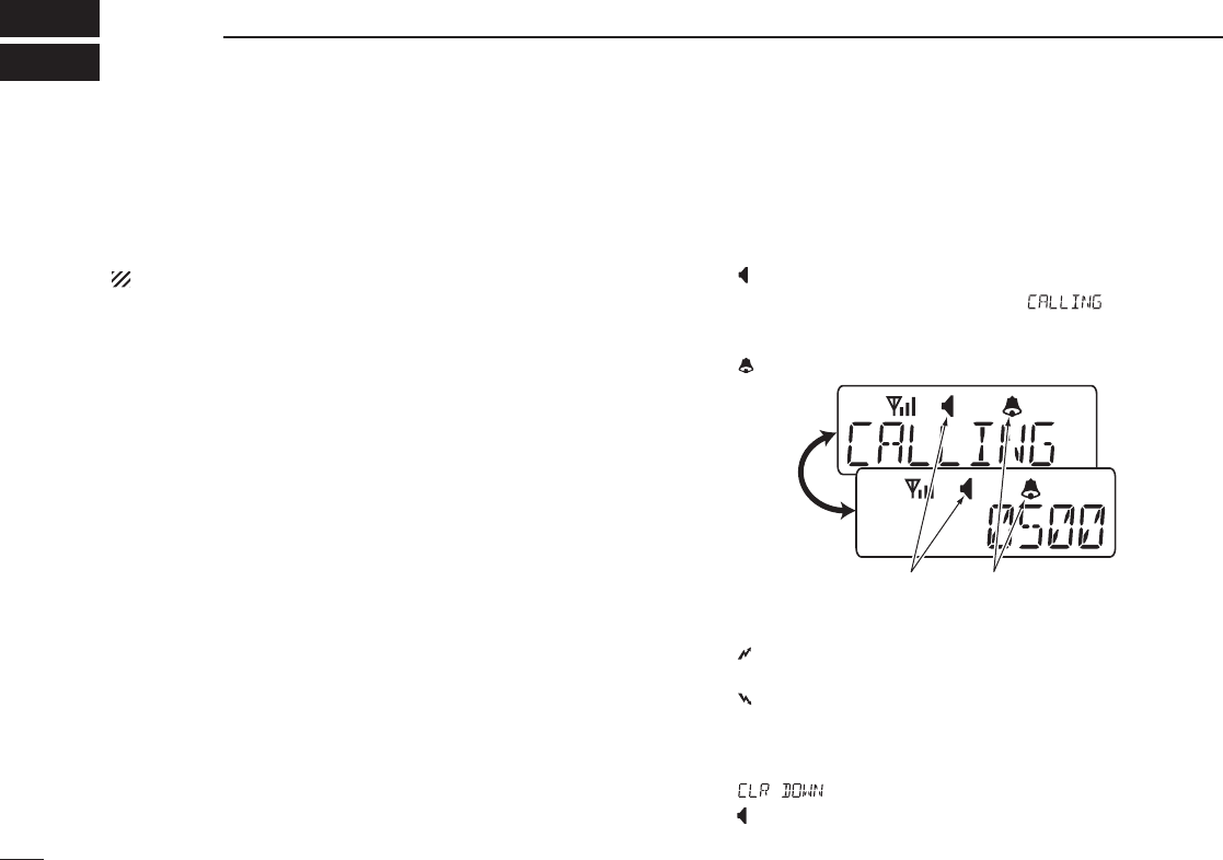
D Individual call
q When an individual call is received;
• Beeps sound.
• “ ” appears and the mute is released.
• The programmed text message (e.g.“ ”) and the call-
ing station ID (or text) is displayed alternately, depending on the
setting.
• “ ” appears or blinks depending on the setting.
w Push and hold [PTT], then speak into the microphone at
a normal voice level.
• “ ” indicator appears.
e Release [PTT] to return to receive.
• “ ” appears while receiving a signal.
r To finish the conversation, push [MONITOR] (Moni(Audi))
to send the ‘Clear down’ signal.
• Either station can send a ‘Clear down’ signal.
• “ ” is displayed for 2 sec. (approx.).
• “ ” disappears and the transceiver returns to the standby con-
dition.
Appears or blinksAppears
17
4
BIIS OPERATION
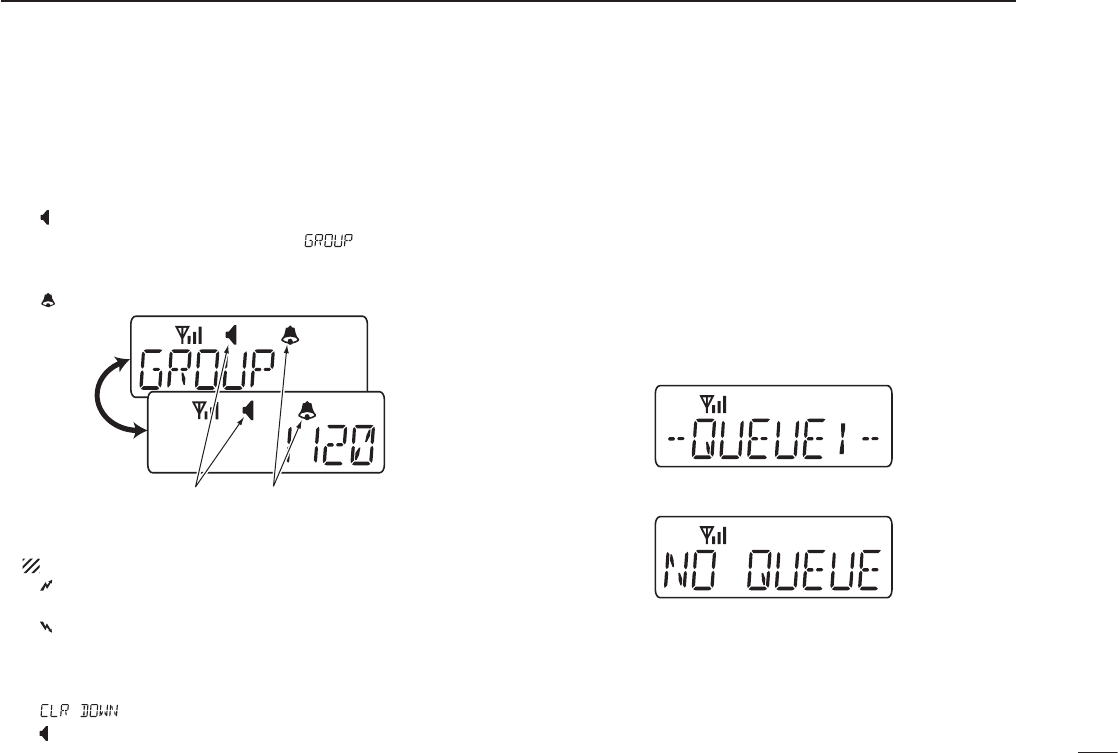
D Group call
q When a group call is received;
• Beeps sound.
• “ ” appears and the mute is released.
• The programmed text message (e.g.“ ”) and the calling
station ID (or text) is displayed alternately, depending on the
setting.
• “ ” appears or blinks depending on the setting.
w Push and hold [PTT], then speak into the microphone at
a normal voice level.
NOTE: Only one station is permitted to speak.
• “ ” appears.
e Release [PTT] to return to receive.
• “ ” appears while receiving a signal.
r To finish the conversation, push [MONITOR] (Moni(Audi))
to send the ‘Clear down’ signal.
• Either station can send a ‘Clear down’ signal.
• “ ” is displayed for 2 sec. (approx.)
• “ ” disappears and the transceiver returns to the standby con-
dition.
D Displaying the received call record
— Queue indication
The transceiver memorizes the calling station IDs for record.
Up to 3 calls can be memorized, and the oldest call record is
erased when a 4th call is received. However, once the trans-
ceiver is powered OFF, the all records are cleared.
q Push [P1] (Digital) for 1 sec.
• Displays following indication.
When a record is available
When no record is available
w Push [UP] or [DOWN] to select the desired call.
e Push [P1] (Digital) for 1 sec. again to return to the stand-
by condition.
• When no operation is performed for 30 sec., the transceiver
returns to the standby condition automatically.
Appears or blinksAppears
18
4BIIS OPERATION
■ Transmitting a call
Total of a 3 ways for code selection are available—selecting
the call code from memory, entering the call code from the
keypad and calling back from the queue channel record.
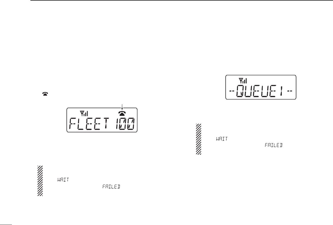
D Using call memory
q While in the standby condition, push [P1] (Digital) to enter
the call code memory channel selection mode.
• “ ” appears.
w Push [UP] or [DOWN] to select the desired call code.
e Push [P0] (Call) or [PTT]* to call.
*
PTT call can be made only when PTT call capability is permitted.
NOTE: When no answer back is received, the trans-
ceiver repeats the call 3 times (default) automatically,
and “ ” is displayed during each call. However, an
error beep sounds and “ ” is displayed when no
answer back is received after the calls.
r Push [PTT] to transmit; release to receive.
t Push [MONITOR] (Moni(Audi)) to send the ‘Clear down’
signal.
D Calling back from the queue channel
q
While in the standby condition, push [P1] (Digital) for 1 sec.
to enter the queue memory channel selection mode.
w Push [UP] or [DOWN] to select the desired record.
e Push [P0] (Call) or [PTT]* to call.
*
PTT call can be made only when PTT call capability is permitted.
NOTE: When no answer back is received, the trans-
ceiver repeats the call 3 times (default) automatically,
and “ ” is displayed during each call. However, an
error beep sounds and “ ” is displayed when
no answer back is received after the calls.
r Push [PTT] to transmit; release to receive.
t Push [MONITOR] (Moni(Audi)) to send the ‘Clear down’
signal.
Call code text is displayed.
Appears

19
4
BIIS OPERATION
D Direct code entry
q While in the standby condition, push [P3] (TX Code Enter)
to enter the TX code edit mode.
• Editable code digit blinks.
w Push [P3] (TX Code Enter) to select the desired digit to
be edited.
• Editable digit differs according to the setting.
e Set the desired digit using [CH Up]/[CH Down]/[TX Code
CH Up]/[TX Code CH Down] or 10-keypad.*
*Depending on version
r Push [P3] (TX Code Enter) to set the digit, then the edit-
able digit will move to the right automatically.
• When the 10-keypad is used to set, the editable digit will move
to the right automatically without pushing [P3] (TX Code Enter).
t Repeat e and r to input all allowable digits.
y Push [P0] (Call) or [PTT]* to call.
* PTT call can be made only when PTT call capability is permitted.
NOTE: When no answer back is received, the trans-
ceiver repeats the call 3 times (default) automatically,
and “ ” is displayed during each call. However, an
error beep sounds and “ ” is displayed when no
answer back is received after the calls.
u Push [PTT] to transmit; release to receive.
i Push [MONITOR] (Moni(Audi)) to send the ‘Clear down’
signal.
For your information
When the “UpDate” setting for the call code is enabled, the
set code is overwritten into the call code memory.
20
4BIIS OPERATION
■ Receiving a message
D Receiving a status message
q When a status message is received;
• Beeps sound.
• The calling station ID (or text) and the status message is dis-
played alternately, depending on the setting.
w Push [MONITOR] (Moni(Audi)) to return to the standby
condition.
NOTE: Only the calling station ID (or text) is displayed
(no message is displayed alternately) when the scroll
timer is set to ‘OFF.’ In this case, push [Status Up]/
[Status Down] to display the status message manually.
D Receiving an SDM
q When an SDM is received;
• Beeps sound.
• The calling station ID (or text) and the SDM is displayed alter-
nately, depending on the setting.
w When the received SDM includes more than 8 characters,
“” appears and the message scrolls automatically, when
the automatic scroll function is activated.
• Push [Status Up]/[Status Down] to scroll the message manually.
e Push [MONITOR] (Moni(Audi)) to return to the standby
condition.

21
4
BIIS OPERATION
D Received message selection
The transceiver memorizes the received messages for
record. Up to 6 messages for status and SDM, or 95 charac-
ter SDM’s can be memorized. The oldest message is erased
when the 7th message is received. However, once the trans-
ceiver is powered OFF, all messages are cleared.
q Push [P1] (Digital) for 1 sec.
• Displays queue memory.
w Push [P1] (Digital) momentarily.
• Displays message memory.
When a message is available
When no message is available
e Push [UP] or [DOWN] to select the desired message.
• When selecting the SDM that includes more than 8 characters,
“” appears and the message scrolls automatically, when the
automatic scroll function is activated.
• Push [Status Up]/[Status Down] to scroll the message manually.
r Push [P1] (Digital) for 1 sec. again to return to the stand-
by condition.
• When no operation is performed for 30 sec., the transceiver
returns to the standby condition automatically.

22
4BIIS OPERATION
■ Transmitting a status
D General
The status message can be selected with the programmed
text, and the message text is also displayed on the function
display of the called station.
Up to 24 status types (1 to 24) are available, and the status
messages 22 and 24 have designated meanings.
Status 22: Emergency*
Status 24: GPS request
*
The status 22 can also be used as a normal status message by
disabling the designated meaning. However, the status 24 is fixed.
The status call can be sent with both individual and group
calls.
D Transmitting a status
q While in the standby condition, push [P1] (Digital), then
push [UP] or [DOWN] to select the desired station/group
code.
w Push [P1] (Digital) again, then push [UP] or [DOWN] to
select the desired status message.
Or, you can select the desired status message using
[Status Up]/[Status Down] key directly.
e Push [P0] (Call) or [PTT]* to transmit the status message
to the selected station/group.
*PTT call can be made only when PTT call capability is permitted.
• 2 beeps will sound and the transceiver returns to the standby
condition automatically when the transmission is successful.
Status message is displayed.

23
4
BIIS OPERATION
■ Transmitting an SDM
D General
The short data message, SDM, can be sent to an individual
station or group stations. Also, 8 SDM memory channels are
available and the messages can be edited via PC program-
ming.
D Transmitting an SDM
q While in the standby condition, push [P1] (Digital), then
push [UP] or [DOWN] to select the desired station/group
code.
w Push [P1] (Digital) again, then push [UP] or [DOWN] to
select the desired SDM.
Or, you can select the desired SDM using [Status Up]/
[Status Down] key directly.
e Push [P0] (Call) or [PTT]* to transmit the SDM to the
selected station/group.
*
PTT call can be made only when PTT call capability is permitted.
• 2 beeps will sound and the transceiver returns to the standby
condition automatically when the transmission is successful.
SDM is displayed.
24
4BIIS OPERATION
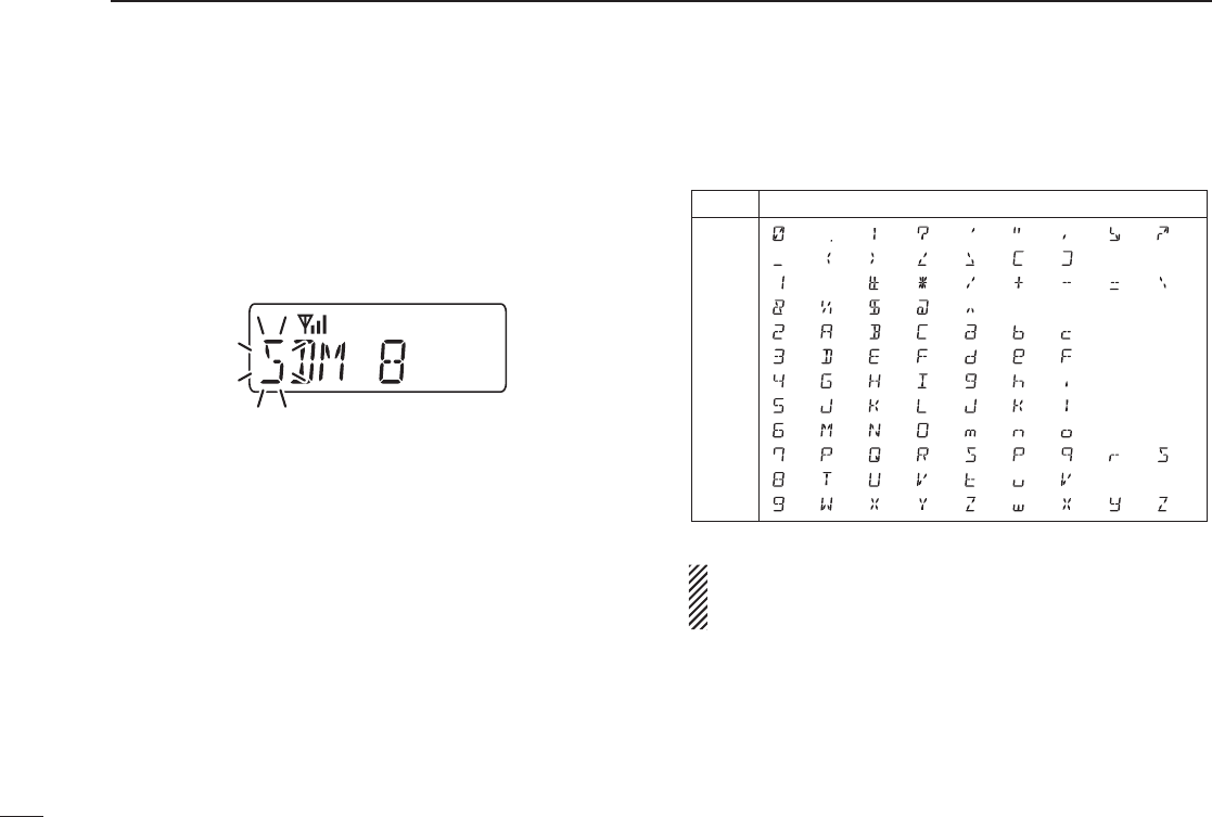
D Programming an SDM memory
(10-keypad version is required)
q During standby condition, push [P1] (Digital) twice, then
push [UP] or [DOWN] to select the desired SDM to be
edited.
w Push [M] or [#] to enter the message editing condition.
• The rst character blinks when [#] is pushed, the last character
blinks when [M] is pushed as below.
e Push the appropriate digit key, [0] to [9], to enter the
desired character.
• See the table at right for the available characters.
• Pushing [UP] also enters space, pushing [DOWN] deletes the
selected character.
r Push [#] to move the cursor to the right, push [M] to move
the cursor to the left.
t Repeat steps e and r to set the desired text message.
y Push [P1] (Digital) for 1 sec. to overwrite the set content
into the memory.
• Push [P1] (Digital) momentarily to cancel the editing and return
to the original message indication.
• Available characters
NOTE: Once the pre-programmed character including a
decimal point is rewrote with the 10-keypad, the decimal
point cannot be displayed again.
Key
[0]
[1]
[2]
[3]
[4]
[5]
[6]
[7]
[8]
[9]
Characters
(0)
(1)
(2)
(3)
(4)
(5)
(6)
(7)
(8)
(9)
(.)
(Space)
(A)
(D)
(G)
(J)
(M)
(P)
(T)
(W)
(!)
(#)
(B)
(E)
(H)
(K)
(N)
(Q)
(U)
(X)
(?)
(�)
(C)
(F)
(I)
(L)
(O)
(R)
(V)
(Y)
(')
(/)
(a)
(d)
(g)
(j)
(m)
(S)
(t)
(Z)
(")
(+)
(b)
(e)
(h)
(k)
(n)
(p)
(u)
(w)
(,)
(Ð)
(c)
(f)
(i)
(l)
(o)
(q)
(v)
(x)
(;)
(=)
(r)
(y)
(:)
(_) (() ()) (<) (>) ([) (])
(/)
(&) (%) ($) (@) (^)
(s)
(z)

25
4
BIIS OPERATION
■ Position data transmission
When the optional cable and a GPS receiver is connected to
the transceiver, the position (longitude and latitude) data can
be transmitted automatically.
Ask your dealer or system operator for connection details.
The position data is transmitted when;
• Status 24 message is received
*When the status 24 message, GPS request, is received.
• Fully automatic
When automatic position transmission is enabled, send
the position data according to ‘Time Marker’ and ‘Interval
Timer’ settings.
• PTT is released
When ‘Send with Logoff’ is enabled.
- Set the ‘Log-In/Off’ item as ‘L-OFF.’
• After sending a status message
When ‘Send with Status’ is enabled.
• After sending an SDM
When ‘Send with SDM’ is enabled.
• After sending status 22 (Emergency)
When ‘Send with Emergency’ is enabled.
■ Printer connection
When the optional cable is connected to the transceiver, a
printer can be connected to print out the received SDM con-
tent and the ID of the station who sent the message.
Ask your dealer or system operator for connection details.
■ Digital ANI
The own ID can be transmitted each time the PTT is pushed
(log-in) or released (log-off) during individual or group call
communications.
By receiving the ANI, the communication log can be record-
ed when using a PC dispatch application.
In addition, when using the ANI with log-in, the PTT side
tone function can be used to inform you that the ID is sent
and voice communication can be performed.
26
4BIIS OPERATION
■ Auto emergency transmission
When [Emergency Single (Silent)] or [Emergency Repeat
(Silent)] is pushed, an emergency signal is automatically
transmitted for the specified time period.
The status 22 (Emergency) is sent to the selected ID station,
and the position data is transmitted after the emergency sig-
nal when a GPS receiver is connected to the transceiver.
The emergency transmission is performed on the emer-
gency channel, however, when no emergency channel is
specified, the signal is transmitted on the previously selected
channel.
There is no change in the function display or beep emission
during automatic emergency transmission.
■ Stun function
When the specified ID, set as a killer ID, is received, the stun
function is activated.
When the killer ID is received, the transceiver switches to
the password required condition. Entering of the password
via the keypad is necessary to operate the transceiver again
in this case.
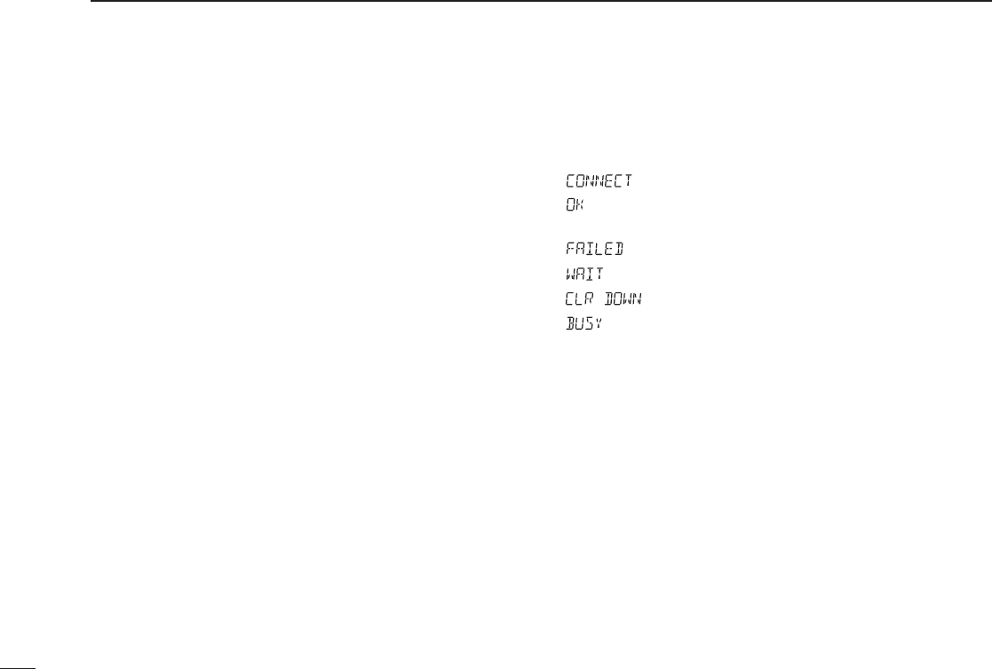
■ BIIS indication
The following indications are available for the BIIS operation
on an MSK channel.
: Individual/group call is successful.
: Message (status or SDM) transmission is suc-
cessful.
: No answer back is received.
: Appears during retry of the call (2nd call).
: End the communication.
: Operating channel is in the busy condition.
■ Priority A channel selection
When one of the following operations is performed, the
transceiver selects the Priority A channel automatically.
Priority A is selected when;
• Clear down signal is received/transmitted
- Set the ‘Move to PrioA CH’ item as ‘Clear down.’
• Turning the power ON
The Priority A channel is selected each time the trans-
ceiver power is turned ON.
• Status call
The Priority A channel is selected when transmitting a
status call.
- Enable the ‘Send Status on PrioA CH’ item in the MSK
configuration.

27
4
BIIS OPERATION
■ Man Down Emergency Call
The optional UT-124 m a n d o w n u n i t is required for this func-
tion.
The man down emergency call function transmits an emer-
gency call automatically, when the transceiver has been left
in a horizontal position.
This function can be performed for both 5-tone and MSK
channels.
After the emergency call, the transceiver performs transmis-
sion and reception alternately with the following conditions:
- Transmits the microphone signals.
- Receives the signal and emits audio.
When the emergency reset signal is received, the function is
cancelled.
IMPORTANT: Set an emergency channel individually, to
provide certain emergency call operation is recommended.

28
5MDC 1200 OPERATION
■ MDC 1200 system operation
The MDC 1200 signaling system enhances your transceiver’s
capabilities. It allows PTT ID*, Selective Calling, Call Alert,
Radio Check, Messaging and Emergency signaling. Also,
the dispatcher can stun and revive transceivers on the sys-
tem.
An additional feature of MDC 1200 found in Icom transceiv-
ers is called aliasing. Each transceiver on the system has
a unique ID number. Aliasing allows the substitution of an
alphanumeric name for this ID number. For transmit, you can
use this alias to select a transceiver to call. For receive, the
alias of the calling station is displayed instead of the ID.
The following section describes the operation of the MDC
1200 features using the alias function. The Selective Call,
Call Alert and Radio Check features can also be used with
direct ID code entry from the transceiver keypad. (p. 32)
Please note that your dealer has set one of the programma-
ble keys (P0, P1, P2, or P3) for MDC 1200 operation.
*When [PTT] is pushed or released, self ID is transmitted.
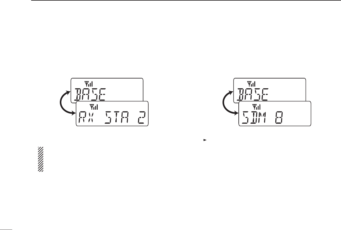
■ Transmitting a call
D Transmitting a Selective Call
Selective calling allows you to make a call to a specific sta-
tion or to a particular group. Other MDC 1200 transceivers
on the channel will not receive a selective call that does not
match their station or group ID’s.
q Push [MDC Call] to enter the MDC menu selection mode.
• Or push [MDC Selcall] to enter the transceiver alias selection
mode. In this case, skip step w.
w Push [MDC Call] again to enter the transceiver alias
selection mode.
e Select the desired alias using [CH Up], [CH Down], [MDC
Up] or [MDC Down].
r Push and hold [PTT] to transmit the selective call to the
selected station, then speak into the microphone.
t Release [PTT] to receive.
SELL CALL is displayed.

29
5
MDC 1200 OPERATION
D Transmitting a Call Alert
Call Alert allows you to notify another user who may be away
from the transceiver that you want to talk.
q Push [MDC Call] to enter the MDC menu selection mode.
• Or push [MDC CallAlert] to enter the transceiver alias selection
mode. In this case, skip steps w and e.
w Select “CALALERT” using [CH Up], [CH Down], [MDC Up]
or [MDC Down].
e Push [MDC Call] again to enter the transceiver alias
selection mode.
r Select the desired alias using [CH Up], [CH Down], [MDC
Up] or [MDC Down].
t Push [PTT] to transmit the call alert to the selected sta-
tion.
• “CA CALL” is displayed.
y Release [PTT].
• “CA OK” is displayed if the targeted station received the alert.
• “CA FAIL” is displayed if the targeted station does not send an
acknowledgement.
u After a specified time period has passed, the transceiver
will return to receive.
D Transmitting a Radio Check Call
Radio check call allows you to determine whether another
transceiver is turned on, within range and on channel with-
out requiring any action from the targeted station user.
q Push [MDC Call] to enter the MDC menu selection mode.
w Select “RADIOCHK” using [CH Up], [CH Down], [MDC Up]
or [MDC Down].
e Push [MDC Call] again to enter the transceiver alias
selection mode.
r Select the desired alias using [CH Up], [CH Down], [MDC
Up] or [MDC Down].
t Push [PTT] to transmit the radio check call to the selected
station.
• “RDO CHK” is displayed.
y Release [PTT].
• “CHK ACK” is displayed if the targeted station is turned ON, on
channel and within range.
• “CHK FAIL” is displayed if the targeted station does not send an
acknowledgement.
u After a specified time period has passed, the transceiver
will return to receive.

30
5MDC 1200 OPERATION
D Transmitting a Status Message
Status Messaging allows you to send a pre-programmed
status message to the dispatcher. There are 16 status codes
that can be sent. In addition, the dispatcher can send an
MDC 1200 signal that causes the transceiver to automati-
cally transmit its current status.
q Push [MDC Call] to enter the MDC menu selection mode.
w Select “STATUS” using [CH Up], [CH Down], [MDC Up] or
[MDC Down].
e Push [MDC Call] again to enter the status message selec-
tion mode.
r Select the desired status message using [CH Up], [CH
Down], [MDC Up] or [MDC Down].
t Push [PTT] to transmit the status message to the dis-
patcher.
• “STAT TX” is displayed.
y Release [PTT].
• “STAT OK” is displayed.
• “STA FAIL” is displayed if there is no acknowledgment from the
dispatcher.
u After a specified time period has passed, the transceiver
will return to receive.
Pre-programmed status
message is displayed.

31
5
MDC 1200 OPERATION
D Transmitting a Message
The transceiver can send a pre-programmed message to
the dispatcher. There are 16 messages that can be sent on
a channel.
q Push [MDC Call] to enter the MDC menu selection mode.
w Select “MSG” using [CH Up], [CH Down], [MDC Up] or
[MDC Down].
e Push [MDC Call] again to enter the pre-programmed mes-
sage selection mode.
r Select the desired message using [CH Up], [CH Down],
[MDC Up] or [MDC Down].
t Push [PTT] to transmit the message to the dispatcher.
• “MSG TX” is displayed.
y Release [PTT].
• “MSG OK” is displayed.
• “MSG FAIL” is displayed if there is no acknowledgment from the
dispatcher.
u After a specified time period has passed, the transceiver
will return to receive.
D Emergency Calls
The MDC 1200 Emergency feature can be accessed using
the [MDC Emg] key (p. 10). The optional UT-124 man d o w n
unit can also activate this feature. The transceiver will
repeatedly send an Emergency MDC 1200 command to the
dispatcher for a programmed length of time until it receives
an acknowledgement signal.
The emergency call can be transmitted without a beep emis-
sion and LCD indication change depends on the setting.
With MDC 1200 Emergency, the transceiver can also be
programmed to keep the microphone open during an emer-
gency call, allowing monitoring of the situation.
Ask your dealer for details.
D Stun and Revive
The dispatcher can send MDC 1200 signals that will stun or
revive your transceiver. If a Stun command is received that
matches your station ID, the transceiver will display “SORRY”
and you can not receive or transmit. When a Revive com-
mand is received that matches your station ID, normal oper-
ation is restored.
Pre-programmed message is displayed.
32
5MDC 1200 OPERATION
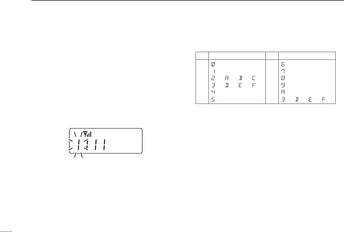
D Programming station ID code
(10-keypad version is required)
If your transceiver is equipped with a 10-keypad, you can
enter a station ID code from the keypad for the Selective
Call, Call Alert or Radio Check Call functions.
q Push [MDC Call] to enter the MDC menu selection mode.
w Select “SELCALL”, “RADIOCHK” or “CALALERT” using
[CH Up], [CH Down], [MDC Up] or [MDC Down].
e Push [MDC Call] again to enter the transceiver alias
selection mode.
r Push any key of the keypad to enter the ID code program-
ming condition.
• The rst digit blinks as below.
t Push [UP] to move the cursor to the right, push [DOWN]
to move the cursor to the left.
y When the last digit of the desired ID has been entered,
push [PTT] to transmit.
• Available characters
Key CharactersKey
[0]
[1]
[2]
[3]
[4]
[5]
Characters
(0)
(1)
(2)
(3)
(4)
(5)
(6)
(7)
(8)
(9)
(A)
(D)
(B)
(E)
(C)
(F)
[6]
[7]
[8]
[9]
[M]
[#] (3) (D) (E) (F)
(A)
33
5
MDC 1200 OPERATION
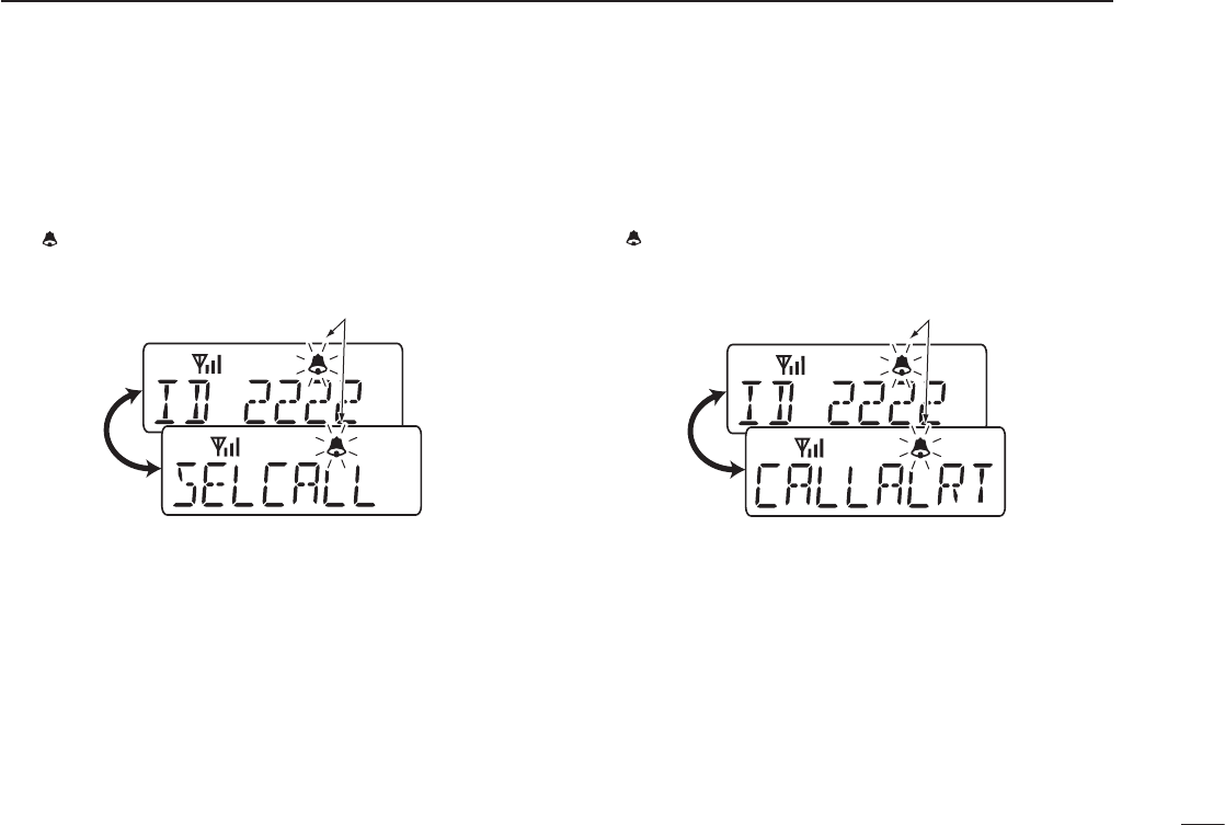
■ Receiving a call
D Receiving a Selective Call
q When an individual call is received;
• Beeps sound.
• “ ” blinks.
• The calling station ID (or alias) and “SELCALL” are displayed
alternately.
w Push and hold [PTT] and speak into the microphone.
e Release [PTT] to receive a response.
D Receiving a Call Alert
q When a Call Alert is received;
• Beeps sound.
• “ ” blinks.
• The calling station ID (or alias) and “CALLALRT” are displayed
alternately.
w Push and hold [PTT] and speak into the microphone.
e Release [PTT] to receive a response.
Blinks
Blinks
34
6OPTIONAL UNIT INSTALLATION
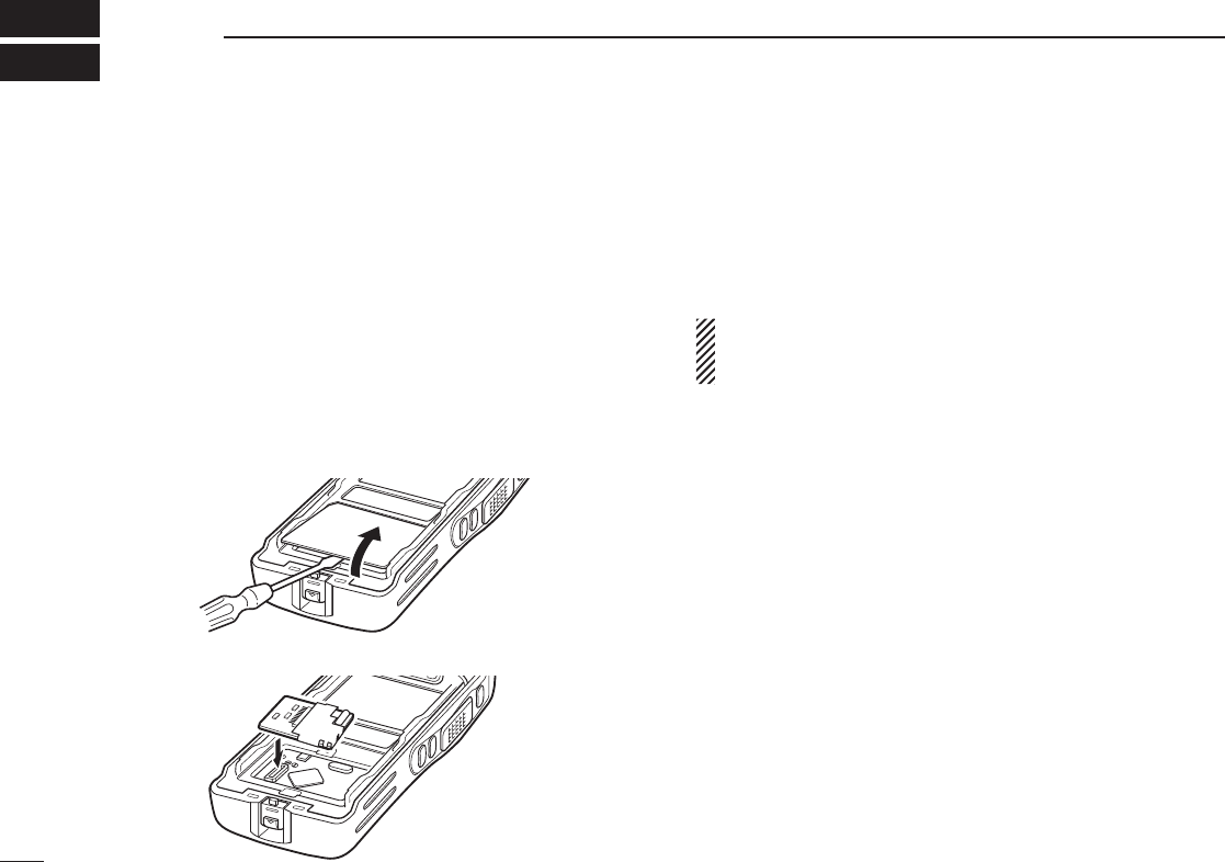
■ Optional unit installation
Install the optional unit as follows:
q Rotate [VOL] to turn the power OFF, and remove the bat-
tery pack. (p. 2)
w Remove the unit cover.
NOTE: Use a flat head screw driver or a similar flat instrument,
and insert into the hollow of the chassis, then lift and take away
the unit cover.
Use the supplied spare unit cover! Do not use the cover that
has been removed once. Water or dust may get into the trans-
ceiver because the cover may be bent or has lost it’s adhesion.
This may result in the transceiver being damaged.
e Install the unit as shown below.
r Replace the unit cover and the battery pack, then rotate
[VOL] to turn the power ON.
NOTE: The optional UT-109/UT-110 scrambler units
require some PC board modifications. Please refer to the
additional installation as shown on p. 35.
*This illustration is
described with
the UT-109.
35
6
OPTIONAL UNIT INSTALLATION
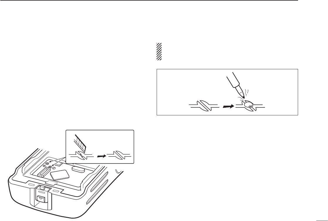
■ UT-109 and UT-110 installation
The following PC board modification is required when install-
ing the optional UT-109 or UT-110:
q Rotate [VOL] to turn the power OFF, and remove the bat-
tery pack. (p. 2)
w Remove the unit cover as shown on p. 34 (Optional unit
installation).
e Cut the pattern on the PCB at the TX mic circuit (C) and
RX AF circuit (F) as shown below.
r Install the scrambler unit as described in the Optional unit
installation (p. 34).
t Replace the unit cover and the battery pack, then rotate
[VOL] to turn the power ON.
NOTE: When uninstalling the scrambler unit
Be sure to re-solder the disconnected points at left, other-
wise no TX modulation or AF output is available.

36
7BATTERY CHARGING
■ Caution
Misuse of Lithium-Ion batteries may result in the fol-
lowing hazards: smoke, fire, or the battery may rupture.
Misuse can also cause damage to the battery or degra-
dation of battery performance.
• R DANGER! Use and charge only specified Icom battery
packs with Icom radios or Icom charger. Only Icom battery
packs are tested and approved for use and charge with
Icom radios or Icom charger. Using third-party or coun-
terfeit battery packs or charger may cause smoke, fire, or
cause the battery to burst.
D Battery caution
• R DANGER! DO NOT hammer or otherwise impact the
battery. Do not use the battery if it has been severely
impacted or dropped, or if the battery has been subjected
to heavy pressure. Battery damage may not be visible on
the outside of the case. Even if the surface of the battery
does not show cracks or any other damage, the cells inside
the battery may rupture or catch fire.
• R DANGER! NEVER use or leave battery packs in areas
with temperatures above +60˚C (+140˚F). High tempera-
ture buildup in the battery, such as could occur near fires
or stoves, inside a sun heated car, or in direct sunlight
may cause the battery to rupture or catch fire. Excessive
temperatures may also degrade battery performance or
shorten battery life.
• R DANGER! DO NOT expose the battery to rain, snow,
seawater, or any other liquids. Never charge or use a wet
battery. If the battery gets wet, be sure to wipe it dry before
using. The battery is not waterproof.
• R DANGER! NEVER incinerate used battery packs since
internal battery gas may cause them to rupture, or may
cause an explosion.
• R DANGER! NEVER solder the battery terminals or
NEVER modify the battery pack. This may cause heat gen-
eration, and the battery may rupture, emit smoke or catch
fire.
• R DANGER! Use the battery only with the transceiver for
which it is specified. Never use a battery with any other
equipment, or for any purpose that is not specified in this
instruction manual.
• R DANGER! If fluid from inside the battery gets in your
eyes, blindness can result. Rinse your eyes with clean
water, without rubbing them, and see a doctor immediately.

37
7
BATTERY CHARGING
• WARNING! Immediately stop using the battery if it emits
an abnormal odor, heats up, or is discolored or deformed. If
any of these conditions occur, contact your Icom dealer or
distributor.
• WARNING! Immediately wash, using clean water, any part
of the body that comes into contact with fluid from inside
the battery.
• WARNING! NEVER put the battery in a microwave oven,
high-pressure container, or in an induction heating cooker.
This could cause a fire, overheating, or cause the battery
to rupture.
• CAUTION! Always use the battery within the specified tem-
perature range for the transceiver (–30˚C to +60˚C; –22˚F
to +140˚F) and the battery itself (–20˚C to +60˚C; –4˚F to
+140˚F). Using the battery out of its specified temperature
range will reduce the battery’s performance and battery life.
• CAUTION! Shorter battery life could occur if the battery is
left fully charged, completely discharged, or in an exces-
sive temperature environment (above +50˚C; +122˚F)
for an extended period of time. If the battery must be left
unused for a long time, it must be detached from the radio
after discharging. You may use the battery until the remain-
ing capacity is about half, then keep it safely in a cool dry
place with the temperature range as below:
–20˚C to +50˚C (–4˚F to +122˚F) (within a month)
–20˚C to +35˚C (–4˚F to +95˚F) (within three months)
–20˚C to +20˚C (–4˚F to +68˚F) (within a year)
D Charging caution
• R DANGER! NEVER charge the battery pack in areas with
extremely high temperatures, such as near fires or stoves,
inside a sun heated car, or in direct sunlight. In such envi-
ronments, the safety/protection circuit in the battery will
activate, causing the battery to stop charging.
• WARNING! NEVER charge or leave the battery in the bat-
tery charger beyond the specified time for charging. If the
battery is not completely charged by the specified time,
stop charging and remove the battery from the battery
charger. Continuing to charge the battery beyond the speci-
fied time limit may cause a fire, overheating, or the battery
may rupture.
• WARNING! NEVER insert the transceiver (battery attached
to the transceiver) into the charger if it is wet or soiled. This
could corrode the battery charger terminals or damage the
charger. The charger is not waterproof.
• CAUTION! NEVER charge the battery outside of the speci-
fied temperature range: BC-160 (0˚C to +40˚C; +32˚F to
+104˚F). Icom recommends charging the battery at +20˚
C (+68˚F). The battery may heat up or rupture if charged
out of the specified temperature range. Additionally, battery
performance or battery life may be reduced.
38
7BATTERY CHARGING
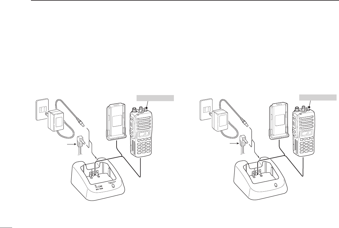
■ Optional battery chargers
D Rapid charging with the BC-160
The optional BC-160 provides rapid charging of the Li-Ion
battery pack.
• An AC adapter (may be supplied with BC-160 depending
on version) or the DC power cable (OPC-515L/CP-17L) is
additionally required.
D Regular charging with the BC-171
The optional BC-171 provides regular charging of the Li-Ion
battery pack.
• An AC adapter (may be supplied with BC-171 depending
on version) or the DC power cable (OPC-515L/CP-17L) is
additionally required.
AC adapter
(Not supplied with
some versions.)
Optional OPC-515L
(for 13.8 V power
source) or CP-17L
(for 12 V cigarette
lighter socket) can
be used instead of
the AC adapter.
BATTERY
PACK
TRANSCEIVER
Turn power OFF
AC adapter
(Not supplied with
some versions.)
BATTERY
PACK
TRANSCEIVER
Turn power OFF
Optional OPC-515L
(for 13.8 V power
source) or CP-17L
(for 12 V cigarette
lighter socket) can
be used instead of
the AC adapter.
39
7
BATTERY CHARGING
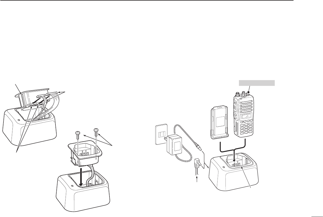
D AD-106 installation
q Install the AD-106 desktop charger adapter into the hold-
er space of the BC-119N/BC-121N.
w Connect the plugs of the BC-119N/BC-121N to the
AD-106 desktop charger adapter with the connector,
then install the adapter into the charger with the supplied
screws.
D Rapid charging with the BC-119N+AD-106
The optional BC-119N provides rapid charging of battery
packs. The following items are additionally required.
• AD-106 charger adapter
• An AC adapter (may be supplied with BC-119N depending
on version) or the DC power cable (OPC-515L/CP-17L).
AD-106 charger
adapter is installed
in BC-119N.
AC adapter
(Not supplied with
some versions.)
Optional OPC-515L (for 13.8 V
power source) or CP-17L (for
12 V cigarette lighter socket)
can be used instead of the AC
adapter.
TRANSCEIVER
BATTERY
PACK
Turn power OFF
Screws supplied
with the charger
adapter
AD-106
Connectors
Plugs
q
w
40
7BATTERY CHARGING
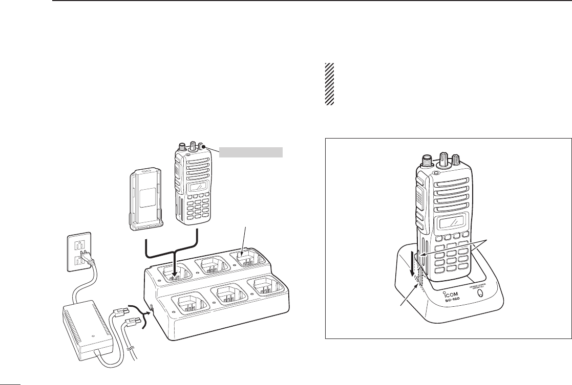
D Rapid charging with the BC-121N+AD-106
The optional BC-121N allows up to 6 battery packs to be
charged simultaneously. The following items are additionally
required.
• Six AD-106 charger adapters
• An AC adapter (BC-157) or the DC power cable (OPC-656)
IMPORTANT: Battery charging
Ensure the guide lobes on the battery pack are correctly
aligned with the guide rails inside the charger adapter.
(This illustration is described with the BC-160.)
AD-106 charger
adapters are installed
in each slot.
DC power cable (OPC-656)
(Connect with the DC power supply;
13.8 V/at least 7 A)
AC adapter
(Purchased
separately)
TRANSCEIVER
BATTERY
PACK
Turn power OFF
Guide rail
Lobes
41
8
BATTERY CASE
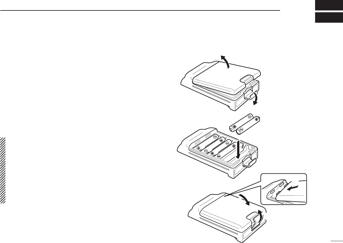
■ Optional battery case (BP-240)
When using the optional battery case, install 6 × AAA (LR03)
size alkaline batteries as illustrated at right.
q Unhook the battery cover release hook (q), and open the
cover in the direction of the arrow (w). (Fig.1)
w Then, install 6 × AAA (LR03) size alkaline batteries.
(Fig.2)
• Install the alkaline batteries only.
• Be sure to observe the correct polarity.
e Fit the cover in the direction of the arrow (e), then close
(r). And hook the battery cover release hook until it
makes a ‘click’ sound (t). (Fig.3)
CAUTION:
• When installing batteries, make sure they are all the
same brand, type and capacity. Also, do not mix new
and old batteries together.
• Keep battery contacts clean. It’s a good idea to clean
battery terminals once a week.
• Never incinerate used battery cells since internal battery
gas may cause them to rupture.
•
Never expose a detached battery case to water. If the bat-
tery case gets wet, be sure to wipe it dry before using it.
q
BP-240
w
Fig.1
Fig.2
Fig.3
e
r
t
42
9SWIVEL BELT CLIP
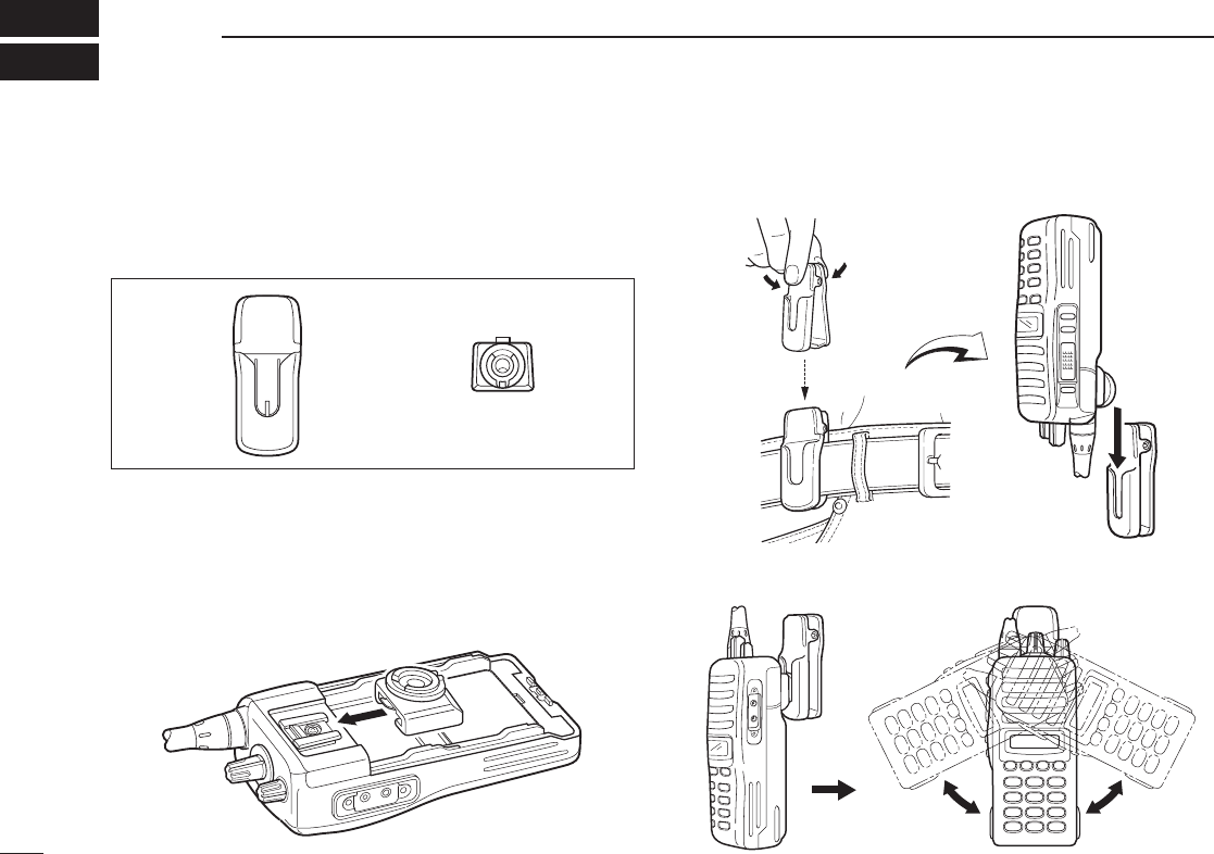
■ MB-93 contents
Qty.
q Belt clip ........................................................................... 1
w Base clip ......................................................................... 1
■ To attach
q Release the battery pack if it is attached. (p. 2)
w Slide the base clip in the direction of the arrow until the
base clip is locked and makes a ‘click’ sound.
e Clip the belt clip to a part of your belt. And insert the
transceiver into the belt clip until the base clip inserted
fully into the groove.
r Once the transceiver is locked in place, it swivels as illus-
trated below.
q w
43
9
SWIVEL BELT CLIP
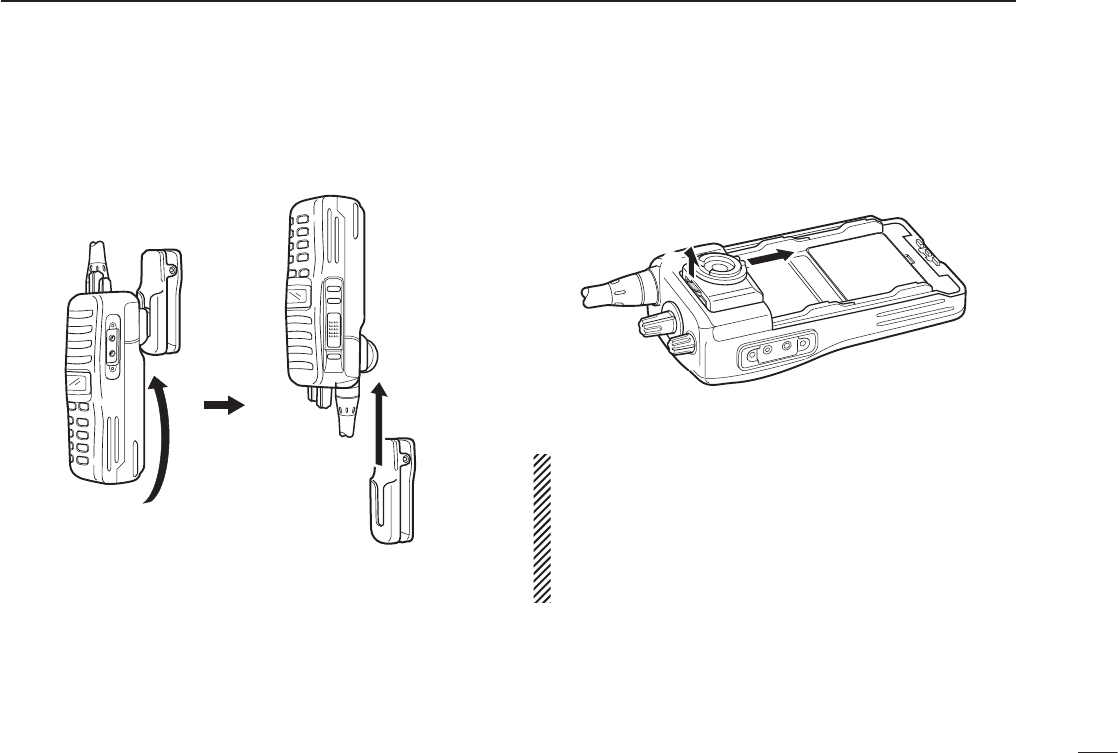
■ To detach
q Turn the transceiver upside down in the direction of the
arrow and pull out from the belt clip.
w Release the battery pack if it is attached. (p. 2)
e Pinch the clip (q), and slide the base clip in the direction
of the arrow (w).
CAUTION:
HOLD THE TRANSCEIVER TIGHTLY, WHEN HANGING
OR DETACHING THE TRANSCEIVER FROM THE BELT
CLIP.
Otherwise the transceiver may not be attached to the
holder or swivel properly if the transceiver is accidentally
dropped and the base clip is scratched or damaged.
qw

44
10 OPTIONS
D BATTERY PACK
Battery packs Voltage Capacity Battry life*1
BP-230N 7.4 V 950 mAh (min.)
980 mAh (typ.) 6.5 hrs.
BP-232N 7.4 V 1800 mAh (min.)
2000 mAh (typ.) 13.25 hrs.
BP-232H 7.4 V 2250 mAh (min.)
2350 mAh (typ.) 17.5 hrs.
BP-240 Battery case for AAA (LR03)
× 6 alkaline batteries —*2
*1 Operating periods are calculated under the following conditions;
TX : RX : standby = 5 : 5 : 90
*2 Operating period depends on the alkaline cells used.
D CHARGERS
• BC-119N d e s k t o p c h a r g e r + AD-106 c h a r g e r a d a p t e r
+ BC-145S a c a d a p t e r
For rapid charging of battery packs. An AC adapter is supplied
with the charger depending on versions.
Charging time: approx. 3.5 hours when BP-232H is attached.
• BC-121N m u l t i -c h a r g e r + AD-106 c h a r g e r a d a p t e r (6 pcs.)
+ BC-157S a c a d a p t e r
For rapid charging of up to 6 battery packs (six AD-106’s are re-
quired) simultaneously. An AC adapter should be purchased sep-
arately.
Charging time: approx. 3.5 hours when BP-232H is attached.
• BC-160 d e s k t o p c h a r g e r + BC-145S a c a d a p t e r
For rapid charging of battery packs. An AC adapter is supplied
with the charger depending on versions.
Charging time: approx. 3.5 hours when BP-232H is attached.
• BC-171 d e s k t o p c h a r g e r + BC-147S a c a d a p t e r
For regular charging of battery packs. We recommend that the
BP-230H charging. An AC adapter is supplied with the charger de-
pending on versions.
Charging time: approx. 11.5 hours when BP-232H is attached.
approx. 4 hours when BP-230 is attached.
D BELT CLIPS
• MB-93 s w i v e l b e lt c l i p
• MB-94 b e lt c l i p
Exclusive alligator-type belt clip.
• MB-96N/96F l e at h e r b e lt h a n g e r
D OPTIONAL UNITS
• UT-108 d t m f d e c o d e r u n i t
Provides pager and code squelch capabilities.
• UT-109 (#02)/UT-110 (#02) s c r a m b l e r u n i t s
Non-rolling type (UT-109)/Rolling type (UT-110) voice scrambler
unit provides higher communication security.
• UT-124 m a n d o w n u n i t
Provides a measure of safety when working in a hazardous envi-
ronment, etc.

45
10
OPTIONS
D DC CABLES
• CP-17L c i g a r e t t e l i g h t e r c a b l e
Allows charging of the battery pack through a 12 V cigarette lighter
socket. (For BC-119N)
• OPC-515L/OPC-656 d c p o w e r c a b l e s
Allows charging of the battery pack using a 13.8 V power source
instead of the AC adapter.
OPC-515L: For BC-119N
OPC-656 : For BC-121N
D OTHER OPTIONS
• SP-13 e a r p h o n e
Provides clear receive audio in noisy environment.
• HM-158L s p e a k e r -m i c r o p h o n e
Compact and durable body with screw-type connector.
• HM-159L s p e a k e r -m i c r o p h o n e
Full size durable speaker microphone.
• HM-153L s p e a k e r -m i c r o p h o n e
Durable earphone-microphone with revolving clip.
• HM-166L s p e a k e r -m i c r o p h o n e
Light-weight earphone microphone with revolving clip.
• HS-94/HS-95/HS-97 h e a d s e t + VS-1L v o x /p t t c a s e
HS-94: Ear-hook type
HS-95: Neck-arm type
HS-97: Throat microphone
VS-1L: VOX/PTT switch box for hands-free operation, etc.
• MB-130 v e h i c l e c h a r g e r b r a c k e t
Vehicle mounting bracket for BC-160 battery charger.
D ANTENNAS
• FA-SC56VS/FA-SC57VS/FA-SC73US s t u b b y a n t e n n a s
Shorter VHF or UHF antennas.
FA-SC56VS : 150–162 MHz
FA-SC57VS : 160–174 MHz
FA-SC73US : 450–490 MHz
• FA-SC25V/FA-SC55V
FA-SC25U/FA-SC57U/FA-SC72U f l e x i b l e a n t e n n a s
VHF or UHF antennas.
FA-SC25V : 136–150 MHz
FA-SC55V : 150–174 MHz
FA-SC25U : 400–430 MHz
FA-SC57U : 430–470 MHz
FA-SC72U : 470–520 MHz
• FA-SC61VC/FA-SC61UC c u t a n t e n n a s
FA-SC61VC : 136–174 MHz
FA-SC61UC : 380–520 MHz
Approved Icom optional equipment is designed for optimal perfor-
mance when used with an Icom transceiver.
Icom is not responsible for the destruction or damage to an Icom
transceiver in the event the Icom transceiver is used with equipment
that is not manufactured or approved by Icom.
Some options may not available in some countries. Please ask your
dealer for details.
46
11 SAFETY TRAINING INFORMATION
Your Icom radio generates RF electromagnetic
energy during transmit mode. This radio is de-
signed for and classified as “Occupational Use
Only”, meaning it must be used only during the
course of employment by individuals aware of the
hazards, and the ways to minimize such hazards.
This radio is NOT intended for use by the “Gen-
eral Population” in an uncontrolled environment.
This radio has been tested and complies with the FCC RF expo-
sure limits for “Occupational Use Only”. In addition, your Icom
radio complies with the following Standards and Guidelines with
regard to RF energy and electromagnetic energy levels and
evaluation of such levels for exposure to humans:
• FCC OET Bulletin 65 Edition 97-01 Supplement C, Evaluat-
ing Compliance with FCC Guidelines for Human Exposure
to Radio Frequency Electromagnetic Fields.
• American National Standards Institute (C95.1-1992), IEEE
Standard for Safety Levels with Respect to Human Expo-
sure to Radio Frequency Electromagnetic Fields, 3 kHz to
300 GHz.
• American National Standards Institute (C95.3-1992), IEEE
Recommended Practice for the Measurement of Potentially
Hazardous Electromagnetic Fields– RF and Microwave.
• The following accessories are authorized for use with this
product. Use of accessories other than those specified may
result in RF exposure levels exceeding the FCC require-
ments for wireless RF exposure.; Belt Clip (MB-94), Re-
chargeable Li-Ion Battery Pack (BP-232N/BP-232H) and
Speaker-microphone (HM-131L).
To ensure that your expose to RF electromag-
netic energy is within the FCC allowable lim-
its for occupational use, always adhere to the
following guidelines:
• DO NOT operate the radio without a proper antenna at-
tached, as this may damaged the radio and may also cause
you to exceed FCC RF exposure limits. A proper antenna is
the antenna supplied with this radio by the manufacturer or
antenna specifically authorized by the manufacturer for use
with this radio.
• DO NOT transmit for more than 50% of total radio use time
(“50% duty cycle”). Transmitting more than 50% of the time
can cause FCC RF exposure compliance requirements to
be exceeded. The radio is transmitting when the “ ” (TX in-
dicator) lights. You can cause the radio to transmit by press-
ing the “PTT” switch.
• ALWAYS keep the antenna at least 2.5 cm (1 inch) away
from the body when transmitting and only use the Icom belt-
clips listed on page 46 when attaching the radio to your belt,
etc., to ensure FCC RF exposure compliance requirements
are not exceeded. To provide the recipients of your trans-
mission the best sound quality, hold the antenna at least 5
cm (2 inches) from your mouth, and slightly off to one side.
The information listed above provides the user with the informa-
tion needed to make him or her aware of RF exposure, and what
to do to assure that this radio operates with the FCC RF expo-
sure limits of this radio.
CAUTION
WARNING

47
11
SAFETY TRAINING INFORMATION
Electromagnetic Interference/Compatibility
During transmissions, your Icom radio generates RF energy that
can possibly cause interference with other devices or systems.
To avoid such interference, turn off the radio in areas where
signs are posted to do so. DO NOT operate the transmitter in
areas that are sensitive to electromagnetic radiation such as
hospitals, aircraft, and blasting sites.
Occupational/Controlled Use
The radio transmitter is used in situations in which persons are
exposed as consequence of their employment provided those
persons are fully aware of the potential for exposure and can ex-
ercise control over their exposure.

MEMO

MEMO

MEMO

MEMO

1-1-32 Kamiminami, Hirano-ku, Osaka 547-0003, Japan
A-6535H-1EX-wa
Printed in Japan
© 2006–2012 Icom Inc.
Printed on recycled paper with soy ink.