ICOM orporated 277602 UHF Transceivers User Manual IC F3011 F3013 F4011 F4013 Instruction Manual
ICOM Incorporated UHF Transceivers IC F3011 F3013 F4011 F4013 Instruction Manual
Contents
- 1. Manual rev
- 2. Antenna Manual
- 3. User Manual
- 4. Revised User Manual
Revised User Manual
INSTRUCTION MANUAL
This device complies with Part 15 of the FCC
Rules. Operation is subject to the condition
that this device does not cause harmful inter-
ference.
UHF TRANSCEIVERS
iF4011
iF4013
VHF TRANSCEIVERS
iF3011
iF3013

i
WARNING
Your Icom radio generates RF electromagnetic energy
during transmit mode. This radio is designed for and
classified as “Occupational Use Only”, meaning it must
be used only during the course of employment by indi-
viduals aware of the hazards, and the ways to minimize
such hazards. This radio is NOT intended for use by the
“General Population” in an uncontrolled environment.
This radio has been tested and complies with the FCC
RF exposure limits for “Occupational Use Only”. In addition, your Icom
radio complies with the following Standards and Guidelines with regard
to RF energy and electromagnetic energy levels and evaluation of such
levels for exposure to humans:
•FCCOETBulletin65Edition97-01SupplementC,Evaluating
Compliance with FCC Guidelines for Human Exposure to Radio
Frequency Electromagnetic Fields.
•AmericanNationalStandardsInstitute(C95.1-1992),IEEEStandard
for Safety Levels with Respect to Human Exposure to Radio Fre-
quencyElectromagneticFields,3kHzto300GHz.
•AmericanNationalStandardsInstitute(C95.3-1992),IEEERecom-
mended Practice for the Measurement of Potentially Hazardous
Electromagnetic Fields– RF and Microwave.
•Thefollowingaccessoriesareauthorizedforusewiththisproduct.
Use of accessories other than those specified may result in RF
exposure levels exceeding the FCC requirements for wireless RF
exposure.;BeltClip(MB-94),RechargeableLi-ionBatteryPack(BP-
230N/BP-232N/BP-232H)andSpeaker-microphone(HM-131L).
CAUTION
To ensure that your expose to RF electromagnetic
energy is within the FCC allowable limits for occu-
pational use, always adhere to the following guide-
lines:
SAFETY TRAINING INFORMATION

SAFETY TRAINING INFORMATION
•DO NOT operate the radio without a proper antenna attached, as
this may damaged the radio and may also cause you to exceed FCC
RF exposure limits. A proper antenna is the antenna supplied with
this radio by the manufacturer or antenna specifically authorized by
the manufacturer for use with this radio.
•DO NOTtransmitformorethan50%oftotalradiousetime(“50%
dutycycle”).“50%dutycycle”isalsoapplicabletoVOX/PTTmode.
Transmittingmorethan50%ofthetimecancauseFCCRFexpo-
sure compliance requirements to be exceeded. The radio is trans-
mitting when the “LED indicator” lights red. You can cause the radio
totransmitbypressingthe“PTT”switchorVOXfunction.
•ALWAYS keeptheantennaatleast2.5cm(1inch)awayfromthe
body when transmitting and only use the Icom belt-clip which is
listed on page 33 when attaching the radio to your belt, etc., to en-
sure FCC RF exposure compliance requirements are not exceeded.
To provide the recipients of your transmission the best sound qual-
ity,holdtheantennaatleast5cm(2inches)fromyourmouth,and
slightly off to one side.
The information listed above provides the user with the information
needed to make him or her aware of RF exposure, and what to do to as-
sure that this radio operates with the FCC RF exposure limits of this radio.
Electromagnetic Interference/Compatibility
During transmissions, your Icom radio generates RF energy that can
possibly cause interference with other devices or systems. To avoid such
interference, turn off the radio in areas where signs are posted to do so.
DO NOT operate the transmitter in areas that are sensitive to electro-
magnetic radiation such as hospitals, aircraft, and blasting sites.
Occupational/Controlled Use
The radio transmitter is used in situations in which persons are exposed as
consequence of their employment provided those persons are fully aware
of the potential for exposure and can exercise control over their exposure.
ii

iii
FOREWORD
READ ALL INSTRUCTIONS carefully and completely before
using the transceiver.
SAVE THIS INSTRUCTION MANUAL— This instruction
manualcontainsimportantoperatinginstructionsfortheIC-F3011/
IC-F3013vhf transceiversandIC-F4011/IC-F4013uhf trans-
c e i v e r s .
EXPLICITDEFINITIONS
WORD DEFINITION
RDANGER! Personal death, serious injury or an explo-
sion may occur.
RWARNING! Personal injury, fire hazard or electric shock
may occur.
CAUTION Equipment damage may occur.
NOTE
If disregarded, inconvenience only. No risk
of personal injury, fire or electric shock.
Icom, Icom Inc. and the Icom logo are registered trademarks of Icom Incorpo-
rated(Japan)inJapan,theUnitedStates,theUnitedKingdom,Germany,France,
Spain,Russiaand/orothercountries.

iv
R DANGER! NEVER short the terminals of the battery pack.
R DANGER! Use and charge only specified Icom battery packs
with Icom radios or Icom chargers. Only Icom battery packs are
tested and approved for use with Icom radios or charged with Icom
chargers. Using third-party or counterfeit battery packs or chargers
may cause smoke, fire, or cause the battery to burst.
R WARNING! NEVER hold the transceiver so that the an-
tenna is very close to, or touching exposed parts of the body,
especially the face or eyes, while transmitting. The transceiver will
performbestifthemicrophoneis5to10cm(2to4in.)awayfrom
the lips and the transceiver is vertical.
R WARNING! NEVER operate the transceiver with a headset
or other audio accessories at high volume levels.
CAUTION: NEVER
expose the transceiver to rain, snow or any
liquids. The transceiver may be damaged.
DO NOT push [PTT] when not actually desiring to transmit.
DO NOT use or place the transceiver in direct sunlight or in areas
withtemperaturesbelow–30°C(+22°F)orabove+60°C(+140°F).
DO NOT modify the transceiver. The transceiver warranty does
not cover any problems caused by unauthorized modification.
MAKE SURE the flexible antenna and battery pack are securely
attached to the transceiver, and that the antenna and battery pack
are dry before attachment. Exposing the inside of the transceiver
to water will result in serious damage to the transceiver.
For U.S.A. only
CAUTION: Changes or modifications to this device, not expressly
approved by Icom Inc., could void your authority to operate this
transceiver under FCC regulations.
PRECAUTIONS

v
TABLEOFCONTENTS
SAFETY TRAINING INFORMATION .................................................... i
FOREWORD .......................................................................................iii
EXPLICITDEFINITIONS .....................................................................iii
PRECAUTIONS .................................................................................. iv
TABLEOFCONTENTS ....................................................................... v
1 ACCESSORIES ......................................................................... 1–5
■ Supplied accessories .................................................................. 1
■ Accessory attachments .............................................................. 2
2 PANEL DESCRIPTION ............................................................ 6–11
■ Front, top and side panels .......................................................... 6
■ LED indicator .............................................................................. 8
■ Programmable function keys ...................................................... 9
3 CONVENTIONAL OPERATION ............................................. 12–15
■ Turning power ON ..................................................................... 12
■ Channel selection ..................................................................... 12
■ Receiving and transmitting ....................................................... 13
■ Setting the squelch level ........................................................... 15
4 SIGNALING OPERATIONS ................................................... 16–17
■ Call procedure .......................................................................... 16
■ Emergency Call ........................................................................ 17
■ DTMF transmission ................................................................... 17
5 BATTERY CHARGING .......................................................... 18–25
■ Caution ..................................................................................... 18
■Batterychargers ....................................................................... 21
6 BATTERY CASE .................................................................... 26–27
■Optionalbatterycase(BP-240) ................................................ 26
7 SWIVEL BELT CLIP .............................................................. 28–31
■MB-93contents......................................................................... 28
■ To attach ................................................................................... 28
■ To detach .................................................................................. 30
8 OPTIONS ............................................................................... 32–35
9 FCC INFORMATION .................................................................... 36
1
1
ACCESSORIES
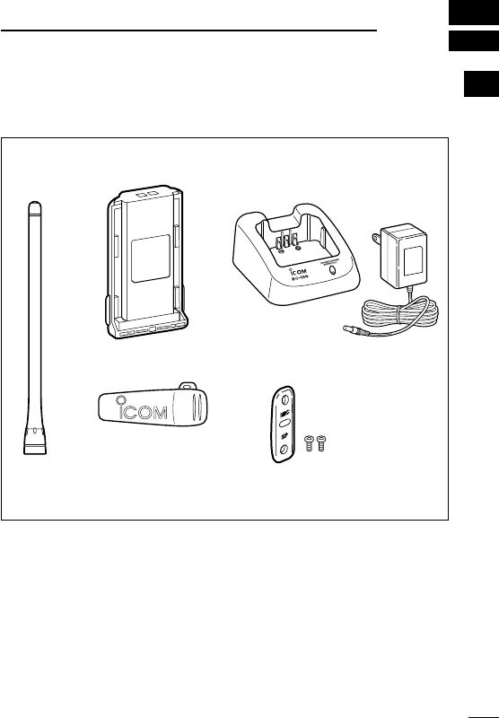
■ Supplied accessories
The following accessories are supplied.
Flexible
antenna*
Battery pack Battery carger
(with AC adapter)
Belt clip Jack cover (with screws)
*This illustration is described
with the VHF type.
1
2
3
4
5
6
7
8
9
10
11
12
13
14
15
16
17
18
19
20
2
1ACCESSORIES
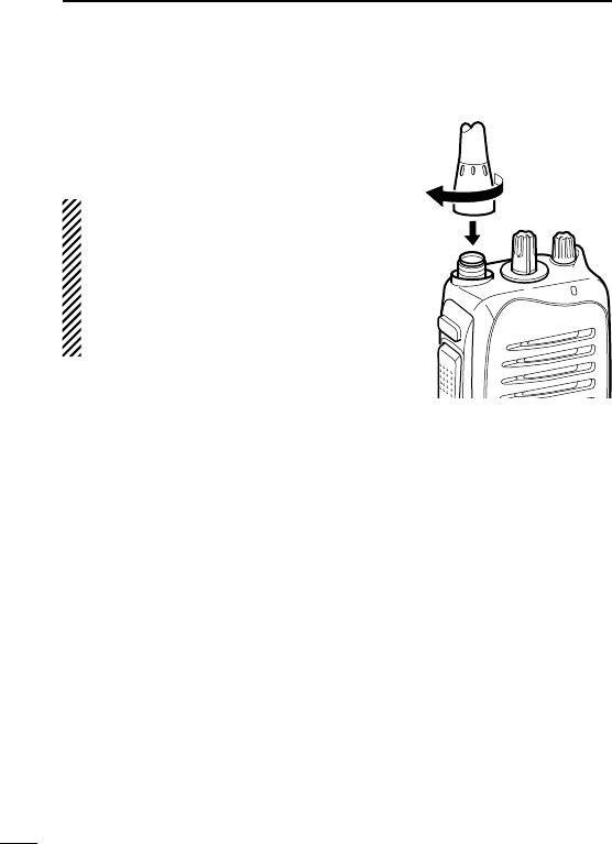
■ Accessory attachments
D Flexible antenna
Connect the supplied flexible antenna to
the antenna connector.
CAUTION:
•NEVER carry the transceiver by
holding only the antenna.
•DO NOT connect the antenna other
thanlistedonpage34.
•Transmitting without an antenna
may damage the transceiver.
3
1
ACCESSORIES
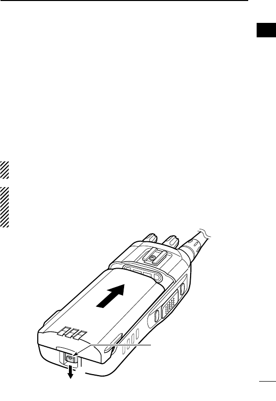
D Battery pack
To attach the battery pack:
Slide the battery pack on the back of the transceiver in the direction
ofthearrow(q),thenlockitwiththebatteryreleasebutton.
•Slidethebatterypackuntilthebatteryreleasebuttonmakesa‘click’
sound.
To remove the battery pack:
Pushthebatteryreleasebuttoninthedirectionofthearrow(w)as
shown below. The battery pack is then removed.
NOTE:Keepthebatteryterminalsclean.It’sagoodideatooc-
casionally clean them.
NEVER remove or attach the battery pack when the transceiver
is wet or soiled. This may result in water or dust getting into the
transceiver/batterypackandmayresultinthetransceiverbeing
damaged.
q
w
Battery release
button
1
2
3
4
5
6
7
8
9
10
11
12
13
14
15
16
17
18
19
20
4
1ACCESSORIES
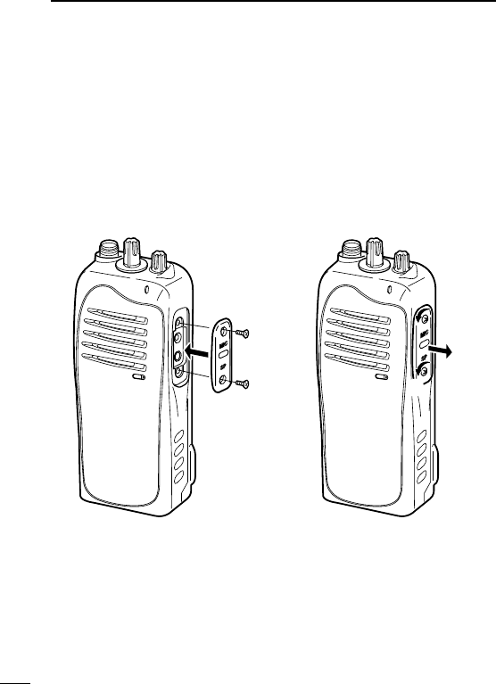
D Jack cover
Attach the jack cover when the optional speaker-microphone is not
used.
To attach the jack cover:
q Attach the jack cover to the
[SP MIC] connector.
w Tighten the screws.
To detach the jack cover:
e Remove the screws with a
phillips screwdriver.
r Detach the jack cover for the
optional equipment connec-
tion.
e
e
r
w
w
q
5
1
ACCESSORIES
D Belt clip
To attach the belt clip:
q Remove the battery pack if it is attached.
w Slide the belt clip in the direction of the arrow until the belt clip is
lockedandmakesa‘click’sound.
To detach the belt clip:
q Remove the battery pack if it is attached.
wPinchtheclip(q),andslidethebeltclipinthedirectionofthe
arrow(w).
q
w
1
2
3
4
5
6
7
8
9
10
11
12
13
14
15
16
17
18
19
20
6
2PANEL DESCRIPTION
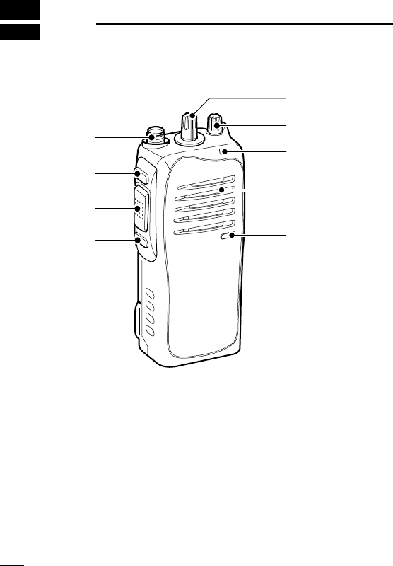
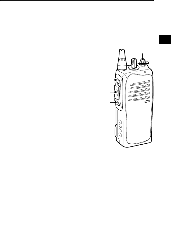
■ Front, top and side panels
Microphone
Speaker
r
w
e
y
u
i
t
q
q CHANNEL SELECTOR
Rotate the channel selector to select the pre-programmed mem-
ory channels.
w VOLUME CONTROL [VOL]
RotatetoturnthepowerON/OFFandadjusttheaudiolevel.
7
2
PANEL DESCRIPTION
e LED INDICATOR(p.8)
➥ Lights red while transmitting.
➥ Lights green while receiving a signal, or when the squelch is
open.
➥Lights/blinksorangewhenthematched2/5-tonecodeisre-
ceived,accordingtothepre-programming.(ForIC-F3013/
F4013only)
r SPEAKER-MICROPHONE CONNECTOR [SP MIC]
Connects the optional speaker-microphone, earphone, etc.
[SP MIC] jack cover
NOTE: Attach the [SP MIC] jack
cover when the optional equip-
ment is not used. (p. 4)
t DEALER-PROGRAMMABLE KEY [Lower]
Thedesiredfunctioncanbeassignedbyyourdealer.(p.9)
y PTT SWITCH [PTT]
Push and hold to transmit; release to receive.
u DEALER-PROGRAMMABLE KEY [Upper]
Thedesiredfunctioncanbeassignedbyyourdealer.(p.9)
i ANTENNA CONNECTOR
Connects the supplied antenna.
1
2
3
4
5
6
7
8
9
10
11
12
13
14
15
16
17
18
19
20
8
2PANEL DESCRIPTION
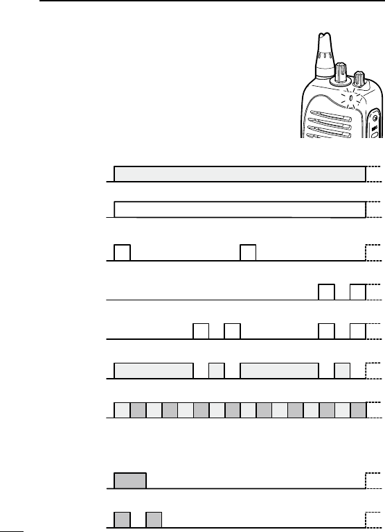
■ LED indicator
The LED indicator indicates several information
as follows;
(Ref.;R=Red,G=Green,O=Orange)
R R R R
G G G G
G G
G G G G G G G G
R G R G R G R G R G R G R G R G
R O R O R O R O R O R O R O R O
G
G G
Clone Err
Clone TX/RX
Low BATT1
Low BATT2
Busy
F/S Scan
O O
O O
Call LED Blink
Call LED ON
TX Low BATT2
R
TX
•TX:TurnsRedwhiletransmittingasignal.
•RX:TurnsGreenwhilereceivingasignal.
For IC-F3013/IC-F4013 only
•CallLED(ON):Whenreceivingamatched2/5-tone.
•CallLED(Blink):Whenreceivingamatched2/5-tone.
•Fast/Slowscan:BlinkswhileFast/Slowscanisactivated.
•LowBATT1:Youshouldchargethebattery.(blinksslowly)
•LowBATT2:Youmustchargethebattery.(blinksfast)
•TXlowBATT2:LowBATT2wasdetectedduringTXmode.
•CHerror:Non-programmedchannelisselected.

9
2
PANEL DESCRIPTION
■ Programmable function keys
The following functions can be assigned to [Upper] and [Lower]
programmable function keys.
Consult your Icom dealer or system operator for details concerning
your transceivers programming.
D For All models
SCAN A KEY
➥ Push to start and cancel scanning operation.
➥ When the Power ON scan function is turned ON, push to pause
the scanning operation. The paused scan restarts after the spec-
ified time period has passed.
SCAN B KEY
Push to start and cancel scanning operation. In case of transmis-
sion during scan, pauses scanning. The paused scan restarts after
the specified time period has passed.
PRIORITY CHANNEL KEYS
➥PushtoselectthePriorityAorPriorityBchannel.
➥ Push and hold [Prio A (Rewrite)] to rewrite the Prio A channel.
MR-CH 1/2/3/4 KEYS
Pushtoselectamemorychannels1to4directly.
1
2
3
4
5
6
7
8
9
10
11
12
13
14
15
16
17
18
19
20

10
2PANEL DESCRIPTION
OUTPUT POWER SELECTION KEY
Select the transmit output power temporarily or permanently, de-
pending on the pre-setting.
•Askyourdealerfortheoutputpowerlevelforeachselection.
TALK AROUND KEY
➥ Push to turn the talk around function OFF.
➥ Push and hold to turn the talk around function ON.
•Thetalkaroundfunctionequalizesthetransmitfrequencytothe
receive frequency for transceiver-to-transceiver communication.
WIDE/NARROW KEY
➥ Push to select the IF bandwidth to wide.
•Thewidepassbandwidthcanbeselectedfrom25or20kHzusing
theoptionalcloningsoftware(PMRoperationonly).Askyourdealer
for details.
➥ Push and hold to select the IF bandwidth to narrow.
SIREN KEY
Push to emit a siren. This function can be used for situations other
than an emergency alert such as a security alarm for example.
LOCK KEY
Push and hold to electronically lock all programmable keys except
the followings:
[Moni(Audi)], [Call](incl.CallAandCallB)*and
[Emergency Single]/[Emergency Repeat]
(incl.Silent)*.
*AvailableforIC-F3013/IC-F4013only.

11
2
PANEL DESCRIPTION
MONITOR KEY
➥PushtomuteandreleasetheCTCSS(DTCS)or2Tone*squelch
mute.Openanysquelches/deactivateanymuteswhilepushing
this key. (LMRoperationonly)
*AvailablefortheIC-F3013/F4013only.
➥Activatesoneof(ortwoof)thefollowingfunctionsoneachchan-
nel independently: (PMRoperationonly)
•Pushandholdtoun-mutethechannel(audioisemitted;‘Audible’).
•Pushtomutethechannel(audioisnotemitted;‘Inaudible’).
•Pushtosenda‘resetcode’afterthecommunicationisnished.
NOTE:Theun-mutecondition(‘Audible’condition)mayauto-
maticallyreturntothemutecondition(‘Inaudible’condition)
after a specified period.
D For IC-F3013/IC-F4013 only
DTMF AUTODIAL KEY
Push to transmit the programmed DTMF code.
CALL KEYS
Pushtotransmita2/5-tonecode.
•Calltransmissionisnecessarybeforeyoucallanotherstationdepend-
ing on your signalling system.
•[CallA]and/or[CallB]keysmaybeavailablewhenyoursystemem-
ploysselective‘Individual/Group’calls.Askyourdealerwhichcallis
assigned to each key.
EMERGENCY SINGLE/EMERGENCY REPEAT KEYS
➥ Push and hold for the specified time period to transmit an emer-
gency call once or repeatedly.
➥
When [Emergency Single (Silent)] or [Emergency Repeat (Silent)]
is pushed, an emergency call is transmitted with no beep emission.
•Ifyouwanttocanceltheemergencycall,push(orpushandhold)
the key again before transmitting the call.
•Theemergencycallistransmittedonetimeonlyorrepeatedlyuntil
receiving a control code depending on the pre-setting.
1
2
3
4
5
6
7
8
9
10
11
12
13
14
15
16
17
18
19
20
12
3
CONVENTIONAL OPERATION
■ Turning power ON
Rotate [VOL] to turn power ON.
■ Channel selection
Rotate [CHANNEL SELECTOR] to se-
lect the desired operating channel, in
sequence; or, push one of [MR-CH 1] to
[MR-CH 4] key to select a channel di-
rectly.
AUTOMATIC SCAN TYPE:
Channel setting is not necessary for this
type. When turning the power ON, the
transceiver automatically starts scanning.
Scanning stops when receiving a call.
[VOL]
[CHANNEL
SELECTOR]

13
3
CONVENTIONAL OPERATION
■ Receiving and transmitting
NOTE: Transmitting without an antenna may damage the trans-
ceiver.Seepage2forantennaattachment.
Receiving:
q Rotate [VOL] to turn power ON.
w Rotate [CHANNEL SELECTOR] or push one of [MR-CH 1] to
[MR-CH 4] key to select a channel.
e When receiving a call, adjust the audio output level to a comfort-
able listening level.
Transmitting:
Wait for the channel to become clear to avoid interference.
q While pushing and holding [PTT], speak into the microphone at
a normal voice level.
w Release [PTT] to return to receive.
IMPORTANT: To maximize the readability of your signal;
1. Pause briefly after pushing [PTT].
2.Holdthemicrophone5to10cm(2to4inches)fromyour
mouth, then speak into the microphone at a normal voice
level.
1
2
3
4
5
6
7
8
9
10
11
12
13
14
15
16
17
18
19
20

14
3CONVENTIONAL OPERATION
D Transmitting notes
• Transmit inhibit function
The transceiver has several inhibit functions which restrict trans-
mission under the following conditions:
- The channel is in mute condition.
- The channel is busy.
-Un-matched(ormatched)CTCSSisreceived.
-Theselectedchannelisa‘receiveonly’channel.
• Time-out timer
After continuous transmission for the pre-programmed time period, the
time-out timer activates, and causes the transceiver to stop transmit-
ting.
• Penalty timer
Once the time-out timer activates, transmission is further inhibited
for a period determined by the penalty timer.
15
3
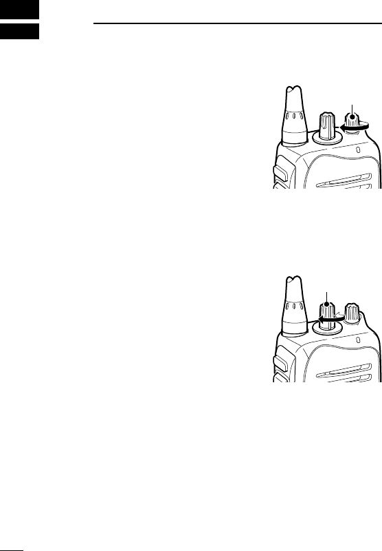
CONVENTIONAL OPERATION
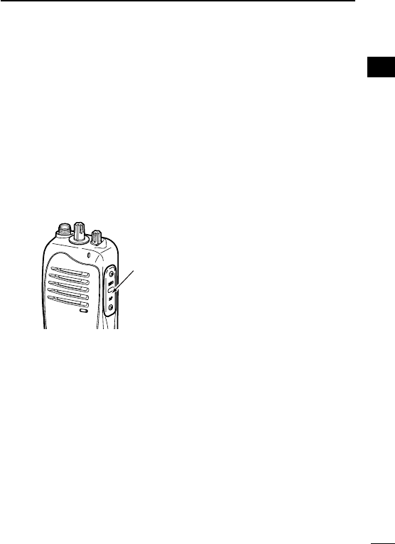
■ Setting the squelch level
The squelch circuit mutes the received audio signal depending on
the signal strength.
q While pushing [PTT] and [Lower],
rotate [VOL] to turn the power ON
to enter the squelch level adjust-
ment mode.
w Push [Upper] to increase the
squelch level (tight squelch) or
[Lower] to decrease the squelch
level(loosesquelch).
e Rotate [VOL] to turn the power
OFF to fix the squelch level.
1
2
3
4
5
6
7
8
9
10
11
12
13
14
15
16
17
18
19
20
[VOL]
[Upper]
[Lower]
[PTT]
16
4SIGNALING OPERATIONS
NOTE: The tone signalling operations are available for the
IC-F3013/F4013only.
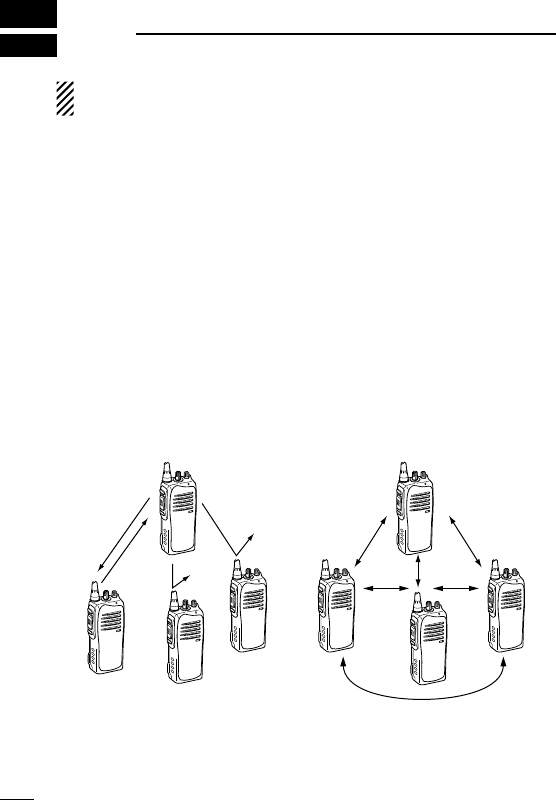
■ Call procedure
Whenyoursystememploystonesignalling(excludingCTCSSand
DTCS),thecallproceduremaybenecessarypriortovoicetrans-
mission. The tone signalling employed may be a selective calling
systemwhichallowsyoutocallspecicstation(s)onlyandprevent
unwanted stations from contacting you.
qSelectthedesiredTXcodechannelor2/5-tonecodeaccording
toyourSystemOperator’sinstructions.
•Thismaynotbenecessarydependingonprogramming.
w Push [Call].(p.11)
eAftertransmittinga2/5-tonecode,theremainderofyourcom-
munication can be carried out in the normal fashion.
Selective calling Non-selective calling
D Transmitting notes— PTTID call
ThetransceiversendstheIDcode(5-tone,DTMFordigitalANI)
automatically when [PTT]ispushed(beginningoftransmission)
andreleased(endoftransmission)dependsonthesetting.

17
4
SIGNALING OPERATIONS
1
2
3
4
5
6
7
8
9
10
11
12
13
14
15
16
17
18
19
20
■ Emergency Call
When [Emergency Single] or [Emergency Repeat] (p. 11) is
pushed and held for the specified time period, the emergency sig-
nal(5-tone,DTMForMDC1200)istransmittedonceorrepeatedly
on the emergency channel. A repeat emergency signal is auto-
matically transmitted until it receives the acknowledgement signal.
When no emergency channel is specified, the signal is transmitted
on the previously selected channel.
If you want to cancel the emergency call, push and hold the key
again before transmitting the call.
The emergency call can be transmitted without a beep emission,
and the LCD indication if [Emergency Single (Silent)] or [Emer-
gency Repeat (Silent)](p.11)ispushed.
The transceiver can also be programmed to keep the microphone
open during an emergency call, allowing monitoring of the situa-
tion.
IMPORTANT: It is recommended to set an emergency channel
individually to provide the certain emergency call operation.
■ DTMF transmission
If the transceiver has [DTMF Autodial] assigned to it, the auto-
matic DTMF transmission function is available.
➥ Push [DTMF Autodial] to transmit the DTMF code.

18
5BATTERY CHARGING
■ Caution
Misuse of Lithium-ion batteries may result in the following
hazards: smoke, fire, or the battery may rupture. Misuse can
also cause damage to the battery or degradation of battery
performance.
R DANGER! Use and charge only specified Icom battery packs
with Icom radios or Icom charger. Only Icom battery packs are
tested and approved for use and charge with Icom radios or Icom
charger. Using third-party or counterfeit battery packs or charger
may cause smoke, fire, or cause the battery to burst.
D Battery caution
R DANGER! DO NOT hammer or otherwise impact the battery. Do
not use the battery if it has been severely impacted or dropped, or if
thebatteryhasbeensubjectedtoheavypressure.Batterydamage
may not be visible on the outside of the case. Even if the surface
of the battery does not show cracks or any other damage, the cells
inside the battery may rupture or catch fire.
R DANGER! NEVER use or leave battery packs in areas with
temperaturesabove+60˚C(+140˚F).Hightemperaturebuildupin
the battery, such as could occur near fires or stoves, inside a sun
heated car, or in direct sunlight may cause the battery to rupture or
catch fire. Excessive temperatures may also degrade battery per-
formance or shorten battery life.
R DANGER! DO NOT expose the battery to rain, snow, seawater,
or any other liquids. Do not charge or use a wet battery. If the bat-
tery gets wet, be sure to wipe it dry before using. The battery is not
waterproof.

19
5
BATTERYCHARGING
R DANGER! NEVER incinerate used battery packs since internal
battery gas may cause them to rupture, or may cause an explosion.
R DANGER! NEVER solder the battery terminals or NEVER mod-
ify the battery pack. This may cause heat generation, and the bat-
tery may rupture, emit smoke or catch fire.
R DANGER! Use the battery only with the transceiver for which it
is specified. Never use a battery with any other equipment, or for
any purpose that is not specified in this instruction manual.
R DANGER! If fluid from inside the battery gets in your eyes, blind-
ness can result. Rinse your eyes with clean water, without rubbing
them, and see a doctor immediately.
WARNING! Immediately stop using the battery if it emits an ab-
normal odor, heats up, or is discolored or deformed. If any of these
conditions occur, contact your Icom dealer or distributor.
WARNING! Immediately wash, using clean water, any part of the
body that comes into contact with fluid from inside the battery.
WARNING! NEVER put the battery in a microwave oven, high-
pressure container, or in an induction heating cooker. This could
cause a fire, overheating, or cause the battery to rupture.
CAUTION! Always use the battery within the specified temperature
rangeforthetransceiver(–30˚Cto+60˚C;–22˚Fto+140˚F)and
thebatteryitself(–20˚Cto+60˚C;–4˚Fto+140˚F).Usingthebat-
teryoutofitsspeciedtemperaturerangewillreducethebattery’s
performance and battery life.
1
2
3
4
5
6
7
8
9
10
11
12
13
14
15
16
17
18
19
20

20
5BATTERYCHARGING
CAUTION! Shorter battery life could occur if the battery is left fully
charged, completely discharged, or in an excessive temperature
environment(above+50˚C;+122˚F)foranextendedperiodoftime.
If the battery must be left unused for a long time, it must be de-
tached from the radio after discharging.
You may use the battery until the remaining capacity is about half, then
keep it safely in a cool dry place with the temperature range as below:
–20˚Cto+50˚C(–4˚Fto+122˚F) (withinamonth)
–20˚Cto+40˚C(–4˚Fto+95˚F) (withinthreemonths)
–20˚Cto+20˚C(–4˚Fto+68˚F) (withinayear)
D Charging caution
R DANGER! NEVER charge the battery pack in areas with ex-
tremely high temperatures, such as near fires or stoves, inside
a sun heated car, or in direct sunlight. In such environments, the
safety/protectioncircuitinthebatterywillactivate,causingthebat-
tery to stop charging.
WARNING! DO NOT charge or leave the battery in the battery
charger beyond the specified time for charging. If the battery is not
completely charged by the specified time, stop charging and re-
move the battery from the battery charger. Continuing to charge the
battery beyond the specified time limit may cause a fire, overheat-
ing, or the battery may rupture.
WARNING! NEVERinsertthetransceiver(batteryattachedtothe
transceiver)intothechargerifitiswetorsoiled.Thiscouldcorrode
the battery charger terminals or damage the charger. The charger
is not waterproof.
CAUTION! DO NOT charge the battery outside of the specified
temperaturerange:BC-160(0˚Cto+40˚C;+32˚Fto+104˚F).Icom
recommendschargingthebatteryat+20˚C(+68˚F).Thebattery
may heat up or rupture if charged out of the specified temperature
range. Additionally, battery performance or battery life may be re-
duced.
21
5
BATTERYCHARGING
■ Battery chargers
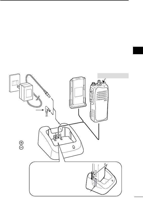
D Rapid charging with the BC-160
TheoptionalBC-160providesrapidchargingoftheLi-ionbattery
pack.Chargingperiod:Approximately3hours(withBP-232H)
The following items are additionally required:
•AnACadapter(notsuppliedwithsomeversions)ortheDCpower
cable(OPC-515L/CP-23L)isadditionallyrequired.
AC adapter
(A different type, or no AC adapter is
supplied, depending on the version.)
About OPC-515L
White line:
Black line :
*
Optional OPC-515L*
(for power source) or
CP-23L (for 12 V ciga-
rette lighter socket)
can be used instead
of the AC adapter.
Battery pack Transceiver
Tu rn power OFF
IMPORTANT!
Ensure the guide tabs on the
battery pack are correctly
aligned with the guide rails
inside the charger adapter.
Guide rail
Tabs
1
2
3
4
5
6
7
8
9
10
11
12
13
14
15
16
17
18
19
20
22
5BATTERYCHARGING
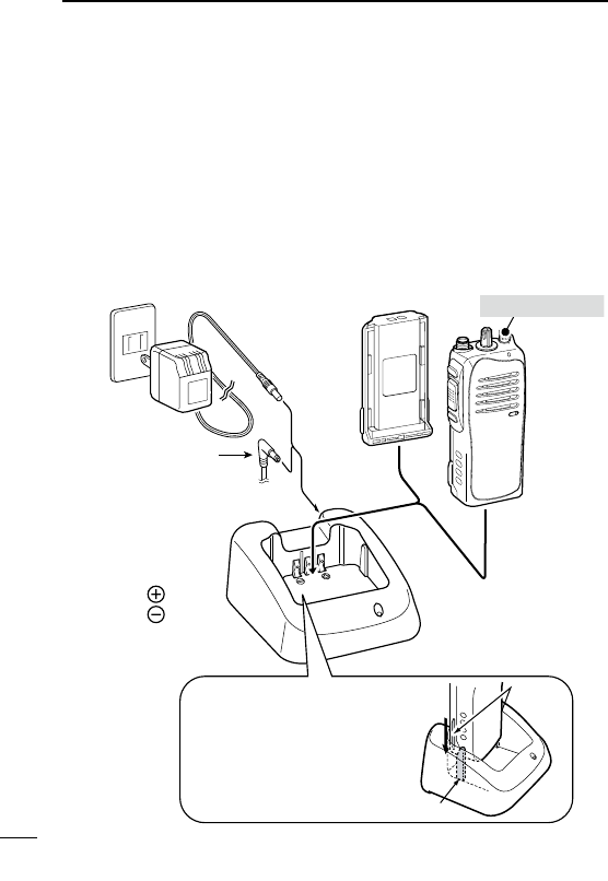
D Regular charging with the BC-171
TheoptionalBC-171providesregularchargingoftheLi-ionbattery
pack.
Chargingperiod:Approximately10hours(withBP-232H)
The following items are additionally required:
•AnACadapter(notsuppliedwithsomeversions)ortheDCpower
cable(OPC-515L/CP-23L)isadditionallyrequired.
AC adapter
(A different type, or no AC adapter is
supplied, depending on the version.)
About OPC-515L
White line:
Black line :
*
Optional OPC-515L*
(for power source) or
CP-23L (for 12 V ciga-
rette lighter socket)
can be used instead
of the AC adapter.
Battery pack Transceiver
Tu rn power OFF
IMPORTANT!
Ensure the guide tabs on the
battery pack are correctly
aligned with the guide rails
inside the charger adapter.
Guide rail
Tabs
23
5
BATTERYCHARGING
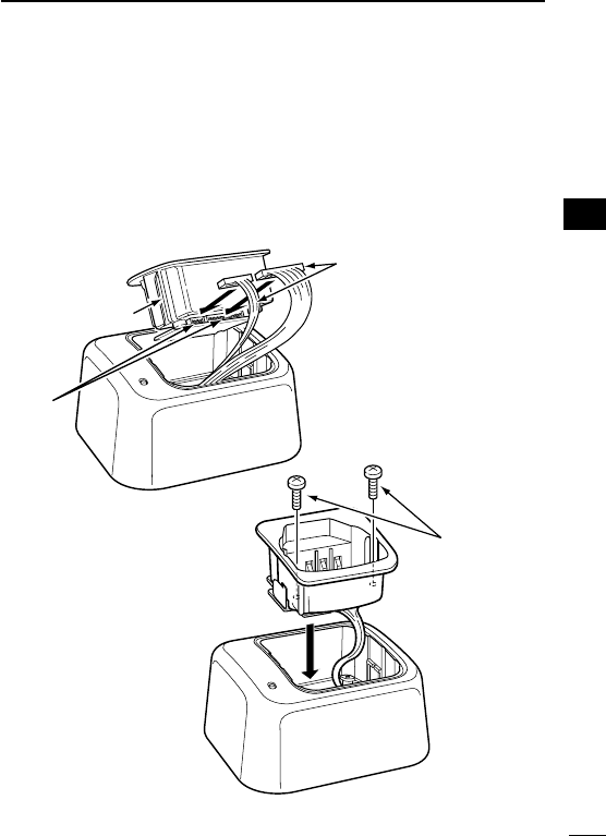
D AD-106 installation
TheAD-106c h a r g e r a d a p t e r mustbeinstalledintotheBC-119N
orBC-121Nbeforebatterycharging.
qAttachtheplugsfrom theBC-119N/BC-121Ntothe AD-106
c h a r g e r a d a p t e r .
wSecuretheAD-106intotheholderspaceoftheBC-119N/BC-
121Nwiththesuppliedscrews.
Desktop charger
adapter
Plugs
Sockets
Screws supplied
with the charger
adapter
ThisillustrationisdescribedwiththeBC-119N.
1
2
3
4
5
6
7
8
9
10
11
12
13
14
15
16
17
18
19
20
24
5BATTERYCHARGING
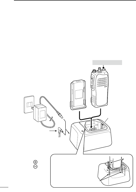
D Rapid charging with the BC-119N+AD-106
TheoptionalBC-119NprovidesrapidchargingoftheLi-ionbattery
pack.
Chargingperiod:Approximately3hours(withBP-232H)
The following items are additionally required:
•AnAD-106c h a r g e r a d a p t e r (purchaseseparately)
•AnACadapter(notsuppliedwithsomeversions)ortheDCpower
cable(OPC-515L/CP-23L).
AD-106 charger
adapter is installed
in BC-119N.
AC adapter
(A different type, or no AC
adapter is supplied, de-
pending on the version.)
About OPC-515L
White line:
Black line :
*
Optional OPC-515L*
(for power source) or
CP-23L (for 12 V ciga-
rette lighter socket)
can be used instead
of the AC adapter.
Battery pack
Transceiver
Tu rn power OFF
IMPORTANT!
Ensure the guide tabs on the
battery pack are correctly
aligned with the guide rails
inside the charger adapter.
Guide rails
Tabs
25
5
BATTERYCHARGING
1
2
3
4
5
6
7
8
9
10
11
12
13
14
15
16
17
18
19
20
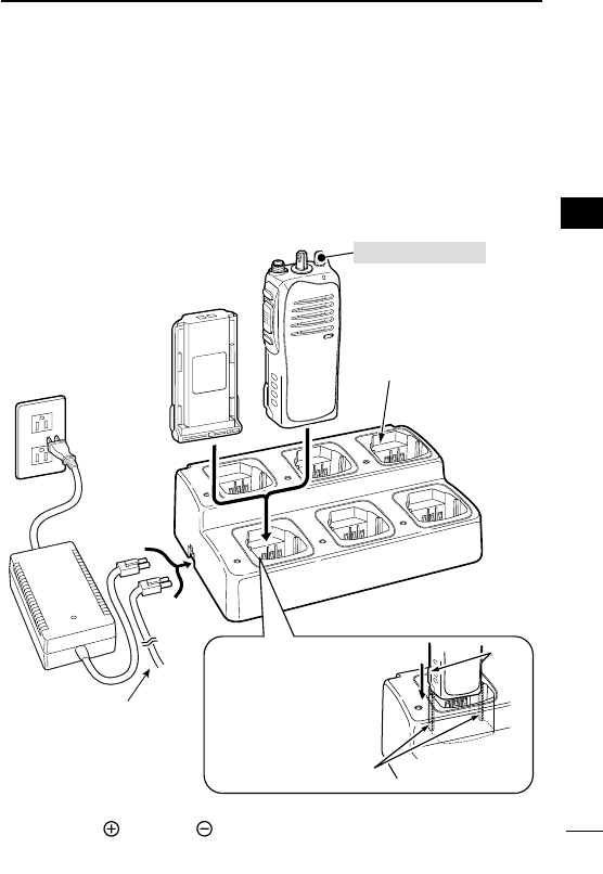
D Rapid charging with the BC-121N+AD-106
TheoptionalBC-121Nallowsupto6batterypackstobecharged
simultaneously.
Chargingperiod:Approximately3hours(withBP-232H)
The following items are additionally required.
•SixAD-106c h a r g e r a d a p t e r (purchaseseparately)
•AnACadapter(BC-157)ortheDCpowercable(OPC-656)
AC adapter
(Purchase
separately)
AD-106 charger
adapters are installed
in each slot.
DC power cable
(OPC-656*)
(Connect with a DC
power supply; 13.8 V/at
least 7 A)
*About the OPC-656
Red line: Black line:
Battery pack Transceiver
Tu rn power OFF
IMPORTANT!
Ensure the guide tabs
on the battery pack are
correctly aligned with
the guide rails inside
the charger adapter.
Guide rails
Tabs

26
6BATTERY CASE
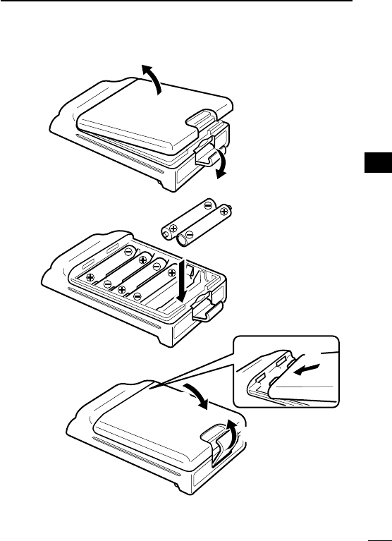
■ Optional battery case (BP-240)
Whenusingtheoptionalbatterycase,install6×AAA(LR03)size
alkaline batteries as illustrated at right.
qUnhookthebatterycoverreleasehook(q),andopenthecover
inthedirectionofthearrow(w).(Fig.1)
wThen,install6×AAA(LR03)sizealkalinebatteries.(Fig.2)
•Installthealkalinebatteriesonly.
•Besuretoobservethecorrectpolarity.
eFitthecoverinthedirectionofthearrow(e),thenclose(r).
Hookthebatterycoverreleasehookuntilitmakesa‘click’sound
(t). (Fig.3)
CAUTION:
•When installing batteries, makesuretheyare allthesame
brand, type and capacity. Also, do not mix new and old batter-
ies together.
•Keepbatterycontactsclean.It’sagoodideatooccasionally
clean them.
•Neverincinerateusedbatterycellssinceinternalbatterygas
may cause them to rupture.
•Neverexposeadetachedbatterycasetowater.Ifthebattery
case gets wet, be sure to wipe it dry before using it.
NOTE: When the optional battery case is attached, the battery
type must be selected to “Alkaline battery operation” when turn-
ing the transceiver ON. Ask your dealer for details.
27
6
BATTERYCASE
1
2
3
4
5
6
7
8
9
10
11
12
13
14
15
16
17
18
19
20
q
BP-240
w
Fig.1
Fig.2
Fig.3
e
r
t
28
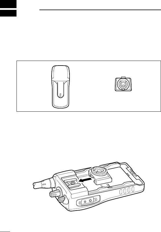
7SWIVEL BELT CLIP
■ MB-93 contents
Qty.
qBeltclip .................................................................................... 1
wBaseclip .................................................................................. 1
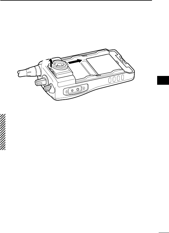
■ To attach
qRemovethebatterypackifitisattached.(p.3)
w Slide the base clip in the direction of the arrow until the base clip
islockedandmakesa‘click’sound.
q w
29
7
SWIVELBELTCLIP
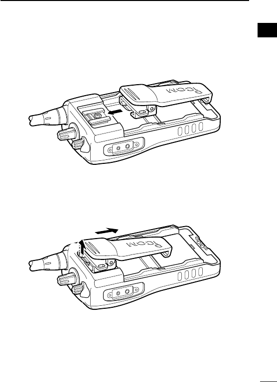
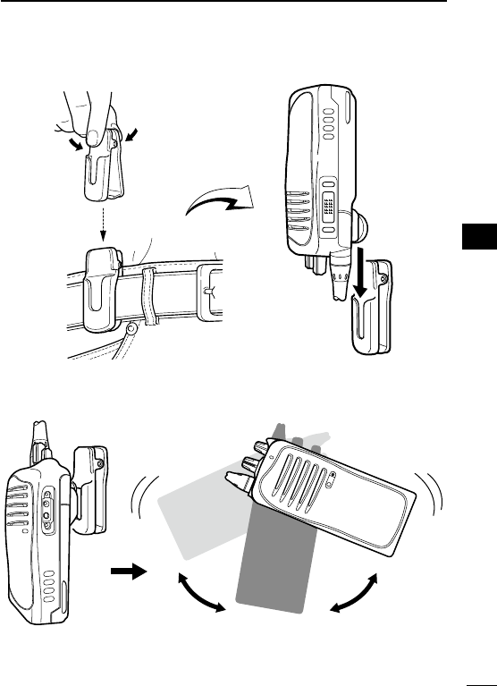
e Clip the belt clip to a part of your belt. And insert the transceiver
into the belt clip until the base clip inserted fully into the groove.
r Once the transceiver is locked in place, it swivels as illustrated
below.
Once the transceiver is locked in place,
it will swivel 360 degrees.
1
2
3
4
5
6
7
8
9
10
11
12
13
14
15
16
17
18
19
20
30
7SWIVELBELTCLIP
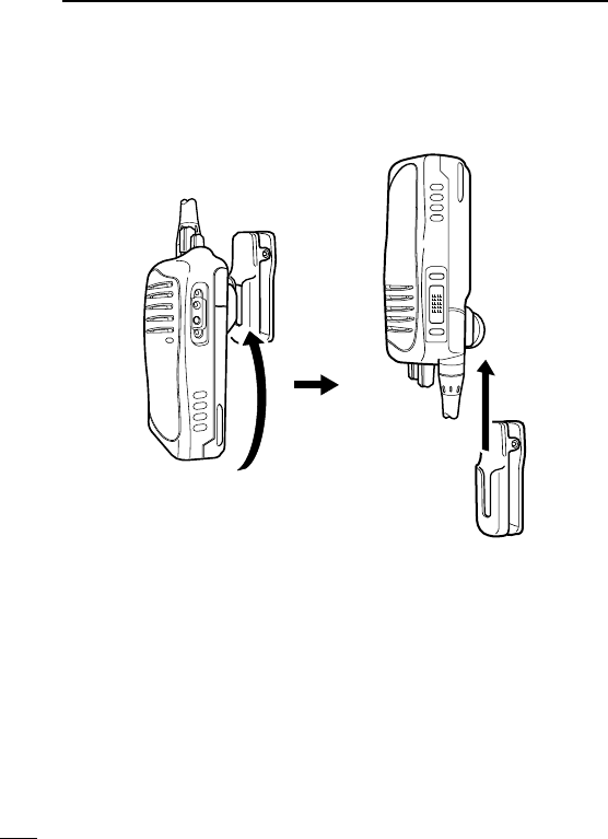
■ To detach
q Turn the transceiver upside down in the direction of the arrow
and pull out from the belt clip.
31
7
SWIVELBELTCLIP
6
wRemovethebatterypackifitisattached.(p.3)
ePinchtheclip(q),andslidethebaseclipinthedirectionofthe
arrow(w).
qw
CAUTION:
HOLD THE TRANSCEIVER TIGHTLY, WHEN HANGING OR
DETACHING THE TRANSCEIVER FROM THE BELT CLIP.
Otherwise the transceiver may not be attached to the holder or
swivel properly if the transceiver is accidentally dropped and the
base clip is scratched or damaged.
1
2
3
4
5
7
8
9
10
11
12
13
14
15
16
17
18
19
20

32
8OPTIONS
D BATTERY PACK
Battery pack Voltage Capacity Battery life*1
BP-230N 7.4V 950mAh(min.)
980mAh(typ.) 9hrs.
BP-232N 7.4V 1900mAh(min.)
2000mAh(typ.) 18 hrs.
BP-232H 7.4V 2250mAh(min.)
2300mAh(typ.) 21hrs.
BP-240 BatterycaseforAAA
(LR03)×6alkaline —*2
*1
When the power save function is turned ON, and the operating pe-
riods are calculated under the following conditions;
TX:RX:standby=5:5:90
*2 Operating period depends on the alkaline cells used.
D CHARGERS
• BC-119N d e s k t o p c h a r g e r + AD-106 c h a r g e r a d a p t e r
+ BC-145S a c a d a p t e r
For rapid charging of battery packs. An AC adapter is supplied
with the charger depending on versions.
Charging time:
Approximately3hourswhenBP-232Hisattached.
• BC-121N m u l t i -c h a r g e r + AD-106 c h a r g e r a d a p t e r (6pcs.)
+ BC-157 a c a d a p t e r
Forrapidchargingofupto6batterypacks(sixAD-106’sarerequired)
simultaneously. An AC adapter should be purchased separately.
Charging time:
Approximately3hourswhenBP-232Hisattached.

33
8
OPTIONS
• BC-160 d e s k t o p c h a r g e r + BC-145S a c a d a p t e r
For rapid charging of battery packs. An AC adapter is supplied
with the charger depending on versions.
Charging time:
Approximately3hourswhenBP-232Hisattached.
• BC-171 d e s k t o p c h a r g e r + BC-147S a c a d a p t e r
For regular charging of battery packs. We recommend that the
BP-230Ncharging. An AC adapter is suppliedwith the charger
depending on versions.
Chargingtime:Approximately11hourswhenBP-232Hisattached.
Approximately4hourswhenBP-230Nisattached.
D BELT CLIPS
• MB-93 s w i v e l b e lt c l i p
• MB-94 b e lt c l i p
Exclusive alligator-type belt clip.
• MB-96N/96F l e at h e r b e lt h a n g e r
D DC CABLES
• CP-23L c i g a r e t t e l i g h t e r c a b l e
Allowschargingofthebatterypackthrougha12Vcigarettelighter
socket.(ForBC-119N/BC-160/BC-171)
• OPC-515L/OPC-656 d c p o w e r c a b l e s
Allows charging of the battery pack using a 13.8 V power source
instead of the AC adapter.
OPC-515L:ForBC-119N/BC-160/BC-171
OPC-656 :ForBC-121N
1
2
3
4
5
6
7
8
9
10
11
12
13
14
15
16
17
18
19
20

34
8OPTIONS
D ANTENNAS
• FA-SC73US/FA-SC56VS/FA-SC57VS s t u b b y a n t e n n a s
FA-SC73US:450–490MHz FA-SC56VS:150–162MHz
FA-SC57VS:160–174MHz
• FA-SC01U/FA-SC25U/FA-SC57U/FA-SC72U/FA-SC25V/
FA-SC55V a n t e n n a s
FA-SC01U:350–400MHz FA-SC25U:400–430MHz
FA-SC57U:430–470MHz FA-SC72U:470–520MHz
FA-SC25V:136–155MHz FA-SC55V:146–174MHz
• FA-SC61VC/FA-SC61UC c u t a n t e n n a s
FA-SC61VC:136–174MHz FA-SC61UC:380–520MHz
D OTHER OPTIONS
• SP-13 e a r p h o n e
Provides clear receive audio in noisy environment.
• HM-153L e a r p h o n e -m i c r o p h o n e
• HM-131L/158L/159L s p e a k e r -m i c r o p h o n e
Combination speaker-microphone that provides convenient op-
eration while hanging the transceiver from your belt.
• VS-1L v o x /p t t c a s e +HS-94/HS-95/HS-97 h e a d s e t
VS-1L:VOX/PTTswitchboxforhands-freeoperation,etc.
HS-94:Earhooktype HS-95:Neck-armtype
HS-97:Throatmicrophone
• MB-130 v e h i c l e c h a r g e r b r a c k e t
VehiclemountingbracketfortheBC-160batterycharger.
Approved Icom optional equipment is designed for optimal performance
when used with an Icom transceiver.
Icom is not responsible for the destruction or damage to an Icom trans-
ceiver in the event the Icom transceiver is used with equipment that is
not manufactured or approved by Icom.
Some options may not be available in some countries. Please ask your
dealer for details.
35
8
OPTIONS
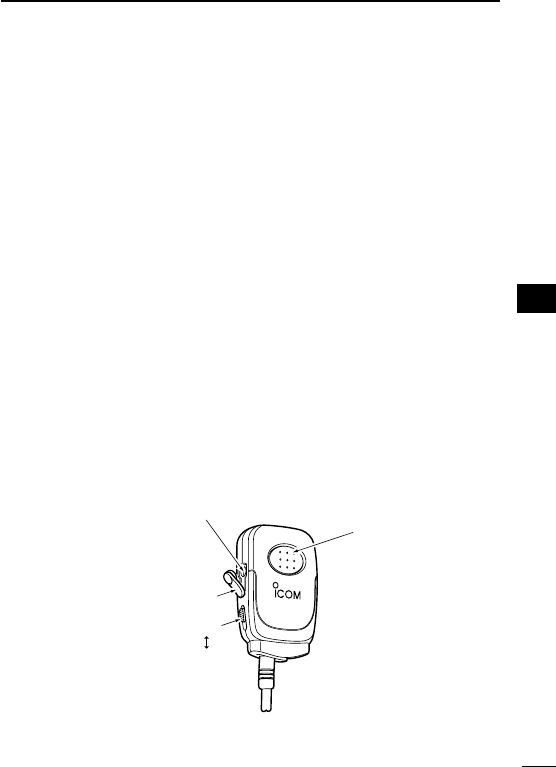
D About VS-1L v o x /p t t c a s e
TheVS-1LisaVOX/PTTunitforIcomhandheldtransceivers,and
allows you hands-free operation.
Anoptionalheadset(HS-94,etc.)isadditionallyrequiredforopera-
tion.
•TheVOX(voiceoperatedtransmission)functionstartstransmission
without pushing PTT switch when you speak into the microphone;
then, automatically returns to receive when you stop speaking.
Features
➥StraighttypeheadSP/MICplugequipped
➥ Water resistant construction
➥ Durable construction
➥ Equipped with a PTT switch and revolving clip.
MIC/VOX gain adjustment
1 Remove the water protection cover on the right side of the VS-1L.
2AdjusttheMIC/VOXgainwithathinscrewdriver.Clockwiserota-
tionincreasestheMIC/VOXgain.
3ReturntheprotectivecoverbacktotheMIC/VOXgainadjustment
hole.
VS-1L
VOX
PTT
Adjusting pot
Water protection cover
PTT switch
1
2
3
4
5
6
7
8
9
10
11
12
13
14
15
16
17
18
19
20

36
9FCC INFORMATION
• FOR CLASS B UNINTENTIONAL RADIATORS:
This equipment has been tested and found to comply with the limits
foraClassBdigitaldevice,pursuanttopart15oftheFCCRules.
These limits are designed to provide reasonable protection against
harmful interference in a residential installation. This equipment
generates, uses and can radiate radio frequency energy and, if not
installed and used in accordance with the instructions, may cause
harmful interference to radio communications. However, there is no
guarantee that interference will not occur in a particular installation.
If this equipment does cause harmful interference to radio or televi-
sion reception, which can be determined by turning the equipment
off and on, the user is encouraged to try to correct the interference
by one or more of the following measures:
•Reorientorrelocatethereceivingantenna.
•Increasetheseparationbetweentheequipmentandreceiver.
•Connecttheequipmentintoanoutletonacircuitdifferentfrom
that to which the receiver is connected.
•Consultthedealeroranexperiencedradio/TVtechnicianfor
help.

MEMO
1
2
3
4
5
6
7
8
9
10
11
12
13
14
15
16
17
18
19
20

MEMO

MEMO
1
2
3
4
5
6
7
8
9
10
11
12
13
14
15
16
17
18
19
20

MEMO

MEMO
1
2
3
4
5
6
7
8
9
10
11
12
13
14
15
16
17
18
19
20

1-1-32Kamiminami,Hirano-ku,Osaka547-0003,Japan
A-6768H-1EX-w
PrintedinJapan
©2009–2012IcomInc.
Printed on recycled paper with soy ink.