ICOM orporated 278800 VHF/UHF Digital Transceiver User Manual ID 800H FCC
ICOM Incorporated VHF/UHF Digital Transceiver ID 800H FCC
UserManual.wiki
>
ICOM orporated
>
278800 User Manual
>
Users Manual Part 1
Contents
1.
Users Manual Part 1
2.
Users Manual Part 2
Users Manual Part 1
Navigation menu
Upload a User Manual
Namespaces
Wiki Guide
HTML
PDF
Info
Views
User Manual
Discussion / Help
Navigation
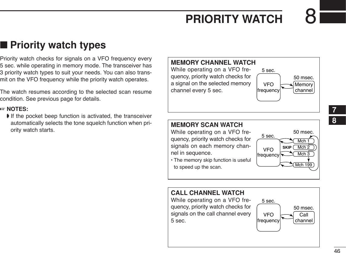
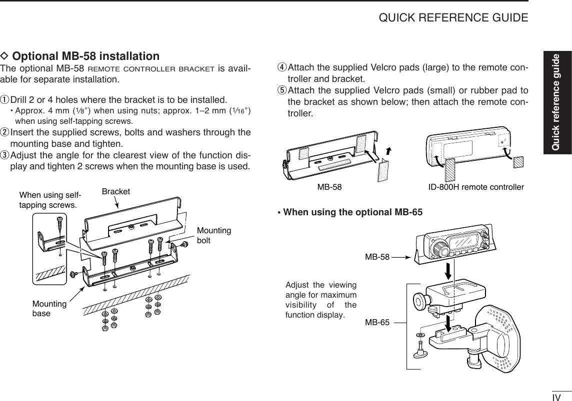
![iiiTABLE OF CONTENTSSUPPLIED ACCESSORIESqDC power cable (3 m) ………………………………………1wMobile mounting bracket …………………………………1eMicrophone (HM-133)* ……………………………………1rFuse (20 A) …………………………………………………1tMounting screws, nuts and washers …………………1 setyMicrophone hanger …………………………………………1uSeparation cable†(3.5 m; 11.5 ft) …………………………1*HM-118N HAND MICROPHONEor HM-118TN/TAN DTMF MICROPHONEsupplied versions are also available.†Aferrite core is adapted for the USA version.qwertyuFOREWORD ........................................................................................... iIMPORTANT ............................................................................................ iEXPLICIT DEFINITIONS ......................................................................... iPRECAUTION ........................................................................................ iiSUPPLIED ACCESSORIES .................................................................. iiiTABLE OF CONTENTS ......................................................................... iiiQUICK REFERENCE GUIDE ............................................................. I–X■Installation ....................................................................................... I■Your first contact .......................................................................... VII■Repeater operation ....................................................................... IX■Programming memory channels..................................................... X1PANEL DESCRIPTION ............................................................... 1–10■Front panel— controller ................................................................. 1■Function display ............................................................................. 3■Rear panel ..................................................................................... 5■Microphone (HM-133) .................................................................... 7■Microphone keypad ........................................................................ 8■Optional microphones (HM-118N/TN/TAN)................................... 102SETTING A FREQUENCY ........................................................ 11–14■Preparation ................................................................................... 11■Using the tuning dial .................................................................... 12■Using the [Y]/[Z] keys ................................................................. 12■Using the keypad ......................................................................... 12■Tuning step selection ................................................................... 13■Lock functions .............................................................................. 143BASIC OPERATION ................................................................. 15–18■Receiving ..................................................................................... 15■Monitor function ........................................................................... 15■Squelch attenuator ....................................................................... 16■Transmitting ................................................................................. 17■Selecting output power ................................................................ 17](https://usermanual.wiki/ICOM-orporated/278800.Users-Manual-Part-1/User-Guide-473908-Page-4.png)
![VIIQUICK REFERENCE GUIDE■Your first contactNow that you have your ID-800H installed in your car orshack, you are probably excited to get on the air. We wouldlike to take you through a few basic operation steps to makeyour first “On The Air” an enjoyable experience. 1. Turning ON the transceiverBefore powering up your ID-800H, you may want to makesure the audio volume and squelch level controls are set in9–10 o’clock positions.Although you have purchased a brand new transceiver, somesettings may be changed from the factory defaults becauseof the QC process. Resetting the CPU is necessary to startfrom factory default.➥While pushing both [SET•LOCK] and [S.MW•MW], push[PWR] for 1 sec. to reset the CPU.2. Selecting the operating frequency bandThe ID-800H has 2 m and 70 cm transmittable bands. ➥Push [BAND] to select the desired frequency band.Using the HM-133You can select the desired frequency band from the HM-133.PushPushPush [BAND] to select the desired frequency band.[BAND][PWR]While pushing [SET•LOCK] and [S.MW•MW], turn power ON.[SET•LOCK][S.MW•MW][VOL]Set [VOL] and [SQL] controls to 9–10 o’clock positions.[SQL]](https://usermanual.wiki/ICOM-orporated/278800.Users-Manual-Part-1/User-Guide-473908-Page-12.png)
![VIIIQUICK REFERENCE GUIDE3. Tune the frequencyThe tuning dial will allow you to dial in the frequency you wantto operate. Pages 12 and 13 will instruct you on how to setthe tuning speed.Using the HM-133You can directly enter the frequency with the HM-133 keypadfor the main band. [EXAMPLE]: Setting frequency to 145.3625 MHz.PushPushPushPushRotate [DIAL] to tune the frequency.[DIAL]Quick reference guide](https://usermanual.wiki/ICOM-orporated/278800.Users-Manual-Part-1/User-Guide-473908-Page-13.png)
![IXQUICK REFERENCE GUIDE■Repeater operation1. Setting duplex Push [BAND] to select the frequency band.Push [LOW•DUP] for 1 sec. once or twice to select minus du-plex or plus duplex.•The USA version has an auto repeater function, therefore, settingduplex is not required.2. Repeater tone Push [TONE•T-SCAN] several times until “T” appears, if therepeater requires a subaudible tone to be accessed.Using the HM-133Plus or minus duplex selection and the repeater tone settingcan be made easily via HM-133.Push [DUP–7(TONE)] for minus duplex; [DUP+8(TSQLS)]for plus duplex selection, push [FUNC] then [DUP–7(TONE)]to turn the repeater tone ON.PushPush , then Push[TONE•T-SCAN][LOW•DUP]](https://usermanual.wiki/ICOM-orporated/278800.Users-Manual-Part-1/User-Guide-473908-Page-14.png)
![XQUICK REFERENCE GUIDEQuick reference guide■Programming memory channelsThe ID-800H has a total of 512 memory channels (including10 scan edges and 2 call channels) for storing often used op-erating frequency, repeater settings, etc. 1. Setting a frequencyIn VFO mode, set the desired operating frequency with re-peater, tone and tuning steps, etc. ➥Push [V/MHz•SCAN] to select VFO.➥Rotate [DIAL] to set the desired frequency.•Set other data, such as repeater tone, duplex information, tuningstep), if desired.2. Selecting a memory channel Push [S.MW•MW], then rotate [DIAL] to select the desiredmemory channel.•“!” indicator and memory channel number blink.3. Writing a memory channelPush and hold [S.MW•MW] for 1 sec. to program.•3 beeps sound•Return to VFO mode automatically after the program.•Memory channel number automatically increases when continuingto push [S.MW•MW] after programming.Using the HM-133qIn VFO mode, set the desired operating frequency, includ-ing offset direction, tone settings, etc.➥Push [VFO/LOCK] to select VFO.➥Push [ENTC(T-OFF)] first, then enter the desired oper-ating frequency via the keypad.•Set other data, such as repeater tone, duplex information,tuning step, if necessary.wPush [FUNC] then [CLRA(MW)].•“!” indicator and memory channel number blink.ePush [Y]/[Z] to select the desired memory channel.rPush [FUNC] then push [CLRA(MW)] for 1 sec. to pro-gram.•3 beeps sound•Memory channel number automatically increases when continu-ing to push [CLRA(MW)] after programming.Push , then [S.MW•MW]](https://usermanual.wiki/ICOM-orporated/278800.Users-Manual-Part-1/User-Guide-473908-Page-15.png)
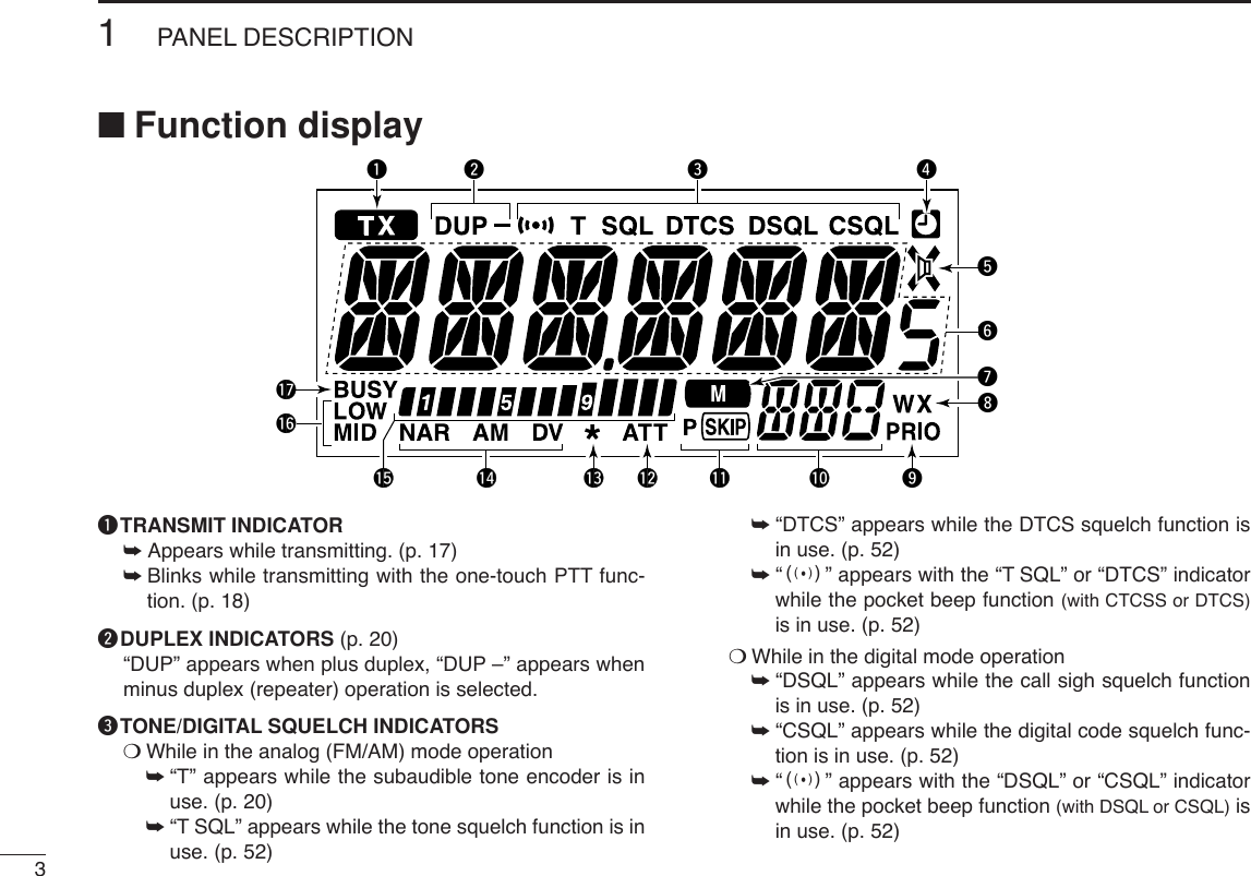
![■Front panel— controllerqSET•LOCK SWITCH [SET•LOCK]➥Enters set mode when pushed. (p. 56)➥Switches the lock function ON and OFF when pushedfor 1 sec. (p. 14)wTUNING DIAL [DIAL]Selects the operating frequency (p. 12), memory channel(p. 26), the setting of the set mode item and the scanningdirection (p. 41).eVOLUME CONTROL [VOL] (p. 15)Adjusts the audio level.rPOWER SWITCH [PWR]Turns power ON and OFF when pushed for 1 sec.tMICROPHONE CONNECTORConnects the supplied or an optional microphone.q+8 V DC output (Max. 10 mA)wChannel up/downe8V control INrPTTtGND (microphone ground)yMIC (microphone input)uGNDiData INqiq w Function display (p. 3) e rtyuio!0!1!2!31PANEL DESCRIPTION1](https://usermanual.wiki/ICOM-orporated/278800.Users-Manual-Part-1/User-Guide-473908-Page-16.png)
![21PANEL DESCRIPTION1ySQUELCH CONTROL [SQL]Varies the squelch level. (p. 15)•The RF attenuator activates and increases the attenuation whenrotated clockwise to the center position and further. (p. 16)uMONITOR•DTMF SWITCH [MONI•DTMF]➥Push to switch the monitor function ON and OFF. (p. 15)➥Turns DTMF memory encoder ON and OFF whenpushed for 1 sec. (p. 48)iOUTPUT POWER•DUPLEX SWITCH [LOW•DUP]➥Each push changes the output power selection. (p. 17)➥Push for 1 sec. to select DUP–, DUP+ and simplex op-eration. (p. 20)oTONE•TONE SCAN SWITCH [TONE•T-SCAN]➥Each push selects a tone function. (pgs. 20, 52)•Subaudible tone encoder, pocket beep (CTCSS), tonesquelch, pocket beep (DTCS), DTCS squelch or tone func-tion OFF can be selected.➥Push for 1 sec. to start the tone scan. (p. 55)!0MEMORY/CALL•PRIORITY SWITCH [M/CALL•PRIO]➥Push to select and toggle memory, call and weatherchannel* modes. (pgs. 11, 26, 38, 66)*Weather channels are available for USA version only.➥Starts priority watch when pushed for 1 sec. (p. 47)!1VFO/MHz TUNING•SCAN SWITCH [V/MHz•SCAN]➥Selects and toggles VFO mode and 1 MHz (or 10 MHzfor some versions) tuning when pushed. (p. 11)➥Starts scan when pushed for 1 sec. (p. 41)•Cancels a scan when pushed during scan.!2BAND SWITCH [BAND/MODE]➥While VFO operation, push to select the operating fre-quency band. (p. 11)➥While call channel operation, push to select the callchannel 1or 2 during call channel operation. (p. 38)➥While memory channel operation, push to select mem-ory bank condition. (p. 35)➥Push for 1 sec. to select the operating mode. (p. 65)!3MEMORY WRITE SWITCH [S.MW•MW] (pgs. 27, 39, 42)➥Selects a memory channel for programming whenpushed.➥Programs the selected memory channel when pushedfor 1 sec.!4CONTROLLER RELEASE LATCHWhile pushing this latch, slide the controller to the left toremove it.!4](https://usermanual.wiki/ICOM-orporated/278800.Users-Manual-Part-1/User-Guide-473908-Page-17.png)
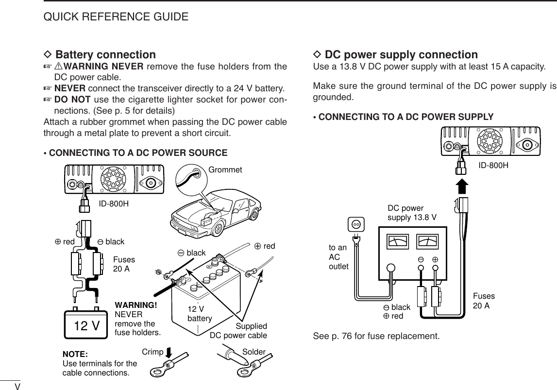
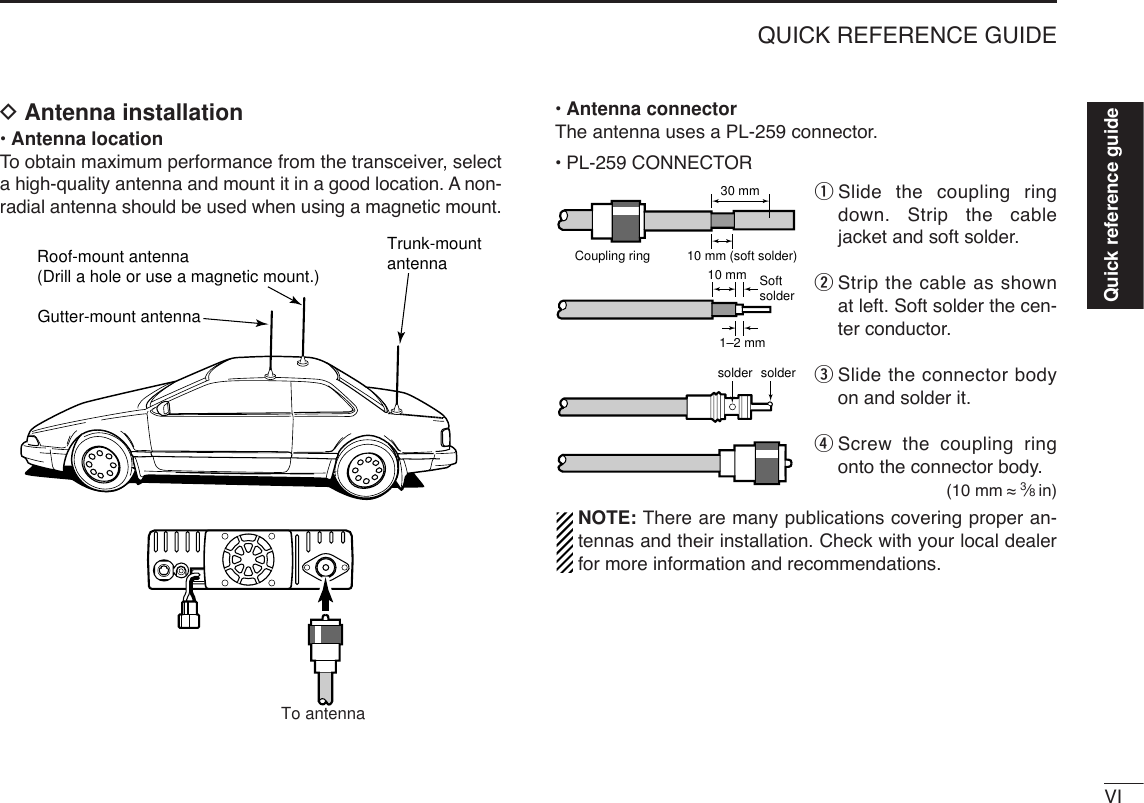
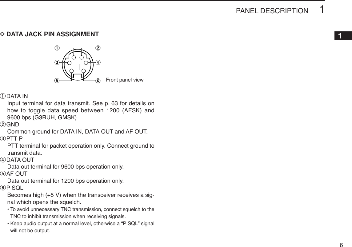
![51PANEL DESCRIPTION■Rear PanelqDATA SOCKET [DATA]Connects a TNC (Terminal Node Controller), etc. for datacommunications.•See p. 6 for connection information.wEXTERNAL SPEAKER JACK [SP]Connects an 8 Ωspeaker.•Audio output power is more than 2.0 W.eCOOLING FAN Rotates while transmitting. Also rotates while receiving depending on the setting in ini-tial set mode. (p. 63)rANTENNA CONNECTOR [ANT]Connects a 50 Ωantenna with a PL-259 connector and a50 Ωcoaxial cable.tPOWER RECEPTACLE [DC13.8V]Accepts 13.8 V DC ±15% with the supplied DC powercable.☞NOTE: DO NOT use a cigarette lighter socket as apower source when operating in a vehicle. The plugmay cause voltage drops and ignition noise may be su-perimposed onto transmit or receive audio.ANTENNA INFORMATIONFor radio communications, the antenna is of critical impor-tance, to maximize your output power and receiver sensi-tivity. The transceiver accepts a 50 Ωantenna and lessthan 1:1.5 of Voltage Standing Wave Ratio (VSWR). HighSWR values not only may damage the transceiver but alsolead to TVI or BCI problems.qwret](https://usermanual.wiki/ICOM-orporated/278800.Users-Manual-Part-1/User-Guide-473908-Page-20.png)
![71PANEL DESCRIPTION■Microphone (HM-133*)qVFO/LOCK SWITCH [VFO/LOCK]➥Push to select VFO mode. (p. 11)➥Push for 1 sec. to switch the lock function ON and OFF.(p. 14)wPTT SWITCH➥Push and hold to transmit; release to receive.➥Switches between transmitting and receiving while theone-touch PTT function is in use. (p. 18)eUP/DOWN SWITCHES [Y]/[Z]➥Push either switch to change operating frequency,memory channel, set mode setting, etc. (pgs. 12, 26, 56)➥Push either switch for 1 sec. to start scanning. (p. 41)rACTIVITY INDICATOR➥Lights red while any key, except [FUNC] and [DTMF-S],is pushed, or while transmitting.➥Lights green while the one-touch PTT function is in use.tKEYPAD (pgs. 8, 9)yFUNCTION INDICATOR➥Lights orange while [FUNC] is activated—indicates thesecondary function of switches can be accessed.➥Lights green when [DTMF-S] is activated—DTMF sig-nals can be transmitted with the keypad.u2nd FUNCTION SWITCH [FUNC] iDTMF SELECT SWITCH [DTMF-S] (p. 50)oFUNCTION SWITCHES [F-1]/[F-2] (p. 67)Program and recall your desired transceiver conditions.!0BAND SWITCH [BAND] ➥Push to select the frequency band. (p. 11)➥Push for 1 sec. to select the operating mode. (p. 65)!1MEMORY/CALL SWITCH [MR/CALL]➥Push to select memory mode. (p. 11)➥Push for 1 sec. to select call channel. (p. 38)Mic elementqertwyuio!0!1*Adifferent microphonemay be supplied de-pending on version.](https://usermanual.wiki/ICOM-orporated/278800.Users-Manual-Part-1/User-Guide-473908-Page-22.png)
![81PANEL DESCRIPTION1■Microphone keypadKEY FUNCTION SECONDARY FUNCTION ( +key) OTHER FUNCTIONSSwitches between opening and closing thesquelch. (p. 15)Starts and stops scanning. (p. 41)Starts and stops priority watch. (p. 47)Selects high output power. (p. 17)Selects mid. output power. (p. 17)Selects low output power (p. 17)Selects minus duplex operation. (p. 21)Selects plus duplex operation. (p. 21)Selects simplex operation. (p. 21)Increases audio output level. (p. 15)In memory mode enters bank selectingcondition. (p. 35)Starts and stops tone scanning. (p. 55)Turns the one-touch PTT function ON andOFF. (p. 18)Turns the DTCS squelch ON. (p. 54)Turns the DTCS pocket beep function ON.(p. 53)Turns the DTMF memory encoder functionON. (p. 50)Turns the subaudible tone encoder ON.(p. 21)Turns the CTCSS pocket beep functionON. (p. 53)Turns the tone squelch function ON.(p. 54)Sends a 1750 Hz tone signal while pushingand holding. (p. 23)After pushing :Transmits the appropriateDTMF code. (pgs. 23, 50)When the DTMF memory en-coder is activated, push [0] to[9] to transmit the appropriateDTMF memory contents.(p. 50)](https://usermanual.wiki/ICOM-orporated/278800.Users-Manual-Part-1/User-Guide-473908-Page-23.png)
![101PANEL DESCRIPTION1■Optional Microphones(HM-118N/TN/TAN)qPTT SWITCHPush and hold to transmit; release to receive.wUP/DOWN SWITCHES [UP]/[DN]➥Push either switch to change operating frequency,memory channel, set mode setting, etc. (pgs. 12, 26, 56)➥Push either switch for 1 sec. to start scanning. (p. 41)eUP/DN LOCK SWITCHSlide to toggle [UP]/[DN] switches function ON and OFF.rKEYPAD (HM-118TN/TAN only)While pushing [PTT], push the desired key to send theDTMF code.wqONOFFewrqONOFFe• HM-118N• HM-118TN/TAN (DTMF)](https://usermanual.wiki/ICOM-orporated/278800.Users-Manual-Part-1/User-Guide-473908-Page-25.png)
![11SETTING A FREQUENCY2■PreparationDTurning power ON/OFF➥Push [PWR] for 1 sec. to turn power ON and OFF.DOperating frequency band selectionThe ID-800H has 2 m and 70 cm bands for transmission andreception. In addition, extra frequency bands 127, 220, 350,500 and 900 MHz bands are available for wide-band receivercapability (except Taiwan and Korean version).➥Push [BAND] to select the desired frequency band.➥Push [BAND] to select the desired band.DVFO and memory modesThe transceiver has 2 basic operating modes: VFO mode andmemory mode. Select VFO mode first to set an operating fre-quency.➥Push [V/MHz•SCAN] to select VFO mode.•When VFO mode is already selected, the digit below 10 MHz(the digit below 1 MHz or 100 kHz disappear depending on ver-sions) disappear. In this case, push [V/MHz•SCAN] again (ortwice or 3 times depending on version).➥Push [M/CALL•PRIO] to select memory mode.•“!” indicator appears when memory mode is selected.➥Push [VFO/LOCK] to select VFO mode.➥Push [MR/CALL] to select memory mode.VFO/LOCK[V/MHz•SCAN][M/CALL•PRIO] AppearsBAND[BAND][PWR]Note that in this manual, sections beginning with a micro-phone icon (as above), designate operation via the HM-133microphone.](https://usermanual.wiki/ICOM-orporated/278800.Users-Manual-Part-1/User-Guide-473908-Page-26.png)
![122SETTING A FREQUENCY2■Using the tuning dialqRotate [DIAL] to set the frequency.•If VFO mode is not selected, push [V/MHz•SCAN] to select VFOmode.•The frequency changes in the selected tuning steps. (p. 13)wTo change the frequency in 1 MHz (10 MHz for some versions)steps, push [V/MHz•SCAN], then rotate [DIAL].•Pushing [V/MHz•SCAN] for 1 sec. starts scan function. If scanstarts, push [V/MHz•SCAN] again to cancel it.■Using the [Y]/[Z] keys➥Push [Y] or [Z] to select the desired frequency.•Pushing [Y]/[Z] for 1 sec. activates a scan. If scanstarts, push [Y]/[Z] or [CLRA(MW)] to cancel it.■Using the keypadThe frequency can be directly set via numeral keys on the mi-crophone.zPush [VFO/LOCK] to select VFO mode, if neces-sary.xPush [ENTC(T-OFF)] to activate the keypad fordigit input.cPush 6 keys to input a frequency.•When a digit is mistakenly input, push [ENTC(T-OFF)]to clear the input, then repeat input from the 1st digit.•Pushing [CLRA(MW)] clears input digits and retrievesthe frequency.PushPushPushPush[EXAMPLE]: Setting frequency to 145.3625 MHz.ENTCYZWhile 1 MHz tuning step is selected, the digit below 100 kHz disappear.While 10 MHz tuning step is selected, the digit below 1 MHz disappear.[DIAL][V/MHz•SCAN]](https://usermanual.wiki/ICOM-orporated/278800.Users-Manual-Part-1/User-Guide-473908-Page-27.png)
![132SETTING A FREQUENCY■Tuning step selection[Tuning steps are the minimum frequency change incrementswhen you rotate [DIAL] or push [Y]/[Z] on the microphone.Independent tuning step for each frequency bands can be setfor individual tuning convenience. The following tuning stepsare available.•5kHz • 10 kHz • 12.5 kHz • 15 kHz•20kHz •25kHz • 30 kHz • 50 kHz•100 kHz • 200 kHz☞NOTE: For convenience, select a tuning step that matchesthe frequency intervals of repeaters in your area.qPush [BAND] to select the desired frequency band.•Push [V/MHz•SCAN] to select VFO mode, if necessary.wPush [SET•LOCK] to enter set mode.•Rotate [DIAL] to select “SET,” if necessary.ePush [SET•LOCK] or [S.MW•MW] several times until “TS”appears as shown below.rRotate [DIAL] to select the desired tuning step.tPush [V/MHz•SCAN] to exit set mode.zPush [BAND] to select the desired frequencyband.•Push [VFO/LOCK] to VFO mode, if necessary.xPush [SETB(D-OFF)] to enter set mode.•Push [Y] or [Z]to select “SET,” if necessary.cPush [SETB(D-OFF)] or [ENTC(T-OFF)] severaltimes until “TS” appears.vPush [Y] or [Z] to select the desired tuning step.bPush [CLRA(MW)] to exit set mode.SETB[SET•LOCK]](https://usermanual.wiki/ICOM-orporated/278800.Users-Manual-Part-1/User-Guide-473908-Page-28.png)
![142SETTING A FREQUENCY2■Lock functionsTo prevent accidental frequency changes and unnecessaryfunction access, use the lock function. The transceiver has 2different lock functions.DFrequency lockThis function locks [DIAL] and switches electronically and canbe used together with the microphone lock function.➥Push [SET•LOCK] for 1 sec. to turn the lock function ONand OFF.•[PTT], [MONI•DTMF] (monitor function only), [VOL] and [SQL]can be used while the channel lock function is in use. Also,TONE-1, TONE-2, DTMF tones or DTMF memory contents canbe transmitted from the microphone.➥Push [VFO/LOCK] for 1 sec. to switch thelock function ON and OFF.DMicrophone keypad lockThis function locks the microphone keypad.➥Push [FUNC] then [SQLZD(16KEY-L)] toswitch the microphone keypad lock functionON and OFF.•[PTT], [VFO/LOCK], [MR/CALL], [BAND], [Y], [Z],[F-1], [F-2] and [FUNC] on the microphone can beused.•All switches on the transceiver can be used.•The keypad lock function is released when thepower is turned OFF then ON again.16KEY-LVFO/LOCK[SET•LOCK]“L” appears](https://usermanual.wiki/ICOM-orporated/278800.Users-Manual-Part-1/User-Guide-473908-Page-29.png)
![15BASIC OPERATION3■ReceivingqSet the audio level.➥Push [MONI•DTMF] to open the squelch.➥Rotate [VOL] to adjust the audio level.➥Push [MONI•DTMF] to close the squelch.wSet the squelch level.➥Rotate [SQL] fully counterclockwise in advance, then ro-tate [SQL] clockwise until the noise just disappears.•When interference is received, rotate [SQL] clockwise againfor attenuator operation. (p. 16)eSet the operating frequency. (pgs. 11, 12)rWhen receiving a signal on the set frequency, squelchopens and the transceiver emits audio.•“BUSY” appears and the S/RFindicator shows the relativesignal strength for the re-ceived signal.✔CONVENIENT!The audio and squelch level can also be adjustedwith [VOLY(TONE-1)]/[VOLZ0(TONE-2)] and[SQLYD(MUTE)]/[SQLZ#(16KEY-L)], respectively.•“VOL” for audio or “SQL” for squelch appears during set.■Monitor functionThis function is used to listen to weak signals without disturb-ing the squelch setting. ➥Push [MONI•DTMF] to open the squelch.•“BUSY” blinks.•Push [MONI•DTMF] again to cancel the function.➥Push [MONI1(BANK)] to open the squelch.•Push [MONI1(BANK)] again to cancel the function.NOTE: When [SQL] adjustment is set too far clockwise,(12–17 o’clock position) the squelch attenuator is acti-vated. To monitor weak signals on the operating frequency,deactivate the squelch attenuator function. See p. 16 fordetails.MONI1[MONI•DTMF] BlinksShow set levelSQLY/ZD/#VOLY/ZM/0Appears when receiving a signal](https://usermanual.wiki/ICOM-orporated/278800.Users-Manual-Part-1/User-Guide-473908-Page-30.png)
![163BASIC OPERATION3■Squelch attenuatorThe transceiver has an RF attenuator related to the squelchlevel setting. Approx. 10 dB attenuation is obtained at maxi-mum setting. The squelch attenuator allows you to set a minimum signallevel needed to open the squelch. The attenuator function canbe deactivated in initial set mode.➥Rotate [SQL] clockwise past the 12 o’clock position to ac-tivate the squelch attenuator.•Attenuation level can be adjusted up to 10 dB (approx.) between12 o’clock and fully clockwise position.•When setting the squelch from the microphone, a level greaterthan ‘19’ activates the squelch attenuator.NOTE: The squelch attenuator functions even when themonitor function is in use. Thus set [SQL] control within 10to 12 o’clock position is recommended when using themonitor function.DSquelch attenuator settingqTurn the transceiver power OFF.wWhile pushing [SET•LOCK], turn the power ON to enter ini-tial set mode.ePush [SET•LOCK] or [S.MW•MW] to select “ATT” (squelchattenuator) item.rRotate [DIAL] to toggle the function ON and OFF.•Select “OF” to deactivate the squelch attenuator function.tPush [PWR] to exit initial set mode.[PWR][SET•LOCK]USINGINITIAL SET MODESquelch isopen.SquelchattenuatorSquelch threshold Shallow DeepNoise squelch](https://usermanual.wiki/ICOM-orporated/278800.Users-Manual-Part-1/User-Guide-473908-Page-31.png)
![173BASIC OPERATION■Transmitting☞NOTE: To prevent interference, listen on the channel be-fore transmitting by pushing [MONI•DTMF] on the frontpanel or [MONI1(BANK)] on the microphone.qSelect the frequency band. (p. 11)wSet the operating frequency. (pgs. 11, 12)•Select output power if desired. See section at right for details.ePush and hold [PTT] to transmit.•“$” appears.•The S/RF indicator shows the output power selection.•Aone-touch PTT function is available. See p. 18 for details.rSpeak into the microphone using your normal voice level.•DO NOT hold the microphone too close to your mouth or speaktoo loudly. This may distort the signal.tRelease [PTT] to return to receive.■Selecting output powerThe transceiver has 3 output power levels to suit your oper-ating requirements. Low output powers during short-distancecommunications may reduce the possibility of interference toother stations and will reduce current consumption.➥Push [LOW•DUP] once or twice to select the output power.*approx •The output power can be changed while transmitting.The microphone can also be used to select output power.➥Push [HIGH4(DTCS)] for high output power;[MID5(DTCSS)] for middle output power; and[LOW6(DTMF)] for low output power.•The output power can be changed via the microphoneduring receive only.HIGH4MID5LOW6IMPORTANT! (for 55/50 W transmission):The ID-800H is equipped with protection circuit to protectthe power amplifier circuit from high SWR (Standing WaveRatio) and temperature. When a high SWR antenna or noantenna is connected, or when the transceiver temperaturebecomes extremely high, the transceiver reduces transmitoutput power to 15 W (approx.) automatically. CAUTION: Transmitting without an antenna will damagethe transceiver.S/RF INDICATOR POWER OUTPUTVHF UHF55 W 50 W15 W* 15 W*5W* 5W*High:Mid:Low:](https://usermanual.wiki/ICOM-orporated/278800.Users-Manual-Part-1/User-Guide-473908-Page-32.png)
![■One-touch PTT functionThe PTT switch can be operated as a one-touch PTT switch(each push toggles between transmit/receive). Using thisfunction you can transmit without pushing and holding thePTT switch.To prevent accidental, continuous transmission with this func-tion, the transceiver has a time-out timer. See p. 62 for de-tails.zPush [FUNC] then [PRIO3(PTT-M)] to turn theone-touch PTT function ON.•The activity indicator lights green.xPush [PTT] to transmit and push again to re-ceive.•Abeep sounds when transmission is started and along beep sounds when returning to receive.•“$” blinks when transmitting with the one-touchPTT function.cPush [FUNC] then [PRIO3(PTT-M)] to turn theone-touch PTT function OFF.•The activity indicator goes out.■Audio mute functionThis function temporarily mutes the audio without disturbingthe volume setting.➥Push [FUNC] then [SQLYD(MUTE)] to muteaudio signals.•The audio mute indicator, “ ” appears.•Push [CLRA(MW)] (or any other key) to cancel thefunction.AppearsMUTEindicator blnksPTT-M183BASIC OPERATION3](https://usermanual.wiki/ICOM-orporated/278800.Users-Manual-Part-1/User-Guide-473908-Page-33.png)
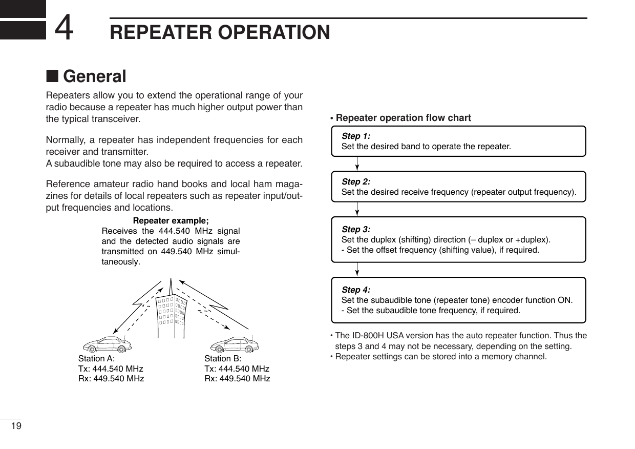
![204REPEATER OPERATION4■Accessing a repeaterqSet the receive frequency (repeater output frequency).(pgs. 11, 12)wPush [LOW•DUP] for 1 sec. one or two times, to selectminus duplex or plus duplex.•“DUP–” or “DUP” appears to indicate the transmit frequency forminus shift or plus shift, respectively.•When the auto repeater function is turned ON (available for theUSA version only), steps wand eare not necessary. (p. 25)ePush [TONE•T-SCAN] several times to turn ON the sub-audible tone encoder, according to repeater requirements.•“T” appears •88.5 Hz is set as the default; refer to p. 22 for tone frequencysettings.•When the repeater requires a different tone system, see p. 23.rPush and hold [PTT] to transmit.•The displayed frequency automatically changes to the transmitfrequency (repeater input frequency).•If “OFF” appears, confirm that the offset frequency (p. 24) is setcorrectly.tRelease [PTT] to receive.yPush [MONI•DTMF] to check whether the other station’stransmit signal can be received directly.uTo return to simplex operation, push [LOW•DUP] once ortwice, to clear the “DUP–” or “DUP” indicator.iTo turn OFF the subaudible tone encoder, push [TONE•T-SCAN] several times until no tone indicators appear.While transmittingWhile receiving[TONE•T-SCAN] “T” appears[LOW•DUP] “DUP–” or “DUP” appears](https://usermanual.wiki/ICOM-orporated/278800.Users-Manual-Part-1/User-Guide-473908-Page-35.png)
![214REPEATER OPERATIONzSet the receive frequency (repeater output fre-quency). (pgs. 11, 12)xPush [DUP–7(TONE)] to select minus duplex;push [DUP+8(TSQLS)] to select plus duplex.cPush [FUNC] then [DUP–7(TONE)] to turn ONthe subaudible tone encoder according to re-peater requirements.•Refer to p. 22 for the tone frequency setting.•When the repeater requires a different tone system,see p. 23.vPush and hold [PTT] to transmit.bRelease [PTT] to receive.nPush [MONI1(BANK)] to check whether theother station’s transmit signal can be receiveddirectly.mPush [SIMP9(TSQL)] to return to simplex opera-tion.•“DUP” or “DUP–” indicator disappears.,To turn OFF the subaudible tone encoder, push[FUNC] then [ENTC(T-OFF)].SIMP9Push ,then .PushPushDUP–7DUP+8](https://usermanual.wiki/ICOM-orporated/278800.Users-Manual-Part-1/User-Guide-473908-Page-36.png)
![224REPEATER OPERATION4■Subaudible tones [(Encoder function)DSubaudible tonesqSelect the frequency band, mode/channel you wish to setthe subaudible tones, such as VFO mode or memory/callchannel.wPush [SET•LOCK] to enter set mode.•Rotate [DIAL] to select “SET,” if necessary.ePush [SET•LOCK] or [DUP•MONI] several times until “T”and “rT” appear; or until “T SQL” and “CT” appear for tonesquelch or pocket beep use.•When “d” is displayed in place of the 100 MHz digit, cancel theDTMF memory encoder in advance. (p. 50)rRotate [DIAL] to select and set the desired subaudible fre-quency.tPush [V/MHz•SCAN] to exit set mode.☞NOTE: The subaudible tone encoder frequency can be setin a memory/call channel temporarily. However, the set fre-quency is cleared once another memory channel or VFOmode is selected. To store the tone frequency permanently,overwrite the channel information.zSet the frequency band, mode/channel you wishto set the subaudible tones, such as VFO modeor memory/call channel.•The subaudible tone frequency is independently pro-grammed into each mode or channel.xPush [SETB(D-OFF)] to enter set mode.•Push [Y] or [Z] to select “SET,” if necessary.cPush [SETB(D-OFF)] or [ENTC(T-OFF)] severaltimes until “T”and “rT” appears; or until “T SQL”and “CT” appears for tone squelch or pocketbeep use.•When “d” is displayed in place of the 100 MHz digit,cancel the DTMF memory encoder in advance. (p. 50)vPush [Y] or [Z] to select and set the desiredsubaudible tone frequency.•Push and hold [Y]/[Z] to change the above tonescontinuously.bPush [CLRA(MW)] to exit set mode.•Subaudible tone frequency list (unit: Hz)67.069.371.974.477.079.782.585.488.591.594.897.4100.0103.5107.2110.9114.8118.8123.0127.3131.8136.5141.3146.2151.4156.7159.8162.2165.5167.9171.3173.8177.3179.9183.5186.2189.9192.8196.6199.5203.5206.5210.7218.1225.7229.1233.6241.8250.3254.1Push SETB[SET•LOCK] “T” and “rT” appears](https://usermanual.wiki/ICOM-orporated/278800.Users-Manual-Part-1/User-Guide-473908-Page-37.png)
![DDTMF tones➥Push [DTMF-S], then push the keys of the de-sired DTMF digits.•The function indicator lights green.•0–9, A–D, M(E) and #(F) are available.•When “d” is displayed in place of the 100 MHz digit,cancel the DTMF memory encoder in advance.(p. 50)•Push [DTMF-S] again to return the keypad to nor-mal function control.✔For your convenient!The transceiver has 16 DTMF memory channels for au-topatch operation. See p. 48 for details.D1750 Hz toneThe microphone has 1750 Hz tone capability, used for ringtone when calling, etc.zPush [FUNC].•The function indicator lights orange.xPush [MM(TONE-1)] to transmit a 1750 Hz tonecall signal for 0.5 sec.; push and hold[0(TONE-2)] to transmit a 1750 Hz tone callsignal for an arbitrary period.•The function indicator goes out automatically.Push ,then or .TONE-1TONE-2then push desired keys.Push ,DTMF-S234REPEATER OPERATION](https://usermanual.wiki/ICOM-orporated/278800.Users-Manual-Part-1/User-Guide-473908-Page-38.png)
![244REPEATER OPERATION4■Offset frequency [When communicating through a repeater, the transmit fre-quency is shifted from the receive frequency by an amountdetermined by the offset frequency. Independent offset frequencies can be set for each operatingfrequency.qPush [BAND] to select the desired frequency band.wSelect the desired mode/channel you wish to set the offsetfrequency, such as VFO mode or memory/call channel.•The offset frequency can be independently programmed intoeach mode or channel.ePush [SET•LOCK] to enter set mode.•Rotate [DIAL] to select “SET,” if necessary.rPush [SET•LOCK] or [S.MW•MW] until “DUP” and offsetfrequency appear.tRotate [DIAL] to set the desired offset frequency.yPush [V/MHz•SCAN] to exit set mode.zPush [BAND] to select the desired frequencyband.•Enter the desired frequency via the keypad if neces-sary.xSelect the desired mode/channel you wish toset the offset frequency, such as VFO mode ormemory/call channel.•The offset frequency can be independently pro-grammed into each mode or channel.cPush [SETB(D-OFF)] to enter set mode.•Push [Y] or [Z]to select “SET,” if necessary.vPush [SETB(D-OFF)] or [ENTC(T-OFF)] until“DUP” and offset frequency appear.bPush [Y] or [Z] to set the desired offset.•Direct frequency entry from the keypad is not possi-ble.nPush [CLRA(MW)] to exit set mode.☞NOTE: The offset frequency can be set in a memory/callchannel temporarily. However, the set frequency is clearedonce another memory channel or VFO mode is selected.To store the offset frequency permanently, overwrite thechannel information.Push SETB[SET•LOCK] “DUP” and offset frequency appear](https://usermanual.wiki/ICOM-orporated/278800.Users-Manual-Part-1/User-Guide-473908-Page-39.png)
![■Auto repeater (U.S.A. version only)The USA version automatically activates the repeater settings(DUP– or DUP+ and tone encoder ON/OFF) when the operatingfrequency falls within the general repeater output frequencyrange and inactivate them when outside of the range.DSetting the auto repeater function ON/OFFqPush [PWR] to turn power OFF.wWhile pushing [SET•LOCK], turn power ON to enter initialset mode.ePush [SET•LOCK] or [S.MW•MW] several times until the“RPT” display appears as shown above right.rRotate [DIAL] to select the auto repeater function from“R1,” “R2” or OFF.•“R1”: auto repeater is ON, tone encoder is OFF.•“R2”: auto repeater is ON, tone encoder is ON.tPush [PWR] to exit initial set mode.DFrequency range and offset directionAuto DUP: ONAuto tone set: OFFAuto DUP: ONAuto tone set: ON[PWR][SET•LOCK]USINGINITIAL SET MODE254REPEATER OPERATIONFrequency range Duplex direction145.200–145.495 MHz “DUP–” appears146.610–146.995 MHz147.000–147.395 MHz “DUP” appears442.000–444.995 MHz “DUP” appears447.000–449.995 MHz “DUP–” appears](https://usermanual.wiki/ICOM-orporated/278800.Users-Manual-Part-1/User-Guide-473908-Page-40.png)
![265MEMORY OPERATION45■General descriptionThe transceiver has 512 memory channels including 10 scanedge memory channels (5 pairs), and 2 call channels. Each ofthese channels can be individually programmed with operat-ing frequency (pgs. 11, 12), duplex direction (p. 21) and off-set (p. 24), subaudible tone encoder or tone squelch and itstone frequency (pgs. 20, 22, 52, 53) and skip information*(p. 44). In addition, a total of 10 memory banks, A to J, are availablefor usage by group, etc.*except for scan edge memory channels.■Memory channel selectionDUsing the tuning dialqPush [M/CALL•PRIO] several times to select memorymode.•“!” indicator appearswRotate [DIAL] to select the desired memory channel.•Programmed memory channels only can be selected.DUsing the [Y]/[Z] keyszPush [MR/CALL] to select memory mode.xPush [Y] or [Z] to select and set the desiredmemory channel.•Pushing [Y]/[Z] for 1 sec. activates a scan.•If scan is activated, push [Y]/[Z] again or push[CLRA(MW)] to stop it.DUsing the keypadzPush [MR/CALL] to select memory mode.xPush [ENTC(T-OFF)] to activate the keypadfor numeral input.cPush 3 appropriate digit keys to input a chan-nel number. •Blank channel can be selected.•Push only 1 appropriate digit key, [MONI1(BANK)],[SCAN2(T-SCAN)], [PRIO3(PTT-M)],[HIGH4(DTCS)] or [MID5(DTCSS)] then push[MM(TONE-1)] or [SQLZ#(16KEY-L)] to select scanedge channels. “MM” and “#” can be used for “A”and “b” respectively.MR/CALLMR/CALLY/Z[M/CALL•PRIO] “!” appears](https://usermanual.wiki/ICOM-orporated/278800.Users-Manual-Part-1/User-Guide-473908-Page-41.png)
![275MEMORY OPERATION■Programming a memory channel[EXAMPLE]: Programming 145.870 MHz into memory channel 20 (blank channel) via the controller.Push Rotate for setting frequency, etc. Push .Rotate Push for 1 sec. and continue to push ➠Beep“BeepBeepBeep“““““Beep“VFO settings, including the set mode contents such as sub-audible tone frequency or offset, can be programmed into amemory channel.qSet the desired frequency. ➥Push [V/MHz•SCAN] to select VFO mode.➥Set the frequency using [DIAL].➥Set other data (e.g. tone frequency, duplex information,etc.) if required.wPush [S.MW•MW].•“!” indicator and the memory channel number blink.eRotate [DIAL] to select the memory channel to be pro-grammed.•Memory channels not yet programmed are blank.rPush [S.MW•MW] for 1 sec. to program.•3 beeps sound•Memory channel number automatically increases when contin-uing to push [S.MW•MW] after programming.✔CONVENIENTMemory programming can be performed in versatile wayse.g. memory channel to the same (or different) memory chan-nel, memory channel to the call channel, etc.](https://usermanual.wiki/ICOM-orporated/278800.Users-Manual-Part-1/User-Guide-473908-Page-42.png)
![285MEMORY OPERATION5DProgramming a memory channel via the microphone[EXAMPLE]: Programming 145.870 MHz into memory channel 20 (blank channel) via the microphone.Push 10 timesBeep“Beep“BeepBeepBeep“““““Push Push thenPush then for 1 sec. and continue to push ➠The microphone can also be used to program mem-ory channels.zSet the desired frequency in VFO mode.➥Push [VFO/LOCK] to select VFO mode.➥Set the frequency using the keypad.➥Set other data (e.g. offset frequency, duplex direction, sub-audible tone encoder ON/OFF and its frequency), if neces-sary.xPush [FUNC] then [CLRA(MW)] momentarily.cPush [Y] or [Z] to select the memory channel.•Direct numeral input cannot be used.vPush [FUNC] then [CLRA(MW)] for 1 sec. to program.➥3 beeps may sound and the VFO contents (includingthe subaudible tone frequency, etc.) are programmed.➥Memory channel number increases when continuing topush [CLRA(MW)] after programming.MW](https://usermanual.wiki/ICOM-orporated/278800.Users-Manual-Part-1/User-Guide-473908-Page-43.png)
![295MEMORY OPERATION■Copying memory contentsThis function copies a memory channel’s contents to VFO (oranother memory/call channel). This is useful when searchingfor signals around a memory channel frequency and for re-calling the offset frequency, subaudible tone frequency etc.DMemory/call➪VFOqSelect the desired memory or call channel.➥Push [M/CALL•PRIO] several times to select memorymode or call channel, then rotate [DIAL] or push [BAND]to select the desired memory or call channel respec-tively.wPush [S.MW•MW] for 1 sec. to transfer the selected mem-ory/call channel contents to the VFO.•VFO mode is selected automatically.zSelect the memory/call channel to betransferred.➥Push [MR/CALL] to select memory mode,then select the desired memory channelvia [Y]/[Z] or keypad.➥Push [MR/CALL] for 1 sec. then push[BAND] to select the desired call channel.xPush [FUNC], then [CLRA(MW)] for 1 sec. totransfer the selected memory/call channelcontents to the VFO.•VFO mode is selected automatically.MR/CALLMWBAND[Y]/[Z][EXAMPLE]: Transferring memory channel 30 contents to VFO.Push to select memory mode.Front panel operation:HM-133 operation:Push to select memory mode.Rotate for selecting memory channel.Push [Y]/[Z] to select memory channel.Push for 1 sec.Push then push for 1 sec.](https://usermanual.wiki/ICOM-orporated/278800.Users-Manual-Part-1/User-Guide-473908-Page-44.png)
![305MEMORY OPERATION5DMemory/call➪memory/callqSelect the memory/call channel to be transferred.➥Push [M/CALL•PRIO] several times to select memorymode or call channel, then rotate [DIAL] or push [BAND]to select the desired memory or call channel respec-tively.wPush [S.MW•MW] momentarily.•“!” indicator and “-- -- --” indication blink, and shows VFO con-ditions.eRotate [DIAL] to select the target memory channel.•“C1” or “C2” blinks when the call channel is selected.•Scan edge channels, 1A/1B, 2A/2B, 3A/3B, 4A/4B, 5A/5B canalso be selected.rPush [S.MW•MW] for 1 sec. to transfer the selected mem-ory/call channel contents to the target memory.•The targeted memory and transferred contents are indicated.zSelect the memory/call channel to be trans-ferred.➥Push [MR/CALL] to select memory mode,then select the desired memory channelvia [Y]/[Z] or keypad.➥Push [MR/CALL] for 1 sec. then push[BAND] to select the desired call channel.xPush [FUNC], then [CLRA(MW)] momentarily.•“!” indicator and “-- -- --” indication blink, andshows VFO conditions.cPush [Y]/[Z] to select the target memorychannel.•“C1” or “C2” blinks when the call channel is selected.•Scan edge channels can also be selected.•The keypad cannot be used for the selection.vPush [FUNC] then push [CLRA(MW)] for1sec. to transfer the selected memory/callchannel contents to the target channel.•The targeted channel and transferred contentsare indicated.MR/CALLMWBAND[Y]/[Z][EXAMPLE]: Transferring memory channel 30 contents to channel 31.Select the target channel. Push for 1 sec.Push then push for 1 sec.Select the memory channel, then push .Select the memory channel, push then push .Front panel operation:HM-133 operation:](https://usermanual.wiki/ICOM-orporated/278800.Users-Manual-Part-1/User-Guide-473908-Page-45.png)
![315MEMORY OPERATION■Programming channel names Each memory channel and the call channel can be pro-grammed with an alphanumeric channel name for easyrecognition and can be indicated independently by channel.Names can be a maximum of 6 characters— see the tablebelow for available characters.qPush [S.MW•MW] momentarily.•“!” and memory channel number blink.wRotate the tuning dial to select the desired memory or callchannel.ePush [BAND] to select the memory name programmingcondition.•Frequency readouts disappear and a cursor blinks.rRotate the tuning dial to select the desired character.•The selected character blinks.tPush [SET•LOCK] to move the cursor to the right.yRepeat steps rand tuntil the desired channel namesare displayed.uPush [S.MW•MW] for 1 sec. to program the name and exitthe channel name programming condition.(1)(B)(L)(V)(+)(2)(C)(M)(W)(–)(3)(D)(N)(X)(=)(4)(E)(O)(Y)(✱)(5)(F)(P)(Z)(/)(6)(G)(Q)(space)(7)(()(H)(R)())(8)(I)(S)(|)(9)(J)(T)(0)(A)(K)(U)[EXAMPLE]: Programming “CLUB” into memory channel 1.RotatePush Push RotatePush for 1 sec.Repeat theprevioussteps.BeepBeepBeep“““““Push](https://usermanual.wiki/ICOM-orporated/278800.Users-Manual-Part-1/User-Guide-473908-Page-46.png)
![325MEMORY OPERATION5Channel names can also be programmed via the mi-crophone.zPush [FUNC] then [CLRA(MW)] momentarily.•“!” and memory channel number blink.xPush [Y]/[Z] to select the memory/call channel to be as-signed memory names.cPush [BAND].•Frequency readouts disappear and a cursor blinks.vPush [Y]/[Z] to select the desired character.•The selected character blinks.bPush [SETB(D-OFF)] or [ENTC(T-OFF)] to move the cur-sor to left or right, respectively.nRepeat steps vand buntil the desired channel namesare displayed.mPush [FUNC] then [CLRA(MW)] for 1 sec. to program thename and exit the channel name programming condition.[EXAMPLE]: Programming “CLUB” into memory channel 1.PushRepeat theprevioussteps.BeepBeepBeep“““““Push to select the channel. Push to select the characterPush or to move the cursor.Push , then push .Push , then push for 1 sec.](https://usermanual.wiki/ICOM-orporated/278800.Users-Manual-Part-1/User-Guide-473908-Page-47.png)
![5MEMORY OPERATION33DDTo indicate the channel name [The channel name indication can be set for independentmemory channels.qPush [M/CALL•PRIO] to select the memory mode.wRotate [DIAL] to select the desired memory channel to beindicated the channel name.ePush [SET•LOCK] to enter set mode.•Rotate [DIAL] to select “SET,” if necessary.rPush [SET•LOCK] or [S.MW•MW] several times to select“ANM” item.tRotate [DIAL] to turn the memory name indication ON.yPush [V/MHz•SCAN] to exit set mode.NOTE: When no memory name is programmed, the storedfrequency is displayed.zPush [MR/CALL] to select the memory mode.xPush [Y] or [Z] to select the desired memorychannel to be indicated the channel name.cPush [SETB(D-OFF)] to enter set mode.•Push [Y] or [Z]to select “SET,” if necessary.vPush [SETB(D-OFF)] or [ENTC(T-OFF)] until“ANM” appear.bPush [Y] or [Z] to set the memory name indi-cation ON and OFF.nPush [CLRA(MW)] to exit set mode.Push SETB](https://usermanual.wiki/ICOM-orporated/278800.Users-Manual-Part-1/User-Guide-473908-Page-48.png)
![5MEMORY OPERATION345■Memory clearingContents of programmed memories can be cleared (blanked),if desired.qPush [V/MHz•SCAN] to select VFO mode.wPush [S.MW•MW] momentarily.•“!” indicator and the memory channel number blink.eRotate [DIAL] to select the memory channel to be cleared.•Memory channels not yet programmed are blank.rPush [S.MW•MW] momentarily, then push [S.MW•MW]again for 1 sec.☞This operation must be performed within 1.5 sec.•3 beeps sound, then the frequency is cleared.•“!” indicator and the channel number blink continuously.•When clearing the call channel, the current VFO conditions arere-programmed into the call channel automatically.tPush [V/MHz•SCAN] to return to VFO mode.☞NOTE: Be careful!— the contents of cleared memoriesCANNOT be recalled.[EXAMPLE]: Clearing memory channel 20.Push to select VFO. Rotate for selecting memory channel.Push .Push any switch, except .Push momentarily, then push again for 1 sec.BeepBeepBeep“““““](https://usermanual.wiki/ICOM-orporated/278800.Users-Manual-Part-1/User-Guide-473908-Page-49.png)
![355MEMORY OPERATION■Memory bank selectionThe ID-800H has a total of 10 banks (A to J). Regular memorychannels, 1 to 500, are assigned into the desired bank foreasy memory management.qPush [M/CALL•PRIO] several times to select memorymode, if desired.wPush [BAND] to select memory bank condition.•Bank’s initial blinkseRotate [DIAL] to select the desired bank, A to J.•Banks that have no programmed contents are skipped.rPush [BAND] to set the bank.•Bank’s initial stops blinking.tRotate [DIAL] to select the contents in the bank.•No channel numbers are displayed for memory bank operation.yTo return to regular memory condition, push [BAND] twice.zPush [MR/CALL] to select memory mode, if de-sired.xPush [FUNC] then [MONI1(BANK)] to selectmemory bank condition.•Bank’s initial blinkscPush [Y]/[Z] to select the desired bank, A to J.•Only programmed memory bank can be selected.vPush [CLRA(MW)] to set the bank.•Bank’s initial stops blinking.bPush [Y]/[Z] to select the desired contents inthe bank.•No channel numbers are displayed for memorybank operation.nTo return to regular memory condition, push[FUNC], [MONI1(BANK)] then push[CLRA(MW)].BANK[Y]/[Z][BAND] Bank initial blinks](https://usermanual.wiki/ICOM-orporated/278800.Users-Manual-Part-1/User-Guide-473908-Page-50.png)
![365MEMORY OPERATION5■Memory bank setting[qPush [M/CALL•PRIO] several times to select memorymode, then select the desired memory channel via [DIAL].wPush [SET•LOCK] to enter set mode.•Rotate [DIAL] to select “SET,” if necessary.ePush [SET•LOCK] or [S.MW•MW] several times until“BAK” appears.rRotate [DIAL] to select the desired bank to be set.tPush [V/MHz•SCAN] to exit set mode.zPush [MR/CALL] then select the desired mem-ory channel via [Y]/[Z] or keypad.xPush [SETB(D-OFF)] to enter set mode.•Push [Y] or [Z]to select “SET,” if necessary.cPush [SETB(D-OFF)] or [ENTC(T-OFF)] severaltimes until “BAK” appears.vPush [Y]/[Z] to select the desired bank to beset.bPush [CLRA(MW)] to set the channel into thebank and exit set mode.SETB[SET•LOCK] Bank’s initial blinks](https://usermanual.wiki/ICOM-orporated/278800.Users-Manual-Part-1/User-Guide-473908-Page-51.png)
![375MEMORY OPERATION■Transferring bank contents[Contents of programmed memory banks can be cleared ortransferred to another bank.INFORMATION: Even if the memory bank contents arecleared, the memory channel contents still remain pro-grammed.qSelect the desired bank contents to be transferred orerased.➥Push [M/CALL•PRIO] several times to select memorymode.➥Push [BAND] then rotate [DIAL] to select the desiredmemory bank.•Bank’s initial blinks.➥Push [BAND] to select the bank then rotate [DIAL] to se-lect the desired contents.•Bank’s initial stops blinking.wPush [SET•LOCK] to enter set mode.•Rotate [DIAL] to select “SET,” if necessary.ePush [SET•LOCK] or [S.MW•MW] several times until“BAK” appears.•The bank’s initial for the selected memory channel is displayed.rRotate [DIAL] to select the desired bank initial to transferor erase.•Select “-- --” indication when erasing the contents from the bank.tPush [V/MHz•PRIO] to set the bank and exit set mode.yRepeat steps qto rfor transferring or erasing an an-other banks contents.zSelect the desired bank contents to be trans-ferred or erased.➥Push [MR/CALL] to select memory mode.➥Push [FUNC], [MONI1(BANK)] then selectthe desired memory bank via [Y]/[Z].➥Push [CLRA(MW)] to select the bank thenselect the desired contents via [Y]/[Z].xPush [SETB(D-OFF)] to enter set mode.•Push [Y] or [Z]to select “SET,” if necessary.cPush [SETB(D-OFF)] or [ENTC(T-OFF)] severaltimes until “BAK” appears. vPush [Y]/[Z] to select the desired bank initial totransfer or erase.•Select “-- --” indication when erasing the contentsfrom the bank.bPush [CLRA(MW)] to set the bank and exit setmode.nRepeat steps zto bfor transferring or eras-ing an another banks contents.BANK[Y]/[Z]SET](https://usermanual.wiki/ICOM-orporated/278800.Users-Manual-Part-1/User-Guide-473908-Page-52.png)
![386CALL CHANNEL OPERATION56■Call channel selectionCall channel is pre-programmed memory channel that can beaccessed by simply pushing call channel button.➥Push [M/CALL•PRIO] several times to select the call chan-nel mode then push [BAND] to select the desired callchannel.•“C1” or “C2” appears instead of memory channel number indi-cation.•Push [M/CALL•PRIO] several times to select memory mode, orpush [V/MHz•SCAN] to select VFO mode.➥Push [MR/CALL] for 1 sec. to select the callchannel mode then push [Y]/[Z] to select thedesired call channel in the main band.•Push [MR/CALL] to select memory mode, or push[VFO/LOCK] to select VFO mode.■Call channel transferringqPush [M/CALL•PRIO] several times then push [BAND] toselect the desired call channel.•“C1” or “C2” appears.wPush [S.MW•MW] then rotate [DIAL] to select the memorychannel to transfer the contents.•“!” indicator and memory channel number blink.•To transfer to the VFO, select “-- -- --” with [DIAL] then push. ePush [M/CALL•MW] for 1 sec. to transfer the contents.zPush [MR/CALL] for 1 sec. then push [BAND]to select the desired call channel.xPush [FUNC], [CLRA(MW)] momentarily, thenpush [Y]/[Z] to select the memory channel totransfer the contents.•To transfer to the VFO, push [Y]/[Z] to select “-- -- --”. cPush [FUNC], then [CLRA(MW)] for 1 sec. totransfer the contents.MR/CALLMWBAND[Y]/[Z]MR/CALL[M/CALL•PRIO] “C1” or “C2” appears✔INFORMATIONWhen the VFO mode is selec-ted from the call channel, a small “c” appears instead of memory channel number.](https://usermanual.wiki/ICOM-orporated/278800.Users-Manual-Part-1/User-Guide-473908-Page-53.png)
![396CALL CHANNEL OPERATION■Programming a call channelOperating frequency, duplex information, subaudible tone in-formation (tone encoder or tone squelch ON/OFF and its fre-quency) can be programmed into the call channel.qSet the desired frequency in VFO mode.➥Push [V/MHz•SCAN] to select VFO mode.➥Set the frequency using [DIAL].➥Set other data as desired.wPush [S.MW•MW] momentarily.eRotate [DIAL] to select the desired call channel.•“!” indicator and “C1” or “C2” blink.rPush [S.MW•MW] for 1 sec. to program.•3 beeps sound and the unit returns to VFO mode automatically.zSet the desired frequency in VFO mode.➥Push [VFO/LOCK] to select VFO mode.➥Set the frequency.➥Set other data as desired.xPush [FUNC], then [CLRA(MW)] momentarily.cSelect the call channel via [Y] or [Z].vPush [FUNC] then [CLRA(MW)] for 1 sec. toprogram.•3 beeps sound and the unit returns to VFO modeautomatically.MR/CALLMW[Y]/[Z][EXAMPLE]: Programming 145.120 MHz into the call channel 2 via the microphone.Set the frequency.Push to select VFO mode. Push , then .Push , then push for 1 sec. ➠Push until “C2” appears.BeepBeepBeep“““““](https://usermanual.wiki/ICOM-orporated/278800.Users-Manual-Part-1/User-Guide-473908-Page-54.png)
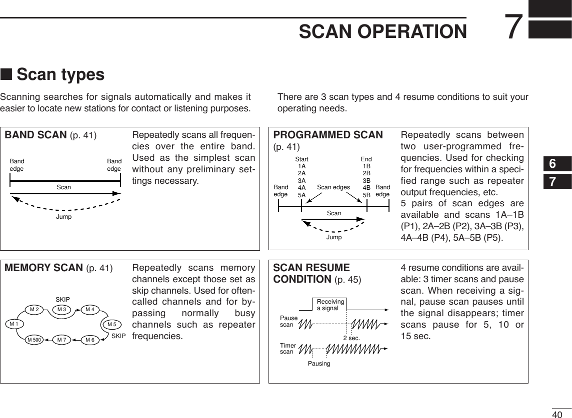
![417SCAN OPERATION■Scan start/stopDPreparationScan resume condition (p. 45); program the scan edges(pgs. 42, 43); program 2 or more memory channels (pgs. 27,28); set skip settings (p. 44), if desired.DOperationqSelect VFO mode for full/programmed scan with[V/MHz•SCAN]; or memory mode for memory scan with[M/CALL•PRIO].•Select the desired bank for bank scan.wSet the squelch to the point where noise is just muted.ePush [V/MHz•SCAN] for 1 sec. to start the scan.•To change the scanning direction, rotate [DIAL].•The memory channel readout blinks the scan type as follows:rPush [SET•LOCK] to switch full and programmed scan(P1, P2, P3, P4 and P5), if VFO is selected in step q.tTo stop the scan, push [V/MHz•SCAN].zPush [VFO/LOCK] to select VFO mode forfull/programmed scan; push [MR/CALL] to selectmemory mode for memory scan.•Push [FUNC] then [MONI1(BANK)] to select a bankfor bank scan.xPush [SQLYD(MUTE)] or [SQLZ#(16KEY-L)] toset the squelch to the point where noise is justmuted.cPush [SCAN2(T-SCAN)] to start the scan.•Push [Y] or [Z] for 1 sec. also starts the scan.vPush [SETB(D-OFF)] to switch full and pro-grammed scan (P1, P2, P3, P4 and P5), if VFOis selected in step z.bTo stop the scan push [SCAN2(T-SCAN)] or[CLRA(MW)].SCAN2SETB• During full scan • During programmed scan • During memory scan • During bank scanIndicates scan edge channels.• P1 stands for 1A/1B• P1 to P5 are available when they are programmed, and switches with [SET•LOCK].Indicates bank initial.Push [SET•LOCK] to select “ALL” (full) or programmed scan (P1, P2, P3, P4 and P5) in sequence.](https://usermanual.wiki/ICOM-orporated/278800.Users-Manual-Part-1/User-Guide-473908-Page-56.png)
![427SCAN OPERATION7■Scan edges programmingScan edges can be programmed in the same manner asmemory channels. Scan edges are programmed into scanedges, 1A/1B to 5A/5B, in memory channels.qSet the edge frequency of the desired frequency range inVFO mode:➥Set the frequency using [DIAL].➥Set other data (e.g. repeater settings, etc.) if desired.wPush [S.MW•MW].•“!” indicator and channel number blink.eRotate [DIAL] to select one of scan edge channel, 1A, 2A,3A, 4A or 5A.rPush [S.MW•MW] for 1 sec. to program.•3 beeps sound and VFO is automatically selected.•Scan edge 1B, 2B, 3B, 4B or 5B is automatically selected whencontinuing to push [S.MW•MW] after programming.tTo program a frequency for the other pair of scan edges,1B, 2B, 3B, 4B or 5B, repeat steps qto r.•If the same frequency is programmed into a pair of scan edges,programmed scan will not function.[EXAMPLE]: Programming 145.300 MHz into scan edges 1A.PushRotate for setting frequency, etc. RotatePush for 1 sec. and continue to push ➠BeepBeepBeep“Beep“““““](https://usermanual.wiki/ICOM-orporated/278800.Users-Manual-Part-1/User-Guide-473908-Page-57.png)
![437SCAN OPERATIONDProgramming scan edges via microphonezSet the desired frequency in VFO mode.➥Push [VFO/LOCK] to select VFO mode.➥Set the frequency via the keypad or [Y]/[Z].xPush [FUNC] then [CLRA(MW)] momentarily.cPush [Y] or [Z] to select scan edge channels,1A, 2A, 3A, 4A or 5A.vPush [FUNC], then push [CLRA(MW)] for 1 sec.to program.•3 beeps sound and VFO is automatically selected.•Memory channel number advances to the next scanedge channel, 1B, 2B, 3B, 4B or 5B when continuingto push [CLRA(MW)] after programming.bTo program a frequency for the other scan edge channels,repeat steps zto v.MW[EXAMPLE]: Programming 145.800 MHz into scan edge 1B.Push Push Push then momentarilyPush Push then for 1 sec. and continue to push ➠Beep“BeepBeepBeep“““““](https://usermanual.wiki/ICOM-orporated/278800.Users-Manual-Part-1/User-Guide-473908-Page-58.png)
![447SCAN OPERATION7■Skip channel setting[The memory skip function speeds up scanning by checkingonly those memory channels not set as skip channels. Setskip channels as follows.qSelect a memory channel:➥Push [M/CALL•PRIO] to select memory mode.➥Rotate [DIAL] to select the desired channel to be a skipchannel.wPush [SET•LOCK] to enter set mode.•Rotate [DIAL] to select “SET,” if necessary.ePush [SET•LOCK] or [S.MW•MW] several times until“CHS” appears as shown above.rRotate [DIAL] to turn the skip function ON or OFF for theselected channel.•“~” appears : The channel is skipped during scan. (CHS-ON)•“P~” appears : The channel is skipped during scan and theprogrammed frequency is skipped during VFO scan, such asprogrammed scan.(CHS-ON)•“~” disappears : The channel is scanned during scan.(CHS-OF)tPush [MONI•DTMF] to exit set mode.zSelect a memory channel.➥Select memory mode by pushing [MR/CALL].➥Push [Y] or [Z] to select the desired channelto be a skip channel.•Direct memory channel selection is also available.xPush [SETB(D-OFF)] to enter set mode.•Push [Y] or [Z] to select “SET,” if necessary.cPush [SETB(D-OFF)] or [ENTC(T-OFF)] severaltimes until “CHS” appears as shown at left.vPush [Y] or [Z] to set or cancel the skip setting.•See item rat left for skip indicator details.bPush [CLRA(MW)] to exit set mode.SETBThe display shows that mem-ory channel 1 is set as a skip channel.](https://usermanual.wiki/ICOM-orporated/278800.Users-Manual-Part-1/User-Guide-473908-Page-59.png)
![457SCAN OPERATION■Scan resume condition[The scan resume condition can be selected as timer or pausescan. The selected resume condition is also used for prioritywatch. (p. 47)qPush [SET•LOCK] to enter set mode.•Rotate [DIAL] to select “SET,” if necessary.wPush [SET•LOCK] or [S.MW•MW] several times until“SCT” or “SCP” appears as shown above.•When “d” is displayed in place of the 100 MHz digit, cancel theDTMF memory encoder in advance. (p. 50)eRotate [DIAL] to set the desired timer:•“SCT-15” : Scan pauses 15 sec. while receiving a signal.•“SCT-10” : Scan pauses 10 sec. while receiving a signal.•“SCT-5” : Scan pauses 5 sec. while receiving a signal.•“SCP-2” : Scan pauses until the signal disappears and thenresumes 2 sec. later.rPush [MONI•DTMF] to exit set mode.zPush [BAND] to select the desired band.xPush [SETB(D-OFF)] to enter set mode.•Push [Y] or [Z] to select “SET,” if necessary.cPush [SETB(D-OFF)] or [ENTC(T-OFF)] severaltimes until “SCT” or “SCP” appears as shown atleft.vPush [Y] or [Z] to select the scan resume condi-tion.•See item eat left for scan resume condition details.bPush [CLRA(MW)] to exit set mode.SETBThe display shows that the scan will resume 15 sec. after it stops.](https://usermanual.wiki/ICOM-orporated/278800.Users-Manual-Part-1/User-Guide-473908-Page-60.png)