ICOM orporated 278800 VHF/UHF Digital Transceiver User Manual ID 800H FCC
ICOM Incorporated VHF/UHF Digital Transceiver ID 800H FCC
Contents
- 1. Users Manual Part 1
- 2. Users Manual Part 2
Users Manual Part 1

INSTRUCTION MANUAL
ID-800H
VHF/UHF DIGITAL TRANSCEIVER
This device complies with Part 15 of the FCC rules. Operation is sub-
ject to the following two conditions: (1) This device may not cause
harmful interference, and (2) this device must accept any interference
received, including interference that may cause undesired operation.
i
FOREWORD
Thank you for purchasing this Icom product. The ID-800H
VHF
/
UHF DIGITAL TRANSCEIVER
is designed and built with Icom’s
state of the art technology and craftsmanship. With proper care,
this product should provide you with years of trouble-free oper-
ation.
We want to take a couple of moments of your time to thank
you for making your ID-800H your radio of choice, and hope
you agree with Icom’s philosophy of “technology first.” Many
hours of research and development went into the design of
your ID-800H.
DD
FEATURES
❍Switchable VHF and UHF transceiver
❍Selectable backlit color from amber, green
and yellow
❍Detachable controller for flexible installation
❍55 W* of high transmit output power
*VHF band; 50 W for UHF band
❍Remote control microphone standard
❍New DMS (Dynamic Memory Scan) system
IMPORTANT
READ ALL INSTRUCTIONS carefully and completely
before using the transceiver.
SAVE THIS INSTRUCTION MANUAL— This in-
struction manual contains important operating instructions for
the ID-800H.
EXPLICIT DEFINITIONS
WORD DEFINITION
RWARNING!
CAUTION
NOTE
Personal injury, fire hazard or electric shock
may occur.
Equipment damage may occur.
Recommended for optimum use. No risk of
personal injury, fire or electric shock.
Icom, Icom Inc. and the logo are registered trademarks of Icom
Incorporated (Japan) in the United States, the United Kingdom, Ger-
many, France, Spain, Russia and/or other countries.

RWARNING RF EXPOSURE! This device emits Radio
Frequency (RF) energy. Extreme caution should be observed when
operating this device. If you have any questions regarding RF expo-
sure and safety standards please refer to the Federal Communica-
tions Commission Office of Engineering and Technology’s report on
Evaluating Compliance with FCC Guidelines for Human Radio fre-
quency Electromagnetic Fields (OET Bulletin 65).
RWARNING! NEVER connect the transceiver to an AC out-
let. This may pose a fire hazard or result in an electric shock.
RWARNING! NEVER operate the transceiver while driving a
vehicle. Safe driving requires your full attention—anything less may
result in an accident.
NEVER connect the transceiver to a power source of more than
16 V DC. This will damage the transceiver.
NEVER connect the transceiver to a power source using reverse
polarity. This will damage the transceiver.
NEVER cut the DC power cable between the DC plug and fuse
holder. If an incorrect connection is made after cutting, the transceiver
may be damaged.
NEVER expose the transceiver to rain, snow or any liquids. The
transceiver may be damaged.
NEVER operate or touch the transceiver with wet hands. This may
result in an electric shock or damage the transceiver.
NEVER place the transceiver where normal operation of the vehi-
cle may be hindered or where it could cause bodily injury.
NEVER let objects impede the operation of the cooling fan on the
rear panel.
DO NOT push the PTT when not actually desiring to transmit.
DO NOT allow children to play with any radio equipment contain-
ing a transmitter.
During mobile operation, DO NOT operate the transceiver with-
out running the vehicle’s engine. When the transceiver’s power is ON
and your vehicle’s engine is OFF, the vehicle’s battery will soon be-
come exhausted.
AVOID using or placing the transceiver in direct sunlight or in
areas with temperatures below –10°C (+14°F) or above +60°C
(+140°F).
BE CAREFUL! The transceiver will become hot when operat-
ing it continuously for long periods.
AVOID setting the transceiver in a place without adequate venti-
lation. Heat dissipation may be affected, and the transceiver may be
damaged.
AVOID the use of chemical agents such as benzine or alcohol
when cleaning, as they can damage the transceiver’s surfaces.
USE Icom microphones only (supplied or optional). Other manu-
facturer’s microphones have different pin assignments and may dam-
age the transceiver if attached.
For U.S.A. only
CAUTION: Changes or modifications to this device, not ex-
pressly approved by Icom Inc., could void your authority to
operate this device under FCC regulations.
ii
PRECAUTION
iii
TABLE OF CONTENTSSUPPLIED ACCESSORIES
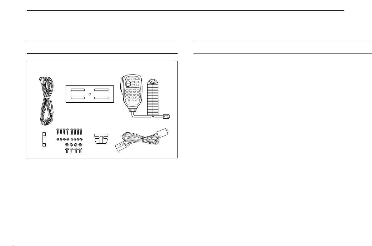
qDC power cable (3 m) ………………………………………1
wMobile mounting bracket …………………………………1
eMicrophone (HM-133)* ……………………………………1
rFuse (20 A) …………………………………………………1
tMounting screws, nuts and washers …………………1 set
yMicrophone hanger …………………………………………1
uSeparation cable†(3.5 m; 11.5 ft) …………………………1
*HM-118N
HAND MICROPHONE
or HM-118TN/TAN
DTMF MICROPHONE
supplied versions are also available.
†Aferrite core is adapted for the USA version.
q
w
e
r
tyu
FOREWORD ........................................................................................... i
IMPORTANT ............................................................................................ i
EXPLICIT DEFINITIONS ......................................................................... i
PRECAUTION ........................................................................................ ii
SUPPLIED ACCESSORIES .................................................................. iii
TABLE OF CONTENTS ......................................................................... iii
QUICK REFERENCE GUIDE ............................................................. I–X
■Installation ....................................................................................... I
■Your first contact .......................................................................... VII
■Repeater operation ....................................................................... IX
■Programming memory channels..................................................... X
1PANEL DESCRIPTION ............................................................... 1–10
■Front panel— controller ................................................................. 1
■Function display ............................................................................. 3
■Rear panel ..................................................................................... 5
■Microphone (HM-133) .................................................................... 7
■Microphone keypad ........................................................................ 8
■Optional microphones (HM-118N/TN/TAN)................................... 10
2SETTING A FREQUENCY ........................................................ 11–14
■Preparation ................................................................................... 11
■Using the tuning dial .................................................................... 12
■Using the [Y]/[Z] keys ................................................................. 12
■Using the keypad ......................................................................... 12
■Tuning step selection ................................................................... 13
■Lock functions .............................................................................. 14
3BASIC OPERATION ................................................................. 15–18
■Receiving ..................................................................................... 15
■Monitor function ........................................................................... 15
■Squelch attenuator ....................................................................... 16
■Transmitting ................................................................................. 17
■Selecting output power ................................................................ 17

iv
1
2
3
4
5
6
7
8
9
10
11
12
13
14
■One-touch PTT function ............................................................... 18
■Audio mute function ..................................................................... 18
4REPEATER OPERATION ......................................................... 19–25
■General ........................................................................................ 19
■Accessing a repeater ................................................................... 20
■Subaudible tones ......................................................................... 22
■Offset frequency .......................................................................... 24
■Auto repeater (USA version only) ................................................ 25
5 MEMORY OPERATION ............................................................ 26–37
■General description ...................................................................... 26
■Memory channel selection ........................................................... 26
■Programming a memory channel ................................................. 27
■Copying memory contents ........................................................... 29
■Programming channel names ..................................................... 31
■Memory clearing .......................................................................... 34
■Memory bank selection ................................................................ 35
■Memory bank setting .................................................................... 36
■Transferring bank contents .......................................................... 37
6CALL CHANNEL OPERATION ................................................ 38–39
■Call channel selection .................................................................. 38
■Call channel transferring .............................................................. 38
■Programming a call channel ........................................................ 39
7SCAN OPERATION .................................................................. 40–45
■Scan types ................................................................................... 40
■Scan start/stop ............................................................................. 41
■Scan edges programming ............................................................ 42
■Skip channel setting ..................................................................... 44
■Scan resume condition ................................................................ 45
8 PRIORITY WATCH .................................................................... 46–47
■Priority watch types ...................................................................... 46
■Priority watch operation ............................................................... 47
9DTMF MEMORY ENCODER ..................................................... 48–51
■Programming a DTMF code ......................................................... 48
■Transmitting a DTMF code .......................................................... 50
■DTMF speed ................................................................................ 51
10 POCKET BEEP AND TONE SQUELCH ................................... 52–55
■Pocket beep operation ................................................................. 52
■Tone/DTCS squelch operation ..................................................... 54
■Tone scan ..................................................................................... 55
11 OTHER FUNCTIONS ................................................................ 56–74
■Set mode ...................................................................................... 56
■Initial set mode ............................................................................. 61
■AM/FM narrow mode ................................................................... 65
■Weather channel operation (USA version only) ........................... 66
■Microphone keys .......................................................................... 67
■Partial reset .................................................................................. 68
■All reset ........................................................................................ 68
■Data cloning ................................................................................. 69
■Packet operation .......................................................................... 71
12 DIGITAL MODE OPERATION ................................................... 75–87
■Digital mode operation ................................................................. 75
■Call sign programming ................................................................. 75
■Digital voice mode operation ........................................................ 77
■When receiving a Digital call ........................................................ 79
■Break-in communication .............................................................. 79
■EMR communication .................................................................... 80
■Digital code/Call sign squelch operation ...................................... 80
■Slow data communication ............................................................ 81
■Other setting items ....................................................................... 82
■GPS operation ............................................................................. 87
I
QUICK REFERENCE GUIDE
■Installation
DInstallation methods
•Single body installation
•The supplied mounting bracket (or optional MB-17A) can be
used for the main unit installation.
•Remote installation
•The supplied OPC-600/R
SEPARATION CABLE
can be used for
remote installation.
•Optional OPC-601/R
SEPARATION CABLE
(7 m; 23 ft) is avail-
able for extend installation.
•Optional MB-58
REMOTE CONTROLLER BRACKET
and MB-65
MOUNTING BASE
are available for increasing front panel
mounting possibilities.
•Optional OPC-440
MICROPHONE CABLE
(5.0 m; 16.4 ft) and
OPC-647 (2.5 m; 8.2 ft) are available to extend the micro-
phone cable.
•Optional OPC-441
SPEAKER CABLE
(5.0 m; 16.4 ft) is avail-
able to extend the speaker cable.
Main unit
Front panel
Transceiver
II
QUICK REFERENCE GUIDE
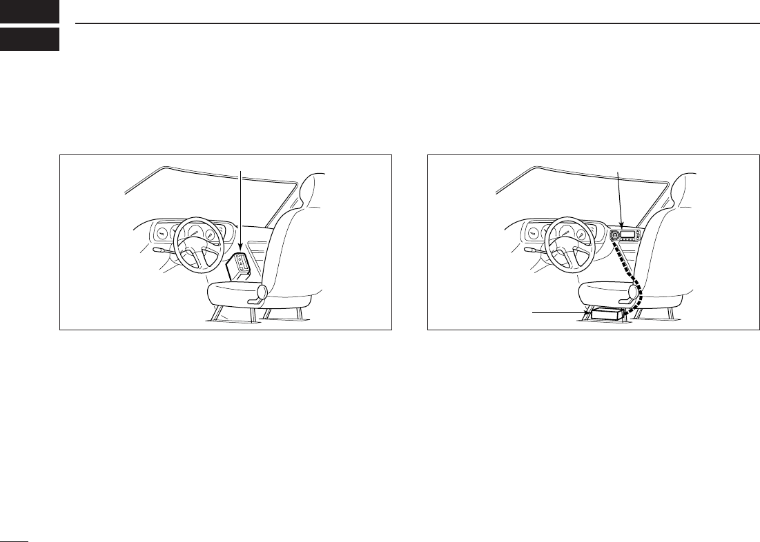
DLocation
Select a location which can support the weight of the trans-
ceiver and does not interfere with driving. We recommend the
locations shown in the diagram below.
NEVER place the transceiver or remote controller where nor-
mal operation of the vehicle may be hindered or where it
could cause bodily injury.
NEVER place the transceiver or remote controller where air
bag deployment may be obstructed.
DO NOT place the transceiver or remote controller where hot
or cold air blows directly onto it.
AVOID placing the transceiver or remote controller in direct
sunlight.
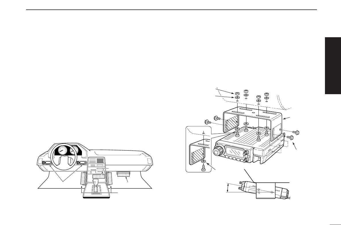
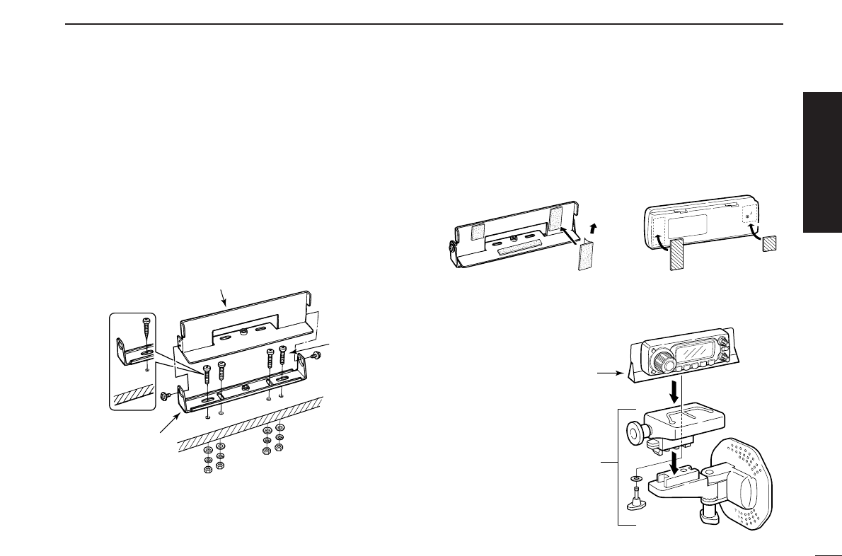
DUsing the mounting bracket
qDrill 4 holes where the mounting bracket is to be installed.
•Approx. 5.5–6 mm (1⁄4″) when using nuts; approx. 2–3 mm (1⁄8″)
when using self-tapping screws.
wInsert the supplied screws, nuts and washers through the
mounting bracket and tighten.
eAdjust the angle for your suitable position.
25˚
Nut
Spring washer
When using
self-tapping
screws
Flat washer
Mounting nut
Mounting
bracket
Controller
Main unit
Main unit
Main unit
Quick reference guide
III
QUICK REFERENCE GUIDE
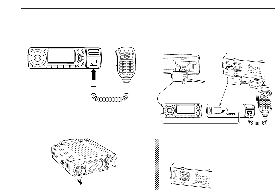
DMicrophone connection
Connect the supplied microphone as illustrated below.
DSeparation cable connection
Using the supplied separation cable (3.5 m; 11.5 ft) or the op-
tional separation cable (7 m; 23 ft) the controller can be sep-
arated from the main unit, doubling as a remote controller.
qDetach the controller as below.
wConnect a separation cable between the controller and
main unit using the supplied screws as illustrated below.
Aferrite core is adapted for the USA version.
CAUTION!
NEVER short the terminals of the separation connector.
The 13.8 V power line is available in the connector, so the
transceiver may damage when short circuited.
NEVER short the terminals
• Controller’s rear panel • Main unit
OPC-600/R or OPC-601/R
q
w
e
Release latch
IV
QUICK REFERENCE GUIDE
DOptional MB-58 installation
The optional MB-58
REMOTE CONTROLLER BRACKET
is avail-
able for separate installation.
qDrill 2 or 4 holes where the bracket is to be installed.
•Approx. 4 mm (1⁄8″) when using nuts; approx. 1–2 mm (1⁄16″)
when using self-tapping screws.
wInsert the supplied screws, bolts and washers through the
mounting base and tighten.
eAdjust the angle for the clearest view of the function dis-
play and tighten 2 screws when the mounting base is used.
rAttach the supplied Velcro pads (large) to the remote con-
troller and bracket.
tAttach the supplied Velcro pads (small) or rubber pad to
the bracket as shown below; then attach the remote con-
troller.
•When using the optional MB-65
MB-58
MB-65
Adjust the viewing
angle for maximum
visibility of the
function display.
MB-58 ID-800H remote controller
Bracket
When using self-
tapping screws.
Mounting
base
Mounting
bolt
Quick reference guide
V
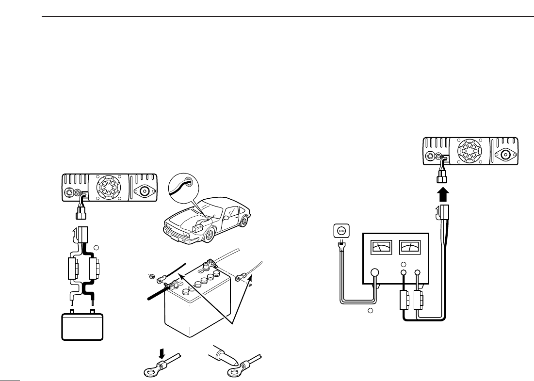
DBattery connection
☞RWARNING NEVER remove the fuse holders from the
DC power cable.
☞NEVER connect the transceiver directly to a 24 V battery.
☞DO NOT use the cigarette lighter socket for power con-
nections. (See p. 5 for details)
Attach a rubber grommet when passing the DC power cable
through a metal plate to prevent a short circuit.
•CONNECTING TO A DC POWER SOURCE
DDC power supply connection
Use a 13.8 V DC power supply with at least 15 A capacity.
Make sure the ground terminal of the DC power supply is
grounded.
•CONNECTING TO A DC POWER SUPPLY
See p. 76 for fuse replacement.
DC power
supply 13.8 V
to an
AC
outlet
Fuses
20 A
black
red⊕
−
⊕
−
ID-800H
ID-800H
Fuses
20 A
black
red⊕−
12 V
Grommet
NOTE:
Use terminals for the
cable connections.
WARNING!
NEVER
remove the
fuse holders.
Crimp Solder
12 V
battery Supplied
DC power cable
+ red
_ black
QUICK REFERENCE GUIDE
VI
QUICK REFERENCE GUIDE
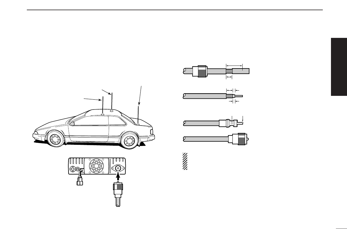
DAntenna installation
•Antenna location
To obtain maximum performance from the transceiver, select
a high-quality antenna and mount it in a good location. A non-
radial antenna should be used when using a magnetic mount.
•Antenna connector
The antenna uses a PL-259 connector.
•PL-259 CONNECTOR
qSlide the coupling ring
down. Strip the cable
jacket and soft solder.
wStrip the cable as shown
at left. Soft solder the cen-
ter conductor.
eSlide the connector body
on and solder it.
rScrew the coupling ring
onto the connector body.
(10 mm ≈3⁄8 in)
NOTE: There are many publications covering proper an-
tennas and their installation. Check with your local dealer
for more information and recommendations.
30 mm
10 mm (soft solder)
10 mm
1–2 mm
solder solder
Soft
solder
Coupling ring
To antenna
Roof-mount antenna
(Drill a hole or use a magnetic mount.)
Gutter-mount antenna
Trunk-mount
antenna
Quick reference guide
VII
QUICK REFERENCE GUIDE
■Your first contact
Now that you have your ID-800H installed in your car or
shack, you are probably excited to get on the air. We would
like to take you through a few basic operation steps to make
your first “On The Air” an enjoyable experience.
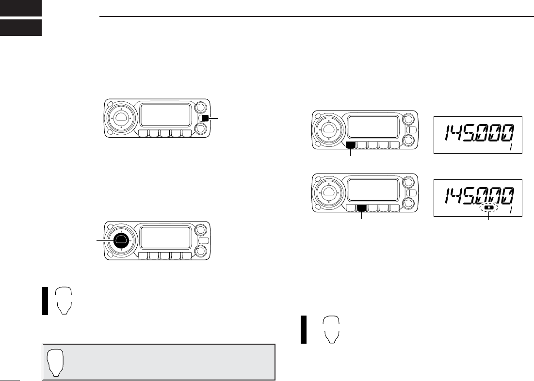
1. Turning ON the transceiver
Before powering up your ID-800H, you may want to make
sure the audio volume and squelch level controls are set in
9–10 o’clock positions.
Although you have purchased a brand new transceiver, some
settings may be changed from the factory defaults because
of the QC process. Resetting the CPU is necessary to start
from factory default.
➥While pushing both [SET•LOCK] and [S.MW•MW], push
[PWR] for 1 sec. to reset the CPU.
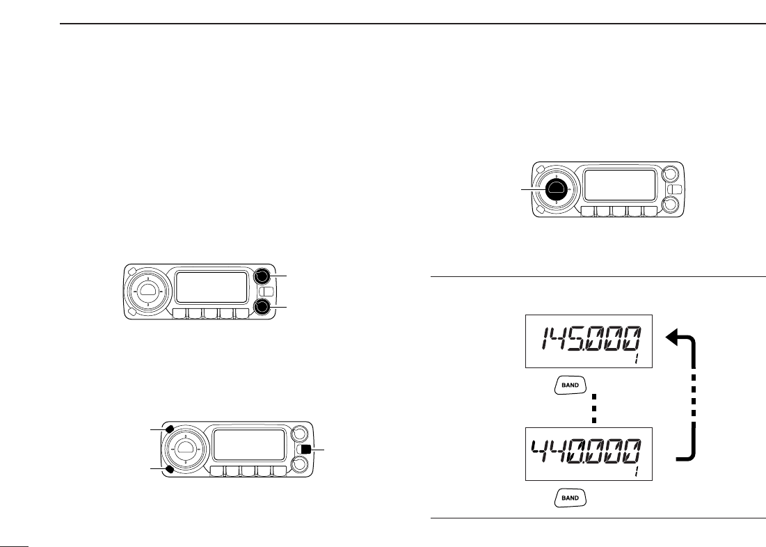
2. Selecting the operating frequency band
The ID-800H has 2 m and 70 cm transmittable bands.
➥Push [BAND] to select the desired frequency band.
Using the HM-133
You can select the desired frequency band from the HM-133.
Push
Push
Push [BAND] to select the desired frequency band.
[BAND]
[PWR]
While pushing [SET•LOCK] and [S.MW•MW], turn power ON.
[SET•LOCK]
[S.MW•MW]
[VOL]
Set [VOL] and [SQL] controls to 9–10 o’clock positions.
[SQL]
VIII
QUICK REFERENCE GUIDE
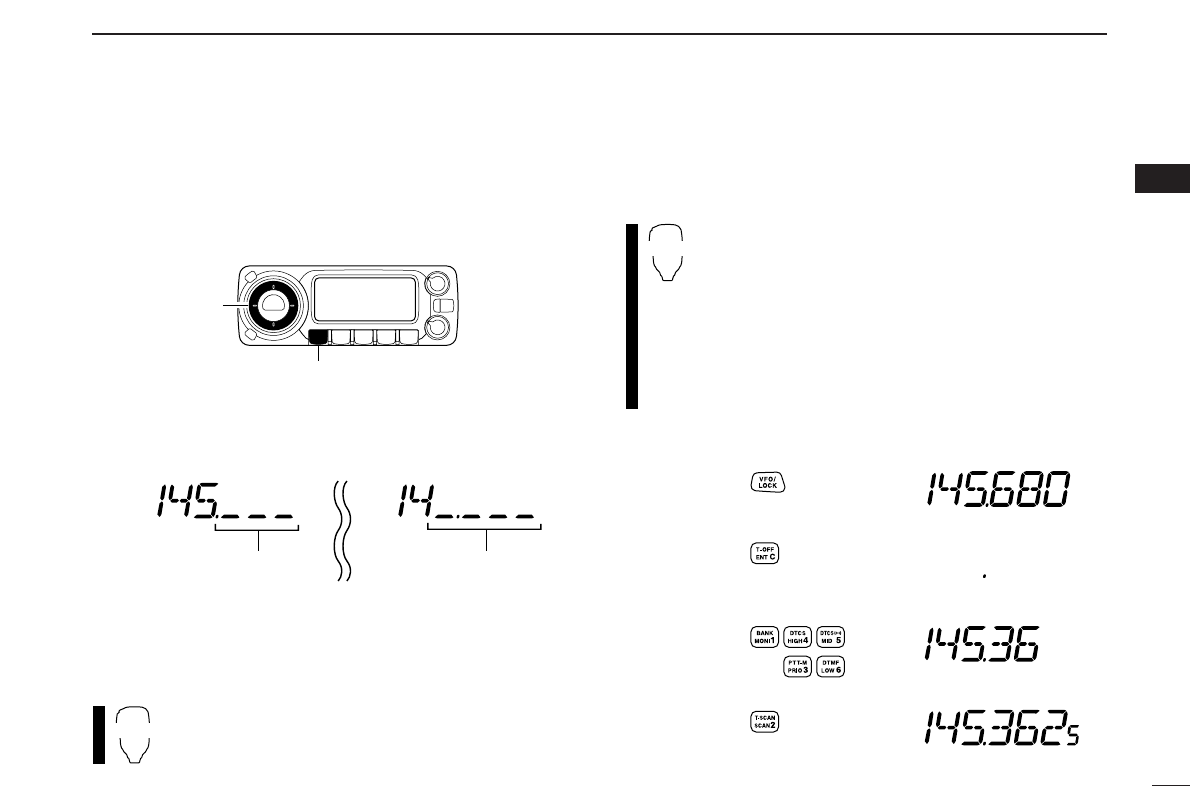
3. Tune the frequency
The tuning dial will allow you to dial in the frequency you want
to operate. Pages 12 and 13 will instruct you on how to set
the tuning speed.
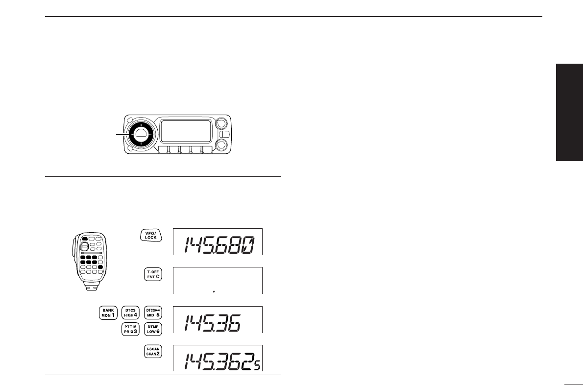
Using the HM-133
You can directly enter the frequency with the HM-133 keypad
for the main band.
[EXAMPLE]: Setting frequency to 145.3625 MHz.
Push
Push
Push
Push
Rotate [DIAL] to tune the frequency.
[DIAL]
Quick reference guide
IX
QUICK REFERENCE GUIDE
■Repeater operation
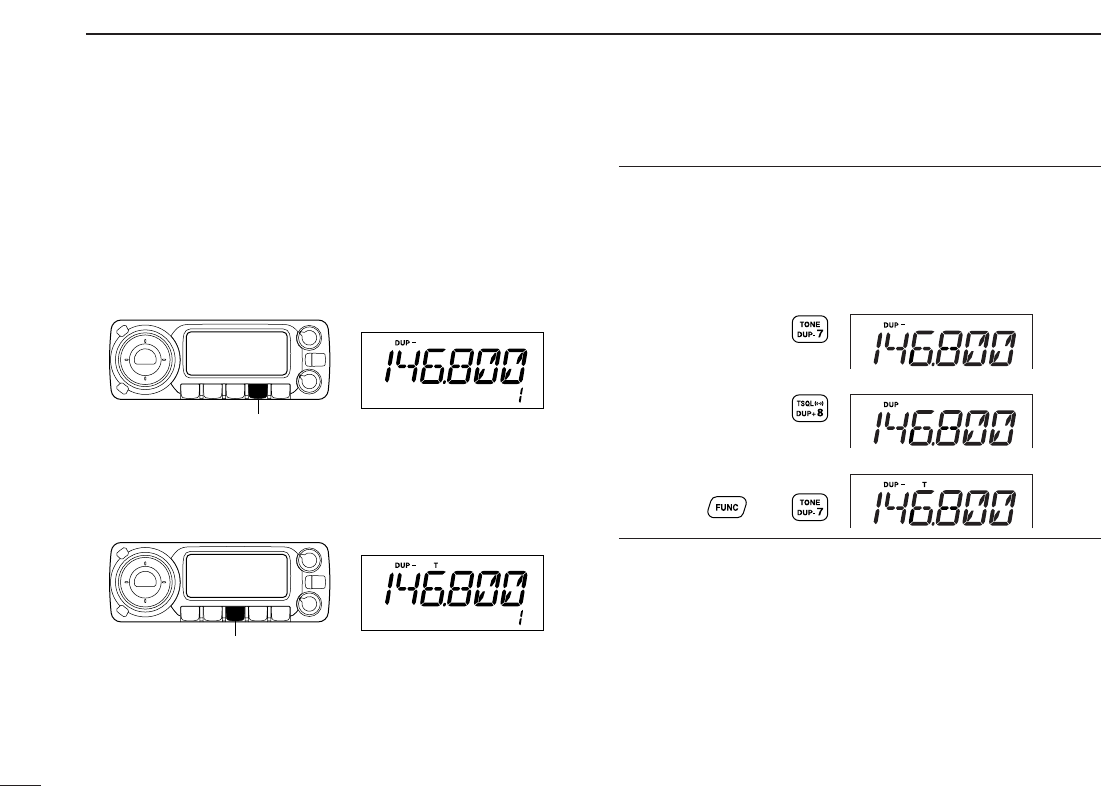
1. Setting duplex
Push [BAND] to select the frequency band.
Push [LOW•DUP] for 1 sec. once or twice to select minus du-
plex or plus duplex.
•The USA version has an auto repeater function, therefore, setting
duplex is not required.
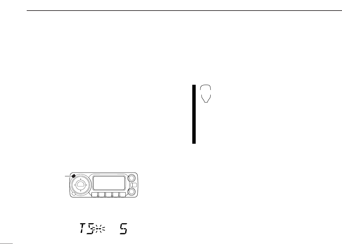
2. Repeater tone
Push [TONE•T-SCAN] several times until “T” appears, if the
repeater requires a subaudible tone to be accessed.
Using the HM-133
Plus or minus duplex selection and the repeater tone setting
can be made easily via HM-133.
Push [
DUP
–7(TONE)] for minus duplex; [
DUP
+8(TSQLS)]
for plus duplex selection, push [FUNC] then [
DUP
–7(TONE)]
to turn the repeater tone ON.
Push
Push , then
Push
[TONE•T-SCAN]
[LOW•DUP]
X
QUICK REFERENCE GUIDE
Quick reference guide
■Programming memory channels
The ID-800H has a total of 512 memory channels (including
10 scan edges and 2 call channels) for storing often used op-
erating frequency, repeater settings, etc.
1. Setting a frequency
In VFO mode, set the desired operating frequency with re-
peater, tone and tuning steps, etc.
➥Push [V/MHz•SCAN] to select VFO.
➥
Rotate [DIAL] to set the desired frequency.
•Set other data, such as repeater tone, duplex information, tuning
step), if desired.
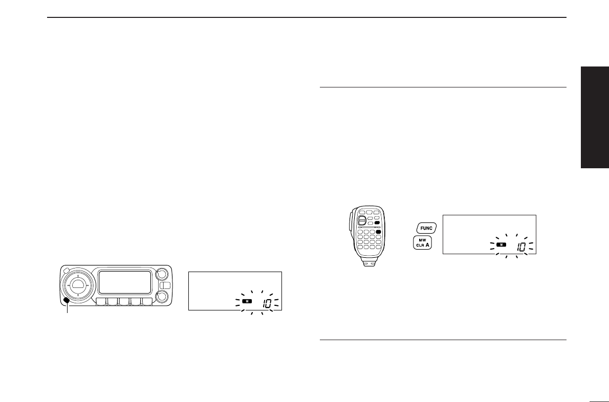
2. Selecting a memory channel
Push [S.MW•MW], then rotate [DIAL] to select the desired
memory channel.
•“!” indicator and memory channel number blink.
3. Writing a memory channel
Push and hold [S.MW•MW] for 1 sec. to program.
•3 beeps sound
•Return to VFO mode automatically after the program.
•Memory channel number automatically increases when continuing
to push [S.MW•MW] after programming.
Using the HM-133
qIn VFO mode, set the desired operating frequency, includ-
ing offset direction, tone settings, etc.
➥Push [VFO/LOCK] to select VFO.
➥Push [
ENT
C(T-OFF)] first, then enter the desired oper-
ating frequency via the keypad.
•Set other data, such as repeater tone, duplex information,
tuning step, if necessary.
wPush [FUNC] then [
CLR
A(MW)].
•“!” indicator and memory channel number blink.
ePush [Y]/[Z] to select the desired memory channel.
rPush [FUNC] then push [
CLR
A(MW)] for 1 sec. to pro-
gram.
•3 beeps sound
•Memory channel number automatically increases when continu-
ing to push [
CLR
A(MW)] after programming.
Push ,
then
[S.MW•MW]
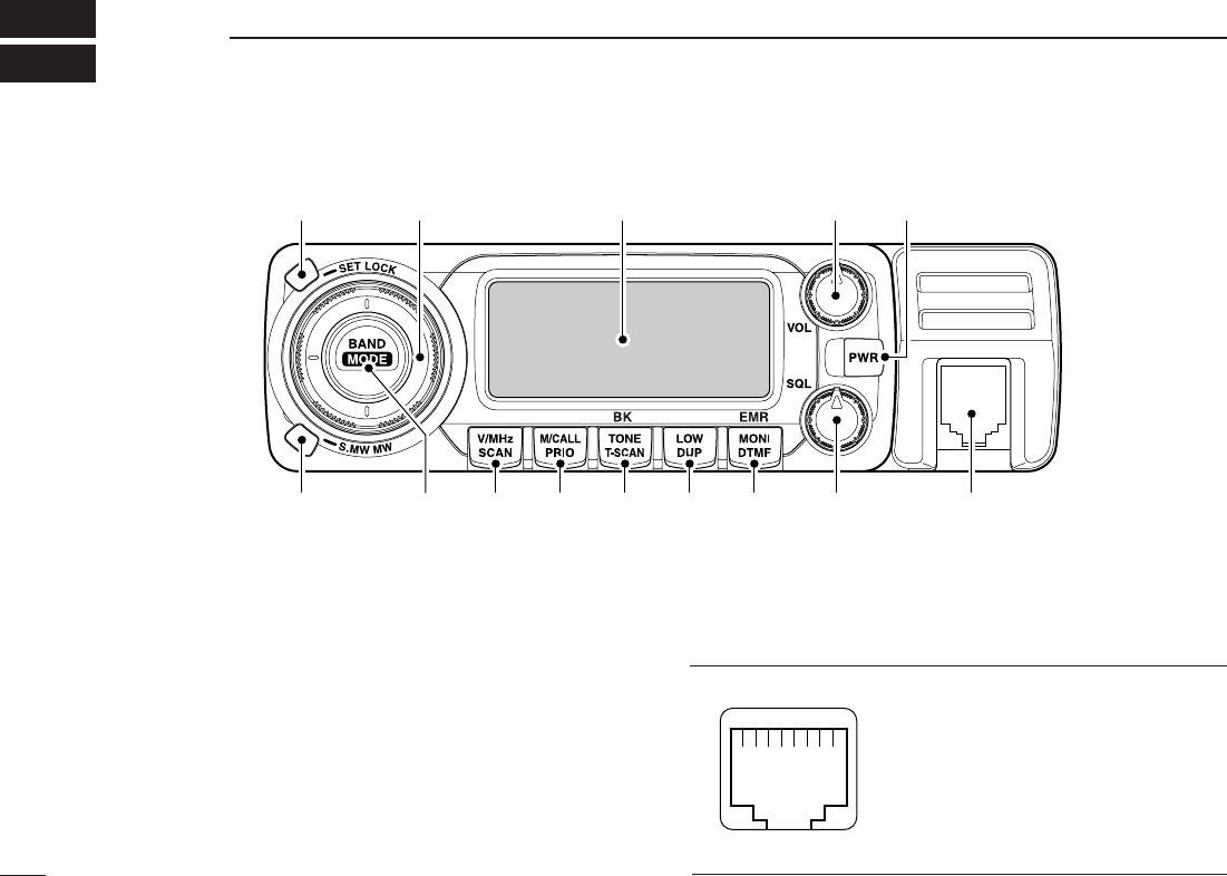
■Front panel— controller
qSET•LOCK SWITCH [SET•LOCK]
➥Enters set mode when pushed. (p. 56)
➥Switches the lock function ON and OFF when pushed
for 1 sec. (p. 14)
wTUNING DIAL [DIAL]
Selects the operating frequency (p. 12), memory channel
(p. 26), the setting of the set mode item and the scanning
direction (p. 41).
eVOLUME CONTROL [VOL] (p. 15)
Adjusts the audio level.
rPOWER SWITCH [PWR]
Turns power ON and OFF when pushed for 1 sec.
tMICROPHONE CONNECTOR
Connects the supplied or an optional microphone.
q+8 V DC output (Max. 10 mA)
wChannel up/down
e8V control IN
rPTT
tGND (microphone ground)
yMIC (microphone input)
uGND
iData IN
qi
q w Function display (p. 3) e r
t
yuio!0!1!2!3
1
PANEL DESCRIPTION
1
2
1
PANEL DESCRIPTION
1
ySQUELCH CONTROL [SQL]
Varies the squelch level. (p. 15)
•The RF attenuator activates and increases the attenuation when
rotated clockwise to the center position and further. (p. 16)
uMONITOR•DTMF SWITCH [MONI•DTMF]
➥Push to switch the monitor function ON and OFF. (p. 15)
➥Turns DTMF memory encoder ON and OFF when
pushed for 1 sec. (p. 48)
iOUTPUT POWER•DUPLEX SWITCH [LOW•DUP]
➥Each push changes the output power selection. (p. 17)
➥Push for 1 sec. to select DUP–, DUP+ and simplex op-
eration. (p. 20)
oTONE•TONE SCAN SWITCH [TONE•T-SCAN]
➥Each push selects a tone function. (pgs. 20, 52)
•Subaudible tone encoder, pocket beep (CTCSS), tone
squelch, pocket beep (DTCS), DTCS squelch or tone func-
tion OFF can be selected.
➥Push for 1 sec. to start the tone scan. (p. 55)
!0MEMORY/CALL•PRIORITY SWITCH [M/CALL•PRIO]
➥Push to select and toggle memory, call and weather
channel* modes. (pgs. 11, 26, 38, 66)
*Weather channels are available for USA version only.
➥Starts priority watch when pushed for 1 sec. (p. 47)
!1VFO/MHz TUNING•SCAN SWITCH [V/MHz•SCAN]
➥Selects and toggles VFO mode and 1 MHz (or 10 MHz
for some versions) tuning when pushed. (p. 11)
➥Starts scan when pushed for 1 sec. (p. 41)
•Cancels a scan when pushed during scan.
!2BAND SWITCH [BAND/MODE]
➥While VFO operation, push to select the operating fre-
quency band. (p. 11)
➥While call channel operation, push to select the call
channel 1or 2 during call channel operation. (p. 38)
➥While memory channel operation, push to select mem-
ory bank condition. (p. 35)
➥Push for 1 sec. to select the operating mode. (p. 65)
!3MEMORY WRITE SWITCH [S.MW•MW] (pgs. 27, 39, 42)
➥Selects a memory channel for programming when
pushed.
➥Programs the selected memory channel when pushed
for 1 sec.
!4CONTROLLER RELEASE LATCH
While pushing this latch, slide the controller to the left to
remove it.
!4
3
1PANEL DESCRIPTION
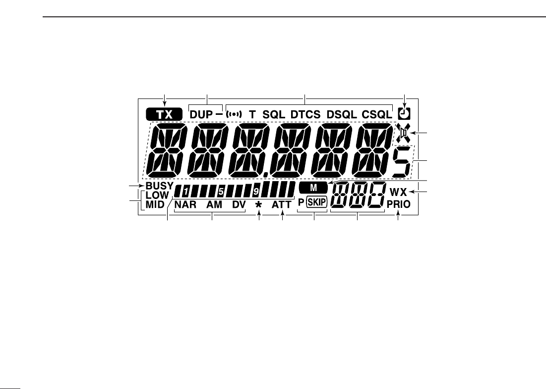
■Function display
qTRANSMIT INDICATOR
➥Appears while transmitting. (p. 17)
➥Blinks while transmitting with the one-touch PTT func-
tion. (p. 18)
wDUPLEX INDICATORS (p. 20)
“DUP” appears when plus duplex, “DUP –” appears when
minus duplex (repeater) operation is selected.
eTONE/DIGITAL SQUELCH INDICATORS
❍While in the analog (FM/AM) mode operation
➥“T” appears while the subaudible tone encoder is in
use. (p. 20)
➥“T SQL” appears while the tone squelch function is in
use. (p. 52)
➥“DTCS” appears while the DTCS squelch function is
in use. (p. 52)
➥“S” appears with the “T SQL” or “DTCS” indicator
while the pocket beep function (with CTCSS or DTCS)
is in use. (p. 52)
❍While in the digital mode operation
➥“DSQL” appears while the call sigh squelch function
is in use. (p. 52)
➥“CSQL” appears while the digital code squelch func-
tion is in use. (p. 52)
➥“S” appears with the “DSQL” or “CSQL” indicator
while the pocket beep function (with DSQL or CSQL) is
in use. (p. 52)
q
t
r
i
we
u
y
o!2!3 !0
!6
!7
!4 !1!5

4
1
PANEL DESCRIPTION
1
rAUTO POWER-OFF INDICATOR (p. 62)
Appears while the auto power OFF function is in use.
tAUDIO MUTE INDICATOR (P. 18)
Appears when the audio mute function is activated.
•The mute can only be switched ON and OFF from the HM-133
only.
yFREQUENCY READOUT
Shows the operating frequency, channel names, set mode
contents, etc.
•Frequency decimal point blinks while scanning. (p. 41)
•“d” appears in place of the 1st digit while the DTMF memory
function is in use. (p. 48)
uMEMORY INDICATOR (pgs. 11, 26)
Appears when memory mode is selected.
iWEATHER ALERT INDICATOR (p. 66)
Appears when the weather alert function is activated.
•The either alert function is available with the USA version only.
1oPRIORITY INDICATOR (p. 47)
Appears while the priority watch is activated; blinks while
the watch is paused.
!0MEMORY CHANNEL NUMBER INDICATORS
➥Shows the selected memory channel number. (p. 26)
➥Shows the selected bank initial. (p. 35)
➥“C” appears when the call channel is selected. (p. 38)
➥“L” appears when the lock function is activated. (p. 14)
!1SKIP INDICATORS (p. 44)
➥“~”appears when the displayed memory channel is
specified as a skip channel.
➥“P ~” appears when the displayed frequency is spec-
ified as a program skip frequency.
!2SQUELCH ATTENUATOR INDICATOR (p. 16)
Appears when the squelch attenuator function is activated.
•The attenuator can be switched OFF in initial set mode. (p. 63)
!3DIGITAL MESSAGE INDICATOR (p. 61)
Appears when a digital message is received.
!4MODE INDICATORS
➥No indication appears while in the FM mode operation.
(p. 65)
➥“AM” appears while in the AM mode operation. (p. 65)
➥“NAR” appears while in the FM/AM narrow mode oper-
ation. (p. 65)
➥“DV” appears while in the digital mode operation. (p. ??)
•Blinking all indication indicates the FM mode selection while
setting.
!5S/RF INDICATORS
➥Shows the relative signal strength while receiving sig-
nals. (p. 15)
➥Shows the output power level while transmitting. (p. 17)
!6OUTPUT POWER INDICATORS
“LOW” appears when low output power; “MID” appears
when middle output power is selected.
No indicator appears when high output power is selected.
!7BUSY INDICATOR
➥Appears when a signal is being received or the squelch
is open. (p. 15)
➥Blinks while the monitor function is activated. (p. 15)
5
1PANEL DESCRIPTION
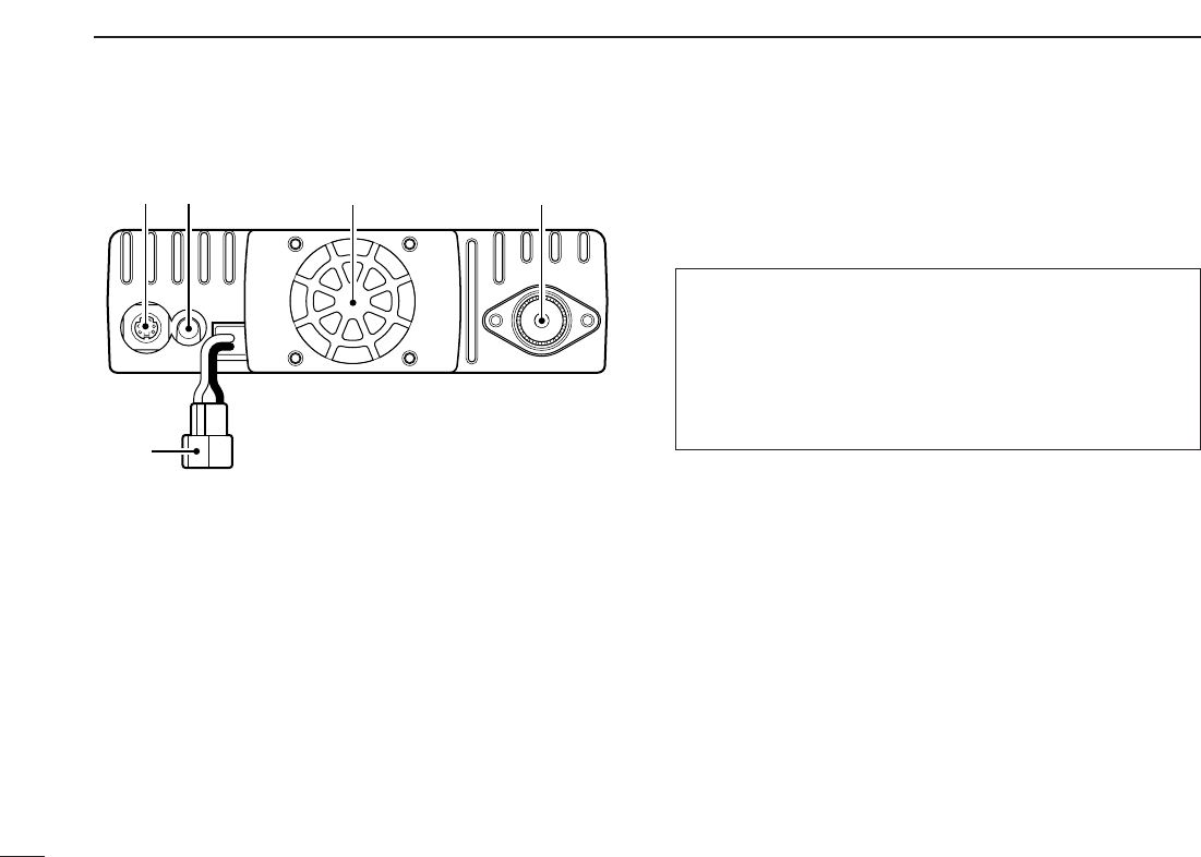
■Rear Panel
qDATA SOCKET [DATA]
Connects a TNC (Terminal Node Controller), etc. for data
communications.
•See p. 6 for connection information.
wEXTERNAL SPEAKER JACK [SP]
Connects an 8 Ωspeaker.
•Audio output power is more than 2.0 W.
eCOOLING FAN
Rotates while transmitting.
Also rotates while receiving depending on the setting in ini-
tial set mode. (p. 63)
rANTENNA CONNECTOR [ANT]
Connects a 50 Ωantenna with a PL-259 connector and a
50 Ωcoaxial cable.
tPOWER RECEPTACLE [DC13.8V]
Accepts 13.8 V DC ±15% with the supplied DC power
cable.
☞NOTE: DO NOT use a cigarette lighter socket as a
power source when operating in a vehicle. The plug
may cause voltage drops and ignition noise may be su-
perimposed onto transmit or receive audio.
ANTENNA INFORMATION
For radio communications, the antenna is of critical impor-
tance, to maximize your output power and receiver sensi-
tivity. The transceiver accepts a 50 Ωantenna and less
than 1:1.5 of Voltage Standing Wave Ratio (VSWR). High
SWR values not only may damage the transceiver but also
lead to TVI or BCI problems.
qwre
t

6
1
PANEL DESCRIPTION
1
DDATA JACK PIN ASSIGNMENT
qDATA IN
Input terminal for data transmit. See p. 63 for details on
how to toggle data speed between 1200 (AFSK) and
9600 bps (G3RUH, GMSK).
wGND
Common ground for DATA IN, DATA OUT and AF OUT.
ePTT P
PTT terminal for packet operation only. Connect ground to
transmit data.
rDATA OUT
Data out terminal for 9600 bps operation only.
tAF OUT
Data out terminal for 1200 bps operation only.
yPSQL
Becomes high (+5 V) when the transceiver receives a sig-
nal which opens the squelch.
•To avoid unnecessary TNC transmission, connect squelch to the
TNC to inhibit transmission when receiving signals.
•Keep audio output at a normal level, otherwise a “P SQL” signal
will not be output.
Front panel view
w
y
r
q
e
t
7
1PANEL DESCRIPTION
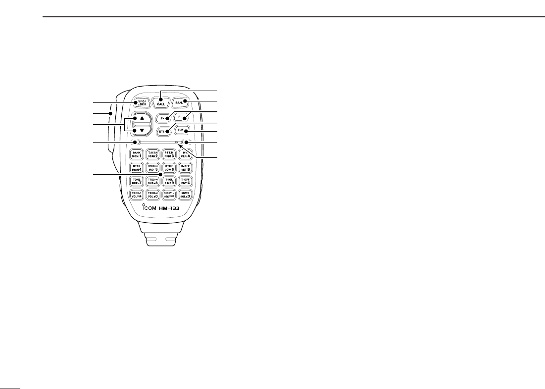
■Microphone (HM-133*)
qVFO/LOCK SWITCH [VFO/LOCK]
➥Push to select VFO mode. (p. 11)
➥Push for 1 sec. to switch the lock function ON and OFF.
(p. 14)
wPTT SWITCH
➥Push and hold to transmit; release to receive.
➥Switches between transmitting and receiving while the
one-touch PTT function is in use. (p. 18)
eUP/DOWN SWITCHES [Y]/[Z]
➥Push either switch to change operating frequency,
memory channel, set mode setting, etc.
(pgs. 12, 26, 56)
➥Push either switch for 1 sec. to start scanning. (p. 41)
rACTIVITY INDICATOR
➥Lights red while any key, except [FUNC] and [DTMF-S],
is pushed, or while transmitting.
➥Lights green while the one-touch PTT function is in use.
tKEYPAD (pgs. 8, 9)
yFUNCTION INDICATOR
➥Lights orange while [FUNC] is activated—indicates the
secondary function of switches can be accessed.
➥Lights green when [DTMF-S] is activated—DTMF sig-
nals can be transmitted with the keypad.
u2nd FUNCTION SWITCH [FUNC]
iDTMF SELECT SWITCH [DTMF-S] (p. 50)
oFUNCTION SWITCHES [F-1]/[F-2] (p. 67)
Program and recall your desired transceiver conditions.
!0BAND SWITCH [BAND]
➥Push to select the frequency band. (p. 11)
➥Push for 1 sec. to select the operating mode. (p. 65)
!1MEMORY/CALL SWITCH [MR/CALL]
➥Push to select memory mode. (p. 11)
➥Push for 1 sec. to select call channel. (p. 38)
Mic element
q
e
r
t
w
y
u
i
o
!0
!1
*
Adifferent microphone
may be supplied de-
pending on version.
8
1
PANEL DESCRIPTION
1
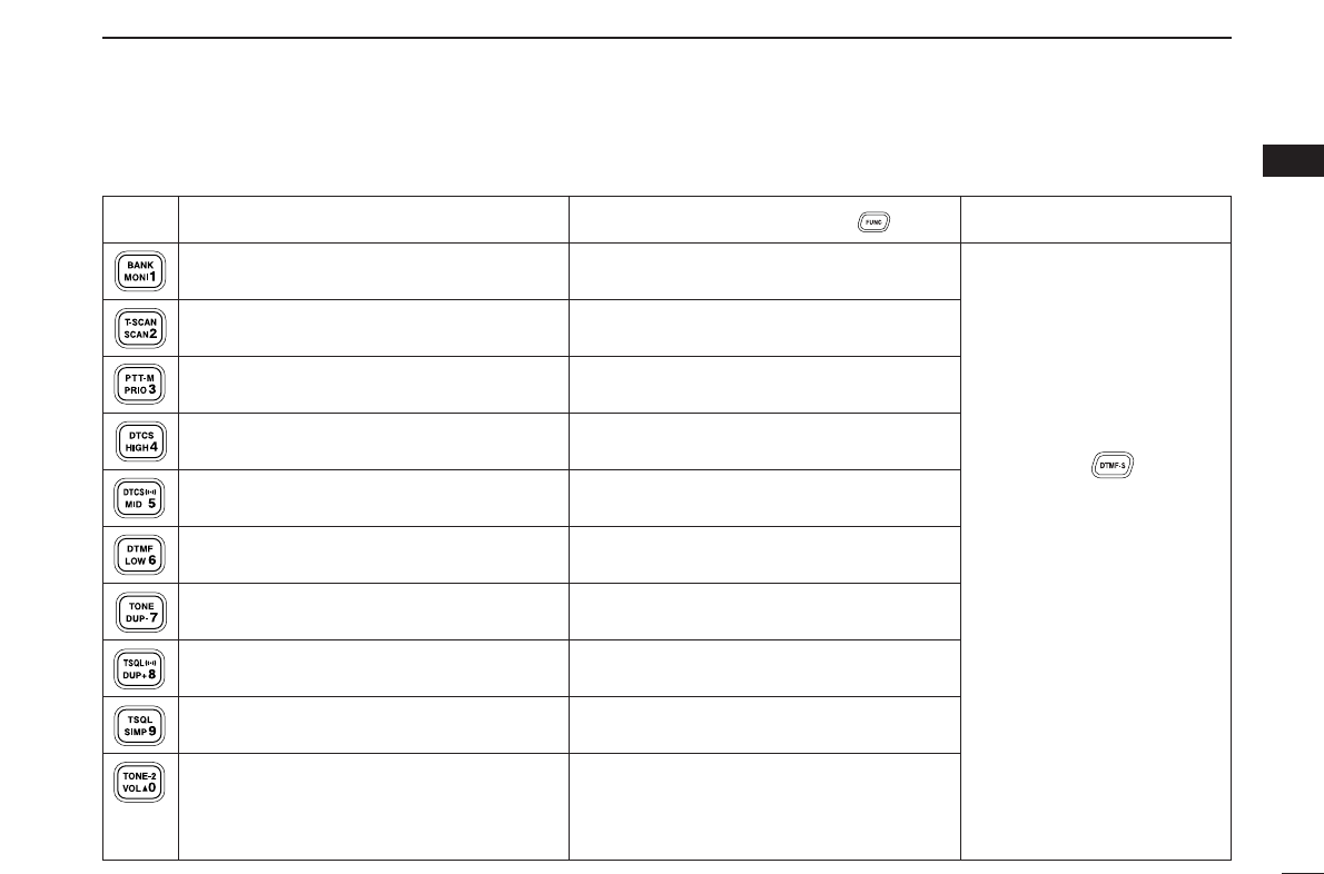
■Microphone keypad
KEY FUNCTION SECONDARY FUNCTION ( +key) OTHER FUNCTIONS
Switches between opening and closing the
squelch. (p. 15)
Starts and stops scanning. (p. 41)
Starts and stops priority watch. (p. 47)
Selects high output power. (p. 17)
Selects mid. output power. (p. 17)
Selects low output power (p. 17)
Selects minus duplex operation. (p. 21)
Selects plus duplex operation. (p. 21)
Selects simplex operation. (p. 21)
Increases audio output level. (p. 15)
In memory mode enters bank selecting
condition. (p. 35)
Starts and stops tone scanning. (p. 55)
Turns the one-touch PTT function ON and
OFF. (p. 18)
Turns the DTCS squelch ON. (p. 54)
Turns the DTCS pocket beep function ON.
(p. 53)
Turns the DTMF memory encoder function
ON. (p. 50)
Turns the subaudible tone encoder ON.
(p. 21)
Turns the CTCSS pocket beep function
ON. (p. 53)
Turns the tone squelch function ON.
(p. 54)
Sends a 1750 Hz tone signal while pushing
and holding. (p. 23)
After pushing :
Transmits the appropriate
DTMF code. (pgs. 23, 50)
When the DTMF memory en-
coder is activated, push [0] to
[9] to transmit the appropriate
DTMF memory contents.
(p. 50)
9
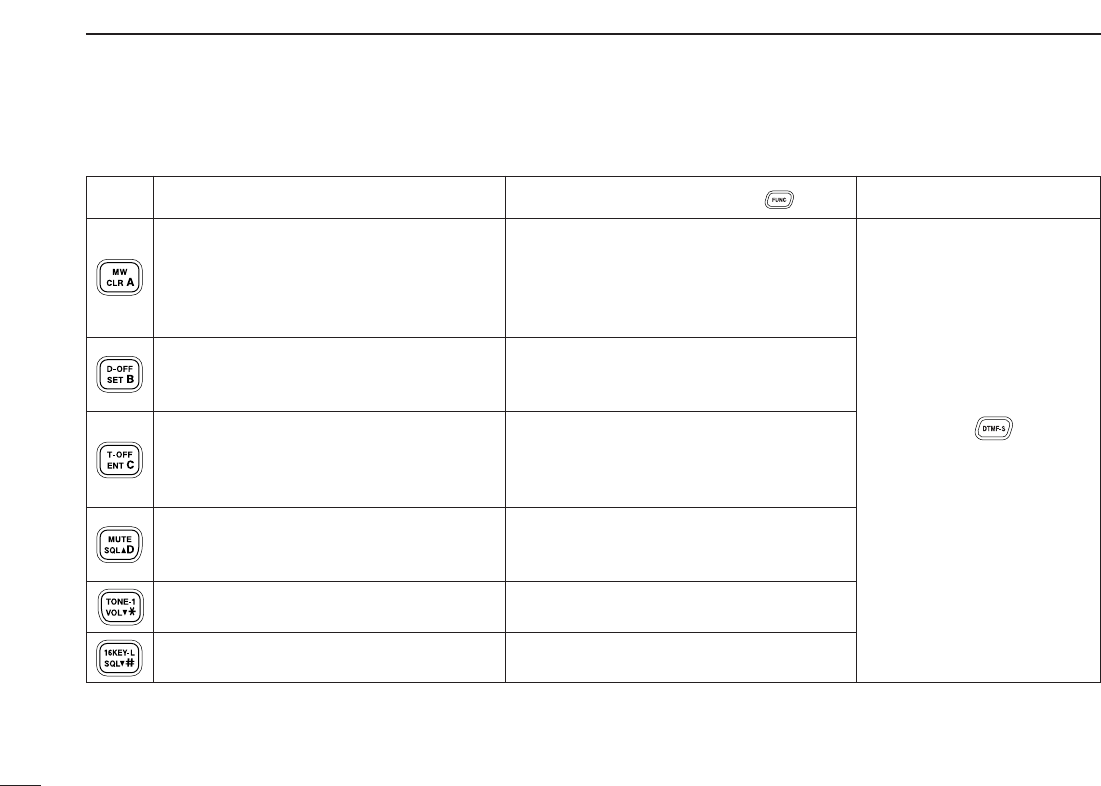
1PANEL DESCRIPTION
➥Cancels frequency entry. (p. 12)
➥Cancels the scan or priority watch.
(pgs. 41, 47)
➥Exit set mode. (p. 56)
➥Enters set mode (p. 56)
➥Advances the set mode selection order
after entering set mode. (p. 56)
➥Sets the keypad for numeral input.
(p. 12)
➥Reverses the set mode selection order
after entering set mode. (p. 56)
Adjusts the squelch level increments.
(p. 15)
Decreases audio output level. (p. 15)
Adjusts the squelch level decrement.
(p. 15)
➥Selects a memory channel for program-
ming. (p. 28)
➥Advances the memory channel number
when continuously pushed after pro-
gramming is completed. (p. 28)
DTMF memory encoder function OFF.
(p. 50)
Turns the subaudible tone encoder, pocket
beep or CTCSS/DTCS tone squelch OFF.
(pgs. 21, 53)
Mutes the audio. (p. 18)
•Mute function is released when any oper-
ation is performed.
Sends a 1750 Hz tone signal for 0.5 sec.
(p. 23)
Locks the digit keys on the keypad (includ-
ing the A to D, # and Mkeys). (p. 14)
After pushing :
Transmits the appropriate
DTMF code. (pgs. 23, 50)
KEY FUNCTION SECONDARY FUNCTION ( +key) OTHER FUNCTIONS
10
1
PANEL DESCRIPTION
1
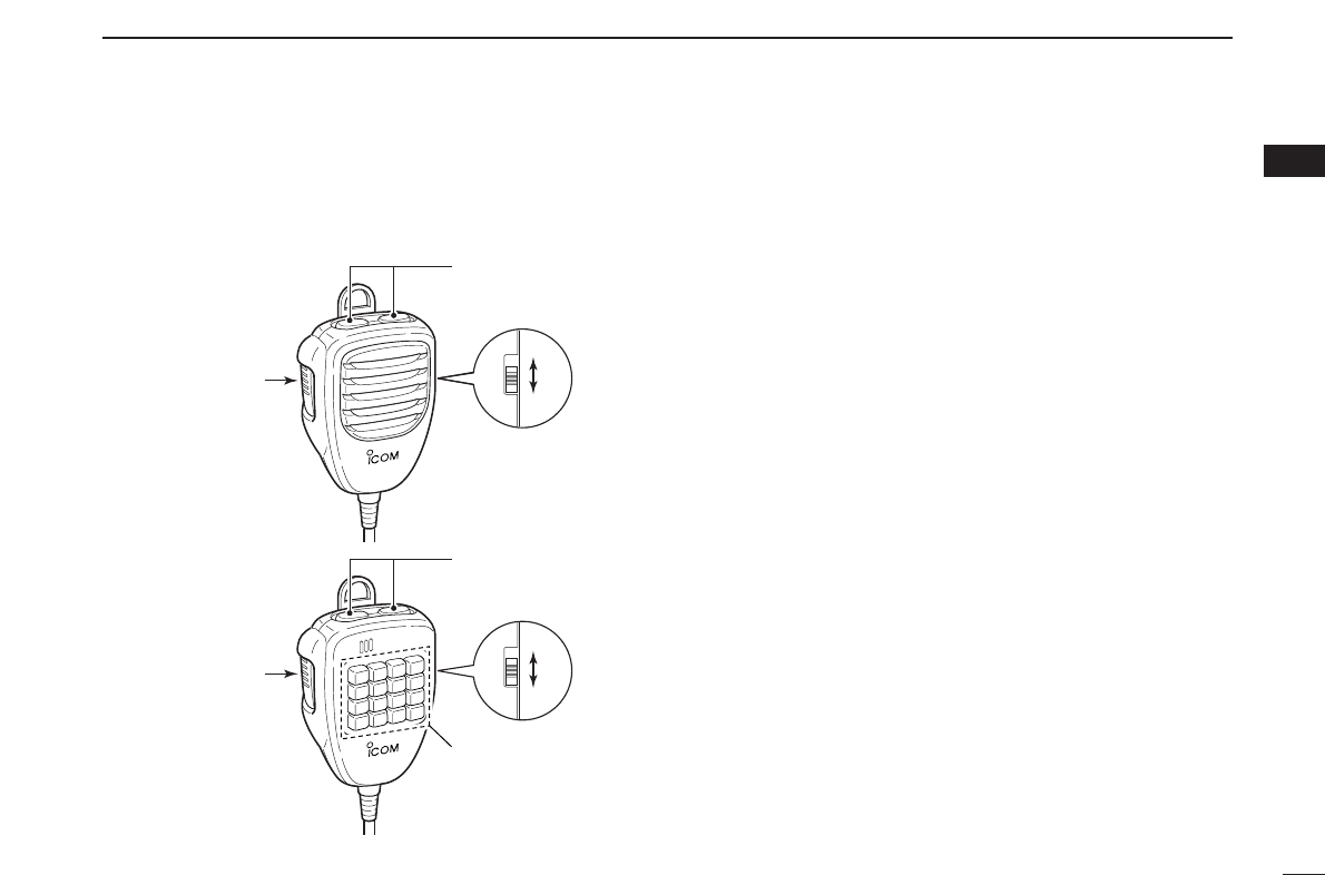
■Optional Microphones
(HM-118N/TN/TAN)
qPTT SWITCH
Push and hold to transmit; release to receive.
wUP/DOWN SWITCHES [UP]/[DN]
➥Push either switch to change operating frequency,
memory channel, set mode setting, etc.
(pgs. 12, 26, 56)
➥Push either switch for 1 sec. to start scanning. (p. 41)
eUP/DN LOCK SWITCH
Slide to toggle [UP]/[DN] switches function ON and OFF.
rKEYPAD (HM-118TN/TAN only)
While pushing [PTT], push the desired key to send the
DTMF code.
w
q
ON
OFF
e
w
r
q
ON
OFF
e
• HM-118N
• HM-118TN/TAN
(DTMF)
11
SETTING A FREQUENCY
2
■Preparation
DTurning power ON/OFF
➥Push [PWR] for 1 sec. to turn power ON and OFF.
DOperating frequency band selection
The ID-800H has 2 m and 70 cm bands for transmission and
reception. In addition, extra frequency bands 127, 220, 350,
500 and 900 MHz bands are available for wide-band receiver
capability (except Taiwan and Korean version).
➥Push [BAND] to select the desired frequency band.
➥Push [BAND] to select the desired band.
DVFO and memory modes
The transceiver has 2 basic operating modes: VFO mode and
memory mode. Select VFO mode first to set an operating fre-
quency.
➥Push [V/MHz•SCAN] to select VFO mode.
•When VFO mode is already selected, the digit below 10 MHz
(the digit below 1 MHz or 100 kHz disappear depending on ver-
sions) disappear. In this case, push [V/MHz•SCAN] again (or
twice or 3 times depending on version).
➥Push [M/CALL•PRIO] to select memory mode.
•“!” indicator appears when memory mode is selected.
➥Push [VFO/LOCK] to select VFO mode.
➥Push [MR/CALL] to select memory mode.
VFO/LOCK
[V/MHz•SCAN]
[M/CALL•PRIO] Appears
BAND
[BAND]
[PWR]
Note that in this manual, sections beginning with a micro-
phone icon (as above), designate operation via the HM-133
microphone.
12
2
SETTING A FREQUENCY
2
■Using the tuning dial
qRotate [DIAL] to set the frequency.
•If VFO mode is not selected, push [V/MHz•SCAN] to select VFO
mode.
•The frequency changes in the selected tuning steps. (p. 13)
w
To change the frequency in 1 MHz (10 MHz for some versions)
steps, push [V/MHz•SCAN], then rotate [DIAL].
•Pushing [V/MHz•SCAN] for 1 sec. starts scan function. If scan
starts, push [V/MHz•SCAN] again to cancel it.
■Using the [Y]/[Z] keys
➥Push [Y] or [Z] to select the desired frequency.
•Pushing [Y]/[Z] for 1 sec. activates a scan. If scan
starts, push [Y]/[Z] or [
CLR
A(MW)] to cancel it.
■Using the keypad
The frequency can be directly set via numeral keys on the mi-
crophone.
zPush [VFO/LOCK] to select VFO mode, if neces-
sary.
xPush [
ENT
C(T-OFF)] to activate the keypad for
digit input.
cPush 6 keys to input a frequency.
•When a digit is mistakenly input, push [
ENT
C(T-OFF)]
to clear the input, then repeat input from the 1st digit.
•Pushing [
CLR
A(MW)] clears input digits and retrieves
the frequency.
Push
Push
Push
Push
[EXAMPLE]: Setting frequency to 145.3625 MHz.
ENT
C
YZ
While 1 MHz tuning step is
selected, the digit below
100 kHz disappear.
While 10 MHz tuning step
is selected, the digit below
1 MHz disappear.
[DIAL]
[V/MHz•SCAN]
13
2SETTING A FREQUENCY
■Tuning step selection
[
Tuning steps are the minimum frequency change increments
when you rotate [DIAL] or push [Y]/[Z] on the microphone.
Independent tuning step for each frequency bands can be set
for individual tuning convenience. The following tuning steps
are available.
•5kHz • 10 kHz • 12.5 kHz • 15 kHz
•20kHz •25kHz • 30 kHz • 50 kHz
•100 kHz • 200 kHz
☞NOTE: For convenience, select a tuning step that matches
the frequency intervals of repeaters in your area.
qPush [BAND] to select the desired frequency band.
•Push [V/MHz•SCAN] to select VFO mode, if necessary.
wPush [SET•LOCK] to enter set mode.
•Rotate [DIAL] to select “SET,” if necessary.
ePush [SET•LOCK] or [S.MW•MW] several times until “TS”
appears as shown below.
rRotate [DIAL] to select the desired tuning step.
tPush [V/MHz•SCAN] to exit set mode.
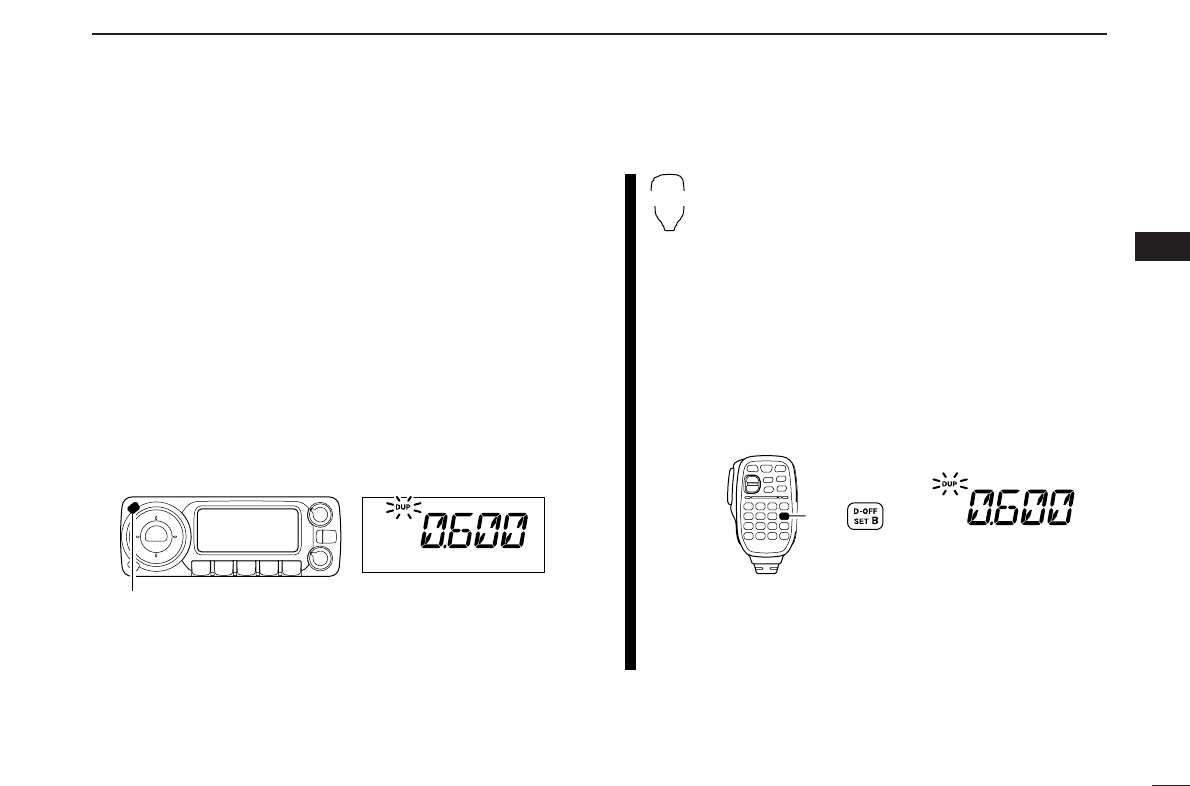
zPush [BAND] to select the desired frequency
band.
•Push [VFO/LOCK] to VFO mode, if necessary.
xPush [
SET
B(D-OFF)] to enter set mode.
•Push [Y] or [Z]to select “SET,” if necessary.
cPush [
SET
B(D-OFF)] or [
ENT
C(T-OFF)] several
times until “TS” appears.
vPush [Y] or [Z] to select the desired tuning step.
bPush [
CLR
A(MW)] to exit set mode.
SET
B
[SET•LOCK]
14
2
SETTING A FREQUENCY
2
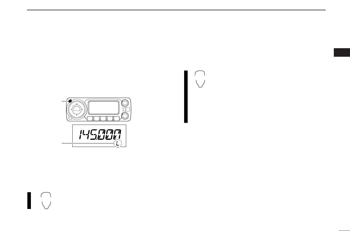
■Lock functions
To prevent accidental frequency changes and unnecessary
function access, use the lock function. The transceiver has 2
different lock functions.
DFrequency lock
This function locks [DIAL] and switches electronically and can
be used together with the microphone lock function.
➥Push [SET•LOCK] for 1 sec. to turn the lock function ON
and OFF.
•[PTT], [MONI•DTMF] (monitor function only), [VOL] and [SQL]
can be used while the channel lock function is in use. Also,
TONE-1, TONE-2, DTMF tones or DTMF memory contents can
be transmitted from the microphone.
➥Push [VFO/LOCK] for 1 sec. to switch the
lock function ON and OFF.
DMicrophone keypad lock
This function locks the microphone keypad.
➥Push [FUNC] then [
SQL
ZD(16KEY-L)] to
switch the microphone keypad lock function
ON and OFF.
•[PTT], [VFO/LOCK], [MR/CALL], [BAND], [Y], [Z],
[F-1], [F-2] and [FUNC] on the microphone can be
used.
•All switches on the transceiver can be used.
•The keypad lock function is released when the
power is turned OFF then ON again.
16KEY-L
VFO/LOCK
[SET•LOCK]
“L” appears
15
BASIC OPERATION
3
■Receiving
qSet the audio level.
➥Push [MONI•DTMF] to open the squelch.
➥Rotate [VOL] to adjust the audio level.
➥Push [MONI•DTMF] to close the squelch.
wSet the squelch level.
➥Rotate [SQL] fully counterclockwise in advance, then ro-
tate [SQL] clockwise until the noise just disappears.
•When interference is received, rotate [SQL] clockwise again
for attenuator operation. (p. 16)
eSet the operating frequency. (pgs. 11, 12)
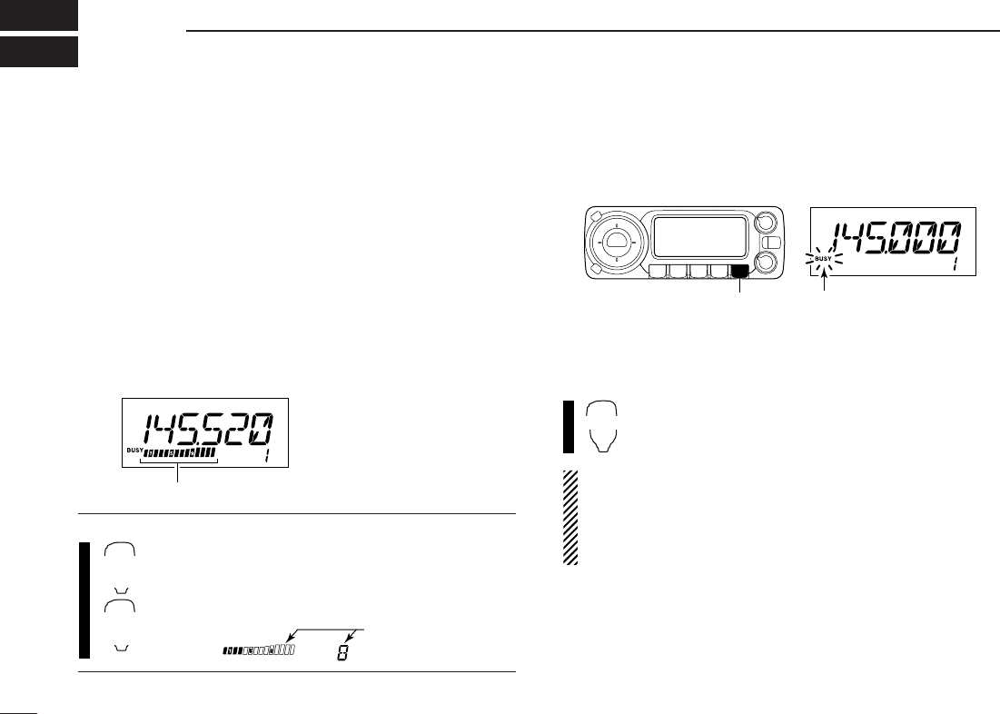
rWhen receiving a signal on the set frequency, squelch
opens and the transceiver emits audio.
•“BUSY” appears and the S/RF
indicator shows the relative
signal strength for the re-
ceived signal.
✔
CONVENIENT!
The audio and squelch level can also be adjusted
with [
VOL
Y(TONE-1)]/[
VOL
Z0(TONE-2)] and
[
SQL
YD(MUTE)]/[
SQL
Z#(16KEY-L)], respectively.
•“VOL” for audio or “SQL” for squelch appears during set.
■Monitor function
This function is used to listen to weak signals without disturb-
ing the squelch setting.
➥Push [MONI•DTMF] to open the squelch.
•“BUSY” blinks.
•Push [MONI•DTMF] again to cancel the function.
➥Push [
MONI
1(BANK)] to open the squelch.
•Push [
MONI
1(BANK)] again to cancel the function.
NOTE: When [SQL] adjustment is set too far clockwise,
(12–17 o’clock position) the squelch attenuator is acti-
vated. To monitor weak signals on the operating frequency,
deactivate the squelch attenuator function. See p. 16 for
details.
MONI
1
[MONI•DTMF] Blinks
Show set level
SQLY/Z
D/#
VOLY/Z
M/0
Appears when receiving a signal
16
3
BASIC OPERATION
3
■Squelch attenuator
The transceiver has an RF attenuator related to the squelch
level setting. Approx. 10 dB attenuation is obtained at maxi-
mum setting.
The squelch attenuator allows you to set a minimum signal
level needed to open the squelch. The attenuator function can
be deactivated in initial set mode.
➥Rotate [SQL] clockwise past the 12 o’clock position to ac-
tivate the squelch attenuator.
•Attenuation level can be adjusted up to 10 dB (approx.) between
12 o’clock and fully clockwise position.
•When setting the squelch from the microphone, a level greater
than ‘19’ activates the squelch attenuator.
NOTE: The squelch attenuator functions even when the
monitor function is in use. Thus set [SQL] control within 10
to 12 o’clock position is recommended when using the
monitor function.
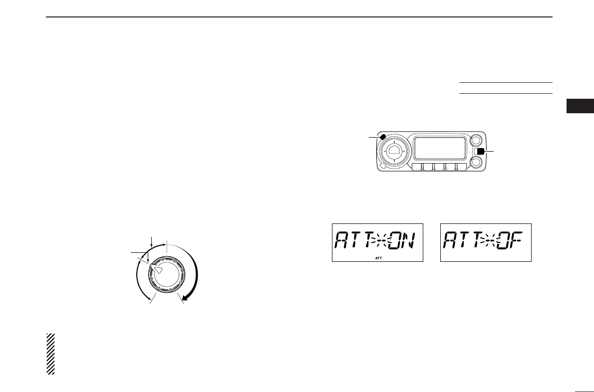
DSquelch attenuator setting
qTurn the transceiver power OFF.
wWhile pushing
[SET•LOCK],
turn the power ON to enter ini-
tial set mode.
ePush
[SET•LOCK] or [S.MW•MW] to select “ATT” (squelch
attenuator) item.
rRotate [DIAL] to toggle the function ON and OFF.
•Select “OF” to deactivate the squelch attenuator function.
tPush [PWR] to exit initial set mode.
[PWR]
[SET•LOCK]
USING
INITIAL SET MODE
Squelch is
open.
Squelch
attenuator
Squelch
threshold
Shallow Deep
Noise squelch
17
3BASIC OPERATION
■Transmitting
☞NOTE: To prevent interference, listen on the channel be-
fore transmitting by pushing [MONI•DTMF] on the front
panel or [
MONI
1(BANK)] on the microphone.
qSelect the frequency band. (p. 11)
wSet the operating frequency. (pgs. 11, 12)
•Select output power if desired. See section at right for details.
ePush and hold [PTT] to transmit.
•“$” appears.
•The S/RF indicator shows the output power selection.
•Aone-touch PTT function is available. See p. 18 for details.
rSpeak into the microphone using your normal voice level.
•DO NOT hold the microphone too close to your mouth or speak
too loudly. This may distort the signal.
tRelease [PTT] to return to receive.
■Selecting output power
The transceiver has 3 output power levels to suit your oper-
ating requirements. Low output powers during short-distance
communications may reduce the possibility of interference to
other stations and will reduce current consumption.
➥Push [LOW•DUP] once or twice to select the output power.
*approx
•The output power can be changed while transmitting.
The microphone can also be used to select output power.
➥Push [
HIGH
4(DTCS)] for high output power;
[
MID
5(DTCSS)] for middle output power; and
[
LOW
6(DTMF)] for low output power.
•The output power can be changed via the microphone
during receive only.
HIGH
4
MID
5
LOW
6
IMPORTANT! (for 55/50 W transmission):
The ID-800H is equipped with protection circuit to protect
the power amplifier circuit from high SWR (Standing Wave
Ratio) and temperature. When a high SWR antenna or no
antenna is connected, or when the transceiver temperature
becomes extremely high, the transceiver reduces transmit
output power to 15 W (approx.) automatically.
CAUTION: Transmitting without an antenna will damage
the transceiver.
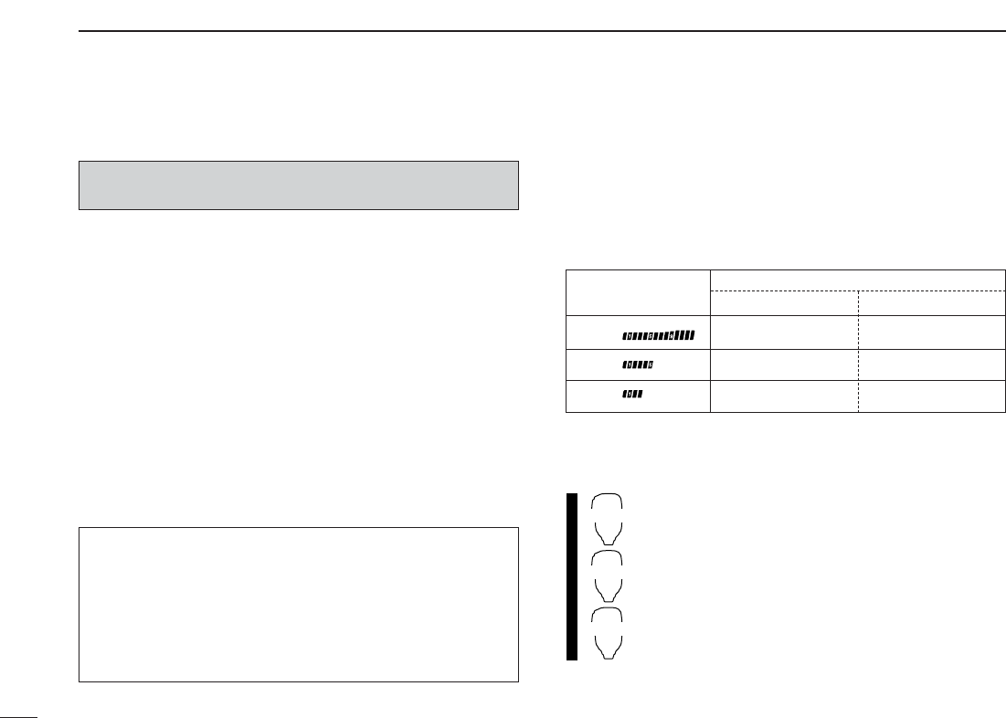
S/RF INDICATOR POWER OUTPUT
VHF UHF
55 W 50 W
15 W* 15 W*
5W* 5W*
High:
Mid:
Low:
■One-touch PTT function
The PTT switch can be operated as a one-touch PTT switch
(each push toggles between transmit/receive). Using this
function you can transmit without pushing and holding the
PTT switch.
To prevent accidental, continuous transmission with this func-
tion, the transceiver has a time-out timer. See p. 62 for de-
tails.
zPush [FUNC] then [
PRIO
3(PTT-M)] to turn the
one-touch PTT function ON.
•The activity indicator lights green.
xPush [PTT] to transmit and push again to re-
ceive.
•Abeep sounds when transmission is started and a
long beep sounds when returning to receive.
•“$” blinks when transmitting with the one-touch
PTT function.
cPush [FUNC] then [
PRIO
3(PTT-M)] to turn the
one-touch PTT function OFF.
•The activity indicator goes out.
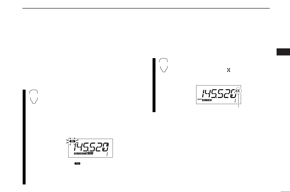
■Audio mute function
This function temporarily mutes the audio without disturbing
the volume setting.
➥Push [FUNC] then [
SQL
YD(MUTE)] to mute
audio signals.
•The audio mute indicator, “ ” appears.
•Push [
CLR
A(MW)] (or any other key) to cancel the
function.
Appears
MUTE
indicator blnks
PTT-M
18
3
BASIC OPERATION
3
19
REPEATER OPERATION
4
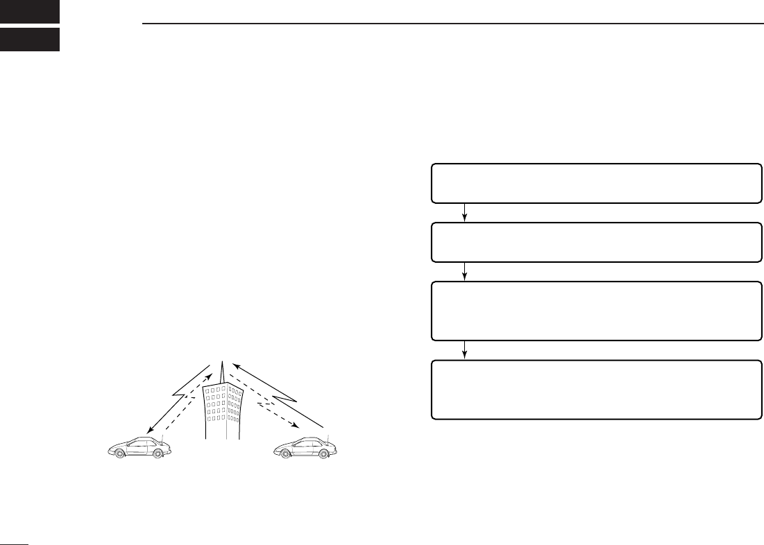
Repeaters allow you to extend the operational range of your
radio because a repeater has much higher output power than
the typical transceiver.
Normally, a repeater has independent frequencies for each
receiver and transmitter.
Asubaudible tone may also be required to access a repeater.
Reference amateur radio hand books and local ham maga-
zines for details of local repeaters such as repeater input/out-
put frequencies and locations.
•Repeater operation flow chart
•The ID-800H USA version has the auto repeater function. Thus the
steps 3 and 4 may not be necessary, depending on the setting.
•Repeater settings can be stored into a memory channel.
Step 3:
Set the duplex (shifting) direction (– duplex or +duplex).
- Set the offset frequency (shifting value), if required.
Step 4:
Set the subaudible tone (repeater tone) encoder function ON.
- Set the subaudible tone frequency, if required.
Step 1:
Set the desired band to operate the repeater.
Step 2:
Set the desired receive frequency (repeater output frequency).
Repeater example;
Receives the 444.540 MHz signal
and the detected audio signals are
transmitted on 449.540 MHz simul-
taneously.
Station A:
Tx: 444.540 MHz
Rx: 449.540 MHz
Station B:
Tx: 444.540 MHz
Rx: 449.540 MHz
■General
20
4
REPEATER OPERATION
4
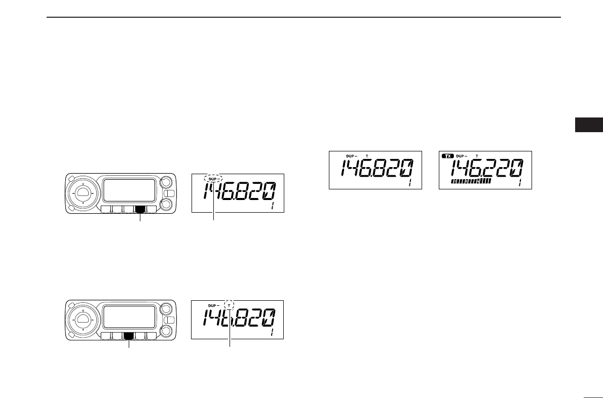
■Accessing a repeater
qSet the receive frequency (repeater output frequency).
(pgs. 11, 12)
wPush [LOW•DUP] for 1 sec. one or two times, to select
minus duplex or plus duplex.
•“DUP–” or “DUP” appears to indicate the transmit frequency for
minus shift or plus shift, respectively.
•When the auto repeater function is turned ON (available for the
USA version only), steps wand eare not necessary. (p. 25)
ePush [TONE•T-SCAN] several times to turn ON the sub-
audible tone encoder, according to repeater requirements.
•“T” appears
•88.5 Hz is set as the default; refer to p. 22 for tone frequency
settings.
•When the repeater requires a different tone system, see p. 23.
rPush and hold [PTT] to transmit.
•The displayed frequency automatically changes to the transmit
frequency (repeater input frequency).
•If “OFF” appears, confirm that the offset frequency (p. 24) is set
correctly.
tRelease [PTT] to receive.
yPush [MONI•DTMF] to check whether the other station’s
transmit signal can be received directly.
uTo return to simplex operation, push [LOW•DUP] once or
twice, to clear the “DUP–” or “DUP” indicator.
iTo turn OFF the subaudible tone encoder, push [TONE•T-
SCAN] several times until no tone indicators appear.
While transmittingWhile receiving
[TONE•T-SCAN] “T” appears
[LOW•DUP] “DUP–” or “DUP” appears
21
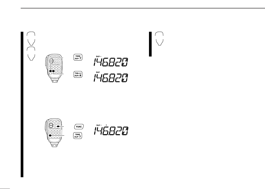
4REPEATER OPERATION
zSet the receive frequency (repeater output fre-
quency). (pgs. 11, 12)
xPush [
DUP
–7(TONE)] to select minus duplex;
push [
DUP
+8(TSQLS)] to select plus duplex.
cPush [FUNC] then [
DUP
–7(TONE)] to turn ON
the subaudible tone encoder according to re-
peater requirements.
•Refer to p. 22 for the tone frequency setting.
•When the repeater requires a different tone system,
see p. 23.
vPush and hold [PTT] to transmit.
bRelease [PTT] to receive.
nPush [
MONI
1(BANK)] to check whether the
other station’s transmit signal can be received
directly.
mPush [
SIMP
9(TSQL)] to return to simplex opera-
tion.
•“DUP” or “DUP–” indicator disappears.
,To turn OFF the subaudible tone encoder, push
[FUNC] then [
ENT
C(T-OFF)].
SIMP
9
Push ,
then .
Push
Push
DUP–
7
DUP+
8
22
4
REPEATER OPERATION
4
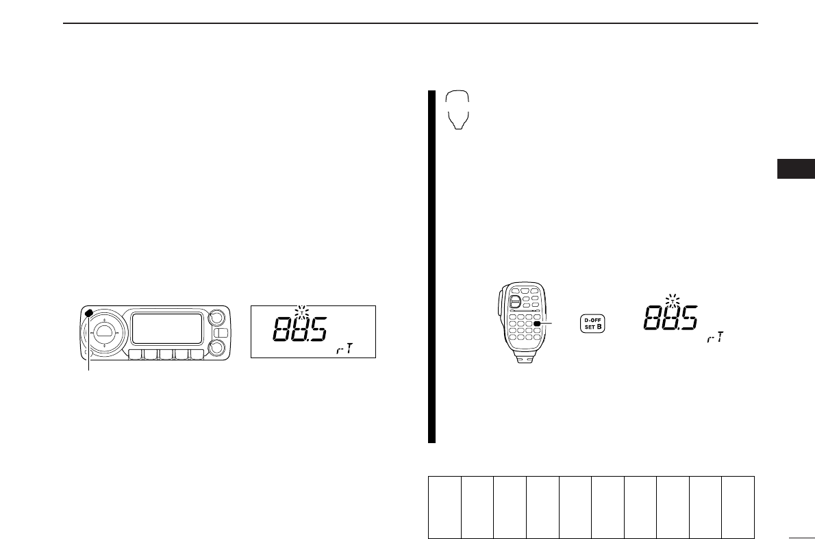
■Subaudible tones [
(Encoder function)
DSubaudible tones
qSelect the frequency band, mode/channel you wish to set
the subaudible tones, such as VFO mode or memory/call
channel.
wPush [SET•LOCK] to enter set mode.
•Rotate [DIAL] to select “SET,” if necessary.
ePush [SET•LOCK] or [DUP•MONI] several times until “T”
and “rT” appear; or until “T SQL” and “CT” appear for tone
squelch or pocket beep use.
•When “d” is displayed in place of the 100 MHz digit, cancel the
DTMF memory encoder in advance. (p. 50)
rRotate [DIAL] to select and set the desired subaudible fre-
quency.
tPush [V/MHz•SCAN] to exit set mode.
☞NOTE: The subaudible tone encoder frequency can be set
in a memory/call channel temporarily. However, the set fre-
quency is cleared once another memory channel or VFO
mode is selected. To store the tone frequency permanently,
overwrite the channel information.
zSet the frequency band, mode/channel you wish
to set the subaudible tones, such as VFO mode
or memory/call channel.
•The subaudible tone frequency is independently pro-
grammed into each mode or channel.
xPush [
SET
B(D-OFF)] to enter set mode.
•Push [Y] or [Z] to select “SET,” if necessary.
c
Push [
SET
B(D-OFF)] or [
ENT
C(T-OFF)] several
times until “T”
and “rT” appears; or until “T SQL”
and “CT” appears for tone squelch or pocket
beep use.
•
When “d” is displayed in place of the 100 MHz digit,
cancel the DTMF memory encoder in advance. (p. 50)
vPush [Y] or [Z] to select and set the desired
subaudible tone frequency.
•Push and hold [Y]/[Z] to change the above tones
continuously.
bPush [
CLR
A(MW)] to exit set mode.
•Subaudible tone frequency list (unit: Hz)
67.0
69.3
71.9
74.4
77.0
79.7
82.5
85.4
88.5
91.5
94.8
97.4
100.0
103.5
107.2
110.9
114.8
118.8
123.0
127.3
131.8
136.5
141.3
146.2
151.4
156.7
159.8
162.2
165.5
167.9
171.3
173.8
177.3
179.9
183.5
186.2
189.9
192.8
196.6
199.5
203.5
206.5
210.7
218.1
225.7
229.1
233.6
241.8
250.3
254.1
Push
SET
B
[SET•LOCK] “T” and “rT” appears
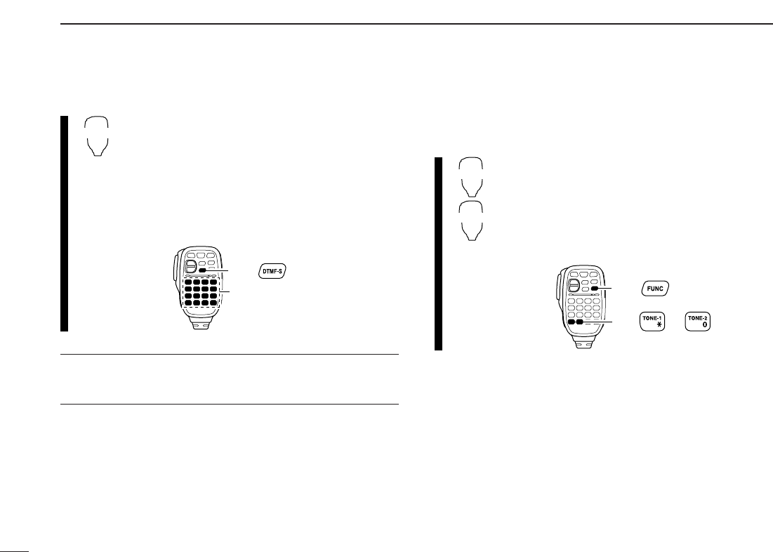
DDTMF tones
➥Push [DTMF-S], then push the keys of the de-
sired DTMF digits.
•The function indicator lights green.
•0–9, A–D, M(E) and #(F) are available.
•When “d” is displayed in place of the 100 MHz digit,
cancel the DTMF memory encoder in advance.
(p. 50)
•Push [DTMF-S] again to return the keypad to nor-
mal function control.
✔
For your convenient!
The transceiver has 16 DTMF memory channels for au-
topatch operation. See p. 48 for details.
D1750 Hz tone
The microphone has 1750 Hz tone capability, used for ring
tone when calling, etc.
zPush [FUNC].
•The function indicator lights orange.
xPush [MM(TONE-1)] to transmit a 1750 Hz tone
call signal for 0.5 sec.; push and hold
[0(TONE-2)] to transmit a 1750 Hz tone call
signal for an arbitrary period.
•The function indicator goes out automatically.
Push ,
then or .
TONE-1
TONE-2
then push desired keys.
Push ,
DTMF-S
23
4REPEATER OPERATION
24
4
REPEATER OPERATION
4
■Offset frequency [
When communicating through a repeater, the transmit fre-
quency is shifted from the receive frequency by an amount
determined by the offset frequency.
Independent offset frequencies can be set for each operating
frequency.
qPush [BAND] to select the desired frequency band.
wSelect the desired mode/channel you wish to set the offset
frequency, such as VFO mode or memory/call channel.
•The offset frequency can be independently programmed into
each mode or channel.
ePush [SET•LOCK] to enter set mode.
•Rotate [DIAL] to select “SET,” if necessary.
rPush [SET•LOCK] or [S.MW•MW] until “DUP” and offset
frequency appear.
tRotate [DIAL] to set the desired offset frequency.
yPush [V/MHz•SCAN] to exit set mode.
zPush [BAND] to select the desired frequency
band.
•Enter the desired frequency via the keypad if neces-
sary.
xSelect the desired mode/channel you wish to
set the offset frequency, such as VFO mode or
memory/call channel.
•The offset frequency can be independently pro-
grammed into each mode or channel.
cPush [
SET
B(D-OFF)] to enter set mode.
•Push [Y] or [Z]to select “SET,” if necessary.
vPush [
SET
B(D-OFF)] or [
ENT
C(T-OFF)] until
“DUP” and offset frequency appear.
bPush [Y] or [Z] to set the desired offset.
•Direct frequency entry from the keypad is not possi-
ble.
nPush [
CLR
A(MW)] to exit set mode.
☞NOTE: The offset frequency can be set in a memory/call
channel temporarily. However, the set frequency is cleared
once another memory channel or VFO mode is selected.
To store the offset frequency permanently, overwrite the
channel information.
Push
SET
B
[SET•LOCK] “DUP” and offset frequency appear
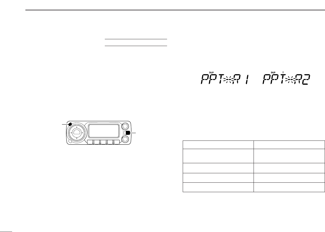
■Auto repeater
(U.S.A. version only)
The USA version automatically activates the repeater settings
(DUP– or DUP+ and tone encoder ON/OFF) when the operating
frequency falls within the general repeater output frequency
range and inactivate them when outside of the range.
DSetting the auto repeater function ON/OFF
qPush [PWR] to turn power OFF.
wWhile pushing [SET•LOCK], turn power ON to enter initial
set mode.
ePush [SET•LOCK] or [S.MW•MW] several times until the
“RPT” display appears as shown above right.
rRotate [DIAL] to select the auto repeater function from
“R1,” “R2” or OFF.
•“R1”: auto repeater is ON, tone encoder is OFF.
•“R2”: auto repeater is ON, tone encoder is ON.
tPush [PWR] to exit initial set mode.
DFrequency range and offset direction
Auto DUP: ON
Auto tone set: OFF
Auto DUP: ON
Auto tone set: ON
[PWR]
[SET•LOCK]
USING
INITIAL SET MODE
25
4REPEATER OPERATION
Frequency range Duplex direction
145.200–145.495 MHz “DUP–” appears
146.610–146.995 MHz
147.000–147.395 MHz “DUP” appears
442.000–444.995 MHz “DUP” appears
447.000–449.995 MHz “DUP–” appears
26
5
MEMORY OPERATION
4
5
■General description
The transceiver has 512 memory channels including 10 scan
edge memory channels (5 pairs), and 2 call channels. Each of
these channels can be individually programmed with operat-
ing frequency (pgs. 11, 12), duplex direction (p. 21) and off-
set (p. 24), subaudible tone encoder or tone squelch and its
tone frequency (pgs. 20, 22, 52, 53) and skip information*
(p. 44).
In addition, a total of 10 memory banks, A to J, are available
for usage by group, etc.
*except for scan edge memory channels.
■Memory channel selection
DUsing the tuning dial
qPush [M/CALL•PRIO] several times to select memory
mode.
•“!” indicator appears
wRotate [DIAL] to select the desired memory channel.
•Programmed memory channels only can be selected.
DUsing the [Y]/[Z] keys
zPush [MR/CALL] to select memory mode.
xPush [Y] or [Z] to select and set the desired
memory channel.
•Pushing [Y]/[Z] for 1 sec. activates a scan.
•If scan is activated, push [Y]/[Z] again or push
[
CLR
A(MW)] to stop it.
DUsing the keypad
zPush [MR/CALL] to select memory mode.
xPush [
ENT
C(T-OFF)] to activate the keypad
for numeral input.
cPush 3 appropriate digit keys to input a chan-
nel number.
•Blank channel can be selected.
•Push only 1 appropriate digit key, [
MONI
1(BANK)],
[
SCAN
2(T-SCAN)], [
PRIO
3(PTT-M)],
[
HIGH
4(DTCS)] or [
MID
5(DTCSS)] then push
[MM(TONE-1)] or [
SQL
Z#(16KEY-L)] to select scan
edge channels. “MM” and “#” can be used for “A”
and “b” respectively.
MR/CALL
MR/CALL
Y/Z
[M/CALL•PRIO] “!” appears
27
5MEMORY OPERATION
■Programming a memory channel
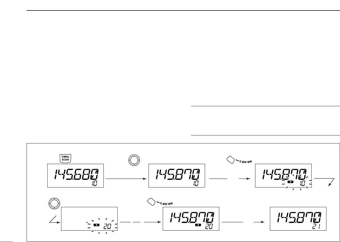
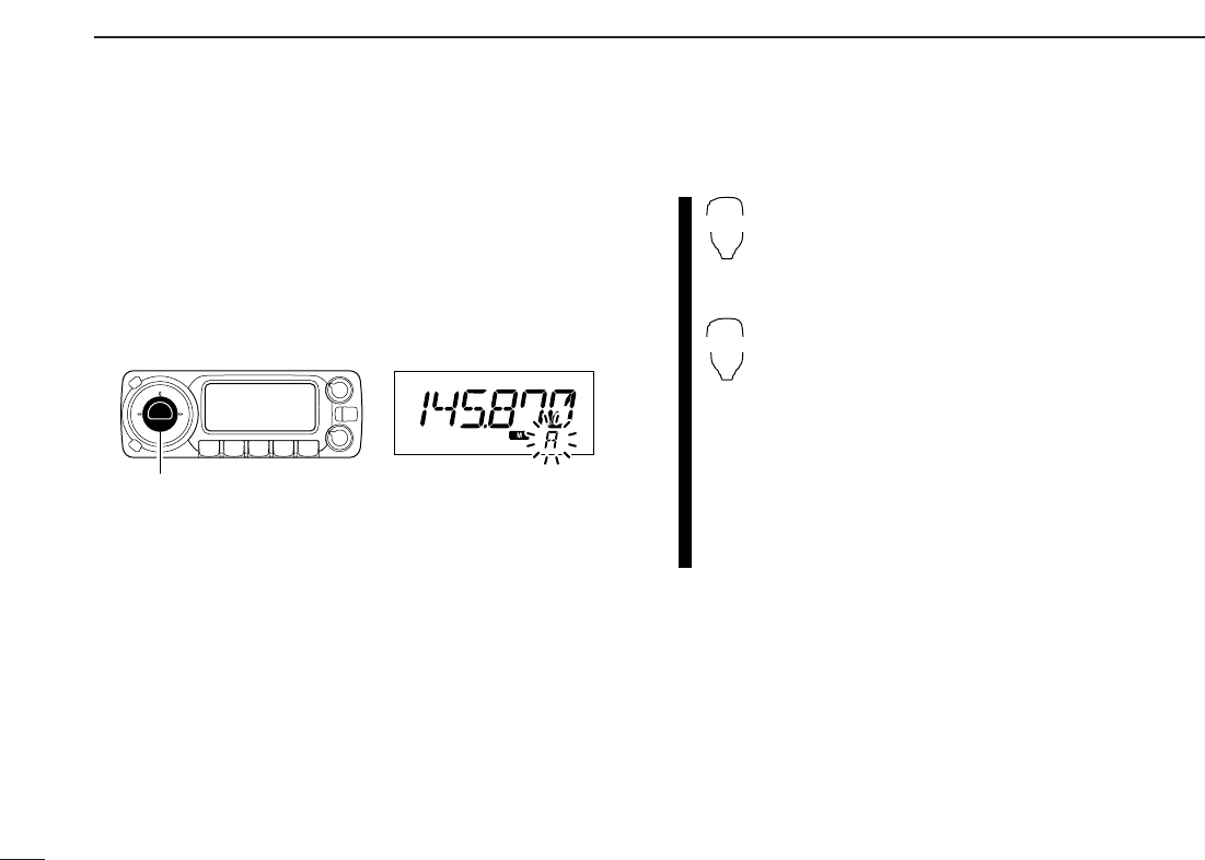
[EXAMPLE]: Programming 145.870 MHz into memory channel 20 (blank channel) via the controller.
Push Rotate for setting frequency, etc. Push .
Rotate Push for 1 sec. and continue to push
➠
Beep
“
Beep
Beep
Beep
“
“
“
“
“
Beep
“
VFO settings, including the set mode contents such as sub-
audible tone frequency or offset, can be programmed into a
memory channel.
qSet the desired frequency.
➥Push [V/MHz•SCAN] to select VFO mode.
➥Set the frequency using [DIAL].
➥Set other data (e.g. tone frequency, duplex information,
etc.) if required.
wPush [S.MW•MW].
•“!” indicator and the memory channel number blink.
eRotate [DIAL] to select the memory channel to be pro-
grammed.
•Memory channels not yet programmed are blank.
rPush [S.MW•MW] for 1 sec. to program.
•3 beeps sound
•Memory channel number automatically increases when contin-
uing to push [S.MW•MW] after programming.
✔CONVENIENT
Memory programming can be performed in versatile ways
e.g. memory channel to the same (or different) memory chan-
nel, memory channel to the call channel, etc.
28
5
MEMORY OPERATION
5
DProgramming a memory channel via the microphone
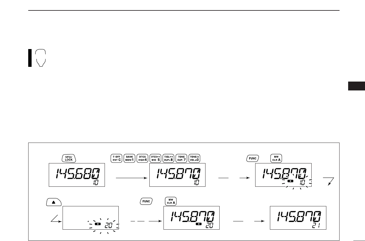
[EXAMPLE]: Programming 145.870 MHz into memory channel 20 (blank channel) via the microphone.
Push 10 times
Beep
“
Beep
“
Beep
Beep
Beep
“
“
“
“
“
Push Push then
Push then for 1 sec. and continue to push
➠
The microphone can also be used to program mem-
ory channels.
zSet the desired frequency in VFO mode.
➥Push [VFO/LOCK] to select VFO mode.
➥Set the frequency using the keypad.
➥Set other data (e.g. offset frequency, duplex direction, sub-
audible tone encoder ON/OFF and its frequency), if neces-
sary.
xPush [FUNC] then [
CLR
A(MW)] momentarily.
cPush [Y] or [Z] to select the memory channel.
•Direct numeral input cannot be used.
vPush [FUNC] then [
CLR
A(MW)] for 1 sec. to program.
➥3 beeps may sound and the VFO contents (including
the subaudible tone frequency, etc.) are programmed.
➥Memory channel number increases when continuing to
push [
CLR
A(MW)] after programming.
MW
29
5MEMORY OPERATION
■
Copying memory contents
This function copies a memory channel’s contents to VFO (or
another memory/call channel). This is useful when searching
for signals around a memory channel frequency and for re-
calling the offset frequency, subaudible tone frequency etc.
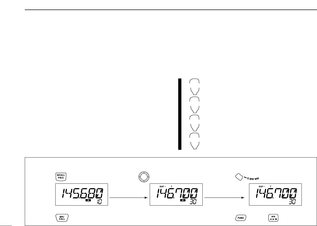
DMemory/call➪VFO
qSelect the desired memory or call channel.
➥Push [M/CALL•PRIO] several times to select memory
mode or call channel, then rotate [DIAL] or push [BAND]
to select the desired memory or call channel respec-
tively.
wPush [S.MW•MW] for 1 sec. to transfer the selected mem-
ory/call channel contents to the VFO.
•VFO mode is selected automatically.
zSelect the memory/call channel to be
transferred.
➥Push [MR/CALL] to select memory mode,
then select the desired memory channel
via [Y]/[Z] or keypad.
➥Push [MR/CALL] for 1 sec. then push
[BAND] to select the desired call channel.
xPush [FUNC], then [
CLR
A(MW)] for 1 sec. to
transfer the selected memory/call channel
contents to the VFO.
•VFO mode is selected automatically.
MR/CALL
MW
BAND
[Y]/[Z]
[EXAMPLE]: Transferring memory channel 30 contents to VFO.
Push to select memory mode.
Front panel operation:
HM-133 operation:
Push to select memory mode.
Rotate for selecting memory channel.
Push [Y]/[Z] to select memory channel.
Push for 1 sec.
Push then push for 1 sec.
30
5
MEMORY OPERATION
5
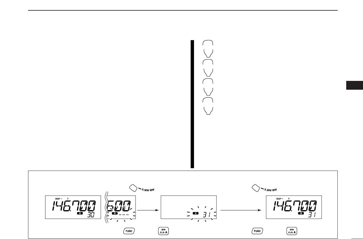
DMemory/call➪memory/call
qSelect the memory/call channel to be transferred.
➥Push [M/CALL•PRIO] several times to select memory
mode or call channel, then rotate [DIAL] or push [BAND]
to select the desired memory or call channel respec-
tively.
wPush [S.MW•MW] momentarily.
•“!” indicator and “-- -- --” indication blink, and shows VFO con-
ditions.
eRotate [DIAL] to select the target memory channel.
•“C1” or “C2” blinks when the call channel is selected.
•Scan edge channels, 1A/1B, 2A/2B, 3A/3B, 4A/4B, 5A/5B can
also be selected.
rPush [S.MW•MW] for 1 sec. to transfer the selected mem-
ory/call channel contents to the target memory.
•The targeted memory and transferred contents are indicated.
zSelect the memory/call channel to be trans-
ferred.
➥Push [MR/CALL] to select memory mode,
then select the desired memory channel
via [Y]/[Z] or keypad.
➥Push [MR/CALL] for 1 sec. then push
[BAND] to select the desired call channel.
x
Push [FUNC], then [
CLR
A(MW)] momentarily.
•“!” indicator and “-- -- --” indication blink, and
shows VFO conditions.
cPush [Y]/[Z] to select the target memory
channel.
•
“C1” or “C2” blinks when the call channel is selected.
•Scan edge channels can also be selected.
•The keypad cannot be used for the selection.
vPush [FUNC] then push [
CLR
A(MW)] for
1sec. to transfer the selected memory/call
channel contents to the target channel.
•The targeted channel and transferred contents
are indicated.
MR/CALL
MW
BAND
[Y]/[Z]
[EXAMPLE]: Transferring memory channel 30 contents to channel 31.
Select the target channel. Push for 1 sec.
Push then push for 1 sec.
Select the memory channel, then push .
Select the memory channel, push then push .
Front panel operation:
HM-133 operation:
31
5MEMORY OPERATION
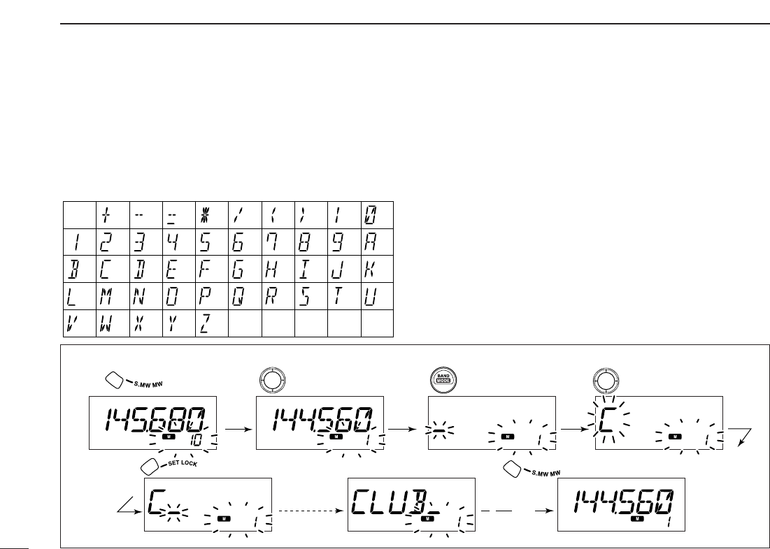
■Programming channel names
Each memory channel and the call channel can be pro-
grammed with an alphanumeric channel name for easy
recognition and can be indicated independently by channel.
Names can be a maximum of 6 characters— see the table
below for available characters.
qPush [S.MW•MW] momentarily.
•“!” and memory channel number blink.
wRotate the tuning dial to select the desired memory or call
channel.
ePush [BAND] to select the memory name programming
condition.
•Frequency readouts disappear and a cursor blinks.
rRotate the tuning dial to select the desired character.
•The selected character blinks.
tPush [SET•LOCK] to move the cursor to the right.
yRepeat steps rand tuntil the desired channel names
are displayed.
uPush [S.MW•MW] for 1 sec. to program the name and exit
the channel name programming condition.
(1)
(B)
(L)
(V)
(+)
(2)
(C)
(
M
)
(
W
)
(–)
(3)
(
D
)
(N)
(X)
(=)
(4)
(E)
(O)
(Y)
(✱)
(5)
(F)
(P)
(Z)
(/)
(6)
(G)
(
Q
)
(space)
(7)
(()
(
H
)
(
R
)
())
(8)
(I)
(S)
(|)
(9)
(J)
(T)
(0)
(A)
(
K
)
(U)
[EXAMPLE]: Programming “CLUB” into memory channel 1.
RotatePush Push Rotate
Push for 1 sec.
Repeat the
previous
steps.
Beep
Beep
Beep
“
“
“
“
“
Push
32
5
MEMORY OPERATION
5
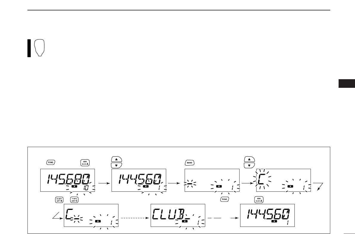
Channel names can also be programmed via the mi-
crophone.
zPush [FUNC] then [
CLR
A(MW)] momentarily.
•“!” and memory channel number blink.
xPush [Y]/[Z] to select the memory/call channel to be as-
signed memory names.
cPush [BAND].
•Frequency readouts disappear and a cursor blinks.
vPush [Y]/[Z] to select the desired character.
•The selected character blinks.
bPush [
SET
B(D-OFF)] or [
ENT
C(T-OFF)] to move the cur-
sor to left or right, respectively.
nRepeat steps vand buntil the desired channel names
are displayed.
mPush [FUNC] then [
CLR
A(MW)] for 1 sec. to program the
name and exit the channel name programming condition.
[EXAMPLE]: Programming “CLUB” into memory channel 1.
Push
Repeat the
previous
steps.
Beep
Beep
Beep
“
“
“
“
“
Push to select the channel. Push to select the character
Push or to move the cursor.
Push , then push .
Push , then push for 1 sec.
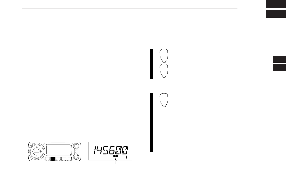
5MEMORY OPERATION
33
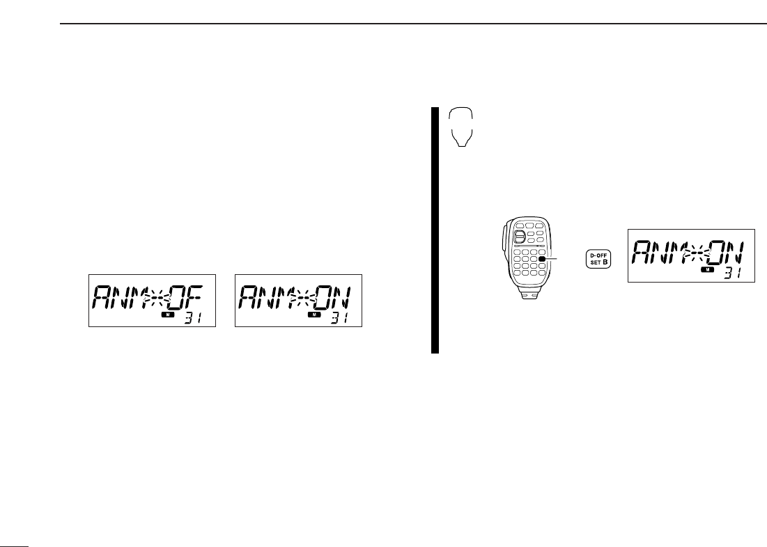
DDTo indicate the channel name [
The channel name indication can be set for independent
memory channels.
qPush [M/CALL•PRIO] to select the memory mode.
wRotate [DIAL] to select the desired memory channel to be
indicated the channel name.
ePush [SET•LOCK] to enter set mode.
•Rotate [DIAL] to select “SET,” if necessary.
rPush [SET•LOCK] or [S.MW•MW] several times to select
“ANM” item.
tRotate [DIAL] to turn the memory name indication ON.
yPush [V/MHz•SCAN] to exit set mode.
NOTE: When no memory name is programmed, the stored
frequency is displayed.
zPush [MR/CALL] to select the memory mode.
xPush [Y] or [Z] to select the desired memory
channel to be indicated the channel name.
cPush [
SET
B(D-OFF)] to enter set mode.
•Push [Y] or [Z]to select “SET,” if necessary.
vPush [
SET
B(D-OFF)] or [
ENT
C(T-OFF)] until
“ANM” appear.
bPush [Y] or [Z] to set the memory name indi-
cation ON and OFF.
nPush [
CLR
A(MW)] to exit set mode.
Push
SET
B
5
MEMORY OPERATION
34
5
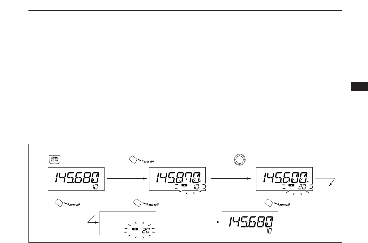
■Memory clearing
Contents of programmed memories can be cleared (blanked),
if desired.
qPush [V/MHz•SCAN] to select VFO mode.
wPush [S.MW•MW] momentarily.
•“!” indicator and the memory channel number blink.
eRotate [DIAL] to select the memory channel to be cleared.
•Memory channels not yet programmed are blank.
rPush [S.MW•MW] momentarily, then push [S.MW•MW]
again for 1 sec.
☞This operation must be performed within 1.5 sec.
•3 beeps sound, then the frequency is cleared.
•“!” indicator and the channel number blink continuously.
•When clearing the call channel, the current VFO conditions are
re-programmed into the call channel automatically.
tPush [V/MHz•SCAN] to return to VFO mode.
☞NOTE: Be careful!— the contents of cleared memories
CANNOT be recalled.
[EXAMPLE]: Clearing memory channel 20.
Push to select VFO. Rotate for selecting memory channel.
Push .
Push any switch, except .
Push momentarily, then push again for 1 sec.
Beep
Beep
Beep
“
“
“
“
“
35
5MEMORY OPERATION
■Memory bank selection
The ID-800H has a total of 10 banks (A to J). Regular memory
channels, 1 to 500, are assigned into the desired bank for
easy memory management.
qPush [M/CALL•PRIO] several times to select memory
mode, if desired.
wPush [BAND] to select memory bank condition.
•Bank’s initial blinks
eRotate [DIAL] to select the desired bank, A to J.
•Banks that have no programmed contents are skipped.
rPush [BAND] to set the bank.
•Bank’s initial stops blinking.
tRotate [DIAL] to select the contents in the bank.
•No channel numbers are displayed for memory bank operation.
yTo return to regular memory condition, push [BAND] twice.
zPush [MR/CALL] to select memory mode, if de-
sired.
xPush [FUNC] then [
MONI
1(BANK)] to select
memory bank condition.
•Bank’s initial blinks
cPush [Y]/[Z] to select the desired bank, A to J.
•Only programmed memory bank can be selected.
vPush [
CLR
A(MW)] to set the bank.
•Bank’s initial stops blinking.
bPush [Y]/[Z] to select the desired contents in
the bank.
•No channel numbers are displayed for memory
bank operation.
nTo return to regular memory condition, push
[FUNC], [
MONI
1(BANK)] then push
[
CLR
A(MW)].
BANK
[Y]/[Z]
[BAND] Bank initial blinks
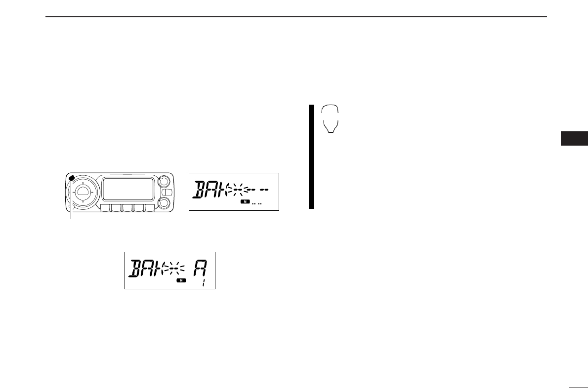
36
5
MEMORY OPERATION
5
■Memory bank setting
[
qPush [M/CALL•PRIO] several times to select memory
mode, then select the desired memory channel via [DIAL].
wPush [SET•LOCK] to enter set mode.
•Rotate [DIAL] to select “SET,” if necessary.
ePush [SET•LOCK] or [S.MW•MW] several times until
“BAK” appears.
rRotate [DIAL] to select the desired bank to be set.
tPush [V/MHz•SCAN] to exit set mode.
zPush [MR/CALL] then select the desired mem-
ory channel via [Y]/[Z] or keypad.
xPush [
SET
B(D-OFF)] to enter set mode.
•Push [Y] or [Z]to select “SET,” if necessary.
cPush [
SET
B(D-OFF)] or [
ENT
C(T-OFF)] several
times until “BAK” appears.
vPush [Y]/[Z] to select the desired bank to be
set.
bPush [
CLR
A(MW)] to set the channel into the
bank and exit set mode.
SET
B
[SET•LOCK] Bank’s initial blinks
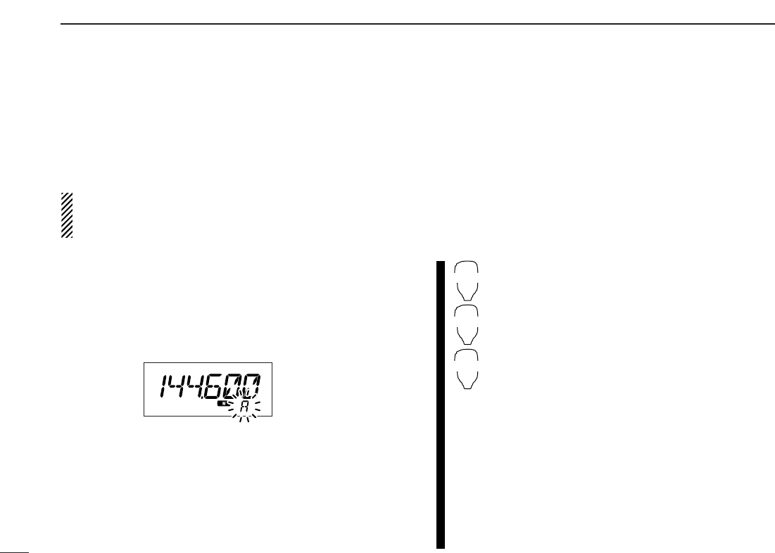
37
5MEMORY OPERATION
■Transferring bank contents
[
Contents of programmed memory banks can be cleared or
transferred to another bank.
INFORMATION: Even if the memory bank contents are
cleared, the memory channel contents still remain pro-
grammed.
qSelect the desired bank contents to be transferred or
erased.
➥Push [M/CALL•PRIO] several times to select memory
mode.
➥Push [BAND] then rotate [DIAL] to select the desired
memory bank.
•Bank’s initial blinks.
➥Push [BAND] to select the bank then rotate [DIAL] to se-
lect the desired contents.
•Bank’s initial stops blinking.
wPush [SET•LOCK] to enter set mode.
•Rotate [DIAL] to select “SET,” if necessary.
ePush [SET•LOCK] or [S.MW•MW] several times until
“BAK” appears.
•The bank’s initial for the selected memory channel is displayed.
rRotate [DIAL] to select the desired bank initial to transfer
or erase.
•Select “-- --” indication when erasing the contents from the bank.
tPush [V/MHz•PRIO] to set the bank and exit set mode.
yRepeat steps qto rfor transferring or erasing an an-
other banks contents.
zSelect the desired bank contents to be trans-
ferred or erased.
➥Push [MR/CALL] to select memory mode.
➥Push [FUNC], [
MONI
1(BANK)] then select
the desired memory bank via [Y]/[Z].
➥Push [
CLR
A(MW)] to select the bank then
select the desired contents via [Y]/[Z].
xPush [
SET
B(D-OFF)] to enter set mode.
•Push [Y] or [Z]to select “SET,” if necessary.
cPush [
SET
B(D-OFF)] or [
ENT
C(T-OFF)] several
times until “BAK” appears.
vPush [Y]/[Z] to select the desired bank initial to
transfer or erase.
•Select “-- --” indication when erasing the contents
from the bank.
bPush [
CLR
A(MW)] to set the bank and exit set
mode.
nRepeat steps zto bfor transferring or eras-
ing an another banks contents.
BANK
[Y]/[Z]
SET
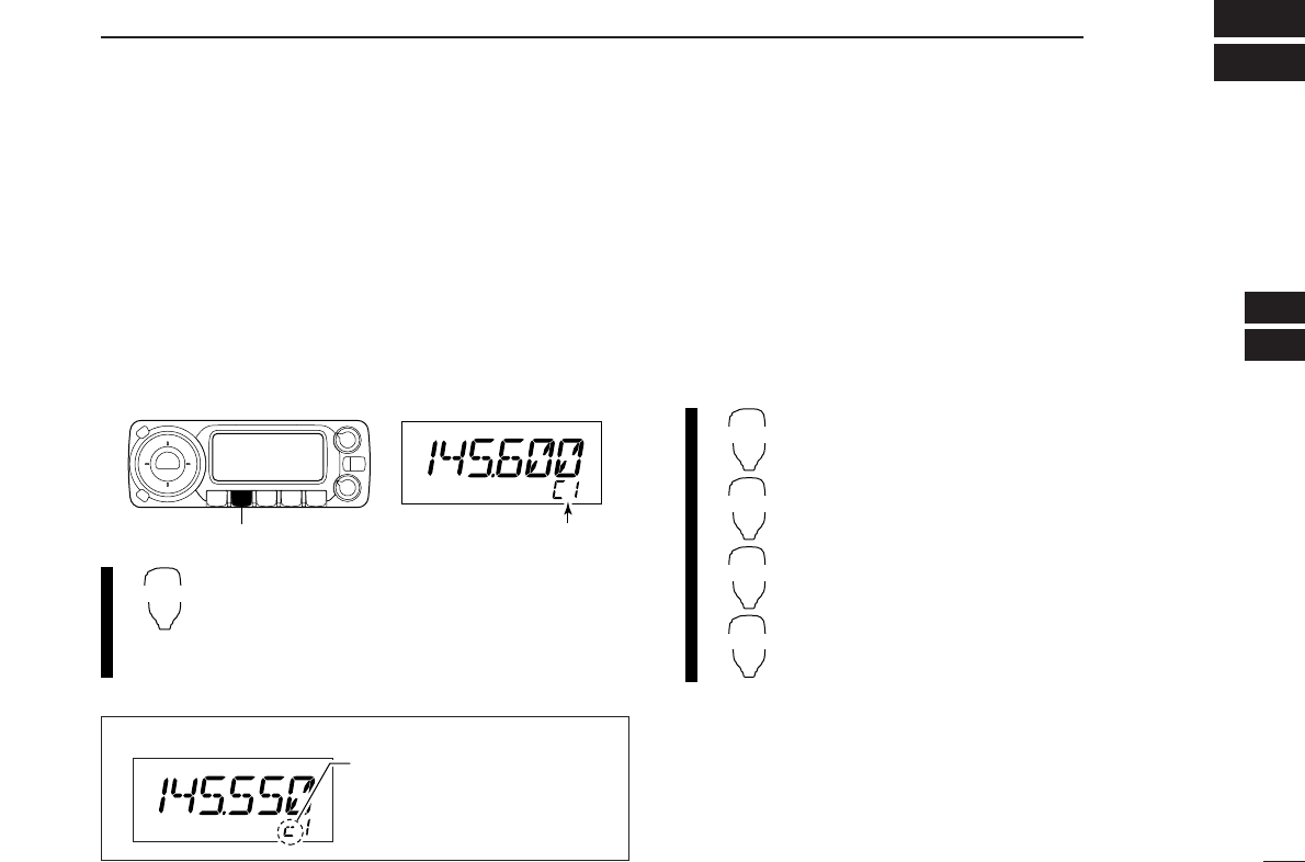
38
6
CALL CHANNEL OPERATION
5
6
■Call channel selection
Call channel is pre-programmed memory channel that can be
accessed by simply pushing call channel button.
➥Push [M/CALL•PRIO] several times to select the call chan-
nel mode then push [BAND] to select the desired call
channel.
•“C1” or “C2” appears instead of memory channel number indi-
cation.
•
Push [M/CALL•PRIO] several times to select memory mode, or
push [V/MHz•SCAN] to select VFO mode.
➥Push [MR/CALL] for 1 sec. to select the call
channel mode then push [Y]/[Z] to select the
desired call channel in the main band.
•Push [MR/CALL] to select memory mode, or push
[VFO/LOCK] to select VFO mode.
■Call channel transferring
qPush [M/CALL•PRIO] several times then push [BAND] to
select the desired call channel.
•“C1” or “C2” appears.
wPush [S.MW•MW] then rotate [DIAL] to select the memory
channel to transfer the contents.
•“!” indicator and memory channel number blink.
•To transfer to the VFO, select “-- -- --” with [DIAL] then push.
ePush [M/CALL•MW] for 1 sec. to transfer the contents.
zPush [MR/CALL] for 1 sec. then push [BAND]
to select the desired call channel.
xPush [FUNC], [
CLR
A(MW)] momentarily, then
push [Y]/[Z] to select the memory channel to
transfer the contents.
•To transfer to the VFO, push [Y]/[Z] to select
“-- -- --”.
cPush [FUNC], then [
CLR
A(MW)] for 1 sec. to
transfer the contents.
MR/CALL
MW
BAND
[Y]/[Z]
MR/CALL
[M/CALL•PRIO] “C1” or “C2” appears
✔INFORMATION
When the VFO mode is selec-
ted from the call channel, a
small “c” appears instead of
memory channel number.
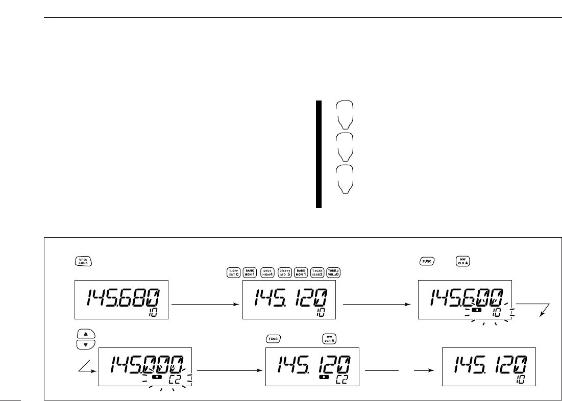
39
6CALL CHANNEL OPERATION
■Programming a call channel
Operating frequency, duplex information, subaudible tone in-
formation (tone encoder or tone squelch ON/OFF and its fre-
quency) can be programmed into the call channel.
qSet the desired frequency in VFO mode.
➥Push [V/MHz•SCAN] to select VFO mode.
➥Set the frequency using [DIAL].
➥Set other data as desired.
wPush [S.MW•MW] momentarily.
eRotate [DIAL] to select the desired call channel.
•“!” indicator and “C1” or “C2” blink.
rPush [S.MW•MW] for 1 sec. to program.
•3 beeps sound and the unit returns to VFO mode automatically.
zSet the desired frequency in VFO mode.
➥Push [VFO/LOCK] to select VFO mode.
➥Set the frequency.
➥Set other data as desired.
xPush [FUNC], then [
CLR
A(MW)] momentarily.
cSelect the call channel via [Y] or [Z].
vPush [FUNC] then [
CLR
A(MW)] for 1 sec. to
program.
•3 beeps sound and the unit returns to VFO mode
automatically.
MR/CALL
MW
[Y]/[Z]
[EXAMPLE]: Programming 145.120 MHz into the call channel 2 via the microphone.
Set the frequency.
Push to select VFO mode. Push , then .
Push , then push for 1 sec.
➠
Push until “C2” appears.
Beep
Beep
Beep
“
“
“
“
“
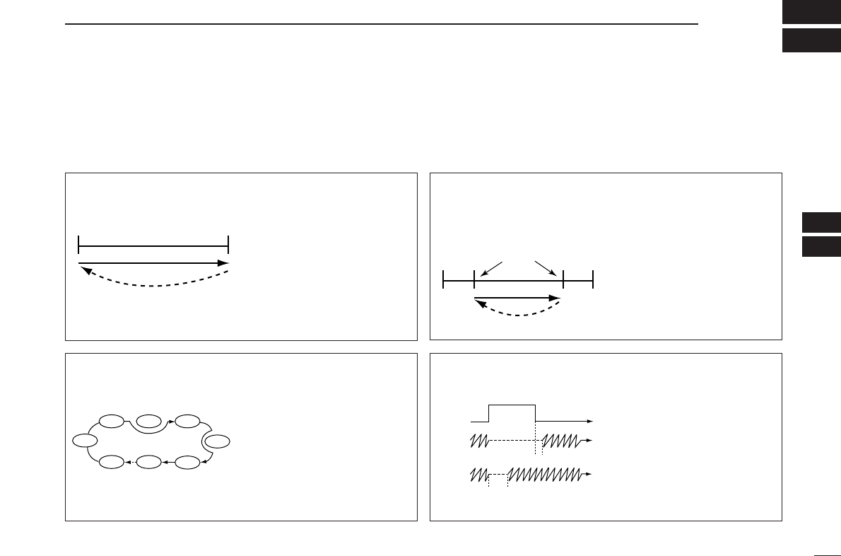
40
7
SCAN OPERATION
6
7
■Scan types
Scanning searches for signals automatically and makes it
easier to locate new stations for contact or listening purposes.
There are 3 scan types and 4 resume conditions to suit your
operating needs.
BAND SCAN (p. 41) Repeatedly scans all frequen-
cies over the entire band.
Used as the simplest scan
without any preliminary set-
tings necessary.
Band
edge Band
edge
Scan
Jump
PROGRAMMED SCAN
(p. 41)
Repeatedly scans between
two user-programmed fre-
quencies. Used for checking
for frequencies within a speci-
fied range such as repeater
output frequencies, etc.
5 pairs of scan edges are
available and scans 1A–1B
(P1), 2A–2B (P2), 3A–3B (P3),
4A–4B (P4), 5A–5B (P5).
Band
edge Band
edge
Scan edges
Scan
Jump
1A
2A
3A
4A
5A
1B
2B
3B
4B
5B
Start End
MEMORY SCAN (p. 41) Repeatedly scans memory
channels except those set as
skip channels. Used for often-
called channels and for by-
passing normally busy
channels such as repeater
frequencies.
SKIP
SKIP
M 1 M 5
M 2 M 3 M 4
M 6
M 500
M 7
SCAN RESUME
CONDITION (p. 45)
4 resume conditions are avail-
able: 3 timer scans and pause
scan. When receiving a sig-
nal, pause scan pauses until
the signal disappears; timer
scans pause for 5, 10 or
15 sec.
Pause
scan
Receiving
a signal
Timer
scan
Pausing
2 sec.
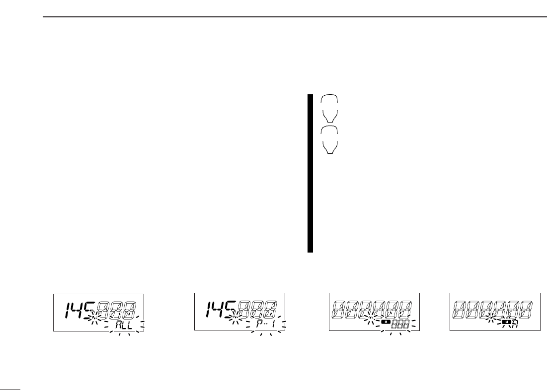
41
7SCAN OPERATION
■Scan start/stop
DPreparation
Scan resume condition (p. 45); program the scan edges
(pgs. 42, 43); program 2 or more memory channels (pgs. 27,
28); set skip settings (p. 44), if desired.
DOperation
qSelect VFO mode for full/programmed scan with
[V/MHz•SCAN]; or memory mode for memory scan with
[M/CALL•PRIO].
•Select the desired bank for bank scan.
wSet the squelch to the point where noise is just muted.
ePush [V/MHz•SCAN] for 1 sec. to start the scan.
•To change the scanning direction, rotate [DIAL].
•The memory channel readout blinks the scan type as follows:
rPush
[SET•LOCK]
to switch full and programmed scan
(P1, P2, P3, P4 and P5), if VFO is selected in step q.
tTo stop the scan, push [V/MHz•SCAN].
zPush [VFO/LOCK] to select VFO mode for
full/programmed scan; push [MR/CALL] to select
memory mode for memory scan.
•Push [FUNC] then [
MONI
1(BANK)] to select a bank
for bank scan.
xPush [
SQL
YD(MUTE)] or [
SQL
Z#(16KEY-L)] to
set the squelch to the point where noise is just
muted.
cPush [
SCAN
2(T-SCAN)] to start the scan.
•Push [Y] or [Z] for 1 sec. also starts the scan.
vPush [
SET
B(D-OFF)] to switch full and pro-
grammed scan (P1, P2, P3, P4 and P5), if VFO
is selected in step z.
bTo stop the scan push [
SCAN
2(T-SCAN)] or
[
CLR
A(MW)].
SCAN
2
SET
B
• During full scan • During programmed scan • During memory scan • During bank scan
Indicates scan edge channels.
• P1 stands for 1A/1B
• P1 to P5 are available when they
are programmed, and switches
with [SET•LOCK].
Indicates bank initial.Push [SET•LOCK] to select
“ALL” (full) or programmed
scan (P1, P2, P3, P4 and P5)
in sequence.
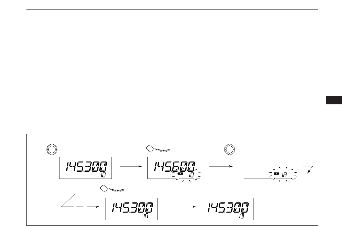
42
7
SCAN OPERATION
7
■Scan edges programming
Scan edges can be programmed in the same manner as
memory channels. Scan edges are programmed into scan
edges, 1A/1B to 5A/5B, in memory channels.
qSet the edge frequency of the desired frequency range in
VFO mode:
➥Set the frequency using [DIAL].
➥Set other data (e.g. repeater settings, etc.) if desired.
wPush [S.MW•MW].
•“!” indicator and channel number blink.
eRotate [DIAL] to select one of scan edge channel, 1A, 2A,
3A, 4A or 5A.
rPush [S.MW•MW] for 1 sec. to program.
•3 beeps sound and VFO is automatically selected.
•Scan edge 1B, 2B, 3B, 4B or 5B is automatically selected when
continuing to push [S.MW•MW] after programming.
tTo program a frequency for the other pair of scan edges,
1B, 2B, 3B, 4B or 5B, repeat steps qto r.
•If the same frequency is programmed into a pair of scan edges,
programmed scan will not function.
[EXAMPLE]: Programming 145.300 MHz into scan edges 1A.
Push
Rotate for setting frequency, etc. Rotate
Push for 1 sec. and continue to push
➠
Beep
Beep
Beep
“
Beep
“
“
“
“
“
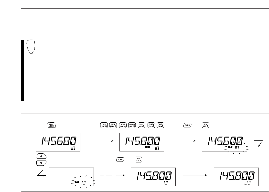
43
7SCAN OPERATION
DProgramming scan edges via microphone
zSet the desired frequency in VFO mode.
➥Push [VFO/LOCK] to select VFO mode.
➥Set the frequency via the keypad or [Y]/[Z].
xPush [FUNC] then [
CLR
A(MW)] momentarily.
cPush [Y] or [Z] to select scan edge channels,
1A, 2A, 3A, 4A or 5A.
vPush [FUNC], then push [
CLR
A(MW)] for 1 sec.
to program.
•3 beeps sound and VFO is automatically selected.
•Memory channel number advances to the next scan
edge channel, 1B, 2B, 3B, 4B or 5B when continuing
to push [
CLR
A(MW)] after programming.
bTo program a frequency for the other scan edge channels,
repeat steps zto v.
MW
[EXAMPLE]: Programming 145.800 MHz into scan edge 1B.
Push Push Push then momentarily
Push Push then for 1 sec. and continue to push
➠
Beep
“
Beep
Beep
Beep
“
“
“
“
“
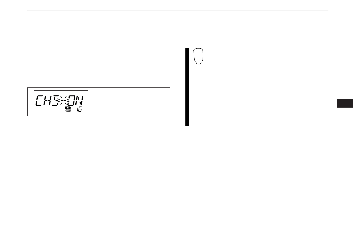
44
7
SCAN OPERATION
7
■Skip channel setting
[
The memory skip function speeds up scanning by checking
only those memory channels not set as skip channels. Set
skip channels as follows.
qSelect a memory channel:
➥Push [M/CALL•PRIO] to select memory mode.
➥Rotate [DIAL] to select the desired channel to be a skip
channel.
wPush
[SET•LOCK]
to enter set mode.
•Rotate [DIAL] to select “SET,” if necessary.
ePush
[SET•LOCK]
or [S.MW•MW] several times until
“CHS” appears as shown above.
rRotate [DIAL] to turn the skip function ON or OFF for the
selected channel.
•“~” appears : The channel is skipped during scan.
(CHS-ON)
•“P~” appears : The channel is skipped during scan and the
programmed frequency is skipped during VFO scan, such as
programmed scan.
(CHS-ON)
•“~” disappears : The channel is scanned during scan.
(CHS-OF)
tPush [MONI•DTMF] to exit set mode.
zSelect a memory channel.
➥Select memory mode by pushing [MR/CALL].
➥Push [Y] or [Z] to select the desired channel
to be a skip channel.
•Direct memory channel selection is also available.
xPush [
SET
B(D-OFF)] to enter set mode.
•Push [Y] or [Z] to select “SET,” if necessary.
cPush [
SET
B(D-OFF)] or [
ENT
C(T-OFF)] several
times until “CHS” appears as shown at left.
vPush [Y] or [Z] to set or cancel the skip setting.
•See item rat left for skip indicator details.
bPush [
CLR
A(MW)] to exit set mode.
SET
B
The display shows that mem-
ory channel 1 is set as a skip
channel.
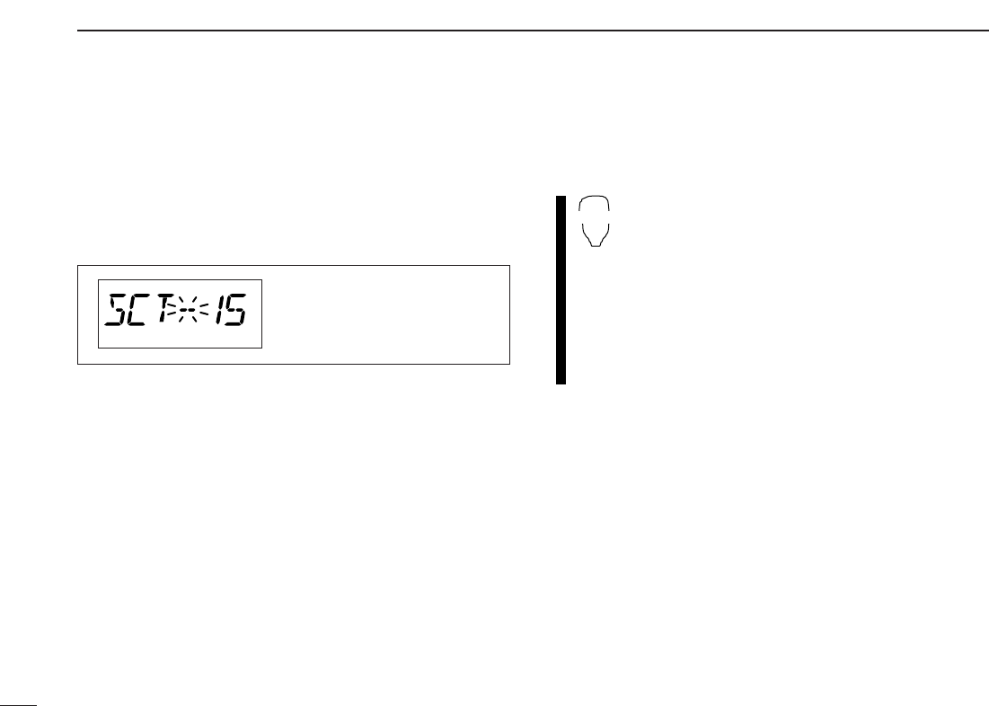
45
7SCAN OPERATION
■Scan resume condition
[
The scan resume condition can be selected as timer or pause
scan. The selected resume condition is also used for priority
watch. (p. 47)
qPush
[SET•LOCK]
to enter set mode.
•Rotate [DIAL] to select “SET,” if necessary.
wPush
[SET•LOCK]
or [S.MW•MW] several times until
“SCT” or “SCP” appears as shown above.
•When “d” is displayed in place of the 100 MHz digit, cancel the
DTMF memory encoder in advance. (p. 50)
eRotate [DIAL] to set the desired timer:
•“SCT-15” : Scan pauses 15 sec. while receiving a signal.
•“SCT-10” : Scan pauses 10 sec. while receiving a signal.
•“SCT-5” : Scan pauses 5 sec. while receiving a signal.
•“SCP-2” : Scan pauses until the signal disappears and then
resumes 2 sec. later.
rPush [MONI•DTMF] to exit set mode.
zPush [BAND] to select the desired band.
xPush [
SET
B(D-OFF)] to enter set mode.
•Push [Y] or [Z] to select “SET,” if necessary.
cPush [
SET
B(D-OFF)] or [
ENT
C(T-OFF)] several
times until “SCT” or “SCP” appears as shown at
left.
vPush [Y] or [Z] to select the scan resume condi-
tion.
•See item eat left for scan resume condition details.
bPush [
CLR
A(MW)] to exit set mode.
SET
B
The display shows that the
scan will resume 15 sec. after
it stops.

46
8
PRIORITY WATCH
7
8
■Priority watch types
Priority watch checks for signals on a VFO frequency every
5sec. while operating in memory mode. The transceiver has
3 priority watch types to suit your needs. You can also trans-
mit on the VFO frequency while the priority watch operates.
The watch resumes according to the selected scan resume
condition. See previous page for details.
☞NOTES:
➧If the pocket beep function is activated, the transceiver
automatically selects the tone squelch function when pri-
ority watch starts.
MEMORY CHANNEL WATCH
While operating on a VFO fre-
quency, priority watch checks for
a signal on the selected memory
channel every 5 sec.
MEMORY SCAN WATCH
While operating on a VFO fre-
quency, priority watch checks for
signals on each memory chan-
nel in sequence.
•The memory skip function is useful
to speed up the scan.
CALL CHANNEL WATCH
While operating on a VFO fre-
quency, priority watch checks for
signals on the call channel every
5sec.
5 sec.
VFO
frequency
50 msec.
Memory
channel
5 sec. 50 msec.
VFO
frequency
SKIP
Mch 1
Mch 2
Mch 3
Mch 199
5 sec.
VFO
frequency
50 msec.
Call
channel