ICOM orporated 278800 VHF/UHF Digital Transceiver User Manual ID 800H FCC
ICOM Incorporated VHF/UHF Digital Transceiver ID 800H FCC
Contents
- 1. Users Manual Part 1
- 2. Users Manual Part 2
Users Manual Part 2

47
8PRIORITY WATCH
■Priority watch operation
qSelect VFO mode; then, set an operating frequency.
wSet the watching channel(s).
For memory channel watch:
Select the desired memory channel.
For memory scan watch:
Select memory mode; then, push [V/MHz•SCAN] for 1 sec.
to start memory scan.
For call channel watch:
Select the desired call channel by pushing [M/CALL•PRIO]
once or twice, then push [BAND].
ePush [M/CALL•PRIO] for 1 sec. to start the watch.
•The transceiver checks the memory or call channel every 5 sec.
•The watch resumes according to the selected scan resume con-
dition. (p. 45)
•While the watch is pausing, pushing [M/CALL•PRIO] resumes
the watch manually.
rPush [M/CALL•PRIO] for 1 sec. to stop the watch.
zSelect VFO mode; then, set the desired fre-
quency.
xSet the watching channel(s).
For memory channel watch:
Push [MR/CALL] then [Y] or [Z] to select the de-
sired memory channel.
For memory scan watch:
Push [MR/CALL], then push [
SCAN
2] to start the
memory scan.
For call channel watch:
Push [MR/CALL] for 1 sec. then push [BAND] to
select the call channel.
cPush [
PRIO
3(PTT-M)] to start the watch.
•The transceiver checks the memory or call channel
every 5 sec.
•The watch resumes according to the selected scan re-
sume condition. (p. 45)
•To resume the watch manually when paused, push
[
PRIO
3(PTT-M)] or [
CLR
A(MW)].
vTo stop the watch, push [
CLR
A(MW)] once (or
twice while watch is paused).
PRIO
3
48
9
DTMF MEMORY ENCODER
8
9
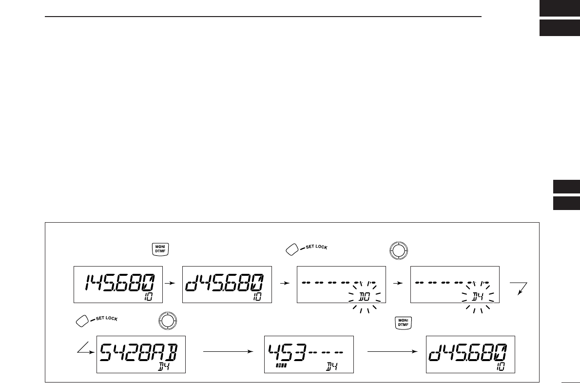
■Programming a DTMF code
DTMF tones are used for autopatching, controlling other
equipment, etc. The transceiver has 16 DTMF memory chan-
nels (D0–DF) for storage of often-used DTMF codes of up to
24 digits.
qPush [MONI•DTMF] for 1 sec. to turn the DTMF encoder
ON.
•“d” appears in place of 100 MHz digit.
wPush
[SET•LOCK]
to enter the DTMF memory program-
ming condition.
•The DTMF memory channel indication blinks.
eRotate [DIAL] to select the desired DTMF memory chan-
nel.
rPush
[SET•LOCK].
•The first digit blinks.
tRotate [DIAL] to select the desired code.
yPush
[SET•LOCK] to select the next digit.
•Pushing [S.MW•MW] moves the cursor backward.
uRepeat the steps tand yto set the desired DTMF tone
sequence.
•The S/RF indicator shows the digit group. The indication in-
creases every 6 digits.
iPush [MONI•DTMF]
to exit DTMF memory programming
condition.
•Return to the previous indication as in step q.
[EXAMPLE]: Programming “5428AB453” into DTMF memory channel “D4.”
Push
Push then rotate Repeat the previous step until
the desired code is entered. Push
RotatePush for 1 sec.
49
9DTMF MEMORY ENCODER
D
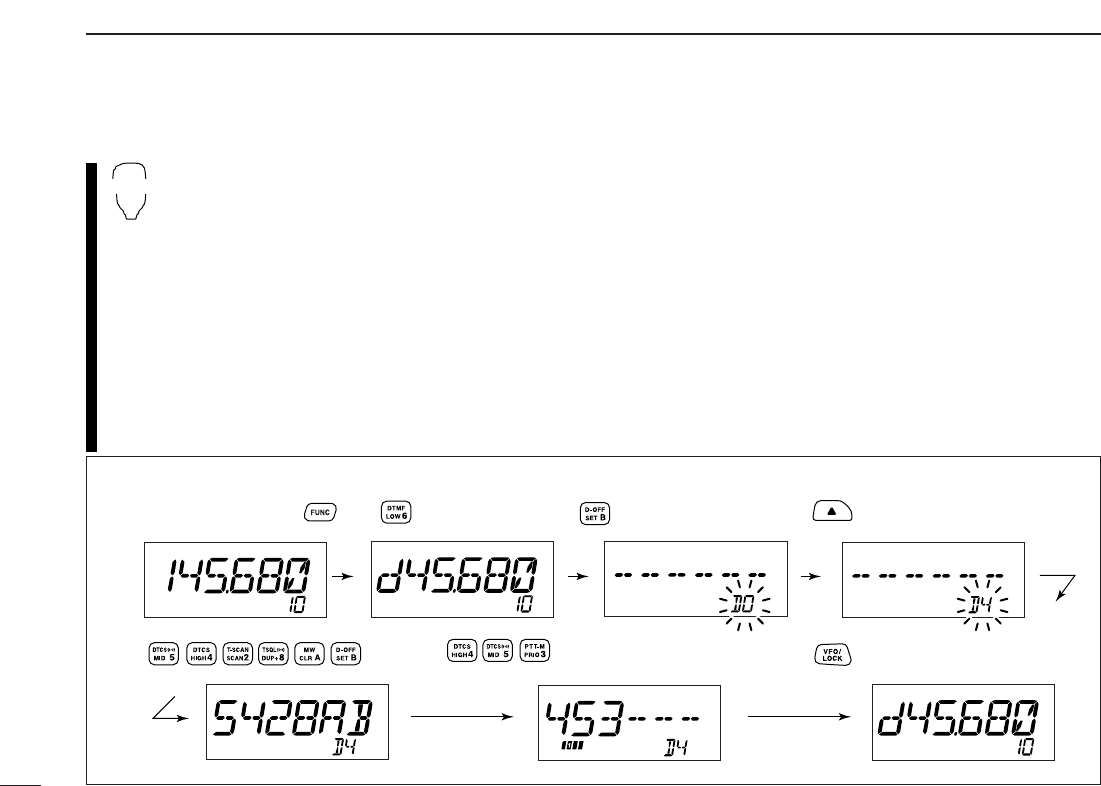
Programming a DTMF code— via microphone
zPush [FUNC] then [
LOW
6(DTMF)] to turn the
DTMF encoder ON.
•
“d” appears in place of 100 MHz digit.
xPush [
SET
B(D-OFF)] to enter the DTMF memory
programming condition.
cPush [Y] or [Z] to select the desired DTMF
memory channel.
vPush the desired digit keys.
•When the first digit is input, previous memory con-
tents are cleared automatically.
•“E” stands for “MM” and “F” stands for “# .”
•Push [Y]/[Z] and repeat this step if you make a mistake.
•The S/RF indicator shows the digit group. The indi-
cation increases every 6 digits.
bPush [VFO/LOCK] to exit the programming condition.
•The [
CLR
A(MW)] key cannot be used to exit. If pushed, code “A”
is input. Reprogram in such a case.
DTMF
[EXAMPLE]: Programming “5428AB453” into DTMF memory channel “D4.”
Push
Push Push
Push
Push then .
50
9
DTMF MEMORY ENCODER
9
■Transmitting a DTMF code
DAutomatic transmission (DTMF memory)
qPush [MONI•DTMF] for 1 sec. to turn the DTMF memory
encoder ON.
• “d” appears in place of 100 MHz digit.
wPush [SET•LOCK] to enter DTMF memory programming
condition.
eRotate [DIAL] to select the desired DTMF memory chan-
nel.
r
Push [PTT] to transmit the selected DTMF memory content.
tPush [MONI•DTMF] for 1 sec. to cancel the DTMF en-
coder.
•When the DTMF encoder is turned ON continuously, each push
of the PTT transmits the previously selected DTMF code.
zPush [FUNC] then [
LOW
6(DTMF)] to turn the
DTMF memory encoder ON.
•
“d” appears in place of 100 MHz digit.
xPush [
SET
B(D-OFF)] to enter the DTMF memory
programming condition.
cPush [Y] or [Z] to select the desired channel.
vPush [PTT] to transmit the selected memory.
•Exit the programming condition automatically.
•Each push of [PTT] transmits the DTMF code.
bPush [FUNC] then [
SET
B(D-OFF)] to cancel the
DTMF memory encoder.
•When the DTMF encoder is turned ON continuously,
each push of the PTT transmits the previously se-
lected DTMF code.
DTransmitting a DTMF memory directly
zPush [FUNC] then [
LOW
6(DTMF)] to turn the
DTMF memory encoder ON.
•
“d” appears in place of 100 MHz digit.
x
Push [DTMF-S] to turn the DTMF memory di-
rect selection ON.
•The function indicator (microphone) lights green.
cPush the desired DTMF channel.
•“0” to “9” and “A” to “D” are available for DTMF
memory channels.
•The selected DTMF code is automatically transmit-
ted without pushing PTT.
NOTE: When no DTMF code programmed
channel number is pushed, it transmits the rela-
tive DTMF code as the manual transmission de-
scribed in the next page.
vPush [DTMF-S] again to deactivate the DTMF
memory direct selection.
bPush [FUNC] then [
SET
B(D-OFF)] to cancel
the DTMF memory encoder.
DTMF-S
DTMF
51
9DTMF MEMORY ENCODER
DManual transmission
zDeactivate the DTMF memory encoder by
pushing [FUNC] then [
SET
B(D-OFF)].
x
Push [DTMF-S] to turn the DTMF direct selec-
tion ON.
•The function indicator (microphone) lights green.
cPush one of “0” to “9” and “A” to “F” keys mo-
mentarily, then push the desired DTMF keys,
0–9 and A to F.
• A: [
CLR
A(MW)] B: [
SET
B(D-OFF)],
C: [
ENT
C(T-OFF)] D: [
SQL
YD(MUTE)],
E: [MM(TONE-1)] F: [
SQL
Z#(16KEY-L)]
•Automatically transmits without pushing PTT.
•The first code, one of “0” to “9” and “A” to “F,” is not
transmitted. DTMF code transmission starts from
the 2nd code.
vPush [DTMF-S] again to deactivate the DTMF
direct selection.
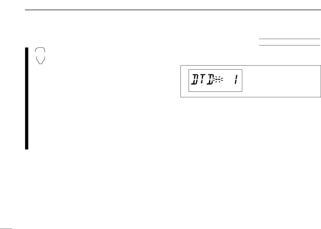
■DTMF speed
The rate at which DTMF memories send individual DTMF
characters can be set to accommodate operating needs.
qPush [PWR] for 1 sec. to turn power OFF.
wWhile pushing
[SET•LOCK],
push [PWR] for 1 sec. to turn
power ON and enter initial set mode.
ePush
[SET•LOCK]
or [S.MW•MW] several times until
“DTD” appears as shown above.
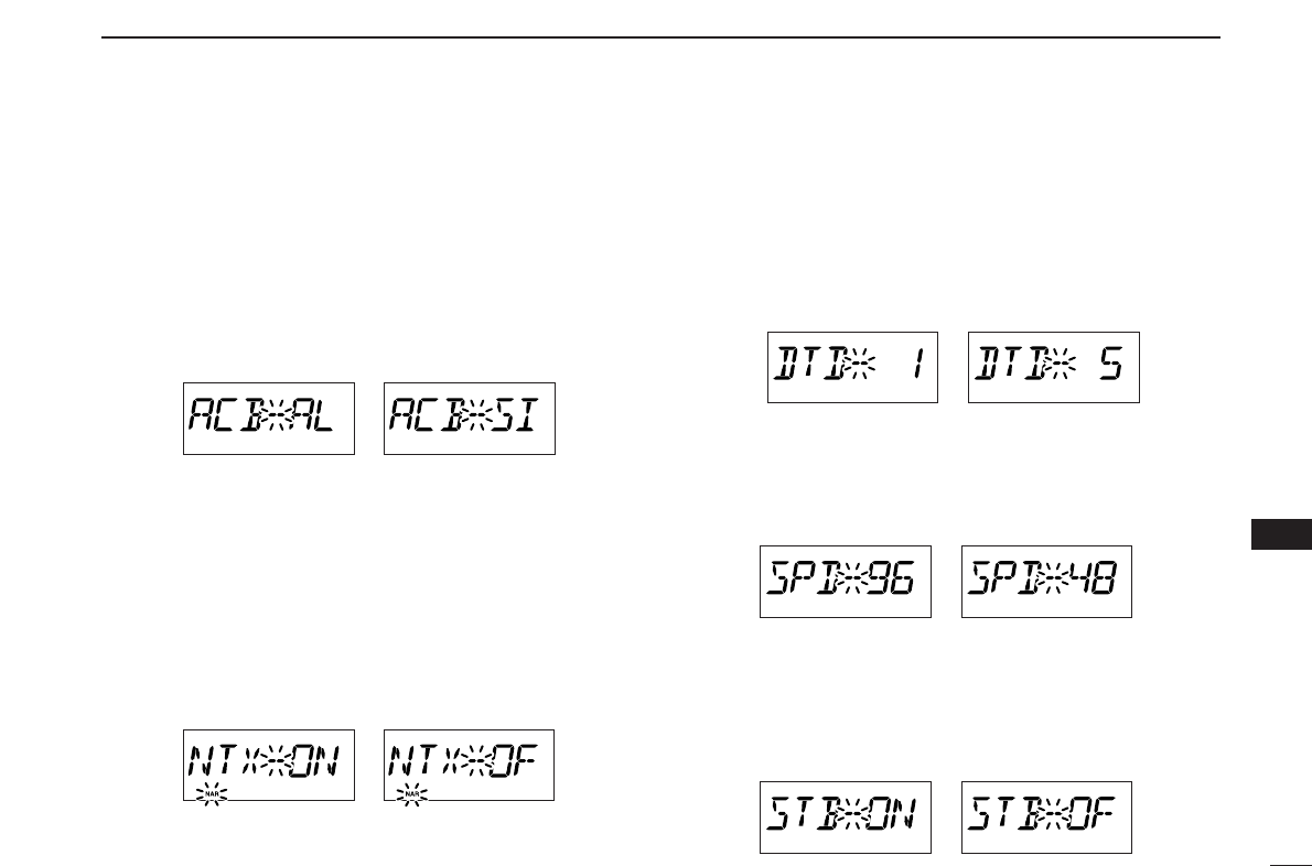
rRotate [DIAL] to select the desired speed as shown in the
table below.
tPush [PWR] to exit initial set mode.
cps=characters/sec
The display shows the fastest
DTMF speed is selected.
USING
INITIAL SET MODE
DTMF-S
52
10
POCKET BEEP AND TONE SQUELCH
9
10
■Pocket beep operation
This function uses subaudible tones for calling and can be
used as a “common pager” to inform you that someone has
called while you were away from the transceiver.
DWaiting for a call from a specific station
qSet the operating frequency.
wPush
[SET•LOCK]
to enter set mode.
•Rotate [DIAL] to select “SET,” if necessary.
ePush
[SET•LOCK]
or [S.MW•MW] several times until “CT”
for tone squelch or “DT” for DTCS squelch appears.
rRotate [DIAL] to select the desired tone squelch frequency.
tWhen operating the pocket beep function with DTCS
squelch, push
[SET•LOCK] once then r
otate [DIAL] to se-
lect the DTCS polarity.
yPush [TONE•T-SCAN] to exit set mode.
uPush [TONE•T-SCAN] several times until “T SQLS” or
“SDTCS” are displayed to turn ON the pocket beep with
tone squelch or DTCS squelch, respectively.
iWhen a signal with the matched tone is received, the
transceiver emits beep tones and blinks “S.”
•Beep tones sound for 30 sec. and “S” blinks. To stop the
beeps and blinking manually, push any key. When the beep
tones are not stopped manually, “S” continues blinking until
[PTT] is pushed (see step o).
oPush [PTT] to answer.
•“S” disappears and cancels the pocket beep function auto-
matically.
!0 Push [TONE•T-SCAN] several times until “T SQL” or
“DTCS” disappears to cancel the tone squelch or DTCS
squelch function.
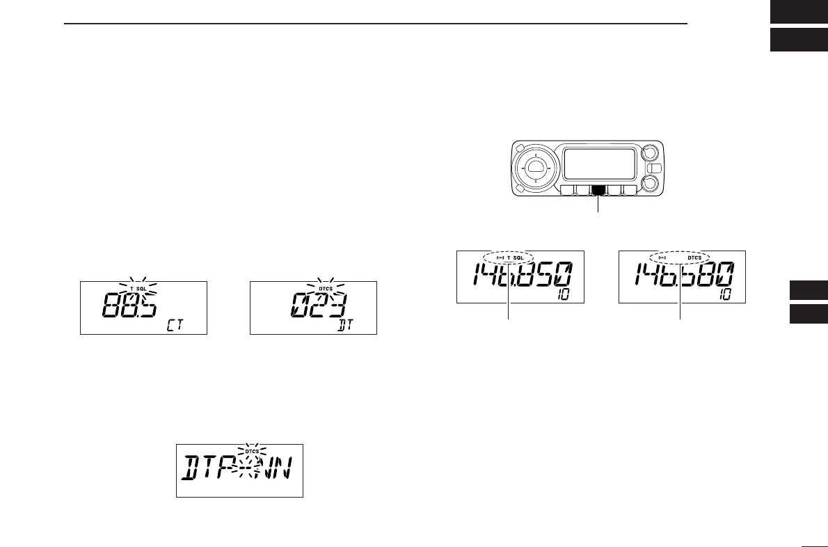
Push [TONE•T-SCAN] several times to select the pocket beep
function with tone squelch or DTCS squelch.
Appears when the pocket beep
with tone squelch is activated.
Appears when the pocket beep
with DTCS squelch is activated.
DTCS polarity setting
Tone squelch frequency setting DTCS code setting
53
10 POCKET BEEP AND TONE SQUELCH
zSet the operating frequency.
xProgram the CTCSS tone frequency or DTCS
code in set mode.
➥Push [
SET
B(D-OFF)] to enter set mode.
•Push [Y] or [Z] to select “SET,” if necessary.
➥Push [
SET
B(D-OFF)] or [
ENT
C(T-OFF)]
several times until “CT” for tone squelch or
“DT” for DTCS squelch appears.
•“TSQL” blinks when tone squelch (“CT”), or
“DTCS” blinks when DTCS squelch (“DT”) is
selected.
➥Push [Y]/[Z] to select the desired tone fre-
quency or DTCS code.
➥Push [
SET
B(D-OFF)] to select “DTP” then
push [Y]/[Z] to select the DTCS polarity.
➥Push [
CLR
A(MW)] to exit set mode.
cPush [FUNC] then push [
DUP
+8(TSQLS)]
or [
MID
5(DTCSS)] to turn ON the pocket
beep with tone squelch or DTCS squelch, re-
spectively.
vWhen a signal with the matched tone is re-
ceived, the transceiver emits beep tones for
30 sec. and blinks “S.”
bPush [PTT] to answer or push [
CLR
A(MW)] to
stop the beeps and blinking.
•“S” disappears and cancels the pocket beep
function automatically.
nTo cancel the tone squelch or DTCS squelch
function, push [FUNC] then [
ENT
C(T-OFF)].
•“TSQL” or “DTCS” disappears
DAvailable tone frequency list
NOTE: The transceiver has 50 tone frequencies and con-
sequently their spacing is narrow compared to units having
38 tones. Therefore, some tone frequencies may receive
interference from adjacent tone frequencies.
To prevent interference from adjacent tone frequencies,
using the frequencies as in the following table, is recom-
mended.
DCalling a waiting station using pocket beep
Asubaudible tone matched with the station’s CTCSS tone fre-
quency or 3-digit DTCS code with polarity is necessary. Use
the tone squelch on the next page or a subaudible tone en-
coder (pgs. 22, 23).
67.0
69.3
71.9
74.4
88.5
91.5
94.8
97.4
114.8
118.8
123.0
127.3
151.4
156.7
162.2
167.9
203.5
210.7
218.1
225.7
77.0
79.7
82.5
85.4
100.0
103.5
107.2
110.9
131.8
136.5
141.3
146.2
173.8
179.9
186.2
192.8
233.6
241.8
250.3
• Recommended tone frequencies
67.0
69.3
71.9
74.4
77.0
79.7
82.5
85.4
88.5
91.5
94.8
97.4
100.0
103.5
107.2
110.9
114.8
118.8
123.0
127.3
131.8
136.5
141.3
146.2
151.4
156.7
159.8
162.2
165.5
167.9
171.3
173.8
177.3
179.9
183.5
186.2
189.9
192.8
196.6
199.5
203.5
206.5
210.7
218.1
225.7
229.1
233.6
241.8
250.3
254.1
TSQLS
DTCSS
54
10
POCKET BEEP AND TONE SQUELCH
10
■Tone/DTCS squelch operation
The tone or DTCS squelch opens only when receiving a sig-
nal with the same pre-programmed subaudible tone or DTCS
code, respectively.
qSet the operating frequency.
wProgram the CTCSS tone frequency or DTCS code in set
mode.
•See p. 52 for programming details.
ePush [TONE•T-SCAN] several times until “T SQL” or
“DTCS” appears in the function display.
rWhen a signal with the matched tone is received, the
squelch opens and the signal can be heard.
•When the received signal includes an unmatched tone, the
squelch does not open. However, the S/RF indicator shows the
received signal strength.
•To open the squelch manually, push [MONI•DTMF].
tOperate the transceiver in the normal way (push [PTT] to
transmit; release [PTT] to receive).
yTo cancel the tone squelch, push [TONE•T-SCAN] several
times until “T SQL” or “DTCS” disappears.
zSet the operating frequency.
xProgram the CTCSS tone frequency or DTCS
code in set mode.
•See p. 52 for programming details.
c
Push [FUNC] then [
SIMP
9(TSQL)] or [
HIGH
4(DTCS)]
to turn the tone squelch or DTCS squelch ON.
vWhen a signal with the matched tone is re-
ceived, the squelch opens and the signal can be
heard.
•When the received signal includes an unmatched
tone, the squelch does not open. However, the S/RF
indicator shows the received signal strength.
•To open the squelch manually, push [
MONI
1(BANK)].
bOperate the transceiver in the normal way (push
[PTT] to transmit; release [PTT] to receive).
nTo cancel the tone squelch, push [FUNC] then
[
ENT
C(T-OFF)].
•“TSQL” or “DTCS” disappears.
TSQL
DTCS
55
10 POCKET BEEP AND TONE SQUELCH
■Tone scan
By monitoring a signal that is being operated with pocket
beep, tone or DTCS squelch function, you can determine the
tone frequency or DTCS code necessary to open a squelch.
qSet the desired operating frequency or memory channel to
be checked for a tone frequency or code.
wPush [TONE•T-SCAN] several times to select the tone
type, tone squelch or DTCS, to be scanned.
•Either “T SQL” or “DTCS” appears
ePush [TONE•T-SCAN] for 1 sec. to start the tone scan.
•To change the scanning direction, rotate [DIAL].
rWhen the CTCSS tone frequency or 3-digit DTCS code is
matched, the squelch opens and the tone frequency is
temporarily programmed into the selected condition such
as memory or call channel.
•The tone scan pauses when a CTCSS tone frequency or 3-digit
DTCS code is detected.
•The decoded CTCSS tone frequency or 3-digit DTCS code is
used for the tone encoder or tone encoder/decoder depending
on the selected tone condition or type in step w.
-“TSQL” : CTCSS tone encoder/decoder
-“DTCS” : DTCS tone encoder/decoder
tPush [TONE•T-SCAN] to stop the scan.
zSet the frequency or memory channel to be
checked for a tone frequency.
xSelects the tone type to be scanned.
•Push [FUNC] then push; [
SIMP
9(TSQL)] for tone
squelch; [
HIGH
4(DTCS)] for DTCS squelch.
cPush [FUNC] then [
SCAN
2(T-SCAN)] to start
the tone scan.
vWhen the tone frequency is matched, the
squelch opens and the tone frequency is pro-
grammed into the selected mode such as
memory or call channel.
bPush [
CLR
A(MW)] to stop the scan.
☞NOTE: The decoded tone frequency is programmed tem-
porarily when a memory or call channel is selected. How-
ever, this will be cleared when the memory/call channel is
re-selected.
T-SCAN
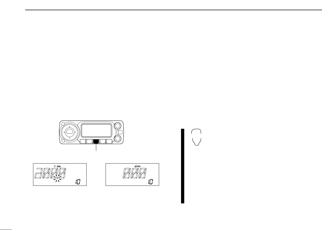
During CTCSS frequency scan During DTCS code scan
Push [TONE•T-SCAN] for 1 sec. to start tone scan.
56
11
OTHER FUNCTIONS
10
11
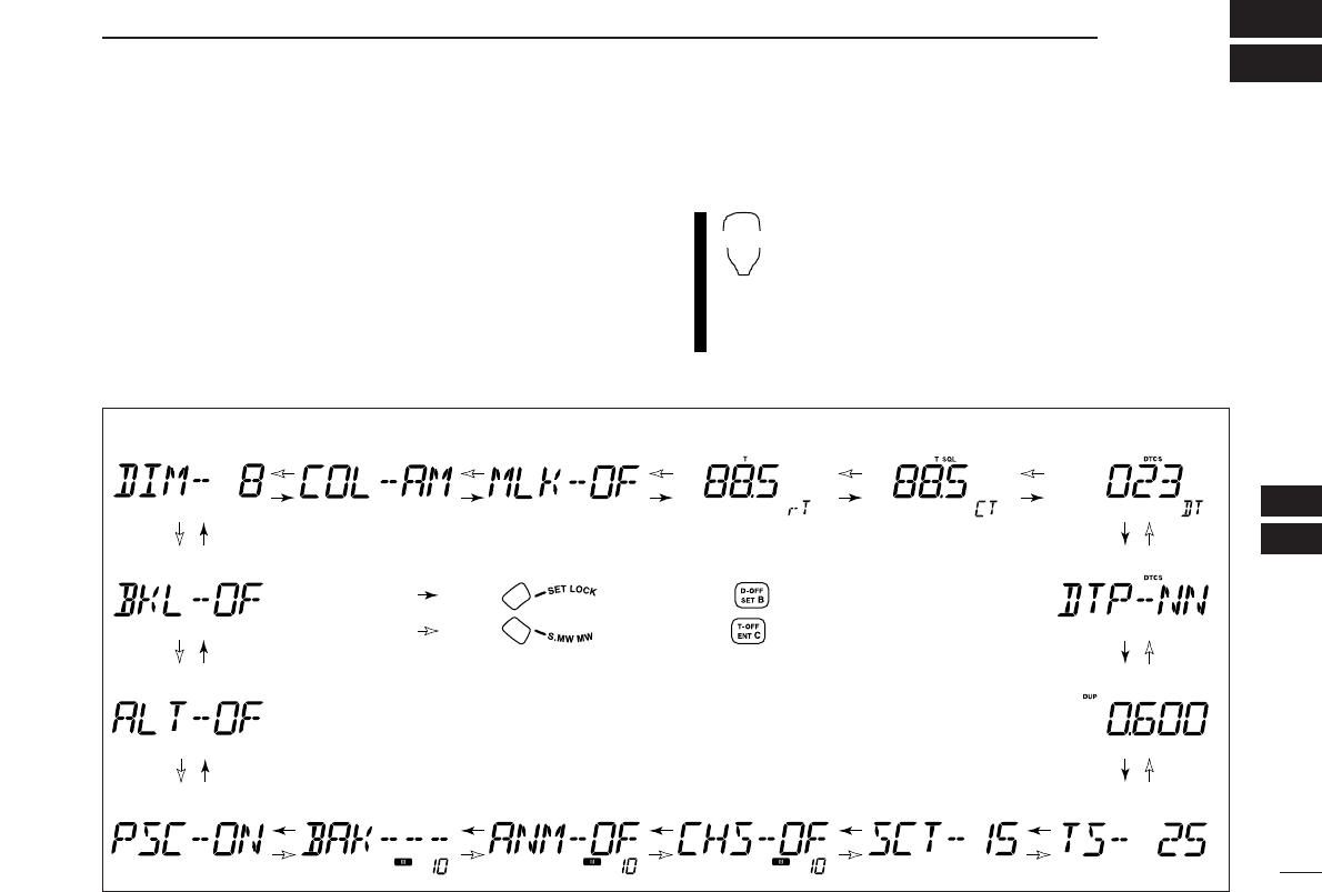
■Set mode
•Set mode operation
qPush
[SET•LOCK]
to enter the set mode.
•Rotate [DIAL] to select “SET,” if necessary.
wPush
[SET•LOCK]
or [S.MW•MW] to select the desired
item.
eRotate [DIAL] to select the condition or value.
rPush
[MONI•DTMF]
to exit set mode.
•Set mode items
zPush [
SET
B(D-OFF)] to enter set mode.
•Push [Y] or [Z] to select “SET,” if necessary.
xPush [
SET
B(D-OFF)] or [
ENT
C(T-OFF)] to select
the desired item.
cPush [Y] or [Z] to select the condition or value.
vPush [
CLR
A(MW)] to exit set mode.
SET
B
*Available for USA version only.
†Appears when accessing set mode from VFO mode only.
‡Appears when accessing set mode from memory mode only.
: Push (front panel); or (microphone)
: Push (front panel); or (microphone)
• Weather alert*
• Display dimmer • Display color • Repeater tone
frequency
• Tone squelch
frequency • DTCS code
• DTCS polarity
• Offset frequency
• Tuning step
• Scan resume timer
• Channel skip setting‡
• Bank link function‡
• Mic lock function
• Program skip† • Bank setting‡ • Memory name‡
57
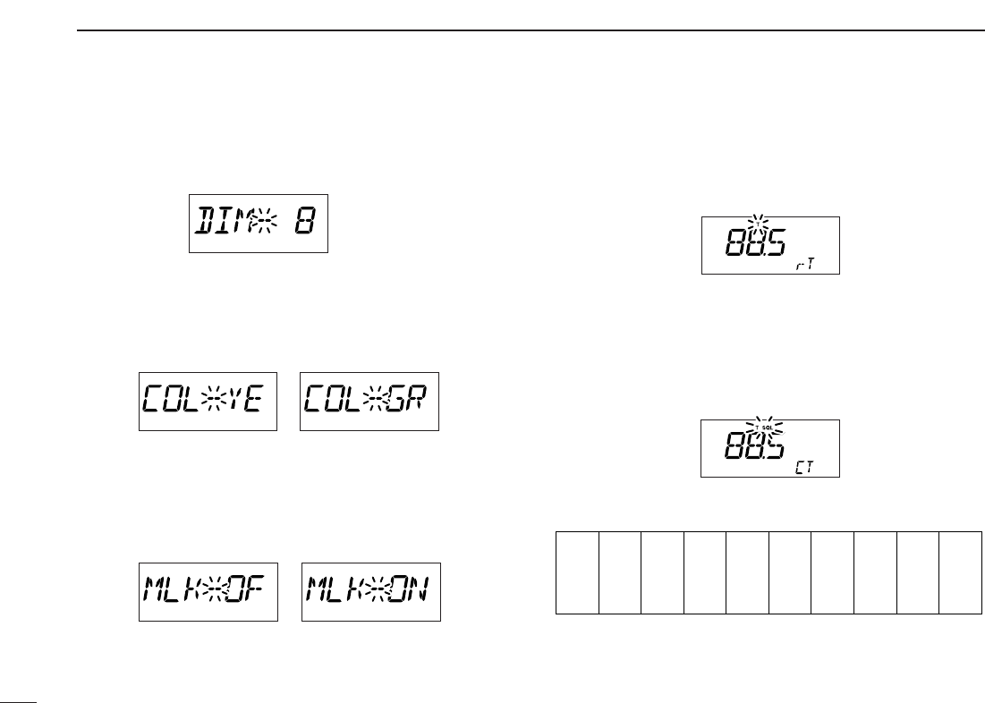
11 OTHER FUNCTIONS
DDDisplay dimmer
Adjust to suit lighting conditions.
The levels 1 (dark) to 8 (bright: default) are available.
DDDisplay color
The display color can be set to amber (default), yellow or
green.
DDMic lock function
Sets the supplied HM-133’s (optional for some versions) key
lock function from ON and OFF (default).
DDRepeater tone
Sets subaudible tone frequency (encoder only) for repeater
operation. Total of 50 tone frequencies (67.0–254.1 Hz) are
available. (default: 88.5 Hz)
DDTone squelch tone
Sets subaudible tone frequency (both encoder and decoder)
for tone squelch operation. Total of 50 tone frequencies
(67.0–254.1 Hz) are available. (default: 88.5 Hz)
•Available subaudible tone frequencies
67.0
69.3
71.9
74.4
77.0
79.7
82.5
85.4
88.5
91.5
94.8
97.4
100.0
103.5
107.2
110.9
114.8
118.8
123.0
127.3
131.8
136.5
141.3
146.2
151.4
156.7
159.8
162.2
165.5
167.9
171.3
173.8
177.3
179.9
183.5
186.2
189.9
192.8
196.6
199.5
203.5
206.5
210.7
218.1
225.7
229.1
233.6
241.8
250.3
254.1
• Yellow setting • Green setting
58
11
OTHER FUNCTIONS
11
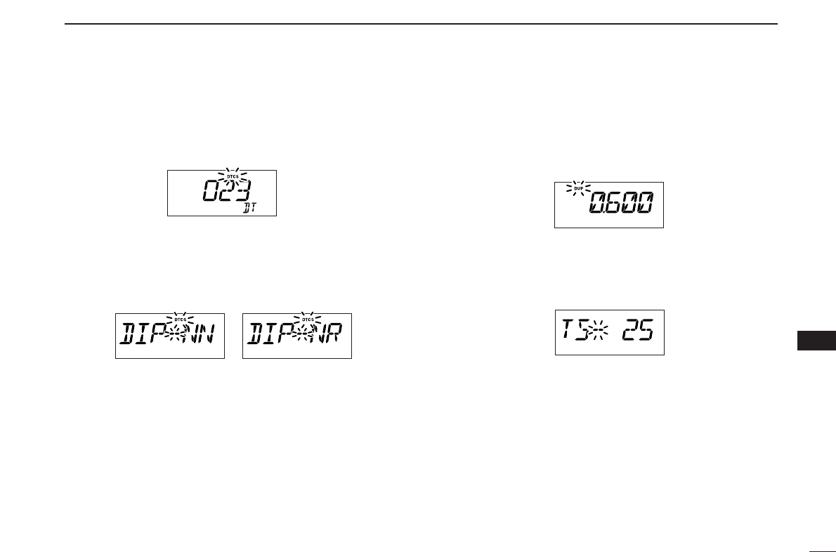
DDDTCS code
Sets DTCS code (both encoder and decoder) for DTCS
squelch operation. Total of 104 codes are available.
(default: 023)
DDDTCS polarity
Sets DTCS polarities for transmission and reception from
“NN,” “NR,” “RN” and “RR.” (default: NN)
DDOffset frequency
Sets the duplex offset frequency within 0 to 20 MHz range.
During duplex (repeater) operation, transmit frequency shifts
the set frequency. (default value may differ depending on operating
frequency band and versions)
DDTuning step
Selects tuning step from 5, 10, 12.5, 15, 20, 25, 30, 50, 100
and 200 kHz for [DIAL] or [Y]/[Z] operation. (default value may
differ depending on operating frequency band and versions)
• Transmit: normal
Receive: normal
(default)
• Transmit: normal
Receive: reverse
59
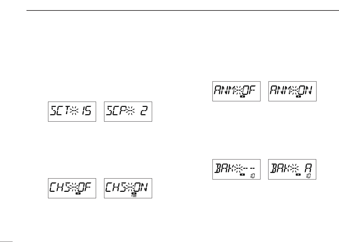
11 OTHER FUNCTIONS
DDScan resume timer
Selects scan resume timer from SCT-15 (default), SCT-10,
SCT-5 and SCP-2.
•SCT-15/10/5 : Scan pauses for 15/10/5 sec., then re-
sumes.
•SCP-2 : Pause on a signal until signal disap-
pears, then resumes 2 sec. after the sig-
nal disappears.
DDChannel skip setting
Sets channel skip setting from ON and OFF for memory skip
scan operation.
This item appears when set mode is accessed from memory
mode only.
DDMemory name setting
Sets memory name setting from ON (appear) and OFF (not
appear; default) for memory name appearance.
This item appears when set mode is accessed from memory
mode only.
DDMemory bank setting
Sets the desired memory bank (A to J and OFF) to assign the
regular memory channels.
This item appears when set mode is accessed from memory
mode only.
• “~” or “P ~” appears
when set to “ON.”
• Default setting
60
11
OTHER FUNCTIONS
11
DDProgram scan skip setting
Sets the program scan skip setting from ON and OFF for
VFO scan operation, such as programmed scan.
This item appears when set mode is accessed from VFO
mode only.
DDWeather alert function
Turns weather alert function ON and OFF.
DDMemory bank link function
Sets the memory bank link function ON and OFF (default).
The link function provides continuous banks scan, that scans
all contents in the selected banks during bank scan.
This item appears when set mode is accessed from memory
mode only.
•Bank link setting
qRotate [DIAL] to select the memory bank link function ON.
wPush
[SET•LOCK]
or [S.MW•MW] to select the desired
bank to be linked.
•BLA: Bank A, BLB: Bank B, BLC: Bank C, BLD: Bank D,
BLE: Bank E, BLF: Bank F, BLG: Bank G, BLH: Bank H,
BLI: Bank I, BLJ: Bank J
eRotate [DIAL] to select “ON” to linking the bank.
rRepeat steps wand eto set the link condition.
U.S.A. version only
61
11 OTHER FUNCTIONS
■Initial set mode
The initial set mode is accessed at power ON and al-
lows you to set seldom-changed settings. In this way,
you can “customize” transceiver operations to suit your
preference and operating style.
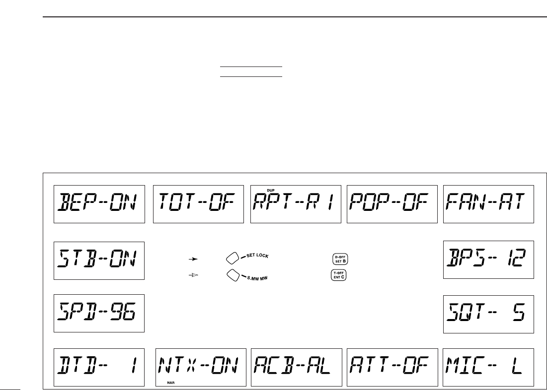
•Initial set mode items
DDEntering initial set mode
qWhile pushing
[SET•LOCK],
push [PWR] for 1 sec. to enter
initial set mode.
wPush
[SET•LOCK]
or [S.MW•MW] to select the desired
item.
eRotate [DIAL] to select the condition or value.
rPush
[PWR]
momentarily to exit initial set mode.
AT
POWER ON
• Active band
• Key-touch beep • Time-out timer • Auto repeater*
• Squelch attenuator • Microphone sensitivity
• Auto power off
• DTMF speed
• Data speed for DV mode
• Stanby beep
• Squelch delay
• Data speed for FM mode
• Cooling fan
• Narrow TX
*Available in the USA version only.
: Push (front panel); or (microphone)
: Push (front panel); or (microphone)
62
11
OTHER FUNCTIONS
11
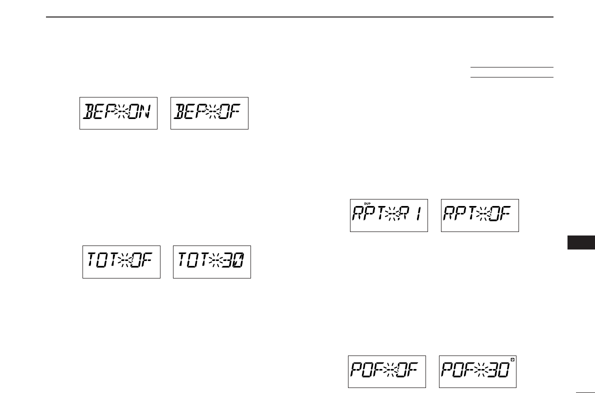
DDKey-touch beep
The key-touch beep can be turned OFF for silent operation.
DDTime-out timer
To prevent accidental prolonged transmission, etc., the trans-
ceiver has a time-out timer. This function cuts a transmission
OFF after 1–30 min. of continuous transmission. This timer
can be cancelled.
•TOT-OF : The time-out timer is turned OFF.
•TOT-3/5/15/30 : The transmission is cut OFF after the
set period elapses.
DDAuto repeater
The auto repeater function automatically turns ON or OFF the
duplex operation with a specified shift direction and tone en-
coder, when the operating frequency falls within or outside of
145.200–145.495, 146.610–146.995, 147.000–147.395,
442.000–444.995, and 447.000–449.995 MHz range. The off-
set and repeater tone frequencies are not changed by the
auto repeater function, reset these frequencies, if necessary.
•OF: The auto repeater function is turned OFF.
•R1: Activates for duplex only.
•R2: Activates for duplex and tone.
DDAuto power OFF
The transceiver can be set to automatically turn OFF after a
specified period with a beep when no key operations are per-
formed.
30 min., 1 hour, 2 hours and OFF can be specified. The spec-
ified period is retained even when the transceiver is turned
OFF by the auto power OFF function. To cancel the function,
select “OF” in this set mode.
U.S.A. version only
63
11 OTHER FUNCTIONS
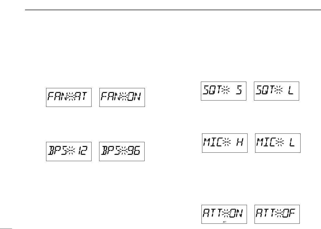
DDCooling fan control
Selects the cooling fan control condition from Auto and ON.
•Auto (AT) : The fan rotates during transmit and for 2 min.
after transmission, or when the internal tem-
perature of the transceiver exceeds the pre-
set value until the temperature drops.
•ON (ON) : The fan continuously rotates.
DDData transmission speed
Selects the data transmission speed for packet operation
from 1200 bps and 9600 bps.
DDSquelch delay
Selects squelch delay from short and long to prevent re-
peated opening and closing of the squelch during reception
of the same signal.
•S : Short squelch delay.
•L : Long squelch delay.
DDMicrophone sensitivity
Selects the microphone sensitivity from high (H) and low (L)
to suits your preference.
DDSquelch attenuator
Turns the squelch attenuator function ON and OFF.
•ON: The squelch attenuator activates when [SQL]
control is set between 12 o’clock and fully
clockwise position.
•OF: The squelch attenuator does not function.
64
11
OTHER FUNCTIONS
11
DDActive band
Selects the frequency selecting condition via [DIAL] or [Y]/[Z]
on the microphone from all (AL) and single (SI).
•All (AL) : The operating frequency can be selected
continuously.
•Single (SI) : The operating frequency can be selected
within the current band. Pushing [BAND] for
1sec. then tuning dial rotation is necessary
for frequency band selection.
DDNarrow TX function
Select the narrow TX function ON and OFF.
•ON: Enables the FM-narrow mode transmission. The
deviation (modulation level) becomes half from
the regular FM transmission can be performed.
• OFF : Inhibits the FM-narrow mode transmission. The
regular FM deviation transmission is performed
(“NAR” indication disappears while transmission)
even when FM-narrow is selected.
DDDTMF speed
The rate at which DTMF memories send individual DTMF
characters can be set to accommodate operating needs.
•1 : 100 msec. interval; 5.0 cps speed
•2 : 200 msec. interval; 2.5 cps speed
•3 : 300 msec. interval; 1.6 cps speed
•5 : 500 msec. interval; 1.0 cps speed
DDData Speed
Select the communication speed between the transceiver and
PC from 4800 baud or 9600 baud. (default: 9600)
DDStandby Beep
Turns the beep emission capability when the communicating
station finishes transmitting or the receive signal disappears.
while in the digital mode operation. (default: OFF)
65
11 OTHER FUNCTIONS
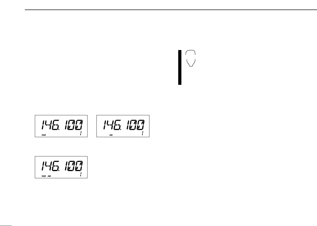
■AM/FM narrow mode
The ID-800H has AM mode reception and FM narrow mode is
available. Typically, AM mode is used for the air band
(118–135.995 MHz).
qSelect the desired frequency band in VFO mode, or the de-
sired memory channel.
wPush
[BAND] for 1 sec. to select AM/FM narrow mode as
desired.
•“NAR” (FM narrow), “AM” and “NAR AM” appears in sequence.
• No indication
stands for FM mode.
zPush [BAND] or [MR/CALL] to select the desired
frequency band or memory channel.
xPush
[BAND] for 1 sec. to select AM/FM narrow
mode as desired.
•“NAR”, “AM” and “NAR AM” appears in sequence.
• No indication
stands for FM mode.
SET
B
• When FM narrow mode
is selected
• When AM mode is selected
• When AM narrow mode is selected
66
11
OTHER FUNCTIONS
11
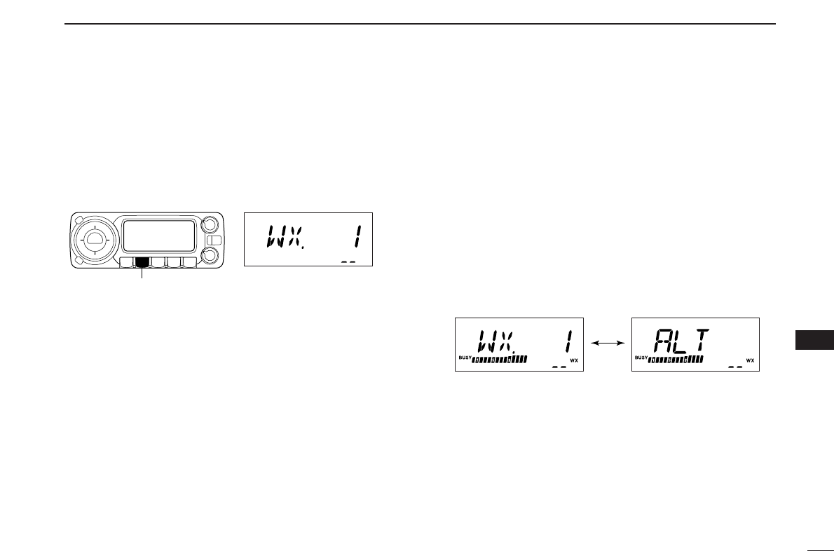
■Weather channel operation
(USA version only)
DDWeather channel selection
qPush [M/CALL•PRIO] several times to select weather
channel group.
wRotate [DIAL] to select the desired weather channel.
ePush [M/CALL•PRIO] to select memory mode, or push
[V/MHz•SCAN] to select VFO mode.
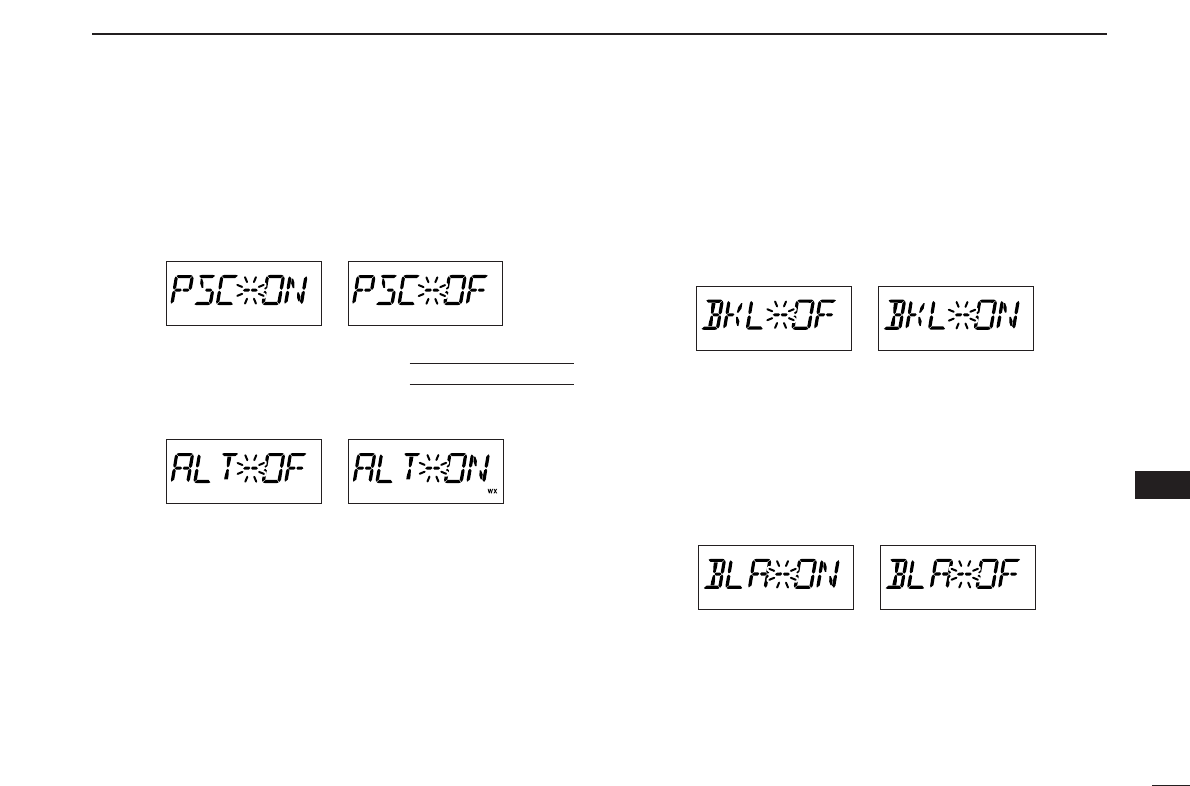
DDWeather alert function
NOAA broadcast stations transmit weather alert tones before
important weather announcements. When the weather alert
function is turned ON, the selected weather channel is moni-
tored each 5 sec. for the announcement. When the alert sig-
nal is detected, the “AL.T” and the WX channel are displayed
alternately and sounds a beep tone until the transceiver is op-
erated. The previously selected (used) weather channel is
checked periodically during standby or while scanning.
qSelect the desired weather channel.
wTurn the weather alert function ON in set mode.
➥Push
[SET•LOCK]
to enter set mode.
➥Push
[SET•LOCK]
or [S.MW•MW] to select the weather
alert item, then rotate [DIAL] to set ON.
➥Push
[MONI•DTMF]
to exit set mode.
eSets the desired stand-by condition.
•Selects VFO, memory or call channel.
•Scan or priority watch operation can also be selected.
rWhen the alert is detected, a beep sounds and the follow-
ing indication will be displayed.
tTurn the weather alert function OFF in set mode.
☞NOTE: While receiving a signal (on a frequency other than
the weather alert ON frequency), the receiving signal or
audio will be interrupted momentarily every 5 sec. (approx.)
in case the alert function is turned ON. This symptom is
caused by the WX alert function. To cancel these symp-
toms, set the weather alert item OFF in set mode.
Shows above indications alternately.
Weather channel group indicaiton
[M/CALL•PRIO]

67
11 OTHER FUNCTIONS
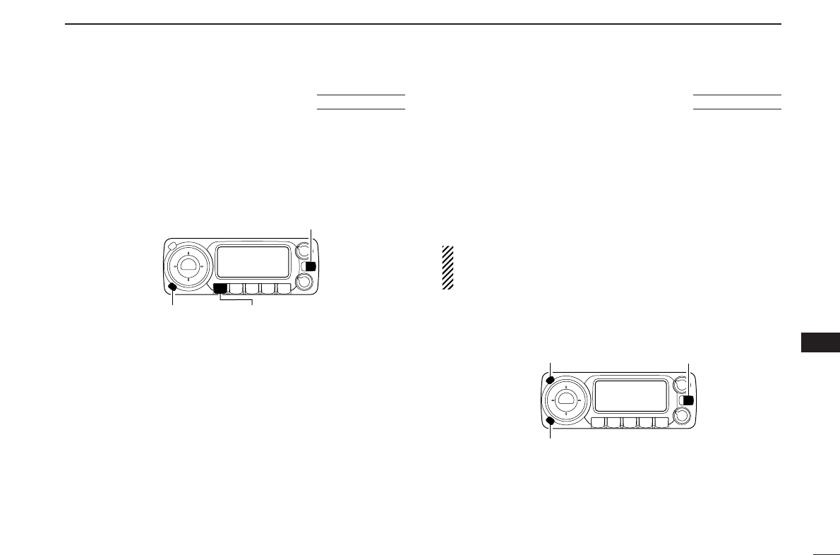
■Microphone keys
The supplied HM-133’s (optional for some versions) [F-1] and
[F-2] keys memorize the transceiver conditions.
The [UP]/[DN] keys of the standard or an optional microphone
(other than the HM-133) can be assigned functions like the
function keys on the transceiver’s front panel.
DD[UP]/[DN] keys on a microphones
(other than HM-133)
The following functions are assigned to [UP]/[DN] keys on the
other microphones (HM-118N/TAN, etc.) when first applying
power.
•Default setting
[UP] : channel up; push and hold to start scan, push again
to stop scan.
[DN] : channel down; push and hold to start scan, push
again to stop scan.
➥Assigning a function
qTurn the power OFF.
wWhile pushing the desired switch on the transceiver and
one of either [UP]/[DN] keys on the microphone, turn the
power ON.
•The function is programmed into the key.
➥Clearing an assignment
qTurn the power OFF.
wWhile pushing the desired [UP] or [DN] key on the micro-
phone, turn the power ON.
DD[F-1]/[F-2] keys on HM-133
The following conditions can be memorized into [F-1] and [F-
2] keys, independently.
•Operating frequency
•Repeater setting (offset direction and frequency, tone ON/OFF
and frequency)
•Tone/DTCS squelch (ON/OFF, frequency/code and polarity)
•Transmit output power selection
•Tuning step
•Operating mode selection (FM/AM)
➥Programming the band condition
Push [F-1]/[F-2] for 1 sec.
•3 beeps sound.
➥Recalling the band condition
Push [F-1]/[F-2] momentarily.
➥Initializing the band condition
Push [FUNC] then push [F-1]/[F-2].
The following conditions are initialized.
•Operating band: 145 MHz band
•Repeater setting (tone frequency: 88.5 Hz, offset
frequency: 600 kHz)
•
Tone/DTCS squelch (ON/OFF: OFF, tone fre-
quency:88.5 Hz, DTCS code: 023 and polarity: NN)
•Transmit output power selection: HIGH
•Tuning step: 5 kHz
•Call channel: 1 CH, memory channel: 1CH
•Operating mode selection: FM
[F-1]/[F-2]
AT
POWER ON
68
11
OTHER FUNCTIONS
11
■Partial reset
If you want to initialize the operating conditions (VFO fre-
quency, VFO settings, set mode contents) without clearing
the memory contents.
➥While pushing [V/MHz•SCAN] and [SET•LOCK], push
[PWR] for 1 sec. to partially reset.
■All reset
The function display may occasionally display erroneous in-
formation (e.g. when first applying power). This may be
caused externally by static electricity or by other factors.
If this problem occurs, turn power OFF. After waiting a few
seconds, turn power ON again. If the problem persists, per-
form the following procedure.
•Partial resetting is also available. See left for details.
IMPORTANT!:
Resetting the transceiver CLEARS all memory information
and initializes all values in the transceiver.
➥While pushing [S.MW•MW] and [SET•LOCK], push [PWR]
for 1 sec. to reset the CPU.
[S.MW•MW]
[SET•LOCK] [PWR]
AT
POWER ON
[S.MW•MW]
[PWR]
[V/MHz•SCAN]
AT
POWER ON
69
11 OTHER FUNCTIONS
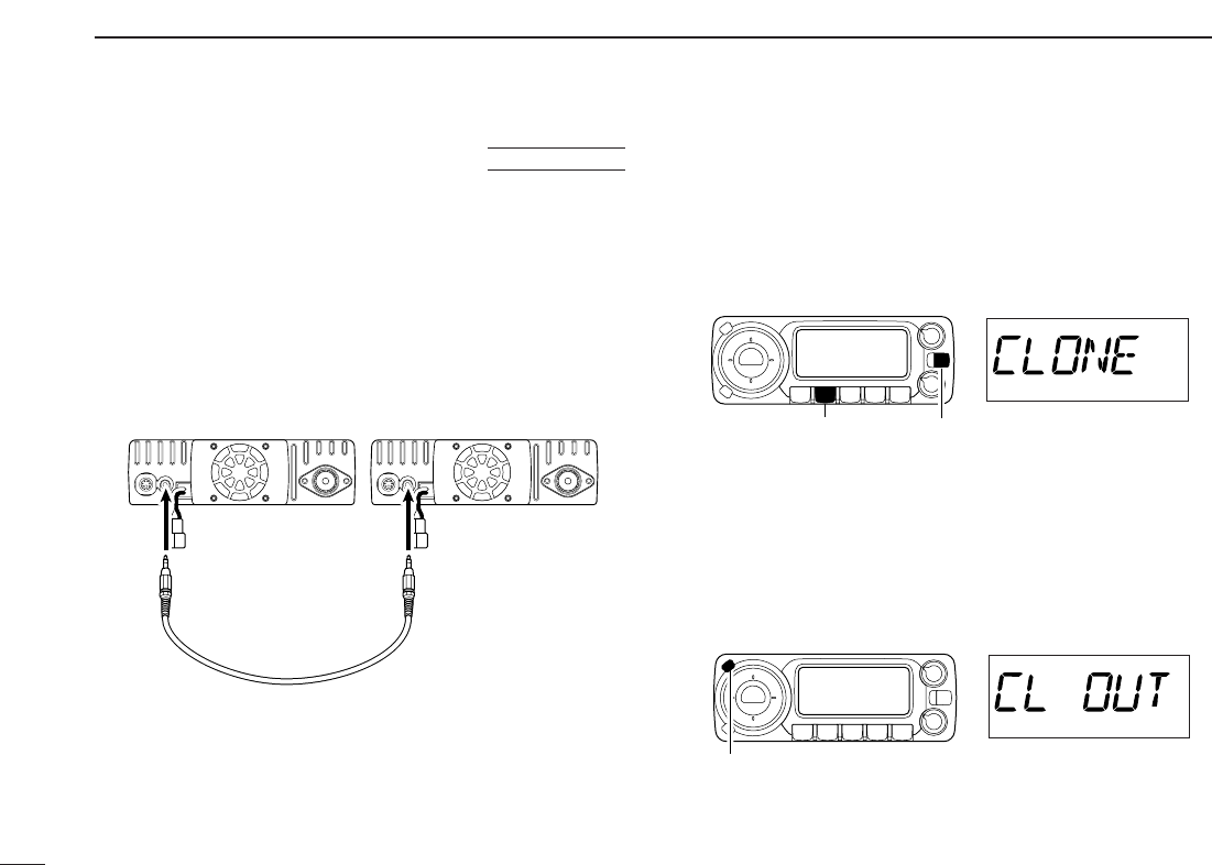
■Data cloning
Cloning allows you to quickly and easily transfer the pro-
grammed contents from one transceiver to another; or data
from a personal computer to a transceiver using the optional
CS-D800
CLONING SOFTWARE
.
DCloning between transceivers
qConnect the OPC-474 cloning cable to [SP] jack of the
master and sub-transceivers.
•The master transceiver is used to send data to the sub-trans-
ceiver.
wWhile pushing [M/CALL•PRIO], turn power ON to enter
cloning mode (master transceiver only— power on only for
sub-transceiver).
•“CLONE” appears and the transceivers enter the clone standby
condition.
ePush [SET•LOCK] on the master transceiver.
•“CL OUT” appears in the master transceiver’s display and the
S/RF indicators show that data is being transferred to the sub-
transceiver.
•“CL IN” appears automatically in the sub-transceiver’s display
and the S/RF indicators show that data is being received from
the master transceiver.
rWhen cloning is finished, turn power OFF, then ON to exit
cloning mode.
Pushing [SET•LOCK] start cloning.
While pushing [M/CALL•PRIO], turn power ON.
[PWR]
[M/CALL•PRIO]
To [SP] To [SP]
AT
POWER ON

70
11
OTHER FUNCTIONS
11
DCloning using a personal computer
Data can be cloned to and from a personal computer (Mi-
crosoft®Windows®98/2000/Me/XP) using the optional CS-208
CLONING SOFTWARE
and the optional cloning cable OPC-478U
(USB type) or OPC-478 (RS-232C type). Consult the CS-208
CLONING SOFTWARE
HELP file for details.
DCloning error
☞NOTE: DO NOT push any key on the sub-transceiver dur-
ing cloning. This will cause a cloning error.
When the display as below appears, a cloning error has oc-
curred.
In such a case, both transceivers automatically return to the
clone standby condition and cloning must be repeated.
71
11 OTHER FUNCTIONS
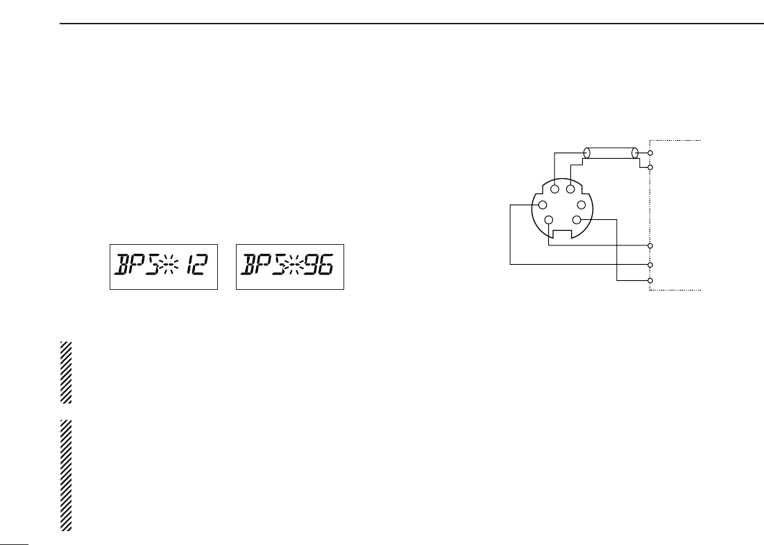
■Packet operation
DData speed
For packet operation, the transceiver can be set to one of two
data speeds: 1200 bps or 9600 bps.
qWhile pushing
[SET•LOCK],
push [PWR] for 1 sec. to enter
initial set mode.
wPush
[SET•LOCK]
or [S.MW•MW] to select the ‘BPS’ item.
eRotate [DIAL] to select the desired data speed.
rPush
[PWR]
to exit initial set mode.
For 1200 bps operation—
•Disconnect the microphone plug from the microphone
connector during data transmission, otherwise the data
signal and voice signal are simultaneously transmitted.
For 9600 bps operation—
•When the transceiver is set for 9600 bps data transmis-
sion in set mode, the microphone signal is automatically
cut. Therefore, it is not necessary to disconnect the mi-
crophone plug from the connector in this case.
•
When pushing [PTT] during data transmission, data trans-
mission is interrupted and voice signals have priority.
D1200 bps packet operation
qConnect the transceiver and a TNC as illustrated below.
wSet the TNC for transmit.
eSet transmit delay on the TNC.
rAdjust the TNC frequency deviation if necessary.
•When using a deviation meter:
Adjust the output of the TNC so that frequency deviation
is in the range ± 3 to ±4 kHz.
•When NOT using a deviation meter:
Areceiver or transceiver is needed to monitor the trans-
mission—compare the received audio output level when
receiving a TNC modulated signal with high level voice
signals using the microphone. Then adjust the TNC mod-
ulated signal to a lower level than the voice modulated
signal.
SQL
PTT
RX AUDIO
GND
TX AUDIO
TNC side
q DATA IN
w GND
e PTT P
t AF OUT
y P SQL

72
11
OTHER FUNCTIONS
11
•Read the instructions supplied with your TNC carefully
before attempting packet operation with the transceiver.
•Pin tAF OUT is for 1200 bps operation only. This pin
cannot be used for 9600 bps operation.
•Over modulation may degrade signal quality. If you find
that many transmissions are failing, re-adjust the modu-
lation level.
73
11 OTHER FUNCTIONS
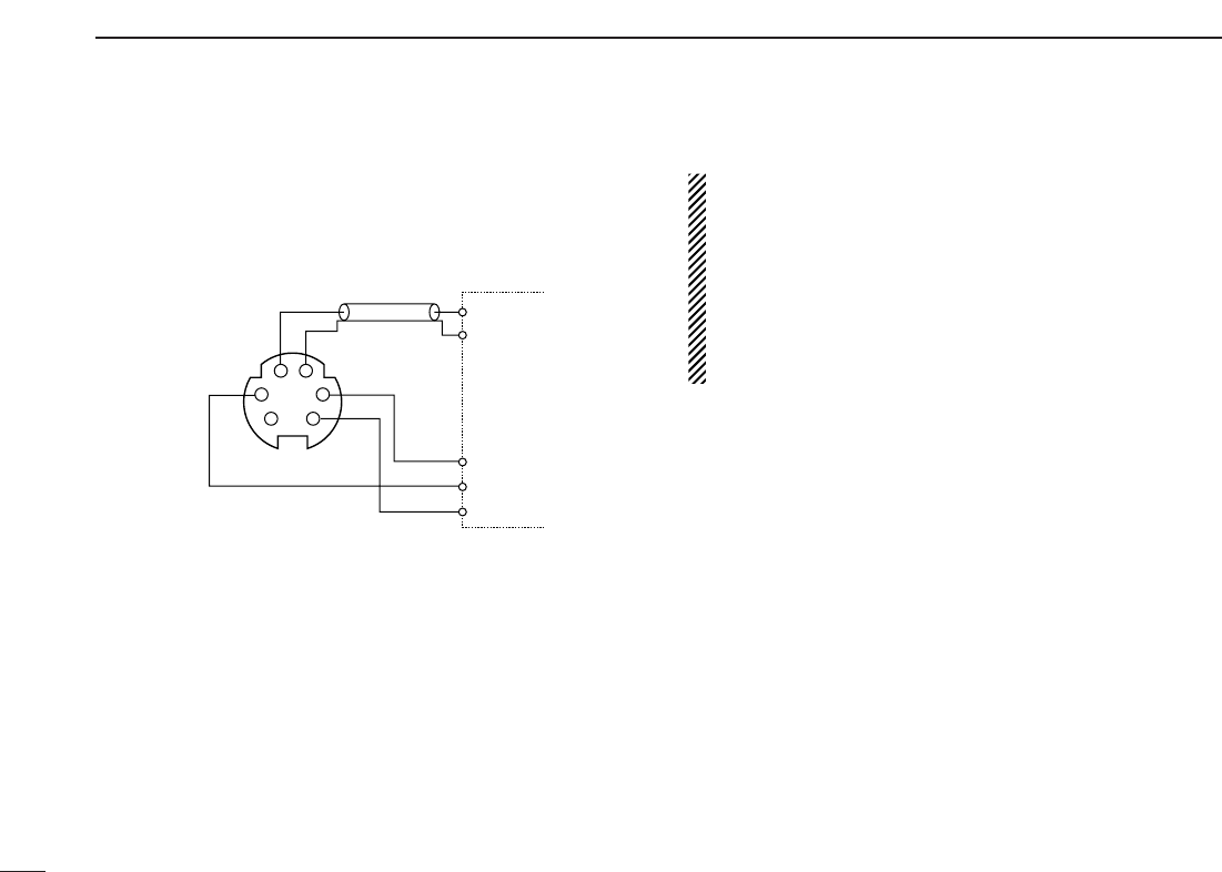
D9600 bps high speed packet operation
The transceiver supports 2 modes of 9600 bps packet opera-
tion: G3RUH and GMSK.
qConnect the transceiver and a TNC as illustrated below.
wG3RUH mode can handle 16 kinds of modulated wave
forms in order to maintain a communication link.
eSet transmit delay on the TNC.
rAdjust the TNC frequency deviation if necessary (see page
at right).
•When using the PTT P terminal for packet operation, no
voice signals are transmitted from the microphone.
•When pushing [PTT] during data transmission, data
transmission is interrupted and the voice signal takes pri-
ority.
•Read the instructions supplied with your TNC carefully
before attempting packet operation with the transceiver.
•Pin rDATA OUT is for 9600 bps operation only. This pin
cannot be used for 1200 bps operation.
TNC side
SQL
PTT
RX AUDIO
GND
TX AUDIO
q DATA IN
w GND
e PTT P r DATA OUT
y P SQL

74
11
OTHER FUNCTIONS
11
DAdjusting the transmit signal output from
the TNC
When setting data transmission speed to 9600 bps, the data
signal coming from the TNC is applied exclusively to the in-
ternal limiter circuitry to automatically maintain band width.
NEVER apply data levels from the TNC of over the accept-
able level below, otherwise the transceiver will not be able to
maintain the band width and may possibly interfere with other
stations.
1. When using a level meter or synchroscope, adjust the
TX audio output level (DATA IN level) from the TNC as
follows.
2 Vp-p (1 Vrms) : recommended level
1 Vp-p–3 Vp-p (0.5–1.5 Vrms) : acceptable level
2. When NOT using a measuring device.
qConnect the transceiver to a TNC.
wEnter a test mode (“CAL,” etc.) on the TNC, then trans-
mit some test data.
eWhen the transceiver fails to transmit the test data or
transmits sporadically (TX indicator doesn’t appear or
flashes):
- Decrease the TNC output level until the transmit indi-
cator lights continuously.
When transmission is not successful even though the
TX indicator lights continuously:
- Increase the TNC output level.
75
DIGITAL MODE OPERATION
12
■Digital mode operation
The ID-800H can be operated for digital voice mode and slow
data operation for both transmit and receive. Also available
for connecting GPS receiver (compatible with an RS-232C
output/NMEA format/4800 bps) and transmit/receive position
data.
■Call sign programming
4 kind of call sign memories are available for your own call
sign “MyCALL,” other station call sign “UrCALL” and nearest
repeater call sign “RPT1 C” and another zone’s repeater call
sign “RPT2 C.” Each call sign memory can be stored up to 6
call signs, and each call sign programmed up to 8 characters.
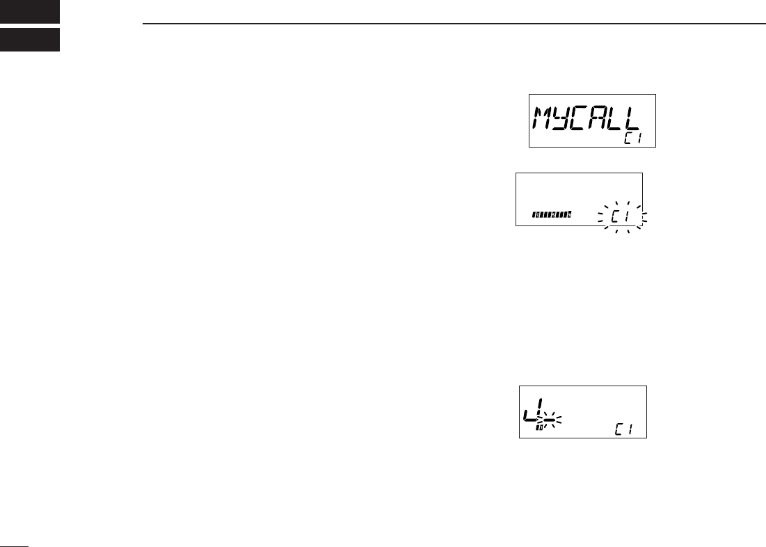
DDYour call sign programming
Your call sign must be programmed for both Digital voice and
slow data communications (including GPS transmission).
qPush [SET•LOCK] to enter call sign set mode.
•Rotate [DIAL] to select “CALLS,” if “SET” or “MESSAG” is dis-
played.
wPush
[SET•LOCK]
or [S.MW•MW] several times to select
“MyCALL,” then push [BAND].
eRotate [DIAL] to select the desired call sign channel.
ePush [BAND] to set into call sign programming condition.
•The 1st digit blinks and channel indication stops blinking.
rRotate [DIAL] to set the desired character or code.
•Push [SET•LOCK] or [S.MW•MW] to move the cursor to right or
left, respectively.
•Push [V/MHz] to cancel and exit the call sign programming.
tPush [SET•LOCK] to select 2nd digit, then rotate [DIAL]
to set the desired character or code.
•2nd digit blinks (1st digit stop blinking).
•Repeat this step for programming your call sign.
yPush [BAND] twice to fix the call sign.
uRotate [DIAL] to select an another channel from “C1” to
“C6.”
iRepeat steps wto yto program your call sign channels.
76
12
DIGITAL MODE OPERATION
1
2
3
4
5
6
7
8
9
10
11
12
13
14
15
16
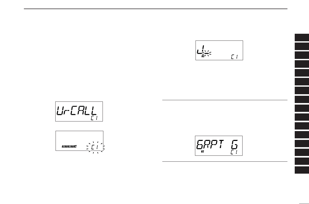
DDStation/Repeater1/2 call sign programming
Station call sign must be programmed for the specified sta-
tion call as well as repeater operation in both Digital voice and
slow data communications.
qPush [SET•LOCK] to enter call sign set mode.
•Rotate [DIAL] to select “CALLS,” if “SET” or “MESSAG” is dis-
played.
wPush
[SET•LOCK]
or [S.MW•MW] several times to select
the call sign item, then push [BAND].
•“UrCALL” appears for station call sign.
•“RPT1 C” or “RPT2 C” appears for repeater call sign.
eRotate [DIAL] to select the desired call sign channel.
ePush [BAND] to set into call sign programming condition.
•The 1st digit blinks and channel indication stops blinking.
rRotate [DIAL] to set the desired character or code.
•Push [SET•LOCK] or [S.MW•MW] to move the cursor to right or
left, respectively.
•Push [V/MHz] to cancel and exit the call sign programming.
tPush [SET•LOCK] to select 2nd digit, then rotate [DIAL]
to set the desired character or code.
•2nd digit blinks (1st digit stop blinking).
•Repeat this step for programming station/repeater call sign.
yPush [BAND] twice to fix the call sign.
uRotate [DIAL] to select an another channel from “C1” to
“C6.”
iRepeat steps wto yto program another station/repeater
call sign channels.
✔
For your information:
Repeater call sign can be programmed gateway connection
capabilities at step rfor connecting to the other Area or
Zone.
•“G” appears or disappears at the 8th digit when each pushing
[M/CALL].
77
12 DIGITAL MODE OPERATION
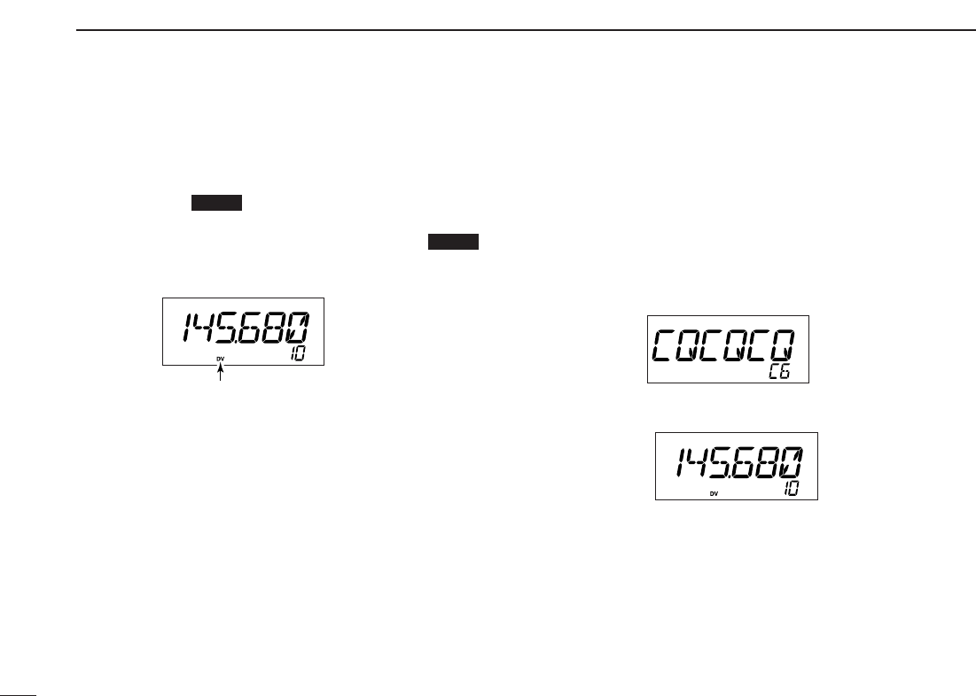
■Digital voice mode operation
qSet the desired frequency in VFO mode. (pgs. 11, 12)
•Select output power, if desired. (p.17)
wPush [BAND ] for 1 sec. to enter the mode selec-
tion condition.
eRotate [DIAL] to select “DV,” then push [BAND ] to
set the digital mode.
•“DV” appears.
r
Push [SET•LOCK] to enter the call sign set mode.
•Rotate [DIAL] to select “CALLS,” if “SET” or “MESSAG” is dis-
played.
t
Push [SET•LOCK] or [S.MW•MW] several times until “My
CALL” apperes.
yRotate [DIAL] to select the desired your call sign channel,
if you have programmed several call signs.
DDWhen sending a CQ
uSelect “CQ” as the call sign.
-Push [SET• LOCK] to select the call sign select mode.
•Rotate [DIAL] to select “CALLS,” if “SET” or “MESSAG” is dis-
played.
-Push [SET•LOCK] or [S.MW•MW] several times until “Ur-
CALL” appears, then push [BAND].
-Rotate [DIAL] to select the desired channel then push
[BAND].
-Push [V/MHz] to edit “CQCQCQ.”
-Push any key below the display to exit call sign set mode.
iPush and hold [PTT] to transmit and speak into the micro-
phone at normal voice level.
•Transmit indicator appears and the RF meter shows the output power.
oRelease [PTT] to return to receive.
•The other station call sign will be received.
•Received call signs can be stored into the received call record
automatically. See page 79 for details.
Appears
MODE
MODE
78
12
DIGITAL MODE OPERATION
1
2
3
4
5
6
7
8
9
10
11
12
13
14
15
16
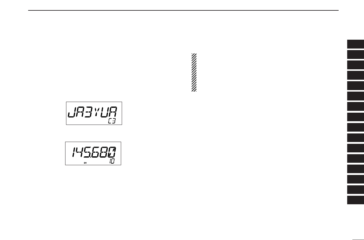
DDWhen calling the desired station
uSelect the desired call sign.
-Push [SET• LOCK] to select the call sign select mode.
•Rotate [DIAL] to select “CALLS,” if “SET” or “MESSAG” is dis-
played.
-Push [SET•LOCK] or [S.MW•MW] several times until “Ur-
CALL” appears, then push [BAND].
-Rotate [DIAL] to select the desired call sign (pre-pro-
grammed), or set the desired call sign. (see p. 76)
-Push any key below the display to exit call sign set mode.
iPush and hold [PTT] to transmit and speak into the micro-
phone at normal voice level.
•Transmit indicator appears and the RF meter shows the output power.
oRelease [PTT] to return to receive.
•The other station call sign will be received.
•Received call signs can be stored into the received call record
automatically. See page 79 for details.
NOTE: The digital mode operation is vastly different than FM
mode. One of the differences is in the digital mode the
squelch does not function as FM mode, changing the squelch
setting will not open to hear the hiss of “White Noise,” only
activate for digital squelch function as CSQL (Digital code
squelch) or DSQL (Call sign squelch).
79
12 DIGITAL MODE OPERATION
■When receiving a Digital call
When an individual station call is received, the calling station
call sign can be stored into the received call record.
The record is cleared once turning power OFF.
DDReceived call record
q
Push [SET•LOCK]
to enter call sign set mode.
•Rotate [DIAL] to select “CALLS,” if “SET” or “MESSAG” is dis-
played.
wPush
[SET•LOCK]
or [S.MW•MW] several times to select
received call indication, then push [BAND].
•“RXCALL,” “RXRPT1,” and “RXRPT2” are available for the re-
ceived station call sign, repeater 1/2 call signs, respectively.
wTo confirm the received call, push [BAND] to enter the re-
ceived call sign indication mode.
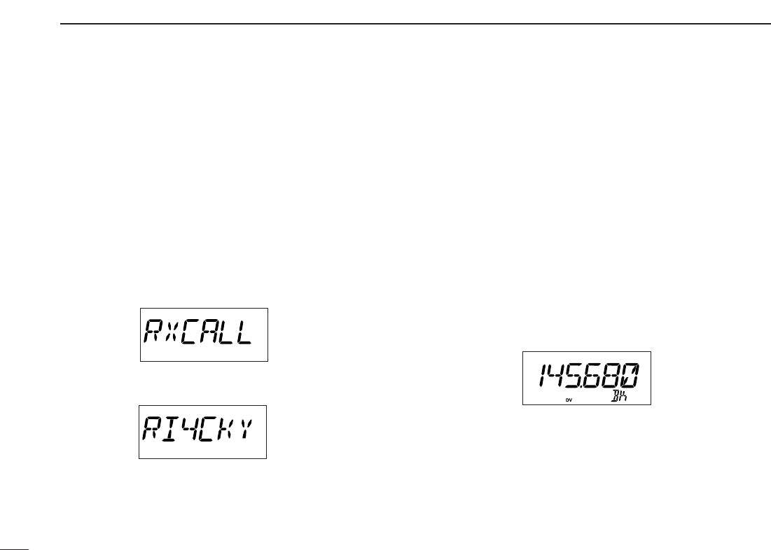
■Break-in communication
The break-in function allows you to break into an another sta-
tions communications in both Digital voice and slow data op-
eration.
qWhile receiving an another stations communication, push
[SET• LOCK] to enter call sign set mode.
•Rotate [DIAL] to select “CALLS,” if “SET” or “MESSAG” is dis-
played.
wPush [SET•LOCK] or [S.MW•MW] several times to select
received call indication, then set the either station/repeater
call sign into “MyCALL,” “UrCALL,” “RPT1 C” and “RPT2
C.”
ePush [TONE•T-SCAN] for 1 sec. to turn the break-in set-
ting ON.
•“BK” appears.
rWhen both stations are in standby, transmit to send a
break-in call.
•Programmed call sign station receives the break-in call as well
as your call sign.
tWait for the reply call from the station who receive the
break-in call.
yAfter receive the reply call, communicate normal way.
uTo cancel the break-in, push [TONE•T-SCAN] for 1 sec. to
turn OFF.

80
12
DIGITAL MODE OPERATION
1
2
3
4
5
6
7
8
9
10
11
12
13
14
15
16
■EMR communication
The EMR communication mode is available for Digital modes
operation. In the EMR call, no call sign setting is necessary.
qSet the desired frequency then push and hold
[MONI•DTMF] until 4 beep sound to turn the EMR setting
ON.
•“EM” appears.
wOperate the transceiver normal way.
eTo cancel the EMR communication mode, push
[MONI•DTMF] for 1 sec. to turn OFF.
The digital code (CSQL) or call sign (DSQL) squelch opens
only when receiving a voice signal with the same pre-pro-
grammed digital code or call sign, respectively. The digital
code or call sign squelch does not function while in a slow
data communication.
qSet the operating frequency.
wProgram the digital code or call sign in setting mode.
•See p. 69, “Digital code setting” or pgs. 59, 60 “Call sign programming.”
ePush [TONE•T-SCAN] several times until “CSQL” or
“DSQL” appears in the function display.
•“CSQL” for digital code squelch; “DSQL” for call sign squelch
operation.
rWhen a signal with the matched digital code/call sign is re-
ceived, the squelch opens and the signal can be heard.
•When the received signal includes an unmatched digital
code/call sign, the squelch does not open. However, the S/RF
indicator shows the received signal strength.
•To open the squelch manually, push [MONI•DTMF] momentarily.
tOperate the transceiver in the normal way (push [PTT] to
transmit; release [PTT] to receive).
yTo cancel the digital code/call sign squelch, push
[TONE•T-SCAN] several times until “CSQL” or “DSQL”
disappears.
✔
While scanning in digital mode:
• The call sign squelch function deactivate, then after can-
celling the scan it will activate again.
• Scan stops near channel in a 5 kHz tuning steps, and then
no sound comes out.
■Digital code/Call sign squelch operation
81
12 DIGITAL MODE OPERATION
■Slow data communication
In addition to the digital voice communication, a slow data
communication is available (Refer p. 5 about the transceiver-
PC connection details).
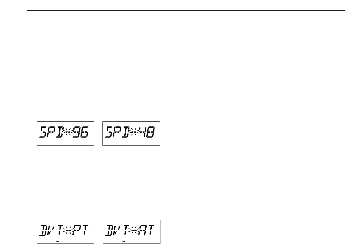
qWhile pushing [SET•LOCK], push [PWR] for 1 sec. to
enter initial set mode. (see p. 61)
wPush [SET•LOCK] or [S.MW•MW] several times to select
the data communication speed setting. (see p.64)
•“SPD” appears.
•Select suitable data speed for your PC or application.
eSet the desired frequency.
rSet another settings, such as repeater call, digital code
squelch, transmit output power.
tPush [SET•LOCK] to enter set mode.
•Rotate [DIAL] to select “SET,” if “CALLS” or “MESSAG” is dis-
played.
yPush [SET•LOCK] or [S.MW•MW] several times to select
the automatic data transmission setting. (see p.82)
•“DVT” appears.
•Skip this setting, if you want to transmit manually.
uStart up the slow data communication application.
iSet the application as follows.
•Port : The same COM port number as ID-800H’s
•Baud rate : 4800 bps or 9600 bps (same as step w)
•Data : 8 bit
•Parity : None
•Stop : 1 bit
•Flow control : Xon/Xoff
oTransceiver automatically transmits or receive the data
when you sending data to transceiver. Or push and hold
[PTT] to transmit, release to receive the data manually.
•Refer to the instruction of the application that how to send or re-
ceive data.
82
12
DIGITAL MODE OPERATION
1
2
3
4
5
6
7
8
9
10
11
12
13
14
15
16
■Other setting items
qDuring digital mode operation, push [SET•LOCK] to enter
set mode.
•Rotate [DIAL] to select “SET,” if “CALLS“ or “MESSAG” is dis-
played.
wPush [SET•LOCK] or [S.MW•MW] to select the desired
item.
eRotate [DIAL] to select the desired value or condition.
zDuring digital mode operation, push [
SET
B
(D-OFF)] to enter set mode, then push [YY]
or [ZZ]to select “SET” if necessary.
xPush [
SET
B(D-OFF)] or [
ENT
C (T-OFF)]
several times to select the desired item.
cPush [YY]or [ZZ]to select the desired value
or condition.
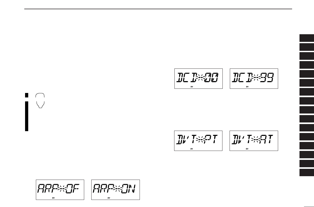
DDAuto Reply
During Digital mode operation, auto reply function is avail-
able. This function replys to an individual station call even you
are away from the transceiver. (default: OFF)
After the manual transmission (pushing [PTT]), the Auto
Reply setting is return to OFF automatically.
DDDigital Code
Sets the desired digital code for digital code squelch opera-
tion. Total of 100 codes (00–99) are available. (default: 00)
DDAuto data Transmission
During slow data operation, auto data transmission function
is available. This function transmits when data are input from
PC via the [DATA] jack. (default: PTT)
BANK/OPTION
83
12 DIGITAL MODE OPERATION
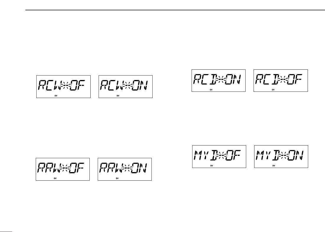
DDAuto RxCall Write
When an individual station call is received, the calling station
call sign can be stored automatically. The stored call sign can
be re-called when selecting a station call sign.
(default: OFF)
DDAuto Rx RepeaterCall Write
When an individual station call via the repeater is received,
the repeater call sign can be stored automatically. The stored
repeater’s call sign can be re-called when selecting a re-
peater call sign.
(default: OFF)
DDAuto RxCall Display
When an individual station call is received, the calling station
call sign can be indicated automatically.
(default: ON)
DDAuto MyCALL Display
Sets auto MyCALL display function ON and OFF. When this
setting is set to ON, the transceiver automatically indicates
your programmed call sign at turning power ON or digital
mode transmission. (default: OFF)
84
12
DIGITAL MODE OPERATION
1
2
3
4
5
6
7
8
9
10
11
12
13
14
15
16
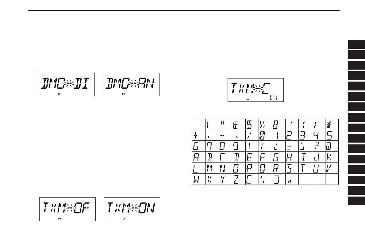
DDDigital Monitor
Sets the desired monitoring mode during digital mode opera-
tion from “DI(Digital)” and “AN(Analog).” (default: DI)
Select “ANALOG” when using FM mode for monitoring.
DDMessage Transmission
Select the Message transmission function ON and OFF.
When ON is selected, transceiver transmits a text message
(pre-programmed). (default: OFF)
qPush [SET•LOCK] to enter message set mode.
•Rotate [DIAL] to select “MESSAG,” if “CALLS” or “SET” is dis-
played.
wPush [SET•LOCK] or [S.MW•MW] several times to select
the message transmission setting.
•“TXM” appears.
DDTX message
TX messages are available up to 6 channels and each chan-
nel can be programmed up to 20 characters message. Avail-
able characters are 0to 9, Ato Z(capital letters only), some
symbols and space. (shown below table)
(3)
(D)
(N)
(X)
(+) (4)
(E)
(O)
(Y)
(–) (5)
(F)
(P)
(Z)
(✱)
(6)
(G)
(Q)
(/)
(7)
(H)
(R)
(,)
(8)
(I)
(S)
(space)
(9)
(T)
(0)
(A)
(U)
(1)
(B)
(V)
(2)
(C) (J) (K)
(L)
(M)
(W)
(.)
(
))((
)(’)(&)(
%
)($)(#)(!)
(<)(:) (;) (=) (>) (?)
(@)
([) (\) (]) (^)

85
12 DIGITAL MODE OPERATION
DDTX message programming
ATX message channel C1 must be programmed, if you want
to use the GPS message. The GPS message is transmitted
from channel C1 only.
qPush [SET•LOCK] to enter message set mode.
•Rotate [DIAL] to select “MESSAG,” if “CALLS” or “SET” is dis-
played.
wPush [SET•LOCK] or [S.MW•MW] several times until
“TXM-C” appears, then push [BAND].
eRotate [DIAL] to select the message channel.
•One of either “C1” to “C6” flashes.
rPush [BAND] to set into message programming condition.
•The 1st digit blinks and channel indication stops blinking.
tRotate [DIAL] to set the desired character.
yPush [SET•LOCK] to select 2nd digit, then rotate [DIAL] to
set the desired character.
•2nd digit blinks (1st digit stop blinking).
•Repeat this step for programming.
uPush [BAND] to set the message.
yRepeat steps wto yto set another message channels.
uPush any key below the display to exit the message set
mode.
86
12
DIGITAL MODE OPERATION
1
2
3
4
5
6
7
8
9
10
11
12
13
14
15
16
■GPS operation
The ID-800H can indicate the current position (Latitude and
Longitude) when a GPS receiver (compatible with an RS-
232C output/NMEA format/4800 bps) is connected to [DATA]
jack. And also can transmit the position data and message to
other stations.
DDPosition indication
qWhile connecting a GPS receiver and operating digital
mode, push [SET•LOCK] to enter set mode.
•Rotate [DIAL] to select “SET,” if “CALLS” or “MESSAG” is dis-
played.
wPush [SET•LOCK] or [S.MW•MW] several times to select
the GPS setting.
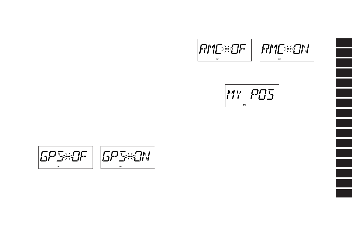
•“GPS” appears.
eRotate [DIAL] to set the GPS setting ON, then push
[BAND] to enter the sentence formatter set mode.
rPush [SET•LOCK] or [S.MW•MW] several times to select
the suitable sentence formatter for the connecting GPS re-
ceiver.
•For your position indication is necessary to set “GGA” or “RMC” is
ON
tPush [BAND] to return to set mode.
yPush [SET•LOCK] several times to select the position in-
dication.
uPush [BAND] to enter the position indication.
•Latitude and longitude date appear in order as below.
yAfter checking the current position, push any key below the
display to return to normal operating mode.
87
12 DIGITAL MODE OPERATION
DDGPS Automatic transmission
qWhile connecting a GPS receiver and operating digital
mode, push [SET•LOCK] to enter set mode.
•Rotate [DIAL] to select “SET,” if “CALLS” or “MESSAG” is dis-
played.
wPush [SET•LOCK] or [S.MW•MW] several times to select
the GPS automatic transmission.
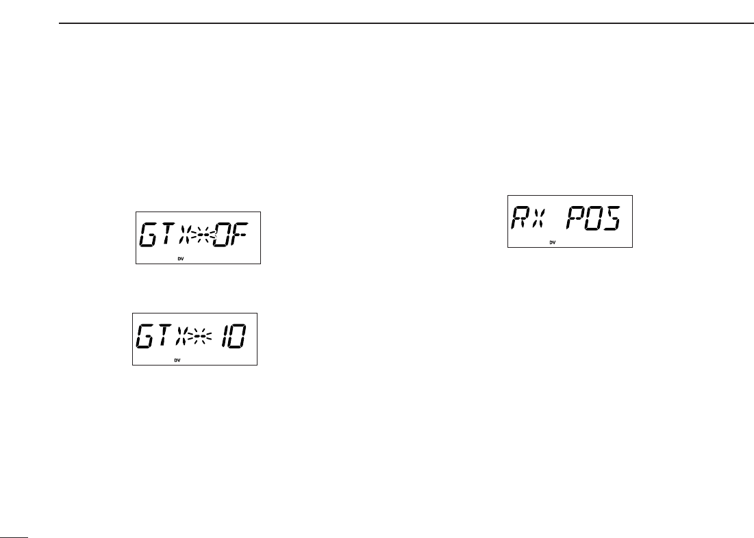
•“GTX” appears.
eRotate [DIAL] to set the interval time for the GPS auto-
matic transmission.
•Interval time is selectable from 0.5 (30 sec.), 1, 3, 5, 10, 30 min.
•When TX message channel
“C1” is
programmed, GPS transmis-
sion automatically transmits TX message “C1.”
rPush any key below the display to exit set mode.
DDReceiving a GPS transmission
qPush [SET•LOCK] to enter set mode.
•Rotate [DIAL] to select “SET,” if “CALLS” or “MESSAG” is dis-
played.
wPush [SET•LOCK] or [S.MW•MW] several times to select
the received position.
•“RX POS” appears.
ePush [BAND] to enter the position indication.
•Latitude data and longitude date appear alternately.
rPush [BAND], then [SET•LOCK] to select the received
GPS message.
tPush [BAND] to enter the message.
•Received message is indicated, push [SET•LOCK] or
[S.MW•MW] to move the cursor to right or left, respectively.
yAfter checking a received position and message, push any
key below the display to return to normal operating mode.

1-1-32 Kamiminami, Hirano-ku, Osaka 547-0003 Japan
A-6394D-1EX
Printed in Japan
©2004 Icom Inc.