ICOM orporated 278800 VHF/UHF Digital Transceiver User Manual ID 800H FCC
ICOM Incorporated VHF/UHF Digital Transceiver ID 800H FCC
UserManual.wiki
>
ICOM orporated
>
278800 User Manual
>
Users Manual Part 2
Contents
1.
Users Manual Part 1
2.
Users Manual Part 2
Users Manual Part 2
Navigation menu
Upload a User Manual
Namespaces
Wiki Guide
HTML
PDF
Info
Views
User Manual
Discussion / Help
Navigation
![478PRIORITY WATCH■Priority watch operationqSelect VFO mode; then, set an operating frequency.wSet the watching channel(s).For memory channel watch:Select the desired memory channel.For memory scan watch:Select memory mode; then, push [V/MHz•SCAN] for 1 sec.to start memory scan.For call channel watch:Select the desired call channel by pushing [M/CALL•PRIO]once or twice, then push [BAND].ePush [M/CALL•PRIO] for 1 sec. to start the watch.•The transceiver checks the memory or call channel every 5 sec.•The watch resumes according to the selected scan resume con-dition. (p. 45)•While the watch is pausing, pushing [M/CALL•PRIO] resumesthe watch manually.rPush [M/CALL•PRIO] for 1 sec. to stop the watch.zSelect VFO mode; then, set the desired fre-quency.xSet the watching channel(s).For memory channel watch:Push [MR/CALL] then [Y] or [Z] to select the de-sired memory channel.For memory scan watch:Push [MR/CALL], then push [SCAN2] to start thememory scan.For call channel watch:Push [MR/CALL] for 1 sec. then push [BAND] toselect the call channel.cPush [PRIO3(PTT-M)] to start the watch.•The transceiver checks the memory or call channelevery 5 sec.•The watch resumes according to the selected scan re-sume condition. (p. 45)•To resume the watch manually when paused, push[PRIO3(PTT-M)] or [CLRA(MW)].vTo stop the watch, push [CLRA(MW)] once (ortwice while watch is paused).PRIO3](https://usermanual.wiki/ICOM-orporated/278800.Users-Manual-Part-2/User-Guide-473909-Page-1.png)
![489DTMF MEMORY ENCODER89■Programming a DTMF codeDTMF tones are used for autopatching, controlling otherequipment, etc. The transceiver has 16 DTMF memory chan-nels (D0–DF) for storage of often-used DTMF codes of up to24 digits.qPush [MONI•DTMF] for 1 sec. to turn the DTMF encoderON.•“d” appears in place of 100 MHz digit.wPush [SET•LOCK] to enter the DTMF memory program-ming condition.•The DTMF memory channel indication blinks.eRotate [DIAL] to select the desired DTMF memory chan-nel.rPush [SET•LOCK].•The first digit blinks.tRotate [DIAL] to select the desired code.yPush [SET•LOCK] to select the next digit.•Pushing [S.MW•MW] moves the cursor backward.uRepeat the steps tand yto set the desired DTMF tonesequence.•The S/RF indicator shows the digit group. The indication in-creases every 6 digits.iPush [MONI•DTMF]to exit DTMF memory programmingcondition.•Return to the previous indication as in step q.[EXAMPLE]: Programming “5428AB453” into DTMF memory channel “D4.”PushPush then rotate Repeat the previous step until the desired code is entered. PushRotatePush for 1 sec.](https://usermanual.wiki/ICOM-orporated/278800.Users-Manual-Part-2/User-Guide-473909-Page-2.png)
![499DTMF MEMORY ENCODERDProgramming a DTMF code— via microphonezPush [FUNC] then [LOW6(DTMF)] to turn theDTMF encoder ON.•“d” appears in place of 100 MHz digit.xPush [SETB(D-OFF)] to enter the DTMF memoryprogramming condition.cPush [Y] or [Z] to select the desired DTMFmemory channel.vPush the desired digit keys.•When the first digit is input, previous memory con-tents are cleared automatically.•“E” stands for “MM” and “F” stands for “# .”•Push [Y]/[Z] and repeat this step if you make a mistake.•The S/RF indicator shows the digit group. The indi-cation increases every 6 digits.bPush [VFO/LOCK] to exit the programming condition.•The [CLRA(MW)] key cannot be used to exit. If pushed, code “A”is input. Reprogram in such a case.DTMF[EXAMPLE]: Programming “5428AB453” into DTMF memory channel “D4.”PushPush PushPushPush then .](https://usermanual.wiki/ICOM-orporated/278800.Users-Manual-Part-2/User-Guide-473909-Page-3.png)
![509DTMF MEMORY ENCODER9■Transmitting a DTMF codeDAutomatic transmission (DTMF memory)qPush [MONI•DTMF] for 1 sec. to turn the DTMF memoryencoder ON.• “d” appears in place of 100 MHz digit.wPush [SET•LOCK] to enter DTMF memory programmingcondition.eRotate [DIAL] to select the desired DTMF memory chan-nel.rPush [PTT] to transmit the selected DTMF memory content.tPush [MONI•DTMF] for 1 sec. to cancel the DTMF en-coder.•When the DTMF encoder is turned ON continuously, each pushof the PTT transmits the previously selected DTMF code.zPush [FUNC] then [LOW6(DTMF)] to turn theDTMF memory encoder ON.•“d” appears in place of 100 MHz digit.xPush [SETB(D-OFF)] to enter the DTMF memoryprogramming condition.cPush [Y] or [Z] to select the desired channel.vPush [PTT] to transmit the selected memory.•Exit the programming condition automatically.•Each push of [PTT] transmits the DTMF code.bPush [FUNC] then [SETB(D-OFF)] to cancel theDTMF memory encoder.•When the DTMF encoder is turned ON continuously,each push of the PTT transmits the previously se-lected DTMF code.DTransmitting a DTMF memory directlyzPush [FUNC] then [LOW6(DTMF)] to turn theDTMF memory encoder ON.•“d” appears in place of 100 MHz digit.xPush [DTMF-S] to turn the DTMF memory di-rect selection ON.•The function indicator (microphone) lights green.cPush the desired DTMF channel.•“0” to “9” and “A” to “D” are available for DTMFmemory channels.•The selected DTMF code is automatically transmit-ted without pushing PTT.NOTE: When no DTMF code programmedchannel number is pushed, it transmits the rela-tive DTMF code as the manual transmission de-scribed in the next page.vPush [DTMF-S] again to deactivate the DTMFmemory direct selection.bPush [FUNC] then [SETB(D-OFF)] to cancelthe DTMF memory encoder.DTMF-SDTMF](https://usermanual.wiki/ICOM-orporated/278800.Users-Manual-Part-2/User-Guide-473909-Page-4.png)
![519DTMF MEMORY ENCODERDManual transmissionzDeactivate the DTMF memory encoder bypushing [FUNC] then [SETB(D-OFF)].xPush [DTMF-S] to turn the DTMF direct selec-tion ON.•The function indicator (microphone) lights green.cPush one of “0” to “9” and “A” to “F” keys mo-mentarily, then push the desired DTMF keys,0–9 and A to F.• A: [CLRA(MW)] B: [SETB(D-OFF)], C: [ENTC(T-OFF)] D: [SQLYD(MUTE)], E: [MM(TONE-1)] F: [SQLZ#(16KEY-L)]•Automatically transmits without pushing PTT.•The first code, one of “0” to “9” and “A” to “F,” is nottransmitted. DTMF code transmission starts fromthe 2nd code.vPush [DTMF-S] again to deactivate the DTMFdirect selection.■DTMF speedThe rate at which DTMF memories send individual DTMFcharacters can be set to accommodate operating needs.qPush [PWR] for 1 sec. to turn power OFF.wWhile pushing [SET•LOCK], push [PWR] for 1 sec. to turnpower ON and enter initial set mode.ePush [SET•LOCK] or [S.MW•MW] several times until“DTD” appears as shown above.rRotate [DIAL] to select the desired speed as shown in thetable below.tPush [PWR] to exit initial set mode.cps=characters/secThe display shows the fastest DTMF speed is selected.USINGINITIAL SET MODEDTMF-S](https://usermanual.wiki/ICOM-orporated/278800.Users-Manual-Part-2/User-Guide-473909-Page-5.png)
![5210POCKET BEEP AND TONE SQUELCH910■Pocket beep operationThis function uses subaudible tones for calling and can beused as a “common pager” to inform you that someone hascalled while you were away from the transceiver.DWaiting for a call from a specific stationqSet the operating frequency.wPush [SET•LOCK] to enter set mode.•Rotate [DIAL] to select “SET,” if necessary.ePush [SET•LOCK] or [S.MW•MW] several times until “CT”for tone squelch or “DT” for DTCS squelch appears.rRotate [DIAL] to select the desired tone squelch frequency.tWhen operating the pocket beep function with DTCSsquelch, push [SET•LOCK] once then rotate [DIAL] to se-lect the DTCS polarity.yPush [TONE•T-SCAN] to exit set mode.uPush [TONE•T-SCAN] several times until “T SQLS” or“SDTCS” are displayed to turn ON the pocket beep withtone squelch or DTCS squelch, respectively.iWhen a signal with the matched tone is received, thetransceiver emits beep tones and blinks “S.”•Beep tones sound for 30 sec. and “S” blinks. To stop thebeeps and blinking manually, push any key. When the beeptones are not stopped manually, “S” continues blinking until[PTT] is pushed (see step o).oPush [PTT] to answer.•“S” disappears and cancels the pocket beep function auto-matically.!0 Push [TONE•T-SCAN] several times until “T SQL” or“DTCS” disappears to cancel the tone squelch or DTCSsquelch function.Push [TONE•T-SCAN] several times to select the pocket beepfunction with tone squelch or DTCS squelch.Appears when the pocket beepwith tone squelch is activated.Appears when the pocket beepwith DTCS squelch is activated.DTCS polarity settingTone squelch frequency setting DTCS code setting](https://usermanual.wiki/ICOM-orporated/278800.Users-Manual-Part-2/User-Guide-473909-Page-6.png)
![5310 POCKET BEEP AND TONE SQUELCHzSet the operating frequency.xProgram the CTCSS tone frequency or DTCScode in set mode.➥Push [SETB(D-OFF)] to enter set mode.•Push [Y] or [Z] to select “SET,” if necessary.➥Push [SETB(D-OFF)] or [ENTC(T-OFF)]several times until “CT” for tone squelch or“DT” for DTCS squelch appears.•“TSQL” blinks when tone squelch (“CT”), or“DTCS” blinks when DTCS squelch (“DT”) isselected.➥Push [Y]/[Z] to select the desired tone fre-quency or DTCS code.➥Push [SETB(D-OFF)] to select “DTP” thenpush [Y]/[Z] to select the DTCS polarity.➥Push [CLRA(MW)] to exit set mode.cPush [FUNC] then push [DUP+8(TSQLS)]or [MID5(DTCSS)] to turn ON the pocketbeep with tone squelch or DTCS squelch, re-spectively.vWhen a signal with the matched tone is re-ceived, the transceiver emits beep tones for30 sec. and blinks “S.”bPush [PTT] to answer or push [CLRA(MW)] tostop the beeps and blinking.•“S” disappears and cancels the pocket beepfunction automatically.nTo cancel the tone squelch or DTCS squelchfunction, push [FUNC] then [ENTC(T-OFF)]. •“TSQL” or “DTCS” disappears DAvailable tone frequency listNOTE: The transceiver has 50 tone frequencies and con-sequently their spacing is narrow compared to units having38 tones. Therefore, some tone frequencies may receiveinterference from adjacent tone frequencies.To prevent interference from adjacent tone frequencies,using the frequencies as in the following table, is recom-mended.DCalling a waiting station using pocket beepAsubaudible tone matched with the station’s CTCSS tone fre-quency or 3-digit DTCS code with polarity is necessary. Usethe tone squelch on the next page or a subaudible tone en-coder (pgs. 22, 23).67.069.371.974.488.591.594.897.4114.8118.8123.0127.3151.4156.7162.2167.9203.5210.7218.1225.777.079.782.585.4100.0103.5107.2110.9131.8136.5141.3146.2173.8179.9186.2192.8233.6241.8250.3• Recommended tone frequencies67.069.371.974.477.079.782.585.488.591.594.897.4100.0103.5107.2110.9114.8118.8123.0127.3131.8136.5141.3146.2151.4156.7159.8162.2165.5167.9171.3173.8177.3179.9183.5186.2189.9192.8196.6199.5203.5206.5210.7218.1225.7229.1233.6241.8250.3254.1TSQLSDTCSS](https://usermanual.wiki/ICOM-orporated/278800.Users-Manual-Part-2/User-Guide-473909-Page-7.png)
![5410POCKET BEEP AND TONE SQUELCH10■Tone/DTCS squelch operationThe tone or DTCS squelch opens only when receiving a sig-nal with the same pre-programmed subaudible tone or DTCScode, respectively.qSet the operating frequency.wProgram the CTCSS tone frequency or DTCS code in setmode.•See p. 52 for programming details.ePush [TONE•T-SCAN] several times until “T SQL” or“DTCS” appears in the function display.rWhen a signal with the matched tone is received, thesquelch opens and the signal can be heard.•When the received signal includes an unmatched tone, thesquelch does not open. However, the S/RF indicator shows thereceived signal strength.•To open the squelch manually, push [MONI•DTMF].tOperate the transceiver in the normal way (push [PTT] totransmit; release [PTT] to receive).yTo cancel the tone squelch, push [TONE•T-SCAN] severaltimes until “T SQL” or “DTCS” disappears.zSet the operating frequency.xProgram the CTCSS tone frequency or DTCScode in set mode.•See p. 52 for programming details.cPush [FUNC] then [SIMP9(TSQL)] or [HIGH4(DTCS)]to turn the tone squelch or DTCS squelch ON.vWhen a signal with the matched tone is re-ceived, the squelch opens and the signal can beheard.•When the received signal includes an unmatchedtone, the squelch does not open. However, the S/RFindicator shows the received signal strength.•To open the squelch manually, push [MONI1(BANK)].bOperate the transceiver in the normal way (push[PTT] to transmit; release [PTT] to receive).nTo cancel the tone squelch, push [FUNC] then[ENTC(T-OFF)].•“TSQL” or “DTCS” disappears. TSQLDTCS](https://usermanual.wiki/ICOM-orporated/278800.Users-Manual-Part-2/User-Guide-473909-Page-8.png)
![5510 POCKET BEEP AND TONE SQUELCH■Tone scanBy monitoring a signal that is being operated with pocketbeep, tone or DTCS squelch function, you can determine thetone frequency or DTCS code necessary to open a squelch.qSet the desired operating frequency or memory channel tobe checked for a tone frequency or code.wPush [TONE•T-SCAN] several times to select the tonetype, tone squelch or DTCS, to be scanned.•Either “T SQL” or “DTCS” appears ePush [TONE•T-SCAN] for 1 sec. to start the tone scan.•To change the scanning direction, rotate [DIAL].rWhen the CTCSS tone frequency or 3-digit DTCS code ismatched, the squelch opens and the tone frequency istemporarily programmed into the selected condition suchas memory or call channel.•The tone scan pauses when a CTCSS tone frequency or 3-digitDTCS code is detected.•The decoded CTCSS tone frequency or 3-digit DTCS code isused for the tone encoder or tone encoder/decoder dependingon the selected tone condition or type in step w. -“TSQL” : CTCSS tone encoder/decoder-“DTCS” : DTCS tone encoder/decodertPush [TONE•T-SCAN] to stop the scan.zSet the frequency or memory channel to bechecked for a tone frequency.xSelects the tone type to be scanned.•Push [FUNC] then push; [SIMP9(TSQL)] for tonesquelch; [HIGH4(DTCS)] for DTCS squelch.cPush [FUNC] then [SCAN2(T-SCAN)] to startthe tone scan.vWhen the tone frequency is matched, thesquelch opens and the tone frequency is pro-grammed into the selected mode such asmemory or call channel.bPush [CLRA(MW)] to stop the scan.☞NOTE: The decoded tone frequency is programmed tem-porarily when a memory or call channel is selected. How-ever, this will be cleared when the memory/call channel isre-selected.T-SCANDuring CTCSS frequency scan During DTCS code scanPush [TONE•T-SCAN] for 1 sec. to start tone scan.](https://usermanual.wiki/ICOM-orporated/278800.Users-Manual-Part-2/User-Guide-473909-Page-9.png)
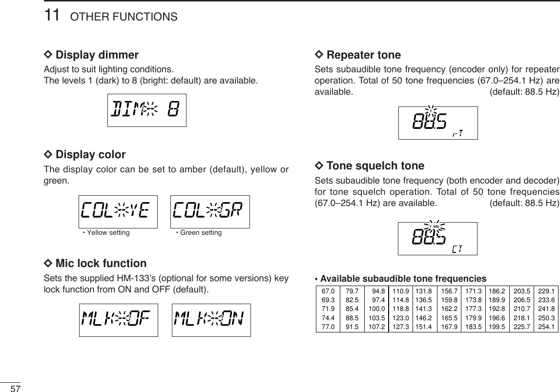
![5611OTHER FUNCTIONS1011■Set mode•Set mode operationqPush [SET•LOCK] to enter the set mode.•Rotate [DIAL] to select “SET,” if necessary.wPush [SET•LOCK] or [S.MW•MW] to select the desireditem.eRotate [DIAL] to select the condition or value.rPush[MONI•DTMF] to exit set mode.•Set mode itemszPush [SETB(D-OFF)] to enter set mode.•Push [Y] or [Z] to select “SET,” if necessary.xPush [SETB(D-OFF)] or [ENTC(T-OFF)] to selectthe desired item.cPush [Y] or [Z] to select the condition or value.vPush [CLRA(MW)] to exit set mode.SETB*Available for USA version only.†Appears when accessing set mode from VFO mode only.‡Appears when accessing set mode from memory mode only.: Push (front panel); or (microphone): Push (front panel); or (microphone)• Weather alert*• Display dimmer • Display color • Repeater tonefrequency• Tone squelchfrequency • DTCS code• DTCS polarity• Offset frequency• Tuning step• Scan resume timer• Channel skip setting‡• Bank link function‡• Mic lock function• Program skip† • Bank setting‡ • Memory name‡](https://usermanual.wiki/ICOM-orporated/278800.Users-Manual-Part-2/User-Guide-473909-Page-10.png)
![5811OTHER FUNCTIONS11DDDTCS code Sets DTCS code (both encoder and decoder) for DTCSsquelch operation. Total of 104 codes are available.(default: 023)DDDTCS polaritySets DTCS polarities for transmission and reception from“NN,” “NR,” “RN” and “RR.” (default: NN)DDOffset frequencySets the duplex offset frequency within 0 to 20 MHz range.During duplex (repeater) operation, transmit frequency shiftsthe set frequency. (default value may differ depending on operatingfrequency band and versions)DDTuning stepSelects tuning step from 5, 10, 12.5, 15, 20, 25, 30, 50, 100and 200 kHz for [DIAL] or [Y]/[Z] operation. (default value maydiffer depending on operating frequency band and versions) • Transmit: normal Receive: normal (default)• Transmit: normal Receive: reverse](https://usermanual.wiki/ICOM-orporated/278800.Users-Manual-Part-2/User-Guide-473909-Page-12.png)
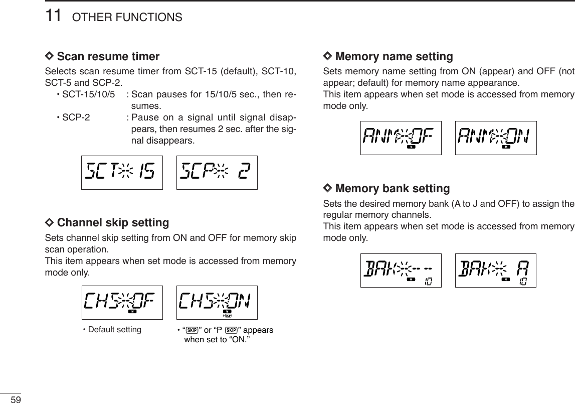
![6011OTHER FUNCTIONS11DDProgram scan skip settingSets the program scan skip setting from ON and OFF forVFO scan operation, such as programmed scan.This item appears when set mode is accessed from VFOmode only.DDWeather alert functionTurns weather alert function ON and OFF.DDMemory bank link functionSets the memory bank link function ON and OFF (default).The link function provides continuous banks scan, that scansall contents in the selected banks during bank scan.This item appears when set mode is accessed from memorymode only.•Bank link settingqRotate [DIAL] to select the memory bank link function ON.wPush [SET•LOCK] or [S.MW•MW] to select the desiredbank to be linked.•BLA: Bank A, BLB: Bank B, BLC: Bank C, BLD: Bank D, BLE: Bank E, BLF: Bank F, BLG: Bank G, BLH: Bank H, BLI: Bank I, BLJ: Bank JeRotate [DIAL] to select “ON” to linking the bank.rRepeat steps wand eto set the link condition.U.S.A. version only](https://usermanual.wiki/ICOM-orporated/278800.Users-Manual-Part-2/User-Guide-473909-Page-14.png)
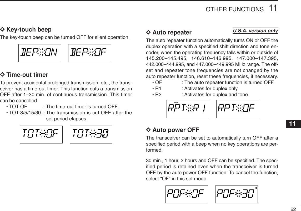
![6111 OTHER FUNCTIONS■Initial set modeThe initial set mode is accessed at power ON and al-lows you to set seldom-changed settings. In this way,you can “customize” transceiver operations to suit yourpreference and operating style.•Initial set mode itemsDDEntering initial set modeqWhile pushing [SET•LOCK], push [PWR] for 1 sec. to enterinitial set mode.wPush [SET•LOCK] or [S.MW•MW] to select the desireditem.eRotate [DIAL] to select the condition or value.rPush [PWR]momentarily to exit initial set mode.ATPOWER ON• Active band• Key-touch beep • Time-out timer • Auto repeater*• Squelch attenuator • Microphone sensitivity• Auto power off• DTMF speed• Data speed for DV mode• Stanby beep• Squelch delay• Data speed for FM mode• Cooling fan• Narrow TX*Available in the USA version only.: Push (front panel); or (microphone): Push (front panel); or (microphone)](https://usermanual.wiki/ICOM-orporated/278800.Users-Manual-Part-2/User-Guide-473909-Page-15.png)
![6311 OTHER FUNCTIONSDDCooling fan controlSelects the cooling fan control condition from Auto and ON.•Auto (AT) : The fan rotates during transmit and for 2 min.after transmission, or when the internal tem-perature of the transceiver exceeds the pre-set value until the temperature drops.•ON (ON) : The fan continuously rotates. DDData transmission speedSelects the data transmission speed for packet operationfrom 1200 bps and 9600 bps.DDSquelch delaySelects squelch delay from short and long to prevent re-peated opening and closing of the squelch during receptionof the same signal.•S : Short squelch delay.•L : Long squelch delay.DDMicrophone sensitivitySelects the microphone sensitivity from high (H) and low (L)to suits your preference.DDSquelch attenuatorTurns the squelch attenuator function ON and OFF.•ON: The squelch attenuator activates when [SQL]control is set between 12 o’clock and fullyclockwise position.•OF: The squelch attenuator does not function.](https://usermanual.wiki/ICOM-orporated/278800.Users-Manual-Part-2/User-Guide-473909-Page-17.png)
![6411OTHER FUNCTIONS11DDActive bandSelects the frequency selecting condition via [DIAL] or [Y]/[Z]on the microphone from all (AL) and single (SI).•All (AL) : The operating frequency can be selectedcontinuously.•Single (SI) : The operating frequency can be selectedwithin the current band. Pushing [BAND] for1sec. then tuning dial rotation is necessaryfor frequency band selection.DDNarrow TX functionSelect the narrow TX function ON and OFF.•ON: Enables the FM-narrow mode transmission. Thedeviation (modulation level) becomes half fromthe regular FM transmission can be performed.• OFF : Inhibits the FM-narrow mode transmission. Theregular FM deviation transmission is performed(“NAR” indication disappears while transmission)even when FM-narrow is selected.DDDTMF speedThe rate at which DTMF memories send individual DTMFcharacters can be set to accommodate operating needs.•1 : 100 msec. interval; 5.0 cps speed•2 : 200 msec. interval; 2.5 cps speed •3 : 300 msec. interval; 1.6 cps speed •5 : 500 msec. interval; 1.0 cps speed DDData SpeedSelect the communication speed between the transceiver andPC from 4800 baud or 9600 baud. (default: 9600) DDStandby BeepTurns the beep emission capability when the communicatingstation finishes transmitting or the receive signal disappears.while in the digital mode operation. (default: OFF)](https://usermanual.wiki/ICOM-orporated/278800.Users-Manual-Part-2/User-Guide-473909-Page-18.png)
![6511 OTHER FUNCTIONS■AM/FM narrow modeThe ID-800H has AM mode reception and FM narrow mode isavailable. Typically, AM mode is used for the air band(118–135.995 MHz).qSelect the desired frequency band in VFO mode, or the de-sired memory channel.wPush [BAND] for 1 sec. to select AM/FM narrow mode asdesired.•“NAR” (FM narrow), “AM” and “NAR AM” appears in sequence.• No indicationstands for FM mode.zPush [BAND] or [MR/CALL] to select the desiredfrequency band or memory channel.xPush [BAND] for 1 sec. to select AM/FM narrowmode as desired.•“NAR”, “AM” and “NAR AM” appears in sequence.• No indicationstands for FM mode.SETB• When FM narrow mode is selected• When AM mode is selected• When AM narrow mode is selected](https://usermanual.wiki/ICOM-orporated/278800.Users-Manual-Part-2/User-Guide-473909-Page-19.png)
![6611OTHER FUNCTIONS11■Weather channel operation(USA version only)DDWeather channel selectionqPush [M/CALL•PRIO] several times to select weatherchannel group. wRotate [DIAL] to select the desired weather channel. ePush [M/CALL•PRIO] to select memory mode, or push[V/MHz•SCAN] to select VFO mode.DDWeather alert functionNOAA broadcast stations transmit weather alert tones beforeimportant weather announcements. When the weather alertfunction is turned ON, the selected weather channel is moni-tored each 5 sec. for the announcement. When the alert sig-nal is detected, the “AL.T” and the WX channel are displayedalternately and sounds a beep tone until the transceiver is op-erated. The previously selected (used) weather channel ischecked periodically during standby or while scanning.qSelect the desired weather channel.wTurn the weather alert function ON in set mode.➥Push [SET•LOCK] to enter set mode.➥Push [SET•LOCK] or [S.MW•MW] to select the weatheralert item, then rotate [DIAL] to set ON.➥Push [MONI•DTMF] to exit set mode.eSets the desired stand-by condition.•Selects VFO, memory or call channel.•Scan or priority watch operation can also be selected.rWhen the alert is detected, a beep sounds and the follow-ing indication will be displayed.tTurn the weather alert function OFF in set mode.☞NOTE: While receiving a signal (on a frequency other thanthe weather alert ON frequency), the receiving signal oraudio will be interrupted momentarily every 5 sec. (approx.)in case the alert function is turned ON. This symptom iscaused by the WX alert function. To cancel these symp-toms, set the weather alert item OFF in set mode.Shows above indications alternately.Weather channel group indicaiton[M/CALL•PRIO]](https://usermanual.wiki/ICOM-orporated/278800.Users-Manual-Part-2/User-Guide-473909-Page-20.png)
![6711 OTHER FUNCTIONS■Microphone keysThe supplied HM-133’s (optional for some versions) [F-1] and[F-2] keys memorize the transceiver conditions. The [UP]/[DN] keys of the standard or an optional microphone(other than the HM-133) can be assigned functions like thefunction keys on the transceiver’s front panel.DD[UP]/[DN] keys on a microphones(other than HM-133)The following functions are assigned to [UP]/[DN] keys on theother microphones (HM-118N/TAN, etc.) when first applyingpower.•Default setting[UP] : channel up; push and hold to start scan, push againto stop scan.[DN] : channel down; push and hold to start scan, pushagain to stop scan.➥Assigning a functionqTurn the power OFF.wWhile pushing the desired switch on the transceiver andone of either [UP]/[DN] keys on the microphone, turn thepower ON.•The function is programmed into the key.➥Clearing an assignmentqTurn the power OFF.wWhile pushing the desired [UP] or [DN] key on the micro-phone, turn the power ON.DD[F-1]/[F-2] keys on HM-133The following conditions can be memorized into [F-1] and [F-2] keys, independently.•Operating frequency•Repeater setting (offset direction and frequency, tone ON/OFFand frequency)•Tone/DTCS squelch (ON/OFF, frequency/code and polarity)•Transmit output power selection•Tuning step•Operating mode selection (FM/AM)➥Programming the band conditionPush [F-1]/[F-2] for 1 sec.•3 beeps sound.➥Recalling the band conditionPush [F-1]/[F-2] momentarily.➥Initializing the band conditionPush [FUNC] then push [F-1]/[F-2].The following conditions are initialized.•Operating band: 145 MHz band•Repeater setting (tone frequency: 88.5 Hz, offsetfrequency: 600 kHz)•Tone/DTCS squelch (ON/OFF: OFF, tone fre-quency:88.5 Hz, DTCS code: 023 and polarity: NN)•Transmit output power selection: HIGH•Tuning step: 5 kHz•Call channel: 1 CH, memory channel: 1CH•Operating mode selection: FM[F-1]/[F-2]ATPOWER ON](https://usermanual.wiki/ICOM-orporated/278800.Users-Manual-Part-2/User-Guide-473909-Page-21.png)
![6811OTHER FUNCTIONS11■Partial resetIf you want to initialize the operating conditions (VFO fre-quency, VFO settings, set mode contents) without clearingthe memory contents.➥While pushing [V/MHz•SCAN] and [SET•LOCK], push[PWR] for 1 sec. to partially reset.■All resetThe function display may occasionally display erroneous in-formation (e.g. when first applying power). This may becaused externally by static electricity or by other factors.If this problem occurs, turn power OFF. After waiting a fewseconds, turn power ON again. If the problem persists, per-form the following procedure.•Partial resetting is also available. See left for details.IMPORTANT!:Resetting the transceiver CLEARS all memory informationand initializes all values in the transceiver.➥While pushing [S.MW•MW] and [SET•LOCK], push [PWR]for 1 sec. to reset the CPU.[S.MW•MW][SET•LOCK] [PWR]ATPOWER ON[S.MW•MW][PWR][V/MHz•SCAN]ATPOWER ON](https://usermanual.wiki/ICOM-orporated/278800.Users-Manual-Part-2/User-Guide-473909-Page-22.png)
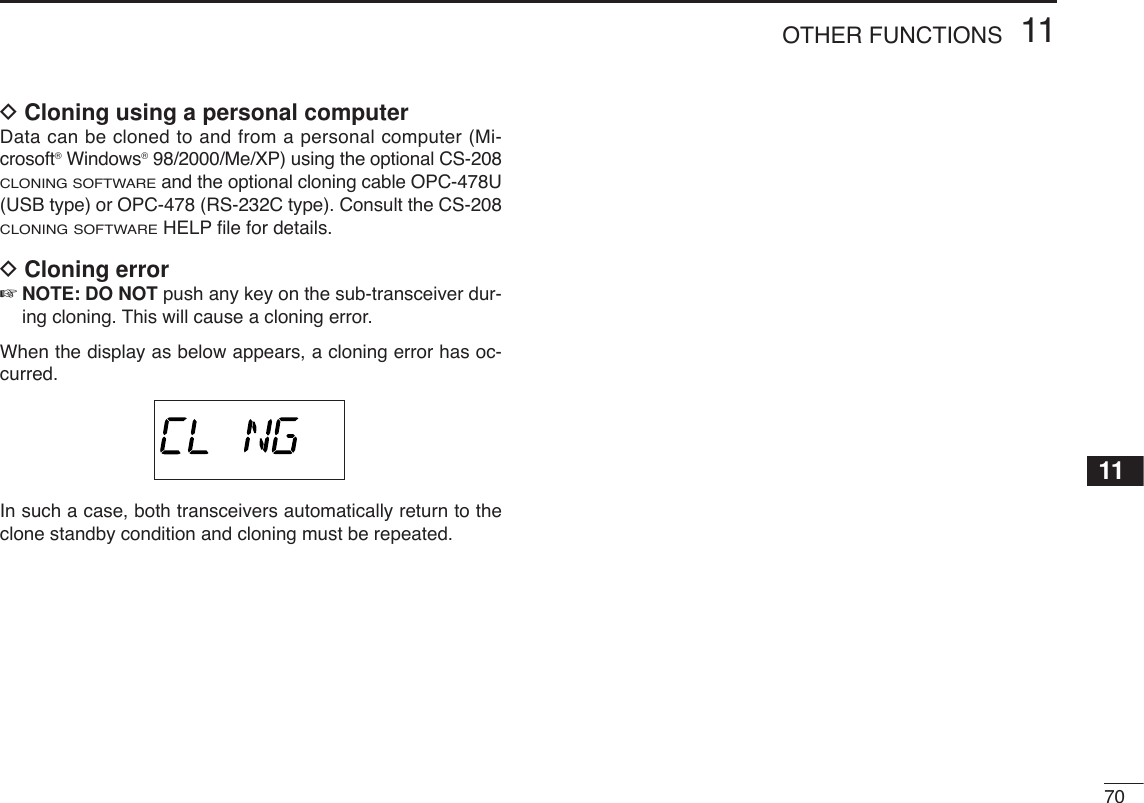
![6911 OTHER FUNCTIONS■Data cloningCloning allows you to quickly and easily transfer the pro-grammed contents from one transceiver to another; or datafrom a personal computer to a transceiver using the optionalCS-D800 CLONING SOFTWARE.DCloning between transceiversqConnect the OPC-474 cloning cable to [SP] jack of themaster and sub-transceivers.•The master transceiver is used to send data to the sub-trans-ceiver.wWhile pushing [M/CALL•PRIO], turn power ON to entercloning mode (master transceiver only— power on only forsub-transceiver).•“CLONE” appears and the transceivers enter the clone standbycondition.ePush [SET•LOCK] on the master transceiver.•“CL OUT” appears in the master transceiver’s display and theS/RF indicators show that data is being transferred to the sub-transceiver.•“CL IN” appears automatically in the sub-transceiver’s displayand the S/RF indicators show that data is being received fromthe master transceiver.rWhen cloning is finished, turn power OFF, then ON to exitcloning mode.Pushing [SET•LOCK] start cloning.While pushing [M/CALL•PRIO], turn power ON.[PWR][M/CALL•PRIO]To [SP] To [SP]ATPOWER ON](https://usermanual.wiki/ICOM-orporated/278800.Users-Manual-Part-2/User-Guide-473909-Page-23.png)
![7111 OTHER FUNCTIONS■Packet operationDData speedFor packet operation, the transceiver can be set to one of twodata speeds: 1200 bps or 9600 bps.qWhile pushing [SET•LOCK], push [PWR] for 1 sec. to enterinitial set mode.wPush [SET•LOCK] or [S.MW•MW] to select the ‘BPS’ item.eRotate [DIAL] to select the desired data speed.rPush [PWR]to exit initial set mode.For 1200 bps operation—•Disconnect the microphone plug from the microphoneconnector during data transmission, otherwise the datasignal and voice signal are simultaneously transmitted.For 9600 bps operation—•When the transceiver is set for 9600 bps data transmis-sion in set mode, the microphone signal is automaticallycut. Therefore, it is not necessary to disconnect the mi-crophone plug from the connector in this case.•When pushing [PTT] during data transmission, data trans-mission is interrupted and voice signals have priority.D1200 bps packet operationqConnect the transceiver and a TNC as illustrated below.wSet the TNC for transmit.eSet transmit delay on the TNC.rAdjust the TNC frequency deviation if necessary.•When using a deviation meter:Adjust the output of the TNC so that frequency deviationis in the range ± 3 to ±4 kHz.•When NOT using a deviation meter:Areceiver or transceiver is needed to monitor the trans-mission—compare the received audio output level whenreceiving a TNC modulated signal with high level voicesignals using the microphone. Then adjust the TNC mod-ulated signal to a lower level than the voice modulatedsignal.SQLPTTRX AUDIOGNDTX AUDIOTNC sideq DATA INw GNDe PTT Pt AF OUTy P SQL](https://usermanual.wiki/ICOM-orporated/278800.Users-Manual-Part-2/User-Guide-473909-Page-25.png)
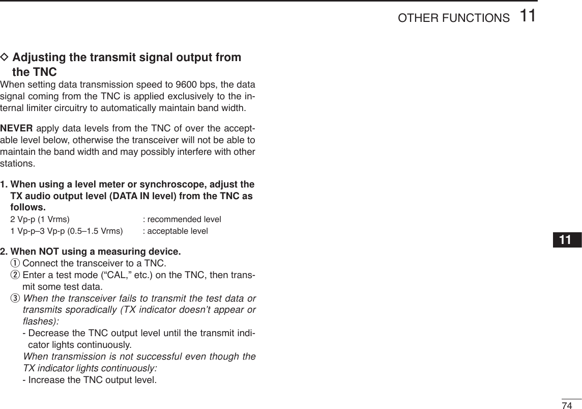
![7311 OTHER FUNCTIONSD9600 bps high speed packet operationThe transceiver supports 2 modes of 9600 bps packet opera-tion: G3RUH and GMSK.qConnect the transceiver and a TNC as illustrated below.wG3RUH mode can handle 16 kinds of modulated waveforms in order to maintain a communication link.eSet transmit delay on the TNC.rAdjust the TNC frequency deviation if necessary (see pageat right).•When using the PTT P terminal for packet operation, novoice signals are transmitted from the microphone.•When pushing [PTT] during data transmission, datatransmission is interrupted and the voice signal takes pri-ority.•Read the instructions supplied with your TNC carefullybefore attempting packet operation with the transceiver.•Pin rDATA OUT is for 9600 bps operation only. This pincannot be used for 1200 bps operation.TNC sideSQLPTTRX AUDIOGNDTX AUDIOq DATA INw GNDe PTT P r DATA OUTy P SQL](https://usermanual.wiki/ICOM-orporated/278800.Users-Manual-Part-2/User-Guide-473909-Page-27.png)
![75DIGITAL MODE OPERATION12■Digital mode operationThe ID-800H can be operated for digital voice mode and slowdata operation for both transmit and receive. Also availablefor connecting GPS receiver (compatible with an RS-232Coutput/NMEA format/4800 bps) and transmit/receive positiondata.■Call sign programming4 kind of call sign memories are available for your own callsign “MyCALL,” other station call sign “UrCALL” and nearestrepeater call sign “RPT1 C” and another zone’s repeater callsign “RPT2 C.” Each call sign memory can be stored up to 6call signs, and each call sign programmed up to 8 characters.DDYour call sign programmingYour call sign must be programmed for both Digital voice andslow data communications (including GPS transmission). qPush [SET•LOCK] to enter call sign set mode.•Rotate [DIAL] to select “CALLS,” if “SET” or “MESSAG” is dis-played.wPush [SET•LOCK] or [S.MW•MW] several times to select“MyCALL,” then push [BAND].eRotate [DIAL] to select the desired call sign channel.ePush [BAND] to set into call sign programming condition.•The 1st digit blinks and channel indication stops blinking.rRotate [DIAL] to set the desired character or code.•Push [SET•LOCK] or [S.MW•MW] to move the cursor to right orleft, respectively.•Push [V/MHz] to cancel and exit the call sign programming.tPush [SET•LOCK] to select 2nd digit, then rotate [DIAL]to set the desired character or code.•2nd digit blinks (1st digit stop blinking).•Repeat this step for programming your call sign.yPush [BAND] twice to fix the call sign.uRotate [DIAL] to select an another channel from “C1” to“C6.”iRepeat steps wto yto program your call sign channels.](https://usermanual.wiki/ICOM-orporated/278800.Users-Manual-Part-2/User-Guide-473909-Page-29.png)
![7612DIGITAL MODE OPERATION12345678910111213141516DDStation/Repeater1/2 call sign programming Station call sign must be programmed for the specified sta-tion call as well as repeater operation in both Digital voice andslow data communications.qPush [SET•LOCK] to enter call sign set mode.•Rotate [DIAL] to select “CALLS,” if “SET” or “MESSAG” is dis-played.wPush [SET•LOCK] or [S.MW•MW] several times to selectthe call sign item, then push [BAND].•“UrCALL” appears for station call sign.•“RPT1 C” or “RPT2 C” appears for repeater call sign.eRotate [DIAL] to select the desired call sign channel.ePush [BAND] to set into call sign programming condition.•The 1st digit blinks and channel indication stops blinking.rRotate [DIAL] to set the desired character or code.•Push [SET•LOCK] or [S.MW•MW] to move the cursor to right orleft, respectively.•Push [V/MHz] to cancel and exit the call sign programming.tPush [SET•LOCK] to select 2nd digit, then rotate [DIAL]to set the desired character or code.•2nd digit blinks (1st digit stop blinking).•Repeat this step for programming station/repeater call sign.yPush [BAND] twice to fix the call sign.uRotate [DIAL] to select an another channel from “C1” to“C6.”iRepeat steps wto yto program another station/repeatercall sign channels.✔For your information:Repeater call sign can be programmed gateway connectioncapabilities at step rfor connecting to the other Area orZone.•“G” appears or disappears at the 8th digit when each pushing[M/CALL].](https://usermanual.wiki/ICOM-orporated/278800.Users-Manual-Part-2/User-Guide-473909-Page-30.png)
![7712 DIGITAL MODE OPERATION■Digital voice mode operationqSet the desired frequency in VFO mode. (pgs. 11, 12)•Select output power, if desired. (p.17)wPush [BAND ] for 1 sec. to enter the mode selec-tion condition.eRotate [DIAL] to select “DV,” then push [BAND ] toset the digital mode.•“DV” appears.rPush [SET•LOCK] to enter the call sign set mode.•Rotate [DIAL] to select “CALLS,” if “SET” or “MESSAG” is dis-played.tPush [SET•LOCK] or [S.MW•MW] several times until “MyCALL” apperes.yRotate [DIAL] to select the desired your call sign channel,if you have programmed several call signs.DDWhen sending a CQuSelect “CQ” as the call sign.-Push [SET• LOCK] to select the call sign select mode.•Rotate [DIAL] to select “CALLS,” if “SET” or “MESSAG” is dis-played.-Push [SET•LOCK] or [S.MW•MW] several times until “Ur-CALL” appears, then push [BAND].-Rotate [DIAL] to select the desired channel then push[BAND].-Push [V/MHz] to edit “CQCQCQ.”-Push any key below the display to exit call sign set mode.iPush and hold [PTT] to transmit and speak into the micro-phone at normal voice level.•Transmit indicator appears and the RF meter shows the output power.oRelease [PTT] to return to receive.•The other station call sign will be received.•Received call signs can be stored into the received call recordautomatically. See page 79 for details.AppearsMODEMODE](https://usermanual.wiki/ICOM-orporated/278800.Users-Manual-Part-2/User-Guide-473909-Page-31.png)
![7812DIGITAL MODE OPERATION12345678910111213141516DDWhen calling the desired stationuSelect the desired call sign.-Push [SET• LOCK] to select the call sign select mode.•Rotate [DIAL] to select “CALLS,” if “SET” or “MESSAG” is dis-played.-Push [SET•LOCK] or [S.MW•MW] several times until “Ur-CALL” appears, then push [BAND].-Rotate [DIAL] to select the desired call sign (pre-pro-grammed), or set the desired call sign. (see p. 76)-Push any key below the display to exit call sign set mode.iPush and hold [PTT] to transmit and speak into the micro-phone at normal voice level.•Transmit indicator appears and the RF meter shows the output power.oRelease [PTT] to return to receive.•The other station call sign will be received.•Received call signs can be stored into the received call recordautomatically. See page 79 for details.NOTE: The digital mode operation is vastly different than FMmode. One of the differences is in the digital mode thesquelch does not function as FM mode, changing the squelchsetting will not open to hear the hiss of “White Noise,” onlyactivate for digital squelch function as CSQL (Digital codesquelch) or DSQL (Call sign squelch).](https://usermanual.wiki/ICOM-orporated/278800.Users-Manual-Part-2/User-Guide-473909-Page-32.png)
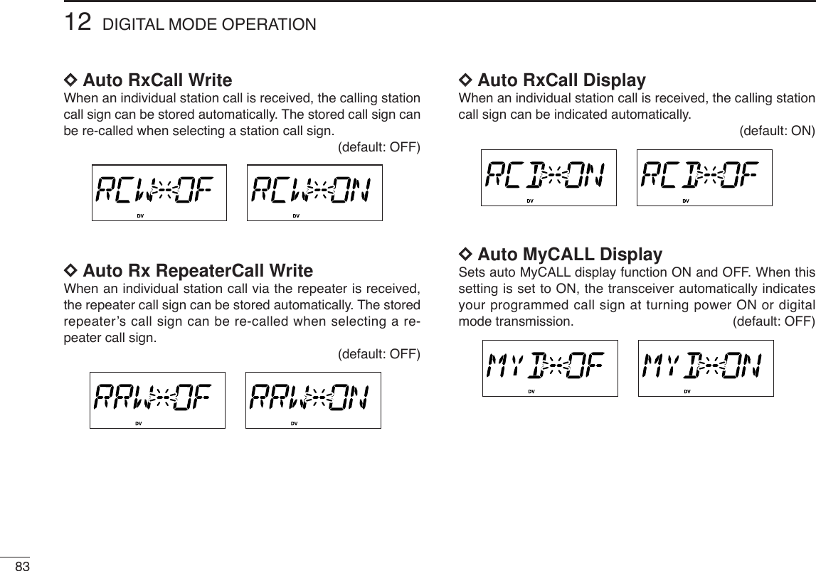
![7912 DIGITAL MODE OPERATION■When receiving a Digital callWhen an individual station call is received, the calling stationcall sign can be stored into the received call record.The record is cleared once turning power OFF.DDReceived call recordqPush [SET•LOCK]to enter call sign set mode.•Rotate [DIAL] to select “CALLS,” if “SET” or “MESSAG” is dis-played.wPush [SET•LOCK] or [S.MW•MW] several times to selectreceived call indication, then push [BAND].•“RXCALL,” “RXRPT1,” and “RXRPT2” are available for the re-ceived station call sign, repeater 1/2 call signs, respectively.wTo confirm the received call, push [BAND] to enter the re-ceived call sign indication mode.■Break-in communicationThe break-in function allows you to break into an another sta-tions communications in both Digital voice and slow data op-eration.qWhile receiving an another stations communication, push[SET• LOCK] to enter call sign set mode.•Rotate [DIAL] to select “CALLS,” if “SET” or “MESSAG” is dis-played.wPush [SET•LOCK] or [S.MW•MW] several times to selectreceived call indication, then set the either station/repeatercall sign into “MyCALL,” “UrCALL,” “RPT1 C” and “RPT2C.”ePush [TONE•T-SCAN] for 1 sec. to turn the break-in set-ting ON.•“BK” appears.rWhen both stations are in standby, transmit to send abreak-in call.•Programmed call sign station receives the break-in call as wellas your call sign.tWait for the reply call from the station who receive thebreak-in call.yAfter receive the reply call, communicate normal way.uTo cancel the break-in, push [TONE•T-SCAN] for 1 sec. toturn OFF.](https://usermanual.wiki/ICOM-orporated/278800.Users-Manual-Part-2/User-Guide-473909-Page-33.png)
![8012DIGITAL MODE OPERATION12345678910111213141516■EMR communicationThe EMR communication mode is available for Digital modesoperation. In the EMR call, no call sign setting is necessary.qSet the desired frequency then push and hold[MONI•DTMF] until 4 beep sound to turn the EMR settingON. •“EM” appears.wOperate the transceiver normal way.eTo cancel the EMR communication mode, push[MONI•DTMF] for 1 sec. to turn OFF.The digital code (CSQL) or call sign (DSQL) squelch opensonly when receiving a voice signal with the same pre-pro-grammed digital code or call sign, respectively. The digitalcode or call sign squelch does not function while in a slowdata communication.qSet the operating frequency.wProgram the digital code or call sign in setting mode.•See p. 69, “Digital code setting” or pgs. 59, 60 “Call sign programming.”ePush [TONE•T-SCAN] several times until “CSQL” or“DSQL” appears in the function display.•“CSQL” for digital code squelch; “DSQL” for call sign squelchoperation.rWhen a signal with the matched digital code/call sign is re-ceived, the squelch opens and the signal can be heard.•When the received signal includes an unmatched digitalcode/call sign, the squelch does not open. However, the S/RFindicator shows the received signal strength.•To open the squelch manually, push [MONI•DTMF] momentarily.tOperate the transceiver in the normal way (push [PTT] totransmit; release [PTT] to receive).yTo cancel the digital code/call sign squelch, push[TONE•T-SCAN] several times until “CSQL” or “DSQL”disappears.✔While scanning in digital mode:• The call sign squelch function deactivate, then after can-celling the scan it will activate again.• Scan stops near channel in a 5 kHz tuning steps, and thenno sound comes out.■Digital code/Call sign squelch operation](https://usermanual.wiki/ICOM-orporated/278800.Users-Manual-Part-2/User-Guide-473909-Page-34.png)
![8112 DIGITAL MODE OPERATION■Slow data communicationIn addition to the digital voice communication, a slow datacommunication is available (Refer p. 5 about the transceiver-PC connection details).qWhile pushing [SET•LOCK], push [PWR] for 1 sec. toenter initial set mode. (see p. 61)wPush [SET•LOCK] or [S.MW•MW] several times to selectthe data communication speed setting. (see p.64)•“SPD” appears.•Select suitable data speed for your PC or application.eSet the desired frequency.rSet another settings, such as repeater call, digital codesquelch, transmit output power.tPush [SET•LOCK] to enter set mode.•Rotate [DIAL] to select “SET,” if “CALLS” or “MESSAG” is dis-played.yPush [SET•LOCK] or [S.MW•MW] several times to selectthe automatic data transmission setting. (see p.82)•“DVT” appears.•Skip this setting, if you want to transmit manually.uStart up the slow data communication application.iSet the application as follows.•Port : The same COM port number as ID-800H’s•Baud rate : 4800 bps or 9600 bps (same as step w)•Data : 8 bit•Parity : None•Stop : 1 bit•Flow control : Xon/XoffoTransceiver automatically transmits or receive the datawhen you sending data to transceiver. Or push and hold[PTT] to transmit, release to receive the data manually.•Refer to the instruction of the application that how to send or re-ceive data.](https://usermanual.wiki/ICOM-orporated/278800.Users-Manual-Part-2/User-Guide-473909-Page-35.png)
![8212DIGITAL MODE OPERATION12345678910111213141516■Other setting itemsqDuring digital mode operation, push [SET•LOCK] to enterset mode.•Rotate [DIAL] to select “SET,” if “CALLS“ or “MESSAG” is dis-played.wPush [SET•LOCK] or [S.MW•MW] to select the desireditem.eRotate [DIAL] to select the desired value or condition.zDuring digital mode operation, push [SETB(D-OFF)] to enter set mode, then push [YY]or [ZZ]to select “SET” if necessary.xPush [SETB(D-OFF)] or [ENTC (T-OFF)]several times to select the desired item.cPush [YY]or [ZZ]to select the desired valueor condition.DDAuto ReplyDuring Digital mode operation, auto reply function is avail-able. This function replys to an individual station call even youare away from the transceiver. (default: OFF)After the manual transmission (pushing [PTT]), the AutoReply setting is return to OFF automatically. DDDigital CodeSets the desired digital code for digital code squelch opera-tion. Total of 100 codes (00–99) are available. (default: 00)DDAuto data TransmissionDuring slow data operation, auto data transmission functionis available. This function transmits when data are input fromPC via the [DATA] jack. (default: PTT)BANK/OPTION](https://usermanual.wiki/ICOM-orporated/278800.Users-Manual-Part-2/User-Guide-473909-Page-36.png)
![8412DIGITAL MODE OPERATION12345678910111213141516DDDigital MonitorSets the desired monitoring mode during digital mode opera-tion from “DI(Digital)” and “AN(Analog).” (default: DI)Select “ANALOG” when using FM mode for monitoring.DDMessage TransmissionSelect the Message transmission function ON and OFF.When ON is selected, transceiver transmits a text message(pre-programmed). (default: OFF) qPush [SET•LOCK] to enter message set mode.•Rotate [DIAL] to select “MESSAG,” if “CALLS” or “SET” is dis-played.wPush [SET•LOCK] or [S.MW•MW] several times to selectthe message transmission setting.•“TXM” appears.DDTX messageTX messages are available up to 6 channels and each chan-nel can be programmed up to 20 characters message. Avail-able characters are 0to 9, Ato Z(capital letters only), somesymbols and space. (shown below table)(3)(D)(N)(X)(+) (4)(E)(O)(Y)(–) (5)(F)(P)(Z)(✱)(6)(G)(Q)(/)(7)(H)(R)(,)(8)(I)(S)(space)(9)(T)(0)(A)(U)(1)(B)(V)(2)(C) (J) (K)(L)(M)(W)(.)( ))(( )(’)(&)(%)($)(#)(!)(<)(:) (;) (=) (>) (?)(@)([) (\) (]) (^)](https://usermanual.wiki/ICOM-orporated/278800.Users-Manual-Part-2/User-Guide-473909-Page-38.png)
![8512 DIGITAL MODE OPERATIONDDTX message programmingATX message channel C1 must be programmed, if you wantto use the GPS message. The GPS message is transmittedfrom channel C1 only.qPush [SET•LOCK] to enter message set mode.•Rotate [DIAL] to select “MESSAG,” if “CALLS” or “SET” is dis-played.wPush [SET•LOCK] or [S.MW•MW] several times until“TXM-C” appears, then push [BAND].eRotate [DIAL] to select the message channel.•One of either “C1” to “C6” flashes.rPush [BAND] to set into message programming condition.•The 1st digit blinks and channel indication stops blinking.tRotate [DIAL] to set the desired character.yPush [SET•LOCK] to select 2nd digit, then rotate [DIAL] toset the desired character.•2nd digit blinks (1st digit stop blinking).•Repeat this step for programming.uPush [BAND] to set the message.yRepeat steps wto yto set another message channels.uPush any key below the display to exit the message setmode.](https://usermanual.wiki/ICOM-orporated/278800.Users-Manual-Part-2/User-Guide-473909-Page-39.png)
![8612DIGITAL MODE OPERATION12345678910111213141516■GPS operationThe ID-800H can indicate the current position (Latitude andLongitude) when a GPS receiver (compatible with an RS-232C output/NMEA format/4800 bps) is connected to [DATA]jack. And also can transmit the position data and message toother stations.DDPosition indicationqWhile connecting a GPS receiver and operating digitalmode, push [SET•LOCK] to enter set mode.•Rotate [DIAL] to select “SET,” if “CALLS” or “MESSAG” is dis-played.wPush [SET•LOCK] or [S.MW•MW] several times to selectthe GPS setting.•“GPS” appears.eRotate [DIAL] to set the GPS setting ON, then push[BAND] to enter the sentence formatter set mode.rPush [SET•LOCK] or [S.MW•MW] several times to selectthe suitable sentence formatter for the connecting GPS re-ceiver.•For your position indication is necessary to set “GGA” or “RMC” isONtPush [BAND] to return to set mode.yPush [SET•LOCK] several times to select the position in-dication.uPush [BAND] to enter the position indication.•Latitude and longitude date appear in order as below.yAfter checking the current position, push any key below thedisplay to return to normal operating mode.](https://usermanual.wiki/ICOM-orporated/278800.Users-Manual-Part-2/User-Guide-473909-Page-40.png)
![8712 DIGITAL MODE OPERATIONDDGPS Automatic transmissionqWhile connecting a GPS receiver and operating digitalmode, push [SET•LOCK] to enter set mode.•Rotate [DIAL] to select “SET,” if “CALLS” or “MESSAG” is dis-played.wPush [SET•LOCK] or [S.MW•MW] several times to selectthe GPS automatic transmission.•“GTX” appears.eRotate [DIAL] to set the interval time for the GPS auto-matic transmission.•Interval time is selectable from 0.5 (30 sec.), 1, 3, 5, 10, 30 min.•When TX message channel “C1” is programmed, GPS transmis-sion automatically transmits TX message “C1.”rPush any key below the display to exit set mode.DDReceiving a GPS transmissionqPush [SET•LOCK] to enter set mode.•Rotate [DIAL] to select “SET,” if “CALLS” or “MESSAG” is dis-played.wPush [SET•LOCK] or [S.MW•MW] several times to selectthe received position.•“RX POS” appears.ePush [BAND] to enter the position indication.•Latitude data and longitude date appear alternately.rPush [BAND], then [SET•LOCK] to select the receivedGPS message.tPush [BAND] to enter the message.•Received message is indicated, push [SET•LOCK] or[S.MW•MW] to move the cursor to right or left, respectively.yAfter checking a received position and message, push anykey below the display to return to normal operating mode.](https://usermanual.wiki/ICOM-orporated/278800.Users-Manual-Part-2/User-Guide-473909-Page-41.png)