ICOM orporated 283300 UHF Transceiver User Manual
ICOM Incorporated UHF Transceiver Users Manual
UserManual.wiki
>
ICOM orporated
>
283300 User Manual
Users Manual
Navigation menu
Upload a User Manual
Namespaces
Wiki Guide
HTML
PDF
Info
Views
User Manual
Discussion / Help
Navigation
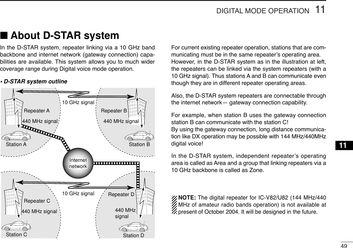
![vi8SCAN OPERATION............................................................ 28–31■Scan types ............................................................................ 28■Programmed scan................................................................. 28■Memory scan..........................................................................29■Skip channels........................................................................ 30■Priority watch......................................................................... 30■Scan resume condition.......................................................... 319SUBAUDIBLE TONES....................................................... 32–35■Tone squelch ......................................................................... 32■Pocket beep operation .......................................................... 34■Tone scan.............................................................................. 3510PAGER/CODE SQUELCH (Required Optional UT-108) .. 36–39■Pager function ....................................................................... 36■Code programming ............................................................... 36■Pager operation..................................................................... 38■Code squelch ........................................................................ 3911 DIGITAL MODE OPERATION(Required Optional UT-118)...............................................40–56■Digital mode operation .......................................................... 40■Call sign programming .......................................................... 40■Digital voice mode operation ................................................. 43■When receiving a Digital call ................................................. 44■Break-in communication ....................................................... 45■EMR communication ............................................................. 46■Pocket beep operation .......................................................... 46■Digital squelch functions ....................................................... 47■Digital monitor ....................................................................... 47■Low-speed data communication ........................................... 48■About D-STAR system .......................................................... 49■Repeater call sign programming ........................................... 50■Other setting items ................................................................ 51■GPS operation ...................................................................... 5512OTHER FUNCTIONS ......................................................... 57–67■SET MODE............................................................................ 57■INITIAL SET MODE .............................................................. 61■Weather channel operation (IC-V82 [USA] versions only) .... 66■CPU reset.............................................................................. 67■Partial reset ........................................................................... 6713CLONING ................................................................................. 6814OPTIONAL UNIT................................................................ 69–70■Optional UT-108/118 installation ........................................... 69■Optional MB-86 installation ................................................... 6915SPECIFICATIONS.................................................................... 71■IC-V82 ................................................................................... 71■IC-U82................................................................................... 7216OPTIONS.................................................................................. 7317CE.............................................................................................7512345678910111213141516](https://usermanual.wiki/ICOM-orporated/283300/User-Guide-490696-Page-7.png)
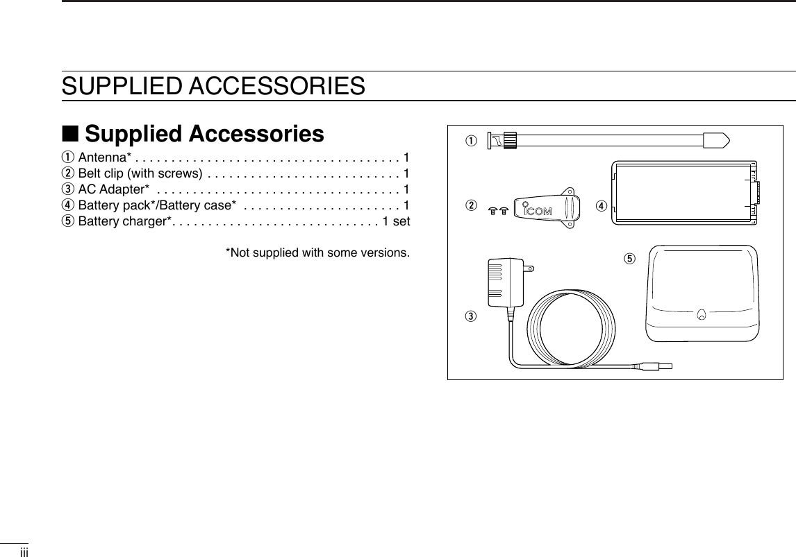
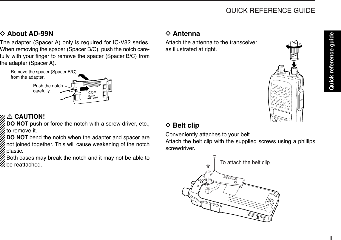
![IQUICK REFERENCE GUIDE■PreparationDBattery pack replacementBefore replacing the battery pack, push [PWR] for 1 sec. toturn the power OFF.•Slide the battery release forward, then pull the battery pack upwardwith the transceiver facing away from you.DBattery case— optional for some versionsWhen using a BP-208N BATTERY CASEattached to the trans-ceiver, install 6 AA (LR6) size alkaline batteries as illustratedbelow.DCharging with the BC-144N/146The optional BC-144N provides rapid charging, and the BC-146 provides regular charging of an optional battery packwith/without transceiver. The following is additionally required:• An optional AC adapter. (An AD-99N is supplied with BC-144N orBC-146.)Check orientation for correct charg-ing. (Insert together with AD-99N.)Turn power OFF.BC-144N/146 +AD-99N](https://usermanual.wiki/ICOM-orporated/283300/User-Guide-490696-Page-8.png)
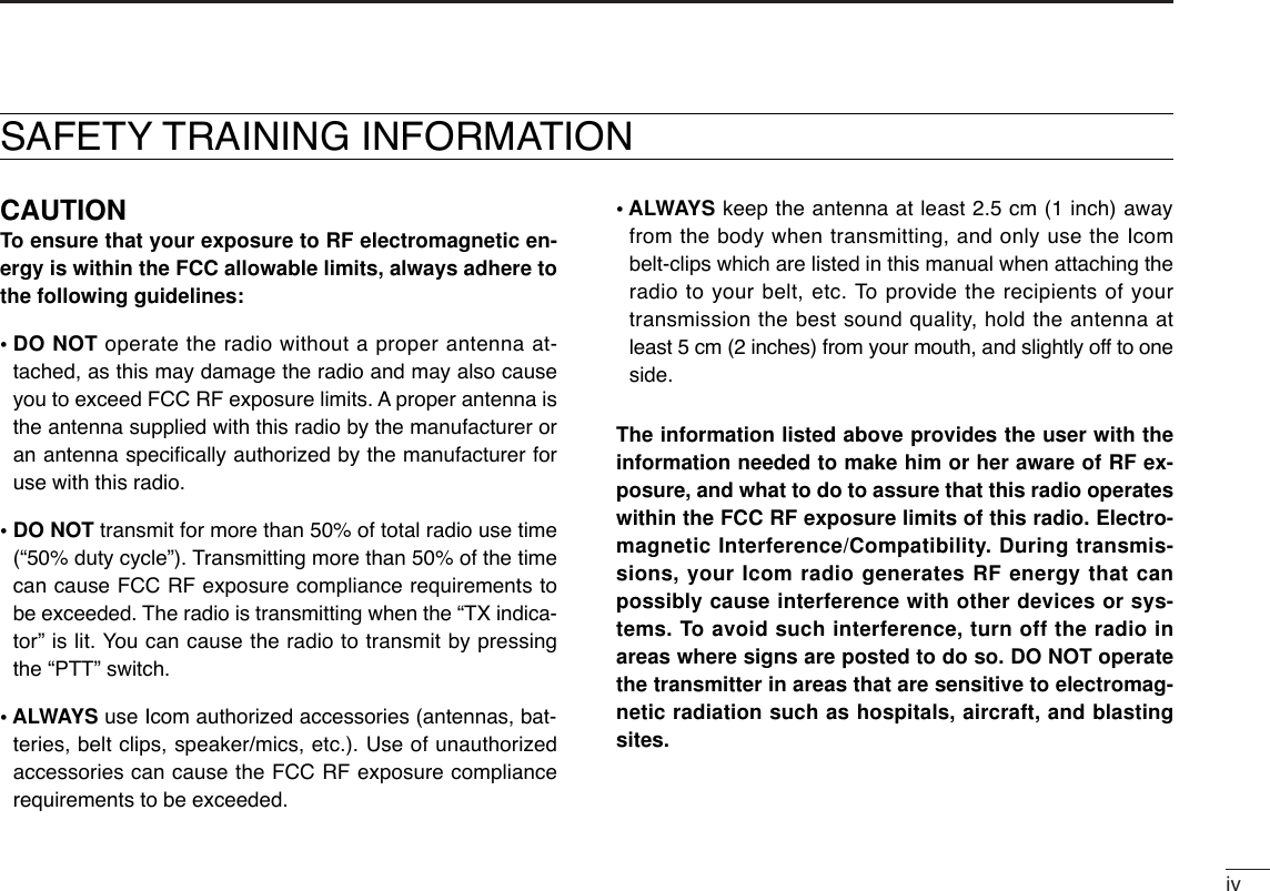
![IIIQUICK REFERENCE GUIDE■Your first contactNow that you have your IC-V82/U82 ready, you are exited toget on the air. We would like to walk you through a few basicoperational steps to make your first “On The Air” use an en-joyable experience.DAbout default settingThe [VOL] control function can be traded with [YY]/[ZZ]keys func-tion in INITIAL SET MODE. However, in this QUICK REFERENCE,the factory default setting ([VOL] controls audio output level) isused for simple instructions.DBasic operation1. Turning ON the transceiverAlthough you have purchased a brand new transceiver, somesettings may be changed from the factory defaults becauseof the QC process. Resetting the CPU is necessary to startfrom factory default.➥While pushing [MONI] and[D•CLR], push [PWR] for 1 sec. toreset the CPU and turn power ON.2. Adjusting audio output level➥Rotate [VOL] to set the desiredaudio level.3. Adjusting the squelch level➥While pushing and holding[MONI], push [YY]or [ZZ]to set thesquelch level.4. Tune the desired frequencyThe up/down keys, [YY]/[ZZ], willallow you to tune the frequency thatyou want to operate on. Page 14 willinstruct you on how to adjust the tun-ing step.➥Push [YY]or [ZZ]to adjust the fre-quency.PWRMONICLRDMONI[VOL]](https://usermanual.wiki/ICOM-orporated/283300/User-Guide-490696-Page-10.png)
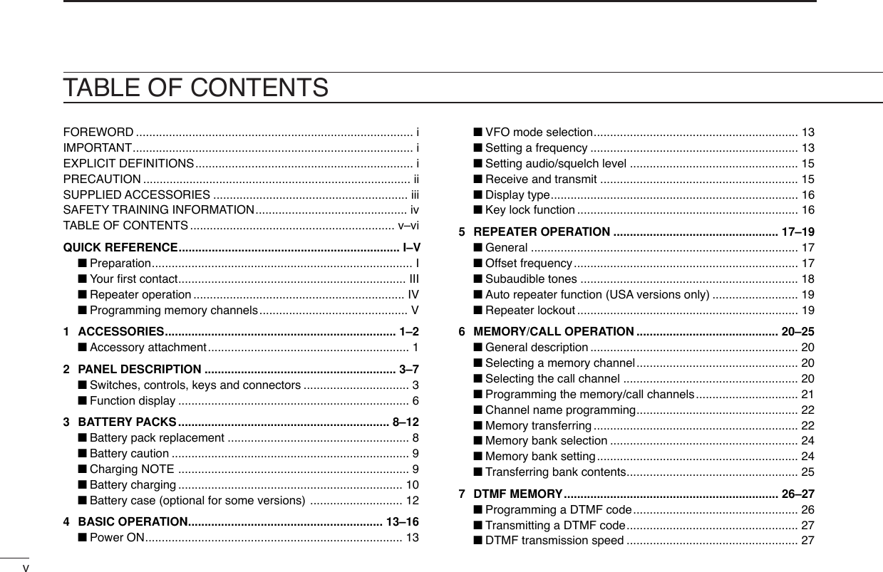
![IVQUICK REFERENCE GUIDEDirect frequency input from the key-pad is also available. ➥To enter the desired frequency,enter 6-digits starting from the100 MHz digit.•Enter three* to five digits then push-ing [✱•ENT]is also set the fre-quency. (*Some versions areavailable from two digits.)•When a digit is mistakenly input,push [D.CLR]to abort to input.5. Transmit and receive ➥Push and hold [PTT] to transmit, then speak into the mi-crophone; release to receive.■Repeater operation1. Setting duplex➥Push [A•FUNC], then [4•DUP]sev-eral times to select minus duplexor plus duplex.•The USA version has an auto re-peater function, therefore, setting du-plex is not required.2. Repeater tone➥Push [A•FUNC], then [1•TONE]several times until “ ” appears, ifrequired.TONE1FUNCADUP4FUNCA• Example 1— when entering 145.525 MHzPush• Example 2— when entering 144.800 MHzP.BEEP2DUP4DUPTONE41SCAN5SCAN5SCAN5PushDUPTONE41OPT0SET8ENTCLRDKeypadENTQuick reference guide](https://usermanual.wiki/ICOM-orporated/283300/User-Guide-490696-Page-11.png)
![VQUICK REFERENCE GUIDEThe IC-V82/U82 has a total of 207 memory channels (includ-ing 6 scan edges and 1 call channel) for storing often usedoperating frequency, repeater settings, etc.1. Setting frequencyIn VFO mode, set the desired operating frequency with otherdesired settings, such as repeater and subaudible tone.2. Selecting a memory channel➥Push [A•FUNC], [C•MR]then push[YY] or [ZZ]several times to selectthe desired memory channel.•“X” indicator and memory channelnumber blink.3. Writing a memory channel➥Push [A•FUNC], then push [C•MR]for 1 sec. to program.•3 beeps sound•Continue to hold [C•MR]down for 1 sec. after 3 beeps are emit-ted, to increment the displayed memory channel number.MRCFUNCAMRCFUNCA■Programming memory channels](https://usermanual.wiki/ICOM-orporated/283300/User-Guide-490696-Page-12.png)
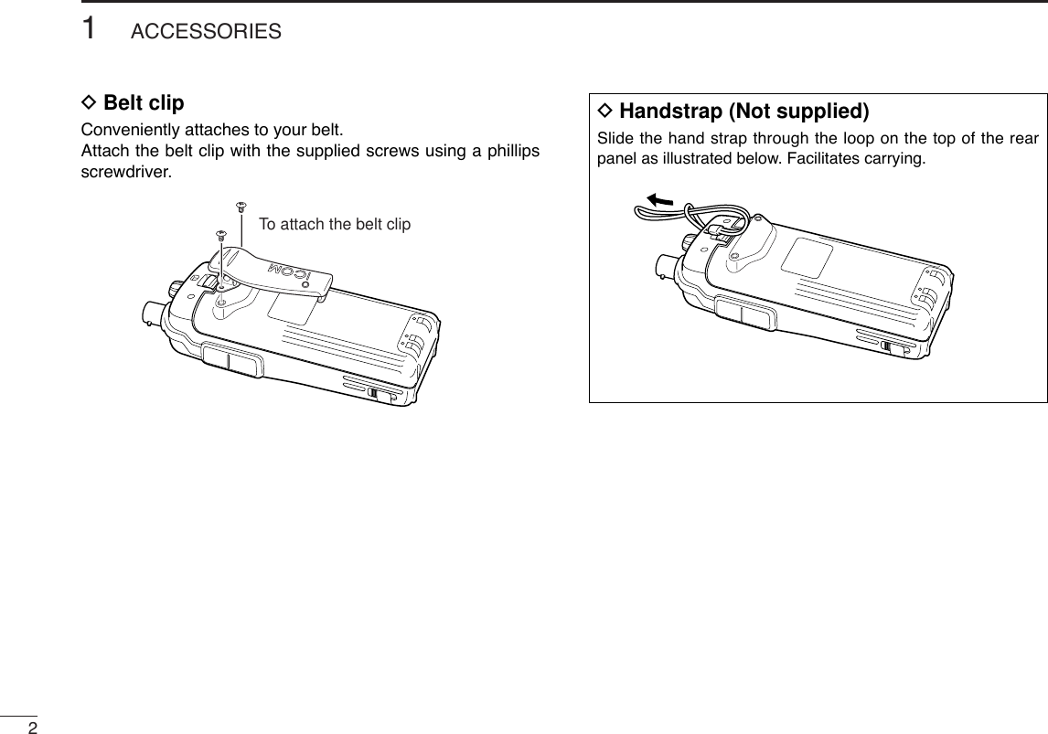
![11ACCESSORIES1■Accessory attachmentDAntennaAttach the antenna to the transceiver as illustrated below. Keep the [SP/MIC] cap (SP/MIC jack cover) attached whenjacks are not in use to avoid bad contacts.Attach the[SP/MIC] cap.[SP/MIC] cap](https://usermanual.wiki/ICOM-orporated/283300/User-Guide-490696-Page-13.png)
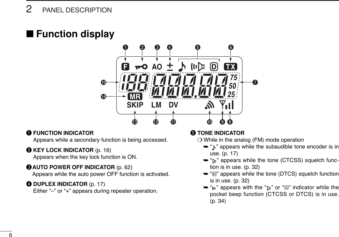
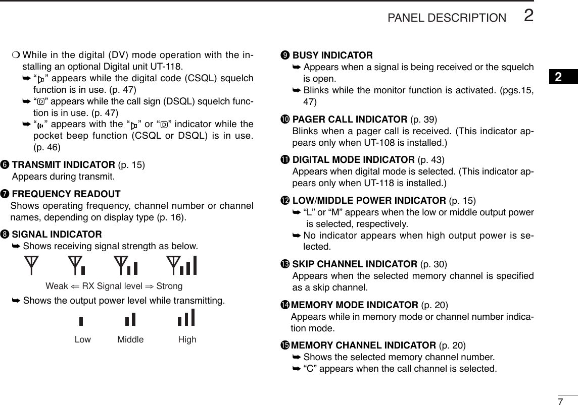
![32PANEL DESCRIPTION12qCONTROL DIAL [VOL]*Rotate to adjust the volume level.wPTT SWITCH [PTT]Push and hold to transmit; release to receive.eUP/DOWN KEYS [YY]/[ZZ]*Selects the operating frequency.rKEY PAD (pgs. 4, 5) Used to enter operating frequency, the DTMF codes, etc.tANTENNA CONNECTORConnects the supplied antenna.y[SP]/[MIC] JACKConnect an optional speaker-microphone or headset, if de-sired. The internal microphone and speaker will not func-tion when either is connected.uFUNCTION DISPLAY (pgs 6, 7)iSQUELCH/MONITOR SWITCH [MONI]Push and hold to force the squelch open and set the trans-ceiver to the squelch level adjustable condition.oPOWER SWITCH [PWR]Push for 1 sec. to turn the power ON and OFF.MONICALLDUP SCANPRIOENTSETH/M/LOPTSKIPBANKTONET.SCANP.BEEPMR CLRFUNCPWR9874123AB DC560qwtMicrophoneSpeakery!0ouier■Switches, controls, keys and connectors*The assigned function for [VOL] and [YY]/[ZZ]can betraded in INITIAL SET MODE(pgs. 14, 63).](https://usermanual.wiki/ICOM-orporated/283300/User-Guide-490696-Page-15.png)
![42PANEL DESCRIPTION!0 [DATA] JACKConnect to a PC or GPS receiver via the RS232C cable (D-sub 9 pin) for data communication in the RS-232C format.DKey pad[A•FUNC]Access to secondary function.[B•CALL]Select the call channel. (p. 20)[C•MR]➥Selects a memory mode. (p. 20)➥After pushing [A•FUNC], entering into memoryprogramming/editing mode. (pgs. 21–23)➥After pushing [A•FUNC], programs/transfersVFO/memory or call channel contents intomemory channel/VFO when pushed for 1 sec.(pgs. 21–23)[D•CLR]Selects VFO mode, aborts direct frequency input,or cancels scanning, etc. (pgs. 13, 28)[1•TONE]➥Input digit “1” during frequency input, memorychannel selection, etc. (pgs. 13, 20)➥After pushing [A•FUNC], selects the subaudibletone function. (pgs. 17, 32)[2•P.BEEP]➥Input digit “2” during frequency input, memorychannel selection, etc. (pgs. 13, 20)➥After pushing [A•FUNC], turn the pocket beepfunction ON and OFF. (p. 34)P.BEEP2TONE1CLRDMRCCALLBFUNCAPin 2 (RxD), Pin 3 (TxD), Pin 5 (GND)to [DATA] jackTxD2.5(d) mm Less than10(d) mmGNDRxD1569RS-232C(DB-9 female)Make sure the connection between transceiver and PC, oth-erwise misreading may occur for data communication.](https://usermanual.wiki/ICOM-orporated/283300/User-Guide-490696-Page-16.png)
![52PANEL DESCRIPTION2[3•T.SCAN]➥Input digit “3” during frequency input, memorychannel selection, etc. (pgs. 13, 20)➥After pushing [A•FUNC], starts the tone scan-ning. (pgs. 18, 35)[4•DUP]➥Input digit “4” during frequency input, memorychannel selection, etc. (pgs. 13, 20)➥After pushing [A•FUNC], selects a duplex func-tion (–duplex, +duplex, simplex). (p. 17)[5•SCAN]➥Input digit “5” during frequency input, memorychannel selection, etc. (pgs. 13, 20)➥After pushing [A•FUNC], starts scanning. (p. 28)[6•SKIP]➥Input digit “6” during frequency input, memorychannel selection, etc. (pgs. 13, 20)➥After pushing [A•FUNC], sets and cancels skipsetting for memory skip scan during memorymode. (p. 30)[7•PRIO]➥Input digit “7” during frequency input, memorychannel selection, etc. (pgs. 13, 20)➥After pushing [A•FUNC], starts the prioritywatch. (p. 30)[8•SET]➥Input digit “8” during frequency input, memorychannel selection, etc. (pgs. 13, 20)➥After pushing [A•FUNC], enters into SET MODE.(p. 57)[9•H/M/L]➥Input digit “9” during frequency input, memorychannel selection, etc. (pgs. 13, 20)➥After pushing [A•FUNC], switches transmitpower from high, middle and low output power.(p. 15)[0•OPT]➥Input digit “0” during frequency input, memorychannel selection, etc. (pgs. 13, 20)➥After pushing [A•FUNC], selects an optionalfunction mode, such as pager, code squelch ordigital operation. (pgs. 38, 40)[#•BANK]After pushing [A•FUNC], enters a memory bankcondition. (p. 24)[✱•ENT]➥Sets the frequency even if the full 6-digits offrequency have not been entered. (p. 13)➥After pushing [A•FUNC], switches key lock func-tion ON and OFF when pushed for 1 sec. Lockall keys, except [PWR], [PTT], [MONI] andaudio level adjustment. (p. 16)ENTBANKOPT0H/M/L9SET8PRIO7SKIP6SCAN5DUP4T.SCAN3](https://usermanual.wiki/ICOM-orporated/283300/User-Guide-490696-Page-17.png)
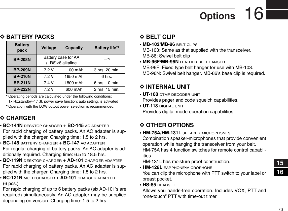
![■Battery pack replacement➥Before replacing the batterypack, push [PWR] for 1 sec.to turn the power OFF.➥Slide the battery release forward, then pull the battery packupward with the transceiver facing away from you.DDBATTERY PACKS*1Operating periods are calculated under the following conditions;Tx : Rx : standby =1 : 1 : 8, power save function: auto setting isactivated*2Operating period depends on the alkaline cells used. Battery Voltage Capacity Battery life*1packBP-208N Battery case for AA —*2(LR6)×6 alkalineBP-209N 7.2 V 1100 mAh 3 hrs. 20 min.BP-210N 7.2 V 1650 mAh 6 hrs.BP-211N 7.4 V 1800 mAh 6 hrs. 10 min.BP-222N 7.2 V 600 mAh 2 hrs. 15 min.Push for 1 sec.PWR8BATTERY PACKS3](https://usermanual.wiki/ICOM-orporated/283300/User-Guide-490696-Page-20.png)
![134BASIC OPERATION34■Power ON➥Push [PWR] for 1 sec. to turnpower ON.■VFO mode selectionThe transceiver has 2 basic oper-ating modes: VFO mode andmemory mode.➥Push [D•CLR]to select VFOmode.■Setting a frequencyDVia the keypadqPush [D•CLR]to select VFO mode, if necessary.wTo enter the desired frequency, enter 6-digits starting fromthe 100 MHz digit.•Enter three* to five digits then pushing [✱•ENT]is also set thefrequency. (*Some versions are available from two digits.)•When a digit is mistakenly input, push [D.CLR]to abort to input.• Example 1— when entering 145.525 MHzPush• Example 2— when entering 144.800 MHzP.BEEP2DUP4DUPTONE41SCAN5SCAN5SCAN5PushDUPTONE41OPT0SET8ENTCLRDPush for 1 sec.PWR](https://usermanual.wiki/ICOM-orporated/283300/User-Guide-490696-Page-25.png)
![DBy other methodsVia the [YY]/[ZZ] keys➥Push [YY]or [ZZ]several times to set the desired frequency.•Each push increases/decreases the frequency by the selectedtuning step. See right content for tuning step details.DTuning step selectionThe IC-V82/U82 has 8 tuningsteps— 5, 10, 12.5, 15, 20, 25, 30and 50 kHz. The tuning step is selec-table in SET MODE. qPush [A•FUNC]then [8•SET]toenter SET MODE.wPush [YY]or [ZZ]several times toselect the tuning step item.eRotate [VOL] to select the desired tuning step.rPush [✱•ENT]to exit SET MODE.[VOL]ENTFUNCASET8144BASIC OPERATION✔For your information— [VOL] function assignmentThe [VOL] control can be used asa tuning dial for frequency tuninginstead of [YY]/[ZZ]keys. However,while [VOL] functions as tuningdial, [YY]/[ZZ]keys functions as AFvolume control.qWhile pushing [YY]and [ZZ], turnpower ON to enter INITIAL SETMODE. wPush [YY]or [ZZ]several times toselect the dial assignment item, “tOP.”eRotate [VOL] to select the condition.rTo exit SET MODE, push [✱•ENT].[VOL] is assigned as AF volume control. [VOL] is assigned as tuning dial.[VOL]ENTPWR](https://usermanual.wiki/ICOM-orporated/283300/User-Guide-490696-Page-26.png)
![154BASIC OPERATION4■Setting audio/squelch levelDTo set the audio levelRotate [VOL] to set the desiredaudio level while receiving a sig-nal.• When no signal is received, pushand hold [MONI] while setting theaudio level. • When [VOL] is assigned as tuningdial, push [YY]/[ZZ]to adjust the audiooutput level. (pgs. 14, 63)DTo set the squelch levelWhile pushing [MONI], push[YY]/[ZZ]to set the squelch level.• The squelch level “1” is loosesquelch, “10” is tight squelch.• When [VOL] is assigned as tuningdial, rotate [VOL] while [MONI] ispushed. (pgs. 14, 63)■Receive and transmitqPush [PWR] for 1 sec. to turn the power ON.wAdjust audio volume to the desired level.eSet a frequency.When a signal is received:• Squelch opens and audio is emitted from the speaker.• Signal indicator shows the relative signal strength level.rPush [A•FUNC], then [9•H/M/L]to select output power be-tween high, middle and low.•“L” appears when low power is selected.•“M” appears when middle power is selected.•No indication appears when high power is selected.tPush and hold [PTT] to transmit, then speak into the micro-phone.• “$” appears.•Do not hold the microphone too close to your mouth orspeak too loudly. This may distort the signal.yRelease [PTT] to receive. ✔For your information— Monitor function:Push and hold [MONI] to listen to weak signals that do notopen the squelch.MONI[VOL]](https://usermanual.wiki/ICOM-orporated/283300/User-Guide-490696-Page-27.png)
![164BASIC OPERATION■Display type The transceiver has 3 display types to suit your operatingstyle.The display type is selected in INITIAL SET MODE(p. 63).“Frequency Indication” typeDisplays operating frequency.“Channel Number Indication” typeDisplays memory channel number. In this type only pre-programmed memory channel numbers are displayed. VFO mode cannot be selected.• When the channel indication type is selected, only the followingfunctions can be performed.- Scan function (p. 28)- Output power setting (p. 15)- DTMF memory function (p. 26)- Key lock function (see right content)- Scan pause timer setting, function key timer setting and LCDbacklight setting in SET MODE(p. 59)“Channel Name Indication” typeDisplays memory channel name you have assigned. In thisdisplay pre-programmed memory channel names are dis-played. VFO mode is selectable.• Programmed frequencies are indicated pre-programmed in theselected memory channel.• Push and hold [MONI] to display the operating frequency.■Key lock functionThe key lock function prevents accidental frequency changesand function activation.Push [A•FUNC]then push [✱•ENT]for 1 sec. to toggle the function ON andOFF.•“ ” appears while the lock function isactivated.•[PWR], [PTT], [VOL] and [MONI] canbe operated regardless of this setting.USINGINITIAL SET MODEFUNCAENT](https://usermanual.wiki/ICOM-orporated/283300/User-Guide-490696-Page-28.png)
![175REPEATER OPERATION45■GeneralWhen using a repeater, the transmit frequency is shifted fromthe receive frequency by the offset frequency. It is convenientto program repeater information into memory channels.qSet the receive frequency (repeater output frequency).wPush [A•FUNC]and [4•DUP]several times to select “–” or“+.”•“–” indicates the transmit frequency is shifted down; “+” indicatesthe transmit frequency is shifted up.• Blinking “–” or “+” indicates the reversed duplex mode is selectedin SET MODE(p. 58).ePush [A•FUNC]and [1•TONE]several times to activate thesubaudible tone encoder, if required.•“ ” appears.•Select the desired subaudible tone frequency, if necessary. (p. 18)rPush and hold [PTT] to transmit.•The displayed frequency automatically changes to the transmitfrequency (repeater input frequency).•If “OFF” appears, check the offset frequency (see right contentfor details) and direction.tRelease [PTT] to receive.yPush and hold [MONI] to check whether the other station’stransmit signal can be directly received or not.About reversed duplex modeWhen the reversed duplex mode is selected, the receive fre-quency shifts. (Transmit frequency shifts in normal duplexmode.)Each receive and transmit frequency is shown in the tablebelow with the following conditions;IC-V82: Input freq.-145.30 MHz, Direction-negative, Offset frequency-0.6 MHzIC-U82: Input freq.-439.80 MHz, Direction-negative, Offset frequency-5 MHz■Offset frequencyWhen communicating through a repeater, the transmit fre-quency is shifted from the receive frequency by an amountdetermined by the offset frequency.qPush [A•FUNC], then push [8•SET]to enter SET MODE.wPush [YY]or [ZZ]several times until “±” and offset frequencyappear.eRotate [VOL] to select the desired offset frequency.•Selectable steps are the same as the pre-set tuning steps.•The unit of the displayed offset frequency is “MHz.”rPush [✱•ENT](or [D•CLR]) to fix the offset frequency andexit SET MODE.USINGSET MODEIC-V82 IC-U82Reversed OFF ON OFF ONRx freq. 145.30 MHz 144.70 MHz 439.80 MHz 434.80 MHzTx freq. 144.70 MHz 145.30 MHz 434.80 MHz 439.80 MHz](https://usermanual.wiki/ICOM-orporated/283300/User-Guide-490696-Page-29.png)
![■Subaudible tonesSome repeaters require subaudible tones to be accessed.Subaudible tones are superimposed over your normal signaland must be set in advance.qPush [A•FUNC], then push [8•SET]to enter SET MODE.wPush [YY]or [ZZ]one or more times until “rt” appears.eRotate [VOL] to select the desired subaudible tone.rPush [✱•ENT](or [D•CLR]) to fix the selected tone andexit SET MODE.• Available subaudible tone frequencies (unit: Hz)DDTone informationSome repeaters require another tone system to be accessed. DTMF TONESWhile pushing [PTT], push the desired DTMF keys (0–9,[A•FUNC], [B•CALL], [C•MR], [D•CLR], [#•BANK]and[✱•ENT]) to transmit DTMF tones.•[✱•ENT]transmits as “E”, [#•BANK]transmits as “F.”•The transceiver has 16 DTMF memory channels (p. 26).1750 Hz TONEWhile pushing [PTT], push [YY]or [ZZ]to transmit a 1750 Hztone signal.✔ConvenientTone scan function: When you don’t know the subaudibletone used for a repeater, the tone scan is convenient for de-tecting the tone frequency.Push [A•FUNC], then push [3•T.SCAN]to start the tone scan.• Push [D•CLR]to cancel the scan.• When the required tone frequency is detected, the scanpauses.67.069.371.974.477.085.488.591.594.897.4100.0103.579.782.5107.2110.9114.8118.8123.0127.3131.8136.5141.3146.2151.4156.7159.8162.2165.5167.9171.3173.8177.3179.9183.5186.2189.9192.8196.6199.5203.5206.5210.7218.1225.7229.1233.6241.8250.3254.1USINGSET MODE185REPEATER OPERATION](https://usermanual.wiki/ICOM-orporated/283300/User-Guide-490696-Page-30.png)
![195REPEATER OPERATION■Auto repeater function(USA version only)The USA version automatically activates the repeater settings(duplex, ON/OFF, duplex direction, tone encoder ON/OFF)when the operating frequency falls within or outside of thegeneral repeater output frequency range. The offset and re-peater tone frequencies are not changed by the auto repeaterfunction. Reset these frequencies, if necessary.qWhile pushing [YY]and [ZZ], turn the power ON to enter INI-TIAL SET MODE.wPush [YY]or [ZZ]several times until “RPt” appears.eRotate [VOL] to select the desired condition.•“OF”— the auto repeater function is turned OFF;•“R1”— the auto repeater function activates for duplex only;•“R2”— the auto repeater function activates for duplex and tone.rPush [✱•ENT](or [D•CLR]) to exit INITIAL SET MODE.• Frequency range and offset direction■Repeater lockoutThis function helps prevent interference to other stations byinhibiting your transmission when a signal is received. Thetransceiver has two inhibiting conditions, repeater and busy.qWhile pushing [YY]and [ZZ], turn the power ON to enter INI-TIAL SET MODE.wPush [YY]or [ZZ]several times until “RLO” appears.eRotate [VOL] to turn the repeater lockout function to “RP,”“bU” or OFF.•“RP”: Transmit is inhibited when a signal with un-matched sub-audible tone is received.•“bU”: Transmit is inhibited when a signal is received.rPush [✱•ENT](or [D•CLR]) to exit INITIAL SET MODE.USINGINITIAL SET MODEUSINGINITIAL SET MODEFrequency range Duplex direction145.200–145.495 MHz “–” appears146.610–146.995 MHz147.000–147.395 MHz “+” appears442.000–444.995 MHz “+” appears447.000–449.995 MHz “–” appears5](https://usermanual.wiki/ICOM-orporated/283300/User-Guide-490696-Page-31.png)
![20MEMORY/CALL OPERATION6■General descriptionThe transceiver has 207 memory channels including 6 scanedge memory channels (3 pairs), and 1 call channel. Each ofthese channels can be individually programmed with operat-ing frequency (pgs. 13, 14), duplex direction (p. 17) and offset(p. 17), subaudible tone encoder or tone squelch and its tonefrequency (pgs. 18, 33) and skip information* (p. 30). In addition, a total of 10 memory banks, A to J, are availablefor usage by group, etc.*except for scan edge memory channels.■Selecting a memory channelqPush [C•MR]to select memory mode.•“X” appears.wEnter 2 digits to select the desired memory channel (orpush the [YY]/[ZZ]keys).•The memory channels 0–9 are proceeded by a “0.”• When [VOL] is assigned as tuning dial, rotate [VOL] to selectthe memory channel. (pgs. 14, 63)■Selecting the call channel➥Push [B•CALL]to select the call channel.•“C” is displayed instead of the memory channel number.•Push [D•CLR]or [C•MR]to select VFO or memory mode, respec-tively.Push“C” appearsCALLBTONEP.BEEP12PushMRCPush](https://usermanual.wiki/ICOM-orporated/283300/User-Guide-490696-Page-32.png)
![qPush [D•CLR]to select VFO mode, if necessary.wSet the desired frequency.eSet other information, such as tone, duplex, as desired.rPush [A•FUNC], then [C•MR]momentarily.•“X” and memory channel number blink.tPush [YY]or [ZZ]to select the desired memory channel.• When programming the call channel, select “C.”• When [VOL] is assigned as tuning dial, rotate [VOL] to selectthe memory channel. (pgs. 14, 63)yPush [A•FUNC], then push [C•MR]for 1 sec. (until 3 beepsare emitted) to program the information into the selectedmemory channel and return to VFO. •Continue to hold [C•MR]down for 1 sec. after 3 beeps are emit-ted, to increment the displayed memory channel number.MONICALLDUP SCANPRIOENTSETH/M/LOPTSKIPBANKTONET.SCANP.BE EPMR CLRFUNCPWR9874123AB DC560MONICALLDUP SCANPRIOENTSETH/M/LOPTSKIPBANKTONET.SCANP.BEEPMR CLRFUNCPWR9874123AB DC560MRFUNCACMONICALLDUP SCANPRIOENTSETH/M/LOPTSKIPBANKTONET.SCANP.BEEPMR CLRFUNCPWR9874123AB DC560MONICALLDUP SCANPRIOENTSETH/M/LOPTSKIPBANKTONET.SCANP.BE EPMR CLRFUNCPWR9874123AB DC560MRFUNCAC216MEMORY/CALL OPERATION6■Programming the memory/call channels](https://usermanual.wiki/ICOM-orporated/283300/User-Guide-490696-Page-33.png)
![■Channel name programming qSelect a “Channel Name Indication” type in INITIAL SETMODE(p. 63).wPush [C•MR]to select memorymode, if necessary.ePush [A•FUNC], then push [8•SET]to enter into the channel nameprogramming mode.• The character to be edited blinks.rRotate [VOL] to select a charac-ter.tPush [YY]to move to the right, [ZZ]to move to the left.• Up to 5 characters can be used for channel name.• Usable characters are A–Z, 0–9, “space,” +, –, =, ✱, /, [, ] and :.yPush [✱•ENT](or [D•CLR]) to fix and exit the channelname programming mode.■Memory transferringThis function transfers a memory channel’s contents to VFO(or another memory/call channel). This is useful when search-ing for signals around a memory channel frequency and forrecalling the offset frequency, subaudible tone frequency etc.DMemory/call ➾VFOqSelect the memory (call) channelto be transferred:➥Push [C•MR]or [B•CALL]to se-lect memory (call) mode.➥Push [YY]or [ZZ]to select thememory channel.• When [VOL] is assigned as tuningdial, rotate [VOL] to select thememory channel. (pgs. 14, 63)wPush [A•FUNC], then push [C•MR]for 1 sec. to transfer the selectedmemory contents to the VFO.•VFO mode is selected automatically.226MEMORY/CALL OPERATIONFUNCAMRCCALLBFUNCAMRCSET8[VOL]ENT](https://usermanual.wiki/ICOM-orporated/283300/User-Guide-490696-Page-34.png)
![DMemory/call ➾call/memoryqSelect the memory (call) channelto be transferred:➥Push [C•MR]or [B•CALL]to se-lect the memory (call) mode.➥Push [YY]or [ZZ]to select thememory channel.• When [VOL] is assigned as tuningdial, rotate [VOL] to select thememory channel. (pgs. 14, 63)wPush [A•FUNC], then push [C•MR]momentarily.•“--” and “X” blink.ePush [YY]or [ZZ]to select the target memory.• When [VOL] is assigned as tuning dial, rotate [VOL] to selectthe target channel. (pgs. 14, 63)rPush [A•FUNC], then push [C•MR]for 1 sec.•Memory mode is selected and the contents are transferred to thetarget memory.DClearing a memoryqPush [A•FUNC], then push [C•MR]to enter the memory transfermode.•“X” and a memory channel num-ber blink.wPush [YY]or [ZZ]to select thememory channel to be cleared.• When [VOL] is assigned as tuningdial, rotate [VOL] to select the mem-ory channel. (pgs. 14, 63)•The call channel cannot be cleared.ePerform the following operation within 1.5 sec, otherwisethe memory clearing is cancelled and the transceiver re-turns to the memory mode.- Push [A•FUNC], then push [C•MR]momentarily.- Push [A•FUNC], then push [C•MR]for 1 sec. •The contents of the selected memory are cleared.rPush [D•CLR]to return to regular operation.236MEMORY/CALL OPERATIONFUNCAMRCCALLBFUNCAMRC6](https://usermanual.wiki/ICOM-orporated/283300/User-Guide-490696-Page-35.png)
![246MEMORY/CALL OPERATION■Memory bank selectionThe IC-V82/U82 has a total of 10 banks (A to J). Regularmemory channels, 0 to 199, are assigned into the desiredbank for easy memory management. qPush [C•MR]to select memory mode.wPush [A•FUNC]and [#•BANK]to se-lect memory bank condition.•Bank initial blinks.eRotate [VOL] to select the desiredbank, A to J.•Banks that have no programmed con-tents are skipped.rPush [✱•ENT](or [D•CLR]) to setthe bank.•Initial stops blinking.tPush [YY]or [ZZ]to select the contents in the bank.•No channel numbers are displayed for memory bank operation.yTo return to regular memory condition, push [A•FUNC]and[#•BANK]to enter memory bank condition, then push[✱•ENT](or [D•CLR]).■Memory bank settingqPush [C•MR]to select memory mode, then select the de-sired memory channel via [YY]or [ZZ].wPush [A•FUNC]and [8•SET]to enterSET MODE.ePush [YY]or [ZZ]several times until“bAk” appears.•“– –” indication blinks as follows.rRotate [VOL] to select the desiredbank to be set.tPush [✱•ENT](or [D•CLR]) to set the channel into thebank and return to regular memory condition.yRepeat steps qto tto set another memory channel intothe same or another bank.[VOL]ENTFUNCASET8MRCPush[VOL]ENTFUNCABANKMRCPush](https://usermanual.wiki/ICOM-orporated/283300/User-Guide-490696-Page-36.png)
![256MEMORY/CALL OPERATION6■Transferring bank contentsContents of programmed memory banks can be cleared ortransferred to another bank.INFORMATION: Even if the memory bank contents arecleared, the memory channel contents still remain pro-grammed.qSelect the desired bank contents to be transferred or erased.➥Push [C•MR]to select memory mode.➥Push [A•FUNC]and [#•BANK], thenrotate [VOL] to select the desiredmemory bank.•Bank initial blinks.➥Push [✱•ENT](or [D•CLR]) toselect the bank then push [YY]and[ZZ]to select the desired contents.•Bank initial stops blinking.wPush [A•FUNC]and [8•SET]to enterSET MODE.ePush [YY]or [ZZ]several times until“bAk” appears.•Bank initial appears.rRotate [VOL] to select the desiredbank initial to transfer or erase.•Select “– –” indication when erasing thecontents from the bank.tPush [✱•ENT](or [D•CLR]) to transfer or erase, and re-turn to regular memory condition.yRepeat steps qto tfor transferring or erasing an an-other banks contents.[VOL]ENTFUNCASET8[VOL]ENTFUNCABANK](https://usermanual.wiki/ICOM-orporated/283300/User-Guide-490696-Page-37.png)
![26DTMF MEMORY7■Programming a DTMF codeThe transceiver has 16 DTMF memory channels (d0 to dF)for storage of often-used DTMF codes of up to 24 digits.qPush [A•FUNC], then push [0•OPT]to enter OPTION SETMODE.•Rotate [VOL] to select “dtm.OF,” if necessary.wPush [0•OPT]for 1 sec. to enter the DTMF memory.•One of “d0” to “dF” appears.eRotate [VOL] to select the desired channel.rPush [0•OPT]for 1 sec. to enter the DTMF programmingmode.•“_____” appears.•Programmed memories can be cleared in this way.tPush the digit keys, [A•FUNC], [B•CALL], [C•MR], [D•CLR],[#•BANK]and [✱•ENT]to enter the desired DTMF code.•Amaximum of 24 digits can be input.•[✱•ENT]enters as “E”, [#•BANK]enters as “F.”•If a digit is mistakenly input, push [MONI] or [PTT] momentarilythen repeat from step q.yPush [MONI] or [PTT] to fix the digits and exit the DTMFprogramming mode.•Programmed DTMF codes sound when [MONI] is pushed.CALLDUP SCANPRIOENTSETH/M/LOPTSKIPBANKTONET.SCANP.BEEPMR CLRFUNC9874123AB DC560OPT0Push for 1 sec.OPT0Push for 1 sec.FUNCAOPT0PushThe DTMF memory consists of 5 pages that are 1st to 5th, 6th to10th, 11th to 15th, 16th to 20th and 21st to 24th digits. 1st page indication4th page indication 5th page indication2nd page indication 3rd page indicationAppearsAppears Blinks](https://usermanual.wiki/ICOM-orporated/283300/User-Guide-490696-Page-38.png)
![277DTMF MEMORY7■Transmitting a DTMF codeDUsing a DTMF memory channelqPush [A•FUNC], then push [0•OPT]to enter OPTION SETMODE.•Rotate [VOL] to select “dtm.OF,” if necessary.wPush [0•OPT]for 1 sec. to enter the DTMF memory.eRotate [VOL] to select the desired channel.rPush [MONI] or [PTT] to exit the DTMF memory mode.tWhile pushing [PTT], push [MONI] to transmit the selectedDTMF memory.•After the DTMF code is transmitted, the transceiver returns to re-ceive automatically.DManual DTMF code transmissionWhile pushing [PTT], push digit keys, [A•FUNC], [B•CALL],[C•MR], [D•CLR], [#•BANK]and [✱•ENT]to transmit a DTMFcode manually.•[✱•ENT]transmits as “E”, [#•BANK]transmits as “F.”■DTMF transmission speedWhen slow DTMF transmission speeds are required withDTMF memory transmission (as for some repeaters), thetransceiver’s rate of DTMF transmission can be adjusted.qWhile pushing [YY]and [ZZ], turn thepower on to enter INITIAL SET MODE.wPush [YY]or [ZZ]several times until“dtd” appears.eRotate [VOL] to select the desiredDTMF transmission speed.•Four speeds are available: “1” (100msec. intervals) is the fastest; “5” (500msec. intervals) is the slowest.rPush [✱•ENT]to exit INITIAL SET MODE.[VOL]ENTPWRUSINGINITIAL SET MODEOPT0Push for 1 sec.FUNCAOPT0Push](https://usermanual.wiki/ICOM-orporated/283300/User-Guide-490696-Page-39.png)
![28SCAN OPERATION8■Programmed scanProgrammed scan repeatedly scans between two user pro-grammed frequencies (memory channels “1A–3A” and“1b–3b”) or scans between upper and lower band edges. Thisscan is useful for checking for signals within a specific fre-quency range such as repeater output frequencies, etc.Scans between lower (start) and high (stop) frequency.qPush [D•CLR]to select VFO mode, if necessary.wPush [A•FUNC]and [5•SCAN]to start the scan, then a se-lected scan edge appears as “P1,” “P2,” “P3” or “AL.”•To change the scan edge, push [A•FUNC]and [8•SET]severaltimes until the desired scan edge appears.• “AL” for full scan, “P1”, “P2” and “P3” for programmed scan be-tween the programmed scan edge channels as “1A”–“1b,”“2A”–“2b” and “3A”–“3b.”•To change the scan direction, push [YY]or [ZZ].• When [VOL] is assigned as tuning dial, rotate [VOL] to changethe scan direction. (pgs. 14, 63)ePush [D•CLR]to stop the scan.PushSCANFUNCA5PROGRAMMED SCANMEMORY (SKIP) SCANPRIORITY WATCHBandedge BandedgeStart1A2A3AEnd1b2b3bScan edgesScanJumpSKIP SKIPSKIPMch 1Mch 0Mch 2 Mch 3Mch 3Mch 4 Mch 5Mch 10Mch 199Mch 9 Mch 8 Mch 7Mch 6Mch 1Mch 2Mch 3Mch 4Mch 5Mch 199Mch 6VFO frequency145.20 MHzVFO frequency145.20 MHz5 sec. 50 msec.5 sec. 50 msec.Priority channelPriority channelMemoryscanPriority memory channel watchPriority memory channel scanProgrammed scan P1 scans between 1A and 1b, P2 scans be-tween 2A and 2b, and P3 scans between 3A and 3b frequencies.■Scan types](https://usermanual.wiki/ICOM-orporated/283300/User-Guide-490696-Page-40.png)
![298SCAN OPERATION8NOTE: Scan edges, 1A–3A/1b–3b, must be programmedin advance. Program them in the same manner as regularmemory channels. (p. 21)If the same frequencies are programmed into the scanedges, programmed scan will not proceed.■Memory scanMemory scan repeatedly scans all programmed memorychannels, except those set as skip channels.qPush [C•MR]to select memory mode, if necessary.•“X” appears.wPush [A•FUNC]and [5•SCAN]to start the scan.•To change the scan direction, push [YY]or [ZZ].• When [VOL] is assigned as tuning dial, rotate [VOL] to changethe scan direction. (pgs. 14, 63)ePush [D•CLR]to stop the scan.• Bank scan —Select the desired bank at above step q.qPush [A•FUNC]and [#•BANK]to select memory bank con-dition.wRotate [VOL] to select the desired bank, A to J.ePush [✱•ENT](or [D•CLR]) to set the bank.PushSCANFUNCA5MONICALLDUP SCANPRIOENTSETH/M/LOPTSKIPBANKTONET.SCANP.BEEPMR CLRFUNCPWR9874123AB DC560](https://usermanual.wiki/ICOM-orporated/283300/User-Guide-490696-Page-41.png)
![308SCAN OPERATION■Skip channelsIn order to speed up the scan interval, you can set memorychannels you don’t wish to scan as skip channels.qPush [C•MR]to select memory mode, if necessary.•“X” appears.wSelect a memory channel to set as a skip channel.ePush [A•FUNC]and [6•SKIP]to toggle the skip setting ONand OFF.•“SKIP” appears when the channel is set as a skip channel.■Priority watchPriority watch checks for signals on “priority channels” whileoperating on a VFO frequency.DMemory or call channel watchWhile operating on a VFO frequency, memory or call channelwatch monitors for signals in the selected memory or callchannel every 5 sec.qSelect the desired memory channel or the call channel.wPush [D•CLR]to select VFO mode.ePush [A•FUNC], then push [7•PRIO]to start watching.•VFO is displayed, then the decimal point “.”, on the frequencyreadout blinks.•The priority channel is monitored every 5 sec. • When the signal is detected on the priority channel, the watchingis paused according to the setting of the scan resume condition.rPush [D•CLR]to stop watching.5 sec. 50 msec.VFO frequency Memory channelPush“SKIP” appearsSKIPFUNCA6](https://usermanual.wiki/ICOM-orporated/283300/User-Guide-490696-Page-42.png)
![318SCAN OPERATION8DMemory scan watchWhile operating on a VFO frequency or the call channel, mem-ory scan watch monitors for signals in each memory channelin sequence, every 5 sec.qPush [C•MR]to select memory mode, if necessary.•“X” appears.wPush [A•FUNC], then push [5•SCAN]to start the memoryscan.ePush [A•FUNC], then push [7•PRIO]to start the watching.•VFO is displayed, then the decimal point “.”, on the frequencyreadout blinks.• When the signal is detected on the priority channel, the watchingis paused according to the setting of the scan resume condition.rPush [D•CLR]to stop the watching.■Scan resume conditionWhen a signal is received during scanning, the scan resumecondition determines what action the transceiver takes. Thetransceiver has 2 scan resume conditions available asillustrated below. UseSET MODEto select the one which bestsuits your needs.qPush [A•FUNC], then push [8•SET]to enter SET MODE.wPush [YY]or [ZZ]several times until “SCP” or “SCt” ap-pears.eRotate [VOL] to select the desired scan resume condition.•Pause scan:When receiving a signal, scan pauses onthe signal until it disappears. Resumes2sec. after the signal disappears. •Timer scan:When receiving a signal, scan pauses onthe signal for 5 sec., 10 sec. or 15 sec.,then resumes.rPush [✱•ENT](or [D•CLR])to set and exit SET MODE.Timer scanPause scanUSINGSET MODESKIPMch 1Mch 2Mch 3Mch 4Mch 5Mch 199Mch 6Priority channelMemoryscan5 sec.50 msec.VFO frequency](https://usermanual.wiki/ICOM-orporated/283300/User-Guide-490696-Page-43.png)
![■Tone squelchDOperationThe tone squelch opens only when receiving a signal con-taining a matching subaudible tone. You can silently wait forcalls from group members using the same tone.qSet the operating frequency.• Set the AF and squelch to the desired level as the normal opera-tion.wSet the desired subaudible tone in SET MODE.• See page 32 for programming.ePush [A•FUNC], then push [1•TONE].•Repeat several times until “ ” appears when selecting CTCSS,or “ ” appears when selecting DTCS.rWhen the received signal includes a matching tone,squelch opens and the signal can be heard.• When the received signal’s tone does not match, tone squelchdoes not open, however, the S-indicator shows signal strength.• To open the squelch manually, push and hold [MONI].tOperate the transceiver in the normal way.yTo cancel the tone squelch, push [A•FUNC]and [1•TONE].•Repeat several times until “ ” or “ ” disappears.NOTE: The transceiver has 50 tone frequencies and con-sequently their spacing is narrow compared to units having38 tones. Therefore, some tone frequencies may receiveinterference from adjacent tone frequencies.To prevent interference from adjacent tone frequencies,using the frequencies as in the following table, is recom-mended.• Recommended CTCS frequencies (Unit: Hz)• Recommended DTCS codes02302502603103204304705105406507107207307411411511612513113213414315215515616216517217420522322624324424525126126326527130631131533134334635136436537141141241342343143244546446546650350651653254656560661262462763163265466266470371272373173273474375467.069.371.974.477.079.782.585.488.591.594.897.4100.0103.5107.2110.9114.8118.8123.0127.3131.8136.5141.3146.2151.4156.7162.2167.9173.8179.9186.2192.8203.5210.7218.1225.7233.6241.8250.3DPush FUNCATONE1CTCSS DTCSD32SUBAUDIBLE TONES9](https://usermanual.wiki/ICOM-orporated/283300/User-Guide-490696-Page-44.png)
![339SUBAUDIBLE TONES9Separate tone frequencies can be set for tone squelch oper-ation rather than repeater operation (the same range of tonesis available— see right below). Like the repeater tones, theseare set in SET MODE.qSelect VFO or memory channel.wPush [A•FUNC], then push [8•SET]to enter SET MODE.ePush [YY]or [ZZ]several times until “Ct” appears when se-lecting CTCSS, or “dt” appears when selecting DTCS.•“ ” blinks when selecting CTCSS, or “ ” blinks when selectingDTCS.rRotate [VOL] to select the desired subaudible tone.tPush [✱•ENT](or [D•CLR]) to program the selected toneand exit SET MODE.When SET MODEis selected from memory mode.yPush [A•FUNC], then push [C•MR]for 1 sec. to transfer thecontents to VFO.•3 beeps are emitted. •VFO mode is selected automatically. uPush [A•FUNC], then push [C•MR]for 1 sec. •3 beeps are emitted.Steps yand uare necessary when overwriting the memorycontents permanently. The set tone frequency is used fortemporary operation only, therefore, these steps are not nec-essary. •Available CTCSS tone frequency list (unit: Hz)67.069.371.974.477.085.488.591.594.897.4100.0103.579.782.5107.2110.9114.8118.8123.0127.3131.8136.5141.3146.2151.4156.7159.8162.2165.5167.9171.3173.8177.3179.9183.5186.2189.9192.8196.6199.5203.5206.5210.7218.1225.7229.1233.6241.8250.3254.1DDSetting subaudible tones for tone squelch operation](https://usermanual.wiki/ICOM-orporated/283300/User-Guide-490696-Page-45.png)
![349SUBAUDIBLE TONES■Pocket beep operationThis function uses subaudible tones for calling and can beused as a “common pager” to inform you that someone hascalled when you were away from the transceiver.DWaiting for a call from a specific stationqSet the operating frequency.wSet the desired CTCSS tone frequency or DTCS code inSET MODE.• See p. 33 for programming details.ePush [A•FUNC], then push [1•TONE].•Repeat several times until “ ” appears when CTCSS, or “ ” ap-pears when DTCS is selected.rPush [A•FUNC], then push [2•P.BEEP]to activate the pocketbeep function.•“” appears.tWhen a signal with the matched tone is received, thetransceiver emits beep tones and blinks “ .”• Beep tones sound for 30 sec. and “ ” blinks. To stop the beepsmanually, push any key. “ ” continues blinking until step yisoperated.yPush [PTT] to answer.• “ ” disappears and cancels the pocket beep function automati-cally. CTCSS DTCSPush FUNCAP.BEEP2CTCSS DTCSPush FUNCATONE1CTCSS DTCSD](https://usermanual.wiki/ICOM-orporated/283300/User-Guide-490696-Page-46.png)
![359SUBAUDIBLE TONES9■Tone scanBy monitoring a signal that is being operated with a repeater,pocket beep or tone squelch function, you can determine thetone frequency necessary to access a repeater or open thesquelch.qSet the frequency to be checked for a tone frequency orcode.wPush [A•FUNC], then push [1•TONE].•Repeat several times to select the tone condition or type to bescanned. (One of “ ,” “ ” or “ ” appears)•The tone scan can be operated even if the tone condition or typeis not selected.ePush [A•FUNC], then push [3•T.SCAN]to start the tonescan.• To change the scanning direction, push [YY]or [ZZ]. rWhen the CTCSS tone frequency or DTCS code ismatched, the squelch opens and the tone frequency orcode is temporarily programmed into the selected modesuch as memory or call channel.•The tone scan pauses when a CTCSS tone frequency or 3-digitDTCS code is detected.•The decoded CTCSS tone frequency or 3-digit DTCS code isused for the tone encoder or tone encoder/decoder dependingon the selected tone condition or type in step w.-No indication : Cannot be used for operation.-“ ” : CTCSS tone encoder-“ ” : CTCSS tone encoder/decoder-“ ” : DTCS tone encoder/decodertPush [D•CLR]to stop the scan.DPush FUNCAT.SCAN3Push FUNCATONE1D](https://usermanual.wiki/ICOM-orporated/283300/User-Guide-490696-Page-47.png)
![36PAGER/CODE SQUELCH10■Pager functionThis function uses DTMF codes for paging and can be usedas a “message pager” to confirm you of a caller’s identificationeven when you leave the transceiver temporarily unattended.■Code programmingDDBefore programmingThe pager and code squelch functions require ID codes and agroup code. These codes are 3-digit DTMF codes and mustbe written into the code channels before operation.qDecide the ID code of each transceiver and a group codefor your group.wDecide whether you want to return to normal operation orcode squelch operation after a connection is made.eProgram the ID code, group code and transmit codes(other station’s codes) as below.DDCode channel assignment*Channel CP automatically memorizes an ID code when receiving apager call. The contents in channel CP cannot be changed manually.Pager selective code (push [PTT])Beep BeepBeep Answer back (manual)Beep BeepBeep Set both transceivers to eithercode squelch or non-coded operationCommunicationID OR CODE CHANNEL “RECEIVE ACCEPT” OR GROUP CODE NUMBER “RECEIVE INHIBIT”Your ID code 0 “Receive accept” onlyOther parties’ 1–6 “Receive inhibit” should be ID codeprogrammed in each channel.Group code One of 1–6 “Receive accept” must be programmed.Memory space* P “Receive inhibit” only.Required Optional UT-108](https://usermanual.wiki/ICOM-orporated/283300/User-Guide-490696-Page-48.png)
![3710PAGER/CODE SQUELCH10DDCode programmingAn ID code MUST be programmed into code channel C0. Upto 6 transmit codes are programmable into code channels, C1to C6, if required.qPush [A•FUNC], then push [0•OPT]to enter OPTION SETMODE.•Rotate [VOL] to select “dtm.PG” or “dtm.CS,” if “dtm.OF” ap-pears.wPush [0•OPT]for 1 sec. to enter the code selection mode.•One of either “CP” or “C0” to “C6” blinks.•“C0” is the ID code and “C1” to “C6” are transmit codes.eRotate [VOL] (or push [YY]/[ZZ]) to select code channel C0.•Adifferent ID code must be programmed into each transceiver.rEnter the desired 3-digit ID code via the keypad.tRotate [VOL] (or push [YY]/[ZZ]) to select a transmit codechannel from C1 to C6. yEnter the desired 3-digit transmit code via the keypad.uPush [A•FUNC], then push [6•SKIP]to set the channel for“receive inhibit” or “receive accept.”•When “receive inhibit” is set, “SKIP” appears as below.•Code channel C0 cannot be set as “receive inhibit.”•See the table for “receive accept” and “receive inhibit” details(p. 36).iRepeat steps tand yto set additional transmit codechannels, if desired.oPush [✱•ENT]or [PTT] to exit CODE SET MODE.•Receive accept/receive inhibit➥“Receive accept” (“SKIP” indicator does not appear) ac-cepts pager calls when the transceiver receives a signalwith a code the same as that in the code channel.➥“Receive inhibit” (“SKIP” indicator appears) rejects callseven when the transceiver receives a code the same asthat in the code channel. Transmit codes should thereforebe programmed for “receive inhibit,” otherwise the trans-ceiver will not reject unnecessary calls.or](https://usermanual.wiki/ICOM-orporated/283300/User-Guide-490696-Page-49.png)
![3810 PAGER/CODE SQUELCH■Pager operationDCalling a specific stationqProgram the desired code channel in advance (p. 37).wSet the operating frequency.• Set the AF and squelch to the desired level as in normal opera-tion.ePush [A•FUNC], then push [0•OPT].•Rotate [VOL] to select “dtm.PG,” if “dtm.CS” or “dtm.OF” ap-pears.rSelect the desired transmit code channel:➥Push [0•OPT]for 1 sec. to enter the code selection con-dition.➥Rotate [VOL] to select the desired code channel.➥Push [✱•ENT]to return to previous condition.•100 MHz digit shows “P.” tPush [PTT] to transmit the pager code.yWait for an answer back.•When the transceiver receives an answer back code, the func-tion display shows the other member’s ID or group code.uAfter confirming a connection, push [A•FUNC] and [0•OPT]to enter OPTION SET MODE, then rotate [VOL] to select thecode squelch operation, or repeat the previous keyoperation again to select non-selective calling system.•DO NOT push any digit keys while code channels C0 to C6 aredisplayed, or code channel contents will be changed.iCommunicate with the other party as normal: push [PTT]to transmit; release to receive.DWaiting for a call from a specific stationqSet the operating frequency.wPush [A•FUNC], then push [0•OPT].➥Rotate [VOL] to select “dtm.PG,” if “dtm.CS” or“dtm.OF” appears.➥Push [✱•ENT]to return to previous condition.•100 MHz digit shows “P.” eWait for a call.•When receiving a call, the caller’s ID or group code appears asshown at next page.•DO NOT push any digit keys while code channels C0 to C6 aredisplayed, or code channel contents will be changed.rPush [PTT] to send an answer back call and display theoperating frequency.tAfter confirming a connection, push [A•FUNC] and [0•OPT]to enter OPTION SET MODE, then rotate [VOL] to select thecode squelch operation, or repeat the previous keyoperation again to select non-selective calling system.](https://usermanual.wiki/ICOM-orporated/283300/User-Guide-490696-Page-50.png)
![3910PAGER/CODE SQUELCH10•PERSONAL CALLSThis display appears when you are called with your ID codeand the calling station’s ID code is 123.•GROUP CALLSThis display appears when you are called with the groupcode, 888, and 888 has been programmed into code channelC6.•ERROR INFORMATIONWhen the transceiver receives an incomplete signal, “E” andpreviously received code appear.■Code squelchCode squelch provides communications with quiet standbysince you will only receive calls from stations which knowyour ID or group code. Each push of [PTT] sends a 3-digitcode in order to open the receiving station’s code squelchprior to voice transmission.qSet the operating frequency.• Set the AF and squelch to the desired level as in normal opera-tion.wPush [A•FUNC], then push [0•OPT].• Rotate [VOL] to select “dtm.CS,” if “dtm.PG” or “dtm.OF” ap-pears.eSelect the desired transmit code channel:➥Push [0•OPT]for 1 sec. to enter code selection condi-tion.➥Rotate [VOL] to select the desired code channel.➥Push [✱•ENT]to exit CODE SET MODEand return toprevious condition.•100 MHz digit shows “C.” rOperate the transceiver in the normal way (push [PTT] totransmit; release [PTT] to receive).tTo cancel the code squelch, push [A•FUNC]and [0•OPT],then rotate [VOL] to select “dtm.OF.”•100 MHz digit shows “1” when the function is cancelled.Previously received code.Code channel“CP” and “ ” blink.Pager/code squelch operation during channel indicationTo use these functions in channel indication, the pager/codesquelch setting must be programmed with other memory con-tents before selecting channel number indication.](https://usermanual.wiki/ICOM-orporated/283300/User-Guide-490696-Page-51.png)
![■Digital mode operationThe IC-V82/U82 with optional digital unit UT-118 can be op-erated for digital voice mode and low-speed data operationfor both transmit and receive. Also available for connectingGPS receiver (compatible with an RS-232C output/NMEA for-mat/4800 bps) and transmit/receive position data.■Call sign programmingFour kind of call sign memories are available for your own callsign “myC,” other station call sign “yUC” and nearest repeatercall sign “R1C” and another zone’s repeater call sign “R2C.”Each call sign memory can be stored up to 6 call signs, andeach call sign programmed up to 8 characters.DDYour call sign programmingYour call sign must be programmed for both Digital voice andlow-speed data communications (including GPS transmis-sion). qPush [A•FUNC]and [0•OPT]to enter OPTION SET MODE, thenpush [YY]or [ZZ]several times to select the call sign selectmode.•“myC” appears.wPush [0•OPT]for 1 sec. then rotate [VOL] to select the de-sired call sign channel.ePush [YY](or [ZZ]) to set into call sign programming condition.•The 1st digit blinks and channel indication stops blinking.rRotate [VOL] to set the desired character or code.•Push [ZZ]or [YY]to move the cursor to left or right, respectively.tPush [YY](or [ZZ]) to select 2nd digit, then rotate [VOL] toset the desired character or code.•2nd digit blinks (1st digit stops blinking).•Repeat this step for programming your call sign.yPush [0•OPT]to fix the call sign.uRotate [VOL] to select an another channel from “C1” to“C6.”iRepeat steps wto uto program your call sign channels.40DIGITAL MODE OPERATION11 Required Optional UT-118NOTE: All digital (DV) mode operation/settings are re-quired an optional digital unit UT-118. The transceiver with-out UT-118 does not indicate any items for the digital (DV)mode that described in this section.](https://usermanual.wiki/ICOM-orporated/283300/User-Guide-490696-Page-52.png)
![4111DIGITAL MODE OPERATION11DDYour call sign note programmingYour call sign can be added some information such as oper-ating radio type, place or area. Call sign note can be storedup to 6 type, and each call sign note programmed up to 4characters.qPush [A•FUNC]and [0•OPT]to enter OPTION SET MODE, thenpush [YY]or [ZZ]several times to select the call sign selectmode.•“myS” appears.wPush [0•OPT]for 1 sec. then rotate [VOL] to select the de-sired call sign note channel.ePush [YY](or [ZZ]) to set into call sign note programmingcondition.•The 1st digit blinks and channel indication stops blinking.rRotate [VOL] to set the desired character or code.•Push [ZZ]or [YY]to move the cursor to left or right, respectively.tPush [YY](or [ZZ]) to select 2nd digit, then rotate [VOL] toset the desired character or code.•2nd digit blinks (1st digit stops blinking).•Repeat this step for programming your call sign note.yPush [0•OPT]to fix the call sign.uRotate [VOL] to select an another channel from “C1” to“C6.”iRepeat steps wto uto program your call sign channels.](https://usermanual.wiki/ICOM-orporated/283300/User-Guide-490696-Page-53.png)
![4211 DIGITAL MODE OPERATIONDDStation call sign programming Station call sign must be programmed for the specified sta-tion call as well as repeater operation in both Digital voice andlow-speed data communications.qPush [A•FUNC]and [0•OPT]to enter OPTION SET MODE, thenpush [YY]or [ZZ]several times to select the call sign selectmode.•“yUC” appears for station call sign.wPush [0•OPT]for 1 sec then rotate [VOL] to select the de-sired call sign channel.ePush [YY](or [ZZ]) to set into call sign programming condi-tion.•The 1st digit blinks and channel indication stops blinking.rRotate [VOL] to set the desired character or code.•Push [ZZ]or [YY]to move the cursor to left or right, respectively.tPush [YY](or [ZZ]) to select 2nd digit, then rotate [VOL] toset the desired character or code.•2nd digit blinks (1st digit stops blinking).•Repeat this step for programming station call sign.yPush [0•OPT]to fix the call sign.uRotate [VOL] to select an another channel from “C1” to“C6.”iRepeat steps wto uto program another station call signchannels.✔For your information:Station and/or repeater call sign can be programmed fromReceived call record when a call is received.See page 45 for details.](https://usermanual.wiki/ICOM-orporated/283300/User-Guide-490696-Page-54.png)
![4311DIGITAL MODE OPERATION11■Digital voice mode operationqSet the desired frequency in VFO mode. (pgs. 13, 14)•Select output power, if desired. (p. 15)wPush [A•FUNC]then [0•OPT]for enter OPTION SET MODE,then push [YY]or [ZZ]several times to select the digital se-lect mode.•“DG” appears.eRotate [VOL] to turn the digital mode ON.rPush [YY]once to select the your call sign select mode.•“myC” appears.tPush [0•OPT]for 1 sec. then rotate [VOL] to select the de-sired your call sign channel, if you have programmed sev-eral call signs.• After selecting the your call sign, push [0•OPT]to return to OP-TION SET MODE.DDWhen sending a CQ(continued from step t) ySelect “CQ” as the call sign.-Push [YY]or [ZZ]several times to select the call sign se-lect mode.•“yUC” appears.-Push [0•OPT]for 1 sec. then rotate [VOL] to select the de-sired channel.-Push [0•OPT]for 1 sec. to set “CqCqCq.”-Push [✱•ENT](or [D•CLR]) to exit OPTION SET MODE.uPush and hold [PTT] to transmit and speak into the micro-phone at normal voice level.•Transmit indicator appears and the RF meter shows the output power.iRelease [PTT] to return to receive.•The other station call sign will be received.•Received call signs can be stored into the received call recordautomatically. See page 44 for details.NOTE: In the digital mode operation; when “BUSY” indi-cator appears but no sound comes out the speaker, itmay be caused by the interference of FM mode. In thiscase, to prevent interference of FM mode, set the digitalmonitor setting (p. 47) to “An(analog)” then listen on thechannel before transmitting by pushing [MONI].Appears](https://usermanual.wiki/ICOM-orporated/283300/User-Guide-490696-Page-55.png)
![4411 DIGITAL MODE OPERATIONDDWhen calling the desired station(continued from p. 43 step t) ySelect the desired call sign.-Push [YY]or [ZZ]several times to select the call sign selectmode.•“yUC” appears.-Push [0•opt] then rotate [VOL] to select the desired callsign (pre-programmed), or set the desired call sign. (seep. 38)-Push [✱•ENT]to exit OPTION SET MODE.uPush and hold [PTT] to transmit and speak into the micro-phone at normal voice level.•Transmit indicator appears and the RF meter shows the output power.iRelease [PTT] to return to receive.•The other station call sign will be received.•Received call signs can be stored into the received call recordautomatically. See page 42 for details.■When receiving a Digital callWhen an individual station call is received, the calling stationcall sign can be stored into the received call record.The record is cleared once turning power OFF.DDReceived call recordqPush [A•FUNC]then [0•OPT]for enter OPTION SET MODE,then push [YY]or [ZZ]several times to select the receivedcall indication.•“RXCALL,” “R1CALL,” and “R2CALL” are available for the re-ceived station call sign, repeater 1/2 call signs, respectively.wTo confirm the received call, push [0•OPT]for 1 sec. toenter the received call sign indication mode.](https://usermanual.wiki/ICOM-orporated/283300/User-Guide-490696-Page-56.png)
![4511DIGITAL MODE OPERATION11DDTo store a received callqPush [A•FUNC]and [0•OPT]several times to select the callsign select mode.•“yUC” appears for station call sign.•“R1C” or “R2C” appears for repeater call sign.wPush [0•OPT]for 1 sec. to call sign indication, rotate [VOL]to select the blank channel or erasable channel.ePush [0•OPT]then, push [YY]or [ZZ]several times to selectthe received call indication.•“RXC.AL” appears for received station call sign.•“R1C.AL” or “R2C.AL” appears for received repeater call sign.rTo confirm the received call, push [0•OPT]for 1 sec. toenter the received call sign indication mode.tPush [0•OPT]for 1 sec. to store the call sign into the se-lected station call sign channel or repeater call sign chan-nel.■Break-in communicationThe break-in function allows you to break into an another sta-tions communications in both Digital voice and low-speeddata operation.qWhile receiving another station communication, push[A•FUNC]then [0•OPT]to enter OPTION SET MODE.wPush [YY]or [ZZ]several times to select the break-in set-ting, then turns the break-in setting ON.•“bRk” appears.eWhen both stations are in standby, transmit to send abreak-in call.•Programmed call sign station receives the break-in call as wellas your call sign.rWait for the reply call from the station who receive thebreak-in call.tAfter receive the reply call, communicate normal way.yTo cancel the break-in, push [A•FUNC]and [0•OPT], then ro-tate [VOL] to turn OFF.](https://usermanual.wiki/ICOM-orporated/283300/User-Guide-490696-Page-57.png)
![4611 DIGITAL MODE OPERATION■EMR communicationThe EMR communication mode is available for Digital modeoperation. In the EMR call, no call sign setting is necessary.qSet the desired frequency then push [A•FUNC]and [0•OPT]to enter OPTION SET MODE. wPush [YY]or [ZZ]several times to select the EMR setting,then turns the EMR setting ON.•“EmR” appears.eOperate the transceiver normal way.rTo cancel the EMR communication mode, push [A•FUNC]and [0•OPT]for 1 sec., then rotate [VOL] to turn OFF.■Pocket beep operationThis function uses a digital code/call sign for calling and canbe used as a “common pager” to inform you that someonehas called while you were away from the transceiver. The dig-ital code or call sign squelch does not function while in a low-speed data communication.DDWaiting for a call from a specific stationqSet the operating frequency.wProgram the digital code or call sign in setting mode.•See p. 51, “Digital code setting” or p. 40 “Call sign program-ming.”ePush [A•FUNC]and [1•TONE]one or more times until “ ”or “ ” appears in the function display.•“ ” for call sign squelch; “ ” for digital code squelch operation.rPush [A•FUNC], then push [2•P.BEEP]to activate the pocketbeep function.•“ ” appears.tWhen a signal with the matched call sign/digital code is re-ceived, the transceiver emits beep tones and blinks “ .”• Beep tones sound for 30 sec. and “ ” blinks. To stop the beeps man-ually, push any key. “ ” continues blinking until step yis operated.yPush [PTT] to answer.• “ ” disappears and cancels the pocket beep function automati-cally. uTo cancel the call sign/digital code squelch, push [A•FUNC]and [1•TONE]one or more times until or “ ” or “ ” disap-pears.](https://usermanual.wiki/ICOM-orporated/283300/User-Guide-490696-Page-58.png)
![4711DIGITAL MODE OPERATION11■Digital squelch functionsThe digital code (CSQL) or call sign (DSQL) squelch opensonly when receiving a voice signal with the same pre-pro-grammed digital code or call sign, respectively. The digitalcode or call sign squelch does not function while in a low-speed data communication.qSet the operating frequency.wProgram the digital code or call sign in setting mode.•See p. 51, “Digital code setting” or p. 40 “Call sign program-ming.”ePush [1•TONE]one or more times until “ ” or “ ” appearsin the function display.•“ ” for call sign squelch; “ ” for digital code squelch operation.rWhen a signal with the matched call sign/digital code is re-ceived, the squelch opens and the signal can be heard.•When the received signal includes an unmatched call sign/digitalcode, the squelch does not open. However, the S-meter showsthe received signal strength.•To open the squelch manually, push and hold [MONI].tOperate the transceiver in the normal way (push [PTT] totransmit; release [PTT] to receive).yTo cancel the call sign/digital code squelch, push [1•TONE]one or more times until or “ ” or “ ” disappears.■Digital monitorThis function is used to listen to the analog signal (FM modesignal) without changing the operating mode while digital (DVmode) operation.qWhile pushing [YY]and [ZZ], turn the power ON to enter INI-TIAL SET MODE.wPush [YY]or [ZZ]several times until “dmO” appears.eRotate [VOL] to turn the repeater lockout function to “RP,”“bU” or OFF.•“An”: Activate for monitoring the analog (FM mode) signals.(default)•“dG”: Activate to open the call sign or digital code squelch.rPush [✱•ENT](or [D•CLR]) to exit INITIAL SET MODE.NOTE: When “digital monitor setting” is set to “An (ana-log),” the monitor function (pushing [MONI]) works as theanalog monitor for receiving an FM signal. Then digitalmonitor function is activate using the Squelch control(pushing [MONI] and [YY]or [ZZ]).USINGINITIAL SET MODE✔While scanning in digital mode:• The call sign squelch function deactivate, then after can-celling the scan it will activate again.• Scan stops near channel in a 5 kHz tuning steps, and thenno sound comes out.](https://usermanual.wiki/ICOM-orporated/283300/User-Guide-490696-Page-59.png)
![4811 DIGITAL MODE OPERATION■Low-speed data communicationIn addition to the digital voice communication, a low-speeddata communication is available (Refer p. 4 about the trans-ceiver-PC connection details).qSet the desired frequency.wSet another settings, such as repeater call, transmit outputpower.ePush [A•FUNC]then [0•OPT]for enter OPTION SET MODE,then push [YY]or [ZZ]several times to select the automaticdata transmission setting. (see p. 51)•“AtX” appears.•Skip this setting, if you want to transmit manually.rPush [YY]once to select the data communication speedsetting. (see p. 52)•“SPd” appears.•Select suitable data speed for your PC or application.tStart up the low-speed data communication application.ySet the application as follows.•Port : The same COM port number as trans-ceiver’s•Baud rate : 4800 bps or 9600 bps (same as step r)•Data : 8 bit•Parity : None•Stop : 1 bit•Flow control: Xon/XoffuTransceiver automatically transmits or receives the datawhile you sending data to transceiver. Or push and hold[PTT] to transmit, release to receive the data manually.•Refer to the instruction of the application that how to send or re-ceive data.](https://usermanual.wiki/ICOM-orporated/283300/User-Guide-490696-Page-60.png)
![5011 DIGITAL MODE OPERATION■Repeater call sign programmingRepeater call sign must be programmed for the repeater op-eration in both Digital voice and low speed data communica-tions.qPush [A•FUNC] and [0•OPT]to enter OPTION SET MODE, thenpush [YY]or [ZZ]several times to select the call sign items.•“R1C” or “R2C” appears for repeater call sign.wPush [0•OPT]for 1 sec. then rotate [VOL] to select the de-sired call sign channel.ePush [YY](or [ZZ]) to set into call sign programming condi-tion.•The 1st digit blinks and channel indication stops blinking.rRotate [VOL] to set the desired character or code.•Push [ZZ]or [YY]to move the cursor to left or right, respectively.tPush [YY](or [ZZ]) to select 2nd digit, then rotate [VOL] toset the desired character or code.•2nd digit blinks (1st digit stop blinking).•Repeat this step for programming repeater call sign.yPush [0•OPT]to fix the call sign.uRotate [VOL] to select an another channel from “C1” to“C6.”iRepeat steps wto uto program another repeater callsign channels.✔For your information:Station and/or repeater call sign can be programmed fromReceived call record when a call is received.See page 45 for details.✔For your information:Repeater call sign can be programmed gateway connectioncapabilities at step rfor connecting to the other Area orZone.•“G” appears or disappears at the 8th digit when each push-ing [8•SET].While using the repeater 2 (other Area or Zone) system, therepeater 2 setting must be selected ON in OPTION SET MODE.•“R2C” (Repeater 2 call sign) can be programmed or used when“RP2” (Repeater 2 setting) is set to ON (default).](https://usermanual.wiki/ICOM-orporated/283300/User-Guide-490696-Page-62.png)
![5111DIGITAL MODE OPERATION11■Other setting itemsqPush [A•FUNC]and [0•OPT]to enter OPTION SET MODE, thenpush [YY]or [ZZ]several times to select the desired item.wRotate [VOL] to select the desired value or condition.DDAuto ReplyDuring Digital mode operation, auto reply function is avail-able. This function replies to an individual station call evenyou are away from the transceiver. (default: OFF)After the manual transmission (pushing [PTT]) or messagetransmission, the Auto Reply setting is return to OFF auto-matically. DDDigital CodeSets the desired digital code for digital code squelch opera-tion. Total of 100 codes (00–99) are available. (default: 00)DDAuto data TransmissionDuring low-speed data operation, auto data transmissionfunction is available. This function transmits when data areinput from PC via the [DATA] jack. (default: OFF)After the manual transmission (pushing [PTT]), the AutoTransmission setting is return to OFF automatically.](https://usermanual.wiki/ICOM-orporated/283300/User-Guide-490696-Page-63.png)
 to select “tXm,”then push [0•OPT]for 1 sec. to edit the message indicationthen rotate [VOL] to select the message channel.•One of either “C1” to “C6” blinks.wPush [YY]to set into message programming condition.•The 1st digit blinks and channel indication stops blinking.eRotate [VOL] to set the desired character.rPush [YY]to select 2nd digit, then rotate [VOL] to set thedesired character.•2nd digit blinks (1st digit stop blinking).•Repeat this step for programming.tPush [0•OPT]to set the message.yRepeat steps wto tto set another message channels.uPush [✱•ENT](or [D•CLR])to exit OPTION SET MODE.• Available characters(3)(D)(N)(X)(+) (4)(E)(O)(Y)(–)(”)(5)(F)(P)(Z)(✱)(6)(G)(Q)(/)(7)(H)(R)(,)(8)(I)(S)(space)(9)(T)(0)(A)(U)(1)(B)(V)(2)(C) (J) (K)(L)(M)(W)(.)( ))(( )(’)(&)(%)($)(#)(!)(<)(:) (;) (=) (>) (?)(@)([) (\) (]) (^)](https://usermanual.wiki/ICOM-orporated/283300/User-Guide-490696-Page-66.png)
![5511DIGITAL MODE OPERATION11■GPS operationThe IC-V82/U82 can indicate the current position (Latitude andLongitude) when a GPS receiver (compatible with an RS-232Coutput/NMEA format/4800 bps) is connected to [DATA] jack. Andalso can transmit the position data and message to other stations.DDPosition indicationqWhile connecting a GPS receiver, push [A•FUNC]and[0•OPT]to enter OPTION SET MODE.wPush [YY]or [ZZ]several times to select the GPS setting.•“GPS” appears.eRotate [VOL] to set the suitable sentence formatter for theconnecting GPS receiver.•For your position indication is necessary to select “GGA” or “RMC.”•Sentence formatters rPush [YY]twice to select the position indication.tPush [0•OPT]for 1 sec. to enter the position indication.•Latitude and longitude date appear in order as below.yAfter checking the current position, push [✱•ENT](or[D•CLR]) to return to normal operating mode.IMPORTANT: When set the sentence formatter at step efor connecting GPS receiver, and already programmed yourcall sign, GPS automatic transmission is activate every 3minutes. The automatic transmission can be changed inter-val time or deactivated, if desired. (see the next page)DegreesNorth or South Minutes SecondsPushPushDegreesEast or WestMinutesSeconds12345GLLGGARMCGSAVTG678910GLL, GGAGLL, RMCGLL, GSAGLL, VTGGGA, RMC1112131415GGA, GSAGGA, VTGRMC, GSARMC, VTGGSA, VTG1617181920GLL, GGA, RMCGLL, GGA, GSAGLL, GGA, VTGGLL, RMC, GSAGLL, RMC, VTG2122232425GLL, GSA, VTGGGA, RMC, GSAGGA, RMC, VTGGGA, GSA, VTGRMC, GSA, VTG](https://usermanual.wiki/ICOM-orporated/283300/User-Guide-490696-Page-67.png)
![5611 DIGITAL MODE OPERATIONDDGPS Automatic transmissionqWhile connecting a GPS receiver, push [A•FUNC]and[0•OPT]to enter OPTION SET MODE.wPush [YY]or [ZZ]several times to select the GPS automatictransmission.•“GtX” appears.eRotate [VOL] to set the interval time for the GPS auto-matic transmission.•Interval time is selectable from 0.5 (30 sec.), 1, 3, 5, 10, 30 min.rPush [YY]three times to select the transmit message se-lection, if desired. •GPS TX message is selectable from OFF and C1 to C6.•TX message must be programmed in advance. (see page 50 forsetting)tPush [✱•ENT](or [D•CLR]) to exit OPTION SET MODE.IMPORTANT: GPS Automatic transmission transmits atevery setting interval even while receiving an another sta-tions communication. To prevent interfere the another sta-tions, set the GPS transmission together with the Repeaterlockout item “RLO” (set to “bU” busy lockout) in INITIAL SETMODE. (p. 62)DDReceiving a GPS transmissionqPush [A•FUNC]and [0•OPT]to enter OPTION SET MODE.wPush [YY]or [ZZ]several times to select the received posi-tion.•“RXP.OS” appears.ePush [0•OPT]for 1 sec. to enter the position indication.•Latitude data and longitude date appear by every pushing [YY]or [ZZ].rPush [0•OPT]then push [YY]twice to select the receivedGPS message.tPush [0• OPT]for 1 sec. to enter the message.•Received message is indicated, push [ZZ]or [YY]to move thecursor to left or right, respectively.yAfter checking a received position and message, push[✱•ENT](or [D•CLR]) to return to normal operating mode.](https://usermanual.wiki/ICOM-orporated/283300/User-Guide-490696-Page-68.png)
![5712OTHER FUNCTIONS1112■SET MODEDDEntering SET MODEqPush [A•FUNC], then push [8•SET]to enter SET MODE.wPush [YY]or [ZZ]to select the desired item.eRotate [VOL] to select the condition/value.•To exit SET MODE, push [✱•ENT](or [D•CLR]).DDRepeater tone frequencySelects tone encoder frequency for accessing a repeater, etc.from one of 50 available frequencies.•67.0–254.1 Hz (50 tones): 88.5 Hz (default)DDTone squelch frequencySelects frequency for tone squelch or pocket beep operationfrom one of 50 available frequencies.•67.0–254.1 Hz (50 tones): 88.5 Hz (default)•Available subaudible tone frequencies 67.069.371.974.477.079.782.585.488.591.594.897.4100.0103.5107.2110.9114.8118.8123.0127.3131.8136.5141.3146.2151.4156.7159.8162.2165.5167.9171.3173.8177.3179.9183.5186.2189.9192.8196.6199.5203.5206.5210.7218.1225.7229.1233.6241.8250.3254.1FUNCASET8ENT[VOL]Enter ExitSet](https://usermanual.wiki/ICOM-orporated/283300/User-Guide-490696-Page-69.png)
![5812 OTHER FUNCTIONSDDDTCS code Selects DTCS (both encoder/decoder code) for DTCSsquelch operation. Total of 104 codes are available.•023–754: 023 (default)DDDTCS polarity Selects DTCS polarities for transmission and reception from“nn (default),” “nR,” “Rn” and “RR.” (n: normal/R: reverse)DDTuning step Selects tuning step from 5, 10, 12.5, 15, 20, 25, 30 and50 kHz for [YY]/[ZZ]or [VOL] (When [VOL] is assigned as tuningdial) operation. (default value may differ depending on trans-ceiver types and versions)DDOffset frequencySets the duplex offset frequency within 0 to 20 MHz range.During duplex (repeater) operation, transmit frequency (or re-ceive when reverse function is set to ON) shifts the set fre-quency. (default value may differ depending on transceivertypes and versions)DDReverse functionTurns the reverse function ON and OFF (default).Reverse function OFF Reverse function ON](https://usermanual.wiki/ICOM-orporated/283300/User-Guide-490696-Page-70.png)
![5912OTHER FUNCTIONS12DDScan pause timerSelects the scan pause time from SCt.5, SCt.10, SCt.15 andSCP. 2. When receiving signals, the scan pauses accordingto the scan pause time.•SCt. 5/10/15 : Scan pauses for 5/10/15 sec. (default: SCt.15)•SCP. 2 : Scan pauses until the signal disappears. Re-sumes 2 sec. after the signal disappears.DDFunction key timerSelects [A•FUNC]effect timer from F0.At, F1.At, F2.At, F3.Atand F .m.•F0.At : “ ” disappears immediately after secondary func-tion is operated. (default)•F1/2/3.At: “ ” disappears after 1/2/3 sec. after secondaryfunction is operated. •F .m : “ ” appears until [A•FUNC]is pushed again.DDLCD backlightSelects LCD backlight lighting condition from auto, ON andOFF.• LIG.At : Lights when any key except [PTT] is pushed.(default)•LIG.ON : Lights continuously while the transceiver is pow-ered ON.•LIG.OF : Never lights.DDTransmission permissionTurns transmission permission ON and OFF. This functioncan be set for each memory and call channel, independently.•tX .ON : Transmission is permitted. (default)•tX .OF : Transmission is inhibited.FFF](https://usermanual.wiki/ICOM-orporated/283300/User-Guide-490696-Page-71.png)
![6012 OTHER FUNCTIONSDDMemory bank settingSets the desired memory bank (A to J and OFF) to assign theregular memory channels.This item appears when SET MODEis accessed from memorymode only.DDMemory bank link functionSets the memory bank link function ON and OFF (default).The link function provides continuous banks scan, that scansall contents in the selected banks during bank scan.This item appears when SET MODEis accessed from memorymode only.•Bank link settingqRotate [VOL] to select the memory bank link function ON.wPush [YY]or [ZZ]to select the desired bank to be linked.•BLA: Bank A, BLB: Bank B, BLC: Bank C, BLD: Bank D, BLE: Bank E, BLF: Bank F, BLG: Bank G, BLH: Bank H, BLI: Bank I, BLJ: Bank JeRotate [VOL] to select “ON” to linking the bank.rRepeat steps wand eto set the link condition.DDWide/Narrow settingSelects both the transmission and reception passband widthfrom wide (default) and narrow.When narrow is selected, the transmission and receptionpassband width become half of the wide setting (approx.).This setting can be set for each memory, call and VFO inde-pendently.DDWeather alert functionTurns weather alert function ON and OFF (default).IC-V82 [USA] version only](https://usermanual.wiki/ICOM-orporated/283300/User-Guide-490696-Page-72.png)
![6112OTHER FUNCTIONS12■INITIAL SET MODEThe INITIAL SET MODEis accessed at power on and allows youto set seldom-changed settings. In this way, you can “cus-tomize” transceiver operations to suit your preference and op-erating style. DDEntering INITIAL SET MODEqWhile pushing [YY]and [ZZ], turn power ON. wPush [YY]or [ZZ]to select the desired item.eRotate [VOL] to select the condition or value.•To exit INITIAL SET MODE, push [✱•ENT](or [D•CLR]).DDKey-touch beepTurns key-touch beep emission ON (Beep level 1 to 3) andOFF. (default: 3)DDTime-out timerTo prevent accidental prolonged transmission, etc., the trans-ceiver has a time-out timer. This function cuts a transmissionOFF after 1–30 min. of continuous transmission. This timercan be cancelled.•tOt.OF : The time-out timer is turned OFF. (default)•tOt. 1–30: The transmission is cut OFF after the set periodelapses.[VOL]ENTPWREnter ExitSetATPOWER ON](https://usermanual.wiki/ICOM-orporated/283300/User-Guide-490696-Page-73.png)
![6312OTHER FUNCTIONS12DDDTMF speedThe rate at which DTMF memories send individual DTMFcharacters can be set to accommodate operating needs.•1: 100 msec. interval; 5.0 cps speed (default)•2: 200 msec. interval; 2.5 cps speed •3: 300 msec. interval; 1.6 cps speed •5: 500 msec. interval; 1.0 cps speed (cps=characters/sec.)DDDial assignmentSelects [VOL] control action from AF volume and tuning dial.•tOP.VO: AF volume (default)•tOP.dI : Tuning dial DDDisplay typeSelects LCD indication type from frequency, channel numberand channel names.•dSP.FR : Shows frequency (default)•dSP.CH : Shows channel number*•dSP.Nm : Shows channel names†*Only memory channels can be selected.† Frequency indication will be displayed when the selected memorychannel has not programmed memory name. DDLCD contrastSelects LCD contrast from auto, high and low.•LCd.At : Automatic (default)•LCd.HI : High contrast •LCd.LO : Low contrast](https://usermanual.wiki/ICOM-orporated/283300/User-Guide-490696-Page-75.png)
![6412 OTHER FUNCTIONSDDPower saveSelects duty cycle for power save function from auto, 1:32,1:16, 1:8, 1:2 and OFF.•P–S.At : Duty cycle changes automatically. (default)•P–S.32 : 1:32 duty cycle •P–S.16 : 1:16 duty cycle•P–S. 8 : 1:8 duty cycle•P–S. 2 : 1:2 duty cycle•P–S.OF : The power save function is turned OFF.NOTE: While DV mode operation (with UT-118), or pager/CSQL operation (with UT-108), the active duty cycle is fixed1:1 only (even any duty cycle setting other than OFF).DDMonitor key actionThe monitor key, [MONI], can be set as a ‘sticky’ key. Whenset to the sticky condition, each push of [MONI] toggles themonitor function ON and OFF.•PU (Push): Pushing and holding [MONI] to monitorthe frequency. (default)•HO (Hold) : Push [MONI] to monitor the frequencyand push again to cancel it.DDTuning speed accelerationThe tuning speed acceleration automatically speeds up thetuning speed when pushing and holding [YY]or [ZZ], or rotat-ing [VOL] rapidly.*• S–S.At: The tuning speed acceleration is activated. (de-fault)•S–S. m : The tuning speed acceleration is not activated. *When tuning dial is assigned with [VOL].](https://usermanual.wiki/ICOM-orporated/283300/User-Guide-490696-Page-76.png)
![6512OTHER FUNCTIONS12DDMic simple modeThis item turns the microphone simple mode ON and OFF.Microphone simple mode is used to change the function as-signments for keys in the optional HM-75AREMOTE CONTROLSPEAKER-MICROPHONEas below. This assignment is conve-nient for 3-channel use of simple operation.•mIC.n1 : Normal 1 (default)•mIC.n2 : Normal 2•mIC.Sm: Simple modeA1750 Hz tone can be transmitted with the HM-75A opera-tion. ➥Push [A] while pushing [PTT]. NOTE:Turn power OFF when connecting the HM-75A to thetransceiver.VFO mode cannot be selected via the microphone whenSIMPLE mode is selected.DDS-meter squelchSets S-meter squelch threshold level from OFF (default) andS1–S3. This setting allows you to set a minimum signal level needs toopen the squelch.DDALC functionSets the ALC (automatic Level Control) function ON and OFF(default).The ALC function reduces the microphone gain automaticallywhen the transmission audio is distorted.Optional HM-75A requiredHM-75A Mode NORMAL1 NORMAL2 SIMPLEkey[A] Freq. [B•CALL][MONI] [MONI]CH Null[B] Freq. VFO/Memory VFO/Memory [B•CALL]CH Null Null[YY]Freq. Freq. Up Freq. Up MR-00CHCH Memory CH Up Memory CH Up[ZZ]Freq. Freq. Down Freq. Down MR-01CHCH Memory CH Down Memory CH Down](https://usermanual.wiki/ICOM-orporated/283300/User-Guide-490696-Page-77.png)
![6612 OTHER FUNCTIONSDDBattery protection functionSets the Battery protection function for LI (Li-Ion) and OFF(default).LI(Li-Ion):➥The transceiver is required pushing [PWR] for tuningpower ON with every battery detach and attach.➥Beep sounds when the attached battery is exhaustion.•The battery must be charged presently.OFF : The transceiver memorizes the transceiver ON/OFFcondition at battery is detached.NOTE: This item MUST be set “LI” (Li-Ion) when the at-taching battery is BP-211N (Li-Ion).■Weather channel operation(IC-V82 [USA] version only)DDWeather channel selectionqPush [C•MR]several times to select weather channel group.wPush [YY]or [ZZ]several times to select the desiredweather channel. ePush [C•MR]to select memory mode, or push [D•CLR]toselect VFO mode.DDWeather alert functionNOAA broadcast stations transmit weather alert tones beforeimportant weather announcements. When the weather alertfunction is turned ON, the selected weather channel is moni-tored each 5 sec. for the announcement. When the alert sig-nal is detected, the “ALt” and the WX channel are displayedalternately and sounds a beep tone until the transceiver is op-erated. The previously selected (used) weather channel ischecked periodically during standby or while scanning.Weather channel group indication](https://usermanual.wiki/ICOM-orporated/283300/User-Guide-490696-Page-78.png)
![6712OTHER FUNCTIONS12qSelect the desired weather channel.wTurn the weather alert function ON in set mode.➥Push [A•FUNC]and [8•SET]to enter SET MODE.➥Push [YY]or [ZZ]to select the weather alert item, thenrotate [VOL] to set ON.➥push [✱•ENT](or [D•CLR]) to exit SET MODE.eSets the desired stand-by condition.•Selects VFO, memory or call channel.•Scan or priority watch operation can also be selected.rWhen the alert is detected, a beep sounds and the follow-ing indication will be displayed.tTurn the weather alert function OFF in SET MODE.☞NOTE: While receiving a signal (on a frequency other thanthe weather alert ON frequency), the receiving signal oraudio will be interrupted momentarily every 5 sec. (approx.)in case the alert function is turned ON. This symptom iscaused by the WX alert function. To cancel these symp-toms, set the weather alert item OFF in SET MODE.■CPU resetThe function display may occasionallydisplay erroneous information (e.g. whenfirst applying power). This may becaused externally by static electricity orother factors.If this problem occurs, turn power OFF.After waiting a few seconds, turn powerON again. If the problem persists, per-form CPU resetting operation as follows.• While pushing [MONI] and [D•CLR],turn power ON.CAUTION:Resetting the CPU returns the radio to factory default settings. ■Partial resetIf you want to initialize the operatingconditions (VFO frequency, VFO set-tings, set mode contents) withoutclearing the memory contents, a par-tial resetting function is available forthe transceiver.• While pushing [D•CLR], turn thepower ON to partially reset thetransceiver.ATPOWER ONATPOWER ONShows above indications alternately.PWRMONICLRDPWRCLRD](https://usermanual.wiki/ICOM-orporated/283300/User-Guide-490696-Page-79.png)
![Cloning allows you to quickly and easily transfer the pro-grammed contents from one transceiver to another trans-ceiver.DTransceiver-to-transceiver cloningqConnect the OPC-474 CLONING CABLEto the [SP] jack ofthe master and sub-transceivers. •The master transceiver is used to send data to the sub-trans-ceiver.wWhile pushing [A•FUNC]and [YY],turn power ON to enter cloningmode (master transceiver only—power ON only for sub-transceiver).•“CLONE” appears and the transceiversenter the clone standby condition.ePush [PTT] on the master transceiver.•“CL OU” appears in the master transceiver’s display and S-meterindicator shows that data is being transferred to the sub-trans-ceiver.•“CL IN” appears automatically in the sub-transceiver’s displayand S-meter indicator shows that data is being received from themaster transceiver.rWhen cloning is finished, turn power OFF, then ON againto exit cloning mode.DCloning using a PCPlease refer to the HELP file that comes with CS-V82CLONING SOFTWARE.NOTE: DO NOT push the [PTT] on the sub-transceiverduring cloning. This will cause a cloning error.PCTRANSCEIVERto USB portto RS-232C portOPC-478 (RS-232C type)OPC-478U (USB type)PWRFUNCAATPOWER ON68CLONING13](https://usermanual.wiki/ICOM-orporated/283300/User-Guide-490696-Page-80.png)
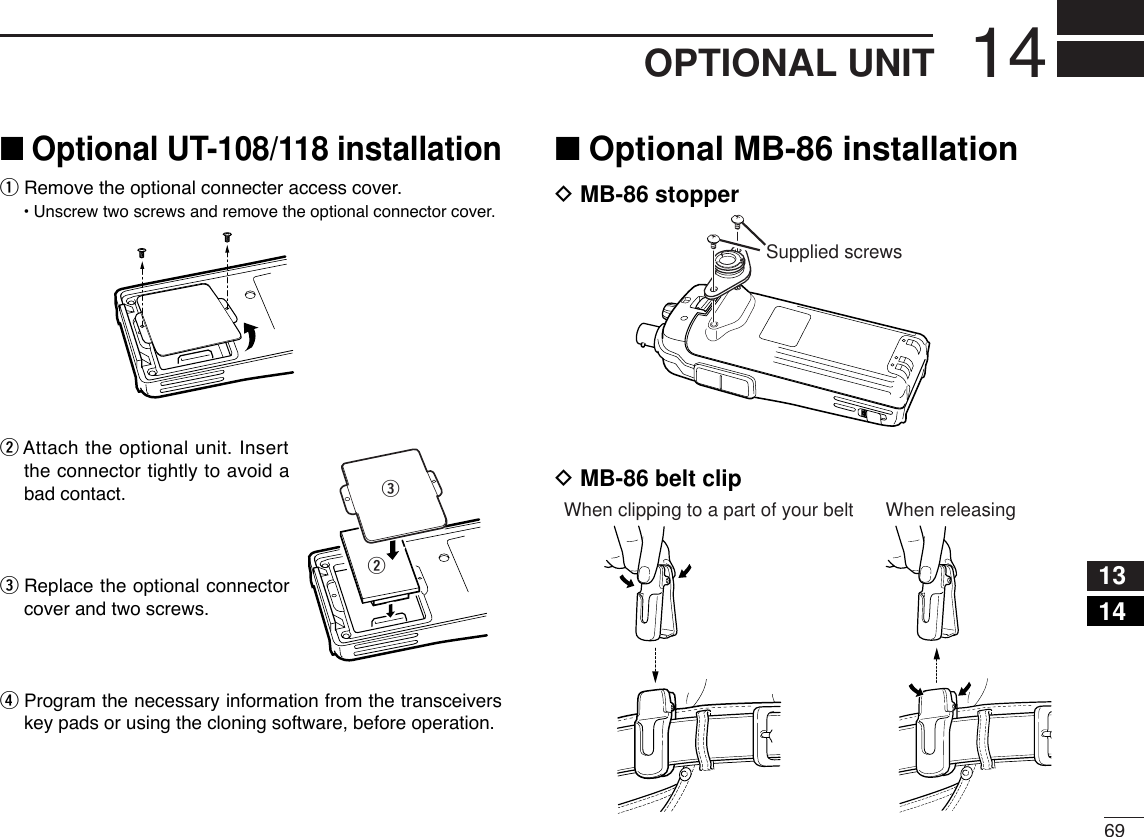
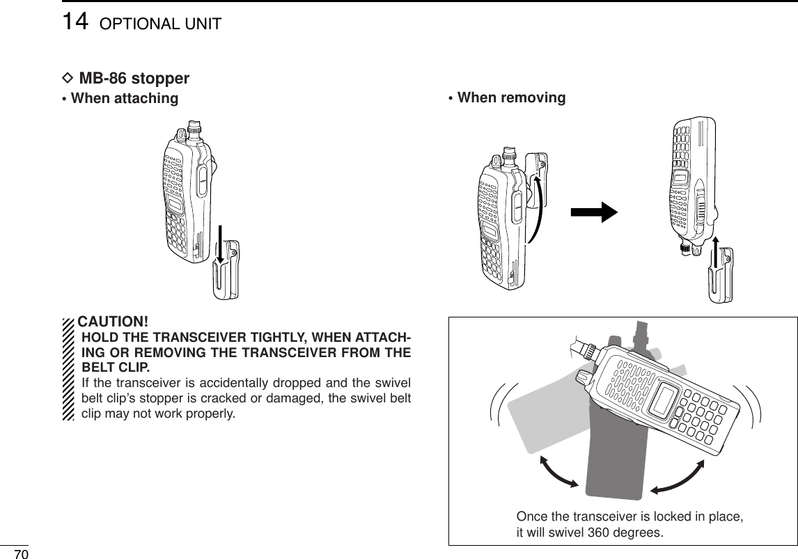
![7115SPECIFICATIONS1415GENERAL•Frequency coverage : (unit: MHz)USA Tx: 144–148/Rx: 136–174*Europe, Taiwan, Korea Tx/Rx: 144–146General (LM), CSA (LM) Tx/Rx: 136–174**Guaranteed: 144–148 MHz range only.•Type of emission : FM•Number of memory channels : 207 (incl. 6 scan edges and 1 call)•Frequency resolution : 5, 10, 12.5, 15, 20, 25, 30, 50 kHz•Operating temperature range : –10°C to +60°C; +14˚F to +140˚F•Frequency stability : ±2.5 ppm (–10°C to +60°C)•Power supply requirement : 7.2 V DC (6–10.3 V DC acceptable;Icom’s battery pack only)•Current drain (at 7.2 V DC: approx.): Transmit at 7 W (High) 2.6 Aat 4 W (Middle) 2.0 Aat 0.5 W (Low) 1.0 AReceive standby 80 mApower save 30 mAmax. audio 250 mA•Antenna connector : BNC (50 Ω)•Dimensions (proj. not included) :54(W) ×139(H) ×36.7(D) mm21⁄8(W)×515⁄32(H)×17⁄16(D) in•Weight (approx.) : 390 g; 13.8 oz (with BP-222N and Ant.)200 g; 7.1 oz (without battery pack and Ant.)TRANSMITTER•Modulation system : Variable reactance frequency mod.•Output power (at 7.2 V) : 7 W/4 W/0.5 W (High/Mid/Low)•Max. frequency deviation : ±5.0 kHz [Wide]/±2.5 kHz [Narrow]•Spurious emissions : Less than –60 dBc•Microphone connector : 3-conductor 2.5 (d) mm (1⁄8″)/2.2 kΩRECEIVER•Receive system : Double-conversion superheterodyne•Intermediate frequencies : 1st: 46.35 MHz, 2nd: 450 kHz•Sensitivity (at 12 dB SINAD) :0.16 µV typical•Squelch sensitivity (threshold) :0.11 µV typical•Selectivity :[Wide] More than 55 dB[Narrow] More than 50 dB•Spurious and image rejection : 80 dB typical•Intermodulation : 65 dB typical•AF output power (at 7.2 V DC):More than 0.3 W at 10% distortion withan 8 Ωload•Ext. speaker connector : 3-conductor 3.5 (d) mm (1⁄8″)/8 Ω•Ext. data connector : 3-conductor 2.5 (d) mm (1⁄8″)All stated specifications are subject to change without notice or obligation.■IC-V82](https://usermanual.wiki/ICOM-orporated/283300/User-Guide-490696-Page-83.png)
![7215 SPECIFICATIONSGENERAL•Frequency coverage : (unit: MHz)USA Tx: 420–450*1/Rx: 400–479*1Europe, Korea Tx/Rx: 430–440General (LM), China Tx/Rx: 400–479*2*1Guaranteed: 440–450 MHz range only.*2Guaranteed: 430–440 MHz range only.•Type of emission : FM•Number of memory channels : 207 (incl. 6 scan edges and 1 call)•Frequency resolution : 5, 10, 12.5, 15, 20, 25, 30, 50 kHz•Operating temperature range : –10°C to +60°C; +14˚F to +140˚F•Frequency stability : ±2.5 ppm (–10°C to +60°C)•Power supply requirement : 7.2 V DC (6–10.3 V DC acceptable;Icom’s battery pack only)•Current drain (at 7.2 V DC: approx.): Transmit at 5 W (High) 2.0 Aat 2 W (Middle) 1.4 Aat 0.5 W (Low) 0.9 AReceive standby 80 mApower save 30 mAmax. audio 250 mA•Antenna connector : BNC (50 Ω)•Dimensions (proj. not included) :54(W) ×139(H) ×36.7(D) mm21⁄8(W)×515⁄32(H)×17⁄16(D) in•Weight (approx.) : 390 g; 13.8 oz (with BP-222N and Ant.)200 g; 7.1 oz (without battery pack and Ant.)TRANSMITTER•Modulation system : Variable reactance frequency mod.•Output power (at 7.2 V) : 5 W/2 W/0.5 W (High/Mid/Low)•Max. frequency deviation : ±5.0 kHz [Wide]/±2.5 kHz [Narrow]•Spurious emissions : Less than –60 dBc•Microphone connector : 3-conductor 2.5 (d) mm (1⁄8″)/2.2 kΩRECEIVER•Receive system : Double-conversion superheterodyne•Intermediate frequencies : 1st: 46.35 MHz, 2nd: 450 kHz•Sensitivity (at 12 dB SINAD) :0.16 µV typical•Squelch sensitivity (threshold) :0.11 µV typical•Selectivity :[Wide] More than 55 dB[Narrow] More than 50 dB•Spurious and image rejection : 70 dB typical•Intermodulation : 65 dB typical•AF output power (at 7.2 V DC):More than 0.3 W at 10% distortion withan 8 Ωload•Ext. speaker connector : 3-conductor 3.5 (d) mm (1⁄8″)/8 Ω•Ext. data connector : 3-conductor 2.5 (d) mm (1⁄8″)All stated specifications are subject to change without notice or obligation.■IC-U82](https://usermanual.wiki/ICOM-orporated/283300/User-Guide-490696-Page-84.png)