ICOM orporated 284400 Scanning Receiver User Manual IC R9500 manual
ICOM Incorporated Scanning Receiver IC R9500 manual
Contents
- 1. Users Manual 1
- 2. Users Manual 2
- 3. Users Manual 3
Users Manual 2
4-19
4
RECEIVE MODES
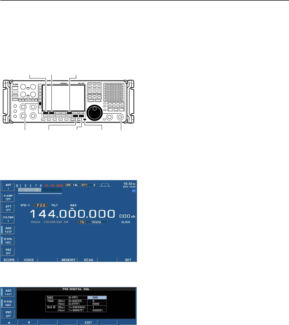
■Digital squelch operation
While in P25 mode operation, 2 types of digital
squelch, NAC or Selective, are available.
qSet the desired frequency and select P25 mode.
wPush [D.SQL] to turn the digital squelch function
ON.
• “NAC” or “SEL”appears when the digital squelch func-
tion is ON.
ePush and hold [D.SQL] for 1 sec. to enter P25 digi-
tal squelch set mode.
rPush [F-1•Y] or [F-2•Z] to select the items, “NAC,”
“TGID” or “Unit ID.”
tPush [F-5•EDIT] to enter digital code programming.
• A cursor appears and blinks.
• Push [F-1•Ω] or [F-2•≈] for cursor movement.
• Push [F-3•DEL] to delete the selected code.
• Using the receiver’s keypad, [0]–[9], can also enter nu-
merals.
• Multifunction switch guide changes to the additional
keys, [A]–[F], for hexadecimal input.
yPush [F-5•SET] to input and set the code.
• The cursor disappears.
uPush [EXIT/SET] to return to the previous indica-
tion.
iWhen the received signal includes a matching code,
squelch opens and the signal can be heard.
• When the received signal’s code does not match, digital
squelch does not open, however, the S-indicator shows
signal strength.
oTo open the digital squelch manually, push [MONI].
• The digital squelch opens temporarily while pushing and
holding [MONI].
!0 To cancel digital squelch, push [D.SQL] several
times to clear the digital squelch.
• “NAC” or “SEL” disappears and “OFF” appears.
• Digital squelch set mode
[EXIT/SET] [MONI][DIGITAL] Main dial[D.SQL]
[F-1•Y] [F-2•Z][F-5•EDIT]

5-1
RECEIVE FUNCTIONS Section 5
■Spectrum scope screen ……………………………………………… 5-2
DCenter mode ………………………………………………………… 5-2
DFix mode ……………………………………………………………… 5-3
DPeak marker function ……………………………………………… 5-4
DWide band-pass filter selection……………………………………… 5-5
DWide band scope function …………………………………………… 5-5
DMini scope screen indication ……………………………………… 5-6
DScope set mode ……………………………………………………… 5-6
■Preamplifier ……………………………………………………………… 5-9
■Attenuator ……………………………………………………………… 5-9
■AGC function …………………………………………………………… 5-10
DSelecting the preset value …………………………………………5-10
DAdjusting the AGC time constant …………………………………5-10
DSetting the AGC time constant preset value ……………………5-10
■Twin PBT operation …………………………………………………… 5-11
■IF filter selection ……………………………………………………… 5-12
DIF filter selection …………………………………………………… 5-12
DFilter passband width setting ……………………………………… 5-12
DRoofing filter selection ……………………………………………… 5-13
DDSP filter shape …………………………………………………… 5-13
DFilter shape set mode ……………………………………………… 5-13
■Noise blanker ………………………………………………………… 5-15
DNB set mode ………………………………………………………… 5-15
■Noise reduction ………………………………………………………… 5-16
■Notch function ………………………………………………………… 5-16
■Autotune function ……………………………………………………… 5-17
■AFC function …………………………………………………………… 5-17
5-2
■Spectrum scope screen
This DSP-based spectrum scope allows you to display
the conditions on the selected band, as well as relative
strengths of signals. The IC-R9500 has two modes for
the spectrum indication— one is center mode, and an-
ther one is fixed mode.
In addition, the IC-R9500 has a mini-scope screen to
save screen space.
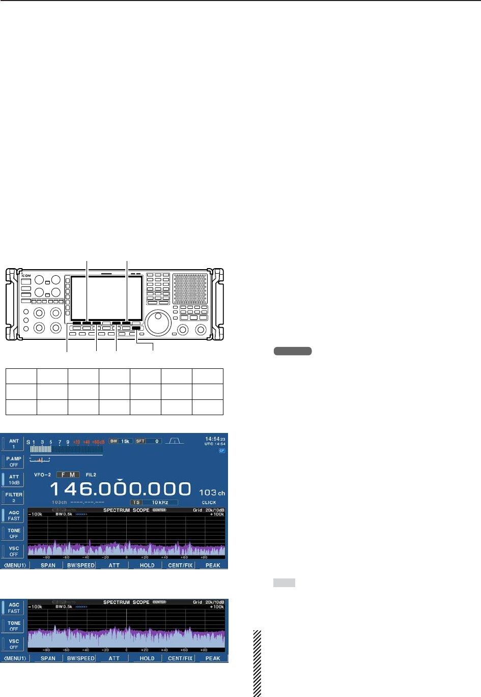
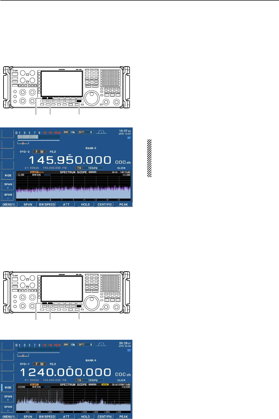
DCenter mode
Displays signals around the set frequency within the
selected span. The set frequency is always displayed
at the center of the screen.
qPush [EXIT/SET] several times to close a multi-
function screen, if necessary.
wPush [F-1•SCOPE] to select the scope screen.
• The spectrum scope shows the peak level holding func-
tion. Peak levels are displayed in the background of the
current spectrum in a different color until the receive fre-
quency changes. This can be deactivated and the wave-
form color can be set in scope set mode. (p. 5-7)
ePush [F-6•CENT/FIX] to select the center mode.
• “ ” is displayed when center mode is selected.
rPush [F-2•SPAN] once.
• Multifunction switch guide changes to the span setting
guide.
tPush [SPAN+] or [SPAN–] several times to select
the scope span.
• ±2.5 k, ±5.0 k, ±10 k, ±25 k, ±50 k, ±100 k, ±250 k,
±500 k, ±1 M, ±2.5 M and ±5 MHz are available.
yPush [F-3•BW/SPEED] once.
• Multifunction switch guide changes to the resolution
band width/speed setting guide.
uPush [BW+] or [BW–] several times to select the
resolution band width.
• 0.2 k, 0.5 k, 1 k, 2 k, 5 k, 10 k and 20 kHz are available.
iPush [SPEED–] or [SPEED+] several times to se-
lect the sweep speed.
oPush [F-4•ATT] several times to activate an attenu-
ator or turn the attenuator OFF.
• 10, 20 and 30 dB attenuators are available.
!0 Push [F-5•HOLD] to freeze the current spectrum
waveform.
• “ ” appears while the function is in use.
• The peak hold function can be deactivated in scope set
mode.
!1 Push [EXIT/SET] to exit the scope screen.
NOTE: If a strong signal is received, a ghost wave-
form may appear. Push [F-4•ATT] several times to
activate the spectrum scope attenuator in this case.
Spurious signal waveforms may be displayed if gen-
erated in the internal scope circuit and do not indi-
cate a receiver malfunction.
HOLD
CENTER
[EXIT/SET][F-5][F-3]
[F-2]
[F-1]
[F-6]
[F-5][F-3][F-2][F-1] [F-6][F-4] [F-7]
SPAN
BW/SPEED
CENT/FIX
PEAK
SET
MENU1
ATT HOLD
W-BPFMENU2
5RECEIVE FUNCTIONS
• Observed indication example
5-3
5
RECEIVE FUNCTIONS
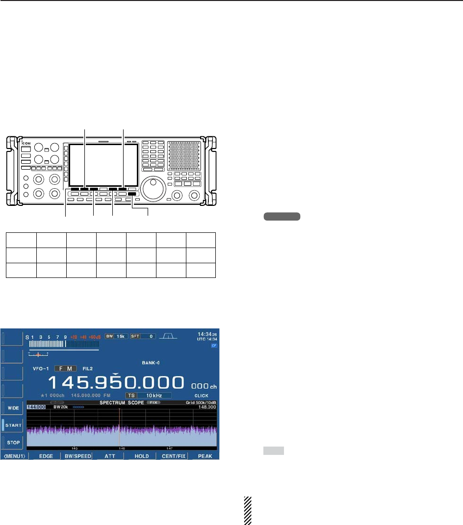
DFixed frequency mode
Displays signals within the specified frequency range.
The selected frequency band conditions can be ob-
served at a glance when using this mode.
qPush [EXIT/SET] several times to close a multi-
function screen, if necessary.
wPush [F-1•SCOPE] to select the scope screen.
• The spectrum scope shows the peak level holding func-
tion. Peak levels are displayed in the background of the
current spectrum in a different color until the receive fre-
quency changes. This can be deactivated and the
waveform color can be set in scope set mode. (p. 5-7)
ePush [F-6•CENT/FIX] to select the fixed mode.
• “ ” is displayed when fix mode is selected.
rPush [F-2•EDGE] once.
• Multifunction switch guide changes to the resolution
band width/speed setting guide.
tPush [START] then edit the desired frequency using
the keypad to set the lower frequency edge, and
push [STOP] then edit the desired frequency using
the keypad to set the higher frequency edge.
yPush [F-3•BW/SPEED] once.
• Multifunction switch guide changes to the resolution
band width/speed setting guide.
uPush [BW+] or [BW–] several times to select the
resolution band width.
• 0.2 k, 0.5 k, 1 k, 2 k, 5 k, 10 k and 20 kHz are available
depends on the frequency range.
iPush [SPEED–] or [SPEED+] several times to se-
lect the sweeping speed.
oPush [F-4•ATT] several times to activate an attenu-
ator or turn the attenuator OFF.
• 10, 20 and 30 dB attenuators are available.
!0 Push [F-5•HOLD] to freeze the current spectrum
waveform.
• “ ” appears while the function is in use.
• The peak hold function can be deactivated in scope set
mode.
!1 Push [EXIT/SET] to exit the scope screen.
NOTE: If a strong signal is received, a ghost wave-
form may appear. Push [F-4•ATT] several times to
activate the spectrum scope attenuator in this case.
HOLD
FIX
[F-5][F-3][F-2][F-1] [F-6][F-4] [F-7]
EDGE
BW/SPEED
CENT/FIX
PEAK
SET
MENU1
ATT HOLD
W-BPFMENU2
[EXIT/SET][F-5][F-3]
[F-2]
[F-1]
[F-6]
5-4
5RECEIVE FUNCTIONS
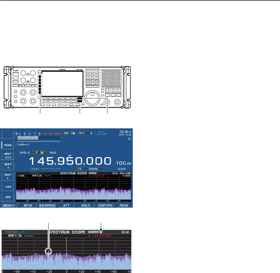
DPeak marker function
The peak marker function can display the frequencies
of several peaks in order.
qPush [EXIT/SET] several times to close a multi-
function screen, if necessary.
wPush [F-1•SCOPE] to select the scope screen.
• The spectrum scope shows the peak level holding func-
tion. Peak levels are displayed in the background of the
current spectrum in a different color until the receive fre-
quency changes. This can be deactivated and the
waveform color can be set in scope set mode. (p. 5-7)
ePush [F-6•CENT/FIX] to select center or fixed
mode.
rPush [F-7•PEAK] once.
• Multifunction switch guide changes to the peak selec-
tion guide.
tPush [PEAK] to place the marker on the first peak.
• Push [NEXT level] to search for the next peak level.
• Push [NEXTΩ] to search for the next peak level of lower
frequency.
• Push [NEXT≈] to search for the next peak level of
higher frequency.
• Push and hold [➔RX] to overwrite the peak level fre-
quency as the new center frequency.
• Push [OFF] to turn OFF the maker.
• “<<” or “>>” appears when the marker is out of range.
yPush [EXIT/SET] to return to the previous screen.
Peak frequencyPeak indicator
[EXIT/SET]
Multi-function switch [F-7•PEAK]
5-5
5
RECEIVE FUNCTIONS
DWide band-pass filter selection
The wide band-pass filter function can change the RF
band pass filter and the select the wide band-pass filter
qDuring spectrum scope display ON, push
[F-1•MENU1] to select the second scope menu.
wPush [F-2•W-BPF] once or twice to select the wide
band-pass filter setting ON, AUTO or OFF.
• “W-BPF” appears when ON is selected, “W-BPF AUTO”
appears when AUTO is selected or no indication ap-
pears when OFF is selected.
• While W-BPF AUTO is activate, the wide band pass filter
is automatically selected when wider than 500 kHz span
is selected.
ePush [EXIT/SET] to return to the previous screen.
NOTE: The RF filter circuit is commonly used for the
scope signal and received signal. When W-BPF is
selected, or W-BPF AUTO is selected with wider than
500 kHz span, interference may heard due to the
received signal passing through the high pass filter
instead of the specified band-pass filters.
[EXIT/SET][F-2]
[F-1]
DWide band scope function
The wide band scope function is available to sweep a
wide frequency range (max. ±500 MHz). While this
function is active, AF monitor is not available.
qDuring spectrum scope display ON, push
[F-2•SPAN] to select the span setting condition.
• Multifunction switch guide changes to the span selec-
tion guide.
wPush [WIDE] to select the wide band scope function
ON or OFF.
• When ON is selected, audio disappears.
ePush [SPAN+] or [SPAN–] several times to select
the scope span.
• ±5.0 M, ±10 M, ±25 M, ±50 M, ±100 M, ±250 M and
±500 M are available.
rPush [EXIT/SET] to return to the previous screen.
[EXIT/SET][F-2]
[F-1]
5-6
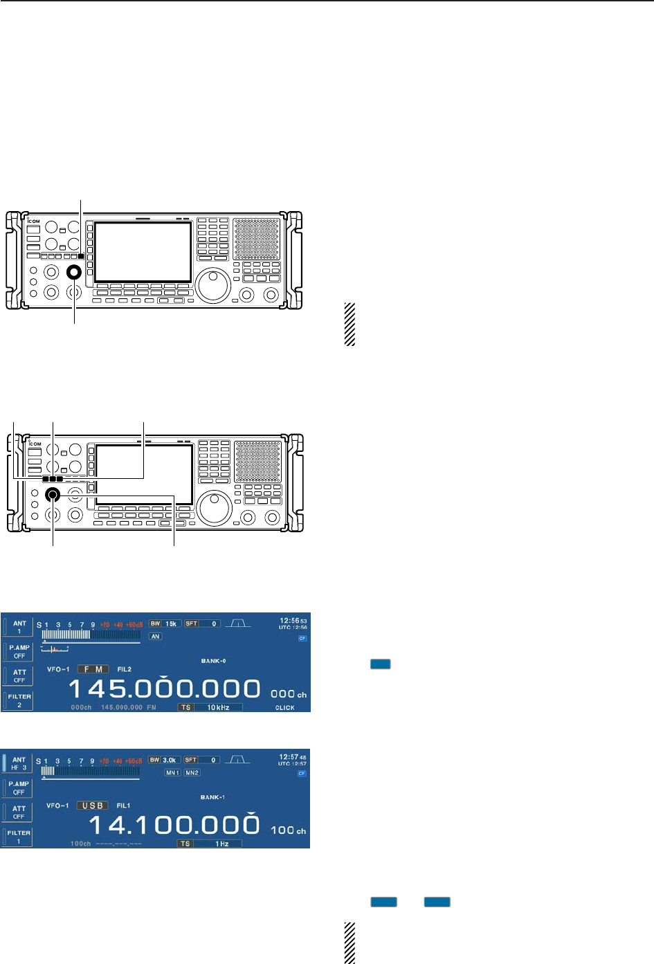
DMini scope screen indication
The mini scope screen can be displayed with another
screen display, such as set mode menu, decoder
screen, memory list screen, etc. simultaneously.
qSet the scope mode (center or fixed), marker, at-
tenuator, span, etc. in advance. (pgs. 5-2, 5-3)
wPush [M.SCOPE] to toggle the mini scope indica-
tion ON and OFF.
[M.SCOPE]
5FUNCTIONS FOR RECEIVE
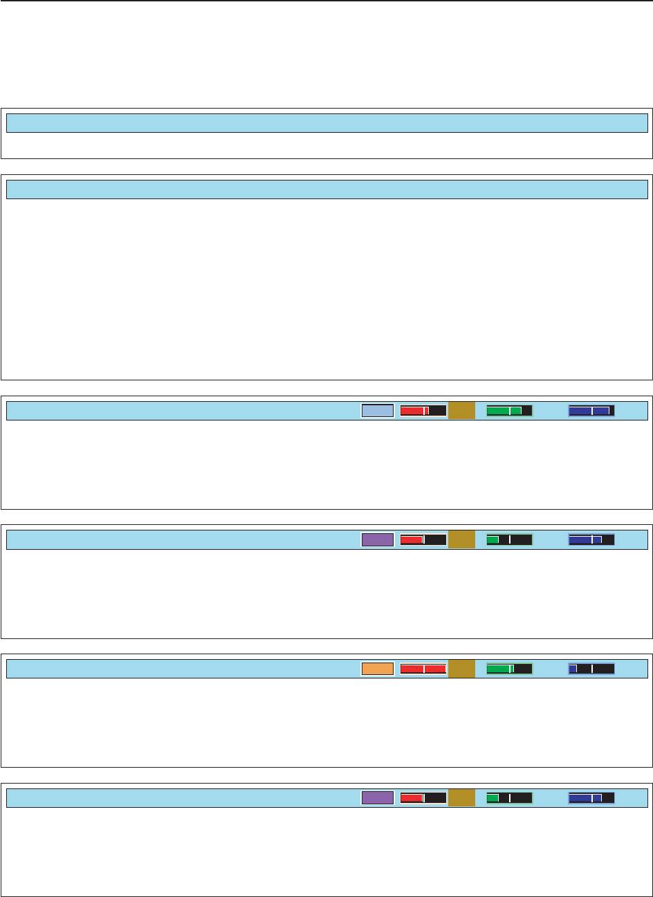
DScope set mode
This set mode is used to set the waveform color, cen-
ter frequency indication for center mode, etc.
qDuring spectrum scope display ON, push
[F-1•MENU1] to select the second scope menu.
wPush [F-7•SET] to enter scope set mode screen.
• Push [F-7•WIDE] to toggle the screen size between nor-
mal and wide.
ePush [F-1•Y] or [F-2•Z] to select the desired set
item.
rSet the desired condition using the main dial.
• Push and hold [F-4•DEF] for 1 sec. to select the default
condition or value.
• Push [F-3•Ω≈] to select the set contents for some
items.
tPush [EXIT/SET] to exit from set mode.
[EXIT/SET] Main dial
[F-1•Y] [F-2•Z][F-3•Ω ≈]
[F-4•DEF]
[F-7•WIDE]
5-7
DScope set mode (continued)
5
RECEIVE FUNCTIONS
Turn the peak level holding function ON or OFF.
Max Hold
ON
Select the center frequency of the spectrum scope
indication (center mode only). • Filter center : Shows the selected filter’s center
frequency at the center.
• Carrier Point Center
: Shows the selected operating
mode carrier point frequency at
the center.
• Carrier Point Center (Abs. Freq.)
: In addition to the carrier point
center setting above, the actual
frequency is displayed at the bot-
tom of the scope.
Center Type Display
Filter Center
Set the waveform color for the currently received sig-
nals. • The color is set in RGB format.
• Push [F-3•Ω≈] to select R (Red), G (Green) and B
(Blue), and rotate the ratio from 0 to 255 range.
• The set color is indicated in the box beside the RGB
scale.
Waveform Color (Current)
161 185 221
Set the waveform color for the receiving signals max-
imum level. • The color is set in RGB format.
• Push [F-3•Ω≈] to select R (Red), G (Green) and B
(Blue), and rotate the ratio from 0 to 255 range.
• The set color is indicated in the box beside the RGB
scale.
Waveform Color (Max Hold)
130 66 176
Set the marker color for the displayed frequency while
the fix mode. • The color is set in RGB format.
• Push [F-3•Ω≈] to select R (Red), G (Green) and B
(Blue), and rotate the ratio from 0 to 255 range.
• The set color is indicated in the box beside the RGB
scale.
Marker Color (RX)
255 150 50
Set the marker color for the peak frequency of the re-
ceiving signals. • The color is set in RGB format.
• Push [F-3•Ω≈] to select R (Red), G (Green) and B
(Blue), and rotate the ratio from 0 to 255 range.
• The set color is indicated in the box beside the RGB
scale.
Waveform Color (Max Hold)
130 66 176

5-8
5RECEIVE FUNCTIONS
Set the next peak excursion level from 0 to 80 dB in
1 dB steps. (default: 6 dB)
If the difference between the signal peak and adja-
cent minimum values is less than the set level, it will
not be found as the next peak level when [NEXTΩ] or
[NEXT≈] is pushed.
Peak Excursion
6dB
Set the next peak threshold level from 0 to –100 dB
in 1 dB steps. (default: –90dB)
If the difference between the signal and last peak sig-
nal values is more than the set level, it will not be
found as the next peak level when [NEXTΩ] or
[NEXT≈] is pushed.
Peak Threshold
–90dB
DScope set mode (continued)
5-9
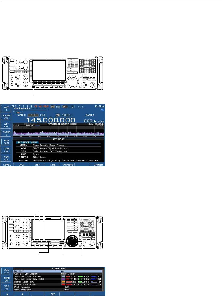
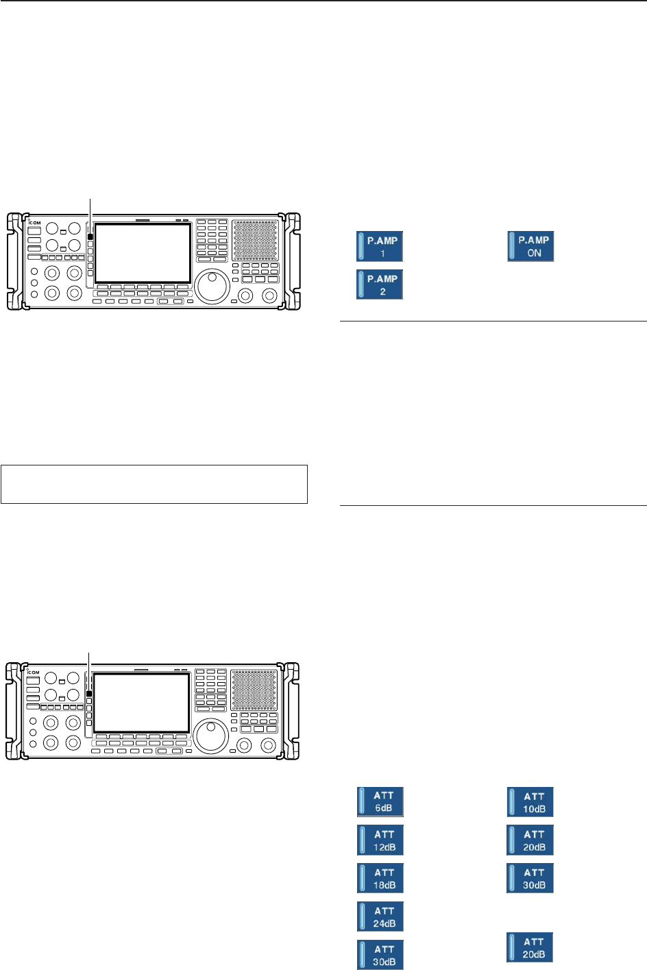
■Preamplifier
The preamp amplifies received signals in the receiver
front end, to improve the S/N ratio and sensitivity. Set
this to preamp 1 or preamp 2 when receiving weak sig-
nals.
➥Push [P.AMP] several times to set the preamp OFF,
preamp 1 ON or preamp 2 ON.
✔
About the “P.AMP2”
The “P.AMP 2” is a high gain receive amplifier. When
the “P.AMP 2” is used when strong signal are present,
distortion sometimes results. If this occurs, use the re-
ceiver with the “P.AMP 1” or “P.AMP OFF” setting.
The “P.AMP 2” is most effective when:
• Used on bands above 24 MHz and when signals are
weak.
• Receive sensitivity is insufficient during low gain, or
while using a narrow band antenna (such as small
loop, a Beverage antenna or a short Yagi antenna).
■Attenuator
The attenuator prevents a desired signal from being
distorted by a very strong signals are near the desired
frequency or when very strong electric fields, such as
from broadcasting stations, are near your location.
➥Push [ATT] several times to select the desired at-
tenuator or attenuator OFF.
• During HF bands operation, 6, 12, 18, 24, 30 dB are
available.
• During 30–1150 MHz operation, 10, 20, 30 dB are available.
• During 1150–3335 MHz operation, only 20 dB is avail-
able.
➥Push and hold [ATT] for 1 sec. to turn OFF the at-
tenuator, when it’s ON.
[ATT]
[P.AMP]
5
RECEIVE FUNCTIONS
• HF bands6dB
attenuation
12 dB
attenuation
18 dB
attenuation
24 dB
attenuation
30 dB
attenuation
• 30–1150 MHz
10 dB
attenuation
20 dB
attenuation
30 dB
attenuation
• 1150–3335 MHz
20 dB
attenuation
During 1150–3335 MHz (ANT2) operation, either the
preamplifier or attenuator is activate exclusively.
• Below 30 MHz
For all
HF bands
High-gain pre-
amp for 24 MHz
band and above
• Above 30 MHz
Only ON/OFF
is available
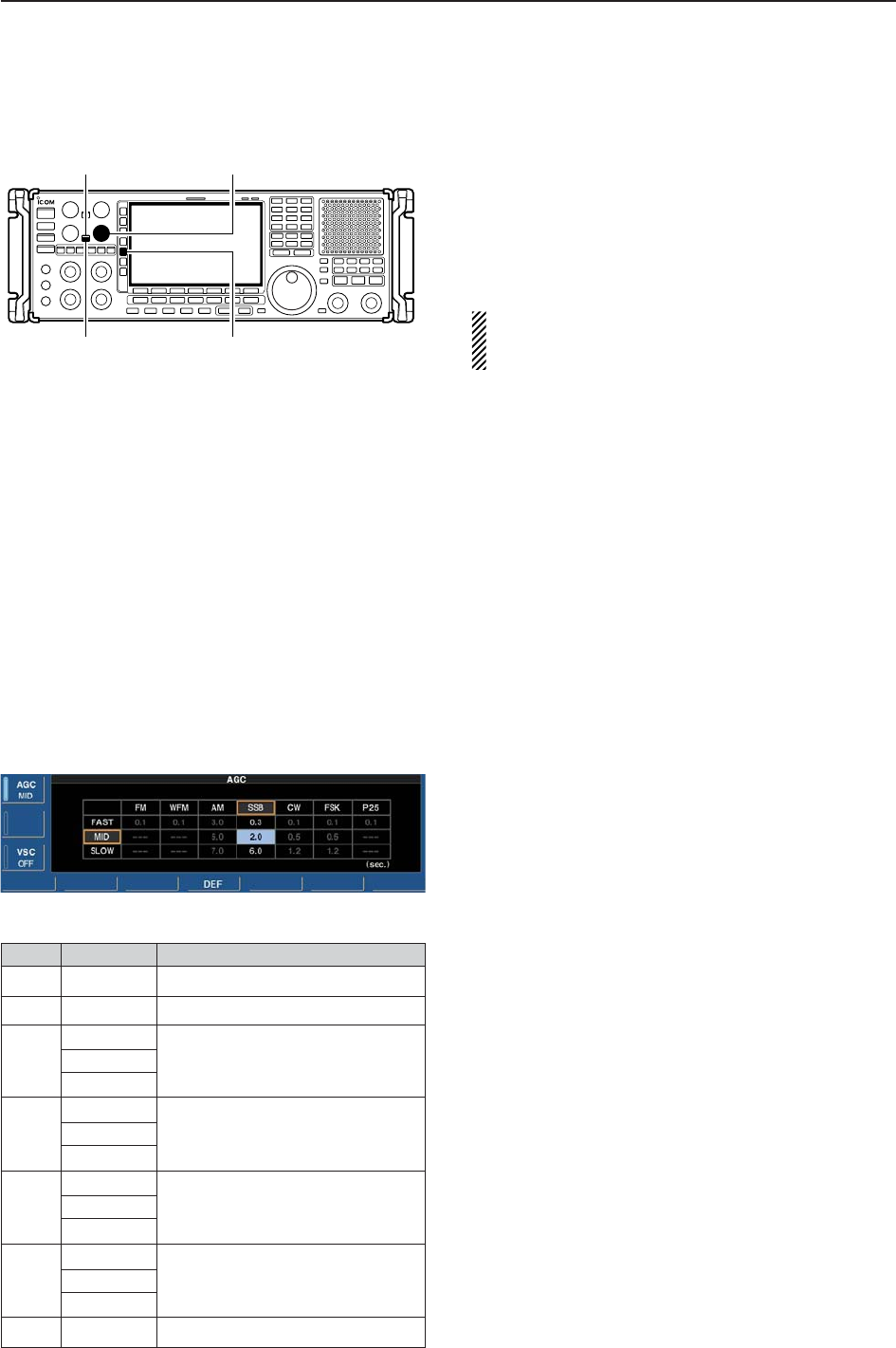
■AGC function
The AGC (auto gain control) controls receiver gain to
produce a constant audio output level even when the
received signal strength varies greatly.
The receiver has 3 preset AGC characteristics (time
constant: fast, mid, slow) for non-FM/WFM or P25
mode.
The FM/WFM or P25 mode AGC time constant is
fixed as ‘FAST’ (0.1 sec.) and AGC time constant
cannot be selected.
DSelecting the preset value qSelect non-FM/WFM or P25 mode.
wPush [AGC] several times to select AGC fast, AGC
medium (MID) or AGC slow.
• Push and hold [AGC VR/OFF] for 1 sec. to turn the AGC
function OFF.
DAdjusting the AGC time constant qSelect non-FM/WFM or P25 mode.
wPush [AGC VR/OFF] once or twice to select AGC
volume (VR), then rotate [AGC] control to adjust the
AGC time constant.
• [AGC VR] indicator lights green and “VR” appears in-
stead of “FAST,” “MID” or “SLOW.”
DSetting the AGC time constant preset value
qSelect the desired mode (not FM/WFM or P25
mode).
wPush and hold [AGC] for 1 sec. to enter AGC set
mode.
ePush [AGC] several times to select FAST time con-
stant.
rRotate the main dial to set the desired time constant
for ‘AGC FAST.’
• AGC time constant can be set between 0.1 to 8.0 sec.
(depends on mode) or turned OFF.
• Push and hold [F-4•DEF] for 1 sec. to select a default
value.
tPush [AGC] to select medium time constant.
yRotate the main dial to set the desired time constant
for ‘AGC MID.’
• AGC time constant can be set between 0.1 to 8.0 sec.
(depends on mode) or turned OFF.
• Push and hold [F-4•DEF] for 1 sec. to select a default value.
uPush [AGC] to select slow time constant.
iRotate the main dial to set the desired time constant
for ‘AGC SLOW.’
• AGC time constant can be set between 0.1 to 8.0 sec.
(depends on mode) or turned OFF.
• Push and hold [F-4•DEF] for 1 sec. to select a default value.
oSelect another mode (not FM/WFM or P25). Repeat
steps eto iif desired.
!0 Push [EXIT/SET] to exit the AGC set mode screen.
[AGC]
[AGC] control[AGC VR] indicator
[AGC VR/OFF]
5-10
5RECEIVE FUNCTIONS
Mode Default Selectable AGC time constant
FM 0.1 (FAST) Fixed
WFM 0.1 (FAST) Fixed
3.0 (FAST) 0.3, 0.5, 0.8, 1.2, 1.6, 2.0, 2.5, 3.0,
AM 5.0 (MID) 4.0, 5.0, 6.0, 7.0, 8.0
7.0 (SLOW)
0.3 (FAST) 0.1, 0.2, 0.3, 0.5, 0.8, 1.2, 1.6, 2.0,
SSB 2.0 (MID) 2.5, 3.0, 4.0, 5.0, 6.0
6.0 (SLOW)
0.1 (FAST) 0.1, 0.2, 0.3, 0.5, 0.8, 1.2, 1.6, 2.0,
CW 0.5 (MID) 2.5, 3.0, 4.0, 5.0, 6.0
1.2 (SLOW)
0.1 (FAST) 0.1, 0.2, 0.3, 0.5, 0.8, 1.2, 1.6, 2.0,
FSK 0.5 (MID) 2.5, 3.0, 4.0, 5.0, 6.0
1.2 (SLOW)
P25 0.1 (FAST) Fixed
• Selectable AGC time constant (unit: sec.)
5-11
5
RECEIVE FUNCTIONS
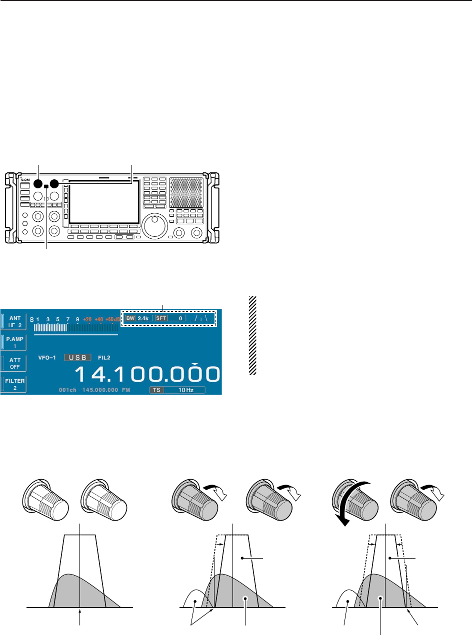
■Twin PBT operation
PBT (Passband Tuning) electronically narrows the IF
passband width by shifting the IF frequency slightly
outside of the IF filter passband, rejecting interference.
The IC-R9500 uses DSP for the PBT function. Moving
both [TWIN PBT] controls to the same position shifts
the IF.
➥The LCD shows the passband width and shift fre-
quency graphically.
➥Push and hold [FILTER] for 1 sec. to enter the filter
set screen. Current passband width and shift fre-
quency is displayed in the filter set screen.
➥To set the [TWIN PBT] controls to the center posi-
tions, push and hold [PBT CLR] for 1 sec.
The variable range depends on the passband width
and mode. The edge of the variable range is half of the
passband width, and PBT is adjustable in 25 or 50 Hz
steps.
• [TWIN PBT] should normally be set to the center posi-
tions (PBT setting is cleared) when there is no interfer-
ence.
• When PBT is used, the audio tone may be changed.
• Not available for FM/WFM or P25 mode.
• While rotating [TWIN PBT], noise may occur. This comes
from the DSP unit and does not indicate an equipment
malfunction.
• PBT operation example
(PBT1) (PBT2) (PBT1) (PBT2) (PBT1) (PBT2)
IF center frequency Interference Desired signal
Passband
Both controls at
center position Reducing a lower
passband Reducing both higher and
lower passbands
Interference Interference
Desired signal
Passband
or
Shows filter width, shifting value and condition
[TWIN PBT] for lower
[PBT CLEAR]
[TWIN PBT] for higher

■IF filter selection
The receiver has 3 passband width IF filters for each
mode.
For FM mode, the passband width is fixed and 3 pass-
band widths are available.
For WFM and P25 mode, the passband width is fixed.
For AM mode, the passband width can be set within
200 Hz to 10 kHz in 200 Hz steps. A total of 50 pass-
band widths are available.
For SSB and CW modes, the passband width can be
set within 50 to 3600 Hz in 50 or 100 Hz steps. A total
of 41 passband widths are available.
For FSK mode, the passband width can be set within
50 to 2700 Hz in 50 or 100 Hz steps. A total of 32 pass-
band widths are available.
The filter selection is automatically memorized in
each mode.
The PBT shift frequencies are automatically memo-
rized for each filter.
DIF filter selection qSelect the desired mode.
wPush [FILTER] several times to select the IF filter 1,
2 or 3.
• The selected passband width and filter number is dis-
played in the LCD.
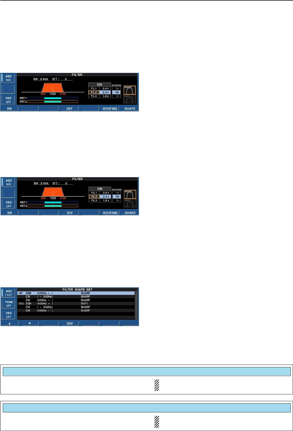
DFilter passband width setting (except FM/WFM or P25 mode)
qPush and hold [FILTER] for 1 sec. to enter filter set
screen.
wSelect any mode except FM/WFM or P25 mode.
• Passband widths for FM modes are fixed and cannot be set.
ePush [FILTER] several times to select the desired IF
filter.
rWhile pushing [F-1•BW], rotate the main dial to set
the desired passband width.
• In AM mode, the passband width can be set within the
following range.
200 Hz to 10 kHz 200 Hz steps
• In SSB and CW modes, the passband width can be set
within the following range.
50 to 500 Hz 50 Hz steps
600 to 3600 Hz 100 Hz steps
• In FSK mode, the passband width can be set within the
following range.
50 to 500 Hz 50 Hz steps
600 to 2700 Hz 100 Hz steps
• Push and hold [F-4•DEF] for 1 sec. to select the default value.
tRepeat steps wto rif desired.
yPush [EXIT/SET] to exit filter set screen.
The PBT shift frequencies are cleared when the
passband width is changed.
This filter set screen graphically displays the PBT
shift frequencies and operations.
[FIL]
5-12
5RECEIVE FUNCTIONS
5-13
5
RECEIVE FUNCTIONS
DRoofing filter selection The IC-R9500 has 3, 6 15 and 50 kHz roofing filters at
the 1st IF frequency. The roofing filter provides inter-
ference reduction from nearby strong signals.
qPush and hold [FILTER] for 1 sec. to enter filter set
screen.
wSelect any mode except FM/WFM or P25 mode.
ePush [F-6•ROOFING] to select the desired filter
width from 50 kHz, 15 kHz (default), 6 kHz and
3kHz.
• Push and hold [F-4•DEF] for 1 sec. to select a default
value.
rPush [EXIT•SET] to exit filter set screen.
DDSP filter shape The type of DSP filter shape for each SSB, SSB data
and CW can be selected independently from soft and
sharp.
qPush and hold [FILTER] for 1 sec. to enter filter set
screen.
wSelect SSB, SSB data or CW mode.
ePush [F-7•SHAPE] to select the desired filter shape
from soft and sharp.
rPush [EXIT•SET] to exit filter set screen.
The filter shape can be set for each band (HF and
50 MHz bands), mode, and passband width (CW only)
independently as your default setting in filter shape set
mode.
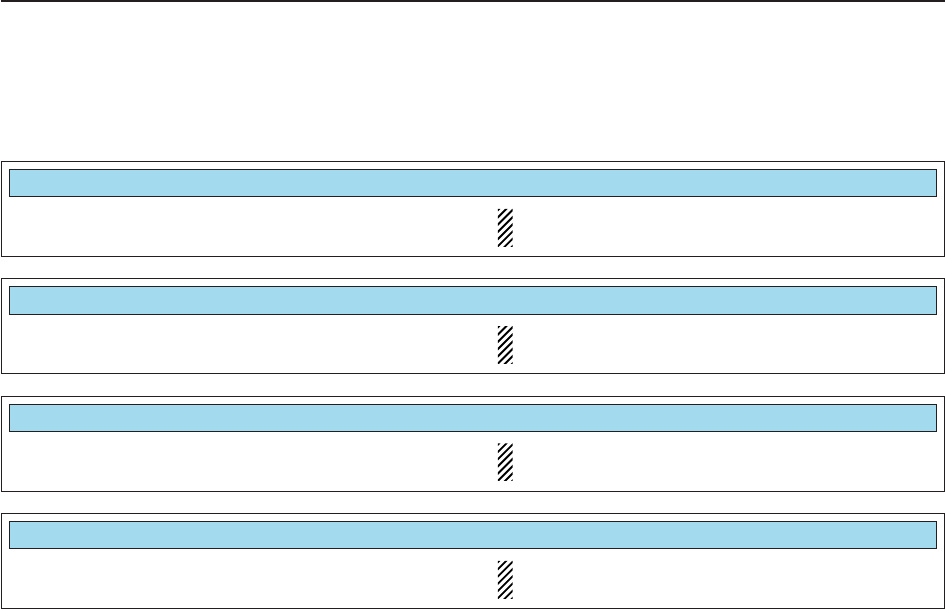
DFilter shape set mode The type of DSP filter shape for each SSB and CW
can be selected independently from soft and sharp.
qPush and hold [FILTER] for 1 sec. to enter filter set
screen.
wPush and hold [F-7•SHAPE] for 1 sec. to enter filter
shape set mode.
ePush [F-1•Y] or [F-2•Z] to select the desired item.
rRotate the main dial to select the filter shape from
soft and sharp.
tPush [EXIT/SET] to exit filter shape set mode.
Select the filter shape for SSB mode in HF bands. The set filter shape is automatically used only
when the IF filter is set to 600 Hz or wider.
HF SSB (600Hz – )
SOFT
Select the filter shape for CW mode in HF bands. The set filter shape is automatically used only
when the IF filter is set to 500 Hz or narrower.
CW ( – 500Hz)
SHARP
DFilter shape set mode (continued)
5-14
5RECEIVE FUNCTIONS
Select the filter shape for CW mode in HF bands. The set filter shape is automatically used only
when the IF filter is set to 600 Hz or wider.
CW (600Hz – )
SHARP
Select the filter shape for SSB mode in VHF/UHF
bands. The set filter shape is automatically used only
when the IF filter is set to 600 Hz or wider.
V/U SSB (600Hz – )
SOFT
Select the filter shape for CW mode in VHF/UHF
bands. The set filter shape is automatically used only
when the IF filter is set to 500 Hz or narrower.
CW ( – 500Hz)
SHARP
Select the filter shape for CW mode in VHF/UHF
bands. The set filter shape is automatically used only
when the IF filter is set to 600 Hz or wider.
CW (600Hz – )
SHARP
5-15
5
RECEIVE FUNCTIONS
■Noise blanker
The noise blanker eliminates pulse-type noise such as
the noise from car ignitions. The noise blanker is not
available for FM/WFM or P25 mode.
qPush [NB] several times to select the noise blanker
function, NB1 or NB2, and OFF.
• [NB] indicator above this switch lights green.
• “NB1” or “NB2” appears on the display when either is
ON.
wRotate [NB] control to adjust the noise blanker
threshold level.
When using the noise blanker, received signals may
be distorted if they are excessively strong or the
noise type is other than pulsing. Turn the noise
blanker OFF, or rotate [NB] control to a shallow po-
sition in this case.
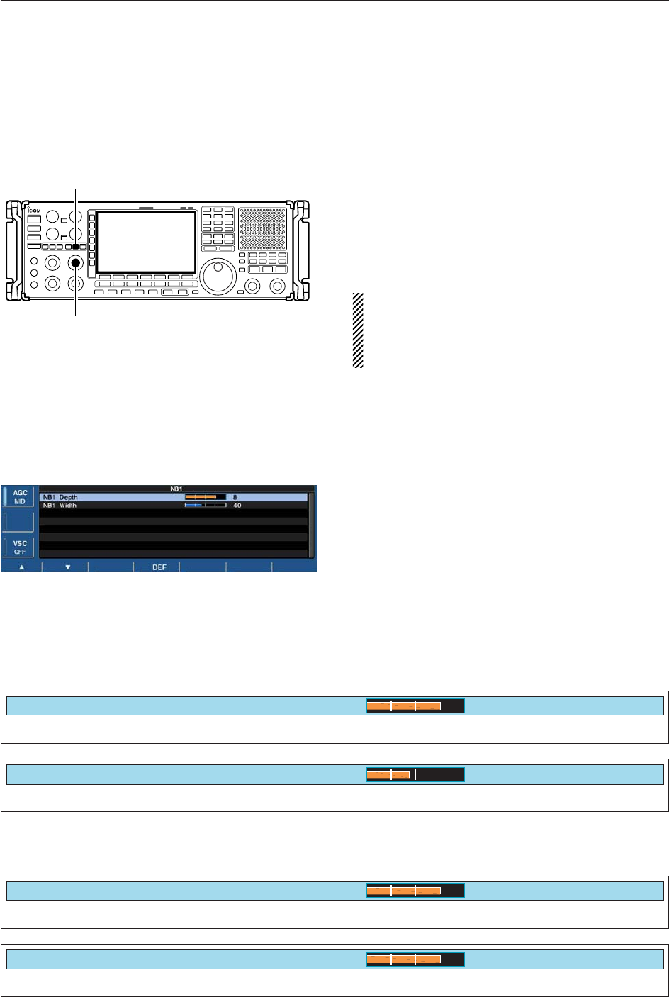
DNB set mode To deal with various type of noises, attenuation level
and noise width can be set in NB set mode. Two of
noise blanker, NB1 and NB2, can be set indepen-
dently.
qTurn ON the desired noise blanker, NB1 or NB2.
• When entering NB1 set mode, this step can be skipped.
wPush and hold [NB] for 1 sec. to enter NB1 (or NB2)
set mode.
ePush [F-1•Y] or [F-2•Z] to select the desired item.
rRotate the main dial to set the desired level or value.
• Push and hold [F-4•DEF] for 1 sec. to select a default
value.
tPush [EXIT/SET] to exit NB1 (or NB2) set mode.
[NB]
[NB] control
Set the noise attenuation level from 1 to 10.
NB1 Depth
8
Set the noise pulse width from 1 to 100.
NB1 Width
40%
• NB1 set mode
Set the noise attenuation level from 1 to 10.
NB2 Depth
8
Set the noise pulse width from 1 to 100.
NB2 Width
80%
• NB2 set mode
5-16
5RECEIVE FUNCTIONS
■Noise reduction
The noise reduction function reduces random noise
components and enhances desired signals which are
buried in noise. The DSP performs the random noise
reduction function.
qPush the [NR] to turn the noise reduction ON.
• [NR] indicator above this switch lights green.
wRotate the [NR] control to adjust the noise reduction
level.
ePush the [NR] switch to turn the noise reduction
OFF.
• [NR] indicator lights off.
Setting the [NR] control too high can result in audio
signal masking or distortion. Set the [NR] control for
maximum readability.
■Notch function
This receiver has auto and manual notch functions.
The auto notch function uses DSP to automatically at-
tenuates up to 3 beat tones, tuning signals, etc., even if
they are moving. The manual notch can be set to at-
tenuate a frequency via the [NOTCH1]/[NOTCH2] con-
trols.
The auto notch can be used in SSB, AM, FM and WFM
modes.
The manual notch can be used in SSB, CW, FSK and
AM modes.
• Auto notch indication
➥Push [ANF] to turn the auto notch function ON and
OFF in FM, WFM, AM and SSB modes.
• [ANF] indicator above this switch lights green.
• “ ” appears when auto notch is in use.
• Manual notch indication
➥Push [NOTCH1] or [NOTCH2] to turn the manual
notch function ON and OFF, manual and OFF in
AM, SSB, CW and FSK modes.
• [NOTCH1]/[NOTCH2] indicators above these switches
light green.
• Push and hold [NOTCH1] or [NOTCH2] for 1 sec. to se-
lect the notch filter width for manual notch from wide,
middle and narrow.
• Set to attenuate a frequency for manual notch via the
[NOTCH1] or [NOTCH2] controls.
• “ ” or “ ” appear when manual notch is in use.
While tuning the manual notch, noise may be heard.
This comes from the DSP unit and does not indicate
an equipment malfunction.
MN2
MN1
AN
[ANF]
[NOTCH1] control [NOTCH2] control
[NOTCH1] [NOTCH2]
[NR]
[NR] control
5-17
5
RECEIVE FUNCTIONS
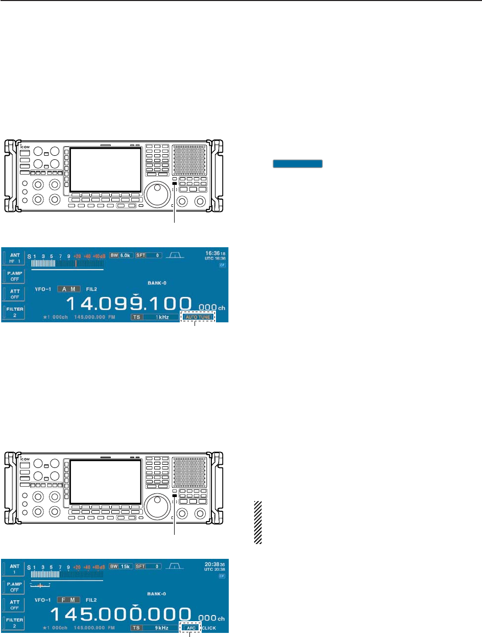
■Autotune function
The Automatic tuning function tunes the displayed fre-
quency (max. ±5 kHz) automatically when an off fre-
quency signal is received. This function is active while
in AM, SSB or CW is selected.
➥Push [AUTOTUNE] (AFC) to toggle the autotune
function ON or OFF.
• “ ” blinks when autotune function is acti-
vate.
• After 30 sec. has passed, the autotune function stops
tuning automatically even it’s still off frequency.
Appears
AUTO TUNE
[AFC•AUTOTUNE]
■AFC function
The AFC stands for Automatic Frequency Control. The
AFC function tunes the displayed frequency automati-
cally when an off-center frequency is received. It acti-
vates in FM or WFM mode only.
➥Push [AFC] to toggle the autotune function ON or
OFF.
• “AFC” appears when AFC function is active.
The AFC limit can be set in the others set mode.
While the AFC limit is ON, AFC stops tuning when
the received frequency leaves the out of the fre-
quency limit range.
Appears
[AFC•AUTOTUNE]

6-1
VOICE RECORDER FUNCTIONS Section 6
■About digital voice recording ………………………………………… 6-2
■Recording received audio ……………………………………………… 6-3
DRegular recording …………………………………………………… 6-3
■Playing the recorded audio …………………………………………… 6-3
DRegular playing ……………………………………………………… 6-3
■Erasing the recorded contents ………………………………………… 6-4
■Selecting the CF memory card or USB-Memory …………………… 6-4
■Short recording ………………………………………………………… 6-5
DRecording …………………………………………………………… 6-5
DPlaying back ………………………………………………………… 6-5
■Voice set mode ………………………………………………………… 6-6
6-2
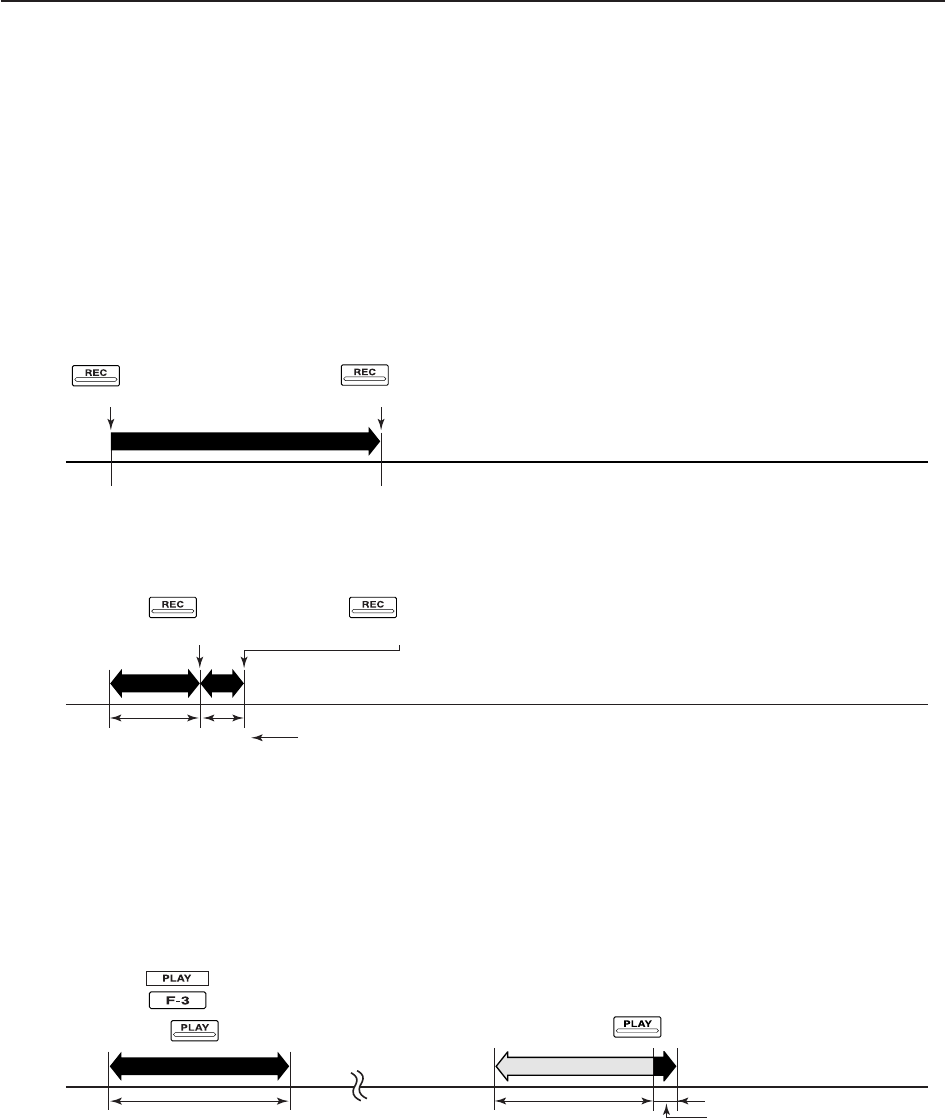
■About digital voice recording
The IC-R9500 has two types of digital voice recorders.
One is a regular voice recorder for which a continuous
long recording is available.
And the other is a short recorder which temporarily
stores the previous period. A maximum message
length of 30 sec. can be recorded into a RAM.
• Example— Regular recording
• Example— Short recording
• Playing back the all contents for short recording • Playing back the end of 5 sec.* for short recording
Push for 1 sec.
(starts recording)
Or, push for 1 sec.
Push for 1 sec.
(stops recording)
Push momentarily
(starts recording) Push momentarily
(starts recording)
Push momentarily.
Push momentarily.
15 sec.
(default)
30 sec. (max.) Not playing back Play back (5 sec.; default)
3 sec.
Push [REC] momentarily
records the contents of
the previous 15 sec.*
When [REC] is pushed momentarily again within 15 sec.*
from the last [REC] operation, all the contents between
[REC] operations will be recorded.
*The recording time period can be changed with “Short Rec Time” in voice set mode (p. 6-6).
*The playing back time period can be changed with
“Short Play Time” in voice set mode (p. 6-6).
NOTE: The contents will be overwritten, and previous recorded
contents are erased.
NOTE: The recording time period differ depends on the recording
sound quality and memory capacity.
6VOICE RECORDER FUNCTIONS
6-3
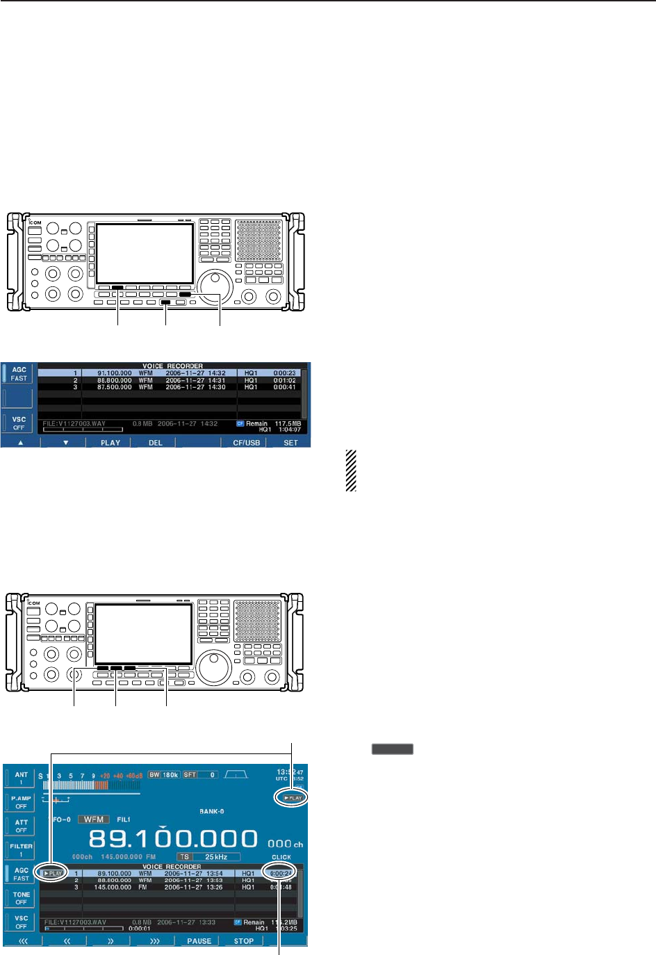
■Recording received audio
This voice recorder records not only the received
audio, but also information such as operating fre-
quency, mode, and the recording time for your future
reference.
DRegular recording
qPush [EXIT/SET] several times to close a multifunc-
tion screen, if necessary.
wSelect the desired mode.
ePush [F-2•VOICE] to call up the voice recorder
screen.
• Push and hold [F-6•CF/USB] for 1 sec. once or twice to
select the CF card or USB-Memory, when USB memory
is Inserted.
• The recording sound quality can be set in voice set
mode. (p. 6-6)
rPush and hold [REC] for 1 sec. to start recording.
• The operating frequency, mode and current date/time
are programmed as the memory names automatically.
tPush and hold [REC] for 1 sec. to stop recording.
yPush [EXIT/SET] to exit the voice recorder screen.
If you do not change any recording setting, you can
start or stop recording from the normal screen, just
push and hold [REC] for 1 sec.
■Playing the recorded audio
DRegular playing
qPush [EXIT/SET] several times to close a multifunc-
tion screen, if necessary.
wPush [F-2•VOICE] to call up the voice recorder
screen.
• Push and hold [F-6•CF/USB] for 1 sec. once or twice to
select the CF card or USB-Memory, when USB memory
is Inserted.
ePush [F-1•Y] or [F-2•Z] to select the desired voice
memory to playback.
rPush [F-3•PLAY] to start playback.
• “ ” indicators appear on the voice recorder
screen and display’s right edge, and the timer counts
down.
• Push [F-1•<<<] when you want to rewind for 15 sec.
• Push [F-2•<<] when you want to rewind for 5 sec.
• Push [F-3•>>] when you want to fast forward for 5 sec.
• Push [F-4•>>>] when you want to fast forward for 15 sec.
• Push and hold above keys to continue rewinding or fast
forwarding, respectively.
• Push [F-5•PAUSE] when you want to pause playing
back.
tPush [F-6•STOP] to stop playback, if desired.
• Playback is terminated automatically when all of the
recorded contents in the channel are played.
yPush [EXIT/SET] to exit the voice recorder screen.
≈PLAY
Appear
Counts down
[F-1•Y] [F-2•Z] [F-3•PLAY]
[EXIT/SET][REC][F-2•VOICE]
6
VOICE RECORDER FUNCTIONS
6-4
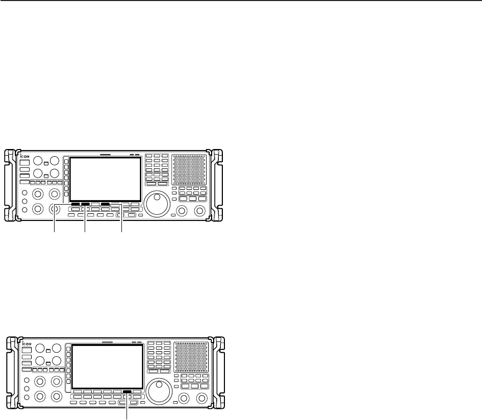
■Erasing the recorded contents
The recorded contents can be erased independently
by channel.
qCall up the voice recorder screen.
• Push and hold [F-6•CF/USB] for 1 sec. once or twice to
select the CF card or USB-Memory, when USB memory
is Inserted.
wPush [F-1•Y] or [F-2•Z] to select the desired voice
memory to be erased.
ePush and hold [F-4•DEL] for 1 sec. to erase the con-
tents.
rPush [EXIT/SET] to exit the voice recorder screen.
■Select the CF memory card or USB-Memory
The voice recorder can record into CF memory card or
USB-Memory, when USB-Memory is inserted.
qCall up the voice recorder screen.
wPush and hold [F-6•CF/USB] for 1 sec. to select the
desired CF card or USB-Memory.
eOperate the voice recorder as desired.
rPush [EXIT/SET] to exit the voice recorder screen.
[F-6•CF/USB]
[F-1•Y] [F-2•Z] [F-4•DEL]
6VOICE RECORDER FUNCTIONS
6-5
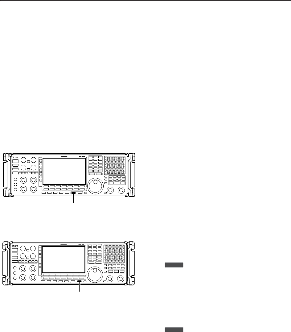
■Short recording
To record the receiving signal contents temporarily and
immediately, short recording is available. This short
recording function records the 15 sec. (max.) of audio
prior to when [REC] is pushed into RAM. Content is
only saved when the receiver’s power is ON and lost
when power is removed.
This short recording is useful when you miss hearing
important information from the receiver, you can listen
to the important information once more. This function
can be used while you are recording into CF memory
card or USB-Memory as regular recording.
DRecording
➥Push [REC] momentarily to save the previous
15 sec. audio.
• No indication appears.
• The recordable time period can be set in voice set mode.
(p. 6-6)
DPlaying back
• Short time play
➥Push [PLAY] momentarily to play back the last
5 sec. of the short recording audio.
• “ ” indicator appears on the display’s right edge.
• Playback is terminated automatically when all of the
recorded contents, or after 5 sec.
• The playback time period can be set in voice set mode.
(p. 6-6)
• Full time play
➥Push and hold [PLAY] for 1 sec. to play back the
short recording audio for full time.
• “ ” indicator appears on the display’s right edge.
• Playback is terminated automatically when all of the
recorded contents are played.
≈PLAY
≈PLAY
[PLAY]
[REC]
6
VOICE RECORDER FUNCTIONS
6-6
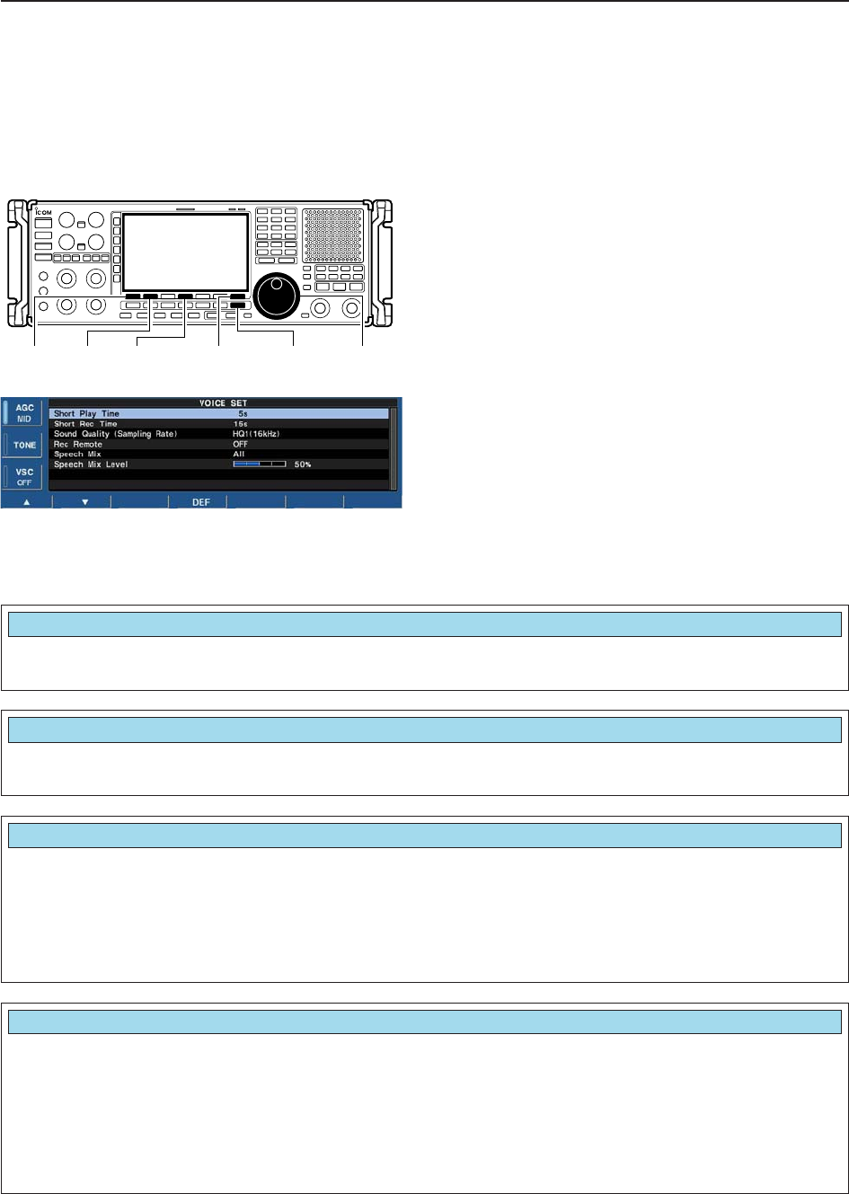
■Voice set mode
Sets the automatic monitor function, short play and
normal recording times for voice recorder.
qPush [EXIT/SET] several times to close a multifunc-
tion screen, if necessary.
wPush [F-2•VOICE] to call up the voice recorder
screen.
ePush [F-7•SET] to enter the voice set mode screen.
rPush [F-1•Y] or [F-2•Z] to select the desired item.
tRotate main dial to set the desired condition or
value.
• Push and hold [F-4•DEF] for 1 sec. to select the default
condition or value.
yPush [EXIT/SET] to exit the voice set mode screen.
[F-1•Y] [F-2•Z] [F-4•DEF] [EXIT/SET][F-7•SET] Main dial
6VOICE RECORDER FUNCTIONS
Set the desired time period for the short play back
(when [PLAY] is pushed momentarily). • 3 to 10 sec. in 1 sec. steps can be set.
(default: 5 sec.)
Short Play Time
5s
Set the desired time period for one-touch recording
(when [REC] is pushed momentarily). • 5 to 30 sec. in 1 sec. steps can be set.
(default: 15 sec.)
Short Rec Time
15s
Set the recording sound quality. The sampling rate
setting is expressed in samples per second, and de-
termines the sound quality.
Although a higher sampling rate provides a better
quality sound than a lower sampling rate, the file size
becomes larger.
• SQ1 (8kHz), SQ2 (12kHz), HQ1 (16KHz), HQ2
(24kHz), SHQ (48kHz) can be set.
(default: HQ1(16kHz))
Sound Quality (Sampling Rate)
HQ1(16kHz)
Turns the recording control signal ON or OFF. (de-
fault: OFF) • OFF : Continues recording even when received
signal disappears or squelch closes. (de-
fault)
• ON : Records only when received signal ap-
pears or squelch opens and stops record-
ing when received signal disappears or
squelch closes.
REC Remote
OFF
6-7
6
VOICE RECORDER FUNCTIONS
Selects the recording the speech audio from “All,”
“Operation” and “OFF.” • All : Records the speech audio when speech
operation is performed from the front
panel or scan stops if “REC SPEECH”
setting is ON in the others set mode (p.
11-11).
• Operation: Records the speech audio when speech
operation is performed from the front
panel.
• OFF : No recording of the speech audio.
SPEECH Mix
All
Sets the recording speech audio level from 0 to 100%
in 1% steps. (default: 50%) • 0% : Mutes the speech audio.
•
•
•
• 50% : Same level as receive audio. (default)
•
•
•
• 100% : Mutes the receive audio.
Speech Mix Level
50%
■Voice set mode (continued)

7-1
MEMORY OPERATION Section 7
■Memory channels ……………………………………………………… 7-2
■Memory channel selection …………………………………………… 7-3
DUsing the [M-CH]/[BANK] selectors ……………………………… 7-3
DUsing the keypad …………………………………………………… 7-3
■Memory channel programming ……………………………………… 7-4
DProgramming in VFO mode ………………………………………… 7-4
DProgramming in memory mode …………………………………… 7-4
■Frequency transferring ………………………………………………… 7-5
DTransferring in VFO mode ………………………………………… 7-5
DTransferring in memory mode ……………………………………… 7-5
■Memory names ………………………………………………………… 7-6
DEditing (programming) memory names …………………………… 7-6
■Memory clearing ………………………………………………………… 7-6
■Memory list screen ……………………………………………………… 7-7
DSelecting a memory channel using the memory list screen …… 7-7
DConfirming programmed memory channels ……………………… 7-7
DMemory bank set …………………………………………………… 7-8

7-2
■Memory channels
The receiver has 1220 memory channels. Memory
mode is very useful for quickly changing to often-used
frequencies.
All 1220 memory channels are tuneable which means
the programmed frequency can be tuned temporarily
with the main dial, etc. in memory mode.memory chan-
nel.
7MEMORY OPERATION
MEMORY
CHANNEL
Regular memory
channels
Auto write mem-
ory channels
Skip memory
channels
Scan edge mem-
ory
channels
MEMORY
CHANNEL
NUMBER
0–999
(0–999)
A00–A99
(1000–1099)
S00–S99
(1100–1199)
P0A–P9B
(1200–1219)
CAPABILITY
For normal use. Frequency, mode, tuning
step, name, P.AMP/ATT information and etc.
can be programmed.
Frequencies detected during auto memory
write scan are memorized into this bank in
sequence. Mode and tuning step are written
at the same time. Note that when “Auto MW
Scan Memory Clear” in scan set mode is set
as “ON” and auto write scan is started, all
memories in this bank are cleared.
Undesired signals such as from beacons, con-
trol-coded signals, etc., can be programmed
to be skipped during programmed scan and
auto memory write scan. When [MW] is
pushed and held for 1 sec. while scan is
paused, the displayed frequency is pro-
grammed into this bank regardless of the
selected bank.
Memorize scan edge frequencies. 10 pairs of
scan edges (P0A to P9B) are programmable
(upper and lower scan edges). Mode and tun-
ing step are automatically equalized to the last
programmed channel in a pair.
TRANSFER
TO VFO
YES
YES
YES
YES
OVER-
WRITING
YES
YES
YES
YES
CLEAR
YES
YES
YES
YES
7-3
■Memory channel selection
DUsing the [M-CH]/[BANK] selectors qPush [MEMO] to select memory mode.
wRotate [BANK] to select the desired memory bank.
eRotate [M-ch] to select the desired memory channel.
rTo return to VFO mode, push [VFO].
• Last operated VCO appears.
• Or push numeral key (0–9) and [VCO] to return to the
desired VCO.
✔
Bank limit function
While rotating the [M-CH] selector, memory channels
are selectable in the current bank only (Bank limit ON);
or selectable from all banks (Bank limit OFF).
➥Push and hold [MEMO] for 1 sec. to turn the bank
limit function ON (default) or OFF.
• “BANK” indicator appears or disappears.
DUsing the keypad
qPush [MEMO] to select memory mode.
wPush the desired memory channel number using the
keypad.
• Enter 0 to 999 to select the regular memory channels.
• Enter 1000 to 1099 to select the auto write memory
channels A00 to A99. (Push “10” before entering mem-
ory number instead of A.
• Enter 1100 to 1199 to select the skip memory channels
S00 to S99. (Push “11” before entering memory number
instead of S.
• Enter 1200 to 1219 to select the scan edge channels
P0A to P9B.
ePush [MEMO] to select the desired memory chan-
nel.
[EXAMPLE]
To select the memory channel 3;
- Push [3], then push [MEMO].
To select the memory channel 520;
- Push [5], [2], [0], then push [MEMO].
To select the auto write memory channel A24;
- Push [1], [0], [2], [4], then push [MEMO].
To select the skip channel S65;
- Push [1], [1], [6], [5], then push [MEMO].
To select the scan edge channel P3B;
- Push [1], [2], [0], [7], then push [MEMO].
[MEMO] Keypad
[MEMO] [M-CH][BANK]
7
MEMORY OPERATION
1200 (P0A)
1201 (P0B)
1202 (P1A)
1203 (P1B)
1204 (P2A)
1205 (P2B)
1206 (P3A)
1207 (P3B)
1208 (P4A)
1209 (P4B)
1210 (P5A)
1211 (P5B)
1212 (P6A)
1213 (P6B)
1214 (P7A)
1215 (P7B)
1216 (P8A)
1217 (P8B)
1218 (P9A)
1219 (P9B)
7-4
7MEMORY OPERATION
■Memory channel programming
Memory channel programming can be performed ei-
ther in VFO mode or in memory mode.
DProgramming in VFO mode
qSet the desired frequency, operating mode and fil-
ter width in VFO mode.
wRotate [M-CH] (and [BANK]) to select the desired
memory channel.
• Memory list screen is convenient for selecting the de-
sired channel.
• Memory channel contents appear in the memory chan-
nel readout (below the frequency readout).
• “--.---.--” appears if the selected memory channel is a
blank channel (and does not have contents).
ePush and hold [MW] for 1 sec. to program the dis-
played frequency, operating mode, etc., into the
memory channel.
DProgramming in memory mode
qSelect the desired memory channel with [M-CH] in
memory mode.
• Memory channel contents appear in the memory chan-
nel readout (below the frequency readout).
• “--.---.--” appears if the selected memory channel is a
blank channel (and does not have contents).
wSet the desired frequency and operating mode in
memory mode.
• To program a blank channel, use direct frequency entry
with the keypad.
ePush and hold [MW] for 1 sec. to program the dis-
played frequency and operating mode into the mem-
ory channel.
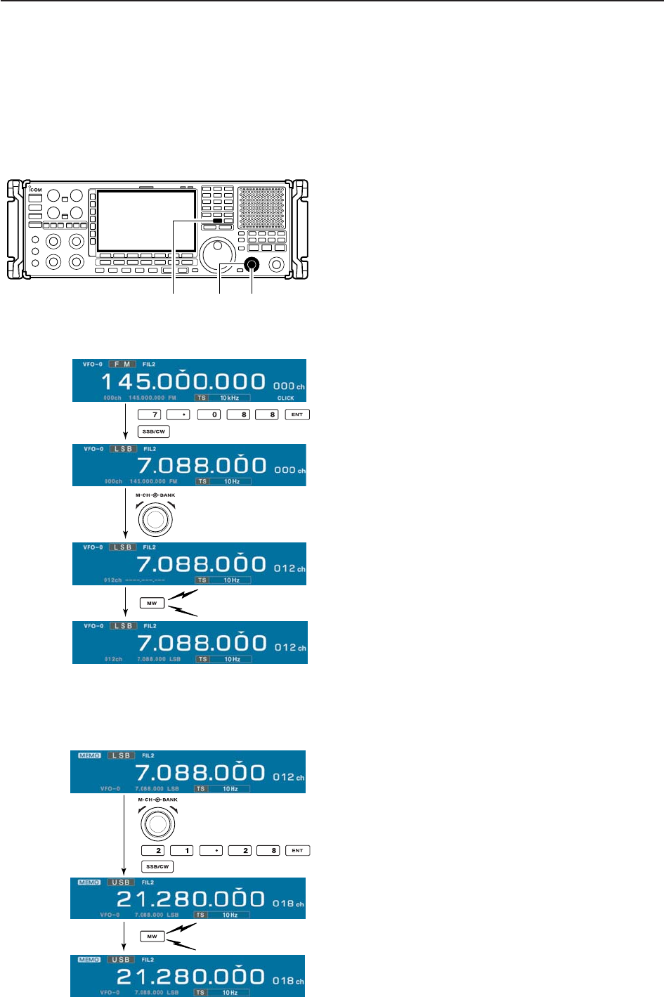
[MW] [M-CH][BANK]
Push for 1 sec.
Beep
Beep
Beep
Rotate
[EXAMPLE]: Programming 7.088 MHz/LSB into mem-
ory channel 12.
Push for 1 sec.
Beep
Beep
Beep
Rotate
[EXAMPLE]: Programming 21.280 MHz/USB into mem-
ory channel 18.
7-5
7
MEMORY OPERATION
■Frequency transferring
The frequency and operating mode in a memory chan-
nel can be transferred to the VFO.
Frequency transferring can be performed in either VFO
mode or memory mode.
DTransferring in VFO mode
This is useful for transferring programmed contents to
VFO.
qSelect VFO mode with [VFO].
wSelect the memory channel to be transferred with
[M-CH] (and [BANK]).
• Memory list screen is convenient for selecting the de-
sired channel.
• Memory channel contents appear in the memory chan-
nel readout (below the frequency readout).
• “--.---.--” appears if the selected memory channel is a
blank channel. In this case transferring is impossible.
ePush and hold [M≈V] for 1 sec. to transfer the fre-
quency and operating mode.
• Transferred frequency and operating mode appear on
the frequency readout.
DTransferring in memory mode
This is useful for transferring frequency and operating
mode while operating in memory mode.
When you have changed the frequency or operat-
ing mode in the selected memory channel:
•Displayed frequency, mode and filter setting are
transferred.
•Programmed frequency and mode in the memory
channel are not transferred, and they remain in the
memory channel.
qSelect the memory channel to be transferred with
[M-CH] (and [BANK]) in memory mode.
• And, set the frequency or operating mode if required.
wPush and hold [M≈V] for 1 sec. to transfer the fre-
quency and operating mode.
• Displayed frequency and operating mode are transferred
to the VFO.
eTo return to VFO mode, push [VFO] momentarily.
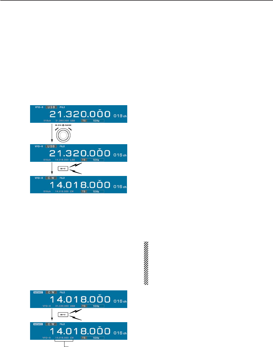
TRANSFERRING EXAMPLE IN VFO MODE
Operating frequency : 21.320 MHz/USB (VFO)
Contents of M-ch 16 : 14.018 MHz/CW
TRANSFERRING EXAMPLE IN MEMORY MODE
Operating frequency : 21.320 MHz/USB (M-ch 16)
Contents of M-ch 16 : 14.018 MHz/CW
Push for 1 sec.
Beep
Beep
Beep
Rotate
Push for 1 sec.
Beep
Beep
Beep
Programmed contents appear.
7-6
7MEMORY OPERATION
■Memory names
All memory channels (including scan edges) can be
tagged with alphanumeric names of up to 10 charac-
ters each.
Capital letters, small letters, numerals, some symbols
(! # $ % & ¥ ? " ’ ` ^ + – ✱/ . , : ; = < > ( ) [ ] { } | _ ~@)
and spaces can be used.
DEditing (programming) memory names
qPush [EXIT/SET] several times to close a multifunc-
tion screen, if necessary.
wPush [F-4•MEMORY] to select memory list screen.
eSelect the desired memory channel.
rPush [F-4•NAME] to edit memory channel name.
• A cursor appears and blinks.
• Memory channel names of blank channels cannot be
edited.
tInput the desired character by rotating the main dial
or by editing the keypad for number input.
• Push [ABC] or [abc] to toggle capital and small letters.
• Push [123] or [Symbol] to toggle numerals and symbols.
• Push [F-1•Ω] or [F-2•≈] for cursor movement.
• Push [F-3•DEL] to delete the selected character.
• Push [F-4•SPACE] to input a space.
• Using the receiver’s keypad, [0]–[9], can also enter nu-
merals.
yPush [EXIT/SET] to input and set the name.
• The cursor disappears.
uRepeat steps eto yto program another memory
channel’s name, if desired.
iPush [EXIT/SET] to exit memory list screen.
■Memory clearing
Any unused memory channels can be cleared. The
cleared memory channels become blank channels.
qSelect memory mode with [MEMO].
wPush [F-4•MEMORY] to select memory list screen.
eSelect the desired memory channel with [M-CH].
rPush and hold [M-CL] for 1 sec. to clear the con-
tents.
• The programmed frequency and operating mode disap-
pear.
tTo clear other memory channels, repeat steps e
and r.
Push for 1 sec.
Beep
Beep
Beep
(CLR)
[M-CL]
[F-1•Ω] [F-2•≈][F-4•SPACE]
[F-3•DEL]
Keypad[ABC]/[abc] [123]/[Symbol]
7-7
7
MEMORY OPERATION
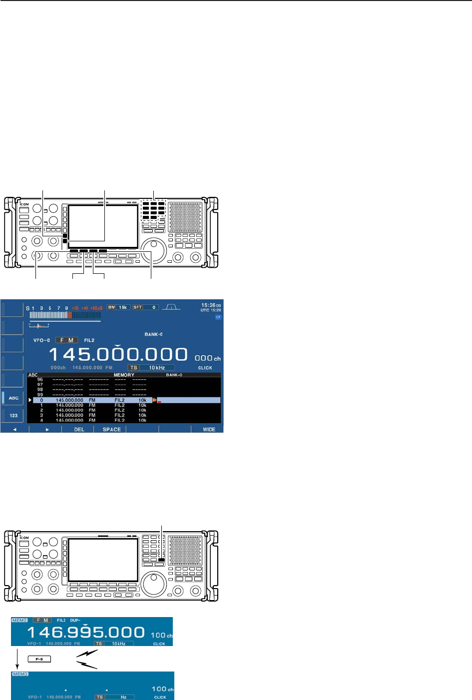
■Memory list screen
The memory list screen simultaneously shows 9 mem-
ory channels and their programmed contents. 15 mem-
ory channels can be displayed in the wide memory list
screen.
You can select a desired memory channel from mem-
ory list screen.
DSelecting a memory channel using the memory list screen
qPush [EXIT/SET] several times to close a multifunc-
tion screen, if necessary.
wPush [F-4•MEMORY] to select memory list screen.
• [F-7•WIDE] switches the standard and wide screens.
eWhile pushing [F-1•ROLL], rotate the main dial to
select the desired memory channel.
• [M-CH] can also be used.
rPush [EXIT/SET] to exit memory list screen.
• Memory list screen
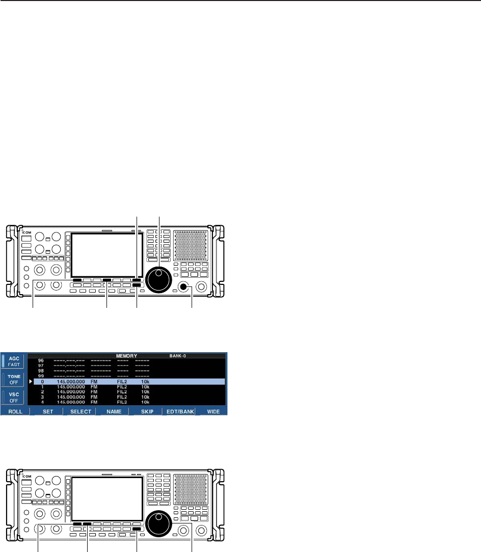
DConfirming programmed memory channels
qSelect memory list screen as described above.
wWhile pushing [F-1•ROLL], rotate the main dial to
scroll the screen.
ePush [F-2•SET] to select the highlighted memory
channel, if desired.
•“≈” appears beside the selected memory channel num-
ber in the memory list screen and the selected memory
channel contents are displayed below the frequency
readout.
rPush [EXIT/SET] to exit memory list screen.
Main dial
[F-1•ROLL] [F-2•SET] [EXIT/SET]
[M-CH]
Main dial
[F-1•ROLL] [F-4•MEMORY] [EXIT/SET]
[F-7•WIDE]
7-8
7MEMORY OPERATION
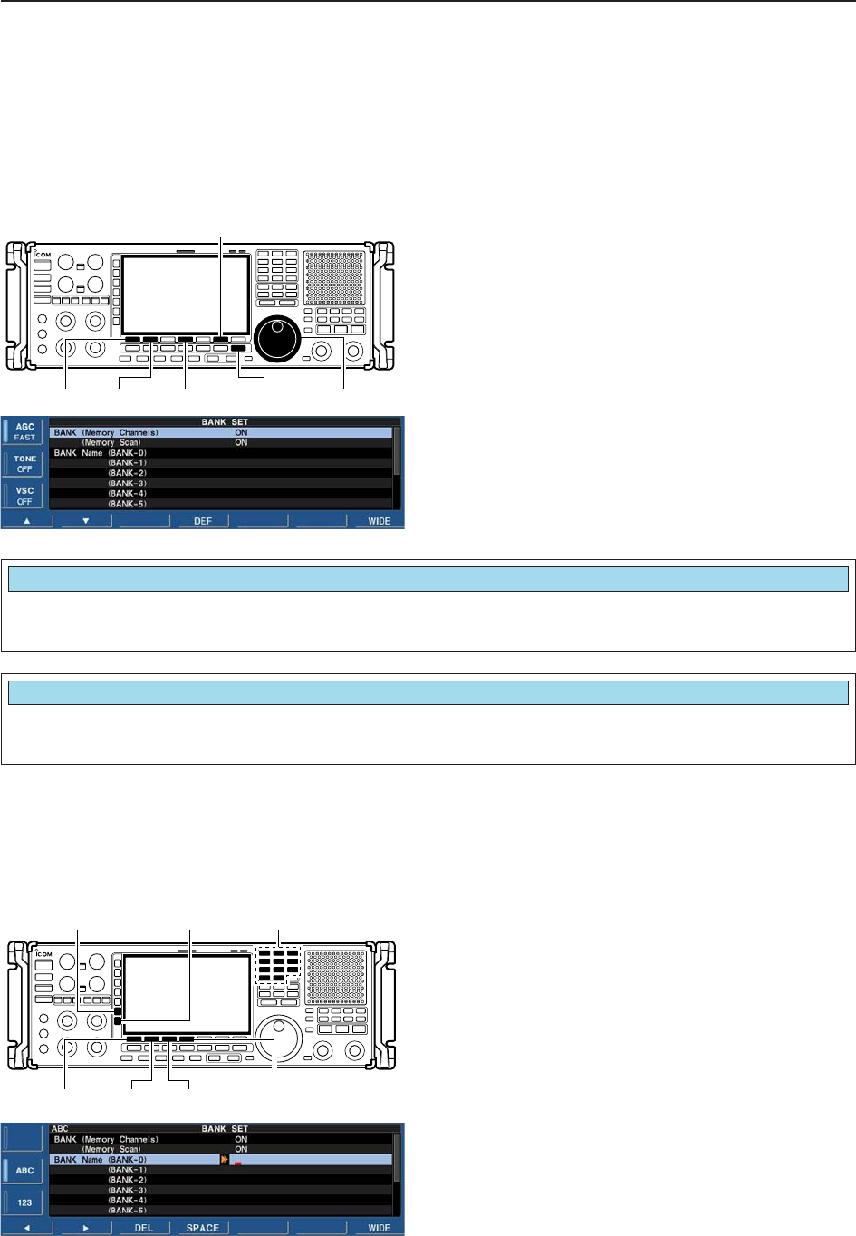
DMemory bank set
Setting bank limit function for memory channel selec-
tion, for memory scan can be set in bank set mode or
programming bank name.
qSelect memory list screen as described at previous
page.
wPush and hold [F-6•EDT/BANK] for 1 sec. to display
the memory bank set mode.
ePush [F-1•Y] or [F-2•Z] to select the desired item.
rRotate the main dial to set the desired setting.
• Push and hold [F-4•DEF] for 1 sec. to select a default
value.
tPush [EXIT/SET] to return to memory list screen.
Main dial
[F-1•Y] [F-2•Z][EXIT/SET]
[F-6•EDT/BANK]
[F-4•DEF]
Selects the bank limit function for memory channel
selection from ON and OFF. (default: ON)
BANK (Memory Channels)
ON
Selects the bank limit function for memory scan from
ON and OFF. (default: ON)
BANK (Memory Scan)
ON
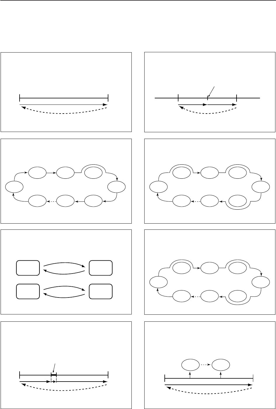
• Programming bank names
Capital letters, small letters, numerals, some symbols
(! # $ % & ¥ ? " ’ ` ^ + – ✱/ . , : ; = < > ( ) [ ] { } | _ ~@)
and spaces can be used for bank name programming.
qPush [F-1•Y] or [F-2•Z] to select the desired mem-
ory bank.
wPush [F-5•EDIT] to edit memory bank name.
• A cursor appears and blinks.
eInput the desired character by rotating the main dial
or by editing the keypad for number input.
• Push [ABC] or [abc] to toggle capital and small letters.
• Push [123] or [Symbol] to toggle numerals and symbols.
• Push [F-1•Ω] or [F-2•≈] for cursor movement.
• Push [F-3•DEL] to delete the selected character.
• Push [F-4•SPACE] to input a space.
• Using the receiver’s keypad, [0]–[9], can also enter nu-
merals.
rPush [EXIT/SET] to input and set the name.
• The cursor disappears.
tRepeat steps qto rto program another memory
bank’s name, if desired.
yPush [EXIT/SET] to return to memory list screen.
[F-1•Ω] [F-2•≈][F-4•SPACE]
[F-3•DEL]
Keypad[ABC]/[abc] [123]/[Symbol]

8-1
SCANS Section 8
■Scan types ……………………………………………………………… 8-2
■Preparation ……………………………………………………………… 8-3
■Voice squelch control function ………………………………………… 8-3
■Scan set mode ………………………………………………………… 8-4
■Priority scan ……………………………………………………………… 8-5
DSetting ………………………………………………………………… 8-5
DPriority scan operation ……………………………………………… 8-5
■Programmed scan ……………………………………………………… 8-6
DSetting ………………………………………………………………… 8-6
DProgram scan operation …………………………………………… 8-7
■∂F scan ………………………………………………………………… 8-8
DSetting ………………………………………………………………… 8-8
D∂F scan operation …………………………………………………… 8-8
■Fine programmed scan/fine ∂F scan operation……………………… 8-9
■Auto memory write scan operation…………………………………… 8-10
■Memory scan …………………………………………………………… 8-11
DSetting ……………………………………………………………… 8-11
DMemory scan operation …………………………………………… 8-11
DProgramming the select memory scan setting ………………… 8-12
DSelect memory scan operation …………………………………… 8-13
DMode select memory scan operation …………………………… 8-14
■Skip scan ……………………………………………………………… 8-15
DSpecifying skip channels ………………………………………… 8-15
DProgramming skip frequencies (for programming scan) ……… 8-15
DSkip scan setting …………………………………………………… 8-15
■Tone scan ……………………………………………………………… 8-16
■Scan resume condition………………………………………………… 8-17
■Scan speed …………………………………………………………… 8-18
■Scan delay ……………………………………………………………… 8-18
8-2
■Scan types
PROGRAMMED SCAN
Repeatedly scans between two scan edge frequencies
(scan edge memory channels PxA and PxB).
This scan operates in both VFO and memory modes.
SELECT MEMORY SCAN
Repeatedly scans all or one of 9 select memory channels.
∂F SCAN
Repeatedly scans within ∂F span.
This scan operates in memory mode.This scan operates in memory mode.
This scan operates in both VFO and memory modes.
Scan
Scan edge
PxA or PxB Scan edge
PxB or PxA
Jump
MEMORY SCAN
Repeatedly scans all programmed memory channels.
Mch 1
★1Mch 5
★1
Mch 2
★2Mch 3
★1Mch 4
Mch 6
★3
Mch 7
Mch 99
★1
Mch 1
★1Mch 5
★1
Mch 2
★2Mch 3
★1Mch 4
Mch 6
★3
Mch 7
★1
Mch 99
★1
Blank channel Blank channel
Scan
Scan edge
PxA or PxB Scan edge
PxB or PxA
Jump
ScanScan
–∂F frequency +∂F frequency
Start frequency
Jump
FINE SCAN
Scans in 10 Hz steps when squelch is open (around the
signal) while program scan or ∂F scan.
This scan operates in both VFO and memory modes.
AUTO MEMORY WRITE SCAN
Auto memory write scan operates in the same way as
programmed scan. However, when a signal is received,
the received frequency is automatically written into a
memory channel in the auto write bank.
This scan operates in both VFO and memory modes.
Scan Pause
Program
Scan edge
PxA or PxB Scan edge
PxB or PxA
Jump
Squelch open
PRIORITY SCAN
Continuously switches between monitoring displayed
frequency and specified memory channel (priority
channel).
This scan operates in both VFO and memory modes.
Memory
Channel
Priority Channel
Priority Channel
*“★1,” “★2” and “★3” show that the channel
is specified as the select memory. *“★1,” “★2” and “★3” show that the channel
is specified as the select memory.
MODE SELECT MEMORY SCAN
Repeatedly scans a selected mode (ignoring other
modes) while memory scanning.
This scan operates in memory mode.
Pause
Program
Mch 1
Mch A0
Mch A99
Mch 5
Mch 2 Mch 3 Mch 4
Mch 6Mch 7Mch 99
VFO
Frequecy
Memory
Channel
Memory
Channel
or
USB CW
FM
FM
FM
FSKFMFM
(10 Hz steps)
8SCANS
8-3
8
SCANS
■Preparation
• Channels
For programmed scan:
Program scan edge frequencies into scan edge mem-
ory channels PxA and PxB.
For
∂
F scan:
Set the ∂F span (∂F scan range) in the scan screen.
For memory scan:
Program 2 or more memory channels except scan
edge memory channels.
For select memory scan:
Designate 2 or more memory channels as select mem-
ory channels. To designate the channel as a select
memory channel, choose a memory channel, then
push [F-3•SELECT] in the scan screen (memory
mode) or in the memory list screen.
• Scan resume ON/OFF
You can select the scan to resume or cancel when a
signal is detected. Scan resume ON/OFF must be set
before activating a scan. See p. 8-17 for ON/OFF set-
ting and scan resume condition details.
• Scan speed
Scan speed can be adjusted by [SPEED] controller.
See p. 8-18 for details.
• Squelch condition
SQUELCH
CLOSED
SQUELCH
OPEN
Scan stops when a signal is detected.
If you set ‘SCAN RESUME’ to ‘DELAY,’ the
scan pauses according to [DELAY] control
when detecting a signal, then resumes.
When a signal disappears while scan is
paused, scan resumes 2–20 sec. later.
The scan continues
until it is stopped
manually, and does
not pause even if it
detects signals.
Scan pauses on
each channel when
the scan resume is
ON; not applicable
when OFF.
SCAN PROGRAMMED
STARTS SCAN MEMORY SCAN
WITH
■Voice squelch control function
This function is useful when you don’t want unmodu-
lated signals pausing or cancelling a scan. When the
voice squelch control function is activated, the receiver
checks received signals for voice components.
If a receiver signal includes voice components, and the
tone of the voice components changes within 1 sec.,
scan pauses (or stops). If the received signal includes
no voice components or the tone of the voice compo-
nents does not change within 1 sec., scan resumes.
➥While a phone mode (FM, WFM, SSB, AM) is se-
lected, push [VSC] to switch the VSC (Voice
Squelch Control) function ON and OFF.
• “VSC” appears when the function is activated.
• The VSC function activates for any scan.
• The VSC function resumes the scan on unmodu-
lated signals, regardless of whether the scan re-
sume condition is set to ON or OFF.
[VSC]
8-4
8SCANS
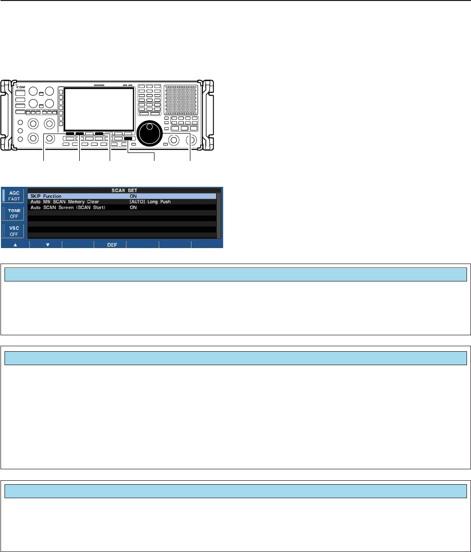
■Scan set mode
This set mode is used to set the skip scan setting,
memory clear condition for auto memory write chan-
nels and appearing scan screen setting.
qPush [F-5•SCAN] to select scan screen.
wPush [F-7•SET] to select scan set mode.
ePush [F-1•Y] or [F-2•Z] to select the desired item.
rRotate the main dial to select the desired condition.
• Push and hold [F-4•DEF] for 1 sec. to select the default
setting.
tPush [EXIT/SET] to return to scan menu.
[F-1•Y] [F-2•Z] [F-4•DEF] [EXIT/SET] Main dial
Select the skip scan function ON or OFF. • ON : Scan skips the programmed memory channel
in the skip memory bank while scanning (de-
fault)
• OFF : Skip function OFF
SKIP Function
ON
Set the clearing condition for the auto memory write
scan’s memories channels. • ON : Auto memory channels are cleared when
starting the auto memory write scan.
• [AUTO] Long Push
: Auto memory channels are cleared when
pushing and holding [AUTO]. (default)
• OFF : Auto memory channels must be cleared man-
ually and auto memory write scan stops when
100 channels (A00 to A99) are wrote.
Auto MW SCAN Memory Clear
[AUTO] Long Push
Set the automatic scan screen ON function when
starting a scan. • ON : When starting a scan, scan screen appears
automatically. (default)
• OFF : Scan screen does not appear until [F-
5•SCAN] is pushed.
Auto SCAN Screen (SCAN Start)
ON
8-5
8
SCAN
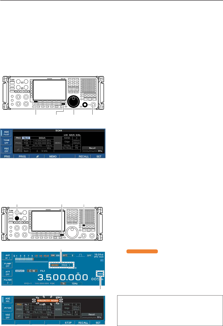
■Priority scan
Priority scan monitors a specified frequency (the prior-
ity channel) once every 1–16 sec. (programmable) dur-
ing any operation, such as receiving, scanning other
channels, etc. A total of 10 priority channels can be
programmed.
DSetting
qPush [EXIT/SET] several times to close a multifunc-
tion screen, if necessary.
wPush [F-5•SCAN] to select scan setting screen.
ePush [F-1•PRIO] once to enter priority channel se-
lection.
rRotate the main dial to select priority channel num-
ber.
• No.1 to No.9 are available.
tPush [F-1•PRIO], then rotate main dial to select the
desired memory channel as priority channel.
yPush [F-1•PRIO] to set the priority scan.
uSet the desired VFO or memory channel.
[F-1•PRIO] [EXIT/SET] Main dial [BANK]
DPriority scan operation
qPush [EXIT/SET] several times to close a multifunc-
tion screen, if necessary.
wSelect the desired VFO or memory channel.
eSelect the desired operating mode when VFO is se-
lected.
• The operating mode can also be changed while scan-
ning.
rSet [SQUELCH] control open or closed.
• See page 9-2 for squelch condition.
tPush [PRIO] to start the priority scan.
• “ ” blinks while scan screen is dis-
played.
• “PRIO” blinks while monitoring the priority channel.
yTo cancel the scan, push [PRIO].
• Pushing [F5•STOP] also cancels the scan.
• Pushing [EXIT/SET] closes the scan screen, if displayed.
PRIORITY SCAN
Scan indicator and Priority scan number appear
Priority channel indicator
[EXIT/SET] [PRIO][SQUELCH]
• Monitoring the Priority channel
qPush and hold [PRIO] for 1 sec. to monitor the
priority channel.
• “PRIO” blinks while monitoring the priority channel.
wTo cancel the monitoring, push [PRIO].
8-6
8SCANS
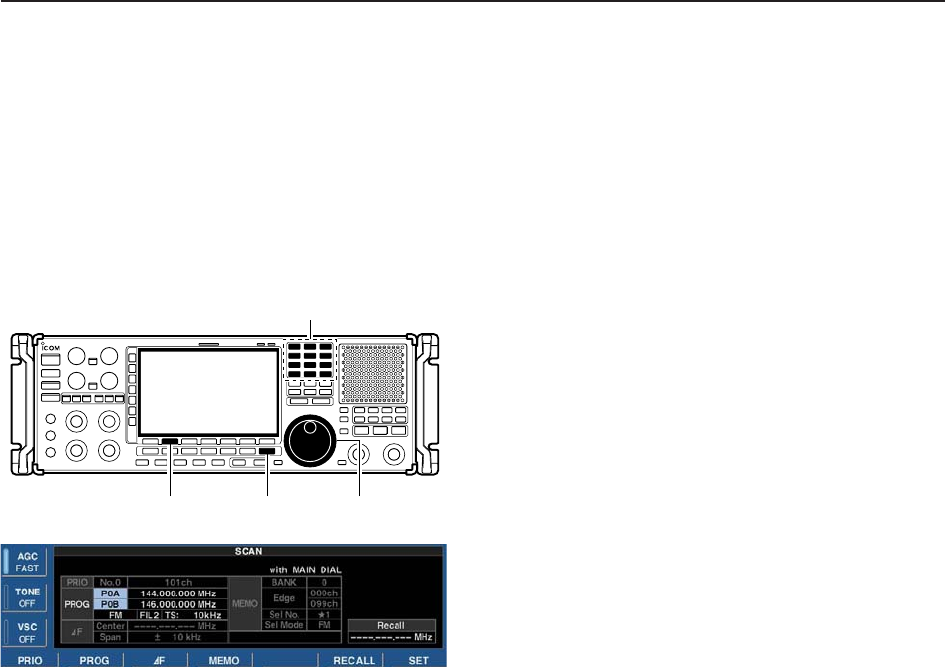
■Programmed scan
Programmed scan searches for signals within a speci-
fied frequency range, using the selected tuning step in-
crements. The result is like ‘automatically’ rotating of
the main dial.
DSetting
qPush [EXIT/SET] several times to close a multifunc-
tion screen, if necessary.
wPush [F-5•SCAN] to select scan setting screen.
ePush [F-2•PROG] once to enter the programmed
scan selection mode.
rRotate the main dial to select the desired scan
edges.
• A pair of P0A and P0B to P9A and P9B are available.
tPush [F-2•PROG] to enter the start edge frequency
programming, then edit the desired frequency using
the keypad.
yPush [F-2•PROG] to enter the end edge frequency
programming, then edit the desired frequency using
the keypad.
uPush [F-2•PROG] to enter the operating mode se-
lection, then rotate main dial to select the desired
operating mode.
iPush [F-2•PROG] to enter the filter selection, then
rotate main dial to select the desired filter.
oPush [F-2•PROG] to enter the tuning steps selec-
tion, then rotate main dial or edit using the keypad to
select the desired tuning steps.
!0 Push [F-2•PROG] to set the programmed scan.
[F-2•PROG] [EXIT/SET] Main dial
Keypad
8-7
8
SCANS
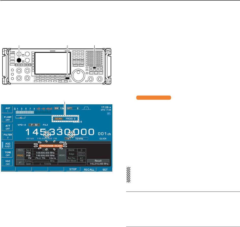
DProgrammed scan operation
qPush [EXIT/SET] several times to close a multifunc-
tion screen, if necessary.
wSelect the desired VFO or memory channel.
eSelect the desired operating mode.
• The operating mode can also be changed while scan-
ning.
rSet [SQUELCH] control open or closed.
• See page 8-3 for squelch condition.
tPush [PROG] to start the programmed scan.
• Scan screen appears.
• “ ” and decimal points blink while
scanning.
• Push numeral key (0–9) to change to the other edges.
yWhen the scan detects a signal, the scan stops,
pauses or ignores it depending on the resume set-
ting and the squelch condition.
uTo cancel the scan, push [PROG].
• Pushing [F5•STOP] also cancels the scan.
• Pushing [EXIT/SET] closes the scan screen.
iPush and hold [F-6•RECALL] for 1 sec. to recall the
frequency that is set before starting the scan, if de-
sired.
If the same frequencies are programmed into the
scan edge memory channel PxA and PxB, pro-
grammed scan does not start.
✔
For your convenience
Ten programmed scans can be selected directly from
the keypad. Then the scan starts immediately.
➥Push numeral key (0–9) then push [PROG] to start
the desired programmed scan.
PROGRAM SCAN
Scan indicator and Program scan number appear
[EXIT/SET][SQUELCH] [PROG]
8-8
8SCANS
■∂F scan
∂F scan scans a small range of frequencies around an
operating frequency. ∂F scan center frequency can be
set as specific frequency or as the operating frequency.
DSetting
qPush [EXIT/SET] several times to close a multifunc-
tion screen, if necessary.
wPush [F-5•SCAN] to select scan setting screen.
ePush [F-3•∂F] once to enter the center frequency
setting.
rRotate the main dial to select the ∂F scan center
frequency to fixed frequency or variable frequency.
• Displayed frequency can be changed using the keypad.
• When fixed frequency is selected, frequency appears.
When variable frequency is selected,“---,---,--- MHz” ap-
pears.
tPush [F-3•∂F] then rotate the main dial to set the
∂F span.
• ±5 kHz, ±10 kHz, ±20 kHz, ±50 kHz, ±100 kHz,
±500 kHz and ±1000 kHz are selectable.
yPush [F-3•∂F] to set the ∂F scan.
[F-2•:F] [EXIT/SET] Main dial
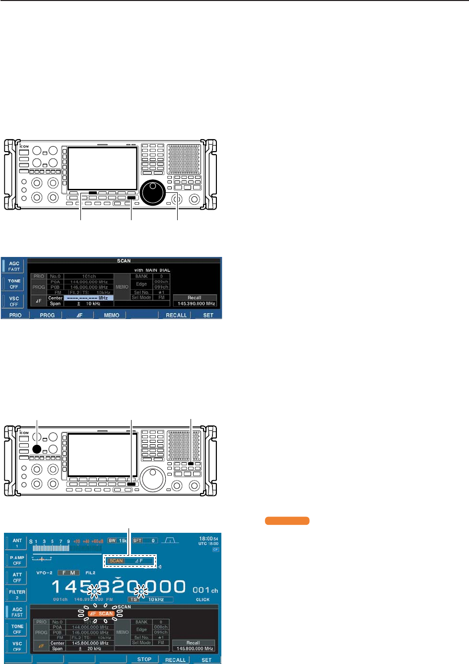
D∂F scan operation
qPush [EXIT/SET] several times to close a multifunc-
tion screen, if necessary.
wSelect the desired VFO or memory channel.
eSelect the desired operating mode.
• The operating mode can also be changed while scan-
ning.
rSet [SQUELCH] control open or closed.
• See page 9-2 for squelch condition.
tPush [∂F] to start the ∂F scan.
• Scan screen appears.
• “ ” and decimal points blink while scanning.
• When the center frequency is fixed and the operating
frequency exceeds the scanning range, ∂F scan jumps
to the fixed center frequency.
yWhen the scan detects a signal, the scan stops,
pauses or ignores it depending on the resume set-
ting and the squelch condition.
uTo cancel the scan, push [∂F].
• Pushing [F5•STOP] also cancels the scan.
• Pushing [EXIT/SET] closes the scan screen.
iPush and hold [F-6•RECALL] for 1 sec. to recall the
frequency that was set before starting the scan, if
desired.
:F SCAN
Scan indicator and ∂F scan indicator appear
[EXIT/SET][SQUELCH] [:F]
8-9
8
SCANS
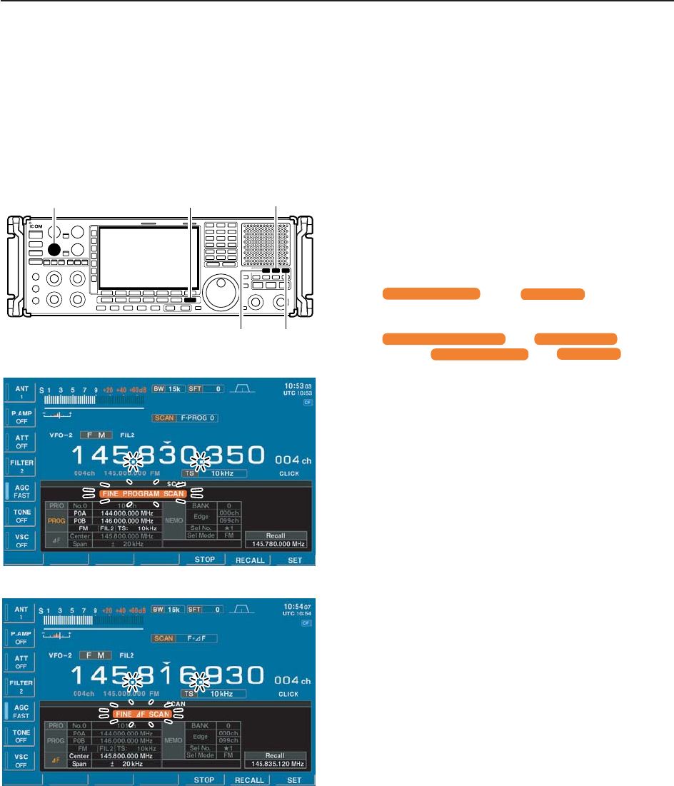
■Fine programmed scan/fine ∂F scan operation
In fine scan (programmed or ∂F), the scan speed de-
creases when the squelch opens, but the receiver
keeps scanning. The scanning tuning step shifts from
50 Hz to 10 Hz when the squelch opens.
qPush [EXIT/SET] several times to close a multifunc-
tion screen, if necessary.
wPush [F-5•SCAN] to select the scan screen.
eSet for programmed scan or ∂F scan as described
at p.8-6 and p.8-8.
rPush [PROG] or [∂F] to start a scan.
• “ ” or “ ” and decimal
points blink while scanning.
tPush [FINE] to start a fine scan.
• “ ” or “ ” blinks in-
stead of “ ” or “ ,” respec-
tively.
yWhen the scan detects a signal, the scan speed de-
creases but scan does not stop.
uPush [PROG] or [∂F] to stop the scan; push [FINE]
to cancel the fine scan.
• Pushing [F5•STOP] also cancels the scan.
• Pushing [EXIT/SET] closes the scan screen.
iPush and hold [F-6•RECALL] for 1 sec. to recall the
frequency that is set before starting the scan, if de-
sired.
:F SCAN
PROGRAM SCAN
FINE :F SCAN
FINE PROGRAM SCAN
:F SCAN
PROGRAM SCAN
[EXIT/SET][SQUELCH] [:F]
[PROG] [FINE]
8-10
8SCANS
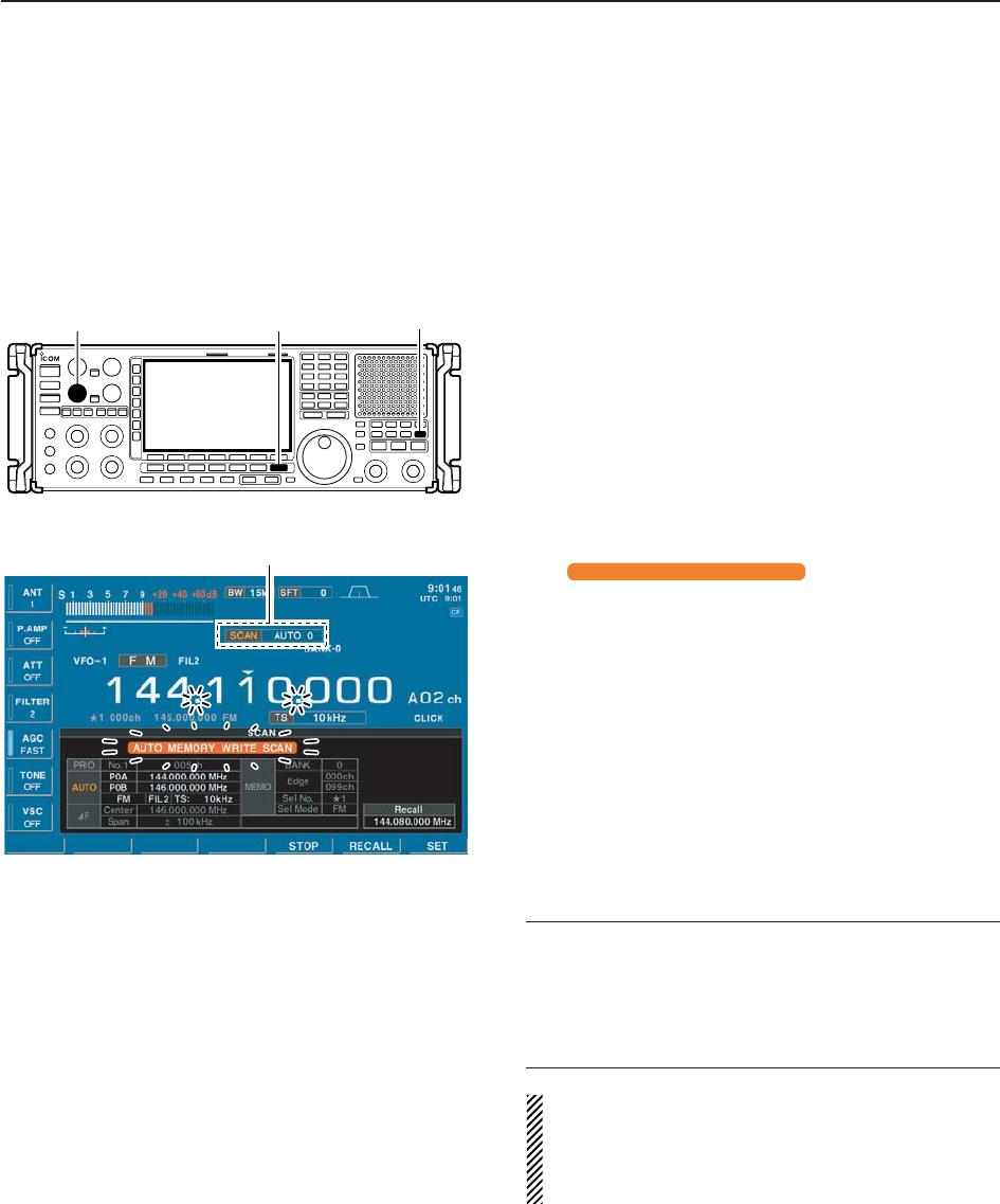
■Auto memory write scan operation
Auto memory write scan operates in the same way as
programmed scan. However, when a signal is re-
ceived, the received frequency is automatically written
into a memory channel in the auto write bank
(A00–A99).
qPush [EXIT/SET] several times to close a multifunc-
tion screen, if necessary.
wSelect the desired VFO or memory channel.
eSelect the desired operating mode.
• The operating mode can also be changed while scan-
ning.
rSet [SQUELCH] control open or closed.
• See page 8-3 for squelch condition.
tPush [AUTO] to start the auto memory write scan.
• Selected programmed scan start.
• Scan screen appears.
• “ ” and decimal points
blink while scanning.
• Push numeral key (0–9) to change to the other edges.
yWhen the scan detects a signal, the scan stops,
pauses or ignores it depending on the resume set-
ting and the squelch condition.
• The received frequency is automatically written into a
blank memory channel in the auto write bank.
uTo cancel the scan, push [AUTO].
• Pushing [F5•STOP] also cancels the scan.
• Pushing [EXIT/SET] closes the scan screen.
iPush and hold [F-6•RECALL] for 1 sec. to recall the
frequency that was set before starting the scan, if
desired.
✔
For your convenience
Ten auto memory write scans can be selected directly
from the keypad. Then the scan starts immediately.
➥Push numeral key (0–9) then push [AUTO] to start
the desired programmed scan.
The memory clear setting of the auto write bank can
be selected from the starting auto memory write
scan, by pushing and holding [AUTO], or manually.
See scan set mode (p. 8-4) for Auto MW SCAN
Memory Clear details.
AUTO MEMORY WRITE SCAN
Scan indicator and Auto memory write scan number appear
[EXIT/SET][SQUELCH] [AUTO]
8-11
8
SCANS
■Memory scan
All memory channels (except skip channels) in the se-
lected bank are scanned at up to 40 ch/sec.
DSetting
qPush [EXIT/SET] several times to close a multifunc-
tion screen, if necessary.
wPush [F-5•SCAN] to select scan setting screen.
ePush [F-4•MEMO] once to enter the bank selection.
rRotate the main dial to select the bank limit setting.
• Selected bank number or OFF (Bank OFF) appears.
tOr rotate [BANK] to select the other bank.
yPush [F-4•MEMO], then rotate main dial to select
the edge channel.
uPush [F-4•MEMO], then rotate main dial to select
the other edge channel.
iPush [F-4•MEMO], then rotate main dial to select
the desired select memory channel group for select
memory scan.
•‘★1’ to ‘★9’ and ‘ALL’ are available.
oPush [F-4•MEMO] to set the memory scan.
[F-4•MEMO] [EXIT/SET] Main dial [BANK]
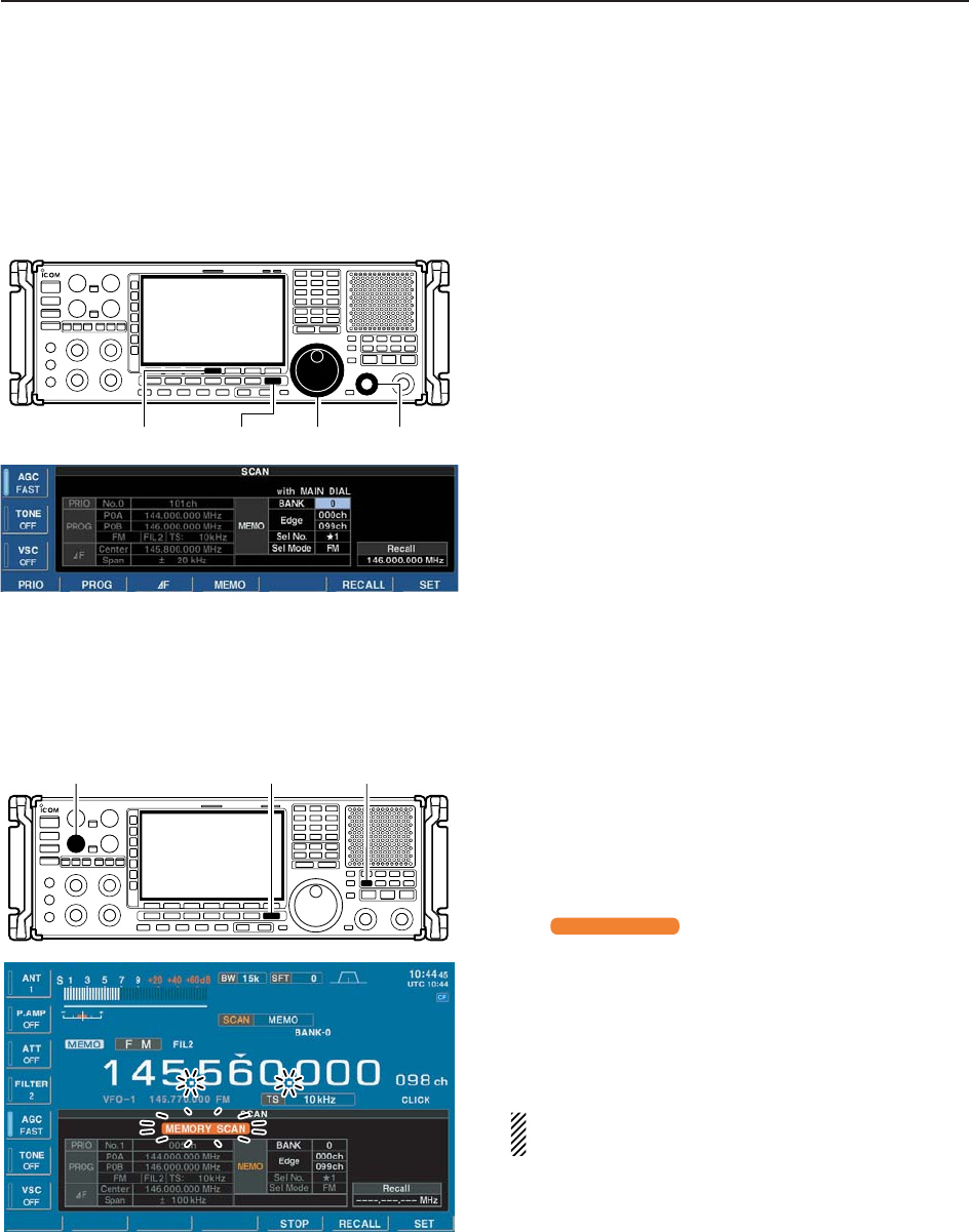
DMemory scan operation
qPush [EXIT/SET] several times to close a multifunc-
tion screen, if necessary.
wSet the [SQUELCH] control open or closed.
• See page 8-3 for squelch condition.
ePush [MEMO] to start the memory scan.
• Scan screen appears and memory mode is selected au-
tomatically.
• “ ” and decimal points blink during
memory scan.
rWhen the scan detects a signal, the scan stops,
pauses or ignores it depending on the resume set-
ting and the squelch condition.
tTo cancel the scan, push [MEMO].
• Pushing [F5•STOP] also cancels the scan.
• Pushing [EXIT/SET] closes the scan screen.
2 or more memory channels must be programmed
for memory scan to start.
MEMORY SCAN
[EXIT/SET] [MEMO][SQUELCH]
8-12
8SCANS
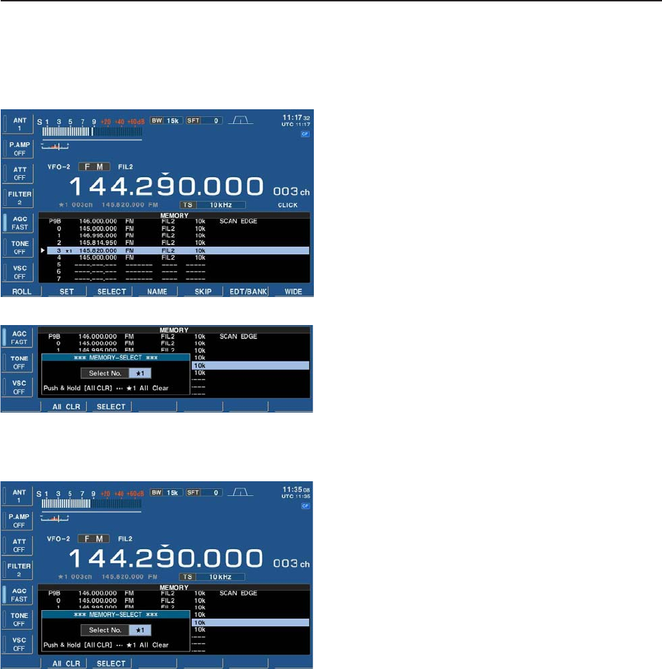
DProgramming the select memory scan setting
qPush [EXIT/SET] several times to close a multifunc-
tion screen, if necessary.
wPush [F-4•MEMORY] to select memory list screen.
eWhile pushing and holding [F-1•ROLL] or [F-2•SET],
rotate the main dial to select the desired memory
channel.
• [M-CH] (or [BANK]) control and direct keypad selection
can be used.
rPush and hold [F-3•SELECT] for 1 sec. to display
the memory-select window.
tRotate the main dial to select the desired select
memory channel group.
•★1 to ★9 are selectable.
• Memory-select window yPush [F-3•SELECT] to set the select setting ON.
• Push [F-3•SELECT] again to select the select setting
OFF.
uRepeat steps eto yto program another memory
channel as a select memory channel, if desired.
• If you want to set a same select channel group, skip
steps rand t.
iPush [EXIT/SET] to exit the memory list screen.
DErasing the select scan setting
qPush [EXIT/SET] several times to close a multifunc-
tion screen, if necessary.
wPush [F-4•MEMORY] to select memory list screen.
ePush and hold [F-3•SELECT] for 1 sec. to display
memory-select window.
rRotate the main dial to select the desired select
memory channel group to be erased.
tPush and hold [F-2• ALL CLR] for 1 sec. to clear all
select scan settings.
yPush [EXIT/SET] to exit the memory list screen.
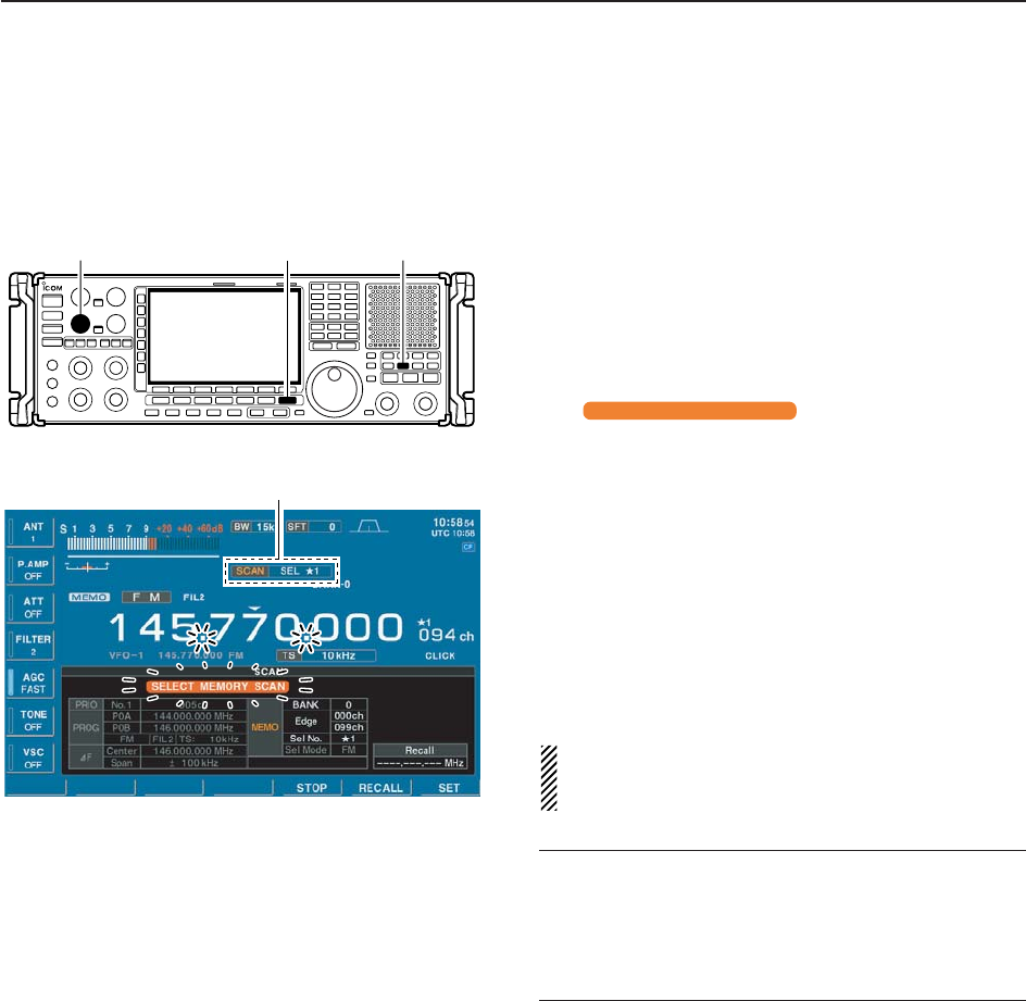
8-13
8
SCANS
DSelect memory scan operation
Select memory scan allows you to increase scan effi-
ciency by searching for specified channels group only.
qPush [EXIT/SET] several times to close a multifunc-
tion screen, if necessary.
wSet the [SQUELCH] control open or closed.
• See page 8-3 for squelch condition.
ePush [SEL] to start the select memory scan.
• Scan screen appears and memory mode is selected au-
tomatically.
• “ ” and decimal points blink
during select memory scan.
• Push numeral key (0–9) to change to the other groups.
rWhen the scan detects a signal, the scan stops,
pauses or ignores it depending on the resume set-
ting and the squelch condition.
tTo cancel the scan, push [MEMO].
• Pushing [F5•STOP] also cancels the scan.
• Pushing [EXIT/SET] closes the scan screen.
2 or more memory channels must be designated as
select memory channels, as well as the same select
scan number, for select memory scan to start.
✔
For your convenience
Ten select memory scans can be selected directly from
the keypad. Then the scan starts immediately.
➥Push numeral key (0–9) then push [SEL] to start the
desired select memory scan.
Scan indicator and select memory group number appear
SELECT MEMORY SCAN
[EXIT/SET] [SEL][SQUELCH]
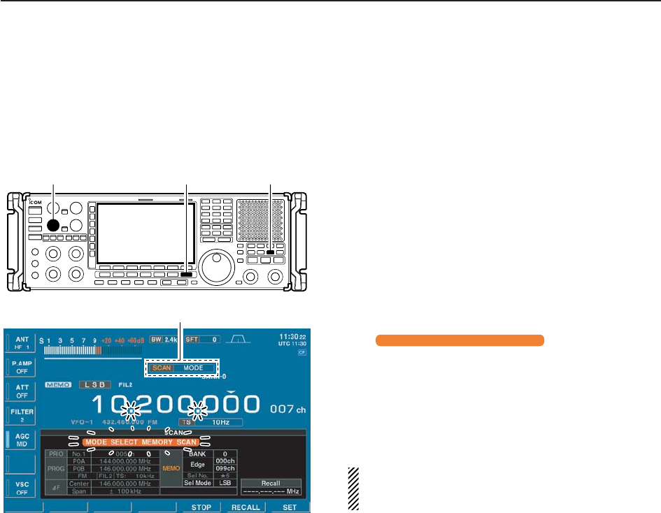
8-14
8SCANS
DMode select memory scan operation
To operate memory scan in a specific mode (ignoring
other modes), the mode select memory scan is avail-
able.
qPush [EXIT/SET] several times to close a multifunc-
tion screen, if necessary.
wSet the [SQUELCH] control open or closed.
• See page 8-3 for squelch condition.
eSelect the desired operating mode.
• The operating mode can also be changed while scan-
ning.
rPush [MODE] to start the mode select memory
scan.
• Scan screen appears and memory mode is selected au-
tomatically.
• “ ” and decimal points
blink during mode select memory scan.
tWhen the scan detects a signal, the scan stops,
pauses or ignores it depending on the resume set-
ting and the squelch condition.
yTo cancel the scan, push [MODE].
• Pushing [F5•STOP] also cancels the scan.
• Pushing [EXIT/SET] closes the scan screen.
2 or more memory channels with same operating
mode must be programmed for mode select mem-
ory scan to start.
MODE SELECT MEMORY SCAN
Scan indicator appears
[EXIT/SET] [MODE][SQUELCH]
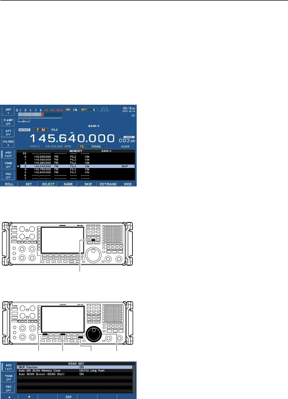
8-15
8
SCANS
■Skip scan
You can set the selected memory channel as a skip
channel which is skipped during memory scan. Its fre-
quency is also skipped during programmed and auto
memory write scans. This setting is useful to speed up
the scan speed.
DSpecifying skip channels
qPush [EXIT/SET] several times to close a multifunc-
tion screen, if necessary.
wPush [F-4•MEMORY] to select memory list screen.
eWhile pushing and holding [F-1•ROLL] or [F-2•SET],
rotate the main dial to select the memory channel to
be specified as a skip channel.
• [M-CH] (or [BANK]) control and direct keypad selection
can be used.
rPush [F-5•SKIP] to select the skip setting ON.
• “SKIP” indicator appears.
• Push [F-5•SKIP] again to select the skip setting OFF.
tRepeat steps eto rto program another memory
channel as a skip channel, if desired.
yPush [EXIT/SET] to exit the memory list screen.
DProgramming skip frequencies (for programming scan)
qStart programming scan as described on page 8-7.
wWhen the scan pauses on an undesired signal, push
and hold [MW] for 1 sec.
• The frequency is memorized into the skip bank as a skip
frequency.
DSkip scan setting
qPush [F-5•SCAN] to select scan screen.
wPush [F-7•SET] to select scan set mode.
ePush [F-1•Y] to select “SKIP Function.”
rRotate the main dial to select the desired condition.
• Push and hold [F-4•DEF] for 1 sec. to select the default
setting.
tPush [EXIT/SET] to return to scan menu.
[F-1•Y] [F-4•DEF] [EXIT/SET] Main dial
[MW]
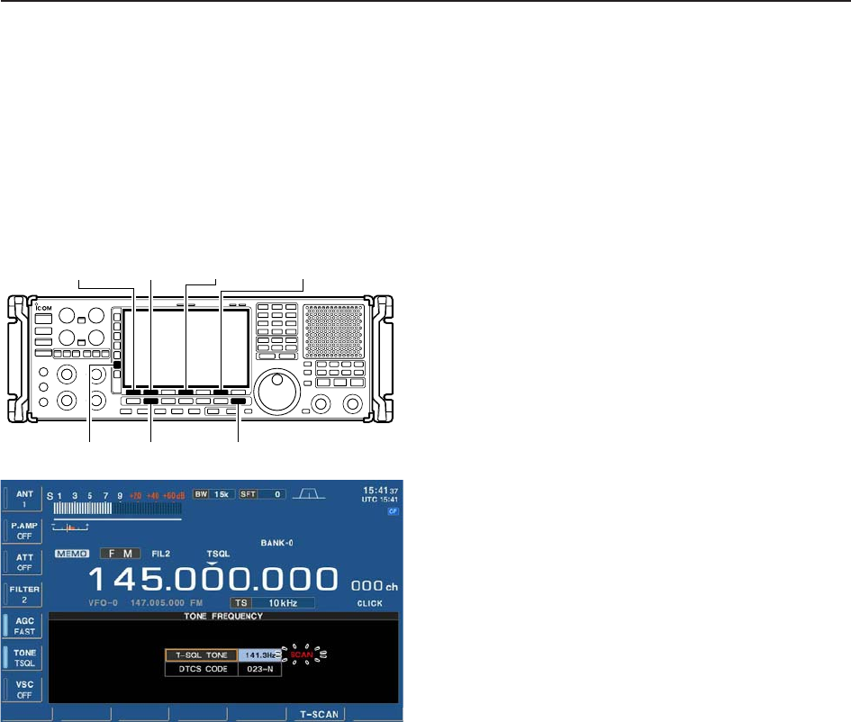
8-16
8SCANS
■Tone scan
The receiver can detect subaudible tones or the DTCS
code in a received signal. By monitoring a signal that is
being operated with tone or DTCS squelch function,
you can determine the tone frequency or DTCS code
necessary to open a squelch.
qSet the desired frequency or memory channel to be
checked for a tone frequency.
wPush [FM] to select FM mode.
ePush and hold [TONE] for 1 sec. to enter tone fre-
quency screen.
rPush [F-1•Y] or [F-2•Z] to check the tone squelch
frequency or DTCS code, respectively.
tPush [F-6•T-SCAN] to start the tone scan.
• “SCAN” blinks while scanning.
yWhen the tone frequency is detected, the tone scan
pauses.
• The tone frequency is set temporarily on a memory
channel. Program into the memory channel to store the
tone frequency permanently.
• The decoded tone frequency is used for the tone
squelch frequency or DTCS squelch code.
uTo stop the scan, push [F-6•T-SCAN].
• Push and hold [F-4•DEF] for 1 sec. to select the default
frequency.
iPush [EXIT/SET] to exit tone frequency screen.
[EXIT/SET][FM][TONE]
[F-1•Y] [F-2•Z] [F-6•T-SCAN][F-4•DEF]
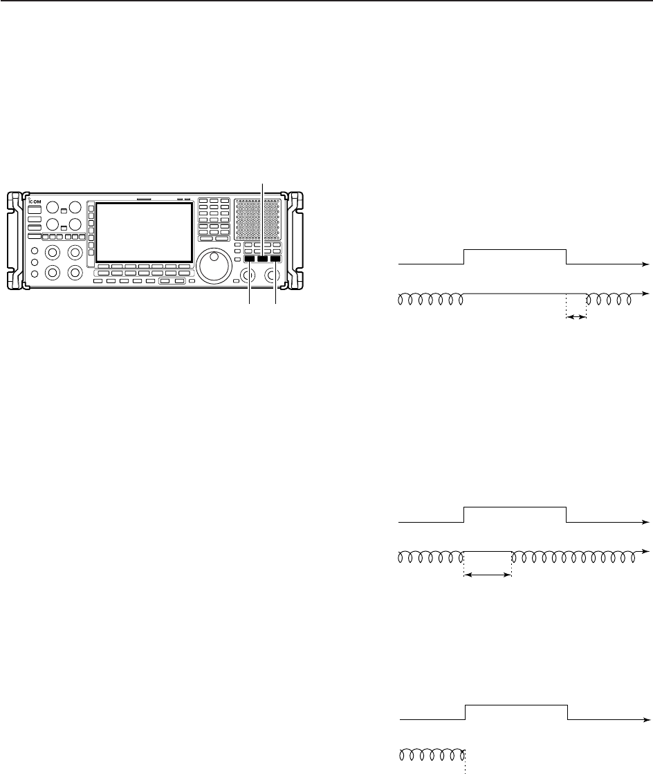
8-17
8
SCANS
■Scan resume condition
Scan pauses when finding a signal, and then resumes
or is cancelled depending on the selected scan resume
condition. There are 3 resume conditions.
• Scan resume OFF
Scan pauses until signal disappears, then resumes
after 2 sec.
➥Push [OFF] to set the scan pause timer to OFF.
• Scan resume indicator above this switch lights green.
• Scan resume ON with specified time period
Scan pauses for the adjusted delay period after re-
ceiving a signal, then resumes. When the received sig-
nal disappears, scan resumes after 2 to 20 sec.
➥Push [DELAY] to set the scan pause timer to speci-
fied time period according to [DELAY] control. (See
next page for setting scan delay.)
• Scan resume indicator above this switch lights green.
• Scan delay time can be set 2 to 20 sec.
• Scan cancel
Scan is cancelled when a signal is found during scan.
➥Push [] to set the scan pause timer to infinity (scan
cancel).
• Scan resume indicator above this switch lights green.
Signal no signal
scanning scan is cancelled
receiving a signal no signal
Scan
Signal no signal
scanning scanning
pausing
delay time
receiving a signal no signal
Scan
Signal no signal
scanning scanningpausing
2 sec.
receiving a signal no signal
Scan
[OFF] [
'
]
[DELAY]
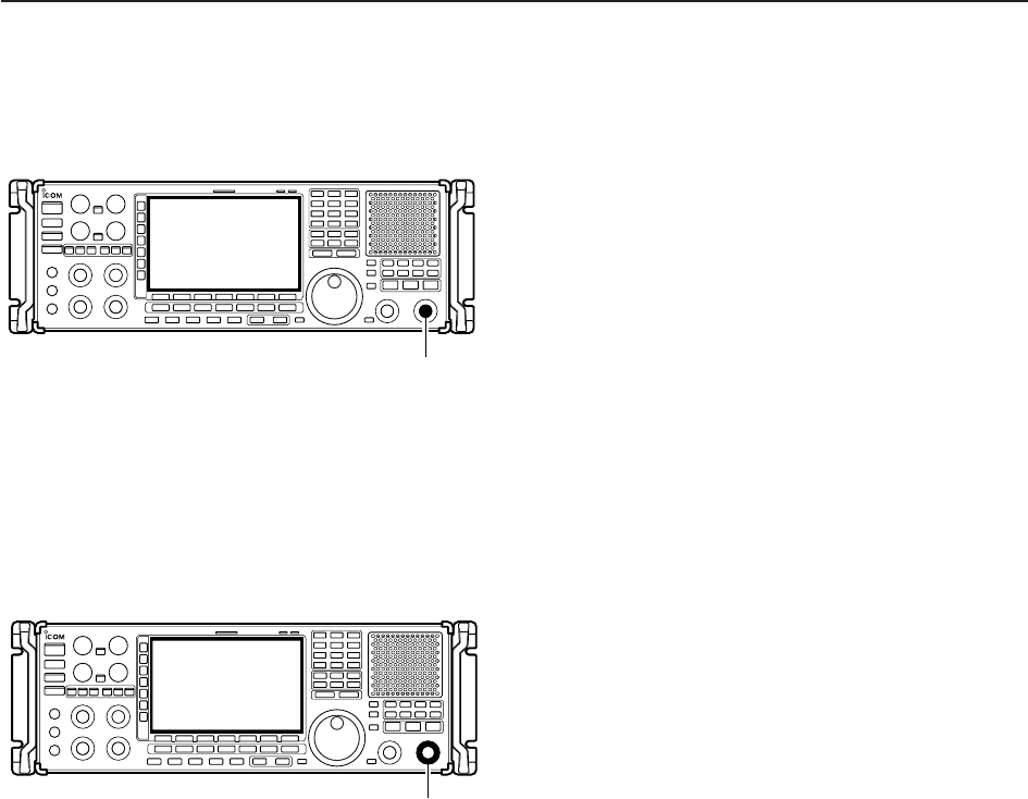
8-18
8SCANS
■Scan speed
➥Rotate [SPEED] to adjust the scan speed.
[SPEED]
■Scan delay
➥Rotate [DELAY] to adjust the scan pause time when
the scan resume setting is set to ‘DELAY.’
• Scan delay time can be set 2 to 20 sec.
[DELAY]

9-1
OTHER FUNCTIONS Section 9
■Voice synthesizer operation …………………………………………… 9-2
■Lock function …………………………………………………………… 9-2
DDial lock function ……………………………………………………… 9-2
DPanel lock function …………………………………………………… 9-2
■Dial click function ……………………………………………………… 9-3
■Antenna selection ……………………………………………………… 9-3
DAntenna type selection …………………………………………… 10-3
DTemporary memory ………………………………………………… 10-4
DAntenna selection mode …………………………………………… 10-4
■Antenna tuner operation ……………………………………………… 10-5
DTuner operation …………………………………………………… 10-5
DIf the tuner cannot tune the antenna …………………………… 10-6
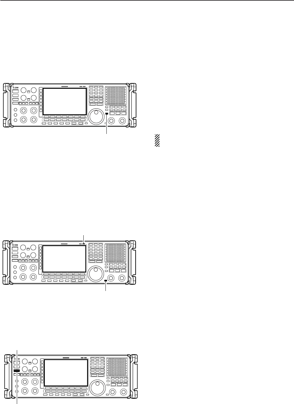
9-2
9OTHER FUNCTIONS
■Voice synthesizer operation
The IC-R9500 has a built-in voice synthesizer to an-
nounce the frequency, mode, etc. (S-meter level can
also be announced—p. 11-10) in clear, electronically-
generated voice, in English (or Japanese).
➥Push [SPCH] to announce the currently selected
frequency, etc.
• Push [SPCH] for 1 sec. to additionally announce the se-
lected mode.
➥Pushing a mode switch also announces the appro-
priate mode. (p. 11-11)
The output level of the voice synthesizer can be ad-
justed in level set mode. (p. 11-6)
■Lock function
The IC-R9500 has two kinds of lock functions: dial lock
and panel lock. The dial lock function locks only the
main dial, and panel lock function locks all front panel
operation.
DDial lock function
The dial lock function prevents frequency changes by
accidental movement of the tuning dial. The lock func-
tion electronically locks the dial.
➥Push [LOCK] to toggle the dial lock function ON or
OFF.
• The [LOCK] indicator lights orange when the dial lock
function is in use.
DPanel lock function
To prevent accidental frequency changes and unnec-
essary function access, use the panel lock function.
This function is also available with display sleep mode
➥Push [PANEL LOCK] to toggle the panel lock func-
tion ON or OFF.
• The [PANEL LOCK] indicator lights green when the
panel lock function is in use.
➥Push and hold [PANEL LOCK] for 1 sec. to turn the
panel lock with display sleep function ON.
• Pushing [PANEL LOCK] turns OFF the function.
• The [PANEL LOCK] indicator lights green and the dis-
play turns OFF when the sleep function is in use.
[PANEL LOCK] indicator
[PANEL LOCK]
[LOCK] indicator
[LOCK]
[SPCH]
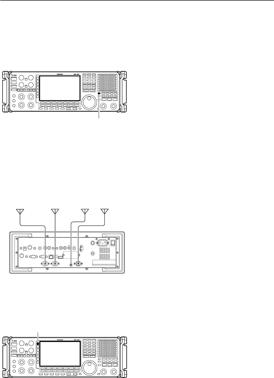
9-3
9
OTHER FUNCTIONS
■Dial click function
The IC-R9500 can turn the dial click function ON and
OFF. And the auto dial click setting is also available in
the others set mode (p. 11-12).
➥Push and hold [1/4] for 1 sec. to turn the dial click
function ON and OFF manually.
• “CLICK” appears.
[1/4]
■Antenna selection
The IC-R9500 has 3 antenna connectors for bands
below 30 MHz which are [HF ANT1], [HF ANT2] and
[ANT1/HF ANT3]. And antenna control voltage is also
output from [ANT SEL] connector for using external
preamplifier or antenna selector.
For each operating band the IC-R9500 covers, there
is a band memory which can memorize a selected an-
tenna. When you change the operating frequency be-
yond a band, the previously used antenna is automat-
ically selected (see left) for the new band. This function
allows automatic switching of 3 separate antennas for
HF bands operation.
After an antenna has been selected for use (by push-
ing [ANT]), the antenna is automatically selected
whenever that band is used.
[EXAMPLE]: a 3.5/7 MHz antenna is connected to
[HF ANT1], a 14/18 MHz antenna is connected to [HF
ANT2], a 24/28 MHz antenna is connected to [HF
ANT3]. After each antenna is selected, an antenna is
automatically selected when changing bands.
• Antenna selection
➥Push [ANT] to select the antenna from “ANT HF 1,”
“ANT HF 2” and “ANT HF 3.”
• The antenna indicator turns ON when other than default
antenna (ANT1) is selected.
➥Push and hold [ANT] for 1 sec to turn the antenna
control voltage ON and OFF from [ANT SEL] con-
nector.
• When it’s ON, “★” appears. Then the receiver output
13.8 V/100 mA max. from [ANT SEL] connector.
[ANT]
IC-R9500
1150~3335MHz
帯
30~1150MHz
帯
HF ANT1HF ANT2
HF ANT3

10-1
CLOCK AND TIMERS Section 10
■Time set mode ………………………………………………………… 10-2
■Daily timer setting …………………………………………………… 10-3
■Setting sleep timer …………………………………………………… 10-4
■Timer operation ………………………………………………………… 10-4
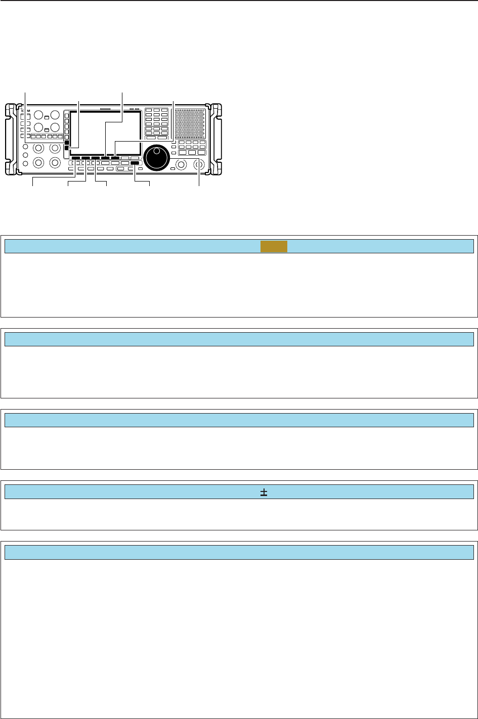
10-2
■Time set mode
The IC-R9500 has a built-in calendar and 24-hour
clock with daily power ON/OFF timer functions. Before
operating these timer functions, set the current date
and time.
qPush [EXIT/SET] to close multifunction screen, if
necessary.
wPush [F-7•SET] to select set mode menu screen.
ePush [F-4•TIME] to select time set mode.
rPush [F-1•Y] or [F-2•Z] to select the desired item.
tRotate the main dial to set or select the desired
value or condition.
yPush [EXIT/SET] to exit time set mode.
[F-1•Ω] [F-2•≈]Main dial[EXIT/SET]
[F-4•DEL][F-5•EDIT]/[F-5•SET]
[ABC]/[abc][123]/[Symbol]
[F-3•Ω≈]
10 CLOCK AND TIMERS
Sets the date. zPush [F-3•Ω≈] to select between the year and the
month/day, then rotate the main dial to select them.
• The date setting and “DATE-set Push [SET]” indication
blink.
xPush [F-5•SET] to set the date.
Date
2000
–
1
–
1 ( Sat )
Sets the local time. zRotate the main dial to set the local time.
• The time setting and “TIME-set Push [SET]” indication
blink.
xPush [F-5•SET] to set the time.
Time (Now)
1:23
Turns the clock 2 display ON and OFF.
The clock 2 is convenient to indicate UTC or another
country’s local time, etc.
• ON : Clock 2 is displayed below the local time dis-
play.
• OFF : The clock 2 is not displayed.
CLOCK2 Function
ON
Sets the desired offset time period for clock 2 within
–24:00 to +24:00 in 5 min. steps.
• Push and hold [F-4•DEF] for 1 sec. to select the default
value.
CLOCK2 Offset
0:00
Sets the desired 3-character name for clock 2.
Capital letters, small letters, numerals, some symbols
(! # $ % & ¥ ? " ’ ` ^ + – ✱/ . , : ; = < > ( ) [ ] { } | _ ~@)
and spaces can be used.
zPush [F-5•EDIT] to select the name edit condition.
• The cursor under the 1st character blinks.
xPush [ABC], [abc], [123] or [Symbol] to select the
character group, then rotate the main dial to select
the character.
• Push [ABC] or [abc] to toggle capital and small letters.
• Push [123] or [Symbol] to toggle numerals and sym-
bols.
• Push [F-1•Ω] or [F-2•≈] for cursor movement.
• Push [F-3•DEL] to delete the selected character.
• Push [F-4•SPACE] to input a space.
• Using the receiver’s keypad, [0]–[9], can also enter nu-
merals.
cPush [EXIT/SET] to set the name.
CLOCK2 Name
UTC
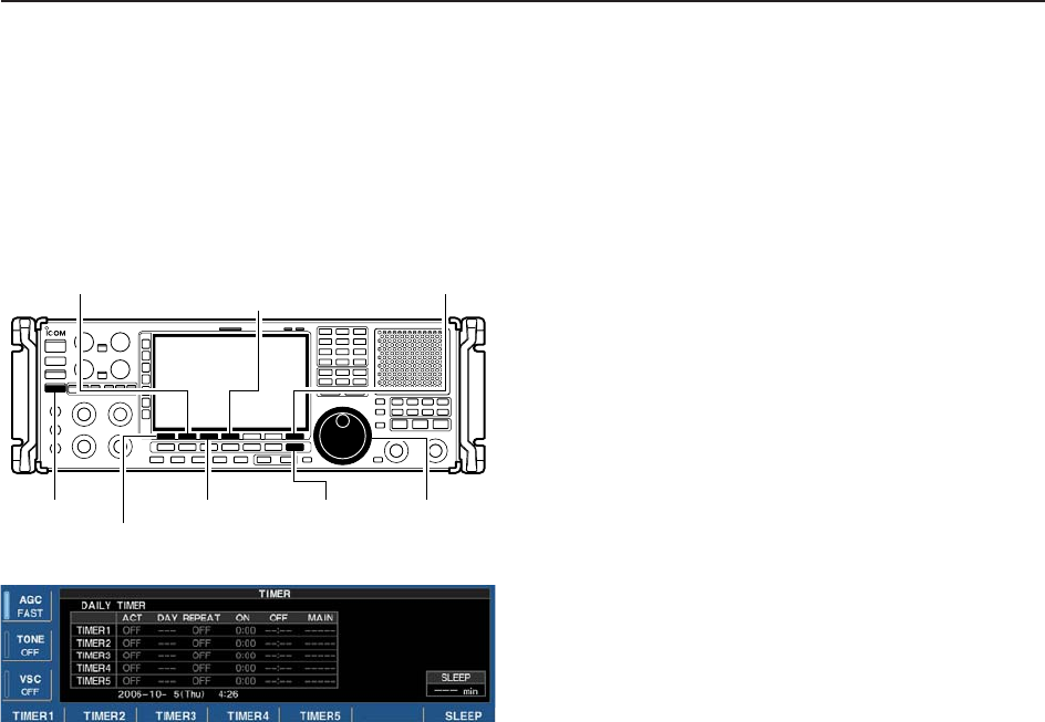
10-3
■Daily timer setting
The receiver turns power ON and/or OFF automatically
at the specified day and time, with the specified fre-
quency settings.
qPush [EXIT/SET] several times to close multifunc-
tion screen, if necessary.
wPush [TIMER] for 1 sec. to select timer set screen.
ePush one of [F-1•TIMER1] to [F-5•TIMER5] to se-
lect the desired timer.
rRotate the main dial to select the timer action ON
and OFF.
tPush [F-2•≈] to select the “DAY” cell, then rotate the
main dial to select the desired day of the week.
• Select “– – –” not to specify daily operation and activate
the timer every day.
• Once a day of the week is selected, push [F-4•CLR] for
1 sec. to select “– – –.”
yPush [F-2•≈] to select the “REPEAT” cell, then ro-
tate the main dial to select the repeat function ON
or OFF.
• ON : The timer functions every selected day of the
week. (repeats)
• OFF : The timer does not repeat.
uPush [F-2•≈] to select the “ON” cell, then rotate the
main dial to set the desired receiver power ON time.
• When using power OFF timer only, push [F-4•CLR] for
1 sec. to select “– – –.”
iPush [F-2•≈] to select the “OFF” cell, then rotate the
main dial to set the desired receiver power OFF
time.
• When using power ON timer only, push [F-4•CLR] for
1 sec. to select “– – –.”
oPush [F-2•≈] to select the “MAIN” cell, then rotate
the main dial to select the desired memory channel
number in the main readout.
• If using the currently set VFO condition in main readout,
push [F-4•CLR] for 1 sec. to select “– – –.”
!0 Push [F-7•SET] to set the timer.
• The timer indicator above [TIMER] switch lights green.
!1 Repeat steps eto !0 to set other timers, if desired.
!2 Push [EXIT/SET] to exit timer set screen.
[EXIT/SET]
[F-4•TIMER4]/[F-4•CLR]
[F-3•TIMER3]
[TIMER]
[F-7•SET]
[F-1•TIMER1]/[F-1•Ω]
[F-2•TIMER2]/[F-2•≈]
Main dial
10
CLOCK AND TIMERS
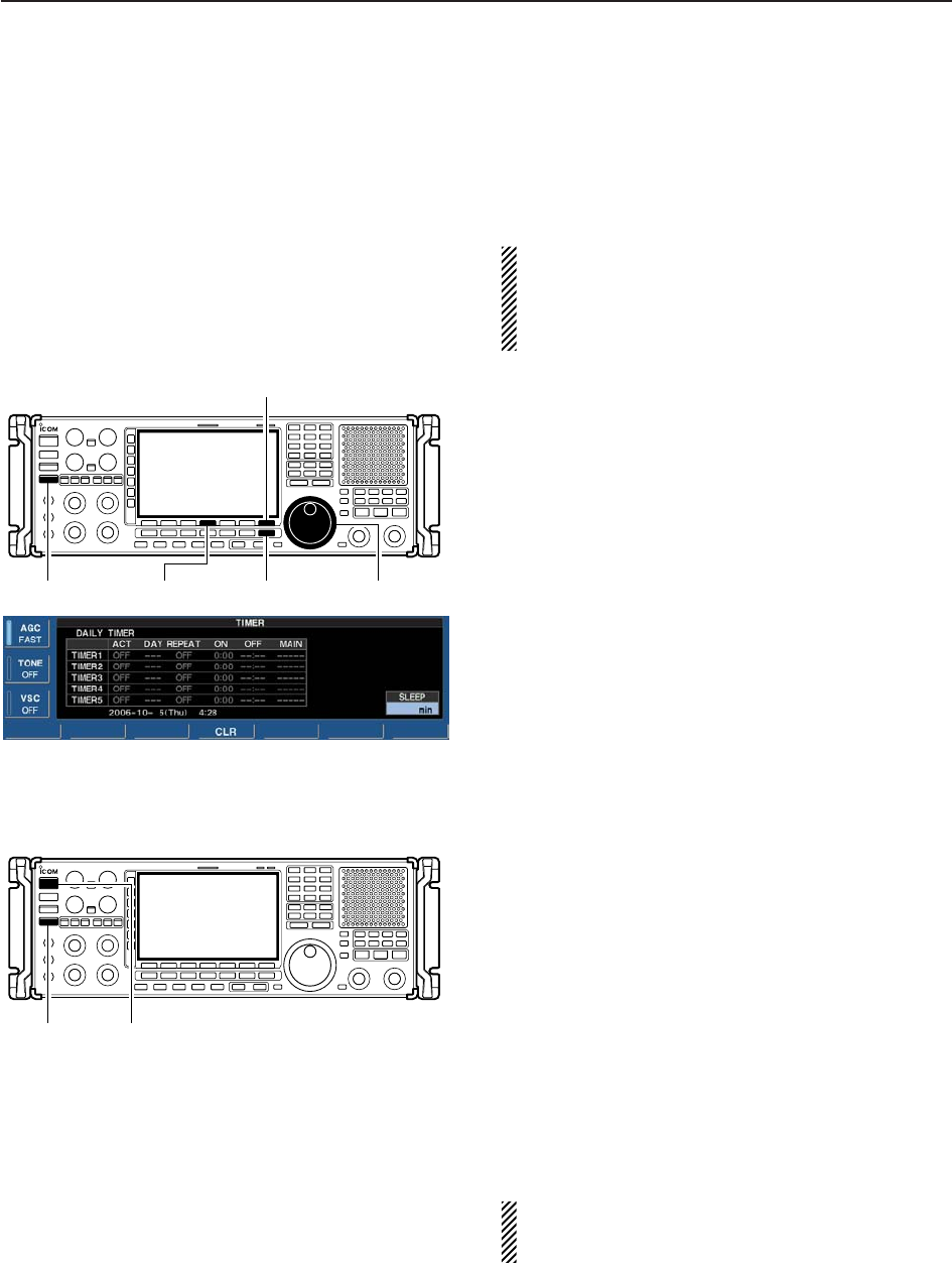
10-4
■Setting sleep timer
The sleep timer turns the receiver power OFF auto-
matically after a set period. The timer can be set to
5–120 min. in 5 min. steps.
The sleep timer function counts the ‘minute’ unit,
and does not count the ‘second’ unit. For example,
when the sleep timer is started at 12:00 59, first one
minute past for just 1 sec. That is way it has max.
59 sec. an error. This is normal, not a malfunction.
qPush [EXIT/SET] several times to close a multifunc-
tion screen, if necessary.
wPush [TIMER] for 1 sec. to select timer set screen.
ePush [F-7•SLEEP] to select the sleep timer set con-
dition.
• “– – –” blinks.
rSet the desired time period using the main dial.
• “TIMER–set Push [SET]” blinks.
• Push [F-4•CLR] to select “– – –” to cancel the setting.
tPush [F-7•SET] to set the time.
• Push [EXIT/SET] to cancel the setting.
• The timer indicator above [TIMER] switch lights green.
yPush [EXIT/SET] to exit timer set screen.
uThe receiver emits 10 beeps and turns OFF after
the sleep timer period elapses.
• The timer indicator blinks while beeping.
• Push [TIMER] momentarily to cancel the sleep timer, if
desired.
■Timer operation
qPreset the daily timer as described previously.
wPush [TIMER] momentarily to turn the timer function
ON.
• The timer indicator above this switch lights green when
the timer function is ON.
ePush and hold [POWER] for 1 sec. to turn the power
OFF.
• The timer indicator lights continuously.
rWhen the set time arrives, the power is automati-
cally turned ON.
tThe receiver emits 10 beeps and turns OFF after
the power-off period elapses.
• The timer indicator blinks while beeping.
• Push [TIMER] momentarily to cancel the sleep timer, if
desired.
The timer action in timer set screen must be turned
ON to enable the timer operation, described above
“Setting sleep timer” steps r.
[TIMER] [POWER]
[EXIT/SET][TIMER] Main dial[F-4•CLR]
[F-7•SLEEP]/[F-7•SET]
10 CLOCK AND TIMERS