ICOM orporated 284400 Scanning Receiver User Manual IC R9500 manual
ICOM Incorporated Scanning Receiver IC R9500 manual
Contents
- 1. Users Manual 1
- 2. Users Manual 2
- 3. Users Manual 3
Users Manual 3

11-1
SET MODE Section 11
■Set mode description ………………………………………………… 11-2
DSet mode operation ………………………………………………… 11-2
DScreen arrangement ……………………………………………… 11-3
■Level set mode ………………………………………………………… 11-4
■ACC set mode ………………………………………………………… 11-7
■Display set mode ……………………………………………………… 11-8
■Others set mode ……………………………………………………… 11-10
■CF card/USB-Memory set menu …………………………………… 11-16
DCF/USB-Memory set screen arrangement …………………… 11-16
DLoad option set mode …………………………………………… 11-17
■File saving …………………………………………………………… 11-18
■File loading …………………………………………………………… 11-19
■Changing the file name ……………………………………………… 11-20
■File copying …………………………………………………………… 11-21
■Deleting a file ………………………………………………………… 11-22
■Unmount an USB-Memory ………………………………………… 11-22
■Formatting the CF card or USB-Memory ………………………… 11-23
■Display set (Video) mode …………………………………………… 11-24
■LCD set mode ………………………………………………………… 11-26
11-2
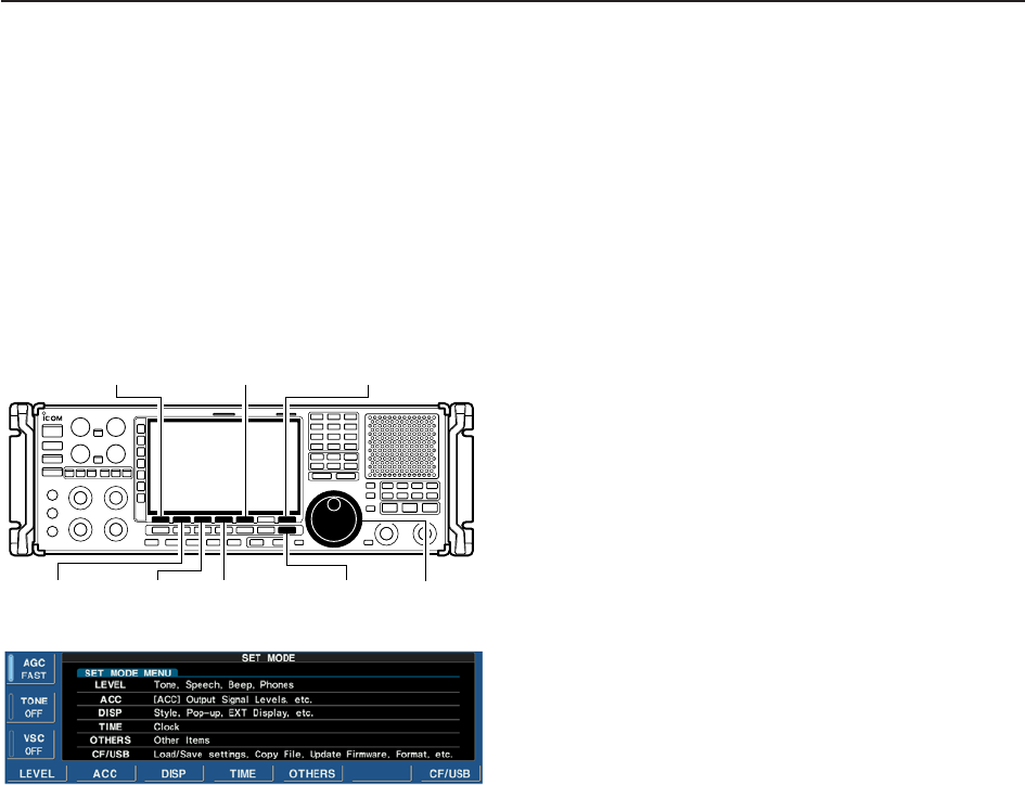
■Set mode description
Set mode is used for programming infrequently
changed values or conditions of functions. The IC-
R9500 has a level set mode, display set mode, timer
set mode, accessory set mode, others set mode and
CF/USB-Memory set mode.
DSet mode operation
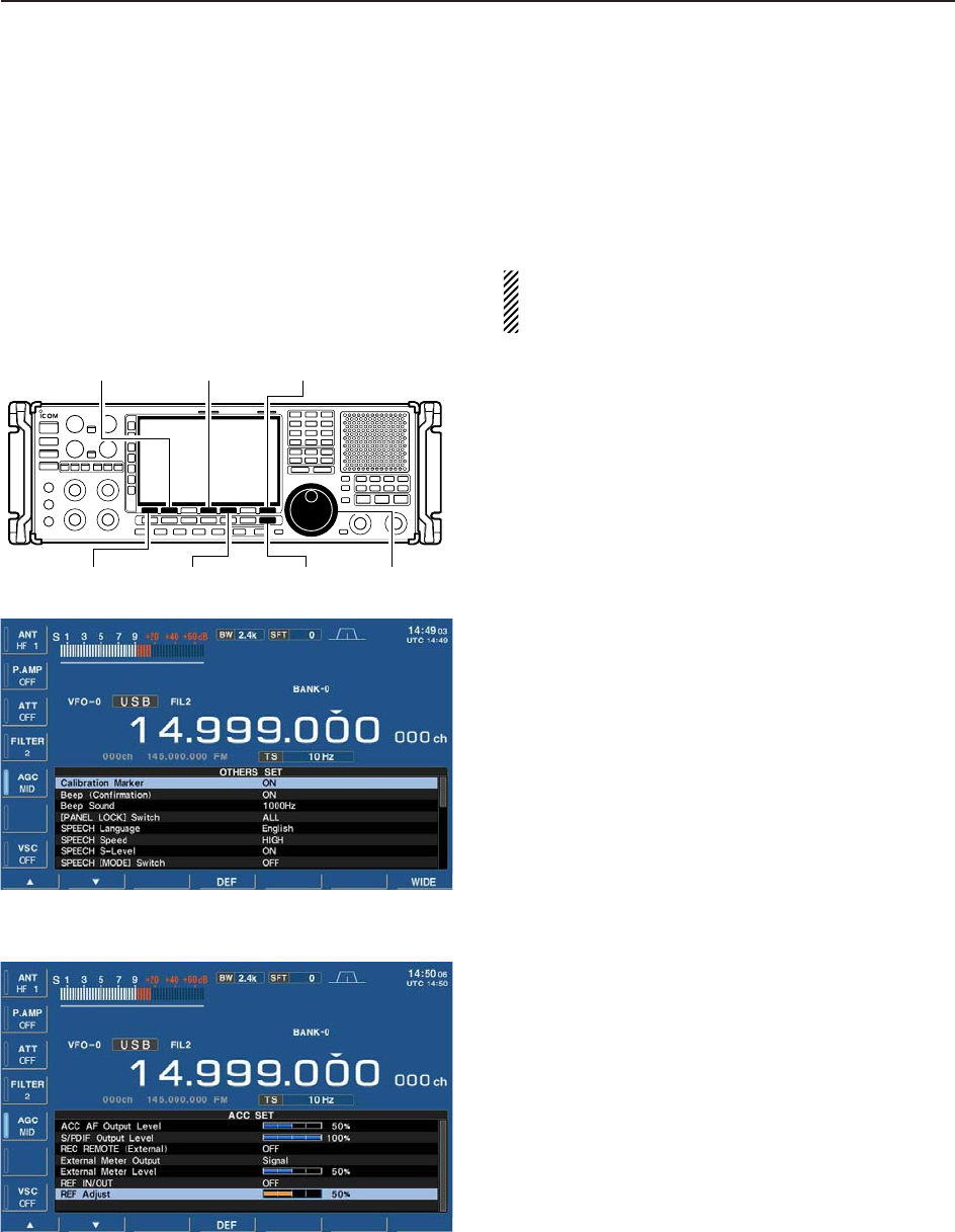
qPush [EXIT/SET] several times to close a multi-
function screen, if necessary.
wPush [F-7•SET] to select set mode menu screen.
• Pushing and holding [EXIT/SET] for 1 sec. also selects
set mode menu screen.
ePush [F-1•LEVEL], [F-2•ACC], [F-3•DISP],
[F-4•TIME], [F-5•OTHERS] or [F-7•CF/USB] to
enter the desired set mode.
rFor level, accessory, display and others set mode,
push [F-7•WIDE] to toggle wide and normal screen.
tPush [F-1•Y] or [F-2•Z] to select the desired item,
then rotate main dial to adjust/select the desired
value or condition.
• Pushing [F-3•Ω≈] operation may be necessary for
some items.
yPush [EXIT/SET] twice to exit set mode.
[EXIT/SET] Main dial
[F-1•LEVEL]
[F-2•ACC] [F-3•DISP]
[F-5•OTHERS]
[F-4•TIME]
[F-7•CF/USB]
11 SET MODE
11-3
11
SET MODE
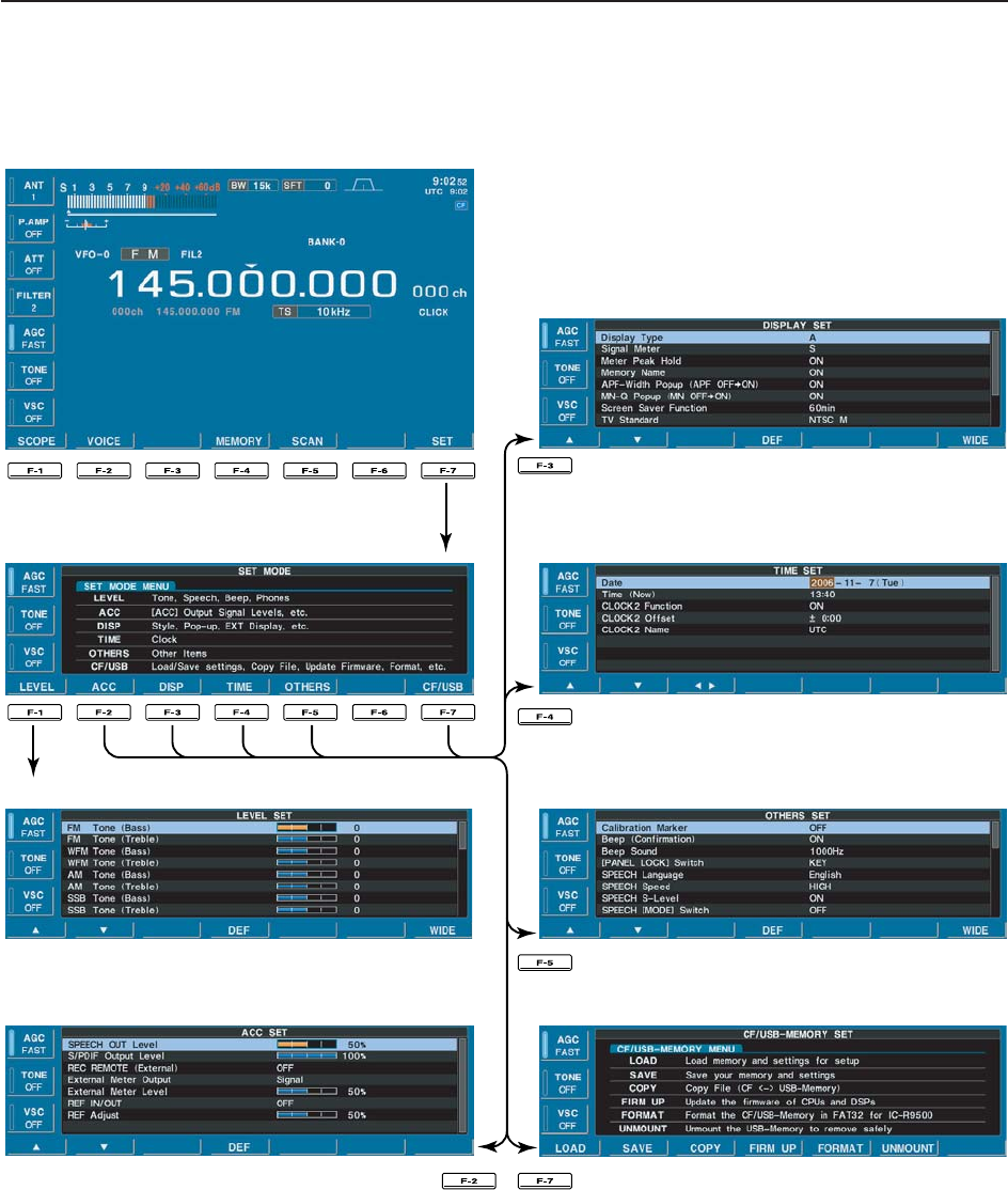
DScreen arrangement
• Set mode menu screen (p. 11-2)
• Level set mode (p. 11-4)
• ACC set mode (p. 11-7)
• Time set mode (p. 10-2)
• Display set mode (p. 11-8)
• Miscellaneous (Others) set mode (p. 11-10)
• CF/USB-Memory set menu (p. 11-16)
11-4
11 SET MODE
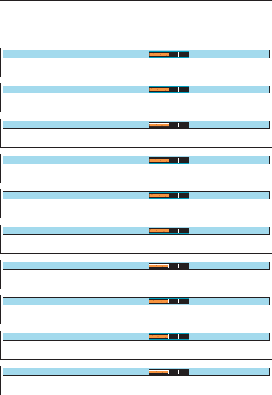
■Level set mode
Sets the bass level of the receive audio in FM mode
from –5 to +5. (default: 0)
FM Tone (Bass)
0
Sets the treble level of the receive audio in FM mode
from –5 to +5. (default: 0)
FM Tone (Treble)
0
Sets the bass level of the receive audio in WFM mode
from –5 to +5. (default: 0)
WFM Tone (Bass)
0
Sets the treble level of the receive audio in WFM
mode from –5 to +5. (default: 0)
WFM Tone (Treble)
0
Sets the bass level of the receive audio in AM mode
from –5 to +5. (default: 0)
AM Tone (Bass)
0
Sets the treble level of the receive audio in AM mode
from –5 to +5. (default: 0)
AM Tone (Treble)
0
Sets the bass level of the receive audio in SSB mode
from –5 to +5. (default: 0)
SSB Tone (Bass)
0
Sets the treble level of the receive audio in SSB mode
from –5 to +5. (default: 0)
SSB Tone (Treble)
0
Sets the bass level of the receive audio in CW mode
from –5 to +5. (default: 0)
CW Tone (Bass)
0
Sets the treble level of the receive audio in CW mode
from –5 to +5. (default: 0)
CW Tone (Treble)
0
11-5
11
SET MODE
■Level set mode (continued)
Sets the bass level of the receive audio in FSK mode
from –5 to +5. (default: 0)
FSK Tone (Bass)
0
Sets the treble level of the receive audio in FSK mode
from –5 to +5. (default: 0)
FSK Tone (Treble)
0
Sets the de-emphasis circuit ON and OFF when the
15 kHz width filter is used in FM mode. (default: ON)
(FM 15k)
ON
Sets the de-emphasis circuit ON and OFF when the
7 kHz width filter is used in FM mode. (default: ON)
(FM 7k)
ON
Sets the AF high cut filter circuit ON and OFF when
the 50 kHz width filter is used in FM mode. (default:
OFF)
AF High Cut (FM 50k)
OFF
Sets the AF high cut filter circuit ON and OFF when
the 15 kHz width filter is used in FM mode. (default:
ON)
(FM 15k)
ON
Sets the AF high cut filter circuit ON and OFF when
the 7 kHz width filter is used in FM mode. (default:
ON)
(FM 7k)
ON
Sets the AF high cut filter circuit ON and OFF in WFM
mode. (default: OFF)
(WFM)
OFF
De-emphasis is the use of an amplitude-frequency
characteristic complimentary to the one used for pre-
emphasis prior to transmission.
Sets the de-emphasis circuit ON and OFF when the
50 kHz width filter is used in FM mode. (default: OFF)
De-Emphasis (FM 50k)
OFF
11-6
11 SET MODE
Turns the AF high cut filter circuit ON and OFF in SSB
mode. (default: ON)
(SSB)
ON
Turns the AF high cut filter circuit ON and OFF in CW
mode. (default: ON)
(CW)
ON
Turns the AF high cut filter circuit ON and OFF in FSK
mode. (default: ON)
(FSK)
ON
Turns the AF high cut filter circuit ON and OFF in P25
mode. (default: ON)
(P25)
ON
■Level set mode (continued)
Sets the voice synthesizer audio output level from 0 to
100% in 1% steps. (default: 50%)
Speech Level
50%
Sets the key-touch beep output level from 0 to 100%
in 1% steps. (default: 50%)
Beep Level
50%
Turns the key-touch beep output level limiting capa-
bility from ON and OFF. (default: ON)
Beep Level Limit
ON
Sets the ratio for audio output level from the head-
phone to the internal speaker from 0.60 to 1.40 range
in 0.01 steps. (default: 1.00)
Phones Level Ratio
1.00
Turns the AF high cut filter circuit ON and OFF in AM
mode. (default: OFF)
(AM)
OFF
11-7
11
SET MODE
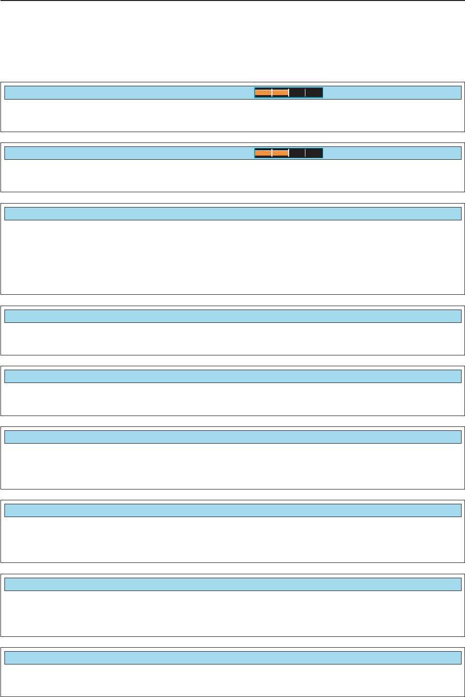
■ACC set mode
Sets the speech audio output level from [SPEECH
OUT] from 0 to 100% in 1% steps.
• Outputs approx. 200 mV at 50% (default) setting.
SPEECH OUT Level
50%
Sets the desired output level of [S/P DIF OUT], from 0
to 100% in 1% steps. (default: 100%)
S/PDIF Output Level
100%
Sets the output level for an external meter indication
from 0 to 100% range in 1% steps.
• Approx. 2.5 V at 50% (default) setting for full-scale indica-
tion. (4.7 kimpedance)
External Meter Level
50%
External Meter Level
50%
Selects the receiver’s reference signal condition from
IN, OFF and OUT. • IN : Use an external reference signal for the IC-
R9500.
• OFF : No input or output of the reference signal.
(default)
• OUT : Outputs the IC-R9500 reference signal to
externally connected equipment(s) for their
reference.
NOTE: If the applied reference signal is off-fre-
quency, or no signal is applied with “IN” selection,
the IC-R9500 will not work properly. Select “OFF”
or “OUT” then reboot the IC-R9500.
External Meter Level
50%
Reference IN/OUT
OFF
Adjusts the internal reference frequency within 0 to
100% in 1% steps during frequency calibration. NOTE: Default setting is different for each receiver.
REF Adjust
40%
Turns the control signal of external equipment output
capability ON and OFF. (default: OFF) • OFF : No signal output from [REC REMOTE]
jacks. (default)
• ON : The [REC REMOTE] jacks shorts to
ground when receiving a signal or the
squelch is open.
REC Remote (External)
OFF
Selects the squelch condition output for an external
meter indication from pin 8 of [ACC]. • Signal : Outputs the receiving signal strength
level during receiving. (default)
• Signal+SQL: Outputs the receiving signal strength
level during receiving and outputs
squelch open/close condition.
External Meter Output
Signal

Selects the desired display type from A and B.
(default: A)
Display Type
A
■Display set mode
Selects the desired signal meter type from “S,” “dBµ,”
“dBµ[EMF]” and “dBm.”
(default: S)
Signal Meter
S
Turns the meter peak hold function ON or OFF.
(default: ON)
This function is used for the bar meter only.
Meter Peak Hold
ON
Sets the memory name indication, during memory
mode operation, ON and OFF. (default: ON) • ON : The programmed memory name is displayed
above the frequency indication.
• OFF : No memory name is displayed even a mem-
ory name is programmed.
Memory Name
ON
11-8
11 SET MODE
Selects the pop-up indication of the APF filter width
ON and OFF when the APF function is turned ON.
(default: ON)
APF-Width Popup (APF OFF➞ON)
ON
Selects the pop-up indication of the received ID in
P25 mode ON and OFF. (default: ON) • ON (Hex): The received ID code (hexadecimal indi-
cation) is displayed when an ID code is
received.
• ON (Dec): The received ID code (decimal indication)
is displayed when an ID code is received.
(default)
• OFF : No ID code is displayed when an ID code
is displayed.
P25 RX ID Popup
ON (Dec)
Selects the pop-up indication of the notch filter width
ON and OFF when the notch filter is turned ON.
(default: ON)
MN-Q Popup (MN OFF➞ON)
ON
Turns the screen saver function ON (15, 30 or 60 min-
utes) and OFF. (default: 60 min.) The screen saver will activate when no operation is
performed for the selected time period to protect the
LCD from “burn-in.”
Screen Saver Function
60min
NOTE: “Display set (Video) mode” is described on page 11-24.

11-9
11
SET MODE
Sets the introductory text, up to 10-character long,
displayed in the opening screen.
Capital letters, small letters, numerals, some symbols
(– / . @) and spaces can be used.
zPush [F-5•EDIT] to select the name edit condition.
• The cursor under the 1st character blinks.
xPush [ABC], [abc], [123] or [Symbol] to select the
character group, then rotate the main dial to select
the character.
• Push [ABC] or [abc] to toggle capital and small letters.
• Push [123] or [Symbol] to toggle numerals and sym-
bols.
• Push [F-1•Ω] or [F-2•≈] for cursor movement.
• Push [F-3•DEL] to delete the selected character.
• Push [F-4•SPACE] to input a space.
• Using the receiver’s keypad, [0]–[9], can also enter nu-
merals.
cPush [EXIT/SET] to set the name.
Opening Comment
Select “ON” when the external display is connected.
(default: OFF)
• At least 800×600 pixel resolution is required for the dis-
play.
External Display
OFF
Selects the suitable pulse level for the connected ex-
ternal display from H and L. (default: H)
External Display Sync Pulse
H
Turns the opening message screen indication capa-
bility ON and OFF. (default: ON)
Opening Message
ON
■Display set mode (continued)

11-10
11 SET MODE
■Others set mode
This item is used for a simple frequency check of the
receiver. (default: OFF)
See p. 12-5 for calibration procedure.
NOTE: Turn the calibration marker OFF after
checking the frequency of the receiver.
Calibration Marker
OFF
A beep sounds each time a switch is pushed to con-
firm it. This function can be turned OFF for silent op-
eration. (default: ON)
The beep output level can be set in level set mode.
(p. 11-6)
Beep (Confirmation)
ON
Sets the desired key-touch beep sound frequency
from 500 to 2000 Hz in 10 Hz steps. (default:
1000 Hz)
Beep Sound
1000Hz
Selects the Panel lock function activity from “ALL” and
“KEY.” (default: ALL)
[PANEL LOCK] SWITCH
ALL
Selects the speech language from English and Japan-
ese. (default: English)
SPEECH Language
English
Selects the speech speed from HIGH (faster) and
LOW (slower). (default: HIGH)
SPEECH Speed
High
The IC-R9500 speech processor has frequency,
mode and signal level announcement. Signal level an-
nouncement can be deactivated if desired.
(default: ON)
When “OFF” is selected, the signal level is not an-
nounced.
SPEECH S-Level
ON
11-11
11
SET MODE
Selects the frequency speech capability when scan
stops; ON or OFF.
NOTE: Output jacks are selected depending on
“SPEECH Mix” settings. See the combination of
“REC SPEECH” and “SPEECH Mix” settings in the
table below.
• ON : The frequency is announced through the
[REC OUT]/[LINE OUT] or [SPEECH OUT]
when scan stops.
• OFF : No speech audio outputs when scan stops.
REC SPEECH
OFF
Selects the speech audio output from the [REC OUT]
or [LINE OUT].
NOTE: See the combination of “REC SPEECH”
and “SPEECH Mix” settings below table.
• All : Outputs the speech audio when speech
operation is performed from the front
panel or depends on above “REC
SPEECH” setting. (default)
• Operation: Outputs the speech audio when speech
operation is performed from the front
panel.
• OFF : No speech audio outputs from [REC
OUT] or [LINE OUT].
SPEECH Mix
All
Selects the operating mode speech capability when a
mode switch is pushed; ON or OFF.
(default: OFF)
When “ON” is selected, the selected operating mode
is announced when a mode switch is pushed.
SPEECH [MODE] SWITCH
OFF
■Others set mode (continued)
Switch setting Speech operation from front panel Scan stops
REC
SPEECH
OFF
ON
SPEECH
Mix
All
Operation
OFF
All
Operation
OFF
Internal
Speaker
✔
✔
–
✔
✔
–
[REC OUT] /
[LINE OUT]
✔
✔
–
✔
✔
–
[SPEECH OUT]
✔
✔
✔
✔
✔
✔
Internal
Speaker
–
–
–
✔
✔
–
[REC OUT] /
[LINE OUT]
–
–
–
✔
–
–
[SPEECH OUT]
–
–
–
✔
✔
✔
• Combination of REC SPEECH and SPEECH Mix settings
11-12
11 SET MODE
Sets the dial click function for the main dial from Auto
or Manual. • Auto : Sets the dial click function automatically
when a tuning step is set higher than 5
kHz or changing the set mode contents,
etc. (default)
• Manual : Sets the dial click function manually.
NOTE: When “Manual” is selected, set the next
item “MAIN DIAL CLICK” ON or OFF.
MAIN DIAL Click Mode
Auto
Sets the dial click function ON or OFF. This item can
be set when the previous item “MAIN DIAL Click
Mode” is set to “Manual.”
NOTE: When the previous item is set to “Auto,” this
item is fixed “Auto.”
• Auto : Selection can not be changed, set the previ-
ous item to “Manual” in advance. (default)
• ON : The dial click function is ON, “CLICK” indica-
tor appears on the display.
• OFF : The dial click function is OFF.
MAIN DIAL Click
Auto
■Others set mode (continued)
Sets the auto tuning step function for the main dial.
When rotating the main dial rapidly, the tuning step
automatically changes several times as selected.
There are 2 type of auto tuning steps: HIGH (Fastest)
and LOW (Faster). (default: HIGH)
• HIGH : Auto tuning step is turned ON. Fastest tun-
ing step during rapid rotation. (default)
• LOW : Auto tuning step is turned ON. Faster tun-
ing step during rapid rotation.
• OFF : Auto tuning step is turned OFF.
MAIN DIAL Auto TS
High
Selects the dial click function while setting the set
mode items, etc. from ON and OFF. (default: ON) • ON : The main dial click function is ON.
• OFF : The main dial click function is OFF.
MAIN DIAL Click (Set mode, etc)
ON
Selects the main dial function while scanning from
OFF and Up/Down. (default: Up/Down) • OFF : The main dial stops scan.
• Up/Down : The main dial changes scanning direc-
tion Up or Down.
MAIN DIAL Operation (SCAN)
Up/Down
The AFC function automatically compensates the tun-
ing when a received frequency drifts or goes off fre-
quency.
This item sets the AFC limit function ON and OFF.
• ON : AFC function stops to tune when frequency
goes off the limited frequency range even if
received frequency is off frequency. (default)
• OFF : AFC function continues to tune until displayed
frequency changes to reflect the center of the
signal.
AFC Limit
ON
11-13
11
SET MODE
■Others set mode (continued)
Selects the displayed frequency shift function from
ON and OFF. (default: OFF)
When this function is activated, the received signal
will continue to be received even when the operating
mode is changed between SSB and CW.
The frequency shifting value may differ according
to the CW pitch setting.
• ON : The displayed frequency shifts when the op-
erating mode is changed between SSB and
CW.
• OFF : The displayed frequency does not shift.
SSB/CW Synchronous Tuning
OFF
Selects the side band used to receive CW in CW nor-
mal mode. (default: LSB)
CW Normal Side
LSB
Sets audio filter shape for APF from SOFT and
SHARP. (default : SOFT). • SOFT : Soft filter shape makes distinguishing
noise and signals easier. The audio filter
width is related to the CW pitch setting.
• SHARP : Sharp filter shape rejects interference sig-
nals. The audio filter width is fixed.
APF Type
SOFT

11-14
11 SET MODE
Sets the CI-V data transfer rate. 300, 1200, 4800,
9600, 19200 bps and “Auto” are available. (default:
Auto)
When “Auto” is selected, the baud rate is automati-
cally set according to the data rate of connected con-
troller.
CI-V Baud Rate
Auto
■Others set mode (continued)
Transceive operation is possible with the IC-R9500
connected to other Icom transceivers or receivers.
When “ON” is selected, changing the frequency, op-
erating mode, etc. on the IC-R9500 automatically
changes those of connected transceivers (or re-
ceivers) and vice versa.
CI-V Transceive
ON
Select [RS-232C] connector output data format from
CI-V and Decode. • CI-V : Outputs data in CI-V format. (default)
• Decode : Outputs decoded contents in ASCII code
format.
RS-232C Function
CI-V
Selects data transmission speed (Baud rate) when
“Decode” is selected in “RS-232C Function” above;
settings are 300, 1200, 4800, 9600 and 19200 bps.
(default: 9600)
Decode Baud Rate
9600
To distinguish equipment, each CI-V transceiver or re-
ceiver has its own Icom standard address in hexa-
decimal code. The IC-R9500’s address is 72h.
When 2 or more IC-R9500’s are connected to an op-
tional CT-17 CI-V LEVEL CONVERTER, rotate the main dial
to select a different address for each IC-R9500; the
range is 01h to 7Fh.
CI-V Address
72h
Selects the connected keyboard type from Japanese,
English, United Kingdom, French, French (Canadian),
German, Portuguese, Portuguese (Brazilian), Span-
ish, Spanish (Latin American) and Italian.
(default: English)
Keyboard Type
English

11-15
11
SET MODE
Sets the time period for delay within 100 to
1000 msec. in 50 msec. steps. (default: 250 msec.)
When a key of the connected keyboard is pressed
and held for the set period, the character is input con-
tinuously.
Keyboard Repeat Delay
250ms
■Others set mode (continued)
Sets subnet mask for the IC-R9500 when connecting
to your PC or LAN (Local Area Network) through the
Ethernet connector.
Turn the receiver power OFF then ON to make the
setting effective. See p. 15-7 for details.
Subnet Mask (Valid after Reboot)
255.255.255. 0 (24bit)
Sets the repeating rate for the connected keyboard
within 2.0 to 30.0 cps in 0.1 cps steps.
(default: 10.9 cps) *cps=character per second
When a key of the connected keyboard is pressed
and held, the character is repeatedly input with the set
speed.
Keyboard Repeat Rate
10.9cps
Sets IP address for the IC-R9500 when connecting to
your PC or LAN (Local Area Network) through the
Ethernet connector.
Turn the receiver power OFF then ON to make the
setting effective. See p. 15-7 for details.
IP Address (Valid after Reboot)
192.168. 0. 1
11-16
11 SET MODE
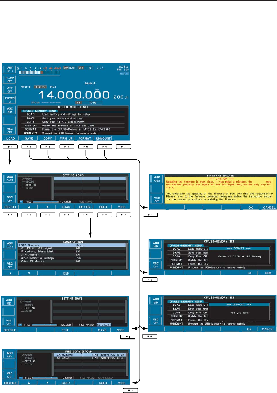
■CF card/USB-Memory set menu
DCF/USB-Memory set screen arrangement
IC-R9500IC-R9500
• CF/USB-Memory set menu
• Setting load screen (p. 11-19)
• Load option set mode (p. 11-17)
• Copy files (p. 11-21)
• Format menu (p. 11-23)
• Setting save screen (p. 11-18) • Unmount USB-Memory (p. 11-22)
• Firmware update (p. 15-4)

11-17
11
SET MODE
DLoad option set mode
Selects file loading condition from All and Select.
(default: Select) • All : Loads and sets the all following contents.
• Select : Loads and sets the selected contents only.
LOAD Contents
Select
Selects the reference signal setting loading condition
YES and NO. (default: NO). • YES : Loads and sets the reference signal setting.
• NO : Use the original reference signal setting.
REF IN/OUT, REF Adjust
NO
Selects the IP address and subnet mask setting load-
ing condition YES and NO. (default: NO). • YES : Loads and sets the IP address and subnet
mask setting.
• NO : Use the original IP address and subnet
mask setting.
IP Address, Subnet Mask
NO
Selects the CI-V address setting loading condition
YES and NO. (default: NO). • YES : Loads and sets the CI-V address setting.
• NO : Use the original CI-V address setting.
CI-V Address
NO
Selects memory channel contents and other settings
loading condition YES and NO. (default: YES). • YES : Loads and sets memory channel contents
and other settings.
• NO : Use the original memory channel contents
and other settings.
Other Memory & Settings
YES
Selects the voice RX memory loading condition YES
and NO. (default: NO). • YES : Loads and sets the voice RX memory.
• NO : Use the original the voice RX memory.
Voice RX Memory
NO
11-18
11 SET MODE
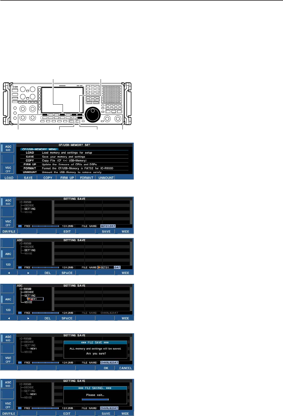
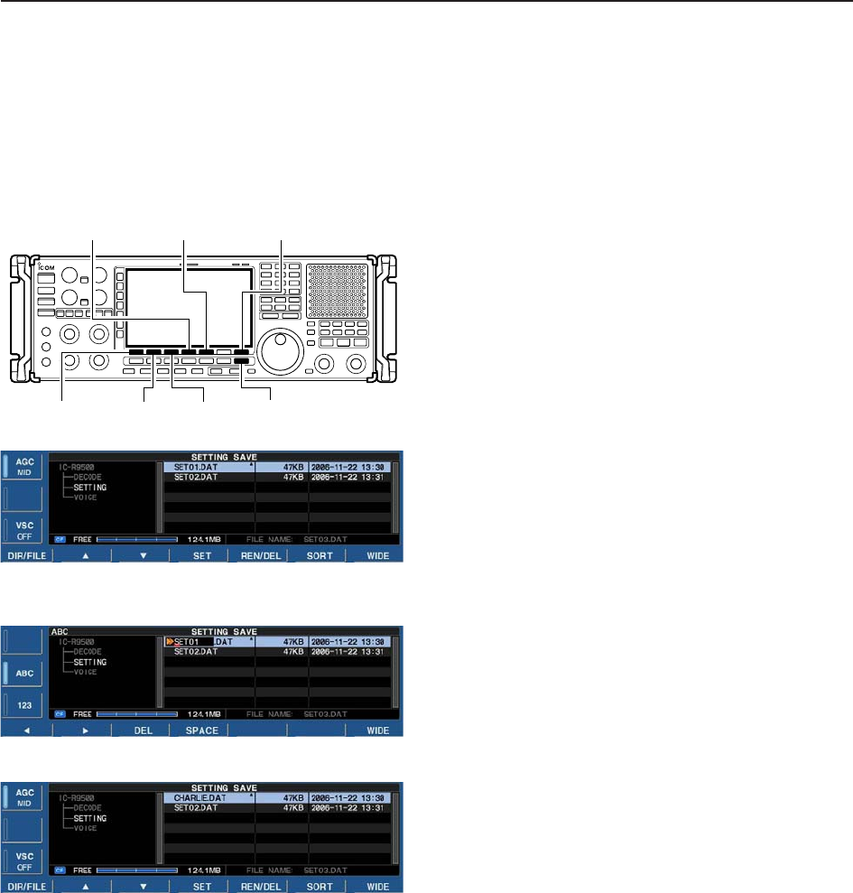
■File saving
Memory channel contents, set mode settings, etc. can
be saved into the CF (Compact Flash) memory card or
USB-memory for backup.
qDuring set mode menu screen indication, push
[F-7•CF/USB] to select CF/USB-Memory set menu
screen.
wPush [F-2•SAVE] to select setting save screen.
eChange the following conditions if desired.
• File name:
zPush [F-4•EDIT] to select file name edit con-
dition.
• Push [F-1• DIR/FILE] several times to select the
file name, if necessary.
xPush [ABC], [123] or [Symbol] to select the
character group, then rotate the main dial to
select the character.
• Push [123] or [Symbol] to toggle numerals and
symbols.
• [ABC] : A to Z (capital letters); [123]: 0 to 9 (nu-
merals); [Symbol]: ! # $ % & ‘ ` ^ + – = ( ) [ ] { } _ ~
@ can be selected.
• Push [F-1•Ω] to move the cursor left, push [F-2•≈]
to move the cursor right, push [F-3•DEL] to delete
a character and push [F-4•SPACE] to insert a
space.
cPush [EXIT/SET] to set the file name.
• Saving location
zPush [F-1•DIR/FILE] to select tree view
screen.
• Push and hold [F-1•DIR/FILE] for 1 sec. once or
twice to select the CF card or USB-Memory, when
USB memory is Inserted.
xSelect the desired directory or folder in the CF
memory card.
• Push [F-4•Ω≈] to select the upper directory.
• Push [F-2•Y] or [F-3•Z] to select folder in the
same directory.
• Push and hold [F-4•Ω≈] for 1 sec. to select a
folder in the directory.
• Push [F-5•REN/DEL] to rename the folder.
• Push and hold [F-5•REN/DEL] for 1 sec. to delete
the folder.
• Push and hold [F-6•MAKE] for 1 sec. to making a
new folder. (Edit the name with the same manner
as the “• File name” above.)
cPush [F-1•DIR/FILE] twice to select the file
name.
rPush [F-6•SAVE].
• Confirmation screen appears.
tPush [F-6•OK] to save.
• After saving is completed, return to CF/USB-Memory set
menu automatically.
[F-1•DIR/FILE]
[F-4•EDIT]
[F-6•SAVE]/[F-6•OK]
[F-7•WIDE]/[F-7•CANCEL]
[EXIT/SET] Main dial
11-19
11
SET MODE
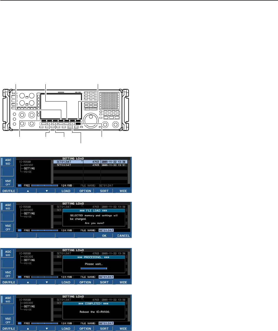
■File loading
By loading the saved setting file from the CF memory
card or USB-Memory, you can easily set up another
IC-R9500—several operators settings can easily be
applied to one IC-R9500.
qDuring set mode menu screen indication, push
[F-7•CF/USB] to select CF/USB-Memory set menu
screen.
wPush [F-1•LOAD] to select setting load screen.
ePush [F-5•OPTION] to select load option set mode,
then set the desired loading conditions, if desired.
• See page 11-17 for details.
rPush and hold [F-1•DIR/FILE] for 1 sec. once or
twice to select the CF card or USB-Memory, when
USB memory is Inserted.
tPush [F-2•Y] or [F-3•Z] to select the desired set-
ting file.
yPush [F-4•LOAD].
• Confirmation screen appears.
uPush [F-6•OK] to starts loading.
• After the loading is completed, the message dialog, “Re-
boot the IC-R9500,” appears.
iTurn the receiver power OFF then ON to make the
setting effective.
[F-1•DIR/FILE]
[F-5•OPTION][F-4•LOAD]
[F-6•SORT]/[F-6•OK]
[F-7•WIDE]/[F-7•CANCEL]
[F-3•Z][F-2•Y][EXIT/SET]
11-20
11 SET MODE
■Changing the file name
The file name, saved in the CF memory card or USB-
memory, can be re-named from the receiver as de-
sired.
qDuring setting save screen display, push
[F-1•DIR/FILE] to select tree view screen.
• Push and hold [F-1•DIR/FILE] for 1 sec. once or twice
to select the CF card or USB-Memory, when USB mem-
ory is Inserted.
• Push [F-2•Y] or [F-3•Z] to select the desired folder.
• “DECODE,” “SETTING” and “VOICE” folders are avail-
able as the default.
• After the folder is selected, push and hold [F-4•Ω≈] for
1 sec. to display content folder(s), if available.
wPush [F-1•DIR/FILE] to select file list screen.
ePush [F-2•Y] or [F-3•Z] to select the desired file.
rPush [F-5•REN/DEL] momentarily to select the file
name edit condition.
tPush [ABC], [123] or [Symbol] to select the charac-
ter group, then rotate the main dial to select the
character.
• Push [123] or [Symbol] to toggle numerals and symbols.
• [ABC] : A to Z (capital letters); [123]: 0 to 9 (numerals);
[Symbol]: ! # $ % & ‘ ` ^ + – = ( ) [ ] { } _ ~ @ can be se-
lected.
• Push [F-1•Ω] to move the cursor left, push [F-2•≈] to
move the cursor right, push [F-3•DEL] to delete a char-
acter and push [F-4•SPACE] to insert a space.
• Using the receiver’s keypad, [0]–[9], can also enter nu-
merals.
yPush [EXIT/SET] to set the file name.
[F-1•DIR/FILE]
[F-5•REN/DEL][F-4•Ω≈][F-7•WIDE]
[F-3•Z][F-2•Y][EXIT/SET]
11-21
11
SET MODE
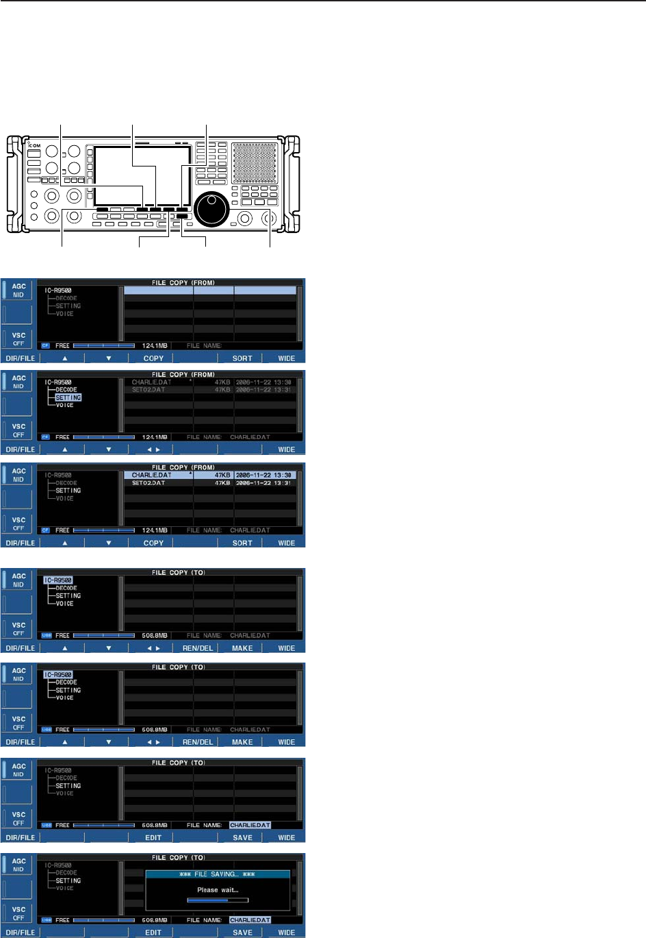
■File copying
Memory channel contents, set mode settings, etc. in
CF card or USB-Memory can be copied between
memory devices for backup.
qDuring set mode menu screen indication, push
[F-7•CF/USB] to select CF/USB-Memory set menu
screen.
wPush [F-3•COPY] to select file copy screen.
• Select the original file
(Example Copying CF card to USB-Memory)
zPush [F-1•DIR/FILE] to select tree view screen.
• Push and hold [F-1•DIR/FILE] for 1 sec. to select the
CF card, if USB-Memory is selected.
• Push [F-2•Y] or [F-3•Z] to select the desired folder.
• After the folder is selected, push and hold [F-4•Ω≈]
for 1 sec. to display content folder(s), if available.
xPush [F-1•DIR/FILE] to select file list screen.
cPush [F-2•Y] or [F-3•Z] to select the desired file.
vPush [F-4•COPY] to select the file.
• Saving location
zPush and hold [F-1•DIR/FILE] for 1 sec. to select
the USB-Memory.
xSelect the desired directory or folder in the USB-
Memory.
• Push [F-4•Ω≈] to select the upper directory.
• Push [F-2•Y] or [F-3•Z] to select folder in the same
directory.
• Push and hold [F-4•Ω≈] for 1 sec. to select a folder
in the directory.
• Push [F-5•REN/DEL] to rename the folder.
• Push and hold [F-5•REN/DEL] for 1 sec. to delete the
folder.
• Push [F-6•MAKE] for 1 sec. to making a new folder
cPush [F-1•DIR/FILE] twice to select the file
name.
ePush [F-6•SAVE].
• After saving is completed, return to CF/USB-Memory set
menu automatically.
[F-1•DIR/FILE]
[F-4•EDIT]
[F-6•SAVE]
[F-7•WIDE]
[EXIT/SET] Main dial
[F-4•COPY]
11-22
11 SET MODE
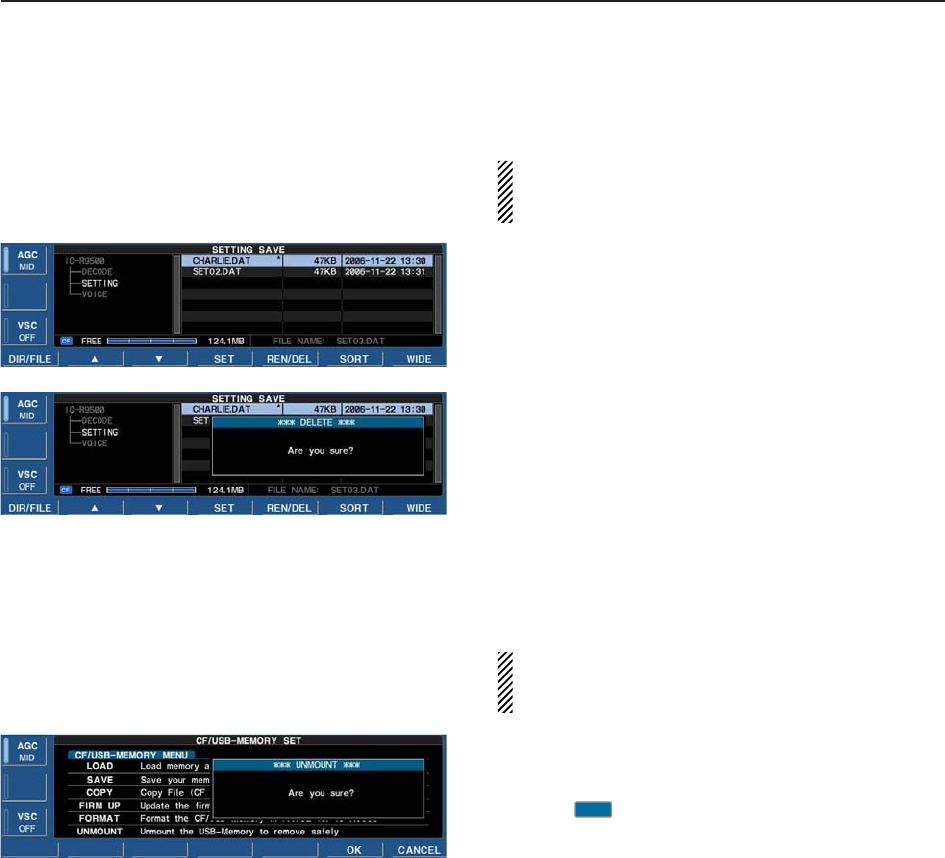
■Deleting a file
RECOMMENDATION! Deleting the setting file is ir-
reversible. Confirm the contents before deleting a
setting file!
qDuring setting save screen display, push
[F-1•DIR/FILE] to select tree view screen.
• Push [F-2•Y] or [F-3•Z] to select the desired folder.
• “DECODE,” “SETTING” and “VOICE” folders are avail-
able as the default.
• After the folder is selected, push and hold [F-2•Ω≈] for
1 sec. to display content folder(s), if available.
wPush [F-1•DIR/FILE] to select file list screen.
ePush [F-2•Y] or [F-3•Z] to select the desired file to
be deleted.
rPush and hold [F-5•REN/DEL] for 1 sec.
• Confirmation screen appears.
tPush [F-6•OK] to delete.
• After the deleting, return to setting save screen auto-
matically.
■Unmount an USB-Memory
CAUTION! When removing the USB-Memory, un-
mount operation is necessary. Unless otherwise in-
side data of USB-Memory may be dameged.
qPush and hold [F-6•UNMOUNT] for 1 sec.
• Confirmation screen appears.
wPush [F-6•OK] to unmount the USB-Memory.
eAfter “ ” indication disappers, remove the USB-
Memory.
USB
11-23
11
SET MODE
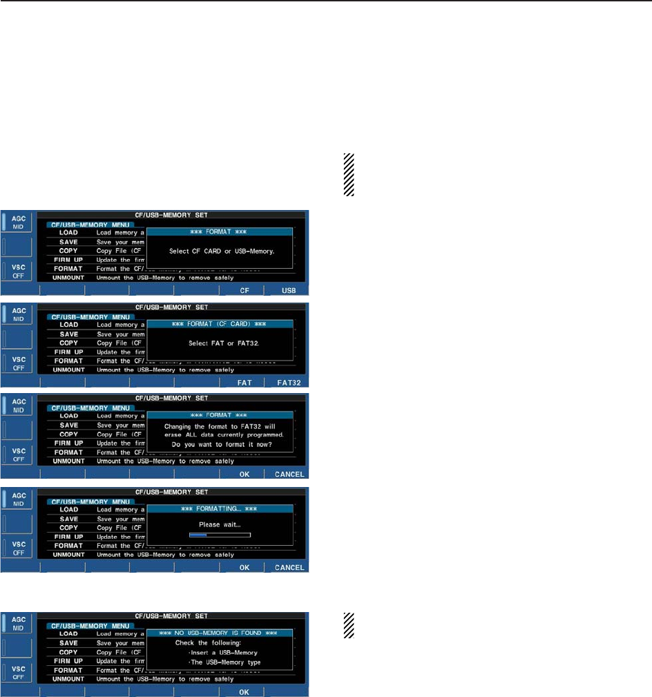
■Formatting the CF card or USB-Memory
Saved data in the CF card or USB-Memory can be
erased.
IMPORTANT! Formatting erases all saved data in
the CF card/USB-Memory. Backing up your memory
device on your PC is recommended.
qDuring CF/USB-Memory set menu display, push
and hold [F-4•FORMAT] for 1 sec.
• Selection screen appears.
wPush [F-6•CF] or [F-7•USB] to select CF card or
USB-Memory, respectively.
ePush [F-6•FAT] or [F-7•FAT32] to select the format
type, FAT or FAT32, respectively.
• Confirmation screen appears.
rPush [F-6•OK] to format.
• Push [F-7•CANCEL] to cancel.
tReturns to CF card set menu indication automati-
cally.
NOTE: If no USB-Memory is inserted and [F-7•USB]
is selected as in step w, an error message appears.
11-24
11 SET MODE
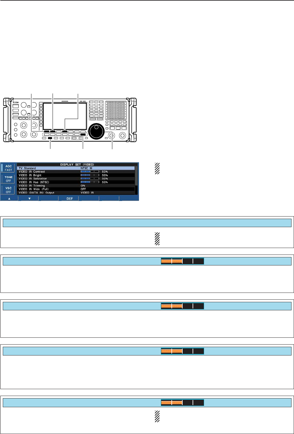
■Display set (Video) mode
This set mode is used to set the HSB (Hue,
Saturation, Brightness) color setting for video input or
output, etc.
NOTE: “Display set mode” is described on page 11-8.
qPush [DISPLAY] momentarily to turn the mini TV
screen, if necessary.
wPush and hold [DISPLAY] for 1 sec. to select the
display set (Video) mode.
ePush [F-1•Y] or [F-2•Z] to select the desired set
item.
rSet the desired condition using the main dial.
• Push and hold [F-4•DEF] for 1 sec. to select a default
condition or value.
tPush [EXIT/SET] to exit from set mode.
NOTE: Video output from [DATA IN] is available an
NTSC system only.
[EXIT/SET][DISPLAY] Main dial
[F-1•Y] [F-2•Z][F-4•DEF]
Adjusts the saturation (vibrancy of the color) of the
video signal from [VIDEO IN] jack. Adjustable range
is 0 (shade of gray) to 100% (vivid color) in 1% steps.
(default: 50%)
Adjusts the hue (color type) of the video signal from
[VIDEO IN] jack. Adjustable range is 0 (red) to 100
(green) in 1 steps. (default: 50)
NOTE: This setting is available when NTSC sys-
tem signal is input from [VIDEO IN] connector.
VIDEO IN Saturation
50%
VIDEO IN Hue (NTSC)
50%
Adjusts the LCD contrast of the video signal from
[VIDEO IN] jack. Adjustable range is 0 (low contrast)
to 100% (high contrast) in 1% steps. (default: 50%)
VIDEO IN Contrast
50%
Adjusts the LCD brightness of the video signal from
[VIDEO IN] jack. Adjustable range is 0 (dark) to 100%
(bright) in 1% steps. (default: 50%)
VIDEO IN Bright
50%
Selects the TV system of your local area from “NTSC
M,” “PAL B/G,” “PAL I,” “PAL D” and “SECAM K.” NOTE: Default setting is different depending on
versions.
TV Standard
NTSC M
11-25
11
SET MODE
Trims the frame of the video signal from [VIDEO IN]
jack. (default: ON) OFF : Displays the entire area of video signal.
ON : Cuts the frame area (each 4% width of upper,
bottom, left and right areas) and expands the
rest of area.
Selects the wide screen capability ON and OFF.
NOTE: This setting is effective for the full screen
only.
VIDEO IN Trimmin
g
ON
VIDEO IN Wide (Full)
ON
■Display set (Video) mode (continued)
Selects the output video signal from pin 2 of [DATA
IN] socket. (default: VIDEO IN) VIDEO IN : Outputs a video signal that is the same as
the input from [VIDEO IN] jack.
LCD : Outputs a video signal that is the same as
the LCD.
Adjusts the horizontal width of the output video signal
from pin 2 of [DATA IN] socket. Adjustable range is 1
(narrow) to 4 (wide) in 1 steps. (default: 1)
VIDEO (DATA IN) Output
VIDEO IN
VIDEO Out Horizontal Size
1
Selects the setup level of the output video signal from
pin 2 [DATA IN] socket. Selectable items are 0IRE
(JPN NTSC) or 7.5IRE (USA NTSC).
NOTE: Default setting is different depending on
versions.
Adjusts the saturation (vibrancy of the color) of the
output video signal from pin 2 of [DATA IN] jack. Ad-
justable range is 0 (shade of gray) to 100% (vivid
color) in 1% steps. (default: 80%)
VIDEO Out Setup Level
7.5IRE
VIDEO Out Saturation
80%
Adjusts the hue (color type) of the output video signal
from pin 2 of [DATA IN] jack. Adjustable range is 0
(red) to 100 (green) in 1 steps. (default: 50)
VIDEO Out Hue
50%
11-26
11 SET MODE
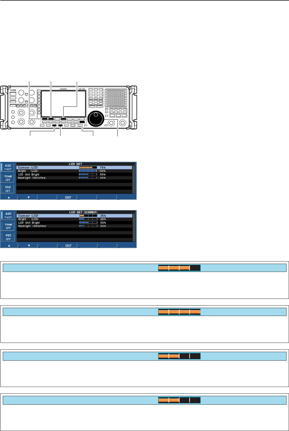
■LCD set mode
This set mode is used to set the LCD contrast, bright-
ness and other settings for 2 condition of the dimmer
function ON and OFF.
qPush [LCD SET] to select LCD set mode.
wPush [DIMMER] once or twice to select the dimmer
function ON or OFF.
ePush [F-1•Y] or [F-2•Z] to select the desired set
item.
rSet the desired condition using the main dial.
• Push and hold [F-4•DEF] for 1 sec. to select a default
condition or value.
• Push and hold [DIMMER] for 1 sec. to reset to a default
condition or value for all items at the same time.
tPush [DIMMER] once to select the other dimmer
setting, and repeat steps eand r.
• Dimmer function OFF yPush [EXIT/SET] to exit from set mode.
• Dimmer function ON
[EXIT/SET][DIMMER] [LCD SET] Main dial
[F-1•Y] [F-2•Z][F-4•DEF]
Adjusts the brightness of LCD unit from 0 (dark) to
100% (bright) range in 1% steps. Default setting:
Dimmer function OFF : 50%
Dimmer function ON : 50%
Adjusts the brightness of switch indicators from 1
(dark) to 100 (bright) range in 1 steps. Default setting:
Dimmer function OFF : 50%
Dimmer function ON : 25%
LCD Unit Bright
50%
Backlight (Switches)
50%
Adjusts the contrast of the LCD from 0 (low contrast)
to 100% (high contrast) range in 1% steps. Default setting:
Dimmer function OFF : 75%
Dimmer function ON : 25%
Contrast (LCD)
75%
Adjusts the brightness of the LCD from 0 (dark) to
100% (bright) range in 1% steps. Default setting:
Dimmer function OFF : 100%
Dimmer function ON : 25%
Bright (LCD)
100%

12-1
MAINTENANCE Section 12
■Troubleshooting ……………………………………………………… 12-2
DReceiver power …………………………………………………… 12-2
DReceiving …………………………………………………………… 12-2
DScanning …………………………………………………………… 12-3
DDisplay ……………………………………………………………… 12-3
DVoice recorder ……………………………………………………… 12-3
DFormat memory media …………………………………………… 12-3
■Screen type selection ………………………………………………… 12-4
■Main dial brake adjustment ………………………………………… 12-4
■Frequency calibration (approximate) ……………………………… 12-5
■Opening the receiver’s case ………………………………………… 12-6
■Opening the shield case ……………………………………………… 12-6
■UT-122 installation …………………………………………………… 12-7
■Clock backup battery replacement ………………………………… 12-7
■Fuse replacement …………………………………………………… 12-8
DAC power input fuse ……………………………………………… 12-8
DDC output fuse ……………………………………………………… 12-8
■Resetting the CPU …………………………………………………… 12-9
■Screen Saver Function ……………………………………………… 12-9

■Troubleshooting
The following chart is designed to help you correct
problems which are not equipment malfunctions.
If you are unable to locate the cause of a problem or
solve it through the use of this chart, contact you near-
est Icom Dealer or Service Center.
DReceiver power
DReceiving
PROBLEM POSSIBLE CAUSE SOLUTION REF.
No sounds come out from
the speaker.
Sensitivity is too low, and
only strong signals are
audible.
Received audio is unclear
or distorted.
The [ANT] switch does not
function
[AFC] cannot be turned
ON.
[AUTOTUNE](AFC) can-
not be turned ON.
[VSC] cannot be turned
ON.
[ANF] cannot be turned
ON.
[NOTCH1]/[NOTCH2]
cannot be turned ON.
The filter width cannot be
changed.
A synthesized voice is not
emitted when pushing
[SPCH].
• Volume level is too low.
• The squelch is closed.
• The RF gain is too decreases sensitivity.
• The antenna is not connected properly.
• The attenuator is activated.
• A different antenna for HF band is selected.
• Wrong operating mode is selected.
• PBT function is activated.
• Noise blanker is turned ON when receiving a
strong signal.
• Preamp is activated.
• The noise reduction is activated and the [NR]
control is too far clockwise.
• The selected frequency is above 30 MHz.
• The operating mode is not set in FM or WFM
mode.
• The operating mode is set in FM, WFM, FSK
or P25 mode.
• The operating mode is set in CW, FSK or P25
mode.
• The operating mode is not set in FM or WFM
mode.
• The operating mode is set in FM, WFM or P25
mode.
• The operating mode is set in WFM or P25
mode.
• “SPEECH Mix” in the others set mode is OFF.
• Rotate [AF] clockwise to obtain a suitable lis-
tening level.
• Turn [SQL] to 10 o’clock position to open the
squelch.
• Rotate [RF GAIN] clockwise to obtain an
enough sensitivity.
• Re-connect the antenna.
• Push [ATT] several times to select “ATT OFF.”
• Push [ANT] several times to select the correct
antenna for the HF band.
• Select a suitable operating mode.
• Push [PBT CLR] for 1 sec. to reset the function.
• Push [NB] to turn the noise blanker OFF.
• Push [P.AMP] once or twice to turn the function
OFF.
• Set the [NR] control for maximum readability.
• Select a frequency below 30 MHz.
• Select FM or WFM mode to activate AFC.
• Select AM, SSB or CW mode to activate AUTO-
TUNE.
• Select FM, WFM, AM or SSB mode to activate
VSC.
• Select FM or WFM mode to activate ANF.
• Select AM, SSB, CW and FSK mode to activate
MN1/MN2.
• Select FM, AM, SSB, CW and FSK mode.
• Set “SPEECH Mix” to All or Operation in the set
mode.
p. 3-8
p. 3-8
p. 3-8
—
p. 5-9
p. 9-3
p. 3-7
p. 5-11
p. 5-15
p. 5-9
p. 5-16
pgs. 3-4,
9-3
pgs. 3-7,
5-17
pgs. 3-7,
5-17
pgs. 3-7,
8-3
pgs. 3-7,
5-16
pgs. 3-7,
5-16
pgs. 3-7,
5-12
p. 11-11
PROBLEM POSSIBLE CAUSE SOLUTION REF.
12-2
12 MAINTENANCE
Power does not come on
when the [POWER] switch
is pushed.
• Power cable is improperly connected.
• The internal power supply is turned OFF.
• The fuse is blown.
• Re-connect the AC power cable correctly.
• Turn the internal power supply ON.
• Check for the cause, then replace the fuse.
—
p. 3-2
p.12-8

DScanning
DDisplay
DVoice recorder
DFormat memory media
12-3
12
MAINTENANCE
PROBLEM POSSIBLE CAUSE SOLUTION REF.
Programmed scan does
not stop.
Scan does not start.
(Programmed scan)
(Memory scan)
(Select memory scan)
(Mode select memory scan)
(∂F scan)
(Auto memory write scan)
• Squelch is open.
•
The same frequencies have been programmed
in scan edge memory channels PxA and PxB.
• 2 or more memory channels have not been
programmed.
• 2 or more memory channels have not been
designated as select channels.
• 2 or more memory channels with desired
mode have not been programmed.
• The center frequency for ∂F scan does not
programmed.
• Auto write bank is full.
• Readjust the [SQL] threshold.
• Program different frequencies in scan edge
memory channel PxA and PxB.
• Program more than 2 memory channels.
• Designate more than 2 memory channels as
select channels for the scan.
• Program more than 2 memory channels with
desired operating mode.
• Program the center frequency for ∂F scan.
• Clear the memory channels of auto write bank.
pgs. 3-8,
8-3
p. 8-6
pgs. 7-4,
8-11
p. 8-12
pgs. 7-4,
8-14
p. 8-8
pgs. 7-7,
8-4
PROBLEM POSSIBLE CAUSE SOLUTION REF.
The displayed frequency
does not change properly.
The key operation on the
front panel does not func-
tion.
• The dial lock function is activated.
• The panel lock function is activated.
•
Push [LOCK] to turn the function OFF.
• Push [PANEL LOCK] to turn the function OFF.
p. 9-2
p. 9-2
PROBLEM POSSIBLE CAUSE SOLUTION REF.
The voice recorder cannot
record.
The voice recorder stops
recording.
• The selected memory media is full.
• The recording memory media is full.
• The recording file size is at maximum (2 GB).
•
Select a different memory media or clear the
unnecessary files.
•
Select a different memory media or clear the
unnecessary files.
• Select a lower sound quality for long duration
recording.
p. 6-4
p. 6-4
p. 6-6
PROBLEM POSSIBLE CAUSE SOLUTION REF.
Format error appears
when formatting in FAT32
Format error appears
when formatting in FAT
• The inserted memory media capacity is small-
er than 64 MB.
• The inserted memory media capacity is larger
than 2 GB.
•
Insert a memory media larger than 64 MB or
select the FAT format.
•
Insert a memory media smaller than 2 GB or
select the FAT32 format.
p. 11-23
p. 11-23
12-4
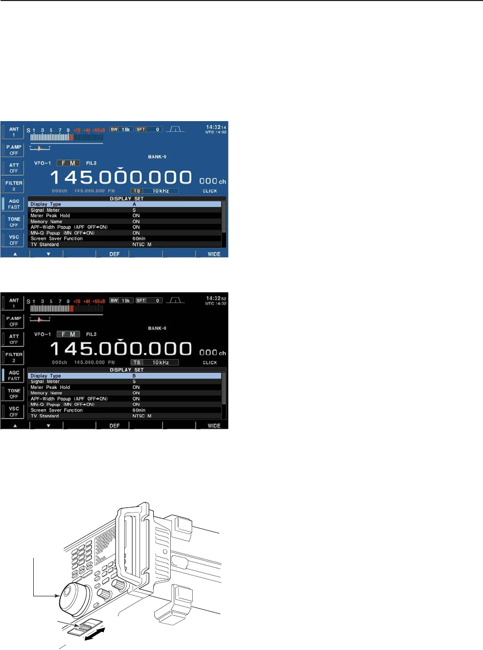
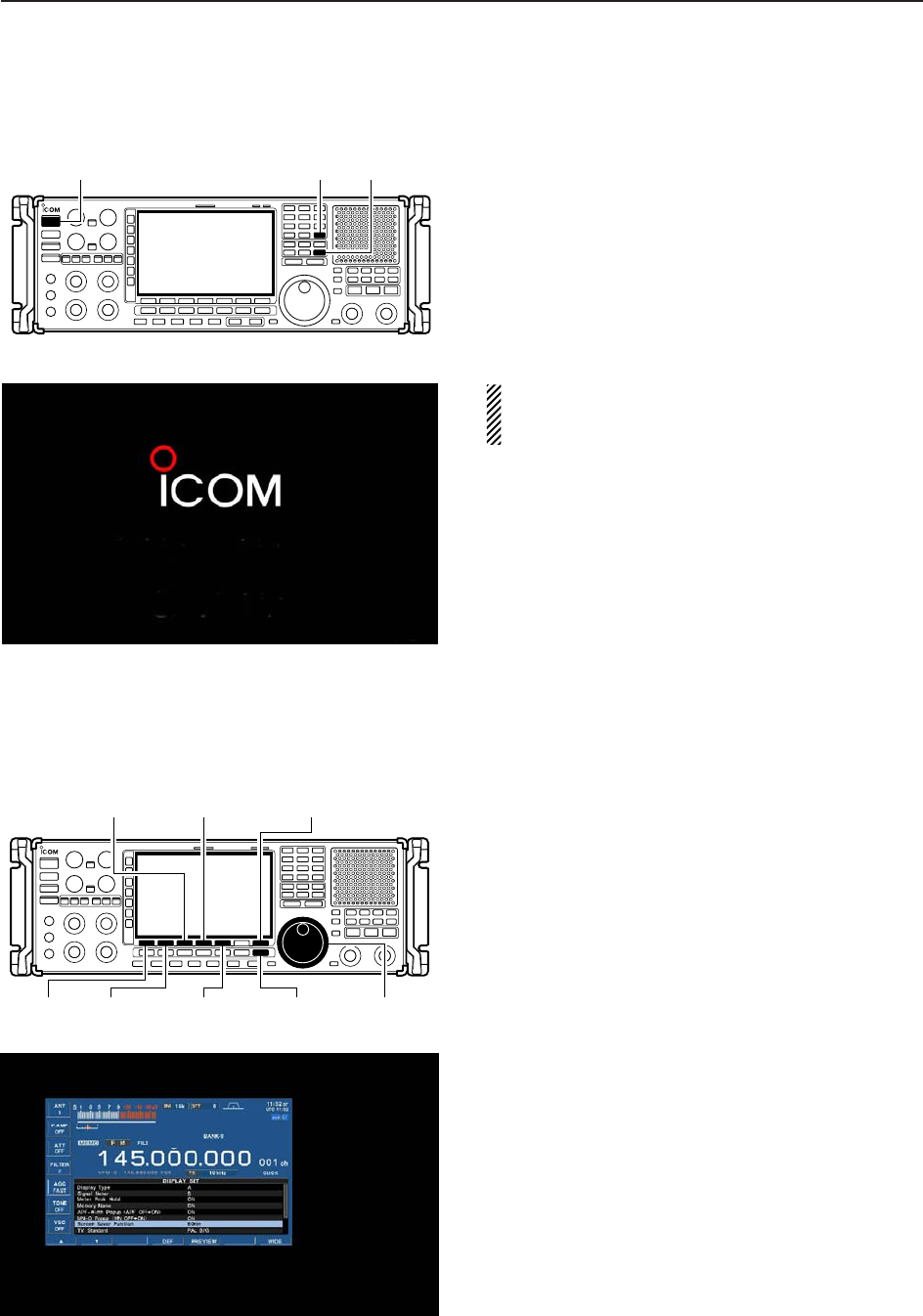
■Screen type selection
2 types of screen images are available in the IC-
R9500.
qPush [EXIT/SET] several times to close multifunc-
tion screen, if necessary.
wPush [F-7•SET] to select set mode menu screen.
ePush [F-3•DISP] to enter the display set mode.
rPush [F-1•Y] or [F-2•Z] to select “Display Type”
item.
tRotate the main dial to select the desired screen
image.
• Screen image is selectable from A and B.
yPush [EXIT/SET] twice to exit from the display set
mode.
(Blue display)
• Screen image example— type B
(Black display)
■Main dial brake adjustment
The tension of the main dial may be adjusted to suit
your preference.
The brake adjustment is located on the bottom side of
the front panel. See the figure at left.
Slide the brake adjustment to a comfortable tension
level while turning the dial continuously and evenly in
one direction.
Light
Heavy
[MAIN DIAL]
Brake
adjustment
12 MAINTENANCE
• Screen image example— type A (default)
12-5
■Frequency calibration (approximate)
A very accurate frequency counter is required to cali-
brate the frequency of the receiver. However, a rough
check may be performed by receiving radio station
WWV, WWVH, or other standard frequency signals.
CAUTION: The IC-R9500 has been thoroughly ad-
justed and tested at the factory before being
shipped. You should not have to re-calibrate it.
qPush [SSB] to select USB mode.
wPush and hold [PBT CLEAR] for 1 sec. to clear the
PBT setting.
eSet the frequency to the standard frequency station
minus 1 kHz.
• When receiving WWV or WWVH (at 15.00000 MHz) as
a standard frequency, set the operating frequency for
14.99900 MHz.
• Other standard frequencies can be used.
rPush [EXIT/SET] several times to close a multi-
function screen, if necessary.
tPush [F-7•SET] to select set mode menu screen.
• Calibration marker item yPush [F-5•OTHERS] to enter the others set mode.
uPush [F-1•Y] several times to select the “Calibra-
tion Marker” item.
iRotate the main dial clockwise to turn the calibra-
tion marker ON.
oPush [EXIT/SET] once to return to set mode menu
screen.
!0 Push [F-2•ACC] to enter accessory set mode.
!1 Push [F-2•Z] several times to select the “REF Ad-
just” item.
!2 Rotate the main dial to adjust for a zero beat with
the received standard signal as shown at left.
• Zero beat means that two signals are exactly the same
frequency, resulting in a single tone being emitted.
• REF Adjust item !3 Turn the calibration marker OFF in the others set
mode.
!4 Push [EXIT/SET] twice to exit set mode.
[F-1•Y]
[F-2•ACC]/[F-2•Z]
Main dial[EXIT/SET]
[F-4•DEF] [F-7•SET]
[F-5•OTHERS]
12
MAINTENANCE
12-6
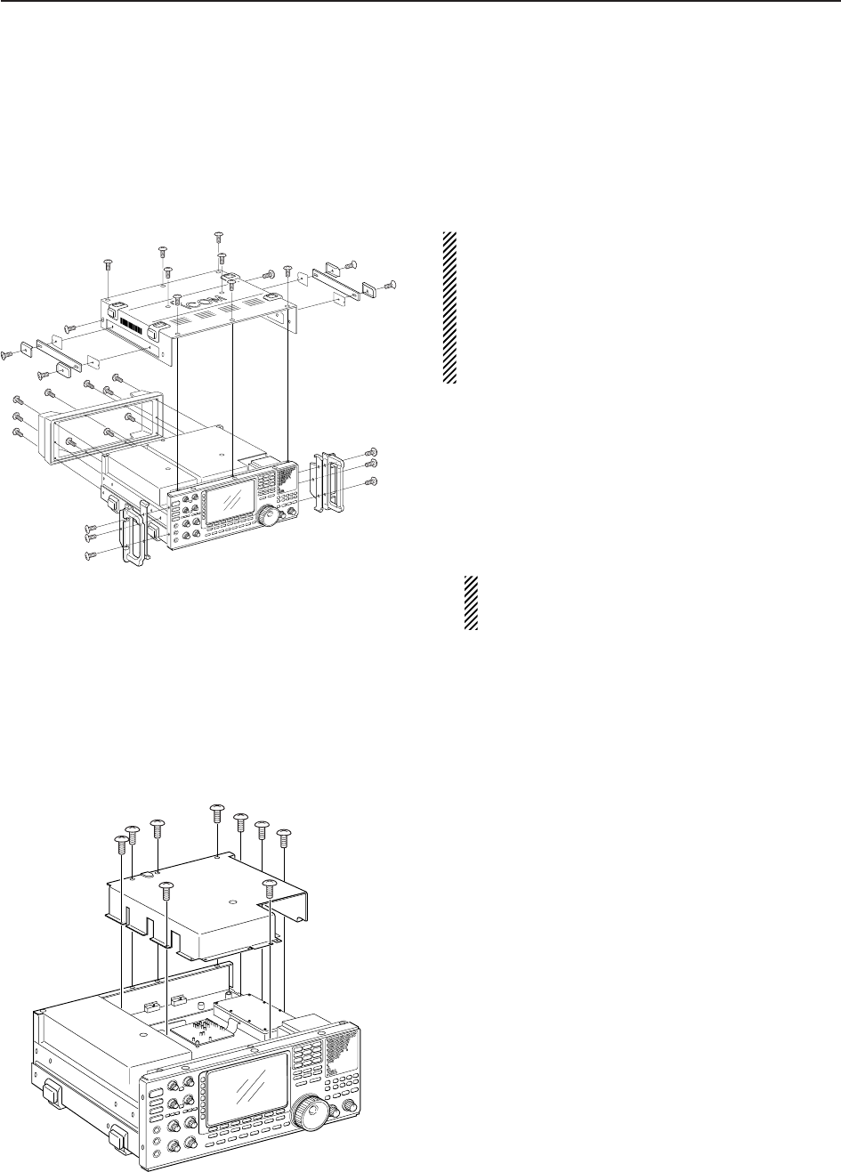
■Opening the receiver’s case
Follow the case opening procedures shown here when
you want to install the optional unit UT-122, or replace
the clock battery or internal fuse.
CAUTION!: DISCONNECT the AC power cable
from the receiver before performing any work on the
receiver. Otherwise, there is danger of electric shock
and/or equipment damage.
CAUTION!: The receiver weighs approx. 20 kg
(44 lb). Always have two people available to lift or
turn over the receiver.
qRemove the 6 screws from the rack mounting han-
dles. And remove the rack mounting handles and
side plates.
wRemove the 10 screws from the rear of the receiver
and remove the rear cover.
eRemove the 8 screws from the top of the receiver
and the 6 screws from the sides, then lift up the top
cover.
CAUTION: NEVER HOLD THE MAIN DIAL OR
ANY OTHER KNOBS when lifting the receiver.
This may damage the receiver.
■Opening the shield case
Follow the case opening procedures shown here when
you want to replace the internal fuse or optional UT-
122 installation.
qRemove the 9 screws from the shield cover of the
receiver’s top side.
wLift up the shield cover.
q
w
e
12 MAINTENANCE
12-7
12
MAINTENANCE
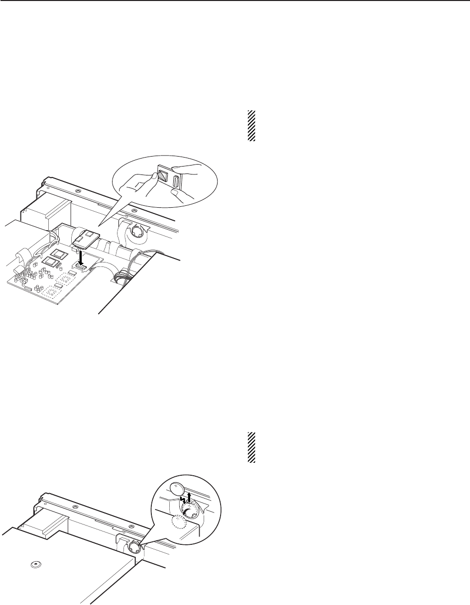
■UT-122 installation
The optional UT-122 DIGITAL UNIT provides P25 (digital)
mode operation.
WARNING: DISCONNECT the AC power cable
from the AC outlet before removing the receiver’s
cover.
qRemove the top cover and inside cover as shown
at left page.
wConnect the UT-122 as shown left.
•Remove the protective paper from the UT-122 in ad-
vance.
eReturn the inside cover and top cover and screws
to the original position.
■Clock backup battery replacement
The IC-R9500 has a lithium backup battery (CR2032)
inside for clock and timer functions. The usual life of
the backup battery is approximately 2 years.
When the backup battery is drained, the receiver re-
ceives normally but cannot retain the current time.
WARNING: DISCONNECT the AC power cable
from the AC outlet before removing the receiver’s
cover.
qRemove the top cover as shown at left page.
wReplace the clock backup battery, located on the
front panel as illustrated at left.
• Make sure the battery polarity is correct.
eReturn the top cover to the original position.
rSet the date and time in time set mode. (p. 10-2)
12-8
12 MAINTENANCE
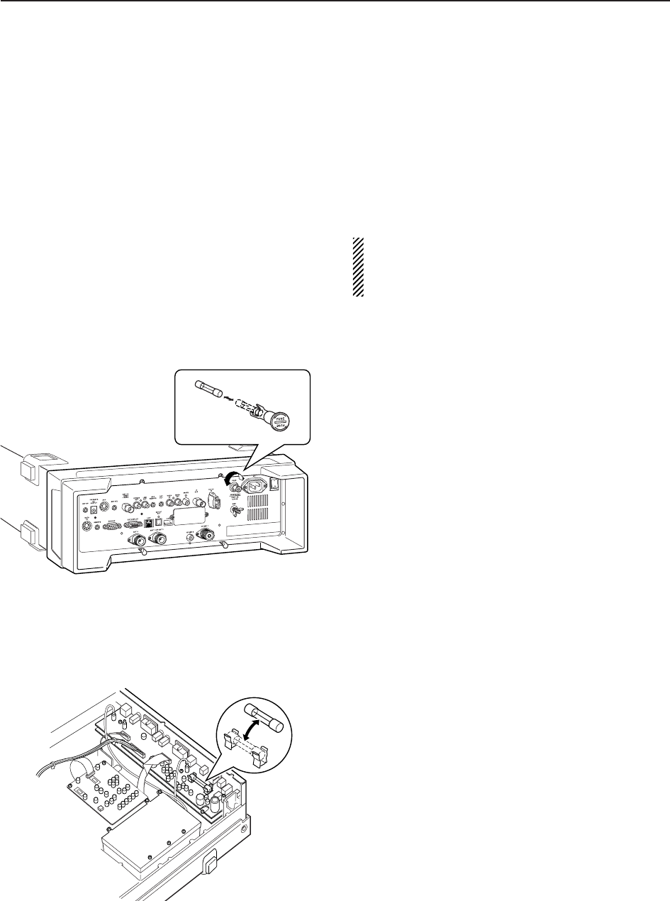
■Fuse replacement
IC-R9500 has two fuses for receiver protection.
AC power input : 4 A (for 100/120 V AC versions)
2 A (for 230/240 V AC versions)
DC output jack : 1 A
If the fuse blows or the receiver stops functioning, find
the sources of the problem, if possible, and replace the
damaged fuse with a new fuse of the same rating.
WARNING: DISCONNECT the AC power cable
from the AC outlet before removing the receiver’s
cover. This can prevent shock to the user or dam-
age to the receiver.
DAC power input fuse The AC power input fuse is held in the [FUSE] holder.
qUnscrew the [FUSE] holder using a standard screw
driver.
wReplace the open fuse with a new, properly rated
one as shown at left.
DDC output fuse When no external DC output is available from [EXT
DC] and ACC connector, the internal fuse may be
open. Replace the fuse in this case.
qRemove the top cover and shield case as shown at
page 12-6.
wReplace the open fuse with a new, properly rated
one (FGB 1 A) as shown at left.
eReplace the shield case and top cover.
12-9
12
MAINTENANCE
■Resetting the CPU
qTurn the main power switch on the rear panel ON.
• Make sure the receiver power is still OFF.
wWhile pushing and holding [CE] and [M-CL], push
[POWER] to turn power ON.
• The internal CPU is reset.
• The CPU start-up takes approx. 5 sec.
• The receiver displays its initial VFO frequencies when
resetting is complete.
eCorrect the set mode settings after resetting, if de-
sired.
NOTE: Resetting CLEARS all programmed con-
tents in memory channels and returns programmed
values in set mode to default values.
■Screen saver function
The IC-R9500 has a screen saver function to protect
the LCD from the “burn-in” effect.
qPush [EXIT/SET] several times to close a multi-
function screen, if necessary.
wPush [F-7•SET] to select set mode menu screen.
ePush [F-3•DISP] to enter the display set mode.
rPush [F-1•Y]/[F-2•Z] several times to select the
“Screen Saver Function” item.
tRotate main dial to select the desired time period
for the screen saver activation from 15, 30, 60 min.
and OFF.
• Deactivate the screen saver with “OFF” selection.
yPush [EXIT/SET] twice to exit the set mode.
[F-1•Y] [F-2•Z]Main dial[EXIT/SET]
[F-4•DEF] [F-7•SET]/[F-7•WIDE]
[F-3•DISP]
[F-5•PREVIEW]
[CE] [M-CL][POWER]
ALL CLEAR
iR9500

13-1
CONTROL COMMAND Section 13
■Remote interface (CI-V) information ………………………………… 13-2
DCI-V connection example ………………………………………… 13-2
DData format ………………………………………………………… 13-2
DCommand table …………………………………………………… 13-3
DTo send/read memory contents ………………………………… 13-10
DCodes for memory name, bank name, opening message,
and clock 2 name contents ……………………………………… 13-10
DOffset frequency setting ………………………………………… 13-10
DTone squelch frequency setting ………………………………… 13-10
DDTCS squelch code setting ……………………………………… 13-10
DNAC squelch code setting ……………………………………… 13-11
DSelective squelch code settings ………………………………… 13-11
DColor setting ……………………………………………………… 13-11
DData mode with filter width setting ……………………………… 13-11
13-2
■Remote interface (CI-V) information
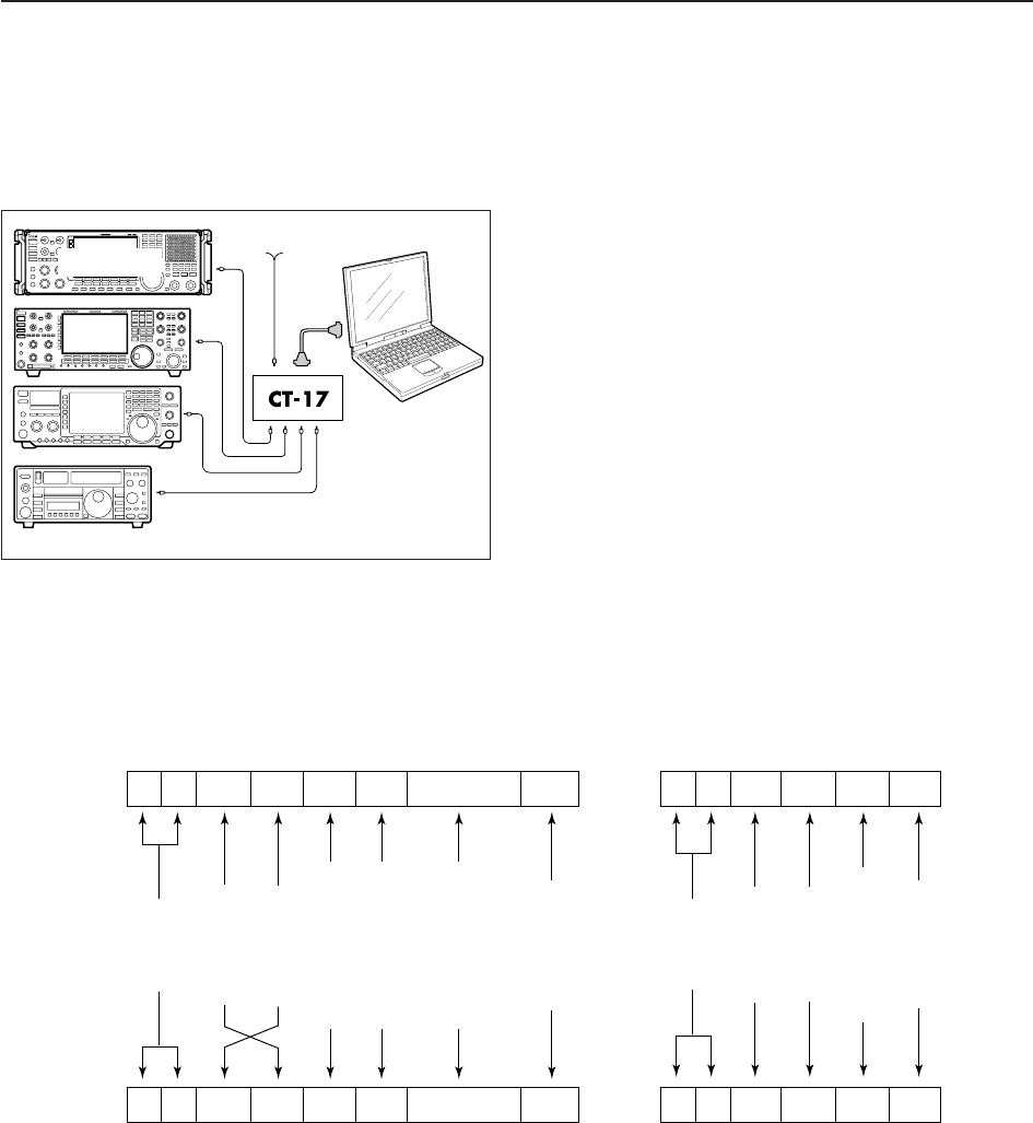
DCI-V connection example
The receiver can be connected through an optional
CT-17 CI-V LEVEL CONVERTER to a PC equipped with an
RS-232C port. The Icom Communications Interface-V
(CI-V) controls the receiver.
Up to 4 Icom CI-V transceivers or receivers can be
connected to a PC equipped with an RS-232C port.
See p. 11-14 for configuring the CI-V using set mode.
DData format The CI-V system uses the following data formats.
Data formats differ according to command numbers. A
data area or sub command is added for some com-
mands.
Controller to IC-R9500
FE FE 72H E0 Cn Sc Data area FD
Preamble
code (fixed)
Receiver’s
default address
Controller’s
default address
Command number
(see the command table)
Sub command number
(see command table)
BCD code data for
frequency or memory
number entry
End of message
code (fixed)
OK message to controller
FE FE E0 72H FB FD
FE FE E0 72H FA FD
Preamble
code (fixed)
Controller’s
default address
Receiver’s
default address
OK code
(fixed)
End of message
code (fixed)
NG message to controller
NG code
(fixed)
IC-R9500 to controller
qwert y u
FE FE E0 72H Cn Sc Data area FD
qwert y u
Personal
computer
mini-plug cable
9–15 V DC
IC-R9500
13 CONTROL COMMAND

13-3
DCommand table
13
CONTROL COMMAND
00 — Send frequency data
01 Same as Send mode data
command 06
02 — Read upper/lower frequencies for
selected band
03 — Read operating frequency
04 — Read operating mode
05 — Set operating frequency
06 00 Select LSB
01 Select USB
02 Select AM
03 Select CW
04 Select FSK
05 Select FM
07 Select CW-R
08 Select FSK-R
11 Select S-AM(D)
14 Select S-AM(L)
15 Select S-AM(U)
16 Select P25
07 — Select (Last selected) VFO mode
08 — Select memory mode
0–1219* Select memory channel
*0–999, 1000–1099 (A00–A99),
1100–1199 (S00–S99),
1200–1219 (P0A–P9A)
0–12* Select memory bank
*0–9, 10 (Bank-A), 11 (Bank-S),
12 (Bank-P)
09 — Memory write
0A — Memory to VFO
0B — Memory clear
0C — Read offset frequency
(see p. 13-10 for details)
0D — Set offset frequency
(see p. 13-10 for details)
0E 00 Scan stop
01 Programmed scan (Prog 0)/
memory scan start
02 Programmed scan (Prog 0) start
03 ∂F scan start
04 Auto memory write scan start
12 Fine programmed scan start
13 Fine ∂F scan start
22 Memory scan start
23 Select memory scan start
24 Mode select memory scan start
42 Priority scan (Prio 0) start
A0 Set ∂F scan Fixed frequency ON
AA Set ∂F scan Fixed frequency OFF
A1–A7 Set ∂F scan span (A1=±5 kHz;
A2=±10 kHz; A3=±20 kHz;
A4=±50 kHz; A5=±100 kHz;
A6=±500 kHz; A7=±1 MHz)
B0 Set as non-select channel
B1 Set as select channel
(1–9=★(SEL)1–9; when no data
command is specified, the previous-
ly set number or “★1” is selected)
B2 Set the number for select memory
scan (0=ALL; 1–9=★(SEL)1–9
D0 Set scan resume OFF
0E D1 Set scan resume ON
(Close Timer)
D3 Set scan resume ON
(Close and Delay)
10 Turn duplex OFF. (Simplex)
11 Turn duplex ON. (DUP–)
12 Turn duplex ON. (DUP+)
10 00 Select 1 Hz tuning step
01 Select 10 Hz tuning step
02 Select 100 Hz tuning step
03 Select 1 kHz tuning step
04 Select 2.5 kHz tuning step
05 Select 5 kHz tuning step
06 Select 6.25 kHz tuning step
07 Select 9 kHz tuning step
08 Select 10 kHz tuning step
09 Select 12.5 kHz tuning step
10 Select 20 kHz tuning step
11 Select 25 kHz tuning step
12 Select 100 kHz tuning step
13 Select 1 MHz tuning step
14 Select Prog tuning step
11 — Select/read attenuator (00=OFF;
06=6 dB; 10=10 dB; 12=12 dB;
18=18 dB; 20=20 dB; 24=24 dB;
30=30 dB)
12 00 Select/read the antenna below
01 30 MHz. (00=HF ANT1,
02 01=HF ANT2, 02=HF ANT3)
13 00 Announce with voice synthesizer
01 (00=all data; 01=frequency and
02 S-meter level; 02=receive mode)
14 01 + Level data [AF] level setting
(0=max. CCW to 255=max. CW)
02 + Level data [RF] level setting
(0=max. CCW to 255=11 o’clock)
03 + Level data [SQL] level setting
(0=11 o’clock to 255=max. CW)
06 + Level data [NR] level setting
(0=min. to 255=max.)
07 + Level data Left [TWIN PBT] setting or IF shift
setting (0=max. CCW, 128=center,
255=max. CW)
08 + Level data Right [TWIN PBT] setting
(0=max. CCW, 128=center,
255=max. CW)
09 + Level data [CW PITCH] setting
(0=300 Hz, 128=600 Hz,
255=900 Hz; 5 Hz steps)
0D + Level data [NOTCH1] setting
(0=low freq. to 255=high freq.)
11 + Level data [AGC] control setting (0=max.
CCW to 255=max. CW)
12 + Level data [NB] control setting
(0=max. CCW to 255=max. CW)
18 + Level data [CONTRAST] setting (0=max.
CCW to 255=max. CW)
19 + Level data [BRIGHT] setting
(0=max. CCW to 255=max. CW)
1A + Level data [NOTCH2] setting
(0=low freq. to 255=high freq.)
1B + Level data [BASS] setting
(0=max. CCW to 255=max. CW)
1C + Level data [TREBLE] setting
(0=max. CCW to 255=max. CW)
Command Sub command Description Command Sub command Description

13-4
DCommand table (continued)
13 CONTROL COMMAND
14 1D + Level data [SCAN SPEED] setting
(0=max. CCW to 255=max. CW)
1E + Level data [SCAN DELAY] setting
(0=max. CCW to 255=max. CW)
15 01 Read squelch status
02 Read signal (S-meter) level
03+Sign+M-type Read signal (dB meter) level
Sign: 0/1=+/–, M-type 0/1/2=dBµ,
dBµ[EMF], dBm
04 Read center meter level
16 02 Preamp (0=OFF; 1=preamp 1;
2=preamp 2)
12 AGC selection (0=OFF; 1=Fast;
2=Mid; 3=Slow)
22 Noise blanker
(0=OFF, 1=NB1, 2=NB2)
32 Audio peak filter (APF type is
SHARP; 0=OFF, 1=320 Hz,
2=160 Hz, 3=80 Hz), (APF type is
SOFT; 0=OFF, 1=WIDE, 2=MID,
3=NAR)
40 Noise reduction (0=OFF; 1=ON)
41 Auto notch (0=OFF; 1=ON)
43 Tone squelch (0=OFF; 1=ON)
48 Manual notch1 (0=OFF; 1=ON)
4A AFC (0=OFF; 1=ON)
4B DTCS squelch (0=OFF; 1=ON)
4C VSC (0=OFF; 1=ON)
4D Manual AGC (0=OFF; 1=ON)
4F Twin peak filter (0=OFF; 1=ON)
50 Dial lock (0=OFF; 1=ON)
51 Manual notch2 (0=OFF; 1=ON)
52 P25 Digital squelch
(0=OFF; 1=NAC, 2=SEL)
19 00 Read the receiver information
1A 00 Send/read memory contents (see
p. 13-10 for details)
03 Send/read the selected filter width
(AM: 0=200 Hz to 49=10 kHz;
SSB, CW: 0=50 Hz to 40=3600 Hz;
FSK: 0=50 Hz to 31=2700 Hz)
04 Send/read the selected AGC time
constant (AM: 0=OFF, 1=0.3 sec.
to 13=8.0 sec., SSB, CW, FSK:
0=OFF, 1=0.1 sec. to 13=6.0 sec.)
050001 Send/read FM Tone (Bass) level
(0=–15 to 30=+15)
050002 Send/read FM Tone (Treble) level
(0=–15 to 30=+15)
050003 Send/read WFM Tone (Bass)
level (0=–15 to 30=+15)
050004 Send/read WFM Tone (Treble)
level (0=–15 to 30=+15)
050005 Send/read AM Tone (Bass) level
(0=–15 to 30=+15)
050006 Send/read AM Tone (Treble) level
(0=–15 to 30=+15)
050007 Send/read SSB Tone (Bass) level
(0=–15 to 30=+15)
050008 Send/read SSB Tone (Treble)
level (0=–15 to 30=+15)
050009 Send/read CW Tone (Bass) level
(0=–15 to 30=+15)
050010 Send/read CW Tone (Treble) level
(0=–15 to 30=+15)
1A 050011 Send/read FSK Tone (Bass) level
(0=–15 to 30=+15)
050012 Send/read FSK Tone (Treble)
level (0=–15 to 30=+15)
050013 Send/read De-emphasis (FM 50k)
(0=OFF, 1=ON)
050014 Send/read De-emphasis (FM 15k)
(0=OFF, 1=ON)
050015 Send/read De-emphasis (FM 7k)
(0=OFF, 1=ON)
050016 Send/read AF high-cut filter (FM
50k) (0=OFF, 1=ON)
050017 Send/read AF high-cut filter (FM
15k) (0=OFF, 1=ON)
050018 Send/read AF high-cut filter (FM
7k) (0=OFF, 1=ON)
050019 Send/read AF high-cut filter
(WFM) (0=OFF, 1=ON)
050020 Send/read AF high-cut filter (AM)
(0=OFF, 1=ON)
050021 Send/read AF high-cut filter (SSB)
(0=OFF, 1=ON)
050022 Send/read AF high-cut filter (CW)
(0=OFF, 1=ON)
050023 Send/read AF high-cut filter (FSK)
(0=OFF, 1=ON)
050024 Send/read AF high-cut filter (P25)
(0=OFF, 1=ON)
050025 Send/read speech level
(0=0% to 255=100%)
050026 Send/read beep gain
(0=0% to 255=100%)
050027 Send/read beep gain limit
(0=OFF, 1=ON)
050028 Send/read headphones output
ratio (0=0.60 to 255=1.40)
050029 Send/read SPEECH OUTPUT
level (0=0% to 255=100%)
050030 Send/read S/P DIF output level
(0=0% to 255=100%)
050031 Send/read REC REMOTE output
(0=OFF, 1=ON)
050032 Send/read external meter output
selection
(0=Signal, 1=Signal+SQL)
050033 Send/read external meter output
level
(0=0% to 255=100%)
050034 Send/read reference signal in/out
setting (0=IN, 1=OFF, 2=OUT)
050035 Send/read reference signal fre-
quency setting
(0=0% to 255=100%)
050036 Send/read screen image type
(0=A, 1=B)
050037 Send/read signal meter type (0=S,
1=dBµ, 2=dBµ[EMF], 3=dBm
050038 Send/read meter peak hold set
(0=OFF, 1=ON)
050039 Send/read memory name indica-
tion setting (0=OFF, 1=ON)
050040 Send/read audio peak filter width
pop-up indication setting
(0=OFF, 1=ON)
050041 Send/read manual notch width
pop-up indication setting
(0=OFF, 1=ON)
Command Sub command Description Command Sub command Description

13-5
DCommand table (continued)
13
CONTROL COMMAND
1A 050042 Send/read P25 received ID pop-
up indication setting
(0=OFF, 1=ON(Dec), 2=ON(Hex))
050043 Send/read screen saver set
(0=OFF, 1=15 min., 2=30 min.,
3=60 min.)
050044 Send/read output signal setting for
external display (0=OFF, 1=ON)
050045 Send/read external display syn-
chronous pulse level setting
(0=L, 1=H)
050046 Send/read opening message indi-
cation (0=OFF, 1=ON)
050047 Send/read opening message con-
tents (see p. 13-10 for details)
050048 Send/read date
(20000101=1st Jan. 2000 to
20991231=31st Dec. 2099)
050049 Send/read time
(0000=00:00 to 2359=23:59)
050050 Send/read clock 2 function
(0=OFF, 1=ON)
050051 Send/read offset time for clock 2
(240001=–24:00 to 240000=+24:00)
050052 Send/read clock 2 name
(Up to 3-character; see p. 13-10)
050053 Send/read calibration marker
(0=OFF, 1=ON)
050054 Send/read confirmation beep
(0=OFF, 1=ON)
050055 Send/read beep audio frequency
(50=500 Hz to 200=2000 Hz)
050056 Send/read panel lock function set
(0=ALL, 1=KEY)
050057 Send/read speech language
(0=English, 1=Japanese)
050058 Send/read speech speed
(0=Slow, 1=Fast)
050059 Send/read S-level speech
(0=OFF, 1=ON)
050060 Send/read speech with a mode
switch operation (0=OFF, 1=ON)
050061 Send/read REC Speech set
(0=OFF, 1=ON)
050062 Send/read Speech Mix function
set (0=OFF, 1=Operation, 2=All)
050063 Send/read main dial auto TS
(0=OFF, 1=Low, 2=High)
050064 Send/read main dial click function
mode set (0=Manual, 1=Auto)
050065 Send/read main dial click function
set
(When above is Manual; 0=OFF,
1=ON or Auto; 0=OFF, 1=Auto)
050066 Send/read main dial click (set
mode, etc) function
(0=OFF, 1=ON)
050067 Send/read main dial operation
during scan (0=OFF, 1=Up/Down)
050068 Send/read AFC limit set
(0=OFF, 1=ON)
050069 Send/read SSB/CW synchronous
tuning function (0=OFF, 1=ON)
050070 Send/read CW normal side set
(0=LSB, 1=USB)
050071 Send/read APF type
(0=SHARP, 1=SOFT)
1A 050072 Send/read CI-V transceive set
(0=OFF, 1=ON)
050073 Send/read RS-232C function
(0=CI-V, 1=Decode)
050074 Send/read RS-232C decode
speed (0=300, 1=1200, 2=4800,
3=9600, 4=19200)
050075 Send/read keyboard type
(00=English, 01=Japanese,
02=United Kingdom, 03=French,
04=French (Canadian),
05=German, 06=Portuguese,
07=Portuguese (Brazilian),
08=Spanish, 09=Spanish (Latin
American), 10=Italian)
050076 Send/read keyboard repeat delay
(10=100 msec. to 100=1000 msec.)
050077 Send/read keyboard repeat speed
(0=2.0 cps to 31=30.0 cps)
050078 Send/read IP address set
(0000000000000001=0.0.0.1 to
0255025502550255=255.255.25
5.255)
050079 Send/read subnet mask
(1=128.0.0.0 to
30=255.255.255.252)
050080 Send/read TV type
(0=NTSC M, 1=PAL B/G, 2=PAL I,
3=PAL D, 4=SECAM K)
050081 Send/read the LCD contrast of the
video signal from [VIDEO IN]
(0=0% to 255=100%)
050082 Send/read the LCD brightness of
the video signal from [VIDEO IN]
(0=0% to 255=100%)
050083 Send/read the saturation of the
video signal from [VIDEO IN]
(0=0% to 255=100%)
050084 Send/read the hue of the video
signal from [VIDEO IN]
(0=0% to 255=100%)
050085 Send/read the frame trimming of
the video signal from [VIDEO IN].
(0=OFF, 1=ON)
050086 Send/read the wide screen set.
(0=OFF, 1=ON)
050087 Send/read the output video signal
from [DATA IN]
(0=VIDEO IN, 1=LCD)
050088 Send/read the width of the output
video signal from [DATA IN]
(0=1 (narrow) to 3=4 (wide))
050089 Send/read setup of the output
video signal from [DATA IN]
(0=0IRE (JPN NTSC), 1=7.5IRE
(USA NTSC))
050090 Send/read output saturation level
from [DATA IN]
(0=0% to 255=100%)
050091 Send/read output hue level from
[DATA IN]. (0=0% to 255=100%)
050092 Send/read the LCD contrast with
dimmer OFF condition
(0=0% to 255=100%)
050093 Send/read the LCD brightness
with dimmer OFF condition
(0=0% to 255=100%)
Command Sub command Description Command Sub command Description

13-6
DCommand table (continued)
13 CONTROL COMMAND
1A 050094 Send/read the LCD unit brightness
with dimmer OFF condition
(0=0% to 255=100%)
050095 Send/read the key backlight with
dimmer OFF condition
(0=0% to 255=100%)
050096 Send/read the LCD contrast with
dimmer ON condition
(0=0% to 255=100%)
050097 Send/read the LCD brightness
with dimmer ON condition
(0=0% to 255=100%)
050098 Send/read the LCD unit brightness
with dimmer ON condition
(0=0% to 255=100%)
050099 Send/read the key backlight with
dimmer ON condition
(0=0% to 255=100%)
050100 Send/read scope max. hold
(0=OFF, 1=ON)
050101 Send/read scope center frequen-
cy set (0=Filter center, 1=Carrier
point center, 2=Carrier point cen-
ter (Abs. Freq.))
050102 Send/read waveform color for
receiving signal
(see p. 13-11 for details)
050103 Send/read waveform color for
max. hold
(see p. 13-11 for details)
050104 Send/read marker color for receiv-
ing signal
(see p. 13-11 for details)
050105 Send/read marker color for max.
hold (see p. 13-11 for details)
050106 Send/read scope peak excursion
(0=0 dB to 80=80 dB)
050107 Send/read scope peak threshold
(0=–100 dB to 100=0 dB)
050108 Send/read voice recorder’s short
play time (3=3 sec. to 10=10 sec.)
050109 Send/read voice recorder short
record time
(5=5 sec. to 30=30 sec.)
050110 Send/read voice recorder’s
recording quality
(0=SQ1 (8 kHz), 1=SQ2 (12 kHz),
2=HQ1 (16 kHz) 3=HQ2(24 kHz)
4=SHQ (48 kHz))
050111 Send/read REC remote set
(0=OFF, 1=ON)
050112 Send/read SPEECH Mix set
(0=OFF, 1=Operation, 2=All)
050113 Send/read speech mix level
(0=0% (Receive audio only) to
255=100% (Speech audio only))
050114 Send/read memory bank limit set
for memory channel selection
(0=OFF, 1=ON)
050115 Send/read memory bank limit set
for memory scan (0=OFF, 1=ON)
050116 Send/read memory bank name
(Bank-0) (see p. 13-10 for details)
050117 Send/read memory bank name
(Bank-1) (see p. 13-10 for details)
1A 050118 Send/read memory bank name
(Bank-2) (see p. 13-10 for details)
050119 Send/read memory bank name
(Bank-3) (see p. 13-10 for details)
050120 Send/read memory bank name
(Bank-4) (see p. 13-10 for details)
050121 Send/read memory bank name
(Bank-5) (see p. 13-10 for details)
050122 Send/read memory bank name
(Bank-6) (see p. 13-10 for details)
050123 Send/read memory bank name
(Bank-7) (see p. 13-10 for details)
050124 Send/read memory bank name
(Bank-8) (see p. 13-10 for details)
050125 Send/read memory bank name
(Bank-9) (see p. 13-10 for details)
050126 Send/read memory bank name
(Bank-A) (see p. 13-10 for details)
050127 Send/read memory bank name
(Bank-S) (see p. 13-10 for details)
050128 Set/read FFT scope averaging set
for FSK decoder
(0=OFF, 1=2, 2=3, 3=4)
050129 Set/read FFT scope waveform
color set for FSK decoder
(see p. 13-11 for details)
050130 Send/read FSK decode USOS
(0=OFF, 1=ON)
050131 Send/read FSK decode new line
code
(0=CR,LF,CR+LF, 1=CR+LF)
050132 Send/read clock selection for time
stamp (0=Local time, 1=Clock 2)
050133 Send/read frequency stamp
(0=OFF, 1=ON)
050134 Send/read FSK received text font
color (see p. 13-11 for details)
050135 Send/read time stamp text font
color (see p. 13-11 for details)
050136 Send/read skip scan set
(0=OFF, 1=ON)
050137 Send/read auto memory scan
memory clear set (0=OFF,
1=[AUTO] Long Push, 2=ON)
050138 Send/read auto scan screen set
when scan start (0=OFF, 1=ON)
050139 Send/read NB1 depth
(0=1 to 9=10)
050140 Send/read NB1 width
(0=0 to 255=100)
050141 Send/read NB2 depth
(0=1 to 9=10)
050142 Send/read NB2 width
(0=0 to 255=100)
050143 Send/read TS (1 Hz) as selectable
tuning step for FM
(0=OFF, 1=ON)
050144 Send/read TS (10 Hz) as selec-
table tuning step for FM
(0=OFF, 1=ON)
050145 Send/read TS (100 Hz) as selec-
table tuning step for FM
(0=OFF, 1=ON)
050146 Send/read TS (1 kHz) as selec-
table tuning step for FM
(0=OFF, 1=ON)
Command Sub command Description Command Sub command Description

13-7
DCommand table (continued)
13
CONTROL COMMAND
1A 050147 Send/read TS (2.5 kHz) as selec-
table tuning step for FM
(0=OFF, 1=ON)
050148 Send/read TS (5 Hz) as selectable
tuning step for FM
(0=OFF, 1=ON)
050149 Send/read TS (6.25 kHz) as selec-
table tuning step for FM
(0=OFF, 1=ON)
050150 Send/read TS (9 kHz) as selec-
table tuning step for FM
(0=OFF, 1=ON)
050151 Send/read TS (10 kHz) as selec-
table tuning step for FM
(0=OFF, 1=ON)
050152 Send/read TS (12.5 kHz) as selec-
table tuning step for FM
(0=OFF, 1=ON)
050153 Send/read TS (20 kHz) as selec-
table tuning step for FM
(0=OFF, 1=ON)
050154 Send/read TS (25 kHz) as selec-
table tuning step for FM
(0=OFF, 1=ON)
050155 Send/read TS (100 kHz) as selec-
table tuning step for FM
(0=OFF, 1=ON)
050156 Send/read TS (1 MHz) as selec-
table tuning step for FM
(0=OFF, 1=ON)
050157 Send/read TS (PROG) as selec-
table tuning step for FM
(0=OFF, 1=ON)
050158 Send/read TS (1 Hz) as selectable
tuning step for WFM
(0=OFF, 1=ON)
050159 Send/read TS (10 Hz) as selec-
table tuning step for WFM
(0=OFF, 1=ON)
050160 Send/read TS (100 Hz) as selec-
table tuning step for WFM
(0=OFF, 1=ON)
050161 Send/read TS (1 kHz) as selec-
table tuning step for WFM
(0=OFF, 1=ON)
050162 Send/read TS (2.5 kHz) as selec-
table tuning step for WFM
(0=OFF, 1=ON)
050163 Send/read TS (5 Hz) as selectable
tuning step for WFM
(0=OFF, 1=ON)
050164 Send/read TS (6.25 kHz) as selec-
table tuning step for WFM
(0=OFF, 1=ON)
050165 Send/read TS (9 kHz) as selec-
table tuning step for WFM
(0=OFF, 1=ON)
050166 Send/read TS (10 kHz) as selec-
table tuning step for WFM
(0=OFF, 1=ON)
050167 Send/read TS (12.5 kHz) as selec-
table tuning step for WFM
(0=OFF, 1=ON)
050168 Send/read TS (20 kHz) as selec-
table tuning step for WFM
(0=OFF, 1=ON)
1A 050169 Send/read TS (25 kHz) as selec-
table tuning step for WFM
(0=OFF, 1=ON)
050170 Send/read TS (100 kHz) as selec-
table tuning step for WFM
(0=OFF, 1=ON)
050171 Send/read TS (1 MHz) as selec-
table tuning step for WFM
(0=OFF, 1=ON)
050172 Send/read TS (PROG) as selec-
table tuning step for WFM
(0=OFF, 1=ON)
050173 Send/read TS (1 Hz) as selectable
tuning step for AM
(0=OFF, 1=ON)
050174 Send/read TS (10 Hz) as selec-
table tuning step for AM
(0=OFF, 1=ON)
050175 Send/read TS (100 Hz) as selec-
table tuning step for AM
(0=OFF, 1=ON)
050176 Send/read TS (1 kHz) as selec-
table tuning step for AM
(0=OFF, 1=ON)
050177 Send/read TS (2.5 kHz) as selec-
table tuning step for AM
(0=OFF, 1=ON)
050178 Send/read TS (5 Hz) as selectable
tuning step for AM
(0=OFF, 1=ON)
050179 Send/read TS (6.25 kHz) as selec-
table tuning step for AM
(0=OFF, 1=ON)
050180 Send/read TS (9 kHz) as selec-
table tuning step for AM
(0=OFF, 1=ON)
050181 Send/read TS (10 kHz) as selec-
table tuning step for AM
(0=OFF, 1=ON)
050182 Send/read TS (12.5 kHz) as selec-
table tuning step for AM
(0=OFF, 1=ON)
050183 Send/read TS (20 kHz) as selec-
table tuning step for AM
(0=OFF, 1=ON)
050184 Send/read TS (25 kHz) as selec-
table tuning step for AM
(0=OFF, 1=ON)
050185 Send/read TS (100 kHz) as selec-
table tuning step for AM
(0=OFF, 1=ON)
050186 Send/read TS (1 MHz) as selec-
table tuning step for AM
(0=OFF, 1=ON)
050187 Send/read TS (PROG) as selec-
table tuning step for AM
(0=OFF, 1=ON)
050188 Send/read TS (1 Hz) as selectable
tuning step for SSB
(0=OFF, 1=ON)
050189 Send/read TS (10 Hz) as selec-
table tuning step for SSB
(0=OFF, 1=ON)
050190 Send/read TS (100 Hz) as selec-
table tuning step for SSB
(0=OFF, 1=ON)
Command Sub command Description Command Sub command Description

DCommand table (continued)
13-8
13 CONTROL COMMAND
1A 050191 Send/read TS (1 kHz) as selec-
table tuning step for SSB
(0=OFF, 1=ON)
050192 Send/read TS (2.5 kHz) as selec-
table tuning step for SSB
(0=OFF, 1=ON)
050193 Send/read TS (5 Hz) as selectable
tuning step for SSB
(0=OFF, 1=ON)
050194 Send/read TS (6.25 kHz) as selec-
table tuning step for SSB
(0=OFF, 1=ON)
050195 Send/read TS (9 kHz) as selec-
table tuning step for SSB
(0=OFF, 1=ON)
050196 Send/read TS (10 kHz) as selec-
table tuning step for SSB
(0=OFF, 1=ON)
050197 Send/read TS (12.5 kHz) as selec-
table tuning step for SSB
(0=OFF, 1=ON)
050198 Send/read TS (20 kHz) as selec-
table tuning step for SSB
(0=OFF, 1=ON)
050199 Send/read TS (25 kHz) as selec-
table tuning step for SSB
(0=OFF, 1=ON)
050200 Send/read TS (100 kHz) as selec-
table tuning step for SSB
(0=OFF, 1=ON)
050201 Send/read TS (1 MHz) as selec-
table tuning step for SSB
(0=OFF, 1=ON)
050202 Send/read TS (PROG) as selec-
table tuning step for SSB
(0=OFF, 1=ON)
050203 Send/read TS (1 Hz) as selectable
tuning step for CW
(0=OFF, 1=ON)
050204 Send/read TS (10 Hz) as selec-
table tuning step for CW
(0=OFF, 1=ON)
050205 Send/read TS (100 Hz) as selec-
table tuning step for CW
(0=OFF, 1=ON)
050206 Send/read TS (1 kHz) as selec-
table tuning step for CW
(0=OFF, 1=ON)
050207 Send/read TS (2.5 kHz) as selec-
table tuning step for CW
(0=OFF, 1=ON)
050208 Send/read TS (5 Hz) as selectable
tuning step for CW
(0=OFF, 1=ON)
050209 Send/read TS (6.25 kHz) as selec-
table tuning step for CW
(0=OFF, 1=ON)
050210 Send/read TS (9 kHz) as selec-
table tuning step for CW
(0=OFF, 1=ON)
050211 Send/read TS (10 kHz) as selec-
table tuning step for CW
(0=OFF, 1=ON)
050212 Send/read TS (12.5 kHz) as selec-
table tuning step for CW
(0=OFF, 1=ON)
1A 050213 Send/read TS (20 kHz) as selec-
table tuning step for CW
(0=OFF, 1=ON)
050214 Send/read TS (25 kHz) as selec-
table tuning step for CW
(0=OFF, 1=ON)
050215 Send/read TS (100 kHz) as selec-
table tuning step for CW
(0=OFF, 1=ON)
050216 Send/read TS (1 MHz) as selec-
table tuning step for CW
(0=OFF, 1=ON)
050217 Send/read TS (PROG) as selec-
table tuning step for CW
(0=OFF, 1=ON)
050218 Send/read TS (1 Hz) as selectable
tuning step for FSK
(0=OFF, 1=ON)
050219 Send/read TS (10 Hz) as selec-
table tuning step for FSK
(0=OFF, 1=ON)
050220 Send/read TS (100 Hz) as selec-
table tuning step for FSK
(0=OFF, 1=ON)
050221 Send/read TS (1 kHz) as selec-
table tuning step for FSK
(0=OFF, 1=ON)
050222 Send/read TS (2.5 kHz) as selec-
table tuning step for FSK
(0=OFF, 1=ON)
050223 Send/read TS (5 Hz) as selectable
tuning step for FSK
(0=OFF, 1=ON)
050224 Send/read TS (6.25 kHz) as selec-
table tuning step for FSK
(0=OFF, 1=ON)
050225 Send/read TS (9 kHz) as selec-
table tuning step for FSK
(0=OFF, 1=ON)
050226 Send/read TS (10 kHz) as selec-
table tuning step for FSK
(0=OFF, 1=ON)
050227 Send/read TS (12.5 kHz) as selec-
table tuning step for FSK
(0=OFF, 1=ON)
050228 Send/read TS (20 kHz) as selec-
table tuning step for FSK
(0=OFF, 1=ON)
050229 Send/read TS (25 kHz) as selec-
table tuning step for FSK
(0=OFF, 1=ON)
050230 Send/read TS (100 kHz) as selec-
table tuning step for FSK
(0=OFF, 1=ON)
050231 Send/read TS (1 MHz) as selec-
table tuning step for FSK
(0=OFF, 1=ON)
050232 Send/read TS (PROG) as selec-
table tuning step for FSK
(0=OFF, 1=ON)
050233 Send/read TS (1 Hz) as selectable
tuning step for P25
(0=OFF, 1=ON)
050234 Send/read TS (10 Hz) as selec-
table tuning step for P25
(0=OFF, 1=ON)
Command Sub command Description Command Sub command Description

13-9
13
CONTROL COMMAND
DCommand table (continued)
1A 050235 Send/read TS (100 Hz) as selec-
table tuning step for P25
(0=OFF, 1=ON)
050236 Send/read TS (1 kHz) as selec-
table tuning step for P25
(0=OFF, 1=ON)
050237 Send/read TS (2.5 kHz) as selec-
table tuning step for P25
(0=OFF, 1=ON)
050238 Send/read TS (5 Hz) as selectable
tuning step for P25
(0=OFF, 1=ON)
050239 Send/read TS (6.25 kHz) as selec-
table tuning step for P25
(0=OFF, 1=ON)
050240 Send/read TS (9 kHz) as selec-
table tuning step for P25
(0=OFF, 1=ON)
050241 Send/read TS (10 kHz) as selec-
table tuning step for P25
(0=OFF, 1=ON)
050242 Send/read TS (12.5 kHz) as selec-
table tuning step for P25
(0=OFF, 1=ON)
050243 Send/read TS (20 kHz) as selec-
table tuning step for P25
(0=OFF, 1=ON)
050244 Send/read TS (25 kHz) as selec-
table tuning step for P25
(0=OFF, 1=ON)
050245 Send/read TS (100 kHz) as selec-
table tuning step for P25
(0=OFF, 1=ON)
050246 Send/read TS (1 MHz) as selec-
table tuning step for P25
(0=OFF, 1=ON)
050247 Send/read TS (PROG) as selec-
table tuning step for P25
(0=OFF, 1=ON)
050248 Send/read CW pitch set
(0=300 Hz to 120=900 Hz in 5 Hz
steps)
050249 Send/read FSK RX frequency
(0=Mark(Space), 1=Mark/Space
Center)
050250 Send/read FSK tone frequency
(0=1275 Hz, 1=1500 Hz,
2=1615 Hz, 3=2125 Hz)
050251 Send/read FSK shift width
(0=170 Hz, 1=200 Hz, 2=425 Hz,
3=800 Hz,4=850 Hz )
08 Send/read DSP filter shape
(0= sharp, 1= soft)
09 Send/read roofing filter set
(FM/AM/SSB/CW/FSK; 0=3 kHz,
1=6 kHz, 2=15 kHz, 3=50 kHz,
WFM; 4=240 kHz, P25; 2=15
kHz)
0A Send/read manual notch1 width
(0=Wide, 1=Mid., 2=Nar.)
0B Send/read manual notch2 width
(0=Wide, 1=Mid., 2=Nar.)
1B 01 Set/read TSQL tone frequency.
(see p. 13-10 for details)
02 Set/read DTCS squelch code
(see p. 13-10 for details)
03 Set/read NAC squelch code
(see p. 13-11 for details)
04 Set/read TGID for selective
squelch (see p. 13-11 for details)
05 Set/read UNIT ID for selective
squelch (see p. 13-11 for details)
1D 00 Send/read remote function set
(0=OFF, 1=REMOTE1 (locks VRs
only), 2=REMOTE2 (locks VRs.
Keys,and dials)
Command Sub command Description Command Sub command Description
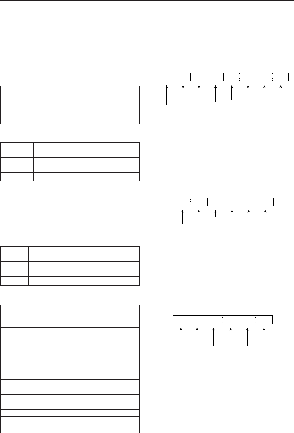
13-10
13 CONTROL COMMAND
DTo send/read memory contents
When sending or reading memory contents, additional
codes must be added to appoint the memory channel
as follows.
➥Additional code: 0000–1219
• Memory channel code
• Memory bank code
DCodes for memory name, bank name,
opening message and clock 2 name
contents
To send or read the desired memory name settings,
the character codes as follows are used.
•Character’s code
•Character’s code— Symbols
DOffset frequency setting
The following data sequence is used when sending or
reading the offset frequency setting.
DTone squelch frequency setting
The following data sequence is used when sending or
reading the tone frequency setting.
DDTCS squelch code setting
The following data sequence is used when sending or
reading the DTCS code setting.
DTCS Polarity
†, ‡: 0. 1
100 digit: 0–7
10 digit: 0–7
1 digit: 0–7
Fixed digit: 0†
Fixed digit: 0
q†
00X X X
we
X
†Not necessary when normal is set.
‡0=Normal, 1=Reverse
100Hz digit: 0–2
10 Hz digit: 0–9
1 Hz digit: 0–9
0.1 Hz digit: 0–9
Fixed digit: 0*
Fixed digit: 0*
q*
00XXX
we
X
*Not necessary when setting a frequency.
1 kHz digit: 0–9
100 Hz digit: 0 (fixed)
100 kHz digit: 0–9
10 kHz digit: 0–9
10 MHz digit: 0–9
1 MHz digit: 0–4
q
0XXXXXX
we r
0
1 GHz digit: 0 (fixed)
100 MHz digit: 0–4
Character ASCII code Description
0–9 30–39 Numerals
A–Z 41–5A Alphabetical characters
a–z 61–7A Alphabetical characters
space 20 Word space
Character ASCII code Character ASCII code
!21#23
$24%25
&26¥5C
?3F” 22
’27`60
^5E+2B
–2D✱2A
/2F.2E
,2C:3A
;3B=3D
<3C>3E
(28)29
[5B]5D
{7B}7D
|7C_5F
–7E @ 40
Code Bank number Memory Cnannel
0000–0999 Bank-0–Bank-9 0–999
1000–1099 Bank-A (Auto) A00–A99
1100–1199 Bank-S (Skip) S00–S99
1200–1219 Bank-P (Scan edge) P0A–P9B
Code Bank number
00–09 Bank-0–Bank-9
10 Bank-A (Auto)
11 Bank-S (Slip)
12 Bank-P (Scan edge)
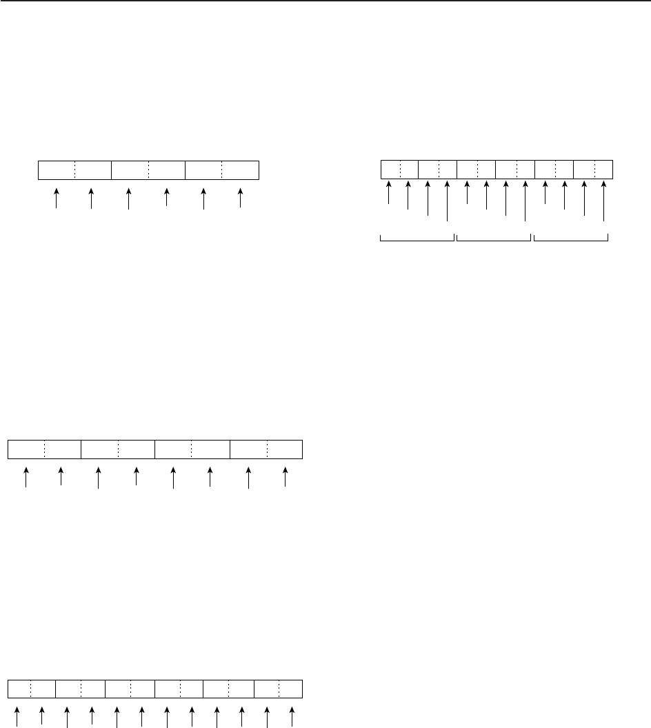
13-11
13
CONTROL COMMAND
DNAC squelch code setting
The following data sequence is used when sending or
reading the NAC code setting.
DSelective squelch code settings
•TGID setting
The following data sequence is used when sending or
reading the TGID code setting.
•UNIT ID setting
The following data sequence is used when sending or
reading the UNIT ID code setting.
DColor setting
The following data sequence is used when sending or
reading the color setting.
1000
100
10
1
q
0XXX0XXX0XXX
werty
1000
100
10
1
1000
100
10
1
R (Red) G (Green) B (Blue)
Using 0000–0255 for each color element.
2nd digit: 0–F
3rd digit: 0–F
Fixed digit: 0
Fixed digit: 0
q
0
Selectable UNIT ID: 0 0 0 0 0 1 – 9 8 9 6 7 F
0X X X
werty
Fixed digit: 0
0
1st digit: 0–F
4th digit: 0–F
X
Fixed digit: 0
0X0X0
5th digit: 0–F
Fixed digit: 0
6th digit: 0–F
Fixed digit: 0
2nd digit: 0–F
3rd digit: 0–F
Fixed digit: 0
Fixed digit: 0
q
00X X X
wer
Fixed digit: 0
Selectable TGID: 0 0 0 0 – F F F F
0
1st digit: 0–F
4th digit: 0–F
X
Fixed digit: 0
0
2nd digit: 0–F
3rd digit: 0–F
Fixed digit: 0
Fixed digit: 0
q
00X X X
we
Fixed digit: 0
0
1st digit: 0–F
Selectable NAC: 0 0 0 – F F F

14-1
SPECIFICATIONS AND OPTIONS Section 14
■Specifications ………………………………………………………… 14-2
DGeneral ……………………………………………………………… 14-2
DReceiver …………………………………………………………… 14-3
■Options ………………………………………………………………… 14-4

14-2
■Specifications
DGeneral
• Frequency coverage (unit: MHz) :
USA 0.005000–821.999999, 851.000000–866.999999
896.000000–3335.000000
France 0.050000–29.999999, 50.200000–51.200000,
87.500000–108.000000, 144.000000–146.000000,
430.000000–440.000000, 1240.000000–1300.000000
Europe, U.K., Canada, EXP, Australia 0.005000–3335.000000
• Operating mode : USB, LSB, CW, FSK, AM, FM, WFM, P25
• Number of memory channels : 1220 (1000 regular channels, 100 auto memory write
channels, 100 skip channels, 20 scan edge channels)
• Antenna connector : Type-N×2 (antenna impedance: 50 ),
SO-239×1 (antenna impedance: 50 ),
Phono (RCA)×1 (antenna impedance: 500 )
• Operating temperature range : 0˚C to +50˚C; +32˚F to +122˚F
• Frequency stability : Less than ±0.05 ppm (approx. 5 min. after from turn the
main power, [I/O], ON, 0–50˚C; 32–122˚F)
• Frequency resolution : 1Hz
• Power supply requirement : 100 V, 120 V, 230 V, 240 V AC
• Power consumption :
Receive Stand-by Less than 100 VA
Max. audio Less than 100 VA
• Dimensions (projections not included) :424×149×340 mm; 1611⁄16×57⁄8×133⁄8in
• Weight : Approx. 20 kg; 44 lb
• ACC connector : 8-pin DIN connector
• DATA IN connector : 8-pin DIN connector
• Display*:7-inch (diagonal) TFT color LCD (800×480)
• EXT-DISPLAY connector : D-sub 15S
• RS-232C connector : D-sub 9-pin
• VIDEO IN connector : Phono (RCA)
• VIDEO OUT connector : Phono (RCA)
• SPEECH OUT connector : Phono (RCA)
• LINE OUT connector : Phono (RCA)
• USB connector : USB (Universal Serial Bus)1.1/2.0
• CI-V connector : 2-conductor 3.5 (d) mm (1⁄8w)
• ANT-SEL connector : 3-conductor 3.5 (d) mm (1⁄8w)
• DET OUT connector : 3-conductor 3.5 (d) mm (1⁄8w)
• EXT-SP connectors : 2-conductor 3.5 (d) mm (1⁄8w)/8
• REC REMOTE connector : 3-conductor 3.5 (d) mm (1⁄8w)×2
(Front and rear panels)
• REC OUT connector : 3-conductor 3.5 (d) mm (1⁄8w)
• PHONES connector : 3-conductor 3.5 (d) mm (1⁄8w)
14 SPECIFICATIONS AND OPTIONS
All stated specifications are typical and subject to change without notice or obligation.

14-3
DReceiver
•Sensitivity :
SSB, CW, FSK (BW (SSB, FSK)=2.4 kHz, (CW)=500 Hz, 10 dB S/N)
0.100–1.799 MHz 0.5 µV (pre-amp 1 ON)
1.800–29.999 MHz 0.2 µV (pre-amp 1 ON)
30.000–2999.999 MHz 0.32 µV (pre-amp ON)
3000.000–3335.000 MHz 1 µV (pre-amp ON)
AM (BW=6 kHz, 10 dB S/N)
0.100–1.799 MHz 6.3 µV (pre-amp 1 ON)
1.800–29.999 MHz 2.5 µV (pre-amp 1 ON)
30.000–2999.999 MHz 3.5 µV (pre-amp ON)
3000.000–3335.000 MHz 11 µV (pre-amp ON)
FM (BW=15 kHz, 12 dB SINAD)
28.000–29.990 MHz 0.5 µV (pre-amp 1 ON)
30.000–2999.999 MHz 0.5 µV (pre-amp ON)
3000.000–3335.000 MHz 1.6 µV (pre-amp ON)
FM50k (BW=50 kHz, 12 dB SINAD)
28.000–29.990 MHz 0.71 µV (pre-amp 1 ON)
30.000–2999.999 MHz 0.71 µV (pre-amp ON)
3000.000–3335.000 MHz 2.2 µV (pre-amp ON)
WFM (BW=180 kHz, 12 dB SINAD)
30.000–2999.999 MHz 1.4 µV (pre-amp ON)
3000.000–3335.000 MHz 4.5 µV (pre-amp ON)
• Internal modulation distortion (typical) :Dynamic range 109 dB
(at 14.100 MHz, 100 kHz separation, Pre-amp 1 OFF)
• Selectivity :
SSB, FSK (BW=2.4 kHz) More than 2.4 kHz/–3 dB
Less than 3.6 kHz/–60 dB
CW (BW=500 Hz) More than 500 Hz/–3 dB
Less than 700 Hz/–60 dB
AM (BW=6 kHz) More than 6.0 kHz/–3 dB
Less than 15.0 kHz/–60 dB
FM (BW=15 kHz) More than 12.0 kHz/–6 dB
Less than 25.0 kHz/–60 dB
WFM More than 180.0 kHz/–6 dB
• Spurious and image rejection response ratio :
0.1.000–30.000 MHz More than 70 dB
30.000–2500.000 MHz More than 50 dB
2500.000–3000.000 MHz More than 40 dB
• Audio output power : More than 2.6 W at 10% distortion with an 8 load
14
SPECIFICATIONS AND OPTIONS
*The LCD display may have cosmetic imperfections that appear as small or dark spots. This is not a malfunction
or defect, but a normal characteristic of LCD displays.
Spurious signals may be received near the following frequencies. These are made in the internal circuit and does
not indicate a receiver malfunction.
• 114.110 kHz, • 229.280 kHz, • 8.636 MHz, • 10.749 MHz, • 66.671 MHz, • 119.259 MHz,
• 161.732 MHz, • 200.865 MHz, • 440.865 MHz, • 1226.749 MHz, • 1269.398 MHz, • 1317.398 MHz,
• 1410.649 MHz, • 1439.999 MHz, • 1599.999 MHz, • 1645.449 MHz, • 1674.799 MHz, • 1810.773 MHz,
• 1856.098 MHz, • 1875.665 MHz, • 2005.448 MHz, • 2154.798 MHz, • 2336.099 MHz, • 2394.798 MHz,
• 2512.199 MHz, • 2799.999 MHz, • 2842.848 MHz, • 2933.500 MHz, • 2999.999 MHz, • 3199.999 MHz,
• 3232.198 MHz, • 3261.548 MHz
Spurious waveforms may be displayed on the spectrum scope screen regardless of the receiver’s condition.
They are made in the scope circuit. This does not indicate a receiver malfunction.

14-4
■Options
•CT-17 CI-V LEVEL CONVERTER
For remote receivers control using a PC. You can
change frequencies, operating mode, memory
channels, etc. (software is not included)
•SP-20 EXTERNAL SPEAKER
4 audio filters; headphone jack; can connect to 2
receivers.
• Input impedance : 8
• Max. input power : 5 W
14 SPECIFICATIONS AND OPTIONS

15-1
UPDATING THE FIRMWARE Section 15
■General ………………………………………………………………… 15-2
■Caution ………………………………………………………………… 15-2
■Preparation …………………………………………………………… 15-3
DFirmware and firm utility …………………………………………… 15-3
DFile downloading …………………………………………………… 15-3
■Firmware update— USB-Memory …………………………………… 15-4
■Firmware update— PC ……………………………………………… 15-6
DConnections ………………………………………………………… 15-6
DIP address setting ………………………………………………… 15-7
DUpdating from the PC ……………………………………………… 15-8

15-2
■General
The IC-R9500’s firmware can be updated if desired.
By updating the firmware, new function(s) can be
added and performance parameters improved.
2 methods of firmware update are available; one uses
the USB-Memory, and the other uses a PC.
You can choose either method according to your PC
capabilities.
• When only one PC that is connected to the INTER-
NET is available
➥Refer to ■Preparation (p. 15-3) and ■Firmware
update—USB-Memory (p. 15-4)
• When two or more PCs that are connected to the IN-
TERNET are available and they are connected to a
LAN (Local Area Network)
➥Refer to ■Preparation (p. 15-3) and either
■Firmware update— PC (p. 15-6) or
■Firmware update—USB-Memory (p. 15-4)
Ask your dealer or distributor about how to update the
firmware if you have no PC.
■Caution
RCAUTION!: NEVER turn the receiver power OFF
while updating the firmware.
You can turn the receiver power OFF only when the re-
ceiver display shows that rebooting is required.
If you turn the receiver power OFF, or if a power failure
occurs during updating, the receiver firmware will be
corrupted and you will have to send the receiver back
to the nearest Icom distributor for repair. This type of
repair is out of warranty even if the warranty period is
still valid.
Recommendation!
Backing up the settings and/or memory contents to the
CF card or USB-Memory before starting the firmware
update is recommended.
Settings and/or memory contents will be lost or re-
turned to default settings when the firmware update is
performed.
At least one available USB (2.0 or 1.1) port is
required to copy the downloaded firmware file.
An Ethernet card/board (10 BASE-T/100 BASE TX
compatible) is required when updating the firmware
from the PC.
The USB hub and Ethernet card/board are not sup-
plied by Icom.
Ask your PC dealer about a USB hub and an
Ethernet card/board for details.
15 UPDATING THE FIRMWARE
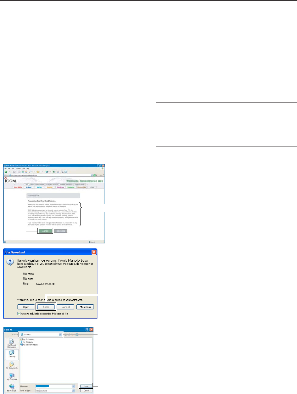
15-3
■Preparation
DFirmware and firm utility
The latest firmware and the firm utility can be down-
loaded from the Icom home page via the INTERNET.
Access the following URL to download the firm utility
and the latest firmware.
http://www.icom.co.jp/world/download/index.htm
For updating from the USB-Memory
When updating the firmware from the USB-Memory,
copy the downloaded firmware data (e.g. 9500xxxx.dat)
to the USB-Memory (in “IC-R9500” folder) using an avail-
able USB port (USB hub may be required; purchased sep-
arately from your PC dealer).
DFile downloading
qAccess the following URL directly.
http://www.icom.co.jp/world/download/index.htm
• No link is available from the top page.
wRead “Regarding this Download Service” carefully,
then click [AGREE].
eClick “IC-R9500” link then click the firmware file link.
rClick [Save] in the displayed File Download dialog.
tSelect the desired location to whichyou want to
save the firmware, then click [Save] in the displayed
File Download dialog.
• File download starts.
yAfter download is completed, extract the file.
• The firmware and the firm utility are compressed in “zip”
format, respectively.
• When updating the receiver using with the USB-Mem-
ory, copy the extracted firmware (e.g. 9500xxxx.dat) to
the USB-Memory IC-R9500 folder.
• The USB-Memory must have been formatted by the IC-
R9500 (p. 11-23).
Select the saving
location
Click
9500xxxx.dat
Click
Click
Read carefully
15
UPDATING THE FIRMWARE
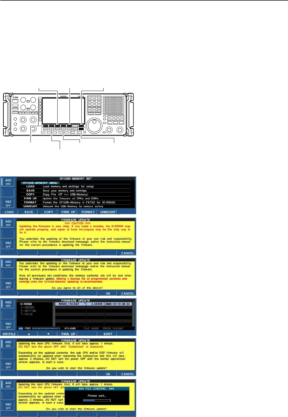
15-4
■Firmware update—USB-Memory
When updating the firmware with the CF card or USB-
Memory, no IP address or subnet mask settings are
necessary.
qCopy the downloaded firmware data into the USB-
Memory (“IC-R9500” folder).
• The USB-Memory must have been formatted by the IC-
R9500.
wInsert the USB-Memory into the USB connector.
ePush [EXIT/SET] several times to close a multi-
function screen, if necessary.
rPush [F-7•SET] to select set mode menu screen.
tPush [F-7•CF/USB] to select CF/USB-Memory set
menu.
yPush and hold [F-3•FIRM UP] for 1 sec.
uRead the displayed precautions carefully.
• Push [F-1•Y] or [F-2•Z] to scroll the text.
• Push [F-7•CANCEL] to cancel firmware updating.
iAfter you read and understand all of the precau-
tions, push [F-6•OK].
• [F-6•OK] appears only following the precautions.
• Push [F-7•CANCEL] to cancel the firmware updating.
oPush [F-2•Y] or [F-3•Z] to select the firmware file,
then push [F-4•FIRM UP].
• Push and hold [F-1•DIR/FILE] for 1 sec. to select the
USB-Memory, if CF card is selected.
!0 Read the displayed precautions carefully.
!1 If you agree, push [F-6•OK] for 1 sec. to start the
firmware update.
• Push [F-7•CANCEL] to cancel firmware updating.
!2 While loading the firmware from the CF memory
card, the dialog at left is displayed.
[EXIT/SET]
[F-2•Z]/[F-2•Y]
[F-3•FIRM UP]/[F-3•Z] [F-6•OK]
[F-1•Y]/[F-1•DIR/FILE]
[F-7•SET]/[F-7•CF/USB]
/[F-7•CANCEL]
[F-4•FIRM UP]
15 UPDATING THE FIRMWARE
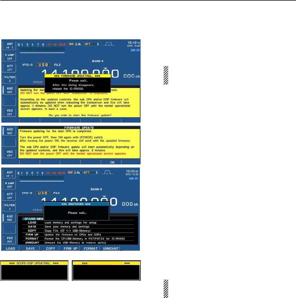
15-5
!3 After firmware loading is completed, the receiver
starts the update automatically and the dialog at left
is displayed.
RWARNING!: NEVER turn the IC-R9500 power
OFF at this stage.
The receiver firmware will be damaged.
!4 When the dialog disappears, the precaution as at
left is displayed.
!5 Read the precaution carefully, and then push
[F-6•OK].
• Return to CF/USB-Memory set menu.
!6 Push [POWER] to turn the IC-R9500 power OFF,
then ON again.
!7 Depending on the status of the update process, ei-
ther of dialogs at left will appears in sequence.
RWARNING!: NEVER turn the IC-R9500 power
OFF at this stage.
The receiver firmware will be corrupted.
!8 After the dialog disappears, the firmware update is
completed and the normal operation screen ap-
pears.
RX-DSP UPDATING...
Please wait for 20sec.
WARNING! NEVER turn power OFF.
Please wait for 45sec.
WARNING! NEVER turn power OFF.
15
UPDATING THE FIRMWARE
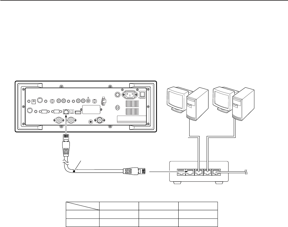
15-6
■Firmware update— PC
DConnections Connect the IC-R9500 and the PC through a LAN
(Local Area Network) as follows.
=××××
*Purchased separately
to WAN
/Internet network
Ethernet cable*
(Patch cable)
to crossover port
• IP address setting example
Hub/Router*
IC-R9500 (192.168.100.13) PC1
(192.168.100.11) PC2
(192.168.100.12)
PC1
192.168.100.11
255.255.255.0
IP address
Subnet mask
PC2
192.168.100.12
255.255.255.0
IC-R9500
192.168.100.13
255.255.255.0
15 UPDATING THE FIRMWARE
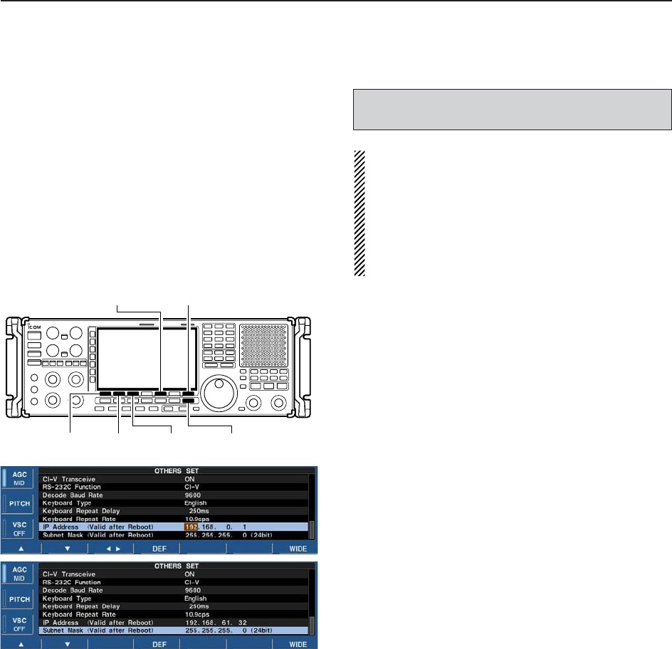
15-7
DIP address setting
IMPORTANT!: A fixed (static) IP address is used for
the IC-R9500.
When you connect the IC-R9500 to a LAN, ask the
network manager about a usable/assignable IP
address and the subnet mask in advance.
NEVER use an IP address that has already been
allocated to another device in the network. If the IP
address is duplicated, the network will crash.
qPush [EXIT/SET] several times to close a multi-
function screen, if necessary.
wPush [F-7•SET] to select set mode menu screen.
ePush [F-5•OTHERS] to select the others set mode.
rPush [F-1•Y]/[F-2•Z] several times to select “IP Ad-
dress.”
tPush [F-3•Ω≈] to select the desired segment then
rotate main dial to set the desired or specified IP ad-
dress.
• “192.168.0.1” is the default setting.
yPush [F-2•Z] to select “Subnet Mask” item.
uRotate main dial to set the desired or specified sub-
net mask.
• “255.255.255.0” is the default setting.
iPush [POWER] to turn the receiver power OFF,
then ON to accept the new IP address and subnet
mask settings.
[EXIT/SET]
[F-2•Z]
[F-1•Y][F-3•Ω≈]
[F-5•OTHERS] [F-7•SET]
When updating the firmware from the USB-Memory,
setting the IP address is not necessary.
15
UPDATING THE FIRMWARE
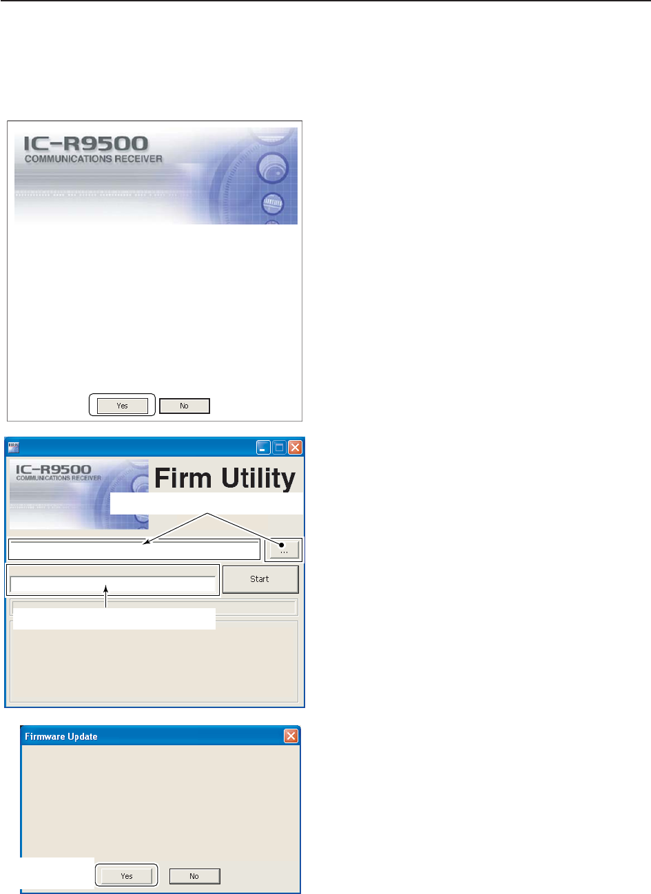
15-8
DUpdating from the PC
qStart up the IC-R9500 Firm Utility.
• The window as at left appears.
wRead the caution in the window carefully.
eClick [Yes] if you agree and to continue the firmware
updating.
rSelect the firmware file with the “dat” extension (e.g.:
9500xxxx.dat).
• Click […], then select the file, as well as the location.
tType the IC-R9500’s IP address into “IC-R9500 IP
Address” text box.
yClick [Start].
uThe window at left appears.
Read the precaution in the window carefully.
iClick [Yes] if you want to start the firmware update.
Updating the main CPU firmware first.
It will take approx. 1 minute.
DO NOT turn the IC-R9500 power OFF until "Completed" dialog is displayed.
Depending on the updated contents, the sub CPU and/or DSP firmware will
automatically be updated when rebooting the IC-R9500 and this will take
approx. 2 minutes. DO NOT turn the IC-R9500 power OFF until the normal
operational screen appears, in such case.
Do you wish to start the firmware update?
Click to start the
firmware update
iR9500
COMMUNICATIONS RECEIVER
IC-R9500 IP Address
Version 1.00
(C) 2006 Icom Inc.
Firmware File Name
Turn the IC-R9500 power ON.
When the normal operational screen appears, set the firmware file name
and IP address, then click [Start] button.
IC-R9500 Firm Utility
Click […] to select the firmware file.
Type the IC-R9500’s IP address here.
Do you agree to all of the above?
iR9500
COMMUNICATIONS RECEIVER
Firm Utility
===CAUTION===
Updating the firmware is very risky. If you make a mistake, the IC-R9500 may
not operate properly, and repair at Icom Inc.(Japan) may be the only way to
fix it.
You undertake the updating of the firmware at you own risk and responsibility,
Please refer to the firmware download homepage and/or the instruction manual
for the correct procedures in updating the firmware.
Also all preciously set conditions, the memory contents, etc will be lost when
making a firmware update.
Making a backup file of programmed contents and settings onto the CF/USB-
Memory before updating is recommended.
Click to
continue
15 UPDATING THE FIRMWARE
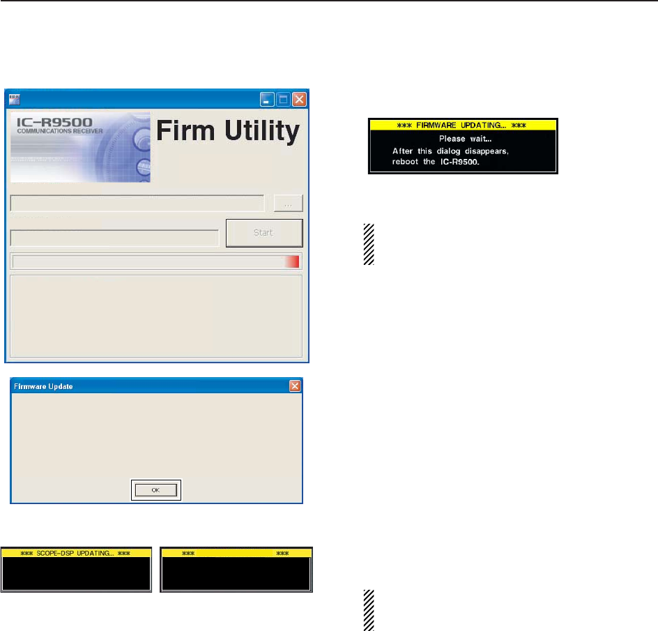
15-9
oThe screen at left is displayed.
• The following dialog appears in the IC-R9500 display.
RWARNING!: NEVER turn the IC-R9500 power
OFF at this stage.
The receiver firmware will be corrupted.
!0 Click [OK] to finish the firmware update.
• The “FIRMWARE UPDATING” dialog as above disap-
pears.
!1 Push [POWER] to turn the IC-R9500 power OFF,
then ON again.
!2 Depending on the status of the update process, ei-
ther of dialogs at left will appear in sequence.
RWARNING!: NEVER turn the IC-R9500 power
OFF at this stage.
The receiver firmware will be corrupted.
!3 After the dialog disappears, the firmware update is
completed and the normal operation screen ap-
pears.
RX-DSP UPDATING...
Please wait for 20sec.
WARNING! NEVER turn power OFF.
Please wait for 45sec.
WARNING! NEVER turn power OFF.
Firmware up dating for the main CPU is completed.
The sub CPU and/or DSP firmware update will start automatically depending on the updated contents,
and this will take approx. 2 minutes.
Turn the IC-R9500 power OFF, then ON again with [POWER] switch.
After turning the power ON, the IC-R9500 will work with the updated firmware.
DO NOT turn the IC-R9500 power OFF until the normal operational screen appears.
Click [OK] to finish the firmware update.
iR9500
COMMUNICATIONS RECEIVER
IC-R9500 IP Address
IC-R9500 IP Address
Firmware File Name
Version 1.00
(C) 2006 Icom Inc.
Firmware File Name
Connecting to the IC-R9500.
Connected to the IC-R9500.
Transfer in progress...
Transfer successful.
Start update.
Please wait a while.
IC-R9500 Firm Utility
15
UPDATING THE FIRMWARE

ABOUT CE
DECLARATION
OF CONFORMITY
D sseldorf 13th Jan.2007
Place and date of issue
Icom (Europe) GmbH
Himmelgeister stra§e 100
D-40225 D sseldorf
Authorized representative name
H. Ikegami
General Manager
Signature
We Icom Inc. Japan
1-1-32, Kamiminami, Hirano-ku
Osaka 547-0003, Japan
Declare on our sole responsibility that this equipment complies with the
essential requirements of the Radio and Telecommunications Terminal
Equipment Directive, 1999/5/EC, and that any applicable Essential Test
Suite measurements have been performed.
Kind of equipment: COMMUNICATIONS RECEIVER
Type-designation: iR9500
Version (where applicable):
This compliance is based on conformity with the following harmonised
standards, specifications or documents:
i) Article 3.1a EN 60950-1 (2001):A11:2004
ii) Article 3.1b EN 301489-1 and EN 301489-15
iii) Article 3.2 EN 301 783-2
iv)v)

Please record the serial number of your IC-R9500 receiver below for future servicing
reference:
Serial Number :
Date of purchase :
Place where purchased :

1-1-32 Kamiminami, Hirano-ku, Osaka 547-0003, Japan
<Intended Country of Use>
■GER ■FRA ■ESP ■SWE
■AUT ■NED ■POR ■DEN
■GBR ■BEL ■ITA ■FIN
■IRL ■LUX ■GRE ■SUI
■NOR
IC-R9500
#03 (France)
<Intended Country of Use>
■GER ■FRA ■ESP ■SWE
■AUT ■NED ■POR ■DEN
■GBR ■BEL ■ITA ■FIN
■IRL ■LUX ■GRE ■SUI
■NOR
IC-R9500
#04 (Europe)
<Intended Country of Use>
■GER ■FRA ■ESP ■SWE
■AUT ■NED ■POR ■DEN
■GBR ■BEL ■ITA ■FIN
■IRL ■LUX ■GRE ■SUI
■NOR
IC-R9500
#05 (United
Kingdom)