ICOM orporated 286900 VHF/UHF Dual Band FM Transceiver User Manual IC P7A
ICOM Incorporated VHF/UHF Dual Band FM Transceiver IC P7A
UserManual.wiki
>
ICOM orporated
>
286900 User Manual
>
Users Manual 1
Contents
1.
Users Manual 1
2.
Users Manual 2
Users Manual 1
Navigation menu
Upload a User Manual
Namespaces
Wiki Guide
HTML
PDF
Info
Views
User Manual
Discussion / Help
Navigation
![iv123456789101112131415■Transmitting.................................................................................... 16■Transmit power selection ............................................................... 16■Dial select step............................................................................... 17■Lock function .................................................................................. 18■[DIAL] function assignment ............................................................ 185REPEATER OPERATION............................................................ 19–23■General........................................................................................... 19■Offset frequency............................................................................. 20■Subaudible tones............................................................................ 21■1750 Hz tone.................................................................................. 22■Auto repeater function .................................................................... 236MEMORY/CALL CHANNELS ..................................................... 24–33■General description ........................................................................ 24■Memory channel programming....................................................... 24■Memory bank setting...................................................................... 25■Memory bank selection .................................................................. 26■Programming memory/bank name ................................................. 27■Selecting display type..................................................................... 28■Copying memory contents.............................................................. 29■Memory clearing............................................................................. 30■Transferring memory contents ....................................................... 31■Erasing/transferring bank contents................................................. 32■Call channel programming ............................................................. 33■Copying call channel contents........................................................ 337SCAN OPERATION .................................................................... 34–41■Scan types...................................................................................... 34■Full/band/programmed scan........................................................... 35■Scan edges programming .............................................................. 36■Memory/bank scan......................................................................... 37■Auto memory write scan................................................................. 38■Skip channel/frequency setting ...................................................... 39■Scan resume condition................................................................... 418PRIORITY WATCH ..................................................................... 42–44■Priority watch types ........................................................................ 42■Priority watch operation.................................................................. 439TONE SQUELCH AND POCKET BEEP .................................... 45–48■Tone/DTCS squelch operation ....................................................... 45■Tone squelch frequency/DTCS code setting .................................. 46■DTCS polarity setting ..................................................................... 47■Tone scan ....................................................................................... 4810 SET MODE ................................................................................. 49–59■General........................................................................................... 49■Set mode items .............................................................................. 5011 OTHER FUNCTIONS ................................................................. 60–64■Weather channel operation ............................................................ 60■Data cloning .................................................................................. 61■Auto power-off function .................................................................. 63■TV channel operation ..................................................................... 63■Partial reset .................................................................................... 64■All reset ......................................................................................... 6412 FREQUENCY TABLE ................................................................. 65–72■TV channels ................................................................................... 65■VHF marine channels..................................................................... 68■Weather channels .......................................................................... 68■Other communications in the USA ................................................. 69■Other communications—other countries ........................................ 7113 MAINTENANCE ......................................................................... 73–74■Troubleshooting.............................................................................. 73■Optional CP-21LR fuse replacement.............................................. 7414 SPECIFICATIONS ...................................................................... 75–76■Transceiver..................................................................................... 75■Battery pack (BP-243).................................................................... 76■Battery charger (BC-164) ............................................................... 7615 OPTIONS .................................................................................... 77–79■Options........................................................................................... 7716 POCKET GUIDE ......................................................................... 80–811617](https://usermanual.wiki/ICOM-orporated/286900.Users-Manual-1/User-Guide-599077-Page-5.png)
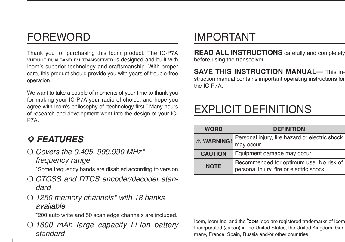
![IIQUICK REFERENCE GUIDEDCharging the batteryRRWARNING!:NEVER charge any other than the specified battery pack. DCharging descriptionqPlug the AC adapter into an AC outlet; or the optional CP-21LR into a cigarette lighter socket.wInsert the adapter plug into [12~16V DC INPUT] of the BC-164 BATTERY CHARGER.eInstall the BP-243 BATTERY PACK(See left page) to thetransceiverrBe sure to turn OFF the transceiver, then charge the bat-tery with transceiver.•Takes approximately 3 hours for fully charge with the suppliedBP-243 battery pack.•Charging indicator of BC-164 lights or blinks as follows.*It may be charging outside of the specified temperature range: +5˚C to+35˚C (+41˚F to +95˚F). Restore the specified temperature range andreinsert the transceiver.NOTE: The transceiver has battery indicator to show thefollowing information.•No indicator appears when the installed battery pack hasample capacity.•“” (battery indicator) appears when the battery packis nearing exhaustion.•“” blinks when the battery pack must be charged.•“” and “LOW” indicator appear just before the batterypack is completely discharged and display turns OFF.BC-164ChargingindicatorTransceiver to [12~16V DC INPUT] jackAC adapterto cigarette lighter socketto AC outletSCANSETS.MWOptional CP-21LRCigarette lighter cable with noise filterQuick reference guideCharging indicator status Charging statusLights orange ChargingLights green Charging is completedBlinking red Charging error*](https://usermanual.wiki/ICOM-orporated/286900.Users-Manual-1/User-Guide-599077-Page-7.png)
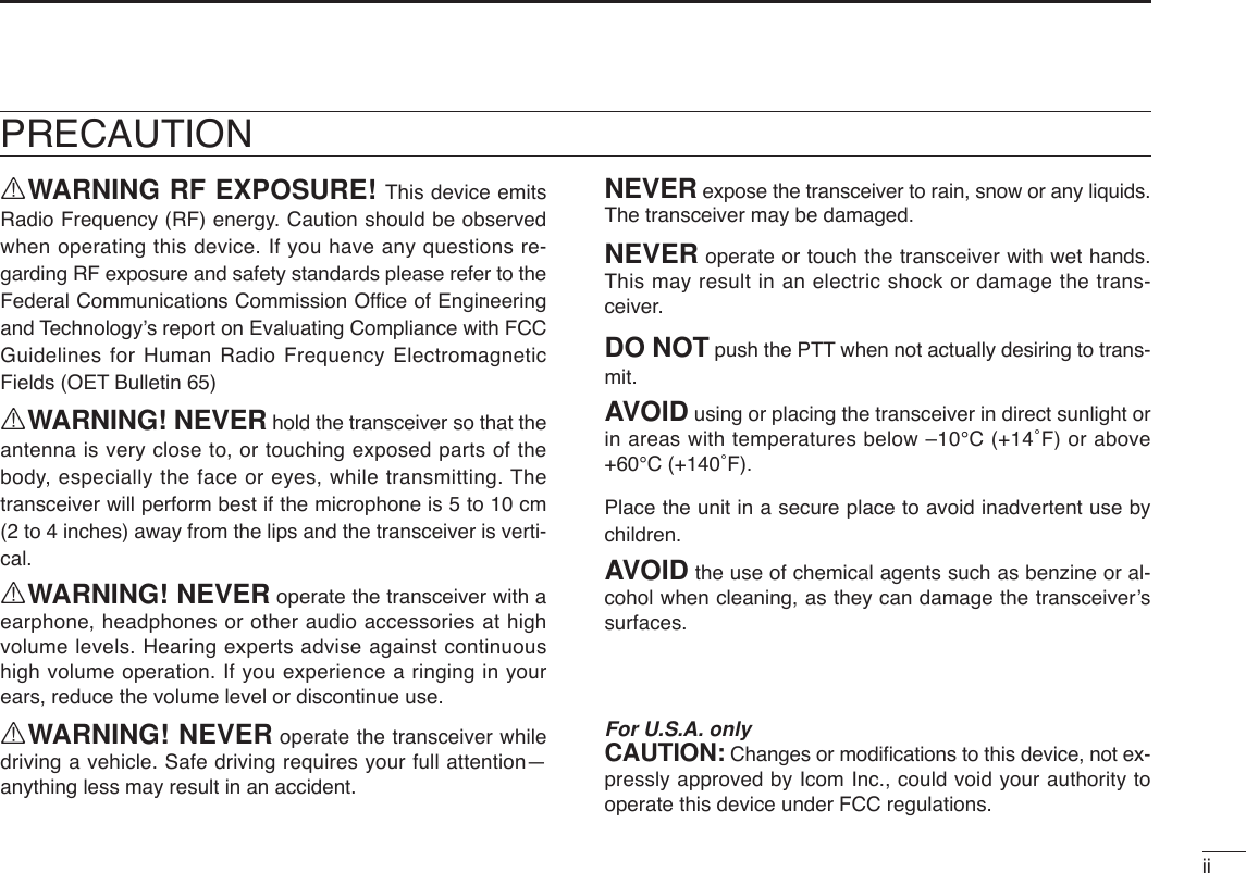
![IIIQUICK REFERENCE GUIDE■Your first contactNow that you have your IC-P7A ready, you are probably ex-cited to get on the air. We would like to take you through afew basic steps to make your first experience “On The Air” en-joyable. DAbout default settingsThe [DIAL] control function can be exchanged with the[YY]/[ZZ]key functions by pushing and holding [FUNC] thenpush [YY]or [ZZ]. However, in this QUICK REFERENCEGUIDE, the factory default setting ([DIAL] sets operating fre-quency) is used to simplify the instructions.DBasic operation1. Turning ON the transceiver➥Push and hold [PWR] for 1sec. to turn the power ON.•Opening indication passesthrough, then frequency indica-tion appears.The opening indication canbe skipped. While pushingand holding [FUNC], pushand hold [PWR] for 1 sec. toshortcut the opening indica-tion.2. Adjusting audio level➥Push [YY]/[ZZ]to set the desired audio level.3. Adjusting squelch level➥While pushing and holding [SQL] (ATT•SET), rotate [DIAL]to set the squelch level.SCANSETS.MW[DIAL][SQL]SCANSETS.MW[Y]/[Z]SCANSETS.MW[PWR]](https://usermanual.wiki/ICOM-orporated/286900.Users-Manual-1/User-Guide-599077-Page-8.png)
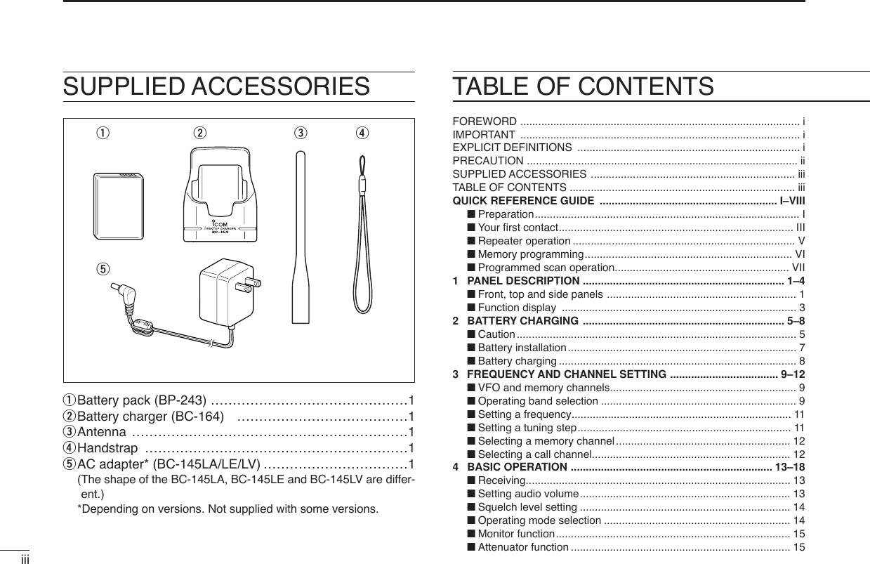
![IVQUICK REFERENCE GUIDE4. Tune the desired frequencyThe tuning dial will allow you to dial in the frequency you wantto use. Pages 11 and 17 will instruct you on how to set thetuning step size.qPush [BAND] (TS•LOCK)sev-eral times to select the de-sired frequency band.•While pushing and holding[BAND] (TS•LOCK), rotating[DIAL] also selects frequencyband.wRotate [DIAL] to set the de-sired frequency.•While pushing and holding[FUNC], rotate [DIAL] to selectfrequency in 1 MHz steps.5. Operating mode selection➥While pushing and holding[FUNC], push [CALL](MODE•SCAN)several times toselect the desired operatingmode.•FM, WFM and AM modes areselectable.6. Transmit and receive➥Push and hold [PTT] to trans-mit then speak into the micro-phone; release to receive.•Transmission is available on the144 MHz/440 MHz (FM mode)amateur bands only.SCANSETS.MWMicrophone[PTT]SCANSETS.MW[CALL][FUNC]SCANSETS.MW[FUNC][BAND][DIAL]Quick reference guide](https://usermanual.wiki/ICOM-orporated/286900.Users-Manual-1/User-Guide-599077-Page-9.png)
![VQUICK REFERENCE GUIDE■Repeater operation1. Setting duplexqWhile pushing and holding[FUNC], push and hold [SQL](ATT•SET)for 1 sec. to enter setmode.wRotate [DIAL] to select “DUP.”eWhile pushing and holding[FUNC], rotate [DIAL] to selectminus duplex or plus duplex.•The USA/KOREA versions havean auto repeater function, there-fore setting duplex is not re-quired.rPush [SQL] (ATT•SET) to exit set mode.2. Repeater toneqWhile pushing and holding[FUNC], push and hold [SQL](ATT•SET)for 1 sec. to enter setmode.wRotate [DIAL] to select“T/TSQL.”eWhile pushing and holding[FUNC], rotate [DIAL] to selectthe repeater tone activation.rPush [SQL] (ATT•SET) to exit set mode.ATTDTCSTSQLWFMAM -DUPLOWVOL PRIO P S KI PMR519ATTDTCSTSQLWFMAM -DUPLOWVOL PRIO P S KI PMR519ATTDTCSTSQLWFMAM -DUPLOWVOL PRIO P S KI PMR519SCANSETS.MW[SQL][FUNC][DIAL]ATTDTCST SQLWFMAM -DUPLOWVOL PRIO P SK IPMR519ATTDTCSTSQLWFMAM -DUPLOWVOL PRIO P S KI PMR519ATTDTCSTSQLWFMAM -DUPLOWVOL PRIO P S KI PMR519SCANSETS.MW[SQL][FUNC][DIAL]](https://usermanual.wiki/ICOM-orporated/286900.Users-Manual-1/User-Guide-599077-Page-10.png)
![VIQUICK REFERENCE GUIDEQuick reference guide■Memory programmingThe IC-P7A has a total of 1250 memory channels (including200 auto write channels and 50 scan edges) for storing oftenused operating frequency, mode, etc.1. Setting frequencyIn VFO mode, set the desired receive frequency mode.•When “ ” indicator is displayed, push [V/M] (SKIP•S.MW)to selectthe VFO mode.2. Selecting a memory channelPush [V/M] (SKIP•S.MW)for 1 sec. toenter select memory write mode(1short and 1 long beep sound),then rotate [DIAL] to select the de-sired memory channel.•“ ” indicator and memory channelnumber blink.•To cancel and exit select memory write mode, push [V/M](SKIP•S.MW)momentarily.3. Writing a memory channelPush and hold [V/M] (SKIP•S.MW)for 1 sec. until 3 beepssound.•Memory channel number automatically increases when continuingto push [V/M] (SKIP•S.MW)after programming.SCANSETS.MW[V/M]ATTDTCSTSQLWFMAM -DUPLOWVOL PRIO P S KI PMR519SCANSETS.MW[DIAL][V/M]](https://usermanual.wiki/ICOM-orporated/286900.Users-Manual-1/User-Guide-599077-Page-11.png)
![VIIQUICK REFERENCE GUIDE■Programmed scan operation50 channels of memories in 25 pairs are used to specifyscanning ranges for programmed scan operation. The pro-grammed scan scans between “xxA” and “xxb” (xx=00 to 24)channels. Therefore, before operating the programmed scan,different frequencies must be programmed into the “A” and“b” channels.DDProgramming scan edgesAstart and stop frequency must be programmed into a pairof "xxA" or "xxb" channels. 1. Setting frequencyIn VFO mode, set the desired operating frequency and mode.•When “ ” indicator is displayed, push [V/M] (SKIP•S.MW)to selectthe VFO mode.2. Selecting a scan edge channel “A”Push and hold [V/M] (SKIP•S.MW)for 1sec. to enter select memory writemode (1short and 1 long beepsound), then rotate [DIAL] to selectthe desired scan edge channel “A.”•“ ” indicator and scan edge channelnumber blink.3. Writing a memory channelPush and hold [V/M] (SKIP•S.MW)for 1 sec. until 3 beepssound.•Scan edge channel “b” is automatically selected when continuing topush [V/M] (SKIP•S.MW)after programming.•After programming is completed, the display returns to VFO indica-tion.4. Selecting a scan edge channel “b”Push and hold [V/M] (SKIP•S.MW)for 1sec., then rotate [DIAL] to select thedesired scan edge channel “b.”•“ ” indicator and scan edge channelnumber blink.•When the scan edge channel “b” is already selected at step 3, con-tinuing to push [V/M] (SKIP•S.MW)after programming, skip this step.5. Writing a memory channelPush and hold [V/M] (SKIP•S.MW)for 1 sec. until 3 beepssound.•The next scan edge channel “A” is automatically selected when con-tinuing to push [V/M] (SKIP•S.MW)after programming.•After programming is completed, the display returns to VFO indica-tion.ATTDTCSTSQLWFMAM -DUPLOWVOL PRIO P S KI PMR519ATTDTCSTSQLWFMAM -DUPLOWVOL PRIO P S KI PMR519](https://usermanual.wiki/ICOM-orporated/286900.Users-Manual-1/User-Guide-599077-Page-12.png)
![VIIIQUICK REFERENCE GUIDEDDStarting scan 1. Select VFO mode.Push [V/M] (SKIP•S.MW)to select the VFO mode for full, bandand programmed scan operation.•Select memory mode by pushing [V/M] (SKIP•S.MW)again for mem-ory or bank scan.2. Selecting a scanning typePush and hold [CALL] (MODE•SCAN)for 1 sec., then rotate[DIAL] to select the desired scanning type.•Available scan types when VFO mode is selected; “ALL” for fullscan; “BAND” for the selected band; one of “PROGxx” (xx=0 to 24)for programmed scan.•Available scan types when memory mode is selected; “M ALL” for allmemory scan “B ALL” for all bank scan, “B LINK” for bank link scan,“BANK” for the selected bank scan.3. Starting scanPush [CALL] (MODE•SCAN)to start the scan.•Rotate [DIAL] to change the scanning direction.4. Cancelling scanPush [CALL] (MODE•SCAN)again to stop scan.✔For your informationThe memory channel number you program the scan edgesinto correlate “PROGxx” as follows:00A/00b: Select “PROG 00” to scan between frequenciesprogrammed in 00A and 00b channels.01A/01b: Select “PROG 01” to scan between frequenciesprogrammed in 01A and 01b channels.••••24A/24b: Select “PROG 24” to scan between frequenciesprogrammed in 24A and 24b channels.ATTDTCSTSQLWFMAM -DUPLOWVOL PRIO P S KI PMR519ATTDTCSTSQLWFMAM -DUPLOWVOL PRIO P S KI PMR519ATTDTCST SQLWFMAM -DUPLOWVOL PRIO P S KI PMR519ATTDTCST SQLWFMAM -DUPLOWVOL PRIO P S KI PMR519• Programmed scan• Full/Band scan• Bank scan• All memory/All bank/ Bank link scanSCANSETS.MW[DIAL][CALL]• Full scan• Scan type indication examples• Programmed scan• Band scanQuick reference guide](https://usermanual.wiki/ICOM-orporated/286900.Users-Manual-1/User-Guide-599077-Page-13.png)
![■Front, top and side panelsqANTENNA CONNECTOR (p. I)Connects to the supplied antenna.•An optional AD-92SMA adapter (p. 77) is available for connect-ing an antenna with a BNC connector.wEXTERNAL SPEAKER/MICROPHONE JACK [MIC/SP]Connect an optional speaker-microphone or headset viaan optional OPC-782 PLUG ADAPTOR CABLE, if desired.The internal microphone and speaker will not functionwhen the OPC-782 is connected. (See p. 77 for a list ofavailable options.)ePTT SWITCH [PTT] (p. 16)➥Push and hold to transmit, release to receive.➥While pushing and holding [FUNC], push to toggle thetransmit output power between High and Low.rFUNCTION KEY [FUNC]Push and hold this key for access to secondary functions.tUP/DOWN KEYS [YY]/[ZZ]➥Adjusts audio volume level.* (p. 13)➥While pushing and holding [FUNC], push either key toexchange [DIAL] and [YY]/[ZZ]function. (p. 18)SCANS.MWSETFunction display (pgs 3, 4)SpeakerMicrophone!1!0!2tryuiewqo1PANEL DESCRIPTION1*The function of [DIAL] and [YY]/[ZZ]can be exchanged. See page18 for details.](https://usermanual.wiki/ICOM-orporated/286900.Users-Manual-1/User-Guide-599077-Page-14.png)
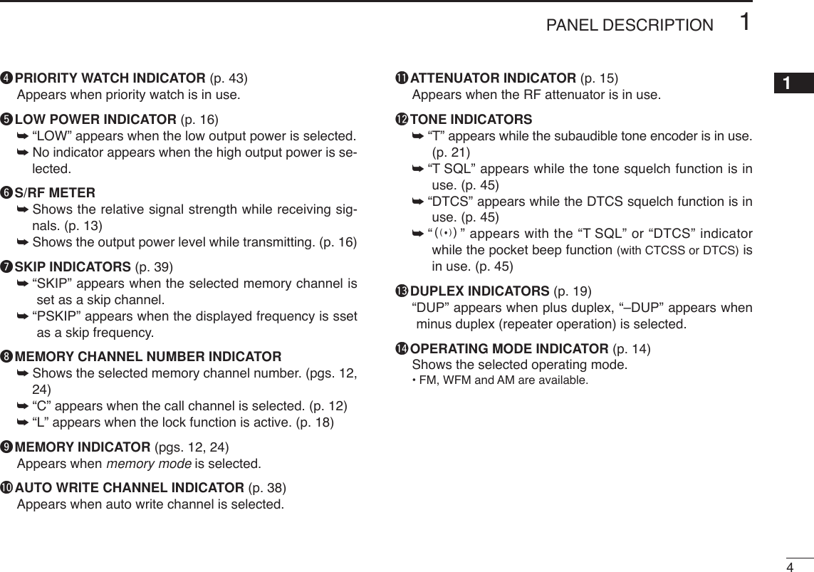
![21PANEL DESCRIPTION1yCALL•MODE•SCAN KEY [CALL] (MODE•SCAN)➥Push momentarily to select the call channel. (p. 12)➥Push and hold for 1 sec. to enter the scan type selectioncondition, push again to start a scan. (p. 35)➥While pushing and holding [FUNC], push momentarilyto select the operating mode. (p. 14)➥While pushing and holding [FUNC], push and hold for1 sec. to start a tone scan. (p. 48)uVFO/MEMORY•MEMORY WRITE KEY [V/M] (SKIP•S.MW)➥Push momentarily to toggle between VFO and memorymode. (p. 9)➥Push and hold for 1 sec. to enter select memory writemode. (p. 24)➥While pushing and holding [FUNC], push momentarilyto select scan skip condition. (p. 40)➥During VFO scan, pushing and holding [FUNC], pushand hold for 1 sec. to store into highest blank memorychannel as PSKIP channel (p. 40)iSQUELCH•ATTENUATOR•SET KEY [SQL] (ATT•SET) ➥Push and hold to open the squelch temporarily andmonitor the operating frequency. (p. 15)➥While pushing and holding this key, rotate [DIAL]* to ad-just the squelch level. (p. 14)➥While pushing and holding [FUNC], push and hold for1 sec. to enter set mode. (p. 49)oPOWER KEY [PWR]Push and hold for 1 sec. to turn the transceiver power ONand OFF. !0BAND•TUNING STEP•LOCK KEY [BAND] (TS•LOCK)➥Push to select the operating frequency band. (p. 9)➥While pushing and holding [FUNC], push momentarilyto enter tuning step set mode. (p. 11)➥While pushing and holding [FUNC], push and hold for1 sec. to toggle the lock function ON and OFF. (p. 18)!1TX RX INDICATOR [TX/RX] (pgs. 13, 16)Lights green while receiving a signal or when the squelchis open; lights red while transmitting.!2CONTROL DIAL [DIAL]➥Rotate to select the operating frequency.* (p. 11)➥While scanning, changes the scanning direction.*(p. 35)➥While pushing and holding [SQL] (ATT•SET), sets thesquelch level.* (p. 14)➥While pushing and holding [FUNC], changes the oper-ating frequency in 100 kHz, 1 MHz or 10 MHz incre-ments in VFO mode.* (p. 11)➥While pushing and holding [FUNC], changes the mem-ory channel in 10 channels steps in memory mode.*(p. 12)➥While pushing and holding [BAND] (TS•LOCK), selectsthe operating band in VFO mode.* (p. 9)➥While pushing and holding [BAND] (TS•LOCK), selectsthe programmed bank or auto memory write channel inmemory mode.* (p. 9)](https://usermanual.wiki/ICOM-orporated/286900.Users-Manual-1/User-Guide-599077-Page-15.png)
![31PANEL DESCRIPTIONqFREQUENCY READOUT Displays a variety of information, such as an operating fre-quency, set mode contents, memory names.•The smaller “75,” “50” and “25” on the right of the readout indi-cate 0.75, 0.5 and 0.25 kHz, respectively.•The decimal point blinks during scan.wDIAL/VOLUME EXCHANGE INDICATOR (p. 18)Appears when the function of [DIAL] and [YY]/[ZZ]are ex-changed.eBATTERY INDICATOR ➥No indicator appears when the installed battery packhas ample capacity.➥“” (battery indicator) appears when the batterypack is nearing exhaustion.➥“” blinks when the battery pack must be charged.➥“” and “LOW” indicator appear just before the bat-tery pack is completely discharged and display turnsOFF. ATTDTCST SQLWFMAM -DUPLOWVOL PRIO P SKIPMR519qwertyuo!4!0!3 !2!1i■Function display](https://usermanual.wiki/ICOM-orporated/286900.Users-Manual-1/User-Guide-599077-Page-16.png)
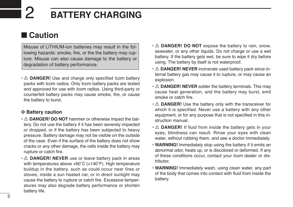
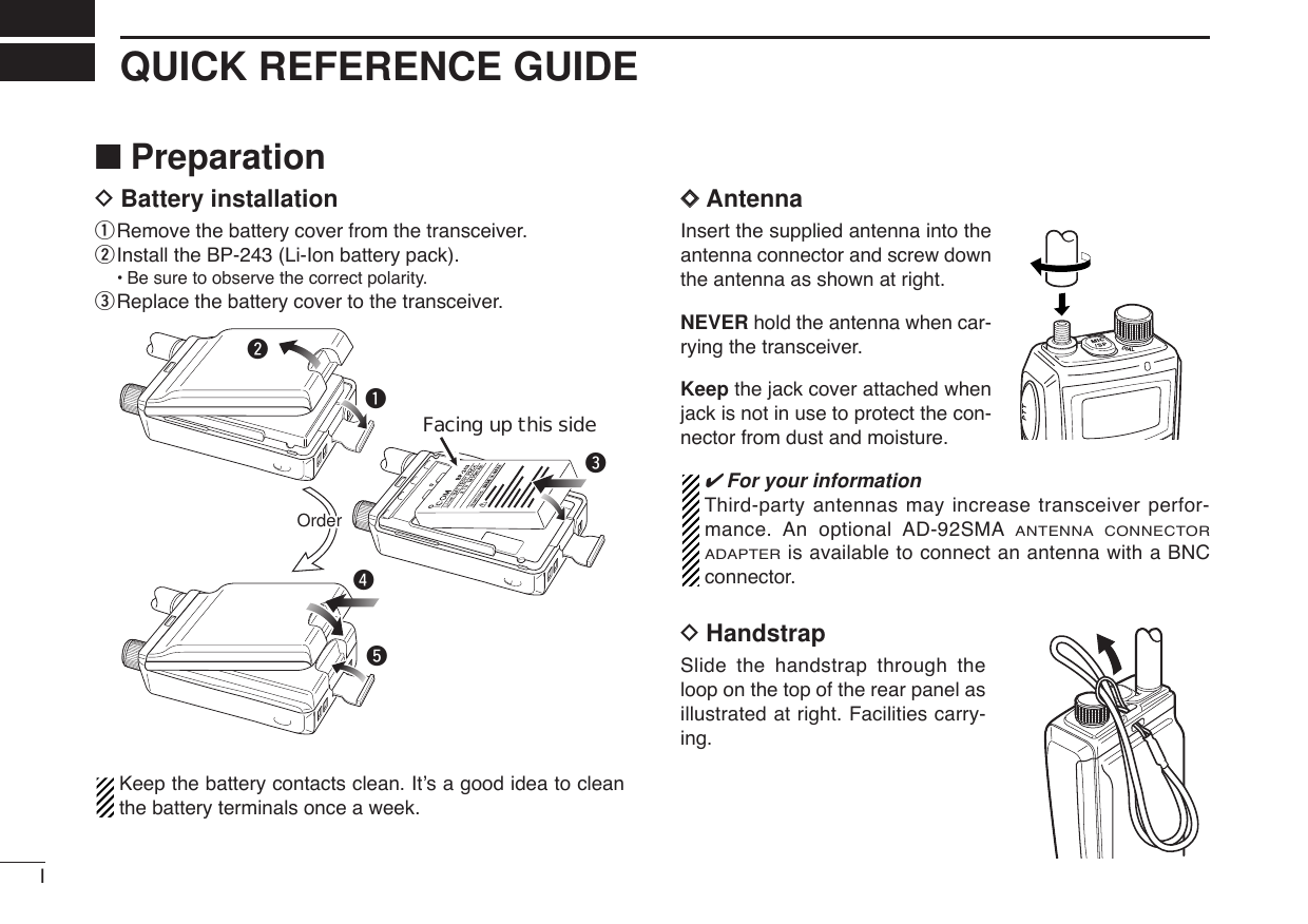
![72BATTERY CHARGING■Battery installationBefore installing, or replacing the battery pack, be sure to turnOFF the transceiver. If it’s ON, push and hold [PWR] for 1sec. to turn the power OFF.qRemove the battery cover from the transceiver.wInstall the BP-243 (Li-Ion battery pack).•Be sure to observe the correct polarity.eReplace the battery cover to the transceiver.Keep the battery contacts clean to avoid rust or poor con-tact. It’s a good idea to clean the battery terminals once aweek.rteFacing up this sidewq](https://usermanual.wiki/ICOM-orporated/286900.Users-Manual-1/User-Guide-599077-Page-20.png)
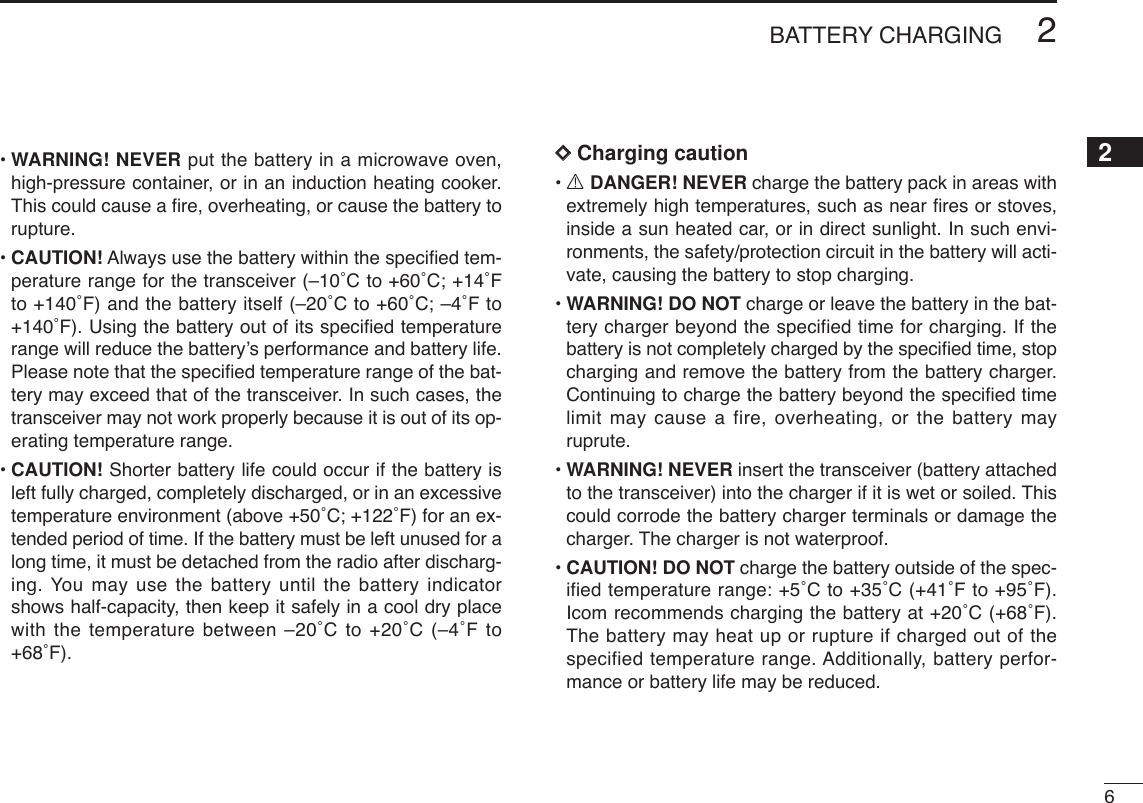
![82BATTERY CHARGING2■Battery chargingDCharging connections•Charging periods: Approx. 3 hoursDCharging descriptionqPlug the AC adapter into an AC outlet; or the optional CP-21LR into a cigarette lighter socket.wInsert the adapter plug into [12~16V DC INPUT] of the BC-164 BATTERY CHARGER.eInstall the BP-243 BATTERY PACK(See left page) in thetransceiverrBe sure to turn OFF the transceiver, then charge the bat-tery with transceiver.•Takes approximately 3 hours to fully charge with the supplied BP-243 battery pack.CAUTION: BE SURE to disconnect the CP-21LR from thecigarette lighter socket when charging is finished, because,a slight current still follows in the CP-21LR and the vehi-cle’s battery will become will be drained.Charging indicator of BC -164Orange (lights) : During charging.Green (lights) : When the battery pack is charged completely.Red (blinking) : Thecharger may be outside of the specifiedtemperature range: +5˚C to +35˚C (+41˚F to+95˚F). Restore the specified temperaturerange and reinsert the transceiver or contactyour dealer.BC-164ChargingindicatorTransceiver to [12~16V DC INPUT] jackAC adapterto cigarette lighter socketto AC outletSCANSETS.MWOptional CP-21LRCigarette lighter cable with noise filter](https://usermanual.wiki/ICOM-orporated/286900.Users-Manual-1/User-Guide-599077-Page-21.png)
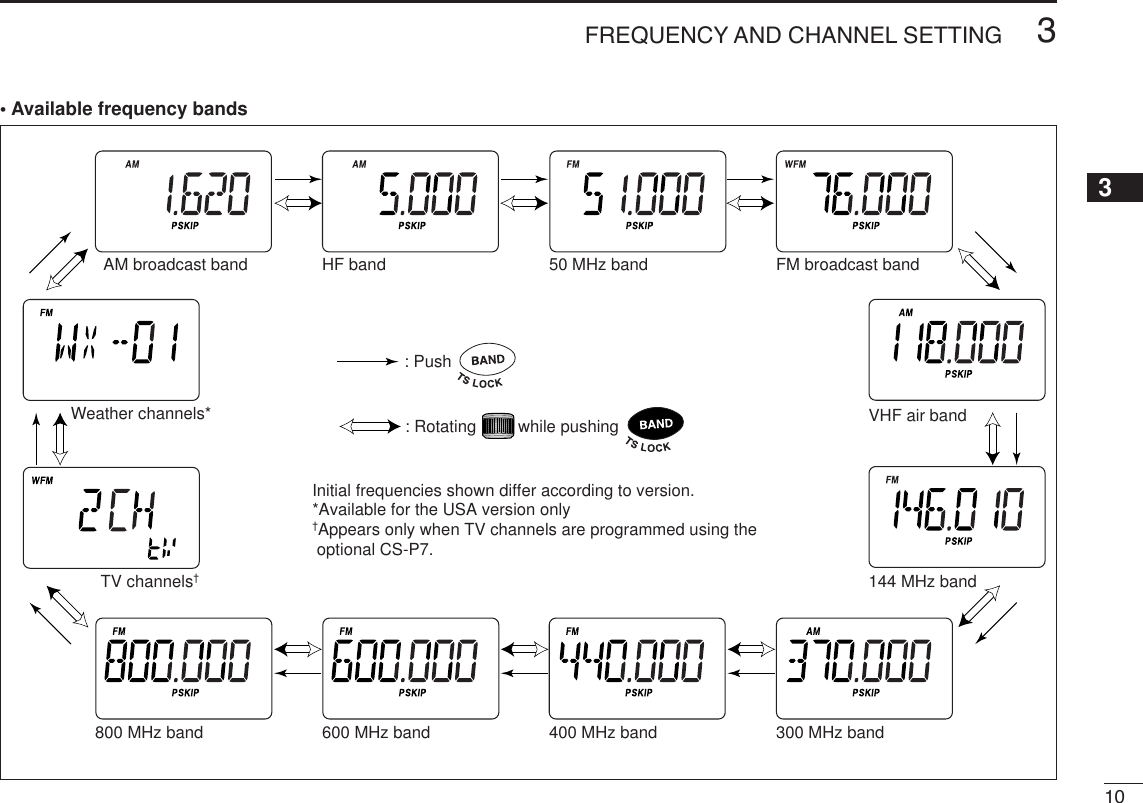
![9FREQUENCY AND CHANNEL SETTING3■VFO and memory channelsThe IC-P7A has two primary operating modes: VFO modeand memory mode.VFO mode is used for setting the desired frequency withinthe frequency coverage.➥Push [V/M] (SKIP•S.MW)to select VFO mode.Memory mode is used for operating from memory channelswhich have programmed frequencies.➥Push [V/M] (SKIP•S.MW)to select memory mode.•See p. 24 for memory programming details.What is VFO?VFO is an abbreviation of Variable Frequency Oscillator. Fre-quencies for receiving or transmitting are selected and con-trolled by the VFO.■Operating band selectionThe transceiver can receive the AM broadcast, HF band,50 MHz, FM broadcast, VHF air, 144 MHz, 300 MHz,400 MHz, 600 MHz, *800 MHz, television channels or†Weather channels.Available frequency bands are differ depending on version.See the specification for details. (p. 75)*Some frequency ranges are inhibited for the USA versiondue to local regulation.†Available for the USA version only.➥Push [BAND] (TS•LOCK)several times to select the desiredfrequency band.•When memory mode is selected, push [V/M] (SKIP•S.MW)to se-lect VFO mode first.➥While pushing and holding [BAND] (TS•LOCK), rotating[DIAL] also selects frequency band.SCANS.MWSET[DIAL][DIAL]PushDual operationPush and hold +SCANSETS.MWATTDTCSTSQLWFMAM -DUPLOWVOL PRIO P S KI PMR519ATTDTCSTSQLWFMAM -DUPLOWVOL PRIO P S KI PMR519“ ” and memory channel number appear.• VFO mode indication• Memory mode indicationS.MW](https://usermanual.wiki/ICOM-orporated/286900.Users-Manual-1/User-Guide-599077-Page-22.png)
![■Setting a frequencyqPush [V/M] (SKIP•S.MW)to select VFO mode, if necessary.wSelect the desired frequency band with [BAND] (TS•LOCK).•Or, while pushing and holding [BAND] (TS•LOCK), rotate [DIAL]to select the desired frequency band.eRotate [DIAL] to select the desired frequency.•The frequency changes according to the preset tuning steps.See the section at right for setting the tuning step.•While pushing and holding [FUNC], rotate [DIAL] to change thefrequency in 1 MHz steps (default).The 1 MHz tuning step (dial select step) can be set to100 kHz, 1 MHz or 10 MHz tuning steps in set mode. Seep. 17 for details.■Setting a tuning stepThe tuning step can be selected for each frequency band.The following tuning steps are available for the IC-P7A.•5.0 kHz* • 6.25 kHz* • 8.33 kHz†•9.0 kHz‡•10.0 kHz•12.5 kHz • 15.0 kHz • 20.0 kHz • 25.0 kHz • 30.0 kHz•50.0 kHz • 100.0 kHz • 200.0 kHz* Appears for below the 500 MHz bands only. †Appears for the VHF air band only.‡Appears for the AM broadcast band only.DDTuning step selectionqPush [V/M] (SKIP•S.MW)toselect VFO mode, if neces-sary.wPush [BAND] (TS•LOCK)several times to select thedesired frequency band.•Or, while pushing and hold-ing [BAND] (TS•LOCK), rotate[DIAL] to select the desiredfrequency band.eWhile pushing and holding[FUNC], push [BAND](TS•LOCK)momentarily toenter tuning step set mode.rRotate [DIAL] to select thedesired tuning step.tPush [BAND] (TS•LOCK)toreturn to VFO mode.SCANSETS.MWATTDTCSTSQLWFMAM -DUPLOWVOL PRIO P S KI PMR519[DIAL]5 kHz tuning stepSCANSETS.MWATTDTCSTSQLWFMAM -DUPLOWVOL PRIO P S KI PMR519ATTDTCSTSQLWFMAM -DUPLOWVOL PRIO P S KI PMR519[DIAL] changes the fre-quency according to the selected tuning step.While pushing [FUNC], [DIAL] changes the frequen-cy in 1 MHz steps (default).[DIAL]113FREQUENCY AND CHANNEL SETTING](https://usermanual.wiki/ICOM-orporated/286900.Users-Manual-1/User-Guide-599077-Page-24.png)
![123FREQUENCY AND CHANNEL SETTING 3■Selecting a memory channelqPush [V/M] (SKIP•S.MW)momentarily to select memorymode.•“ ” appears when a memory channel is selected.wRotate [DIAL] to select the desired memory channel.•Only programmed memory channels can be selected.•While pushing and holding [FUNC], rotate [DIAL] to select amemory channel in 10 channel steps, blank channels can be se-lected in this case.■Selecting a call channelqPush [CALL] (MODE•SCAN)momentarily to select a callchannel.wRotate [DIAL] to select the desired call channel.ePush [CALL] (MODE•SCAN)or [V/M] (SKIP•S.MW) momen-tarily to return to the previously selected mode.ATTDTCSTSQLWFMAM -DUPLOWVOL PRIO P S KI PMR519ATTDTCSTSQLWFMAM -DUPLOWVOL PRIO P S KI PMR519144 MHz band 440 MHz band• Call channel example (depends on version)SCANS.MWSETSCAN[DIAL]SCANS.MWSETATTDTCSTSQLWFMAM -DUPLOWVOL PRIO P S KI PMR519[DIAL][DIAL] changes the mem-ory channel.S.MWPush Push and hold Dual operation](https://usermanual.wiki/ICOM-orporated/286900.Users-Manual-1/User-Guide-599077-Page-25.png)
![■ReceivingMake sure charged battery pack (BP-243) is installed (p. 7).qPush and hold [PWR] for 1 sec. to turn power ON.wPush [YY]or [ZZ]to set the desired audio level. •The frequency display shows the volume level while setting. Seethe section at right for details.eSet the receiving frequency. (p. 11)rSet the squelch level. (p. 14)•While pushing and holding [SQL] (ATT•SET), rotate [DIAL].•The first click of [DIAL] indicates the current squelch level.•“LEVEL 1” is loose squelch (for weak signals) and “LEVEL 9” istight squelch (for strong signals).•“AUTO” indicates automatic level adjustment by a noise pulsecounting system.•Push and hold [SQL] (ATT•SET)to open the squelch manually.tWhen a signal is received:•TX/RX indicator lights green.•Squelch opens and audio is emitted.•The S/RF meter shows the relative signal strength level.■Setting audio volumeThe audio level can be adjusted to one of 40 levels.➥Push [YY]or [ZZ]to adjust the audio level.•If squelch is closed, push and hold [SQL] (ATT•SET)to verify theaudio level.•Pushing and holding either key changes the audio level continu-ously.•The display shows the volume level while setting.SCANS.MWSETINDICATION AUDIO LEVELMinimum setting(no audio)Muximum settingInitial settingSCANSETS.MWq [PWR]e Set frequencyr Set squelch levelw Set audio level e Select bandr Push for setting the squelch (Push to monitor)13BASIC OPERATION4](https://usermanual.wiki/ICOM-orporated/286900.Users-Manual-1/User-Guide-599077-Page-26.png)
![144BASIC OPERATION4■Squelch level settingThe squelch circuit mutes the received audio signal depend-ing on the signal strength. The transceiver has 9 squelch lev-els, a continuously open setting and an automatic squelchsetting.➥While pushing and holding [SQL] (ATT•SET), rotate [DIAL]to select the squelch level.•“LEVEL 1” is loose squelch (for weak signals) and “LEVEL 9” istight squelch (for strong signals).•“AUTO” indicates automatic level adjustment by a noise pulsecounting system.•“OPEN” indicates continuously open setting.■Operating mode selectionOperating modes are determined by the modulation of theradio signals. The transceiver has 3 operating modes: FM,AM and WFM modes. The mode selection is stored indepen-dently in each band and memory channels.Typically, AM mode is used for the AM broadcast stations(0.495–1.620 MHz) and air band (118–135.995 MHz), andWFM is used for FM broadcast stations (76–107.9 MHz).WFM mode cannot be selected below 30 MHz bands for allversions (and above 850 MHz bands for USA version).➥While pushing and holding [FUNC], push [CALL](MODE•SCAN)several times to select the desired operatingmode.SCANS.MWATTDTCSTSQLWFMAM -DUPLOWVOL PRIO P S KI PMR519ATTDTCSTSQLWFMAM -DUPLOWVOL PRIO P S KI PMR519ATTDTCSTSQLWFMAM -DUPLOWVOL PRIO P SKIPMR519FM modeAM modeWFM modeSCANSETSCANS.MWSETATTDTCSTSQLWFMAM -DUPLOWVOL PRIO P S KI PMR519ATTDTCSTSQLWFMAM -DUPLOWVOL PRIO P S KI PMR519[DIAL]Automatic squelchMaximum levelSETPush Push and hold Dual operation](https://usermanual.wiki/ICOM-orporated/286900.Users-Manual-1/User-Guide-599077-Page-27.png)
![■Monitor functionThis function is used to listen to weak signals without disturb-ing the squelch setting or to open the squelch manually evenwhen mute functions such as the tone squelch are in use.➥Push and hold [SQL] (ATT•SET)to monitor the operatingfrequency.The [SQL] (ATT•SET)key can be set to ‘sticky’ operation inexpanded set mode. See page 56 for details.■Attenuator functionThe attenuator prevents distortion of a desired signal whenvery strong RF signals are near the desired frequency orwhen very strong electric fields, such as from a broadcastingstation, are present at your location.➥While pushing and holding [FUNC], push [SQL] (ATT•SET)momentarily to toggle the attenuator function ON and OFF.•“ATT” appears when the attenuator functions is in use.SCANS.MWSETATTDTCSTSQLWFMAM -DUPLOWVOL PRIO P SKIPMR519ATTSETAppearsSCANS.MWSETATTDTCSTSQLWFMAM -DUPLOWVOL PRIO P S KI PMR519The 1st segment blinksSET154BASIC OPERATIONPush Push and hold Dual operation](https://usermanual.wiki/ICOM-orporated/286900.Users-Manual-1/User-Guide-599077-Page-28.png)
![164BASIC OPERATION4■TransmittingNOTE: To prevent interference, listen on the channel be-fore transmitting by pushing and holding [SQL] (ATT•SET).qSet the operating frequency. (pgs. 9, 11)•Transmission is available on the 144 MHz/440 MHz (FM mode)amateur bands only.•Select output power if desired. See the section at right for details.wPush and hold [PTT] to transmit.•TX/RX indicator lights red.•S/RF meter shows the output power level.eSpeak into the microphone using your normal voice level.•DO NOT hold the transceiver too close to your mouth or speaktoo loudly. This may distort the signal.rRelease [PTT] to return to receive.■Transmit power selectionThe transceiver has two output power levels to suit your op-erating requirements. Low output power during short-rangecommunications may reduce the possibility of interference toother stations and will reduce current consumption.➥While pushing and holding [FUNC], push [PTT] to togglethe transmit output power between High and Low.•“LOW” appears when the low power is selected.SCANS.MWSETDTCSTSQLWFMAM -DUPLOWLOWVOL PRIO P S KI PMR519AppearsSCANS.MWSETTX/RX indicatorMicrophoneCAUTION: Transmitting without an antenna will damagethe transceiver.](https://usermanual.wiki/ICOM-orporated/286900.Users-Manual-1/User-Guide-599077-Page-29.png)
![This transceiver has a 1 MHz tuning step for quick frequencysetting. This dial select step can be set to 100 kHz, 1 MHz or10 MHz steps, as desired.DDSetting dial select stepqSelect VFO mode with [V/M] (SKIP•S.MW).wWhile pushing and holding [FUNC], push and hold[SQL] (ATT•SET)for 1 sec. to enter set mode.eRotate [DIAL] to select “D SEL.”rWhile pushing and holding [FUNC], rotate [DIAL] to selectthe desired dial select step.tPush [SQL] (ATT•SET)momentarily to exit set mode.ATTDTCSTSQLWFMAM -DUPLOWVOL PRIO P S KI PMR519ATTDTCSTSQLWFMAM -DUPLOWVOL PRIO P S KI PMR519ATTDTCSTSQLWFMAM -DUPLOWVOL PRIO P S KI PMR5191 MHz step (default)100 kHz step 10 MHz step+ATTDTCSTSQLWFMAM -DUPLOWVOL PRIO P S KI PMR519ATTDTCSTSQLWFMAM -DUPLOWVOL PRIO P S KI PMR519After 1 sec.Dial select step item Setting indicationSCANS.MWSET[DIAL]SET174BASIC OPERATIONPush Push and hold Dual operation■Dial select step [](https://usermanual.wiki/ICOM-orporated/286900.Users-Manual-1/User-Guide-599077-Page-30.png)
![184BASIC OPERATION4■[DIAL] function assignmentThe [DIAL] control can be used as an audio volume controlinstead of [YY]/[ZZ]keys to suit your preference. However,while [DIAL] functions as an audio volume, [YY]/[ZZ]keys func-tion as tuning controls.➥While pushing and holding [FUNC], push [YY]/[ZZ]to togglethe [DIAL] function between tuning dial and audio volume.•“VOL” appears when [DIAL] functions as an audio volume.•[DIAL] and [YY]/[ZZ] functions SCANS.MWSETATTDTCSTSQLWFMAM -DUPLOWVOLVOLPRIO P SKIPMR519ATTDTCSTSQLWFMAM -DUPLOWVOL PRIO P S KI PMR519Appearsor■Lock functionTo prevent accidental frequency changes and unnecessaryfunction activation, use the lock function. ➥While pushing and holding [FUNC], push and hold[BAND] (TS•LOCK)for 1 sec. to turn the lock function ONand OFF.•“L” appears while the lock function is active.•[SQL] (ATT•SET)and [YY]/[ZZ]can be used while the lock functionis in use in default setting. Either or both [SQL] (ATT•SET)and[YY]/[ZZ]keys may also be locked in set mode. (p. 56)SCANS.MWSETATTDTCSTSQLWFMAM -DUPLOWVOL PRIO P S KI PMR519AppearsNo “VOL” indication “VOL” appearsFrequency, Memory channel,Audio volume set [DIAL] Squelch level, Scanning Set mode condition setdirection, Set mode item and condition setAudio volume setFrequency, Memory channel,[YY]/[ZZ]Squelch level, Scanning direction, Set mode item](https://usermanual.wiki/ICOM-orporated/286900.Users-Manual-1/User-Guide-599077-Page-31.png)
![19REPEATER OPERATION5When using a repeater, the transmit frequency is shifted fromthe receive frequency by the amount of the offset frequency. Itis convenient to program repeater information, such as offsetand access tone, into memory channels.qSet the receive frequency (repeater output frequency).wSet the shift direction of the transmit offset frequency. (–DUPor +DUP; see the next section for details.)• “–DUP” or “+DUP” indicates a minus or plus offset of the transmitfrequency, respectively.•When the auto repeater function is in use (USA/KOREA versionsonly), this selection and step eare not necessary. (p. 23)eActivate the subaudible tone encoder, according to re-peater requirements.•Refer to page 21 for tone frequency settings.rPush and hold [PTT] to transmit.•The displayed frequency automatically changes to the transmitfrequency (repeater input frequency).•If “OFF” appears, check the offset frequency (see next page fordetails) or shift direction (see section at right).tRelease [PTT] to receive.yPush and hold [SQL] (ATT•SET)to check whether the otherstation’s transmit signal can be received directly on the re-peater’s input frequency.DDSetting duplex and duplex directionqWhile pushing and holding [FUNC], push and hold[SQL] (ATT•SET)for 1 sec. to enter set mode.wRotate [DIAL] to select “DUP.”eWhile pushing and holding [FUNC], rotate [DIAL] to select“–DUP” or “+DUP.”rPush [SQL] (ATT•SET) to exit set mode.tPush and hold [SQL] (ATT•SET)to monitor the repeaterinput frequency.ATTDTCSTSQLWFMAM -DUPLOWVOL PRIO P S KI PMR519ATTDTCSTSQLWFMAM -DUPLOWVOL PRIO P S KI PMR519After 1 sec.Duplex item Setting indicationSCANS.MWSET[DIAL]SET■General](https://usermanual.wiki/ICOM-orporated/286900.Users-Manual-1/User-Guide-599077-Page-32.png)
![205REPEATER OPERATION5When communicating through a repeater, the transmit fre-quency is shifted from the receive frequency by the amount ofthe offset frequency.qWhile pushing and holding [FUNC], push and hold[SQL] (ATT•SET)for 1 sec. to enter set mode.wRotate [DIAL] to select “OFFSET.”eWhile pushing and holding [FUNC], rotate [DIAL] to set thedesired offset frequency within 0.000–159.995 MHz range.•The tuning step, selected in VFO mode, is used for setting.rPush [SQL] (ATT•SET)to exit set mode.ATTDTCSTSQLWFMAM -DUPLOWVOL PRIO P S KI PMR519ATTDTCSTSQLWFMAM -DUPLOWVOL PRIO P S KI PMR519After 1 sec.Offset frequency item Setting indicationSCANS.MWSET[DIAL]SET■Offset frequencyPush Push and hold Dual operation](https://usermanual.wiki/ICOM-orporated/286900.Users-Manual-1/User-Guide-599077-Page-33.png)
![215REPEATER OPERATIONTo be accessed, some repeaters require subaudible tones onthe input signal. Subaudible tones are added to your normalsignal and must be set in advance.DDSetting the subaudible tone frequencyqWhile pushing and holding [FUNC], push and hold[SQL] (ATT•SET)for 1 sec. to enter set mode.wRotate [DIAL] to select “R TONE.”eWhile pushing and holding [FUNC], rotate [DIAL] to selectthe desired subaudible tone frequency.•See the tables at right.rPush [SQL] (ATT•SET)to exit set mode.•Available tone frequency listNOTE: The transceiver has 50 tone frequencies and con-sequently their spacing is narrow compared to units having38 tones. Therefore, systems using some tone frequenciesmay receive interference from signals using adjacent tonefrequencies.✔CONVENIENT!Tone scan function: When you don’t know the subaudibletone used for a repeater, the tone scan is convenient for de-tecting the tone frequency. (p. 48)While pushing and holding [FUNC], pushing and holding[CALL] (MODE•SCAN)for 1 sec. to start the repeater tonescan.• Push [CALL] (MODE•SCAN)to cancel the scan.• When the required tone frequency is detected, the scan pauses.67.069.371.974.477.079.782.585.488.591.594.897.4100.0103.5107.2110.9114.8118.8123.0127.3131.8136.5141.3146.2151.4156.7159.8162.2165.5167.9171.3173.8177.3179.9183.5186.2189.9192.8196.6199.5203.5206.5210.7218.1225.7229.1233.6241.8250.3254.1ATTDTCSTSQLSQLWFMAM -DUPLOWVOL PRIO P S KI PMR519ATTDTCSTSQLWFMAM -DUPLOWVOL PRIO P S KI PMR519After 1 sec.SCANS.MWSET[DIAL]SET■Subaudible tonesPush Push and hold Dual operation](https://usermanual.wiki/ICOM-orporated/286900.Users-Manual-1/User-Guide-599077-Page-34.png)
![225REPEATER OPERATION5DDSetting the subaudible tone encoder ON/OFFqWhile pushing and holding [FUNC], push and hold[SQL] (ATT•SET)for 1 sec. to enter set mode.wRotate [DIAL] to select “T/TSQL.”eWhile pushing and holding [FUNC], rotate [DIAL] to selectthe repeater tone from “TONE” or “OFF.”rPush [SQL] (ATT•SET)to exit set mode.ATTDTCSTSQLWFMAM -DUPLOWVOL PRIO P SKIPMR519ATTDTCSTSQLWFMAM -DUPLOWVOL PRIO P SKIPMR519ATTDTCSTSQLWFMAM -DUPLOWVOL PRIO P S K IPMR519ATTDTCSTSQLWFMAM -DUPLOWVOL PRIO P SKIPMR519ATTDTCSTSQLWFMAM -DUPLOWVOL PRIO P S KI PMR519ATTDTCSTSQLWFMAM -DUPLOWVOL PRIO P S KI PMR519Tone squelch with pocket beep function selectionDTCS with pocket beep function selectionSubaudible tone OFFTone squelch selectionDTCS selectionRepeater tone selectionTone decoder selectionsATTDTCSTSQLWFMAM -DUPLOWVOL PRIO P S KI PMR519ATTDTCSTSQLWFMAM -DUPLOWVOL PRIO P S KI PMR519After 1 sec.Some European repeaters require a 1750 Hz tone burst to beaccessed. For such European repeaters, perform the follow-ing.qSet the receive frequency (repeater output frequency).wSet the shift direction of the transmit frequency. (–DUP or+DUP; see p. 19 for details.)• “–DUP” or “+DUP” indicates a minus or plus offset of the transmitfrequency, respectively.eWhile pushing and holding[PTT], push and hold[SQL] (ATT•SET)for 1 to 2sec. to transmit a 1750 Hztone burst signal.•The displayed frequency auto-matically changes to the trans-mit frequency (repeater inputfrequency).•If “OFF” appears, check the off-set frequency (see next pagefor details) or shift direction(right section).rPush and hold [PTT] to transmit.tRelease [PTT] to receive.yPush and hold [SQL] (ATT•SET)to monitor the repeaterinput frequency.SCANS.MWSETSET■1750 Hz tone](https://usermanual.wiki/ICOM-orporated/286900.Users-Manual-1/User-Guide-599077-Page-35.png)
![235REPEATER OPERATIONThe USA/KOREA versions automatically activate the repeatersettings when the operating frequency falls within or outsideof the general repeater output frequency range. The offsetand repeater tone frequencies are not changed by the autorepeater function. Reset these frequencies, if necessary.qWhile pushing and holding [FUNC], push and hold[SQL] (ATT•SET)for 1 sec. to enter set mode.wRotate [DIAL] to select “AUTORP.”eWhile pushing and holding [FUNC], rotate [DIAL] to selectthe desired condition.U.S.A. version:•OFF : The auto repeater function is turned OFF.•DUP ONLY : Activates duplex offset only. (default)•DUP TONE : Activates duplex and tone. Korea version:•OFF : Deactivates the function.•ON: Activates duplex and tone. (default)rPush [SQL] (ATT•SET)to exit set mode.DDFrequency range and offset direction• U.S.A. version:• Korea version:ATTDTCSTSQLWFMAM -DUPLOWVOL PRIO P S KI PMR519ATTDTCSTSQLWFMAM -DUPLOWVOL PRIO P SKIPMR519After 1 sec.Auto repeater item Setting indicationSCANS.MWSET[DIAL]SET■Auto repeater function USA/KOREA versions onlyFrequency range Duplex direction145.200–145.495 MHz “–” appears146.610–146.995 MHz147.000–147.395 MHz “+” appears442.000–444.995 MHz “+” appears447.000–449.995 MHz “–” appearsFrequency range Duplex direction439.000–440.000 MHz “–” appears](https://usermanual.wiki/ICOM-orporated/286900.Users-Manual-1/User-Guide-599077-Page-36.png)
![246MEMORY/CALL CHANNELS■General descriptionThe IC-P7A has 1050 memory channels including 50 scanedge memory channels (25 pairs) for storage of often-usedfrequencies. And a total of 18 memory banks, A to H, J, L, N,O to R, T, U and Y are available for storing groups of fre-quencies, etc. Up to 100 channels can be assigned into abank.DDMemory channel contentsThe following information can be programmed into memorychannels:•Operating frequency (p. 11)•Operating mode (p. 14)•Duplex direction (DUP or –DUP) with an offset frequency(pgs. 19, 20)•Subaudible tone encoder (p. 22), tone squelch or DTCSsquelch ON/OFF (p. 45)•Subaudible tone frequency (p. 21), tone squelch fre-quency or DTCS code with polarity (pgs. 46, 47)•Scan skip information (p. 39). ■Memory channel programmingqPush [V/M] (SKIP•S.MW)to select VFO mode.wSet the desired frequency:➥Select the desired band with [BAND] (TS•LOCK).➥Set the desired frequency with [DIAL].➥Set other data (e.g. offset frequency, duplex direction, sub-audible tone frequency, etc.), if desired.ePush and hold [V/M] (SKIP•S.MW)for 1 sec. to enter selectmemory write mode.•1 short and 1 long beep sound.•“ ” indicator and memory channel number blink.rRotate [DIAL] to select the desired channel.•Call channels (C0, C1), VFO (VF) and scan edge channels(00A/00b to 24A/24b), as well as regular memory channels, canbe programmed in this way.•While pushing and holding [FUNC], rotate [DIAL] to select mem-ory channel in 10 channel steps.tPush and hold [V/M] (SKIP•S.MW)for 1 sec.•3 beeps sound•Memory channel number automatically increases when contin-uing to push [V/M] (SKIP•S.MW)after programming.[EXAMPLE]: Programming 145.870 MHz into memory channel 20 (blank channel).ATTDTCSTSQLWFMAM -DUPLOWVOL PRIO P S KI PMR519ATTDTCSTSQLWFMAM -DUPLOWVOL PRIO P S KI PMR519ATTDTCSTSQLWFMAM -DUPLOWVOL PRIO P S KI PMR519ATTDTCSTSQLWFMAM -DUPLOWVOL PRIO P S KI PMR519ATTDTCSTSQLWFMAM -DUPLOWVOL PRIO P S KI PMR519Push for 1 sec. RotateS.MWPush for 1 sec.S.MW56](https://usermanual.wiki/ICOM-orporated/286900.Users-Manual-1/User-Guide-599077-Page-37.png)
![256MEMORY/CALL CHANNELSThe IC-P7A has a total of 18 banks (A to H, J, L, N, O to R, T, Uand Y). Regular memory channels, 000 to 999, may assignedinto a desired bank for easy memory management.qPush and hold [V/M] (SKIP•S.MW)for 1 sec. to enter selectmemory write mode.•1 short and 1 long beep sound.•“ ” indicator and memory channel number blink.wRotate [DIAL] to select the desired memory channel.eWhile pushing and holding [CALL] (MODE•SCAN), rotate[DIAL] to select “BANK.”•After releasing [CALL] (MODE•SCAN), “-- -- -- --” is displayed in-stead of the frequency indication, and only “ ” indicator blinks.•Bank group and channel number is displayed if the selectedmemory channel has already been assigned to a bank.•“BANK” can can also be selected by pushing [CALL](MODE•SCAN)several times.rWhile pushing and holding [BAND] (TS•LOCK), rotate[DIAL] to select the desired bank.•Banks A to H, J, L, N, O to R, T, U and Y are available.•The bank can also be selected by pushing [BAND] (TS•LOCK)several times.tRotate [DIAL] to select the desired bank channel number.•Vacant bank channel numbers are only be displayed.yPush and hold [V/M] (SKIP•S.MW)for 1 sec. to set the chan-nel into the bank.•Return to the previous indication.ATTDTCSTSQLWFMAM -DUPLOWVOL PRIO P S KI PMR519Bank channel is selected withATTDTCSTSQLWFMAM -DUPLOWVOL PRIO P S KI PMR519Bank is selected with+SCANS.MWSETATTDTCSTSQLWFMAM -DUPLOWVOL PRIO P S KI PMR519ATTDTCSTSQLWFMAM -DUPLOWVOL PRIO P S KI PMR519S.MW[DIAL]After [CALL]releasedSCAN■Memory bank setting](https://usermanual.wiki/ICOM-orporated/286900.Users-Manual-1/User-Guide-599077-Page-38.png)
![266MEMORY/CALL CHANNELSqPush [V/M] (SKIP•S.MW)to select memory mode, if desired.wWhile pushing and holding [BAND] (TS•LOCK), rotate[DIAL] to select the desired bank (A to H, J, L, N, O to R, T, Uand Y).•The bank can also be selected by pushing [BAND] (TS•LOCK)several times.•The only programmed banks are displayed.eRotate [DIAL] to select the bank channel.•Only programmed channels are displayed.rTo return to regular memory operation, rotate [DIAL] whilepushing and holding [BAND] (TS•LOCK), or push [BAND](TS•LOCK)several times.ATTDTCSTSQLWFMAM -DUPLOWVOL PRIO P S KI PMR519Bank initialBank channel numberATTDTCSTSQLWFMAM -DUPLOWVOL PRIO P S KI PMR519ATTDTCSTSQLWFMAM -DUPLOWVOL PRIO P S KI PMR519ATTDTCSTSQLWFMAM -DUPLOWVOL PRIO P S KI PMR519ATTDTCSTSQLWFMAM -DUPLOWVOL PRIO P S KI PMR519Only programmedbanks appear Auto write channelsRotate [DIAL] while pushing [BAND]SCANS.MWSET[DIAL]■Memory bank selection6Push Push and hold Dual operation](https://usermanual.wiki/ICOM-orporated/286900.Users-Manual-1/User-Guide-599077-Page-39.png)
![276MEMORY/CALL CHANNELS■Programming memory/bank nameEach memory channel can be programmed with an alphanu-meric channel name for easy recognition and that can be indi-cated independently by channel. Names can be a maximum of6 characters.qPush [V/M] (SKIP•S.MW)to select memory mode.wRotate [DIAL] to select the desired memory channel.ePush and hold [V/M] (SKIP•S.MW)for 1 sec. to enter selectmemory write mode.•1 short and 1 long beep sound.•“ ” indicator and memory channel number blink.rWhile pushing and holding [CALL] (MODE•SCAN), rotate[DIAL] to select “M NAME” or “B NAME” when program-ming the memory name or the bank name, respectively.•Name type can also be selected by pushing [CALL](MODE•SCAN)several times.•After releasing [CALL] (MODE•SCAN), an under bar blinks for thefirst digit instead of the frequency indication, and only “ ” indi-cator blinks.tWhile pushing and holding [FUNC], rotate [DIAL] to selectthe desired character.•The selected character blinks.yRotate [DIAL] to move the cursor to left or right.uRepeat steps tand yuntil the desired 6-character chan-nel names are displayed.iPush [CALL] (MODE•SCAN)several times, or rotate [DIAL]while pushing and holding [CALL] (MODE•SCAN)to select“S.MW.” oPush and hold [V/M] (SKIP•S.MW)for 1 sec. to program thename and exit the channel name programming.•3 beeps sound.•Available charactersAto Z, 0 to 9, (, ), ✱, +, –, ., /, :, =and space.ATTDTCSTSQLWFMAM -DUPLOWVOL PRIO P S KI PMR519ATTDTCSTSQLWFMAM -DUPLOWVOL PRIO P S KI PMR519ATTDTCSTSQLWFMAM -DUPLOWVOL PRIO P S KI PMR519Bank nameMemory nameATTDTCSTSQLWFMAM -DUPLOWVOL PRIO P S KI PMR519ATTDTCSTSQLWFMAM -DUPLOWVOL PRIO P S KI PMR519Bank name selectionMemory name selectionATTDTCSTSQLWFMAM -DUPLOWVOL PRIO P SKIPMR519](https://usermanual.wiki/ICOM-orporated/286900.Users-Manual-1/User-Guide-599077-Page-40.png)
![286MEMORY/CALL CHANNELSDuring memory mode operation, the programmed memoryname, bank name or the channel number can be displayedinstead of the frequency at your preference.qPush [V/M] (SKIP•S.MW)to select memory mode.•[BAND] (TS•LOCK)to select the desired bank.wWhile pushing and holding [FUNC], push [BAND](TS•LOCK)momentarily to select display type from fre-quency, bank name, memory name and channel numberdisplay.DDSelecting bank channel indicationDuring bank channel operation, the bank channel number canalso be displayed instead of the memory channel number in-dication.➥After selecting channel number indication as described atleft, push [BAND] (TS•LOCK)to select the desired bank.Or while pushing and holding [BAND] (TS•LOCK), rotate[DIAL] to select the desired bank.ATTDTCSTSQLWFMAM -DUPLOWVOL PRIO P S KI PMR519ATTDTCSTSQLWFMAM -DUPLOWVOL PRIO P S KI PMR519ATTDTCSTSQLWFMAM -DUPLOWVOL PRIO P S KI PMR519ATTDTCSTSQLWFMAM -DUPLOWVOL PRIO P S KI PMR519Push [BAND]Memory channel No. indication Bank channel No. indicationBank channel No. indicationAuto write channel No.SCANS.MWSETATTDTCSTSQLWFMAM -DUPLOWVOL PRIO P S KI PMR519ATTDTCSTSQLWFMAM -DUPLOWVOL PRIO P S KI PMR519ATTDTCSTSQLWFMAM -DUPLOWVOL PRIO P S KI PMR519ATTDTCSTSQLWFMAM -DUPLOWVOL PRIO P S KI PMR519When no memory or bank name is programmed with the selected memory channel, frequency is displayed on the function display.Push [BAND] momentarilywhile pushing [FUNC]■Selecting display type6Push Push and hold Dual operation](https://usermanual.wiki/ICOM-orporated/286900.Users-Manual-1/User-Guide-599077-Page-41.png)
![296MEMORY/CALL CHANNELSThis function transfers a memory channel’s contents to a VFO(or another memory channel). This is useful when searchingfor signals around a memory channel frequency and for re-calling the offset frequency, subaudible tone frequency etc.DMemory➪VFOqSelect the memory channel to be copied.➥Push [V/M] (SKIP•S.MW)momentarily to select memorymode, then rotate [DIAL] to select the desired memorychannel.•Select the bank channel with [BAND] (TS•LOCK)and [DIAL],if desired.wPush and hold [V/M] (SKIP•S.MW)for 1 sec. to enter selectmemory write mode.•1 short and 1 long beep sound.•“ ” indicator and memory channel number blink.eRotate [DIAL] to select “VF.” rPush and hold [V/M] (SKIP•S.MW)for 1 sec. again.•VFO mode is selected automatically.Pushing and holding [V/M] (SKIP•S.MW)for 2 sec. at thestep w, can also copies the memory contents to VFO. Inthis case, steps eand rare not necessary.DMemory➪memoryqSelect the memory channel to be transferred.➥Push [V/M] (SKIP•S.MW)to select memory mode, then ro-tate [DIAL] to select the desired memory channel.wPush and hold [V/M] (SKIP•S.MW)for 1 sec. to enter selectmemory write mode.•1 short and 1 long beep sound.•“ ” indicator and memory channel number blink.•Do not hold [V/M] (SKIP•S.MW)for more than 1 sec. otherwise thememory contents will be copied to VFO.eRotate [DIAL] to select the target memory channel.rPush and hold [V/M] (SKIP•S.MW)for 1 sec. again to trans-fer.[EXAMPLE]: Copying channel 20 to 51.ATTDTCSTSQLWFMAM -DUPLOWVOL PRIO P SKIPMR519ATTDTCSTSQLWFMAM -DUPLOWVOL PRIO P S KI PMR519ATTDTCSTSQLWFMAM -DUPLOWVOL PRIO P S KI PMR519ATTDTCSTSQLWFMAM -DUPLOWVOL PRIO P S KI PMR519ATTDTCSTSQLWFMAM -DUPLOWVOL PRIO P S KI PMR519S.MWPush for 1 sec. RotateS.MWPush for 1 sec.S.MWSelect memory channel■Copying memory contents](https://usermanual.wiki/ICOM-orporated/286900.Users-Manual-1/User-Guide-599077-Page-42.png)
![306MEMORY/CALL CHANNELSContents of programmed memories can be cleared (blanked),if desired.qPush and hold [V/M] (SKIP•S.MW)for 1 sec. to enter selectmemory write mode.•1 short and 1 long beeps sound.•“ ” indicator and memory channel number blink.•Do not hold [V/M] (SKIP•S.MW)for more than 2 sec. otherwise thememory contents will be copied to VFO.wRotate [DIAL] to select the desired memory channel to becleared.eWhile pushing and holding [CALL] (MODE•SCAN), rotate[DIAL] to select “CLEAR.”•“CLEAR” item can also be selected by pushing [CALL](MODE•SCAN)several times.rPush and hold [V/M] (SKIP•S.MW)for 1 sec. to clear thecontents.•3 beeps sound.•Return to VFO or memory mode, if VFO is selected before per-forming step q.•Return to select memory write mode if memory mode is selectedbefore performing step q.— “ ” indicator and memory chan-nel number blink. Push [V/M] (SKIP•S.MW)momentarily to returnto memory mode.While pushing and holding [FUNC], push and hold[V/M] (SKIP•S.MW)for 1 sec. after step walso clears thememory contents. In this case, steps eand rare notnecessary.☞NOTE: Be careful!— the contents of cleared memoriesCANNOT be re-called even in bank channel opera-tion.ATTDTCSTSQLWFMAM -DUPLOWVOL PRIO P S KI PMR519ATTDTCSTSQLWFMAM -DUPLOWVOL PRIO P S KI PMR519Push for 1 sec.S.MWSCANS.MWSETATTDTCSTSQLWFMAM -DUPLOWVOL PRIO P S KI PMR519ATTDTCSTSQLWFMAM -DUPLOWVOL PRIO P S KI PMR519SCANS.MW[DIAL]After [CALL]released■Memory clearing6Push Push and hold Dual operation](https://usermanual.wiki/ICOM-orporated/286900.Users-Manual-1/User-Guide-599077-Page-43.png)