ICOM orporated 286900 VHF/UHF Dual Band FM Transceiver User Manual IC P7A
ICOM Incorporated VHF/UHF Dual Band FM Transceiver IC P7A
Contents
- 1. Users Manual 1
- 2. Users Manual 2
Users Manual 1

INSTRUCTION MANUAL
iP7A
VHF/UHF DUALBAND FM TRANSCEIVER
This device complies with Part 15 of the FCC rules. Operation is sub-
ject to the following two conditions: (1) This device may not cause
harmful interference, and (2) this device must accept any interference
received, including interference that may cause undesired operation.
WARNING: MODIFICATION OF THIS DEVICE TO RECEIVE CEL-
LULAR RADIO TELEPHONE SERVICE SIGNALS IS PROHIBITED
UNDER FCC RULES AND FEDERAL LAW.
i
FOREWORD
Thank you for purchasing this Icom product. The IC-P7A
VHF
/
UHF DUALBAND FM TRANSCEIVER
is designed and built with
Icom’s superior technology and craftsmanship. With proper
care, this product should provide you with years of trouble-free
operation.
We want to take a couple of moments of your time to thank you
for making your IC-P7A your radio of choice, and hope you
agree with Icom’s philosophy of “technology first.” Many hours
of research and development went into the design of your IC-
P7A.
DD
FEATURES
❍Covers the 0.495–999.990 MHz*
frequency range
*Some frequency bands are disabled according to version
❍CTCSS and DTCS encoder/decoder stan-
dard
❍1250 memory channels* with 18 banks
available
*200 auto write and 50 scan edge channels are included.
❍
1800 mAh large capacity Li-Ion battery
standard
IMPORTANT
READ ALL INSTRUCTIONS carefully and completely
before using the transceiver.
SAVE THIS INSTRUCTION MANUAL— This in-
struction manual contains important operating instructions for
the IC-P7A.
EXPLICIT DEFINITIONS
WORD DEFINITION
RWARNING!
CAUTION
NOTE
Personal injury, fire hazard or electric shock
may occur.
Equipment damage may occur.
Recommended for optimum use. No risk of
personal injury, fire or electric shock.
Icom, Icom Inc. and the logo are registered trademarks of Icom
Incorporated (Japan) in the United States, the United Kingdom, Ger-
many, France, Spain, Russia and/or other countries.

RWARNING RF EXPOSURE! This device emits
Radio Frequency (RF) energy. Caution should be observed
when operating this device. If you have any questions re-
garding RF exposure and safety standards please refer to the
Federal Communications Commission Office of Engineering
and Technology’s report on Evaluating Compliance with FCC
Guidelines for Human Radio Frequency Electromagnetic
Fields (OET Bulletin 65)
RWARNING! NEVER hold the transceiver so that the
antenna is very close to, or touching exposed parts of the
body, especially the face or eyes, while transmitting. The
transceiver will perform best if the microphone is 5 to 10 cm
(2 to 4 inches) away from the lips and the transceiver is verti-
cal.
RWARNING! NEVER operate the transceiver with a
earphone, headphones or other audio accessories at high
volume levels. Hearing experts advise against continuous
high volume operation. If you experience a ringing in your
ears, reduce the volume level or discontinue use.
RWARNING! NEVER operate the transceiver while
driving a vehicle. Safe driving requires your full attention—
anything less may result in an accident.
NEVER expose the transceiver to rain, snow or any liquids.
The transceiver may be damaged.
NEVER operate or touch the transceiver with wet hands.
This may result in an electric shock or damage the trans-
ceiver.
DO NOT push the PTT when not actually desiring to trans-
mit.
AVOID using or placing the transceiver in direct sunlight or
in areas with temperatures below –10°C (+14˚F) or above
+60°C (+140˚F).
Place the unit in a secure place to avoid inadvertent use by
children.
AVOID the use of chemical agents such as benzine or al-
cohol when cleaning, as they can damage the transceiver’s
surfaces.
For U.S.A. only
CAUTION: Changes or modifications to this device, not ex-
pressly approved by Icom Inc., could void your authority to
operate this device under FCC regulations.
ii
PRECAUTION
iii
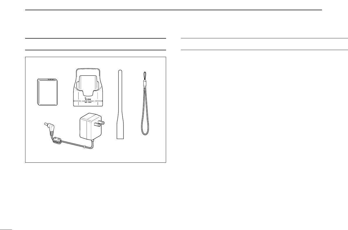
SUPPLIED ACCESSORIES
qBattery pack (BP-243) ………………………………………1
wBattery charger (BC-164) …………………………………1
eAntenna ………………………………………………………1
rHandstrap ……………………………………………………1
tAC adapter* (BC-145LA/LE/LV) ……………………………1
(The shape of the BC-145LA, BC-145LE and BC-145LV are differ-
ent.)
*Depending on versions. Not supplied with some versions.
qw er
t
TABLE OF CONTENTS
FOREWORD ............................................................................................. i
IMPORTANT ............................................................................................. i
EXPLICIT DEFINITIONS .......................................................................... i
PRECAUTION .......................................................................................... ii
SUPPLIED ACCESSORIES .................................................................... iii
TABLE OF CONTENTS ........................................................................... iii
QUICK REFERENCE GUIDE ........................................................... I–VIII
■Preparation........................................................................................ I
■Your first contact.............................................................................. III
■Repeater operation .......................................................................... V
■Memory programming..................................................................... VI
■Programmed scan operation.......................................................... VII
1PANEL DESCRIPTION ................................................................... 1–4
■Front, top and side panels ............................................................... 1
■Function display .............................................................................. 3
2BATTERY CHARGING ................................................................... 5–8
■Caution............................................................................................. 5
■Battery installation............................................................................ 7
■Battery charging ............................................................................... 8
3FREQUENCY AND CHANNEL SETTING .................................... 9–12
■VFO and memory channels.............................................................. 9
■Operating band selection ................................................................. 9
■Setting a frequency......................................................................... 11
■Setting a tuning step....................................................................... 11
■Selecting a memory channel.......................................................... 12
■Selecting a call channel.................................................................. 12
4BASIC OPERATION ................................................................... 13–18
■Receiving........................................................................................ 13
■Setting audio volume...................................................................... 13
■Squelch level setting ...................................................................... 14
■Operating mode selection .............................................................. 14
■Monitor function.............................................................................. 15
■Attenuator function ......................................................................... 15

iv
1
2
3
4
5
6
7
8
9
10
11
12
13
14
15
■Transmitting.................................................................................... 16
■Transmit power selection ............................................................... 16
■Dial select step............................................................................... 17
■Lock function .................................................................................. 18
■[DIAL] function assignment ............................................................ 18
5REPEATER OPERATION............................................................ 19–23
■General........................................................................................... 19
■Offset frequency............................................................................. 20
■Subaudible tones............................................................................ 21
■1750 Hz tone.................................................................................. 22
■Auto repeater function .................................................................... 23
6MEMORY/CALL CHANNELS ..................................................... 24–33
■General description ........................................................................ 24
■Memory channel programming....................................................... 24
■Memory bank setting...................................................................... 25
■Memory bank selection .................................................................. 26
■Programming memory/bank name ................................................. 27
■Selecting display type..................................................................... 28
■Copying memory contents.............................................................. 29
■Memory clearing............................................................................. 30
■Transferring memory contents ....................................................... 31
■Erasing/transferring bank contents................................................. 32
■Call channel programming ............................................................. 33
■Copying call channel contents........................................................ 33
7SCAN OPERATION .................................................................... 34–41
■Scan types...................................................................................... 34
■Full/band/programmed scan........................................................... 35
■Scan edges programming .............................................................. 36
■Memory/bank scan......................................................................... 37
■Auto memory write scan................................................................. 38
■Skip channel/frequency setting ...................................................... 39
■Scan resume condition................................................................... 41
8PRIORITY WATCH ..................................................................... 42–44
■Priority watch types ........................................................................ 42
■Priority watch operation.................................................................. 43
9TONE SQUELCH AND POCKET BEEP .................................... 45–48
■Tone/DTCS squelch operation ....................................................... 45
■Tone squelch frequency/DTCS code setting .................................. 46
■DTCS polarity setting ..................................................................... 47
■Tone scan ....................................................................................... 48
10 SET MODE ................................................................................. 49–59
■General........................................................................................... 49
■Set mode items .............................................................................. 50
11 OTHER FUNCTIONS ................................................................. 60–64
■Weather channel operation ............................................................ 60
■Data cloning .................................................................................. 61
■Auto power-off function .................................................................. 63
■TV channel operation ..................................................................... 63
■Partial reset .................................................................................... 64
■All reset ......................................................................................... 64
12 FREQUENCY TABLE ................................................................. 65–72
■TV channels ................................................................................... 65
■VHF marine channels..................................................................... 68
■Weather channels .......................................................................... 68
■Other communications in the USA ................................................. 69
■Other communications—other countries ........................................ 71
13 MAINTENANCE ......................................................................... 73–74
■Troubleshooting.............................................................................. 73
■Optional CP-21LR fuse replacement.............................................. 74
14 SPECIFICATIONS ...................................................................... 75–76
■Transceiver..................................................................................... 75
■Battery pack (BP-243).................................................................... 76
■Battery charger (BC-164) ............................................................... 76
15 OPTIONS .................................................................................... 77–79
■Options........................................................................................... 77
16 POCKET GUIDE ......................................................................... 80–81
16
17
I
QUICK REFERENCE GUIDE
■Preparation
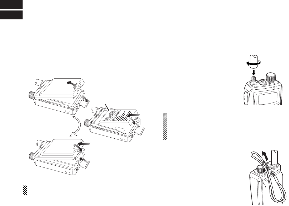
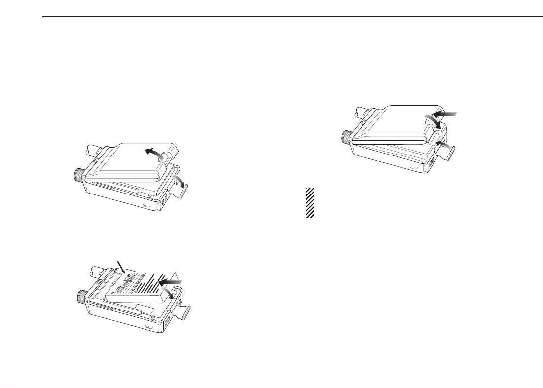
DBattery installation
qRemove the battery cover from the transceiver.
wInstall the BP-243 (Li-Ion battery pack).
•Be sure to observe the correct polarity.
eReplace the battery cover to the transceiver.
Keep the battery contacts clean. It’s a good idea to clean
the battery terminals once a week.
DDAntenna
Insert the supplied antenna into the
antenna connector and screw down
the antenna as shown at right.
NEVER hold the antenna when car-
rying the transceiver.
Keep the jack cover attached when
jack is not in use to protect the con-
nector from dust and moisture.
✔
For your information
Third-party antennas may increase transceiver perfor-
mance. An optional AD-92SMA
ANTENNA CONNECTOR
ADAPTER
is available to connect an antenna with a BNC
connector.
DHandstrap
Slide the handstrap through the
loop on the top of the rear panel as
illustrated at right. Facilities carry-
ing.
OrderOrder
Facing up this side
e
r
t
w
q
II
QUICK REFERENCE GUIDE
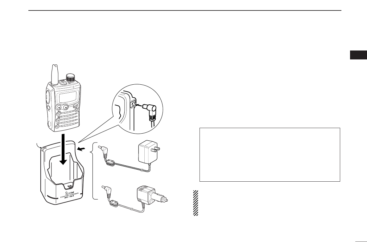
DCharging the battery
RRWARNING!:
NEVER charge any other than the specified battery pack.
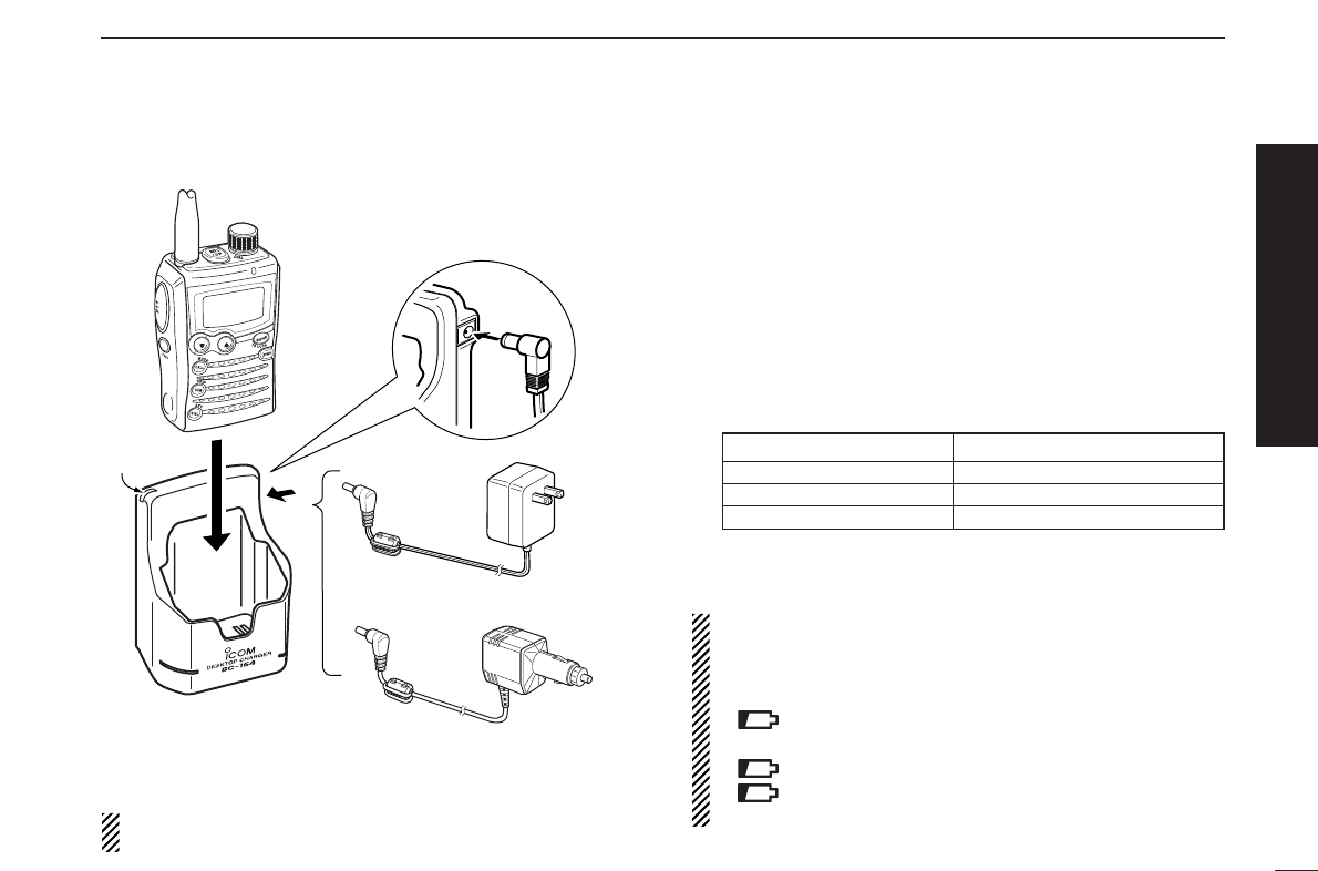
DCharging description
qPlug the AC adapter into an AC outlet; or the optional CP-
21LR into a cigarette lighter socket.
wInsert the adapter plug into [12~16V DC INPUT] of the BC-
164
BATTERY CHARGER
.
eInstall the BP-243
BATTERY PACK
(See left page) to the
transceiver
rBe sure to turn OFF the transceiver, then charge the bat-
tery with transceiver.
•Takes approximately 3 hours for fully charge with the supplied
BP-243 battery pack.
•Charging indicator of BC-164 lights or blinks as follows.
*It may be charging outside of the specified temperature range: +5˚C to
+35˚C (+41˚F to +95˚F). Restore the specified temperature range and
reinsert the transceiver.
NOTE: The transceiver has battery indicator to show the
following information.
•No indicator appears when the installed battery pack has
ample capacity.
•“” (battery indicator) appears when the battery pack
is nearing exhaustion.
•“” blinks when the battery pack must be charged.
•“” and “LOW” indicator appear just before the battery
pack is completely discharged and display turns OFF.
BC-164
Charging
indicator
Transceiver to [12~16V DC INPUT] jack
AC adapter
to cigarette
lighter socket
to AC outlet
SCAN
SET
S.MW
Optional CP-21LR
Cigarette lighter cable
with noise filter
Quick reference guide
Charging indicator status Charging status
Lights orange Charging
Lights green Charging is completed
Blinking red Charging error*
III
QUICK REFERENCE GUIDE
■Your first contact
Now that you have your IC-P7A ready, you are probably ex-
cited to get on the air. We would like to take you through a
few basic steps to make your first experience “On The Air” en-
joyable.
DAbout default settings
The [DIAL] control function can be exchanged with the
[YY]/[ZZ]key functions by pushing and holding [FUNC] then
push [YY]or [ZZ]. However, in this QUICK REFERENCE
GUIDE, the factory default setting ([DIAL] sets operating fre-
quency) is used to simplify the instructions.
DBasic operation
1. Turning ON the transceiver
➥Push and hold [PWR] for 1
sec. to turn the power ON.
•Opening indication passes
through, then frequency indica-
tion appears.
The opening indication can
be skipped. While pushing
and holding [FUNC], push
and hold [PWR] for 1 sec. to
shortcut the opening indica-
tion.
2. Adjusting audio level
➥Push [YY]/[ZZ]to set the desired audio level.
3. Adjusting squelch level
➥While pushing and holding [SQL] (
ATT
•
SET
), rotate [DIAL]
to set the squelch level.
SCAN
SET
S.MW
[DIAL]
[SQL]
SCAN
SET
S.MW
[Y]/[Z]
SCAN
SET
S.MW
[PWR]
IV
QUICK REFERENCE GUIDE
4. Tune the desired frequency
The tuning dial will allow you to dial in the frequency you want
to use. Pages 11 and 17 will instruct you on how to set the
tuning step size.
qPush [BAND] (
TS
•
LOCK
)sev-
eral times to select the de-
sired frequency band.
•While pushing and holding
[BAND] (
TS
•
LOCK
), rotating
[DIAL] also selects frequency
band.
wRotate [DIAL] to set the de-
sired frequency.
•While pushing and holding
[FUNC], rotate [DIAL] to select
frequency in 1 MHz steps.
5. Operating mode selection
➥While pushing and holding
[FUNC], push [CALL]
(
MODE
•
SCAN
)several times to
select the desired operating
mode.
•FM, WFM and AM modes are
selectable.
6. Transmit and receive
➥Push and hold [PTT] to trans-
mit then speak into the micro-
phone; release to receive.
•Transmission is available on the
144 MHz/440 MHz (FM mode)
amateur bands only.
SCAN
SET
S.MW
Microphone
[PTT]
SCAN
SET
S.MW
[CALL]
[FUNC]
SCAN
SET
S.MW
[FUNC]
[BAND]
[DIAL]
Quick reference guide
V
QUICK REFERENCE GUIDE
■Repeater operation
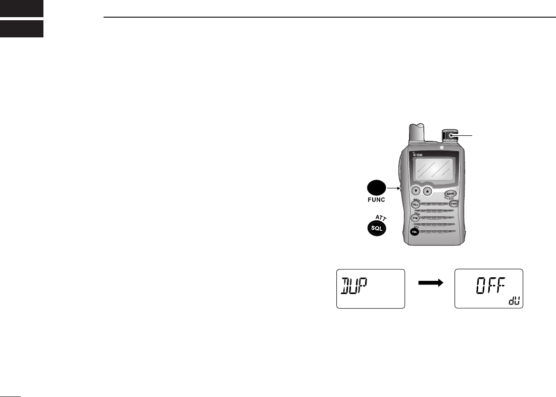
1. Setting duplex
qWhile pushing and holding
[FUNC], push and hold [SQL]
(
ATT
•
SET
)for 1 sec. to enter set
mode.
wRotate [DIAL] to select “DUP.”
eWhile pushing and holding
[FUNC], rotate [DIAL] to select
minus duplex or plus duplex.
•The USA/KOREA versions have
an auto repeater function, there-
fore setting duplex is not re-
quired.
rPush [SQL] (
ATT
•
SET
) to exit set mode.
2. Repeater tone
qWhile pushing and holding
[FUNC], push and hold [SQL]
(
ATT
•
SET
)for 1 sec. to enter set
mode.
wRotate [DIAL] to select
“T/TSQL.”
eWhile pushing and holding
[FUNC], rotate [DIAL] to select
the repeater tone activation.
rPush [SQL] (
ATT
•
SET
) to exit set mode.
ATT
DTCS
TSQL
WFMAM -DUP
LOW
VOL PRIO P S KI P
MR
5
19
ATT
DTCS
TSQL
WFMAM -DUP
LOW
VOL PRIO P S KI P
MR
5
19
ATT
DTCS
TSQL
WFMAM -DUP
LOW
VOL PRIO P S KI P
MR
5
19
SCAN
SET
S.MW
[SQL]
[FUNC]
[DIAL]
ATT
DTCS
T SQL
WFMAM -DUP
LOW
VOL PRIO P SK IP
MR
5
19
ATT
DTCS
TSQL
WFMAM -DUP
LOW
VOL PRIO P S KI P
MR
5
19
ATT
DTCS
TSQL
WFMAM -DUP
LOW
VOL PRIO P S KI P
MR
5
19
SCAN
SET
S.MW
[SQL]
[FUNC]
[DIAL]
VI
QUICK REFERENCE GUIDE
Quick reference guide
■Memory programming
The IC-P7A has a total of 1250 memory channels (including
200 auto write channels and 50 scan edges) for storing often
used operating frequency, mode, etc.
1. Setting frequency
In VFO mode, set the desired receive frequency mode.
•When “ ” indicator is displayed, push [V/M] (
SKIP
•
S
.
MW
)to select
the VFO mode.
2. Selecting a memory channel
Push [V/M] (
SKIP
•
S
.
MW
)for 1 sec. to
enter select memory write mode
(
1short and 1 long beep sound)
,
then rotate [DIAL] to select the de-
sired memory channel.
•“ ” indicator and memory channel
number blink.
•To cancel and exit select memory write mode, push
[V/M]
(
SKIP
•
S
.
MW
)
momentarily.
3. Writing a memory channel
Push and hold [V/M] (
SKIP
•
S
.
MW
)for 1 sec. until 3 beeps
sound.
•Memory channel number automatically increases when continuing
to push [V/M] (
SKIP
•
S
.
MW
)after programming.
SCAN
SET
S.MW
[V/M]
ATT
DTCS
TSQL
WFMAM -DUP
LOW
VOL PRIO P S KI P
MR
5
19
SCAN
SET
S.MW
[DIAL]
[V/M]
VII
QUICK REFERENCE GUIDE
■Programmed scan operation
50 channels of memories in 25 pairs are used to specify
scanning ranges for programmed scan operation. The pro-
grammed scan scans between “xxA” and “xxb” (xx=00 to 24)
channels. Therefore, before operating the programmed scan,
different frequencies must be programmed into the “A” and
“b” channels.
DDProgramming scan edges
Astart and stop frequency must be programmed into a pair
of "xxA" or "xxb" channels.
1. Setting frequency
In VFO mode, set the desired operating frequency and mode.
•When “ ” indicator is displayed, push [V/M] (
SKIP
•
S
.
MW
)to select
the VFO mode.
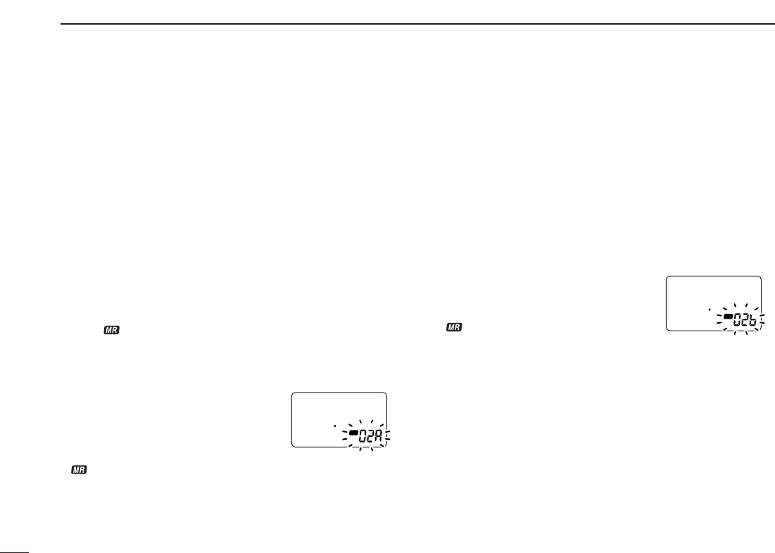
2. Selecting a scan edge channel “A”
Push and hold [V/M] (
SKIP
•
S
.
MW
)for 1
sec. to enter select memory write
mode (
1short and 1 long beep
sound)
,
then rotate [DIAL] to select
the desired scan edge channel “A.”
•“ ” indicator and scan edge channel
number blink.
3. Writing a memory channel
Push and hold [V/M] (
SKIP
•
S
.
MW
)for 1 sec. until 3 beeps
sound.
•Scan edge channel “b” is automatically selected when continuing to
push [V/M] (
SKIP
•
S
.
MW
)after programming.
•After programming is completed, the display returns to VFO indica-
tion.
4. Selecting a scan edge channel “b”
Push and hold [V/M] (
SKIP
•
S
.
MW
)for 1
sec.,
then rotate [DIAL] to select the
desired scan edge channel “b.”
•“ ” indicator and scan edge channel
number blink.
•When the scan edge channel “b” is already selected at step 3, con-
tinuing to push [V/M] (
SKIP
•
S
.
MW
)after programming, skip this step.
5. Writing a memory channel
Push and hold [V/M] (
SKIP
•
S
.
MW
)for 1 sec. until 3 beeps
sound.
•The next scan edge channel “A” is automatically selected when con-
tinuing to push [V/M] (
SKIP
•
S
.
MW
)after programming.
•After programming is completed, the display returns to VFO indica-
tion.
ATT
DTCS
TSQL
WFMAM -DUP
LOW
VOL PRIO P S KI P
MR
5
19
ATT
DTCS
TSQL
WFMAM -DUP
LOW
VOL PRIO P S KI P
MR
5
19
VIII
QUICK REFERENCE GUIDE
DDStarting scan
1. Select VFO mode.
Push [V/M] (
SKIP
•
S
.
MW
)to select the VFO mode for full, band
and programmed scan operation.
•Select memory mode by pushing [V/M] (
SKIP
•
S
.
MW
)again for mem-
ory or bank scan.
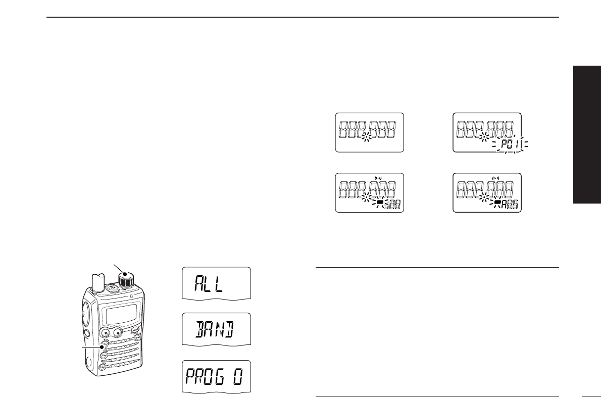
2. Selecting a scanning type
Push and hold [CALL] (
MODE
•
SCAN
)for 1 sec.,
then rotate
[DIAL] to select the desired scanning type.
•Available scan types when VFO mode is selected; “ALL” for full
scan; “BAND” for the selected band; one of “PROGxx” (xx=0 to 24)
for programmed scan.
•Available scan types when memory mode is selected; “M ALL” for all
memory scan “B ALL” for all bank scan, “B LINK” for bank link scan,
“BANK” for the selected bank scan.
3. Starting scan
Push [CALL] (
MODE
•
SCAN
)to start the scan.
•Rotate [DIAL] to change the scanning direction.
4. Cancelling scan
Push [CALL] (
MODE
•
SCAN
)again to stop scan.
✔
For your information
The memory channel number you program the scan edges
into correlate “PROGxx” as follows:
00A/00b: Select “PROG 00” to scan between frequencies
programmed in 00A and 00b channels.
01A/01b: Select “PROG 01” to scan between frequencies
programmed in 01A and 01b channels.
•
•
•
•
24A/24b: Select “PROG 24” to scan between frequencies
programmed in 24A and 24b channels.
ATT
DTCS
TSQL
WFMAM -DUP
LOW
VOL PRIO P S KI P
MR
5
19
ATT
DTCS
TSQL
WFMAM -DUP
LOW
VOL PRIO P S KI P
MR
5
19
ATT
DTCS
T SQL
WFMAM -DUP
LOW
VOL PRIO P S KI P
MR
5
19
ATT
DTCS
T SQL
WFMAM -DUP
LOW
VOL PRIO P S KI P
MR
5
19
• Programmed scan• Full/Band scan
• Bank scan
• All memory/All bank/
Bank link scan
SCAN
SET
S.MW
[DIAL]
[CALL]
• Full scan
• Scan type indication examples
• Programmed scan
• Band scan
Quick reference guide
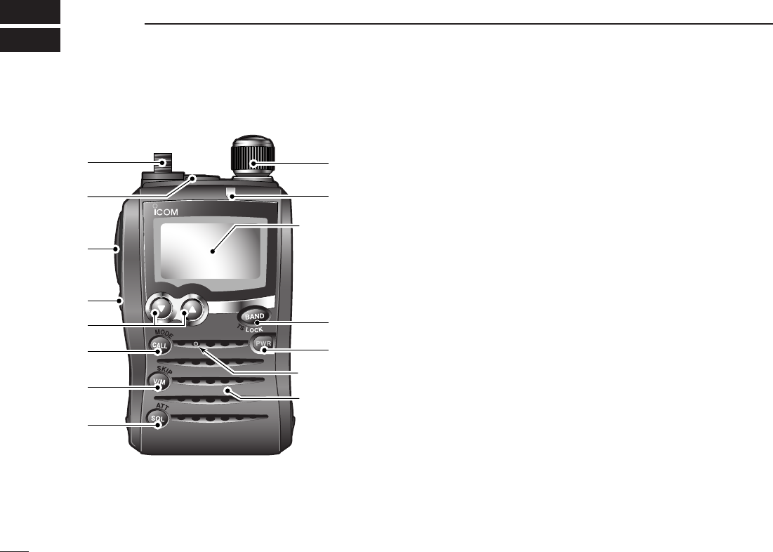
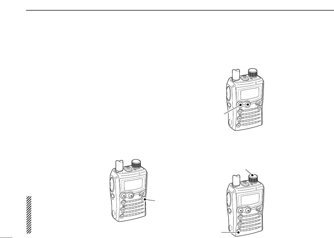
■Front, top and side panels
qANTENNA CONNECTOR (p. I)
Connects to the supplied antenna.
•An optional AD-92SMA adapter (p. 77) is available for connect-
ing an antenna with a BNC connector.
wEXTERNAL SPEAKER/MICROPHONE JACK [MIC/SP]
Connect an optional speaker-microphone or headset via
an optional OPC-782
PLUG ADAPTOR CABLE
, if desired.
The internal microphone and speaker will not function
when the OPC-782 is connected. (See p. 77 for a list of
available options.)
ePTT SWITCH [PTT] (p. 16)
➥Push and hold to transmit, release to receive.
➥While pushing and holding [FUNC], push to toggle the
transmit output power between High and Low.
rFUNCTION KEY [FUNC]
Push and hold this key for access to secondary functions.
tUP/DOWN KEYS [YY]/[ZZ]
➥Adjusts audio volume level.* (p. 13)
➥While pushing and holding [FUNC], push either key to
exchange [DIAL] and [YY]/[ZZ]function. (p. 18)
SCAN
S.MW
SET
Function display
(pgs 3, 4)
Speaker
Microphone
!1
!0
!2
t
r
y
u
i
e
w
q
o
1
PANEL DESCRIPTION
1
*The function of [DIAL] and [YY]/[ZZ]can be exchanged. See page
18 for details.

2
1
PANEL DESCRIPTION
1
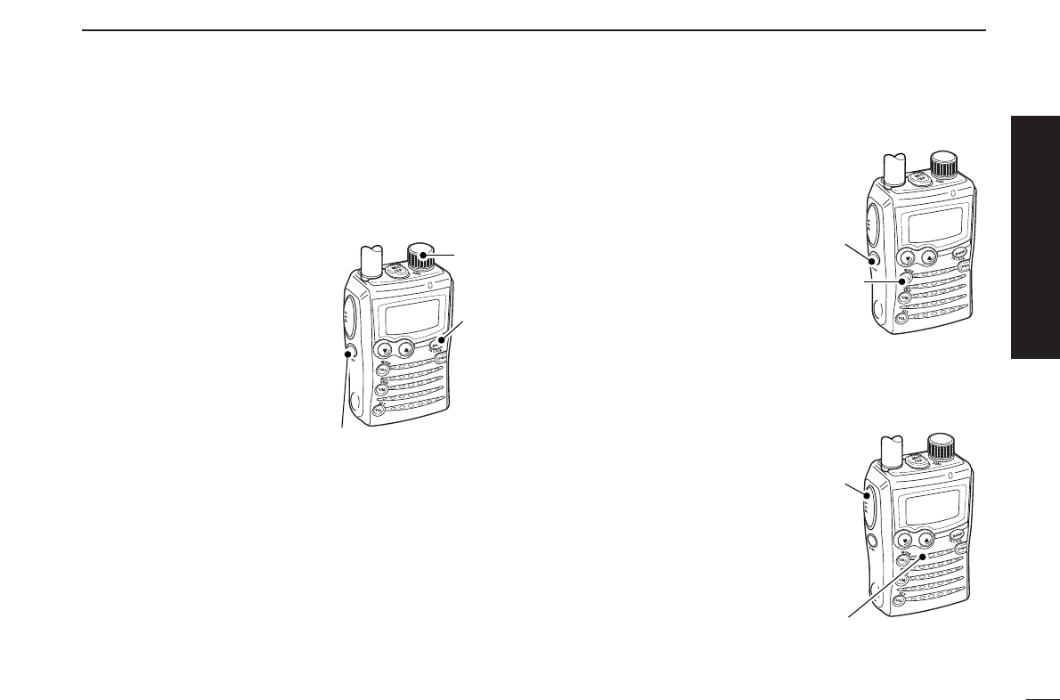
yCALL•MODE•SCAN KEY [CALL] (
MODE
•
SCAN
)
➥Push momentarily to select the call channel. (p. 12)
➥Push and hold for 1 sec. to enter the scan type selection
condition, push again to start a scan. (p. 35)
➥While pushing and holding [FUNC], push momentarily
to select the operating mode. (p. 14)
➥While pushing and holding [FUNC], push and hold for
1 sec. to start a tone scan. (p. 48)
uVFO/MEMORY•MEMORY WRITE KEY [V/M] (
SKIP
•
S
.
MW
)
➥Push momentarily to toggle between VFO and memory
mode. (p. 9)
➥Push and hold for 1 sec. to enter select memory write
mode. (p. 24)
➥While pushing and holding [FUNC], push momentarily
to select scan skip condition. (p. 40)
➥During VFO scan, pushing and holding [FUNC], push
and hold for 1 sec. to store into highest blank memory
channel as PSKIP channel (p. 40)
iSQUELCH•ATTENUATOR•SET KEY [SQL] (
ATT
•
SET
)
➥Push and hold to open the squelch temporarily and
monitor the operating frequency. (p. 15)
➥While pushing and holding this key, rotate [DIAL]* to ad-
just the squelch level. (p. 14)
➥While pushing and holding [FUNC], push and hold for
1 sec. to enter set mode. (p. 49)
oPOWER KEY [PWR]
Push and hold for 1 sec. to turn the transceiver power ON
and OFF.
!0BAND•TUNING STEP•LOCK KEY [BAND] (
TS
•
LOCK
)
➥Push to select the operating frequency band. (p. 9)
➥While pushing and holding [FUNC], push momentarily
to enter tuning step set mode. (p. 11)
➥While pushing and holding [FUNC], push and hold for
1 sec. to toggle the lock function ON and OFF. (p. 18)
!1TX RX INDICATOR [TX/RX] (pgs. 13, 16)
Lights green while receiving a signal or when the squelch
is open; lights red while transmitting.
!2CONTROL DIAL [DIAL]
➥Rotate to select the operating frequency.* (p. 11)
➥While scanning, changes the scanning direction.*
(p. 35)
➥While pushing and holding [SQL] (
ATT
•
SET
), sets the
squelch level.* (p. 14)
➥While pushing and holding [FUNC], changes the oper-
ating frequency in 100 kHz, 1 MHz or 10 MHz incre-
ments in VFO mode.* (p. 11)
➥While pushing and holding [FUNC], changes the mem-
ory channel in 10 channels steps in memory mode.*
(p. 12)
➥While pushing and holding [BAND] (
TS
•
LOCK
), selects
the operating band in VFO mode.* (p. 9)
➥While pushing and holding [BAND] (
TS
•
LOCK
), selects
the programmed bank or auto memory write channel in
memory mode.* (p. 9)
3
1PANEL DESCRIPTION
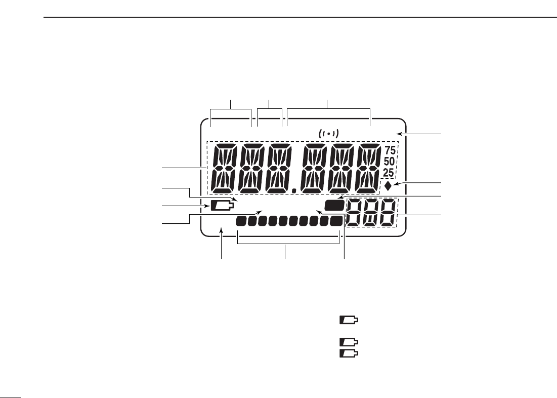
qFREQUENCY READOUT
Displays a variety of information, such as an operating fre-
quency, set mode contents, memory names.
•The smaller “75,” “50” and “25” on the right of the readout indi-
cate 0.75, 0.5 and 0.25 kHz, respectively.
•The decimal point blinks during scan.
wDIAL/VOLUME EXCHANGE INDICATOR (p. 18)
Appears when the function of [DIAL] and [YY]/[ZZ]are ex-
changed.
eBATTERY INDICATOR
➥No indicator appears when the installed battery pack
has ample capacity.
➥“” (battery indicator) appears when the battery
pack is nearing exhaustion.
➥“” blinks when the battery pack must be charged.
➥“” and “LOW” indicator appear just before the bat-
tery pack is completely discharged and display turns
OFF.
ATT
DTCS
T SQL
WFMAM -DUP
LOW
VOL PRIO P SKIP
MR
5
19
q
w
e
r
tyu
o
!4
!0
!3 !2
!1
i
■Function display

4
1
PANEL DESCRIPTION
1
rPRIORITY WATCH INDICATOR (p. 43)
Appears when priority watch is in use.
tLOW POWER INDICATOR (p. 16)
➥“LOW” appears when the low output power is selected.
➥No indicator appears when the high output power is se-
lected.
yS/RF METER
➥Shows the relative signal strength while receiving sig-
nals. (p. 13)
➥Shows the output power level while transmitting. (p. 16)
uSKIP INDICATORS (p. 39)
➥“SKIP” appears when the selected memory channel is
set as a skip channel.
➥“PSKIP” appears when the displayed frequency is sset
as a skip frequency.
iMEMORY CHANNEL NUMBER INDICATOR
➥Shows the selected memory channel number. (pgs. 12,
24)
➥“C” appears when the call channel is selected. (p. 12)
➥“L” appears when the lock function is active. (p. 18)
oMEMORY INDICATOR (pgs. 12, 24)
Appears when memory mode is selected.
!0AUTO WRITE CHANNEL INDICATOR (p. 38)
Appears when auto write channel is selected.
!1ATTENUATOR INDICATOR (p. 15)
Appears when the RF attenuator is in use.
!2TONE INDICATORS
➥“T” appears while the subaudible tone encoder is in use.
(p. 21)
➥“T SQL” appears while the tone squelch function is in
use. (p. 45)
➥“DTCS” appears while the DTCS squelch function is in
use. (p. 45)
➥“S” appears with the “T SQL” or “DTCS” indicator
while the pocket beep function (with CTCSS or DTCS) is
in use. (p. 45)
!3DUPLEX INDICATORS (p. 19)
“DUP” appears when plus duplex, “–DUP” appears when
minus duplex (repeater operation) is selected.
!4OPERATING MODE INDICATOR (p. 14)
Shows the selected operating mode.
•FM, WFM and AM are available.

5
BATTERY CHARGING
2
■Caution
•RDANGER! Use and charge only specified Icom battery
packs with Icom radios. Only Icom battery packs are tested
and approved for use with Icom radios. Using third-party or
counterfeit battery packs may cause smoke, fire, or cause
the battery to burst.
DDBattery caution
•RDANGER! DO NOT hammer or otherwise impact the bat-
tery. Do not use the battery if it has been severely impacted
or dropped, or if the battery has been subjected to heavy
pressure. Battery damage may not be visible on the outside
of the case. Even if the surface of the battery does not show
cracks or any other damage, the cells inside the battery may
rupture or catch fire.
•RDANGER! NEVER use or leave battery pack in areas
with temperatures above +60˚C (+140˚F). High temperature
buildup in the battery, such as could occur near fires or
stoves, inside a sun heated car, or in direct sunlight may
cause the battery to rupture or catch fire. Excessive temper-
atures may also degrade battery performance or shorten
battery life.
•RDANGER! DO NOT expose the battery to rain, snow,
seawater, or any other liquids. Do not charge or use a wet
battery. If the battery gets wet, be sure to wipe it dry before
using. The battery by itself is not waterproof.
•RDANGER! NEVER incinerate used battery pack since in-
ternal battery gas may cause it to rupture, or may cause an
explosion.
•RDANGER! NEVER solder the battery terminals. This may
cause heat generation, and the battery may burst, emit
smoke or catch fire.
•RDANGER! Use the battery only with the transceiver for
which it is specified. Never use a battery with any other
equipment, or for any purpose that is not specified in this in-
struction manual.
•RDANGER! If fluid from inside the battery gets in your
eyes, blindness can result. Rinse your eyes with clean
water, without rubbing them, and see a doctor immediately.
•WARNING! Immediately stop using the battery if it emits an
abnormal odor, heats up, or is discolored or deformed. If any
of these conditions occur, contact your Icom dealer or dis-
tributor.
•WARNING! Immediately wash, using clean water, any part
of the body that comes into contact with fluid from inside the
battery.
Misuse of LiTHIUM-ion batteries may result in the fol-
lowing hazards: smoke, fire, or the the battery may rup-
ture. Misuse can also cause damage to the battery or
degradation of battery performance.

6
2
BATTERY CHARGING
2
•WARNING! NEVER put the battery in a microwave oven,
high-pressure container, or in an induction heating cooker.
This could cause a fire, overheating, or cause the battery to
rupture.
•CAUTION! Always use the battery within the specified tem-
perature range for the transceiver (–10˚C to +60˚C; +14˚F
to +140˚F) and the battery itself (–20˚C to +60˚C; –4˚F to
+140˚F). Using the battery out of its specified temperature
range will reduce the battery’s performance and battery life.
Please note that the specified temperature range of the bat-
tery may exceed that of the transceiver. In such cases, the
transceiver may not work properly because it is out of its op-
erating temperature range.
•CAUTION! Shorter battery life could occur if the battery is
left fully charged, completely discharged, or in an excessive
temperature environment (above +50˚C; +122˚F) for an ex-
tended period of time. If the battery must be left unused for a
long time, it must be detached from the radio after discharg-
ing. You may use the battery until the battery indicator
shows half-capacity, then keep it safely in a cool dry place
with the temperature between –20˚C to +20˚C (–4˚F to
+68˚F).
DDCharging caution
•RDANGER! NEVER charge the battery pack in areas with
extremely high temperatures, such as near fires or stoves,
inside a sun heated car, or in direct sunlight. In such envi-
ronments, the safety/protection circuit in the battery will acti-
vate, causing the battery to stop charging.
•WARNING! DO NOT charge or leave the battery in the bat-
tery charger beyond the specified time for charging. If the
battery is not completely charged by the specified time, stop
charging and remove the battery from the battery charger.
Continuing to charge the battery beyond the specified time
limit may cause a fire, overheating, or the battery may
ruprute.
•WARNING! NEVER insert the transceiver (battery attached
to the transceiver) into the charger if it is wet or soiled. This
could corrode the battery charger terminals or damage the
charger. The charger is not waterproof.
•CAUTION! DO NOT charge the battery outside of the spec-
ified temperature range: +5˚C to +35˚C (+41˚F to +95˚F).
Icom recommends charging the battery at +20˚C (+68˚F).
The battery may heat up or rupture if charged out of the
specified temperature range. Additionally, battery perfor-
mance or battery life may be reduced.
7
2BATTERY CHARGING
■Battery installation
Before installing, or replacing the battery pack, be sure to turn
OFF the transceiver. If it’s ON, push and hold [PWR] for 1
sec. to turn the power OFF.
qRemove the battery cover from the transceiver.
wInstall the BP-243 (Li-Ion battery pack).
•Be sure to observe the correct polarity.
eReplace the battery cover to the transceiver.
Keep the battery contacts clean to avoid rust or poor con-
tact. It’s a good idea to clean the battery terminals once a
week.
r
t
e
Facing up this side
w
q
8
2
BATTERY CHARGING
2
■Battery charging
DCharging connections
•Charging periods: Approx. 3 hours
DCharging description
qPlug the AC adapter into an AC outlet; or the optional CP-
21LR into a cigarette lighter socket.
wInsert the adapter plug into [12~16V DC INPUT] of the BC-
164
BATTERY CHARGER
.
eInstall the BP-243
BATTERY PACK
(See left page) in the
transceiver
rBe sure to turn OFF the transceiver, then charge the bat-
tery with transceiver.
•Takes approximately 3 hours to fully charge with the supplied BP-
243 battery pack.
CAUTION: BE SURE to disconnect the CP-21LR from the
cigarette lighter socket when charging is finished, because,
a slight current still follows in the CP-21LR and the vehi-
cle’s battery will become will be drained.
Charging indicator of BC -164
Orange (lights) : During charging.
Green (lights) : When the battery pack is charged completely.
Red (blinking) : Thecharger may be outside of the specified
temperature range: +5˚C to +35˚C (+41˚F to
+95˚F). Restore the specified temperature
range and reinsert the transceiver or contact
your dealer.
BC-164
Charging
indicator
Transceiver to [12~16V DC INPUT] jack
AC adapter
to cigarette
lighter socket
to AC outlet
SCAN
SET
S.MW
Optional CP-21LR
Cigarette lighter cable
with noise filter
9
FREQUENCY AND CHANNEL SETTING
3
■VFO and memory channels
The IC-P7A has two primary operating modes: VFO mode
and memory mode.
VFO mode is used for setting the desired frequency within
the frequency coverage.
➥Push [V/M] (
SKIP
•
S
.
MW
)to select VFO mode.
Memory mode is used for operating from memory channels
which have programmed frequencies.
➥Push [V/M] (
SKIP
•
S
.
MW
)to select memory mode.
•See p. 24 for memory programming details.
What is VFO?
VFO is an abbreviation of Variable Frequency Oscillator. Fre-
quencies for receiving or transmitting are selected and con-
trolled by the VFO.
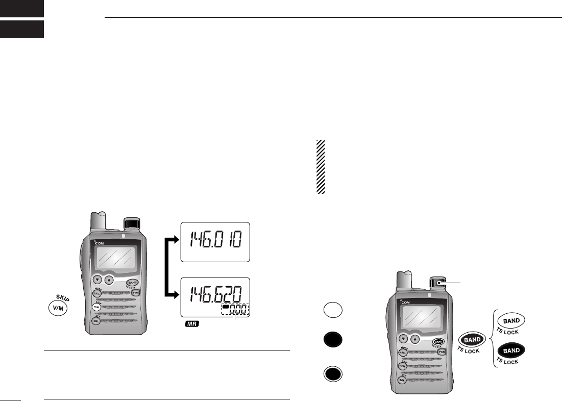
■Operating band selection
The transceiver can receive the AM broadcast, HF band,
50 MHz, FM broadcast, VHF air, 144 MHz, 300 MHz,
400 MHz, 600 MHz, *800 MHz, television channels or
†Weather channels.
Available frequency bands are differ depending on version.
See the specification for details. (p. 75)
*Some frequency ranges are inhibited for the USA version
due to local regulation.
†Available for the USA version only.
➥Push [BAND] (
TS
•
LOCK
)several times to select the desired
frequency band.
•When memory mode is selected, push [V/M] (
SKIP
•
S
.
MW
)to se-
lect VFO mode first.
➥While pushing and holding [BAND] (
TS
•
LOCK
), rotating
[DIAL] also selects frequency band.
SCAN
S.MW
SET
[DIAL]
[DIAL]
Push
Dual operation
Push and hold +
SCAN
SET
S.MW
ATT
DTCS
TSQL
WFMAM -DUP
LOW
VOL PRIO P S KI P
MR
5
19
ATT
DTCS
TSQL
WFMAM -DUP
LOW
VOL PRIO P S KI P
MR
5
19
“ ” and memory channel
number appear.
• VFO mode indication
• Memory mode indication
S.MW
10
3
FREQUENCY AND CHANNEL SETTING
3
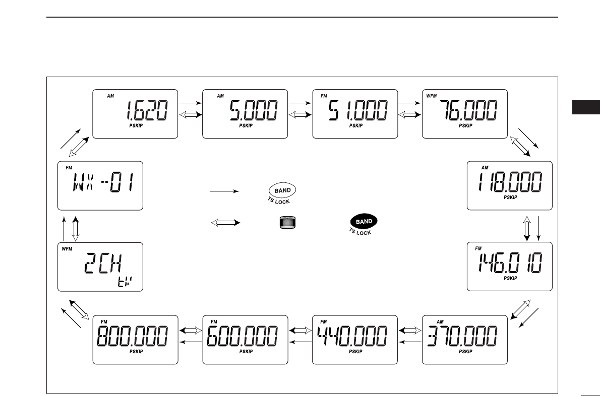
• Available frequency bands
AM broadcast band HF band 50 MHz band
600 MHz band800 MHz band 400 MHz band
FM broadcast band
VHF air band
144 MHz band
300 MHz band
Weather channels*
TV channels†
: Push
: Rotating while pushing
Initial frequencies shown differ according to version.
*Available for the USA version only
†Appears only when TV channels are programmed using the
optional CS-P7.
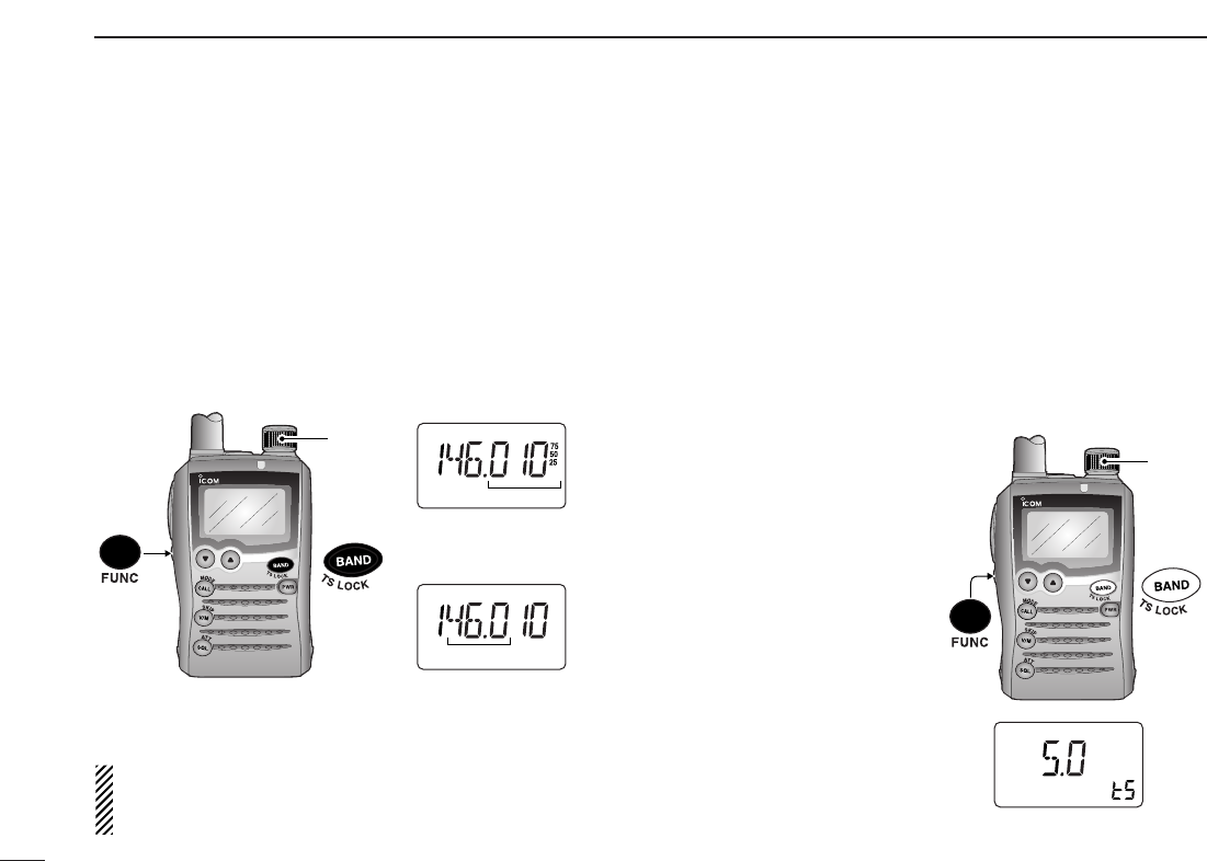
■Setting a frequency
qPush [V/M] (
SKIP
•
S
.
MW
)to select VFO mode, if necessary.
wSelect the desired frequency band with [BAND] (
TS
•
LOCK
).
•Or, while pushing and holding [BAND] (
TS
•
LOCK
), rotate [DIAL]
to select the desired frequency band.
eRotate [DIAL] to select the desired frequency.
•The frequency changes according to the preset tuning steps.
See the section at right for setting the tuning step.
•While pushing and holding [FUNC], rotate [DIAL] to change the
frequency in 1 MHz steps (default).
The 1 MHz tuning step (dial select step) can be set to
100 kHz, 1 MHz or 10 MHz tuning steps in set mode. See
p. 17 for details.
■Setting a tuning step
The tuning step can be selected for each frequency band.
The following tuning steps are available for the IC-P7A.
•5.0 kHz* • 6.25 kHz* • 8.33 kHz†•9.0 kHz‡•10.0 kHz
•12.5 kHz • 15.0 kHz • 20.0 kHz • 25.0 kHz • 30.0 kHz
•50.0 kHz • 100.0 kHz • 200.0 kHz
* Appears for below the 500 MHz bands only.
†Appears for the VHF air band only.
‡Appears for the AM broadcast band only.
DDTuning step selection
qPush [V/M] (
SKIP
•
S
.
MW
)to
select VFO mode, if neces-
sary.
wPush [BAND] (
TS
•
LOCK
)
several times to select the
desired frequency band.
•Or, while pushing and hold-
ing [BAND] (
TS
•
LOCK
), rotate
[DIAL] to select the desired
frequency band.
e
While pushing and holding
[FUNC], push [BAND]
(
TS
•
LOCK
)momentarily to
enter tuning step set mode.
rRotate [DIAL] to select the
desired tuning step.
tPush [BAND] (
TS
•
LOCK
)to
return to VFO mode.
SCAN
SET
S.MW
ATT
DTCS
TSQL
WFMAM -DUP
LOW
VOL PRIO P S KI P
MR
5
19
[DIAL]
5 kHz tuning step
SCAN
SET
S.MW
ATT
DTCS
TSQL
WFMAM -DUP
LOW
VOL PRIO P S KI P
MR
5
19
ATT
DTCS
TSQL
WFMAM -DUP
LOW
VOL PRIO P S KI P
MR
5
19
[DIAL] changes the fre-
quency according to the
selected tuning step.
While pushing [FUNC],
[DIAL] changes the frequen-
cy in 1 MHz steps (default).
[DIAL]
11
3FREQUENCY AND CHANNEL SETTING
12
3
FREQUENCY AND CHANNEL SETTING
3
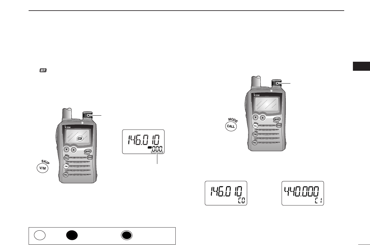
■Selecting a memory channel
qPush [V/M] (
SKIP
•
S
.
MW
)momentarily to select memory
mode.
•“ ” appears when a memory channel is selected.
wRotate [DIAL] to select the desired memory channel.
•Only programmed memory channels can be selected.
•While pushing and holding [FUNC], rotate [DIAL] to select a
memory channel in 10 channel steps, blank channels can be se-
lected in this case.
■Selecting a call channel
qPush [CALL] (
MODE
•
SCAN
)momentarily to select a call
channel.
wRotate [DIAL] to select the desired call channel.
ePush [CALL] (
MODE
•
SCAN
)or [V/M] (
SKIP
•
S
.
MW
) momen-
tarily to return to the previously selected mode.
ATT
DTCS
TSQL
WFMAM -DUP
LOW
VOL PRIO P S KI P
MR
5
19
ATT
DTCS
TSQL
WFMAM -DUP
LOW
VOL PRIO P S KI P
MR
5
19
144 MHz band 440 MHz band
• Call channel example (depends on version)
SCAN
S.MW
SET
SCAN
[DIAL]
SCAN
S.MW
SET
ATT
DTCS
TSQL
WFMAM -DUP
LOW
VOL PRIO P S KI P
MR
5
19
[DIAL]
[DIAL] changes the mem-
ory channel.
S.MW
Push Push and hold Dual operation
■Receiving
Make sure charged battery pack (BP-243) is installed (p. 7).
qPush and hold [PWR] for 1 sec. to turn power ON.
wPush [YY]or [ZZ]to set the desired audio level.
•The frequency display shows the volume level while setting. See
the section at right for details.
eSet the receiving frequency. (p. 11)
rSet the squelch level. (p. 14)
•While pushing and holding [SQL] (
ATT
•
SET
), rotate [DIAL].
•The first click of [DIAL] indicates the current squelch level.
•“LEVEL 1” is loose squelch (for weak signals) and “LEVEL 9” is
tight squelch (for strong signals).
•“AUTO” indicates automatic level adjustment by a noise pulse
counting system.
•Push and hold [SQL] (
ATT
•
SET
)to open the squelch manually.
tWhen a signal is received:
•TX/RX indicator lights green.
•Squelch opens and audio is emitted.
•The S/RF meter shows the relative signal strength level.
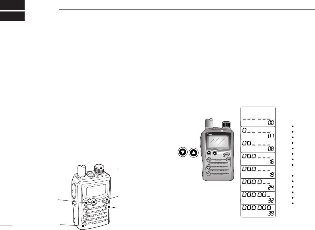
■Setting audio volume
The audio level can be adjusted to one of 40 levels.
➥P
ush [YY]or [ZZ]to adjust the audio level.
•If squelch is closed, push and hold [SQL] (
ATT
•
SET
)to verify the
audio level.
•Pushing and holding either key changes the audio level continu-
ously.
•The display shows the volume level while setting.
SCAN
S.MW
SET
INDICATION AUDIO LEVEL
Minimum setting
(no audio)
Muximum setting
Initial setting
SCAN
SET
S.MW
q [PWR]
e Set frequency
r Set squelch level
w Set audio level e Select band
r Push for setting
the squelch
(Push to monitor)
13
BASIC OPERATION
4
14
4
BASIC OPERATION
4
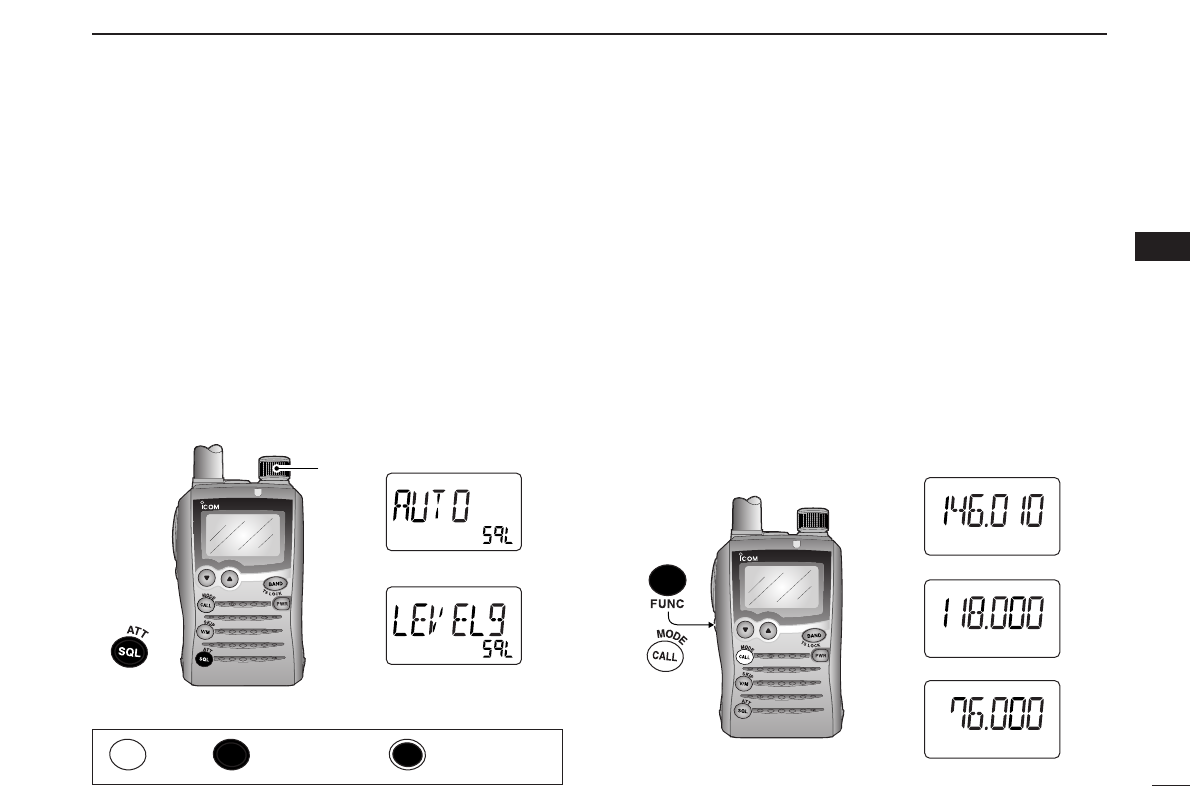
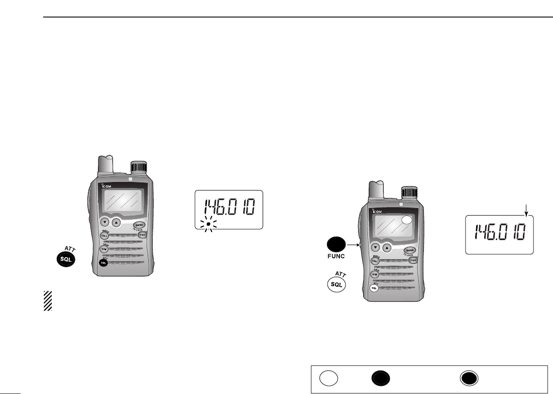
■Squelch level setting
The squelch circuit mutes the received audio signal depend-
ing on the signal strength. The transceiver has 9 squelch lev-
els, a continuously open setting and an automatic squelch
setting.
➥While pushing and holding [SQL] (
ATT
•
SET
), rotate [DIAL]
to select the squelch level.
•“LEVEL 1” is loose squelch (for weak signals) and “LEVEL 9” is
tight squelch (for strong signals).
•“AUTO” indicates automatic level adjustment by a noise pulse
counting system.
•“OPEN” indicates continuously open setting.
■Operating mode selection
Operating modes are determined by the modulation of the
radio signals. The transceiver has 3 operating modes: FM,
AM and WFM modes. The mode selection is stored indepen-
dently in each band and memory channels.
Typically, AM mode is used for the AM broadcast stations
(0.495–1.620 MHz) and air band (118–135.995 MHz), and
WFM is used for FM broadcast stations (76–107.9 MHz).
WFM mode cannot be selected below 30 MHz bands for all
versions (and above 850 MHz bands for USA version).
➥While pushing and holding [FUNC], push [CALL]
(
MODE
•
SCAN
)several times to select the desired operating
mode.
SCAN
S.MW
ATT
DTCS
TSQL
WFMAM -DUP
LOW
VOL PRIO P S KI P
MR
5
19
ATT
DTCS
TSQL
WFMAM -DUP
LOW
VOL PRIO P S KI P
MR
5
19
ATT
DTCS
TSQL
WFMAM -DUP
LOW
VOL PRIO P SKIP
MR
5
19
FM mode
AM mode
WFM mode
SCAN
SET
SCAN
S.MW
SET
ATT
DTCS
TSQL
WFMAM -DUP
LOW
VOL PRIO P S KI P
MR
5
19
ATT
DTCS
TSQL
WFMAM -DUP
LOW
VOL PRIO P S KI P
MR
5
19
[DIAL]
Automatic squelch
Maximum level
SET
Push Push and hold Dual operation
■Monitor function
This function is used to listen to weak signals without disturb-
ing the squelch setting or to open the squelch manually even
when mute functions such as the tone squelch are in use.
➥Push and hold [SQL] (
ATT
•
SET
)to monitor the operating
frequency.
The [SQL] (
ATT
•
SET
)key can be set to ‘sticky’ operation in
expanded set mode. See page 56 for details.
■Attenuator function
The attenuator prevents distortion of a desired signal when
very strong RF signals are near the desired frequency or
when very strong electric fields, such as from a broadcasting
station, are present at your location.
➥
While pushing and holding [FUNC], push [SQL] (
ATT
•
SET
)
momentarily to toggle the attenuator function ON and OFF.
•“ATT” appears when the attenuator functions is in use.
SCAN
S.MW
SET
ATT
DTCS
TSQL
WFMAM -DUP
LOW
VOL PRIO P SKIP
MR
5
19
ATT
SET
Appears
SCAN
S.MW
SET
ATT
DTCS
TSQL
WFMAM -DUP
LOW
VOL PRIO P S KI P
MR
5
19
The 1st segment blinks
SET
15
4BASIC OPERATION
Push Push and hold Dual operation
16
4
BASIC OPERATION
4
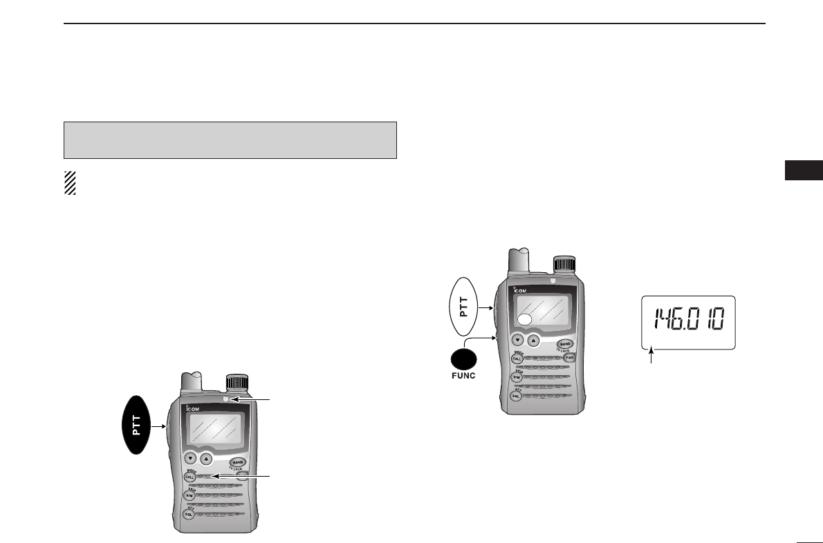
■Transmitting
NOTE: To prevent interference, listen on the channel be-
fore transmitting by pushing and holding [SQL] (
ATT
•
SET
).
qSet the operating frequency. (pgs. 9, 11)
•Transmission is available on the 144 MHz/440 MHz (FM mode)
amateur bands only.
•Select output power if desired. See the section at right for details.
wPush and hold [PTT] to transmit.
•TX/RX indicator lights red.
•S/RF meter shows the output power level.
eSpeak into the microphone using your normal voice level.
•DO NOT hold the transceiver too close to your mouth or speak
too loudly. This may distort the signal.
rRelease [PTT] to return to receive.
■Transmit power selection
The transceiver has two output power levels to suit your op-
erating requirements. Low output power during short-range
communications may reduce the possibility of interference to
other stations and will reduce current consumption.
➥
While pushing and holding [FUNC], push [PTT] to toggle
the transmit output power between High and Low.
•“LOW” appears when the low power is selected.
SCAN
S.MW
SET
DTCS
TSQL
WFMAM -DUP
LOW
LOW
VOL PRIO P S KI P
MR
5
19
Appears
SCAN
S.MW
SET
TX/RX indicator
Microphone
CAUTION: Transmitting without an antenna will damage
the transceiver.
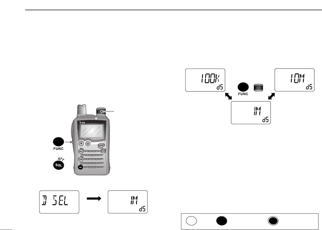
This transceiver has a 1 MHz tuning step for quick frequency
setting. This dial select step can be set to 100 kHz, 1 MHz or
10 MHz steps, as desired.
DDSetting dial select step
qSelect VFO mode with [V/M] (
SKIP
•
S
.
MW
).
wWhile pushing and holding [FUNC], push and hold
[SQL] (
ATT
•
SET
)for 1 sec. to enter set mode.
eRotate [DIAL] to select “D SEL.”
rWhile pushing and holding [FUNC], rotate [DIAL] to select
the desired dial select step.
tPush [SQL] (
ATT
•
SET
)momentarily to exit set mode.
ATT
DTCS
TSQL
WFMAM -DUP
LOW
VOL PRIO P S KI P
MR
5
19
ATT
DTCS
TSQL
WFMAM -DUP
LOW
VOL PRIO P S KI P
MR
5
19
ATT
DTCS
TSQL
WFMAM -DUP
LOW
VOL PRIO P S KI P
MR
5
19
1 MHz step (default)
100 kHz step 10 MHz step
+
ATT
DTCS
TSQL
WFMAM -DUP
LOW
VOL PRIO P S KI P
MR
5
19
ATT
DTCS
TSQL
WFMAM -DUP
LOW
VOL PRIO P S KI P
MR
5
19
After 1 sec.
Dial select step item Setting indication
SCAN
S.MW
SET
[DIAL]
SET
17
4BASIC OPERATION
Push Push and hold Dual operation
■Dial select step [
18
4
BASIC OPERATION
4
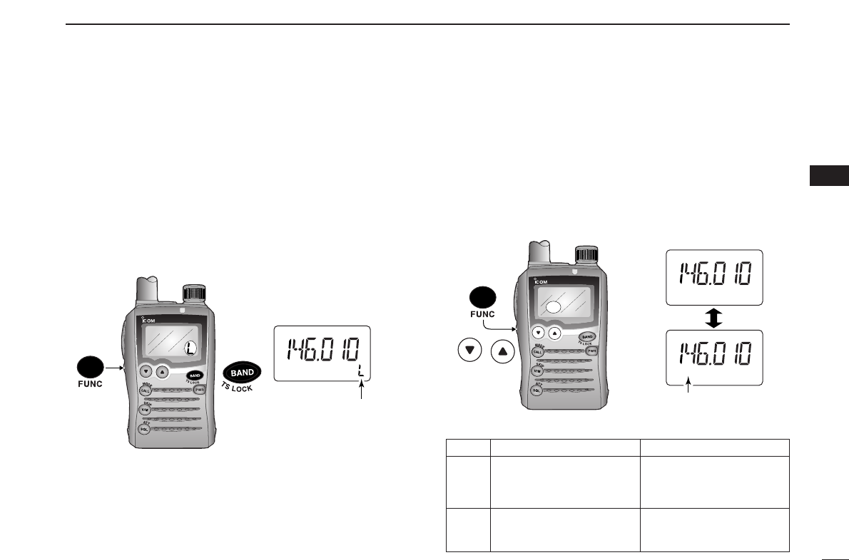
■[DIAL] function assignment
The [DIAL] control can be used as an audio volume control
instead of [YY]/[ZZ]keys to suit your preference. However,
while [DIAL] functions as an audio volume, [YY]/[ZZ]keys func-
tion as tuning controls.
➥
While pushing and holding [FUNC], push [YY]/[ZZ]to toggle
the [DIAL] function between tuning dial and audio volume.
•“VOL” appears when [DIAL] functions as an audio volume.
•[DIAL] and [YY]/[ZZ] functions
SCAN
S.MW
SET
ATT
DTCS
TSQL
WFMAM -DUP
LOW
VOL
VOL
PRIO P SKIP
MR
5
19
ATT
DTCS
TSQL
WFMAM -DUP
LOW
VOL PRIO P S KI P
MR
5
19
Appears
or
■Lock function
To prevent accidental frequency changes and unnecessary
function activation, use the lock function.
➥While pushing and holding [FUNC], push and hold
[BAND] (
TS
•
LOCK
)for 1 sec. to turn the lock function ON
and OFF.
•“L” appears while the lock function is active.
•[SQL] (
ATT
•
SET
)and [YY]/[ZZ]can be used while the lock function
is in use in default setting. Either or both [SQL] (
ATT
•
SET
)and
[YY]/[ZZ]keys may also be locked in set mode. (p. 56)
SCAN
S.MW
SET
ATT
DTCS
TSQL
WFMAM -DUP
LOW
VOL PRIO P S KI P
MR
5
19
Appears
No “VOL” indication “VOL” appears
Frequency, Memory channel,
Audio volume set
[DIAL] Squelch level, Scanning Set mode condition set
direction, Set mode item
and condition set
Audio volume set
Frequency, Memory channel,
[YY]/[ZZ]Squelch level, Scanning
direction, Set mode item
19
REPEATER OPERATION
5
When using a repeater, the transmit frequency is shifted from
the receive frequency by the amount of the offset frequency. It
is convenient to program repeater information, such as offset
and access tone, into memory channels.
qSet the receive frequency (repeater output frequency).
wSet the shift direction of the transmit offset frequency. (–DUP
or +DUP; see the next section for details.)
• “–DUP” or “+DUP” indicates a minus or plus offset of the transmit
frequency, respectively.
•When the auto repeater function is in use (USA/KOREA versions
only), this selection and step eare not necessary. (p. 23)
eActivate the subaudible tone encoder, according to re-
peater requirements.
•Refer to page 21 for tone frequency settings.
rPush and hold [PTT] to transmit.
•The displayed frequency automatically changes to the transmit
frequency (repeater input frequency).
•If “OFF” appears, check the offset frequency (see next page for
details) or shift direction (see section at right).
tRelease [PTT] to receive.
yPush and hold [SQL] (
ATT
•
SET
)to check whether the other
station’s transmit signal can be received directly on the re-
peater’s input frequency.
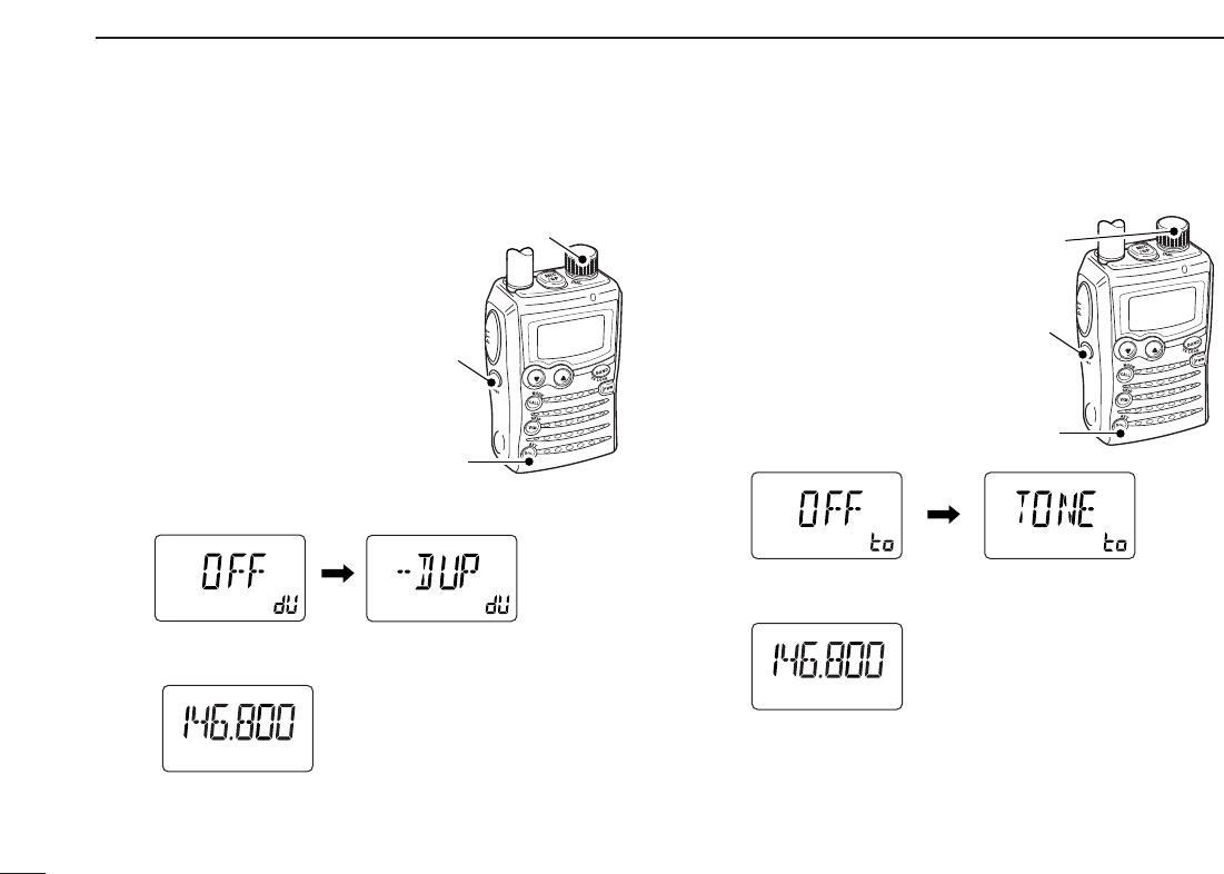
DDSetting duplex and duplex direction
qWhile pushing and holding [FUNC], push and hold
[SQL] (
ATT
•
SET
)for 1 sec. to enter set mode.
wRotate [DIAL] to select “DUP.”
eWhile pushing and holding [FUNC], rotate [DIAL] to select
“–DUP” or “+DUP.”
rPush [SQL] (
ATT
•
SET
) to exit set mode.
tPush and hold [SQL] (
ATT
•
SET
)to monitor the repeater
input frequency.
ATT
DTCS
TSQL
WFMAM -DUP
LOW
VOL PRIO P S KI P
MR
5
19
ATT
DTCS
TSQL
WFMAM -DUP
LOW
VOL PRIO P S KI P
MR
5
19
After 1 sec.
Duplex item Setting indication
SCAN
S.MW
SET
[DIAL]
SET
■General
20
5
REPEATER OPERATION
5
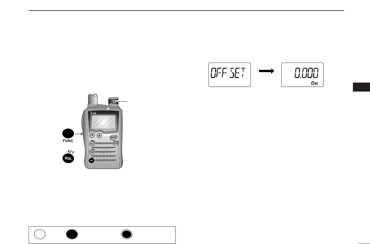
When communicating through a repeater, the transmit fre-
quency is shifted from the receive frequency by the amount of
the offset frequency.
qWhile pushing and holding [FUNC], push and hold
[SQL] (
ATT
•
SET
)for 1 sec. to enter set mode.
wRotate [DIAL] to select “OFFSET.”
eWhile pushing and holding [FUNC], rotate [DIAL] to set the
desired offset frequency within 0.000–159.995 MHz range.
•The tuning step, selected in VFO mode, is used for setting.
rPush [SQL] (
ATT
•
SET
)to exit set mode.
ATT
DTCS
TSQL
WFMAM -DUP
LOW
VOL PRIO P S KI P
MR
5
19
ATT
DTCS
TSQL
WFMAM -DUP
LOW
VOL PRIO P S KI P
MR
5
19
After 1 sec.
Offset frequency item Setting indication
SCAN
S.MW
SET
[DIAL]
SET
■Offset frequency
Push Push and hold Dual operation
21
5REPEATER OPERATION
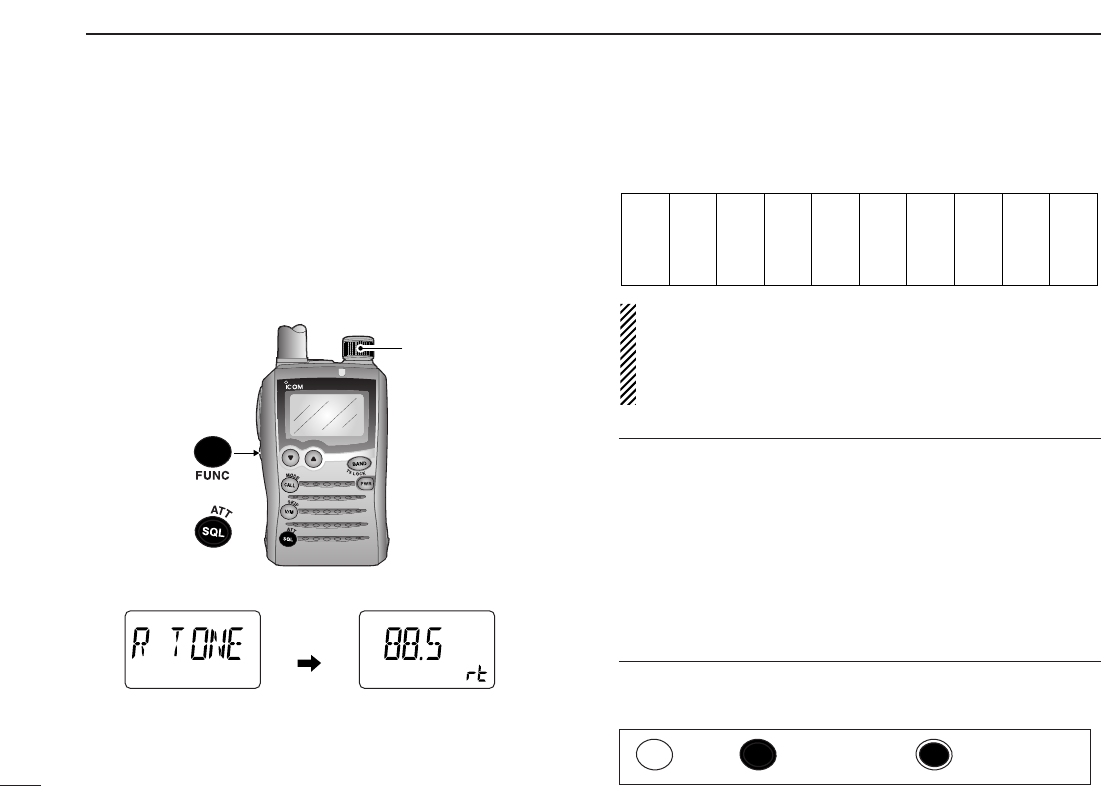
To be accessed, some repeaters require subaudible tones on
the input signal. Subaudible tones are added to your normal
signal and must be set in advance.
DDSetting the subaudible tone frequency
qWhile pushing and holding [FUNC], push and hold
[SQL] (
ATT
•
SET
)for 1 sec. to enter set mode.
wRotate [DIAL] to select “R TONE.”
eWhile pushing and holding [FUNC], rotate [DIAL] to select
the desired subaudible tone frequency.
•See the tables at right.
rPush [SQL] (
ATT
•
SET
)to exit set mode.
•Available tone frequency list
NOTE: The transceiver has 50 tone frequencies and con-
sequently their spacing is narrow compared to units having
38 tones. Therefore, systems using some tone frequencies
may receive interference from signals using adjacent tone
frequencies.
✔
CONVENIENT!
Tone scan function: When you don’t know the subaudible
tone used for a repeater, the tone scan is convenient for de-
tecting the tone frequency. (p. 48)
While pushing and holding [FUNC], pushing and holding
[CALL] (
MODE
•
SCAN
)for 1 sec. to start the repeater tone
scan.
• Push [CALL] (
MODE
•
SCAN
)to cancel the scan.
• When the required tone frequency is detected, the scan pauses.
67.0
69.3
71.9
74.4
77.0
79.7
82.5
85.4
88.5
91.5
94.8
97.4
100.0
103.5
107.2
110.9
114.8
118.8
123.0
127.3
131.8
136.5
141.3
146.2
151.4
156.7
159.8
162.2
165.5
167.9
171.3
173.8
177.3
179.9
183.5
186.2
189.9
192.8
196.6
199.5
203.5
206.5
210.7
218.1
225.7
229.1
233.6
241.8
250.3
254.1
ATT
DTCS
TSQL
SQL
WFMAM -DUP
LOW
VOL PRIO P S KI P
MR
5
19
ATT
DTCS
TSQL
WFMAM -DUP
LOW
VOL PRIO P S KI P
MR
5
19
After
1 sec.
SCAN
S.MW
SET
[DIAL]
SET
■Subaudible tones
Push Push and hold Dual operation
22
5
REPEATER OPERATION
5
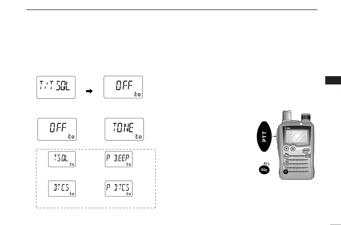
DDSetting the subaudible tone encoder ON/OFF
qWhile pushing and holding [FUNC], push and hold
[SQL] (
ATT
•
SET
)for 1 sec. to enter set mode.
wRotate [DIAL] to select “T/TSQL.”
eWhile pushing and holding [FUNC], rotate [DIAL] to select
the repeater tone from “TONE” or “OFF.”
rPush [SQL] (
ATT
•
SET
)to exit set mode.
ATT
DTCS
TSQL
WFMAM -DUP
LOWVOL PRIO P SKIP
MR
5
19
ATT
DTCS
TSQL
WFMAM -DUP
LOWVOL PRIO P SKIP
MR
5
19
ATT
DTCS
TSQL
WFMAM -DUP
LOWVOL PRIO P S K IP
MR
5
19
ATT
DTCS
TSQL
WFMAM -DUP
LOWVOL PRIO P SKIP
MR
5
19
ATT
DTCS
TSQL
WFMAM -DUP
LOW
VOL PRIO P S KI P
MR
5
19
ATT
DTCS
TSQL
WFMAM -DUP
LOW
VOL PRIO P S KI P
MR
5
19
Tone squelch with pocket
beep function selection
DTCS with pocket beep
function selection
Subaudible tone OFF
Tone squelch
selection
DTCS selection
Repeater tone selection
Tone
decoder
selections
ATT
DTCS
TSQL
WFMAM -DUP
LOW
VOL PRIO P S KI P
MR
5
19
ATT
DTCS
TSQL
WFMAM -DUP
LOW
VOL PRIO P S KI P
MR
5
19
After
1 sec.
Some European repeaters require a 1750 Hz tone burst to be
accessed. For such European repeaters, perform the follow-
ing.
qSet the receive frequency (repeater output frequency).
wSet the shift direction of the transmit frequency. (–DUP or
+DUP; see p. 19 for details.)
• “–DUP” or “+DUP” indicates a minus or plus offset of the transmit
frequency, respectively.
eWhile pushing and holding
[PTT], push and hold
[SQL] (
ATT
•
SET
)for 1 to 2
sec. to transmit a 1750 Hz
tone burst signal.
•The displayed frequency auto-
matically changes to the trans-
mit frequency (repeater input
frequency).
•If “OFF” appears, check the off-
set frequency (see next page
for details) or shift direction
(right section).
rPush and hold [PTT] to transmit.
tRelease [PTT] to receive.
yPush and hold [SQL] (
ATT
•
SET
)to monitor the repeater
input frequency.
SCAN
S.MW
SET
SET
■1750 Hz tone
23
5REPEATER OPERATION
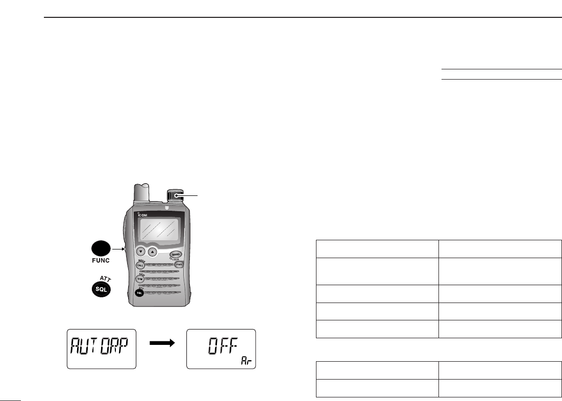
The USA/KOREA versions automatically activate the repeater
settings when the operating frequency falls within or outside
of the general repeater output frequency range. The offset
and repeater tone frequencies are not changed by the auto
repeater function. Reset these frequencies, if necessary.
qWhile pushing and holding [FUNC], push and hold
[SQL] (
ATT
•
SET
)for 1 sec. to enter set mode.
wRotate [DIAL] to select “AUTORP.”
eWhile pushing and holding [FUNC], rotate [DIAL] to select
the desired condition.
U.S.A. version:
•OFF : The auto repeater function is turned OFF.
•DUP ONLY : Activates duplex offset only. (default)
•DUP TONE : Activates duplex and tone.
Korea version:
•OFF : Deactivates the function.
•ON: Activates duplex and tone. (default)
rPush [SQL] (
ATT
•
SET
)to exit set mode.
DDFrequency range and offset direction
• U.S.A. version:
• Korea version:
ATT
DTCS
TSQL
WFMAM -DUP
LOW
VOL PRIO P S KI P
MR
5
19
ATT
DTCS
TSQL
WFMAM -DUP
LOW
VOL PRIO P SKIP
MR
5
19
After 1 sec.
Auto repeater item Setting indication
SCAN
S.MW
SET
[DIAL]
SET
■Auto repeater function USA/KOREA versions only
Frequency range Duplex direction
145.200–145.495 MHz “–” appears
146.610–146.995 MHz
147.000–147.395 MHz “+” appears
442.000–444.995 MHz “+” appears
447.000–449.995 MHz “–” appears
Frequency range Duplex direction
439.000–440.000 MHz “–” appears
24
6
MEMORY/CALL CHANNELS
■General description
The IC-P7A has 1050 memory channels including 50 scan
edge memory channels (25 pairs) for storage of often-used
frequencies. And a total of 18 memory banks, A to H, J, L, N,
O to R, T, U and Y are available for storing groups of fre-
quencies, etc. Up to 100 channels can be assigned into a
bank.
DDMemory channel contents
The following information can be programmed into memory
channels:
•Operating frequency (p. 11)
•Operating mode (p. 14)
•Duplex direction (DUP or –DUP) with an offset frequency
(pgs. 19, 20)
•Subaudible tone encoder (p. 22), tone squelch or DTCS
squelch ON/OFF (p. 45)
•Subaudible tone frequency (p. 21), tone squelch fre-
quency or DTCS code with polarity (pgs. 46, 47)
•Scan skip information (p. 39).
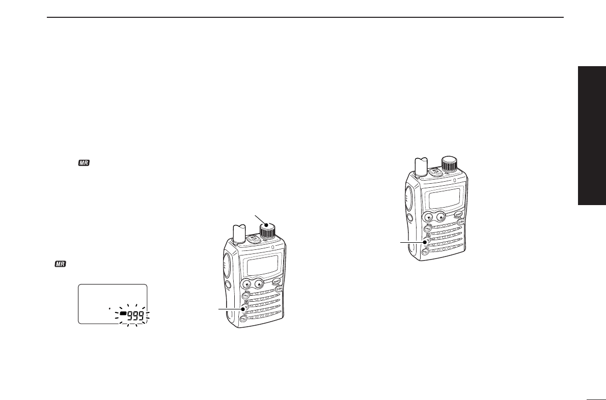
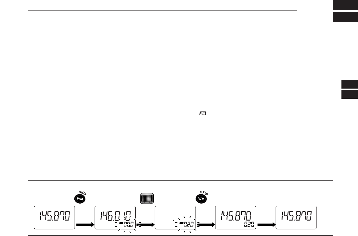
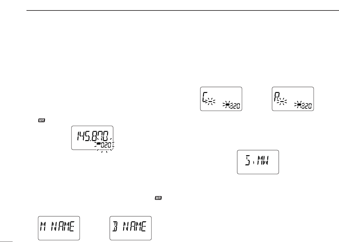
■
Memory channel programming
qPush [V/M] (
SKIP
•
S
.
MW
)to select VFO mode.
wSet the desired frequency:
➥Select the desired band with [BAND] (
TS
•
LOCK
).
➥Set the desired frequency with [DIAL].
➥Set other data (e.g. offset frequency, duplex direction, sub-
audible tone frequency, etc.), if desired.
ePush and hold [V/M] (
SKIP
•
S
.
MW
)for 1 sec. to enter select
memory write mode.
•1 short and 1 long beep sound.
•“ ” indicator and memory channel number blink.
rRotate [DIAL] to select the desired channel.
•Call channels (C0, C1), VFO (VF) and scan edge channels
(00A/00b to 24A/24b), as well as regular memory channels, can
be programmed in this way.
•While pushing and holding [FUNC], rotate [DIAL] to select mem-
ory channel in 10 channel steps.
tPush and hold [V/M] (
SKIP
•
S
.
MW
)for 1 sec.
•3 beeps sound
•Memory channel number automatically increases when contin-
uing to push [V/M] (
SKIP
•
S
.
MW
)after programming.
[EXAMPLE]: Programming 145.870 MHz into memory channel 20 (blank channel).
ATT
DTCS
TSQL
WFMAM -DUP
LOW
VOL PRIO P S KI P
MR
5
19
ATT
DTCS
TSQL
WFMAM -DUP
LOW
VOL PRIO P S KI P
MR
5
19
ATT
DTCS
TSQL
WFMAM -DUP
LOW
VOL PRIO P S KI P
MR
5
19
ATT
DTCS
TSQL
WFMAM -DUP
LOW
VOL PRIO P S KI P
MR
5
19
ATT
DTCS
TSQL
WFMAM -DUP
LOW
VOL PRIO P S KI P
MR
5
19
Push for 1 sec. Rotate
S.MW
Push for 1 sec.
S.MW
5
6
25
6MEMORY/CALL CHANNELS
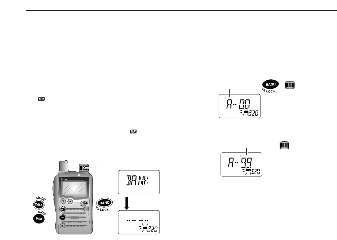
The IC-P7A has a total of 18 banks (A to H, J, L, N, O to R, T, U
and Y). Regular memory channels, 000 to 999, may assigned
into a desired bank for easy memory management.
qPush and hold [V/M] (
SKIP
•
S
.
MW
)for 1 sec. to enter select
memory write mode.
•1 short and 1 long beep sound.
•“ ” indicator and memory channel number blink.
wRotate [DIAL] to select the desired memory channel.
eWhile pushing and holding [CALL] (
MODE
•
SCAN
), rotate
[DIAL] to select “BANK.”
•After releasing [CALL] (
MODE
•
SCAN
), “-- -- -- --” is displayed in-
stead of the frequency indication, and only “ ” indicator blinks.
•Bank group and channel number is displayed if the selected
memory channel has already been assigned to a bank.
•“BANK” can can also be selected by pushing [CALL]
(
MODE
•
SCAN
)several times.
rWhile pushing and holding [BAND] (
TS
•
LOCK
), rotate
[DIAL] to select the desired bank.
•Banks A to H, J, L, N, O to R, T, U and Y are available.
•The bank can also be selected by pushing [BAND] (
TS
•
LOCK
)
several times.
tRotate [DIAL] to select the desired bank channel number.
•Vacant bank channel numbers are only be displayed.
yPush and hold [V/M] (
SKIP
•
S
.
MW
)for 1 sec. to set the chan-
nel into the bank.
•Return to the previous indication.
ATT
DTCS
TSQL
WFMAM -DUP
LOW
VOL PRIO P S KI P
MR
5
19
Bank channel is selected with
ATT
DTCS
TSQL
WFMAM -DUP
LOW
VOL PRIO P S KI P
MR
5
19
Bank is selected with
+
SCAN
S.MW
SET
ATT
DTCS
TSQL
WFMAM -DUP
LOW
VOL PRIO P S KI P
MR
5
19
ATT
DTCS
TSQL
WFMAM -DUP
LOW
VOL PRIO P S KI P
MR
5
19
S.MW
[DIAL]
After [CALL]
released
SCAN
■Memory bank setting
26
6
MEMORY/CALL CHANNELS
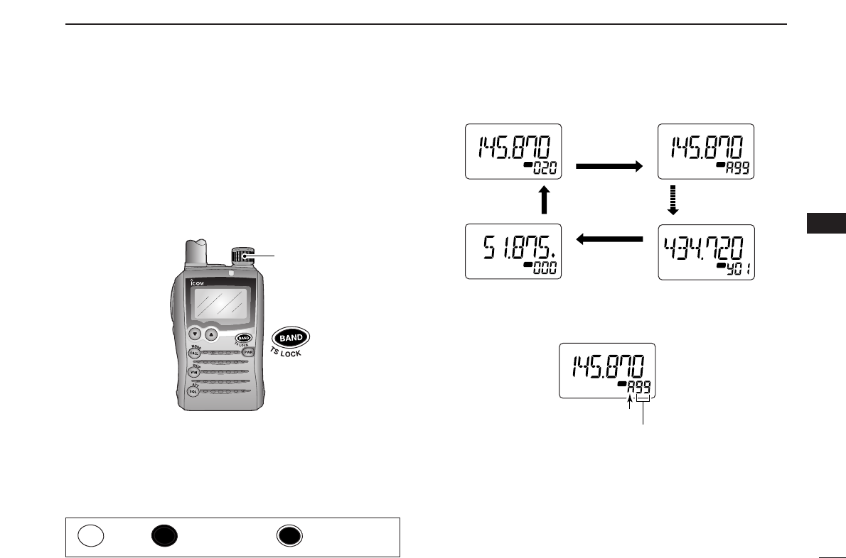
qPush [V/M] (
SKIP
•
S
.
MW
)to select memory mode, if desired.
wWhile pushing and holding [BAND] (
TS
•
LOCK
), rotate
[DIAL] to select the desired bank (A to H, J, L, N, O to R, T, U
and Y).
•The bank can also be selected by pushing [BAND] (
TS
•
LOCK
)
several times.
•The only programmed banks are displayed.
eRotate [DIAL] to select the bank channel.
•Only programmed channels are displayed.
rTo return to regular memory
operation, rotate [DIAL] while
pushing and holding
[BAND] (
TS
•
LOCK
), or push [BAND]
(
TS
•
LOCK
)several times.
ATT
DTCS
TSQL
WFMAM -DUP
LOW
VOL PRIO P S KI P
MR
5
19
Bank initial
Bank channel number
ATT
DTCS
TSQL
WFMAM -DUP
LOW
VOL PRIO P S KI P
MR
5
19
ATT
DTCS
TSQL
WFMAM -DUP
LOW
VOL PRIO P S KI P
MR
5
19
ATT
DTCS
TSQL
WFMAM -DUP
LOW
VOL PRIO P S KI P
MR
5
19
ATT
DTCS
TSQL
WFMAM -DUP
LOW
VOL PRIO P S KI P
MR
5
19
Only programmed
banks appear
Auto write channels
Rotate [DIAL] while
pushing [BAND]
SCAN
S.MW
SET
[DIAL]
■Memory bank selection
6
Push Push and hold Dual operation
27
6MEMORY/CALL CHANNELS
■Programming memory/bank name
Each memory channel can be programmed with an alphanu-
meric channel name for easy recognition and that can be indi-
cated independently by channel. Names can be a maximum of
6 characters.
qPush [V/M] (
SKIP
•
S
.
MW
)to select memory mode.
wRotate [DIAL] to select the desired memory channel.
ePush and hold [V/M] (
SKIP
•
S
.
MW
)for 1 sec. to enter select
memory write mode.
•1 short and 1 long beep sound.
•“ ” indicator and memory channel number blink.
rWhile pushing and holding [CALL] (
MODE
•
SCAN
), rotate
[DIAL] to select “M NAME” or “B NAME” when program-
ming the memory name or the bank name, respectively.
•Name type can also be selected by pushing [CALL]
(
MODE
•
SCAN
)several times.
•After releasing [CALL] (
MODE
•
SCAN
), an under bar blinks for the
first digit instead of the frequency indication, and only “ ” indi-
cator blinks.
tWhile pushing and holding [FUNC], rotate [DIAL] to select
the desired character.
•The selected character blinks.
yRotate [DIAL] to move the cursor to left or right.
uRepeat steps tand yuntil the desired 6-character chan-
nel names are displayed.
iPush [CALL] (
MODE
•
SCAN
)several times, or rotate [DIAL]
while pushing and holding [CALL] (
MODE
•
SCAN
)to select
“S.MW.”
oPush and hold [V/M] (
SKIP
•
S
.
MW
)for 1 sec. to program the
name and exit the channel name programming.
•3 beeps sound.
•Available characters
Ato Z, 0 to 9, (, ), ✱, +, –, ., /, :, =and space.
ATT
DTCS
TSQL
WFMAM -DUP
LOW
VOL PRIO P S KI P
MR
5
19
ATT
DTCS
TSQL
WFMAM -DUP
LOW
VOL PRIO P S KI P
MR
5
19
ATT
DTCS
TSQL
WFMAM -DUP
LOW
VOL PRIO P S KI P
MR
5
19
Bank nameMemory name
ATT
DTCS
TSQL
WFMAM -DUP
LOW
VOL PRIO P S KI P
MR
5
19
ATT
DTCS
TSQL
WFMAM -DUP
LOW
VOL PRIO P S KI P
MR
5
19
Bank name selectionMemory name selection
ATT
DTCS
TSQL
WFMAM -DUP
LOW
VOL PRIO P SKIP
MR
5
19
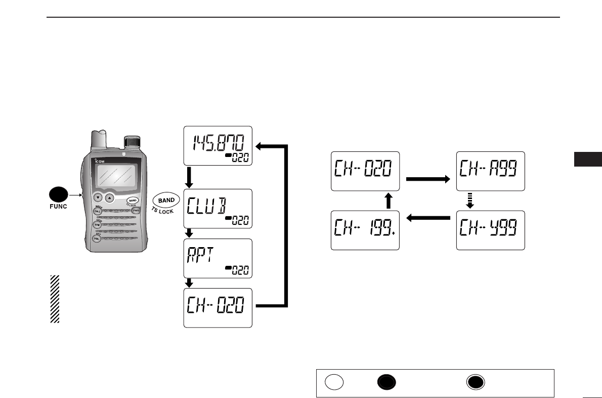
28
6
MEMORY/CALL CHANNELS
During memory mode operation, the programmed memory
name, bank name or the channel number can be displayed
instead of the frequency at your preference.
qPush [V/M] (
SKIP
•
S
.
MW
)to select memory mode.
•[BAND] (
TS
•
LOCK
)to select the desired bank.
wWhile pushing and holding [FUNC], push [BAND]
(
TS
•
LOCK
)momentarily to select display type from fre-
quency, bank name, memory name and channel number
display.
DDSelecting bank channel indication
During bank channel operation, the bank channel number can
also be displayed instead of the memory channel number in-
dication.
➥After selecting channel number indication as described at
left, push [BAND] (
TS
•
LOCK
)to select the desired bank.
Or while pushing and holding [BAND] (
TS
•
LOCK
), rotate
[DIAL] to select the desired bank.
ATT
DTCS
TSQL
WFMAM -DUP
LOW
VOL PRIO P S KI P
MR
5
19
ATT
DTCS
TSQL
WFMAM -DUP
LOW
VOL PRIO P S KI P
MR
5
19
ATT
DTCS
TSQL
WFMAM -DUP
LOW
VOL PRIO P S KI P
MR
5
19
ATT
DTCS
TSQL
WFMAM -DUP
LOW
VOL PRIO P S KI P
MR
5
19
Push [BAND]
Memory channel No. indication Bank channel No. indication
Bank channel No. indicationAuto write channel No.
SCAN
S.MW
SET
ATT
DTCS
TSQL
WFMAM -DUP
LOW
VOL PRIO P S KI P
MR
5
19
ATT
DTCS
TSQL
WFMAM -DUP
LOW
VOL PRIO P S KI P
MR
5
19
ATT
DTCS
TSQL
WFMAM -DUP
LOW
VOL PRIO P S KI P
MR
5
19
ATT
DTCS
TSQL
WFMAM -DUP
LOW
VOL PRIO P S KI P
MR
5
19
When no memory or bank
name is programmed with the
selected memory channel,
frequency is displayed on the
function display.
Push [BAND] momentarily
while pushing [FUNC]
■Selecting display type
6
Push Push and hold Dual operation
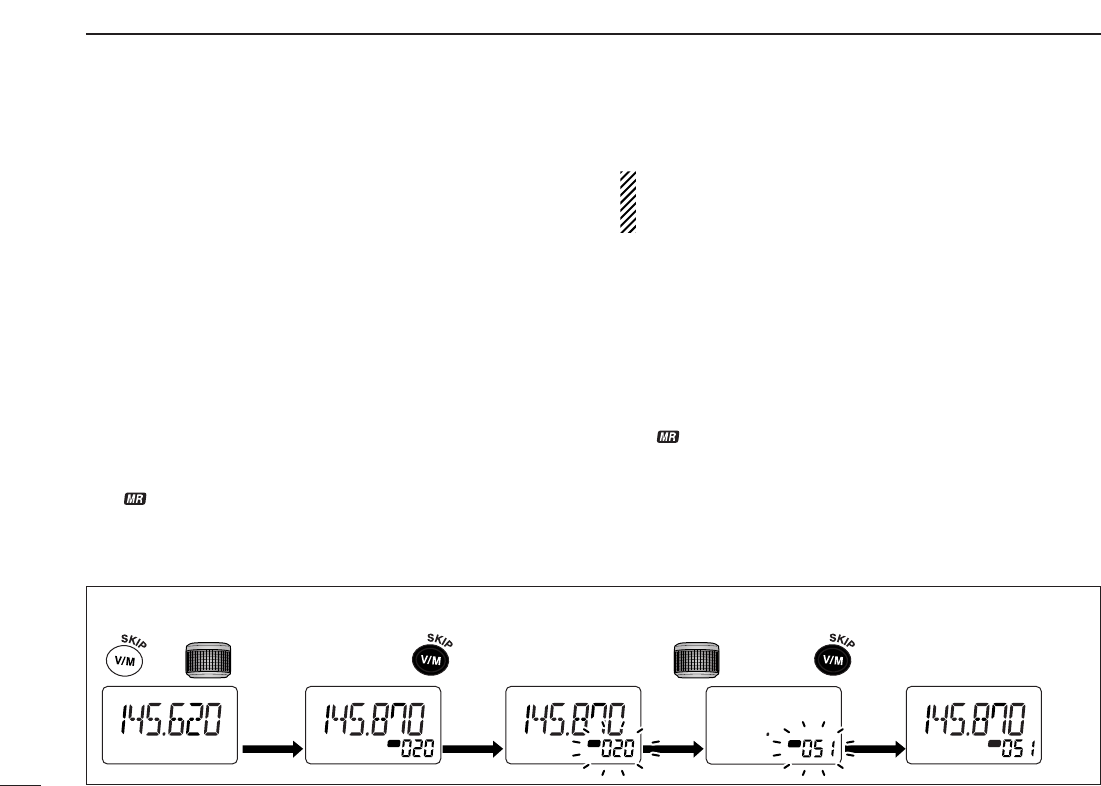
29
6MEMORY/CALL CHANNELS
This function transfers a memory channel’s contents to a VFO
(or another memory channel). This is useful when searching
for signals around a memory channel frequency and for re-
calling the offset frequency, subaudible tone frequency etc.
DMemory➪VFO
qSelect the memory channel to be copied.
➥Push [V/M] (
SKIP
•
S
.
MW
)momentarily to select memory
mode, then rotate [DIAL] to select the desired memory
channel.
•Select the bank channel with [BAND] (
TS
•
LOCK
)and [DIAL],
if desired.
wPush and hold [V/M] (
SKIP
•
S
.
MW
)for 1 sec. to enter select
memory write mode.
•1 short and 1 long beep sound.
•“ ” indicator and memory channel number blink.
eRotate [DIAL] to select “VF.”
rPush and hold [V/M] (
SKIP
•
S
.
MW
)for 1 sec. again.
•VFO mode is selected automatically.
Pushing and holding [V/M] (
SKIP
•
S
.
MW
)for 2 sec. at the
step w, can also copies the memory contents to VFO. In
this case, steps eand rare not necessary.
DMemory➪memory
qSelect the memory channel to be transferred.
➥
Push
[V/M] (
SKIP
•
S
.
MW
)
to select memory mode, then ro-
tate [DIAL] to select the desired memory channel.
wPush and hold [V/M] (
SKIP
•
S
.
MW
)for 1 sec. to enter select
memory write mode.
•1 short and 1 long beep sound.
•“ ” indicator and memory channel number blink.
•Do not hold [V/M] (
SKIP
•
S
.
MW
)for more than 1 sec. otherwise the
memory contents will be copied to VFO.
eRotate [DIAL] to select the target memory channel.
rPush and hold [V/M] (
SKIP
•
S
.
MW
)for 1 sec. again to trans-
fer.
[EXAMPLE]: Copying channel 20 to 51.
ATT
DTCS
TSQL
WFMAM -DUP
LOW
VOL PRIO P SKIP
MR
5
19
ATT
DTCS
TSQL
WFMAM -DUP
LOW
VOL PRIO P S KI P
MR
5
19
ATT
DTCS
TSQL
WFMAM -DUP
LOW
VOL PRIO P S KI P
MR
5
19
ATT
DTCS
TSQL
WFMAM -DUP
LOW
VOL PRIO P S KI P
MR
5
19
ATT
DTCS
TSQL
WFMAM -DUP
LOW
VOL PRIO P S KI P
MR
5
19
S.MW
Push for 1 sec. Rotate
S.MW
Push for 1 sec.
S.MW
Select memory channel
■
Copying memory contents
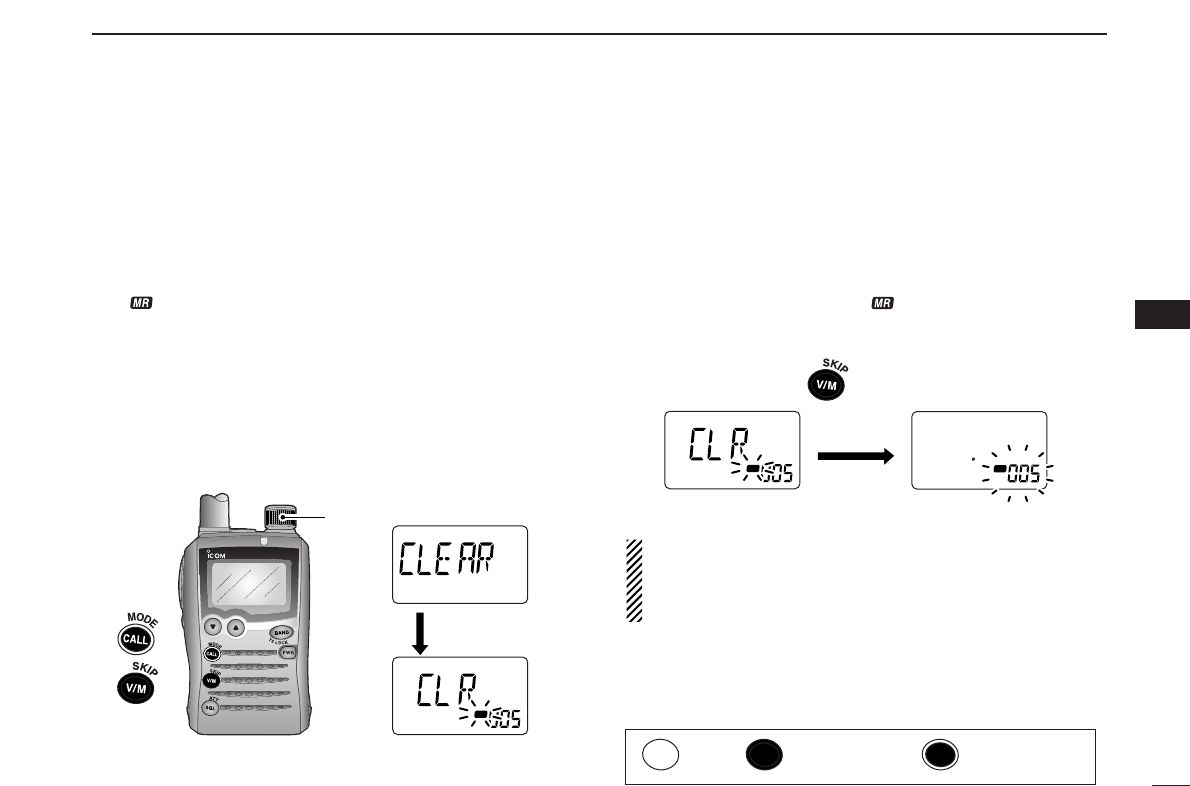
30
6
MEMORY/CALL CHANNELS
Contents of programmed memories can be cleared (blanked),
if desired.
qPush and hold [V/M] (
SKIP
•
S
.
MW
)for 1 sec. to enter select
memory write mode.
•1 short and 1 long beeps sound.
•“ ” indicator and memory channel number blink.
•Do not hold [V/M] (
SKIP
•
S
.
MW
)for more than 2 sec. otherwise the
memory contents will be copied to VFO.
wRotate [DIAL] to select the desired memory channel to be
cleared.
eWhile pushing and holding [CALL] (
MODE
•
SCAN
), rotate
[DIAL] to select “CLEAR.”
•“CLEAR” item can also be selected by pushing [CALL]
(
MODE
•
SCAN
)several times.
rPush and hold [V/M] (
SKIP
•
S
.
MW
)for 1 sec. to clear the
contents.
•3 beeps sound.
•Return to VFO or memory mode, if VFO is selected before per-
forming step q.
•Return to select memory write mode if memory mode is selected
before performing step q.— “ ” indicator and memory chan-
nel number blink. Push [V/M] (
SKIP
•
S
.
MW
)momentarily to return
to memory mode.
While pushing and holding [FUNC], push and hold
[V/M] (
SKIP
•
S
.
MW
)for 1 sec. after step walso clears the
memory contents. In this case, steps eand rare not
necessary.
☞NOTE: Be careful!— the contents of cleared memories
CANNOT be re-called even in bank channel opera-
tion.
ATT
DTCS
TSQL
WFMAM -DUP
LOW
VOL PRIO P S KI P
MR
5
19
ATT
DTCS
TSQL
WFMAM -DUP
LOW
VOL PRIO P S KI P
MR
5
19
Push for 1 sec.
S.MW
SCAN
S.MW
SET
ATT
DTCS
TSQL
WFMAM -DUP
LOW
VOL PRIO P S KI P
MR
5
19
ATT
DTCS
TSQL
WFMAM -DUP
LOW
VOL PRIO P S KI P
MR
5
19
SCAN
S.MW
[DIAL]
After [CALL]
released
■Memory clearing
6
Push Push and hold Dual operation