ICOM orporated 286900 VHF/UHF Dual Band FM Transceiver User Manual IC P7A
ICOM Incorporated VHF/UHF Dual Band FM Transceiver IC P7A
Contents
- 1. Users Manual 1
- 2. Users Manual 2
Users Manual 2
31
6MEMORY/CALL CHANNELS
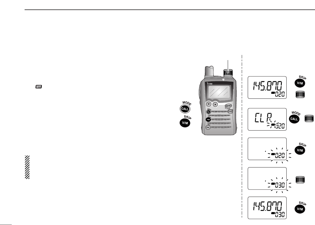
Contents of programmed memory channels can be trans-
ferred to another memory channels.
qPush and hold [V/M] (
SKIP
•
S
.
MW
)for 1 sec. to enter select
memory write mode.
•1 short and 1 long beeps sound.
•“ ” indicator and memory channel number blink.
•Do not hold [V/M] (
SKIP
•
S
.
MW
)for more than 2 sec. otherwise the
memory contents will be copied to VFO.
wRotate [DIAL] to select the desired memory channel to be
transferred.
eWhile pushing and holding [CALL] (
MODE
•
SCAN
), rotate
[DIAL] to select “CLEAR.”
•Pushing [CALL] (
MODE
•
SCAN
)several times also “CLEAR” item
is selectable.
rPush and hold [V/M] (
SKIP
•
S
.
MW
)for 1 sec.
•The displayed contents are cleared.
CONVENIENT!:
Instead of steps eand roperations, while pushing and
holding [FUNC], push and hold [V/M] (
SKIP
•
S
.
MW
)for 1
sec. also clearing the contents.
tRotate [DIAL] to select the desired target memory chan-
nel.
yPush and hold [V/M] (
SKIP
•
S
.
MW
)for 1 sec. to transfer the
contents.
SCAN
S.MW
ATT
DTCS
TSQL
WFMAM -DUP
LOW
VOL PRIO P SK IP
MR
5
19
ATT
DTCS
TSQL
WFMAM -DUP
LOW
VOL PRIO P SK IP
MR
5
19
ATT
DTCS
TSQL
WFMAM -DUP
LOW
VOL PRIO P SK IP
MR
5
19
ATT
DTCS
TSQL
WFMAM -DUP
LOW
VOL PRIO P SK IP
MR
5
19
ATT
DTCS
TSQL
WFMAM -DUP
LOW
VOL PRIO P SK IP
MR
5
19
Steps q and w
Step e
Step r
Step t
Step y
[DIAL]
SCAN
S.MW
• Example— Transferring
the contents of memory
channel 20 to channel 30.
+
S.MW
S.MW
S.MW
SCANSCAN
SET
■
Transferring memory contents

32
6
MEMORY/CALL CHANNELS
■Erasing/transferring bank contents
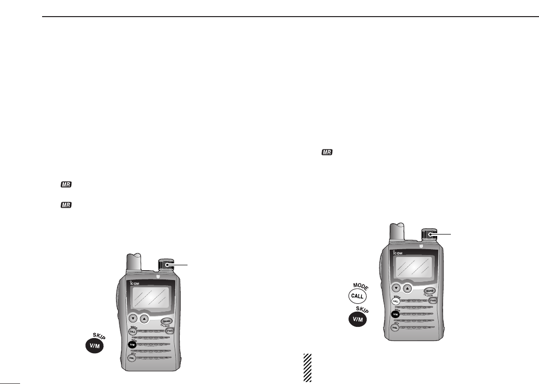
The bank contents of programmed memory channels can be
cleared or reassigned to another memory bank.
INFORMATION: Even if the memory bank contents are
cleared, the memory channel contents still remain pro-
grammed.
qSelect the desired bank contents to be transferred or
erased from the bank.
➥Push [V/M] (
SKIP
•
S
.
MW
)to select memory mode.
➥While pushing and holding [BAND] (
TS
•
LOCK
), rotate
[DIAL] to select the desired memory bank.
➥Rotate [DIAL] to select the bank channel.
wPush and hold [V/M] (
SKIP
•
S
.
MW
)for 1 sec. to enter select
memory write mode.
•1 short and 1 long beeps sound.
•Displays the original memory channel number automatically and
“” indicator and memory channel number blink.
•Do not hold [V/M] (
SKIP
•
S
.
MW
)for more than 2 sec. otherwise the
bank contents will be copied to VFO.
eWhile pushing and holding [CALL] (
MODE
•
SCAN
), rotate
[DIAL] to select “BANK.”
•Pushing [CALL] (
MODE
•
SCAN
)several times, “BANK” is also se-
lectable.
rWhile pushing and holding [BAND] (
TS
•
LOCK
), rotate
[DIAL] to select the desired bank to receive the transferred
information or erase the bank contents.
•Select “-- -- -- --” indication when erasing the contents from the
bank.
tRotate [DIAL] to select the desired bank channel.
yWhile pushing and holding [CALL] (
MODE
•
SCAN
), rotate
[DIAL] to select “S.MW.”
•Pushing [CALL] (
MODE
•
SCAN
)several times, “S.MW” is also se-
lectable.
uPush and hold [V/M] (
SKIP
•
S
.
MW
)for 1 sec.
•3 beeps sound.
ATT
DTCS
TSQL
WFMAM -DUP
LOW
VOL PRIO P SK IP
MR
5
19
ATT
DTCS
TSQL
WFMAM -DUP
LOW
VOL PRIO P SK IP
MR
5
19
When transferring When erasing
ATT
DTCS
TSQL
WFMAM -DUP
LOW
VOL PRIO P SK IP
MR
5
19
ATT
DTCS
TSQL
WFMAM -DUP
LOW
VOL PRIO P SKIP
MR
5
19
Push for 1 sec.
S.MW
6
Push Push and hold Dual operation
33
6MEMORY/CALL CHANNELS
■
Call channel programming
qPush [V/M] (
SKIP
•
S
.
MW
)to select VFO mode, if necessary.
wSet the desired frequency:
➥Select the desired band with [BAND] (
TS
•
LOCK
).
➥Set the desired frequency with [DIAL].
➥Set other data (e.g. offset frequency, duplex direction, sub-
audible tone frequency, etc.), if desired.
ePush and hold [V/M] (
SKIP
•
S
.
MW
)for 1 sec. to enter select
memory write mode.
•1 short and 1 long beep sound.
•“ ” indicator and memory channel number blink.
rRotate [DIAL] to select the desired call channel.
•“ ” indicator and call channel number “C0” or “C1” blink.
•While pushing and holding [FUNC], rotate [DIAL] to select mem-
ory channel in 10 channel steps.
tPush and hold [V/M] (
SKIP
•
S
.
MW
)for 1 sec.
•3 beeps sound
■
Copying call channel contents
qPush [CALL] (
MODE
•
SCAN
)momentarily to select a call
channel.
wRotate [DIAL] to select the desired call channel.
ePush and hold [V/M] (
SKIP
•
S
.
MW
)for 1 sec. to enter select
memory write mode.
•1 short and 1 long beeps sound.
•“ ” indicator and memory channel number blink.
•Do not hold [V/M] (
SKIP
•
S
.
MW
)for more than 2 sec. otherwise the
call channel contents will be copied to VFO.
rRotate [DIAL] to select the desired target memory chan-
nel.
tPush and hold [V/M] (
SKIP
•
S
.
MW
)for 1 sec. to transfer the
contents.
CONVENIENT!:
When you want to copy the call channel contents to the VFO,
push and hold [V/M] (
SKIP
•
S
.
MW
)for 2 sec. as in steps e.
SCAN
S.MW
SET
SCAN
[DIAL]
S.MW
SCAN
S.MW
SET
[DIAL]
S.MW
34
7
SCAN OPERATION
6
7
Scanning searches for signals automatically and makes it
easier to locate new stations for contact or listening purposes.
There are 7 scan types and 4 resume conditions to suit your
operating needs.
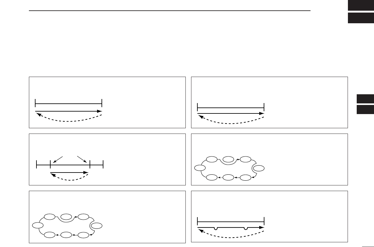
FULL SCAN (p. 35) Repeatedly scans all frequen-
cies over all bands.
Some frequency ranges are
not scanned according to the
frequency coverage of the
transceiver’s version.
495
kHz 999.990
MHz
Scan
Jump
SELECTED BAND SCAN
(p. 35)
Repeatedly scans all frequen-
cies over the entire selected
band.
Band
edge Band
edge
Scan
Jump
ALL/SELECTED BANK
SCAN (p. 37)
Repeatedly scans all bank
channels or selected bank
channels. Skip scan is also
available.
SKIP
SKIP
A99 A03
A00 A01 A02
A04
A98
A05
FREQUENCY/MEMORY
SKIP FUNCTION (p. 39)
Skips unwanted frequencies
or channels that inconve-
niently stop scanning. This
function can be turned ON
and OFF by pushing [FUNC]
+ [V/M] (
SKIP
•
S
.
MW
)in either
VFO or memory mode.
Band
edge Band
edge
Scan
SKIP SKIP
Jump
PROGRAMMED SCAN
(p. 35)
Repeatedly scans between
two user-programmed fre-
quencies. Used for checking
for frequencies within a speci-
fied range such as repeater
output frequencies, etc.
Band
edge xxA xxb
Band
edge
Scan edges
Scan
Jump
MEMORY (SKIP) SCAN
(p. 37)
Repeatedly scans memory
channels except those set as
skip channels. Skip channels
can be turned ON and OFF
by pushing [FUNC] + [V/M]
(
SKIP
•
S
.
MW
)in memory mode.
SKIP
SKIP
M 0 M 4
M 1 M 2 M 3
M 5
M 199
M 6
■Scan types
qSelect VFO mode with [V/M] (
SKIP
•
S
.
MW
), if necessary.
•Select the desired frequency band with [BAND] (
TS
•
LOCK
), if de-
sired.
wSet the squelch to the point where noise is just muted.
ePush and hold [CALL] (
MODE
•
SCAN
)for 1 sec. to enter
scan type selection condition.
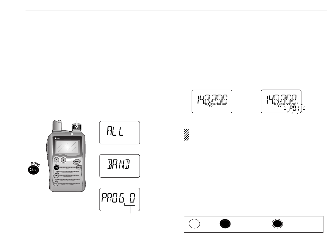
rRotate [DIAL] to select the desired scanning type.
•“ALL” for full scan; “BAND” for band scan, “PROGxx” for pro-
grammed scan (xx= 0 to 24; programmed scan edges numbers
only displayed)
tPush [CALL] (
MODE
•
SCAN
)again to start the scan
•Scan pauses when a signal is received.
•Rotate [DIAL] to change the scanning direction, or resumes
manually.
•To stop the scan, push [CALL] (
MODE
•
SCAN
).
About the scanning steps: The selected tuning step in
each frequency band (in VFO mode) is used during scan.
ATT
DTCS
TSQL
WFMAM -DUP
LOW
VOL PRIO P SK IP
MR
5
19
ATT
DTCS
TSQL
WFMAM -DUP
LOW
VOL PRIO P SK IP
MR
5
19
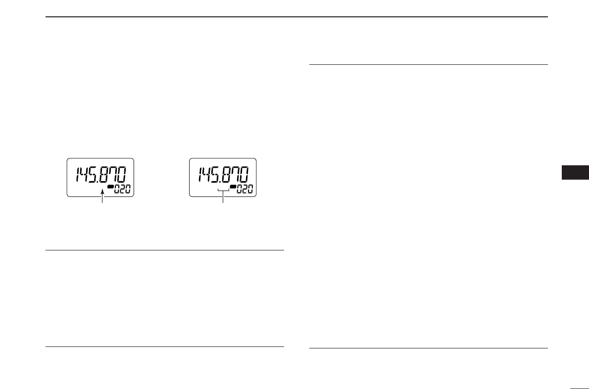
• During full/band scan • During programmed scan
SCAN
S.MW
SET
ATT
DTCS
TSQL
WFMAM -DUP
LOW
VOL PRIO P SKIP
MR
5
19
ATT
DTCS
TSQL
WFMAM -DUP
LOW
VOL PRIO P SK IP
MR
5
19
ATT
DTCS
TSQL
WFMAM -DUP
LOW
VOL PRIO P SK IP
MR
5
19
• Full scan selection
• Band scan selection
• Programmed scan selection
Selectable between “ 0” to “24”
if programmed
SCAN
[DIAL]
■Full/band/programmed scan
35
7SCAN OPERATION
Push Push and hold Dual operation
36
7
SCAN OPERATION
7
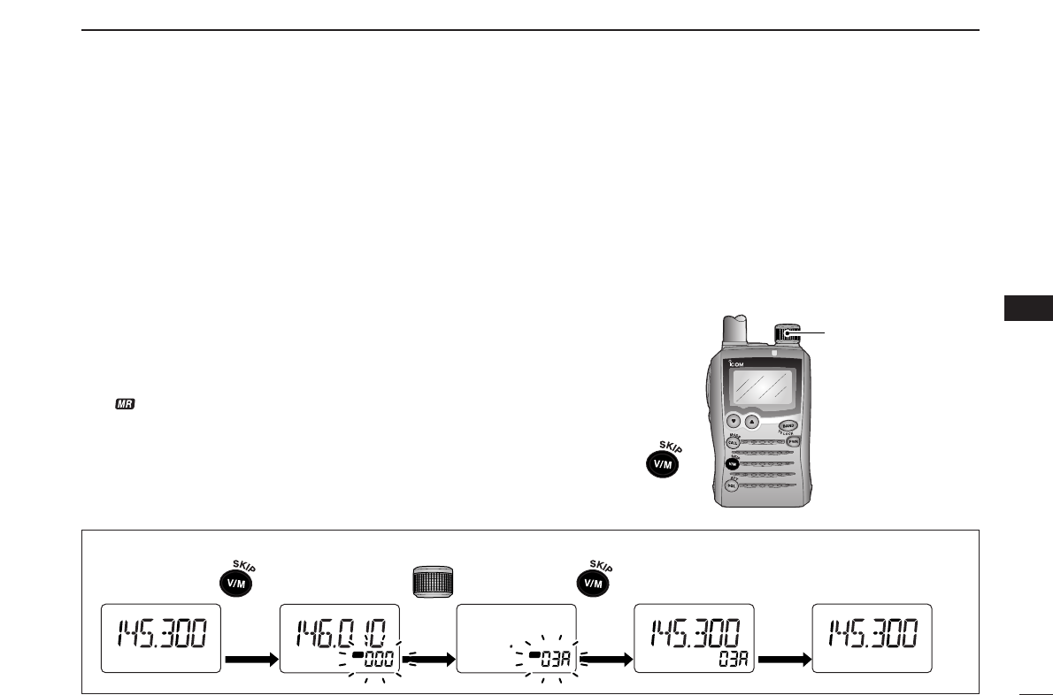
Scan edges can be programmed in the same manner as
memory channels. Scan edge frequencies are programmed
into scan edges, 00A/00b to 24A/24b, in memory channels.
qPush [V/M] (
SKIP
•
S
.
MW
)to select VFO mode, if necessary.
wSet the desired frequency:
➥Select the desired band with [BAND] (
TS
•
LOCK
).
➥Set the desired frequency with [DIAL].
➥Set other data (e.g. offset frequency, duplex direction, sub-
audible tone frequency, etc.), if desired.
ePush and hold [V/M] (
SKIP
•
S
.
MW
)for 1 sec. to enter select
memory write mode.
•1 short and 1 long beeps sound.
•“ ” indicator and memory channel number blink.
rRotate [DIAL] to select the desired programmed scan
edge channel from 00A to 24A.
tPush and hold [V/M] (
SKIP
•
S
.
MW
)for 1 sec.
•3 beeps sound
•The other scan edge channel “b,” 00b to 24b, is automatically
selected when continuing to push [V/M] (
SKIP
•
S
.
MW
)after pro-
gramming.
yTo program a frequency for the other pair of scan edges,
00b or 24b, repeat steps wand t.
•If the same frequency is programmed into a pair of scan edges,
programmed scan will not function.
SCAN
S.MW
SET
S.MW
[DIAL]
[EXAMPLE]: Programming 145.300 MHz into scan edge 03A.
ATT
DTCS
TSQL
WFMAM -DUP
LOW
VOL PRIO P SK I P
MR
5
19
ATT
DTCS
TSQL
WFMAM -DUP
LOW
VOL PRIO P SK IP
MR
5
19
ATT
DTCS
TSQL
WFMAM -DUP
LOW
VOL PRIO P SK IP
MR
5
19
ATT
DTCS
TSQL
WFMAM -DUP
LOW
VOL PRIO P SK IP
MR
5
19
ATT
DTCS
TSQL
WFMAM -DUP
LOW
VOL PRIO P SK IP
MR
5
19
Push for 1 sec. Rotate
S.MW
Push for 1 sec.
S.MW
■Scan edges programming
37
7SCAN OPERATION
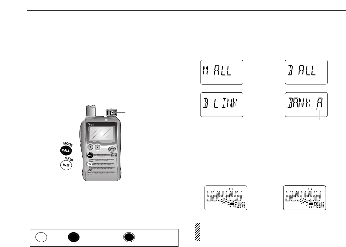
qSelect memory mode with [V/M] (
SKIP
•
S
.
MW
).
wSet the squelch to the point where noise is just muted.
ePush and hold [CALL] (
MODE
•
SCAN
)for 1 sec. to enter
scan type selection mode.
rRotate [DIAL] to select the desired scanning type.
•“M ALL” for all memory scan; “B ALL” for all bank scan; “B LINK”
for bank link scan; “BANK” for bank scan.
tPush [CALL] (
MODE
•
SCAN
)momentarily to start the se-
lected scan.
•Scan pauses when a signal is received.
•Rotate [DIAL] to change the scanning direction, or resumes
manually.
yTo stop the scan, push [CALL] (
MODE
•
SCAN
).
IMPORTANT!: To perform memory or bank scan, 2 or
more memory/bank channels MUST be programmed, oth-
erwise the scan never starts.
FM AM DUP SQL DTCSTW
FM AM DUP SQL DTCSTW
ATT
DTCS
T SQL
WFMAM -DUP
LOW
VOL PRIO P SK IP
MR
5
19
ATT
DTCS
T SQL
WFMAM -DUP
LOW
VOL PRIO P SK IP
MR
5
19
• During all memory/all bank/
bank link scan • During bank scan
FM AM DUP SQL DTCSTW
FM AM DUP SQL DTCSTW
ATT
DTCS
TSQL
WFMAM -DUP
LOW
VOL PRIO P SK IP
MR
5
19
ATT
DTCS
TSQL
WFMAM -DUP
LOW
VOL PRIO P SK IP
MR
5
19
ATT
DTCS
TSQL
WFMAM -DUP
LOW
VOL PRIO P SK IP
MR
5
19
ATT
DTCS
TSQL
WFMAM -DUP
LOW
VOL PRIO P SK IP
MR
5
19
• All memory scan selection • All bank scan selection
• Bank link scan selection • Bank scan selection
Programmed bank
SCAN
S.MW
SET
SCAN
[DIAL]
S.MW
■Memory/bank scan
Push Push and hold Dual operation
38
7
SCAN OPERATION
7
■Auto memory write scan
This scan is useful for searching a specified frequency range
and automatically storing busy frequencies into memory
channels. The same frequency ranges used for program scan
are used for auto memory write scan.
qSelect VFO mode with [V/M] (
SKIP
•
S
.
MW
), if necessary.
wPush and hold [CALL] (
MODE
•
SCAN
)for 1 sec. to enter
scan type selection condition.
eRotate [DIAL] to select the desired scanning type.
•“ALL” for full scan; “BAND” for band scan, “PROGxx” for pro-
grammed scan (xx= 0 to 24; programmed scan edges numbers
only displayed)
rPush [CALL] (
MODE
•
SCAN
)to start the scan.
tPush [V/M] (
SKIP
•
S
.
MW
)to toggle the automatic memory
write function ON and OFF.
•“ ” indicator blinks during auto memory write.
yPush [CALL] (
MODE
•
SCAN
)to stop scan.
DDDuring auto-memory write scanning:
•When a signal is received, scan pauses and the frequency
is stored into auto memory write channel group (000♦–199♦).
-2 short beeps sound when stored.
•Scan resumes after frequency storing.
•When all channels are stored, the scan cancels automati-
cally and 1 long beep sounds.
DDRe-calling the stored frequencies:
qPush [V/M] (
SKIP
•
S
.
MW
)to select memory mode.
wPush [BAND] (
TS
•
LOCK
)several times, or while pushing
and holding [BAND] (
TS
•
LOCK
), rotate [DIAL] to select the
auto memory write channel group.
•“♦” appears.
eRotate [DIAL] to select the desired channel.
DDClearing the stored frequencies:
qSelect the auto memory write channel group.
wWhile pushing and holding [FUNC], push and hold
[V/M] (
SKIP
•
S
.
MW
)for 1 sec. to clear the all channels con-
tents.
•1 short and 1 long beeps sound.
NOTE: The auto memory write channel contents CANNOT
be cleared as an independent channel. Thus it is a good
idea to copy the contents into a memory channel.
ATT
DTCS
TSQL
WFMAM -DUP
LOW
VOL PRIO P SK IP
MR
5
19
Appears
SCAN
S.MW
SET
ATT
DTCS
TSQL
WFMAM -DUP
LOW
VOL PRIO P SK IP
MR
5
19
SCAN
[DIAL]
“ ” indicator blinks
39
7SCAN OPERATION
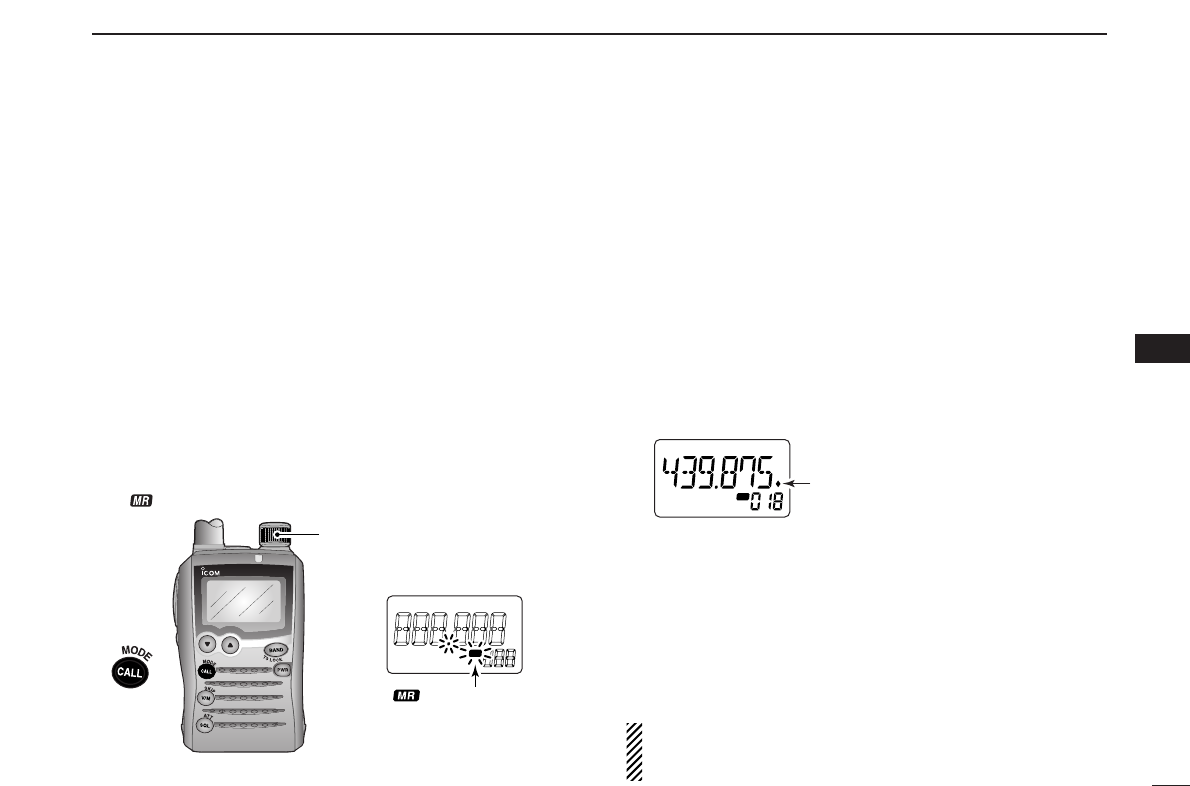
You can set the selected memory channel as a skip channel
which is skipped during memory skip scan. In addition, it can
be set as a skip channel for both memory skip scan and fre-
quency skip scan. These are useful to speed up the scan in-
terval.
qSelect a memory channel:
➥Push [V/M] (
SKIP
•
S
.
MW
)to select memory mode.
➥Rotate [DIAL] to select the desired channel to be a skip
channel/frequency.
wPush and hold [V/M] (
SKIP
•
S
.
MW
)for 1 sec. to enter select
memory write mode.
ePush [CALL] (
MODE
•
SCAN
)several times to select “SKIP.”
•While pushing and holding [CALL] (
MODE
•
SCAN
), rotating [DIAL]
can also select “SKIP.”
rRotate [DIAL] to select the skip condition from “SKIP,”
“PSKIP” or “OFF” for the selected channel.
•OFF : The channel or programmed frequency is scanned dur-
ing any scan.
•SKIP : The channel is skipped during memory or bank scan.
•PSKIP : The channel is skipped during memory/bank scan and
the programmed frequency is skipped during VFO scan,
such as programmed scan.
SCAN
S.MW
SET
ATT
DTCS
TSQL
WFMAM -DUP
LOW
VOL PRIO P SK IP
MR
5
19
ATT
DTCS
TSQL
WFMAM -DUP
LOW
VOL PRIO P SK IP
MR
5
19
• Skip setting
SCAN
After 1 sec.
Setting indication
[DIAL]
SCAN
S.MW
SET
ATT
DTCS
TSQL
WFMAM -DUP
LOW
VOL PRIO PSKIP
MR
5
19
S.MW
[DIAL]
■Skip channel/frequency setting
Push Push and hold Dual operation
40
7
SCAN OPERATION
7
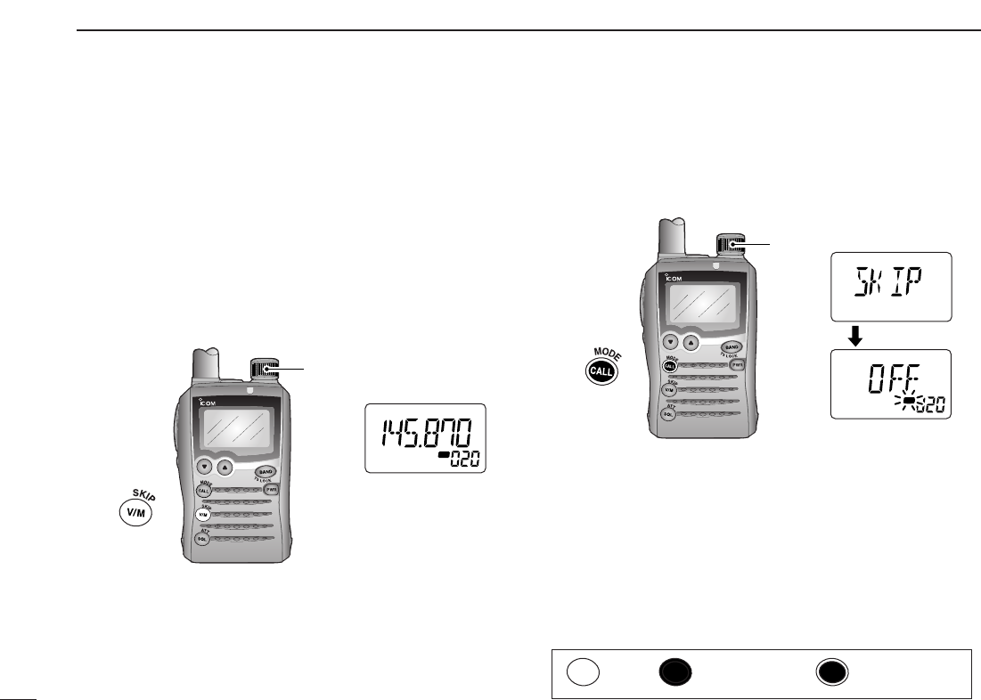
tPush [CALL] (
MODE
•
SCAN
)several times; or while pushing
and holding [CALL] (
MODE
•
SCAN
), rotate [DIAL] to select
“S.MW.”
yPush and hold [V/M] (
SKIP
•
S
.
MW
)for 1 sec. to set the skip
condition.
•“SKIP” or “PSKIP” indicator appears, according to the skip se-
lection in step r.
✔
CONVENIENT!
The skip setting can also be easily set with the following op-
eration.
qSelect the desired memory channel to be set as a skip
channel/frequency.
wWhile pushing and holding [FUNC], push [V/M]
(
SKIP
•
S
.
MW
)momentarily to select the skip condition from
“SKIP,” “PSKIP” and “OFF (no indication).”
✔
CONVENIENT!
During VFO scanning, such as programmed scan, the skip
setting can be programmed into the highest blank memory
channel which is automatically selected with the following op-
eration.
qStart the VFO scan.
➥Select VFO mode with [V/M] (
SKIP
•
S
.
MW
).
•Select the desired frequency band with [BAND] (
TS
•
LOCK
), if
desired.
➥ Push and hold [CALL] (
MODE
•
SCAN
)for 1 sec. to enter
scan type selection condition.
➥Rotate [DIAL] to select the desired scanning type.
•“ALL” for full scan; “BAND” for band scan, “PROGxx” for pro-
grammed scan (xx= 0 to 24; programmed scan edges num-
bers only displayed)
➥ Push [CALL] (
MODE
•
SCAN
)again to start the scan.
•Scan pauses when a signal is received.
•Rotate [DIAL] to change the scanning direction, or resumes
manually.
wWhen scan pauses and you want to set the paused fre-
quency as a skip frequency.
➥ Push and hold [FUNC] then push [V/M] (
SKIP
•
S
.
MW
)for
1 sec. to store the paused frequency into the highest
blank memory channel.
•While pushing and holding [FUNC], scan pauses; and after
writing the frequency, scan resumes.
ATT
DTCS
TSQL
WFMAM -DUP
LOW
VOL PRIO PSKIP
MR
5
19
ATT
DTCS
TSQL
WFMAM -DUP
LOW
VOL PRIO PSKIP
MR
5
19
• Skip channel setting • Program skip setting
“SKIP”
appears
“PSKIP”
appears
41
7SCAN OPERATION
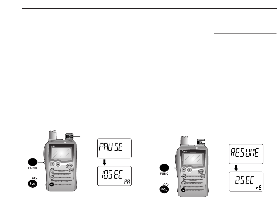
DDScan pause timer
The scan pauses when receiving signals according to the
scan pause time. It can be set from 2–20 sec. or unlimited.
qWhile pushing and holding [FUNC], push and hold
[SQL] (
ATT
•
SET
)for 1 sec. to enter set mode.
wRotate [DIAL] to select “EXPAND.”
eWhile pushing and holding [FUNC], rotate [DIAL] to turn
the expanded set mode ON.
rRotate [DIAL] to select “PAUSE.”
tWhile pushing and holding [FUNC], rotate [DIAL] to set the
desired scan pausing time from 2–20 sec. (2 sec. steps) or
“HOLD.”
•“2SEC”–“20SEC”; scan pauses 2–20 sec. while receiving a signal.
•“HOLD”; scan pauses on a received a signal until it disappears.
yPush [SQL] (
ATT
•
SET
)to exit set mode.
DDScan resume timer
The scan re-starts after a signal disappears according to the
resume time. it can be set from 0–5 sec. or unlimited.
qWhile pushing and holding [FUNC], push and hold
[SQL] (
ATT
•
SET
)for 1 sec. to enter set mode.
wRotate [DIAL] to select “EXPAND.”
eWhile pushing and holding [FUNC], rotate [DIAL] to turn
the expanded set mode ON.
rRotate [DIAL] to select “RESUME.”
tWhile pushing and holding [FUNC], rotate [DIAL] to set the
desired scan pause time from 0–5 sec. (1 sec. steps) or
“HOLD.”
•“0SEC”; scan restarts immediately after the signal disappears.
•“1SEC”–“5SEC”; scan restarts 1–5 sec. after the signal disappears.
•“HOLD”; scan restarts by rotating [DIAL] only.
yPush [SQL] (
ATT
•
SET
)to exit set mode.
SCAN
S.MW
SET
ATT
DTCS
TSQL
WFMAM -DUP
LOW
VOL PRIO P SK IP
MR
5
19
ATT
DTCS
TSQL
WFMAM -DUP
LOW
VOL PRIO P SK IP
MR
5
19
After 1 sec.
Setting indication
SET
[DIAL] • Resume timer setting
SCAN
S.MW
SET
ATT
DTCS
TSQL
WFMAM -DUP
LOW
VOL PRIO P SK IP
MR
5
19
ATT
DTCS
TSQL
WFMAM -DUP
LOW
VOL PRIO P SK IP
MR
5
19
• Pause timer setting
After 1 sec.
Setting indication
SET
[DIAL]
■Scan resume condition
USING
EXPANDED SET MODE
42
8
PRIORITY WATCH
■Priority watch types
Priority watch checks for signals on a frequency every 5 sec.
while operating on a VFO frequency or scanning. The trans-
ceiver has 3 priority watch types to suit your needs.
The watch resumes according to the selected scan resume
condition. See the page at left for details.
NOTES:
If the pocket beep function is activated, the transceiver au-
tomatically selects the tone squelch function when priority
watch starts.
DDAbout priority beep function
When receiving a signal on the priority frequency, you can be
alerted with beeps and a blinking “S.” This function can be
activated when setting the priority watch function ON.
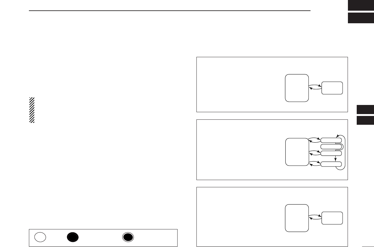
MEMORY CHANNEL WATCH
While operating on a VFO fre-
quency, priority watch checks for
a signal on the selected memory
channel every 5 sec.
•Amemory channel with skip infor-
mation can be watched.
MEMORY SCAN WATCH
While operating on a VFO fre-
quency, priority watch checks for
signals on each memory chan-
nel in sequence.
•The memory skip function and/or
memory bank scan is useful to
speed up the scan.
5 sec.
VFO
frequency Memory
channel
5 sec.
VFO
frequency
SKIP
Mch 000
Mch 001
Mch 001
Mch 999
VFO SCAN WATCH
While scanning in VFO mode,
priority watch checks for signals
on the selected memory chan-
nel every 5 sec.
5 sec.
VFO
scan Memory
channel
7
8
Push Push and hold Dual operation
43
8PRIORITY WATCH
DDMemory channel watch and memory scan watch
qSelect VFO mode, then set an operating frequency.
•TX channel can also be selected.
wPush [V/M] (
SKIP
•
S
.
MW
)to enter memory mode, then se-
lect the channel(s) to be watched.
For memory channel watch:
Rotate [DIAL] to select the desired memory channel.
For memory scan watch:
Push and hold [CALL] (
MODE
•
SCAN
)for 1 sec. to enter scan
type selection condition to select the scan type, then push
[CALL] (
MODE
•
SCAN
)again to start memory/bank scan.
eWhile pushing and holding [FUNC], push and hold
[SQL] (
ATT
•
SET
)for 1 sec. to enter set mode.
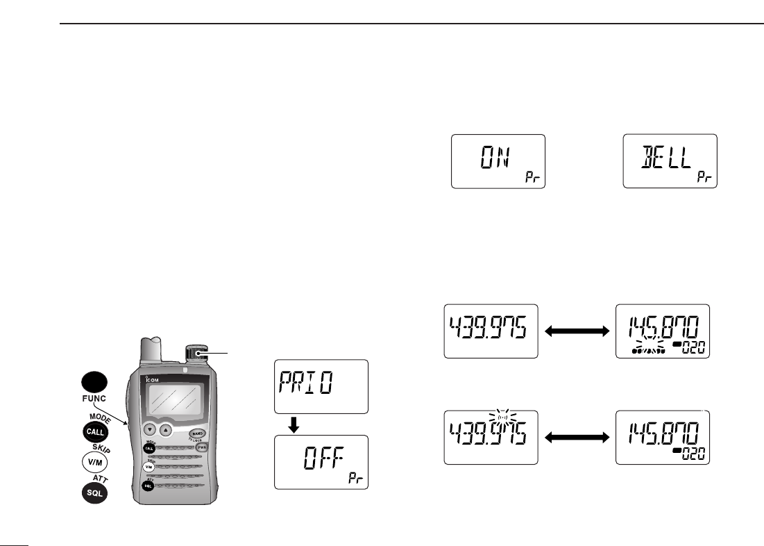
rRotate [DIAL] to select “PRIO.”
tWhile pushing and holding [FUNC], rotate [DIAL] to turn
the priority watch ON.
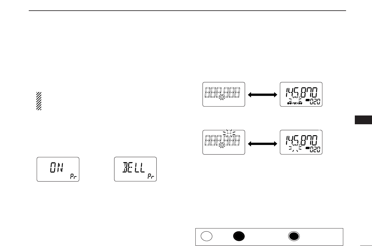
•Select “BELL” if the priority beep function is necessary.
yPush [SQL] (
ATT
•
SET
)to exit set mode and start the watch.
•“PRIO” indicator appears.
•The transceiver checks the memory/bank channel(s) every 5 sec.
•The watch resumes according to the selected scan resume con-
dition. (p. 41)
uWhile pushing and holding [FUNC], push [SQL] (
ATT
•
SET
)
to cancel the watch.
ATT
DTCS
TSQL
WFMAM -DUP
LOW
VOL PRIO PSKIP
MR
5
19
ATT
DTCS
TSQL
WFMAM -DUP
LOW
VOL PRIO PSKIP
MR
5
19
ATT
DTCS
TSQL
WFMAM -DUP
LOW
VOL PRIO PSKIP
MR
5
19
ATT
DTCS
TSQL
WFMAM -DUP
LOW
VOL PRIO PSKIP
MR
5
19
• During priority watch
Monitors VFO frequency
for 5 sec. Pauses on a memory (bank)
channel when a signal is received.
• During priority watch with priority beep
Emits beep and blinks “S” indicator when a signal is re-
ceived on a memory (bank) channel.
ATT
DTCS
TSQL
WFMAM -DUP
LOW
VOL PRIO P SK IP
MR
5
19
ATT
DTCS
TSQL
WFMAM -DUP
LOW
VOL PRIO P SK IP
MR
5
19
Priority ON Priority beep ON
SCAN
S.MW
SET
ATT
DTCS
TSQL
WFMAM -DUP
LOW
VOL PRIO P SK IP
MR
5
19
ATT
DTCS
TSQL
WFMAM -DUP
LOW
VOL PRIO P SK IP
MR
5
19
SET
[DIAL]
S.MW
SCAN
After 1 sec.
■Priority watch operation
44
8
PRIORITY WATCH
DDVFO scan watch
qPush [V/M] (
SKIP
•
S
.
MW
)to enter memory mode, then rotate
[DIAL] to select the memory channel.
wPush and hold [CALL] (
MODE
•
SCAN
)for 1 sec. to enter
scan type selection condition to select the scan type, then
push [CALL] (
MODE
•
SCAN
)again to start memory/bank
scan, if desired.
When scanning memory/bank channels:
Starts memory/bank scan first. Memory/bank scan can-
not be started after VFO scan is started.
eWhile pushing and holding [FUNC], push and hold
[SQL] (
ATT
•
SET
)for 1 sec. to enter set mode.
rRotate [DIAL] to select “PRIO.”
tWhile pushing and holding [FUNC], rotate [DIAL] to turn
the priority watch ON.
•Select “BELL” if the priority beep function is necessary.
yPush [SQL] (
ATT
•
SET
)to exit set mode and start the watch.
•“PRIO” indicator appears.
uPush [CALL] (
MODE
•
SCAN
)for 1 sec. to enter scan type se-
lection condition.
iRotate [DIAL] to select the desired scan type from “ALL,”
“BAND” and “PROGxx (xx= 0–24).”
oPush [CALL] (
MODE
•
SCAN
)to start the VFO scan watch.
•The transceiver checks the memory channel(s) every 5 sec.
•The watch resumes according to the selected scan resume con-
dition. (p. 41)
!0While pushing and holding [FUNC], push [SQL] (
ATT
•
SET
)
to cancel the watch and scan.
ATT
DTCS
TSQL
WFMAM -DUP
LOW
VOL PRIO PSKIP
MR
5
19
ATT
DTCS
TSQL
WFMAM -DUP
LOW
VOL PRIO PSKIP
MR
5
19
ATT
DTCS
TSQL
WFMAM -DUP
LOW
VOL PRIO PSKIP
MR
5
19
ATT
DTCS
TSQL
WFMAM -DUP
LOW
VOL PRIO PSKIP
MR
5
19
• During VFO scan watch
Searches VFO frequen-
cies for 5 sec. Pauses on a memory (bank)
channel when a signal is received.
• During VFO scan watch with priority beep
Emits beep and blinks “S” indicator when a signal is re-
ceived on a memory (bank) channel.
ATT
DTCS
TSQL
WFMAM -DUP
LOW
VOL PRIO P SK IP
MR
5
19
ATT
DTCS
TSQL
WFMAM -DUP
LOW
VOL PRIO P SK IP
MR
5
19
Priority ON Priority beep ON
8
Push Push and hold Dual operation
45
TONE SQUELCH AND POCKET BEEP
9
The tone or DTCS squelch opens only when receiving a sig-
nal with the same pre-programmed subaudible tone or DTCS
code, respectively. You can silently wait ffor a signal using the
same specified tone.
qSet the desired frequency in FM mode.
wWhile pushing and holding [FUNC], push and hold
[SQL] (
ATT
•
SET
)for 1 sec. to enter set mode.
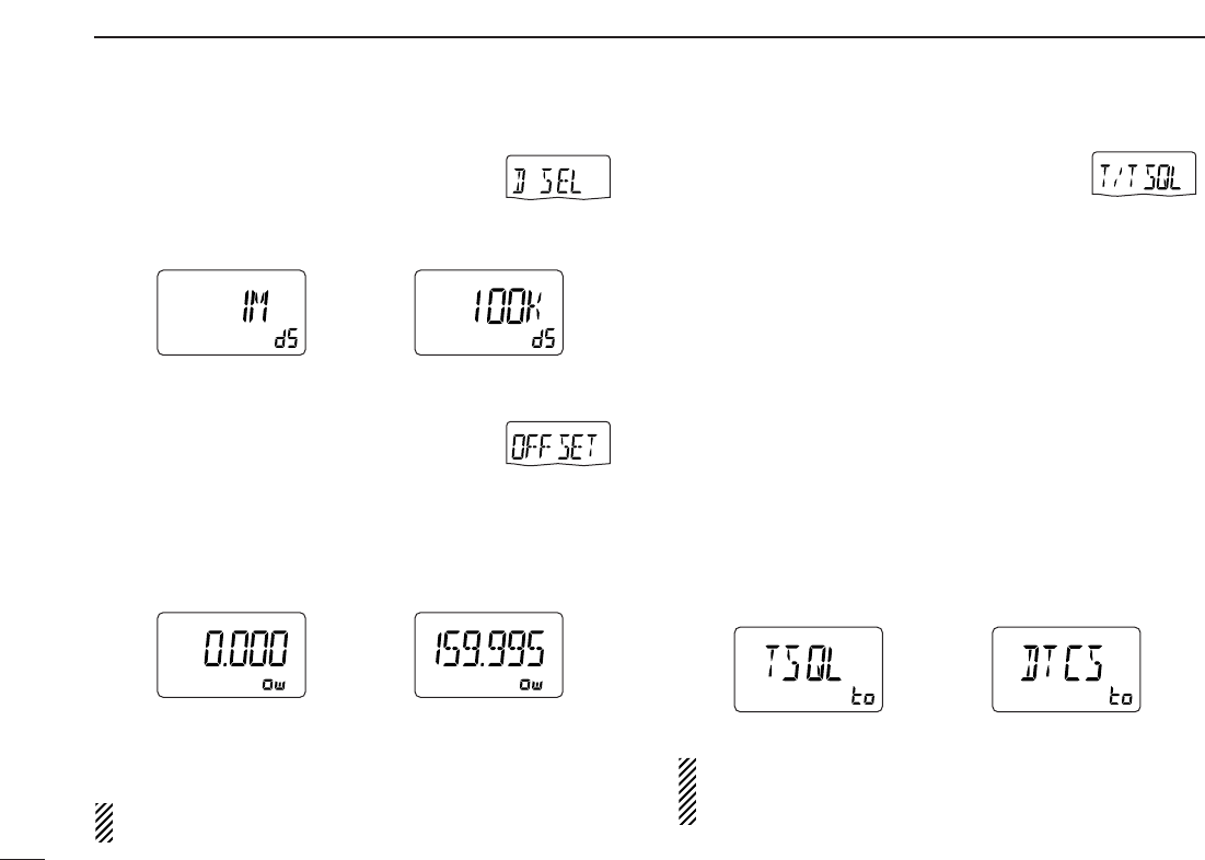
eRotate [DIAL] to select “T/TSQL.”
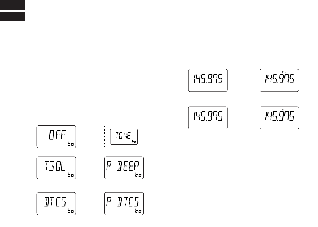
rWhile pushing and holding [FUNC], rotate [DIAL] to select
the desired tone squelch condition from “TSQL,” “P BEEP,”
“DTCS” and “P DTCS.”
tPush [SQL] (
ATT
•
SET
)to exit set mode.
•One of “TSQL,” TSQLS,” “DTCS” or “SDTCS” appears ac-
cording to the tone selection in the step r.
yWhen a signal with a matching tone is received, the
squelch opens and the transceiver emits audio.
When pocket beep function is activated, the transceiver
also emits beep tones and blinks “S.”
•Beep tones sound and “S” blinks for 30 sec.
uPush [FUNC] to manually stop the beeps and blinking.
•“S” disappears and the pocket beep function is deactivated.
iTo cancel the tone squelch or DTCS, select “OFF” with the
“T/TSQL” in the set mode, as described in step r.
ATT
DTCS
TSQL
WFMAM -DUP
LOW
VOL PRIO PSKIP
MR
5
19
ATT
DTCS
TSQL
WFMAM -DUP
LOW
VOL PRIO PSKIP
MR
5
19
ATT
DTCS
TSQL
WFMAM -DUP
LOW
VOL PRIO PSKIP
MR
5
19
ATT
DTCS
TSQL
WFMAM -DUP
LOW
VOL PRIO PSKIP
MR
5
19
Tone squelch selection
Tone squelch with pocket
beep function selection
DTCS selection DTCS with pocket beep
function selection
ATT
DTCS
TSQL
WFMAM -DUP
LOW
VOL PRIO P SK IP
MR
5
19
ATT
DTCS
TSQL
WFMAM -DUP
LOW
VOL PRIO P SK IP
MR
5
19
ATT
DTCS
TSQL
WFMAM -DUP
LOW
VOL PRIO P SK IP
MR
5
19
ATT
DTCS
TSQL
WFMAM -DUP
LOW
VOL PRIO P SK IP
MR
5
19
ATT
DTCS
TSQL
WFMAM -DUP
LOWVOL PRIO P SKIP
MR
5
19
ATT
DTCS
TSQL
WFMAM -DUP
LOW
VOL PRIO P SK IP
MR
5
19
Tone squelch selection
Tone squelch with pocket
beep function selection
DTCS selection DTCS with pocket beep
function selection
Subaudible tone OFF
Repeater tone selection
■Tone/DTCS squelch operation
46
9
TONE SQUELCH AND POCKET BEEP
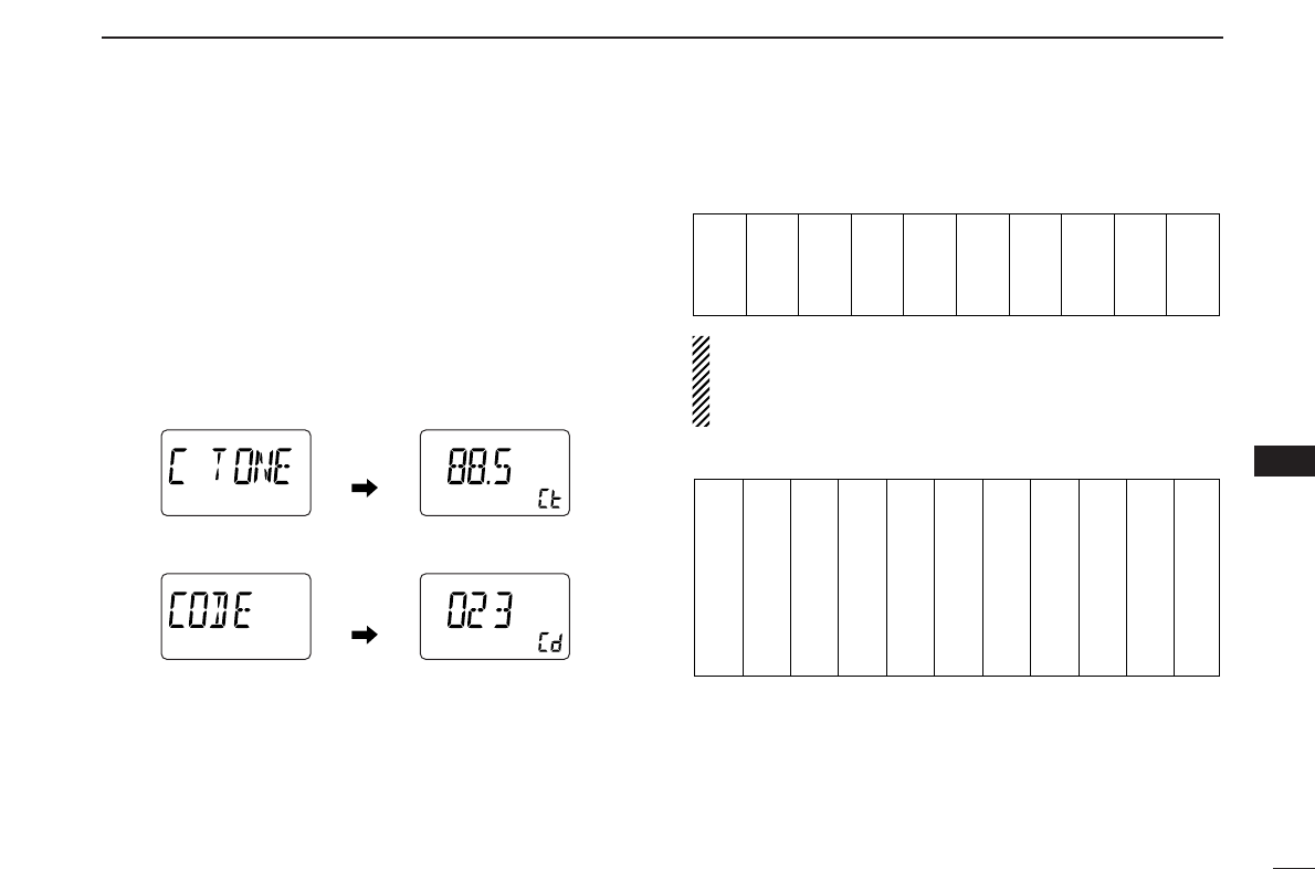
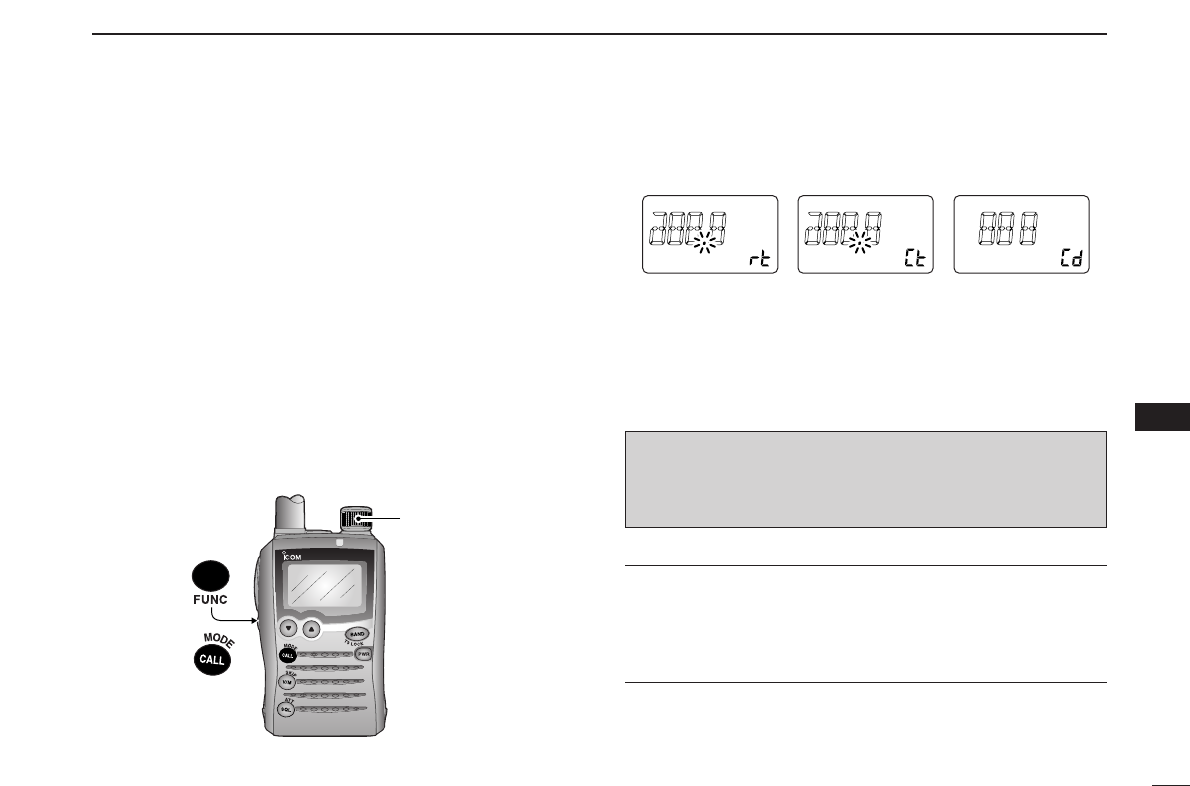
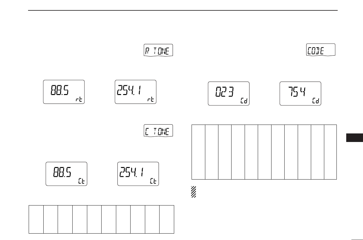
■Tone squelch frequency/DTCS code setting
88.5 Hz and 023 is set as the default for the tone squelch fre-
quency and the DTCS code, respectively. The frequency and
code can be selected as desired.
qWhile pushing and holding [FUNC], push and hold
[SQL] (
ATT
•
SET
)for 1 sec. to enter set mode.
wRotate [DIAL] to select “C TONE” when selecting the tone
squelch frequency; select “CODE” when selecting the
DTCS code.
eWhile pushing and holding [FUNC], rotate [DIAL] to select
the desired subaudible tone frequency or DTCS code.
•See the tables at right.
rPush [SQL] (
ATT
•
SET
)to exit set mode.
•Available tone frequency
NOTE: The transceiver has 50 tone frequencies and con-
sequently their spacing are narrow compared to units hav-
ing 38 tones. Therefore, some tone frequencies may
receive interference from adjacent tone frequencies.
•Available DTCS code
023
025
026
031
032
036
043
047
051
053
125
131
132
134
143
145
152
155
156
162
245
246
251
252
255
261
263
265
266
271
356
364
365
371
411
412
413
423
431
432
506
516
523
526
532
546
565
606
612
624
054
065
071
072
073
074
114
115
116
122
165
172
174
205
212
223
225
226
243
244
274
306
311
315
325
331
332
343
346
351
445
446
452
454
455
462
464
465
466
503
627
631
632
654
662
664
703
712
723
731
732
734
743
754
67.0
69.3
71.9
74.4
77.0
79.7
82.5
85.4
88.5
91.5
94.8
97.4
100.0
103.5
107.2
110.9
114.8
118.8
123.0
127.3
131.8
136.5
141.3
146.2
151.4
156.7
159.8
162.2
165.5
167.9
171.3
173.8
177.3
179.9
183.5
186.2
189.9
192.8
196.6
199.5
203.5
206.5
210.7
218.1
225.7
229.1
233.6
241.8
250.3
254.1
ATT
DTCS
TSQL
WFMAM -DUP
LOW
VOL PRIO P SK IP
MR
5
19
ATT
DTCS
TSQL
WFMAM -DUP
LOW
VOL PRIO P SKIP
MR
5
19
ATT
DTCS
TSQL
WFMAM -DUP
LOW
VOL PRIO P SK IP
MR
5
19
ATT
DTCS
TSQL
WFMAM -DUP
LOW
VOL PRIO P SK IP
MR
5
19
Tone squelch frequency selection
After
1 sec.
DTCS code selection
After
1 sec.
9
47
9TONE SQUELCH AND POCKET BEEP
As well as a code setting, the polarity setting is also available
for the DTCS operation. When a different polarity is set, the
DTCS never releases audio mute even when a signal with a
matching code number is received.
qWhile pushing and holding [FUNC], push and hold
[SQL] (
ATT
•
SET
)for 1 sec. to enter set mode.
wRotate [DIAL] to select “EXPAND.”
eWhile pushing and holding [FUNC], rotate [DIAL] to turn
the expanded set mode ON.
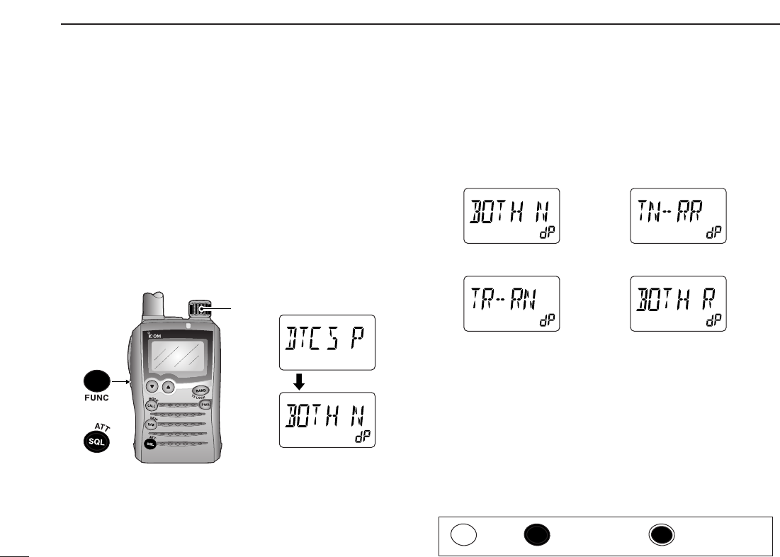
rRotate [DIAL] to select “DTCS P.”
tWhile pushing and holding [FUNC], rotate [DIAL] to select
the polarity from “BOTH N” (normal), “TN-RR” (TX: normal,
RX: reverse), “TR-RN” (TX: reverse, RX: normal) and
“BOTH R” (reverse).
yPush [SQL] (
ATT
•
SET
)to exit set mode.
ATT
DTCS
TSQL
WFMAM -DUP
LOW
VOL PRIO P SK IP
MR
5
19
ATT
DTCS
TSQL
WFMAM -DUP
LOW
VOL PRIO P SK IP
MR
5
19
ATT
DTCS
TSQL
WFMAM -DUP
LOW
VOL PRIO P SK IP
MR
5
19
ATT
DTCS
TSQL
WFMAM -DUP
LOW
VOL PRIO P SK IP
MR
5
19
TX/RX: Normal polarity TX: Normal, RX: Reverse
TX: Reverse, RX: Normal TX/RX: Reverse polarity
SCAN
S.MW
SET
ATT
DTCS
TSQL
WFMAM -DUP
LOW
VOL PRIO P SK IP
MR
5
19
ATT
DTCS
TSQL
WFMAM -DUP
LOW
VOL PRIO P SK IP
MR
5
19
After 1 sec.
SET
[DIAL]
■DTCS polarity setting
Push Push and hold Dual operation
48
9
TONE SQUELCH AND POCKET BEEP
By monitoring a signal that is being operated with pocket
beep, tone or DTCS squelch function, you can determine the
tone frequency or DTCS code necessary to open a squelch.
qSet the frequency to be checked for a tone frequency or
code.
wTurn the desired tone type ON in set mode; “TONE” (re-
peater tone), “TSQL” (tone squelch) or “DTCS” (DTCS
squelch).
•One of “T,” “TSQL” or “DTCS” appears.
•Even if the pocket beep function is activated, it is cancelled when
the tone scan is started.
eWhile pushing and holding [FUNC], push [CALL]
(
MODE
•
SCAN
)for 1 sec. to start the tone scan.
•To change the scanning direction, rotate [DIAL].
rWhen the CTCSS tone frequency or 3-digit DTCS code is
matched, the squelch opens and the tone frequency or
code is temporarily programmed into the selected condi-
tion, such as a memory channel.
•The tone scan pauses when a CTCSS tone frequency or 3-digit
DTCS code is detected.
✔
CONVENIENT!
Even if no tone type is selected, pushing and holding [CALL]
(
MODE
•
SCAN
)for 1 sec. while pushing and holding [FUNC]
also starts tone scan. In this case, the tone scan searches for
repeater tone frequency only.
☞NOTE: The decoded tone frequency or code is pro-
grammed temporarily when a memory channel is se-
lected. However, this will be cleared when the memory
channel is re-selected.
ATT
DTCS
TSQL
WFMAM -DUP
LOW
VOL PRIO P SK IP
MR
5
19
ATT
DTCS
TSQL
WFMAM -DUP
LOW
VOL PRIO P SK IP
MR
5
19
ATT
DTCS
TSQL
WFMAM -DUP
LOW
VOL PRIO P SK IP
MR
5
19
DTCS scanTone squelch scanRepeater tone scan
SCAN
S.MW
SET
[DIAL]
SCAN
■Tone scan
9
49
SET MODE
10
■General
Set mode is used for programming infrequently changed val-
ues or conditions of functions.
In addition, the IC-P7A has an expanded set mode which is
used for programming even more infrequently changed val-
ues or conditions of functions. When turning the expanded
set mode OFF, only half of the set mode items are displayed
for simple operation.
DDSet mode entering and operation
qWhile pushing and holding [FUNC], push and hold
[SQL] (
ATT
•
SET
)for 1 sec. to enter set mode.
wRotate [DIAL] to select the desired item.
eWhile pushing and holding [FUNC], rotate [DIAL] to select
the desired value or condition.
rPush [SQL] (
ATT
•
SET
)to exit set mode, or rotate [DIAL] to
select another set mode item.
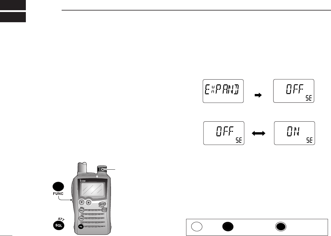
DDExpanded set mode ON/OFF
qWhile pushing and holding [FUNC], push and hold
[SQL] (
ATT
•
SET
)for 1 sec. to enter set mode.
wRotate [DIAL] to select “EXPAND.”
eWhile pushing and holding [FUNC], rotate [DIAL] to turn
the expanded set mode ON and OFF.
rRotate [DIAL] to select the desired item.
tWhile pushing and holding [FUNC], rotate [DIAL] to select
the desired value or condition.
yPush [SQL] (
ATT
•
SET
)to exit set mode, or rotate [DIAL] to
select another item.
ATT
DTCS
TSQL
WFMAM -DUP
LOW
VOL PRIO P SK IP
MR
5
19
ATT
DTCS
TSQL
WFMAM -DUP
LOW
VOL PRIO P SK IP
MR
5
19
Expanded set mode OFF Expanded set mode ON
ATT
DTCS
TSQL
WFMAM -DUP
LOW
VOL PRIO P SK IP
MR
5
19
ATT
DTCS
TSQL
WFMAM -DUP
LOW
VOL PRIO P SK IP
MR
5
19
After
1 sec.
SCAN
S.MW
SET
SET
[DIAL]
Push Push and hold Dual operation
50
10
SET MODE
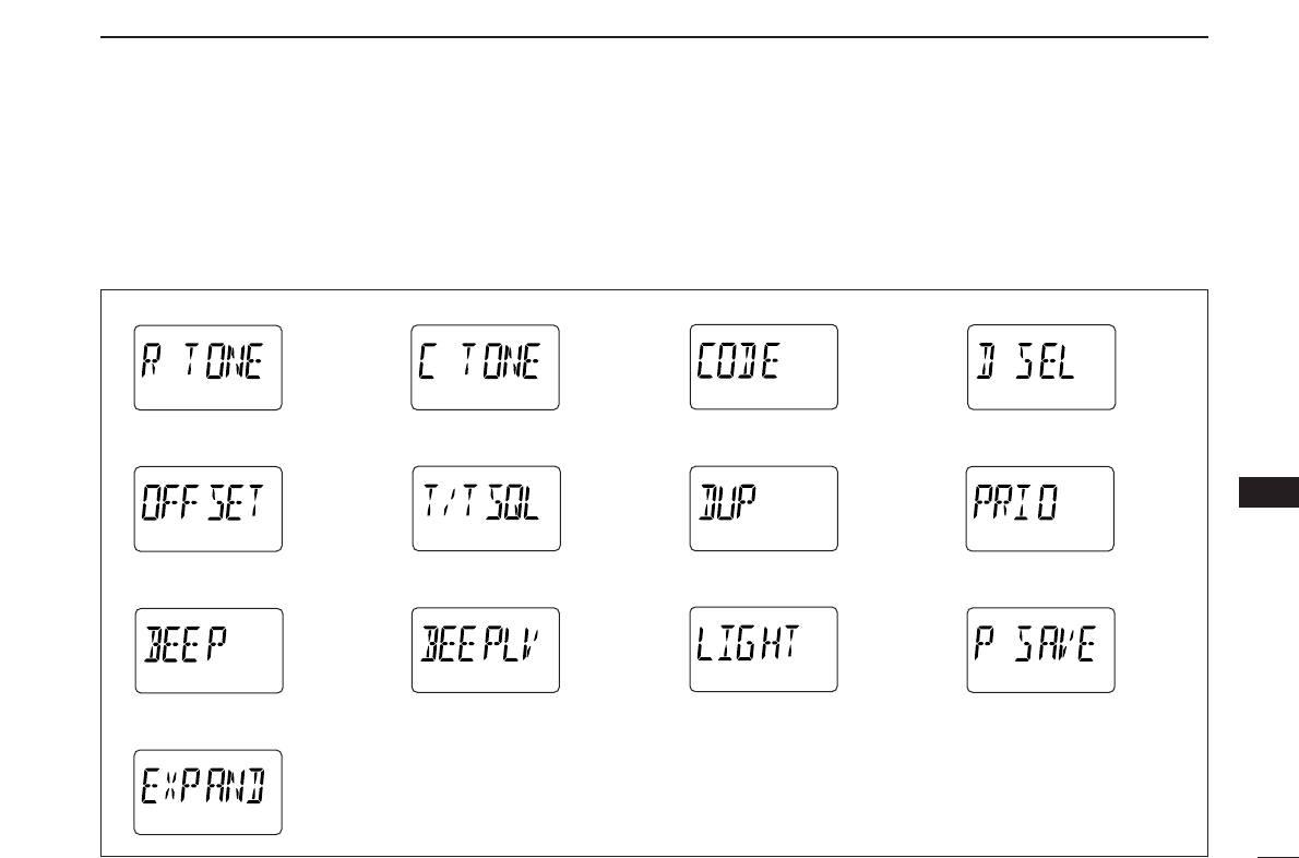
■Set mode items
The following items are available in the set mode and ex-
panded set mode.
DDGeneral set mode items
10
• Repeater tone (p. 52) • Tone squelch tone (p. 52)
• Key-touch beep (p. 54) • Beep output level (p. 54) • Display backlighting (p. 55)
• DTCS code (p. 52)
• Tone selection (p. 53) • Duplex direction (p. 54)
• Offset frequency (p. 53)
• Dial select step (p. 53)
• Priority watch (p. 54)
• Expanded set mode (p. 49)
• Power save (p. 55)
51
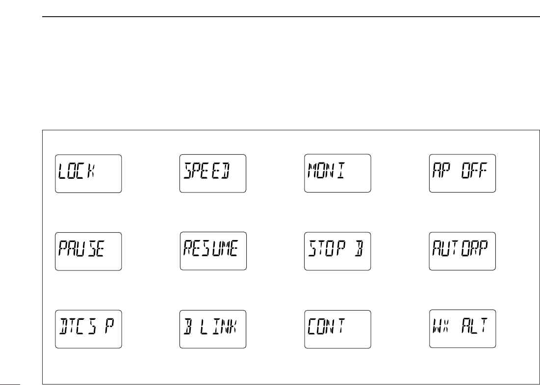
10 SET MODE
DDExpanded set mode items *Available for the USA and Korea versions only.
†Available for the USA version only.
• Key lock effect (p. 46) • Dial speed acceleration (p. 56)
• Auto repeater* (p. 58)
• DTCS polarity (p. 58) • Bank link (p. 59)
• Monitor key action (p. 56)
• Scan resume timer (p. 57)
• Scan pause timer (p. 57)
• Auto power OFF (p. 57)
• Scan stop beep (p. 57)
• Weather alert† (p. 59)
• LCD contrast (p. 59)
52
10
SET MODE
DDRepeater tone frequency
Selects subaudible tone frequency for ac-
cessing a repeater, etc. Total of 50 tone fre-
quencies (67.0–254.1 Hz) are available.
(default: 88.5 Hz)
DDTone squelch frequency
Selects tone frequency for tone squelch or
pocket beep operation from one of 50 avail-
able frequencies (67.0–254.1 Hz).
(default: 88.5 Hz)
•Available subaudible tone frequencies
DDDTCS code
Selects DTCS (both encoder/decoder) code
for DTCS squelch operation. Total of 104
codes (023–754) are available.
(default: 023)
•Available DTCS code
The polarity can also be set in “DTCS P” as described on
page 58.
023
025
026
031
032
036
043
047
051
053
125
131
132
134
143
145
152
155
156
162
245
246
251
252
255
261
263
265
266
271
356
364
365
371
411
412
413
423
431
432
506
516
523
526
532
546
565
606
612
624
054
065
071
072
073
074
114
115
116
122
165
172
174
205
212
223
225
226
243
244
274
306
311
315
325
331
332
343
346
351
445
446
452
454
455
462
464
465
466
503
627
631
632
654
662
664
703
712
723
731
732
734
743
754
ATT
DTCS
TSQL
WFMAM -DUP
LOW
VOL PRIO P SK IP
MR
5
19
ATT
DTCS
TSQL
WFMAM -DUP
LOW
VOL PRIO P SK IP
MR
5
19
Code 023 setting Code 754 setting
67.0
69.3
71.9
74.4
77.0
79.7
82.5
85.4
88.5
91.5
94.8
97.4
100.0
103.5
107.2
110.9
114.8
118.8
123.0
127.3
131.8
136.5
141.3
146.2
151.4
156.7
159.8
162.2
165.5
167.9
171.3
173.8
177.3
179.9
183.5
186.2
189.9
192.8
196.6
199.5
203.5
206.5
210.7
218.1
225.7
229.1
233.6
241.8
250.3
254.1
ATT
DTCS
TSQL
WFMAM -DUP
LOW
VOL PRIO P SKIP
MR
5
19
ATT
DTCS
TSQL
WFMAM -DUP
LOW
VOL PRIO P SK IP
MR
5
19
88.5 Hz setting 254.1 Hz setting
ATT
DTCS
TSQL
WFMAM -DUP
LOW
VOL PRIO P SK IP
MR
5
19
ATT
DTCS
TSQL
WFMAM -DUP
LOW
VOL PRIO P SK IP
MR
5
19
88.5 Hz setting 254.1 Hz setting
10
53
10 SET MODE
DDDial select step
Select the tuning step while pushing and
holding [FUNC] from 100 kHz, 1 MHz (de-
fault) and 10 MHz.
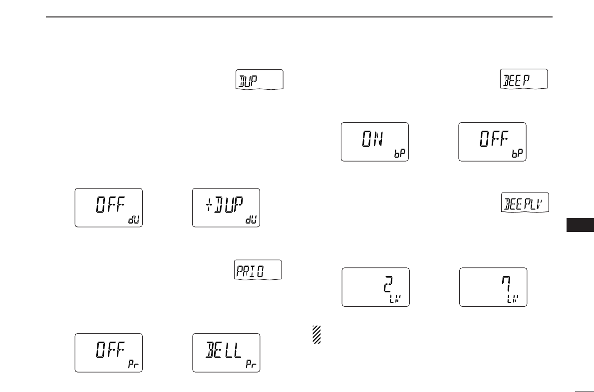
DDOffset frequency
Sets the offset frequency for duplex (re-
peater) operation for each frequency band in-
dependently within 0 to 159.995 MHz range.
During duplex operation (–DUP or +DUP),
the offset frequency shifts the transmit fre-
quency (or while [SQL] (
ATT
•
SET
)is pushed).
The default value may differ according to the selected fre-
quency band (before accessing set mode)and transceiver ver-
sion.
The selected tuning step in VFO mode is used for setting
the offset frequency.
DDTone selection
Sets the tone encoder, tone squelch or DTCS
squelch operation and pocket beep capabil-
ity, when waiting for the desired signal.
•OFF : Regular noise squelch operation. (default)
•TONE : Using tone encoder. Some repeaters require
subaudible tones to be accessed.
•TSQL : Using tone squelch. The squelch opens only
when a signal with matched subaudible tone is
received.
•PBEEP : In addition to the “TSQL” setting, alert beeps
will sound when a signal with matched tone is
received.
•DTCS : Using DTCS squelch. The squelch opens only
when a signal with matched DTCS code is re-
ceived.
•PDTCS : In addition to the “DTCS” setting, alert beeps
will sound when a signal with matched DTCS
code is received.
The subaudible tone frequency and DTCS code are pro-
grammed as the tone frequency and DTCS code items, re-
spectively.
ATT
DTCS
TSQL
WFMAM -DUP
LOW
VOL PRIO P SK IP
MR
5
19
ATT
DTCS
TSQL
WFMAM -DUP
LOW
VOL PRIO P SK IP
MR
5
19
DTCS squelch operationTone squelch operation
ATT
DTCS
TSQL
WFMAM -DUP
LOW
VOL PRIO P SK IP
MR
5
19
ATT
DTCS
TSQL
WFMAM -DUP
LOW
VOL PRIO P SK IP
MR
5
19
ATT
DTCS
TSQL
WFMAM -DUP
LOW
VOL PRIO P SK IP
MR
5
19
ATT
DTCS
TSQL
WFMAM -DUP
LOW
VOL PRIO P SK IP
MR
5
19
1 MHz step 100 kHz step
54
10
SET MODE
DDDuplex direction
Sets the duplex direction. The transmit fre-
quency is shifted from the receive frequency by
the offset frequency when transmitting or when
the monitor function is in use.
•OFF : Simplex operation. (default)
•–DUP : The transmit frequency shifts down while trans-
mitting.
•+DUP : The transmit frequency shifts up while transmit-
ting.
DDPriority watch
Turn the priority watch or priority beep (prior-
ity watch with beep capability) ON. (default: OFF)
•ON: Start priority watch after exiting set mode.
•BELL : Emits beeps and blinking “S” indicator when a
signal is received on the priority frequency.
DDKey-touch beep
The key-touch beep can be turned OFF for
silent operation.
(default: ON)
DDBeep output level
Adjust the key-touch beep tone level to the
desired level within 8 levels.
Beep tone sounds while setting. The tone sound let you know
the approximate sound level.
(default: 2)
The key-touch beep (previous item) must be set to ON to
have a beep tone.
ATT
DTCS
TSQL
WFMAM -DUP
LOW
VOL PRIO P SK IP
MR
5
19
ATT
DTCS
TSQL
WFMAM -DUP
LOW
VOL PRIO P SK IP
MR
5
19
Default level Maximum level
ATT
DTCS
TSQL
WFMAM -DUP
LOW
VOL PRIO P SK IP
MR
5
19
ATT
DTCS
TSQL
WFMAM -DUP
LOW
VOL PRIO P SK IP
MR
5
19
Key-touch beep ON Key-touch beep OFF
ATT
DTCS
TSQL
WFMAM -DUP
LOW
VOL PRIO P SK IP
MR
5
19
ATT
DTCS
TSQL
WFMAM -DUP
LOW
VOL PRIO P SK IP
MR
5
19
Priority watch OFF Priority beep ON
ATT
DTCS
TSQL
WFMAM -DUP
LOW
VOL PRIO P SK IP
MR
5
19
ATT
DTCS
TSQL
WFMAM -DUP
LOW
VOL PRIO P SK IP
MR
5
19
Simplex operation Positive duplex operation
10
55
10 SET MODE
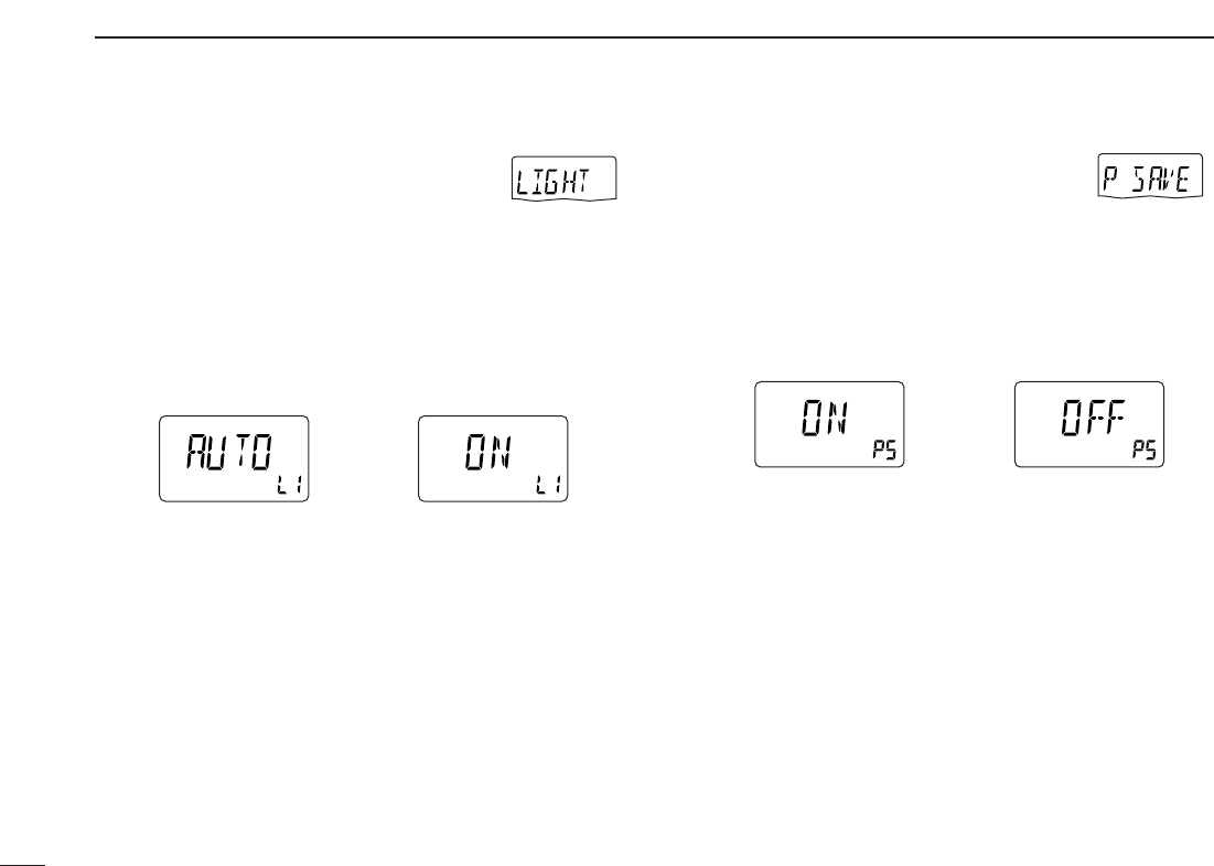
DDDisplay backlighting
The transceiver has display backlighting with
a 5 sec. timer for night time operation. The
backlighting can be turned ON continuously
or turned OFF, if desired.
•AUTO: Lights when an operation is performed, goes out
after 5 sec. (default)
•ON: Lights continuously during transceiver power is
ON.
•OFF : Never lights.
DDPower save
The power save function reduces the current
drain to conserve battery power. This power
save function can be turned OFF, if desired.
In the default setting (“ON” selection), the power save func-
tion is activated in 1:4 (125 msec.: 500 msec.) ratio when no sig-
nal is received for 5 sec. The ratio becomes 1:8 (125 msec.:
1sec.) when no signal is received for another 60 sec.
ATT
DTCS
TSQL
WFMAM -DUP
LOW
VOL PRIO P SK IP
MR
5
19
ATT
DTCS
TSQL
WFMAM -DUP
LOW
VOL PRIO P SK IP
MR
5
19
Power save ON Power save OFF
ATT
DTCS
TSQL
WFMAM -DUP
LOW
VOL PRIO P SK IP
MR
5
19
ATT
DTCS
TSQL
WFMAM -DUP
LOW
VOL PRIO P SK IP
MR
5
19
Auto setting Continuously ON setting
56
10
SET MODE
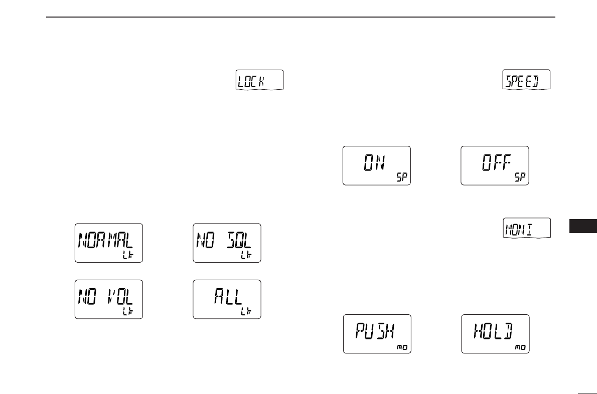
DDKey lock effect
While the key lock function is ON, [YY]/[ZZ]and
[SQL] (
ATT
•
SET
)can still be accessed. Accessible keys can
be set to one of 4 groups.
[PWR] and [FUNC]+[BAND] (
TS
•
LOCK
)are also accessible
during the lock, however, these keys are not effected by this
setting.
•NORMAL : [YY]/[ZZ]and [SQL] (
ATT
•
SET
)are accessible.
(default)
•NO SQL : [SQL] (
ATT
•
SET
)is accessible.
•NO VOL : [YY]/[ZZ]are accessible.
•ALL : No accessible key is available, except [PWR]
and [FUNC]+[BAND] (
TS
•
LOCK
).
DDDial speed acceleration
The dial speed acceleration automatically
speeds up the tuning dial speed when rotating [DIAL] rapidly.
•ON: The dial speed acceleration is tuned ON.
(default)
•OFF : The dial speed acceleration is turned OFF.
DDMonitor key action
The monitor key, [SQL] (
ATT
•
SET
), can be set
as a ‘sticky’ key. When set to the sticky condition, each push
of [SQL] (
ATT
•
SET
)toggles the monitor function ON and OFF.
•PUSH: Pushing and holding [SQL] (
ATT
•
SET
)to monitor
the frequency. (default)
•HOLD : Push [SQL] (
ATT
•
SET
)momentarily to monitor the
frequency and push momentarily again to cancel it.
ATT
DTCS
TSQL
WFMAM -DUP
LOW
VOL PRIO P SK IP
MR
5
19
ATT
DTCS
TSQL
WFMAM -DUP
LOW
VOL PRIO P SK IP
MR
5
19
Monitor key activates
as HOLD function key.
Monitor key activates
as PUSH function key.
Push and hold [SQL] to monitor Push to monitor
ATT
DTCS
TSQL
WFMAM -DUP
LOW
VOL PRIO P SK IP
MR
5
19
ATT
DTCS
TSQL
WFMAM -DUP
LOW
VOL PRIO P SK IP
MR
5
19
The acceleration ON The acceleration OFF
ATT
DTCS
TSQL
WFMAM -DUP
LOW
VOL PRIO P SK IP
MR
5
19
ATT
DTCS
TSQL
WFMAM -DUP
LOW
VOL PRIO P SK IP
MR
5
19
ATT
DTCS
TSQL
WFMAM -DUP
LOW
VOL PRIO P SK IP
MR
5
19
ATT
DTCS
TSQL
WFMAM -DUP
LOW
VOL PRIO P SK IP
MR
5
19
Normal lock condition Squelch level can be adjusted
Audio output can be adjusted Transceiver power and lock
function only switchable
10
57
10 SET MODE
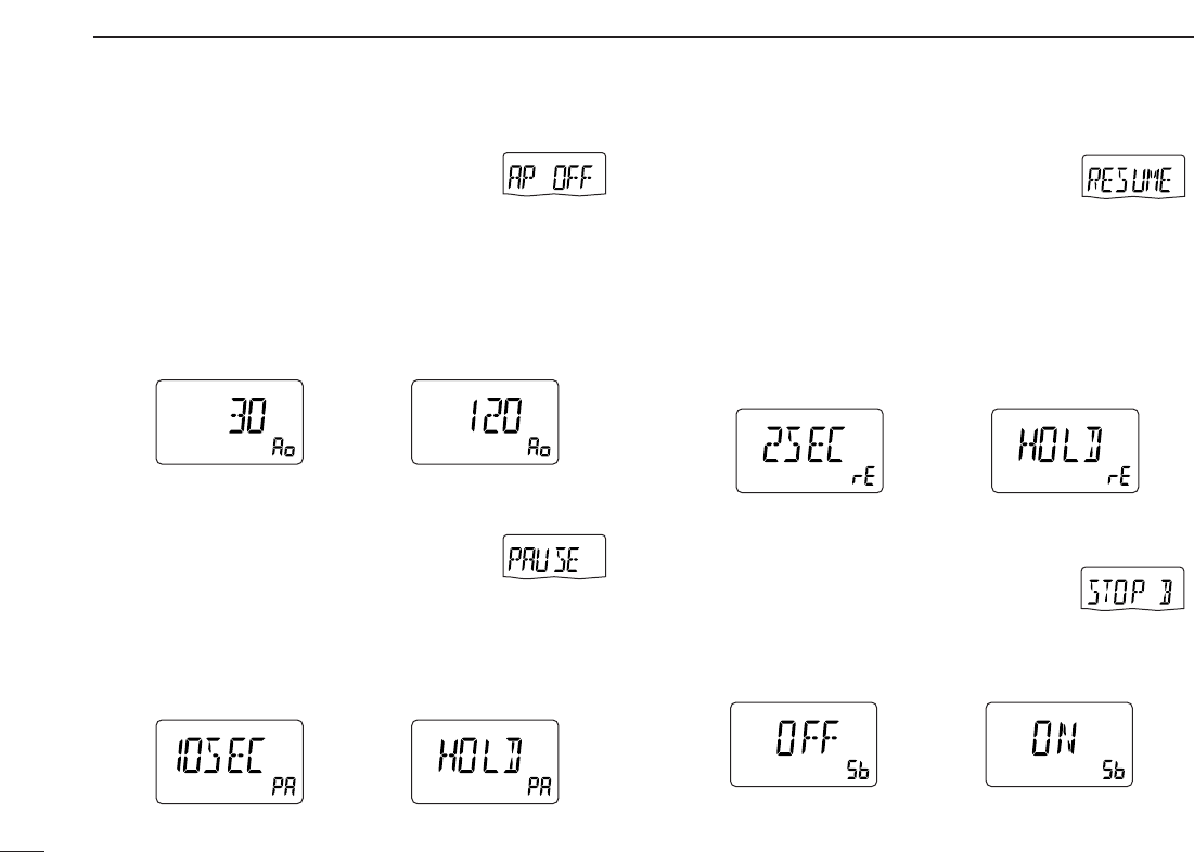
DDAuto power OFF
The transceiver can be set to automatically
turn OFF after a specified period with a beep when no key
operations are performed.
30 min., 1 hour, 1.5 hours, 2 hours and OFF (default) can be
specified. The specified period is retained even when the
transceiver is turned OFF by the auto power OFF function. To
cancel the function, select “OFF” in this set mode.
DDScan pause timer
Selects the scan pause time. When receiving
signals, the scan pauses according to the scan pause time.
•2–20 : Scan pauses for 2–20 sec. on a received signal,
and is selected in 2 sec. steps. (default: 10 sec.)
•HOLD: Scan pauses on a received signal until it disap-
pears. Rotate [DIAL] to resume manually.
DDScan resume timer
Selects scan resume time. Scan resumes
after the specified period when the received signal disap-
pears.
•0 : Scan resumes immediately when the received
signal disappears.
•1–5 : Scan pause 1–5 sec. after the received signal
disappears. (default: 2 sec.)
•HOLD: Scan pauses on the received signal even if it dis-
appears. Rotate [DIAL] to resume manually.
DDScan stop beep
Turns the scan stop beep function ON and
OFF (default).
When the function is activated (“ON” is selected), a long beep
will sound each time a signal is received during scan.
ATT
DTCS
TSQL
WFMAM -DUP
LOW
VOL PRIO P SK IP
MR
5
19
ATT
DTCS
TSQL
WFMAM -DUP
LOW
VOL PRIO P SK IP
MR
5
19
No beep is sound when
receiving a signal A long beep is sound when
receiving a signal
ATT
DTCS
TSQL
WFMAM -DUP
LOW
VOL PRIO P SK IP
MR
5
19
ATT
DTCS
TSQL
WFMAM -DUP
LOW
VOL PRIO P SK IP
MR
5
19
Scan resumes after 2 sec. Scan resumes manually
ATT
DTCS
TSQL
WFMAM -DUP
LOW
VOL PRIO P SK IP
MR
5
19
ATT
DTCS
TSQL
WFMAM -DUP
LOW
VOL PRIO P SKIP
MR
5
19
Scan pauses for 10 sec. Scan pauses until signal
disappears
ATT
DTCS
TSQL
WFMAM -DUP
LOW
VOL PRIO P SK IP
MR
5
19
ATT
DTCS
TSQL
WFMAM -DUP
LOW
VOL PRIO P SK IP
MR
5
19
30 min. timer 2 hrs. timer
58
10
SET MODE
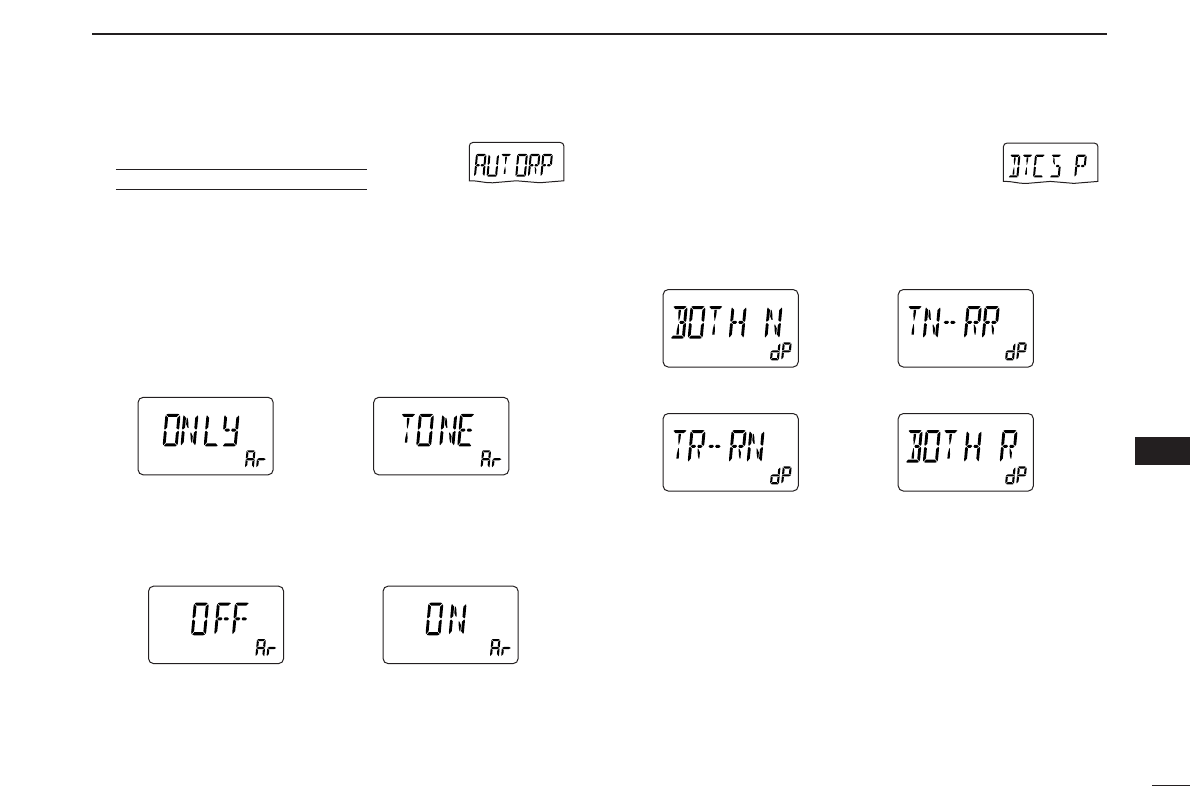
DDAuto repeater
The auto repeater function automatically turns ON or OFF the
duplex operation and tone encoder. The offset and repeater
tone is not changed by the auto repeater function. Reset
these frequencies, if necessary.
U.S.A. version:
•OFF : The auto repeater function is turned OFF.
•DUP ONLY : Activates for duplex only. (default)
•DUP TONE : Activates for duplex and tone.
Korea version:
•OFF : Deactivates the function.
•ON: Activates duplex and tone. (default)
DDDTCS polarity
Sets DTCS polarity from “BOTH N” (TX/RX:
normal), “TN-RR” (TX: normal, RX: reverse),
“TR-RN” (TX: reverse, RX: normal) and
“BOTH R” (TX/RX: reverse).
(default: BOTH N)
ATT
DTCS
TSQL
WFMAM -DUP
LOW
VOL PRIO P SK IP
MR
5
19
ATT
DTCS
TSQL
WFMAM -DUP
LOW
VOL PRIO P SK IP
MR
5
19
ATT
DTCS
TSQL
WFMAM -DUP
LOW
VOL PRIO P SK IP
MR
5
19
ATT
DTCS
TSQL
WFMAM -DUP
LOW
VOL PRIO P SK IP
MR
5
19
TX/RX: Normal polarity TX: Normal, RX: Reverse
TX: Reverse, RX: Normal TX/RX: Reverse polarity
ATT
DTCS
TSQL
WFMAM -DUP
LOW
VOL PRIO P SK IP
MR
5
19
ATT
DTCS
TSQL
WFMAM -DUP
LOW
VOL PRIO P SK IP
MR
5
19
Auto repeater OFF Auto repeater ON
ATT
DTCS
TSQL
WFMAM -DUP
LOW
VOL PRIO P SK IP
MR
5
19
ATT
DTCS
TSQL
WFMAM -DUP
LOW
VOL PRIO P SK IP
MR
5
19
Duplex only Duplex and tone
U.S.A./KOREA versions only
10
59
10 SET MODE
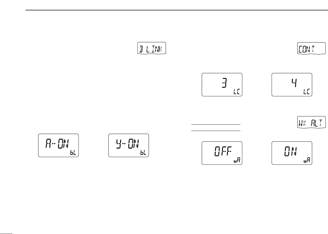
DDMemory bank link function
Sets the memory bank link function ON (de-
fault) and OFF. The link function provides
continuous bank scan, scanning all contents
in the selected banks during bank scan.
•Bank link setting
qWhile pushing and holding [FUNC], rotate [DIAL] to select
the desired bank to be linked.
•“A-ON” to “y-ON” appears.
• A to H, J, L, N, O to R, T, U and y are available for usage by
group
wPush [CALL] (
MODE
•
SCAN
)to select “ON” to link the bank.
eRepeat steps qand wto link other banks.
•To cancel the memory bank link function, repeat steps qand
wto select “OFF.”
DDLCD contrast
Sets the LCD contrast within 1 to 4 levels as
desired.
(default: 3)
DDWeather alert function
Turns weather alert function ON and OFF.
ATT
DTCS
TSQL
WFMAM -DUP
LOW
VOL PRIO P SK IP
MR
5
19
ATT
DTCS
TSQL
WFMAM -DUP
LOW
VOL PRIO P SK IP
MR
5
19
Weather alert OFF Weather alert ON
U.S.A. version only
ATT
DTCS
TSQL
WFMAM -DUP
LOW
VOL PRIO P SK IP
MR
5
19
ATT
DTCS
TSQL
WFMAM -DUP
LOW
VOL PRIO P SK IP
MR
5
19
Contrast 3 setting Contrast 4 setting
ATT
DTCS
TSQL
WFMAM -DUP
LOW
VOL PRIO P SK IP
MR
5
19
ATT
DTCS
TSQL
WFMAM -DUP
LOW
VOL PRIO P SK IP
MR
5
19
Bank A is linked Bank Y is linked
60
11
OTHER FUNCTIONS
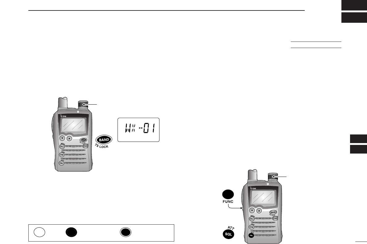
DDWeather channel selection
qSelect VFO mode with [V/M] (
SKIP
•
S
.
MW
).
wPush [BAND] (
TS
•
LOCK
)several times, or while pushing
and holding [BAND] (
TS
•
LOCK
)rotate [DIAL] to select the
weather channel group.
eRotate [DIAL] to select the desired weather channel.
rPush [BAND] (
TS
•
LOCK
)to change frequency band, or
push [V/M] (
SKIP
•
S
.
MW
)to select memory mode.
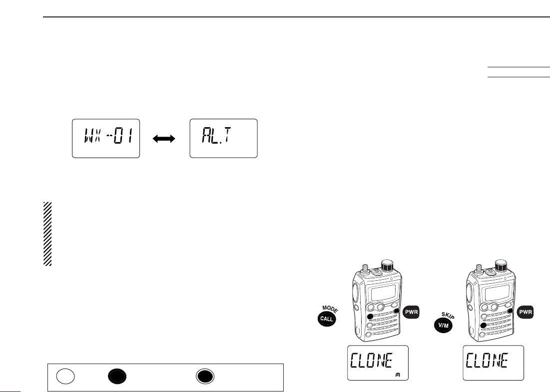
DDWeather alert function
NOAA broadcast stations transmit weather alert tones before
important weather announcements. When the weather alert
function is turned ON, the selected weather channel is moni-
tored once every 5 sec. for the announcement. When the alert
signal is detected, the “AL.T” and the WX channel are dis-
played alternately and sounds a beep tone until the transceiver
is operated. The previously selected (used) weather channel
is checked periodically during standby or while scanning.
qSelect the desired weather channel.
wTurn the weather alert function ON in expanded set mode.
➥While pushing and holding [FUNC], push and hold
[SQL] (
ATT
•
SET
)to enter set mode.
➥Rotate [DIAL] to select “WX ALT,” then rotate [DIAL]
while pushing and holding [FUNC] to set ON.
➥Push [SQL] (
ATT
•
SET
)to exit set mode.
SCAN
S.MW
SET
SET
[DIAL]
SCAN
S.MW
SET
ATT
DTCS
TSQL
WFMAM -DUP
LOW
VOL PRIO P SK IP
MR
5
19
Weather channel indication
[DIAL]
10
11
■Weather channel operation U.S.A. version only
Push Push and hold Dual operation
61
11 OTHER FUNCTIONS
eSet the desired stand-by condition.
•Select VFO or memory channel.
•Scan or priority watch operation can also be selected.
rWhen the alert is detected, a beep sounds and the follow-
ing indication will be displayed.
tTurn the weather alert function OFF in set mode.
NOTE: While receiving a signal (on a frequency other than
the weather alert ON frequency), the receiving signal or
audio will be interrupted momentarily every 5 sec. (approx.)
in case the alert function is turned ON. This symptom is
caused by the WX alert function. To cancel these symp-
toms, set the weather alert item OFF in set mode.
■Data cloning
Cloning allows you to quickly and easily transfer the pro-
grammed contents from one transceiver to another; or data
from a personal computer to a transceiver using the optional
CS-P7
CLONING SOFTWARE
.
DCloning between transceivers
qMaster transceiver:
While pushing and holding [CALL] (
MODE
•
SCAN
), turn
power ON to enter cloning mode.
•The master transceiver is used to send data to the sub-trans-
ceiver.
Sub-transceiver:
While pushing and holding [V/M] (
SKIP
•
S
.
MW
), turn power
ON to enter cloning mode.
ATT
DTCS
TSQL
WFMAM -DUP
LOW
VOL PRIO P SKIP
MR
5
19
ATT
DTCS
T SQL
WFMAM -DUP
LOW
VOL PRIO P SKIP
MR
5
19
Master
transceiver
Sub-
transceiver
SCAN
S.MW
“CLONE” and “m” appear “CLONE” appears
AT
POWER ON
ATT
DTCS
TSQL
WFMAM -DUP
LOW
VOL PRIO P SK IP
MR
5
19
ATT
DTCS
TSQL
WFMAM -DUP
LOW
VOL PRIO P SKIP
MR
5
19
Show above indications alternately.
Push Push and hold Dual operation
62
11
OTHER FUNCTIONS
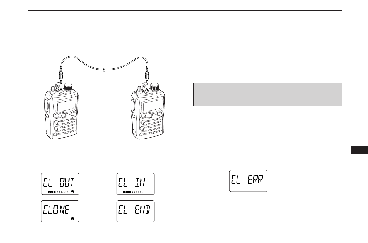
wConnect the OPC-474 cloning cable to the [MIC/SP] jack
of the master and sub-transceivers.
ePush [SQL] (
ATT
•
SET
)on the master transceiver.
•The transceiver show following indications.
rWhen cloning is finished, turn power OFF, then ON to exit
cloning mode.
DCloning using a personal computer
Data can be cloned to and from a personal computer (Mi-
crosoft®Windows®98/98SE/Me/2000/XP) using the optional
CS-P7
CLONING SOFTWARE
and the optional OPC-478/478U
CLONING CABLE
. Consult the CS-P7
CLONING SOFTWARE
HELP
file for details.
DCloning error
☞NOTE: DO NOT push any key on the sub-transceiver dur-
ing cloning. This will cause a cloning error.
When the display appears as below, a cloning error has oc-
curred.
In such a case, both transceivers automatically return to the
clone standby condition and cloning must be repeated.
Microsoft and Windows are registered trademarks of Microsoft Corporation in
the U.S.A. and other countries.
ATT
DTCS
TSQL
WFMAM -DUP
LOWVOL PRIO P SKIP
MR
5
19
CAUTION: Be sure to turn OFF the transceiver when con-
necting the cloning cable, otherwise cloning op-
erations cannot be performed.
ATT
DTCS
TSQL
WFMAM -DUP
LOWVOL PRIO P SKIP
MR
5
19
ATT
DTCS
TSQL
WFMAM -DUP
LOWVOL PRIO P SKIP
MR
5
19
ATT
DTCS
TSQL
WFMAM -DUP
LOW
VOL PRIO P SKIP
MR
5
19
ATT
DTCS
TSQL
WFMAM -DUP
LOW
VOL PRIO P SKIP
MR
5
19
During
cloning
After
cloning
Master transceiver
indications Sub-transceiver
indications
to [MIC/SP] to [MIC/SP]
Master
transceiver Sub-
transceiver
11
63
11 OTHER FUNCTIONS
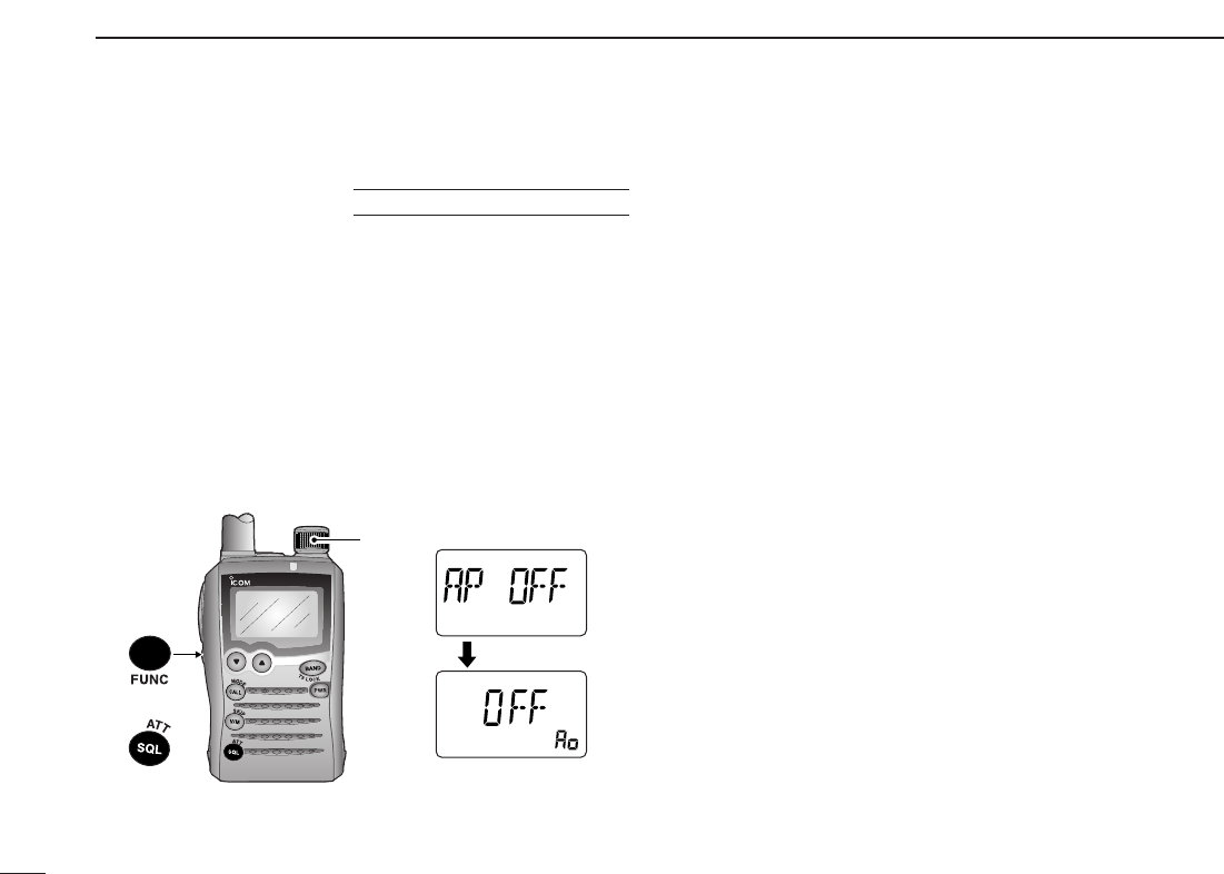
■Auto power-off function
The IC-P7A can be set to automatically turn OFF after a spec-
ified period in which no operation is performed.
120 min., 90 min., 60 min., 30 min. and OFF can be specified.
The specified period is retained even when the transceiver is
turned OFF by the auto power-off function. To cancel the
function, select “OFF” in step ebelow.
qWhile pushing and holding [FUNC], push and hold
[SQL] (
ATT
•
SET
)for 1 sec. to enter set mode.
wRotate [DIAL] to select “AP OFF.”
•Turn the expanded set mode ON for selection. (p. 39)
eWhile pushing and holding [FUNC], rotate [DIAL] to select
the desired time or to turn the function OFF.
rPush [SQL] (
ATT
•
SET
)to exit set mode.
■TV channel operation
TV channel operation is available only when TV channels are pro-
grammed using the optional CS-P7
CLONING SOFTWARE
. (p. 61)
DTV channel receiving
qPush [V/M] (
SKIP
•
S
.
MW
)to select VFO mode, if necessary.
wPush [BAND] (
TS
•
LOCK
)several times to select the TV
channel band.
•“tV” and channel number appear.
•While pushing and holding [BAND] (
TS
•
LOCK
), rotating [DIAL]
also selects the TV channel band.
eRotate [DIAL] to select the desired channel.
•While pushing and holding [FUNC], rotating [DIAL] selects the
all channels including skip channel.
DSkip channel setting
Unwanted channels can be skipped for rapid selection, etc.
qRotate [DIAL] to select the channel to be skipped.
•To clear the skip setting, rotate [DIAL] while pushing and holding
[FUNC] to select a skip channel.
wWhile pushing and holding [FUNC], push [V/M]
(
SKIP
•
S
.
MW
)to toggle the skip setting ON and OFF.
•“SKIP” appears when the channel is set as skip channel.
DAutomatic TV channel programming
TV channels can be programmed automatically.
➥Push and hold [CALL] (
MODE
•
SCAN
)for 1 sec. to start TV
channel programming.
•The programming will automatically stop when scanning all
channels.
SCAN
S.MW
SET
ATT
DTCS
TSQL
WFMAM -DUP
LOW
VOL PRIO P SK IP
MR
5
19
ATT
DTCS
TSQL
WFMAM -DUP
LOW
VOL PRIO P SK IP
MR
5
19
After 1 sec.
SET
[DIAL]
USING
EXPANDED SET MODE
64
11
OTHER FUNCTIONS
■Partial reset
If you want to initialize the operating conditions (VFO fre-
quency, VFO settings, set mode contents) without clearing
the memory contents, a partial reset function is available for
the transceiver.
➥While pushing and holding [FUNC] and [V/M] (
SKIP
•
S
.
MW
),
turn the power ON to partially reset the transceiver.
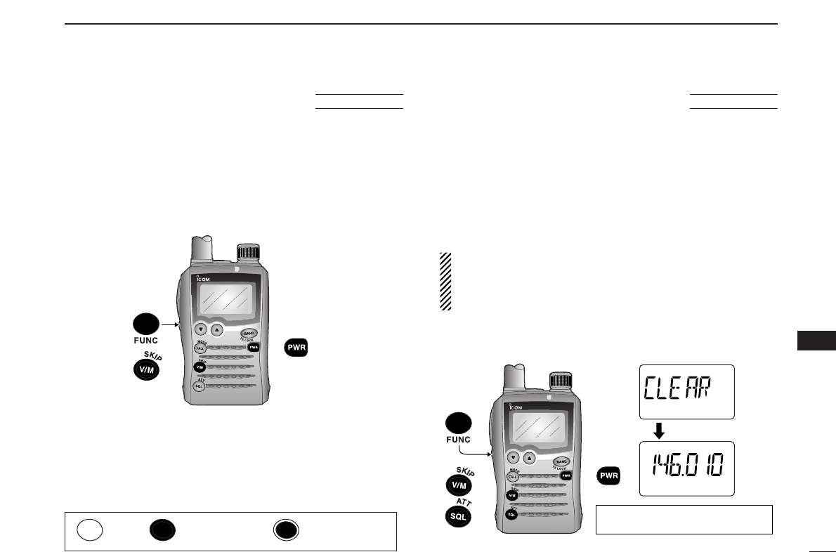
■All reset
The function display may occasionally display erroneous in-
formation (e.g. when first applying power). This may be
caused externally by static electricity or by other factors.
If this problem occurs, turn power OFF. After waiting a few
seconds, turn power ON again. If the problem persists, per-
form the following procedure.
•Partial resetting is also available. See left for details.
IMPORTANT!:
Resetting the transceiver CLEARS all memory information
and initializes all values in the transceiver, including TV
channel skip setting.
➥While pushing and holding [FUNC], [V/M] (
SKIP
•
S
.
MW
)and
[SQL] (
ATT
•
SET
), turn the power ON to reset the CPU.
SCAN
S.MW
SET
ATT
DTCS
TSQL
WFMAM -DUP
LOW
VOL PRIO P SK IP
MR
5
19
ATT
DTCS
TSQL
WFMAM -DUP
LOW
VOL PRIO P SK IP
MR
5
19
SET
S.MW
*The displayed frequency differs
according to tranceiver version.
AT
POWER ON
SCAN
S.MW
SET
S.MW
AT
POWER ON
11
Push Push and hold Dual operation

CH Freq.
40 628.75
41 636.75
42 644.75
43 652.75
44 660.75
45 668.75
46 676.75
47 684.75
48 692.75
49 700.75
50 708.75
51 716.75
52 724.75
53 732.75
54 740.75
55 748.75
56 756.75
57 764.75
58 772.75
59 780.75
60 788.75
61 796.75
62 804.75
63 812.75
64 820.75
65 828.75
66 836.75
67 844.75
68 852.75
69 860.75
CH Freq.
146.75
253.75
360.75
467.75
5180.75
6187.75
7194.75
8201.75
9208.75
10 215.75
11 222.75
12 229.75
21 476.75
22 484.75
23 492.75
24 500.75
25 508.75
26 516.75
27 524.75
28 532.75
29 540.75
30 548.75
31 556.75
32 564.75
33 572.75
34 580.75
35 588.75
36 596.75
37 604.75
38 612.75
39 620.75
■TV channels
The following tables show the channels versus
video and audio frequencies depending on each
version.
DDU.S.A. channels (unit: MHz)
CH Freq.
259.75
365.75
471.75
581.75
687.75
7179.75
8185.75
9191.75
10 197.75
11 203.75
12 209.75
13 215.75
14 475.75
15 481.75
16 487.75
17 493.75
18 499.75
19 505.75
20 511.75
21 517.75
22 523.75
23 529.75
24 535.75
25 541.75
26 547.75
CH Freq.
27 553.75
28 559.75
29 565.75
30 571.75
31 577.75
32 583.75
33 589.75
34 595.75
35 601.75
36 607.75
37 613.75
38 619.75
39 625.75
40 631.75
41 637.75
42 643.75
43 649.75
44 655.75
45 661.75
46 667.75
47 673.75
48 679.75
49 685.75
50 691.75
51 697.75
CH Freq.
52 703.75
53 709.75
54 715.75
55 721.75
56 727.75
57 733.75
58 739.75
59 745.75
60 751.75
61 757.75
62 763.75
63 769.75
64 775.75
65 781.75
66 787.75
67 793.75
68 799.75
69 805.75
DDCCIR channels (unit: MHz) DDAustralian channels
(unit: MHz)
CH Freq.
43 637.75
44 644.75
45 651.75
46 658.75
47 665.75
48 672.75
49 679.75
50 686.75
51 693.75
52 700.75
53 707.75
54 714.75
55 721.75
56 728.75
57 735.75
58 742.75
59 749.75
60 756.75
61 763.75
62 770.75
63 777.75
64 784.75
65 791.75
66 798.75
67 805.75
68 812.75
69 819.75
CH Freq.
051.75
162.75
269.75
391.75
4100.75
5107.75
5A 143.75
6180.75
7187.75
8194.75
9201.75
10 214.75
11 221.75
28 532.75
29 539.75
30 546.75
31 553.75
32 560.75
33 567.75
34 574.75
35 581.75
36 588.75
37 595.75
38 602.75
39 609.75
40 616.75
41 623.75
42 630.75
65
FREQUENCY TABLE
12

66
12
FREQUENCY TABLE
12
DDChina channels (unit: MHz)
CH Freq.
156.25
264.25
372.25
483.75
591.75
6174.75
7182.75
8190.75
9198.75
10 206.75
11 214.75
12 222.75
13 477.75
14 485.75
15 493.75
16 501.75
17 509.75
18 517.75
19 525.75
20 533.75
21 541.75
22 549.75
23 557.75
24 565.75
25 613.75
26 621.75
27 629.75
28 637.75
29 645.75
30 653.75
31 661.75
CH Freq.
32 669.75
33 677.75
34 685.75
35 693.75
36 701.75
37 709.75
38 717.75
39 725.75
40 733.75
41 741.75
42 749.75
43 757.75
44 765.75
45 773.75
46 781.75
47 789.75
48 797.75
49 805.75
50 813.75
51 821.75
52 829.75
53 837.75
54 845.75
55 853.75
56 861.75
57 869.75
58 877.75
59 885.75
60 893.75
61 901.75
62 909.75
CH Freq.
63 917.75
64 925.75
65 933.75
66 941.75
67 949.75
68 957.75
CH Freq.
150.75
260.75
367.75
4180.75
5187.75
6194.75
7201.75
8208.75
9215.75
10 222.75
11 229.75
DDNew
Zealand
channels
(unit: MHz)
CH Freq.
52 725.25
53 733.25
54 741.25
55 749.25
56 757.25
57 765.25
58 773.25
59 781.25
60 789.25
61 797.25
62 805.25
63 813.25
64 821.25
65 829.25
66 837.25
67 845.25
68 853.25
69 861.25
CH Freq.
21 477.25
22 485.25
23 493.25
24 501.25
25 509.25
26 517.25
27 525.25
28 533.25
29 541.25
30 549.25
31 557.25
32 565.25
33 573.25
34 581.25
35 589.25
36 597.25
37 605.25
38 613.25
39 621.25
40 629.25
41 637.25
42 645.25
43 653.25
44 661.25
45 669.25
46 677.25
47 685.25
48 693.25
49 701.25
50 709.25
51 717.25
DDUK channels (unit: MHz)
CH Freq.
43 653.75
44 661.75
45 669.75
46 677.75
47 685.75
48 693.75
49 701.75
50 709.75
51 717.75
52 725.75
53 733.75
54 741.75
55 749.75
56 757.75
57 765.75
58 773.75
59 781.75
60 789.75
61 797.75
62 805.75
63 813.75
64 821.75
65 829.75
66 837.75
67 845.75
68 853.75
69 861.75
CH Freq.
249.25
354.00
457.25
5182.50
6190.50
7198.50
8206.50
9214.50
10 222.50
21 477.75
22 485.75
23 493.75
24 501.75
25 509.75
26 517.75
27 525.75
28 533.75
29 541.75
30 549.75
31 557.75
32 565.75
33 573.75
34 581.75
35 589.75
36 597.75
37 605.75
38 613.75
39 621.75
40 629.75
41 637.75
42 645.75
DDFrench channels (unit: MHz)

67
12 FREQUENCY TABLE
DDIndonesian channels
(unit: MHz)
CH Freq.
253.75
360.75
467.75
5180.75
6187.75
7194.75
8201.75
9208.75
10 215.75
11 222.75
12 229.75
21 476.75
22 484.75
23 492.75
24 500.75
25 508.75
26 516.75
27 524.75
28 532.75
29 540.75
30 548.75
31 556.75
32 564.75
33 572.75
34 580.75
35 588.75
36 596.75
37 604.75
38 612.75
39 620.75
CH Freq.
40 628.75
41 636.75
42 644.75
43 652.75
44 660.75
45 668.75
46 676.75
47 684.75
48 692.75
49 700.75
50 708.75
51 716.75
52 724.75
53 732.75
54 740.75
55 748.75
56 756.75
57 764.75
58 772.75
59 780.75
60 788.75
61 796.75
62 804.75
63 812.75
64 820.75
65 828.75
66 836.75
67 844.75
68 852.75
69 860.75
DDItalian channels (unit: MHz)
CH Freq.
A59.25
B67.75
C87.75
D180.75
E188.75
F197.75
G206.75
H215.75
H1 222.75
H2 229.75
21 476.75
22 484.75
23 492.75
24 500.75
25 508.75
26 516.75
27 524.75
28 532.75
29 540.75
30 548.75
31 556.75
32 564.75
33 572.75
34 580.75
35 588.75
36 596.75
37 604.75
38 612.75
39 620.75
40 628.75
41 636.75
CH Freq.
42 644.75
43 652.75
44 660.75
45 668.75
46 676.75
47 684.75
48 692.75
49 700.75
50 708.75
51 716.75
52 724.75
53 732.75
54 740.75
55 748.75
56 756.75
57 764.75
58 772.75
59 780.75
60 788.75
61 796.75
62 804.75
63 812.75
64 820.75
65 828.75
66 836.75
67 844.75
68 852.75
69 860.75
DDTaiwan channels
(unit: MHz)
CH Freq.
7179.75
8185.75
9191.75
10 197.75
11 203.75
12 209.75
DDFOT channels
(unit: MHz)
CH Freq.
4181.75
5189.75
6197.75
7205.75
8213.75
9221.75

68
12
FREQUENCY TABLE
12
■VHF marine channels (unit: MHz)
CH Ship Ship
No. Transmit Receive
01 156.050 160.650
01A 156.050 156.050
02 156.100 160.700
03 156.150 160.750
03A 156.150 156.150
04 156.200 160.800
04A 156.200 156.200
05 156.250 160.850
05A 156.250 156.250
06 156.300 156.300
07 156.350 160.950
07A 156.350 156.350
08 156.400 156.400
09 156.450 156.450
10 156.500 156.500
11 156.550 156.550
12 156.600 156.600
13 156.650 156.650
14 156.700 156.700
15 156.750 156.750
16 156.800 156.800
17 156.850 156.850
18 156.900 161.500
18A 156.900 156.900
19 156.950 161.550
19A 156.950 156.950
20 157.000 161.600
20A 157.000 157.000
21 157.050 161.650
WX CH Frequency
01 162.550
02 162.400
03 162.475
04 162.425
05 162.450
06 162.500
07 162.525
08 161.650
09 161.775
10 163.275
CH Ship Ship
No. Transmit Receive
21A 157.050 157.050
21b 161.650 161.650
22 157.100 161.700
22A 157.100 157.100
23 157.150 161.750
23A 157.150 157.150
24 157.200 161.800
25 157.250 161.850
25b 161.850 161.850
26 157.300 161.900
27 157.350 161.950
28 157.400 162.000
28b 162.000 162.000
60 156.025 160.625
61 156.075 160.675
61A 156.075 156.075
62 156.125 160.725
62A 156.125 156.125
63 156.175 160.775
63A 156.175 156.175
64 156.225 160.825
64A 156.225 156.225
65 156.275 160.875
65A 156.275 156.275
66 156.325 160.925
66A 156.325 156.325
67 156.375 156.375
68 156.425 156.425
69 156.475 156.475
CH Ship Ship
No. Transmit Receive
70 156.525 156.525
71 156.575 156.575
72 156.625 156.625
73 156.675 156.675
74 156.725 156.725
77 156.875 156.875
78 156.925 161.525
78A 156.925 156.925
79 156.975 161.575
79A 156.975 156.975
80 157.025 161.625
80A 157.025 157.025
81 157.075 161.675
81A 157.075 157.075
82 157.125 161.725
82A 157.125 157.125
83 157.175 161.775
83A 157.175 157.175
83b 161.775 161.775
84 157.225 161.825
84A 157.225 157.225
85 157.275 161.875
85A 157.275 157.275
86 157.325 161.925
86A 157.325 157.325
87 157.375 161.975
87A 157.375 157.375
88 157.425 162.025
88A 157.425 157.425
■Weather channels(unit: MHz)

69
12 FREQUENCY TABLE
CH Frequency
1462.5625 MHz
2462.5875 MHz
3462.6125 MHz
4462.6375 MHz
5462.6625 MHz
6462.6875 MHz
7462.7125 MHz
■Other communications in the USA
DDFRS (Family Radio Service) channels
Dot color Frequency
Red 151.625 MHz
Purple 151.955 MHz
Blue 154.570 MHz
Green 154.600 MHz
White 462.575 MHz
Black 462.625 MHz
Orange 462.675 MHz
Brown 464.500 MHz
Yellow 464.550 MHz
“J” Dot 467.763 MHz
“K” Dot 467.813 MHz
Silver Star 467.850 MHz
Gold Star 467.875 MHz
Red Star 467.900 MHz
Blue Star 467.925 MHz
Transceiver Transceiver
Receive transmit
462.5500 MHz 467.5500 MHz
462.5625 MHz
462.5750 MHz 467.5750 MHz
462.5875 MHz
462.6000 MHz 467.6000 MHz
462.6125 MHz
462.6250 MHz 467.6250 MHz
462.6375 MHz
462.6500 MHz 467.6500 MHz
462.6625 MHz
462.6750 MHz 467.6750 MHz
462.6875 MHz
462.7000 MHz 467.7000 MHz
462.7125 MHz
462.7250 MHz 467.7250 MHz
CH Frequency
1151.820 MHz
2151.880 MHz
3151.940 MHz
4154.570 MHz
5154.600 MHz
CH Frequency
126.965 MHz
226.975 MHz
326.985 MHz
427.005 MHz
527.015 MHz
627.025 MHz
727.035 MHz
827.055 MHz
927.065 MHz
10 27.075 MHz
11 27.085 MHz
12 27.105 MHz
13 27.115 MHz
14 27.125 MHz
15 27.135 MHz
16 27.155 MHz
17 27.165 MHz
18 27.175 MHz
19 27.185 MHz
20 27.205 MHz
DDBRS (Business Radio
Service) channels
DDGMRS (General Mobile
Radio Service) channels
DDMURS channels
DDHF CB (Citizens Band) channels
CH Frequency
21 27.215 MHz
22 27.225 MHz
23 27.255 MHz
24 27.235 MHz
25 27.245 MHz
26 27.265 MHz
27 27.275 MHz
28 27.285 MHz
29 27.295 MHz
30 27.305 MHz
31 27.315 MHz
32 27.325 MHz
33 27.335 MHz
34 27.345 MHz
35 27.355 MHz
36 27.365 MHz
37 27.375 MHz
38 27.385 MHz
39 27.395 MHz
40 27.405 MHz
CH Frequency
8467.5625 MHz
9467.5875 MHz
10 467.6125 MHz
11 467.6375 MHz
12 467.6625 MHz
13 467.6875 MHz
14 467.7125 MHz

70
12
FREQUENCY TABLE
12
Frequency Description
121.500 Emergencies
122.000 Flight Advisory Service
122.200 Flight Service Stations
122.700 Unicom— Uncontrolled airports
122.725 Unicom— Private airports
122.750 Unicom— Air-to-air communications
122.800 Unicom— Uncontrolled airports
122.900 Search & rescue training, & uncontrolled airports
122.950 Unicom— Controlled airports
123.000 Unicom— Uncontrolled airports
123.025 Helicopters— Air-to-air communications
123.050 Unicom— Heliports
123.075 Unicom— Heliports
123.100 Search & Rescue
123.300 Flight Schools
123.450 Air-to-air communications (unofficial)
123.500 Flight Schools
123.600 Flight Service Stations— Uncontrolled airports
148.125 Civil Air Patrol Repeaters— Secondary
148.150 Civil Air Patrol Repeaters— Primary
156.300 Aircraft-to-ship— safety
156.400 Aircraft-to-ship— commercial
156.425 Aircraft-to-ship— non-commercial
156.450 Aircraft-to-ship— commercial
156.625 Aircraft-to-ship— non-commercial
156.900 Aircraft-to-ship— commercial
243.000 Military Emergency “Guard”
255.400 Flight Advisory Service
257.800 Civilian Towers
311.000 SAC Primary
321.000 SAC Secondary
381.800 USCG— Primary
DDGeneral aviation frequencies (unit: MHz)
CH
Frequency
Remarks
range
2– 13 54–216 (same as broadcast VHF)
14– 22 120–174 Mid band Ch. A–I
23– 36 216–300 Super band J–W
37– 53 300–402 Hyper band AA–QQ
54– 64 402–468
65– 94 468–648 (Ultra band)
95– 99 90–120 Low band A5–A1
100–125 648–804 (Ultra band)
DDCable TV (IRC) (unit: MHz)
169.445 MHz
169.505 MHz
170.245 MHz
170.305 MHz
171.045 MHz
171.105 MHz
171.845 MHz
171.905 MHz
*Power limited to 1/20 watt. These frequencies are also used at drive-in win-
dows at some fast-food restaurants.
DDWireless Microphones

71
12 FREQUENCY TABLE
■Other communications— other countries
CH Frequency
1446.00625
2446.01875
3446.03125
4446.04375
5446.05625
6446.06875
7446.08125
8446.09375
DD
PMR446 channels
(unit: MHz)
CH Frequency
59 434.525
60 434.550
61 434.575
62 434.600
63 434.625
64 434.650
65 434.675
66 434.700
67 434.725
68 434.750
69 434.775
CH Frequency
1433.075
2433.100
3433.125
4433.150
5433.175
6433.200
7433.225
8433.250
9433.275
10 433.300
11 433.325
12 433.350
13 433.375
14 433.400
15 433.425
16 433.450
17 433.475
18 433.500
19 433.525
20 433.550
21 433.575
22 433.600
23 433.625
24 433.650
25 433.675
26 433.700
27 433.725
28 433.750
29 433.775
DDLPD (Low Power Device) channels (unit: MHz)
CH Frequency
30 433.800
31 433.825
32 433.850
33 433.875
34 433.900
35 433.925
36 433.950
37 433.975
38 434.000
39 434.025
40 434.050
41 434.075
42 434.100
43 434.125
44 434.150
45 434.175
46 434.200
47 434.225
48 434.250
49 434.275
50 434.300
51 434.325
52 434.350
53 434.375
54 434.400
55 434.425
56 434.450
57 434.475
58 434.500

72
12
FREQUENCY TABLE
12
CH Frequency
1476.425 MHz
2476.450 MHz
3476.475 MHz
4476.500 MHz
5476.525 MHz
6476.550 MHz
7476.575 MHz
8476.600 MHz
9476.625 MHz
10 476.650 MHz
11 476.675 MHz
12 476.700 MHz
13 476.725 MHz
14 476.750 MHz
15 476.775 MHz
16 476.800 MHz
17 476.825 MHz
18 476.850 MHz
19 476.875 MHz
20 476.900 MHz
DDUHF C.R.S (Citizen Radio Service) channels
CH Frequency
21 476.925 MHz
22 476.950 MHz
23 476.975 MHz
24 477.000 MHz
25 477.025 MHz
26 477.050 MHz
27 477.075 MHz
28 477.100 MHz
29 477.125 MHz
30 477.150 MHz
31 477.175 MHz
32 477.200 MHz
33 477.225 MHz
34 477.250 MHz
35 477.275 MHz
36 477.300 MHz
37 477.325 MHz
38 477.350 MHz
39 477.375 MHz
40 477.400 MHz

73
MAINTENANCE
13
PROBLEM POSSIBLE CAUSE SOLUTION REF.
■Troubleshooting If your transceiver seems to be malfunctioning, please check
the following points before sending it to a service center.
No power comes on.
No sound comes from the
speaker.
Sensitivity is low and only
strong signals are audible.
Frequency cannot be set.
No beep sound.
Receive audio is distorted.
Transmitting is impossible.
No contact possible with
another station.
Repeater cannot be ac-
cessed.
•The batteries are exhausted.
•The battery polarity is reversed.
•Volume level is too low.
•Squelch level is set too tight.
•Different tone is selected with tone/DTCS
squelch.
•Attenuator function is activated.
•The lock function is activated.
•Beep tones are turned OFF or the beep tone level
is too low.
•The operating mode is not selected correctly.
•The battery pack is exhausted.
• A frequency outside of the 144/440 MHz amateur
bands is set
•The other station is using tone squelch.
• The transceiver is set to duplex
•Wrong offset frequency is programmed.
• Priority watch is paused on the watching fre-
quency
•Charge the battery pack.
•Check the battery polarity.
•Push [YY]to obtain a suitable level.
•While pushing and holding [SQL], rotate [DIAL] to
set the squelch level.
•Turn the appropriate function OFF.
•While pushing and holding [FUNC], push [SQL]
momentarily to turn the attenuator function OFF.
•While pushing and holding [FUNC], push and hold
[BAND] for 1 sec. to turn the function OFF.
•Turn beep tone ON or set the beep tone level to ap-
propriate level in set mode.
•While pushing and holding [FUNC], push [CALL]
several times to select a suitable operating mode.
•Charge the battery pack.
• Set the frequency within the 144/440 MHz amateur
bands.
•Turn the tone squelch function ON.
• Set to simplex.
•Correct the offset frequency.
• Correct the subaudible tone frequency
p. 6
p. 6
p. 13
p. 14
p. 45
p. 15
p. 18
p. 54
p. 14
p. 6
pgs. 9,
11
p. 45
p. 19
p. 20
p. 21
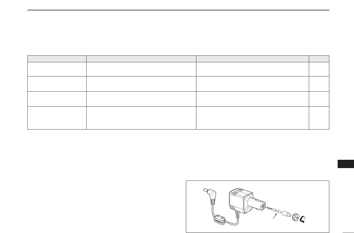
74
13
MAINTENANCE
13
PROBLEM POSSIBLE CAUSE SOLUTION REF.
Desired set mode item
cannot be selected.
Programmed scan does
not start.
Memory or bank scan
does not start.
Charging indicator (BC-
164) lights red while
charging.
•“EXPAND” item is set to OFF.
•Program scan edges are not programmed.
•No or only one memory or bank channel is pro-
grammed.
•The temperature is too hot or too cold around the
charger (BC-164).
•Turn “EXPAND” item ON.
•Program a pair of scan edge channels.
•Program at least 2 memory or bank channels
•Place the charger within the specified temperature
range (+5°C to +35°C; +41°F to +95 °F), then
charge the battery pack.
p. 49
p. 36
pgs. 24,
25
p. 8
If the fuse blows or the charger stops functioning while oper-
ating with the optional CP-21LR, find the source of the prob-
lem if possible, and replace the damaged fuse with a new,
rated one (FGB 2 A) as shown at right.
Fuse 2 A
■Optional CP-21LR fuse replacement
Troubleshooting (continued)
75
SPECIFICATIONS
14
■Transceiver
DGeneral
•Frequency coverage : (unit: MHz)
*1Guaranteed 440–450 MHz only, *2Guaranteed 144–148 MHz only
*3Guaranteed 430–440 MHz only,
*4Guaranteed receiving ranges are same as transmit ranges
•Mode : FM, AM (Rx only), WFM (Rx only)
•No. of memory channels : 1250 (incl. 50 scan edges, 200 auto
memory write channels)
•No. of call channels : 2 channels
•Usable temp. range : –10°C to +60°C; +14°F to +140°F
•Tuning steps : 5, 6.25, 8.33, 9, 10, 12.5, 15, 20, 25,
30, 50, 100 and 200 kHz
•Frequency stability : ±6 ppm (–10°C to +60°C;+14°F to +140°F)
•Power supply : Specified battery pack (3.7 V DC)
•Current drain (at 3.7 V DC) :
Tx High 144, 440 MHz Less than 1.5 A
Tx Low 144 MHz 0.4 A (approx.)
440 MHz 0.5 A (approx.)
Rx rated audio Less than 150 mA
standby 80 mA (approx.)
•Antenna connector : SMA (50 Ω)
•
External MIC/SP connector
:3-conductor 3.5(d) mm; 1⁄8˝
8 Ω(SP)/2 kΩ(MIC)
•Dimensions : 47(W)×81(H)×28(D) mm;
(projections not included) 127⁄32(W)×33⁄16(H)×13⁄32(D) in
•Weight (approx.) :160 g; 5.64 oz
(with antenna and BP-243)
DReceiver
•Receive system : Double-conversion superheterodyne
•Intermediate frequencies : 1st 46.35 MHz (FM/AM)
14.85 MHz (WFM)
2nd 450 kHz
•Sensitivity : (except spurious points)
FM (at 12 dB SINAD)
30.000–89.995 MHz Less than 0.45 µV
90.000–143.995 MHz Less than 0.2 µV
144.000–147.995 MHz Less than 0.18 µV
148.000–179.995 MHz Less than 0.2 µV
350.000–470.000 MHz 0.18 µV (typical)
600.000–939.990 MHz Less than 1.4 µV
940.000–999.990 MHz Less than 2.5 µV
U.S.A
Canada
Australia
Korea
Taiwan
General
Transmit
144–148, 430–450*1
144–148, 430–450*1
144–148, 420–450*3
144–146, 430–440
144–146, 430–432
136–173.995*2,
400–478.995*3
Receive*4
0.495–821.990,
851–866.990,
896–999.990
0.495–999.990
0.495–999.990
144–146, 430–440
144–146, 430–432
0.495–999.990
All stated specifications are subject to change without notice or obligation.

■Battery pack (BP-243)
•Capacity : 1800 mAh
•Battery voltage : 3.7 V
•Charging temp. range : 0°C to +40°C; +32°F to +104°F
•Usable temp. range : –20°C to +60°C; –4°F to +140°F
•Storage temp. range :
Within 1 month –20°C to +50°C; –4°F to +122°F
Within 3 months –20°C to +35°C; –4°F to +95°F
Within 1 year –20°C to +20°C; –4°F to +68°F
•Dimensions : 35.3(W)×11.4(H)×53.1(D) mm;
(projections not included) 13⁄8(W)×7⁄16(H)×23⁄32(D) in
•Charging period (approx.) :3 hrs.
•Battery life*1(approx.) :20 hrs.
*1Operating periods are calculated under the following conditions;
Tx : Rx : standby =5 : 5 : 90, power save function: auto setting is activated
■Battery charger (BC-164)
•Power supply : 12 to 16 V DC or the specified Icom
AC adapter (BC-145LA/LE/LV)
•Charging current : 760 mA±10%
•End voltage : 4.2 V±0.1 V
•Charging temp. range : +5°C to +35°C; +41°F to +95 °F
•Dimensions : 67(W)×86.5(H)×50(D) mm;
(projections not included) 25⁄8(W)×313⁄32(H)×131⁄32(D) in
•Weight (approx.) :95 g; 3.4 oz
76
14
SPECIFICATIONS
14
AM (at 10 dB S/N)
0.495–4.995 MHz Less than 2.2 µV
5.000–29.995 MHz Less than 1.4 µV
118.000–136.995 MHz Less than 1.4 µV
WFM (at 12 dB SINAD)
76.000–107.995 MHz Less than 1.8 µV
600–799.990 MHz Less than 2.5 µV
•Selectivity :
FM, AM More than 12 kHz/6 dB
Less than 30 kHz/60 dB
WFM More than 150 kHz/10 dB
Less than 700 kHz/20 dB
•Spurious and image rejection ratio:
More than 40dB
•Audio output power : More than 50 mW at 10%
(at 3.7 V DC) distortion with an 8 Ωload
DTransmitter
•Modulation system : Variable reactance frequency
modulation
•Output power (at 3.7 V DC) :
144 MHz High 1.5 W, Low 0.1 W (approx.)
440 MHz High 1.0 W, Low 0.1 W (approx.)
•Max. frequency deviation : ±5.0 kHz
•Spurious emissions : Less than –60 dB (High power)
Less than –50 dB (Low power)
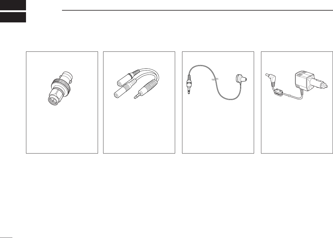
77
OPTIONS
15
■Options
CP-21LR
CIGARETTE LIGHTER
CABLE WITH NOISE FILTER
Allows you to charge the trans-
ceiver using supplied BC-164
BATTERY CHARGER
.
OPC-782
PLUG ADAPTER CABLE
Used for connection with an
Icom speaker-microphone or
earphone.
AD-92SMA
ANTENNA
CONNECTOR ADAPTER
Allows you to connect an exter-
nal antenna with a BNC con-
nector.
SP-13
EARPHONE
Provides clear receive audio in
noisy environments. An optional
OPC-782 is required for con-
nection.
BP-243
LI
-
ION BATTERY PACK
3.7 V/1800 mAh Lithium Ion bat-
tery pack. Same as supplied one.
OPC-474
CLONING CABLE
For connection between trans-
ceivers for data cloning.
CS-P7
CLONING SOFTWARE
+ OPC-478U
CLONING CABLE
(USB type)
Allows you to transfer data, such
as memories, and quickly and
easily edit and store data via a
PC (for Microsoft®Windows®
98/Me/2000/XP). Current RS-
232C (DB 9-pin) type cloning
cable, OPC-478, is also available.
BC-145LA/LE/LV
AC ADAPTER
Same as supplied AC adapter
with BC-164. (Not supplied with
some versions)
Regularly charges the installed
battery pack into transceiver.
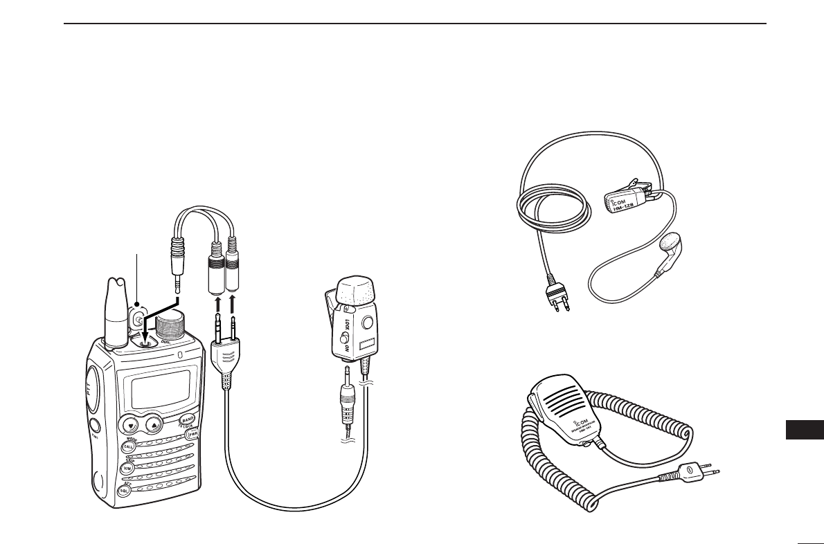
78
15
OPTIONS
15
DDHM-153
EARPHONE MICROPHONE
An optional OPC-782 is required for connection.
DDHM-128
EARPHONE MICROPHONE
An optional OPC-782 is required for connection.
DDHM-131
SPEAKER MICROPHONE
An optional OPC-782 is required for connection.
HM-131
HM-128
SCAN
SET
S.MW
Microphone
OPC-782
HM-153
Speaker/MIC
connector
[MIC/SP]
cap
NOTE: Connect the OPC-782 after removing
the [MIC/SP] cap (MIC/SP jack cover).
Keep the [MIC/SP] cap attached when jack
are not in use to keep the contact clean.
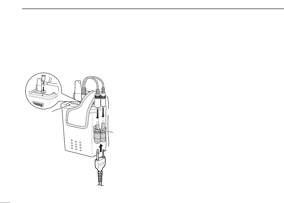
79
15 OPTIONS
DDLC-161
CARRYING CASE
Helps protect the transceiver from scratches, etc.
Tension
release loop
LC-161
Transceiver
OPC-782
NOTE: When using as below illustration,
tension release loop protects the [MIC/SP]
connector from being damaged by cable
stress or vibration
e
w
q
16
POCKET GUIDE
Important operating instructions are summed up in
this and the following page for your simple reference.
By cutting along the line and folding on the dotted
line, it will become a card sized operating guide which
can easily be carried in a card case or wallet, etc.
q Cut w Fold r Completee Fold
80
q
w
e
r
iP7A
■ VFO and memory mode selection
POCKET GUIDE
Push [V/M] to toggle between
VFO
and
memory mode
.
➥
■ Operating mode selection
While pushing and holding
[FUNC], push [CALL] several
times to select the desired
mode.
➥
■ Audio level setting
Push [Y] to increase, push [Z]
to decrease the audio level.
➥
■ Squelch level setting
While pushing [SQL], rotate
[DIAL] to set the squelch level.
➥
■ Frequency band selection
Push [BAND] several times, or
while pushing and holding
[BAND], rotate [DIAL] to select
the desired frequency band.
➥
■ Tuning step selection
While pushing and holding [FUNC],
push [BAND] to enter tuning step
selection. Then rotate [DIAL] to
select the desired tuning step.
• Push [BAND] again to return to the
previous condition.
➥
■ Monitor function
Push and hold [SQL].
• The 1st segment of S/RF meter blinks.
➥
■ Key lock function
While pushing and holding [FUNC],
push [BAND] for 1 sec. to toggle
the key lock function ON and OFF.
• “ L ” appears when the lock function is
in use.
➥
■ Set mode setting
While pushing and holding
[FUNC], push and hold [SQL]
for 1 sec. to enter
set mode
.
Rotate [DIAL] to select the de-
sired item.
While pushing and holding
[FUNC], rotate [DIAL] to set
the desired value or condition.
Push [SQL] to exit
set mode
.
q
w
■ Frequency setting
Push [V/M] to select
VFO
mode
.
Rotate [DIAL] to set the de-
sired operating frequency.
• While pushing [FUNC], dial rota-
tion changes frequency in 1 MHz
steps.
q
w
■ Memory channel selection
Push [V/M] to select
memory
mode
.
Rotate [DIAL] to set the de-
sired memory channel.
• While pushing [FUNC], dial rota-
tion changes memory channel in
10 channels steps.
■ Attenuator function
While pushing and holding
[FUNC], push [SQL] to toggle
the attenuator function ON and
OFF.
• “ATT” appears when the attenuator
function is in use.
➥
■ Transmit power setting
While pushing and holding
[FUNC], push [PTT] to toggle
the transmit output power High
and Low.
• “LOW” appears when the low out-
put power is selected.
➥
<CUT HERE>
<CUT HERE>
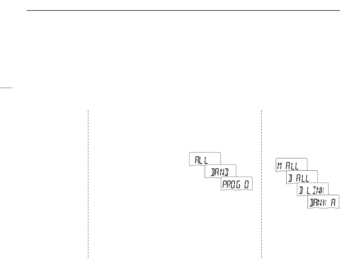
81
16 POCKET GUIDE
q
w
e
■ Memory bank channel selection
Push [V/M] to select
memory
mode
.
Push [BAND] several times, or
while pushing and holding
[BAND], rotate [DIAL] to select
the desired bank group.
Rotate [DIAL] to select the de-
sired bank channel.
q
w
■ Call channel selection
Push [CALL] to select
call
channel mode
.
Rotate [DIAL] to select the de-
sired call channel.
• Push [CALL] again or push [V/M] to
return to the previous condition.
q
w
e
r
■ Memory channel programming
Set the desired frequency and
other functions in
VFO mode
.
Push and hold [V/M] for 1 sec.
to enter
select memory write
mode
.
• 1 short and 1 long beeps sound.
Rotate [DIAL] to select the de-
sired memory channel number.
Push and hold [V/M] for 1 sec.
again to program the contents
into the selected channel.
• 3 beeps sound.
q
w
e
■ Scan skip setting
Push [V/M] to select
memory
mode
.
Rotate [DIAL] to select the de-
sired memory channel.
While pushing and holding
[FUNC], push [V/M] to set the
skip setting (skip channel or
skip frequency) ON and OFF.
q
w
■ VFO scans
Push [V/M] to select
VFO
mode
.
Push and hold [CALL] for 1 sec.
• One of scan type “ALL,” “BAND” or
“PROG xx” (xx= 0–24) appears.
e
r
Rotate [DIAL] to select the de-
sired scan type. Push [CALL]
again to start the scan.
• Rotate [DIAL] to change the scan-
ning direction.
• During scan, push [V/M] to start auto
memory write scan.
Push [CALL] again to stop the
scan.
e
r
Rotate [DIAL] to select the de-
sired scan type. Push [CALL]
again to start the scan.
• Rotate [DIAL] to change the scan-
ning direction.
Push [CALL] again to stop the
scan.
q
w
■ Memory scans
Push [V/M] to select
memory
mode
.
Push and hold [CALL] for 1 sec.
• One of scan type “M ALL,” “B ALL,”
“B LINK” or “BANK” appears, if
memory banks are assigned.

82
MEMO