ICOM orporated 296400 Scanning Receiver User Manual
ICOM Incorporated Scanning Receiver Users Manual
UserManual.wiki
>
ICOM orporated
>
296400 User Manual
Users Manual
Navigation menu
Upload a User Manual
Namespaces
Wiki Guide
HTML
PDF
Info
Views
User Manual
Discussion / Help
Navigation
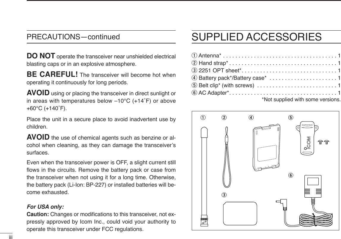
![iFOREWORDThank you for purchasing this Icom transceiver. The IC-V85FM TRANSCEIVERis designed and built with Icom’s superiortechnology and craftsmanship. With proper care, this trans-ceiver should provide you with years of trouble-free operation.We want to take a couple of moments of your time to thankyou for making the IC-V85 your radio of choice, and hope youagree with Icom’s philosophy of “technology first.” Many hoursof research and development went into the design of your IC-V85.DDFEATURES❍7W*— high transmit output power *7 W : IC-V85 except [THA] version,5.5 W : IC-V85 [THA] version❍CTCSS and DTCS encoder/decoder stan-dard❍Optional DTMF decoderIMPORTANTREAD ALL INSTRUCTIONS carefully and completelybefore using the transceiver.SAVE THIS INSTRUCTION MANUAL— This in-struction manual contains important operating instructions forthe IC-V85.EXPLICIT DEFINITIONSWORD DEFINITIONRWARNING!CAUTIONNOTEPersonal injury, fire hazard or electric shockmay occur.Equipment damage may occur.Recommended for optimum use. No risk ofpersonal injury, fire or electric shock.Icom, Icom Inc. and the logo are registered trademarks of IcomIncorporated (Japan) in the United States, the United Kingdom, Ger-many, France, Spain, Russia and/or other countries.](https://usermanual.wiki/ICOM-orporated/296400/User-Guide-745010-Page-2.png)
![iiRWARNING RF EXPOSURE! This device emitsRadio Frequency (RF) energy. Extreme caution should be ob-served when operating this device. If you have any questionsregarding RF exposure and safety standards please refer tothe Federal Communications Commission Office of Engi-neering and Technology’s report on Evaluating Compliancewith FCC Guidelines for Human Radio frequency Electro-magnetic Fields (OET Bulletin 65)RWARNING! NEVER hold the transceiver so that theantenna is very close to, or touching exposed parts of thebody, especially the face or eyes, while transmitting. Thetransceiver will perform best if the microphone is 5 to 10 cm(2 to 4 inches) away from the lips and the transceiver is verti-cal.RWARNING! NEVER operate the transceiver with aheadset or other audio accessories at high volume levels.Hearing experts advise against continuous high volume op-eration. If you experience a ringing in your ears, reduce thevolume or discontinue use.RWARNING! NEVER operate the transceiver whiledriving a vehicle. Safe driving requires your full attention—anything less may result in an accident.RWARNING! NEVER connect the transceiver to an ACoutlet. This may pose a fire hazard or result in an electric shock.NEVER connect a power supply of more than 16 V DCthrough the optional CP-19R CIGARETTE LIGHTER CABLEto the[DC 11V] jack to prevent damaging the transceiver.NEVER connect the transceiver to a power source usingreverse polarity. This will ruin the transceiver.NEVER cut the DC power cable between the DC plug andfuse holder. If an incorrect connection is made after cutting,the transceiver may be damaged.NEVER expose the transceiver to rain, snow or any liquids.The transceiver may be damaged.NEVER operate or touch the transceiver with wet hands.This may result in an electric shock or ruin the transceiver.NEVER attempt to charge alkaline or dry cell batteries. Beaware that external DC power connections will charge batter-ies inside the battery case. This will damage not only the bat-tery case but also the transceiver.DO NOT push the PTT when not actually desiring to trans-mit.PRECAUTIONS](https://usermanual.wiki/ICOM-orporated/296400/User-Guide-745010-Page-3.png)
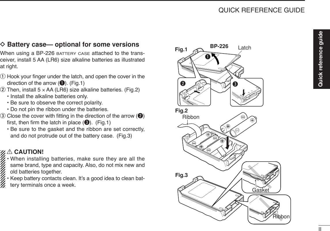
![IQUICK REFERENCE GUIDE■PreparationDAntennaAttach the antenna to the transceiveras illustrated at right.DBelt clip Conveniently attaches to your belt.Attach the belt clip with the supplied screws using a phillipsscrewdriver.DBattery pack replacementBefore replacing the battery pack, push and hold [PWR] for 1sec. to turn the power OFF.• To attach the battery packSlide the battery pack on the back of the transceiver in the di-rection of the arrow (q), then lock it with the battery releasebutton.•Slide the battery pack until the battery release button makes a ‘click’sound.• To release the battery packPush the battery release button in the direction of the arrow(w) as shown below. The battery pack is then released.wqBattery packBattery release buttonTo attach the belt clip](https://usermanual.wiki/ICOM-orporated/296400/User-Guide-745010-Page-8.png)
![IIIQUICK REFERENCE GUIDEDDRegular chargingWhen using a BP-227 BATTERY PACKattached to the trans-ceiver, prior to using the transceiver for the first time, the bat-tery pack must be fully charged for optimum life andoperation.DDCharging note•Be sure to turn the transceiver power OFF.Otherwise the battery pack will not be charged completely or takeslonger charging time periods.•External DC power operation becomes possible when usingan optional CP-19R. The attached battery pack is alsocharged simultaneously, except during transmit. (see p. 16for more details)Even through there is no indication during regular charg-ing, the transceiver automatically stops charging the bat-tery pack when the battery pack is fully charged (BP-227’svoltage becomes approx. 7.2 V) or the continuous charg-ing time is over 15 hours.• BC-167A/D• CP-19R (Optional)to AC outletto cigarette lightersocket (12 V DC)Transceiverto [DC 11V]Turn power OFF while charging the battery pack.• Charging time period: Approx. 12–13 hours](https://usermanual.wiki/ICOM-orporated/296400/User-Guide-745010-Page-10.png)
![■Your first contactNow that you have your IC-V85 ready, you are excited to geton the air. We would like to walk you through a few basic op-erational steps to make your first “On The Air” use an enjoy-able experience.DAbout default settingThe [VOL] control function can be exchanged with [YY]/[ZZ]keys function in INITIAL SET MODE. However, in this QUICKREFERENCE, the factory default setting ([VOL] controlsaudio output level) is used to simplify instructions.DBasic operation1. Turning ON the transceiverAlthough you have purchased a brand new transceiver, somesettings may be changed from the factory defaults becauseof the Quality Controlprocess. Resetting the CPUis necessary to start fromfactory default.➥While pushing [MONI]and [CLR], push andhold [PWR] for 1 sec. toreset the CPU and turnpower ON.2. Adjusting audio output level➥Rotate [VOL] to set the desiredaudio level.3. Adjusting the squelch level➥While pushing and holding[MONI], push [YY]or [ZZ]to setthe squelch level.4. Tune the desired frequencyThe up/down keys, [YY]/[ZZ], willallow you to tune to the frequencythat you want to operate on. Page18 will instruct you on how to adjustthe tuning step size.➥Push [YY]or [ZZ]to adjust the fre-quency.IVQUICK REFERENCE GUIDEDUP SCANPRIOSETH/M/LOPTSKIPBANKTONET.SCANP.BEEPABDCCALLENTMR CLRFUNCPWR9874123560CLRDMONIPWRDUP SCANPRIOSETH/M/LOPTSKIPBANKTONET.SCANP.BEEPABDCCALLENTMR CLRFUNCPWR9874123560MONI[VOL]DUP SCANPRIOSETH/M/LOPTSKIPBANKTONET.SCANP.BEEPABDCCALLENTMR CLRFUNCPWR9874123560Quick reference guide](https://usermanual.wiki/ICOM-orporated/296400/User-Guide-745010-Page-11.png)
![VQUICK REFERENCE GUIDEDirect frequency input from thekeypad is also available. ➥To enter the desired frequency,enter 6 digits starting from the100 MHz digit.•Entering three* to five digits thenpushing [✱ENT]will also set the fre-quency. (*Some versions only re-quires two digits.)•When a digit is mistakenly input,push [CLR] to abort input.5. Transmit and receive ➥Push and hold [PTT] to transmit, then speak into the mi-crophone; release to receive.■Repeater operation1. Setting duplex➥Push [FUNC], then [DUP](4) sev-eral times to select minus duplexor plus duplex.•The USA version has an auto re-peater function, therefore, setting du-plex is not required.2. Repeater tone➥Push [FUNC], then [TONE](1) sev-eral times until “ ” appears, if re-quired.DUP SCANPRIOSETH/M/LOPTSKIPBANKTONET.SCANP.BEEPABDCCALLENTMR CLRFUNCPWR9874123560AFUNC1TONEDUP SCANPRIOSETH/M/LOPTSKIPBANKTONET.SCANP.BEEPABDCCALLENTMR CLRFUNCPWR9874123560A4FUNCDUP• Example 1— when entering 145.525 MHzPush• Example 2— when entering 144.800 MHzPush1TONE4DUP1TONE4DUP4DUP2P.BEEP5SCAN5SCAN5SCAN8SET0OPTENTDUP SCANPRIOSETH/M/LOPTSKIPBANKTONET.SCANP.BEEPABDCCALLENTMR CLRFUNCPWR9874123560ENTDCLRKeypad](https://usermanual.wiki/ICOM-orporated/296400/User-Guide-745010-Page-12.png)
![VIQUICK REFERENCE GUIDEQuick reference guideThe IC-V85 has a total of 107 memory channels (including 6scan edges and 1 call channel) for storing often used operat-ing frequency, repeater settings, etc.1. Setting frequencyIn VFO mode, set the desired operating frequency with otherdesired settings, such as repeater and subaudible tone.2. Selecting a memory channel➥Push [FUNC] and [MR] then push[YY] or [ZZ]several times to selectthe desired memory channel.•“X” indicator and memory channelnumber blink.3. Writing a memory channel➥Push [FUNC], then push and hold[MR] for 1 sec. to program.•3 beeps sound.•Continue to push and hold [MR] for 1 sec. after 3 beeps are emit-ted, to increment the displayed memory channel number.DUP SCANPRIOSETH/M/LOPTSKIPBANKTONET.SCANP.BEEPABDCCALLENTMR CLRFUNCPWR9874123560AFUNCCMRDUP SCANPRIOSETH/M/LOPTSKIPBANKTONET.SCANP.BEEPABDCCALLENTMR CLRFUNCPWR9874123560AFUNCCMR■Programming memory channels](https://usermanual.wiki/ICOM-orporated/296400/User-Guide-745010-Page-13.png)
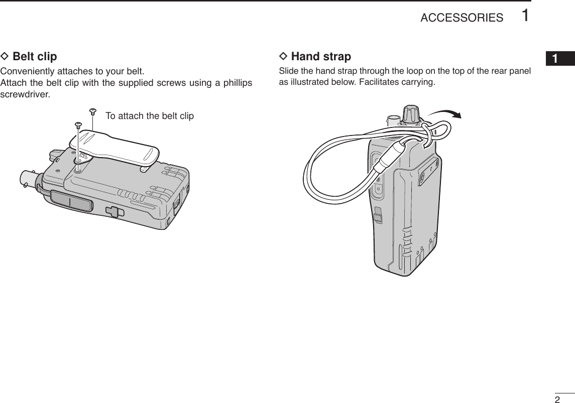
![1ACCESSORIES1■Accessory attachmentDAntennaAttach the antenna to the transceiver as illustrated below. Keep the [SP/MIC] cap (SP/MIC jack cover) attached whenjacks are not in use to keep the contacts clean.Attach the[SP/MIC] cap.[SP/MIC] cap](https://usermanual.wiki/ICOM-orporated/296400/User-Guide-745010-Page-14.png)
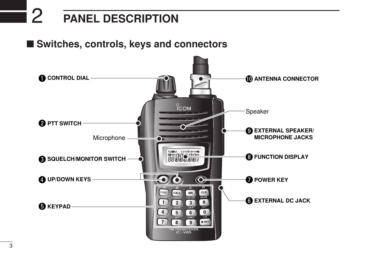
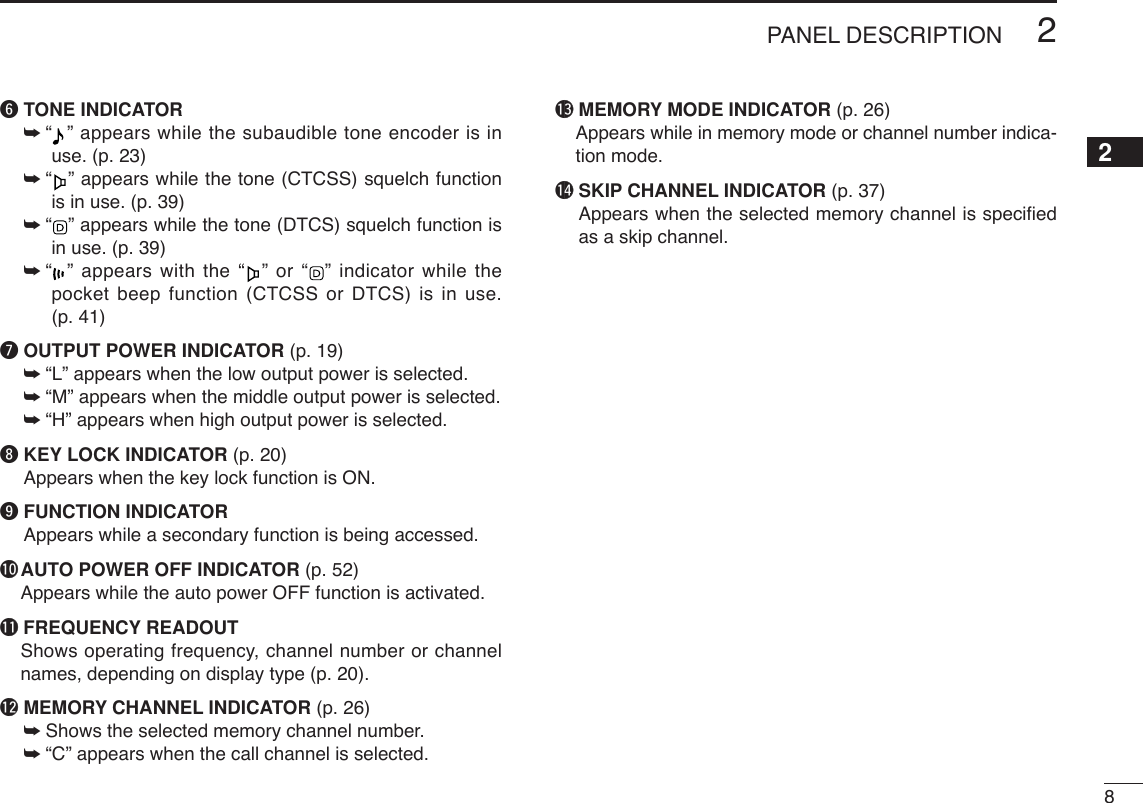
![42PANEL DESCRIPTION12345678910111213141516171819qCONTROL DIAL [VOL] (p. 19)Rotate to adjust the volume level.The assigned function for [VOL] and [YY]/[ZZ]can be ex-changed in INITIAL SET MODE(pgs. 18, 53).wPTT SWITCH [PTT]Push and hold to transmit; release to receive.eSQUELCH/MONITOR SWITCH [MONI] (p. 19)➥Push and hold to open the squelch temporarily andmonitor the operating frequency.➥While pushing and holding this key, push [YY]or [ZZ]toadjust the squelch level.The assigned function for [VOL] and [YY]/[ZZ]can beexchanged in INITIAL SET MODE(pgs. 18, 53).rUP/DOWN KEYS [YY]/[ZZ](p.18)Selects the operating frequency, set mode items, etc.The assigned function for [VOL] and [YY]/[ZZ]can be ex-changed in INITIAL SET MODE(pgs. 18, 53).tKEYPAD (pgs. 5, 6) Used to enter operating frequency, the DTMF codes, etc.yEXTERNAL DC JACK [DC 11V]➥Connect an external DC power supply through the op-tional CP-19R for external DC operation. (p. 16)➥Connect the supplied (or optional) wall charger, BC-167A/D, to charge the attached battery pack. (p. 13)uPOWER KEY [PWR] (p. 17)Push and hold for 1 sec. to turn the power ON and OFF.iFUNCTION DISPLAY (pgs. 7, 8)oEXTERNAL SPEAKER/MICROPHONE JACKS [SP/MIC]Connect an optional speaker-microphone or headset, if de-sired. The internal microphone and speaker will not func-tion when a connector is inserted.See page iv for a list of available options.!0 ANTENNA CONNECTOR (p. 1)Connects the supplied antenna.](https://usermanual.wiki/ICOM-orporated/296400/User-Guide-745010-Page-17.png)
![52PANEL DESCRIPTIONDKeypad[FUNC]Access to secondary function.[CALL]Selects the call channel. (p. 26)[MR]➥Selects a memory mode. (p. 26)➥After pushing [FUNC], enter into memory pro-gramming/editing mode. (pgs. 27–29)➥After pushing [FUNC], programs/transfersVFO/memory or call channel contents intomemory channel/VFO when pushed and heldfor 1 sec. (pgs. 27–29)[CLR]Selects VFO mode, aborts direct frequency input,or cancels scanning, etc. (pgs. 17, 35)[1•TONE]➥Input digit “1” during frequency input, memorychannel selection, etc. (pgs. 17, 26)➥After pushing [FUNC], selects the subaudibletone function. (pgs. 22, 39)[2•P.BEEP]➥Input digit “2” during frequency input, memorychannel selection, etc. (pgs. 17, 26)➥After pushing [FUNC], turns the pocket beepfunction ON and OFF. (p. 41)[3•T.SCAN]➥Input digit “3” during frequency input, memorychannel selection, etc. (pgs. 17, 26)➥After pushing [FUNC], starts tone scanning.(pgs. 24, 42)[4•DUP]➥Input digit “4” during frequency input, memorychannel selection, etc. (pgs. 17, 26)➥After pushing [FUNC], selects duplex function(–duplex, +duplex, simplex). (p. 22)[5•SCAN]➥Input digit “5” during frequency input, memorychannel selection, etc. (pgs. 17, 26)➥After pushing [FUNC], starts scanning. (p. 35)5SCAN4DUP3T.SCAN2P.BEEP1TONEDCLRCMRBCALLAFUNCA147FUNCTONEDUPPRIOB258CALLP.BEEPSCANSETC369SKIPT.SCANMRH/M/LD0CLRBANKOPTENT](https://usermanual.wiki/ICOM-orporated/296400/User-Guide-745010-Page-18.png)
![62PANEL DESCRIPTION12345678910111213141516171819[6•SKIP]➥Input digit “6” during frequency input, memorychannel selection, etc. (pgs. 17, 26)➥After pushing [FUNC], sets and cancels skipsetting for memory scan during memory mode.(p. 37)[7•PRIO]➥Input digit “7” during frequency input, memorychannel selection, etc. (pgs. 17, 26)➥After pushing [FUNC], starts priority watch.(p. 38)[8•SET]➥Input digit “8” during frequency input, memorychannel selection, etc. (pgs. 17, 26)➥After pushing [FUNC], enters into SET MODE.(p. 47)[9•H/M/L]➥Input digit “9” during frequency input, memorychannel selection, etc. (pgs. 17, 26)➥After pushing [FUNC], switches transmit powerbetween high, middle and low output power.(p. 19)When the transceiver becomes hot duringhigh or middle output power operation, thebuilt-in protection circuit activates to reducethe transmit output power to 3 W (approx.).[0•OPT]➥Input digit “0” during frequency input, memorychannel selection, etc. (pgs. 17, 26)➥After pushing [FUNC], selects an optional func-tion mode, such as pager or code squelch op-eration. (pgs. 45, 46)[#•BANK]After pushing [FUNC], enters a memory bank se-lection. (p. 30)[✱ENT•]➥Sets the frequency even if the full 6 digits offrequency have not been entered. (p. 17)➥After pushing [FUNC], switches key lock func-tion ON and OFF when pushed and held for 1sec. Lock all keys, except [PWR], [PTT],[MONI] and audio level adjustment. (p. 20)ENTBANK0OPT9H/M/L8SET7PRIO6SKIP](https://usermanual.wiki/ICOM-orporated/296400/User-Guide-745010-Page-19.png)
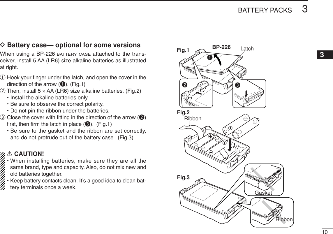
![9BATTERY PACKS3■Battery pack replacementqBefore replacing the batterypack, push and hold [PWR]for 1 sec. to turn the powerOFF.wPush the battery release button in the direction of thearrow as shown below. The battery pack is then released.DDBattery packs*1Operating periods are calculated under the following conditions;Tx : Rx : standby =1 : 1 : 8, power save function: auto setting isactivated*2Operating period depends on the alkaline cells used. Battery pack Battery release buttonDUP SCANPRIOSETH/M/LOPTSKIPBANKTONET.SCANP.BEEPABDCCALLENTMR CLRFUNCPWR9874123560PWRBattery Voltage Capacity Battery life*1packBP-226 Battery case for AA —*2(LR6)×5 alkalineBP-227 7.2 V 1700 mAh 7 hrs.](https://usermanual.wiki/ICOM-orporated/296400/User-Guide-745010-Page-22.png)
![133BATTERY PACKS■Regular chargingWhen using a BP-227 BATTERY PACKattached to the trans-ceiver, prior to using the transceiver for the first time, the bat-tery pack must be fully charged for optimum life andoperation.DDCharging note•Be sure to turn the transceiver power OFF.Otherwise the battery pack will not be charged completely or takeslonger charging time periods.•External DC power operation becomes possible when usingan optional CP-19R. The attached battery pack is alsocharged simultaneously, except during transmit. (see p. 16for more details)Even through there is no indication during regular charg-ing, the transceiver automatically stops charging the bat-tery pack when the battery pack is fully charged (BP-227’svoltage becomes approx. 7.2 V) or the continuous charg-ing time is over 15 hours.• BC-167A/D• CP-19R (Optional)to AC outletto cigarette lightersocket (12 V DC)Transceiverto [DC 11V]Turn power OFF while charging the battery pack.• Charging time period: Approx. 12–13 hours](https://usermanual.wiki/ICOM-orporated/296400/User-Guide-745010-Page-26.png)
![163BATTERY PACKS12345678910111213141516171819■External DC power operationAn optional cigarette lighter cable (CP-19R; for 12 V cigarettelighter socket) can be used for external power operation. DDOperating note•BE SURE to use optional CP-19R when connecting a regu-lated 12 V DC power supply into the [DC 11V] jack of thetransceiver.•The voltage of the external power supply must be within11.7–15.9 V DC when using CP-19R.•NEVER CONNECT OVER 16 V DC through CP19R.Use an external DC-DC converter to connect the transceiverthrough CP-19R to a 24 V DC power source.•Disconnect the power cables from the transceiver when notusing it. Otherwise, the vehicle battery will become ex-hausted.•The power save function is deactivated automatically duringexternal DC power operation.CP-19R (Optional)to cigarette lightersocket (12 V DC)Transceiverto [DC 11V]](https://usermanual.wiki/ICOM-orporated/296400/User-Guide-745010-Page-29.png)
![17BASIC OPERATION4■Power ON➥Push and hold [PWR] for 1sec. to turn power ON.■VFO mode selectionThe transceiver has 2 basic oper-ating modes: VFO mode andmemory mode.➥Push [CLR] to select VFOmode.■Setting a frequencyDVia the keypadqPush [CLR] to select VFO mode, if necessary.wTo enter the desired frequency, enter 6 digits starting fromthe 100 MHz digit.•Entering three* to five digits then pushing [✱ENT]will also setthe frequency. (*Some versions only requires two digits.)•When changing 100 kHz and below, push [#] then enter the de-sired digits.•When a digit is mistakenly input, push [CLR] to abort input.• Example 1— when entering 145.525 MHzPush• Example 2— when entering 144.800 MHzPush• Example 3— when entering 145.000 MHzPush1TONE4DUP1TONE4DUP4DUP2P.BEEP5SCAN5SCAN5SCAN8SET0OPTENTENTBANKfrom 145.525 MHzDUP SCANPRIOSETH/M/LOPTSKIPBANKTONET.SCANP.BEEPABDCCALLENTMR CLRFUNCPWR9874123560DCLRDUP SCANPRIOSETH/M/LOPTSKIPBANKTONET.SCANP.BEEPABDCCALLENTMR CLRFUNCPWR9874123560PWR](https://usermanual.wiki/ICOM-orporated/296400/User-Guide-745010-Page-30.png)
![184BASIC OPERATION12345678910111213141516171819DBy other methodsVia the [YY]/[ZZ] keys➥Push [YY]or [ZZ]several times to set the desired frequency.•Each push increases/decreases the frequency by the selectedtuning step. See next set of instructions for setting tuning stepsize.DTuning step selectionThe IC-V85 has 8 tuning steps—5, 10, 12.5, 15, 20, 25, 30 and50 kHz. The tuning step is selec-table in SET MODE.qPush [FUNC] then [SET](8) toenter SET MODE.wPush [YY]or [ZZ]several timesto select the tuning step item.eRotate [VOL] to select the desired tuning step.rPush [✱ENT](or [CLR]) to exit SET MODE.DUP SCANPRIOSETH/M/LOPTSKIPBANKTONET.SCANP.BEEPABDCCALLENTMR CLRFUNCPWR9874123560[VOL]AFUNC8SETENT✔For your information— [VOL] function assignmentThe [VOL] control can beused as a tuning dial for fre-quency tuning instead of[YY]/[ZZ]keys. However, when[VOL] functions as tuningdial, [YY]/[ZZ]keys function asvolume control.qWhile pushing and holding[YY]and [ZZ], turn powerON to enter INITIAL SETMODE. wPush [YY]or [ZZ]severaltimes to select the dial as-signment item, “tOP.”eRotate [VOL] to select the condition.rTo exit INITIAL SET MODE, push [✱ENT](or [CLR]).[VOL] is assigned as AF volume control. [VOL] is assigned as tuning dial.DUP SCANPRIOSETH/M/LOPTSKIPBANKTONET.SCANP.BEEPABDCCALLENTMR CLRFUNCPWR9874123560[VOL]PWRENT](https://usermanual.wiki/ICOM-orporated/296400/User-Guide-745010-Page-31.png)
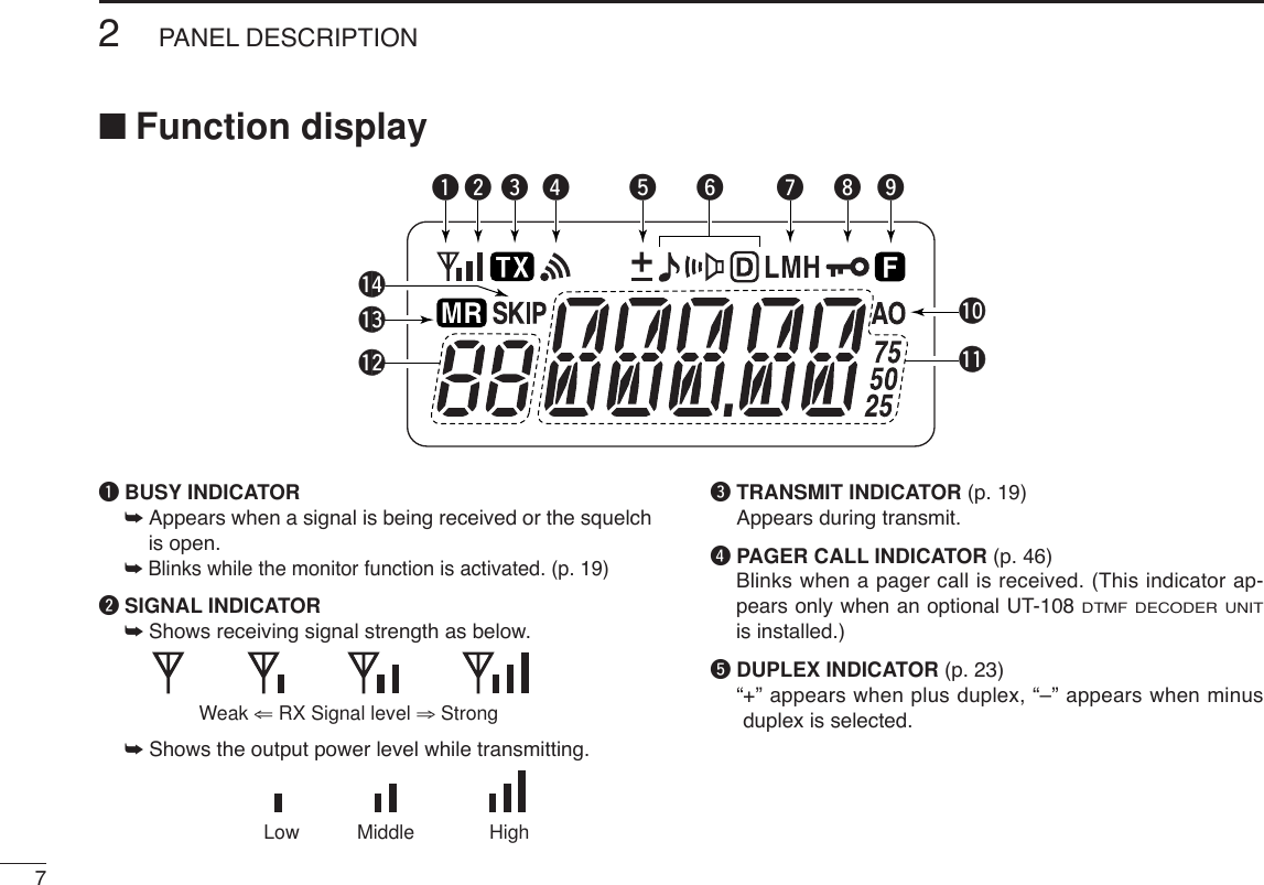
![194BASIC OPERATION■Setting audio/squelch levelDTo set the audio levelRotate [VOL] to set the desiredaudio level while receiving asignal.• When no signal is received, pushand hold [MONI] while setting theaudio level. • When [VOL] is assigned as tun-ing dial, push [YY]/[ZZ]to adjustthe audio output level. (pgs. 18,53)DTo set the squelch levelWhile pushing [MONI], push[YY]/[ZZ]to set the squelchlevel.• The squelch level “10” is tightsquelch, “1” is loose squelch and“0” is open squelch.• When [VOL] is assigned as tun-ing dial, rotate [VOL] while press-ing [MONI]. (pgs. 18, 53)■Receive and transmitqPush and hold [PWR] for 1 sec. to turn the power ON.wAdjust audio volume to the desired level.eSet the frequency.When a signal is received:• Squelch opens and audio is emitted from the speaker.• Signal indicator shows the relative signal strength level.rPush [FUNC], then [H/M/L](9) to select output power be-tween high, middle and low.•“H” appears when high power is selected.•“M” appears when middle power is selected.•“L” appears when low power is selected.tPush and hold [PTT] to transmit, then speak into the micro-phone.• “$” appears.•Do not hold the microphone too close to your mouth orspeak too loudly. This may distort the signal.yRelease [PTT] to receive. ■Monitor functionThis function is used to listen to weak signals without disturb-ing the squelch setting or to open the squelch manually evenwhen mute functions such as the tone squelch are in use.➥Push and hold [MONI] to monitor the operating frequency.The [MONI] key can be set to ‘sticky’ operation in INITIALSET MODE. See page 55 for details.DUP SCANPRIOSETH/M/LOPTSKIPBANKTONET.SCANP.BEEPABDCCALLENTMR CLRFUNCPWR9874123560MONIDUP SCANPRIOSETH/M/LOPTSKIPBANKTONET.SCANP.BEEPABDCCALLENTMR CLRFUNCPWR9874123560[VOL]](https://usermanual.wiki/ICOM-orporated/296400/User-Guide-745010-Page-32.png)
![204BASIC OPERATION12345678910111213141516171819■Display type The transceiver has 3 display types to suit your operatingstyle during memory mode operation. The display type isselected in INITIAL SET MODE(p. 53).“Frequency Indication” typeDisplays operating frequency.“Channel Number Indication” typeDisplays memory channel number. In this type only pre-programmed memory channel numbers are displayed. VFO mode cannot be selected.• When the channel indication type is selected, only the followingfunctions can be performed.- Scan function (p. 35)- Output power setting (p. 19)- DTMF memory function (p. 32)- Key lock function (see next set of instructions)- Scan pause timer setting, function key timer setting and LCDbacklight setting in SET MODE(p. 49)“Channel Name Indication” typeDisplays memory channel name you have assigned. In thisdisplay pre-programmed memory channel names are dis-played. VFO mode is selectable.• Programmed frequencies are indicated when you have not pre-programmed the channel names in the selected memory channel.• Push and hold [MONI] to display the operating frequency.■Key lock functionThe key lock function prevents accidental frequency changesand function activation.Push [FUNC] then push and hold[](✱ENT) for 1 sec. to toggle thefunction ON and OFF.•“ ” appears while the lock function is ac-tivated.•[PWR], [PTT], [VOL] and [MONI] can beoperated regardless of this setting.USINGINITIAL SET MODEDUP SCANPRIOSETH/M/LOPTSKIPBANKTONET.SCANP.BEEPABDCCALLENTMR CLRFUNCPWR9874123560AFUNCENT](https://usermanual.wiki/ICOM-orporated/296400/User-Guide-745010-Page-33.png)
![214BASIC OPERATIONDDWeather channel selectionqPush [MR] several times to select weather channel group. wPush [YY]or [ZZ]several times to select the desiredweather channel. ePush [MR] to select memory mode, or push [CLR] to se-lect VFO mode.DDWeather alert functionAn NOAA broadcast station transmits weather alert tone be-fore important weather announcements. When the weatheralert function is turned ON, the selected weather channel ismonitored each 5 sec. for the announcement. When the alertsignal is detected, the “ALt” and the WX channel are dis-played alternately and sounds a beep tone until the trans-ceiver controls are manipulated. The previously selectedweather channel is checked periodically during standby orwhile scanning.qSelect the desired weather channel.wTurn the weather alert function ON in SET MODE.➥Push [FUNC] and [SET](8) to enter SET MODE.➥Push [YY]or [ZZ]to select the weather alert item, thenrotate [VOL] to set ON.➥push [✱ENT](or [CLR]) to exit SET MODE.eSelect the desired stand-by condition.•Select VFO, memory or call channel.•Scan or priority watch operation can also be selected.rWhen the alert is detected, a beep sounds and the follow-ing indication will be displayed.• Weather alert function OFF➥ Turn the weather alert function OFF in SET MODE.•Repeat above procedure described at step wNOTE: While receiving a signal (on a frequency other thanthe weather alert ON frequency), the receiving signal oraudio will be interrupted momentarily every 5 sec. (approx.)in case the alert function is turned ON. This is caused bythe WX alert function. To eliminate the interruptions, set theweather alert item OFF in SET MODE.Shows above indications alternately.USINGSET MODEWeather channel group indication■Weather channel operation (USA version only)](https://usermanual.wiki/ICOM-orporated/296400/User-Guide-745010-Page-34.png)
![225REPEATER OPERATION12345678910111213141516171819■GeneralWhen using a repeater, the transmit frequency is shifted fromthe receive frequency by the offset frequency. It is convenientto program repeater information into memory channels.qSet the receive frequency (repeater output frequency).wPush [FUNC] and [DUP](4)several times to select “–” or “+.”•“–” indicates the transmit frequency is shifted down; “+” indicatesthe transmit frequency is shifted up.• Blinking “–” or “+” indicates the reversed duplex mode is selectedin SET MODE(p. 48).ePush [FUNC] and [TONE](1) several times to activate thesubaudible tone encoder, if required.•“ ” appears.•Select the desired subaudible tone frequency, if necessary. (p. 23)rPush and hold [PTT] to transmit.•The displayed frequency automatically changes to the transmitfrequency (repeater input frequency).•If “OFF” appears, check the offset frequency (see next page fordetails) and direction.tRelease [PTT] to receive.yPush and hold [MONI] to check whether the other station’stransmit signal can be directly received.■Reversed duplex modeWhen the reversed duplex mode is selected, the receive fre-quency shifts. (Transmit frequency shifts in normal duplex mode.)Each receive and transmit frequency is shown in the tablebelow with the following conditions;Input frequency : 145.30 MHzDirection : – (negative)Offset frequency : 0.6 MHzqPush [FUNC], then push [SET](8) to enter SET MODE.wPush [YY]or [ZZ]several times until “REV” appears.eRotate [VOL] to turn the reversed duplex mode ON orOFF.rPush [✱ENT](or [CLR])to exit SET MODE.USINGSET MODEReversed OFF ON Rx freq. 145.30 MHz 144.70 MHzTx freq. 144.70 MHz 145.30 MHz](https://usermanual.wiki/ICOM-orporated/296400/User-Guide-745010-Page-35.png)
![235REPEATER OPERATION■Offset frequencyWhen communicating through a repeater, the transmit fre-quency is shifted from the receive frequency by an amountdetermined by the offset frequency.qPush [FUNC], then push [SET](8) to enter SET MODE.wPush [YY]or [ZZ]several times until “±” and offset frequencyappear.eRotate [VOL] to select the desired offset frequency.•Selectable steps are the same as the pre-set tuning steps.•The unit of the displayed offset frequency is “MHz.”rPush [✱ENT](or [CLR]) to set the offset frequency and exitSET MODE.■Subaudible tonesSome repeaters require subaudible tones to be accessed.Subaudible tones are added to your normal signal and mustbe set in advance.qPush [FUNC], then push [SET](8) to enter SET MODE.wPush [YY]or [ZZ]several times until “rt” appears.eRotate [VOL] to select the desired subaudible tone.rPush [✱ENT](or [CLR]) to set the selected tone and exitSET MODE.• Available subaudible tone frequencies (unit: Hz)67.069.371.974.477.085.488.591.594.897.4100.0103.579.782.5107.2110.9114.8118.8123.0127.3131.8136.5141.3146.2151.4156.7159.8162.2165.5167.9171.3173.8177.3179.9183.5186.2189.9192.8196.6199.5203.5206.5210.7218.1225.7229.1233.6241.8250.3254.1USINGSET MODEUSINGSET MODE](https://usermanual.wiki/ICOM-orporated/296400/User-Guide-745010-Page-36.png)
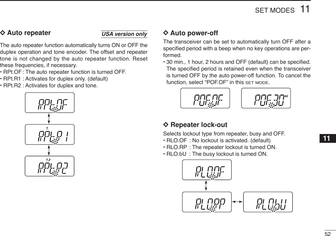
![245REPEATER OPERATION12345678910111213141516171819DDTone informationSome repeaters require different tone system to be accessed. DTMF TONESWhile pushing [PTT], push the desired DTMF keys ([0]–[9],[A], [B], [C], [D], [#] and [✱]) to transmit DTMF tones.•[✱]transmits tone “E,” [#] transmits tone “F.”•The transceiver has 16 DTMF memory channels (p. 32).1750 Hz TONEWhile pushing [PTT], push [YY]or [ZZ]to transmit a 1750 Hztone signal.✔ConvenientTone scan function: When you don’t know the subaudibletone used for a repeater, the tone scan is convenient for de-tecting the tone frequency.Push [FUNC], then push [T.SCAN](3) to start the tone scan.• Push [CLR] to cancel the scan.• When the required tone frequency is detected, the scan pauses.■Repeater lockoutThis function helps prevent interference to other stations byinhibiting your transmission when a signal is received. Thetransceiver has two inhibiting conditions, repeater and busy. qWhile pushing and holding [YY]and [ZZ], turn the power ONto enter INITIAL SET MODE.wPush [YY]or [ZZ]several times until “RLO” appears.eRotate [VOL] to select the repeater lockout function to“RP,” “bU” or OFF.•“RP”: Transmit is inhibited when a signal with un-matched sub-audible tone is received.•“bU”: Transmit is inhibited when a signal is received.rPush [✱ENT](or [CLR]) to exit INITIAL SET MODE.USINGINITIAL SET MODE](https://usermanual.wiki/ICOM-orporated/296400/User-Guide-745010-Page-37.png)
![255REPEATER OPERATIONThe USA version automatically activates the repeater settings(duplex ON/OFF, duplex direction, tone encoder ON/OFF)when the operating frequency falls within or outside of thegeneral repeater output frequency range. The offset and re-peater tone frequencies are not changed by the auto repeaterfunction. Reset these frequencies, if necessary.qWhile pushing and holding [YY]and [ZZ], turn the power ONto enter INITIAL SET MODE.wPush [YY]or [ZZ]several times until “RPt” appears.eRotate [VOL] to select the desired condition.•“OF”— the auto repeater function is turned OFF;•“R1”— the auto repeater function activates duplex only;•“R2”— the auto repeater function activates duplex and tone.rPush [✱ENT](or [CLR]) to exit INITIAL SET MODE.• Frequency range and offset directionFrequency range Duplex direction145.200–145.495 MHz “–” appears146.610–146.995 MHz147.000–147.395 MHz “+” appears■Auto repeater function (USA version only)USINGINITIAL SET MODE](https://usermanual.wiki/ICOM-orporated/296400/User-Guide-745010-Page-38.png)
![266MEMORY/CALL OPERATION12345678910111213141516171819■Selecting a memory channelqPush [MR] to select memory mode.•“X” appears.wEnter 2 digits to select the desired memory channel (orpush the [YY]/[ZZ]keys).•The memory channels 0–9 are proceeded by a “0.”• When [VOL] is assigned as tuning dial, rotate [VOL] to selectthe memory channel. (pgs. 18, 53)■Selecting the call channel➥Push [CALL] to select the call channel.•“C” is displayed instead of the memory channel number.•Push [CLR] or [MR] to select VFO or memory mode, respec-tively.PushCALLB“C” appearsPush(Selection example: Memory channel 14)DUPTONE41PushMRCThe transceiver has 107 memory channels including 6 scanedge memory channels (3 pairs), and 1 call channel. Eachof these channels can be individually programmed with op-erating frequency (pgs. 17, 18), duplex direction (p. 22) andoffset (p. 23), subaudible tone encoder or tone squelch andits tone frequency (pgs. 23, 40) and skip information* (p. 37). *except for scan edge memory channels.In addition, a total of 10 memory banks, A to J, are availablefor usage by group, etc.■General description](https://usermanual.wiki/ICOM-orporated/296400/User-Guide-745010-Page-39.png)
![276MEMORY/CALL OPERATIONqPush [CLR] to select VFO mode, if necessary.wSet the desired frequency.eSet other information, such as tone, duplex, as desired.rPush [FUNC], then [MR] momentarily.•“X” and memory channel number blink.tPush [YY]or [ZZ]to select the desired memory channel.• When programming the call channel, select “C.”• When [VOL] is assigned as tuning dial, rotate [VOL] to selectthe memory channel. (pgs. 18, 53)yPush [FUNC], then push and hold [MR] for 1 sec., when 3beeps will sound to program the information into the se-lected memory channel and return to VFO. •After 3 beeps are emitted, continue to hold [MR] to increment thedisplayed memory channel number.DUP SCANPRIOSETH/M/LOPTSKIPBANKTONET.SCANP.BEEPABDCCALLENTMR CLRFUNCPWR9874123560AFUNCCMRPWRA147FUNCTONEDUPPRIOB258CALLP.BEEPSCANSETC369SKIPT.SCANMRH/M/LD0CLRBANKOPTENTDUP SCANPRIOSETH/M/LOPTSKIPBANKTONET.SCANP.BEEPABDCCALLENTMR CLRFUNCPWR9874123560AFUNCCMR■Programming the memory/call channels](https://usermanual.wiki/ICOM-orporated/296400/User-Guide-745010-Page-40.png)
![286MEMORY/CALL OPERATION12345678910111213141516171819■Channel name programming qSelect a “Channel Name Indication” type in INITIAL SETMODE(p. 53).wPush [MR] to select memorymode, if necessary.ePush [FUNC], then push[SET](8) to enter to the channelname programming mode.• The character to be edited blinks.rRotate [VOL] to select a char-acter.tPush [YY]to move the cursor toright, [ZZ]to move the cursor toleft.• Up to 5 characters can be used for channel name.• Usable characters are A–Z, 0–9, “space,” +, –, =, ✱, /, [, ] and :.yPush [✱ENT](or [CLR]) to set the name and exit the chan-nel name programming mode.■Memory transfersThis function transfers a memory channel’s contents to VFO(or another memory/call channel). This is useful when search-ing for signals around a memory channel frequency and forrecalling the offset frequency, subaudible tone frequency etc.DMemory/call ➾VFOqSelect the memory (call) chan-nel to be transferred:➥Push [MR] (or [CALL]) to se-lect memory (call channel)mode.➥Push [YY]or [ZZ]to select thememory channel.• When [VOL] is assigned astuning dial, rotate [VOL] to se-lect the memory channel. (pgs.18, 53)wPush [FUNC], then push andhold [MR] for 1 sec. to transferthe selected memory contentsto the VFO.•VFO mode is selected automatically.DUP SCANPRIOSETH/M/LOPTSKIPBANKTONET.SCANP.BEEPABDCCALLENTMR CLRFUNCPWR9874123560[VOL]AFUNCBCALLCMRDUP SCANPRIOSETH/M/LOPTSKIPBANKTONET.SCANP.BEEPABDCCALLENTMR CLRFUNCPWR9874123560[VOL]AFUNC8SETCMRENT](https://usermanual.wiki/ICOM-orporated/296400/User-Guide-745010-Page-41.png)
![296MEMORY/CALL OPERATIONDMemory/call ➾memory/callqSelect the memory (call) chan-nel to be transferred:➥Push [MR] (or [CALL]) to se-lect the memory (call chan-nel) mode.➥Push [YY]or [ZZ]to select thememory channel.• When [VOL] is assigned astuning dial, rotate [VOL] to se-lect the memory channel. (pgs.18, 53)wPush [FUNC], then push [MR]momentarily.•“--” and “X” blink.ePush [YY]or [ZZ]to select the target memory.• When [VOL] is assigned as tuning dial, rotate [VOL] to selectthe target channel. (pgs. 18, 53)rPush [FUNC], then push and hold [MR] for 1 sec.•Memory mode is selected and the contents are transferred to thetarget memory.DClearing a memoryqPush [CLR] to select VFO mode, if necessary.wPush [FUNC], then push [MR] to enter the memory trans-fer mode.•“X” and a memory channelnumber blink.ePush [YY]or [ZZ]to select thememory channel to be cleared.• When [VOL] is assigned as tun-ing dial, rotate [VOL] to select thememory channel. (pgs. 18, 53)•The call channel cannot becleared.rPerform the following operationwithin 1 sec, otherwise thetransceiver returns to the mem-ory mode without clearing thememory.- Push [FUNC], then push [MR] momentarily.- Push [FUNC], then push and hold [MR] for 1 sec.•The contents of the selected memory are cleared.tPush [CLR] to return to regular operation.DUP SCANPRIOSETH/M/LOPTSKIPBANKTONET.SCANP.BEEPABDCCALLENTMR CLRFUNCPWR9874123560[VOL]AFUNCBCALLCMRDUP SCANPRIOSETH/M/LOPTSKIPBANKTONET.SCANP.BEEPABDCCALLENTMR CLRFUNCPWR9874123560AFUNCCMR](https://usermanual.wiki/ICOM-orporated/296400/User-Guide-745010-Page-42.png)
![306MEMORY/CALL OPERATION12345678910111213141516171819■Memory bank selectionThe IC-V85 has a total of 10 banks (A to J). Each memorychannel, 0 to 99, may be assigned to one of the banks foreasy memory management. qPush [MR] to select memory mode.wPush [FUNC] and [BANK](#) toenter memory bank selection.•Bank indicator blinks.eRotate [VOL] to select the de-sired bank, A to J.•Banks that have no programmedcontents are skipped.rPush [✱ENT](or [CLR]) to selectthe bank.•Indicator stops blinking.tPush [YY]or [ZZ]to select the channel in the bank.•No channel numbers are displayed for memory bank operation.yTo return to regular memory condition, push [FUNC] and[BANK](#) to enter memory bank mode, then push [✱ENT](or [CLR]).■Memory bank settingqPush [MR] to select memory mode, then select the desiredmemory channel via [YY]or [ZZ].wPush [FUNC] and [SET](8) toenter SET MODE.ePush [YY]or [ZZ]several timesuntil “bAk” appears.rRotate [VOL] to select the de-sired bank.tPush [✱ENT](or [CLR]) to assign the channel to the bankand return to regular memory condition.yRepeat steps qto tto assign another memory channelto the same or another bank.NOTE: Display type setting (pgs. 20, 53) in INITIAL SETMODEmust be selected “FR,” otherwise the memory bankoperation cannot be performed.DUP SCANPRIOSETH/M/LOPTSKIPBANKTONET.SCANP.BEEPABDCCALLENTMR CLRFUNCPWR9874123560[VOL]AFUNC8SETENTPushMRCDUP SCANPRIOSETH/M/LOPTSKIPBANKTONET.SCANP.BEEPABDCCALLENTMR CLRFUNCPWR9874123560[VOL]AFUNCBANKENTPushMRC](https://usermanual.wiki/ICOM-orporated/296400/User-Guide-745010-Page-43.png)
![316MEMORY/CALL OPERATION■Transferring bank contentsContents of programmed memory banks can be cleared ortransferred to another bank.INFORMATION: Even if the memory bank contents arecleared, the memory channel contents still remain pro-grammed.qSelect the desired bank contents to be transferred or erased.➥Push [MR] to select memory mode.➥Push [FUNC] and [BANK](#),then rotate [VOL] to select thedesired memory bank.•Bank indicator blinks.➥Push [✱ENT](or [CLR]) to se-lect the bank then push [YY]and [ZZ]to select the desiredcontents.•Bank indicator stops blinking.wPush [FUNC] and [SET](8) toenter SET MODE.ePush [YY]or [ZZ]several timesuntil “bAk” appears.•Bank indicator appears.rRotate [VOL] to select the de-sired bank to receive the trans-ferred information or erase thebank contents.•Select “– –” indication when erasingthe contents from the bank.tPush [✱ENT](or [CLR]) to transfer or erase, and return toregular memory mode.yRepeat steps qto tfor transferring or erasing an an-other bank’s contents.DUP SCANPRIOSETH/M/LOPTSKIPBANKTONET.SCANP.BEEPABDCCALLENTMR CLRFUNCPWR9874123560[VOL]AFUNC8SETENTDUP SCANPRIOSETH/M/LOPTSKIPBANKTONET.SCANP.BEEPABDCCALLENTMR CLRFUNCPWR9874123560[VOL]AFUNCBANKENT](https://usermanual.wiki/ICOM-orporated/296400/User-Guide-745010-Page-44.png)
![327DTMF MEMORY12345678910111213141516171819■Programming a DTMF code sequenceThe transceiver has 16 DTMF memory channels (d0 to dF)for storage of often-used DTMF code sequence of up to 24digits. DTMF memories are used to store phone numbers orcontrol codes.qPush [FUNC], then push [OPT](0)to enter OPTION SET MODE.•Rotate [VOL] to select “dtm.OF,” if necessary.wPush and hold [OPT](0)for 1 sec. to select the DTMF mem-ory.•One of “d0” to “dF” appears.eRotate [VOL] to select the desired DTMF memory.rPush and hold [OPT](0) for 1 sec. to enter the DTMF pro-gramming mode.•“_____” appears.•Programmed memories can be cleared in this way.tEnter the desired DTMF code sequence by pushing thedigit keys, [A], [B], [C], [D], [#] and [✱], in the desiredsequence.•Amaximum of 24 digits can be input.•[✱]enters tone “E”, [#] enters tone “F.”•If a digit is mistakenly input, push [MONI] or [PTT] momentarilythen repeat from step q.yPush [MONI] or [PTT] to save the digits and exit the DTMFprogramming mode.•Programmed DTMF code sequence sounds when [MONI] ispushed.•Or after 24th digit is input, the transceiver automatically savesthe digits and returns to step w.DUP SCANPRIOSETH/M/LOPTSKIPBANKTONET.SCANP.BEEPABDCCALLENTMR CLRFUNCPWR9874123560A147FUNCTONEDUPPRIOB258CALLP.BEEPSCANSETC369SKIPT.SCANMRH/M/LD0CLRBANKOPTENTMONIPushOPT0for 1 sec.PushOPT0for 1 sec.PushFUNCAOPT0](https://usermanual.wiki/ICOM-orporated/296400/User-Guide-745010-Page-45.png)
![337DTMF MEMORY• DTMF memory indication■Transmitting a DTMF codesequenceDUsing a DTMF memory channelqPush [FUNC], then push [OPT](0)to enter OPTION SET MODE.•Rotate [VOL] to select “dtm.OF,” if necessary.wPush and hold [OPT](0)for 1 sec. to select the DTMF mem-ory.eRotate [VOL] to select the desired memory.rPush [MONI] or [PTT] to exit the DTMF memory mode.•Selected DTMF code sequence sounds when [MONI] is pushed.tWhile pushing [PTT], push [MONI] to transmit the selectedDTMF memory.•After the DTMF code sequence is transmitted, the transceiver re-turns to receive automatically.PushOPT0for 1 sec.PushFUNCAOPT0The DTMF memory consists of 5 pages that are 1st to 5th,6th to 10th, 11th to 15th, 16th to 20th and 21st to 24th dig-its. AppearsBlinksAppearsAppears• 1st page indication• 4th page indication• 5th page indication• 2nd page indication• 3rd page indication](https://usermanual.wiki/ICOM-orporated/296400/User-Guide-745010-Page-46.png)
![347DTMF MEMORY12345678910111213141516171819DManual DTMF code transmissionWhile pushing [PTT], push digit keys, [A], [B], [C], [D], [#]and [✱]to transmit a DTMF code sequence manually.•[✱]transmits tone “E”, [#] transmits tone “F.”■DTMF transmission rateWhen slow DTMF transmission rates are required with DTMFmemory transmission (as for some repeaters), the trans-ceiver’s rate of DTMF transmission can be adjusted.qWhile pushing and holding [YY]and [ZZ], turn the power ON toenter INITIAL SET MODE.wPush [YY]or [ZZ]several timesuntil “dtd” appears.eRotate [VOL] to select the de-sired DTMF transmission rate.•Four rates are available: “1” (100msec. intervals) is the fastest; “5”(500 msec. intervals) is the slow-est.rPush [✱ENT](or [CLR]) to exit INITIAL SET MODE.DUP SCANPRIOSETH/M/LOPTSKIPBANKTONET.SCANP.BEEPABDCCALLENTMR CLRFUNCPWR9874123560[VOL]PWRENTUSINGINITIAL SET MODEDUP SCANPRIOSETH/M/LOPTSKIPBANKTONET.SCANP.BEEPABDCCALLENTMR CLRFUNCPWR9874123560A147FUNCTONEDUPPRIOB258CALLP.BEEPSCANSETC369SKIPT.SCANMRH/M/LD0CLRBANKOPTENT](https://usermanual.wiki/ICOM-orporated/296400/User-Guide-745010-Page-47.png)
![35SCAN OPERATION8■Programmed scanProgrammed scan repeatedly scans between two user pro-grammed frequencies (memory channels “1A–3A” and“1b–3b”) or scans between upper and lower band edges. Thisscan is useful for checking for signals within a specific fre-quency range such as repeater output frequencies, etc.Scans between lower (start) and high (stop) frequency.qPush [CLR] to select VFO mode, if necessary.wPush [FUNC] and [SCAN](5) to start a scan.ePush [FUNC] and [SET](8) several times to select the de-sired scan edge, “P1,” “P2,” “P3” or “AL.”• “AL” for full scan, “P1”, “P2” and “P3” for programmed scan be-tween the programmed scan edge channels as “1A”–“1b,”“2A”–“2b” and “3A”–“3b.”•To change the scan direction, push [YY]or [ZZ].• When [VOL] is assigned as tuning dial, rotate [VOL] to changethe scan direction. (pgs. 18, 53)rPush [CLR] to stop the scan.PushSET8FUNCAPushFUNCASCAN5PROGRAMMED SCANMEMORY (SKIP) SCANPRIORITY WATCHBandedge BandedgeStart1A2A3AEnd1b2b3bScan edgesScanJumpSKIP SKIPSKIPMch 1Mch 0Mch 2 Mch 3Mch 3Mch 4 Mch 5Mch 10Mch 99Mch 9 Mch 8 Mch 7Mch 6Mch 1Mch 2Mch 3Mch 4Mch 5Mch 99Mch 6VFO frequency145.20 MHzVFO frequency145.20 MHz5 sec. 50 msec.5 sec. 50 msec.Priority channelPriority channelsMemoryscanPriority memory channel watchPriority memory channel scanProgrammed scan P1 scans between 1A and 1b, P2 scans be-tween 2A and 2b, and P3 scans between 3A and 3b frequencies.■Scan types](https://usermanual.wiki/ICOM-orporated/296400/User-Guide-745010-Page-48.png)
![368SCAN OPERATION12345678910111213141516171819NOTE: Scan edges, 1A–3A/1b–3b, must be programmedin advance. Program them in the same manner as regularmemory channels. (p. 27)If identical frequencies are programmed into the scanedges, programmed scan will not proceed.■Memory scanMemory scan repeatedly scans all programmed memorychannels, except those set as skip channels.qPush [MR] to select memory mode, if necessary.•“X” appears.•See below to select bank scan.wPush [FUNC] and [SCAN](5) to start the scan.•To change the scan direction, push [YY]or [ZZ].• When [VOL] is assigned as tuning dial, rotate [VOL] to changethe scan direction. (pgs. 18, 53)ePush [CLR] to stop the scan.• Bank scan —Select the desired bank in step qabove.qPush [FUNC] and [BANK](#) to select memory bank mode.wRotate [VOL] to select the desired bank, A to J.ePush [✱ENT](or [CLR]) to select the bank.PushFUNCASCAN5DUP SCANPRIOSETH/M/LOPTSKIPBANKTONET.SCANP.BEEPABDCCALLENTMR CLRFUNCPWR9874123560PWRA147FUNCTONEDUPPRIOB258CALLP.BEEPSCANSETC369SKIPT.SCANMRH/M/LD0CLRBANKOPTENT](https://usermanual.wiki/ICOM-orporated/296400/User-Guide-745010-Page-49.png)
![378SCAN OPERATION■Skip channelsIn order to speed up the scan rate, you can select memorychannels you don’t wish to scan as skip channels.qPush [MR] to select memory mode, if necessary.•“X” appears.wSelect a memory channel to set as a skip channel.ePush [FUNC] and [SKIP](6) to toggle the skip setting ONand OFF.•“SKIP” appears when the channel is set as a skip channel.■Scan resume conditionWhen a signal is received during scanning, the scan resumecondition determines what action the transceiver takes. Thetransceiver has 2 scan resume conditions available asillustrated below. UseSET MODEto select the one which bestsuits your needs.qPush [FUNC], then push [SET](8) to enter SET MODE.wPush [YY]or [ZZ]several times until “SCP” or “SCt” ap-pears.eRotate [VOL] to select the desired scan resume condition.•Pause scan:When receiving a signal, scan pauseson the signal until it disappears. Re-sumes 2 sec. after the signal disap-pears. •Timer scan:When receiving a signal, scan pauseson the signal for 5 sec., 10 sec. or 15sec., then resumes.rPush [✱ENT](or [CLR]) to set andexit SET MODE.Timer scanPause scanUSINGSET MODEPushSKIPFUNCA6“SKIP” appears](https://usermanual.wiki/ICOM-orporated/296400/User-Guide-745010-Page-50.png)
![388SCAN OPERATION12345678910111213141516171819■Priority watchPriority watch checks for signals on “priority channels” whileoperating on a VFO frequency.DMemory or call channel watchWhile operating on a VFO frequency, memory or call channelwatch monitors for signals in the selected memory or callchannel every 5 sec.qSelect the desired memory channel or the call channel.wPush [CLR] to select VFO mode.ePush [FUNC], then push [PRIO](7) to start watching.•VFO is displayed, then the decimal point “.”, on the frequencyreadout blinks.•The priority channel is monitored every 5 sec. • When the signal is detected on the priority channel, the watchingis suspended according to the setting of the scan resume condi-tion.rPush [CLR] to stop watching.DMemory scan watchWhile operating on a VFO frequency, memory scan watchmonitors for signals in each memory channel in sequence,every 5 sec.qPush [MR] to select memory mode, if necessary.•“X” appears.wPush [FUNC], then push [SCAN](5) to start the memoryscan.ePush [FUNC], then push [PRIO](7) to start the watching.•VFO is displayed, then the decimal point “.”, on the frequencyreadout blinks.• When the signal is detected on the priority channel, the watchingis suspended according to the setting of the scan resume condi-tion.rPush [CLR] to stop the watching.SKIPMch 1Mch 2Mch 3Mch 4Mch 5Mch 99Mch 6Priority channelMemoryscan5 sec.50 msec.VFO frequency5 sec. 50 msec.VFO frequency Memory channel](https://usermanual.wiki/ICOM-orporated/296400/User-Guide-745010-Page-51.png)
![39SUBAUDIBLE TONES9■Tone squelchDOperationThe tone squelch opens only when receiving a signal con-taining a matching subaudible tone. You can wait for callsfrom group members using the same tone and not hear othersignals.qSet the operating frequency.• Set the volume and squelch to the desired level as the normal op-eration.wSet the desired subaudible tone in SET MODE.• See page 40 for programming.ePush [FUNC], then push [TONE](1).•Repeat several times until “ ” appears when selecting CTCSS,or “ ” appears when selecting DTCS.rWhen the received signal includes a matching tone,squelch opens and the signal can be heard.• When the received signal’s tone does not match, tone squelchdoes not open, however, the S-indicator shows signal strength.• To open the squelch manually, push and hold [MONI].tTransmit in the normal way.yTo cancel the tone squelch, push [FUNC] and [TONE](1).•Repeat several times until “ ” or “ ” disappears.NOTE: The transceiver has 50 tone frequencies and con-sequently their spacing is narrow compared to units having38 tones. Therefore, some tone frequencies may receiveinterference from adjacent tone frequencies.To prevent interference from adjacent tone frequencies,using the frequencies as in the following table, is recom-mended.• Recommended CTCSS frequencies (Unit: Hz)• Recommended DTCS codes02302502603103204304705105406507107207307411411511612513113213414315215515616216517217420522322624324424525126126326527130631131533134334635136436537141141241342343143244546446546650350651653254656560661262462763163265466266470371272373173273474375467.069.371.974.477.079.782.585.488.591.594.897.4100.0103.5107.2110.9114.8118.8123.0127.3131.8136.5141.3146.2151.4156.7162.2167.9173.8179.9186.2192.8203.5210.7218.1225.7233.6241.8250.3DPushTONE1FUNCACTCSS DTCSD](https://usermanual.wiki/ICOM-orporated/296400/User-Guide-745010-Page-52.png)
![409SUB AUDIBLE TONES12345678910111213141516171819Separate tone frequencies can be select for tone squelch op-eration rather than repeater operation (the same range oftones is available— see right below). Like the repeater tones,these are set in SET MODE.qSelect VFO or memory channel.wPush [FUNC], then push [SET](8) to enter SET MODE.ePush [YY]or [ZZ]several times until “Ct” appears when se-lecting CTCSS, or “dt” appears when selecting DTCS.•“ ” blinks when selecting CTCSS, or “ ” blinks when selectingDTCS.rRotate [VOL] to select the desired subaudible tone.tPush [✱ENT](or [CLR]) to program the selected tone andexit SET MODE.•The recommended CTCSS frequencies or DTCS codes areshown at previous page.When SET MODEis selected from memory mode.The tone squelch frequency is not stored in the selectedmemory channel unless you follow steps yand u. yPush [FUNC], then push and hold [MR] for 1 sec. to trans-fer the contents to VFO.•3 beeps are emitted. •VFO mode is selected automatically. uPush [FUNC], then push and hold [MR] for 1 sec. •3 beeps are emitted.•Available CTCSS tone frequency (unit: Hz)•Available DTCS codes02302502603103203604304705111612212513113213414314515222522624324424524625125225537141141241342343143244544651652352653254656560661262405305406507107207307411411515515616216517217420521222332533133234334635135636436545245445546246446546650350662763163265466266470371272373173273474375426126326526627127430631131567.069.371.974.477.079.782.585.488.591.594.897.4100.0103.5107.2110.9114.8118.8123.0127.3131.8136.5141.3146.2151.4156.7159.8162.2165.5167.9171.3173.8177.3179.9183.5186.2189.9192.8196.6199.5203.5206.5210.7218.1225.7229.1233.6241.8250.3254.1CTCSS DTCSDDSetting subaudible tones for tone squelch operation](https://usermanual.wiki/ICOM-orporated/296400/User-Guide-745010-Page-53.png)
![419SUBAUDIBLE TONES■Pocket beep operationThis function listens for subaudible tones and can be used asa “common pager” to inform you that someone has calledwhen you were away from the transceiver.DWaiting for a call from a specific stationqSet the operating frequency.wSet the desired CTCSS tone frequency or DTCS code inSET MODE.• See p. 40 for programming details.ePush [FUNC], then push [TONE](1).•Repeat several times until “ ” appears when CTCSS, or “ ” ap-pears when DTCS is selected.rPush [FUNC], then push [P.BEEP](2) to activate the pocketbeep function.•“” appears.tWhen a signal with the matching tone is received, thetransceiver emits beep tones and blinks “ .”• Beep tones sound for 30 sec. and “ ” blinks. To stop the beepsmanually, push any key. “ ” continues blinking until step yisoperated.yPush [PTT] to answer.• “ ” disappears and cancels the pocket beep function automati-cally. CTCSS DTCSPushP.BEEP2FUNCACTCSS DTCSPushTONE1FUNCACTCSS DTCSD](https://usermanual.wiki/ICOM-orporated/296400/User-Guide-745010-Page-54.png)
![429SUB AUDIBLE TONES12345678910111213141516171819■Tone scanBy monitoring a signal on a repeater, or using pocket beep or tonesquelch function, you can determine the tone frequency necessary toaccess a repeater or open the squelch.qSet the frequency to be checked for a tone frequency or code.wPush [FUNC], then push [TONE](1).•Repeat several times to select the type of tone to be scanned. (One of “ ,”“” or “ ” appears)•Tone scan may be used even if the tone condition or type is not selected.ePush [FUNC], then push [T.SCAN](3) to start the tone scan.• To change the scanning direction, push [YY]or [ZZ]. PushT.SCAN3FUNCAPushTONE1FUNCADrWhen the CTCSS tone frequency or DTCS codeis matched, the squelch opens and the tone fre-quency or code is temporarily programmed intothe selected mode such as memory or call chan-nel.•The tone scan pauses when a CTCSS tone fre-quency or 3-digit DTCS code is detected.•The decoded CTCSS tone frequency or 3-digit DTCScode is used for the tone encoder or tone encoder/de-coder depending on the selected tone condition ortype in step w.-No indication : Cannot be used for operation.-“ ” : CTCSS tone encoder-“ ” : CTCSS tone encoder/decoder-“ ” : DTCS tone encoder/decodertPush [CLR] to stop the scan.D](https://usermanual.wiki/ICOM-orporated/296400/User-Guide-745010-Page-55.png)
![43PAGER/CODE SQUELCH10■Pager functionThis function uses DTMF codes for paging and can be usedas a “message pager” to confirm you of a caller’s identificationeven when you leave the transceiver temporarily unattended.■Code programmingDDBefore programmingThe pager and code squelch functions require ID codes and agroup code. These codes are 3-digit DTMF codes and mustbe written into the code channels before operation.qDecide the ID code of each transceiver and a group codefor your group.wDecide whether you want to return to normal operation orcode squelch operation after a connection is made.eProgram the ID code, group code and transmit codes(other station’s codes) as below.DDCode channel assignment*Channel CP automatically memorizes an ID code when receiving apager call. The contents in channel CP cannot be changed manually.Pager selective code (push [PTT])Beep BeepBeep Answer back (manual)Beep BeepBeep Set both transceivers to eithercode squelch or non-coded operationCommunicationID OR CODE CHANNEL “RECEIVE ACCEPT” OR GROUP CODE NUMBER “RECEIVE INHIBIT”Your ID codeOther parties’ID codeGroup codeMemory space*01–6One of 1–6P“Receive accept” only“Receive inhibit” should be programmed in each channel.“Receive accept” must be programmed in one channel.“Receive inhibit” only.Requires Optional UT-108Optional UT-108 is required when using the pager/code squelch functions.](https://usermanual.wiki/ICOM-orporated/296400/User-Guide-745010-Page-56.png)
![4410PAGER/CODE SQUELCH12345678910111213141516171819DDCode programmingYour ID code MUST be programmed into code channel C0.Up to 6 transmit codes (codes that you transmit) are pro-grammable into code channels, C1 to C6, if required.qPush [FUNC], then push [OPT](0) to enter OPTION SETMODE.•Rotate [VOL] to select “dtm.PG” or “dtm.CS,” if “dtm.OF” ap-pears.wPush and hold [OPT](0) for 1sec. to enter the code selectionmode.•One of either “CP” or “C0” to “C6”blinks.•“C0” is your ID code and “C1” to “C6” are transmit codes.eRotate [VOL] (or push [YY]/[ZZ]) to select code channel C0.•Each transceiver should have a different ID code.rEnter the desired 3-digit IDcode via the keypad.tRotate [VOL] (or push[YY]/[ZZ]) to select a transmitcode channel from C1 to C6. yEnter the desired 3-digit transmit code via the keypad.uPush [FUNC], then push [SKIP](6) to set the channel to “re-ceive inhibit” or “receive accept.”•When “receive inhibit” is set, “SKIP” appears as below.•Code channel C0 cannot be set as “receive inhibit.”•See the table for “receive accept” and “receive inhibit” details(p. 43).iRepeat steps tand yto set additional transmit codechannels, if desired.oPush [✱ENT](or [CLR]) to exit code selection mode.•Receive accept/receive inhibit➥“Receive accept” (“SKIP” indicator does not appear) ac-cepts pager calls when the transceiver receives a signalwith a code the same as that in the code channel.➥“Receive inhibit” (“SKIP” indicator appears) ignores callseven when the transceiver receives a code the same asthat in the code channel. Transmit codes should thereforebe programmed for “receive inhibit,” otherwise the trans-ceiver will not reject unnecessary calls.or](https://usermanual.wiki/ICOM-orporated/296400/User-Guide-745010-Page-57.png)
![4510 PAGER/CODE SQUELCH■Pager operationDCalling a specific stationqProgram the code channel in advance (p. 44).wSet the operating frequency.• Set the volume and squelch to the desired level as in normal op-eration.ePush [FUNC], then push [OPT](0).•Rotate [VOL] to select “dtm.PG,” if “dtm.CS” or “dtm.OF” ap-pears.rSelect the desired transmit code channel:➥Push and hold [OPT](0) for 1 sec. to enter the code se-lection mode.➥Rotate [VOL] (or push [YY]/[ZZ]) to select the desiredcode channel.➥Push [✱ENT](or [CLR]) to return to previous mode.•100 MHz digit shows “P.” tPush [PTT] to transmit the pager code.yWait for an answer back.•When the transceiver receives an answer back code, the func-tion display shows the other member’s ID or group code.uAfter confirming a connection, push [FUNC] and [OPT](0)to enter OPTION SET MODE, then rotate [VOL] to select thecode squelch operation “dtm.CS,” or non-selective callingsystem “dtm.OF.”•DO NOT push any digit keys while code channels C0 to C6 aredisplayed, otherwise code channel contents will be changed.iCommunicate with the other party as normal: push [PTT]to transmit; release to receive.DWaiting for a call from a specific stationqSet the operating frequency.wPush [FUNC], then push [OPT](0).➥Rotate [VOL] to select “dtm.PG,” if “dtm.CS” or“dtm.OF” appears.➥Push [✱ENT](or [CLR]) to return to previous mode.•100 MHz digit shows “P.” eWait for a call.•When receiving a call, the caller’s ID or group code appears asshown at next page.•DO NOT push any digit keys while code channels C0 to C6 aredisplayed, otherwise code channel contents will be changed.rPush [PTT] to send an answer back call and display theoperating frequency.tAfter confirming a connection, push [FUNC] and [OPT](0)to enter OPTION SET MODE, then rotate [VOL] to select thecode squelch operation “dtm.CS,” or non-selective callingsystem “dtm.OF.”PushFUNCAOPT0](https://usermanual.wiki/ICOM-orporated/296400/User-Guide-745010-Page-58.png)
![4610PAGER/CODE SQUELCH12345678910111213141516171819•PERSONAL CALLSThis display appears when you are called with your ID codeand the calling station’s ID code is 123.•GROUP CALLSThis display appears when you are called with the groupcode, 888, and 888 has been programmed into code channelC6.•ERROR INFORMATIONWhen the transceiver receives an incomplete code, “E” andpreviously received code appear.■Code squelchWhen using code squelch you will only receive calls from sta-tions which know your ID or group code. A 3-digit code is senteach time [PTT] is pushed in order to open the receiving sta-tion’s code squelch prior to voice transmission.qSet the operating frequency.• Set the volume and squelch to the desired level as in normal op-eration.wPush [FUNC], then push [OPT](0).• Rotate [VOL] to select “dtm.CS,” if “dtm.PG” or “dtm.OF” ap-pears.eSelect the desired transmit code channel:➥Push and hold [OPT](0) for 1 sec. to enter code selec-tion mode.➥Rotate [VOL] (or push [YY]/[ZZ]) to select the desiredcode channel.➥Push[✱ENT](or [CLR]) to exit code selection mode andreturn to previous mode.•100 MHz digit shows “C.” rOperate the transceiver in the normal way (push [PTT] totransmit; release [PTT] to receive).tTo cancel the code squelch, push [FUNC] and [OPT](0),then rotate [VOL] to select “dtm.OF.”•100 MHz digit shows “1” when the function is cancelled.Previously received code.Code channel“CP” and “ ” blink.During channel number indication (described on page 20)To use these functions in channel number indication, thepager/code squelch setting must be programmed with othermemory contents before selecting channel number indication.](https://usermanual.wiki/ICOM-orporated/296400/User-Guide-745010-Page-59.png)
![47SET MODES11■SET MODEDDEntering SET MODEqPush [FUNC], then push [SET](8) to enter SET MODE.wPush [YY]or [ZZ]to select the desired item.eRotate [VOL] to select the condition/value.•To exit SET MODE, push [✱ENT](or [CLR]).NOTE: When the display type setting (pgs. 16, 65) in INI-TIAL SET MODEis selected other than “FR” (“CH” or “nm”)and accessing SET MODEfrom memory mode, most of setmode items are restricted.DDRepeater tone frequencySelects tone encoder frequency for accessing a repeater, etc.from one of 50 available frequencies.•67.0–254.1 Hz (50 tones): 88.5 Hz (default)DDTone squelch frequencySelects frequency for tone squelch or pocket beep operationfrom one of 50 available frequencies.•67.0–254.1 Hz (50 tones): 88.5 Hz (default)•Available subaudible tone frequencies 67.069.371.974.477.079.782.585.488.591.594.897.4100.0103.5107.2110.9114.8118.8123.0127.3131.8136.5141.3146.2151.4156.7159.8162.2165.5167.9171.3173.8177.3179.9183.5186.2189.9192.8196.6199.5203.5206.5210.7218.1225.7229.1233.6241.8250.3254.1DUP SCANPRIOSETH/M/LOPTSKIPBANKTONET.SCANP.BEEPABDCCALLENTMR CLRFUNCPWR9874123560Enter ExitSet[VOL]AFUNC8SETENT](https://usermanual.wiki/ICOM-orporated/296400/User-Guide-745010-Page-60.png)
![4811SET MODES12345678910111213141516171819DDDTCS code Selects DTCS (both encoder/decoder code) for DTCSsquelch operation. Total of 104 codes are available.•023–754: 023 (default)DDDTCS polarity Selects DTCS polarities for transmission and reception from“nn (default),” “nR,” “Rn” and “RR.” (n: normal/R: reverse)DDTuning step Selects tuning step from 5, 10, 12.5, 15, 20, 25, 30 and50 kHz for [YY]/[ZZ]or [VOL] (When [VOL] is assigned as tuningdial) operation. (default value may differ depending on trans-ceiver types and versions)DDOffset frequencySets the duplex offset frequency within 0 to 20 MHz range.During duplex (repeater) operation, transmit frequency (or re-ceive when reverse function is set to ON) shifts the set fre-quency. (default value may differ depending on transceivertypes and versions)DDReverse functionTurns the reverse function ON and OFF (default).Reverse function OFF Reverse function ON](https://usermanual.wiki/ICOM-orporated/296400/User-Guide-745010-Page-61.png)
![4911 SET MODESDDScan pause timerSelects the scan pause time from SCt.5, SCt.10, SCt.15 andSCP. 2. When receiving signals, the scan pauses accordingto the scan pause time.•SCt. 5/10/15 : Scan pauses for 5/10/15 sec. (default: SCt.15)•SCP. 2 : Scan pauses until the signal disappears. Re-sumes 2 sec. after the signal disappears.DDFunction key timerSelects the function indicator display timer (when pushed[FUNC]) from F0.At, F1.At, F2.At, F3.At and F .m.•F0.At : “ ” disappears immediately after secondary func-tion is operated. (default)•F1/2/3.At: “ ” disappears after 1/2/3 sec. after secondaryfunction is operated. •F .m : “ ” appears until [FUNC] is pushed again.DDLCD backlightSelects LCD backlight lighting condition from auto, ON andOFF.•LIG.At : Lights when any key except [PTT] is pushed. (de-fault)•LIG.ON: Lights continuously while the transceiver is pow-ered ON.•LIG.OF : Never lights.DDTransmission permissionTurns transmission permission ON and OFF. This functioncan be set for each memory and call channel, independently.•tX .On : Transmission is permitted. (default)•tX .OF : Transmission is inhibited.FFF](https://usermanual.wiki/ICOM-orporated/296400/User-Guide-745010-Page-62.png)
![5011SET MODES12345678910111213141516171819DDMemory bank settingSets the desired memory bank (A to J and OFF) to assign theregular memory channels.This item appears when SET MODEis accessed from memorymode only.DDMemory bank link functionSets the memory bank link function ON and OFF (default).The link function provides continuous banks scan, scanningall contents in the selected banks during bank scan.This item appears when SET MODEis accessed from memorymode only.•Bank link settingqRotate [VOL] to select the memory bank link function ON.wPush [YY]or [ZZ]to select the desired bank to be linked.•bLA: Bank A, bLb: Bank B, bLC: Bank C, bLd: Bank D, bLE: Bank E, bLF: Bank F, bLG: Bank G, bLH: Bank H, bLI: Bank I, bLJ: Bank JeRotate [VOL] to “ON” to link the bank.rRepeat steps wand eto link other banks.DDWeather alert functionTurns weather alert function ON and OFF (default).USA version only](https://usermanual.wiki/ICOM-orporated/296400/User-Guide-745010-Page-63.png)
![5111 SET MODES■INITIAL SET MODEThe INITIAL SET MODEis accessed at power on and allows youto set seldom-changed settings. In this way, you can “cus-tomize” transceiver operations to suit your preference and op-erating style. DDEntering INITIAL SET MODEqWhile pushing and holding [YY]and [ZZ], turn power ON. wPush [YY]or [ZZ]to select the desired item.eRotate [VOL] to select the condition or value.•To exit INITIAL SET MODE, push [✱ENT](or [CLR]).DDKey-touch beepTurns key-touch beep emission ON (Beep level 1 to 3) orOFF. (default: 3)NOTE: The pocket beep level (Beep level 1 to 3 or OFF)also changes as this setting.DDTime-out timerTo prevent accidental prolonged transmission, etc., the trans-ceiver has a time-out timer. This function cuts a transmissionOFF after 1–30 min. of continuous transmission. This timercan be cancelled.•tOt.OF : The time-out timer is turned OFF.•tOt. 1–30: The transmission is cut OFF after the set periodelapses. (default: 3)• BE CAREFUL! The transceiver will become hot whenthis time-out timer function is turned OFF and transmis-sion is made for long periods.• NOTE: When the battery pack (BP-227) becomes hotfrom continuous transmittion, etc., the battery’s protectioncircuit may activate to protect the battery itself and thenshut off the transceiver power until it has cooled down.DUP SCANPRIOSETH/M/LOPTSKIPBANKTONET.SCANP.BEEPABDCCALLENTMR CLRFUNCPWR9874123560Enter ExitSet[VOL]PWRENTATPOWER ON](https://usermanual.wiki/ICOM-orporated/296400/User-Guide-745010-Page-64.png)
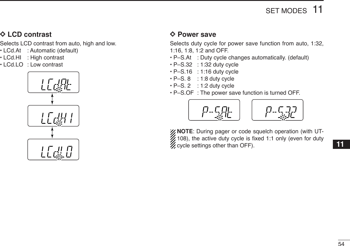
![5311 SET MODESDDSquelch delaySelects squelch delay from short and long to prevent re-peated opening and closing of the squelch during receptionof the same signal.•Sqt. S : The squelch closes in short delay. (default)•Sqt. L : The squelch closes in long delay.DDDTMF rateThe rate at which DTMF memories send individual DTMFcharacters can be set to accommodate operating needs.•1: 100 msec. interval; 5.0 cps rate (default)•2: 200 msec. interval; 2.5 cps rate •3: 300 msec. interval; 1.6 cps rate •5: 500 msec. interval; 1.0 cps rate (cps=characters/sec.)DDDial assignmentSelects [VOL] control action from volume and tuning dial.•tOP.VO: AF volume (default)•tOP.dI : Tuning dial DDDisplay typeSelects LCD indication type from frequency, channel numberand channel names.•dSP.FR : Shows frequency (default)•dSP.CH : Shows channel number*•dSP.nm : Shows channel names†*Only memory channels can be selected.† Frequency indication will be displayed when the selected memorychannel has no programmed memory name. NOTE: When this setting is selected other than “FR” (“CH”or “nm”) and accessing SET MODEfrom memory mode,most of set mode items are restricted.](https://usermanual.wiki/ICOM-orporated/296400/User-Guide-745010-Page-66.png)
![5511 SET MODESDDMonitor key actionThe monitor key, [MONI], can be set as a ‘sticky’ key. Whenset to the sticky condition, each push of [MONI] toggles themonitor function ON and OFF.•PU (Push) : Pushing and holding [MONI] to monitor the fre-quency. (default)•HO (Hold) : Push [MONI] to monitor the frequency and pushagain to cancel it.DDTuning speed accelerationThe tuning speed acceleration automatically speeds up thetuning speed when pushing and holding [YY]or [ZZ], or rotat-ing [VOL] rapidly.*•S–S.At : The tuning speed acceleration is activated. (de-fault)•S–S. m : The tuning speed acceleration is not activated. *When tuning dial is assigned with [VOL].DDMic simple modeThis item turns the microphone simple mode ON and OFF.Microphone simple mode is used to change the function as-signments for keys in the optional HM-75AREMOTE CONTROLSPEAKER-MICROPHONEas below. This assignment is conve-nient for 3-channel use of simple operation.•mIC.n1 : Normal 1 (default)•mIC.n2 : Normal 2•mIC.Sm: Simple modeA1750 Hz tone can be transmitted with the HM-75A opera-tion. ➥Push [A] while pushing [PTT]. Optional HM-75A requiredHM-75A Mode NORMAL1 NORMAL2 SIMPLEkey[A] Freq. [CALL] [MONI] [MONI]CH Null[B] Freq. VFO/Memory VFO/Memory [CALL]CH Null Null[YY]Freq. Freq. Up Freq. Up MR-00CHCH Memory CH Up Memory CH Up[ZZ]Freq. Freq. Down Freq. Down MR-01CHCH Memory CH Down Memory CH Down](https://usermanual.wiki/ICOM-orporated/296400/User-Guide-745010-Page-68.png)
![5611SET MODES12345678910111213141516171819NOTE:Turn power OFF when connecting the HM-75A to thetransceiver.VFO mode cannot be selected via the microphone whenSIMPLE mode is selected.DDBattery protection functionSets the Battery protection function from LI (Li-Ion) (default)and OFF.LI(Li-Ion):➥The transceiver does not memorized the transceiverON/OFF condition when battery is detached, and automat-ically returns to OFF condition even if you detach the bat-tery with the transceiver ON condition. You are required toturn ON the transceiver by pushing [PWR] for every bat-tery attach.➥Beep sounds when the attached battery is exhaustion.•The battery must be charged presently.OFF : The transceiver memorizes the transceiver ON/OFFcondition when battery is detached.NOTE: This item MUST be set “LI” (Li-Ion) when the at-taching battery is BP-227 (Li-Ion).](https://usermanual.wiki/ICOM-orporated/296400/User-Guide-745010-Page-69.png)
![57SET MODE INSPECTION12SET MODE• Weather alert* (p. 50)• Repeater tone frequency (p. 47) • Tone squelch frequency (p. 47) • DTCS code (p. 48) • DTCS polarity (p. 48)• Offset frequency (p. 48)• Reverse function (p. 48)• Tuning step (p. 48)• Scan pause timer (p. 49)• Function key timer (p. 49)• LCD backlight (p. 49)• Tx permission (p. 49)• Bank link function† (p. 50)• Bank setting† (p. 50)*Available for [USA] version only.†Appears when accessing SET MODE from memory mode only.: Push: PushPush , then push to enter SET MODE (p. 47).AFUNC8SETNOTE: When the display type setting (pgs. 20, 53) in INITIAL SET MODE is selected other than “FR” (“CH” or “nm”) and accessing SET MODE from memory mode, most of set mode items are restricted.](https://usermanual.wiki/ICOM-orporated/296400/User-Guide-745010-Page-70.png)
![5812SET MODE INSPECTION12345678910111213141516171819INITIAL SET MODE• Battery protection function (p. 56)• Mic simple mode (p. 55)• Key touch beep (p. 51) • Time-out timer (p. 51) • Auto repeater* (p. 52) • Auto power-off (p. 52)• Squelch delay (p. 53)• DTMF rate (p. 53)• Repeater lock-out (p. 52)• Dial assignment (p. 53)• Display type (p. 53)• LCD contrast (p. 54)• Power save (p. 54)• Tuning speed acceleration (p. 55)• Monitor key action (p. 55)*Available for [USA] version only.: Push: PushWhile pushing and holding , push to enter INITIAL SET MODE (p. 51).PWR](https://usermanual.wiki/ICOM-orporated/296400/User-Guide-745010-Page-71.png)
![59CLONING13qConnect the OPC-474 CLONING CABLEto the [SP] jack ofthe master and sub-transceivers. •The master transceiver is used to send data to the sub-trans-ceiver.wWhile pushing [FUNC] and [YY], turn power ON to entercloning mode (master transceiver only— power ON forsub-transceiver).•“CLONE” appears and thetransceivers enter the clonestandby condition.DUP SCANPRIOSETH/M/LOPTSKIPBANKTONET.SCANP.BEEPABDCCALLENTMR CLRFUNCPWR9874123560AFUNCPWRMaster transceiverSub transceiverCloning allows you to quickly and easily transfer the pro-grammed contents from one transceiver to another trans-ceiver.■Transceiver-to-transceiver cloningATPOWER ON](https://usermanual.wiki/ICOM-orporated/296400/User-Guide-745010-Page-72.png)
![6013CLONING12345678910111213141516171819Please refer to the HELP file that comes with CS-V85CLONING SOFTWARE.■Cloning using a PCPCTRANSCEIVERto USB portto USB portto RS-232C portOPC-478(RS-232C type)OPC-478U (USB type)OPC-478UC(USB type)ePush [PTT] on the mastertransceiver.•“CL OU” appears in the mastertransceiver’s display and S-meter indicator shows thatdata is being transferred tothe sub-transceiver.•“CL In” appears automatically in the sub-transceiver’s display andS-meter indicator shows that data is being received from themaster transceiver.rWhen cloning is finished, turn power OFF, then ON againto exit cloning mode.NOTE: DO NOT push [PTT] on the sub-transceiver duringcloning. This will cause a cloning error.DUP SCANPRIOSETH/M/LOPTSKIPBANKTONET.SCANP.BEEPABDCCALLENTMR CLRFUNCPWR9874123560](https://usermanual.wiki/ICOM-orporated/296400/User-Guide-745010-Page-73.png)
![61RESETTING FUNCTIONS14■Partial resetIf you want to initialize the operating conditions (VFO fre-quency, VFO settings, set mode contents) without clearingthe memory contents, a partial resetting function is availablefor the transceiver.➥While pushing [CLR], push and hold [PWR] for 1 sec. topartially reset.■CPU resetThe function display may occasionally display erroneous in-formation (e.g. when first applying power). This may becaused externally by static electricity or by other factors.If this problem occurs, turn power OFF. After waiting a fewseconds, turn power ON again. If the problem persists, per-form the following procedure.•Partial resetting is also available. See left for details.IMPORTANT!:Resetting the transceiver CLEARS all memory informationand initializes all values in the transceiver.➥While pushing [MONI] and [CLR], push and hold [PWR]for 1 sec. to reset the CPU.•“CLEAR” indicates, then initial display appears.DUP SCANPRIOSETH/M/LOPTSKIPBANKTONET.SCANP.BEEPABDCCALLENTMR CLRFUNCPWR9874123560CLRDMONIPWRATPOWER ONDUP SCANPRIOSETH/M/LOPTSKIPBANKTONET.SCANP.BEEPABDCCALLENTMR CLRFUNCPWR9874123560CLRDPWRATPOWER ON](https://usermanual.wiki/ICOM-orporated/296400/User-Guide-745010-Page-74.png)
![6215TROUBLESHOOTING12345678910111213141516171819PROBLEMNo power comes ON.No sound comes from thespeaker.Transmitting is impossible.No contact possible withanother station.Frequency can not be set.Program scan functioncan not start.Memory scan function cannot start.The displayed frequency iserroneous.Can not charge the batterywith BC-167A/D.If your transceiver seems to be malfunctioning, please check the following points before sending it to a service center.POSSIBLE CAUSE• The batteries are exhausted.• The battery polarity is reversed.• The BP-227 becomes hot.(Battery’s protection circuit may activate.)• Volume level is too low.• Different tone is selected with tone/DTCSsquelch.• The batteries are exhausted.• Different tone is selected with tone/DTCSsquelch.• The key lock function is activated.• Memory mode or call channel is selected.• Memory mode or call channel is selected.• Same frequencies are programmed both “✱A”and “✱b” of scan edge memory channel.• VFO mode or call channel is selected.• The programmed memory channel is onlyone.• The CPU malfunctioned.• External factors caused a fault.• Turn the transceiver’s power ON.SOLUTION• Replace the batteries or charge the battery pack.• Check the battery polarity.• Cool down the BP-227. • Rotate [VOL] to suitable level.• Check the tone using tone/DTCS scan.• Replace the batteries or charge the battery pack.• Check the tone/DTCS using tone scan.• Push [FUNC] then push and hold [](✱ENT)for 1 sec. to cancel the function.• Push [CLR] to set VFO mode.• Push [CLR] to set VFO mode.• Programming different frequencies in “✱A” and“✱b” respectively.• Push [MR] to set memory mode.• Program more than 2 memory channels.• Reset the transceiver.• Remove and re-attach the battery pack or batterycase.• Turn the transceiver’s power OFF, then connectthe BC-167A/D to charge.REF.pgs. 9, 13–15p. 10–p. 19p. 42pgs. 9, 13–15p. 42p. 20p. 17p. 17p. 27p. 26p. 27p. 61p. 9pgs. 13 ,17](https://usermanual.wiki/ICOM-orporated/296400/User-Guide-745010-Page-75.png)
![6417SPECIFICATIONS12345678910111213141516171819■General•Frequency coverage : (unit: MHz)USA Tx: 144–148/Rx: 136–174*1Europe, UK Tx: 144–146/Rx: 136–174*2Taiwan, Thailand, Korea Tx/Rx: 144–146General (LM) Tx/Rx: 136–174*1*1: Guaranteed: 144–148 MHz range only*2: Guaranteed: 144–146 MHz range only•Type of emission : FM•Number of memory channels : 107 (incl. 6 scan edges and 1 call)•Frequency resolution : 5, 10, 12.5, 15, 20, 25, 30, 50 kHz•Operating temperature range : –10°C to +60°C; +14˚F to +140˚F•Frequency stability : ±2.5 ppm(–10°C to +60°C; +14˚F to +140˚F)•Power supply requirement :Supplied (or optional) Icom’s batterypack or 11.0 V±15% external DC power•Current drain : (at 7.2 V DC: approx.)Transmit at 7 W (High) 2.6 Aat 4 W (Middle) 2.0 Aat 0.5 W (Low) 1.0 AReceive standby 80 mApower save 30 mAmax. audio 250 mA•Antenna connector : BNC (50 Ω)•Dimensions (proj. not included) :56(W) ×110(H) ×34.4(D) mm27⁄32(W)×411⁄32(H)×111⁄32(D) in(with BP-227)•Weight (approx.) : 310 g; 12.5 oz (with BP-227 and Ant.)165 g; 5.8 oz (without battery pack and Ant.)■Transmitter•Modulation system : Variable reactance frequency mod.•Output power (at 7.2 V) : [Thailand] 5.5 W/4 W/0.5 W (High/Mid/Low)[Others] 7 W/4 W/0.5 W (High/Mid/Low)•Max. frequency deviation : ±5.0 kHz •Spurious emissions : Less than –60 dBc•Microphone connector :3-conductor 2.5 (d) mm (1⁄10″)/2.2 kΩ■Receiver•Receive system : Double-conversion superheterodyne•Intermediate frequencies : 1st: 46.35 MHz, 2nd: 450 kHz•Sensitivity (at 12 dB SINAD) :Less than 0.2 µV•Squelch sensitivity (threshold) :Less than 0.16 µV•Selectivity : More than 55 dB•Spurious and image rejection : More than 60 dB•Intermodulation : More than 55 dB•Audio output power :More than 0.3 W at 10% distortion with(at 7.2 V DC)an 8 Ωload•Ext. speaker connector : 3-conductor 3.5 (d) mm (1⁄8″)/8 ΩAll stated specifications are subject to change without notice or obligation.](https://usermanual.wiki/ICOM-orporated/296400/User-Guide-745010-Page-77.png)