ICOM orporated 296400 Scanning Receiver User Manual
ICOM Incorporated Scanning Receiver Users Manual
Users Manual

INSTRUCTION MANUAL
This device complies with Part 15 of the FCC Rules. Operation is
subject to the following two conditions: (1) this device may not cause
harmful interference, and (2) this device must accept any interference
received, including interference that may cause undesired operation.
iV85
FM TRANSCEIVER
iV85E
iV85-T

i
FOREWORD
Thank you for purchasing this Icom transceiver. The IC-V85
FM TRANSCEIVER
is designed and built with Icom’s superior
technology and craftsmanship. With proper care, this trans-
ceiver should provide you with years of trouble-free operation.
We want to take a couple of moments of your time to thank
you for making the IC-V85 your radio of choice, and hope you
agree with Icom’s philosophy of “technology first.” Many hours
of research and development went into the design of your IC-
V85.
DD
FEATURES
❍7W*— high transmit output power
*7 W : IC-V85 except [THA] version,
5.5 W : IC-V85 [THA] version
❍CTCSS and DTCS encoder/decoder stan-
dard
❍Optional DTMF decoder
IMPORTANT
READ ALL INSTRUCTIONS carefully and completely
before using the transceiver.
SAVE THIS INSTRUCTION MANUAL— This in-
struction manual contains important operating instructions for
the IC-V85.
EXPLICIT DEFINITIONS
WORD DEFINITION
RWARNING!
CAUTION
NOTE
Personal injury, fire hazard or electric shock
may occur.
Equipment damage may occur.
Recommended for optimum use. No risk of
personal injury, fire or electric shock.
Icom, Icom Inc. and the logo are registered trademarks of Icom
Incorporated (Japan) in the United States, the United Kingdom, Ger-
many, France, Spain, Russia and/or other countries.

ii
RWARNING RF EXPOSURE! This device emits
Radio Frequency (RF) energy. Extreme caution should be ob-
served when operating this device. If you have any questions
regarding RF exposure and safety standards please refer to
the Federal Communications Commission Office of Engi-
neering and Technology’s report on Evaluating Compliance
with FCC Guidelines for Human Radio frequency Electro-
magnetic Fields (OET Bulletin 65)
RWARNING! NEVER hold the transceiver so that the
antenna is very close to, or touching exposed parts of the
body, especially the face or eyes, while transmitting. The
transceiver will perform best if the microphone is 5 to 10 cm
(2 to 4 inches) away from the lips and the transceiver is verti-
cal.
RWARNING! NEVER operate the transceiver with a
headset or other audio accessories at high volume levels.
Hearing experts advise against continuous high volume op-
eration. If you experience a ringing in your ears, reduce the
volume or discontinue use.
RWARNING! NEVER operate the transceiver while
driving a vehicle. Safe driving requires your full attention—
anything less may result in an accident.
RWARNING! NEVER connect the transceiver to an AC
outlet. This may pose a fire hazard or result in an electric shock.
NEVER connect a power supply of more than 16 V DC
through the optional CP-19R
CIGARETTE LIGHTER CABLE
to the
[DC 11V] jack to prevent damaging the transceiver.
NEVER connect the transceiver to a power source using
reverse polarity. This will ruin the transceiver.
NEVER cut the DC power cable between the DC plug and
fuse holder. If an incorrect connection is made after cutting,
the transceiver may be damaged.
NEVER expose the transceiver to rain, snow or any liquids.
The transceiver may be damaged.
NEVER operate or touch the transceiver with wet hands.
This may result in an electric shock or ruin the transceiver.
NEVER attempt to charge alkaline or dry cell batteries. Be
aware that external DC power connections will charge batter-
ies inside the battery case. This will damage not only the bat-
tery case but also the transceiver.
DO NOT push the PTT when not actually desiring to trans-
mit.
PRECAUTIONS
iii
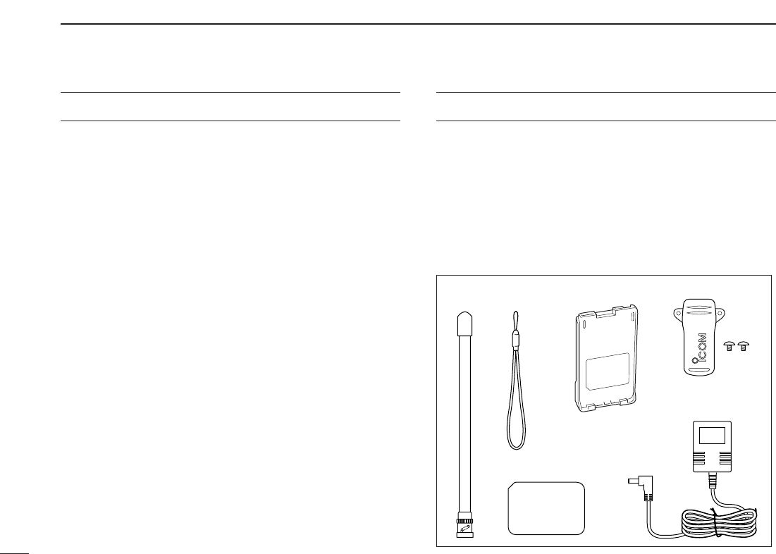
SUPPLIED ACCESSORIES
qAntenna* . . . . . . . . . . . . . . . . . . . . . . . . . . . . . . . . . . . . . 1
wHand strap* . . . . . . . . . . . . . . . . . . . . . . . . . . . . . . . . . . . 1
e2251 OPT sheet*. . . . . . . . . . . . . . . . . . . . . . . . . . . . . . . 1
rBattery pack*/Battery case* . . . . . . . . . . . . . . . . . . . . . . 1
tBelt clip* (with screws) . . . . . . . . . . . . . . . . . . . . . . . . . . 1
yAC Adapter*. . . . . . . . . . . . . . . . . . . . . . . . . . . . . . . . . . . 1
*Not supplied with some versions.
y
qw t
e
r
DO NOT operate the transceiver near unshielded electrical
blasting caps or in an explosive atmosphere.
BE CAREFUL! The transceiver will become hot when
operating it continuously for long periods.
AVOID using or placing the transceiver in direct sunlight or
in areas with temperatures below –10°C (+14˚F) or above
+60°C (+140˚F).
Place the unit in a secure place to avoid inadvertent use by
children.
AVOID the use of chemical agents such as benzine or al-
cohol when cleaning, as they can damage the transceiver’s
surfaces.
Even when the transceiver power is OFF, a slight current still
flows in the circuits. Remove the battery pack or case from
the transceiver when not using it for a long time. Otherwise,
the battery pack (Li-Ion: BP-227) or installed batteries will be-
come exhausted.
For USA only:
Caution: Changes or modifications to this transceiver, not ex-
pressly approved by Icom Inc., could void your authority to
operate this transceiver under FCC regulations.
PRECAUTIONS—continued

iv
• BP-226
BATTERY CASE
Battery case for 5×AA (LR6) size alkaline batteries.
• BP-227
LI
-
ION BATTERY PACK
7.2 V/1700 mAh Lithium-Ion battery pack.
• BC-119N
DESKTOP CHARGER
+ AD-100
CHARGER ADAPTER
For rapid charging of battery packs. An AC adapter is sup-
plied with the charger. Charging time: approx. 2–2.5 hrs.
• BC-121N
MULTI
-
CHARGER
+ AD-100
CHARGER ADAPTER
(6 pcs.)
For rapid charging of up to 6 battery packs (six AD-100’s are
required) simultaneously. An AC adapter may be supplied
depending on version. Charging time: approx. 2–2.5 hrs.
• CP-19R
CIGARETTE LIGHTER CABLE WITH NOISE FILTER
Used for operation and charging a battery pack connected
to transceiver via a DC power source. (11.7 V–15.9 V DC)
• MB-98
BELT CLIP
MB-98: Same as that supplied with the transceiver.
• UT-108
DTMF DECODER UNIT
Provides pager and code squelch capabilities.
• SP-13
EARPHONE
Provides clear receive audio in noisy environments.
• FA-B2E
WHIP ANTENNA
Same as that supplied with transceiver.
• HM-75A/HM-131L/HM-158L
SPEAKER
-
MICROPHONES
Combination speaker-microphones that provide convenient
operation while hanging the transceiver from your belt.
HM-75A has 4 function switches for remote control capabilities.
HM-131L/HM-158L are equipped with an earphone jack and
a revolving clip.
• HM-128L/HM-153L/HM-166
EARPHONE
-
MICROPHONE
You can clip the microphone with PTT switch to your lapel or
breast pocket.
• HS-85
HEADSET
Allows you hands-free operation. Includes VOX, PTT and
“one-touch” PTT with time-out timer.
• VS-1L
PTT
/
VOX UNIT
+HS-94
HEADSET
VS-1L
PTT
/
VOX UNIT
Required when using the headset.
HS-94
EAR
-
PIECE TYPE HEADSET
Earhook headset with flexible boom microphone.
• CS-V85
CLONING SOFTWARE
+OPC-478/U/UC
CLONING CABLE
Provide quick and easy programming of memory channel,
memory name etc.
• OPC-474
CLONING CABLE
For cloning between transceivers.
• LC-167
CARRYING CASE
Helps protect the transceiver from scratches, etc..
OPTION LIST

v
TABLE OF CONTENTS
FOREWORD ........................................................................ i
IMPORTANT......................................................................... i
EXPLICIT DEFINITIONS...................................................... i
PRECAUTIONS .............................................................. ii–iii
SUPPLIED ACCESSORIES ............................................... iii
OPTION LIST .................................................................... iv
TABLE OF CONTENTS .................................................. v–vi
QUICK REFERENCE GUIDE ......................................... I–VI
■Preparation................................................................... I
■Your first contact ........................................................ IV
■Repeater operation ..................................................... V
■Programming memory channels................................ VI
1 ACCESSORIES.......................................................... 1–2
■Accessory attachment................................................. 1
2PANEL DESCRIPTION .............................................. 3–8
■Switches, controls, keys and connectors .................... 3
■Function display .......................................................... 7
3BATTERY PACKS.................................................... 9–16
■Battery pack replacement ........................................... 9
■Cautions .................................................................... 11
■Regular charging ...................................................... 13
■Rapid charging ......................................................... 14
■External DC power operation .................................... 16
4BASIC OPERATION............................................... 17–21
■Power ON.................................................................. 17
■VFO mode selection.................................................. 17
■Setting a frequency ................................................... 17
■Setting audio/squelch level ....................................... 19
■Receive and transmit ................................................ 19
■Monitor function......................................................... 19
■Display type............................................................... 20
■Key lock function ....................................................... 20
■Weather channel operation
(USA version only) .................................................... 21
5REPEATER OPERATION ...................................... 22–25
■General ..................................................................... 22
■Reversed duplex mode ............................................. 22
■Offset frequency........................................................ 23
■Subaudible tones ...................................................... 23
■Repeater lockout ....................................................... 24
■Auto repeater function (USA version only) ................ 25
6MEMORY/CALL OPERATION ............................... 26–31
■General description ................................................... 26
■Selecting a memory channel..................................... 26
■Selecting the call channel ......................................... 26
■Programming the memory/call channels................... 27
■Channel name programming..................................... 28
■Memory transfers ...................................................... 28

vi
1
2
3
4
5
6
7
8
9
10
11
12
13
14
15
16
17
18
19
■Memory bank selection ............................................. 30
■Memory bank setting................................................. 30
■Transferring bank contents........................................ 31
7DTMF MEMORY..................................................... 32–34
■Programming a DTMF code sequence ..................... 32
■Transmitting a DTMF code sequence ....................... 33
■DTMF transmission rate............................................ 34
8SCAN OPERATION................................................ 35–38
■Scan types ................................................................ 35
■Programmed scan..................................................... 35
■Memory scan..............................................................36
■Skip channels............................................................ 37
■Scan resume condition.............................................. 37
■Priority watch............................................................. 38
9SUBAUDIBLE TONES........................................... 39–42
■Tone squelch ............................................................. 39
■Pocket beep operation .............................................. 41
■Tone scan.................................................................. 42
10PAGER/CODE SQUELCH
(Requires Optional UT-108).................................. 43–46
■Pager function ........................................................... 43
■Code programming ................................................... 43
■Pager operation......................................................... 45
■Code squelch ............................................................ 46
11 SET MODES........................................................... 47–56
■SET MODE ............................................................... 47
■INITIAL SET MODE .................................................. 51
12SET MODE INSPECTION ...................................... 57–58
13CLONING ............................................................... 59–60
■Transceiver-to-transceiver cloning ............................ 59
■Cloning using a PC ................................................... 60
14RESETTING FUNCTIONS ........................................... 61
■Partial reset ............................................................... 61
■CPU reset.................................................................. 61
15TROUBLESHOOTING ................................................. 62
16OPTION ........................................................................ 63
■Optional UT-108 installation ...................................... 63
17SPECIFICATIONS........................................................ 64
■General ..................................................................... 64
■Transmitter ................................................................ 64
■Receiver .................................................................... 64
18CE........................................................................... 65–66
I
QUICK REFERENCE GUIDE
■Preparation
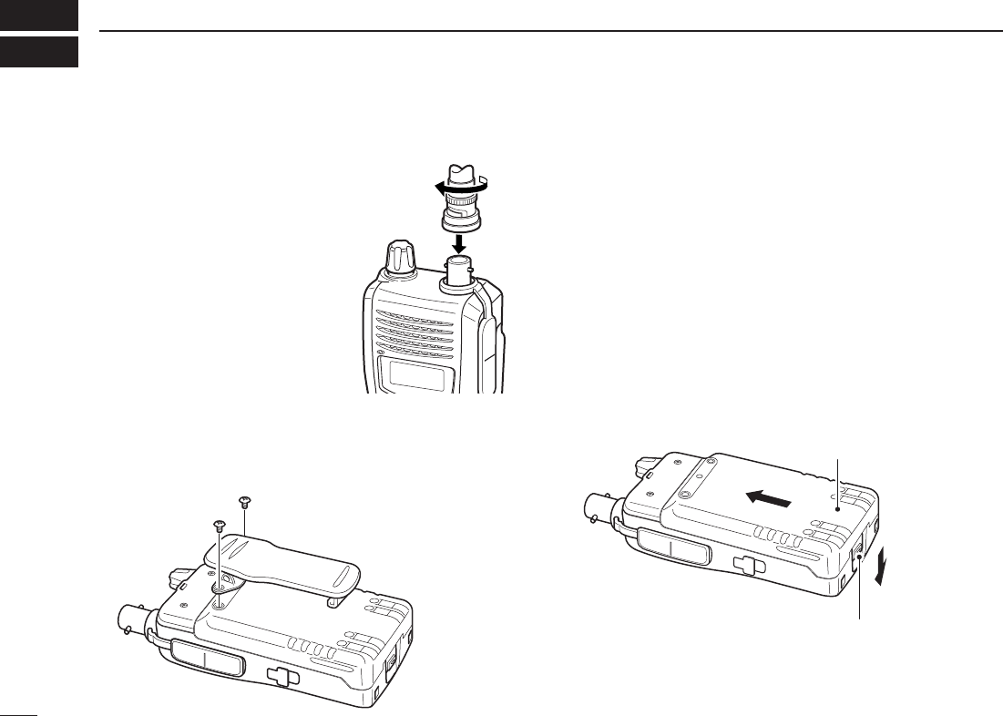
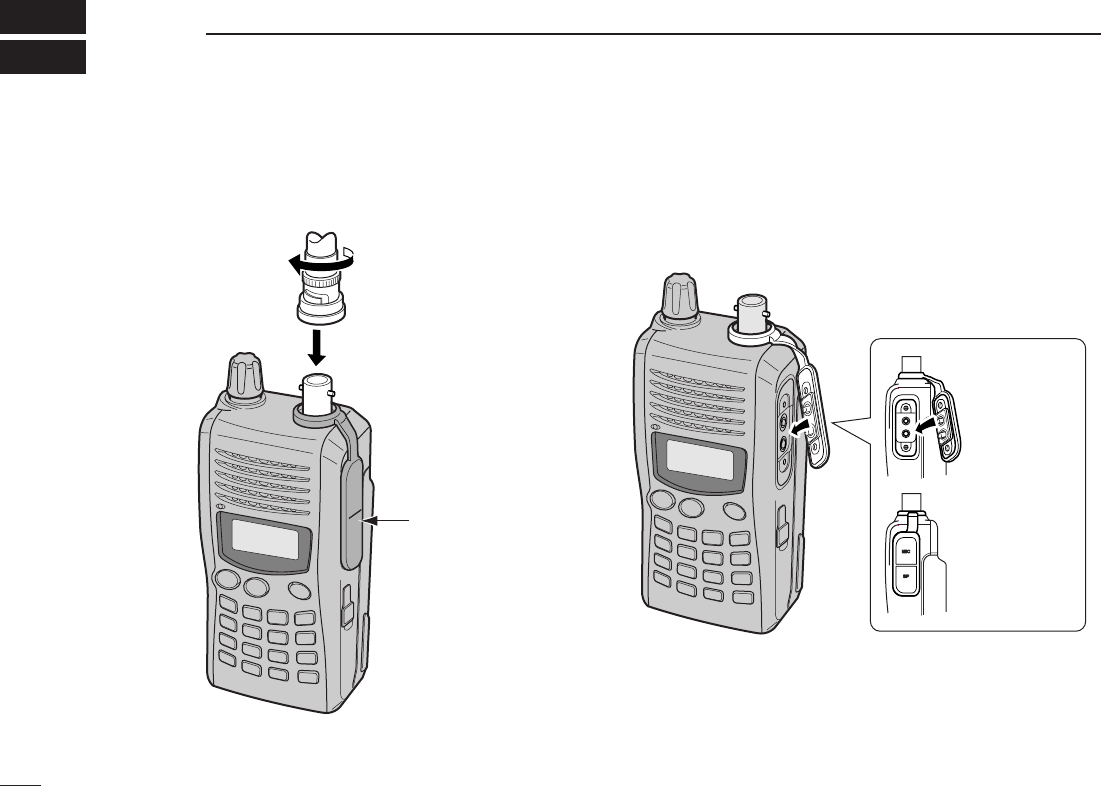
DAntenna
Attach the antenna to the transceiver
as illustrated at right.
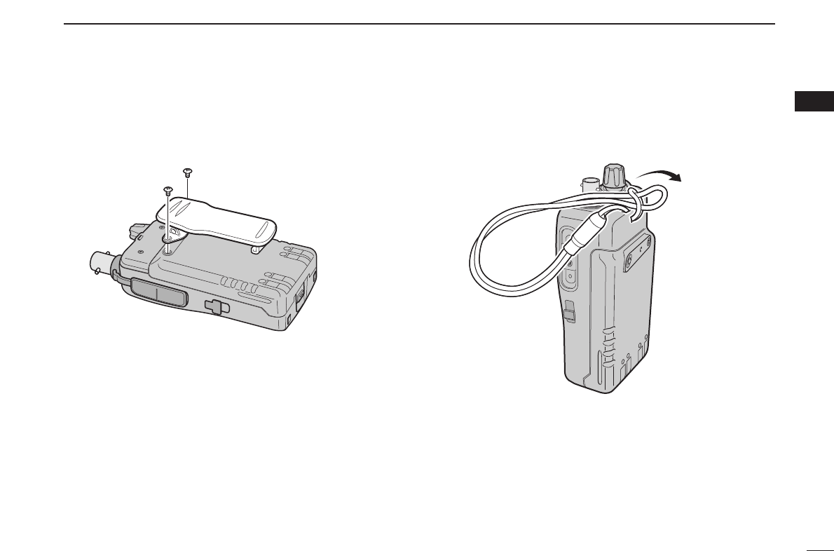
DBelt clip
Conveniently attaches to your belt.
Attach the belt clip with the supplied screws using a phillips
screwdriver.
DBattery pack replacement
Before replacing the battery pack, push and hold [PWR] for 1
sec. to turn the power OFF.
• To attach the battery pack
Slide the battery pack on the back of the transceiver in the di-
rection of the arrow (q), then lock it with the battery release
button.
•Slide the battery pack until the battery release button makes a ‘click’
sound.
• To release the battery pack
Push the battery release button in the direction of the arrow
(w) as shown below. The battery pack is then released.
w
q
Battery pack
Battery release button
To attach the belt clip
II
QUICK REFERENCE GUIDE
Quick reference guide
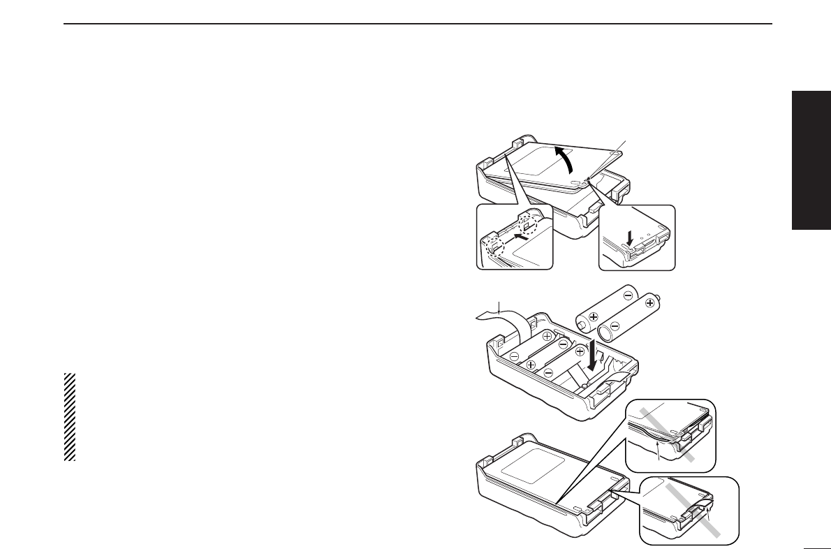
DBattery case— optional for some versions
When using a BP-226
BATTERY CASE
attached to the trans-
ceiver, install 5 AA (LR6) size alkaline batteries as illustrated
at right.
qHook your finger under the latch, and open the cover in the
direction of the arrow (q). (Fig.1)
wThen, install 5 ×AA (LR6) size alkaline batteries. (Fig.2)
• Install the alkaline batteries only.
• Be sure to observe the correct polarity.
• Do not pin the ribbon under the batteries.
eClose the cover with fitting in the direction of the arrow (w)
first, then firm the latch in place (e). (Fig.1)
• Be sure to the gasket and the ribbon are set correctly,
and do not protrude out of the battery case. (Fig.3)
RCAUTION!
•When installing batteries, make sure they are all the
same brand, type and capacity. Also, do not mix new and
old batteries together.
•Keep battery contacts clean. It’s a good idea to clean bat-
tery terminals once a week.
q
we
BP-226 Latch
Fig.1
Fig.2
Ribbon
Fig.3
Gasket
Ribbon

III
QUICK REFERENCE GUIDE
DDRegular charging
When using a BP-227
BATTERY PACK
attached to the trans-
ceiver, prior to using the transceiver for the first time, the bat-
tery pack must be fully charged for optimum life and
operation.
DDCharging note
•Be sure to turn the transceiver power OFF.
Otherwise the battery pack will not be charged completely or takes
longer charging time periods.
•External DC power operation becomes possible when using
an optional CP-19R. The attached battery pack is also
charged simultaneously, except during transmit. (see p. 16
for more details)
Even through there is no indication during regular charg-
ing, the transceiver automatically stops charging the bat-
tery pack when the battery pack is fully charged (BP-227’s
voltage becomes approx. 7.2 V) or the continuous charg-
ing time is over 15 hours.
• BC-167A/D
• CP-19R (Optional)
to AC outlet
to cigarette lighter
socket (12 V DC)
Transceiver
to
[DC 11V]
Turn power OFF
while charging the
battery pack.
• Charging time period:
Approx. 12–13 hours
■Your first contact
Now that you have your IC-V85 ready, you are excited to get
on the air. We would like to walk you through a few basic op-
erational steps to make your first “On The Air” use an enjoy-
able experience.
DAbout default setting
The [VOL] control function can be exchanged with [YY]/[ZZ]
keys function in
INITIAL SET MODE
. However, in this QUICK
REFERENCE, the factory default setting ([VOL] controls
audio output level) is used to simplify instructions.
DBasic operation
1. Turning ON the transceiver
Although you have purchased a brand new transceiver, some
settings may be changed from the factory defaults because
of the Quality Control
process. Resetting the CPU
is necessary to start from
factory default.
➥While pushing [MONI]
and [CLR], push and
hold [PWR] for 1 sec. to
reset the CPU and turn
power ON.
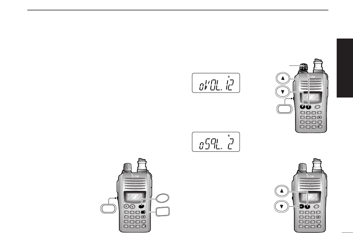
2. Adjusting audio output level
➥Rotate [VOL] to set the desired
audio level.
3. Adjusting the squelch level
➥While pushing and holding
[MONI], push [YY]or [ZZ]to set
the squelch level.
4. Tune the desired frequency
The up/down keys, [YY]/[ZZ], will
allow you to tune to the frequency
that you want to operate on. Page
18 will instruct you on how to adjust
the tuning step size.
➥Push [YY]or [ZZ]to adjust the fre-
quency.
IV
QUICK REFERENCE GUIDE
DUP SCAN
PRIO
SET
H/M/L
OPT
SKIP
BANK
TONE
T.SCAN
P.BEEP
ABD
C
CALL
ENT
MR CLRFUNC
PWR
9
8
7
4
123
560
CLR
D
MONI
PWR
DUP SCAN
PRIO
SET
H/M/L
OPT
SKIP
BANK
TONE
T.SCAN
P.BEEP
ABD
C
CALL
ENT
MR CLRFUNC
PWR
9
8
7
4
123
560
MONI
[VOL]
DUP SCAN
PRIO
SET
H/M/L
OPT
SKIP
BANK
TONE
T.SCAN
P.BEEP
ABD
C
CALL
ENT
MR CLRFUNC
PWR
9
8
7
4
123
560
Quick reference guide
V
QUICK REFERENCE GUIDE
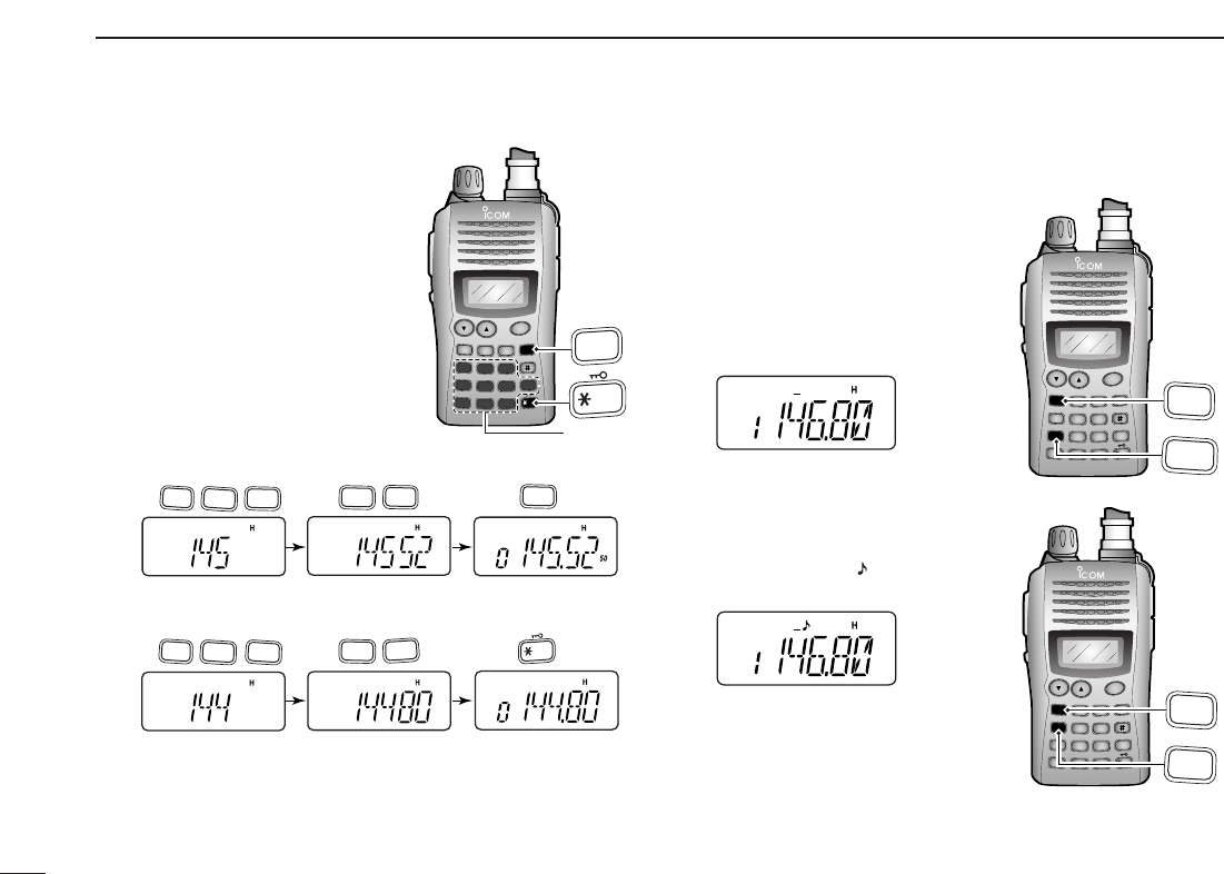
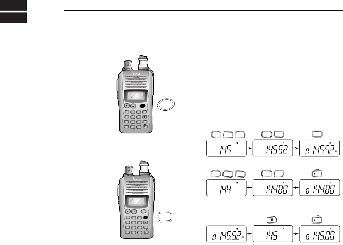
Direct frequency input from the
keypad is also available.
➥To enter the desired frequency,
enter 6 digits starting from the
100 MHz digit.
•Entering three* to five digits then
pushing [✱
ENT
]will also set the fre-
quency. (*Some versions only re-
quires two digits.)
•When a digit is mistakenly input,
push [CLR] to abort input.
5. Transmit and receive
➥Push and hold [PTT] to transmit, then speak into the mi-
crophone; release to receive.
■Repeater operation
1. Setting duplex
➥Push [FUNC], then [
DUP
](4) sev-
eral times to select minus duplex
or plus duplex.
•The USA version has an auto re-
peater function, therefore, setting du-
plex is not required.
2. Repeater tone
➥Push [FUNC], then [
TONE
](1) sev-
eral times until “ ” appears, if re-
quired.
DUP SCAN
PRIO
SET
H/M/L
OPT
SKIP
BANK
TONE
T.SCAN
P.BEEP
ABD
C
CALL
ENT
MR CLRFUNC
PWR
9
8
7
4
123
560
A
FUNC
1
TONE
DUP SCAN
PRIO
SET
H/M/L
OPT
SKIP
BANK
TONE
T.SCAN
P.BEEP
ABD
C
CALL
ENT
MR CLRFUNC
PWR
9
8
7
4
123
560
A
4
FUNC
DUP
• Example 1— when entering 145.525 MHz
Push
• Example 2— when entering 144.800 MHz
Push
1
TONE
4
DUP
1
TONE
4
DUP
4
DUP
2
P.BEEP
5
SCAN
5
SCAN
5
SCAN
8
SET
0
OPT
ENT
DUP SCAN
PRIO
SET
H/M/L
OPT
SKIP
BANK
TONE
T.SCAN
P.BEEP
ABD
C
CALL
ENT
MR CLRFUNC
PWR
9
8
7
4
123
560
ENT
D
CLR
Keypad
VI
QUICK REFERENCE GUIDE
Quick reference guide
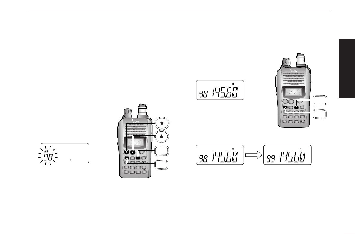
The IC-V85 has a total of 107 memory channels (including 6
scan edges and 1 call channel) for storing often used operat-
ing frequency, repeater settings, etc.
1. Setting frequency
In VFO mode, set the desired operating frequency with other
desired settings, such as repeater and subaudible tone.
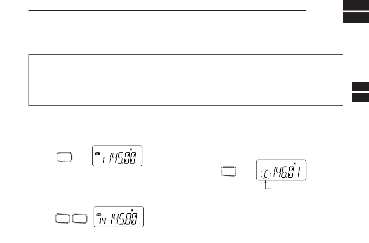
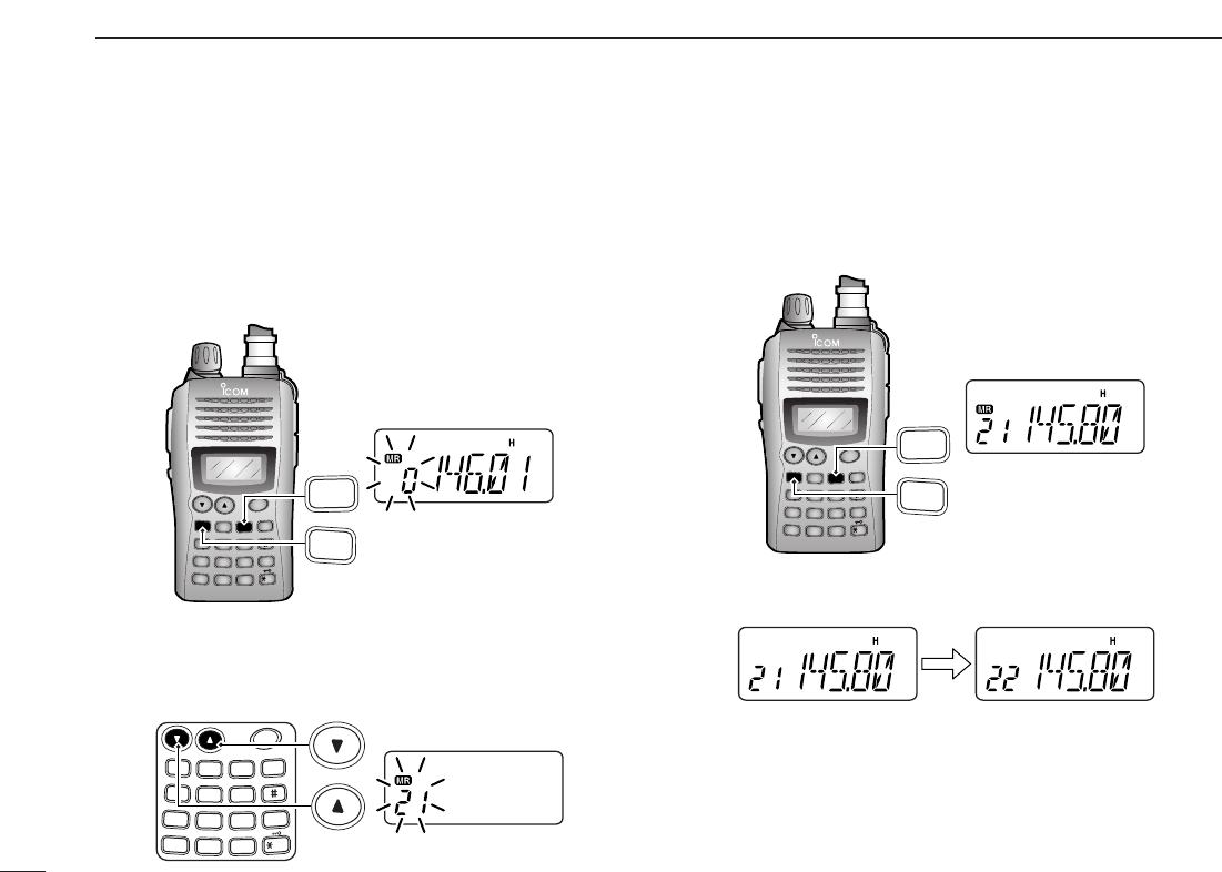
2. Selecting a memory channel
➥Push [FUNC] and [MR] then push
[YY] or [ZZ]several times to select
the desired memory channel.
•“
X” indicator and memory channel
number blink.
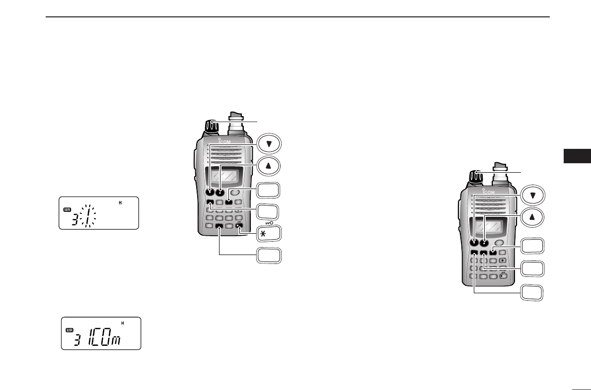
3. Writing a memory channel
➥Push [FUNC], then push and hold
[MR] for 1 sec. to program.
•3 beeps sound.
•Continue to push and hold [MR] for 1 sec. after 3 beeps are emit-
ted, to increment the displayed memory channel number.
DUP SCAN
PRIO
SET
H/M/L
OPT
SKIP
BANK
TONE
T.SCAN
P.BEEP
ABD
C
CALL
ENT
MR CLRFUNC
PWR
9
8
7
4
123
560
A
FUNC
C
MR
DUP SCAN
PRIO
SET
H/M/L
OPT
SKIP
BANK
TONE
T.SCAN
P.BEEP
ABD
C
CALL
ENT
MR CLRFUNC
PWR
9
8
7
4
123
560
A
FUNC
C
MR
■Programming memory channels
1
ACCESSORIES
1
■Accessory attachment
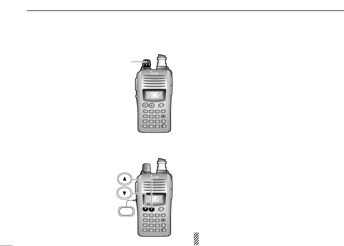
DAntenna
Attach the antenna to the transceiver as illustrated below. Keep the [SP/MIC] cap (SP/MIC jack cover) attached when
jacks are not in use to keep the contacts clean.
Attach the
[SP/MIC] cap.
[SP/MIC] cap
2
1
ACCESSORIES
1
2
3
4
5
6
7
8
9
10
11
12
13
14
15
16
17
18
19
DBelt clip
Conveniently attaches to your belt.
Attach the belt clip with the supplied screws using a phillips
screwdriver.
DHand strap
Slide the hand strap through the loop on the top of the rear panel
as illustrated below. Facilitates carrying.
To attach the belt clip
3
PANEL DESCRIPTION
2
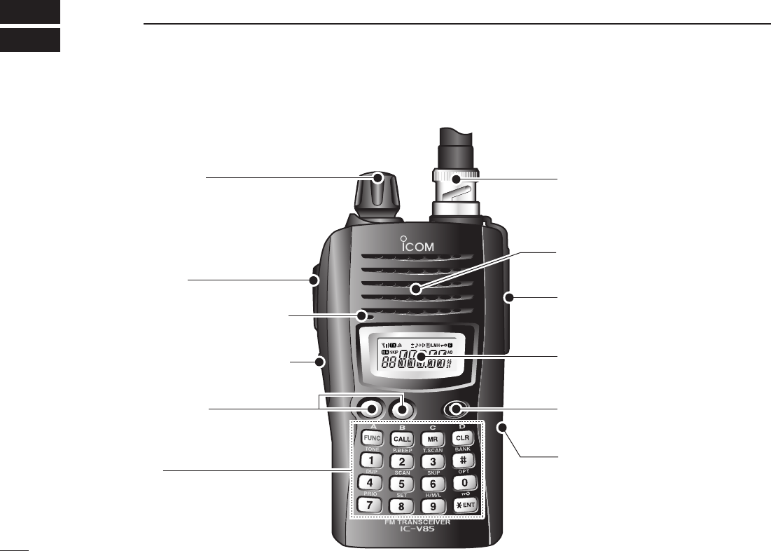
■Switches, controls, keys and connectors
q!0
o
u
i
w
e
r
Speaker
Microphone
CONTROL DIAL ANTENNA CONNECTOR
EXTERNAL SPEAKER/
MICROPHONE JACKS
FUNCTION DISPLAY
POWER KEY
EXTERNAL DC JACK
PTT SWITCH
UP/DOWN KEYS
KEYPAD
SQUELCH/MONITOR SWITCH
ty

4
2
PANEL DESCRIPTION
1
2
3
4
5
6
7
8
9
10
11
12
13
14
15
16
17
18
19
qCONTROL DIAL [VOL] (p. 19)
Rotate to adjust the volume level.
The assigned function for [VOL] and [YY]/[ZZ]can be ex-
changed in
INITIAL SET MODE
(pgs. 18, 53).
wPTT SWITCH [PTT]
Push and hold to transmit; release to receive.
eSQUELCH/MONITOR SWITCH [MONI] (p. 19)
➥Push and hold to open the squelch temporarily and
monitor the operating frequency.
➥While pushing and holding this key, push [YY]or [ZZ]to
adjust the squelch level.
The assigned function for [VOL] and [YY]/[ZZ]can be
exchanged in
INITIAL SET MODE
(pgs. 18, 53).
rUP/DOWN KEYS [YY]/[ZZ](p.18)
Selects the operating frequency, set mode items, etc.
The assigned function for [VOL] and [YY]/[ZZ]can be ex-
changed in
INITIAL SET MODE
(pgs. 18, 53).
tKEYPAD (pgs. 5, 6)
Used to enter operating frequency, the DTMF codes, etc.
yEXTERNAL DC JACK [DC 11V]
➥Connect an external DC power supply through the op-
tional CP-19R for external DC operation. (p. 16)
➥Connect the supplied (or optional) wall charger, BC-
167A/D, to charge the attached battery pack. (p. 13)
uPOWER KEY [PWR] (p. 17)
Push and hold for 1 sec. to turn the power ON and OFF.
iFUNCTION DISPLAY (pgs. 7, 8)
oEXTERNAL SPEAKER/MICROPHONE JACKS [SP/MIC]
Connect an optional speaker-microphone or headset, if de-
sired. The internal microphone and speaker will not func-
tion when a connector is inserted.
See page iv for a list of available options.
!0 ANTENNA CONNECTOR (p. 1)
Connects the supplied antenna.

5
2PANEL DESCRIPTION
DKeypad
[FUNC]
Access to secondary function.
[CALL]
Selects the call channel. (p. 26)
[MR]
➥Selects a memory mode. (p. 26)
➥After pushing [FUNC], enter into memory pro-
gramming/editing mode. (pgs. 27–29)
➥After pushing [FUNC], programs/transfers
VFO/memory or call channel contents into
memory channel/VFO when pushed and held
for 1 sec. (pgs. 27–29)
[CLR]
Selects VFO mode, aborts direct frequency input,
or cancels scanning, etc. (pgs. 17, 35)
[1•
TONE
]
➥Input digit “1” during frequency input, memory
channel selection, etc. (pgs. 17, 26)
➥After pushing [FUNC], selects the subaudible
tone function. (pgs. 22, 39)
[2•
P
.
BEEP
]
➥Input digit “2” during frequency input, memory
channel selection, etc. (pgs. 17, 26)
➥After pushing [FUNC], turns the pocket beep
function ON and OFF. (p. 41)
[3•
T
.
SCAN
]
➥Input digit “3” during frequency input, memory
channel selection, etc. (pgs. 17, 26)
➥After pushing [FUNC], starts tone scanning.
(pgs. 24, 42)
[4•
DUP
]
➥Input digit “4” during frequency input, memory
channel selection, etc. (pgs. 17, 26)
➥After pushing [FUNC], selects duplex function
(–duplex, +duplex, simplex). (p. 22)
[5•
SCAN
]
➥Input digit “5” during frequency input, memory
channel selection, etc. (pgs. 17, 26)
➥After pushing [FUNC], starts scanning. (p. 35)
5
SCAN
4
DUP
3
T.SCAN
2
P.BEEP
1
TONE
D
CLR
C
MR
B
CALL
A
FUNC
A
1
4
7
FUNC
TONE
DUP
PRIO
B
2
5
8
CALL
P.BEEP
SCAN
SET
C
3
6
9
SKIP
T.SCAN
MR
H
/
M
/
L
D
0
CLR
BANK
OPT
ENT

6
2
PANEL DESCRIPTION
1
2
3
4
5
6
7
8
9
10
11
12
13
14
15
16
17
18
19
[6•
SKIP
]
➥Input digit “6” during frequency input, memory
channel selection, etc. (pgs. 17, 26)
➥After pushing [FUNC], sets and cancels skip
setting for memory scan during memory mode.
(p. 37)
[7•
PRIO
]
➥Input digit “7” during frequency input, memory
channel selection, etc. (pgs. 17, 26)
➥After pushing [FUNC], starts priority watch.
(p. 38)
[8•
SET
]
➥Input digit “8” during frequency input, memory
channel selection, etc. (pgs. 17, 26)
➥After pushing [FUNC], enters into
SET MODE
.
(p. 47)
[9•
H
/
M
/
L
]
➥Input digit “9” during frequency input, memory
channel selection, etc. (pgs. 17, 26)
➥After pushing [FUNC], switches transmit power
between high, middle and low output power.
(p. 19)
When the transceiver becomes hot during
high or middle output power operation, the
built-in protection circuit activates to reduce
the transmit output power to 3 W (approx.).
[0•
OPT
]
➥Input digit “0” during frequency input, memory
channel selection, etc. (pgs. 17, 26)
➥After pushing [FUNC], selects an optional func-
tion mode, such as pager or code squelch op-
eration. (pgs. 45, 46)
[#•
BANK
]
After pushing [FUNC], enters a memory bank se-
lection. (p. 30)
[✱
ENT
•]
➥Sets the frequency even if the full 6 digits of
frequency have not been entered. (p. 17)
➥After pushing [FUNC], switches key lock func-
tion ON and OFF when pushed and held for 1
sec. Lock all keys, except [PWR], [PTT],
[MONI] and audio level adjustment. (p. 20)
ENT
BANK
0
OPT
9
H
/
M
/
L
8
SET
7
PRIO
6
SKIP
7
2PANEL DESCRIPTION
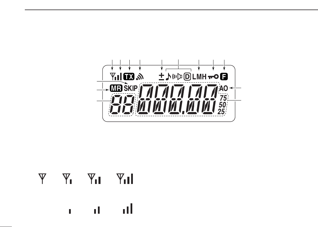
qBUSY INDICATOR
➥Appears when a signal is being received or the squelch
is open.
➥Blinks while the monitor function is activated. (p. 19)
wSIGNAL INDICATOR
➥Shows receiving signal strength as below.
➥Shows the output power level while transmitting.
eTRANSMIT INDICATOR (p. 19)
Appears during transmit.
rPAGER CALL INDICATOR (p. 46)
Blinks when a pager call is received. (This indicator ap-
pears only when an optional UT-108
DTMF DECODER UNIT
is installed.)
tDUPLEX INDICATOR (p. 23)
“+” appears when plus duplex, “–” appears when minus
duplex is selected.
Low Middle High
Weak ⇐ RX Signal level ⇒ Strong
q
qq
wq
r
q
eq
tq
uq
iq
oy
!0
!1
!3
!4
!2
■Function display

8
2
PANEL DESCRIPTION
1
2
3
4
5
6
7
8
9
10
11
12
13
14
15
16
17
18
19
yTONE INDICATOR
➥“” appears while the subaudible tone encoder is in
use. (p. 23)
➥“” appears while the tone (CTCSS) squelch function
is in use. (p. 39)
➥“” appears while the tone (DTCS) squelch function is
in use. (p. 39)
➥“” appears with the “ ” or “ ” indicator while the
pocket beep function (CTCSS or DTCS) is in use.
(p. 41)
uOUTPUT POWER INDICATOR (p. 19)
➥“L” appears when the low output power is selected.
➥“M” appears when the middle output power is selected.
➥“H” appears when high output power is selected.
iKEY LOCK INDICATOR (p. 20)
Appears when the key lock function is ON.
oFUNCTION INDICATOR
Appears while a secondary function is being accessed.
!0AUTO POWER OFF INDICATOR (p. 52)
Appears while the auto power OFF function is activated.
!1 FREQUENCY READOUT
Shows operating frequency, channel number or channel
names, depending on display type (p. 20).
!2 MEMORY CHANNEL INDICATOR (p. 26)
➥Shows the selected memory channel number.
➥“C” appears when the call channel is selected.
!3 MEMORY MODE INDICATOR (p. 26)
Appears while in memory mode or channel number indica-
tion mode.
!4 SKIP CHANNEL INDICATOR (p. 37)
Appears when the selected memory channel is specified
as a skip channel.
9
BATTERY PACKS
3
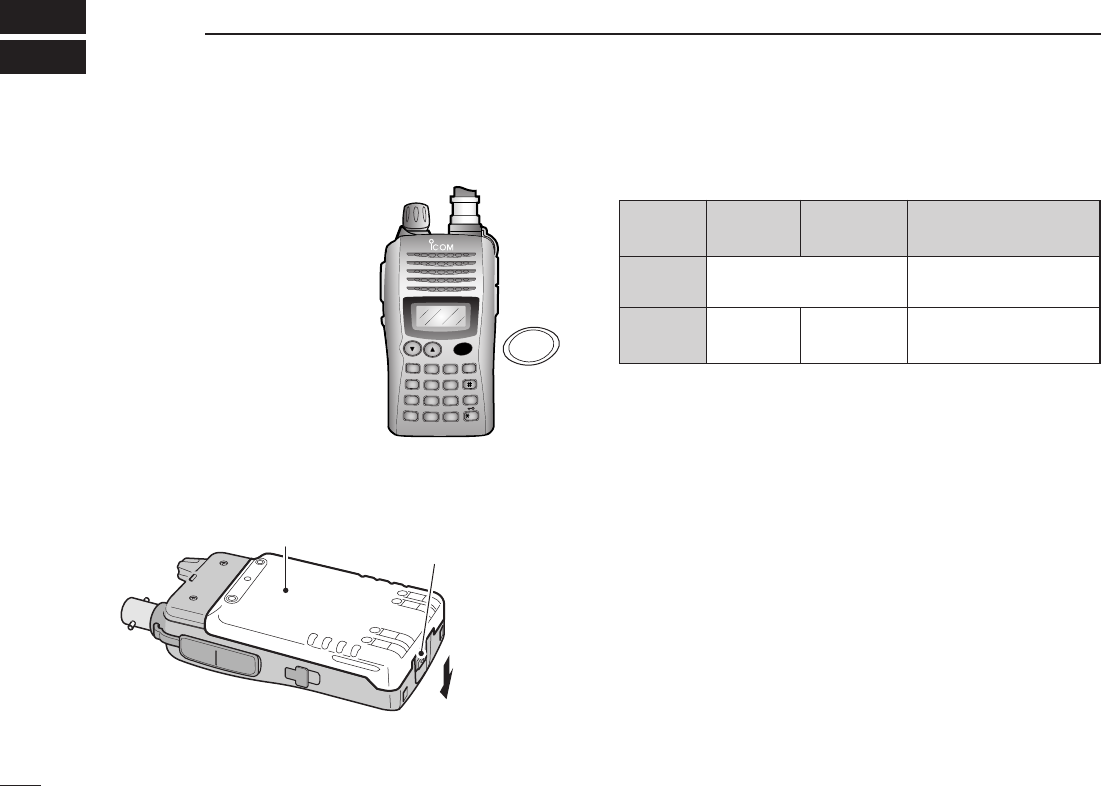
■Battery pack replacement
qBefore replacing the battery
pack, push and hold [PWR]
for 1 sec. to turn the power
OFF.
wPush the battery release button in the direction of the
arrow as shown below. The battery pack is then released.
DDBattery packs
*1Operating periods are calculated under the following conditions;
Tx : Rx : standby =1 : 1 : 8, power save function: auto setting is
activated
*2Operating period depends on the alkaline cells used.
Battery pack Battery release button
DUP SCAN
PRIO
SET
H/M/L
OPT
SKIP
BANK
TONE
T.SCAN
P.BEEP
ABD
C
CALL
ENT
MR CLRFUNC
PWR
9
8
7
4
123
560
PWR
Battery Voltage Capacity Battery life*1
pack
BP-226 Battery case for AA —*2
(LR6)×5 alkaline
BP-227 7.2 V 1700 mAh 7 hrs.
10
3
BATTERY PACKS
1
2
3
4
5
6
7
8
9
10
11
12
13
14
15
16
17
18
19
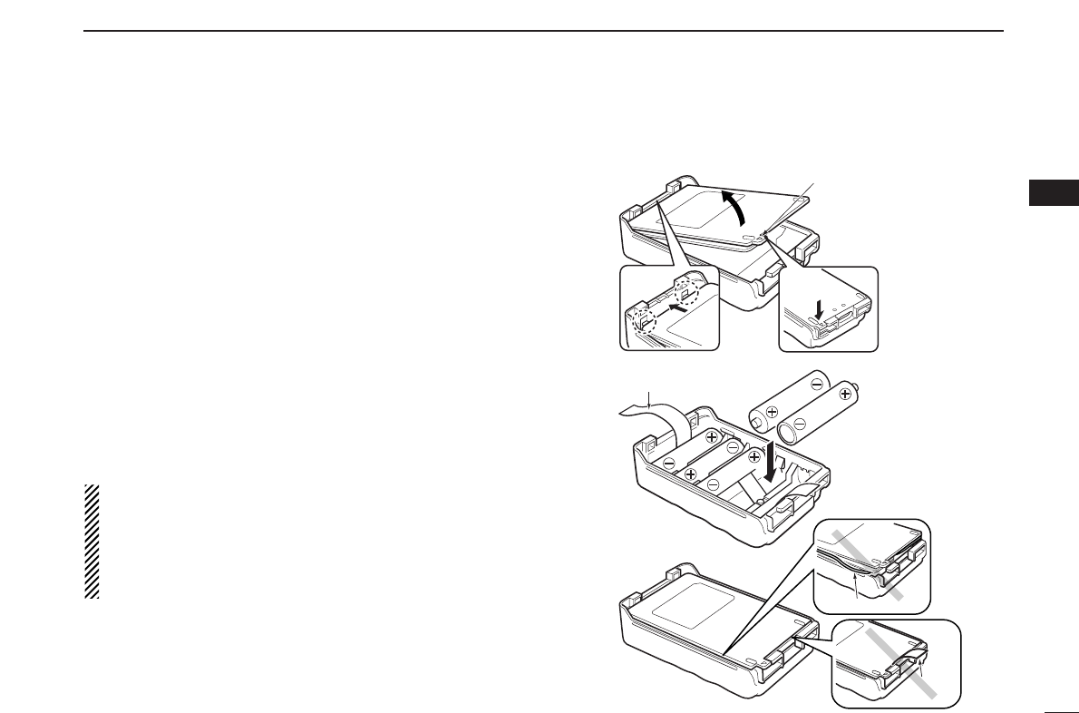
DBattery case— optional for some versions
When using a BP-226
BATTERY CASE
attached to the trans-
ceiver, install 5 AA (LR6) size alkaline batteries as illustrated
at right.
qHook your finger under the latch, and open the cover in the
direction of the arrow (q). (Fig.1)
wThen, install 5 ×AA (LR6) size alkaline batteries. (Fig.2)
• Install the alkaline batteries only.
• Be sure to observe the correct polarity.
• Do not pin the ribbon under the batteries.
eClose the cover with fitting in the direction of the arrow (w)
first, then firm the latch in place (e). (Fig.1)
• Be sure to the gasket and the ribbon are set correctly,
and do not protrude out of the battery case. (Fig.3)
RCAUTION!
•When installing batteries, make sure they are all the
same brand, type and capacity. Also, do not mix new and
old batteries together.
•Keep battery contacts clean. It’s a good idea to clean bat-
tery terminals once a week.
q
we
BP-226 Latch
Fig.1
Fig.2
Ribbon
Fig.3
Gasket
Ribbon

11
3BATTERY PACKS
■Cautions
•RDANGER! Use and charge only specified Icom battery
packs with Icom radios. Only Icom battery packs are tested
and approved for use with Icom radios. Using third-party or
counterfeit battery packs may cause smoke, fire, or cause
the battery to burst.
DDBattery caution
•RDANGER! DO NOT hammer or otherwise impact the bat-
tery. Do not use the battery if it has been severely impacted
or dropped, or if the battery has been subjected to heavy
pressure. Battery damage may not be visible on the outside
of the case. Even if the surface of the battery does not show
cracks or any other damage, the cells inside the battery may
rupture or catch fire.
•RDANGER! NEVER use or leave battery pack in areas
with temperatures above +60˚C (+140˚F). High temperature
build up in the battery, such as could occur near fires or
stoves, inside a sun heated car, or in direct sunlight may
cause the battery to rupture or catch fire. Excessive temper-
atures may also degrade battery performance or shorten
battery life.
•RDANGER! DO NOT expose the battery to rain, snow,
seawater, or any other liquids. Do not charge or use a wet
battery. If the battery gets wet, be sure to wipe it dry before
using.
•RDANGER! NEVER incinerate an used battery pack since
internal battery gas may cause it to rupture, or may cause
an explosion.
•RDANGER! NEVER solder the battery terminals, or
NEVER modify the battery pack. This may cause heat gen-
eration, and the battery may burst, emit smoke or catch fire.
•RDANGER! Use the battery only with the transceiver for
which it is specified. Never use a battery with any other
equipment, or for any purpose that is not specified in this in-
struction manual.
•RDANGER! If fluid from inside the battery gets in your
eyes, blindness can result. Rinse your eyes with clean
water, without rubbing them, and see a doctor immediately.
•WARNING! Immediately stop using the battery if it emits an
abnormal odor, heats up, or is discolored or deformed. If any
of these conditions occur, contact your Icom dealer or dis-
tributor.
•WARNING! Immediately wash, using clean water, any part
of the body that comes into contact with fluid from inside the
battery.
Misuse of Lithium-Ion batteries may result in the follow-
ing hazards: smoke, fire, or the battery may rupture.
Misuse can also cause damage to the battery or degra-
dation of battery performance.

12
3
BATTERY PACKS
1
2
3
4
5
6
7
8
9
10
11
12
13
14
15
16
17
18
19
•WARNING! NEVER put the battery in a microwave oven,
high-pressure container, or in an induction heating cooker.
This could cause a fire, overheating, or cause the battery to
rupture.
•CAUTION! Always use the battery within the specified tem-
perature range for the transceiver (–10˚C to +60˚C; +14˚F
to +140˚F) and the battery itself (–10˚C to +60˚C; +14˚F to
+140˚F). Using the battery out of its specified temperature
range will reduce the battery’s performance and battery life.
•CAUTION! Shorter battery life could occur if the battery is
left fully charged, completely discharged, or in an excessive
temperature environment (above +45˚C; +113˚F) for an ex-
tended period of time. If the battery must be left unused for a
long time, it must be detached from the radio after discharg-
ing. You may use the battery until the battery becomes
about half-capacity, then keep it safely in a cool dry place
with the temperature between –20˚C to +35˚C (–4˚F to
+95˚F).
DDCharging caution
•RDANGER! NEVER charge the battery pack in areas with
extremely high temperatures, such as near fires or stoves,
inside a sun heated car, or in direct sunlight. In such envi-
ronments, the safety/protection circuit in the battery will acti-
vate, causing the battery to stop charging.
•WARNING! DO NOT charge or leave the battery in the bat-
tery charger beyond the specified time for charging. If the
battery is not completely charged by the specified time, stop
charging and remove the battery from the battery charger.
Continuing to charge the battery beyond the specified time
limit may cause a fire, overheating, or the battery may rup-
ture.
•WARNING! NEVER insert the transceiver (battery attached
to the transceiver) into the charger if it is wet or soiled. This
could corrode the battery charger terminals or damage the
charger. The charger is not waterproof.
•CAUTION! DO NOT charge the battery outside of the spec-
ified temperature range: 10˚C to +40˚C (+50˚F to +104˚F).
Icom recommends charging the battery at +20˚C (+68˚F).
The battery may heat up or rupture if charged out of the
specified temperature range. Additionally, battery perfor-
mance or battery life may be reduced.
13
3BATTERY PACKS
■Regular charging
When using a BP-227
BATTERY PACK
attached to the trans-
ceiver, prior to using the transceiver for the first time, the bat-
tery pack must be fully charged for optimum life and
operation.
DDCharging note
•Be sure to turn the transceiver power OFF.
Otherwise the battery pack will not be charged completely or takes
longer charging time periods.
•External DC power operation becomes possible when using
an optional CP-19R. The attached battery pack is also
charged simultaneously, except during transmit. (see p. 16
for more details)
Even through there is no indication during regular charg-
ing, the transceiver automatically stops charging the bat-
tery pack when the battery pack is fully charged (BP-227’s
voltage becomes approx. 7.2 V) or the continuous charg-
ing time is over 15 hours.
• BC-167A/D
• CP-19R (Optional)
to AC outlet
to cigarette lighter
socket (12 V DC)
Transceiver
to
[DC 11V]
Turn power OFF
while charging the
battery pack.
• Charging time period:
Approx. 12–13 hours
14
3
BATTERY PACKS
1
2
3
4
5
6
7
8
9
10
11
12
13
14
15
16
17
18
19
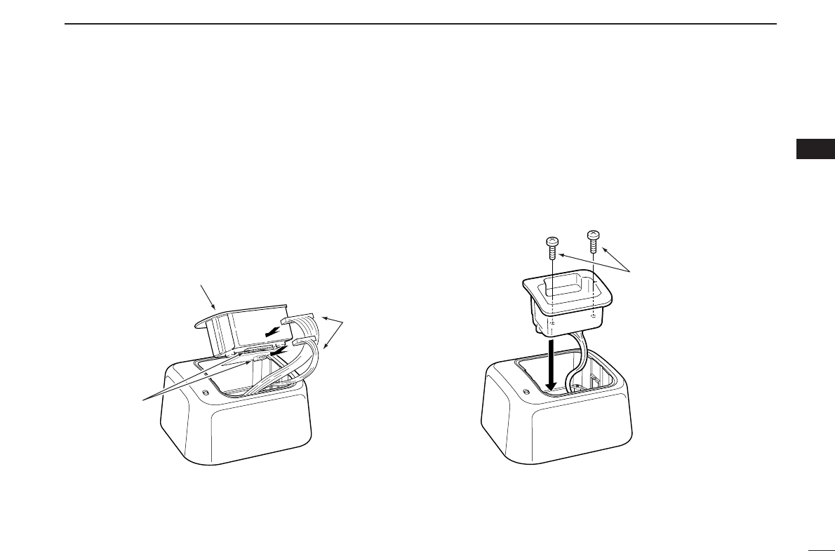
Screws supplied with
the charger adapter
Desktop charger adapter
Connectors
BC-119N
AD-100
Plugs
■Rapid charging
DAD-100 installation
Install the AD-100 desktop charger adapter into the holder
space of the BC-119N/121N.
Connect the plugs of the BC-119N/121N to the AD-100 desk-
top charger adapter with the connector, then install the
adapter into the charger with the supplied screws.
15
3BATTERY PACKS
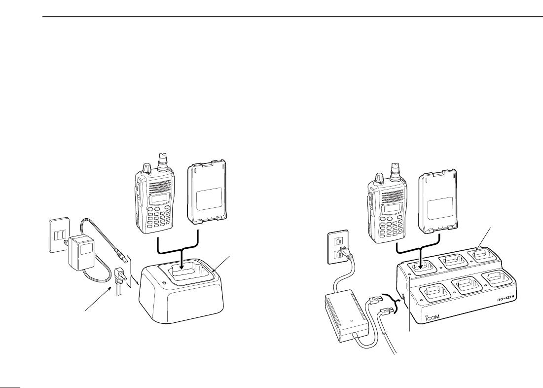
DRapid charging with the BC-119N+AD-100
The optional BC-119N provides rapid charging of battery
packs. The following items are additionally required.
• AD-100 (Charger Adapter).
• An AC adapter (may be supplied with the BC-119N depending on
version) or the DC power cable (OPC-515L/CP-17L).
DRapid charging with the BC-121N+AD-100
The optional BC-121N allows up to 6 battery packs to be
charged simultaneously. The following items are additionally
required.
• Six AD-100 (Charger Adapter).
• An AC adapter (BC-157; may be supplied with the BC-121N de-
pending on version) or the DC power cable (OPC-656).
MULTI-CHARGER
Turn power OFF.
Battery packTransceiver
AC adapter
(purchased
separately)
AD-100 charger
adapters are installed
in each slot.
DC power cable (OPC-656)
(Connect with the DC power supply; 13.8 V/at least 7 A)
Charge indicator
(each indicator functions independently)
AC adapter
(Not supplied with
some versions.)
OPC-515L or
CP-17L
AD-100 charger
adapter is instal-
led in BC-119N.
Optional OPC-515L (for 13.8 V
power source) or CP-17L (for
12 V cigarette lighter socket)
can be used instead of the AC
adapter.
Turn power OFF.
Battery packTransceiver
16
3
BATTERY PACKS
1
2
3
4
5
6
7
8
9
10
11
12
13
14
15
16
17
18
19
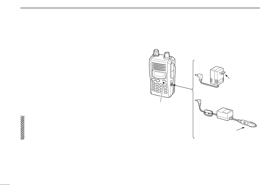
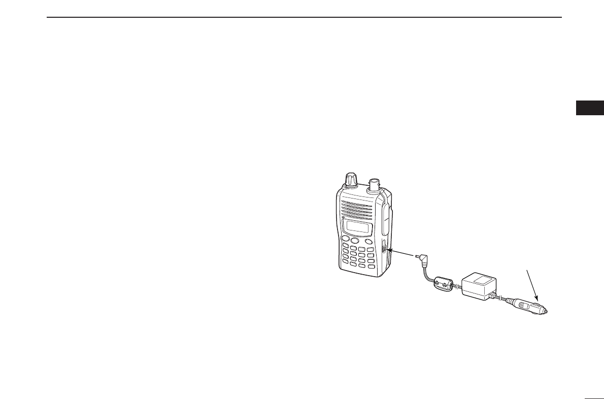
■External DC power operation
An optional cigarette lighter cable (CP-19R; for 12 V cigarette
lighter socket) can be used for external power operation.
DDOperating note
•BE SURE to use optional CP-19R when connecting a regu-
lated 12 V DC power supply into the [DC 11V] jack of the
transceiver.
•The voltage of the external power supply must be within
11.7–15.9 V DC when using CP-19R.
•NEVER CONNECT OVER 16 V DC through CP19R.
Use an external DC-DC converter to connect the transceiver
through CP-19R to a 24 V DC power source.
•Disconnect the power cables from the transceiver when not
using it. Otherwise, the vehicle battery will become ex-
hausted.
•The power save function is deactivated automatically during
external DC power operation.
CP-19R (Optional)
to cigarette lighter
socket (12 V DC)
Transceiver
to
[DC 11V]
17
BASIC OPERATION
4
■Power ON
➥Push and hold [PWR] for 1
sec. to turn power ON.
■VFO mode selection
The transceiver has 2 basic oper-
ating modes: VFO mode and
memory mode.
➥Push [CLR] to select VFO
mode.
■Setting a frequency
DVia the keypad
qPush [CLR] to select VFO mode, if necessary.
wTo enter the desired frequency, enter 6 digits starting from
the 100 MHz digit.
•Entering three* to five digits then pushing [✱
ENT
]will also set
the frequency. (*Some versions only requires two digits.)
•When changing 100 kHz and below, push [#] then enter the de-
sired digits.
•When a digit is mistakenly input, push [CLR] to abort input.
• Example 1— when entering 145.525 MHz
Push
• Example 2— when entering 144.800 MHz
Push
• Example 3— when entering 145.000 MHz
Push
1
TONE
4
DUP
1
TONE
4
DUP
4
DUP
2
P.BEEP
5
SCAN
5
SCAN
5
SCAN
8
SET
0
OPT
ENT
ENT
BANK
from 145.525 MHz
DUP SCAN
PRIO
SET
H/M/L
OPT
SKIP
BANK
TONE
T.SCAN
P.BEEP
ABD
C
CALL
ENT
MR CLRFUNC
PWR
9
8
7
4
123
560
D
CLR
DUP SCAN
PRIO
SET
H/M/L
OPT
SKIP
BANK
TONE
T.SCAN
P.BEEP
ABD
C
CALL
ENT
MR CLRFUNC
PWR
9
8
7
4
123
560
PWR
18
4
BASIC OPERATION
1
2
3
4
5
6
7
8
9
10
11
12
13
14
15
16
17
18
19
DBy other methods
Via the [YY]/[ZZ] keys
➥Push [YY]or [ZZ]several times to set the desired frequency.
•Each push increases/decreases the frequency by the selected
tuning step. See next set of instructions for setting tuning step
size.
DTuning step selection
The IC-V85 has 8 tuning steps—
5, 10, 12.5, 15, 20, 25, 30 and
50 kHz. The tuning step is selec-
table in
SET MODE
.
qPush [FUNC] then [
SET
](8) to
enter
SET MODE
.
wPush [YY]or [ZZ]several times
to select the tuning step item.
eRotate [VOL] to select the desired tuning step.
rPush [✱
ENT
](or [CLR]) to exit
SET MODE
.
DUP SCAN
PRIO
SET
H/M/L
OPT
SKIP
BANK
TONE
T.SCAN
P.BEEP
ABD
C
CALL
ENT
MR CLRFUNC
PWR
9
8
7
4
123
560
[VOL]
A
FUNC
8
SET
ENT
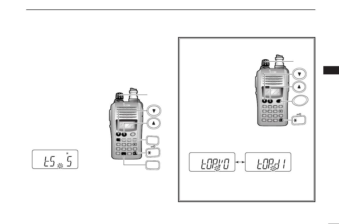
✔For your information— [VOL] function assignment
The [VOL] control can be
used as a tuning dial for fre-
quency tuning instead of
[YY]/[ZZ]keys. However, when
[VOL] functions as tuning
dial, [YY]/[ZZ]keys function as
volume control.
qWhile pushing and holding
[YY]and [ZZ], turn power
ON to enter
INITIAL SET
MODE
.
wPush [YY]or [ZZ]several
times to select the dial as-
signment item, “tOP.”
eRotate [VOL] to select the condition.
rTo exit
INITIAL SET MODE
, push [✱
ENT
](or [CLR]).
[VOL] is assigned as
AF volume control. [VOL] is assigned as
tuning dial.
DUP SCAN
PRIO
SET
H/M/L
OPT
SKIP
BANK
TONE
T.SCAN
P.BEEP
ABD
C
CALL
ENT
MR CLRFUNC
PWR
9
8
7
4
123
560
[VOL]
PWR
ENT
19
4BASIC OPERATION
■Setting audio/squelch level
DTo set the audio level
Rotate [VOL] to set the desired
audio level while receiving a
signal.
• When no signal is received, push
and hold [MONI] while setting the
audio level.
• When [VOL] is assigned as tun-
ing dial, push [YY]/[ZZ]to adjust
the audio output level. (pgs. 18,
53)
DTo set the squelch level
While pushing [MONI], push
[YY]/[ZZ]to set the squelch
level.
• The squelch level “10” is tight
squelch, “1” is loose squelch and
“0” is open squelch.
• When [VOL] is assigned as tun-
ing dial, rotate [VOL] while press-
ing [MONI]. (pgs. 18, 53)
■Receive and transmit
qPush and hold [PWR] for 1 sec. to turn the power ON.
wAdjust audio volume to the desired level.
eSet the frequency.
When a signal is received:
• Squelch opens and audio is emitted from the speaker.
• Signal indicator shows the relative signal strength level.
rPush [FUNC], then [
H
/
M
/
L
](9) to select output power be-
tween high, middle and low.
•“H” appears when high power is selected.
•“M” appears when middle power is selected.
•“L” appears when low power is selected.
tPush and hold [PTT] to transmit, then speak into the micro-
phone.
• “
$
” appears.
•Do not hold the microphone too close to your mouth or
speak too loudly. This may distort the signal.
yRelease [PTT] to receive.
■Monitor function
This function is used to listen to weak signals without disturb-
ing the squelch setting or to open the squelch manually even
when mute functions such as the tone squelch are in use.
➥Push and hold [MONI] to monitor the operating frequency.
The [MONI] key can be set to ‘sticky’ operation in
INITIAL
SET MODE
. See page 55 for details.
DUP SCAN
PRIO
SET
H/M/L
OPT
SKIP
BANK
TONE
T.SCAN
P.BEEP
ABD
C
CALL
ENT
MR CLRFUNC
PWR
9
8
7
4
123
560
MONI
DUP SCAN
PRIO
SET
H/M/L
OPT
SKIP
BANK
TONE
T.SCAN
P.BEEP
ABD
C
CALL
ENT
MR CLRFUNC
PWR
9
8
7
4
123
560
[VOL]
20
4
BASIC OPERATION
1
2
3
4
5
6
7
8
9
10
11
12
13
14
15
16
17
18
19
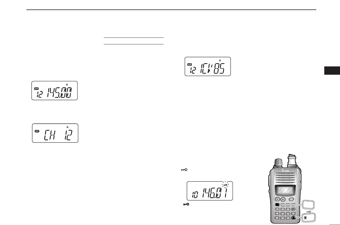
■Display type
The transceiver has 3 display types to suit your operating
style during memory mode operation. The display type is
selected in
INITIAL SET MODE
(p. 53).
“Frequency Indication” type
Displays operating frequency.
“Channel Number Indication” type
Displays memory channel number. In this type only pre-
programmed memory channel numbers are displayed.
VFO mode cannot be selected.
• When the channel indication type is selected, only the following
functions can be performed.
- Scan function (p. 35)
- Output power setting (p. 19)
- DTMF memory function (p. 32)
- Key lock function (see next set of instructions)
- Scan pause timer setting, function key timer setting and LCD
backlight setting in
SET MODE
(p. 49)
“Channel Name Indication” type
Displays memory channel name you have assigned. In this
display pre-programmed memory channel names are dis-
played.
VFO mode is selectable.
• Programmed frequencies are indicated when you have not pre-
programmed the channel names in the selected memory channel.
• Push and hold [MONI] to display the operating frequency.
■Key lock function
The key lock function prevents accidental frequency changes
and function activation.
Push [FUNC] then push and hold
[](✱
ENT
) for 1 sec. to toggle the
function ON and OFF.
•“ ” appears while the lock function is ac-
tivated.
•[PWR], [PTT], [VOL] and [MONI] can be
operated regardless of this setting.
USING
INITIAL SET MODE
DUP SCAN
PRIO
SET
H/M/L
OPT
SKIP
BANK
TONE
T.SCAN
P.BEEP
ABD
C
CALL
ENT
MR CLRFUNC
PWR
9
8
7
4
123
560
A
FUNC
ENT
21
4BASIC OPERATION
DDWeather channel selection
qPush [MR] several times to select weather channel group.
wPush [YY]or [ZZ]several times to select the desired
weather channel.
ePush [MR] to select memory mode, or push [CLR] to se-
lect VFO mode.
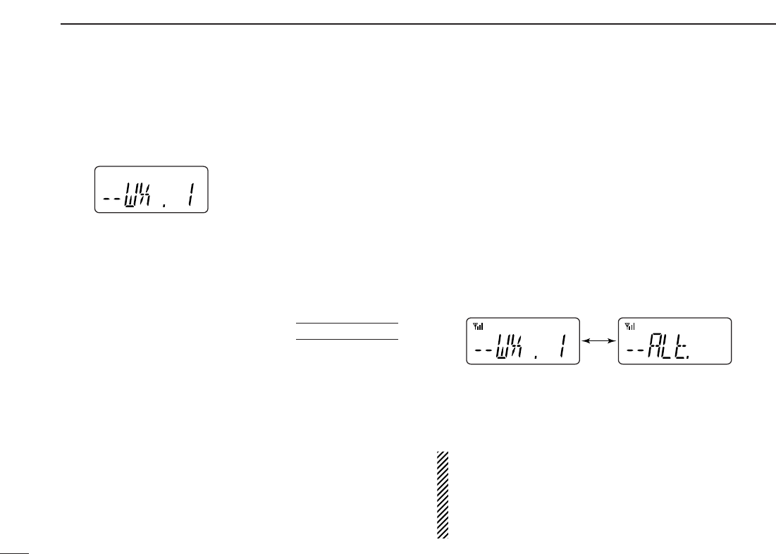
DDWeather alert function
An NOAA broadcast station transmits weather alert tone be-
fore important weather announcements. When the weather
alert function is turned ON, the selected weather channel is
monitored each 5 sec. for the announcement. When the alert
signal is detected, the “ALt” and the WX channel are dis-
played alternately and sounds a beep tone until the trans-
ceiver controls are manipulated. The previously selected
weather channel is checked periodically during standby or
while scanning.
qSelect the desired weather channel.
wTurn the weather alert function ON in
SET MODE
.
➥Push
[FUNC] and
[
SET
](8) to enter
SET MODE
.
➥Push
[YY]
or [ZZ]to select the weather alert item, then
rotate [VOL] to set ON.
➥push [✱
ENT
](or [CLR]) to exit
SET MODE
.
eSelect the desired stand-by condition.
•Select VFO, memory or call channel.
•Scan or priority watch operation can also be selected.
rWhen the alert is detected, a beep sounds and the follow-
ing indication will be displayed.
• Weather alert function OFF
➥ Turn the weather alert function OFF in
SET MODE
.
•Repeat above procedure described at step w
NOTE: While receiving a signal (on a frequency other than
the weather alert ON frequency), the receiving signal or
audio will be interrupted momentarily every 5 sec. (approx.)
in case the alert function is turned ON. This is caused by
the WX alert function. To eliminate the interruptions, set the
weather alert item OFF in
SET MODE
.
Shows above indications alternately.
USING
SET MODE
Weather channel group indication
■Weather channel operation (USA version only)

22
5
REPEATER OPERATION
1
2
3
4
5
6
7
8
9
10
11
12
13
14
15
16
17
18
19
■General
When using a repeater, the transmit frequency is shifted from
the receive frequency by the offset frequency. It is convenient
to program repeater information into memory channels.
qSet the receive frequency (repeater output frequency).
wPush [FUNC] and
[
DUP
](4)
several times to select “–” or “+.”
•“–” indicates the transmit frequency is shifted down; “+” indicates
the transmit frequency is shifted up.
• Blinking “–” or “+” indicates the reversed duplex mode is selected
in
SET MODE
(p. 48).
ePush [FUNC] and [
TONE
](1) several times to activate the
subaudible tone encoder, if required.
•“ ” appears.
•Select the desired subaudible tone frequency, if necessary.
(p. 23)
rPush and hold [PTT] to transmit.
•The displayed frequency automatically changes to the transmit
frequency (repeater input frequency).
•If “OFF” appears, check the offset frequency (see next page for
details) and direction.
tRelease [PTT] to receive.
yPush and hold [MONI] to check whether the other station’s
transmit signal can be directly received.
■Reversed duplex mode
When the reversed duplex mode is selected, the receive fre-
quency shifts. (Transmit frequency shifts in normal duplex mode.)
Each receive and transmit frequency is shown in the table
below with the following conditions;
Input frequency : 145.30 MHz
Direction : – (negative)
Offset frequency : 0.6 MHz
qPush [FUNC], then push [
SET
](8) to enter
SET MODE
.
wPush [YY]or [ZZ]several times until “REV” appears.
eRotate [VOL] to turn the reversed duplex mode ON or
OFF.
rPush [✱
ENT
](or [CLR])to exit
SET MODE
.
USING
SET MODE
Reversed OFF ON
Rx freq. 145.30 MHz 144.70 MHz
Tx freq. 144.70 MHz 145.30 MHz
23
5REPEATER OPERATION
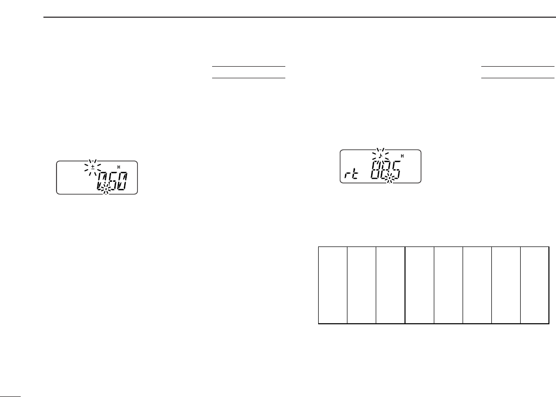
■Offset frequency
When communicating through a repeater, the transmit fre-
quency is shifted from the receive frequency by an amount
determined by the offset frequency.
qPush [FUNC], then push [
SET
](8) to enter
SET MODE
.
wPush [YY]or [ZZ]several times until “±” and offset frequency
appear.
eRotate [VOL] to select the desired offset frequency.
•Selectable steps are the same as the pre-set tuning steps.
•The unit of the displayed offset frequency is “MHz.”
rPush [✱
ENT
](or [CLR]) to set the offset frequency and exit
SET MODE
.
■Subaudible tones
Some repeaters require subaudible tones to be accessed.
Subaudible tones are added to your normal signal and must
be set in advance.
qPush [FUNC], then push [
SET
](8) to enter
SET MODE
.
wPush [YY]or [ZZ]several times until “rt” appears.
eRotate [VOL] to select the desired subaudible tone.
rPush [✱
ENT
](or [CLR]) to set the selected tone and exit
SET MODE
.
• Available subaudible tone frequencies (unit: Hz)
67.0
69.3
71.9
74.4
77.0
85.4
88.5
91.5
94.8
97.4
100.0
103.5
79.7
82.5
107.2
110.9
114.8
118.8
123.0
127.3
131.8
136.5
141.3
146.2
151.4
156.7
159.8
162.2
165.5
167.9
171.3
173.8
177.3
179.9
183.5
186.2
189.9
192.8
196.6
199.5
203.5
206.5
210.7
218.1
225.7
229.1
233.6
241.8
250.3
254.1
USING
SET MODE
USING
SET MODE
24
5
REPEATER OPERATION
1
2
3
4
5
6
7
8
9
10
11
12
13
14
15
16
17
18
19
DDTone information
Some repeaters require different tone system to be accessed.
DTMF TONES
While pushing [PTT], push the desired DTMF keys ([0]–[9],
[A], [B], [C], [D], [#] and [✱]) to transmit DTMF tones.
•[✱]transmits tone “E,” [#] transmits tone “F.”
•The transceiver has 16 DTMF memory channels (p. 32).
1750 Hz TONE
While pushing [PTT], push [YY]or [ZZ]to transmit a 1750 Hz
tone signal.
✔Convenient
Tone scan function: When you don’t know the subaudible
tone used for a repeater, the tone scan is convenient for de-
tecting the tone frequency.
Push [FUNC], then push [
T
.
SCAN
](3) to start the tone scan.
• Push [CLR] to cancel the scan.
• When the required tone frequency is detected, the scan pauses.
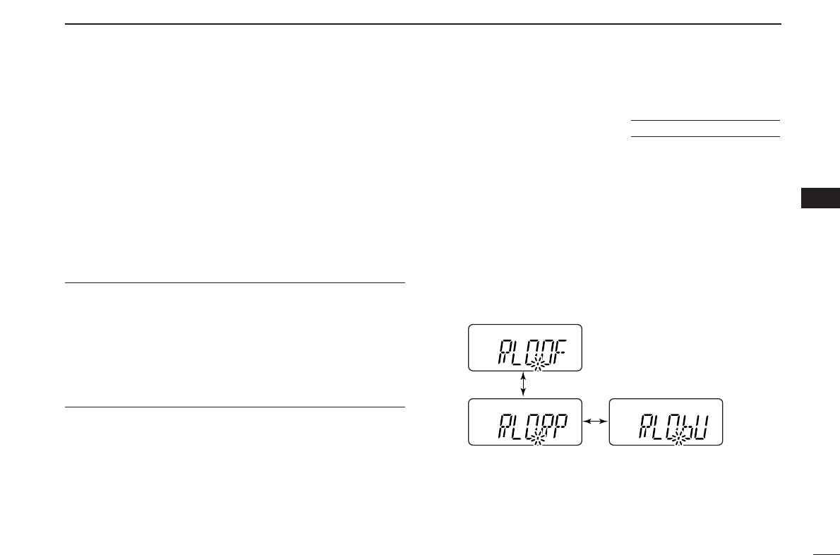
■Repeater lockout
This function helps prevent interference to other stations by
inhibiting your transmission when a signal is received. The
transceiver has two inhibiting conditions, repeater and busy.
qWhile pushing and holding [YY]and [ZZ], turn the power ON
to enter
INITIAL SET MODE
.
wPush [YY]or [ZZ]several times until “RLO” appears.
eRotate [VOL] to select the repeater lockout function to
“RP,” “bU” or OFF.
•“RP”: Transmit is inhibited when a signal with un-matched sub-
audible tone is received.
•“bU”: Transmit is inhibited when a signal is received.
rPush [✱
ENT
](or [CLR]) to exit
INITIAL SET MODE
.
USING
INITIAL SET MODE
25
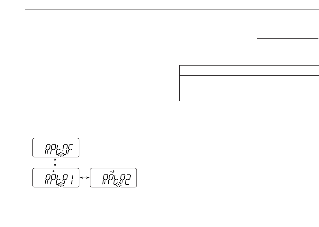
5REPEATER OPERATION
The USA version automatically activates the repeater settings
(duplex ON/OFF, duplex direction, tone encoder ON/OFF)
when the operating frequency falls within or outside of the
general repeater output frequency range. The offset and re-
peater tone frequencies are not changed by the auto repeater
function. Reset these frequencies, if necessary.
qWhile pushing and holding [YY]and [ZZ], turn the power ON
to enter
INITIAL SET MODE
.
wPush [YY]or [ZZ]several times until “RPt” appears.
eRotate [VOL] to select the desired condition.
•“OF”— the auto repeater function is turned OFF;
•“R1”— the auto repeater function activates duplex only;
•“R2”— the auto repeater function activates duplex and tone.
rPush [✱
ENT
](or [CLR]) to exit
INITIAL SET MODE
.
• Frequency range and offset direction
Frequency range Duplex direction
145.200–145.495 MHz “–” appears
146.610–146.995 MHz
147.000–147.395 MHz “+” appears
■Auto repeater function (USA version only)
USING
INITIAL SET MODE
26
6
MEMORY/CALL OPERATION
1
2
3
4
5
6
7
8
9
10
11
12
13
14
15
16
17
18
19
■Selecting a memory channel
qPush [MR] to select memory mode.
•“
X” appears.
wEnter 2 digits to select the desired memory channel (or
push the [YY]/[ZZ]keys).
•The memory channels 0–9 are proceeded by a “0.”
• When [VOL] is assigned as tuning dial, rotate [VOL] to select
the memory channel. (pgs. 18, 53)
■Selecting the call channel
➥Push [CALL] to select the call channel.
•“C” is displayed instead of the memory channel number.
•Push [CLR] or [MR] to select VFO or memory mode, respec-
tively.
Push
CALL
B
“C” appears
Push
(Selection example: Memory channel 14)
DUP
TONE
4
1
Push
MR
C
The transceiver has 107 memory channels including 6 scan
edge memory channels (3 pairs), and 1 call channel. Each
of these channels can be individually programmed with op-
erating frequency (pgs. 17, 18), duplex direction (p. 22) and
offset (p. 23), subaudible tone encoder or tone squelch and
its tone frequency (pgs. 23, 40) and skip information* (p. 37).
*except for scan edge memory channels.
In addition, a total of 10 memory banks, A to J, are available
for usage by group, etc.
■General description
27
6MEMORY/CALL OPERATION
qPush [CLR] to select VFO mode, if necessary.
wSet the desired frequency.
eSet other information, such as tone, duplex, as desired.
rPush [FUNC], then [MR] momentarily.
•“
X” and memory channel number blink.
tPush [YY]or [ZZ]to select the desired memory channel.
• When programming the call channel, select “C.”
• When [VOL] is assigned as tuning dial, rotate [VOL] to select
the memory channel. (pgs. 18, 53)
yPush [FUNC], then push and hold [MR] for 1 sec., when 3
beeps will sound to program the information into the se-
lected memory channel and return to VFO.
•After 3 beeps are emitted, continue to hold [MR] to increment the
displayed memory channel number.
DUP SCAN
PRIO
SET
H/M/L
OPT
SKIP
BANK
TONE
T.SCAN
P.BEEP
ABD
C
CALL
ENT
MR CLRFUNC
PWR
9
8
7
4
123
560
A
FUNC
C
MR
PWR
A
1
4
7
FUNC
TONE
DUP
PRIO
B
2
5
8
CALL
P.BEEP
SCAN
SET
C
3
6
9
SKIP
T.SCAN
MR
H
/
M
/
L
D
0
CLR
BANK
OPT
ENT
DUP SCAN
PRIO
SET
H/M/L
OPT
SKIP
BANK
TONE
T.SCAN
P.BEEP
ABD
C
CALL
ENT
MR CLRFUNC
PWR
9
8
7
4
123
560
A
FUNC
C
MR
■Programming the memory/call channels
28
6
MEMORY/CALL OPERATION
1
2
3
4
5
6
7
8
9
10
11
12
13
14
15
16
17
18
19
■Channel name programming
qSelect a “Channel Name Indication” type in
INITIAL SET
MODE
(p. 53).
wPush [MR] to select memory
mode, if necessary.
ePush [FUNC], then push
[
SET
](8) to enter to the channel
name programming mode.
• The character to be edited blinks.
rRotate [VOL] to select a char-
acter.
tPush [YY]to move the cursor to
right, [ZZ]to move the cursor to
left.
• Up to 5 characters can be used for channel name.
• Usable characters are A–Z, 0–9, “space,” +, –, =, ✱, /, [, ] and :.
yPush [✱
ENT
](or [CLR]) to set the name and exit the chan-
nel name programming mode.
■Memory transfers
This function transfers a memory channel’s contents to VFO
(or another memory/call channel). This is useful when search-
ing for signals around a memory channel frequency and for
recalling the offset frequency, subaudible tone frequency etc.
DMemory/call ➾VFO
qSelect the memory (call) chan-
nel to be transferred:
➥Push [MR] (or [CALL]) to se-
lect memory (call channel)
mode.
➥Push [YY]or [ZZ]to select the
memory channel.
• When [VOL] is assigned as
tuning dial, rotate [VOL] to se-
lect the memory channel. (pgs.
18, 53)
wPush [FUNC], then push and
hold [MR] for 1 sec. to transfer
the selected memory contents
to the VFO.
•VFO mode is selected automatically.
DUP SCAN
PRIO
SET
H/M/L
OPT
SKIP
BANK
TONE
T.SCAN
P.BEEP
ABD
C
CALL
ENT
MR CLRFUNC
PWR
9
8
7
4
123
560
[VOL]
A
FUNC
B
CALL
C
MR
DUP SCAN
PRIO
SET
H/M/L
OPT
SKIP
BANK
TONE
T.SCAN
P.BEEP
ABD
C
CALL
ENT
MR CLRFUNC
PWR
9
8
7
4
123
560
[VOL]
A
FUNC
8
SET
C
MR
ENT
29
6MEMORY/CALL OPERATION
DMemory/call ➾memory/call
qSelect the memory (call) chan-
nel to be transferred:
➥Push [MR] (or [CALL]) to se-
lect the memory (call chan-
nel) mode.
➥Push [YY]or [ZZ]to select the
memory channel.
• When [VOL] is assigned as
tuning dial, rotate [VOL] to se-
lect the memory channel. (pgs.
18, 53)
wPush [FUNC], then push [MR]
momentarily.
•“--” and “X” blink.
ePush [YY]or [ZZ]to select the target memory.
• When [VOL] is assigned as tuning dial, rotate [VOL] to select
the target channel. (pgs. 18, 53)
rPush [FUNC], then push and hold [MR] for 1 sec.
•Memory mode is selected and the contents are transferred to the
target memory.
DClearing a memory
qPush [CLR] to select VFO mode, if necessary.
wPush [FUNC], then push [MR] to enter the memory trans-
fer mode.
•“
X” and a memory channel
number blink.
ePush [YY]or [ZZ]to select the
memory channel to be cleared.
• When [VOL] is assigned as tun-
ing dial, rotate [VOL] to select the
memory channel. (pgs. 18, 53)
•The call channel cannot be
cleared.
rPerform the following operation
within 1 sec, otherwise the
transceiver returns to the mem-
ory mode without clearing the
memory.
- Push [FUNC], then push [MR] momentarily.
- Push [FUNC], then push and hold [MR] for 1 sec.
•The contents of the selected memory are cleared.
tPush [CLR] to return to regular operation.
DUP SCAN
PRIO
SET
H/M/L
OPT
SKIP
BANK
TONE
T.SCAN
P.BEEP
ABD
C
CALL
ENT
MR CLRFUNC
PWR
9
8
7
4
123
560
[VOL]
A
FUNC
B
CALL
C
MR
DUP SCAN
PRIO
SET
H/M/L
OPT
SKIP
BANK
TONE
T.SCAN
P.BEEP
ABD
C
CALL
ENT
MR CLRFUNC
PWR
9
8
7
4
123
560
A
FUNC
C
MR

30
6
MEMORY/CALL OPERATION
1
2
3
4
5
6
7
8
9
10
11
12
13
14
15
16
17
18
19
■Memory bank selection
The IC-V85 has a total of 10 banks (A to J). Each memory
channel, 0 to 99, may be assigned to one of the banks for
easy memory management.
qPush [MR] to select memory mode.
wPush [FUNC] and [
BANK
](#) to
enter memory bank selection.
•Bank indicator blinks.
eRotate [VOL] to select the de-
sired bank, A to J.
•Banks that have no programmed
contents are skipped.
rPush [✱
ENT
](or [CLR]) to select
the bank.
•Indicator stops blinking.
tPush [YY]or [ZZ]to select the channel in the bank.
•No channel numbers are displayed for memory bank operation.
yTo return to regular memory condition, push [FUNC] and
[
BANK
](#) to enter memory bank mode, then push [✱
ENT
]
(or [CLR]).
■Memory bank setting
qPush [MR] to select memory mode, then select the desired
memory channel via [YY]or [ZZ].
wPush [FUNC] and [
SET
](8) to
enter
SET MODE
.
ePush [YY]or [ZZ]several times
until “bAk” appears.
rRotate [VOL] to select the de-
sired bank.
tPush [✱
ENT
](or [CLR]) to assign the channel to the bank
and return to regular memory condition.
yRepeat steps qto tto assign another memory channel
to the same or another bank.
NOTE: Display type setting (pgs. 20, 53) in
INITIAL SET
MODE
must be selected “FR,” otherwise the memory bank
operation cannot be performed.
DUP SCAN
PRIO
SET
H/M/L
OPT
SKIP
BANK
TONE
T.SCAN
P.BEEP
ABD
C
CALL
ENT
MR CLRFUNC
PWR
9
8
7
4
123
560
[VOL]
A
FUNC
8
SET
ENT
Push
MR
C
DUP SCAN
PRIO
SET
H/M/L
OPT
SKIP
BANK
TONE
T.SCAN
P.BEEP
ABD
C
CALL
ENT
MR CLRFUNC
PWR
9
8
7
4
123
560
[VOL]
A
FUNC
BANK
ENT
Push
MR
C
31
6MEMORY/CALL OPERATION
■Transferring bank contents
Contents of programmed memory banks can be cleared or
transferred to another bank.
INFORMATION: Even if the memory bank contents are
cleared, the memory channel contents still remain pro-
grammed.
q
Select the desired bank contents to be transferred or erased.
➥Push [MR] to select memory mode.
➥Push [FUNC] and [
BANK
](#),
then rotate [VOL] to select the
desired memory bank.
•Bank indicator blinks.
➥Push [✱
ENT
](or [CLR]) to se-
lect the bank then push [YY]
and [ZZ]to select the desired
contents.
•Bank indicator stops blinking.
wPush [FUNC] and [
SET
](8) to
enter
SET MODE
.
ePush [YY]or [ZZ]several times
until “bAk” appears.
•Bank indicator appears.
rRotate [VOL] to select the de-
sired bank to receive the trans-
ferred information or erase the
bank contents.
•Select “– –” indication when erasing
the contents from the bank.
tPush [✱
ENT
](or [CLR]) to transfer or erase, and return to
regular memory mode.
yRepeat steps qto tfor transferring or erasing an an-
other bank’s contents.
DUP SCAN
PRIO
SET
H/M/L
OPT
SKIP
BANK
TONE
T.SCAN
P.BEEP
ABD
C
CALL
ENT
MR CLRFUNC
PWR
9
8
7
4
123
560
[VOL]
A
FUNC
8
SET
ENT
DUP SCAN
PRIO
SET
H/M/L
OPT
SKIP
BANK
TONE
T.SCAN
P.BEEP
ABD
C
CALL
ENT
MR CLRFUNC
PWR
9
8
7
4
123
560
[VOL]
A
FUNC
BANK
ENT
32
7
DTMF MEMORY
1
2
3
4
5
6
7
8
9
10
11
12
13
14
15
16
17
18
19
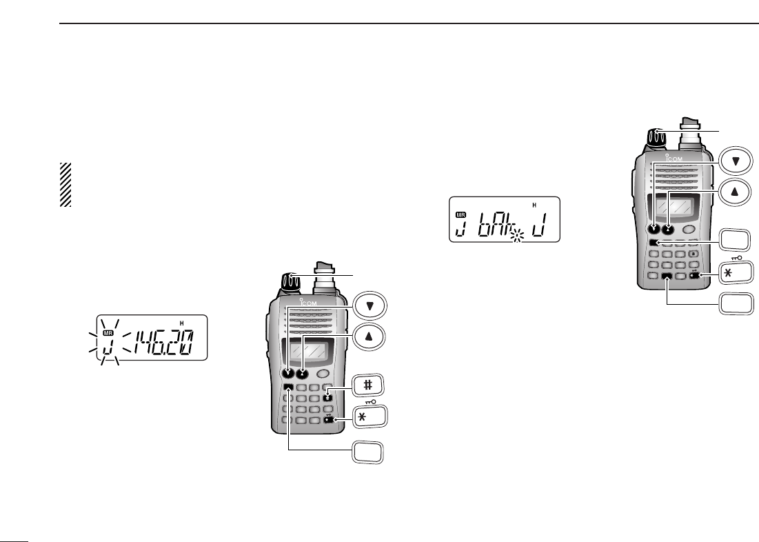
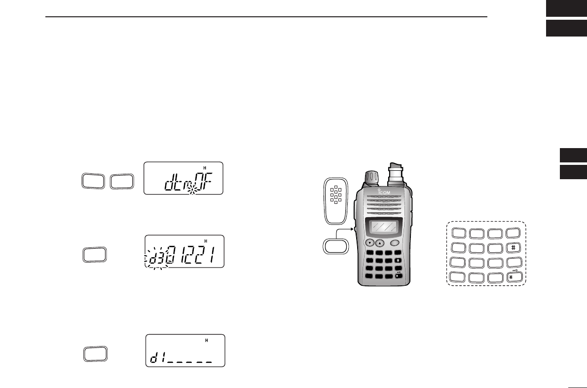
■Programming a DTMF code sequence
The transceiver has 16 DTMF memory channels (d0 to dF)
for storage of often-used DTMF code sequence of up to 24
digits. DTMF memories are used to store phone numbers or
control codes.
qPush [FUNC], then push
[
OPT
](0)
to enter
OPTION SET MODE
.
•Rotate [VOL] to select “dtm.OF,” if necessary.
wPush and hold
[
OPT
](0)
for 1 sec. to select the DTMF mem-
ory.
•One of “d0” to “dF” appears.
e
Rotate [VOL] to select the desired DTMF memory.
rPush and hold [
OPT
](0) for 1 sec. to enter the DTMF pro-
gramming mode.
•“_____” appears.
•Programmed memories can be cleared in this way.
tEnter the desired DTMF code sequence by pushing the
digit keys, [A], [B], [C], [D], [#] and [✱], in the desired
sequence.
•Amaximum of 24 digits can be input.
•[✱]enters tone “E”, [#] enters tone “F.”
•If a digit is mistakenly input, push [MONI] or [PTT] momentarily
then repeat from step q.
yPush [MONI] or [PTT] to save the digits and exit the DTMF
programming mode.
•Programmed DTMF code sequence sounds when [MONI] is
pushed.
•Or after 24th digit is input, the transceiver automatically saves
the digits and returns to step w.
DUP SCAN
PRIO
SET
H/M/L
OPT
SKIP
BANK
TONE
T.SCAN
P.BEEP
ABD
C
CALL
ENT
MR CLRFUNC
PWR
9
8
7
4
123
560
A
1
4
7
FUNC
TONE
DUP
PRIO
B
2
5
8
CALL
P.BEEP
SCAN
SET
C
3
6
9
SKIP
T.SCAN
MR
H
/
M
/
L
D
0
CLR
BANK
OPT
ENT
MONI
Push
OPT
0
for 1 sec.
Push
OPT
0
for 1 sec.
Push
FUNC
A
OPT
0
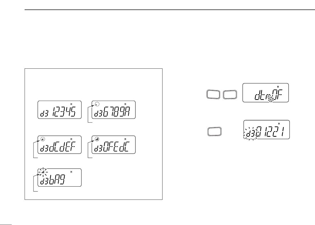
33
7DTMF MEMORY
• DTMF memory indication
■Transmitting a DTMF code
sequence
DUsing a DTMF memory channel
qPush [FUNC], then push
[
OPT
](0)
to enter
OPTION SET MODE
.
•Rotate [VOL] to select “dtm.OF,” if necessary.
wPush and hold
[
OPT
](0)
for 1 sec. to select the DTMF mem-
ory.
eRotate [VOL] to select the desired memory.
rPush [MONI] or [PTT] to exit the DTMF memory mode.
•Selected DTMF code sequence sounds when [MONI] is pushed.
tWhile pushing [PTT], push [MONI] to transmit the selected
DTMF memory.
•After the DTMF code sequence is transmitted, the transceiver re-
turns to receive automatically.
Push
OPT
0
for 1 sec.
Push
FUNC
A
OPT
0
The DTMF memory consists of 5 pages that are 1st to 5th,
6th to 10th, 11th to 15th, 16th to 20th and 21st to 24th dig-
its.
Appears
Blinks
AppearsAppears
• 1st page indication
• 4th page indication
• 5th page indication
• 2nd page indication
• 3rd page indication
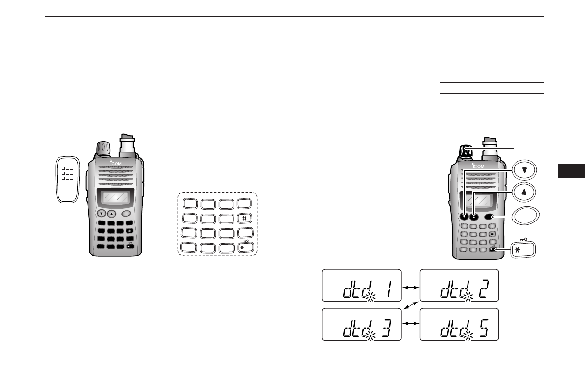
34
7
DTMF MEMORY
1
2
3
4
5
6
7
8
9
10
11
12
13
14
15
16
17
18
19
DManual DTMF code transmission
While pushing [PTT], push digit keys, [A], [B], [C], [D], [#]
and [✱]to transmit a DTMF code sequence manually.
•[✱]transmits tone “E”, [#] transmits tone “F.”
■DTMF transmission rate
When slow DTMF transmission rates are required with DTMF
memory transmission (as for some repeaters), the trans-
ceiver’s rate of DTMF transmission can be adjusted.
qWhile pushing and holding [YY]
and [ZZ], turn the power ON to
enter
INITIAL SET MODE
.
wPush [YY]or [ZZ]several times
until “dtd” appears.
eRotate [VOL] to select the de-
sired DTMF transmission rate.
•Four rates are available: “1” (100
msec. intervals) is the fastest; “5”
(500 msec. intervals) is the slow-
est.
rPush [✱
ENT
](or [CLR]) to exit
INITIAL SET MODE
.
DUP SCAN
PRIO
SET
H/M/L
OPT
SKIP
BANK
TONE
T.SCAN
P.BEEP
ABD
C
CALL
ENT
MR CLRFUNC
PWR
9
8
7
4
123
560
[VOL]
PWR
ENT
USING
INITIAL SET MODE
DUP SCAN
PRIO
SET
H/M/L
OPT
SKIP
BANK
TONE
T.SCAN
P.BEEP
ABD
C
CALL
ENT
MR CLRFUNC
PWR
9
8
7
4
123
560
A
1
4
7
FUNC
TONE
DUP
PRIO
B
2
5
8
CALL
P.BEEP
SCAN
SET
C
3
6
9
SKIP
T.SCAN
MR
H
/
M
/
L
D
0
CLR
BANK
OPT
ENT
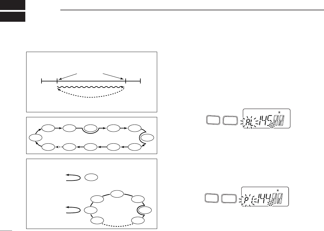
35
SCAN OPERATION
8
■Programmed scan
Programmed scan repeatedly scans between two user pro-
grammed frequencies (memory channels “1A–3A” and
“1b–3b”) or scans between upper and lower band edges. This
scan is useful for checking for signals within a specific fre-
quency range such as repeater output frequencies, etc.
Scans between lower (start) and high (stop) frequency.
qPush [CLR] to select VFO mode, if necessary.
wPush [FUNC] and [
SCAN
](5) to start a scan.
ePush [FUNC] and [
SET
](8) several times to select the de-
sired scan edge, “P1,” “P2,” “P3” or “AL.”
• “AL” for full scan, “P1”, “P2” and “P3” for programmed scan be-
tween the programmed scan edge channels as “1A”–“1b,”
“2A”–“2b” and “3A”–“3b.”
•To change the scan direction, push [YY]or [ZZ].
• When [VOL] is assigned as tuning dial, rotate [VOL] to change
the scan direction. (pgs. 18, 53)
rPush [CLR] to stop the scan.
Push
SET
8
FUNC
A
Push
FUNC
A
SCAN
5
PROGRAMMED SCAN
MEMORY (SKIP) SCAN
PRIORITY WATCH
Band
edge Band
edge
Start
1A
2A
3A
End
1b
2b
3b
Scan edges
Scan
Jump
SKIP SKIP
SKIP
Mch 1
Mch 0
Mch 2 Mch 3
Mch 3
Mch 4 Mch 5
Mch 10
Mch 99
Mch 9 Mch 8 Mch 7
Mch 6
Mch 1
Mch 2
Mch 3
Mch 4
Mch 5
Mch 99
Mch 6
VFO frequency
145.20 MHz
VFO frequency
145.20 MHz
5 sec. 50 msec.
5 sec. 50 msec.
Priority channel
Priority channels
Memory
scan
Priority memory channel watch
Priority memory channel scan
Programmed scan P1 scans between 1A and 1b, P2 scans be-
tween 2A and 2b, and P3 scans between 3A and 3b frequencies.
■Scan types
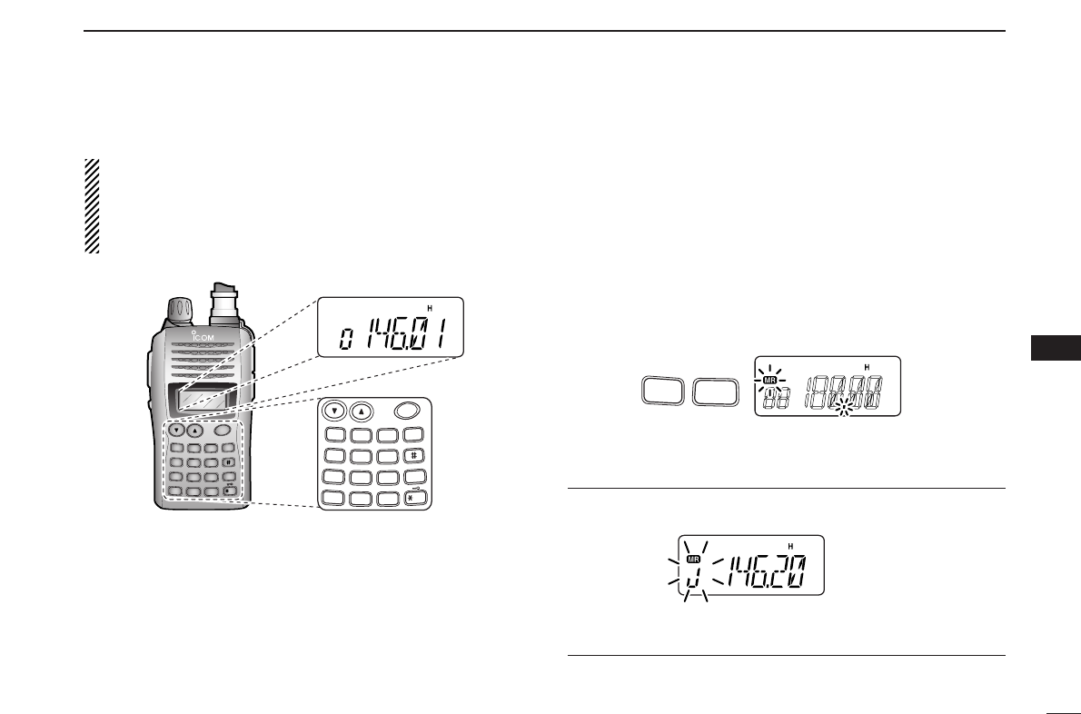
36
8
SCAN OPERATION
1
2
3
4
5
6
7
8
9
10
11
12
13
14
15
16
17
18
19
NOTE: Scan edges, 1A–3A/1b–3b, must be programmed
in advance. Program them in the same manner as regular
memory channels. (p. 27)
If identical frequencies are programmed into the scan
edges, programmed scan will not proceed.
■Memory scan
Memory scan repeatedly scans all programmed memory
channels, except those set as skip channels.
qPush [MR] to select memory mode, if necessary.
•“
X” appears.
•See below to select bank scan.
wPush [FUNC] and [
SCAN
](5) to start the scan.
•To change the scan direction, push [YY]or [ZZ].
• When [VOL] is assigned as tuning dial, rotate [VOL] to change
the scan direction. (pgs. 18, 53)
ePush [CLR] to stop the scan.
• Bank scan —Select the desired bank in step qabove.
qPush [FUNC] and [
BANK
](#) to select memory bank mode.
wRotate [VOL] to select the desired bank, A to J.
ePush [✱
ENT
](or [CLR]) to select the bank.
Push
FUNC
A
SCAN
5
DUP SCAN
PRIO
SET
H/M/L
OPT
SKIP
BANK
TONE
T.SCAN
P.BEEP
ABD
C
CALL
ENT
MR CLRFUNC
PWR
9
8
7
4
123
560
PWR
A
1
4
7
FUNC
TONE
DUP
PRIO
B
2
5
8
CALL
P.BEEP
SCAN
SET
C
3
6
9
SKIP
T.SCAN
MR
H
/
M
/
L
D
0
CLR
BANK
OPT
ENT
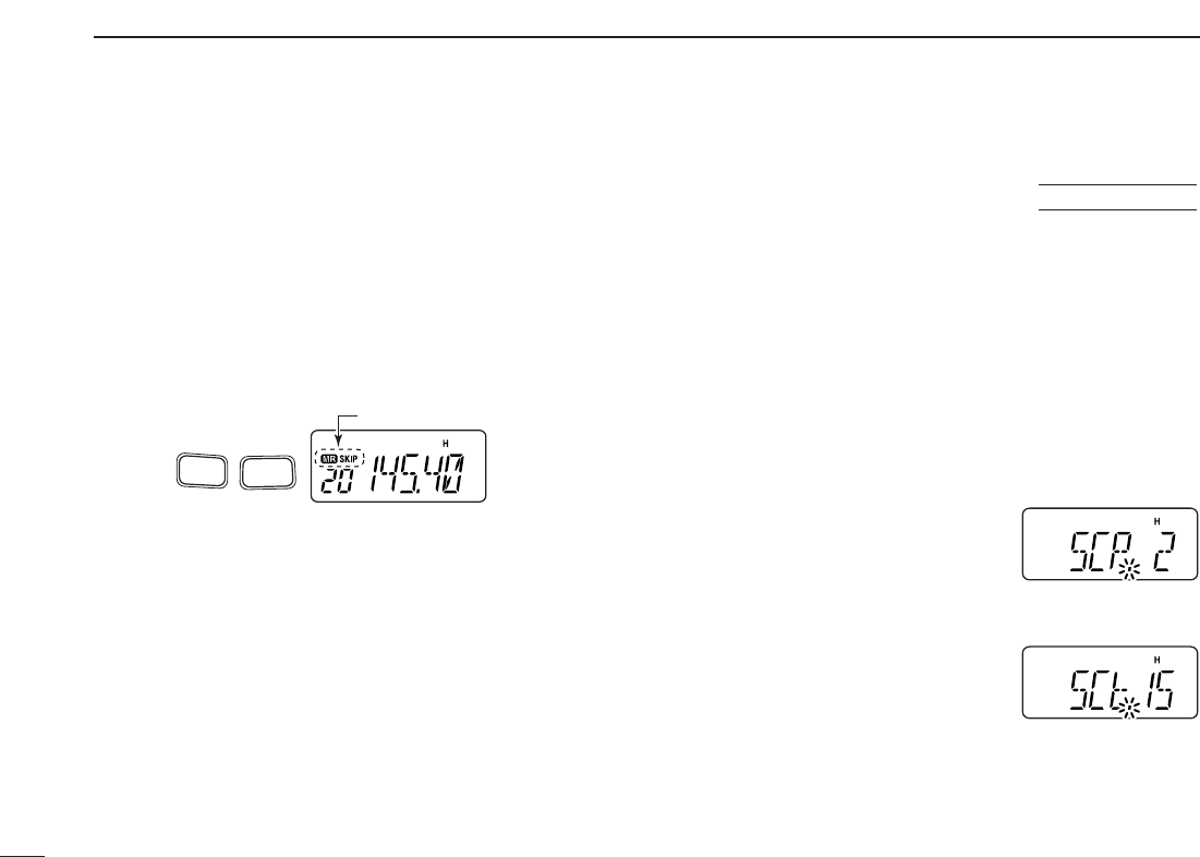
37
8SCAN OPERATION
■Skip channels
In order to speed up the scan rate, you can select memory
channels you don’t wish to scan as skip channels.
qPush [MR] to select memory mode, if necessary.
•“
X” appears.
wSelect a memory channel to set as a skip channel.
ePush [FUNC] and [
SKIP
](6) to toggle the skip setting ON
and OFF.
•“SKIP” appears when the channel is set as a skip channel.
■Scan resume condition
When a signal is received during scanning, the scan resume
condition determines what action the transceiver takes. The
transceiver has 2 scan resume conditions available as
illustrated below. Use
SET MODE
to select the one which best
suits your needs.
qPush [FUNC], then push [
SET
](8) to enter
SET MODE
.
wPush [YY]or [ZZ]several times until “SCP” or “SCt” ap-
pears.
eRotate [VOL] to select the desired scan resume condition.
•Pause scan:
When receiving a signal, scan pauses
on the signal until it disappears. Re-
sumes 2 sec. after the signal disap-
pears.
•Timer scan:
When receiving a signal, scan pauses
on the signal for 5 sec., 10 sec. or 15
sec., then resumes.
rPush [✱
ENT
](or [CLR]) to set and
exit
SET MODE
.
Timer scan
Pause scan
USING
SET MODE
Push
SKIP
FUNC
A
6
“SKIP” appears
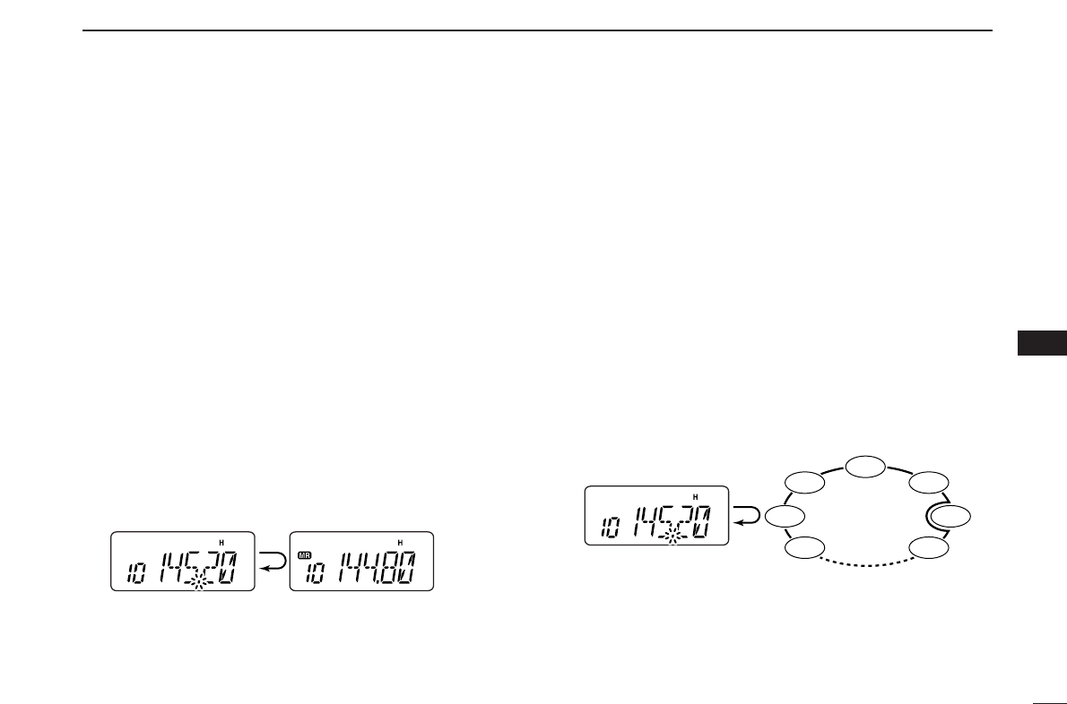
38
8
SCAN OPERATION
1
2
3
4
5
6
7
8
9
10
11
12
13
14
15
16
17
18
19
■Priority watch
Priority watch checks for signals on “priority channels” while
operating on a VFO frequency.
DMemory or call channel watch
While operating on a VFO frequency, memory or call channel
watch monitors for signals in the selected memory or call
channel every 5 sec.
qSelect the desired memory channel or the call channel.
wPush [CLR] to select VFO mode.
ePush [FUNC], then push [
PRIO
](7) to start watching.
•VFO is displayed, then the decimal point “.”, on the frequency
readout blinks.
•The priority channel is monitored every 5 sec.
• When the signal is detected on the priority channel, the watching
is suspended according to the setting of the scan resume condi-
tion.
rPush [CLR] to stop watching.
DMemory scan watch
While operating on a VFO frequency, memory scan watch
monitors for signals in each memory channel in sequence,
every 5 sec.
qPush [MR] to select memory mode, if necessary.
•“X” appears.
wPush [FUNC], then push [
SCAN
](5) to start the memory
scan.
ePush [FUNC], then push [
PRIO
](7) to start the watching.
•VFO is displayed, then the decimal point “.”, on the frequency
readout blinks.
• When the signal is detected on the priority channel, the watching
is suspended according to the setting of the scan resume condi-
tion.
rPush [CLR] to stop the watching.
SKIP
Mch 1
Mch 2
Mch 3
Mch 4
Mch 5
Mch 99
Mch 6
Priority channel
Memory
scan
5 sec.
50 msec.
VFO frequency
5 sec. 50 msec.
VFO frequency Memory channel
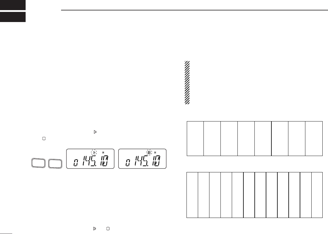
39
SUBAUDIBLE TONES
9
■Tone squelch
DOperation
The tone squelch opens only when receiving a signal con-
taining a matching subaudible tone. You can wait for calls
from group members using the same tone and not hear other
signals.
qSet the operating frequency.
•
Set the volume and squelch to the desired level as the normal op-
eration.
wSet the desired subaudible tone in
SET MODE
.
• See page 40 for programming.
ePush [FUNC], then push [
TONE
](1).
•Repeat several times until “ ” appears when selecting CTCSS,
or “ ” appears when selecting DTCS.
rWhen the received signal includes a matching tone,
squelch opens and the signal can be heard.
• When the received signal’s tone does not match, tone squelch
does not open, however, the S-indicator shows signal strength.
• To open the squelch manually, push and hold [MONI].
tTransmit in the normal way.
yTo cancel the tone squelch, push [FUNC] and [
TONE
](1).
•Repeat several times until “ ” or “ ” disappears.
NOTE: The transceiver has 50 tone frequencies and con-
sequently their spacing is narrow compared to units having
38 tones. Therefore, some tone frequencies may receive
interference from adjacent tone frequencies.
To prevent interference from adjacent tone frequencies,
using the frequencies as in the following table, is recom-
mended.
• Recommended CTCSS frequencies (Unit: Hz)
• Recommended DTCS codes
023
025
026
031
032
043
047
051
054
065
071
072
073
074
114
115
116
125
131
132
134
143
152
155
156
162
165
172
174
205
223
226
243
244
245
251
261
263
265
271
306
311
315
331
343
346
351
364
365
371
411
412
413
423
431
432
445
464
465
466
503
506
516
532
546
565
606
612
624
627
631
632
654
662
664
703
712
723
731
732
734
743
754
67.0
69.3
71.9
74.4
77.0
79.7
82.5
85.4
88.5
91.5
94.8
97.4
100.0
103.5
107.2
110.9
114.8
118.8
123.0
127.3
131.8
136.5
141.3
146.2
151.4
156.7
162.2
167.9
173.8
179.9
186.2
192.8
203.5
210.7
218.1
225.7
233.6
241.8
250.3
D
Push
TONE
1
FUNC
A
CTCSS DTCS
D
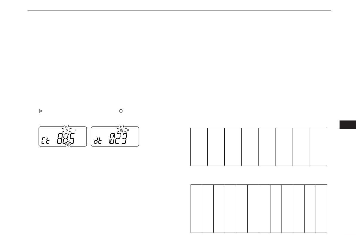
40
9
SUB AUDIBLE TONES
1
2
3
4
5
6
7
8
9
10
11
12
13
14
15
16
17
18
19
Separate tone frequencies can be select for tone squelch op-
eration rather than repeater operation (the same range of
tones is available— see right below). Like the repeater tones,
these are set in
SET MODE
.
qSelect VFO or memory channel.
wPush [FUNC], then push [
SET
](8) to enter
SET MODE
.
ePush [YY]or [ZZ]several times until “Ct” appears when se-
lecting CTCSS, or “dt” appears when selecting DTCS.
•“ ” blinks when selecting CTCSS, or “ ” blinks when selecting
DTCS.
rRotate [VOL] to select the desired subaudible tone.
tPush [✱
ENT
](or [CLR]) to program the selected tone and
exit
SET MODE
.
•The recommended CTCSS frequencies or DTCS codes are
shown at previous page.
When
SET MODE
is selected from memory mode.
The tone squelch frequency is not stored in the selected
memory channel unless you follow steps yand u.
yPush [FUNC], then push and hold [MR] for 1 sec. to trans-
fer the contents to VFO.
•3 beeps are emitted.
•VFO mode is selected automatically.
uPush [FUNC], then push and hold [MR] for 1 sec.
•3 beeps are emitted.
•Available CTCSS tone frequency (unit: Hz)
•Available DTCS codes
023
025
026
031
032
036
043
047
051
116
122
125
131
132
134
143
145
152
225
226
243
244
245
246
251
252
255
371
411
412
413
423
431
432
445
446
516
523
526
532
546
565
606
612
624
053
054
065
071
072
073
074
114
115
155
156
162
165
172
174
205
212
223
325
331
332
343
346
351
356
364
365
452
454
455
462
464
465
466
503
506
627
631
632
654
662
664
703
712
723
731
732
734
743
754
261
263
265
266
271
274
306
311
315
67.0
69.3
71.9
74.4
77.0
79.7
82.5
85.4
88.5
91.5
94.8
97.4
100.0
103.5
107.2
110.9
114.8
118.8
123.0
127.3
131.8
136.5
141.3
146.2
151.4
156.7
159.8
162.2
165.5
167.9
171.3
173.8
177.3
179.9
183.5
186.2
189.9
192.8
196.6
199.5
203.5
206.5
210.7
218.1
225.7
229.1
233.6
241.8
250.3
254.1
CTCSS DTCS
D
DSetting subaudible tones for tone squelch operation
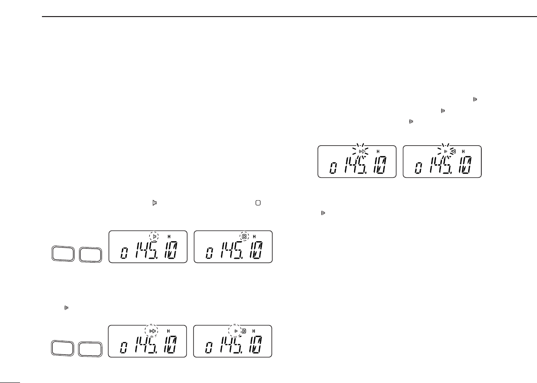
41
9SUBAUDIBLE TONES
■Pocket beep operation
This function listens for subaudible tones and can be used as
a “common pager” to inform you that someone has called
when you were away from the transceiver.
DWaiting for a call from a specific station
qSet the operating frequency.
wSet the desired CTCSS tone frequency or DTCS code in
SET MODE
.
• See p. 40 for programming details.
ePush [FUNC], then push [
TONE
](1).
•Repeat several times until “ ” appears when CTCSS, or “ ” ap-
pears when DTCS is selected.
rPush [FUNC], then push [
P
.
BEEP
](2) to activate the pocket
beep function.
•“” appears.
tWhen a signal with the matching tone is received, the
transceiver emits beep tones and blinks “ .”
• Beep tones sound for 30 sec. and “ ” blinks. To stop the beeps
manually, push any key. “ ” continues blinking until step yis
operated.
yPush [PTT] to answer.
• “ ” disappears and cancels the pocket beep function automati-
cally.
CTCSS DTCS
Push
P.BEEP
2
FUNC
A
CTCSS DTCS
Push
TONE
1
FUNC
A
CTCSS DTCS
D
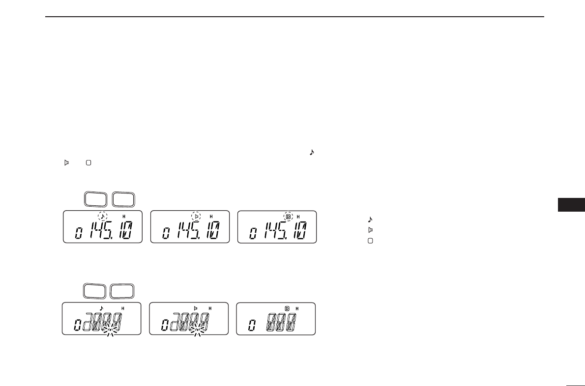
42
9
SUB AUDIBLE TONES
1
2
3
4
5
6
7
8
9
10
11
12
13
14
15
16
17
18
19
■Tone scan
By monitoring a signal on a repeater, or using pocket beep or tone
squelch function, you can determine the tone frequency necessary to
access a repeater or open the squelch.
qSet the frequency to be checked for a tone frequency or code.
wPush [FUNC], then push [
TONE
](1).
•Repeat several times to select the type of tone to be scanned. (One of “ ,”
“” or “ ” appears)
•Tone scan may be used even if the tone condition or type is not selected.
ePush [FUNC], then push [
T
.
SCAN
](3) to start the tone scan.
• To change the scanning direction, push [YY]or [ZZ].
Push
T.SCAN
3
FUNC
A
Push
TONE
1
FUNC
A
D
rWhen the CTCSS tone frequency or DTCS code
is matched, the squelch opens and the tone fre-
quency or code is temporarily programmed into
the selected mode such as memory or call chan-
nel.
•The tone scan pauses when a CTCSS tone fre-
quency or 3-digit DTCS code is detected.
•The decoded CTCSS tone frequency or 3-digit DTCS
code is used for the tone encoder or tone encoder/de-
coder depending on the selected tone condition or
type in step w.
-No indication : Cannot be used for operation.
-“ ” : CTCSS tone encoder
-“ ” : CTCSS tone encoder/decoder
-“ ” : DTCS tone encoder/decoder
tPush [CLR] to stop the scan.
D
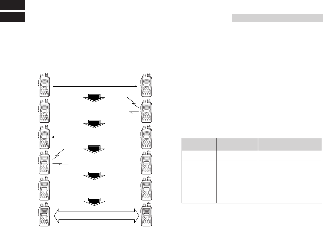
43
PAGER/CODE SQUELCH
10
■Pager function
This function uses DTMF codes for paging and can be used
as a “message pager” to confirm you of a caller’s identification
even when you leave the transceiver temporarily unattended.
■
Code programming
DDBefore programming
The pager and code squelch functions require ID codes and a
group code. These codes are 3-digit DTMF codes and must
be written into the code channels before operation.
qDecide the ID code of each transceiver and a group code
for your group.
wDecide whether you want to return to normal operation or
code squelch operation after a connection is made.
eProgram the ID code, group code and transmit codes
(other station’s codes) as below.
DDCode channel assignment
*
Channel CP automatically memorizes an ID code when receiving a
pager call. The contents in channel CP cannot be changed manually.
Pager selective code (push [PTT])
Beep Beep
Beep
Answer back (manual)
Beep Beep
Beep
Set both transceivers to either
code squelch or non-coded operation
Communication
ID OR CODE CHANNEL “RECEIVE ACCEPT” OR
GROUP CODE NUMBER “RECEIVE INHIBIT”
Your ID code
Other parties’
ID code
Group code
Memory space*
0
1–6
One of 1–6
P
“Receive accept” only
“Receive inhibit” should be
programmed in each channel.
“Receive accept” must be
programmed in one channel.
“Receive inhibit” only.
Requires Optional UT-108
Optional UT-108 is required when using the pager/code squelch functions.
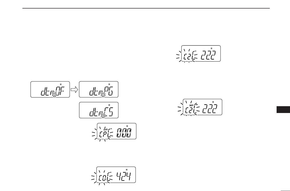
44
10
PAGER/CODE SQUELCH
1
2
3
4
5
6
7
8
9
10
11
12
13
14
15
16
17
18
19
DDCode programming
Your ID code MUST be programmed into code channel C0.
Up to 6 transmit codes (codes that you transmit) are pro-
grammable into code channels, C1 to C6, if required.
qPush [FUNC], then push [
OPT
](0) to enter
OPTION SET
MODE
.
•Rotate [VOL] to select “dtm.PG” or “dtm.CS,” if “dtm.OF” ap-
pears.
wPush and hold [
OPT
](0) for 1
sec. to enter the code selection
mode.
•One of either “CP” or “C0” to “C6”
blinks.
•“C0” is your ID code and “C1” to “C6” are transmit codes.
eRotate [VOL] (or push [YY]/[ZZ]) to select code channel C0.
•Each transceiver should have a different ID code.
rEnter the desired 3-digit ID
code via the keypad.
tRotate [VOL] (or push
[YY]/[ZZ]) to select a transmit
code channel from C1 to C6.
yEnter the desired 3-digit transmit code via the keypad.
uPush [FUNC], then push [
SKIP
](6) to set the channel to “re-
ceive inhibit” or “receive accept.”
•When “receive inhibit” is set, “SKIP” appears as below.
•Code channel C0 cannot be set as “receive inhibit.”
•See the table for “receive accept” and “receive inhibit” details
(p. 43).
iRepeat steps tand yto set additional transmit code
channels, if desired.
oPush [✱
ENT
](or [CLR]) to exit code selection mode.
•Receive accept/receive inhibit
➥“Receive accept” (“SKIP” indicator does not appear) ac-
cepts pager calls when the transceiver receives a signal
with a code the same as that in the code channel.
➥“Receive inhibit” (“SKIP” indicator appears) ignores calls
even when the transceiver receives a code the same as
that in the code channel. Transmit codes should therefore
be programmed for “receive inhibit,” otherwise the trans-
ceiver will not reject unnecessary calls.
or
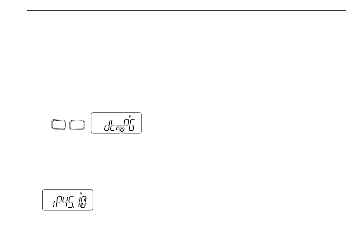
45
10 PAGER/CODE SQUELCH
■Pager operation
DCalling a specific station
qProgram the code channel in advance (p. 44).
wSet the operating frequency.
•
Set the volume and squelch to the desired level as in normal op-
eration.
ePush [FUNC], then push [
OPT
](0).
•Rotate [VOL] to select “dtm.PG,” if “dtm.CS” or “dtm.OF” ap-
pears.
rSelect the desired transmit code channel:
➥Push and hold [
OPT
](0) for 1 sec. to enter the code se-
lection mode.
➥Rotate [VOL] (or push [YY]/[ZZ]) to select the desired
code channel.
➥Push [✱
ENT
](or [CLR]) to return to previous mode.
•100 MHz digit shows “P.”
tPush [PTT] to transmit the pager code.
yWait for an answer back.
•When the transceiver receives an answer back code, the func-
tion display shows the other member’s ID or group code.
uAfter confirming a connection, push [FUNC] and [
OPT
](0)
to enter
OPTION SET MODE
, then rotate [VOL] to select the
code squelch operation “dtm.CS,” or non-selective calling
system “dtm.OF.”
•DO NOT push any digit keys while code channels C0 to C6 are
displayed, otherwise code channel contents will be changed.
iCommunicate with the other party as normal: push [PTT]
to transmit; release to receive.
DWaiting for a call from a specific station
qSet the operating frequency.
wPush [FUNC], then push [
OPT
](0).
➥Rotate [VOL] to select “dtm.PG,” if “dtm.CS” or
“dtm.OF” appears.
➥Push [✱
ENT
](or [CLR]) to return to previous mode.
•100 MHz digit shows “P.”
eWait for a call.
•When receiving a call, the caller’s ID or group code appears as
shown at next page.
•DO NOT push any digit keys while code channels C0 to C6 are
displayed, otherwise code channel contents will be changed.
rPush [PTT] to send an answer back call and display the
operating frequency.
tAfter confirming a connection, push [FUNC] and [
OPT
](0)
to enter
OPTION SET MODE
, then rotate [VOL] to select the
code squelch operation “dtm.CS,” or non-selective calling
system “dtm.OF.”
Push
FUNC
A
OPT
0
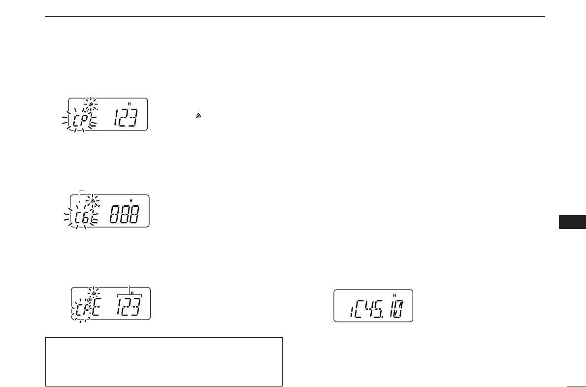
46
10
PAGER/CODE SQUELCH
1
2
3
4
5
6
7
8
9
10
11
12
13
14
15
16
17
18
19
•PERSONAL CALLS
This display appears when you are called with your ID code
and the calling station’s ID code is 123.
•GROUP CALLS
This display appears when you are called with the group
code, 888, and 888 has been programmed into code channel
C6.
•ERROR INFORMATION
When the transceiver receives an incomplete code, “E” and
previously received code appear.
■Code squelch
When using code squelch you will only receive calls from sta-
tions which know your ID or group code. A 3-digit code is sent
each time [PTT] is pushed in order to open the receiving sta-
tion’s code squelch prior to voice transmission.
qSet the operating frequency.
• Set the volume and squelch to the desired level as in normal op-
eration.
wPush [FUNC], then push [
OPT
](0).
• Rotate [VOL] to select “dtm.CS,” if “dtm.PG” or “dtm.OF” ap-
pears.
eSelect the desired transmit code channel:
➥Push and hold [
OPT
](0) for 1 sec. to enter code selec-
tion mode.
➥Rotate [VOL] (or push [YY]/[ZZ]) to select the desired
code channel.
➥Push[✱
ENT
](or [CLR]) to exit code selection mode and
return to previous mode.
•100 MHz digit shows “C.”
rOperate the transceiver in the normal way (push [PTT] to
transmit; release [PTT] to receive).
tTo cancel the code squelch, push [FUNC] and [
OPT
](0),
then rotate [VOL] to select “dtm.OF.”
•100 MHz digit shows “1” when the function is cancelled.
Previously received code.
Code channel
“CP” and “ ” blink.
During channel number indication (described on page 20)
To use these functions in channel number indication, the
pager/code squelch setting must be programmed with other
memory contents before selecting channel number indication.
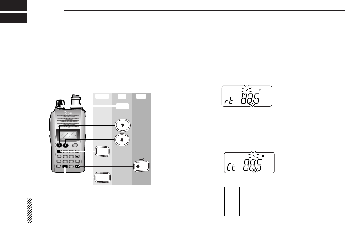
47
SET MODES
11
■SET MODE
DDEntering SET MODE
qPush [FUNC], then push [
SET
](8) to enter
SET MODE
.
wPush [YY]or [ZZ]to select the desired item.
eRotate [VOL] to select the condition/value.
•To exit
SET MODE
, push [✱
ENT
](or [CLR]).
NOTE: When the display type setting (pgs. 16, 65) in
INI
-
TIAL SET MODE
is selected other than “FR” (“CH” or “nm”)
and accessing
SET MODE
from memory mode, most of set
mode items are restricted.
DDRepeater tone frequency
Selects tone encoder frequency for accessing a repeater, etc.
from one of 50 available frequencies.
•67.0–254.1 Hz (50 tones): 88.5 Hz (default)
DDTone squelch frequency
Selects frequency for tone squelch or pocket beep operation
from one of 50 available frequencies.
•67.0–254.1 Hz (50 tones): 88.5 Hz (default)
•Available subaudible tone frequencies
67.0
69.3
71.9
74.4
77.0
79.7
82.5
85.4
88.5
91.5
94.8
97.4
100.0
103.5
107.2
110.9
114.8
118.8
123.0
127.3
131.8
136.5
141.3
146.2
151.4
156.7
159.8
162.2
165.5
167.9
171.3
173.8
177.3
179.9
183.5
186.2
189.9
192.8
196.6
199.5
203.5
206.5
210.7
218.1
225.7
229.1
233.6
241.8
250.3
254.1
DUP SCAN
PRIO
SET
H/M/L
OPT
SKIP
BANK
TONE
T.SCAN
P.BEEP
ABD
C
CALL
ENT
MR CLRFUNC
PWR
9
8
7
4
123
560
Enter ExitSet
[VOL]
A
FUNC
8
SET
ENT
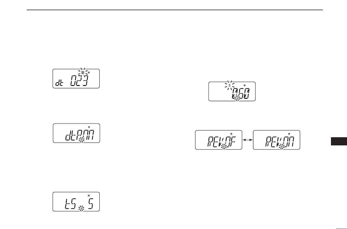
48
11
SET MODES
1
2
3
4
5
6
7
8
9
10
11
12
13
14
15
16
17
18
19
DDDTCS code
Selects DTCS (both encoder/decoder code) for DTCS
squelch operation. Total of 104 codes are available.
•023–754: 023 (default)
DDDTCS polarity
Selects DTCS polarities for transmission and reception from
“nn (default),” “nR,” “Rn” and “RR.” (n: normal/R: reverse)
DDTuning step
Selects tuning step from 5, 10, 12.5, 15, 20, 25, 30 and
50 kHz for [YY]/[ZZ]or [VOL] (When [VOL] is assigned as tuning
dial) operation. (default value may differ depending on trans-
ceiver types and versions)
DDOffset frequency
Sets the duplex offset frequency within 0 to 20 MHz range.
During duplex (repeater) operation, transmit frequency (or re-
ceive when reverse function is set to ON) shifts the set fre-
quency. (default value may differ depending on transceiver
types and versions)
DDReverse function
Turns the reverse function ON and OFF (default).
Reverse function OFF Reverse function ON

49
11 SET MODES
DDScan pause timer
Selects the scan pause time from SCt.5, SCt.10, SCt.15 and
SCP. 2. When receiving signals, the scan pauses according
to the scan pause time.
•SCt. 5/10/15 : Scan pauses for 5/10/15 sec.
(default: SCt.15)
•SCP. 2 : Scan pauses until the signal disappears. Re-
sumes 2 sec. after the signal disappears.
DDFunction key timer
Selects the function indicator display timer (when pushed
[FUNC]) from F0.At, F1.At, F2.At, F3.At and F .m.
•F0.At : “ ” disappears immediately after secondary func-
tion is operated. (default)
•F1/2/3.At: “ ” disappears after 1/2/3 sec. after secondary
function is operated.
•F .m : “ ” appears until [FUNC] is pushed again.
DDLCD backlight
Selects LCD backlight lighting condition from auto, ON and
OFF.
•LIG.At : Lights when any key except [PTT] is pushed. (de-
fault)
•LIG.ON: Lights continuously while the transceiver is pow-
ered ON.
•LIG.OF : Never lights.
DDTransmission permission
Turns transmission permission ON and OFF. This function
can be set for each memory and call channel, independently.
•tX .On : Transmission is permitted. (default)
•tX .OF : Transmission is inhibited.
F
F
F
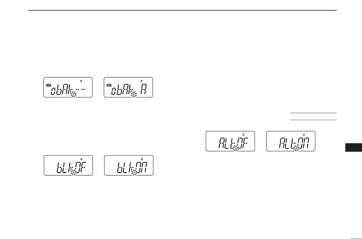
50
11
SET MODES
1
2
3
4
5
6
7
8
9
10
11
12
13
14
15
16
17
18
19
DDMemory bank setting
Sets the desired memory bank (A to J and OFF) to assign the
regular memory channels.
This item appears when
SET MODE
is accessed from memory
mode only.
DDMemory bank link function
Sets the memory bank link function ON and OFF (default).
The link function provides continuous banks scan, scanning
all contents in the selected banks during bank scan.
This item appears when
SET MODE
is accessed from memory
mode only.
•Bank link setting
qRotate [VOL] to select the memory bank link function ON.
wPush [YY]or [ZZ]to select the desired bank to be linked.
•bLA: Bank A, bLb: Bank B, bLC: Bank C, bLd: Bank D,
bLE: Bank E, bLF: Bank F, bLG: Bank G, bLH: Bank H,
bLI: Bank I, bLJ: Bank J
eRotate [VOL] to “ON” to link the bank.
rRepeat steps wand eto link other banks.
DDWeather alert function
Turns weather alert function ON and OFF (default).
USA version only
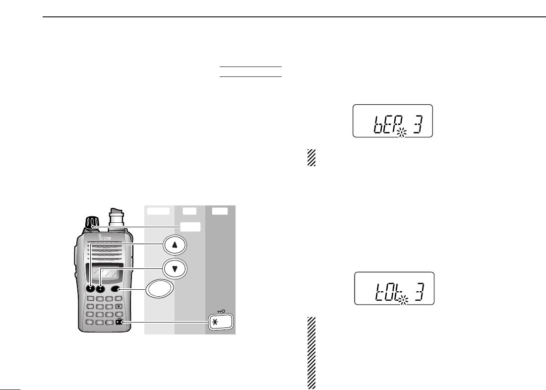
51
11 SET MODES
■INITIAL SET MODE
The
INITIAL SET MODE
is accessed at power on and allows you
to set seldom-changed settings. In this way, you can “cus-
tomize” transceiver operations to suit your preference and op-
erating style.
DDEntering INITIAL SET MODE
qWhile pushing and holding [YY]and [ZZ], turn power ON.
wPush [YY]or [ZZ]to select the desired item.
eRotate [VOL] to select the condition or value.
•To exit
INITIAL SET MODE
, push [✱
ENT
](or [CLR]).
DDKey-touch beep
Turns key-touch beep emission ON (Beep level 1 to 3) or
OFF. (default: 3)
NOTE: The pocket beep level (Beep level 1 to 3 or OFF)
also changes as this setting.
DDTime-out timer
To prevent accidental prolonged transmission, etc., the trans-
ceiver has a time-out timer. This function cuts a transmission
OFF after 1–30 min. of continuous transmission. This timer
can be cancelled.
•tOt.OF : The time-out timer is turned OFF.
•tOt. 1–30: The transmission is cut OFF after the set period
elapses. (default: 3)
• BE CAREFUL! The transceiver will become hot when
this time-out timer function is turned OFF and transmis-
sion is made for long periods.
• NOTE: When the battery pack (BP-227) becomes hot
from continuous transmittion, etc., the battery’s protection
circuit may activate to protect the battery itself and then
shut off the transceiver power until it has cooled down.
DUP SCAN
PRIO
SET
H/M/L
OPT
SKIP
BANK
TONE
T.SCAN
P.BEEP
ABD
C
CALL
ENT
MR CLRFUNC
PWR
9
8
7
4
123
560
Enter ExitSet
[VOL]
PWR
ENT
AT
POWER ON
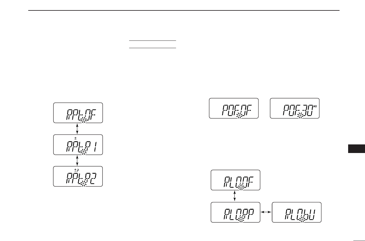
52
11
SET MODES
1
2
3
4
5
6
7
8
9
10
11
12
13
14
15
16
17
18
19
DDAuto repeater
The auto repeater function automatically turns ON or OFF the
duplex operation and tone encoder. The offset and repeater
tone is not changed by the auto repeater function. Reset
these frequencies, if necessary.
•RPt.OF : The auto repeater function is turned OFF.
•RPt.R1 : Activates for duplex only. (default)
•RPt.R2 : Activates for duplex and tone.
DDAuto power-off
The transceiver can be set to automatically turn OFF after a
specified period with a beep when no key operations are per-
formed.
•30min., 1 hour, 2 hours and OFF (default) can be specified.
The specified period is retained even when the transceiver
is turned OFF by the auto power-off function. To cancel the
function, select “
POF.OF” in this
SET MODE
.
DDRepeater lock-out
Selects lockout type from repeater, busy and OFF.
•RLO.OF : No lockout is activated. (default)
•RLO.RP : The repeater lockout is turned ON.
•RLO.bU : The busy lockout is turned ON.
USA version only
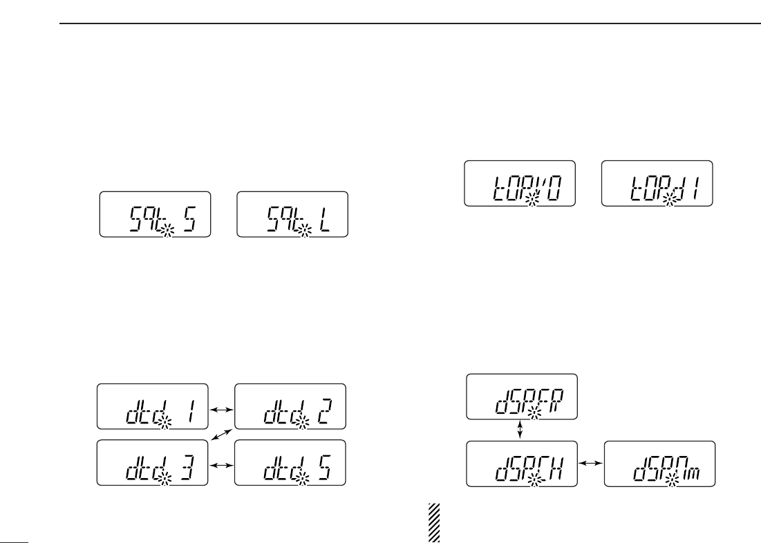
53
11 SET MODES
DDSquelch delay
Selects squelch delay from short and long to prevent re-
peated opening and closing of the squelch during reception
of the same signal.
•Sqt. S : The squelch closes in short delay. (default)
•Sqt. L : The squelch closes in long delay.
DDDTMF rate
The rate at which DTMF memories send individual DTMF
characters can be set to accommodate operating needs.
•1: 100 msec. interval; 5.0 cps rate (default)
•2: 200 msec. interval; 2.5 cps rate
•3: 300 msec. interval; 1.6 cps rate
•5: 500 msec. interval; 1.0 cps rate (cps=characters/sec.)
DDDial assignment
Selects [VOL] control action from volume and tuning dial.
•tOP.VO: AF volume (default)
•tOP.dI : Tuning dial
DDDisplay type
Selects LCD indication type from frequency, channel number
and channel names.
•dSP.FR : Shows frequency (default)
•dSP.CH : Shows channel number*
•dSP.nm : Shows channel names†
*Only memory channels can be selected.
† Frequency indication will be displayed when the selected memory
channel has no programmed memory name.
NOTE: When this setting is selected other than “FR” (“CH”
or “nm”) and accessing
SET MODE
from memory mode,
most of set mode items are restricted.
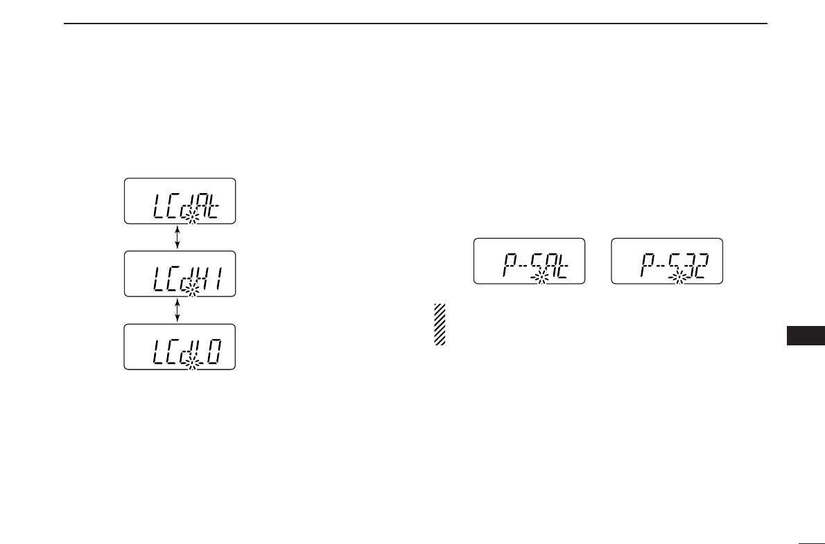
54
11
SET MODES
1
2
3
4
5
6
7
8
9
10
11
12
13
14
15
16
17
18
19
DDLCD contrast
Selects LCD contrast from auto, high and low.
•LCd.At : Automatic (default)
•LCd.HI : High contrast
•LCd.LO : Low contrast
DDPower save
Selects duty cycle for power save function from auto, 1:32,
1:16, 1:8, 1:2 and OFF.
•P–S.At : Duty cycle changes automatically. (default)
•P–S.32 : 1:32 duty cycle
•P–S.16 : 1:16 duty cycle
•P–S. 8 :
1:8 duty cycle
•P–S. 2 :
1:2 duty cycle
•P–S.OF : The power save function is turned OFF.
NOTE: During pager or code squelch operation (with UT-
108), the active duty cycle is fixed 1:1 only (even for duty
cycle settings other than OFF).
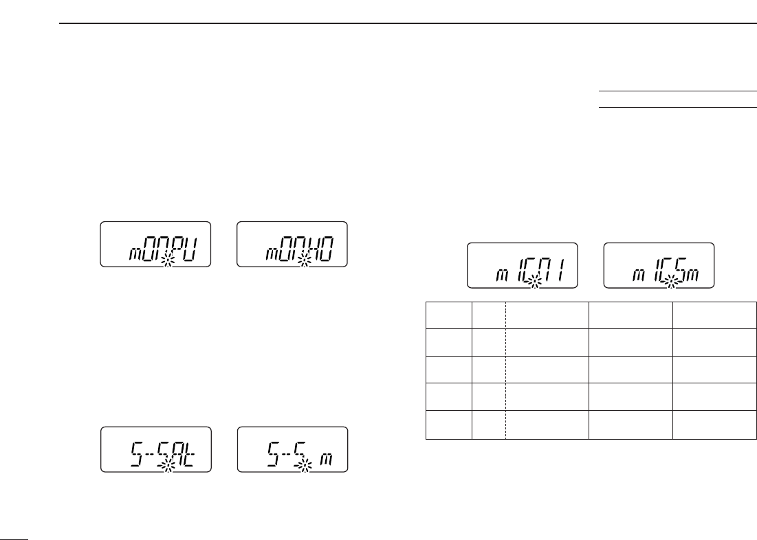
55
11 SET MODES
DDMonitor key action
The monitor key, [MONI], can be set as a ‘sticky’ key. When
set to the sticky condition, each push of [MONI] toggles the
monitor function ON and OFF.
•PU (Push) : Pushing and holding [MONI] to monitor the fre-
quency. (default)
•HO (Hold) : Push [MONI] to monitor the frequency and push
again to cancel it.
DDTuning speed acceleration
The tuning speed acceleration automatically speeds up the
tuning speed when pushing and holding [YY]or [ZZ], or rotat-
ing [VOL] rapidly.*
•S–S.At : The tuning speed acceleration is activated. (de-
fault)
•S–S. m : The tuning speed acceleration is not activated.
*When tuning dial is assigned with [VOL].
DDMic simple mode
This item turns the microphone simple mode ON and OFF.
Microphone simple mode is used to change the function as-
signments for keys in the optional HM-75A
REMOTE CONTROL
SPEAKER
-
MICROPHONE
as below. This assignment is conve-
nient for 3-channel use of simple operation.
•mIC.n1 : Normal 1 (default)
•mIC.n2 : Normal 2
•mIC.Sm: Simple mode
A1750 Hz tone can be transmitted with the HM-75A opera-
tion.
➥Push [A] while pushing [PTT].
Optional HM-75A required
HM-75A Mode NORMAL1 NORMAL2 SIMPLE
key
[A] Freq. [CALL] [MONI] [MONI]
CH Null
[B] Freq. VFO/Memory VFO/Memory [CALL]
CH Null Null
[YY]Freq. Freq. Up Freq. Up MR-00CH
CH Memory CH Up Memory CH Up
[ZZ]Freq. Freq. Down Freq. Down MR-01CH
CH Memory CH Down Memory CH Down

56
11
SET MODES
1
2
3
4
5
6
7
8
9
10
11
12
13
14
15
16
17
18
19
NOTE:
Turn power OFF when connecting the HM-75A to the
transceiver.
VFO mode cannot be selected via the microphone when
SIMPLE mode is selected.
DDBattery protection function
Sets the Battery protection function from LI (Li-Ion) (default)
and OFF.
LI(Li-Ion):
➥The transceiver does not memorized the transceiver
ON/OFF condition when battery is detached, and automat-
ically returns to OFF condition even if you detach the bat-
tery with the transceiver ON condition. You are required to
turn ON the transceiver by pushing [PWR] for every bat-
tery attach.
➥Beep sounds when the attached battery is exhaustion.
•The battery must be charged presently.
OFF : The transceiver memorizes the transceiver ON/OFF
condition when battery is detached.
NOTE: This item MUST be set “LI” (Li-Ion) when the at-
taching battery is BP-227 (Li-Ion).
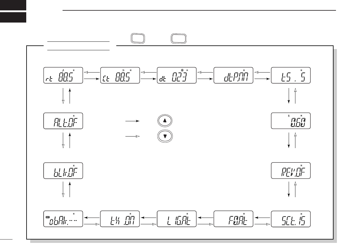
57
SET MODE INSPECTION
12
SET MODE
• Weather alert* (p. 50)
• Repeater tone
frequency (p. 47) • Tone squelch
frequency (p. 47) • DTCS code (p. 48) • DTCS polarity (p. 48)
• Offset frequency (p. 48)
• Reverse function
(p. 48)
• Tuning step (p. 48)
• Scan pause timer
(p. 49)
• Function key timer
(p. 49)
• LCD backlight
(p. 49)
• Tx permission
(p. 49)
• Bank link function†
(p. 50)
• Bank setting†
(p. 50)
*Available for [USA] version only.
†Appears when accessing SET MODE from memory mode only.
: Push
: Push
Push , then push to enter SET MODE (p. 47).
A
FUNC
8
SET
NOTE: When the display type setting (pgs. 20, 53) in INITIAL
SET MODE is selected other than “FR” (“CH” or “nm”) and
accessing SET MODE from memory mode, most of set mode
items are restricted.
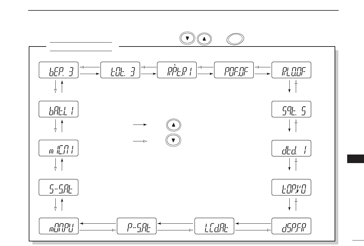
58
12
SET MODE INSPECTION
1
2
3
4
5
6
7
8
9
10
11
12
13
14
15
16
17
18
19
INITIAL SET MODE
• Battery protection function (p. 56)
• Mic simple mode (p. 55)
• Key touch beep (p. 51) • Time-out timer (p. 51) • Auto repeater* (p. 52) • Auto power-off (p. 52)
• Squelch delay (p. 53)
• DTMF rate (p. 53)
• Repeater lock-out (p. 52)
• Dial assignment (p. 53)
• Display type (p. 53)• LCD contrast (p. 54)• Power save (p. 54)
• Tuning speed acceleration (p. 55)
• Monitor key action (p. 55)
*Available for [USA] version only.
: Push
: Push
While pushing and holding , push to enter INITIAL SET MODE (p. 51).
PWR
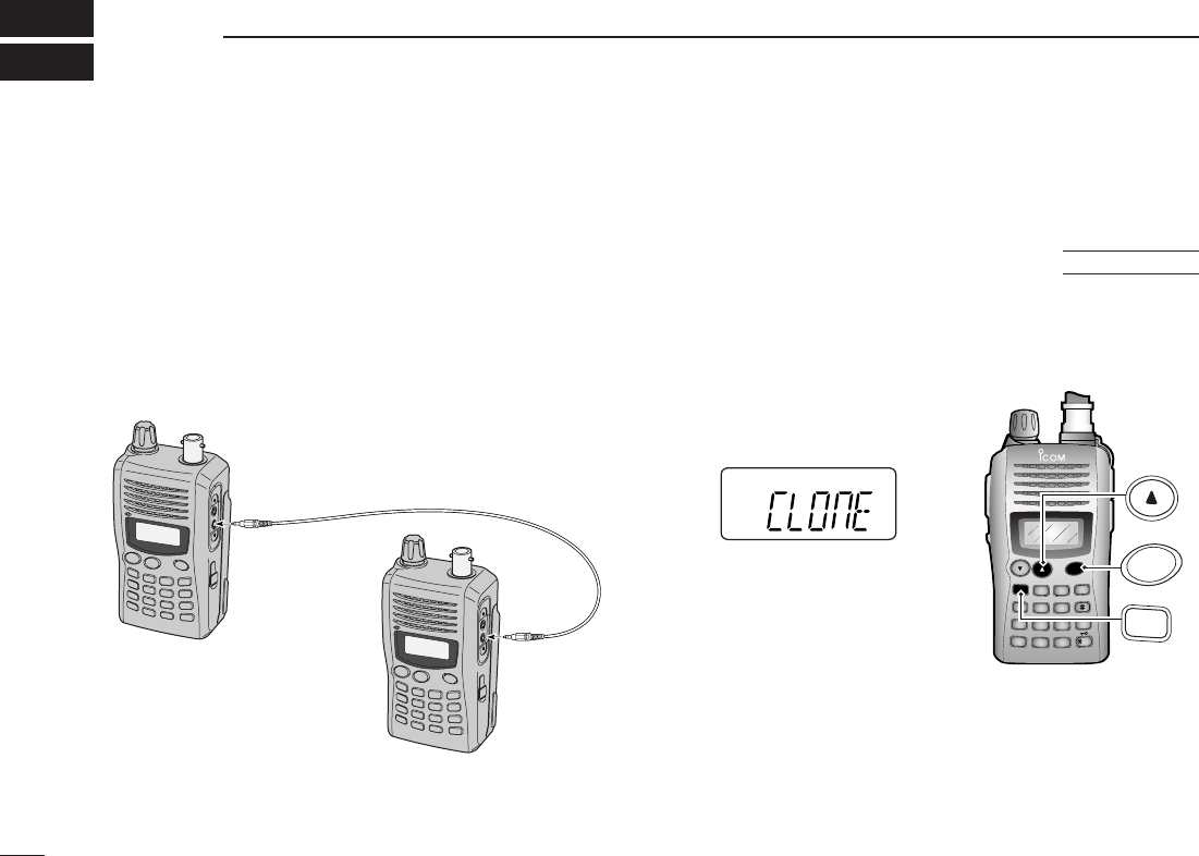
59
CLONING
13
qConnect the OPC-474
CLONING CABLE
to the [SP] jack of
the master and sub-transceivers.
•The master transceiver is used to send data to the sub-trans-
ceiver.
wWhile pushing [FUNC] and [YY], turn power ON to enter
cloning mode (master transceiver only— power ON for
sub-transceiver).
•“CLONE” appears and the
transceivers enter the clone
standby condition.
DUP SCAN
PRIO
SET
H/M/L
OPT
SKIP
BANK
TONE
T.SCAN
P.BEEP
ABD
C
CALL
ENT
MR CLRFUNC
PWR
9
8
7
4
123
560
A
FUNC
PWR
Master transceiver
Sub transceiver
Cloning allows you to quickly and easily transfer the pro-
grammed contents from one transceiver to another trans-
ceiver.
■Transceiver-to-transceiver cloning
AT
POWER ON
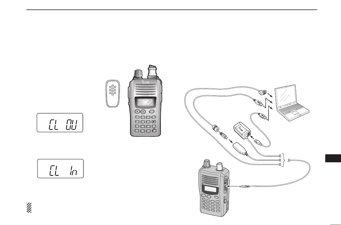
60
13
CLONING
1
2
3
4
5
6
7
8
9
10
11
12
13
14
15
16
17
18
19
Please refer to the HELP file that comes with CS-V85
CLONING SOFTWARE
.
■Cloning using a PC
PC
TRANSCEIVER
to USB port
to USB port
to RS-232C port
OPC-478
(RS-232C type)
OPC-478U
(USB type)
OPC-478UC
(USB type)
ePush [PTT] on the master
transceiver.
•“CL OU” appears in the master
transceiver’s display and S-
meter indicator shows that
data is being transferred to
the sub-transceiver.
•“CL In” appears automatically in the sub-transceiver’s display and
S-meter indicator shows that data is being received from the
master transceiver.
rWhen cloning is finished, turn power OFF, then ON again
to exit cloning mode.
NOTE: DO NOT push [PTT] on the sub-transceiver during
cloning. This will cause a cloning error.
DUP SCAN
PRIO
SET
H/M/L
OPT
SKIP
BANK
TONE
T.SCAN
P.BEEP
ABD
C
CALL
ENT
MR CLRFUNC
PWR
9
8
7
4
123
560

61
RESETTING FUNCTIONS
14
■Partial reset
If you want to initialize the operating conditions (VFO fre-
quency, VFO settings, set mode contents) without clearing
the memory contents, a partial resetting function is available
for the transceiver.
➥While pushing [CLR], push and hold [PWR] for 1 sec. to
partially reset.
■CPU reset
The function display may occasionally display erroneous in-
formation (e.g. when first applying power). This may be
caused externally by static electricity or by other factors.
If this problem occurs, turn power OFF. After waiting a few
seconds, turn power ON again. If the problem persists, per-
form the following procedure.
•Partial resetting is also available. See left for details.
IMPORTANT!:
Resetting the transceiver CLEARS all memory information
and initializes all values in the transceiver.
➥While pushing [MONI] and [CLR], push and hold [PWR]
for 1 sec. to reset the CPU.
•“CLEAR” indicates, then initial display appears.
DUP SCAN
PRIO
SET
H/M/L
OPT
SKIP
BANK
TONE
T.SCAN
P.BEEP
ABD
C
CALL
ENT
MR CLRFUNC
PWR
9
8
7
4
123
560
CLR
D
MONI
PWR
AT
POWER ON
DUP SCAN
PRIO
SET
H/M/L
OPT
SKIP
BANK
TONE
T.SCAN
P.BEEP
ABD
C
CALL
ENT
MR CLRFUNC
PWR
9
8
7
4
123
560
CLR
D
PWR
AT
POWER ON

62
15
TROUBLESHOOTING
1
2
3
4
5
6
7
8
9
10
11
12
13
14
15
16
17
18
19
PROBLEM
No power comes ON.
No sound comes from the
speaker.
Transmitting is impossible.
No contact possible with
another station.
Frequency can not be set.
Program scan function
can not start.
Memory scan function can
not start.
The displayed frequency is
erroneous.
Can not charge the battery
with BC-167A/D.
If your transceiver seems to be malfunctioning, please check the following points before sending it to a service center.
POSSIBLE CAUSE
• The batteries are exhausted.
• The battery polarity is reversed.
• The BP-227 becomes hot.
(Battery’s protection circuit may activate.)
• Volume level is too low.
• Different tone is selected with tone/DTCS
squelch.
• The batteries are exhausted.
• Different tone is selected with tone/DTCS
squelch.
• The key lock function is activated.
• Memory mode or call channel is selected.
• Memory mode or call channel is selected.
• Same frequencies are programmed both “✱A”
and “✱b” of scan edge memory channel.
• VFO mode or call channel is selected.
• The programmed memory channel is only
one.
• The CPU malfunctioned.
• External factors caused a fault.
• Turn the transceiver’s power ON.
SOLUTION
• Replace the batteries or charge the battery pack.
• Check the battery polarity.
• Cool down the BP-227.
• Rotate [VOL] to suitable level.
• Check the tone using tone/DTCS scan.
• Replace the batteries or charge the battery pack.
• Check the tone/DTCS using tone scan.
• Push [FUNC] then push and hold []
(✱
ENT
)
for 1 sec. to cancel the function.
• Push [CLR] to set VFO mode.
• Push [CLR] to set VFO mode.
• Programming different frequencies in “✱A” and
“✱b” respectively.
• Push [MR] to set memory mode.
• Program more than 2 memory channels.
• Reset the transceiver.
• Remove and re-attach the battery pack or battery
case.
• Turn the transceiver’s power OFF, then connect
the BC-167A/D to charge.
REF.
pgs. 9, 13–15
p. 10
–
p. 19
p. 42
pgs. 9, 13–15
p. 42
p. 20
p. 17
p. 17
p. 27
p. 26
p. 27
p. 61
p. 9
pgs. 13 ,17
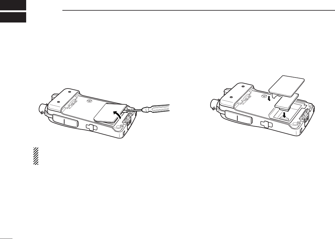
63
OPTION
16
■Optional UT-108 installation
qRemove the optional connector access cover
(named 2251
OPT sheet)
.
•Insert a screwdriver into the hollow of the chassis, then lift and
take away the cover. (The removed cover cannot be used
again.).
WARNING!
NEVER attempt to remove the optional connector cover
using your finger nails, this may result in injury.
wAttach the optional unit. Insert the connector firmly to avoid
a bad contact.
•Remove the paper baking of the optional unit before installing.
eRemove the paper backing of 2251 OPT sheet supplied as
an accessory.
rAttach the new 2251 OPT sheet to the service window.
tProgram the necessary information from the transceivers
keypad or using the cloning software, before operation.
r
ew
q

64
17
SPECIFICATIONS
1
2
3
4
5
6
7
8
9
10
11
12
13
14
15
16
17
18
19
■General
•Frequency coverage : (unit: MHz)
USA Tx: 144–148/Rx: 136–174*1
Europe, UK Tx: 144–146/Rx: 136–174*2
Taiwan, Thailand, Korea Tx/Rx: 144–146
General (LM) Tx/Rx: 136–174*1
*1: Guaranteed: 144–148 MHz range only
*2: Guaranteed: 144–146 MHz range only
•Type of emission : FM
•Number of memory channels : 107 (incl. 6 scan edges and 1 call)
•Frequency resolution : 5, 10, 12.5, 15, 20, 25, 30, 50 kHz
•Operating temperature range : –10°C to +60°C; +14˚F to +140˚F
•Frequency stability : ±2.5 ppm
(–10°C to +60°C; +14˚F to +140˚F)
•Power supply requirement :
Supplied (or optional) Icom’s battery
pack or 11.0 V±15% external DC power
•Current drain : (at 7.2 V DC: approx.)
Transmit at 7 W (High) 2.6 A
at 4 W (Middle) 2.0 A
at 0.5 W (Low) 1.0 A
Receive standby 80 mA
power save 30 mA
max. audio 250 mA
•Antenna connector : BNC (50 Ω)
•Dimensions (proj. not included) :56(W) ×110(H) ×34.4(D) mm
27⁄32(W)×411⁄32(H)×111⁄32(D) in
(with BP-227)
•Weight (approx.) : 310 g; 12.5 oz
(with BP-227 and Ant.)
165 g; 5.8 oz
(without battery pack and Ant.)
■Transmitter
•Modulation system : Variable reactance frequency mod.
•Output power (at 7.2 V) :
[Thailand] 5.5 W/4 W/0.5 W (High/Mid/Low)
[Others] 7 W/4 W/0.5 W (High/Mid/Low)
•Max. frequency deviation : ±5.0 kHz
•Spurious emissions : Less than –60 dBc
•Microphone connector :
3-conductor 2.5 (d) mm (
1
⁄
10
″)/2.2 kΩ
■Receiver
•Receive system : Double-conversion superheterodyne
•Intermediate frequencies : 1st: 46.35 MHz, 2nd: 450 kHz
•Sensitivity (at 12 dB SINAD) :Less than 0.2 µV
•Squelch sensitivity (threshold) :Less than 0.16 µV
•Selectivity : More than 55 dB
•Spurious and image rejection : More than 60 dB
•Intermodulation : More than 55 dB
•
Audio output power
:More than 0.3 W at 10% distortion with
(at 7.2 V DC)
an 8 Ωload
•Ext. speaker connector : 3-conductor 3.5 (d) mm (1⁄8″)/8 Ω
All stated specifications are subject to change without notice or obligation.

65
CE
18
Versions of the IC-V85E which display the
“CE” symbol on the serial number seal,
comply with the essential requirements of
the European Radio and Telecommunica-
tion Terminal Directive 1999/5/EC.
This warning symbol indicates that this
equipment operates in non-harmonised fre-
quency bands and/or may be subject to li-
censing conditions in the country of use.
Be sure to check that you have the correct
version of this radio or the correct pro-
gramming of this radio, to comply with na-
tional licensing requirement.
ABOUT CE
•When transmitting with a portable radio, hold the radio in a
vertical position with its microphone 2.5 to 5 centimeters
away from your mouth. Keep antenna at least 2.5 centime-
ters from your head and body.
•If you wear a potable two-way radio on your body, ensure
that the antenna is at least 2.5 centimeters from your body
when transmitting.
INSTALLATION NOTES

66
18
CE
1
2
3
4
5
6
7
8
9
10
11
12
13
14
15
16
17
18
19
DECLARATION
OF CONFORMITY
Kind of equipment: FM TRANSCEIVER
Type-designation: iV85E
Version (where applicable):
This compliance is based on conformity with the following harmonised
standards, specifications or documents:
i) EN 301 489-1 v 1.4.1 (2002-08)
ii) EN 301 489-15 v 1.2.1 (2002-08)
iii) EN 301 783 v 1.1.1 (2000-09)
iv) EN 60950-1 (2001): A11: 2004
Place and date of issue
Icom (Europe) GmbH
Himmelgeister straße 100
Authorized representative name
H.
IKegami
General Manager
Signature
Declare on our sole responsibility that this equipment complies with the
essential requirements of the Radio and Telecommunications Terminal
Equipment Directive, 1995/5/EC, and that any applicable Essential Test
Suite measurements have been performed.
We Icom Inc. Japan
1-1-32, Kamiminami, Hirano-ku
Osaka 547-0003, Japan
16th Nov. 2006
D-40225
DOC

1-1-32 Kamiminami, Hirano-ku, Osaka 547-0003, Japan
A-6552D-1EX
Printed in Japan
©2006 Icom Inc.
<Intended Country of Use>
■GER ■FRA ■ESP ■SWE
■AUT ■NED ■POR ■DEN
■■GBR ■BEL ■ITA ■FIN
■IRL ■LUX ■■GRE ■■SUI
■■NOR
#02 Europe
#22 Europe-1
<Intended Country of Use>
■■GER ■■FRA ■■ESP ■■SWE
■■AUT ■■NED ■■POR ■■DEN
■GBR ■■BEL ■■ITA ■■FIN
■■IRL ■■LUX ■■GRE ■■SUI
■■NOR
#23 UK