ICOM orporated 297400 VHF Air Band Transceiver User Manual IC A210
ICOM Incorporated VHF Air Band Transceiver IC A210
UserManual.wiki
>
ICOM orporated
>
297400 User Manual
>
Manual Revised
Contents
1.
Manual Revised
2.
User Manual
Manual Revised
Navigation menu
Upload a User Manual
Namespaces
Wiki Guide
HTML
PDF
Info
Views
User Manual
Discussion / Help
Navigation
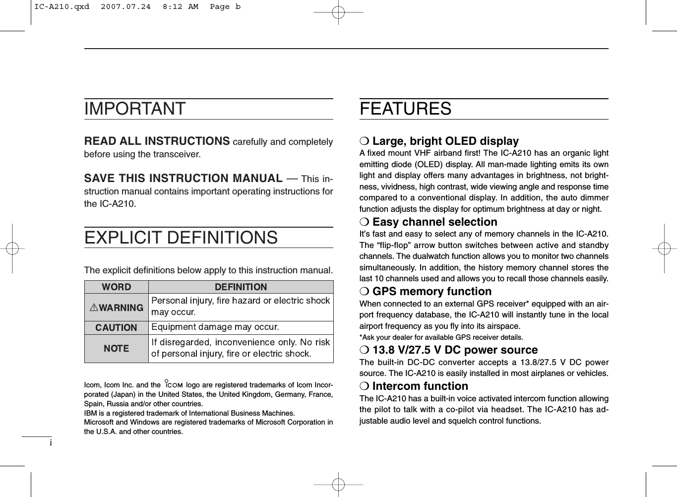
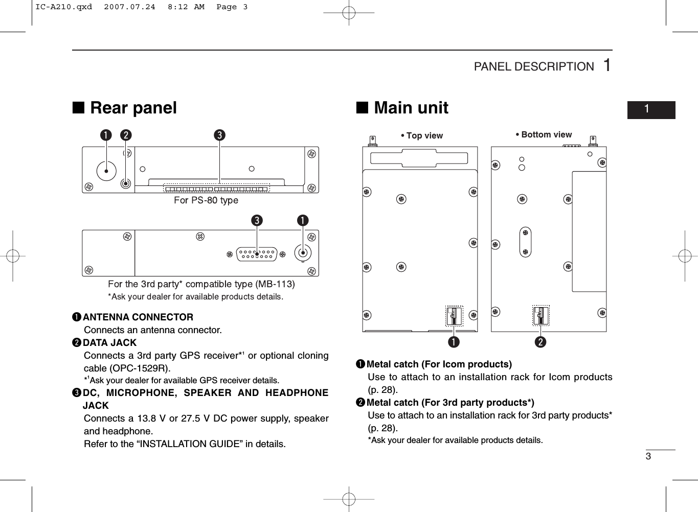
![11PANEL DESCRIPTION01■Front panelqDUAL SWITCH [DUAL]➥Push to turn dualwatch operation ON or OFF (p. 8).➥Push and hold for 2 sec. to turn the intercom functionON or OFF.wEMERGENCY CHANNEL SWITCH [EC]➥Push to set the emergency frequency (121.5 MHz) tothe standby frequency (p. 19).➥Push and hold for 2 sec. to enter the direct frequencysetting mode (p. 8), and set the emergency frequency(121.5 MHz) (p. 19).eVOLUME/POWER SWITCH [VOL]➥Turn [VOL] to switch the power ON and OFF (p. 5).➥Adjusts the audio output level.The volume level bar appears while rotating [VOL].➥Push to set the squelch test function ON or OFF (p. 20).➥Push and hold for 2 sec. to start the weather channel(U.S.A. version only) scan (p. 21).rFREQUENCY EXCHANGE SWITCH (FLIP-FLOP)[↔]➥Push to exchange the standby frequency with the ac-tive frequency (p. 6).➥Push and hold for 2 sec. to enter direct frequency set-ting mode (p. 8).RCLMEMOFFVOLPUSHTESTCOMMDUALECiA210CH09 SAMPLE121.525118.00RX MEMORYeytriouqwIC-A210.qxd 2007.07.24 8:12 AM Page 1](https://usermanual.wiki/ICOM-orporated/297400.Manual-Revised/User-Guide-820686-Page-5.png)
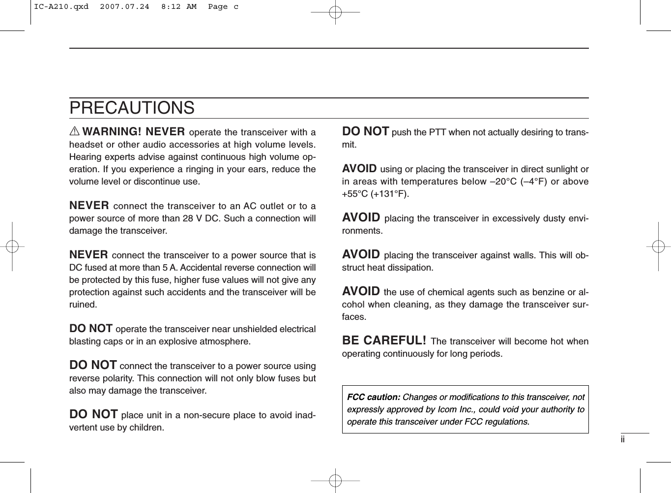
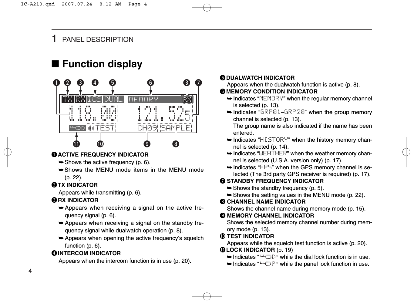
![21PANEL DESCRIPTION■Front panel (Continued)tMEMORY SWITCH [MEM]➥Push and hold for 2 sec. to be programmed a displayedfrequency to any blank regular memory channel ordelete/revive the selected memory channel (dependingon the operating mode) (p. 9).➥Push to display the memory mode menu, and operateselected menu (p. 9).yRECALL SWITCH [RCL]➥Push to enter/exit the memory mode (p. 9).➥Push and hold for 2 sec. to enter the menu mode(p. 22).uLIGHT-SENSITIVE DETECTORThis detector senses ambient light. The detector is usedto adjust “Dimmer brightness (Low/High)” (p. 25) automat-ically when “Dimmer Mode” (p. 25) sets to ‘AUTO.’iINNER (Small) TUNING DIAL [DIAL]➥Rotate to set the standby frequencies (kHz digit) (p. 5),memory channels (p. 10), MENU mode conditions(p. 22), etc.➥Push and hold for 2 sec. to turn the dial/panel lock func-tion ON (p. 19).oOUTER (Large) TUNING DIAL [O-DIAL]➥Rotate to set the standby frequencies (MHz digit) (p. 5),group memory channel (p. 13), cursor position (p. 15),etc.➥Rotate to change the scan direction while scanning(p. 21).RCLMEMOFFVOLPUSHTESTCOMMDUALECiA210CH09 SAMPLE121.525118.00RX MEMORYeytriouqwIC-A210.qxd 2007.07.24 8:12 AM Page 2](https://usermanual.wiki/ICOM-orporated/297400.Manual-Revised/User-Guide-820686-Page-6.png)
![52BASIC OPERATION0102■Frequency selectionIC-A210 has 2 ways to select the desired frequency.ïGeneral frequency selectionSelect the desired frequency which is used for the next oper-ating frequency in the standby frequency indicator. Then ex-change the active frequency for the standby frequency.NOTE: Operate from “Standby frequency selection(Step 1-2)” to “Frequency exchanging (Step 2-2)” as pgs. 5–6.ïDirect frequency selectionThe desired frequency direct selection is available.Refer to “Direct frequency selection mode operation.”■Standby frequency selection(Step 1-2)qRotate [VOL] clockwise to turn power ON.• Previously used frequencies appear in the active andstandby frequency indicators.wRotate [DIAL] and [O-DIAL] to select the desired fre-quency to the standby frequency.• The active frequency is not affected.• Rotate [O-DIAL] to set above 1 MHz digit.• Rotate [DIAL] to set below 100 kHz digit.•Set the frequency step* in the menu mode, if necessary (p. 27).*Available for depending on versions.TIP: For quick frequency setting, often used frequenciescan be programmed into memory channels. Refer to “MEM-ORY OPERATION” (pgs. 9–18).When a memory channel is recalled, the previous standbyfrequency is erased.CAUTION: DO NOT turn the power ON until the aircraft engines havebeen started. It is very important for protection of the powersupply circuit.IC-A210.qxd 2007.07.24 8:12 AM Page 5](https://usermanual.wiki/ICOM-orporated/297400.Manual-Revised/User-Guide-820686-Page-9.png)
![62BASIC OPERATION■Frequency exchanging/not exchanging (Step 2-2)qAfter selecting the standby frequency, push [↔]to ex-change the standby frequency with the active frequency.•Rotate [VOL] to set the volume level, if necessary.• When receiving a signal, “RX” appears and audio is emitted fromthe speaker or headset.•Further adjustment of audio level may be necessary at this point.• Adjust the squelch level in the menu mode, if necessary (p. 24).wPush and hold [PTT] to transmit, then speak into the mi-crophone.• Transmit indicator “TX” lights.eRelease [PTT] to receive.Frequency exchanging can be also performed remotely fromthe yoke-mounted frequency exchange switch.■ReceivingqSelect an operating frequency.• Refer to pgs. 5–6 in details.• “RX” appears when receiving a signal or opening squelch.wPush [VOL] to open the squelch manually.• Refer to p. 20 “Squelch test function” in details.eRotate the volume control to adjust the audio level.■TransmittingqSelect the yoke-mounted communication/intercom switchto the “communication” position.wSelect an operating frequency.• Refer to pgs. 5–6 in details.ePush the PTT switch.• “TX” appears.rSpeak into the microphone at your normal voice level.• DO NOT set the microphone too closely to your mouth or speaktoo loudly. This may distort the signal.tRelease the PTT switch to receive.TIP: The intercom function is useful for swift communica-tion between the pilot and co-pilot.Set the communication/intercom switch on the VHF controlpanel to the “intercom” position. Voice signals from the mi-crophone are sent to both the pilot and co-pilot’s headsets.NOTE: To prevent interference, listen on the frequency be-fore transmitting. If the frequency is busy, wait until the fre-quency is clear.NOTE: DO NOT push and hold [↔]continuously. Oth-erwise the standby frequency disappears. If this happens,again push and hold [↔]until the standby frequency reap-pears.IC-A210.qxd 2007.07.24 8:12 AM Page 6](https://usermanual.wiki/ICOM-orporated/297400.Manual-Revised/User-Guide-820686-Page-10.png)
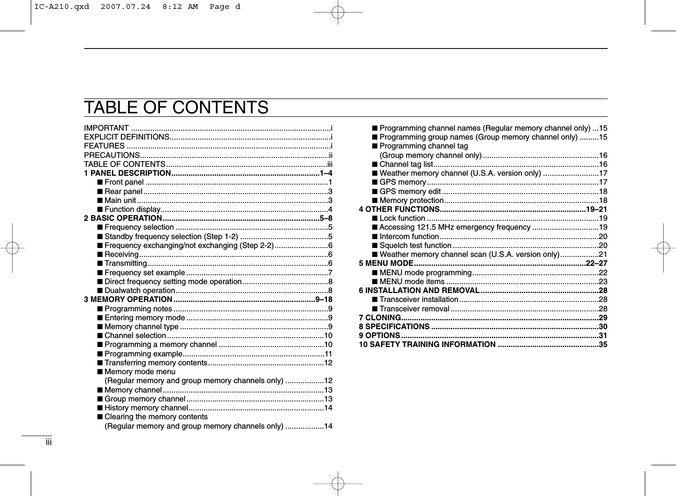
![72BASIC OPERATION02■Frequency set exampleThe following example shows to how to select 126.40 MHz in the standby frequency indicator and then exchange it to the activefrequency indicator.qweThe active frequency and the standby frequenies are exchanged.Previously used frequencies appear.Rotate the large tuning dial to change the standby frequency in MHz steps.Rotate the small tuning dial to change the standby frequency in kHz steps.121.805134.80RX126.805134.80RX126.405134.80RX134.805126.40RXRotate [O-DIAL] clockwise to select “126” MHz.Rotate [DIAL] counterclockwise to select “400” kHz.Push [↔].DO NOT push and hold. See “Direct frequnecy setting mode operation” on p. 8 if you make a mistake and do push and hold.IC-A210.qxd 2007.07.24 8:12 AM Page 7](https://usermanual.wiki/ICOM-orporated/297400.Manual-Revised/User-Guide-820686-Page-11.png)
![82BASIC OPERATION■Direct frequency settingmode operationThe direct frequency setting mode operation is useful whensetting the desired frequency directly to the active frequencyindicator.qPush and hold [↔]for 2 sec. to enter the direct frequencysetting mode.• The only active frequency is displayed.wSelect an operating frequency.• Refer to pgs. 5–6 in details.ePush [RCL] or [↔]to exit the direct frequency settingmode.■Dualwatch operationThe dualwatch operation monitors active and standby fre-quencies alternately. Therefore, it’s useful to monitor thestandby frequency while receiving the active frequency.qPush [DUAL] to enter dualwatch operation.• “DUAL” appears on the active frequency indicator.• The active or standby frequency‘s “RX”blinks when receiving sig-nal or opening the squelch.wPush [DUAL] again to exit dualwatch operation.• “DUAL” disappears.• You may also exit dualwatch by pushing [PTT].121.80RX129.405121.00RX DUAL RXIC-A210.qxd 2007.07.24 8:12 AM Page 8](https://usermanual.wiki/ICOM-orporated/297400.Manual-Revised/User-Guide-820686-Page-12.png)
![93MEMORY OPERATION0203■Programming notesïBlank channelA memory or group channel with no frequency content iscalled as a blank channel. When a blank channel is selectedwhile memory programming, “–––––” appears instead of afrequency.ïMemory protect functionIC-A210 has a memory protect function. The function pre-vents accidental changes or deletion.The function can be set in the MENU mode.■Entering memory mode• Push [RCL] to enter the memory mode.• Push [RCL] to set the selected memory channel frequencyto the standby frequency, then exit the memory mode.• Push and hold [RCL] for 2 sec. to exit the memory mode(The standby frequency is set the frequency before enter-ing the memory mode ).■Memory channel typeThe transceiver has 5-memory* channel types as follows.*Depends on versions, the transceiver has 5 different types of mem-ory channels.ïRegular memory channel (MEMORY)There are up to 10 available memory channels. The following functions are available:REPLACE, DELETE, REVIVE and CHANNEL NAME EDITfunctions.ïGroup memory channel (GRP01–GRP20)There are up to 200 group channels (10 CH ×20 Groups).The following functions are available:REPLACE, DELETE, REVIVE, GROUP NAME EDIT andCHANNEL TAG functions.ïWeather memory channel (WEATHER)(U.S.A. version ONLY)10 weather memory channels are available. They are used for monitoring NOAA (National Oceanic andAtmospheric Administration) broadcasts (reception of weathermemory channels possible in U.S.A. version only).ïHistory memory channel (HISTORY)There are up to 10 available history memory channels. The active frequency is written into history memory channelsautomatically when pushing [↔]to exchange the active andstandby frequency (except weather channels: U.S.A. versiononly).ïGPS memory channel (GPS)There are up to 10 available GPS memory channels.When connected to an external GPS receiver* equipped withan airport frequency database, the frequency data such asnearby airports can be transferred into GPS memory chan-nels .* Ask your dealer for available GPS receiver details.IC-A210.qxd 2007.07.24 8:12 AM Page 9](https://usermanual.wiki/ICOM-orporated/297400.Manual-Revised/User-Guide-820686-Page-13.png)
![103MEMORY OPERATION■Programming a memorychannelThis transceiver is equipped with 10 regular memory and 200group channels. You can program often-used frequencies intothem.qRotate [DIAL] and [O-DIAL] to set the desired frequencyfor the standby frequency indicator.wPush [RCL] to enter the memory mode.• The channel number appears.• The memory channel name also appears if it has been entered.eRotate [O-DIAL] to select the desired memory channeltype.• Select regular memory channel or group memory channel.rPush [MEM] again, and then rotate [O-DIAL] to select a“REPLACE” menu.• The memory channel number blinks.tRotate [DIAL] to select a memory channel to be pro-grammed.yPush [MEM], then the selected memory channel is pro-grammed.• “WRITE COMPLETED” appears on the display when the regularmemory channel is programmed.uPush [RCL] to exit the memory mode.■Channel selectionThe transceiver has 10 regular memory and 200 groupchannels (10 channels ×1 REGULAR MEMORY and 10channels ×20 GROUPS) for storage of often-usedfrequencies along with 6-character notes.qPush [RCL] to enter the memory mode.• The channel number appears.• The memory channel name also appears if it has been entered.wRotate [O-DIAL] to select the memory channel type.• Select from regular memory channel or group memory channel.eRotate [DIAL] to select the desired memory channel num-ber.Transferring the memory channel to the active fre-quency is necessary if operating at the memory chan-nel.Refer to “Transferring memory contents” (p. 12) for de-tails.rPush [RCL] to exit the memory mode.CH01127.005122.00RX MEMORYIC-A210.qxd 2007.07.24 8:12 AM Page 10](https://usermanual.wiki/ICOM-orporated/297400.Manual-Revised/User-Guide-820686-Page-14.png)
![113MEMORY OPERATION03■Programming exampleThe following is an example showing how to program 126.000 MHz into regular memory channel 4.“ ” appears when no frequency has been programmed into regular memory channel 4.“MEMORY” and regular memory channel number appear.“126.00” appears in the standby indicator.126.005134.80RXCH01134.80RX MEMORYCH04134.80RX MEMORYCH04126.000---.---134.80RX MEMORYREPLACE ÇCH04126.005134.80RX MEMORYSet a “126.000 MHz” in the standby indicator.qPush [RCL], then rotate [O-DIAL] to select “MEMORY”.wPush [MEM], then rotate [O-DIAL] to select “REPLACE.”rPush [MEM] to store the desired frequency into the selected regular memory channel.tSelect regular memory chan-nel 4 with [DIAL].e“WRITE COMPLETED” is displayed when the selected frequency is stored.Regular memory channel number blinks.TIP: Push and hold [MEM] for 2 sec. to program a displayed frequency to any blanket memory channel automatically, after stepq.NOTE: The programming is cancelled while all regular memory channels have already programmed.IC-A210.qxd 2007.07.24 8:12 AM Page 11](https://usermanual.wiki/ICOM-orporated/297400.Manual-Revised/User-Guide-820686-Page-15.png)
![123MEMORY OPERATION■Transferring memorycontentsThis function transfers a memory channel’s contents into theactive frequency indicator.qPush [RCL] to enter the memory mode.• The channel number appears.• The memory channel name also appears if it has been entered.wRotate [O-DIAL] to select the desired memory channeltype.• Select regular, group history, weather* or GPS memory channel.* Selectable depending on versions.eRotate [DIAL] to select a memory channel to be trans-ferred.rPush [↔], then the selected memory channel is trans-ferred into the active frequency indicator.• The memory mode is cancelled automatically.■Memory mode menu(Regular and group memorychannels only)ïREPLACEReplacing the selected memory channel to the standby fre-quency.ïDELETEDeleting the selected memory channel.ïREVIVEReturning the selected memory channel to its previous state.ïCH NAME (Regular memory channel only)Setting the channel name to the selected regular memorychannel.ïGRP NAME (Group memory channel only)Setting the group name to the selected memory group.ïCH TAG (Group memory channel only)Setting the channel tag to the selected memory channel (Se-lecting the group memory channel is the only option).ïDONEReturn to the memory mode.CH01127.005122.00RX MEMORY122.005127.00RX MEMORYPush [↔].IC-A210.qxd 2007.07.24 8:12 AM Page 12](https://usermanual.wiki/ICOM-orporated/297400.Manual-Revised/User-Guide-820686-Page-16.png)
![133MEMORY OPERATION03■Regular memory channelThe transceiver has 10 regular memory channels. 5 actionsare selectable.qPush [RCL] to enter the memory mode.• The channel number appears.• The memory channel name also appears if it has been entered.wRotate [O-DIAL] to select the regular memory channel.• “MEMORY” appears.ePush [MEM] again, then rotate [O-DIAL] to select a menuas follow.• The memory channel number blinks.rPush [MEM] to perform the selected action.■Group memory channelThe transceiver has 200 memory channels 200 groupchannels (10 channels ×20 groups). 6 actions are selectable.qPush [RCL] to enter the memory mode.• The channel number appears.• The memory channel name also appears if it has been entered.wRotate [O-DIAL] to select the group memory channel.• “GRP01–GRP20” appears.ePush [DIAL], and then rotate [O-DIAL] to select the mem-ory group from GRP01 to GRP20 if necessary.• The group and channel numbers blink.• Push [DIAL] again, or push [RCL] to set the memory group.rPush [MEM] again, rotate [O-DIAL] to select a menu asfollow.• The memory channel number blinks.tPush [MEM] to perform the selected action.CH01127.005122.00RX GRP01CH01127.005122.00RX MEMORYREPLACE Replace to the standby frequency.DELETE Delete the memory channel.REVIVE Revive the previous memory channel data.CH NAME Edit the memory channel name.DONE Do nothing and return to the memory mode.REPLACE Replace to the standby frequency.DELETE Delete the memory channel.REVIVE Revive the previous memory channel data.GRP NAME Edit the group name.CH TAG Set the memory channel as a tag channel.DONEDo nothing and return to the memory mode.IC-A210.qxd 2007.07.24 8:12 AM Page 13](https://usermanual.wiki/ICOM-orporated/297400.Manual-Revised/User-Guide-820686-Page-17.png)
![143MEMORY OPERATION■History memory channelThe transceiver has 10 history memory channels.The standby frequency is stored into a history memory chan-nel when pushing [↔].The frequency is stored into the history memory channel inorder from “CH01” to “CH10.”qPush [RCL] to enter the memory mode.• The channel number appears.• The memory channel name also appears if it has been entered.wRotate [O-DIAL] to select the history memory channel.• “HISTORY” appears.eRotate [DIAL] to select a desired channel.• Push [↔]to exchange the history memory channel frequency tothe active frequency if necessary.rPush [RCL] to exit the memory mode.■Clearing the memory contents(Regular and group memorychannels only)Unwanted memory channels can be cleared.qPush [RCL] to select memory mode.• The channel number appears.• The memory channel name also appears if it has been entered.wRotate [O-DIAL] to select the memory channel type.• Select from regular memory channel or group memory channel.ePush [MEM] again, then rotate [O-DIAL] to select“DELETE.”• The memory channel number blinks.rPush [MEM] to delete the memory channel data.•“-- -- -- -- -- --” appears momentarily, then the next selectablechannel appears.tPush [RCL] to exit the memory mode.CH01127.005122.00RX HISTORYCH01127.000127.000122.00RX MEMORYÅDELETE ÇCH01122.00RX MEMORYIC-A210.qxd 2007.07.24 8:12 AM Page 14](https://usermanual.wiki/ICOM-orporated/297400.Manual-Revised/User-Guide-820686-Page-18.png)
![153MEMORY OPERATION03■Programming channel names(Regular memory channel only)The regular memory channel can display a 6-character namein addition to the memory number.qPush [RCL], then rotate [O-DIAL] to select the desiredregular memory channel in the memory mode.• Rotate [O-DIAL] to select the memory channel type if necessary.wPush [MEM], then rotate [O-DIAL] to select “CH NAME.”ePush [MEM], then memory channel name’s 1st digitblinks.rRotate [DIAL] to select the desired character.• The character type as shown below is selectable.• Push [DIAL] to switch capital (A, B, C, ···) →lower case (A, B, C,···) →number (0, 1, 2, ···) →capital (A, B, C, ···) in order.tRotate [O-DIAL] to select the next input digit.yRepeat r–tto input the memory channel name.uPush [MEM] to decide the memory channel name.• Selectable characters■Programming group names(Group memory channel only)The group memory channel can display a 6-character namein addition to the group number (“GRP01”–“GRP20”).qPush [RCL], then rotate [O-DIAL] to select the desiredmemory channel in the memory mode.• Rotate [O-DIAL] to select the memory channel type if necessary.wPush [DIAL], and then rotate [O-DIAL] to select the mem-ory group from GRP01 to GRP20, if necessary.ePush [MEM], then rotate [O-DIAL] to select “GRP NAME”.rPush [MEM], then group name’s 1st digit blinks.tRotate [DIAL] to select the desired character.• The character type as shown left “Selectable characters” is se-lectable.• Push [DIAL] to switch capital (A, B, C, ···) →lower case (A, B, C,···) →number (0, 1, 2, ···) →capital (A, B, C, ···) in order.yRotate [O-DIAL] to select the next input digit.uRepeat t–yto input the group name.iPush [MEM] to decide the group name.0 1 2 3 4 5 6 7 8 9 : ; < = > ? @ A B C D E F G H I J K L M N O P Q R S T U V W X Y Z [ \ ]^ _ `a b c d e f g h i j k l m n o p q r s t u v w x y z { | } ~ ■! ” # $% & ’ ( ) ∗+ , – . /IC-A210.qxd 2007.07.24 8:12 AM Page 15](https://usermanual.wiki/ICOM-orporated/297400.Manual-Revised/User-Guide-820686-Page-19.png)
![163MEMORY OPERATION■Programming channel tag (Group memory channel only)The tag name can be set a 3-character name in addition tothe group number. It is convenient for separating memorytype.qPush [RCL], then rotate [O-DIAL] to select the desiredgroup memory channel in the memory mode.• Rotate [O-DIAL] to select the memory channel type if necessary.wPush [MEM], then rotate [O-DIAL] to select “CH TAG”when selecting “LABEL” in “Group memory channel dis-play” of the menu mode (p. 24)ePush [MEM], then rotate [DIAL] to select the desiredchannel tag.• The tag type as shown below is selectable.rPush [MEM] to decide the channel tag.• Selectable tags___ / TWR / GND / ATS / ATF / APP / ARR / AWS / CLR /CTF / DEP / FSS / RFS / UNI / MF / OTH / U-1 / U-2■Channel tag listTAG DISPLAYMEANSNAME Group*1GPS*2_ _ _ YES – Non-tagTWR YES YES TowerGND YES YES GroundATS YES YES ATISATF YES YES Air trafficAPP YES YES ApproachARR YES YES ArrivalAWS YES YES Automatic Weather StationCLR YES YES Clearance / DeliveryCTF YES YESCommon Traffic Advisory FrequencyDEP YES YES Departure FrequencyFSS YES YES Flight Service StationRFS YES YES Remote Flight Service StationUNI YES YES Unicom frequencyMF YES YES Mandatory frequencyOTH YES – OtherU-1 YES – User1 setting (Refer to p. 26)U-2 YES – User2 setting (Refer to p. 26)*1Group memory, *2GPS memoryCH01127.005122.00RX GRP01TWRIC-A210.qxd 2007.07.24 8:12 AM Page 16](https://usermanual.wiki/ICOM-orporated/297400.Manual-Revised/User-Guide-820686-Page-20.png)
![173MEMORY OPERATION03■GPS memoryWhen connected to an external GPS receiver* equipped withan airport frequency database, frequency data such asnearby airports can be transferred and made available in theGPS memory (maximum 10-memory channels).*Ask your dealer for available GPS receiver details.qPush [RCL] to enter the memory mode.• The channel number appears.wRotate [O-DIAL] to select the GPS memory channel.• “GPS” appears.eRotate [DIAL] to select a desired channel.rPush [RCL] to exit the GPS memory mode.■Weather memory channel (U.S.A. version only)The U.S.A. version has VHF marine WX (weather) channelreceiving capability for flight planning.qPush [RCL] to enter the memory mode.• The channel number appears.wRotate [O-DIAL] to select the weather memory channel.• “WEATHER” appears.eRotate [DIAL] to select a desired channel.rPush [RCL] to exit the weather memory mode.WX01162.555122.00RX DUAL WEATHERCH01 TWR122.055122.00RX GPS RJTJAirport codeTag nameChannel Frequency Channel FrequencyWX01 162.550 MHz WX06 162.500 MHzWX02 162.400 MHz WX07 162.525 MHzWX03 162.475 MHz WX08 161.650 MHzWX04 162.425 MHz WX09 161.775 MHzWX05 162.450 MHz WX10 163.275 MHz• Weather memory channel listNOTE: See the GPS receiver’s instruction manual whentransferring the frequency data in details.IC-A210.qxd 2007.07.24 8:12 AM Page 17](https://usermanual.wiki/ICOM-orporated/297400.Manual-Revised/User-Guide-820686-Page-21.png)
![183MEMORY OPERATION■GPS memory editThe received GPS memory data is stored to desired groupmemory channel.qPush [RCL] to enter the memory mode.• The channel number appears.• The memory channel name also appears if it has been entered.wRotate [O-DIAL] to select the GPS memory channel.• “GPS” appears.ePush [MEM] to enter the GPS memory channel edit mode,then rotate [O-DIAL] to select the desired group memory.• “GPS” and airport code blink.rPush [MEM] to store the GPS memory channel data to theselected group memory.tPush [RCL] to exit the memory mode.NOTE:The GPS memory data is overwritten if the settinggroup memory channel has already memorized other data.■Memory protectionThe transceiver has memory protection which inhibits to theediting (storing, deleting, replacing, etc.) of the memory groupmemory channels.Refer to “Memory Protection” (pgs. 18, 24) for details.IC-A210.qxd 2007.07.24 8:12 AM Page 18](https://usermanual.wiki/ICOM-orporated/297400.Manual-Revised/User-Guide-820686-Page-22.png)
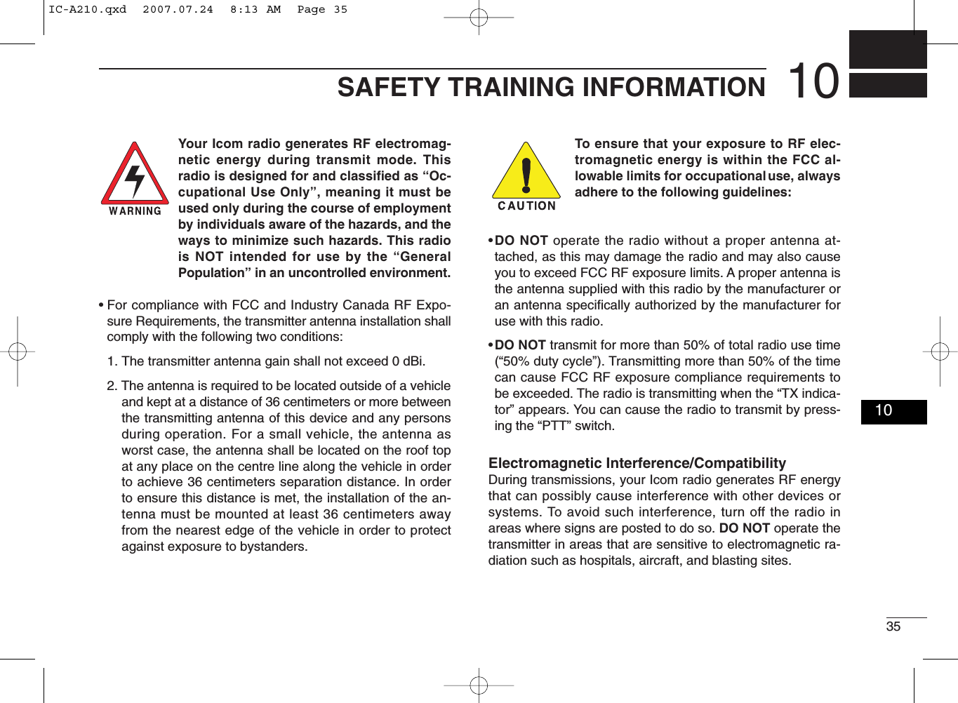
![194OTHER FUNCTIONS0304■Lock functionThe lock function prevents accidental frequency changes andaccidental function activation.qPush and hold [DIAL] for 2 sec. to turn the lock functionON.• “ ” appears when DIAL lock mode is selected.• “ ” appears when PANEL lock mode is selected.wTo turn the function OFF, repeat step qabove.• “ ” or “ ” disappears.■Accessing 121.5 MHzemergency frequencyThe IC-A210 can be set to the 121.5 MHz emergency fre-quency quickly. This function can be activated even when thekey lock function is in use.qPush [EC] to call the emergency frequency to the standbyfrequency, and then entering the dualwatch operation au-tomatically.wPush [↔]to transfer emergency frequency to the activefrequency if necessary.• “EC” appears.ePush [↔]to exit from the emergency frequency.• Set the frequency except 121.500 MHz before pushing [↔]tothe standby frequency if necessary.• “EC” disappears.NOTE: “EC” also appears on the display while the activefrequency is set to 121.500 MHz.OPODOPODNOTE: AUTOMATIC LOCK RELEASE FUNCTIONThis transceiver has an “Automatic Lock Release Function”which releases the Lock function automatically when an op-erator gets into a panic.The function performs when operating to push any keys (ex-cept [EC]) 8-times or rotating any dials (except [VOL]) 25-clicks for 5 sec.CONVENIENT!: Push and hold [EC] for 2 sec. to enterthe direct frequency setting mode (p. 8), and set the emer-gency frequency (121.5 MHz).• “EC” appears.IC-A210.qxd 2007.07.24 8:12 AM Page 19](https://usermanual.wiki/ICOM-orporated/297400.Manual-Revised/User-Guide-820686-Page-23.png)
![204OTHER FUNCTIONS■Intercom functionWhen 2-headphone and microphone jacks are connected tothe transceiver, these headsets can be used as a voice-acti-vated intercom.qEnter to the MENU mode.• See p.22 for details.wSet Intercom Usable Setting to ON.• See p.27 for details.eExit from the MENU mode.• See p.22 for details.rPush and hold [DUAL] for 2 sec. to enable the intercomfunction.• “ICS” appears.• The headphone audio output level can be selected“OFF,” “output level fixing (001–076)” or “interlocking with[VOL]” in the MENU mode (p. 23).• The microphone1 and microphone2 audio input levelscan be also selected “OFF” or “output level fixing(001–076)” in the MENU mode (p. 23).■Squelch test functionThis function opens the squelch manually for testing.qPush [VOL] to turn the squelch test function ON.• “TEST” appears.wTo turn the function OFF, repeat step qas above.• “TEST” disappears.IC-A210.qxd 2007.07.24 8:12 AM Page 20](https://usermanual.wiki/ICOM-orporated/297400.Manual-Revised/User-Guide-820686-Page-24.png)
![214OTHER FUNCTIONS■Weather memory channelscan (U.S.A. version only)Scanning searches for weather channel signals automaticallyand makes it easier to listen purposes.Repeatedly scans all weather memory channels.This function is available for the U.S.A. version only.qSet to the weather memory channel mode.wPush and hold [VOL] for 2 sec. to start weather memorychannel scan.• To change the scan direction, turn [DIAL].• “NO WTH” appears when no signal receives from WX01– WX10channels. Then the weather memory channel scan stops auto-matically.• “SEARCH“ flashes while scanning.ePush and hold [VOL] for 2 sec. again to stop the scan.162.555122.00RX WEATHERSEARCH04IC-A210.qxd 2007.07.24 8:12 AM Page 21](https://usermanual.wiki/ICOM-orporated/297400.Manual-Revised/User-Guide-820686-Page-25.png)
![225MENU MODE■MENU mode programmingMENU mode is available at power ON and allows you to setseldom-changed settings. In this way you can customizetransceiver operations to suit your preferences and operatingstyle.DOperating MENU modeqRotate [VOL] to turn the transceiver’s power ON.wPush [RCL] to set VFO mode if memory mode is selected.ePush and hold [RCL] for 2 sec. to enter the MENU mode.rRotate [O-DIAL] to select setting items.tRotate [DIAL] to select the desired condition.yPush [RCL] to exit MENU mode, and returning to the pre-vious operating condition.• MENU mode itemsMENU MODEHP LEVEL AF GAIN01/31RCLMEMOFFVOLPUSHTESTCOMMDUALECiA210AF GAINOFF001076Desired condition settingHP LEVELINCOM LV1INCOM LV2MIC1 SQLMenu mode items settingMenu mode items Items numberSetting valuep. 23HP LEVELGRP MEMORYINCOM LV2INCOM LV1MIC1 SQLMIC2 SQLANLSQL LEVELFM SQL LV**Not available on all versions.LOCK MODEDW INTERVALMEM PROTECTMIC2 GAINMIC1 GAINSIDETONE LVTX MIC SELDISP HIGHDISP MAN.AUX LEVELDISP MODEDISP LOWDISP RESP.FREQ DISPU-1 ID SETU-2 ID SETAUX INBEEPINCOM MODETIME OUTMEM CLEARp. 26p. 27p. 25p. 24p. 25IC-A210.qxd 2007.07.24 8:12 AM Page 22](https://usermanual.wiki/ICOM-orporated/297400.Manual-Revised/User-Guide-820686-Page-26.png)
![235MENU MODE■MENU mode itemsDHeadphone Level “HP LEVEL”Set the headphone output level while receiving.• AF gain : The output level is same as [VOL].• OFF (0) : While muting the headphone.• 001–080 : Setting audio level from 1 to 80.DIntercom1 Microphone Audio Input Level“INCOM LV1”Set the intercom1 microphone input level.• OFF (0) : While muting the intercom1 microphone.• 001–080 : Setting the intercom1 input level from 1 to 80.DIntercom2 Microphone Audio Input Level“INCOM LV2”Set the intercom2 microphone input level.• OFF (0) : While muting the intercom2 microphone.• 001–076 : Setting the intercom2 input level from 1 to 80..DIntercom1 Squelch Level “MIC1 SQL”Set the intercom1 squelch level.The setting level is required to open the squelch when speak-ing to the intercom1.• OFF (0) : While opening the intercom1 squelch.• 001–030 : Setting the intercom1 squelch level from 1 to 30.DIntercom2 Squelch Level “MIC2 SQL”Set the intercom2 squelch level.The setting level is required to open the squelch when speak-ing to the intercom2.• OFF (0) : While opening the intercom2 squelch.• 001–030 : Setting the intercom2 squelch level from 1 to 30.DAutomatic Noise Limiter “ANL”The ANL (Automatic Noise Limiter) function reduces noisecomponents such as that caused by engine ignition systemswhile receiving.• OFF : The ANL function is OFF.• ON : The ANL function is ON.05IC-A210.qxd 2007.07.24 8:12 AM Page 23](https://usermanual.wiki/ICOM-orporated/297400.Manual-Revised/User-Guide-820686-Page-27.png)
![245MENU MODE■MENU mode items (Continued)DAM Squelch Level “SQL LEVEL”Set the squelch level for AM mode operation.In order to receive signals properly, as well as for the scan tofunction effectively, the squelch must be adjusted to theproper level.• –010–010 : Setting AM squelch level from –10 to 10.DFM Squelch Level “FM SQL LV”(U.S.A. version only)Set the squelch level for FM mode operation.• –010–010 : Setting FM squelch level from –10 to 10.DLock Mode “LOCK MODE”Set the lock function effective area.• OFF : The lock function is nonfunctional.• DIAL : The lock function applies to [DIAL].• PANEL : The lock function applies to buttons on the front panel.DDualwatch Interval “DW INTERVAL”Set the interval time while operating dualwatch or weatherscan.• FAST : The interval time sets to 300 msec.• MID : The interval time sets to 600 msec.• SLOW : The interval time sets to 2 sec..DMemory Protection “MEM PROTECT”Set the memory protection to regular memory channels andgroup memory channels.Editing the regular memory and group memory channels isinhibited while the protection is ON.• OFF : The memory protection is OFF.• ON : The memory protection is ON.DGroup Memory Channel Display“GRP MEMORY”Set the displaying whether the label displays or not.• CH : The only channel number is displayed.• LABEL : The label is also displayed.DMicrophone1 Gain “MIC1 GAIN”Set the microphone1’s gain.• –010–010 : Setting the microphone1’s gain from –10 to 10.DMicrophone2 Gain “MIC2 GAIN”Set the microphone2’s gain.• –010–010 : Setting the microphone2’s gain from –10 to 10.IC-A210.qxd 2007.07.24 8:12 AM Page 24](https://usermanual.wiki/ICOM-orporated/297400.Manual-Revised/User-Guide-820686-Page-28.png)
![265MENU MODE■MENU mode items (Continued)DDimmer Brightness (Manually) “DISP MAN.”Set the brightness manually to suit your own preferences.• 0–100 : Setting dimmer level manually from 0 (OFF) to 100.DDimmer Response “DISP RESP.”Set the dimmer switching speed when selecting “AUTO” atthe “Dimmer Mode.”• STANDARD: Selecting switch speed is normal.• FAST : Selecting switch speed is fast.DFrequency Display “FREQ DISP”Set the 1 kHz digit frequency displaying to the OLED.• OFF : The 1 kHz digit always does not display on the OLED.• ON : The 1 kHz digit always display on the OLED.• ZERO SUPP.: The 1 kHz digit display on the OLED (Except the digitis 0).DUSER-1 Setting “U-1 ID SET”Set the USER-1, channel tag, to the desired ID.qPush [MEM] to enter the U-1 ID edit mode.wRotate [DIAL] to select the desired character.eRotate [O-DIAL] to select the next input digit.rRepeat w–eto input the U-1 ID.tPush [MEM] again to store the U-1 ID, and exit the edit mode.DUSER-2 Setting “U-2 ID SET”Set the USER-2, channel tag, to the desired ID.qPush [MEM] to enter the U-2 ID edit mode.wRotate [DIAL] to select the desired character.eRotate [O-DIAL] to select the next input digit.rRepeat w–eto input the U-2 ID.tPush [MEM] again to store the U-2 ID, and exit the edit mode.DExternal Input “AUX IN”Set the external input mode.• OFF : The external input does not use.• ON : The external input is available while squelch is closing.• INCOM : The external input is available with the intercom opera-tions as following.- The intercom function is OFF.- While the intercom function does not use.- While audio signal does not input to the intercom’s mi-crophone.IC-A210.qxd 2007.07.24 8:12 AM Page 26](https://usermanual.wiki/ICOM-orporated/297400.Manual-Revised/User-Guide-820686-Page-30.png)
![275MENU MODE■MENU mode items (Continued)DExternal Input Level “AUX LEVEL”Set the external input level.• OFF (0) : The external input does not operate.• 001–080 : Setting the external input level from 1 to 80.• AF GAIN : Interlocking with [VOL].DBeep Tone Level “BEEP”Confirmation beep tones normally sound when storing mem-ory, operating time-out-timer function, etc. These can be setthe desired beep level as you prefer.• OFF (0) : The beep tone turns OFF.• 001–100 : Setting the beep tone level from 1 to 100.DIntercom Usable Setting “INCOM MODE” Set the intercom using or not.• ON : The intercom is usable.• OFF : The intercom is unusable.DTime-Out-Timer “TIME OUT”To prevent accidental prolonged transmission, etc., the trans-ceiver has a time-out-timer function. This timer starts when atransmission begins, and will cut off the transmission whenthe time set in the timer elapses.• 020–240 : Setting time-out-timer starting period from 20 sec. to240 sec. at 10 sec. intervals.DMemory Clear “MEM CLEAR”Setting values in the CPU are cleared.Push and hold [MEM] for 2 sec., the CPU is reset as follow.• MENU : MENU mode items are reset.• MEMORY : Stored memories are reset.• ALL : All CPU data is reset. 05IC-A210.qxd 2007.07.24 8:12 AM Page 27](https://usermanual.wiki/ICOM-orporated/297400.Manual-Revised/User-Guide-820686-Page-31.png)