ICOM orporated 297400 VHF Air Band Transceiver User Manual IC A210
ICOM Incorporated VHF Air Band Transceiver IC A210
Contents
- 1. Manual Revised
- 2. User Manual
Manual Revised
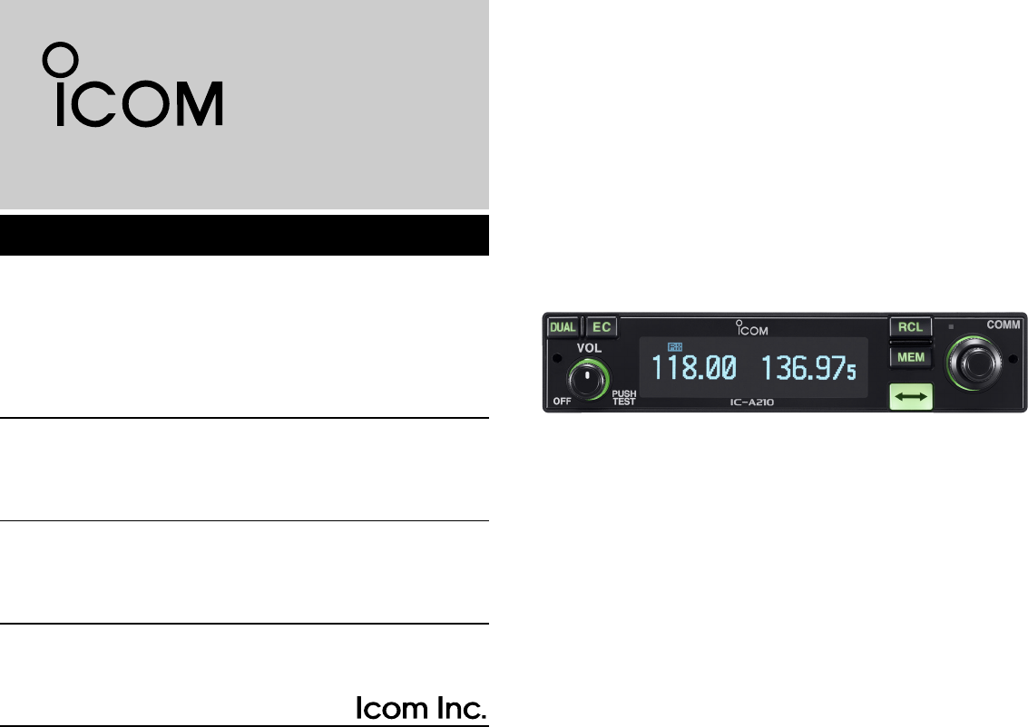
iA210
VHF AIR BAND TRANSCEIVER
INSTRUCTION MANUAL
This device complies with Part 15 of the FCC
Rules. Operation is subject to the condition that this
device does not cause harmful interference.
IC-A210.qxd 2007.07.24 8:12 AM Page a
i
IMPORTANT
READ ALL INSTRUCTIONS carefully and completely
before using the transceiver.
SAVE THIS INSTRUCTION MANUAL —This in-
struction manual contains important operating instructions for
the IC-A210.
EXPLICIT DEFINITIONS
The explicit definitions below apply to this instruction manual.
R
Icom, Icom Inc. and the logo are registered trademarks of Icom Incor-
porated (Japan) in the United States, the United Kingdom, Germany, France,
Spain, Russia and/or other countries.
IBM is a registered trademark of International Business Machines.
Microsoft and Windows are registered trademarks of Microsoft Corporation in
the U.S.A. and other countries.
FEATURES
❍Large, bright OLED display
A fixed mount VHF airband first! The IC-A210 has an organic light
emitting diode (OLED) display. All man-made lighting emits its own
light and display offers many advantages in brightness, not bright-
ness, vividness, high contrast, wide viewing angle and response time
compared to a conventional display. In addition, the auto dimmer
function adjusts the display for optimum brightness at day or night.
❍Easy channel selection
It’s fast and easy to select any of memory channels in the IC-A210.
The “flip-flop” arrow button switches between active and standby
channels. The dualwatch function allows you to monitor two channels
simultaneously. In addition, the history memory channel stores the
last 10 channels used and allows you to recall those channels easily.
❍GPS memory function
When connected to an external GPS receiver* equipped with an air-
port frequency database, the IC-A210 will instantly tune in the local
airport frequency as you fly into its airspace.
*Ask your dealer for available GPS receiver details.
❍13.8 V/27.5 V DC power source
The built-in DC-DC converter accepts a 13.8/27.5 V DC power
source. The IC-A210 is easily installed in most airplanes or vehicles.
❍Intercom function
The IC-A210 has a built-in voice activated intercom function allowing
the pilot to talk with a co-pilot via headset. The IC-A210 has ad-
justable audio level and squelch control functions.
IC-A210.qxd 2007.07.24 8:12 AM Page b

DO NOT push the PTT when not actually desiring to trans-
mit.
AVOID using or placing the transceiver in direct sunlight or
in areas with temperatures below –20°C (–4°F) or above
+55°C (+131°F).
AVOID placing the transceiver in excessively dusty envi-
ronments.
AVOID placing the transceiver against walls. This will ob-
struct heat dissipation.
AVOID the use of chemical agents such as benzine or al-
cohol when cleaning, as they damage the transceiver sur-
faces.
BE CAREFUL! The transceiver will become hot when
operating continuously for long periods.
PRECAUTIONS
ii
RWARNING! NEVER operate the transceiver with a
headset or other audio accessories at high volume levels.
Hearing experts advise against continuous high volume op-
eration. If you experience a ringing in your ears, reduce the
volume level or discontinue use.
NEVER connect the transceiver to an AC outlet or to a
power source of more than 28 V DC. Such a connection will
damage the transceiver.
NEVER connect the transceiver to a power source that is
DC fused at more than 5 A. Accidental reverse connection will
be protected by this fuse, higher fuse values will not give any
protection against such accidents and the transceiver will be
ruined.
DO NOT operate the transceiver near unshielded electrical
blasting caps or in an explosive atmosphere.
DO NOT connect the transceiver to a power source using
reverse polarity. This connection will not only blow fuses but
also may damage the transceiver.
DO NOT place unit in a non-secure place to avoid inad-
vertent use by children.
FCC caution: Changes or modifications to this transceiver, not
expressly approved by Icom Inc., could void your authority to
operate this transceiver under FCC regulations.
IC-A210.qxd 2007.07.24 8:12 AM Page c

iii
IMPORTANT .............................................................................................i
EXPLICIT DEFINITIONS...........................................................................i
FEATURES ...............................................................................................i
PRECAUTIONS........................................................................................ii
TABLE OF CONTENTS...........................................................................iii
1 PANEL DESCRIPTION.....................................................................1–4
■ Front panel .....................................................................................1
■ Rear panel......................................................................................3
■ Main unit.........................................................................................3
■ Function display..............................................................................4
2 BASIC OPERATION.........................................................................5–8
■ Frequency selection .......................................................................5
■ Standby frequency selection (Step 1-2) .........................................5
■ Frequency exchanging/not exchanging (Step 2-2).........................6
■ Receiving........................................................................................6
■ Transmitting....................................................................................6
■ Frequency set example ..................................................................7
■ Direct frequency setting mode operation........................................8
■ Dualwatch operation.......................................................................8
3 MEMORY OPERATION ..................................................................9–18
■ Programming notes ........................................................................9
■ Entering memory mode ..................................................................9
■ Memory channel type .....................................................................9
■ Channel selection.........................................................................10
■ Programming a memory channel .................................................10
■ Programming example..................................................................11
■ Transferring memory contents......................................................12
■ Memory mode menu
(Regular memory and group memory channels only) ..................12
■ Memory channel...........................................................................13
■ Group memory channel................................................................13
■ History memory channel...............................................................14
■ Clearing the memory contents
(Regular memory and group memory channels only) ..................14
■ Programming channel names (Regular memory channel only) ...15
■ Programming group names (Group memory channel only) .........15
■ Programming channel tag
(Group memory channel only)......................................................16
■Channel tag list.............................................................................16
■Weather memory channel (U.S.A. version only) ..........................17
■GPS memory................................................................................17
■GPS memory edit .........................................................................18
■Memory protection........................................................................18
4 OTHER FUNCTIONS....................................................................19–21
■Lock function ................................................................................19
■Accessing 121.5 MHz emergency frequency ...............................19
■Intercom function..........................................................................20
■Squelch test function ....................................................................20
■Weather memory channel scan (U.S.A. version only)..................21
5 MENU MODE................................................................................22–27
■MENU mode programming...........................................................22
■MENU mode items .......................................................................23
6 INSTALLATION AND REMOVAL.......................................................28
■Transceiver installation.................................................................28
■Transceiver removal .....................................................................28
7 CLONING............................................................................................29
8 SPECIFICATIONS ..............................................................................30
9 OPTIONS ............................................................................................31
10 SAFETY TRAINING INFORMATION ...............................................35
TABLE OF CONTENTS
IC-A210.qxd 2007.07.24 8:12 AM Page d
1
1
PANEL DESCRIPTION
01
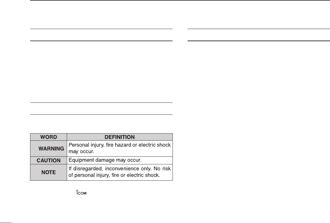
■Front panel
qDUAL SWITCH [DUAL]
➥Push to turn dualwatch operation ON or OFF (p. 8).
➥Push and hold for 2 sec. to turn the intercom function
ON or OFF.
wEMERGENCY CHANNEL SWITCH [EC]
➥Push to set the emergency frequency (121.5 MHz) to
the standby frequency (p. 19).
➥Push and hold for 2 sec. to enter the direct frequency
setting mode (p. 8), and set the emergency frequency
(121.5 MHz) (p. 19).
eVOLUME/POWER SWITCH [VOL]
➥Turn [VOL] to switch the power ON and OFF (p. 5).
➥Adjusts the audio output level.
The volume level bar appears while rotating [VOL].
➥Push to set the squelch test function ON or OFF (p. 20).
➥Push and hold for 2 sec. to start the weather channel
(U.S.A. version only) scan (p. 21).
rFREQUENCY EXCHANGE SWITCH (FLIP-FLOP)[↔]
➥Push to exchange the standby frequency with the ac-
tive frequency (p. 6).
➥Push and hold for 2 sec. to enter direct frequency set-
ting mode (p. 8).
RCL
MEM
OFF
VOL
PUSH
TEST
COMM
DUAL
EC
iA210
CH09 SAMPLE
121.525
118.00
RX MEMORY
eytriouqw
IC-A210.qxd 2007.07.24 8:12 AM Page 1
2
1PANEL DESCRIPTION
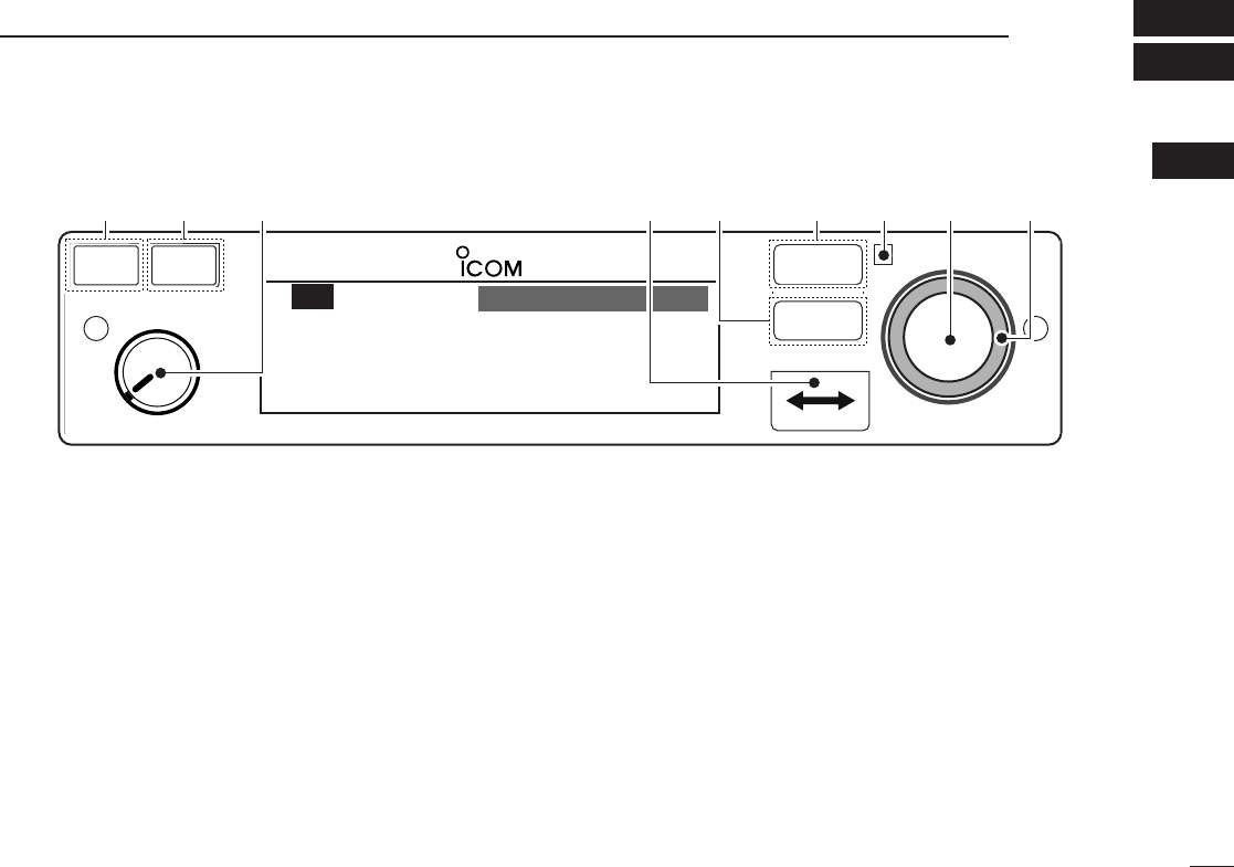
■Front panel (Continued)
tMEMORY SWITCH [MEM]
➥Push and hold for 2 sec. to be programmed a displayed
frequency to any blank regular memory channel or
delete/revive the selected memory channel (depending
on the operating mode) (p. 9).
➥Push to display the memory mode menu, and operate
selected menu (p. 9).
yRECALL SWITCH [RCL]
➥Push to enter/exit the memory mode (p. 9).
➥Push and hold for 2 sec. to enter the menu mode
(p. 22).
uLIGHT-SENSITIVE DETECTOR
This detector senses ambient light. The detector is used
to adjust “Dimmer brightness (Low/High)” (p. 25) automat-
ically when “Dimmer Mode” (p. 25) sets to ‘AUTO.’
iINNER (Small) TUNING DIAL [DIAL]
➥Rotate to set the standby frequencies (kHz digit) (p. 5),
memory channels (p. 10), MENU mode conditions
(p. 22), etc.
➥Push and hold for 2 sec. to turn the dial/panel lock func-
tion ON (p. 19).
oOUTER (Large) TUNING DIAL [O-DIAL]
➥Rotate to set the standby frequencies (MHz digit) (p. 5),
group memory channel (p. 13), cursor position (p. 15),
etc.
➥Rotate to change the scan direction while scanning
(p. 21).
RCL
MEM
OFF
VOL
PUSH
TEST
COMM
DUAL
EC
iA210
CH09 SAMPLE
121.525
118.00
RX MEMORY
eytriouqw
IC-A210.qxd 2007.07.24 8:12 AM Page 2
3
1
PANEL DESCRIPTION
01
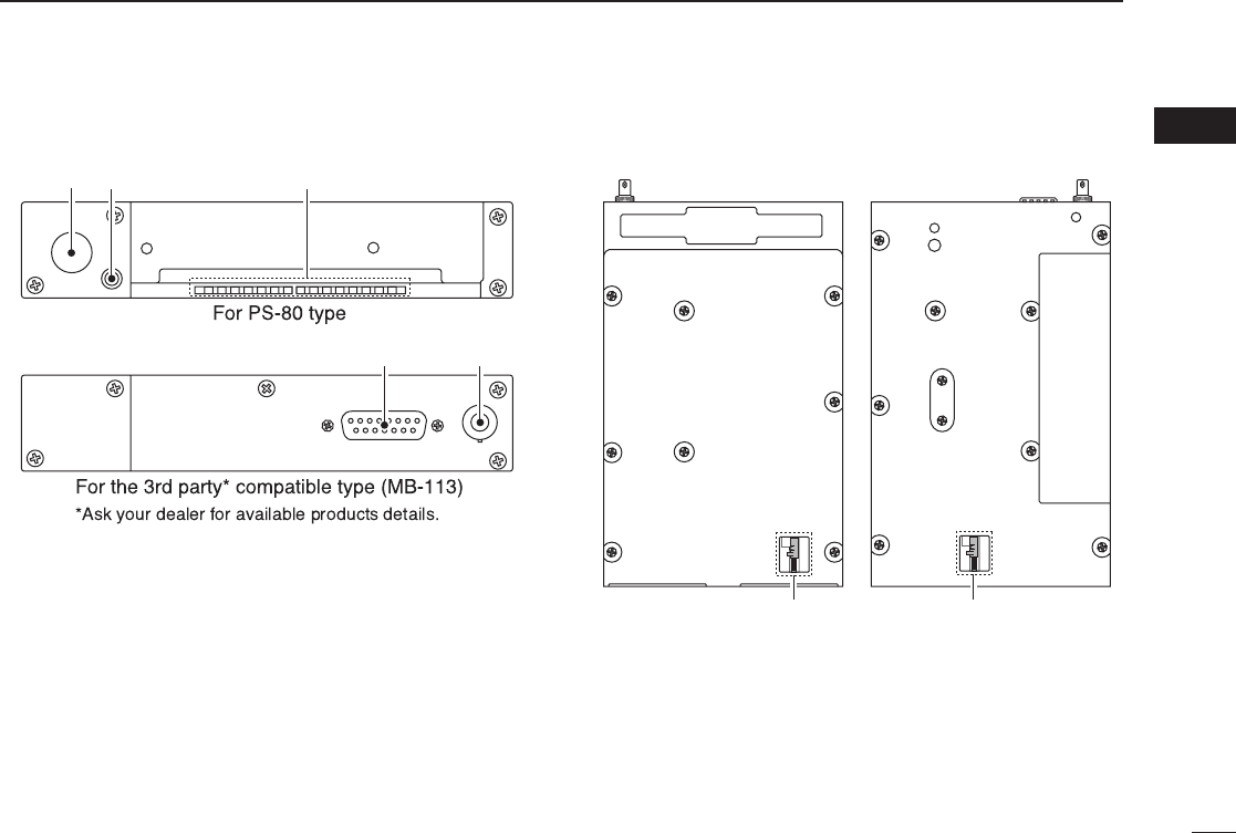
■Rear panel
qANTENNA CONNECTOR
Connects an antenna connector.
wDATA JACK
Connects a 3rd party GPS receiver*1or optional cloning
cable (OPC-1529R).
*1Ask your dealer for available GPS receiver details.
eDC, MICROPHONE, SPEAKER AND HEADPHONE
JACK
Connects a 13.8 V or 27.5 V DC power supply, speaker
and headphone.
Refer to the “INSTALLATION GUIDE” in details.
■Main unit
qMetal catch (For Icom products)
Use to attach to an installation rack for Icom products
(p. 28).
wMetal catch (For 3rd party products*)
Use to attach to an installation rack for 3rd party products*
(p. 28).
*Ask your dealer for available products details.
q w
e q
e
• Top view • Bottom view
q w
IC-A210.qxd 2007.07.24 8:12 AM Page 3
4
1PANEL DESCRIPTION
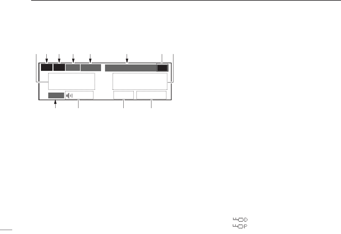
■Function display
qACTIVE FREQUENCY INDICATOR
➥Shows the active frequency (p. 6).
➥Shows the MENU mode items in the MENU mode
(p. 22).
wTX INDICATOR
Appears while transmitting (p. 6).
eRX INDICATOR
➥Appears when receiving a signal on the active fre-
quency signal (p. 6).
➥Appears when receiving a signal on the standby fre-
quency signal while dualwatch operation (p. 8).
➥Appears when opening the active frequency’s squelch
function (p. 6).
rINTERCOM INDICATOR
Appears when the intercom function is in use (p. 20).
tDUALWATCH INDICATOR
Appears when the dualwatch function is active (p. 8).
yMEMORY CONDITION INDICATOR
➥Indicates “MEMORY” when the regular memory channel
is selected (p. 13).
➥Indicates “GRP01–GRP20” when the group memory
channel is selected (p. 13).
The group name is also indicated if the name has been
entered.
➥Indicates “HISTORY” when the history memory chan-
nel is selected (p. 14).
➥Indicates “WEATHER” when the weather memory chan-
nel is selected (U.S.A. version only) (p. 17).
➥Indicates “GPS” when the GPS memory channel is se-
lected (The 3rd party GPS receiver is required) (p. 17).
uSTANDBY FREQUENCY INDICATOR
➥Shows the standby frequency (p. 5).
➥Shows the setting values in the MENU mode (p. 22).
iCHANNEL NAME INDICATOR
Shows the channel name during memory mode (p. 15).
oMEMORY CHANNEL INDICATOR
Shows the selected memory channel number during mem-
ory mode (p. 13).
!0 TEST INDICATOR
Appears while the squelch test function is active (p. 20).
!1 LOCK INDICATOR (p. 19)
➥Indicates “ ”while the dial lock function is in use.
➥Indicates “ ”while the panel lock function in use.
CH09 SAMPLE
TEST
121.525
118.00
RX DUAL MEMORY RX
ICS
O
F
D
TX
etr y e
io!1
uq
!0
w
IC-A210.qxd 2007.07.24 8:12 AM Page 4

5
2
BASIC OPERATION
01
02
■Frequency selection
IC-A210 has 2 ways to select the desired frequency.
ïGeneral frequency selection
Select the desired frequency which is used for the next oper-
ating frequency in the standby frequency indicator. Then ex-
change the active frequency for the standby frequency.
NOTE: Operate from “Standby frequency selection
(Step 1-2)” to “Frequency exchanging (Step 2-2)” as pgs. 5–6.
ïDirect frequency selection
The desired frequency direct selection is available.
Refer to “Direct frequency selection mode operation.”
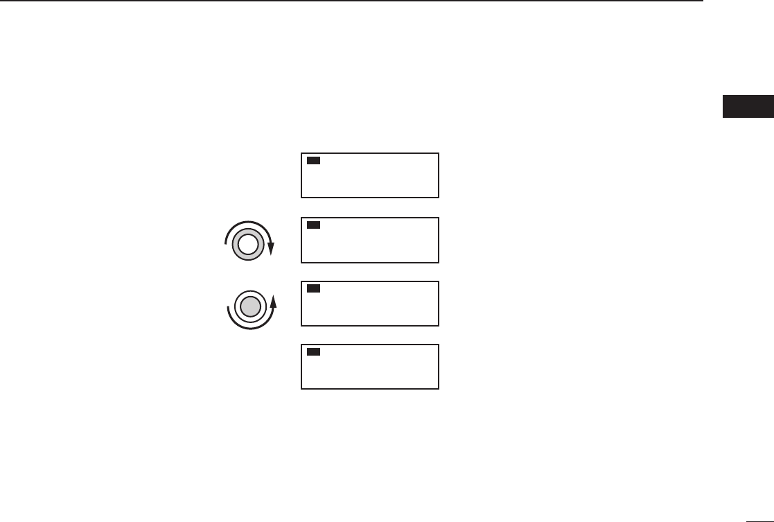
■Standby frequency selection
(Step 1-2)
qRotate [VOL] clockwise to turn power ON.
• Previously used frequencies appear in the active and
standby frequency indicators.
wRotate [DIAL] and [O-DIAL] to select the desired fre-
quency to the standby frequency.
• The active frequency is not affected.
• Rotate [O-DIAL] to set above 1 MHz digit.
• Rotate [DIAL] to set below 100 kHz digit.
•Set the frequency step* in the menu mode, if necessary (p. 27).
*Available for depending on versions.
TIP: For quick frequency setting, often used frequencies
can be programmed into memory channels. Refer to “MEM-
ORY OPERATION” (pgs. 9–18).
When a memory channel is recalled, the previous standby
frequency is erased.
CAUTION:
DO NOT turn the power ON until the aircraft engines have
been started. It is very important for protection of the power
supply circuit.
IC-A210.qxd 2007.07.24 8:12 AM Page 5

6
2BASIC OPERATION
■Frequency exchanging/
not exchanging (Step 2-2)
qAfter selecting the standby frequency, push [↔]to ex-
change the standby frequency with the active frequency.
•Rotate [VOL] to set the volume level, if necessary.
• When receiving a signal, “RX” appears and audio is emitted from
the speaker or headset.
•Further adjustment of audio level may be necessary at this point.
• Adjust the squelch level in the menu mode, if necessary (p. 24).
wPush and hold [PTT] to transmit, then speak into the mi-
crophone.
• Transmit indicator “TX” lights.
eRelease [PTT] to receive.
Frequency exchanging can be also performed remotely from
the yoke-mounted frequency exchange switch.
■Receiving
qSelect an operating frequency.
• Refer to pgs. 5–6 in details.
• “RX” appears when receiving a signal or opening squelch.
wPush [VOL] to open the squelch manually.
• Refer to p. 20 “Squelch test function” in details.
eRotate the volume control to adjust the audio level.
■Transmitting
qSelect the yoke-mounted communication/intercom switch
to the “communication” position.
wSelect an operating frequency.
• Refer to pgs. 5–6 in details.
ePush the PTT switch.
• “TX” appears.
rSpeak into the microphone at your normal voice level.
• DO NOT set the microphone too closely to your mouth or speak
too loudly. This may distort the signal.
tRelease the PTT switch to receive.
TIP: The intercom function is useful for swift communica-
tion between the pilot and co-pilot.
Set the communication/intercom switch on the VHF control
panel to the “intercom” position. Voice signals from the mi-
crophone are sent to both the pilot and co-pilot’s headsets.
NOTE: To prevent interference, listen on the frequency be-
fore transmitting. If the frequency is busy, wait until the fre-
quency is clear.
NOTE: DO NOT push and hold [↔]continuously. Oth-
erwise the standby frequency disappears. If this happens,
again push and hold [↔]until the standby frequency reap-
pears.
IC-A210.qxd 2007.07.24 8:12 AM Page 6
7
2
BASIC OPERATION
02
■Frequency set example
The following example shows to how to select 126.40 MHz in the standby frequency indicator and then exchange it to the active
frequency indicator.
q
w
eThe active frequency and the standby
frequenies are exchanged.
Previously used frequencies appear.
Rotate the large tuning dial to change
the standby frequency in MHz steps.
Rotate the small tuning dial to change
the standby frequency in kHz steps.
121.805
134.80
RX
126.805
134.80
RX
126.405
134.80
RX
134.805
126.40
RX
Rotate [O-DIAL] clockwise to
select “126” MHz.
Rotate [DIAL] counterclockwise
to select “400” kHz.
Push [↔].
DO NOT push and hold. See
“Direct frequnecy setting mode
operation” on p. 8 if you make a
mistake and do push and hold.
IC-A210.qxd 2007.07.24 8:12 AM Page 7

8
2BASIC OPERATION
■Direct frequency setting
mode operation
The direct frequency setting mode operation is useful when
setting the desired frequency directly to the active frequency
indicator.
qPush and hold [↔]for 2 sec. to enter the direct frequency
setting mode.
• The only active frequency is displayed.
wSelect an operating frequency.
• Refer to pgs. 5–6 in details.
ePush [RCL] or [↔]to exit the direct frequency setting
mode.
■Dualwatch operation
The dualwatch operation monitors active and standby fre-
quencies alternately. Therefore, it’s useful to monitor the
standby frequency while receiving the active frequency.
qPush [DUAL] to enter dualwatch operation.
• “DUAL” appears on the active frequency indicator.
• The active or standby frequency‘s “RX”blinks when receiving sig-
nal or opening the squelch.
wPush [DUAL] again to exit dualwatch operation.
• “DUAL” disappears.
• You may also exit dualwatch by pushing [PTT].
121.80
RX
129.405
121.00
RX DUAL RX
IC-A210.qxd 2007.07.24 8:12 AM Page 8

9
3
MEMORY OPERATION
02
03
■Programming notes
ïBlank channel
A memory or group channel with no frequency content is
called as a blank channel. When a blank channel is selected
while memory programming, “–––––” appears instead of a
frequency.
ïMemory protect function
IC-A210 has a memory protect function. The function pre-
vents accidental changes or deletion.
The function can be set in the MENU mode.
■Entering memory mode
• Push [RCL] to enter the memory mode.
• Push [RCL] to set the selected memory channel frequency
to the standby frequency, then exit the memory mode.
• Push and hold [RCL] for 2 sec. to exit the memory mode
(The standby frequency is set the frequency before enter-
ing the memory mode ).
■Memory channel type
The transceiver has 5-memory* channel types as follows.
*Depends on versions, the transceiver has 5 different types of mem-
ory channels.
ïRegular memory channel (MEMORY)
There are up to 10 available memory channels.
The following functions are available:
REPLACE, DELETE, REVIVE and CHANNEL NAME EDIT
functions.
ïGroup memory channel (GRP01–GRP20)
There are up to 200 group channels (10 CH ×20 Groups).
The following functions are available:
REPLACE, DELETE, REVIVE, GROUP NAME EDIT and
CHANNEL TAG functions.
ïWeather memory channel (WEATHER)
(U.S.A. version ONLY)
10 weather memory channels are available.
They are used for monitoring NOAA (National Oceanic and
Atmospheric Administration) broadcasts (reception of weather
memory channels possible in U.S.A. version only).
ïHistory memory channel (HISTORY)
There are up to 10 available history memory channels.
The active frequency is written into history memory channels
automatically when pushing [↔]to exchange the active and
standby frequency (except weather channels: U.S.A. version
only).
ïGPS memory channel (GPS)
There are up to 10 available GPS memory channels.
When connected to an external GPS receiver* equipped with
an airport frequency database, the frequency data such as
nearby airports can be transferred into GPS memory chan-
nels .
* Ask your dealer for available GPS receiver details.
IC-A210.qxd 2007.07.24 8:12 AM Page 9

10
3MEMORY OPERATION
■Programming a memory
channel
This transceiver is equipped with 10 regular memory and 200
group channels. You can program often-used frequencies into
them.
qRotate [DIAL] and [O-DIAL] to set the desired frequency
for the standby frequency indicator.
wPush [RCL] to enter the memory mode.
• The channel number appears.
• The memory channel name also appears if it has been entered.
eRotate [O-DIAL] to select the desired memory channel
type.
• Select regular memory channel or group memory channel.
rPush [MEM] again, and then rotate [O-DIAL] to select a
“REPLACE” menu.
• The memory channel number blinks.
tRotate [DIAL] to select a memory channel to be pro-
grammed.
yPush [MEM], then the selected memory channel is pro-
grammed.
• “WRITE COMPLETED” appears on the display when the regular
memory channel is programmed.
uPush [RCL] to exit the memory mode.
■Channel selection
The transceiver has 10 regular memory and 200 group
channels (10 channels ×1 REGULAR MEMORY and 10
channels ×20 GROUPS) for storage of often-used
frequencies along with 6-character notes.
qPush [RCL] to enter the memory mode.
• The channel number appears.
• The memory channel name also appears if it has been entered.
wRotate [O-DIAL] to select the memory channel type.
• Select from regular memory channel or group memory channel.
eRotate [DIAL] to select the desired memory channel num-
ber.
Transferring the memory channel to the active fre-
quency is necessary if operating at the memory chan-
nel.
Refer to “Transferring memory contents” (p. 12) for de-
tails.
rPush [RCL] to exit the memory mode.
CH01
127.005
122.00
RX MEMORY
IC-A210.qxd 2007.07.24 8:12 AM Page 10
11
3
MEMORY OPERATION
03
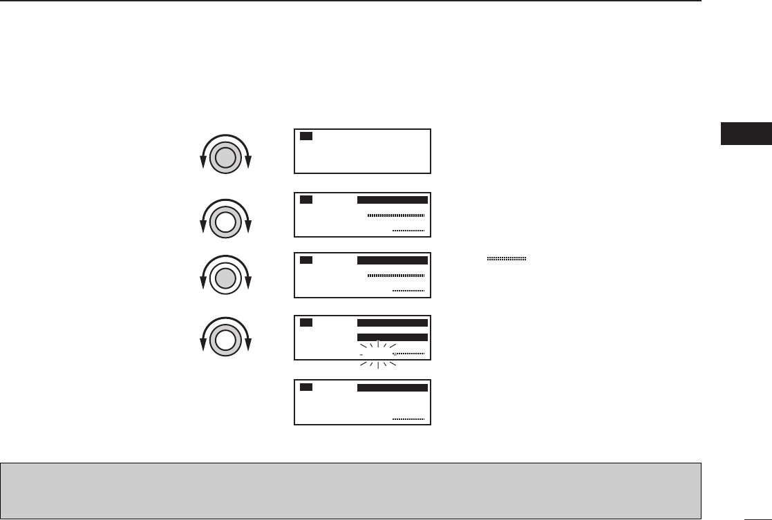
■Programming example
The following is an example showing how to program 126.000 MHz into regular memory channel 4.
“ ” appears when no frequency
has been programmed into regular
memory channel 4.
“MEMORY” and regular memory
channel number appear.
“126.00” appears in the standby
indicator.
126.005
134.80
RX
CH01
134.80
RX MEMORY
CH04
134.80
RX MEMORY
CH04
126.000
---.---
134.80
RX MEMORY
REPLACE Ç
CH04
126.005
134.80
RX MEMORY
Set a “126.000 MHz” in the
standby indicator.
q
Push [RCL], then rotate [O-
DIAL] to select “MEMORY”.
w
Push [MEM], then rotate [O-
DIAL] to select “REPLACE.”
r
Push [MEM] to store the
desired frequency into the
selected regular memory
channel.
t
Select regular memory chan-
nel 4 with [DIAL].
e
“WRITE COMPLETED” is displayed
when the selected frequency is
stored.
Regular memory channel number
blinks.
TIP: Push and hold [MEM] for 2 sec. to program a displayed frequency to any blanket memory channel automatically, after step
q.
NOTE: The programming is cancelled while all regular memory channels have already programmed.
IC-A210.qxd 2007.07.24 8:12 AM Page 11

12
3MEMORY OPERATION
■Transferring memory
contents
This function transfers a memory channel’s contents into the
active frequency indicator.
qPush [RCL] to enter the memory mode.
• The channel number appears.
• The memory channel name also appears if it has been entered.
wRotate [O-DIAL] to select the desired memory channel
type.
• Select regular, group history, weather* or GPS memory channel.
* Selectable depending on versions.
eRotate [DIAL] to select a memory channel to be trans-
ferred.
rPush [↔], then the selected memory channel is trans-
ferred into the active frequency indicator.
• The memory mode is cancelled automatically.
■Memory mode menu
(Regular and group memory
channels only)
ïREPLACE
Replacing the selected memory channel to the standby fre-
quency.
ïDELETE
Deleting the selected memory channel.
ïREVIVE
Returning the selected memory channel to its previous state.
ïCH NAME (Regular memory channel only)
Setting the channel name to the selected regular memory
channel.
ïGRP NAME (Group memory channel only)
Setting the group name to the selected memory group.
ïCH TAG (Group memory channel only)
Setting the channel tag to the selected memory channel (Se-
lecting the group memory channel is the only option).
ïDONE
Return to the memory mode.
CH01
127.005
122.00
RX MEMORY
122.005
127.00
RX MEMORY
Push [↔].
IC-A210.qxd 2007.07.24 8:12 AM Page 12

13
3
MEMORY OPERATION
03
■Regular memory channel
The transceiver has 10 regular memory channels. 5 actions
are selectable.
qPush [RCL] to enter the memory mode.
• The channel number appears.
• The memory channel name also appears if it has been entered.
wRotate [O-DIAL] to select the regular memory channel.
• “MEMORY” appears.
ePush [MEM] again, then rotate [O-DIAL] to select a menu
as follow.
• The memory channel number blinks.
rPush [MEM] to perform the selected action.
■
Group memory channel
The transceiver has 200 memory channels 200 group
channels (10 channels ×20 groups). 6 actions are selectable.
qPush [RCL] to enter the memory mode.
• The channel number appears.
• The memory channel name also appears if it has been entered.
wRotate [O-DIAL] to select the group memory channel.
• “GRP01–GRP20” appears.
ePush [DIAL], and then rotate [O-DIAL] to select the mem-
ory group from GRP01 to GRP20 if necessary.
• The group and channel numbers blink.
• Push [DIAL] again, or push [RCL] to set the memory group.
rPush [MEM] again, rotate [O-DIAL] to select a menu as
follow.
• The memory channel number blinks.
tPush [MEM] to perform the selected action.
CH01
127.005
122.00
RX GRP01
CH01
127.005
122.00
RX MEMORY
REPLACE Replace to the standby frequency.
DELETE Delete the memory channel.
REVIVE Revive the previous memory channel data.
CH NAME Edit the memory channel name.
DONE Do nothing and return to the memory mode.
REPLACE Replace to the standby frequency.
DELETE Delete the memory channel.
REVIVE Revive the previous memory channel data.
GRP NAME Edit the group name.
CH TAG Set the memory channel as a tag channel.
DONE
Do nothing and return to the memory mode.
IC-A210.qxd 2007.07.24 8:12 AM Page 13
14
3MEMORY OPERATION
■
History memory channel
The transceiver has 10 history memory channels.
The standby frequency is stored into a history memory chan-
nel when pushing [↔].
The frequency is stored into the history memory channel in
order from “CH01” to “CH10.”
qPush [RCL] to enter the memory mode.
• The channel number appears.
• The memory channel name also appears if it has been entered.
wRotate [O-DIAL] to select the history memory channel.
• “HISTORY” appears.
eRotate [DIAL] to select a desired channel.
• Push [↔]to exchange the history memory channel frequency to
the active frequency if necessary.
rPush [RCL] to exit the memory mode.
■
Clearing the memory contents
(Regular and group memory
channels only)
Unwanted memory channels can be cleared.
qPush [RCL] to select memory mode.
• The channel number appears.
• The memory channel name also appears if it has been entered.
wRotate [O-DIAL] to select the memory channel type.
• Select from regular memory channel or group memory channel.
ePush [MEM] again, then rotate [O-DIAL] to select
“DELETE.”
• The memory channel number blinks.
rPush [MEM] to delete the memory channel data.
•“-- -- -- -- -- --” appears momentarily, then the next selectable
channel appears.
tPush [RCL] to exit the memory mode.
CH01
127.005
122.00
RX HISTORY
CH01
127.000
127.000
122.00
RX MEMORY
ÅDELETE Ç
CH01
122.00
RX MEMORY
IC-A210.qxd 2007.07.24 8:12 AM Page 14

15
3
MEMORY OPERATION
03
■
Programming channel names
(Regular memory channel only)
The regular memory channel can display a 6-character name
in addition to the memory number.
qPush [RCL], then rotate [O-DIAL] to select the desired
regular memory channel in the memory mode.
• Rotate [O-DIAL] to select the memory channel type if necessary.
wPush [MEM], then rotate [O-DIAL] to select “CH NAME.”
ePush [MEM], then memory channel name’s 1st digit
blinks.
rRotate [DIAL] to select the desired character.
• The character type as shown below is selectable.
• Push [DIAL] to switch capital (A, B, C, ···) →lower case (A, B, C,
···) →number (0, 1, 2, ···) →capital (A, B, C, ···) in order.
tRotate [O-DIAL] to select the next input digit.
yRepeat r–tto input the memory channel name.
uPush [MEM] to decide the memory channel name.
• Selectable characters
■Programming group names
(Group memory channel only)
The group memory channel can display a 6-character name
in addition to the group number (“GRP01”–“GRP20”).
qPush [RCL], then rotate [O-DIAL] to select the desired
memory channel in the memory mode.
• Rotate [O-DIAL] to select the memory channel type if necessary.
wPush [DIAL], and then rotate [O-DIAL] to select the mem-
ory group from GRP01 to GRP20, if necessary.
ePush [MEM], then rotate [O-DIAL] to select “GRP NAME”.
rPush [MEM], then group name’s 1st digit blinks.
tRotate [DIAL] to select the desired character.
• The character type as shown left “Selectable characters” is se-
lectable.
• Push [DIAL] to switch capital (A, B, C, ···) →lower case (A, B, C,
···) →number (0, 1, 2, ···) →capital (A, B, C, ···) in order.
yRotate [O-DIAL] to select the next input digit.
uRepeat t–yto input the group name.
iPush [MEM] to decide the group name.
0 1 2 3 4 5 6 7 8 9 : ; < = > ? @
A B C D E F G H I J K L M N O P Q R S T U V W X Y Z [ \ ]
^ _ `
a b c d e f g h i j k l m n o p q r s t u v w x y z { | } ~ ■! ” # $
% & ’ ( ) ∗+ , – . /
IC-A210.qxd 2007.07.24 8:12 AM Page 15

16
3MEMORY OPERATION
■Programming channel tag
(Group memory channel only)
The tag name can be set a 3-character name in addition to
the group number. It is convenient for separating memory
type.
qPush [RCL], then rotate [O-DIAL] to select the desired
group memory channel in the memory mode.
• Rotate [O-DIAL] to select the memory channel type if necessary.
wPush [MEM], then rotate [O-DIAL] to select “CH TAG”
when selecting “LABEL” in “Group memory channel dis-
play” of the menu mode (p. 24)
ePush [MEM], then rotate [DIAL] to select the desired
channel tag.
• The tag type as shown below is selectable.
rPush [MEM] to decide the channel tag.
• Selectable tags
___ / TWR / GND / ATS / ATF / APP / ARR / AWS / CLR /
CTF / DEP / FSS / RFS / UNI / MF / OTH / U-1 / U-2
■
Channel tag list
TAG DISPLAY
MEANS
NAME Group*1GPS*2
_ _ _ YES – Non-tag
TWR YES YES Tower
GND YES YES Ground
ATS YES YES ATIS
ATF YES YES Air traffic
APP YES YES Approach
ARR YES YES Arrival
AWS YES YES Automatic Weather Station
CLR YES YES Clearance / Delivery
CTF YES YES
Common Traffic Advisory Frequency
DEP YES YES Departure Frequency
FSS YES YES Flight Service Station
RFS YES YES Remote Flight Service Station
UNI YES YES Unicom frequency
MF YES YES Mandatory frequency
OTH YES – Other
U-1 YES – User1 setting (Refer to p. 26)
U-2 YES – User2 setting (Refer to p. 26)
*1Group memory, *2GPS memory
CH01
127.005
122.00
RX GRP01
TWR
IC-A210.qxd 2007.07.24 8:12 AM Page 16
17
3
MEMORY OPERATION
03
■GPS memory
When connected to an external GPS receiver* equipped with
an airport frequency database, frequency data such as
nearby airports can be transferred and made available in the
GPS memory (maximum 10-memory channels).
*Ask your dealer for available GPS receiver details.
qPush [RCL] to enter the memory mode.
• The channel number appears.
wRotate [O-DIAL] to select the GPS memory channel.
• “GPS” appears.
eRotate [DIAL] to select a desired channel.
rPush [RCL] to exit the GPS memory mode.
■Weather memory channel
(U.S.A. version only)
The U.S.A. version has VHF marine WX (weather) channel
receiving capability for flight planning.
qPush [RCL] to enter the memory mode.
• The channel number appears.
wRotate [O-DIAL] to select the weather memory channel.
• “WEATHER” appears.
eRotate [DIAL] to select a desired channel.
rPush [RCL] to exit the weather memory mode.
WX01
162.555
122.00
RX DUAL WEATHER
CH01 TWR
122.055
122.00
RX GPS RJTJ
Airport code
Tag name
Channel Frequency Channel Frequency
WX01 162.550 MHz WX06 162.500 MHz
WX02 162.400 MHz WX07 162.525 MHz
WX03 162.475 MHz WX08 161.650 MHz
WX04 162.425 MHz WX09 161.775 MHz
WX05 162.450 MHz WX10 163.275 MHz
• Weather memory channel list
NOTE: See the GPS receiver’s instruction manual when
transferring the frequency data in details.
IC-A210.qxd 2007.07.24 8:12 AM Page 17

18
3MEMORY OPERATION
■GPS memory edit
The received GPS memory data is stored to desired group
memory channel.
qPush [RCL] to enter the memory mode.
• The channel number appears.
• The memory channel name also appears if it has been entered.
wRotate [O-DIAL] to select the GPS memory channel.
• “GPS” appears.
ePush [MEM] to enter the GPS memory channel edit mode,
then rotate [O-DIAL] to select the desired group memory.
• “GPS” and airport code blink.
rPush [MEM] to store the GPS memory channel data to the
selected group memory.
tPush [RCL] to exit the memory mode.
NOTE:The GPS memory data is overwritten if the setting
group memory channel has already memorized other data.
■Memory protection
The transceiver has memory protection which inhibits to the
editing (storing, deleting, replacing, etc.) of the memory group
memory channels.
Refer to “Memory Protection” (pgs. 18, 24) for details.
IC-A210.qxd 2007.07.24 8:12 AM Page 18

19
4
OTHER FUNCTIONS
03
04
■Lock function
The lock function prevents accidental frequency changes and
accidental function activation.
qPush and hold [DIAL] for 2 sec. to turn the lock function
ON.
• “ ” appears when DIAL lock mode is selected.
• “ ” appears when PANEL lock mode is selected.
wTo turn the function OFF, repeat step qabove.
• “ ” or “ ” disappears.
■Accessing 121.5 MHz
emergency frequency
The IC-A210 can be set to the 121.5 MHz emergency fre-
quency quickly. This function can be activated even when the
key lock function is in use.
qPush [EC] to call the emergency frequency to the standby
frequency, and then entering the dualwatch operation au-
tomatically.
wPush [↔]to transfer emergency frequency to the active
frequency if necessary.
• “EC” appears.
ePush [↔]to exit from the emergency frequency.
• Set the frequency except 121.500 MHz before pushing [↔]to
the standby frequency if necessary.
• “EC” disappears.
NOTE: “EC” also appears on the display while the active
frequency is set to 121.500 MHz.
O
P
O
D
O
P
O
D
NOTE: AUTOMATIC LOCK RELEASE FUNCTION
This transceiver has an “Automatic Lock Release Function”
which releases the Lock function automatically when an op-
erator gets into a panic.
The function performs when operating to push any keys (ex-
cept [EC]) 8-times or rotating any dials (except [VOL]) 25-
clicks for 5 sec.
CONVENIENT!: Push and hold [EC] for 2 sec. to enter
the direct frequency setting mode (p. 8), and set the emer-
gency frequency (121.5 MHz).
• “EC” appears.
IC-A210.qxd 2007.07.24 8:12 AM Page 19

20
4OTHER FUNCTIONS
■Intercom function
When 2-headphone and microphone jacks are connected to
the transceiver, these headsets can be used as a voice-acti-
vated intercom.
qEnter to the MENU mode.
• See p.22 for details.
wSet Intercom Usable Setting to ON.
• See p.27 for details.
eExit from the MENU mode.
• See p.22 for details.
rPush and hold [DUAL] for 2 sec. to enable the intercom
function.
• “ICS” appears.
• The headphone audio output level can be selected
“OFF,” “output level fixing (001–076)” or “interlocking with
[VOL]” in the MENU mode (p. 23).
• The microphone1 and microphone2 audio input levels
can be also selected “OFF” or “output level fixing
(001–076)” in the MENU mode (p. 23).
■Squelch test function
This function opens the squelch manually for testing.
qPush [VOL] to turn the squelch test function ON.
• “TEST” appears.
wTo turn the function OFF, repeat step qas above.
• “TEST” disappears.
IC-A210.qxd 2007.07.24 8:12 AM Page 20

21
4
OTHER FUNCTIONS
■Weather memory channel
scan (U.S.A. version only)
Scanning searches for weather channel signals automatically
and makes it easier to listen purposes.
Repeatedly scans all weather memory channels.
This function is available for the U.S.A. version only.
qSet to the weather memory channel mode.
wPush and hold [VOL] for 2 sec. to start weather memory
channel scan.
• To change the scan direction, turn [DIAL].
• “NO WTH” appears when no signal receives from WX01– WX10
channels. Then the weather memory channel scan stops auto-
matically.
• “SEARCH“ flashes while scanning.
ePush and hold [VOL] for 2 sec. again to stop the scan.
162.555
122.00
RX WEATHER
SEARCH
04
IC-A210.qxd 2007.07.24 8:12 AM Page 21
22
5MENU MODE
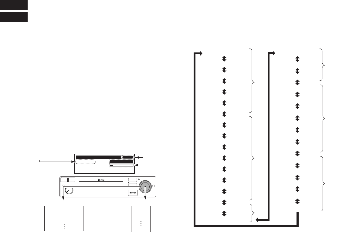
■MENU mode programming
MENU mode is available at power ON and allows you to set
seldom-changed settings. In this way you can customize
transceiver operations to suit your preferences and operating
style.
DOperating MENU mode
qRotate [VOL] to turn the transceiver’s power ON.
wPush [RCL] to set VFO mode if memory mode is selected.
ePush and hold [RCL] for 2 sec. to enter the MENU mode.
rRotate [O-DIAL] to select setting items.
tRotate [DIAL] to select the desired condition.
yPush [RCL] to exit MENU mode, and returning to the pre-
vious operating condition.
• MENU mode items
MENU MODE
HP LEVEL AF GAIN
01/31
RCL
MEM
OFF
VOL
PUSH
TEST
COMM
DUAL
EC
iA210
AF GAIN
OFF
001
076
Desired condition setting
HP LEVEL
INCOM LV1
INCOM LV2
MIC1 SQL
Menu mode items setting
Menu mode items Items number
Setting value
p. 23
HP LEVEL
GRP MEMORY
INCOM LV2
INCOM LV1
MIC1 SQL
MIC2 SQL
ANL
SQL LEVEL
FM SQL LV*
*Not available on all versions.
LOCK MODE
DW INTERVAL
MEM PROTECT
MIC2 GAIN
MIC1 GAIN
SIDETONE LV
TX MIC SEL
DISP HIGH
DISP MAN.
AUX LEVEL
DISP MODE
DISP LOW
DISP RESP.
FREQ DISP
U-1 ID SET
U-2 ID SET
AUX IN
BEEP
INCOM MODE
TIME OUT
MEM CLEAR
p. 26
p. 27
p. 25
p. 24
p. 25
IC-A210.qxd 2007.07.24 8:12 AM Page 22

23
5
MENU MODE
■MENU mode items
DHeadphone Level “HP LEVEL”
Set the headphone output level while receiving.
• AF gain : The output level is same as [VOL].
• OFF (0) : While muting the headphone.
• 001–080 : Setting audio level from 1 to 80.
DIntercom1 Microphone Audio Input Level
“INCOM LV1”
Set the intercom1 microphone input level.
• OFF (0) : While muting the intercom1 microphone.
• 001–080 : Setting the intercom1 input level from 1 to 80.
DIntercom2 Microphone Audio Input Level
“INCOM LV2”
Set the intercom2 microphone input level.
• OFF (0) : While muting the intercom2 microphone.
• 001–076 : Setting the intercom2 input level from 1 to 80.
.
DIntercom1 Squelch Level “MIC1 SQL”
Set the intercom1 squelch level.
The setting level is required to open the squelch when speak-
ing to the intercom1.
• OFF (0) : While opening the intercom1 squelch.
• 001–030 : Setting the intercom1 squelch level from 1 to 30.
DIntercom2 Squelch Level “MIC2 SQL”
Set the intercom2 squelch level.
The setting level is required to open the squelch when speak-
ing to the intercom2.
• OFF (0) : While opening the intercom2 squelch.
• 001–030 : Setting the intercom2 squelch level from 1 to 30.
DAutomatic Noise Limiter “ANL”
The ANL (Automatic Noise Limiter) function reduces noise
components such as that caused by engine ignition systems
while receiving.
• OFF : The ANL function is OFF.
• ON : The ANL function is ON.
05
IC-A210.qxd 2007.07.24 8:12 AM Page 23

24
5MENU MODE
■MENU mode items (Continued)
DAM Squelch Level “SQL LEVEL”
Set the squelch level for AM mode operation.
In order to receive signals properly, as well as for the scan to
function effectively, the squelch must be adjusted to the
proper level.
• –010–010 : Setting AM squelch level from –10 to 10.
DFM Squelch Level “FM SQL LV”
(U.S.A. version only)
Set the squelch level for FM mode operation.
• –010–010 : Setting FM squelch level from –10 to 10.
DLock Mode “LOCK MODE”
Set the lock function effective area.
• OFF : The lock function is nonfunctional.
• DIAL : The lock function applies to [DIAL].
• PANEL : The lock function applies to buttons on the front panel.
DDualwatch Interval “DW INTERVAL”
Set the interval time while operating dualwatch or weather
scan.
• FAST : The interval time sets to 300 msec.
• MID : The interval time sets to 600 msec.
• SLOW : The interval time sets to 2 sec.
.
DMemory Protection “MEM PROTECT”
Set the memory protection to regular memory channels and
group memory channels.
Editing the regular memory and group memory channels is
inhibited while the protection is ON.
• OFF : The memory protection is OFF.
• ON : The memory protection is ON.
DGroup Memory Channel Display
“GRP MEMORY”
Set the displaying whether the label displays or not.
• CH : The only channel number is displayed.
• LABEL : The label is also displayed.
DMicrophone1 Gain “MIC1 GAIN”
Set the microphone1’s gain.
• –010–010 : Setting the microphone1’s gain from –10 to 10.
DMicrophone2 Gain “MIC2 GAIN”
Set the microphone2’s gain.
• –010–010 : Setting the microphone2’s gain from –10 to 10.
IC-A210.qxd 2007.07.24 8:12 AM Page 24

25
5
MENU MODE
■MENU mode items (Continued)
DSidetone Level “SIDETONE LV”
When using an optional headset (supplied from 3rd party*)
via the adapter, the transceiver outputs your transmitted voice
to the headset for monitoring.
*Ask your dealer in details.
• OFF (0) : The sidetone function is OFF.
• 001–080 : Setting sidetone level from 1 to 80.
DTransmitting Microphone Selection
“TX MIC SEL”
Set the usable microphone when pushing microphone’s PTT
switch.
The item allows you to control which connected microphone
is permitted to transmit.
• MIC1 : Selecting the microphone1.
• MIC2 : Selecting the microphone2.
• MIC1+2 : Selecting both the microphone1 and microphone2.
DDimmer Mode “DISP MODE”
Set the OLED dimmer mode.
• OFF : The dimmer function is OFF.
• AUTO : Set the dimmer automatically depending on local bright-
ness.
The light sensor which built-in the display is used for
this function.
• MANUAL : Set the dimmer depending on Dimmer Brightness (Low)
“DISP LOW”.
DDimmer Brightness (Low) “DISP LOW”
Set the lower brightness level in the automatic adjustment
range when “AUTO” is selected at the “Dimmer Mode.”
The transceiver automatically adjusts its display brightness
by the current lighting conditions.
• OFF : The key backlight sets OFF.
• 001–049 : Setting low dimmer brightness level from 1 to 49.
DDimmer Brightness (High) “DISP HIGH”
Set the upper brightness level in the automatic adjustment
range when “AUTO” is selected at the Dimmer Mode.
• 050–100 : Setting dimmer brightness level from 50 to 100.
05
IC-A210.qxd 2007.07.24 8:12 AM Page 25

26
5MENU MODE
■MENU mode items (Continued)
DDimmer Brightness (Manually) “DISP MAN.”
Set the brightness manually to suit your own preferences.
• 0–100 : Setting dimmer level manually from 0 (OFF) to 100.
DDimmer Response “DISP RESP.”
Set the dimmer switching speed when selecting “AUTO” at
the “Dimmer Mode.”
• STANDARD
: Selecting switch speed is normal.
• FAST : Selecting switch speed is fast.
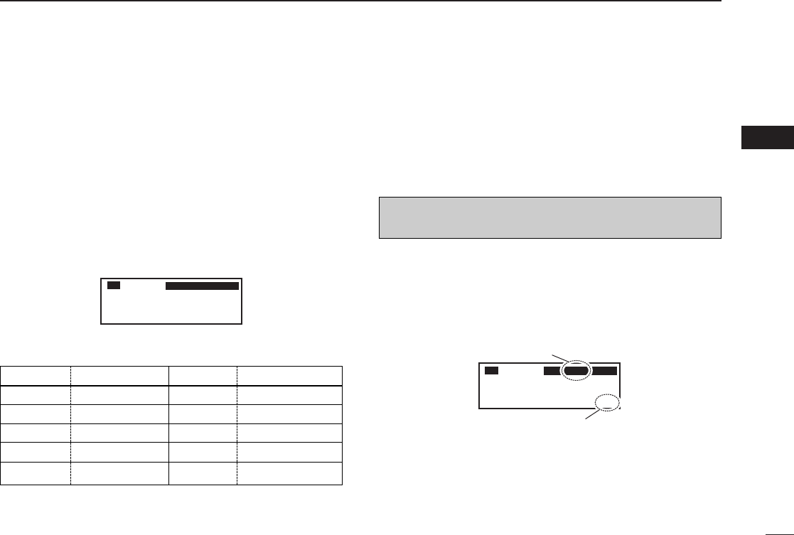
DFrequency Display “FREQ DISP”
Set the 1 kHz digit frequency displaying to the OLED.
• OFF : The 1 kHz digit always does not display on the OLED.
• ON : The 1 kHz digit always display on the OLED.
• ZERO SUPP.
: The 1 kHz digit display on the OLED (Except the digit
is 0).
DUSER-1 Setting “U-1 ID SET”
Set the USER-1, channel tag, to the desired ID.
qPush [MEM] to enter the U-1 ID edit mode.
wRotate [DIAL] to select the desired character.
eRotate [O-DIAL] to select the next input digit.
rRepeat w–eto input the U-1 ID.
tPush [MEM] again to store the U-1 ID, and exit the edit mode.
DUSER-2 Setting “U-2 ID SET”
Set the USER-2, channel tag, to the desired ID.
qPush [MEM] to enter the U-2 ID edit mode.
wRotate [DIAL] to select the desired character.
eRotate [O-DIAL] to select the next input digit.
rRepeat w–eto input the U-2 ID.
tPush [MEM] again to store the U-2 ID, and exit the edit mode.
DExternal Input “AUX IN”
Set the external input mode.
• OFF : The external input does not use.
• ON : The external input is available while squelch is closing.
• INCOM : The external input is available with the intercom opera-
tions as following.
- The intercom function is OFF.
- While the intercom function does not use.
- While audio signal does not input to the intercom’s mi-
crophone.
IC-A210.qxd 2007.07.24 8:12 AM Page 26

27
5
MENU MODE
■MENU mode items (Continued)
DExternal Input Level “AUX LEVEL”
Set the external input level.
• OFF (0) : The external input does not operate.
• 001–080 : Setting the external input level from 1 to 80.
• AF GAIN : Interlocking with [VOL].
DBeep Tone Level “BEEP”
Confirmation beep tones normally sound when storing mem-
ory, operating time-out-timer function, etc. These can be set
the desired beep level as you prefer.
• OFF (0) : The beep tone turns OFF.
• 001–100 : Setting the beep tone level from 1 to 100.
DIntercom Usable Setting “INCOM MODE”
Set the intercom using or not.
• ON : The intercom is usable.
• OFF : The intercom is unusable.
DTime-Out-Timer “TIME OUT”
To prevent accidental prolonged transmission, etc., the trans-
ceiver has a time-out-timer function. This timer starts when a
transmission begins, and will cut off the transmission when
the time set in the timer elapses.
• 020–240 : Setting time-out-timer starting period from 20 sec. to
240 sec. at 10 sec. intervals.
DMemory Clear “MEM CLEAR”
Setting values in the CPU are cleared.
Push and hold [MEM] for 2 sec., the CPU is reset as follow.
• MENU : MENU mode items are reset.
• MEMORY : Stored memories are reset.
• ALL : All CPU data is reset. 05
IC-A210.qxd 2007.07.24 8:12 AM Page 27
28
6INSTALLATION AND REMOVAL
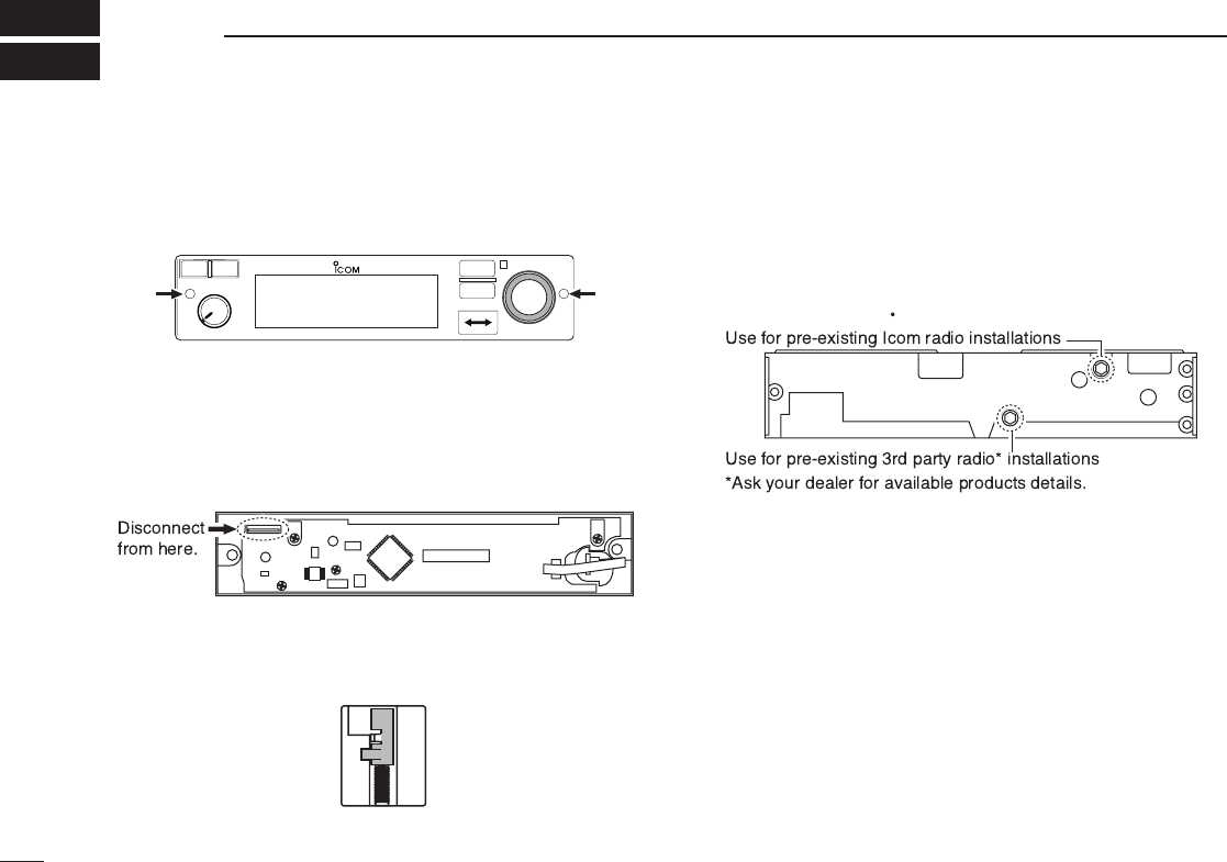
■Transceiver installation
qInsert a
3
/
32
in allen wrench into the 2-holes in the front
panel.
wTurn the wrench counterclockwise until the front panel is
loose.
• A cable connects the front panel with the main unit.
eDisconnect the flat cable from the front panel’s connector
to remove the front panel.
rVisually confirm that the metal catches on the top and bot-
tom of the transceiver are as shown below.
tTurn the wrench clockwise until the main unit is fixed to the
installation rack.
• Turn the wrench in the upper socket as shown below when using
the installation rack for Icom products.
• Turn the wrench when in the lower socket as shown below when
using the installation rack for 3rd party* products.
yReplace the disconnected cable and removed front panel
in place.
■
Transceiver removal
The IC-A210 may easily be removed from the installation
rack, if desired.
qPerform the same steps as q–eof “Transceiver installa-
tion” to remove the front panel (See the left column).
wTurn the wrench counterclockwise until the main unit
moves slightly from the installation rack.
• See tof “Transceiver installation” for details.
ePull out the transceiver slowly from the installation rack.
RCL
MEM
OFF
VOL
PUSH
TEST
COMM
DUAL
EC
iA210
• Front panel rear view
• Main unit top/bottom view
Main unit front view
IC-A210.qxd 2007.07.24 8:12 AM Page 28

29
7
CLONING
DData cloning
Cloning allows you to quickly and easily transfer the
programmed contents or data from a PC to a transceiver
using the optional CS-A210 CLONING SOFTWARE.
Data can be cloned to and from a PC (IBM compatible) using
the optional CS-A210 CLONING SOFTWARE and the optional OPC-
1529R CLONING CABLE. Consult the CS-A210 instruction manual
and HELP message in details.
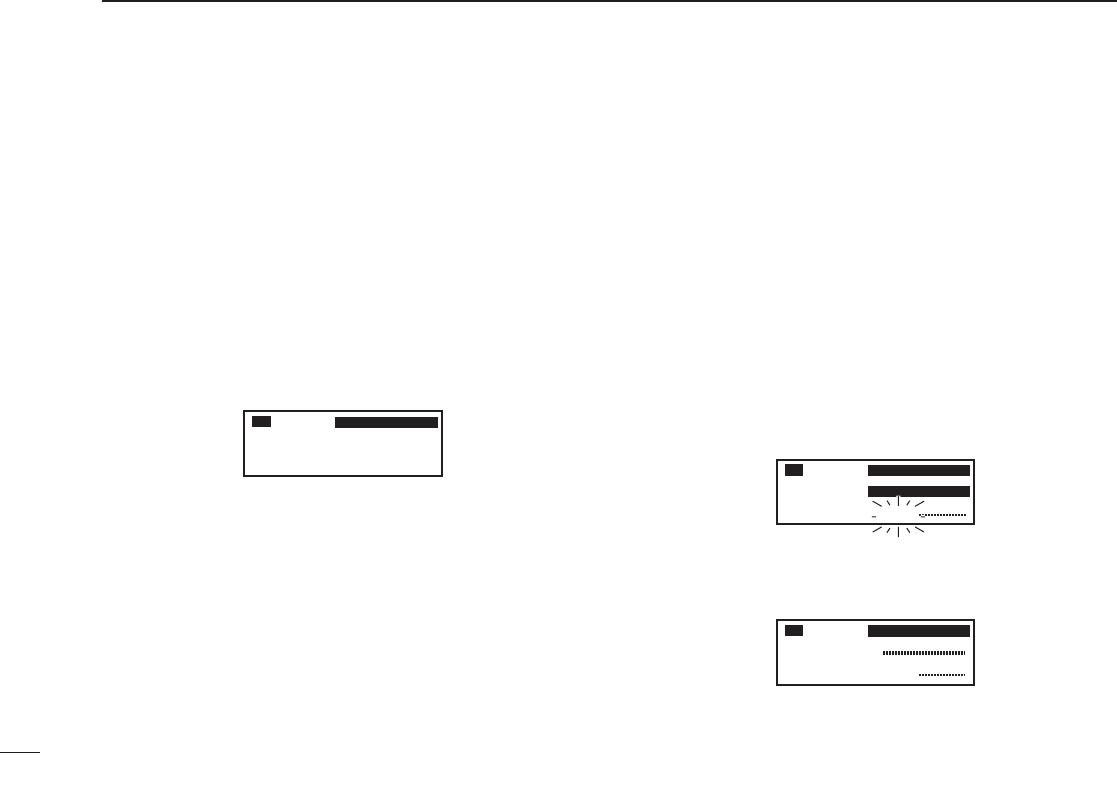
DDisplayed Message
• While clone writing.
• When clone writing is finished properly.
• When clone writing error occurs.
• While clone reading.
• When turn the power OFF/ON after clone writing error oc-
curs.
(The transceiver boots with Error mode.)
In this case, Clone writing correctly data to the transceiver is
necessary to cancel the error.
CLONE
WRITE
CLONE
WRITE OK
CLONE
WRITE ERR
CLONE
READ
127.00
RX MEMORY
CLONE
NO DATA
06
07
IC-A210.qxd 2007.07.24 8:12 AM Page 29

30
8SPECIFICATIONS
DGeneral
• Frequency range : 118.000 to 136.975 MHz
161.650 to 163.275 MHz*
• Channel spacing : 25 kHz
• Frequency stability : ±5 ppm
• Operating temperature : –20˚C to +55˚C
–4˚F to +131˚F
• Antenna impedance : 50 Ω
• Number of memory channels : 10 memory channels
200 group channels
10 history channels
10 GPS channels
10 weather channels*
• Mode : AM (6K00A3E)
•Power supply requirement : 13.80 V / 27.50 V DC
(negative ground)
•Dimensions : 160 (W)✕34 (H)✕271 (D) mm
(projections not incl.)
6
5
/
16
(W)✕1
11
/
32
(H)✕10
21
/
32
(D)
in
• Weight : approx 1.0 kg; 2.2 lb
*U.S.A. version only, receiving only.
DTransmitter
• Mode : A3E
• Output power : 8 W (Carrier power)
• Spurious emissions : –60 dBc
• Microphone impedance : 600 Ω
• Modulation limiting : 70% (Max 98%)
DReceiver
• Receive system : Double conversion
superheterodyne
• Intermediate frequencies : 1st 38.85 MHz
2nd 450 kHz
•Sensitivity : (AM) Less than 2 µV (pd)
at 6 dB S/N
(FM) Less than 1.4 µV
at 12 dB SINAD*
• Selectivity : 6 dB ±3 kHz
60 dB ±22 kHz
• Spurious response rejc. : More than 74 dBµ
• Audio output power : 5 W with a 4 Ωload (External
speaker)
60 mW with a 500 Ωload
(Headphone)
Measurements made in accordance with RTCA DO-186B for
U.S.A. version. All stated specifications are subject to change
without notice or obligation.
IC-A210.qxd 2007.07.24 8:12 AM Page 30
31
9
OPTIONS
DCS-A210
CLONING SOFTWARE
Provides quick and easy programming of items, including pri-
vate channels, scan settings, etc., via an Windows®PC (Mi-
crosoft®Windows®2000/Me/XP/Vista™) to transceiver.
DOPC-1529R
CLONING CABLE
This cloning cable provides convenient connection to a PC to
access programmable features, such as memory channels,
memory name, etc.
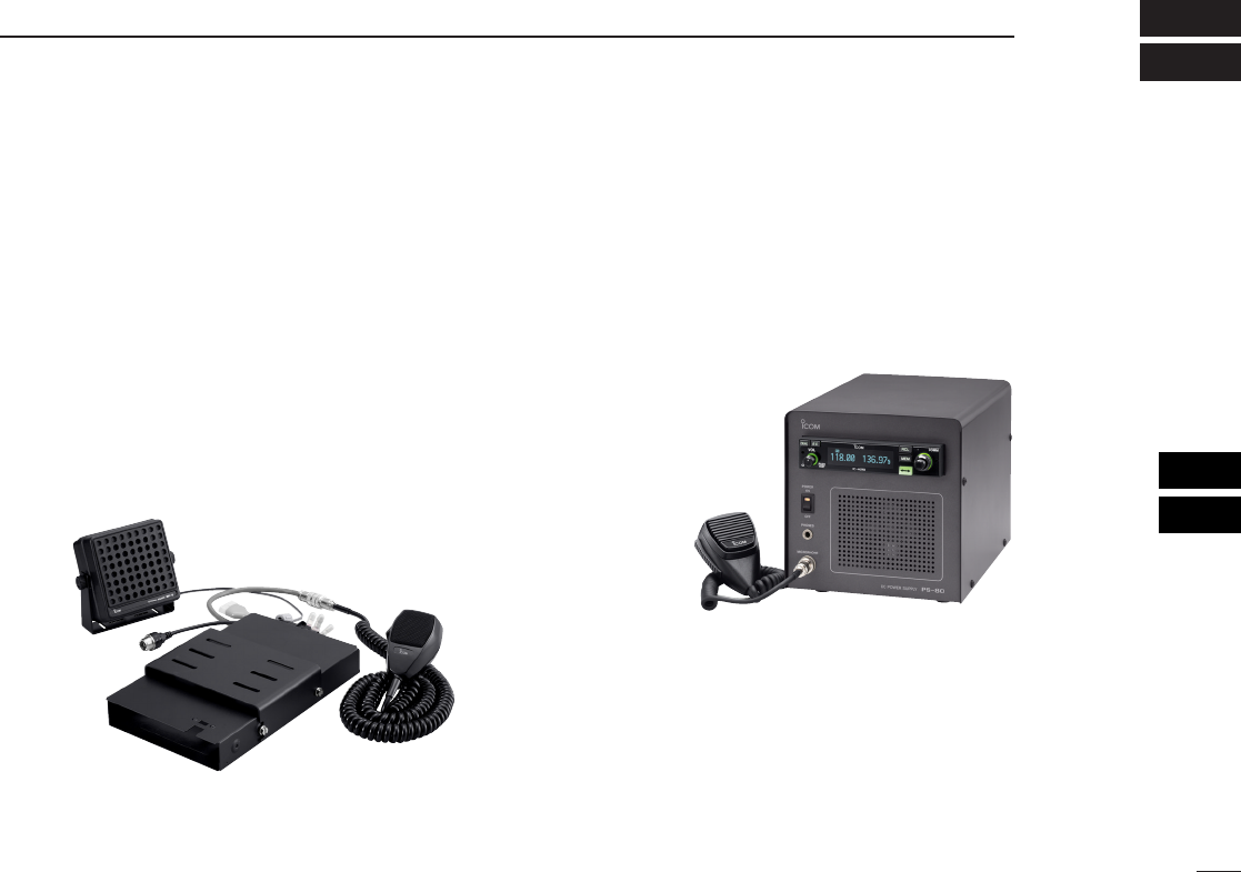
DMB-53
MOUNTING BRACKET
For mounting the transceiver to a vehicle. The external
speaker and microphone are included.
DPS-80
POWER SUPPLY
Provides convenient operation of the transceiver on the
ground. A built-in speaker and microphone* are included.
*Depending on version.
NOTE: PS-80’s specifications
Dimensions : 200 (W) ×200 (H) ×300 (D) mm
7.9 (W) ×7.9 (H) ×11.8 (D) in
Outputs : 13.8 V DC / 6 A
08
09
IC-A210.qxd 2007.07.24 8:12 AM Page 31

32
INDEX
A
Accessing 121.5 MHz emergency frequency.........................................19
AM squelch level....................................................................................24
Automatic noise limiter...........................................................................23
B
Basic operation ........................................................................................5
Beep tone level ......................................................................................27
Blank channel...........................................................................................9
C
Channel selection...................................................................................10
Channel tag list ......................................................................................16
Clearing the memory contents ...............................................................14
Cloning...................................................................................................29
D
Data cloning ..........................................................................................29
Dimmer brightness (High) ......................................................................25
Dimmer brightness (Low).......................................................................25
Dimmer brightness (Manually) ...............................................................26
Dimmer mode ........................................................................................25
Dimmer response...................................................................................26
Direct frequency selection........................................................................5
Direct frequency setting mode operation .................................................8
Displayed message................................................................................29
Dualwatch interval..................................................................................24
Dualwatch operation ................................................................................8
E
Emergency frequency ............................................................................19
Entering memory mode............................................................................9
External input .........................................................................................26
External input level.................................................................................27
F
FM squelch level ....................................................................................24
Frequency display..................................................................................26
Frequency exchanging/not exchanging ...................................................6
Frequency selection.................................................................................5
Frequency set example............................................................................7
Frequency step ......................................................................................27
Front panel...............................................................................................1
Function display .......................................................................................4
G
General frequency selection ....................................................................5
GPS memory..........................................................................................17
GPS memory channel..............................................................................9
GPS memory edit...................................................................................18
Group memory channel......................................................................9, 13
Group memory channel display .............................................................24
H
Headphone level ....................................................................................23
History memory channel ....................................................................9, 14
I
Installation and removal .........................................................................28
Intercom function....................................................................................20
Intercom usable setting..........................................................................27
Intercom1 Microphone audio input level ................................................23
Intercom1 squelch level .........................................................................23
Intercom2 Microphone audio input level ................................................23
Intercom2 squelch level .........................................................................23
L
Lock function..........................................................................................19
Lock mode..............................................................................................24
M
Memory channel type...............................................................................9
Memory clear .........................................................................................27
Memory mode menu ..............................................................................12
IC-A210.qxd 2007.07.24 8:12 AM Page 32

33
INDEX
Memory operation ....................................................................................9
Memory protect function...........................................................................9
Memory protection ...........................................................................18, 24
Menu mode items...................................................................................23
Menu mode programming......................................................................22
Microphone1 gain ..................................................................................24
Microphone2 gain ..................................................................................24
O
Operating menu mode ...........................................................................22
Other functions.......................................................................................19
P
Panel descriptions....................................................................................1
Programming channel names ................................................................15
Programming channel tag......................................................................16
Programming example ...........................................................................11
Programming group names....................................................................15
Programming notes..................................................................................9
Programming a memory channel...........................................................10
R
Regular memory channel...................................................................9, 13
S
Safety training information .....................................................................35
Sidetone level .......................................................................................25
Squelch test function..............................................................................20
Standby frequency selection....................................................................5
T
Time-Out-Timer ......................................................................................27
Transceiver installation ..........................................................................28
Transceiver removal...............................................................................28
Transferring memory contents ...............................................................12
Transmitting .............................................................................................6
Transmitting microphone selection .......................................................25
U
USER-1 setting ......................................................................................26
USER-2 setting ......................................................................................26
W
Weather memory channel..................................................................9, 17
Weather memory channel scan .............................................................21
IC-A210.qxd 2007.07.24 8:12 AM Page 33

34
M E M O
IC-A210.qxd 2007.07.24 8:12 AM Page 34

35
10
SAFETY TRAINING INFORMATION
Your Icom radio generates RF electromag-
netic energy during transmit mode. This
radio is designed for and classified as “Oc-
cupational Use Only”, meaning it must be
used only during the course of employment
by individuals aware of the hazards, and the
ways to minimize such hazards. This radio
is NOT intended for use by the “General
Population” in an uncontrolled environment.
• For compliance with FCC and Industry Canada RF Expo-
sure Requirements, the transmitter antenna installation shall
comply with the following two conditions:
1. The transmitter antenna gain shall not exceed 0 dBi.
2. The antenna is required to be located outside of a vehicle
and kept at a distance of 36 centimeters or more between
the transmitting antenna of this device and any persons
during operation. For a small vehicle, the antenna as
worst case, the antenna shall be located on the roof top
at any place on the centre line along the vehicle in order
to achieve 36 centimeters separation distance. In order
to ensure this distance is met, the installation of the an-
tenna must be mounted at least 36 centimeters away
from the nearest edge of the vehicle in order to protect
against exposure to bystanders.
To ensure that your exposure to RF elec-
tromagnetic energy is within the FCC al-
lowable limits for occupational use, always
adhere to the following guidelines:
•DO NOT operate the radio without a proper antenna at-
tached, as this may damage the radio and may also cause
you to exceed FCC RF exposure limits. A proper antenna is
the antenna supplied with this radio by the manufacturer or
an antenna specifically authorized by the manufacturer for
use with this radio.
•DO NOT transmit for more than 50% of total radio use time
(“50% duty cycle”). Transmitting more than 50% of the time
can cause FCC RF exposure compliance requirements to
be exceeded. The radio is transmitting when the “TX indica-
tor” appears. You can cause the radio to transmit by press-
ing the “PTT” switch.
Electromagnetic Interference/Compatibility
During transmissions, your Icom radio generates RF energy
that can possibly cause interference with other devices or
systems. To avoid such interference, turn off the radio in
areas where signs are posted to do so. DO NOT operate the
transmitter in areas that are sensitive to electromagnetic ra-
diation such as hospitals, aircraft, and blasting sites.
10
IC-A210.qxd 2007.07.24 8:13 AM Page 35

A-6602H-1EX
Printed in Japan
©2007 Icom Inc.
Printed on recycled paper with soy ink. 1-1-32 Kamiminami, Hirano-ku, Osaka 547-0003, Japan
IC-A210.qxd 2007.07.24 8:13 AM Page 36