ICOM orporated 297400 VHF Air Band Transceiver User Manual IC A210 INSTRUCTION MANUAL Draft version
ICOM Incorporated VHF Air Band Transceiver IC A210 INSTRUCTION MANUAL Draft version
Contents
- 1. Manual Revised
- 2. User Manual
User Manual
iA210
VHF AIR BAND TRANSCEIVER
INSTRUCTION MANUAL
This device complies with Part 15 of the FCC
Rules. Operation is subject to the condition that
this device does not cause harmful interference.

i
IMPORTANT
READ ALL INSTRUCTIONS carefully and completely
before using the transceiver.
SAVE THIS INSTRUCTION MANUAL — This in-
struction manual contains important operating instructions
for the IC-A210.
EXPLICIT DEFINITIONS
The explicit definitions below apply to this instruction man-
ual.
WORD
RWARNING!
CAUTION
NOTE
DEFINITION
Personal injury, fire hazard or electric shock
may occur.
Equipment damage may occur.
If disregarded, inconvenience only. No risk
of personal injury, fire or electric shock.
FEATURES
❍ Large, bright OLED display
A fixed mount VHF airband first, the IC-A210 has an organic light
emitting diode (OLED) display. The all man-made lighting emits its
own light and the display offers many advantages in brightness,
vividness, high contrast, wide viewing angle and response time
compared to a conventional display. In addition, the auto dimmer
function can adjust the display for optimum brightness, during day or
night.
❍ Easy channel selection
It’s fast and easy to select any of the memory channels in the
IC-A210. The “flip-flop” arrow button switches between active and
standby channels. The DualWatch function allows you to monitor
two channels simultaneously. In addition, the history memory chan-
nel stores the last 10 channels used and allows you to recall those
channels easily.
❍ GPS memory function
When connected to an external GPS receiver* equipped with an air-
port frequency database, the IC-A210 will instantly tune in the local
airport frequency as you fly into its airspace.
*Ask your dealer for available GPS receiver details.
❍ 13.8 V/27.5 V DC power source
The built-in DC-DC converter accepts a 13.8 or 27.5 V DC power
source. The IC-A210 is easily installed in most airplanes or vehicles.
❍ Intercom function
The IC-A210 has a built-in voice activated intercom function allowing
the pilot to talk with a co-pilot, or other person, via headsets. The IC-
A210 has adjustable audio level and squelch control functions.
For Canada:
This device complies with RSS-310 of Industry Canada. Operation is subject
to the condition that this device does not cause harmful interference.
Cet appareil est conforme au CNR-310 d’Industrie Canada. Son exploitation
est autorisée sous réserve que l’appareil ne cause pas de brouillage préjudi-
ciable.

DO NOT place unit in a non-secure place to avoid inad-
vertent use by children.
DO NOT push the PTT when not actually intending to
transmit.
DO NOT use or place the transceiver in direct sunlight or
in areas with temperatures below –20°C (–4°F) or above
+55°C (+131°F).
DO NOT place the transceiver in excessively dusty envi-
ronments.
DO NOT place the transceiver against walls. This will ob-
struct heat dissipation.
DO NOT use chemical agents such as benzine or alcohol
when cleaning, as they damage the transceiver surfaces.
BE CAREFUL! The transceiver will become hot when
operating continuously for long periods.
PRECAUTIONS
ii
R WARNING! NEVER operate the transceiver with
a headset or other audio accessories at high volume levels.
Hearing experts advise against continuous high volume op-
eration. If you experience a ringing in your ears, reduce the
volume level or discontinue use.
R WARNING! NEVER connect the transceiver to an
AC outlet or to a power source of more than 28 V DC. Such
a connection will damage the transceiver.
CAUTION: NEVER connect the transceiver to a
power source that is DC fused at more than 10 A. Accidental
reverse connection will be protected by this fuse, higher fuse
values will not give any protection against such accidents
and the transceiver will be damaged.
DO NOT operate the transceiver near unshielded electri-
cal blasting caps or in an explosive atmosphere.
DO NOT connect the transceiver to a power source using
reverse polarity. This connection will not only blow fuses but
also may damage the transceiver. FCC caution: Changes or modifications to this transceiver,
not expressly approved by Icom Inc., could void your authority
to operate this transceiver under FCC regulations.

iii
IMPORTANT ······························································································i
EXPLICIT DEFINITIONS ···········································································i
FEATURES ································································································i
PRECAUTIONS ························································································ii
TABLE OF CONTENTS ··········································································· iii
1 PANEL DESCRIPTION ·········································································1
■ Front panel ························································································1
■ Rear panel ·························································································3
■ Main unit ····························································································3
■ Function display ················································································4
2 BASIC OPERATION ·············································································5
■ Frequency selection ··········································································5
■ Standby frequency selection (Step 1-2) ············································5
■ Frequency exchanging (Step 2-2) ·····················································6
■ Receiving···························································································6
■ Transmitting ·······················································································6
■ Frequency setting example ·······························································7
■ Direct frequency setting mode operation ···········································8
■ DualWatch operation ·········································································8
3 MEMORY OPERATION ········································································9
■ Programming notes ···········································································9
■ Entering memory mode ·····································································9
■ Memory channel type ········································································9
■ Channel selection ············································································10
■ Programming a memory channel ····················································10
■ Programming example ····································································11
■ Transferring memory contents ·························································12
■ Memory mode menu
( Regular and group memory channels only) ···································12
■ Regular memory channel ································································13
■ Group memory channel ···································································13
■ History memory channel ·································································14
■ Clearing the memory contents
( Regular and group memory channels only) ···································14
■ Programming channel names (Regular memory channel only) ······15
■ Programming group names (Group memory channel only) ············15
■ Programming channel tag (Group memory channel only)···············16
■ Channel tag list················································································16
■ Weather memory channel (U.S.A. version only) ······························17
■ GPS memory ···················································································17
■ GPS memory edit ············································································18
■ Memory protection ··········································································18
4 OTHER FUNCTIONS ··········································································19
■ Lock function ···················································································19
■ Accessing 121.5 MHz emergency frequency ··································19
■ Intercom function ·············································································20
■ Squelch test function ·······································································20
■ Frequency step setting ····································································20
■ Weather memory channel scan (U.S.A. version only) ·····················21
5 MENU MODE ······················································································22
■ MENU mode programming ······························································22
■ MENU mode items ··········································································23
6 CLONING ····························································································28
7 OPTIONS ····························································································29
8 SPECIFICATIONS ··············································································30
9 SAFETY TRAINING INFORMATION ··················································32
10 FOR CLASS B UNINTENTIONAL RADIATORS ······························34
TABLE OF CONTENTS
Icom, Icom Inc. and the Icom logo are registered trademarks of Icom Incor-
porated (Japan) in Japan, the United States, the United Kingdom, Germany,
France, Spain, Russia and/or other countries.
IBM is a registered trademark of International Business Machines.
Microsoft, Windows and Windows Vista are registered trademarks of Microsoft
Corporation in the United States and/or other countries.
1
1
PANEL DESCRIPTION
01
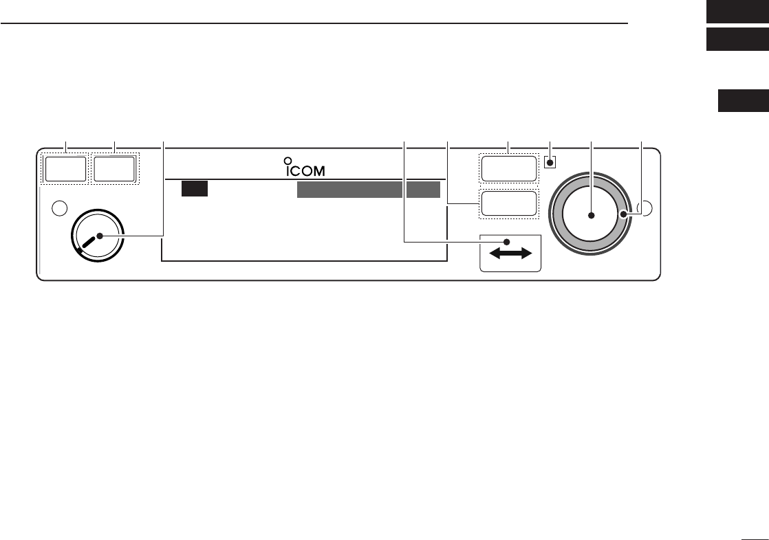
■ Front panel
q DUAL SWITCH [DUAL]
➥ Push to turn DualWatch operation ON or OFF (p. 8).
➥ Hold down for 2 seconds to turn the intercom function
ON or OFF.
w EMERGENCY CHANNEL SWITCH [EC]
➥ Push to set the emergency frequency (121.5 MHz) as
the standby frequency (p. 19).
➥ Hold down for 2 seconds to enter the direct frequency
setting mode (p. 8), and set the emergency frequency
(121.5 MHz) (p. 19).
e VOLUME/POWER SWITCH [VOL]
➥ Turn [VOL] to switch the power ON or OFF (p. 5).
➥ Adjusts the audio output level.
The volume level bar appears while rotating [VOL].
➥ Push to set the squelch test function ON or OFF
(p. 20).
➥ Hold down for 2 seconds to start the weather channel
(U.S.A. version only) scan (p. 21).
r FREQUENCY EXCHANGE (FLIP-FLOP) SWITCH [↔]
➥ Push to exchange the standby frequency with the ac-
tive frequency (p. 6).
➥ Hold down for 2 seconds to enter direct frequency set-
ting mode (p. 8).
RCL
MEM
OFF
VOL
PUSH
TEST
COMM
DUAL
EC
iA210
CH09 SAMPLE
121.525
118.00
RX MEMORY
eytriouqw
2
1PANEL DESCRIPTION
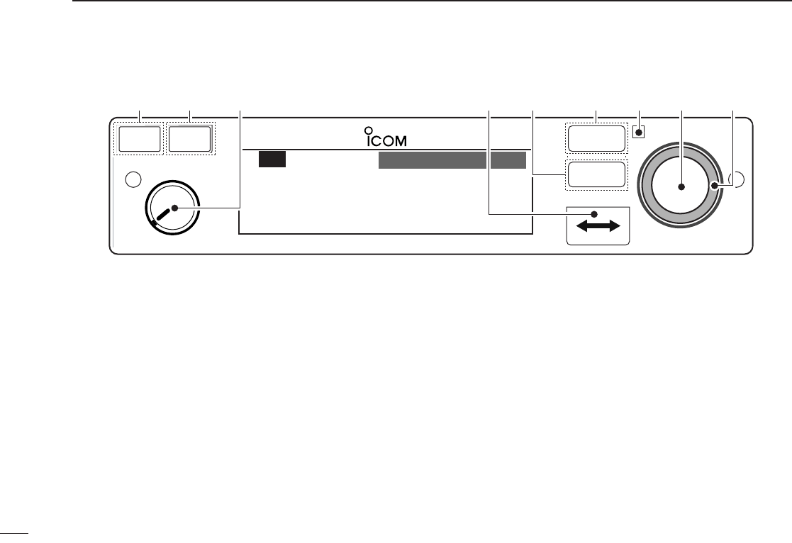
■ Front panel (Continued)
t MEMORY SWITCH [MEM]
Hold down for 2 seconds to program a displayed fre-
quency to any blank regular memory channel or delete/
revive the selected memory channel (depending on the
operating mode) (p. 9).
y RECALL SWITCH [RCL]
➥ Push to enter/exit the memory mode (p. 9).
➥ Hold down for 2 seconds to enter the menu mode
(p. 22).
u LIGHT-SENSITIVE DETECTOR
This detector senses ambient light. The detector is used
to adjust “Dimmer brightness (Low/High)” (p. 25) auto-
matically when the “Dimmer Mode” (p. 25) is set to ‘AUTO.’
i INNER (Small) TUNING DIAL [DIAL]
➥ Rotate to set the standby frequencies (kHz digit)
(p. 5), memory channels (p. 10), MENU mode settings
(p. 22).
➥ Hold down for 2 seconds to turn the dial/panel lock
function ON (p. 19).
o OUTER (Large) TUNING DIAL [O-DIAL]
➥ Rotate to set the standby frequency (MHz digit) (p. 5),
group memory channel (p. 13), cursor position (p. 15),
etc.
➥ Rotate to change the scan direction while scanning
(p. 21).
RCL
MEM
OFF
VOL
PUSH
TEST
COMM
DUAL
EC
iA210
CH09 SAMPLE
121.525
118.00
RX MEMORY
eytriouqw
3
1
PANEL DESCRIPTION
01
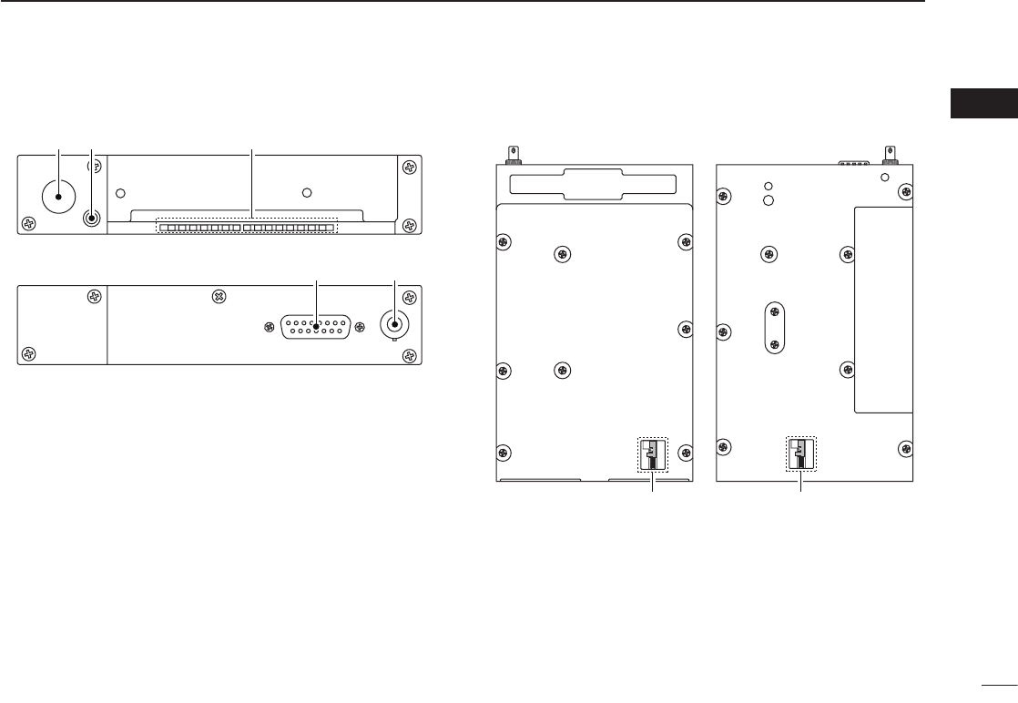
■ Rear panel
q ANTENNA CONNECTOR
Connect an antenna connector.
w CLONING JACK
Connect an optional cloning cable (OPC-1529R). Refer to
page 28 for details.
e DC, MICROPHONE, SPEAKER, HEADPHONE AND
DATA JACK
Connect a 13.8 V or 27.5 V DC power supply, speaker,
headphone and third party GPS receiver*1.
Refer to the “INSTALLATION GUIDE” for details.
*
1Ask your dealer for available GPS receiver details.
■ Main unit
q Metal catch (For Icom products)
Use to attach to an installation rack for Icom products.
Refer to the “INSTALLATION GUIDE” for details.
w Metal catch (For third party products*)
Use to attach to an installation rack for third party prod-
ucts*.
*Ask your dealer for available products details.
q w
e q
e
For PS-80 type
For the third party* compatible type (MB-113)
NOTE: Supplied with some transceiver’s versions.
*Ask your dealer for available products details.
• Top view• Bottom view
q w
4
1PANEL DESCRIPTION
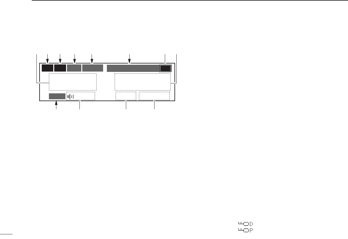
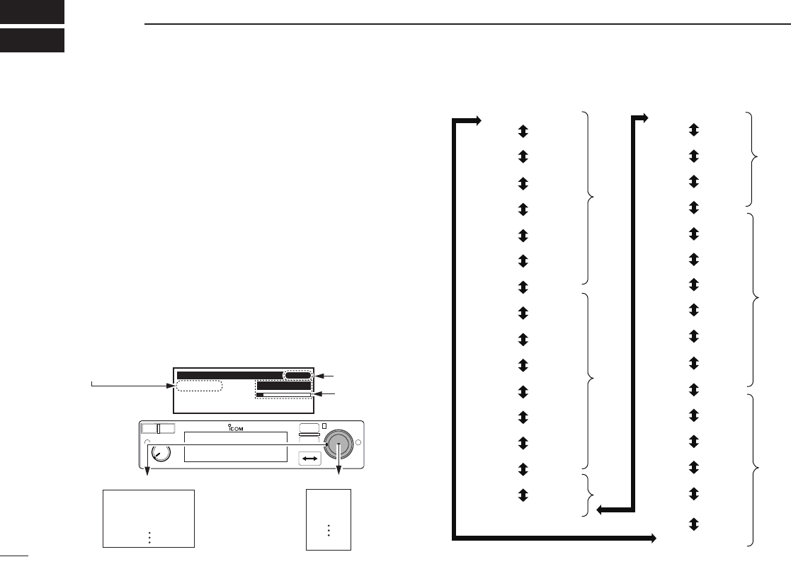
■ Function display
q ACTIVE FREQUENCY INDICATOR
➥ Shows the active frequency (p. 6).
➥ Shows the MENU mode items in the MENU mode
(p. 22).
w TX INDICATOR
Appears while transmitting (p. 6).
e RX INDICATOR
➥ Appears when receiving a signal on the active fre-
quency signal (p. 6).
➥ Appears when receiving a signal on the standby fre-
quency signal during DualWatch operation (p. 8).
➥ Appears when opening the active frequency’s squelch
function (p. 6).
r INTERCOM INDICATOR
Appears when the intercom function is in use (p. 20).
t DUALWATCH INDICATOR
Appears when the DualWatch function is active (p. 8).
y MEMORY CONDITION INDICATOR
➥ Indicates “MEMORY” when the regular memory chan-
nel is selected (p. 13).
➥ Indicates “GRP01–GRP20” when the group memory
channel is selected (p. 13).
The group name is also indicated if the name has been
entered.
➥ Indicates “HISTORY” when the history memory chan-
nel is selected (p. 14).
➥ Indicates “WEATHER” when the weather memory
channel is selected (U.S.A. version only) (p. 17).
➥ Indicates “GPS” when the GPS memory channel is se-
lected (The third party GPS receiver is required) (p. 17).
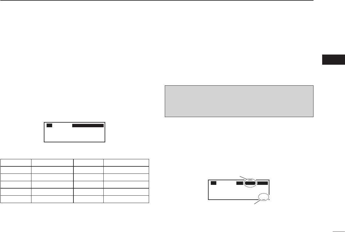
u STANDBY FREQUENCY INDICATOR
➥ Shows the standby frequency (p. 5).
➥ Shows the setting values in the MENU mode (p. 22).
i CHANNEL NAME INDICATOR
Shows the channel name during memory mode (p. 15).
o MEMORY CHANNEL INDICATOR
Shows the selected memory channel number during
memory mode (p. 13).
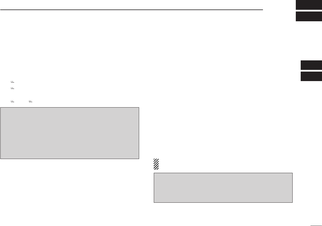
!0 TEST INDICATOR
Appears while the squelch test function is active (p. 20).
!1 LOCK INDICATOR (p. 19)
➥ Indicates “ ” while the dial lock function is in use.
➥ Indicates “ ” while the panel lock function in use.
CH09 SAMPLE
TEST
121.525
118.00
RX DUAL MEMORY RX
ICS
O
F
D
TX
etr y e
io!1
uq
!0
w

5
2
BASIC OPERATION
01
02
■ Frequency selection
IC-A210 has two ways to select a desired frequency.
ï General frequency selection
Select a desired frequency which is used for the next operat-
ing frequency in the standby frequency indicator. Then ex-
change the active frequency for the standby frequency.
NOTE: Operate from “Standby frequency selection(Step
1-2)” to “Frequency exchanging (Step 2-2)” as pages 5, 6.
ï Direct frequency selection
A desired frequency direct selection is available.
Refer to “Direct frequency selection mode operation.”
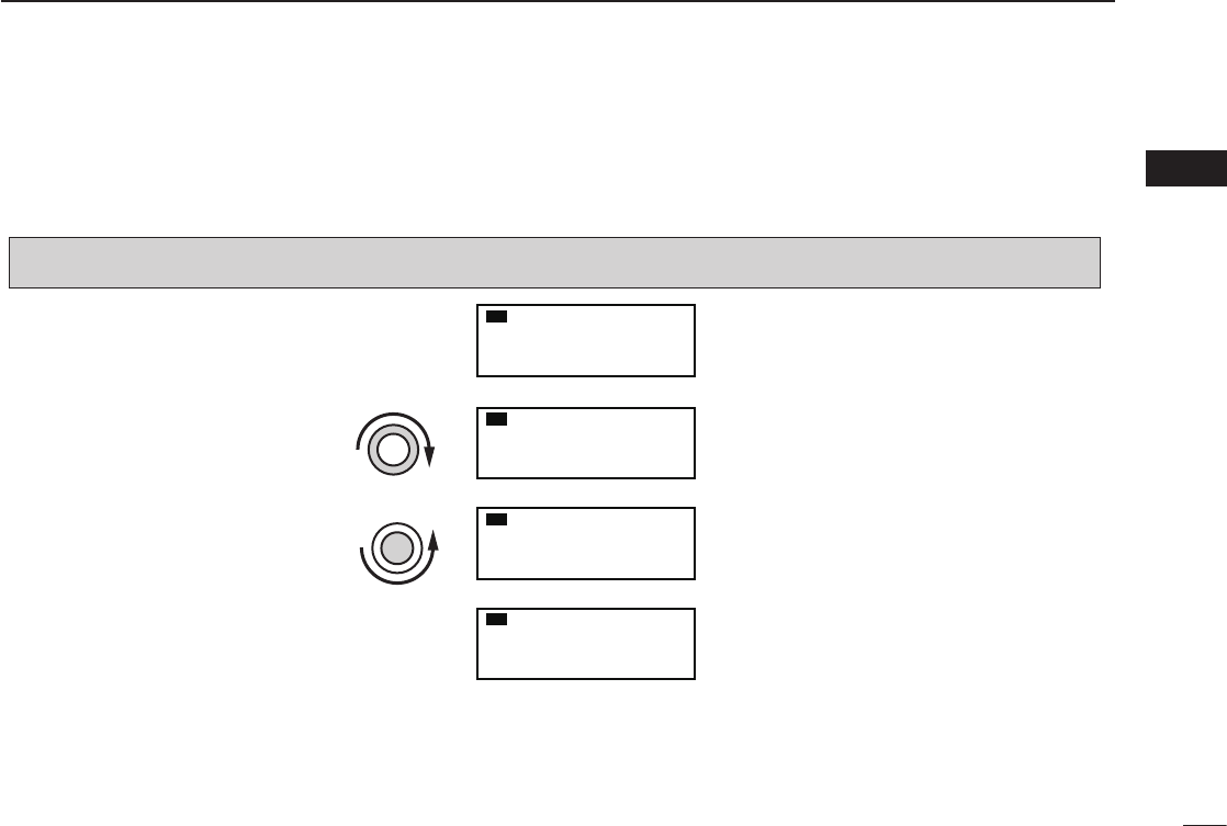
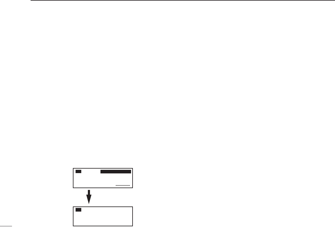
■ Standby frequency selection
(Step 1-2)
q Rotate [VOL] clockwise to turn power ON.
•Previouslyusedfrequenciesappearintheactiveand
standby frequency indicators.
w Rotate [DIAL] and [O-DIAL] to select a desired frequency
to the standby frequency.
•Theactivefrequencyisnotaffected.
•Rotate[O-DIAL] to set above 1 MHz digit.
•Rotate[DIAL] to set below 100 kHz digit.
TIP: For quick frequency setting, often used frequen-
cies can be programmed into memory channels. Refer to
“MEMORY OPERATION” (pages 9–18).
When a memory channel is recalled, the previous standby
frequency is erased.
CAUTION: DO NOT turn the power ON until the air-
craft engines have been started. It is very important for
protection of the power supply circuit.

6
2BASIC OPERATION
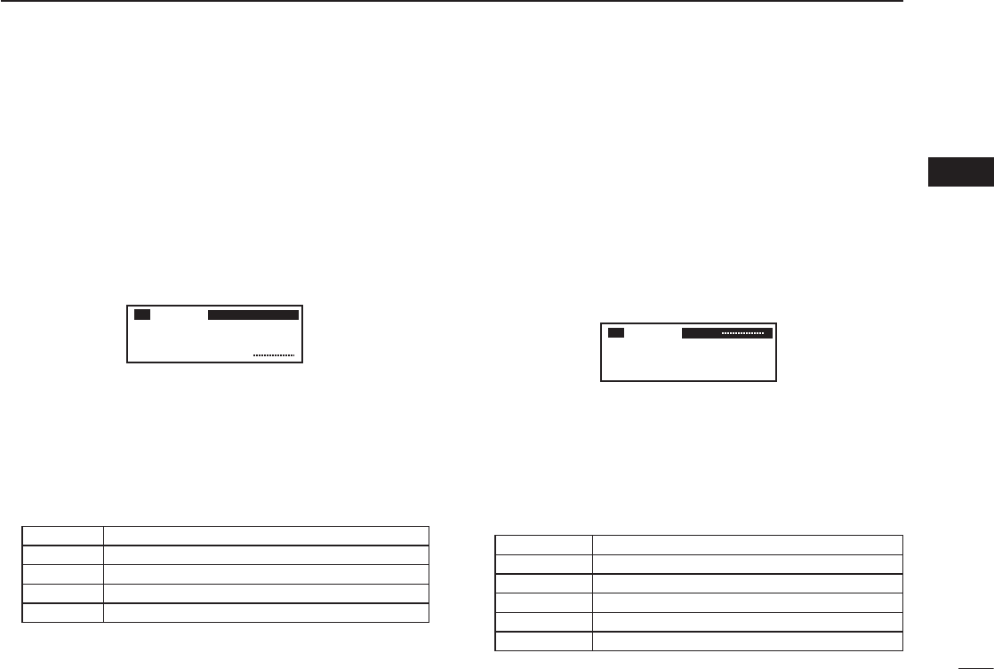
■ Frequency exchanging
(Step 2-2)
q After selecting the standby frequency, push [↔] to ex-
change it with the active frequency.
•Adjustthesquelchlevelinthemenumode,ifnecessary(p.23).
•Rotate[VOL] to set the volume level, if necessary.
•Whenreceivingasignal,“RX”appearsandaudioisheardfrom
the speaker or headset.
•Furtheradjustmentofaudiolevelmaybenecessaryatthis
point.
w Hold down [PTT] to transmit, then speak into the micro-
phone.
•Transmitindicator“TX”lights.
e Release [PTT] to receive.
Frequency exchanging can be also performed remotely from
the yoke-mounted frequency exchange switch.
■ Receiving
q Select an operating frequency.
•Refertopages5,6fordetails.
•“RX”appearswhenreceivingasignaloropeningsquelch.
w Push [VOL] to open the squelch manually.
•Refertopage20“Squelchtestfunction”fordetails.
e Rotate the volume control to adjust the audio level.
■ Transmitting
q Select the yoke-mounted communication/intercom switch
to the “communication” position.
w Select an operating frequency.
•Refertopages5,6indetails.
e Push the PTT switch.
•“TX”appears.
r Speak into the microphone at your normal voice level.
•DO NOT set the microphone too closely to your mouth or speak
too loudly. This may distort the signal.
t Release the PTT switch to receive.
NOTE: To prevent interference, listen on the frequency
before transmitting. If the frequency is busy, wait until the
frequency is clear.
NOTE: DO NOT hold down [↔] continuously. Other-
wise, the standby frequency disappears. If this happens,
again hold down [↔] until the standby frequency reap-
pears.
7
2
BASIC OPERATION
02
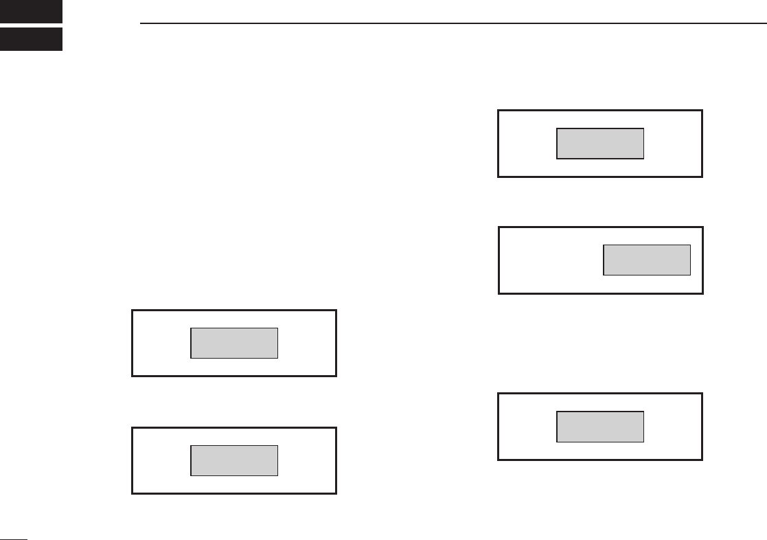
■ Frequency setting example
The following example shows to how to set 126.40 MHz as the standby frequency and then exchange it with the active fre-
quency indicator.
The active frequency and the standby
frequenies are exchanged.
Previously used frequencies appear.
Rotate the large tuning dial to change
the standby frequency in MHz steps.
Rotate the small tuning dial to change
the standby frequency in kHz steps.
121.805
134.80
RX
126.805
134.80
RX
126.405
134.80
RX
134.805
126.40
RX
qRotate [O-DIAL] clockwise to
select “126” MHz.
wRotate [DIAL] counterclockwise
to select “400” kHz.
ePush [�].
NOTE: DO NOT hold down [�]
continuously. Otherwise the sta-
ndby frequency disappears. If this
happens, hold down [�] until the
standy frequency reappears.
STEP DISPLAY NOTE
8
2BASIC OPERATION
■ Direct frequency setting
mode operation
The direct frequency setting mode operation is useful when
setting a desired frequency directly as the active frequency.
q Hold down [↔] for 2 seconds to enter the direct frequency
setting mode.
•Onlytheactivefrequencyisdisplayed.
w Set an operating frequency.
•Refertopages5,6indetails.
e Push [RCL] or [↔] to exit the direct frequency setting
mode.
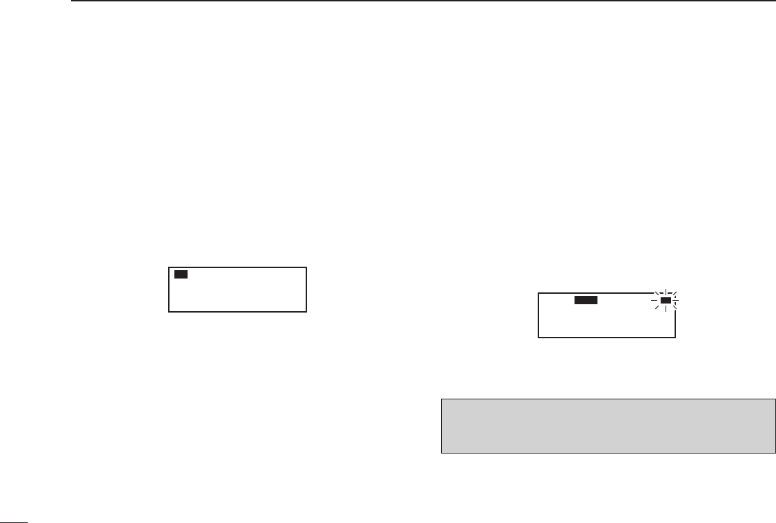
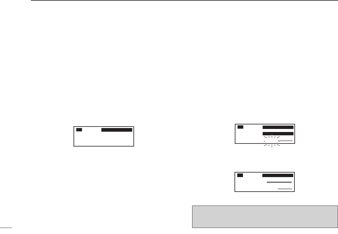
■ DualWatch operation
The DualWatch operation monitors the active frequency
at certain intervals even when receiving a signal on the
standby frequency. When a signal is received on the active
frequency, the radio switches to the active frequency and
stays on it until the signal disappears, irrespective of the
standby frequency status.
q Push [DUAL] to enter DualWatch operation.
•“DUAL”appearsontheactivefrequencyindicator.
•Theactiveorstandbyfrequency’s “RX” blinks when receiving a
signal or opening the squelch.
w Push [DUAL] again to exit DualWatch operation.
•“DUAL”disappears.
121.80
RX
129.405
121.00
RX DUAL RX
ATTENTION! During DualWatch operation, the standby
frequency’s audio may be interrupted at the monitoring in-
terval, but this is not a malfunction.

9
3
MEMORY OPERATION
02
03
■ Programming notes
ï Blank channel
A memory or group channel with no frequency content is
called as a blank channel. When a blank channel is selected
while memory programming, “–––––” appears instead of a
frequency.
ï Memory protect function
IC-A210 has a memory protect function. The function pre-
vents accidental changes or deletion.
The function can be set in the MENU mode (p. 24).
■ Entering memory mode
•Push[RCL] to enter the memory mode.
•Push[RCL] to set the selected memory channel frequency
to the standby frequency, then exit the memory mode.
•Holddown[RCL] for 2 seconds to exit the memory mode
without changing the previously set standby frequency.
■ Memory channel type
There are five memory types*. The memory types are as fol-
low:
* Depends on versions, there are 4 memory types.
ï Regular memory channel (MEMORY)
There are up to 10 available memory channels.
ï Group memory channel (GRP01–GRP20)
There are up to 200 group channels, with 10 channels in
each of 20 groups.
ï Weather memory channel (WEATHER)
(U.S.A. version ONLY)
10 weather memory channels are available.
They are used for monitoring NOAA (National Oceanic
and Atmospheric Administration) broadcasts (reception of
weather memory channels possible in U.S.A. version only).
ï History memory channel (HISTORY)
There are up to 10 available history memory channels.
The active frequency is written into history memory channels
automatically when pushing [↔] to exchange the active and
standby frequency (except weather channels: U.S.A. version
only).
ï GPS memory channel (GPS)
There are up to 10 available GPS memory channels.
When connected to an external GPS receiver* equipped with
an airport frequency database, the frequency data such as
nearby airports can be transferred into GPS memory chan-
nels.
* Ask your dealer for available GPS receiver details.

10
3MEMORY OPERATION
■ Programming a memory
channel
To program the memory channels, follow the steps below.
q Rotate [DIAL] and [O-DIAL] to set a desired frequency
for the standby frequency.
w Push [RCL] to enter the memory mode.
•Thechannelnumberappears.
•Thememorychannelnamealsoappearsifithasbeenentered.
e Rotate [O-DIAL] to select a desired memory channel
type.
•Selectregularmemorychannelorgroupmemorychannel.
r Push [MEM], and then rotate [O-DIAL] to select the “RE-
PLACE” menu.
•Thememorychannelnumberblinks.
t Rotate [DIAL] to select a memory channel to be pro-
grammed.
y Push [MEM], to program the frequency into the channel.
•“WRITECOMPLETED”appearsonthedisplaywhentheregu-
lar memory channel is programmed.
u Push [RCL] to exit the memory mode.
■ Channel selection
The transceiver has 10 channels in regular memory and 200
channels in the group memory. There are 10 channels in
each of 20 groups (GRP01–GRP20).
q Push [RCL] to enter the memory mode.
•Thechannelnumberappears.
•Thememorychannelnamealsoappearsifithasbeenentered.
w Rotate [O-DIAL] to select the memory channel type.
•Selectfromregularmemorychannelorgroupmemorychannel.
e Rotate [DIAL] to select a desired memory channel
number.
Transferring the memory channel to the active fre-
quency is necessary if you want to operate on the
memory channel frequency.
Refer to “Transferring memory contents” (p. 12) for
details.
r Push [RCL] to change to standby frequency to the se-
lected memory channel frequency and exit the memory
mode.
CH01
127.005
122.00
RX MEMORY
NOTE: Hold down [RCL] for 2 seconds to exit the mem-
ory mode without changing the previously set standby fre-
quency.
11
3
MEMORY OPERATION
03
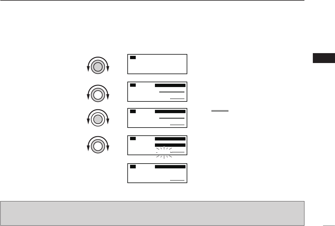
■ Programming example
The following is an example showing how to program 126.000 MHz into regular memory channel 4.
“ ” appears when no frequency
has been programmed into regular
memory channel 4.
“MEMORY” and the channel number
appear.
“126.00” appears in the standby
display.
126.005
134.80
RX
CH01
134.80
RX MEMORY
CH04
134.80
RX MEMORY
CH04
126.000
---.---
134.80
RX MEMORY
REPLACE Ç
CH04
126.005
134.80
RX MEMORY
Set a “126.000 MHz” in the
standby display.
q
Push [RCL], then rotate
[O-DIAL] to select “MEMORY”.
w
Push [MEM], then rotate
[O-DIAL] to select “REPLACE.”
r
Push [MEM] to store the
desired frequency into the
selected regular memory
channel.
t
Select regular memory channel
4 with [DIAL].
e
“WRITE COMPLETED” is displayed
when the selected frequency is
stored.
Regular memory channel number
blinks.
TIP: Hold down [MEM] for 2 seconds to program a displayed frequency into any blank memory channel automatically, after
step q.
NOTE: The programming is cancelled if all regular memory channels have already programmed.
12
3MEMORY OPERATION
■ Transferring memory
contents
This function transfers a memory channel’s contents into
the active frequency display and places the previous active
frequency into the standby display.
q Push [RCL] to enter the memory mode.
•Thechannelnumberappears.
•Thememorychannelnamealsoappearsifithasbeenentered.
w Rotate [O-DIAL] to select a desired channel type.
•Selectregular,grouphistory,weather*orGPSmemorychan-
nel.
* Selectable depending on versions.
e Rotate [DIAL] to select a memory channel to be trans-
ferred.
r Push [↔] to transfer the memory channel frequency into
the active frequency display.
•Thememorymodeisthencancelledautomatically.
■ Memory mode menu
( Regular and group memory
channels only)
ï REPLACE
Replacing the standby frequency with the memory channel
frequency.
ï DELETE
Deletes the selected memory channel.
ï REVIVE
Returns the selected memory channel to its previous state.
ï CH NAME (Regular memory channel only)
Sets the channel name to the selected regular memory
channel.
ï GRP NAME (Group memory channel only)
Sets the group name to the selected memory group.
ï CH TAG (Group memory channel only)
Sets the channel tag to the selected memory channel (Se-
lecting the group memory channel is the only option).
ï DONE
Return to the memory mode.
CH01
127.005
122.00
RX MEMORY
122.005
127.00
RX MEMORY
Push [↔].
13
3
MEMORY OPERATION
03
■ Regular memory channel
The transceiver has 10 regular memory channels.
Five programming options are selectable.
The following functions are available.
REPLACE, DELETE, REVIVE and CHANNEL NAME EDIT
functions.
q Push [RCL] to enter the memory mode.
•Thechannelnumberappears.
•Thememorychannelnamealsoappearsifithasbeenentered.
w Rotate [O-DIAL] to select the regular memory channel.
•“MEMORY”appears.
e Rotate [DIAL] to select a desired channel.
r Push [MEM], then rotate [O-DIAL] to select a menu op-
tion as follow.
•Thememorychannelnumberblinks.
t Push [MEM] to perform the selected action.
■
Group memory channel
The transceiver has 200 group memory channels comprised
of 10 channels in each of 20 groups.
The following functions are available.
REPLACE, DELETE, REVIVE GROUP NAME EDIT and
CHANNEL TAG functions.
q Push [RCL] to enter the memory mode.
•Thechannelnumberappears.
•Thememorychannelnamealsoappearsifithasbeenentered.
w Rotate [O-DIAL] to select the group memory channel number.
•Agroupnumber“GRP01–GRP20”appears.
e Push [DIAL], and then rotate [O-DIAL] to select the
memory group from GRP01 to GRP20 if necessary.
•Thegroupandchannelnumbersblink.
•Push[DIAL] again, or push [RCL] to set the memory group.
r Rotate [DIAL] to select a desired channel within the se-
lected group.
t Push [MEM], rotate [O-DIAL] to select a menu as follows.
•Thememorychannelnumberblinks.
y Push [MEM] to perform the selected action.
CH01
127.005
122.00
RX GRP01
CH01
127.005
122.00
RX MEMORY
REPLACE Replace to the standby frequency.
DELETE Delete the memory channel.
REVIVE Revive the previous memory channel data.
CH NAME Edit the memory channel name.
DONE Do nothing and return to the memory mode.
REPLACE Replace to the standby frequency.
DELETE Delete the memory channel.
REVIVE Revive the previous memory channel data.
GRP NAME Edit the group name.
CH TAG Set the memory channel as a tag channel.
DONE
Do nothing and return to the memory mode.
14
3MEMORY OPERATION
■
History memory channel
The transceiver has 10 history memory channels.
The standby frequency is stored into a history memory chan-
nel when pushing [↔].
The frequency is stored into the history memory channel in
order from “CH01” to “CH10.”
q Push [RCL] to enter the memory mode.
•Thechannelnumberappears.
•Thememorychannelnamealsoappearsifithasbeenentered.
w Rotate [O-DIAL] to select the history memory channel.
•“HISTORY”appears.
e Rotate [DIAL] to select a desired channel.
•Push[↔] to exchange the history memory channel frequency
to the active frequency if necessary.
r Push [RCL] to exit the memory mode.
■
Clearing the memory contents
( Regular and group memory
channels only)
Unwanted memory channels can be cleared.
q Push [RCL] to select memory mode.
•Thechannelnumberappears.
•Thememorychannelnamealsoappearsifithasbeenentered.
w Rotate [O-DIAL] to select the memory channel type.
•Selectfromregularmemorychannelorgroupmemorychannel.
e Rotate [DIAL] to select a desired channel.
r Push [MEM], then rotate [O-DIAL] to select “DELETE.”
•Thememorychannelnumberblinks.
t Push [MEM] to delete the memory channel data.
•“------------”appearsmomentarily,thenthenextselectable
channel appears.
y Push [RCL] to exit the memory mode.
CH01
127.005
122.00
RX HISTORY
CH01
127.000
127.000
122.00
RX MEMORY
ÅDELETE Ç
CH01
122.00
RX MEMORY
NOTE: Instead of steps r and t, holding down [MEM]
for 2 seconds after step e also allows delete or revive op-
eration.

15
3
MEMORY OPERATION
03
■
Programming channel names
(Regular memory channel only)
The regular memory channel can display a six character
name in addition to the memory number.
q Push [RCL] to enter the memory mode, then rotate [O-
DIAL] to select a desired regular memory channel in the
memory mode.
w Rotate [DIAL] to select a desired channel.
e Push [MEM], then rotate [O-DIAL] to select “CH NAME.”
r Push [MEM]. The memory channel name’s 1st digit blinks.
t Rotate [DIAL] to select a desired character.
•Thecharactertypeasshownbelowisselectable.
•Push[DIAL]toswitchfromcapitalletters(A,B,C,···)→ lower
case (a, b, c, ···) → number (0, 1, 2, ···) → then again to capital
letters (A, B, C, ···) in sequential order.
y Rotate [O-DIAL] to select the next input digit.
u Repeat t–y to input the memory channel name.
i Push [MEM] to set the memory channel name.
•Selectable characters
■ Programming group names
(Group memory channel only)
The memory groups can display a six character name in ad-
dition to the group number (“GRP01”–“GRP20”).
q Push [RCL], then rotate [O-DIAL] to select a desired
memory channel in the memory mode.
•Rotate[O-DIAL] to select the memory channel type if neces-
sary.
w Push [DIAL], and then rotate [O-DIAL] to select the
memory group from GRP01 to GRP20, if necessary.
•Push[DIAL] again to set the memory group.
e Push [MEM], then rotate [O-DIAL] to select “GRP
NAME.”
r Push [MEM], and the group name’s 1st digit blinks.
t Rotate [DIAL] to select a desired character.
•Thecharactertypeasshownleft“Selectablecharacters”are
selectable.
•Push[DIAL]toswitchfromcapitalletters(A,B,C,···)→ lower
case (a, b, c, ···) → number (0, 1, 2, ···) → then again to capital
letters (A, B, C, ···) in sequential order.
y Rotate [O-DIAL] to select the next input digit.
u Repeat t–y to input the group name.
i Push [MEM] to set the group name.
0 1 2 3 4 5 6 7 8 9 : ; < = > ? @
A B C D E F G H I J K L M N O P Q R S T U V W X Y Z [ \ ]
^ _ `
a b c d e f g h i j k l m n o p q r s t u v w x y z { | } ~ ■ ! ” #
$ % & ’ ( ) ∗ + , – . /
16
3MEMORY OPERATION
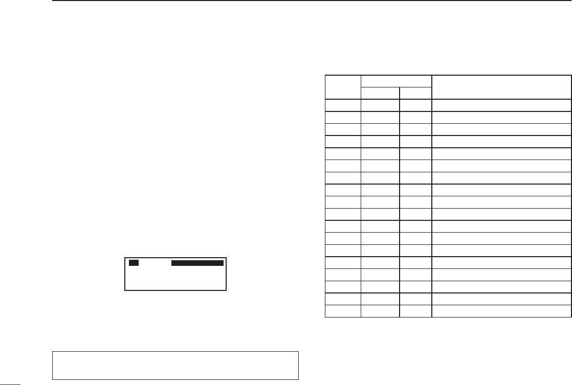
■ Programming channel tag
(Group memory channel only)
The tag name can be set a three character name in addition
to the group number. It is convenient for separating memory
type.
q Push [RCL], then rotate [O-DIAL] to select a desired
group memory channel in the memory mode.
•Rotate[O-DIAL] to select the memory channel type if neces-
sary.
w Push [MEM], then rotate [O-DIAL] to select “CH TAG”
when selecting “LABEL” in “Group memory channel dis-
play” of the menu mode (p. 24)
e Push [MEM], then rotate [DIAL] to select a desired chan-
nel tag.
•Thetagtypeasshownbelowisselectable.
r Push [MEM] to set the channel tag.
• Selectable tags
___ / TWR / GND / ATS / ATF / APP / ARR / AWS / CLR /
CTF / DEP / FSS / RFS / UNI / MF / OTH / U-1 / U-2
■
Channel tag list
*1Group memory, *2GPS memory
CH01
127.005
122.00
RX GRP01
TWR
TAG
NAME
DISPLAY MEANS
Group*1GPS*2
_ _ _ YES – Non-tag
TWR YES YES Tower
GND YES YES Ground
ATS YES YES ATIS
ATF YES YES Air traffic
APP YES YES Approach
ARR YES YES Arrival
AWS YES YES Automatic Weather Station
CLR YES YES Clearance / Delivery
CTF YES YES
Common Traffic Advisory Frequency
DEP YES YES Departure Frequency
FSS YES YES Flight Service Station
RFS YES YES Remote Flight Service Station
UNI YES YES Unicom frequency
MF YES YES Mandatory frequency
OTH YES – Other
U-1 YES – User1 setting (Refer to page 26)
U-2 YES – User2 setting (Refer to page 26)
17
3
MEMORY OPERATION
03
■ GPS memory
When connected to an external GPS receiver* equipped
with an airport frequency database, frequency data such as
nearby airports can be transferred and made available in the
GPS memory (maximum 10-memory channels).
*Ask your dealer for available GPS receiver details.
q Push [RCL] to enter the memory mode.
•Thechannelnumberappears.
w Rotate [O-DIAL] to select the GPS memory channel.
•“GPS”appears.
e Rotate [DIAL] to select a desired channel.
r Push [RCL] to exit the GPS memory mode.
■ Weather memory channel
(U.S.A. version only)
The U.S.A. version has VHF marine WX (weather) channel
receiving capability for flight planning.
q Push [RCL] to enter the memory mode.
•Thechannelnumberappears.
w Rotate [O-DIAL] to select the weather memory channel.
•“WEATHER”appears.
e Rotate [DIAL] to select a desired channel.
r Push [RCL] to exit the weather memory mode.
WX01
162.555
122.00
RX DUAL WEATHER
CH01 TWR
122.055
122.00
RX GPS RJTJ
Airport code
Tag name
• Weather memory channel list
NOTE:
•SeetheGPSreceiver’sinstructionmanualfortransferring
the frequency data.
•AskyourdealerforavailableGPSreceiverdetails.
Channel Frequency Channel Frequency
WX01 162.550 MHz WX06 162.500 MHz
WX02 162.400 MHz WX07 162.525 MHz
WX03 162.475 MHz WX08 161.650 MHz
WX04 162.425 MHz WX09 161.775 MHz
WX05 162.450 MHz WX10 163.275 MHz

18
3MEMORY OPERATION
■ GPS memory edit
The received GPS memory data is stored in the desired
group memory channel.
q Push [RCL] to enter the memory mode.
•Thechannelnumberappears.
•Thememorychannelnamealsoappearsifithasbeenentered.
w Rotate [O-DIAL] to select the GPS memory channel.
•“GPS”appears.
e Push [MEM] to enter the GPS memory channel edit
mode, then rotate [O-DIAL] to select a desired group
memory.
•“GPS”andairportcodeblink.
r Push [MEM] to store the GPS memory channel data to
the selected group memory.
t Push [RCL] to exit the memory mode.
NOTE:The GPS memory data is overwritten if the se-
lected GPS memory channel already contains other data.
■ Memory protection
The transceiver has memory protection which inhibits to
the editing (storing, deleting, replacing, etc.) of the memory
group memory channels.
Refer to “Memory Protection” (p. 24) for details.
19
4
OTHER FUNCTIONS
03
04
■ Lock function
The lock function prevents accidental frequency changes
and accidental function activation.
q Hold down [DIAL] for 2 seconds to turn the lock function
ON.
•“
O
D
” appears when DIAL lock mode is selected.
•“
O
P
” appears when PANEL lock mode is selected.
w To turn the function OFF, repeat step q above.
•“
O
D
” or “
O
P
” disappears.
■ Accessing 121.5 MHz
emergency frequency
The IC-A210 can be set to the 121.5 MHz emergency fre-
quency quickly. This function can be activated even when the
key lock function is in use.
q Push [EC] to call the emergency frequency to the standby
frequency, and enter the DualWatch operation automati-
cally.
w Push [↔] to transfer emergency frequency to the active
frequency if necessary.
•“EC”appears.
e Push [↔] to exit from the emergency frequency.
•Setthefrequencyexcept121.500MHzbeforepushing[↔] to
the standby frequency if necessary.
•“EC”disappears.
NOTE: “EC” also appears on the display while the active
frequency is set to 121.500 MHz.
NOTE: AUTOMATIC LOCK RELEASE FUNCTION
This transceiver has an “Automatic Lock Release Function”
which releases the Lock function automatically when an
operator gets into a panic.
The lock function is released when pushing any keys (ex-
cept [EC]) eight times or rotating any dials (except [VOL])
25-clicks for 5 seconds.
CONVENIENT!: Hold down [EC] for 2 seconds to enter
the direct frequency setting mode (p. 8), and set the emer-
gency frequency (121.5 MHz).
•“EC”appears.

20
4OTHER FUNCTIONS
■ Intercom function
When two headphone and microphone jacks are connected
to the transceiver, these headsets can be used as a voice-
activated intercom.
q Enter to the MENU mode.
•Seepage22fordetails.
w Set Intercom Usable Setting to ON.
•Seepage26fordetails.
e Exit from the MENU mode.
•Seepage22fordetails.
r Hold down [DUAL] for 2 seconds to enable the intercom
function.
•“ICS”appears.
•Theheadphoneaudiooutputlevelcanbeselected
“OFF,” “output level fixing (001–080)” or “interlocking
with [VOL]” in the MENU mode (p. 23).
•Themicrophone1andmicrophone2audioinputlevels
can be also selected “OFF” or “output level fixing (001–
080)” in the MENU mode (p. 23).
■ Squelch test function
This function opens the squelch manually for testing.
q Push [VOL] to turn the squelch test function ON.
•“TEST”appears.
w To turn the function OFF, repeat step q as above.
•“TEST”disappears.
■ Frequency step setting
Frequency step (8.33 kHz or 25 kHz) is selectable in the
menu mode.
q Enter the menu mode (See page 22 for details).
w Rotate [O-DIAL] to select the “FREQ. STEP (Frequency
step).”
e Rotate [DIAL] to select the desired frequency step
(8.33 kHz or 25 kHz).
r Push [RCL] to exit MENU mode, and returning to the pre-
vious operating condition.

21
4
OTHER FUNCTIONS
■ Weather memory channel
scan (U.S.A. version only)
Scanning searches for weather channel signals automati-
cally and makes it easier to listen purposes.
Repeatedly scans all weather memory channels.
This function is available for the U.S.A. version only.
q Set to the weather memory channel mode.
w Hold down [VOL] for 2 seconds to start weather memory
channel scan.
•Tochangethescandirection,turn[DIAL].
•“NOWTH”appearswhennosignalreceivesfromWX01–
WX10 channels. Then the weather memory channel scan stops
automatically.
•“SEARCH“asheswhilescanning.
e Hold down [VOL] for 2 seconds again to stop the scan.
162.555
122.00
RX WEATHER
SEARCH
04
22
5MENU MODE
■ MENU mode programming
MENU mode is available at power ON and allows you to set
seldom-changed settings. In this way you can customize
transceiver operations to suit your preferences and operating
style.
D Operating MENU mode
q Rotate [VOL] to turn the transceiver’s power ON.
w Push [RCL] to set VFO mode if memory mode is se-
lected.
e Hold down [RCL] for 2 seconds to enter the MENU mode.
r Rotate [O-DIAL] to select setting items.
t Rotate [DIAL] to select a desired setting.
y Push [RCL] to exit MENU mode, and returning to the pre-
vious operating mode.
• MENU mode items
MENU MODE
HP LEVEL AF GAIN
01/31
RCL
MEM
OFF
VOL
PUSH
TEST
COMM
DUAL
EC
iA210
AF GAIN
OFF
001
076
Desired condition setting
HP LEVEL
INCOM LV1
INCOM LV2
MIC1 SQL
Menu mode items setting
Menu mode items Items number
Setting value
p. 23
HP LEVEL
GRP MEMORY
INCOM LV2
INCOM LV1
MIC1 SQL
MIC2 SQL
ANL
SQL LEVEL
FM SQL LV*
*Not available on all versions.
LOCK MODE
DW INTERVAL
PRI. WATCH
MEM PROTECT
MIC2 GAIN
MIC1 GAIN
SIDETONE LV
DISP HIGH
DISP MAN.
AUX LEVEL
DISP MODE
DISP LOW
DISP RESP.
FREQ DISP
U-1 ID SET
U-2 ID SET
AUX IN
BEEP
INCOM MODE
TIME OUT
INTERLOCK
MEM CLEAR
p. 26
p. 27
p. 25
p. 25
p. 24
TX MIC SEL
FREQ. STEP

23
5
MENU MODE
■ MENU mode items
D AM Squelch Level “SQL LEVEL”
Set the squelch level for AM mode operation.
In order to receive signals properly, as well as for the scan
to function effectively, the squelch must be adjusted to the
proper level.
•–010–010:SettingAMsquelchlevelfrom–10to+10.
D FM Squelch Level “FM SQL LV”
(U.S.A. version only)
Set the squelch level for FM mode operation.
•–010–010:SettingFMsquelchlevelfrom–10to10.
D Headphone Level “HP LEVEL”
Set the headphone output level while receiving.
•AFgain :Theoutputlevelissameas[VOL].
•OFF(0) :Mutestheheadphone.
•001–080 :Setsaudiolevelfrom1to80.
D Intercom1 Microphone Audio Input Level
“INCOM LV1”
Set the intercom1 microphone input level.
•OFF(0) :Mutestheintercom1microphone.
•001–080 :Setstheintercom1inputlevelfrom1to80.
D Intercom2 Microphone Audio Input Level
“INCOM LV2”
Set the intercom2 microphone input level.
•OFF(0) :Mutestheintercom2microphone.
•001–080 :Setstheintercom2inputlevelfrom1to80.
D Intercom1 Squelch Level “MIC1 SQL”
Set the intercom1 squelch level.
The setting level is required to open the squelch when
speaking to the intercom1.
•OFF(0) :Turnsofftheintercom1squelch.
•001–030 :Setstheintercom1squelchlevelfrom1to30.
D Intercom2 Squelch Level “MIC2 SQL”
Set the intercom2 squelch level.
The setting level is required to open the squelch when
speaking to the intercom2.
•OFF(0) :Turnsofftheintercom2squelch.
•001–030 :Setstheintercom2squelchlevelfrom1to30.
05

24
5MENU MODE
■ MENU mode items (Continued)
D Automatic Noise Limiter “ANL”
The ANL (Automatic Noise Limiter) function reduces noise
components such as that caused by engine ignition systems
while receiving.
•OFF :ANLfunctionOFF.
•ON :ANLfunctionON.
D Lock Mode “LOCK MODE”
Set the lock function.
•OFF :ThelockfunctionisOFF.
•DIAL :Thelockfunctionappliesto[DIAL].
•PANEL :Thelockfunctionappliestobuttonsonthefrontpanel.
D DualWatch Interval “DW INTERVAL”
Set the interval time while operating DualWatch or weather
scan.
•FAST :Setstheintervaltimeto300milliseconds.
•MID :Setstheintervaltimeto600milliseconds.
•SLOW :Setstheintervaltimeto2seconds.
.
D Priority Watch Interval “PRI. WATCH”
Set the active frequency receive interval time while receiving
the standby frequency.
•FAST :Setstheintervaltimeto400milliseconds.
•MID :Setstheintervaltimeto800milliseconds.
•SLOW :Setstheintervaltimeto2seconds.
D Memory Protection “MEM PROTECT”
Set the memory protection to regular memory channels and
group memory channels.
Editing the regular memory and group memory channels is
inhibited while the protection is ON.
•OFF :ThememoryprotectionisOFF.
•ON :ThememoryprotectionisON.
D Group Memory Channel Display
“GRP MEMORY”
Set the displaying whether the label displays or not.
•CH :Onlythechannelnumberisdisplayed.
•LABEL :Thelabelisalsodisplayed.
D Microphone1 Gain “MIC1 GAIN”
Set the microphone1’s gain.
•–010–010:Settingthemicrophone1’sgainfrom–10to+10.
NOTE: The priority watch interval does not appear when
the “PRIORITY WATCH” is set to “OFF”, by the CS-A210.

25
5
MENU MODE
D Microphone2 Gain “MIC2 GAIN”
Set the microphone2’s gain.
•–010–010:Settingthemicrophone2’sgainfrom–10to+10.
D Sidetone Level “SIDETONE LV”
When using an optional headset (supplied from third party*)
via the adapter, the transceiver outputs your transmitted
voice to the headset for monitoring.
*Ask your dealer in details.
•OFF(0) :ThesidetonefunctionisOFF.
•001–080 :Setssidetonelevelfrom1to80.
D Transmitting Microphone Selection
“TX MIC SEL”
Set the active microphone when pushing microphone’s PTT
switch.
The item allows you to control which connected microphone
is permitted to transmit.
•MIC1 :Selectsmicrophone1.
•MIC2 :Selectsmicrophone2.
•MIC1+2 :Selectsbothmicrophone1andmicrophone2.
D Dimmer Mode “DISP MODE”
The light sensor which is built into the display is used for this
function.
Set the OLED dimmer mode.
•OFF :ThedimmerfunctionisOFF.
•AUTO :Setsthedimmerautomaticallydependingonlocal
brightness.
•MANUAL :SetsthedimmerdependingonDimmerBrightness
(Low) “DISP LOW.”
D Dimmer Brightness (Low) “DISP LOW”
Set the lower brightness level in the automatic adjustment
range when “AUTO” is selected at the “Dimmer Mode.”
The transceiver automatically adjusts its display brightness
by the current lighting conditions.
•OFF :ThekeybacklightsetsOFF.
•001–049 :Setslowdimmerbrightnesslevelfrom1to49.
D Dimmer Brightness (High) “DISP HIGH”
Set the upper brightness level in the automatic adjustment
range when “AUTO” is selected in the Dimmer Mode.
•050–100 :Setsdimmerbrightnesslevelfrom50to100.
05

26
5MENU MODE
■ MENU mode items (Continued)
D Dimmer Brightness (Manually) “DISP MAN.”
Set the brightness manually to suit your own preferences.
•000–100 :Settingdimmerlevelmanuallyfrom0(OFF)to100.
D Dimmer Response “DISP RESP.”
Set the dimmer switching speed when selecting “AUTO” at
the “Dimmer Mode.”
•STANDARD :Selectsnormalswitchingspeed.
•FAST :Selectsfastswitchingspeed.
D Frequency Display “FREQ DISP”
Set the 1 kHz digit frequency displaying in the OLED.
•OFF :The1kHzdigitisnotdisplayedintheOLED.
•ON :The1kHzdigitisalwaysdisplayedintheOLED.
•ZEROSUPP. :The1kHzisdigitdisplayontheOLEDas0.
D USER-1 Setting “U-1 ID SET”
Set the USER-1, channel tag, to a desired ID.
q Push [MEM] to enter the U-1 ID edit mode.
w Rotate [DIAL] to select a desired character.
e Rotate [O-DIAL] to select the next input digit.
r Repeat w–e to input the U-1 ID.
t Push [MEM] again to store the U-1 ID, and exit the edit mode.
D USER-2 Setting “U-2 ID SET”
Set the USER-2, channel tag, to a desired ID.
q Push [MEM] to enter the U-2 ID edit mode.
w Rotate [DIAL] to select a desired character.
e Rotate [O-DIAL] to select the next input digit.
r Repeat w–e to input the U-2 ID.
t Push [MEM] again to store the U-2 ID, and exit the edit mode.
D External Input “AUX IN”
Set the external input mode.
•OFF :TheexternalinputisOFF.
•ON :Theexternalinputisavailablewhilethesquelchis
closed.
•INCOM :Theexternalinputisavailablewiththeintercomopera-
tions as following.
- The intercom function is OFF.
- While the intercom function is not in use.
- While an audio signal is not input into the intercom’s
microphone.
D External Input Level “AUX LEVEL”
Set the external input level.
•OFF(0) :Theexternalinputdoesnotoperate.
•001–080 :Setstheexternalinputlevelfrom1to80.
•AFGAIN :Interlockedwith[VOL].

27
5
MENU MODE
D Beep Tone Level “BEEP”
Confirmation beep tones normally sound when storing mem-
ory, operating time-out-timer function, etc. These can be set
a desired beep level as you prefer.
•OFF(0) :ThebeeptoneturnsOFF.
•001–100 :Settingthebeeptonelevelfrom1to100.
D Intercom Usable Setting “INCOM MODE”
Set the intercom using or not.
•ON :Theintercomisusable.
•OFF :Theintercomisunusable.
D Time-Out-Timer “TIME OUT”
To prevent accidental prolonged transmission, the trans-
ceiver has a time-out-timer function. This timer starts when a
transmission begins, and will cut off the transmission when
the time set in the timer elapses.
•020–240 :Settingtime-out-timerstartingperiodfrom20seconds
to 240 seconds in 10 secons intervals.
D Frequency Step “FREQ. STEP”
Set the desired frequency step: 8.33 kHz or 25 kHz.
•25kHz :Settingthefrequencystepto25kHz.
•8.33kHz :Settingthefrequencystepto8.33kHz.
D Interlock “INTERLOCK”
When two transceivers are connected together, the interlock
function can prevent them from transmitting at the same
time.
•TXINHIBIT :Transmissionisprevented.
•RXMUTE :Audiooutputisprevented.
•BOTH :Transmissionandaudiooutputarebothprevented.
D Memory Clear “MEM CLEAR”
Set values in the CPU are cleared.
Hold down [MEM] for 2 seconds, the CPU is reset as follows.
•MENU :MENUmodeitemsarereset.
•MEMORY :Storedmemoriesarereset.
•ALL :AllCPUdataisreset.
05
NOTE: When using an external speaker, the beep tone
level when the squelch is closed is fixed and cannot be
changed in the MENU mode. NOTE: The interlock does not appear when the “TX/RX
INTERLOCK SW” is set to “DISABLE,” by the CS-A210.
28
6CLONING
D Data cloning
Cloning allows you to quickly and easily transfer the
programmed contents or data from a PC to a transceiver
using the optional CS-A210 CLONING SOFTWARE.
Data can be cloned to and from a PC (IBM compatible)
using the optional CS-A210 CLONING SOFTWARE and the op-
tional OPC-1529R CLONING CABLE (connect with the data jack).
Consult the CS-A210 instruction manual and HELP file for
details.
D Displayed Message
•Whileclonewriting.
•Whenclonewritingisnishedproperly.
•Whenclonewritingerroroccurs.
•Whileclonereading.
•Ifanerroroccurswhilecloning,thefollowingmessageap-
pears when the power is turned OFF and then ON. In this
case, re-cloning or re-writing the data correctly is neces-
sary to cancel the error.
CLONE
WRITE
CLONE
WRITE OK
CLONE
WRITE ERR
CLONE
READ
CLONE
READ
127.00
RX MEMORY
CLONE
NO DATA
29
7
OPTIONS
06
07
D CS-A210
c l o n i n g s o f t w a r e
Provides quick and easy programming of items, including
private channels, scan settings, etc., via a Windows® PC to
the transceiver (Microsoft® Windows® 2000/Me/XP/Windows
Vista®).
D OPC-1529R
c l o n i n g c a b l e
This cloning cable provides convenient connection to a PC
to access programmable features, such as memory chan-
nels, memory name, etc.
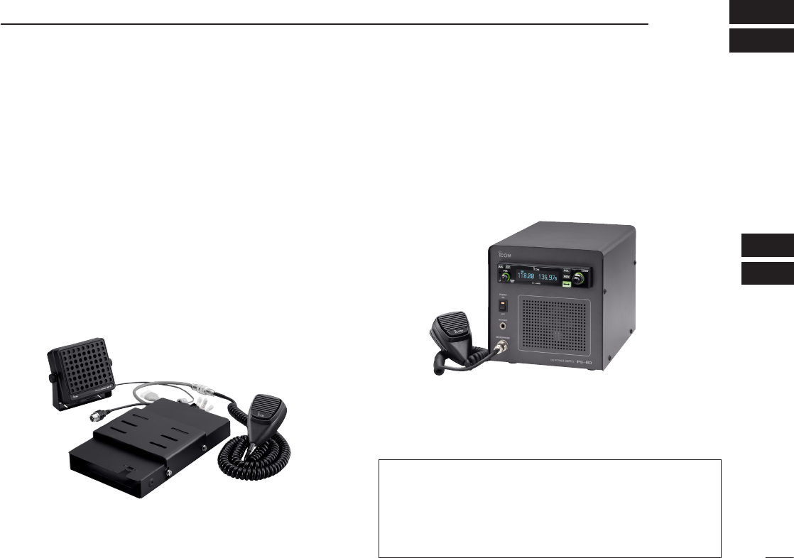
D MB-53
m o u n t i n g b r a c k e t
For mounting the transceiver to a vehicle. The external
speaker and microphone are included.
D PS-80
p o w e r s u p p ly
Provides convenient operation of the transceiver on the
ground. A built-in speaker and microphone* are included.
*Depending on version.
NOTE: PS-80’s specifications
Dimensions : 200 (W) × 200 (H) × 300 (D) mm
7.9 (W) × 7.9 (H) × 11.8 (D) in
Outputs : 13.8 V DC / 6 A
D MB-113
r e a r pa n e l a d a p t e r
For the third party compatible type with rear panel adapter.
Ask your dealer for compatible panel mount radio details.
NOTE: Supplied with some transceiver’s versions.
Approved Icom optional equipment is designed for optimal
performance when used with an Icom transceiver.
Icom is not responsible for the destruction or damage to an
Icom transceiver in the event the Icom transceiver is used
with equipment that is not manufactured or approved by
Icom.

30
8SPECIFICATIONS
D General
• Frequency range : 118.000 to 136.975 MHz
161.650 to 163.275 MHz*1
• Channel spacing : 25/8.33*2 kHz
• Frequency stability : ±5 ppm
• Operating temperature : –20˚C to +55˚C
–4˚F to +131˚F
• Antenna impedance : 50 ø
• Number of memory channels : 10 memory channels
200 group channels
10 history channels
10 GPS channels
10 weather channels*1
• Mode : AM (6K00A3E/5K6A3E*2)
• Power supply requirement : 13.80 V / 27.50 V DC
(negative ground)
• Dimensions : 160 (W)✕34 (H)✕271 (D) mm
(projections not incl.)
65/16(W)✕111/32(H)✕1021/32(D)
in
• Weight (approximately) : 1.0 kg; 2.2 lb
*1U.S.A. version only, receiving only.
*2U.S.A. version only
D Transmitter
• Mode : AM
• Output power : 8 W (Carrier power)
• Spurious emissions : –60 dBc
• Microphone impedance : 600 ø
• Modulation limiting : 70% (Max 98%)
D Receiver
• Receive system : Double conversion
superheterodyne
• Intermediate frequencies : 1st 38.85 MHz
2nd 450 kHz
• Sensitivity : (AM) Less than 2 µV (pd)
at 6 dB S/N
(FM) Less than 1.4 µV
at 12 dB SINAD*1
• Selectivity : 6 dB ±3 kHz
60 dB ±22 kHz
• Spurious response rejc. : More than 74 dBµ
• Audio output power : 5 W with a 4 ø load (External
speaker)
60 mW with a 500 ø load
(Headphone)
Measurements made in accordance with RTCA DO-186B for
U.S.A. version. All stated specifications are subject to change
without notice or obligation.

31
8
SPECIFICATIONS (VFO CHANNEL ID LIST)
01
02
03
04
05
06
07
08
09
10
11
12
13
14
15
16
• Channel spacing: 25 kHz (Actual frequency is displayed.)
Operating Frequency
(MHz)
Channel spacing
(kHz)
Channel ID
(Displayed Frequency)
118.0000 25 118.000
118.0250 25 118.025
118.0500 25 118.050
118.0750 25 118.075
118.1000 25 118.100
• Channel spacing: 8.33 kHz
Operating Frequency
(MHz)
Channel spacing
(kHz)
Channel ID
(Displayed Frequency)
118.0000 8.33 118.005
118.0083 8.33 118.010
118.0167 8.33 118.015
118.0250 8.33 118.030
118.0333 8.33 118.035
118.0417 8.33 118.040
118.0500 8.33 118.055
118.0583 8.33 118.060
118.0667 8.33 118.065
118.0750 8.33 118.080
118.0833 8.33 118.085
118.0917 8.33 118.090
118.1000 8.33 118.105
These tables show just the display example between 118.0000 MHz
and 118.1000 MHz, not show all frequencies in the band.

32
9SAFETY TRAINING INFORMATION
Your Icom radio generates RF electromag-
netic energy during transmit mode. This
radio is designed for and classified as “Oc-
cupational Use Only”, meaning it must be
used only during the course of employment
by individuals aware of the hazards, and
the ways to minimize such hazards. This
radio is NOT intended for use by the “Gen-
eral Population” in an uncontrolled environ-
ment.
•ForcompliancewithFCCandIndustryCanadaRFExpo-
sure Requirements, the transmitter antenna installation
shall comply with the following two conditions:
1. The transmitter antenna gain shall not exceed 0 dBi.
2. The antenna is required to be located outside of a ve-
hicle and kept at a distance of 36 centimeters or more
between the transmitting antenna of this device and
any persons during operation. For a small vehicle, the
antenna as worst case, the antenna shall be located on
the roof top at any place on the centre line along the
vehicle in order to achieve 36 centimeters separation
distance. In order to ensure this distance is met, the
installation of the antenna must be mounted at least 36
centimeters away from the nearest edge of the vehicle
in order to protect against exposure to bystanders.
To ensure that your exposure to RF elec-
tromagnetic energy is within the FCC
allowable limits for occupational use, al-
ways adhere to the following guidelines:
•DO NOT operate the radio without a proper antenna at-
tached, as this may damage the radio and may also cause
you to exceed FCC RF exposure limits. A proper antenna
is the antenna supplied with this radio by the manufacturer
or an antenna specifically authorized by the manufacturer
for use with this radio.
•DO NOT transmit for more than 50% of total radio use time
(“50% duty cycle”). Transmitting more than 50% of the time
can cause FCC RF exposure compliance requirements to
be exceeded. The radio is transmitting when the “TX indica-
tor” appears. You can cause the radio to transmit by press-
ing the “PTT” switch.
Electromagnetic Interference/Compatibility
During transmissions, your Icom radio generates RF energy
that can possibly cause interference with other devices or
systems. To avoid such interference, turn off the radio in
areas where signs are posted to do so. DO NOT operate the
transmitter in areas that are sensitive to electromagnetic ra-
diation such as hospitals, aircraft, and blasting sites.
33
9
INFORMATION EN MATIÈRE DE SÉCURITÉ
01
02
03
04
05
06
07
08
09
10
11
12
13
14
15
16
Votre radio Icom produit une énergie élec-
tromagnétique de radiofréquences (RF),
en mode de transmission. Cette radio est
conçue pour un «usage professionnel seu-
lement» et classée comme tel, ce qui si-
gnifie qu'elle doit être utilisée uniquement
dans le cadre d'un travail par des person-
nes conscientes des dangers et des me-
sures visant à minimiser ces dangers. Elle
N'EST PAS conçue pour une «utilisation
grand public», dans un environnement non
contrôlé.
•AndesatisfaireauxexigencesdelaFCCetd'Industrie
Canadaenmatièred'expositionauxRF,ilestnécessaire
quel'antennesoitinstalléeconformémentauxdeuxcondi-
tions suivantes:
1.Legaindel'antenneduradioémetteurnedoitpasdé-
passer 0 dBi.
2.Ilfautquel'antenneémettricedecetappareilsoitplacée
àl'extérieurd'unvéhiculeettenueéloignéed'aumoins
36 centimètres de toute personne pendant le fonction-
nement. Dans le pire des cas, pour un petit véhicule,
l'antennedoitêtreplacéesurletoit,n'importeoùdans
l'axecentralduvéhicule,anderespecterunedistance
de 36 cm du bord le plus rapproché du véhicule et ainsi
éviter que les personnes présentes soient exposées.
Afin de vous assurer que votre exposition à
une énergie électromagnétique de RF se situe
dans les limites permises par la FCC pour
une utilisation grand public, veuillez en tout
temps respecter les directives suivantes:
•
NE PASfairefonctionnerlaradiosansqu'uneantenneap-
propriéeysoitxée,carcecirisqued'endommagerlaradio
et causer une exposition supérieure aux limites établies par
laFCC.L'antenneappropriéeestcellequiestfournieavec
cette radio par le fabricant ou une antenne spécialement
autoriséeparlefabricantpourêtreutiliséeaveccetteradio.
•NE PASémettrependantplusde50%dutempstotald'utili-
sationdel'appareil(«50%dufacteurd'utilisation»).Émettre
pendantplusde50%dutempstotald'utilisationpeutcau-
ser une exposition aux RF supérieure aux limites établies
par la FCC. La radio est en train d’émettre lorsque le témoin
dumodedetransmissions'afchesurl'écranACL.Laradio
émettra si vous appuyez sur le bouton du microphone.
Interférence électromagnétique et compatibilité
Enmodedetransmission,votreradioIcomproduitdel'éner-
giedeRFquipeutprovoquerdesinterférencesavecd'autres
appareils ou systèmes. Pour éviter de telles interférences,
mettezlaradiohorstensiondanslessecteursoùunesigna-
lisation l’exige. NE PASfairefonctionnerl'émetteurdansdes
secteurs sensibles au rayonnement électromagnétique tels
que les hôpitaux, les aéronefs et les sites de dynamitage.
AVERTISSEMENT
MISE EN GARDE

34
10 FOR CLASS B UNINTENTIONAL RADIATORS
This equipment has been tested and found to comply with
the limits for a Class B digital device, pursuant to part 15 of
the FCC Rules. These limits are designed to provide reason-
able protection against harmful interference in a residential
installation. This equipment generates, uses and can radiate
radio frequency energy and, if not installed and used in ac-
cordance with the Instructions, may cause harmful interfer-
ence to radio communications. However, there is no guaran-
tee that interference will not occur in a particular installation.
If this equipment does cause harmful interference to radio or
television reception, which can be determined by turning the
equipment off and on, the user is encouraged to try to cor-
rect the interference by one or more of the following meas-
ures:
•Reorientorrelocatethereceivingantenna.
•Increasetheseparationbetweentheequipmentandre-
ceiver.
•Connecttheequipmentintoanoutletonacircuitdiffer-
ent from that to which the receiver is connected.
•Consultthedealeroranexperiencedradio/TVtechni-
cian for help.

35
INDEX
A
Accessing 121.5 MHz emergency frequency · 19
AM squelch level ·············································23
Automatic noise limiter ···································24
B
Basic operation ·················································5
Beep tone level ···············································27
Blank channel ···················································9
C
Channel selection ···········································10
Channel tag list ···············································16
Clearing the memory contents ·······················14
Cloning ···························································28
D
Data cloning ···················································28
Dimmer brightness (High)·······························25
Dimmer brightness (Low) ·······························25
Dimmer brightness (Manually) ························26
Dimmer mode ················································25
Dimmer response ···········································26
Direct frequency selection ································5
Direct frequency setting mode operation ··········8
Displayed message ········································28
DualWatch interval ·········································24
DualWatch operation ········································8
E
Emergency frequency ·····································19
Entering memory mode ····································9
External input ·················································26
External input level ·········································26
F
FM squelch level ·············································23
Frequency display ···········································26
Frequency exchanging ·····································6
Frequency selection··········································5
Frequency setting example ·······························7
Frequency step setting ···································20
Front panel························································1
Function display ················································4
G
General frequency selection ·····························5
GPS memory ··················································17
GPS memory channel ······································9
GPS memory edit ···········································18
Group memory channel ······························9, 13
Group memory channel display ······················24
H
Headphone level ·············································23
History memory channel ·····························9, 14
I
Intercom function ············································20
Intercom usable setting ··································27
Intercom1 Microphone audio input level ·········23
Intercom1 squelch level ··································23
Intercom2 Microphone audio input level ·········23
Intercom2 squelch level ··································23
Interlock ··························································27
L
Lock function ··················································19
Lock mode ······················································24
M
Memory channel type ·······································9
Memory clear ··················································27
Memory mode menu ······································12
Memory operation ············································9
Memory protect function ···································9
Memory protection ····································18, 24
Menu mode items ···········································23
Menu mode programming ······························22
Microphone1 gain ··········································24
Microphone2 gain ··········································25
O
Operating menu mode ····································22
Other functions ···············································19
P
Panel descriptions ············································1
Priority watch interval ·····································24
Programming channel names ·························15
Programming channel tag ······························16
Programming example ····································11
Programming group names ····························15
Programming notes ··········································9
Programming a memory channel ···················10
R
Regular memory channel ···························9, 13
S
Safety training information ······························32
Sidetone level ···············································25
Squelch test function ······································20
Standby frequency selection ····························5
T
Time-Out-Timer ··············································27
Transferring memory contents ························12
Transmitting ······················································6
Transmitting microphone selection ················25
U
USER-1 setting ···············································26
USER-2 setting ···············································26
W
Weather memory channel ··························9, 17
Weather memory channel scan ······················21
01
02
03
04
05
06
07
08
09
10
11
12
13
14
15
16

A-6602H-1EX-y
Printed in Japan
© 2007–2011 Icom Inc.
Printed on recycled paper with soy ink. 1-1-32 Kamiminami, Hirano-ku, Osaka 547-0003, Japan