ICOM orporated 297400 VHF Air Band Transceiver User Manual IC A210 INSTRUCTION MANUAL Draft version
ICOM Incorporated VHF Air Band Transceiver IC A210 INSTRUCTION MANUAL Draft version
UserManual.wiki
>
ICOM orporated
>
297400 User Manual
>
User Manual
Contents
1.
Manual Revised
2.
User Manual
User Manual
Navigation menu
Upload a User Manual
Namespaces
Wiki Guide
HTML
PDF
Info
Views
User Manual
Discussion / Help
Navigation
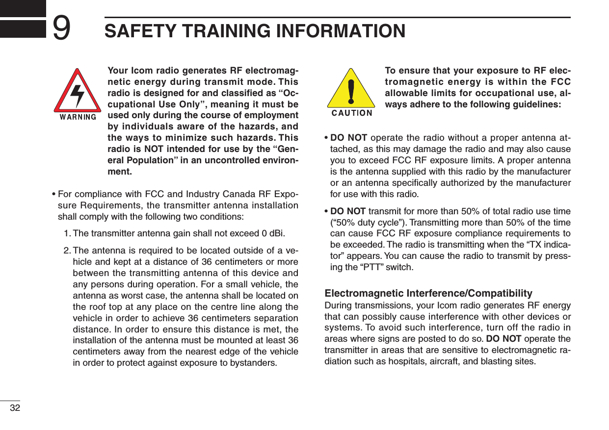
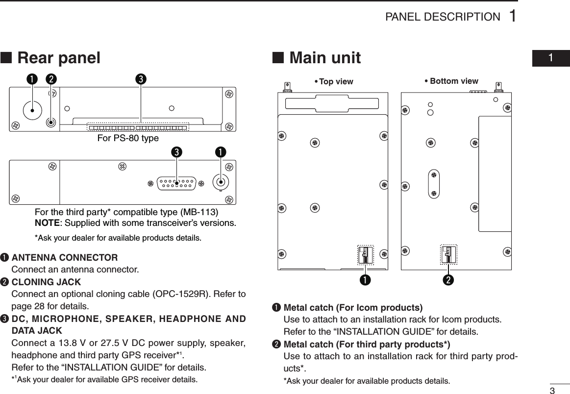
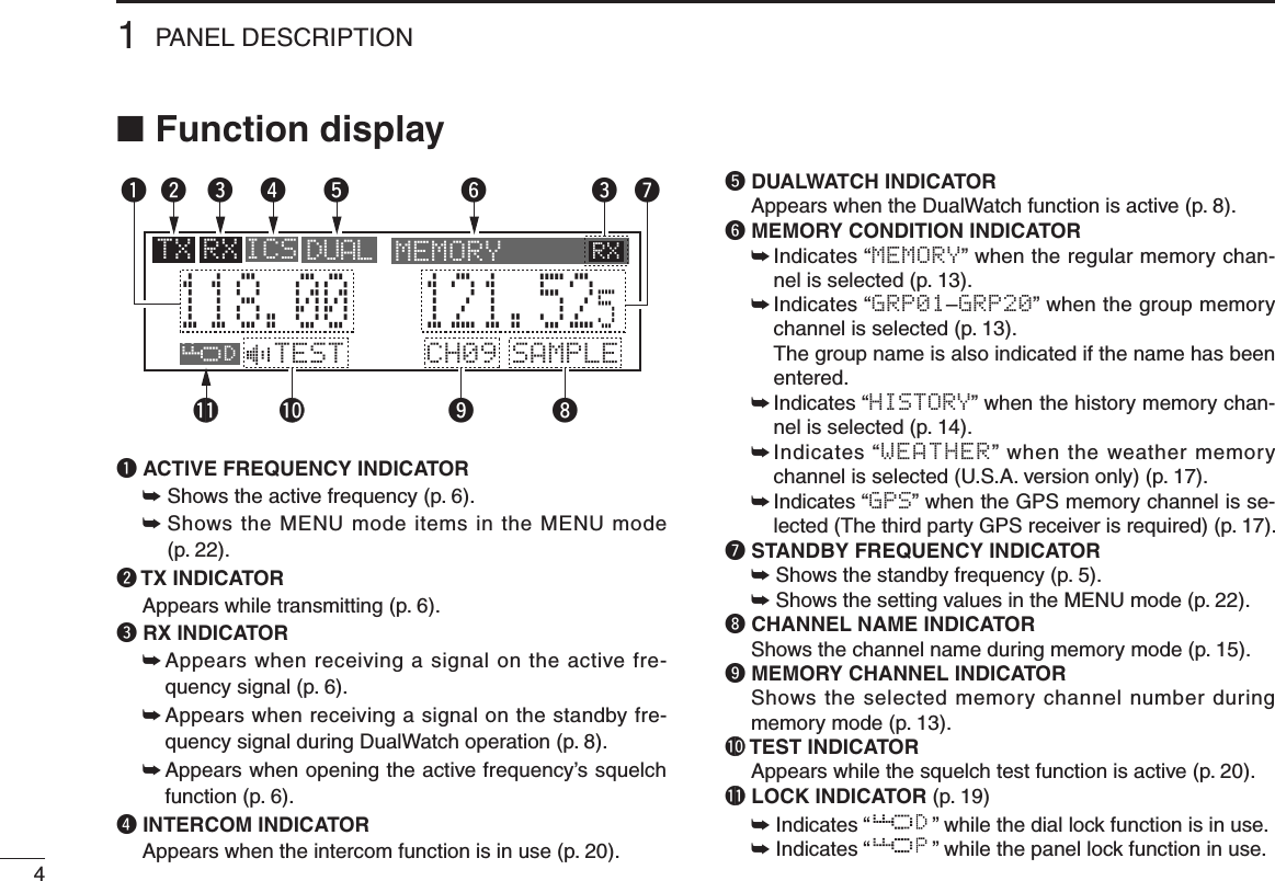
![11PANEL DESCRIPTION 01■ Front panelq DUAL SWITCH [DUAL]➥ Push to turn DualWatch operation ON or OFF (p. 8).➥ Hold down for 2 seconds to turn the intercom function ON or OFF.w EMERGENCY CHANNEL SWITCH [EC]➥ Push to set the emergency frequency (121.5 MHz) as the standby frequency (p. 19).➥ Hold down for 2 seconds to enter the direct frequency setting mode (p. 8), and set the emergency frequency (121.5 MHz) (p. 19).e VOLUME/POWER SWITCH [VOL]➥ Turn [VOL] to switch the power ON or OFF (p. 5).➥ Adjusts the audio output level. The volume level bar appears while rotating [VOL].➥ Push to set the squelch test function ON or OFF (p. 20).➥ Hold down for 2 seconds to start the weather channel (U.S.A. version only) scan (p. 21).r FREQUENCY EXCHANGE (FLIP-FLOP) SWITCH [↔]➥ Push to exchange the standby frequency with the ac-tive frequency (p. 6).➥ Hold down for 2 seconds to enter direct frequency set-ting mode (p. 8).RCLMEMOFFVOLPUSHTESTCOMMDUALECiA210CH09 SAMPLE121.525118.00RX MEMORYeytriouqw](https://usermanual.wiki/ICOM-orporated/297400.User-Manual/User-Guide-1507287-Page-5.png)
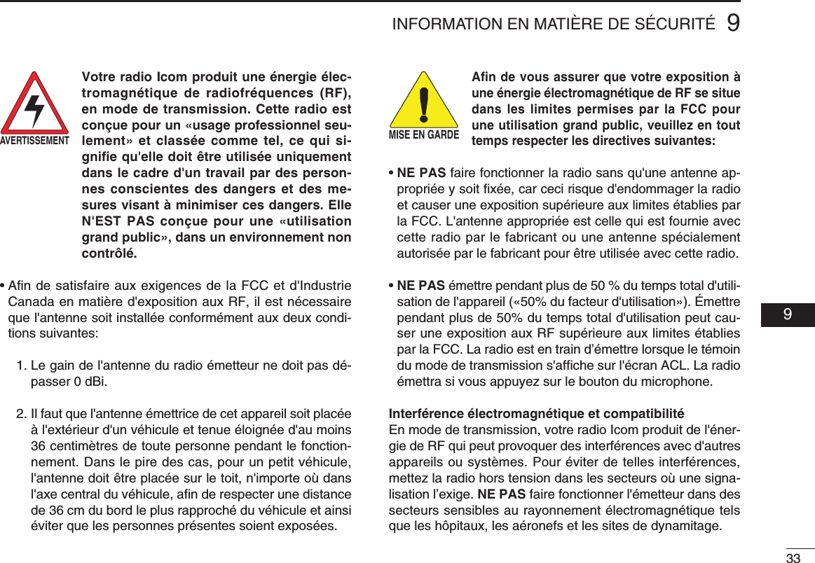
![21PANEL DESCRIPTION■ Front panel (Continued)t MEMORY SWITCH [MEM] Hold down for 2 seconds to program a displayed fre-quency to any blank regular memory channel or delete/revive the selected memory channel (depending on the operating mode) (p. 9).y RECALL SWITCH [RCL]➥ Push to enter/exit the memory mode (p. 9).➥ Hold down for 2 seconds to enter the menu mode (p. 22).u LIGHT-SENSITIVE DETECTOR This detector senses ambient light. The detector is used to adjust “Dimmer brightness (Low/High)” (p. 25) auto-matically when the “Dimmer Mode” (p. 25) is set to ‘AUTO.’i INNER (Small) TUNING DIAL [DIAL]➥ Rotate to set the standby frequencies (kHz digit) (p. 5), memory channels (p. 10), MENU mode settings (p. 22).➥ Hold down for 2 seconds to turn the dial/panel lock function ON (p. 19).o OUTER (Large) TUNING DIAL [O-DIAL]➥ Rotate to set the standby frequency (MHz digit) (p. 5), group memory channel (p. 13), cursor position (p. 15), etc.➥ Rotate to change the scan direction while scanning (p. 21).RCLMEMOFFVOLPUSHTESTCOMMDUALECiA210CH09 SAMPLE121.525118.00RX MEMORYeytriouqw](https://usermanual.wiki/ICOM-orporated/297400.User-Manual/User-Guide-1507287-Page-6.png)
![52BASIC OPERATION 01 02■ Frequency selectionIC-A210 has two ways to select a desired frequency.ï General frequency selectionSelect a desired frequency which is used for the next operat-ing frequency in the standby frequency indicator. Then ex-change the active frequency for the standby frequency.NOTE: Operate from “Standby frequency selection(Step 1-2)” to “Frequency exchanging (Step 2-2)” as pages 5, 6.ï Direct frequency selectionA desired frequency direct selection is available.Refer to “Direct frequency selection mode operation.”■ Standby frequency selection (Step 1-2)q Rotate [VOL] clockwise to turn power ON. •Previouslyusedfrequenciesappearintheactiveandstandby frequency indicators.w Rotate [DIAL] and [O-DIAL] to select a desired frequency to the standby frequency. •Theactivefrequencyisnotaffected. •Rotate[O-DIAL] to set above 1 MHz digit. •Rotate[DIAL] to set below 100 kHz digit.TIP: For quick frequency setting, often used frequen-cies can be programmed into memory channels. Refer to “MEMORY OPERATION” (pages 9–18).When a memory channel is recalled, the previous standby frequency is erased.CAUTION: DO NOT turn the power ON until the air-craft engines have been started. It is very important for protection of the power supply circuit.](https://usermanual.wiki/ICOM-orporated/297400.User-Manual/User-Guide-1507287-Page-9.png)
![62BASIC OPERATION■ Frequency exchanging (Step 2-2) q After selecting the standby frequency, push [↔] to ex-change it with the active frequency. •Adjustthesquelchlevelinthemenumode,ifnecessary(p.23). •Rotate[VOL] to set the volume level, if necessary. •Whenreceivingasignal,“RX”appearsandaudioisheardfromthe speaker or headset. •Furtheradjustmentofaudiolevelmaybenecessaryatthispoint.w Hold down [PTT] to transmit, then speak into the micro-phone. •Transmitindicator“TX”lights.e Release [PTT] to receive.Frequency exchanging can be also performed remotely from the yoke-mounted frequency exchange switch.■ Receivingq Select an operating frequency. •Refertopages5,6fordetails. •“RX”appearswhenreceivingasignaloropeningsquelch.w Push [VOL] to open the squelch manually. •Refertopage20“Squelchtestfunction”fordetails.e Rotate the volume control to adjust the audio level.■ Transmittingq Select the yoke-mounted communication/intercom switch to the “communication” position.w Select an operating frequency. •Refertopages5,6indetails.e Push the PTT switch. •“TX”appears.r Speak into the microphone at your normal voice level. •DO NOT set the microphone too closely to your mouth or speak too loudly. This may distort the signal.t Release the PTT switch to receive.NOTE: To prevent interference, listen on the frequency before transmitting. If the frequency is busy, wait until the frequency is clear.NOTE: DO NOT hold down [↔] continuously. Other-wise, the standby frequency disappears. If this happens, again hold down [↔] until the standby frequency reap-pears.](https://usermanual.wiki/ICOM-orporated/297400.User-Manual/User-Guide-1507287-Page-10.png)
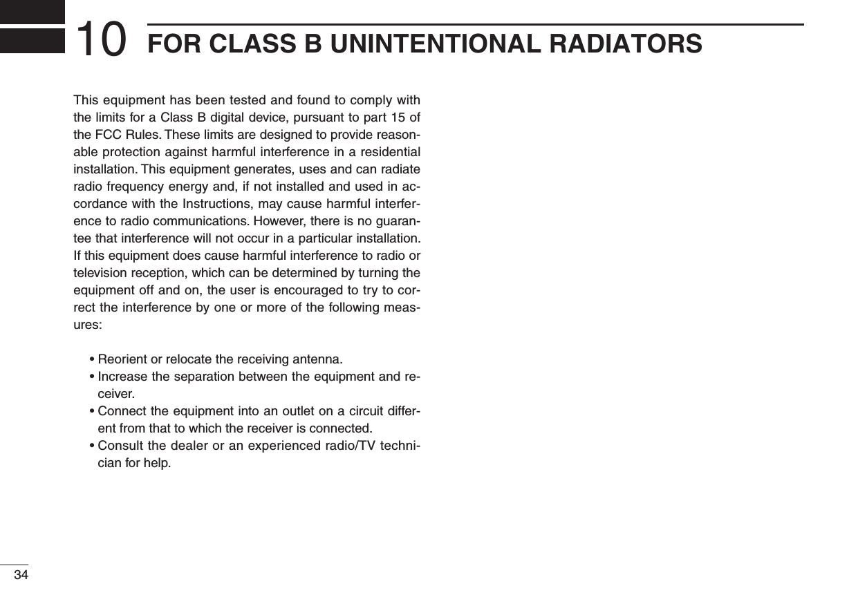
![72BASIC OPERATION 02■ Frequency setting exampleThe following example shows to how to set 126.40 MHz as the standby frequency and then exchange it with the active fre-quency indicator.The active frequency and the standby frequenies are exchanged.Previously used frequencies appear.Rotate the large tuning dial to change the standby frequency in MHz steps.Rotate the small tuning dial to change the standby frequency in kHz steps.121.805134.80RX126.805134.80RX126.405134.80RX134.805126.40RXqRotate [O-DIAL] clockwise to select “126” MHz.wRotate [DIAL] counterclockwise to select “400” kHz.ePush [�].NOTE: DO NOT hold down [�] continuously. Otherwise the sta- ndby frequency disappears. If this happens, hold down [�] until the standy frequency reappears. STEP DISPLAY NOTE](https://usermanual.wiki/ICOM-orporated/297400.User-Manual/User-Guide-1507287-Page-11.png)
![82BASIC OPERATION■ Direct frequency setting mode operationThe direct frequency setting mode operation is useful when setting a desired frequency directly as the active frequency.q Hold down [↔] for 2 seconds to enter the direct frequency setting mode. •Onlytheactivefrequencyisdisplayed.w Set an operating frequency. •Refertopages5,6indetails.e Push [RCL] or [↔] to exit the direct frequency setting mode.■ DualWatch operationThe DualWatch operation monitors the active frequency at certain intervals even when receiving a signal on the standby frequency. When a signal is received on the active frequency, the radio switches to the active frequency and stays on it until the signal disappears, irrespective of the standby frequency status.q Push [DUAL] to enter DualWatch operation. •“DUAL”appearsontheactivefrequencyindicator. •Theactiveorstandbyfrequency’s “RX” blinks when receiving a signal or opening the squelch.w Push [DUAL] again to exit DualWatch operation. •“DUAL”disappears.121.80RX129.405121.00RX DUAL RXATTENTION! During DualWatch operation, the standby frequency’s audio may be interrupted at the monitoring in-terval, but this is not a malfunction.](https://usermanual.wiki/ICOM-orporated/297400.User-Manual/User-Guide-1507287-Page-12.png)
![93MEMORY OPERATION 02 03■ Programming notesï Blank channelA memory or group channel with no frequency content is called as a blank channel. When a blank channel is selected while memory programming, “–––––” appears instead of a frequency.ï Memory protect functionIC-A210 has a memory protect function. The function pre-vents accidental changes or deletion.The function can be set in the MENU mode (p. 24).■ Entering memory mode•Push[RCL] to enter the memory mode.•Push[RCL] to set the selected memory channel frequency to the standby frequency, then exit the memory mode.•Holddown[RCL] for 2 seconds to exit the memory mode without changing the previously set standby frequency.■ Memory channel typeThere are five memory types*. The memory types are as fol-low:* Depends on versions, there are 4 memory types.ï Regular memory channel (MEMORY)There are up to 10 available memory channels. ï Group memory channel (GRP01–GRP20)There are up to 200 group channels, with 10 channels in each of 20 groups.ï Weather memory channel (WEATHER) (U.S.A. version ONLY)10 weather memory channels are available. They are used for monitoring NOAA (National Oceanic and Atmospheric Administration) broadcasts (reception of weather memory channels possible in U.S.A. version only).ï History memory channel (HISTORY)There are up to 10 available history memory channels. The active frequency is written into history memory channels automatically when pushing [↔] to exchange the active and standby frequency (except weather channels: U.S.A. version only).ï GPS memory channel (GPS)There are up to 10 available GPS memory channels.When connected to an external GPS receiver* equipped with an airport frequency database, the frequency data such as nearby airports can be transferred into GPS memory chan-nels.* Ask your dealer for available GPS receiver details.](https://usermanual.wiki/ICOM-orporated/297400.User-Manual/User-Guide-1507287-Page-13.png)
![103MEMORY OPERATION■ Programming a memory channelTo program the memory channels, follow the steps below.q Rotate [DIAL] and [O-DIAL] to set a desired frequency for the standby frequency.w Push [RCL] to enter the memory mode. •Thechannelnumberappears. •Thememorychannelnamealsoappearsifithasbeenentered.e Rotate [O-DIAL] to select a desired memory channel type. •Selectregularmemorychannelorgroupmemorychannel.r Push [MEM], and then rotate [O-DIAL] to select the “RE-PLACE” menu. •Thememorychannelnumberblinks.t Rotate [DIAL] to select a memory channel to be pro-grammed.y Push [MEM], to program the frequency into the channel. •“WRITECOMPLETED”appearsonthedisplaywhentheregu-lar memory channel is programmed.u Push [RCL] to exit the memory mode.■ Channel selectionThe transceiver has 10 channels in regular memory and 200 channels in the group memory. There are 10 channels in each of 20 groups (GRP01–GRP20).q Push [RCL] to enter the memory mode. •Thechannelnumberappears. •Thememorychannelnamealsoappearsifithasbeenentered.w Rotate [O-DIAL] to select the memory channel type. •Selectfromregularmemorychannelorgroupmemorychannel.e Rotate [DIAL] to select a desired memory channel number. Transferring the memory channel to the active fre-quency is necessary if you want to operate on the memory channel frequency. Refer to “Transferring memory contents” (p. 12) for details.r Push [RCL] to change to standby frequency to the se-lected memory channel frequency and exit the memory mode.CH01127.005122.00RX MEMORYNOTE: Hold down [RCL] for 2 seconds to exit the mem-ory mode without changing the previously set standby fre-quency.](https://usermanual.wiki/ICOM-orporated/297400.User-Manual/User-Guide-1507287-Page-14.png)
![113MEMORY OPERATION 03■ Programming exampleThe following is an example showing how to program 126.000 MHz into regular memory channel 4.“ ” appears when no frequency has been programmed into regular memory channel 4.“MEMORY” and the channel number appear.“126.00” appears in the standby display.126.005134.80RXCH01134.80RX MEMORYCH04134.80RX MEMORYCH04126.000---.---134.80RX MEMORYREPLACE ÇCH04126.005134.80RX MEMORYSet a “126.000 MHz” in the standby display.qPush [RCL], then rotate [O-DIAL] to select “MEMORY”.wPush [MEM], then rotate [O-DIAL] to select “REPLACE.”rPush [MEM] to store the desired frequency into the selected regular memory channel.tSelect regular memory channel 4 with [DIAL].e“WRITE COMPLETED” is displayed when the selected frequency is stored.Regular memory channel number blinks.TIP: Hold down [MEM] for 2 seconds to program a displayed frequency into any blank memory channel automatically, after step q.NOTE: The programming is cancelled if all regular memory channels have already programmed.](https://usermanual.wiki/ICOM-orporated/297400.User-Manual/User-Guide-1507287-Page-15.png)
![123MEMORY OPERATION■ Transferring memory contentsThis function transfers a memory channel’s contents into the active frequency display and places the previous active frequency into the standby display.q Push [RCL] to enter the memory mode. •Thechannelnumberappears. •Thememorychannelnamealsoappearsifithasbeenentered.w Rotate [O-DIAL] to select a desired channel type. •Selectregular,grouphistory,weather*orGPSmemorychan-nel. * Selectable depending on versions.e Rotate [DIAL] to select a memory channel to be trans-ferred.r Push [↔] to transfer the memory channel frequency into the active frequency display. •Thememorymodeisthencancelledautomatically.■ Memory mode menu ( Regular and group memory channels only)ï REPLACEReplacing the standby frequency with the memory channel frequency.ï DELETEDeletes the selected memory channel.ï REVIVEReturns the selected memory channel to its previous state.ï CH NAME (Regular memory channel only)Sets the channel name to the selected regular memory channel.ï GRP NAME (Group memory channel only)Sets the group name to the selected memory group.ï CH TAG (Group memory channel only)Sets the channel tag to the selected memory channel (Se-lecting the group memory channel is the only option).ï DONEReturn to the memory mode.CH01127.005122.00RX MEMORY122.005127.00RX MEMORYPush [↔].](https://usermanual.wiki/ICOM-orporated/297400.User-Manual/User-Guide-1507287-Page-16.png)
![133MEMORY OPERATION 03■ Regular memory channelThe transceiver has 10 regular memory channels. Five programming options are selectable.The following functions are available.REPLACE, DELETE, REVIVE and CHANNEL NAME EDIT functions.q Push [RCL] to enter the memory mode. •Thechannelnumberappears. •Thememorychannelnamealsoappearsifithasbeenentered.w Rotate [O-DIAL] to select the regular memory channel. •“MEMORY”appears.e Rotate [DIAL] to select a desired channel.r Push [MEM], then rotate [O-DIAL] to select a menu op-tion as follow. •Thememorychannelnumberblinks.t Push [MEM] to perform the selected action.■ Group memory channelThe transceiver has 200 group memory channels comprised of 10 channels in each of 20 groups.The following functions are available.REPLACE, DELETE, REVIVE GROUP NAME EDIT and CHANNEL TAG functions.q Push [RCL] to enter the memory mode. •Thechannelnumberappears. •Thememorychannelnamealsoappearsifithasbeenentered.w Rotate [O-DIAL] to select the group memory channel number. •Agroupnumber“GRP01–GRP20”appears.e Push [DIAL], and then rotate [O-DIAL] to select the memory group from GRP01 to GRP20 if necessary. •Thegroupandchannelnumbersblink. •Push[DIAL] again, or push [RCL] to set the memory group.r Rotate [DIAL] to select a desired channel within the se-lected group.t Push [MEM], rotate [O-DIAL] to select a menu as follows. •Thememorychannelnumberblinks.y Push [MEM] to perform the selected action.CH01127.005122.00RX GRP01CH01127.005122.00RX MEMORYREPLACE Replace to the standby frequency.DELETE Delete the memory channel.REVIVE Revive the previous memory channel data.CH NAME Edit the memory channel name.DONE Do nothing and return to the memory mode.REPLACE Replace to the standby frequency.DELETE Delete the memory channel.REVIVE Revive the previous memory channel data.GRP NAME Edit the group name.CH TAG Set the memory channel as a tag channel.DONEDo nothing and return to the memory mode.](https://usermanual.wiki/ICOM-orporated/297400.User-Manual/User-Guide-1507287-Page-17.png)
![143MEMORY OPERATION■ History memory channelThe transceiver has 10 history memory channels.The standby frequency is stored into a history memory chan-nel when pushing [↔].The frequency is stored into the history memory channel in order from “CH01” to “CH10.”q Push [RCL] to enter the memory mode. •Thechannelnumberappears. •Thememorychannelnamealsoappearsifithasbeenentered.w Rotate [O-DIAL] to select the history memory channel. •“HISTORY”appears.e Rotate [DIAL] to select a desired channel. •Push[↔] to exchange the history memory channel frequency to the active frequency if necessary.r Push [RCL] to exit the memory mode.■ Clearing the memory contents ( Regular and group memory channels only)Unwanted memory channels can be cleared.q Push [RCL] to select memory mode. •Thechannelnumberappears. •Thememorychannelnamealsoappearsifithasbeenentered.w Rotate [O-DIAL] to select the memory channel type. •Selectfromregularmemorychannelorgroupmemorychannel.e Rotate [DIAL] to select a desired channel.r Push [MEM], then rotate [O-DIAL] to select “DELETE.” •Thememorychannelnumberblinks.t Push [MEM] to delete the memory channel data. •“------------”appearsmomentarily,thenthenextselectablechannel appears.y Push [RCL] to exit the memory mode.CH01127.005122.00RX HISTORYCH01127.000127.000122.00RX MEMORYÅDELETE ÇCH01122.00RX MEMORYNOTE: Instead of steps r and t, holding down [MEM] for 2 seconds after step e also allows delete or revive op-eration.](https://usermanual.wiki/ICOM-orporated/297400.User-Manual/User-Guide-1507287-Page-18.png)
![153MEMORY OPERATION 03■ Programming channel names (Regular memory channel only)The regular memory channel can display a six character name in addition to the memory number.q Push [RCL] to enter the memory mode, then rotate [O-DIAL] to select a desired regular memory channel in the memory mode.w Rotate [DIAL] to select a desired channel.e Push [MEM], then rotate [O-DIAL] to select “CH NAME.”r Push [MEM]. The memory channel name’s 1st digit blinks.t Rotate [DIAL] to select a desired character. •Thecharactertypeasshownbelowisselectable. •Push[DIAL]toswitchfromcapitalletters(A,B,C,···)→ lower case (a, b, c, ···) → number (0, 1, 2, ···) → then again to capital letters (A, B, C, ···) in sequential order.y Rotate [O-DIAL] to select the next input digit.u Repeat t–y to input the memory channel name.i Push [MEM] to set the memory channel name.•Selectable characters■ Programming group names (Group memory channel only)The memory groups can display a six character name in ad-dition to the group number (“GRP01”–“GRP20”).q Push [RCL], then rotate [O-DIAL] to select a desired memory channel in the memory mode. •Rotate[O-DIAL] to select the memory channel type if neces-sary.w Push [DIAL], and then rotate [O-DIAL] to select the memory group from GRP01 to GRP20, if necessary. •Push[DIAL] again to set the memory group.e Push [MEM], then rotate [O-DIAL] to select “GRP NAME.”r Push [MEM], and the group name’s 1st digit blinks.t Rotate [DIAL] to select a desired character. •Thecharactertypeasshownleft“Selectablecharacters”areselectable. •Push[DIAL]toswitchfromcapitalletters(A,B,C,···)→ lower case (a, b, c, ···) → number (0, 1, 2, ···) → then again to capital letters (A, B, C, ···) in sequential order.y Rotate [O-DIAL] to select the next input digit.u Repeat t–y to input the group name.i Push [MEM] to set the group name.0 1 2 3 4 5 6 7 8 9 : ; < = > ? @ A B C D E F G H I J K L M N O P Q R S T U V W X Y Z [ \ ] ^ _ `a b c d e f g h i j k l m n o p q r s t u v w x y z { | } ~ ■ ! ” # $ % & ’ ( ) ∗ + , – . /](https://usermanual.wiki/ICOM-orporated/297400.User-Manual/User-Guide-1507287-Page-19.png)
![163MEMORY OPERATION■ Programming channel tag (Group memory channel only)The tag name can be set a three character name in addition to the group number. It is convenient for separating memory type.q Push [RCL], then rotate [O-DIAL] to select a desired group memory channel in the memory mode. •Rotate[O-DIAL] to select the memory channel type if neces-sary.w Push [MEM], then rotate [O-DIAL] to select “CH TAG” when selecting “LABEL” in “Group memory channel dis-play” of the menu mode (p. 24)e Push [MEM], then rotate [DIAL] to select a desired chan-nel tag. •Thetagtypeasshownbelowisselectable.r Push [MEM] to set the channel tag.• Selectable tags___ / TWR / GND / ATS / ATF / APP / ARR / AWS / CLR / CTF / DEP / FSS / RFS / UNI / MF / OTH / U-1 / U-2■ Channel tag list*1Group memory, *2GPS memoryCH01127.005122.00RX GRP01TWRTAG NAMEDISPLAY MEANSGroup*1GPS*2_ _ _ YES – Non-tagTWR YES YES TowerGND YES YES GroundATS YES YES ATISATF YES YES Air trafficAPP YES YES ApproachARR YES YES ArrivalAWS YES YES Automatic Weather StationCLR YES YES Clearance / DeliveryCTF YES YESCommon Traffic Advisory FrequencyDEP YES YES Departure FrequencyFSS YES YES Flight Service StationRFS YES YES Remote Flight Service StationUNI YES YES Unicom frequencyMF YES YES Mandatory frequencyOTH YES – OtherU-1 YES – User1 setting (Refer to page 26)U-2 YES – User2 setting (Refer to page 26)](https://usermanual.wiki/ICOM-orporated/297400.User-Manual/User-Guide-1507287-Page-20.png)
![173MEMORY OPERATION 03■ GPS memoryWhen connected to an external GPS receiver* equipped with an airport frequency database, frequency data such as nearby airports can be transferred and made available in the GPS memory (maximum 10-memory channels).*Ask your dealer for available GPS receiver details.q Push [RCL] to enter the memory mode. •Thechannelnumberappears.w Rotate [O-DIAL] to select the GPS memory channel. •“GPS”appears.e Rotate [DIAL] to select a desired channel.r Push [RCL] to exit the GPS memory mode.■ Weather memory channel (U.S.A. version only)The U.S.A. version has VHF marine WX (weather) channel receiving capability for flight planning.q Push [RCL] to enter the memory mode. •Thechannelnumberappears.w Rotate [O-DIAL] to select the weather memory channel. •“WEATHER”appears.e Rotate [DIAL] to select a desired channel.r Push [RCL] to exit the weather memory mode.WX01162.555122.00RX DUAL WEATHERCH01 TWR122.055122.00RX GPS RJTJAirport codeTag name• Weather memory channel listNOTE: •SeetheGPSreceiver’sinstructionmanualfortransferringthe frequency data.•AskyourdealerforavailableGPSreceiverdetails.Channel Frequency Channel FrequencyWX01 162.550 MHz WX06 162.500 MHzWX02 162.400 MHz WX07 162.525 MHzWX03 162.475 MHz WX08 161.650 MHzWX04 162.425 MHz WX09 161.775 MHzWX05 162.450 MHz WX10 163.275 MHz](https://usermanual.wiki/ICOM-orporated/297400.User-Manual/User-Guide-1507287-Page-21.png)
![183MEMORY OPERATION■ GPS memory editThe received GPS memory data is stored in the desired group memory channel.q Push [RCL] to enter the memory mode. •Thechannelnumberappears. •Thememorychannelnamealsoappearsifithasbeenentered.w Rotate [O-DIAL] to select the GPS memory channel. •“GPS”appears.e Push [MEM] to enter the GPS memory channel edit mode, then rotate [O-DIAL] to select a desired group memory. •“GPS”andairportcodeblink.r Push [MEM] to store the GPS memory channel data to the selected group memory.t Push [RCL] to exit the memory mode.NOTE:The GPS memory data is overwritten if the se-lected GPS memory channel already contains other data.■ Memory protectionThe transceiver has memory protection which inhibits to the editing (storing, deleting, replacing, etc.) of the memory group memory channels.Refer to “Memory Protection” (p. 24) for details.](https://usermanual.wiki/ICOM-orporated/297400.User-Manual/User-Guide-1507287-Page-22.png)
![194OTHER FUNCTIONS 03 04■ Lock functionThe lock function prevents accidental frequency changes and accidental function activation.q Hold down [DIAL] for 2 seconds to turn the lock function ON. •“OD” appears when DIAL lock mode is selected. •“OP” appears when PANEL lock mode is selected.w To turn the function OFF, repeat step q above. •“OD” or “OP” disappears.■ Accessing 121.5 MHz emergency frequencyThe IC-A210 can be set to the 121.5 MHz emergency fre-quency quickly. This function can be activated even when the key lock function is in use.q Push [EC] to call the emergency frequency to the standby frequency, and enter the DualWatch operation automati-cally.w Push [↔] to transfer emergency frequency to the active frequency if necessary. •“EC”appears.e Push [↔] to exit from the emergency frequency. •Setthefrequencyexcept121.500MHzbeforepushing[↔] to the standby frequency if necessary. •“EC”disappears.NOTE: “EC” also appears on the display while the active frequency is set to 121.500 MHz.NOTE: AUTOMATIC LOCK RELEASE FUNCTIONThis transceiver has an “Automatic Lock Release Function” which releases the Lock function automatically when an operator gets into a panic.The lock function is released when pushing any keys (ex-cept [EC]) eight times or rotating any dials (except [VOL]) 25-clicks for 5 seconds.CONVENIENT!: Hold down [EC] for 2 seconds to enter the direct frequency setting mode (p. 8), and set the emer-gency frequency (121.5 MHz).•“EC”appears.](https://usermanual.wiki/ICOM-orporated/297400.User-Manual/User-Guide-1507287-Page-23.png)
![204OTHER FUNCTIONS■ Intercom functionWhen two headphone and microphone jacks are connected to the transceiver, these headsets can be used as a voice-activated intercom.q Enter to the MENU mode. •Seepage22fordetails.w Set Intercom Usable Setting to ON. •Seepage26fordetails.e Exit from the MENU mode. •Seepage22fordetails.r Hold down [DUAL] for 2 seconds to enable the intercom function. •“ICS”appears.•Theheadphoneaudiooutputlevelcanbeselected“OFF,” “output level fixing (001–080)” or “interlocking with [VOL]” in the MENU mode (p. 23).•Themicrophone1andmicrophone2audioinputlevelscan be also selected “OFF” or “output level fixing (001–080)” in the MENU mode (p. 23).■ Squelch test functionThis function opens the squelch manually for testing.q Push [VOL] to turn the squelch test function ON. •“TEST”appears.w To turn the function OFF, repeat step q as above. •“TEST”disappears.■ Frequency step settingFrequency step (8.33 kHz or 25 kHz) is selectable in the menu mode.q Enter the menu mode (See page 22 for details).w Rotate [O-DIAL] to select the “FREQ. STEP (Frequency step).”e Rotate [DIAL] to select the desired frequency step (8.33 kHz or 25 kHz).r Push [RCL] to exit MENU mode, and returning to the pre-vious operating condition.](https://usermanual.wiki/ICOM-orporated/297400.User-Manual/User-Guide-1507287-Page-24.png)
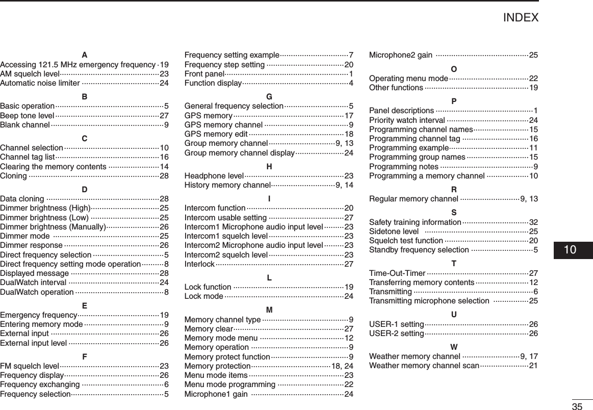
![214OTHER FUNCTIONS■ Weather memory channel scan (U.S.A. version only)Scanning searches for weather channel signals automati-cally and makes it easier to listen purposes.Repeatedly scans all weather memory channels.This function is available for the U.S.A. version only.q Set to the weather memory channel mode.w Hold down [VOL] for 2 seconds to start weather memory channel scan. •Tochangethescandirection,turn[DIAL]. •“NOWTH”appearswhennosignalreceivesfromWX01–WX10 channels. Then the weather memory channel scan stops automatically. •“SEARCH“asheswhilescanning.e Hold down [VOL] for 2 seconds again to stop the scan.162.555122.00RX WEATHERSEARCH 04](https://usermanual.wiki/ICOM-orporated/297400.User-Manual/User-Guide-1507287-Page-25.png)
![225MENU MODE■ MENU mode programmingMENU mode is available at power ON and allows you to set seldom-changed settings. In this way you can customize transceiver operations to suit your preferences and operating style.D Operating MENU modeq Rotate [VOL] to turn the transceiver’s power ON.w Push [RCL] to set VFO mode if memory mode is se-lected.e Hold down [RCL] for 2 seconds to enter the MENU mode.r Rotate [O-DIAL] to select setting items.t Rotate [DIAL] to select a desired setting.y Push [RCL] to exit MENU mode, and returning to the pre-vious operating mode.• MENU mode itemsMENU MODEHP LEVEL AF GAIN01/31RCLMEMOFFVOLPUSHTESTCOMMDUALECiA210AF GAINOFF001076Desired condition settingHP LEVELINCOM LV1INCOM LV2MIC1 SQLMenu mode items settingMenu mode items Items numberSetting valuep. 23HP LEVELGRP MEMORYINCOM LV2INCOM LV1MIC1 SQLMIC2 SQLANLSQL LEVELFM SQL LV**Not available on all versions.LOCK MODEDW INTERVALPRI. WATCHMEM PROTECTMIC2 GAINMIC1 GAINSIDETONE LVDISP HIGHDISP MAN.AUX LEVELDISP MODEDISP LOWDISP RESP.FREQ DISPU-1 ID SETU-2 ID SETAUX INBEEPINCOM MODETIME OUTINTERLOCKMEM CLEARp. 26p. 27p. 25p. 25p. 24TX MIC SELFREQ. STEP](https://usermanual.wiki/ICOM-orporated/297400.User-Manual/User-Guide-1507287-Page-26.png)
![235MENU MODE■ MENU mode itemsD AM Squelch Level “SQL LEVEL”Set the squelch level for AM mode operation.In order to receive signals properly, as well as for the scan to function effectively, the squelch must be adjusted to the proper level.•–010–010:SettingAMsquelchlevelfrom–10to+10.D FM Squelch Level “FM SQL LV” (U.S.A. version only)Set the squelch level for FM mode operation.•–010–010:SettingFMsquelchlevelfrom–10to10.D Headphone Level “HP LEVEL”Set the headphone output level while receiving.•AFgain :Theoutputlevelissameas[VOL].•OFF(0) :Mutestheheadphone.•001–080 :Setsaudiolevelfrom1to80.D Intercom1 Microphone Audio Input Level “INCOM LV1”Set the intercom1 microphone input level.•OFF(0) :Mutestheintercom1microphone.•001–080 :Setstheintercom1inputlevelfrom1to80.D Intercom2 Microphone Audio Input Level “INCOM LV2”Set the intercom2 microphone input level.•OFF(0) :Mutestheintercom2microphone.•001–080 :Setstheintercom2inputlevelfrom1to80.D Intercom1 Squelch Level “MIC1 SQL”Set the intercom1 squelch level.The setting level is required to open the squelch when speaking to the intercom1.•OFF(0) :Turnsofftheintercom1squelch.•001–030 :Setstheintercom1squelchlevelfrom1to30.D Intercom2 Squelch Level “MIC2 SQL”Set the intercom2 squelch level.The setting level is required to open the squelch when speaking to the intercom2.•OFF(0) :Turnsofftheintercom2squelch.•001–030 :Setstheintercom2squelchlevelfrom1to30. 05](https://usermanual.wiki/ICOM-orporated/297400.User-Manual/User-Guide-1507287-Page-27.png)
![245MENU MODE■ MENU mode items (Continued)D Automatic Noise Limiter “ANL”The ANL (Automatic Noise Limiter) function reduces noise components such as that caused by engine ignition systems while receiving.•OFF :ANLfunctionOFF.•ON :ANLfunctionON.D Lock Mode “LOCK MODE”Set the lock function.•OFF :ThelockfunctionisOFF.•DIAL :Thelockfunctionappliesto[DIAL].•PANEL :Thelockfunctionappliestobuttonsonthefrontpanel.D DualWatch Interval “DW INTERVAL”Set the interval time while operating DualWatch or weather scan.•FAST :Setstheintervaltimeto300milliseconds.•MID :Setstheintervaltimeto600milliseconds.•SLOW :Setstheintervaltimeto2seconds..D Priority Watch Interval “PRI. WATCH”Set the active frequency receive interval time while receiving the standby frequency.•FAST :Setstheintervaltimeto400milliseconds.•MID :Setstheintervaltimeto800milliseconds.•SLOW :Setstheintervaltimeto2seconds.D Memory Protection “MEM PROTECT”Set the memory protection to regular memory channels and group memory channels.Editing the regular memory and group memory channels is inhibited while the protection is ON.•OFF :ThememoryprotectionisOFF.•ON :ThememoryprotectionisON.D Group Memory Channel Display “GRP MEMORY”Set the displaying whether the label displays or not.•CH :Onlythechannelnumberisdisplayed.•LABEL :Thelabelisalsodisplayed.D Microphone1 Gain “MIC1 GAIN”Set the microphone1’s gain.•–010–010:Settingthemicrophone1’sgainfrom–10to+10.NOTE: The priority watch interval does not appear when the “PRIORITY WATCH” is set to “OFF”, by the CS-A210.](https://usermanual.wiki/ICOM-orporated/297400.User-Manual/User-Guide-1507287-Page-28.png)
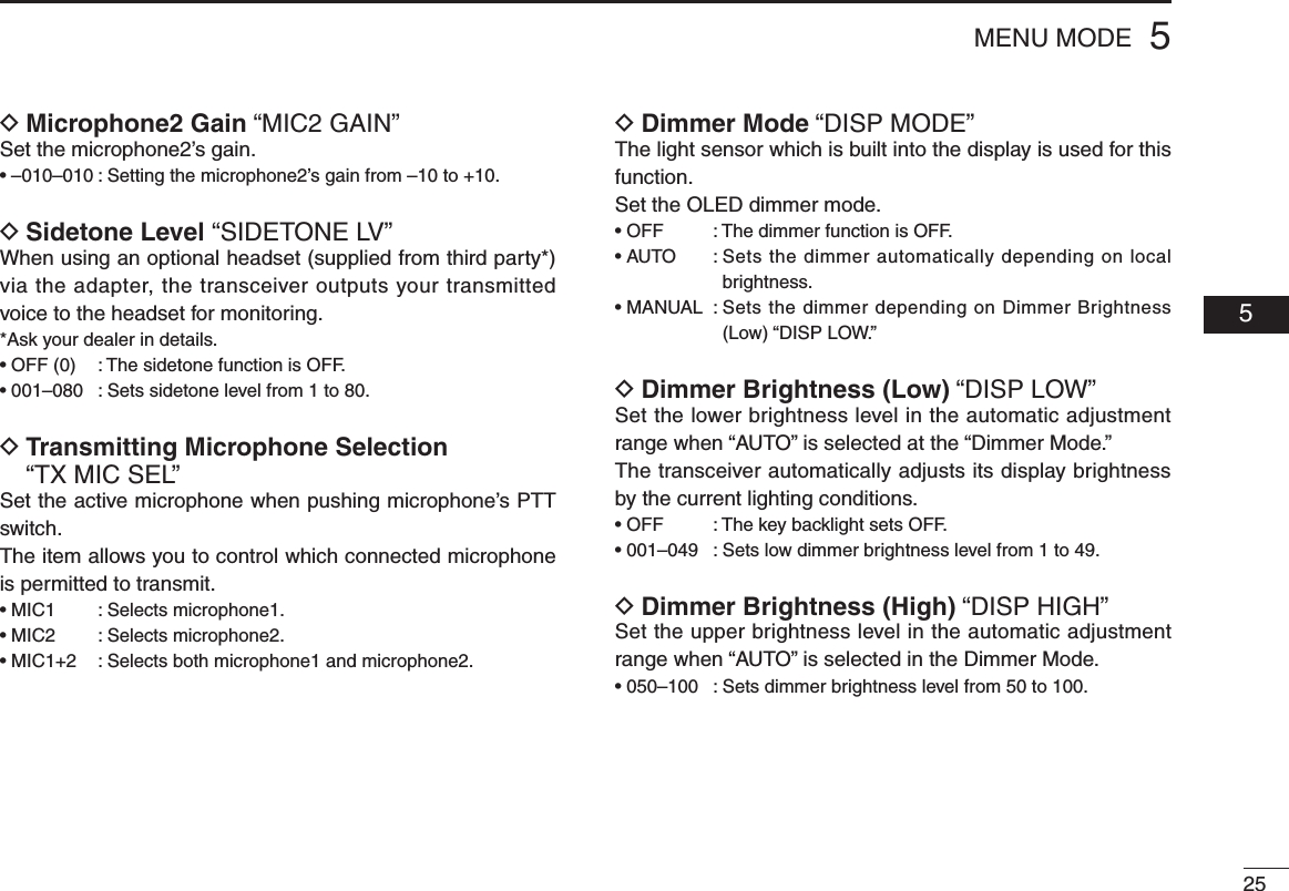
![265MENU MODE■ MENU mode items (Continued)D Dimmer Brightness (Manually) “DISP MAN.”Set the brightness manually to suit your own preferences.•000–100 :Settingdimmerlevelmanuallyfrom0(OFF)to100.D Dimmer Response “DISP RESP.”Set the dimmer switching speed when selecting “AUTO” at the “Dimmer Mode.”•STANDARD :Selectsnormalswitchingspeed.•FAST :Selectsfastswitchingspeed.D Frequency Display “FREQ DISP”Set the 1 kHz digit frequency displaying in the OLED.•OFF :The1kHzdigitisnotdisplayedintheOLED.•ON :The1kHzdigitisalwaysdisplayedintheOLED.•ZEROSUPP. :The1kHzisdigitdisplayontheOLEDas0.D USER-1 Setting “U-1 ID SET”Set the USER-1, channel tag, to a desired ID.q Push [MEM] to enter the U-1 ID edit mode.w Rotate [DIAL] to select a desired character.e Rotate [O-DIAL] to select the next input digit.r Repeat w–e to input the U-1 ID.t Push [MEM] again to store the U-1 ID, and exit the edit mode.D USER-2 Setting “U-2 ID SET”Set the USER-2, channel tag, to a desired ID.q Push [MEM] to enter the U-2 ID edit mode.w Rotate [DIAL] to select a desired character.e Rotate [O-DIAL] to select the next input digit.r Repeat w–e to input the U-2 ID.t Push [MEM] again to store the U-2 ID, and exit the edit mode.D External Input “AUX IN”Set the external input mode.•OFF :TheexternalinputisOFF.•ON :Theexternalinputisavailablewhilethesquelchisclosed.•INCOM :Theexternalinputisavailablewiththeintercomopera-tions as following. - The intercom function is OFF. - While the intercom function is not in use. - While an audio signal is not input into the intercom’s microphone.D External Input Level “AUX LEVEL”Set the external input level.•OFF(0) :Theexternalinputdoesnotoperate.•001–080 :Setstheexternalinputlevelfrom1to80.•AFGAIN :Interlockedwith[VOL].](https://usermanual.wiki/ICOM-orporated/297400.User-Manual/User-Guide-1507287-Page-30.png)
![275MENU MODED Beep Tone Level “BEEP”Confirmation beep tones normally sound when storing mem-ory, operating time-out-timer function, etc. These can be set a desired beep level as you prefer.•OFF(0) :ThebeeptoneturnsOFF.•001–100 :Settingthebeeptonelevelfrom1to100.D Intercom Usable Setting “INCOM MODE” Set the intercom using or not.•ON :Theintercomisusable.•OFF :Theintercomisunusable.D Time-Out-Timer “TIME OUT”To prevent accidental prolonged transmission, the trans-ceiver has a time-out-timer function. This timer starts when a transmission begins, and will cut off the transmission when the time set in the timer elapses.•020–240 :Settingtime-out-timerstartingperiodfrom20secondsto 240 seconds in 10 secons intervals.D Frequency Step “FREQ. STEP”Set the desired frequency step: 8.33 kHz or 25 kHz.•25kHz :Settingthefrequencystepto25kHz.•8.33kHz :Settingthefrequencystepto8.33kHz.D Interlock “INTERLOCK”When two transceivers are connected together, the interlock function can prevent them from transmitting at the same time.•TXINHIBIT :Transmissionisprevented.•RXMUTE :Audiooutputisprevented.•BOTH :Transmissionandaudiooutputarebothprevented.D Memory Clear “MEM CLEAR”Set values in the CPU are cleared.Hold down [MEM] for 2 seconds, the CPU is reset as follows.•MENU :MENUmodeitemsarereset.•MEMORY :Storedmemoriesarereset.•ALL :AllCPUdataisreset. 05NOTE: When using an external speaker, the beep tone level when the squelch is closed is fixed and cannot be changed in the MENU mode. NOTE: The interlock does not appear when the “TX/RX INTERLOCK SW” is set to “DISABLE,” by the CS-A210.](https://usermanual.wiki/ICOM-orporated/297400.User-Manual/User-Guide-1507287-Page-31.png)