ICOM orporated 300900 HF/50 MHz Transceiver User Manual IC 7700 ENG
ICOM Incorporated HF/50 MHz Transceiver IC 7700 ENG
UserManual.wiki
>
ICOM orporated
>
300900 User Manual
>
User Manual Part 1
Contents
1.
User Manual Part 1
2.
User Manual Part 2
User Manual Part 1
Navigation menu
Upload a User Manual
Namespaces
Wiki Guide
HTML
PDF
Info
Views
User Manual
Discussion / Help
Navigation
![iiPRECAUTIONSRWARNING HIGH RF VOLTAGE! NEVERattach an antenna or internal antenna connector duringtransmission. This may result in an electrical shock orburn.RWARNING! NEVER operate the transceiverwith a headset or other audio accessories at high vol-ume levels. Hearing experts advise against continuoushigh volume operation. If you experience a ringing inyour ears, reduce the volume or discontinue use.RWARNING! Immediately turn the transceiverpower OFF and remove the power cable if it emits anabnormal odor, sound or smoke. Contact your Icomdealer or distributor for advice.RCAUTION! NEVER put the transceiver in anyunstable place (such as on a slanted surface or vi-brated place). This may cause injuly and/or damage tothe transceiver.RCAUTION! NEVER put the transceiver’s rearpanel side down after lifting up the transceiver by hold-ing rack mounting handle. This may scratch the sur-face of the place or damage the connectors on thetransceiver’s rear panel.RCAUTION! NEVER change the internal set-tings of the transceiver. This may reduce transceiverperformance and/or damage to the transceiver.In particular, incorrect settings for transmitter circuits,such as output power, idling current, etc., might dam-age the expensive final devices.The transceiver warranty does not cover any problemscaused by unauthorized internal adjustment.RCAUTION! NEVER touch the transceiver topcover when transmitting continuously for long periods.The top cover may be hot.RCAUTION! NEVER let metal, wire or other ob-jects protrude into the transceiver or into connectorson the rear panel. This may result in an electric shock.RCAUTION! NEVER block any cooling vents onthe top, rear or bottom of the transceiver.RCAUTION! NEVER expose the transceiver torain, snow or any liquids.RCAUTION! NEVER install the transceiver in aplace without adequate ventilation. Heat dissipationmay be reduced, and the transceiver may be dam-aged.RCAUTION! NEVER operate or touch the trans-ceiver with wet hands. This may result in an electricshock or damage to the transceiver.RCAUTION! The transceiver weighs approx. 22.5kg (50 lb). Always have two people available to carry,lift or turn over the transceiver. RCAUTION! The line-voltage receptacle must benear the transceiver and must be easily accessible.Avoid extension cords.DO NOTuse chemical agents such as benzine or al-cohol when cleaning the IC-7700, as they can damagethe transceiver’s surfaces.DO NOT push the PTT switch when you don’t actu-ally desire to transmit.AVOID using or storing the transceiver in areas withtemperatures below ±0°C (+32°F) or above +50°C(+122°F).AVOID placing the transceiver in excessively dusty en-vironments or in direct sunlight.AVOID placing the transceiver against walls or puttinganything on top of the transceiver. This may overheatthe transceiver.Always place unit in a secure place to avoid inadver-tent use by children.BE CAREFUL! If you use a linear amplifier, set thetransceiver’s RF output power to less than the linearamplifier’s maximum input level, otherwise, the linearamplifier will be damaged.Use Icom microphones only (supplied or optional).Other manufacturers’ microphones have different pinassignments, and connection to the IC-7700 may dam-age the transceiver or microphone.The LCD display may have cosmetic imperfections thatappear as small dark or light spots. This is not a mal-function or defect, but a normal characteristic of LCDdisplays.During maritime mobile operation, keep the transceiverand microphone as far away as possible from the mag-netic navigation compass to prevent erroneous indica-tions.Turn [I/O] switch (on the rear panel) OFF and/or dis-connect the AC power cable from the AC outlet whenyou will not use the transceiver for long period of time.For U.S.A. onlyCAUTION: Changes or modifications to this device,not expressly approved by Icom Inc., could void yourauthority to operate this device under FCC regulations.](https://usermanual.wiki/ICOM-orporated/300900.User-Manual-Part-1/User-Guide-900712-Page-4.png)
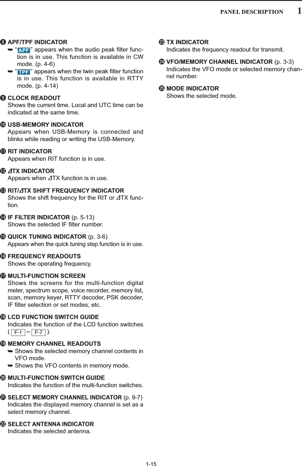
![1-2qPOWER SWITCH (p. 3-2)➥Push to turn the transceiver power ON.• The [POWER] indicator above this switch lights greenwhen powered ON.➥Push and hold for 1 sec. to turn the transceiverpower OFF.• The [POWER] indicator lights orange when the trans-ceiver is OFF when the internal power supply isswitched ON.wTRANSMIT SWITCH Selects transmit or receive.• The [TX] indicator lights red while transmitting and the[RX] indicator lights green when the squelch is open.eANTENNA TUNER SWITCH (p. 10-6)➥Turns the internal antenna tuner ON and OFF(bypass) when pushed momentarily.• The [TUNER] indicator above this switch lights greenwhen the tuner is turned ON, goes off when tuner isturned OFF (bypassed).➥Tunes the antenna tuner manually when pushedand held for 1 sec.• The [TUNER] indicator blinks red during manual tun-ing.• When the tuner cannot tune the antenna, the tuningcircuit is bypassed automatically after 20 sec.rTIMER SWITCH (p. 11-4)➥Turns the sleep or daily timer function ON andOFF.• The [TIMER] indicator above this switch lights greenwhen the timer is in use.➥Enters timer set mode when pushed and held for1 sec.tHEADPHONE JACK [PHONES]Accepts standard stereo headphones.• Output power: 5 mW with an 8 load.• When headphones are connected, the internal speakeror connected external speaker does not function.yELECTRONIC KEYER JACK [ELEC-KEY] (p. 2-5)Accepts a paddle to activate the internal electronickeyer for CW operation.• You can select internal electronic keyer, bug-key orstraight key operation in keyer set mode. (p. 4-12)• A straight key jack is located on the rear panel. See [CWKEY] on p. 1-12.• Keyer polarity (dot and dash) can be reversed in keyerset mode. (p. 4-12)• 4-channel memory keyer is available for your conve-nience. (p. 4-8)TIMERTUNERTRANSMITPOWER(dot)(com)(dash)Turn the internal power supply ON in first. The in-ternal power supply switch is located on the rearpanel. (p. 3-2)1PANEL DESCRIPTIONPOWERTUNERTIMERVOXSSB CWRTTY/PSKAM/FM DATA AUTOTUNEXFCM.SCOPEEXIT/SETRECPLAYVOICE MEMORYBRIGHTCONTRASTVOX GAINMONI GAINCOMPDRIVE ANTI VOXBK-IN MONITORTRANSMITMICELEC-KEYPHONESAF RFMIC RF PWRKEY SPEEDDELAYF-1 F-2 F-3 F-4 F-5 F-6 F-7LOCKTX RX SPLITAGC VRNR11.8 3.5410 14721 24MPMAGENE50NBAGC SQL NR NBqwertyu!5io!0 !1 !2 !3 !4!6■Front panel](https://usermanual.wiki/ICOM-orporated/300900.User-Manual-Part-1/User-Guide-900712-Page-13.png)
![1-3uMICROPHONE CONNECTOR [MIC]Accepts an optional microphone.• See p. 15-4 for appropriate microphones.• See p. 2-10 for microphone connector information.iMIC GAIN CONTROL [MIC] (p. 3-12)Adjusts microphone input gain.• The transmit audio tone in SSB, AM and FM modes canbe adjusted independently in set mode. (p. 12-5)✔How to set the microphone gain.Set the [MIC] control so that the ALC meter occasionallymoves up-scale during normal voice transmission in SSB,AM or FM mode.oVOX SWITCH ➥Push to turn the VOX function ON and OFF dur-ing SSB, AM and FM mode operation. (p. 6-2)➥Push and hold for 1 sec. to enter VOX set mode.(p. 6-2)✔What is the VOX function?The VOX function (voice operated transmission) activatestransmission without pushing the transmit switch or PTTswitch when you speak into the microphone; then auto-matically returns to receive when you stop speaking.!0 RF POWER CONTROL [RF PWR] (p. 3-12)Continuously varies the RF output power from min-imum (5 W*) to maximum (200 W*).*AM mode: 5 W to 50 W!1 BREAK-IN SWITCH Push to turn the break-in function ON (semi-break-in,full-break-in) and OFF during CW mode operation.(p. 6-3)✔What is the break-in function?The break-in function switches transmit and receive withCW keying. Full break-in (QSK) can monitor the receivesignal between CW dots and dashes.!2 ELECTRONIC CW KEYER SPEED CONTROL[KEY SPEED] (p. 4-4)Adjusts the internal electronic CW keyer’s speed.• 6 wpm (min.) to 48 wpm (max.) is the available range.!3 MONITOR SWITCH (p. 6-4)Monitors your transmitted IF signal.• The CW sidetone functions regardless of switch setting in CW mode.• The [MONITOR] indicator above this switch lights greenwhile the function is activated.!4 BREAK-IN DELAY CONTROL [DELAY] (p. 6-3)Adjusts the transmit-to-receive switching delay timefor CW semi-break-in operations.!5 AGC CONTROL [AGC] (p. 5-11)Adjusts the continuously-variable AGC circuit timeconstant.• To use [AGC] control, push ([AGC VR] indi-cator lights).!6 SQUELCH CONTROL [SQL] (outer control; p. 3-9)Adjusts the squelch threshold level. The squelchmutes noise output from the speaker (closed condi-tion) when no signal is received.• The squelch is particularly effective for FM. It is alsoavailable in other modes.• The 11 to 12 o’clock position is recommended for themost effective use of the [SQL] control.AGC VRMONITORMONITORBK-INVOXDeepDeepNoise squelchSquelchthresholdShallowShallowS-metersquelchSquelch is openSlowFastLong delay forslow speed keyingShort delay forhigh speed keyingMax.48 wpmMin.6 wpmIncreasesDecreasesRecommended level foran Icom microphoneDecreasesDecreases IncreasesIncreases1PANEL DESCRIPTION](https://usermanual.wiki/ICOM-orporated/300900.User-Manual-Part-1/User-Guide-900712-Page-14.png)
Adjusts the DSP noise reduction level when thenoise reduction function is in use. Set for maximumreadability.• To use this control, push .!8 NOISE BLANKER CONTROL [NB](outer control; p. 5-16)Adjust the noise blanker threshold level.• To use this control, push .!9 AGC VOLUME SWITCH (p. 5-11)➥Push to toggle [AGC] control usage ON and OFF.• Use [AGC] control to set the AGC time constant whenswitched ON.• The [AGC VR] indicator above this switch lightsgreen when the control is ON.➥Turns the AGC function OFF when pushed andheld for 1 sec.@0 USB (Universal Serial Bus) CONNECTOR [USB](p. 2-4)➥Insert USB-Memory* for both reading/storing awide variety of the transceiver’s information anddata.• The indicator above the connectors lights or blinkswhen the transceiver reads or writes to the memorydata.• Unmount operation is necessary before removing theUSB-Memory* (p.12-25).➥Connects a PC keyboard for RTTY and PSK31operations.• USB keyboard* is supported.*: USB-Memory or USB keyboard is not supplied byIcom.@1 NOISE REDUCTION SWITCH (p. 5-17)Push to switch DSP noise reduction ON and OFF.• The [NR] indicator above this switch lights green whenthe function is activated.@2 AF CONTROL [AF] (inner control; p. 3-9)Varies the audio output level of the speaker orheadphones.NRAGC VRNBNRAudio outputincreasesAudio outputdecreasesDeepShallowIncreasesDecreases1PANEL DESCRIPTIONPOWERTUNERTIMERVOXSSB CWRTTY/PSKAM/FM DATA AUTOTUNEXFCM.SCOPEEXIT/SETRECPLAYVOICE MEMORYBRIGHTCONTRASTVOX GAINMONI GAINCOMPDRIVE ANTI VOXBK-IN MONITORTRANSMITMICELEC-KEYPHONESAF RFMIC RF PWRKEY SPEEDDELAYF-1 F-2 F-3 F-4 F-5 F-6 F-7LOCKTX RX SPLITAGC VRNR11.8 3.5410 14721 24MPMAGENE50NBi7700HF/50MHz TRANSCEIVERAGC SQL NR NB!7!8!9 @2 @3 @5 #2@6 @7 @8 @9 #0 #1@4@0 @1■Front panel (continued)](https://usermanual.wiki/ICOM-orporated/300900.User-Manual-Part-1/User-Guide-900712-Page-15.png)
![1-5@3 RF GAIN CONTROL [RF] (outer control; p. 3-9)Adjusts the RF gain level. While rotating the RF gain control, you may hearnoise. This comes from the DSP unit and doesnot indicate a malfunction.@4 NOISE BLANKER SWITCH (p. 5-16)➥Switches the noise blanker ON and OFF whenpushed. The noise blanker reduces pulse-typenoise such as that generated by automobile igni-tion systems. This function cannot be used in FMmode, or non-pulse-type noise.• The [NB] indicator above this switch lights greenwhile the function is activated.➥Enters blanking-width set mode when pushedand held for 1 sec.@5 DRIVE GAIN CONTROL [DRIVE] (p. 3-13)Adjusts the transmitter level at the driver stage. Ac-tive in all modes (other than SSB mode with [COMP]OFF).@6 COMPRESSION LEVEL CONTROL [COMP](p. 6-5)Adjusts the speech compression level in SSB.@7 MONITOR GAIN CONTROL [MONI GAIN] (p. 6-4)Adjusts the transmit IF signal monitor level.@8 VOX GAIN CONTROL [VOX GAIN] (p. 6-2)Adjusts the transmit/receive switching thresholdlevel for VOX operation.@9 ANTI VOX CONTROL [ANTI VOX] (p. 6-2)Adjusts the VOX sensitivity to speaker audio to pre-vent unwanted VOX activation.#0 LCD CONTRAST CONTROL [CONTRAST]Adjusts the LCD contrast.#1 LCD BRIGHTNESS CONTROL [BRIGHT]Adjusts the LCD brightness.#2 AUTOMATIC TUNING SWITCH [AUTOTUNE](p. 5-19)Turns the automatic tuning function ON and OFF inCW and AM modes.NBIMPORTANT!When receiving a weak signal, or receiving a sig-nal with interference, the automatic tuning func-tion may tune the receiver to an undesired signal.DarkBrightPushLowcontrastHighcontrastPush‘More sensitive’and confirm proper operation‘Less sensitive’ and confirm proper operationPushLowsensitivityHighsensitivityPushMonitor gaindecreasesMonitor gainincreasesPushCompressiongain decreasesCompressiongain increasesPushDecreasesIncreasesPushSensitivityincreasesSensitivitydecreases1PANEL DESCRIPTION](https://usermanual.wiki/ICOM-orporated/300900.User-Manual-Part-1/User-Guide-900712-Page-16.png)
![1-6#3 MULTI-FUNCTION SWITCHESPush to select the functions indicated in the LCDdisplay to the right of these switches.• Functions vary depending on the operating condition.MF1 (MULTI-FUNCTION 1 SWITCH)➥Selects the antenna connector fromANT1, ANT2, ANT3 and ANT4 whenpushed. (p. 10-2)➥Displays antenna selection memorywhen pushed and held for 1 sec.• When the receive antenna is activated,the antenna connected to [ANT4] is usedfor receive only.When a transverter is in use, this [ANT]does not function and ‘TRV’ appears.MF2 (MULTI-FUNCTION 2 SWITCH)➥Selects RF power (Po), SWR, ALC,COMP, VDor IDmetering during trans-mit. (p. 3-10)➥Switches the multi-function digitalmeter ON and OFF when pushed andheld for 1 sec. (p. 3-10)MF3 (MULTI-FUNCTION 3 SWITCH)➥Selects one of 2 receive RF preampsor bypasses them. (p. 5-9)• “P. AMP1” activates 10 dB preamp.• “P. AMP2” activates 16 dB high-gain pre-amp.✔What is the preamp?The preamp amplifies signals in the receiver front end toimprove S/N ratio and sensitivity. Select “P. AMP1” or “P.AMP2” when receiving weak signals..MF4 (MULTI-FUNCTION 4 SWITCH)➥Selects 6 dB, 12 dB or 18 dB attenua-tor when pushed. (p. 5-9)➥Turns the attenuator function OFFwhen pushed and held for 1 sec. (p. 5-9)✔What is the attenuator?The attenuator prevents a desired signal from being dis-torted when very strong signals are near the desired fre-quency, or when very strong electromagnetic fields, suchas from a broadcasting station, are near your location.ATTOFFP.AMP1METERPoANT11PANEL DESCRIPTIONSSB CWRTTY/PSKAM/FM DATA AUTOTUNELOCKTSXFCM.SCOPEEXIT/SETRECPLAYVOICE MEMORYBRIGHTCONTRASTVOX GAINMONI GAINCOMPDRIVE ANTI VOXMONITORRFDIGI-SEL NOTCHRIT/∂TXCW PITCHTWIN-PBTDDELAYF-1 F-2 F-3 F-4 F-5 F-6 F-7LOCKTX RX SPLITFILTERPBT-CLRDIGI-SELAPF/TPFNOTCHRITCLEARSPEECH11.823.537410514618721824MP-W MP-RMW V/MA/B A=B928GENE050ENTF-INP∂TXNBSPLIT7700NSCEIVERNB#3 #4 #5 #6 #8#7 #9 $0 $1 $2■Front panel (continued)](https://usermanual.wiki/ICOM-orporated/300900.User-Manual-Part-1/User-Guide-900712-Page-17.png)
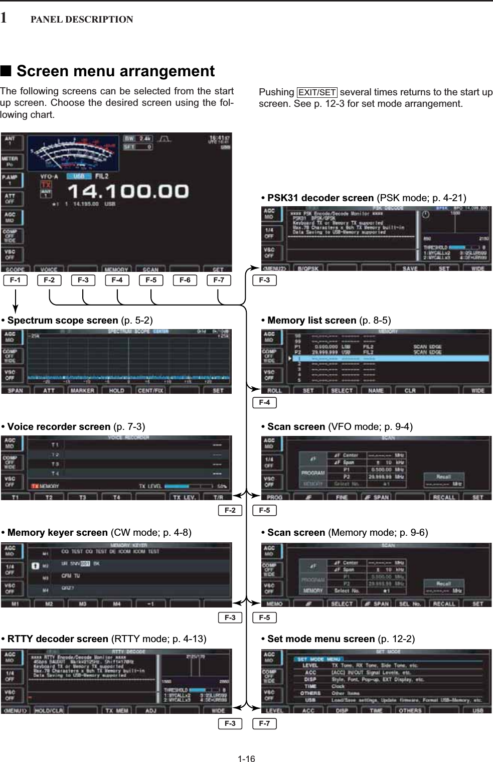
![1-7MF5 (MULTI-FUNCTION 5 SWITCH)➥Activates and selects fast, mid-rangeor slow AGC time constant whenpushed. (p. 5-11)• In FM mode, only “FAST” is available.➥Enters the AGC set mode whenpushed and held for 1 sec. (p. 5-11)AGC time constant can be set between0.1 to 8.0 sec. (depends on mode), orturned OFF. When AGC is “OFF,” theS-meter does not function.✔What is the AGC?The AGC controls receiver gain to produce a constantaudio output level, even when the received signalstrength varies dramatically. Select “FAST” for tuning andthen select “MID” or “SLOW” depending on the receivingcondition.MF6 (MULTI-FUNCTION 6 SWITCH)➥Turns the speech compressor ON andOFF in SSB mode. (p. 6-5)➥Switches the narrow, middle or widecompression when pushed and heldfor 1 sec.✔What is the speech compressor?The speech compressor compresses the transmitteraudio input to increase the average audio output level, toincrease talk power. This function is effective for long-dis-tance communication or when propagation conditions arepoor.➥Turns the 1⁄4-speed tuning function ONand OFF in SSB data, CW, RTTY andPSK modes. (p. 3-6)•1⁄4function sets dial rotation to 1⁄4of nor-mal speed for fine tuning.➥Switches between the tone encoder,tone squelch function and no-tone op-eration when pushed in FM mode. (pgs. 4-33, 4-34)➥Enters the tone set mode whenpushed and held for 1 sec. in FMmode. (pgs. 4-33, 4-34)MF7 (MULTI-FUNCTION 7 SWITCH)➥Switches the voice squelch controlfunction ON and OFF; useful for scan-ning. (p. 9-3)#4 LCD FUNCTION SWITCHES – Push to select the function indicated in the LCD dis-play above these switches.• Functions vary depending on the operating condition.#5 TRANSMIT INDICATOR [TX]Lights red while transmitting.#6 RECEIVE INDICATOR [RX]Lights green while receiving a signal and when thesquelch is open.#7 LCD FUNCTION DISPLAY (p. 1-14)Shows the operating frequency, function switchmenus, spectrum scope screen, memory listscreen, set mode settings, etc.#8 SPLIT OPERATION INDICATOR [SPLIT]Lights during split frequency operation.#9 LOCK INDICATOR [LOCK] (p. 5-17)Lights when the dial lock function is activated.$0 TRANSMIT FREQUENCY CHECK SWITCH[XFC] (p. 6-6)Monitors the transmit frequency (including ∂TX fre-quency offset) when pushed and held during split fre-quency operation.• While pushing this switch, the transmit frequency can bechanged with the main dial, keypad, memo pad or / switches.• When the split lock function is turned ON, pushing [XFC]cancels the dial lock function. (p. 6-7)$1 MEMORY UP/DOWN SWITCHES / (p. 8-2)Push to select the desired memory channel.• Memory channels can be selected both in VFO andmemory modes.$2 KEYPAD➥Pushing a key selects the operating band. (p. 3-4)• selects the general coverage band.➥Pushing the same key 2 or 3 times calls up otherstacked frequencies in the band. (p. 3-4)• Icom’s triple band stacking register memorizes 3 fre-quencies in each band.➥After pushing , enters a frequency ormemory channel. Pushing or /is necessary to end the entry. (pgs. 3-5, 8-2)• e.g. to enter 14.195 MHz, push .F-INPENT14 528 91.8 1GENE •10 41.8 1F-INPENT√∫F-INPENTF-INPENTGENE •√∫√∫F-7F-1VSCOFFTONEOFF1/4ONCOMPOFFWIDEAGCMID1PANEL DESCRIPTION](https://usermanual.wiki/ICOM-orporated/300900.User-Manual-Part-1/User-Guide-900712-Page-18.png)
![1-8$3 MODE SWITCHESSelects the desired mode. (p. 3-8)• Announces selected mode via the speech synthesizer.(p. 12-15)Selects USB and LSB modes alter-nately.Selects CW and CW-R (CW reverse)modes alternately.➥Switches between RTTY and PSKmode.➥Switches RTTY and RTTY-R (RTTYreverse) mode when pushed and heldfor 1 sec. in RTTY mode.➥Switches PSK and PSK-R (PSK re-verse) mode when pushed and heldfor 1 sec. in PSK mode.Selects AM and FM modes alternately.➥Selects SSB, AM or FM data mode(USB-D, LSB-D, AM-D, FM-D) whenpushed in SSB, AM or FM mode, re-spectively.➥Switches D1, D2 and D3 whenpushed and held for 1 sec. $4 QUICK TUNING SWITCH [TS]➥Turns the quick tuning step ON and OFF. (p. 3-6)• While the quick tuning indicator, “Z,” is displayedabove the frequency indication, the frequency can bechanged in programmed kHz steps.• 0.1, 1, 5, 9, 10, 12.5, 20 and 25 kHz steps are avail-able for each operating mode independently.➥When the quick tuning step is OFF, push andhold for 1 sec. to turn the 1 Hz tuning step ONand OFF. (p. 3-7)➥When the quick tuning step is ON, push and holdfor 1 sec. to enter quick tuning step set mode.(p. 3-6)$5 VFO SELECT SWITCH Switches the selected VFO between the VFO-A andVFO-B when pushed.• Switches between transmit frequency and receive fre-quency when the split frequency function is ON. (p. 6-6)$6 MEMORY WRITE SWITCH (p. 8-3)Stores the selected readout frequency and operat-ing mode into the displayed memory channel whenpushed and held for 1 sec.• This function is available both in VFO and memorymodes.MWA/BDATAAM/FMRTTY/PSKCWSSB1PANEL DESCRIPTIONSSB CWRTTY/PSKAM/FM DATA AUTOTUNELOCKTSXFCM.SCOPEEXIT/SETRECPLAYVOICE MEMORYBRIGHTCONTRASTVOX GAINMONI GAINCOMPDRIVE ANTI VOXMONITORRFDIGI-SEL NOTCHRIT/∂TXCW PITCHTWIN-PBTDDELAYF-1 F-2 F-3 F-4 F-5 F-6 F-7LOCKTX RX SPLITFILTERPBT-CLRDIGI-SELAPF/TPFNOTCHRITCLEARSPEECH11.823.537410514618721824MP-W MP-RMW V/MA/B A=B928GENE050ENTF-INP∂TXNBSPLIT7700NSCEIVERNB$5 $7 $8 $9 %0 %2$6%8 %9%7 ^0$4 %1%4 %5$3%6%3■Front panel (continued)](https://usermanual.wiki/ICOM-orporated/300900.User-Manual-Part-1/User-Guide-900712-Page-19.png)
![1-9$7 MEMO PAD-WRITE SWITCH (p. 8-7)Programs the displayed readout frequency and op-erating mode into a memo pad.• The 5 most recent entries remain in memo pads.• The memo pad capacity can be expanded from 5 to 10in set mode. (p. 12-15)$8 MEMO PAD-READ SWITCH (p. 8-7)Each push calls up a frequency and operating modein a memo pad. The 5 (or 10) most recently pro-grammed frequencies and operating modes can berecalled, starting from the most recent.• The memo pad capacity can be expanded from 5 to 10in set mode. (p. 12-15)$9 VFO/MEMORY SWITCH ➥Switches the selected readout operating modebetween the VFO and memory when pushed.(pgs. 3-3, 8-2)➥Transfers the memory contents to VFO whenpushed and held for 1 sec. (p. 8-4)%0 VFO EQUALIZING SWITCH (p. 3-3)Transfers the undisplayed VFO frequency to thedisplayed VFO frequency when pushed and held for1 sec.%1 FILTER SWITCH (p. 5-13)➥Selects one of 3 IF filter settings.➥Enters the filter set screen when pushed andheld for 1 sec.%2 AUDIO PEAK FILTER/TWIN PEAK FILTERSWITCH➥Push to turn the audio peak filter ON and OFFduring CW mode operation. (p. 4-6)• “ ” appears when audio peak filter is in use.➥Push to turn the twin peak filter ON and OFF dur-ing RTTY mode operation. (p. 4-14)• “ ” appears when twin peak filter is in use.➥During CW mode operation, push and hold for1 sec. to select the APF passband width from320, 160 and 80 Hz. (p. 4-6)%3 MINI SPECTRUM SCOPE SWITCH (p. 5-4)➥Turns the mini spectrum scope screen ON andOFF when pushed.• The mini spectrum scope screen can be displayedwith another screen, such as memory or set modescreen, simultaneously.➥Turns the spectrum scope screen ON whenpushed and held for 1 sec.%4 VOICE MEMORY RECORD SWITCH (p. 7-3)➥Push to record the received signal for the presettime period.• After the preset time has passed, stops recording au-tomatically.➥Push and hold for 1 sec. to record the receivedsignal until the recording is canceled. • Push this switch momentarily to stop recording.• The memory records the latest 30 sec. of audio.%5 VOICE MEMORY PLAYBACK SWITCH (p. 7-4)➥Plays back the previously recorded audio for thepreset time period when pushed.➥Plays back all of the previously recorded audiowhen pushed and held for 1 sec.%6 EXIT/SET SWITCH ➥Push to exit, or return to the previous screen in-dication during spectrum scope, memory, scan orset mode screen display.➥Displays set mode menu screen when pushedand held for 1 sec.%7 MAIN DIALChanges the displayed frequency, selects set modesetting, etc.%8 LOCK SWITCH [LOCK] (p. 5-17)Push to switch the dial lock function ON and OFF. %9 SPEECH SWITCH (p. 3-11)➥Push to announce the S-meter indication and theselected frequency.➥The selected operating mode is additionally an-nounced when pushed and held for 1 sec.^0 SPLIT SWITCH (p. 6-6)➥Turns the split function ON and OFF whenpushed.➥Turns the split function ON. When pushed andheld for 1 sec. in non-FM modes, transfers theunselected VFO’s readout frequency to the se-lected VFO’s readout and sets the unselectedVFO to transmit VFO. (Quick split function)• The offset frequency is shifted from the selected VFOfrequency in FM mode. (p. 12-13)• The quick split function can be turned OFF using setmode. (p. 12-12)➥Turns the split function ON and shifts the unse-lected VFO frequency after inputting an offset.SPLITSPEECHEXIT/SETPLAYRECM.SCOPETPFAPFAPF/TPFFILTERA=BV/MMP-RMP-W1PANEL DESCRIPTION](https://usermanual.wiki/ICOM-orporated/300900.User-Manual-Part-1/User-Guide-900712-Page-20.png)
![1-10^1 PASSBAND TUNING CONTROLS [TWIN-PBT] (p. 5-12)Adjusts the receiver’s IF filter “passband width” viathe DSP. • Passband width and shift frequency are displayed in themulti-function display.• Push and hold for 1 sec. to clear the PBTsettings.• Adjustment range is set to half of the IF filter passbandwidth. 25 Hz steps and 100 Hz steps are available.✔What is the PBT control?The PBT function electronically modifies the IF passbandwidth to reject interference. This transceiver uses theDSP circuit for the PBT function.^2 PBT CLEAR SWITCH (p. 5-12)Clears the PBT settings when pushed and held for1 sec.• The [PBT-CLR] indicator above this switch lights whenPBT is in use.^3 DIGITAL RF SELECTOR SWITCH (p. 5-18)Turns the digital RF preselector ON and OFF.• The [DIGI-SEL] indicator lights green when the prese-lector is in use.^4 DIGITAL RF SELECTOR CONTROL [DIGI-SEL](p. 5-18)Adjusts the digital RF selector center frequency.• The control can be reassigned as the audio peak filteradjustment (p. 12-16)DIGI-SELPBT-CLRPBT-CLRHigherfrequencyLowerfrequencyPBT1PBT2Low cutHigh cut Center–+1PANEL DESCRIPTIONSSB CWRTTY/PSKAM/FM DATA AUTOTUNELOCKTSXFCM.SCOPEEXIT/SETRECPLAYVOICE MEMORYBRIGHTCONTRASTVOX GAINMONI GAINCOMPDRIVE ANTI VOXDIGI-SEL NOTCHRIT/∂TXCW PITCHTWIN-PBTF-1 F-2 F-3 F-4 F-5 F-6 F-7LOCKTX RX SPLITFILTERPBT-CLRDIGI-SELAPF/TPFNOTCHRITCLEARSPEECH11.823.537410514618721824MP-W MP-RMW V/MA/B A=B928GENE050ENTF-INP∂TXSPLIT&1 &0 ^9^1^2^3^4^5^6^7^8■Front panel (continued)](https://usermanual.wiki/ICOM-orporated/300900.User-Manual-Part-1/User-Guide-900712-Page-21.png)
Varies the “valley” frequency of the manual notch fil-ter to reject an interfering signal while the manualnotch function is ON.• Notch filter center frequency:SSB : –1060 Hz to 4040 HzCW : CW pitch freq. + 2540 Hz to CW pitch freq.–2540 Hz AM : –5100 Hz to 5100 Hz^6 NOTCH SWITCH (p. 5-18)➥Switches the notch function between auto, man-ual and OFF in SSB and AM modes.➥Turns the manual notch function ON and OFFwhen pushed in CW, RTTY and PSK31 mode.➥Turns the auto notch function ON and OFF whenpushed in FM mode.• “ ” appears when manual notch is in use.• “ ” appears when auto notch is in use.➥Switches the manual notch characteristics fromwide, middle and narrow when pushed and heldfor 1 sec. ✔What is the notch function?The notch function is a narrow filter that eliminates un-wanted CW or AM carrier tones while preserving the de-sired voice signal. The DSP circuit automatically adjuststhe filtering frequency to effectively eliminate unwantedtones.^7 RIT/∂TX CONTROL [RIT/∂TX] (pgs. 5-10, 6-4)Shifts the receive and/or transmit frequency withoutchanging the transmit and/or receive frequencyshown on the main VFO.• Rotate the control clockwise to increase the frequency,or rotate the control counterclockwise to decrease thefrequency. The RIT or ∂TX functions must be ON.• The shift frequency range is ±9.999 kHz in 1 Hz steps(or ±9.99 kHz in 10 Hz steps).^8 CW PITCH CONTROL [CW PITCH] (p. 4-5)Shifts the received CW audio pitch and the CW sidetone pitch without changing the operating frequency.^9 RIT SWITCH (p. 5-10)➥Turns the RIT function ON and OFF whenpushed.• Use [RIT/∂TX] control to vary the RIT frequency.➥Adds the RIT shift frequency to the operating fre-quency when pushed and held for 1 sec.✔What is the RIT function?Receiver incremental tuning (RIT) shifts the receive fre-quency without shifting the transmit frequency.This is useful for fine tuning stations calling you off-fre-quency or when you prefer to listen to slightly different-sounding voice characteristics, etc.&0 CLEAR SWITCH (pgs. 5-10, 6-4)Clears the RIT/∂TX shift frequency when pushedand held for 1 sec. or when pushed momentarily,depending on the quick RIT/∂TX clear function set-ting (p. 12-15).&1∂TX SWITCH (p. 6-4)➥Turns the ∂TX function ON and OFF whenpushed.• Use [RIT/∂TX] control to vary the ∂TX frequency.➥Adds the ∂TX shift frequency to the operatingfrequency when pushed and held for 1 sec.✔What is the ∂TX function?∂TX shifts the transmit frequency without shifting the re-ceive frequency. This is useful for simple split frequencyoperation in CW, etc.∂TXCLEARRITANMNNOTCHHighfrequencyLowfrequencyFrequencyincreasesFrequencydecreasesHigherfrequencyLowerfrequency1PANEL DESCRIPTION](https://usermanual.wiki/ICOM-orporated/300900.User-Manual-Part-1/User-Guide-900712-Page-22.png)
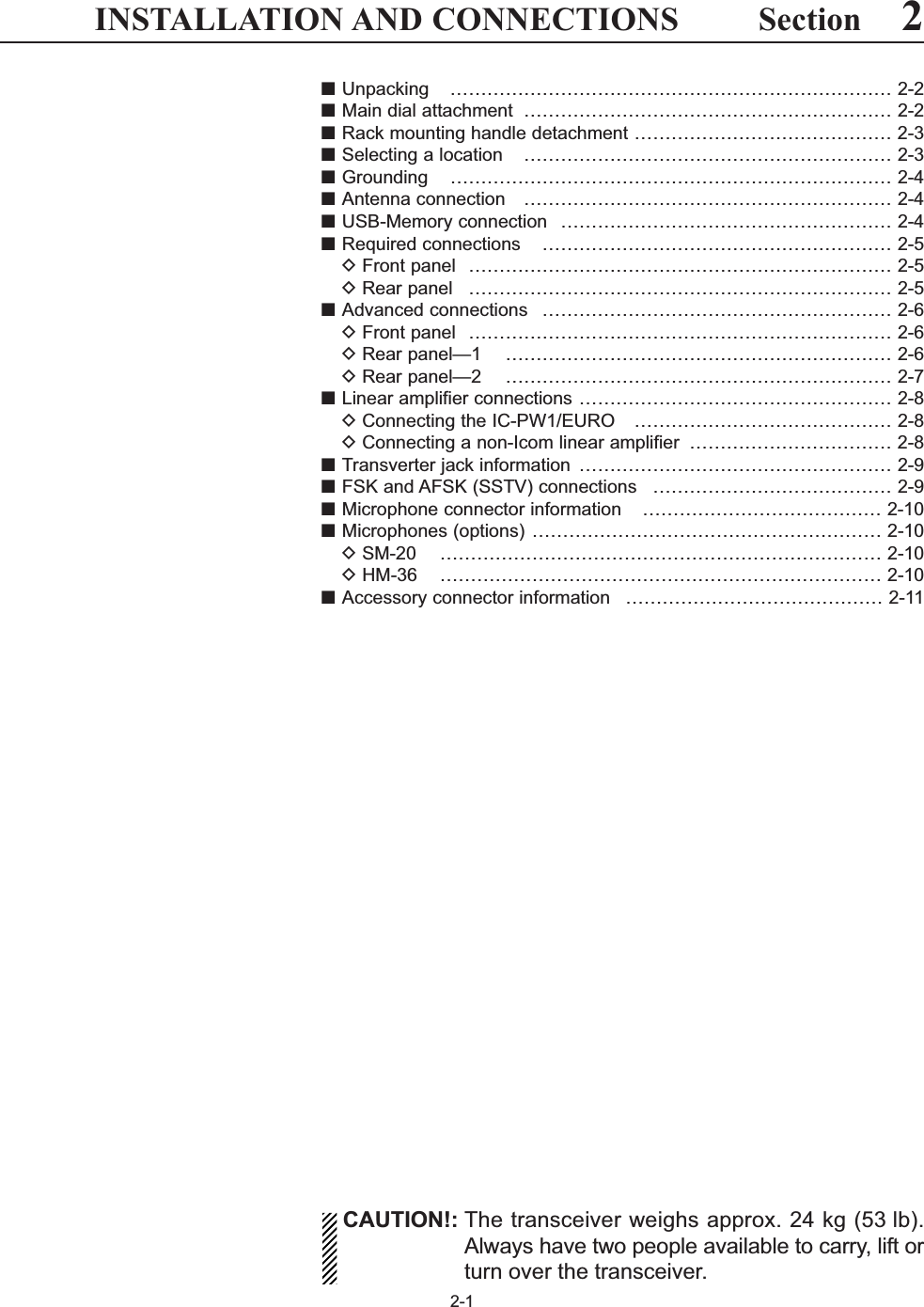
![qANTENNA CONNECTOR 1 [ANT 1] (p. 2-5)wANTENNA CONNECTOR 2 [ANT 2] (p. 2-5)eANTENNA CONNECTOR 3 [ANT 3] (p. 2-5)rANTENNA CONNECTOR 4 [ANT 4] (p. 2-5)Accept a 50 antenna with a PL-259 plug connec-tor.tGROUND TERMINAL [GND] (p. 2-4)Connect this terminal to a ground to prevent electri-cal shocks, TVI, BCI and other problems.yCIRCUIT BREAKERCuts off the AC input when over-current occurs.uEXTERNAL DISPLAY TERMINAL[EXT-DISPLAY] (p. 2-7)Connects to an external display monitor.• At least 800×600 pixel display is necessary.iETHERNET CONNECTOR (p. 16-6)Connects to a PC through a LAN (Local Area Net-work).oCI-V REMOTE CONTROL JACK [REMOTE] (pgs. 2-6, 14-2)➥Connects a PC via the optional CT-17 CI-V LEVELCONVERTER for external control of the transceiver.➥Used for transceive operation with another IcomCI-V transceiver or receiver.!0 RS-232C TERMINAL [RS-232C] (p. 2-6)Connects an RS-232C cable, D-sub 9-pin to con-nect the IC-7700 to a PC. Can be used to remotely control the IC-7700 with-out the optional CT-17, or for RTTY/PSK31 de-coded signal output. The [RS-232C] interface iswired as a modem (DCE).!1 MAIN POWER SWITCH [I/O] (p. 3-2)Turns the internal power supply ON and OFF.!2 AC POWER SOCKET [AC] (p. 2-5)Connects the supplied AC power cable to an ACline-voltage receptacle.!3 REFERENCE SIGNAL INPUT/OUTPUT TERMINAL [REF I/O]Inputs/outputs a 10 MHz reference signal.!4 STRAIGHT KEY JACK [CW KEY] (p. 2-5)Accepts a straight key or external electronic keyerwith 1⁄4inch standard plug.• [ELEC-KEY] on the front panel can be used for astraight key or external electronic keyer. Deactivate theinternal electronic keyer in keyer set mode. (p. 4-12)1-121PANEL DESCRIPTIONALCADJALCRELAY CW KEYEXTKEYPADMETERDC OUT15VMAX1AREF I/O10MHz-10dBmINOUTREMOTE RS-232CEXT-DISPLAYRX ANTINOUTS/P DIF12ACCEXT-SPANT 1 ANT 2 ANT 3 ANT 4GNDAC15AIX-VERTERu i o !0!4 !3!5!6!7!8!9@0@1@2@3@4@5@6@7@8!1!2t yqwer■Rear panel(+)(_)](https://usermanual.wiki/ICOM-orporated/300900.User-Manual-Part-1/User-Guide-900712-Page-23.png)
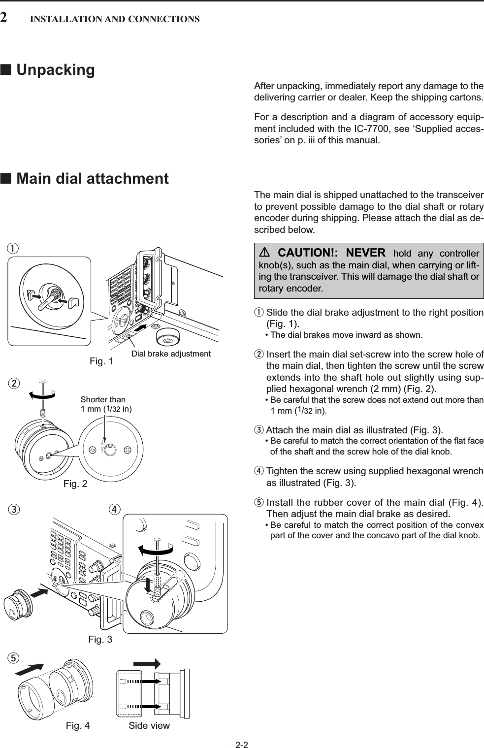
![1-13!5 S/P DIF INPUT TERMINAL [S/P DIF– IN] (p. 2-7)!6 S/P DIF OUTPUT TERMINAL [S/P DIF– OUT] (p. 2-7)Connects external equipment that supports S/P DIFinput/output.!7 ALC LEVEL ADJUSTMENT POT [ALC ADJ] Adjusts the ALC levels.No adjustment is required when the ALC outputlevel of a connected non-Icom linear amplifier is 0to –4 V a DC.!8 ALC INPUT JACK [ALC] (p. 2-8)Connects to the ALC output jack of a non-Icom lin-ear amplifier.!9 T/R CONTROL JACK [RELAY] (p. 2-8)Connects to ground when transmitting to control anexternal unit, such as a non-Icom linear amplifier.@0 ACCESSORY SOCKET 1 [ACC 1] @1 ACCESSORY SOCKET 2 [ACC 2] Enable connection of external equipment such as alinear amplifier, an automatic antenna selector/tuner, a TNC for data communications, etc.• See p. 2-11 for socket information.@2EXTERNAL SPEAKER JACK [EXT-SP](p. 2-6)Connects an external speaker (4–8 ), if desired.@3 EXTERNAL KEYPAD JACK [EXT KEYPAD] (p. 2-7)Connects an external keypad for direct voice mem-ory or electronic keyer control.Transceiver mute control line (both transmit and re-ceive) is also supported.@4 METER JACK [METER] (p. 2-7)Outputs a signal showing received signal strength,transmit output power, VSWR, ALC, speech com-pression, VDor IDlevel for external meter indication.@5 DC OUTPUT JACK [DC OUT] (p. 2-7)Outputs a regulated 14 V DC (approx.) for externalequipment. Connected in parallel with 13.8 V out-puts of [ACC 1] and [ACC 2]. (max. 1 A in total)@6 TRANSVERTER CONNECTOR [X-VERTER] (p. 2-6)External transverter input/output connector.Activated by voltage applied to [ACC 2] pin 6, orwhen the transverter function is in use. (pgs. 2-11)@7 RECEIVE ANTENNA IN [RX ANT– IN]@8 RECEIVE ANTENNA OUT [RX ANT– OUT]Located between the transmit/receive switching cir-cuit and receiver’s RF stage.Connects an external unit, such as preamplifier orRF filter, using BNC connectors, if desired.When no external unit is connected, [RX ANT– IN]and [RX ANT– OUT] must be deactivated andshorted by the switching relay internally. This set-ting is available on the antenna set screen. (p. 10-5)NOTE: T/R control voltage and current must belower than 16 V DC/0.5 A (or 250 V AC,200 mA with MOSFET switching).1PANEL DESCRIPTIONReceiverTransmitterIN[RX ANT]OUTTransmit/Receiveswitching circuitANTRXonly+__](https://usermanual.wiki/ICOM-orporated/300900.User-Manual-Part-1/User-Guide-900712-Page-24.png)
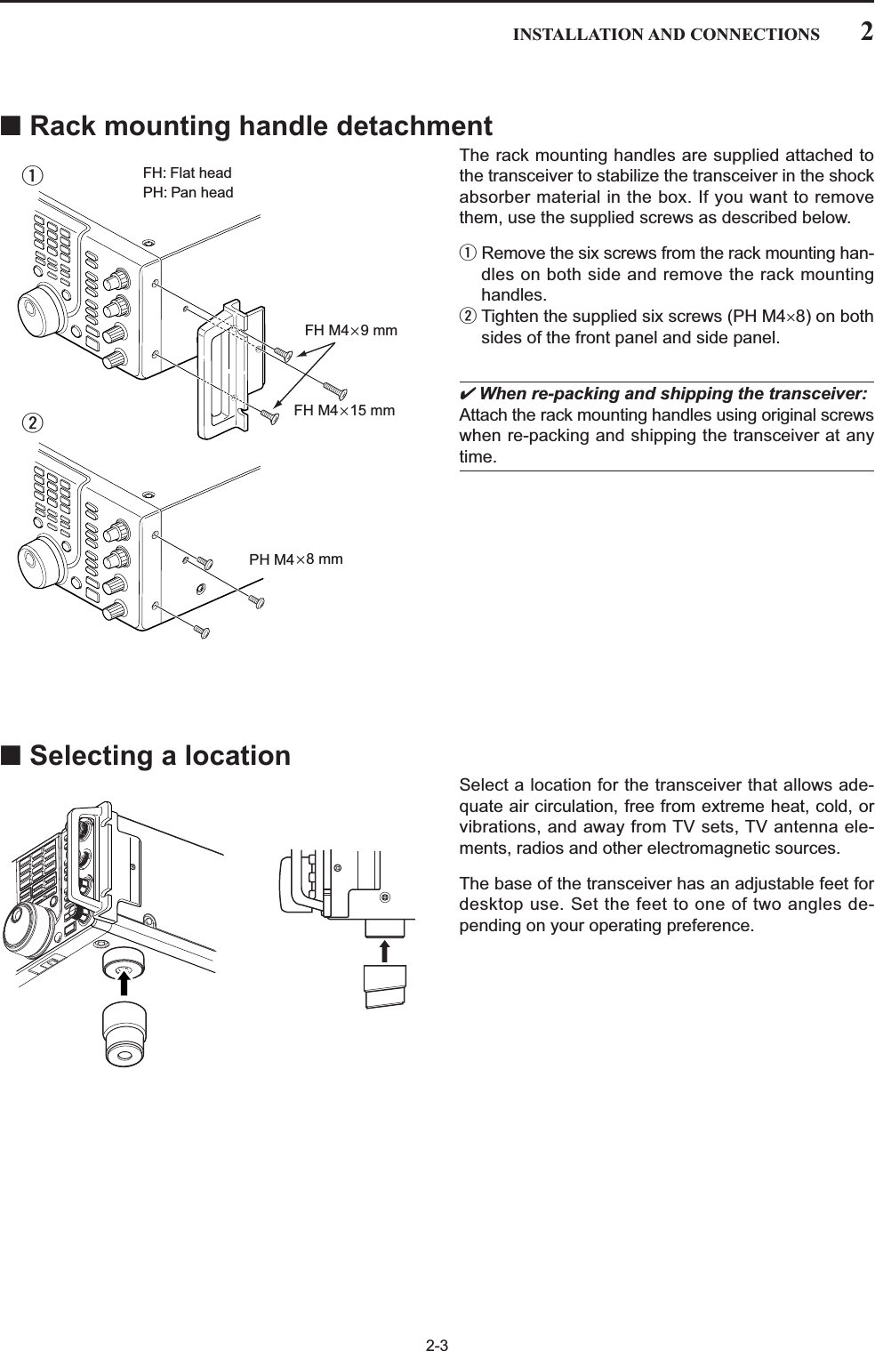
![2-42INSTALLATION AND CONNECTIONS■GroundingTo prevent electrical shock, television interference(TVI), broadcast interference (BCI) and other prob-lems, ground the transceiver through the GROUNDterminal on the rear panel.For best results, connect a heavy gauge wire or strapto a long earth-sunk copper rod. Make the distance be-tween the [GND] terminal and ground as short as pos-sible.RWARNING: NEVER connect the [GND]terminal to a gas or electric pipe, since the connec-tion could cause an explosion or electric shock.■Antenna connectionFor radio communications, the antenna is of critical im-portance, along with output power and receiver sensi-tivity. Select antenna(s), such as a well-matched 50 antenna, and feedline. We recommend 1.5:1 or betterof Voltage Standing Wave Ratio (VSWR) for your de-sired band. Of course, the transmission line should bea coaxial cable.When using 1 antenna, use the [ANT1] connector.CAUTION: Protect your transceiver from lightningby using a lightning arrestor.■USB-Memory connection (USB-Memory: Not supplied by Icom)Connect the USB-Memory* to the USB connector. • Unmount operation is necessary before removing the USB-Memory* (p.12-25).Make sure to connect the USB-Memory correctly. NEVER connect or remove the USB-Memory whenthe read/write indicator lights or blinks.A USB keyboard* or USB hub* can also be con-nected to the USB connector.*: USB-Memory, USB keyboard or USB hub is not suppliedby Icom.Antenna SWREach antenna is tuned for a specified frequencyrange and SWR may be increased out-of-range.When the SWR is higher than approx. 2.0:1, thetransceiver’s power drops to protect the final transis-tors. In this case, an antenna tuner is useful to matchthe transceiver and antenna. Low SWR allows fullpower for transmitting. The IC-7700 has an SWRmeter to monitor the antenna SWR continuously.PL-259 CONNECTOR INSTALLATION EXAMPLE30 mm §9⁄8in 10 mm §3⁄8in 1–2 mm §1⁄16 in30 mm10 mm (soft solder)10 mm1–2 mmsolder solderSoftsolderCoupling ringSlide the coupling ring down. Strip the cable jacket and in the braid.Slide the connector body on and solder it.Screw the coupling ring onto the connector body.Strip the cable as shown at left. Tin the center conductor.qweror](https://usermanual.wiki/ICOM-orporated/300900.User-Manual-Part-1/User-Guide-900712-Page-31.png)
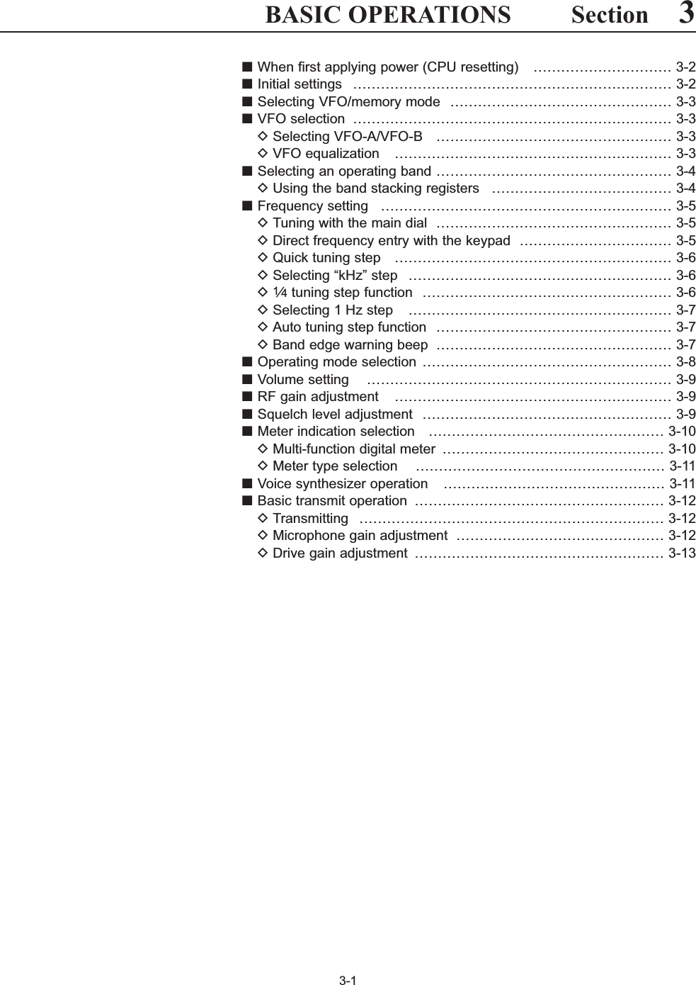
![2-52INSTALLATION AND CONNECTIONS■Required connectionsDFront panelPOWERTUNERTIMERVOXSSB CWRTTY/PSVOX GAINMONI GAINCOMPDRIVEBK-IN MONITORTRANSMITMICELEC-KEYPHONESAF RFMIC RF PWRKEY SPEEDDELAYF-1 F-2 F-3TX RXAGC VRNR NBi7700HF/50MHz TRANSCEIVERAGC SQL NR NBMicrophones (p. 2-10)CW keyA straight or bug key can be used when the internal electronic keyer is turned OFF in keyer set mode. (p. 4-12)OptionalSM-20OptionalHM-36DRear panelALCADJALCRELAY CW KEYEXTKEYPADMETERDC OUT15VMAX1AREF I/O10MHz-10dBmINOU TREMOTE RS-232CEXT-DISPLAYRX ANTINOUTS/P DIF12ACCEXT-SPANT 1 ANT 2 ANT 3 ANT 4GNDAC15AIX-VERTERAntenna 1, 2, 3, 4 (p. 2-4) Straight keyGround(p. 2-4)Use the heaviest gauge wire or strap available and make the connection as short as possible.Grounding prevents elec-trical shocks, TVI and other problems.AC outletR WARNING:Use the supplied AC power cable only.NOTE: Attach the sup-plied antenna connec-tor cap when no anten-na or external equip-ment is connected.[Example]: ANT1 for 1.8–18 MHz bands, ANT 2 for 21–28 MHz bandsANT3 for 50 MHz band, ANT 4 for receive antenna.](https://usermanual.wiki/ICOM-orporated/300900.User-Manual-Part-1/User-Guide-900712-Page-32.png)
![2-62INSTALLATION AND CONNECTIONS■Advanced connectionsDFront panelALCADJALCRELAY CW KEYEXTKEYPADMETERDC OUT15VMAX1AREF I/O10MHz-10dBmINOU TREMOTE RS-232CEXT-DISPLAYRX ANTINOUTS/P DIF12ACCEXT-SPANT 1 ANT 2 ANT 3 ANT 4GNDAC15AIX-VERTERRX ANT IN/OUTConnects an external preamp or lowpass filter.RX ANT IN/OUT must be activated in the antenna set screen (p.10-5).ACC sockets(pgs. 2-9, 2-11)Antenna 1, 2, 3, 4 (p. 2-8)Connects a linear amplifier, antenna selector, etc.[X-VERTER]Connects a transverter for V/UHF band use.[RELAY], [ALC] (p. 2-8)Used for connecting a non-Icom linear amplifier.External speaker (p. 15-4)SP-20(option)[REMOTE], [RS-232C] (p. 14-2)Used for computer control and transceive operation. The optional CT-17 is required when connecting a PC to [REMOTE].POWERTUNERTIMERVOXSSB CWRTTY/PSKVOX GAINMONI GAINCOMPDRIVEBK-IN MONITORTRANSMITMICELEC-KEYPHONESAF RFMIC RF PWRKEY SPEEDDELAYF-1 F-2 F-3TX RXAGC VRNR NBi7700HF/50MHz TRANSCEIVERAGC SQL NR NBMICHeadphonesUSB-MemoryThe AFSK modulation signal can also be input to [MIC].KeyboardConnects an USB type PC key-board directly for RTTY/PSK31 op-eration, as well as other text edit op-erations.DRear panel— 1](https://usermanual.wiki/ICOM-orporated/300900.User-Manual-Part-1/User-Guide-900712-Page-33.png)
![2-72INSTALLATION AND CONNECTIONSDRear panel— 2ALCADJALCRELAY CW KEYEXTKEYPADMETERDC OUT15VMAX1AREF I/O10MHz-10dBmINOU TREMOTE RS-232CEXT-DISPLAYRX ANTINOUTS/P DIF12ACCEXT-SPANT 1 ANT 2 ANT 3 ANT 4GNDAC15AIX-VERTERExternal DisplayConnects a PC-style monitor display (at least 800×600 resolution).Video output signal can be turned ON and OFF in set mode (p. 12-11) [DC OUT]Outputs regulated 14 V (approx.) DC for external equipment power supply. (max. 1 A capacity)External keypadConnects an external keypad for direct voice memory and memory keyer controls.Connects a PC for audio signal data (48 kHz, 16-bit) input/output.[S/P DIF IN/OUT]Connects a PC via a LAN for the CPU firmware update.Ethernet connector (p. 16-6)1.5 kΩ±5%1.5 kΩ±5%2.2 kΩ±5%4.7 kΩ±5%S1(T1/M1)S2(T2/M2)S3(T3/M3)S4(T4/M4)EXTERNAL KEYPAD3.5 (d) mm; 1⁄8″ plugMute switch: Mutes both transmission and reception when switched ON during trans-ceive operation, etc.[METER]Connects an external meter, etc.3.5 (d) mm; 1⁄8″ plug](https://usermanual.wiki/ICOM-orporated/300900.User-Manual-Part-1/User-Guide-900712-Page-34.png)
![DConnecting a non-Icom linear amplifier RWARNING:Set the transceiver output power and linear ampli-fier ALC output level after referring to the linear am-plifier instruction manual.The ALC input level must be in the range 0 V to–4 V. The transceiver does not accept positive volt-age. Non-matched ALC and RF power settingscould overheat or damage the linear amplifier.The maximum signal level of [RELAY] jack is16 V/0.5 A DC with initial setting, and 250 V/200 mAwith “MOSFET” setting (see p. 12-8 for details). Usean external relay unit if your non-Icom linear ampli-fier requires control voltage and/or current greaterthan specified.■Linear amplifier connectionsDConnecting the IC-PW1/EURO2-82INSTALLATION AND CONNECTIONSRF OUTPUT RF INPUTSENDALC50 1coaxial cableTransceiverANT1ALCRELAYTo an antennaNon-Icom linear amplifierTo anantennaACC-1ANTANT2ANT1ACC 2INPUT1INPUT2REMOTEEXCITER11&2GNDGNDIC-PW1/EUROAC outlet(Non-European versions: 100–120/220–240 V European version : 230 V)GroundTransceiverREMOTERemote control cable (supplied with the IC-PW1/EURO)ACC cable (supplied with the IC-PW1/EURO)Be sure to connect the cableto the 7-pin ACC 2 jack.Coaxial cable(supplied with the IC-PW1/EURO)Coaxial cable**OptionalConnect[INPUT2]if necessary](https://usermanual.wiki/ICOM-orporated/300900.User-Manual-Part-1/User-Guide-900712-Page-35.png)
![2-92INSTALLATION AND CONNECTIONS■Transverter jack informationWhen 2 to 13.8 V is applied to pin 6 of [ACC 2], the [X-VERTER] connector is activated for transverter oper-ation and the antenna connectors do not receive ortransmit any signals.While receiving, [X-VERTER] connector can be acti-vated as an input terminal from an external transverter.While transmitting, the [X-VERTER] connector outputssignals of the displayed frequency at –20 dBm (22 mV)as signals for the external transverter.■FSK and AFSK (SSTV) connectionsTo connect a TNC or scan converter, etc., refer to thediagram below.Connect to serial port, parallel port, speaker jack, microphone jack and line IN/OUT jack, etc.See the instruction manual of the application for details.D AFSK operation• When connecting to [ACC 1]• When connecting to [MIC]• When using a PC application• When using a TNCPCRS-232CTNC or scan converterPTTAudio outputAF inputGNDAFSK outputAF inputGNDPTT*SQL input†*When using the VOX function, no need to connect. Refer to the instruction manual of the external equipment (TNC, etc.).†When connecting the squelch line, consult the necessary manual (TNC, etc.).qwertyui12345678zzxxccvv*zxcvzxcvbbn†n†bn†Rear panel viewRear panel viewPCRS-232CTNC or scan converterConnect to serial port, parallel port, speaker jack, microphone jack and line IN/OUT jack, etc.See the instruction manual of the application for details.DFSK operation— when connecting to [ACC 1]• When using a PC application• When using a TNC12345678Rear panel viewRear panel viewRTTYGNDAFSENDRTTYGNDAFSENDRTTY OUTPUTGNDAUDIO INPUTPTTRTTY OUTPUTGNDAUDIO INPUTPTT12345678Transverter connector](https://usermanual.wiki/ICOM-orporated/300900.User-Manual-Part-1/User-Guide-900712-Page-36.png)
![■Microphone connector information(Front panel view)CAUTION: DO NOT short pin 2 to ground as thiscan damage the internal 8 V regulator.NOTE: DC voltage is applied to pin 1 for micro-phone operation. Use caution when using a non-Icom microphone.■Microphones (options)qUP/DOWN SWITCHES [UP]/[DN]Change the selected readout frequency or memorychannel.• Continuous pushing changes the frequency or memorychannel number continuously.• While pushing [XFC], the transmit readout frequency canbe controlled while in split frequency operation.• The [UP]/[DN] switch can simulate a key paddle. Presetin the keyer set mode. (p. 4-12)wPTT SWITCHPush and hold to transmit; release to receive.ePTT LOCK SWITCH (available for SM-20 only)Push to toggle between transmit and receive.2-102INSTALLATION AND CONNECTIONS[MIC] FUNCTION DESCRIPTIONPin No.w+8 V DC output Max. 10 mAeFrequency up GroundFrequency down Ground through 470 rSquelch open “Low” levelSquelch closed “High” levely GND (PTT ground)t PTTr Squelch switchq Microphone inputw +8 V DC outpute Frequency up/downu GND (Microphone ground)i AF output (varies with [AF])D SM-20D HM-36qwqwe](https://usermanual.wiki/ICOM-orporated/300900.User-Manual-Part-1/User-Guide-900712-Page-37.png)
![2-112INSTALLATION AND CONNECTIONS■Accessory connector informationACC 2PIN No.NAME DESCRIPTION SPECIFICATIONSACC 1PIN No.NAME DESCRIPTION SPECIFICATIONSNOTE: If the CW side tone level limit or beep levellimit is in use, the CW side tone or beep tone de-creases from the fixed level when the [AF] control isrotated above a specified level. (p. 12-6)12345678“High” level : More than 2.4 V1 RTTY Controls RTTY keying “Low” level : Less than 0.6 VOutput current : Less than 2 mA2 GND Connects to ground. Connected in parallel with ACC 2 pin 2.Input/output pin. Ground level : –0.5 V to 0.8 V3 SEND Goes to ground when transmitting. Output current : Less than 20 mAWhen grounded, transmits. Input current (Tx) : Less than 200 mAConnected in parallel with ACC 2 pin 3.4 MOD Modulator input. Input impedance : 10 kConnects to a modulator. Input level : Approx. 100 mV rmsAF detector output. Output impedance : 4.7 k5 AF Fixed, regardless of [AF] position Output level : 100–300 mV rmsin default settings. (see notes below)6 SQLS Squelch output. SQL open : Less than 0.3 V/5 mAGoes to ground when squelch opens.SQL closed : More than 6.0 V/100 μA7 13.8 V 13.8 V output when power is ON. Output current : Max. 1 AConnected in parallel with ACC 2 pin 7.Control voltage : –4 V to 0 V8 ALC ALC voltage input. Input impedance : More than 10 kConnected in parallel with ACC 2 pin 5.1 8 V Regulated 8 V output. Output voltage : 8 V ±0.3 VOutput current : Less than 10 mA2 GND Same as ACC 1 pin 2.3 SEND Same as ACC 1 pin 3.4 BAND Band voltage output. Output voltage : 0 to 8.0 V(Varies with amateur band)5 ALC Same as ACC 1 pin 8.6TRVActivates [X-VERTER] input/output Input impedance : More than 10 kwhen “HIGH” voltage is applied. Input voltage : 2 to 13.8 V713.8 VSame as ACC 1 pin 7.1234567](https://usermanual.wiki/ICOM-orporated/300900.User-Manual-Part-1/User-Guide-900712-Page-38.png)
![3-2■When first applying power (CPU resetting)Before first applying power, make sure all connectionsrequired for your system are complete by referring toSection 2. Then, reset the transceiver using the follow-ing procedure.Resetting CLEARS all programmed contents inmemory channels and returns programmed valuesin set mode to default values.qTurn the main power ON with [I/O] on the rearpanel.• The transceiver power is still OFF and the power indi-cator lights orange.wWhile pushing and holding and ,push to turn power ON.• The CPU is reset.• The CPU start-up takes approx. 5 sec.• The transceiver displays its initial VFO frequencieswhen resetting is complete.eChange the set mode settings after resetting, if de-sired.In cooler temperatures, the LCD may appear darkand unstable after turning power ON. This is normaland does not indicate any equipment malfunction.POWERMWF-INPENT3BASIC OPERATIONS[I/O]MW F-INP ENTPOWERPOWERTUNERTIMERVOXSSB CWRTTY/PSKAM/FM DATA AUTOTUNELOCKTSXFCM.SCOPEEXIT/SETRECPLAYVOICE MEMORYBRIGHTCONTRASTVOX GAINMONI GAINCOMPDRIVE ANTI VOXBK-IN MONITORTRANSMITMICELEC-KEYPHONESAF RFMIC RF PWRDIGI-SEL NOTCHRIT/∂TXCW PITCHTWIN-PBTKEY SPEEDDELAYF-1 F-2 F-3 F-4 F-5 F-6 F-7LOCKTX RX SPLITAGC VRNRFILTERPBT-CLRDIGI-SELAPF/TPFNOTCHRITCLEARSPEECH11.823.537410514618721824MP-W MP-RMW V/MA/B A=B928GENE050ENTF-INP∂TXNBSPLITi7700HF/50MHz TRANSCEIVERAGC SQL NR NB[RF PWR]: Max. clockwise[MIC]: 10–12 o’clock[SQL]: Max. counter- clockwise[AGC]: 12 o’clock[DEGI-SEL]: 12 o’clock[NOTCH]: 12 o’clock[NB]: Max. counter clockwise[AF]: Max. counter- clockwise[DRIVE], [COMP], [MONI GAIN],[VOX GAIN], [ANTI VOX]: 12 o’clock[RF]: Max. clockwise[DELAY]: Max. clockwise[KEY SPEED]: 10–12 o’clock[CW PITCH]: 12 o’clock[NR]: Max. counter clockwise■Initial settingsAfter resetting the transceiver, set controls as shownin the figure below.](https://usermanual.wiki/ICOM-orporated/300900.User-Manual-Part-1/User-Guide-900712-Page-41.png)
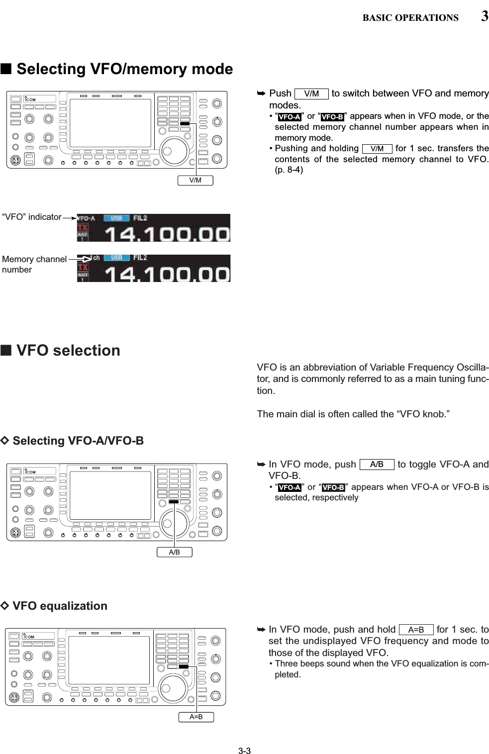
![3-4■Selecting an operating bandThe triple band stacking register provides 3 memoriesfor each band key, storing frequency and mode infor-mation.This function is convenient when you operate 3 modeson one band. For example, one register is used for aCW frequency, another for an SSB frequency and theother one for an RTTY frequency.If a band key is pushed once, the frequency and oper-ating mode last used are called up. When the key ispushed again, another stored frequency and operatingmode are called up.See the table below for a list of the bands availableand the default settings for each band.3BASIC OPERATIONSBAND REGISTER 1 REGISTER 2 REGISTER 31.8 MHz 1.900000 MHz CW 1.910000 MHz CW 1.915000 MHz CW3.5 MHz 3.550000 MHz LSB 3.560000 MHz LSB 3.580000 MHz LSB7 MHz 7.050000 MHz LSB 7.060000 MHz LSB 7.020000 MHz CW10 MHz 10.120000 MHz CW 10.130000 MHz CW 10.140000 MHz CW14 MHz 14.100000 MHz USB 14.200000 MHz USB 14.050000 MHz CW18 MHz 18.100000 MHz USB 18.130000 MHz USB 18.150000 MHz USB21 MHz 21.200000 MHz USB 21.300000 MHz USB 21.050000 MHz CW24 MHz 24.950000 MHz USB 24.980000 MHz USB 24.900000 MHz CW28 MHz 28.500000 MHz USB 29.500000 MHz USB 28.100000 MHz CW50 MHz 50.100000 MHz USB 50.200000 MHz USB 51.000000 MHz FMGeneral 15.000000 MHz USB 15.100000 MHz USB 15.200000 MHz USBDUsing the band stacking registersqPush , then select a frequency and an op-erating mode.• Frequency and operating mode are memorized in thefirst band stacking register.wPush again, then tune to another frequencyand operating mode.• This frequency and operating mode are memorized inthe second band stacking register.ePush again, then tune to another frequencyand operating mode.• This frequency and operating mode are memorized inthe third band stacking register.• When a fourth frequency and operating mode are se-lected on a band, the first register set in step q, is overwritten.14 514 514 5[Example]: 14 MHz band11.823.537410514618721824928GENE050ENTF-INPBand keys](https://usermanual.wiki/ICOM-orporated/300900.User-Manual-Part-1/User-Guide-900712-Page-43.png)
![3-5■Frequency settingThe transceiver has several tuning methods for conve-nient frequency tuning.DTuning with the main dialqPush the desired band key on the keypad 1–3times.• 3 different frequencies can be selected on each bandwith the band key.wRotate the main dial to set the desired frequency.If the dial lock function is activated, the lock indicatorlights, and the main dial does not function. In thiscase, push [LOCK] to deactivate the lock function.(see p. 5-17 for details)3BASIC OPERATIONS[EXAMPLE]7.00000 MHz21.24000 MHz21.24000 MHz ⇒ 21.36000 MHzPushPushPush11.823.523.537410618721ENTF-INPENTF-INPENTF-INPENTF-INPENTF-INPENTF-INPGENEGENE850 kHz (0.85000 MHz)PushENTF-INPENTF-INP GENE824050514KeypadDDirect frequency entry with the keypadThe transceiver has a keypad for direct frequencyentry as described below.qPush .• “ ” indicator appears and keypad backlight lights.wInput the desired frequency • Push to input “. (decimal point)” between theMHz units and kHz units.ePush to set the input frequency.• To cancel the input, push / instead of .F-INPENT√∫F-INPENTGENE •F-INPF-INPENTBand keysMain dial](https://usermanual.wiki/ICOM-orporated/300900.User-Manual-Part-1/User-Guide-900712-Page-44.png)
![3-6DQuick tuning stepThe operating frequency can be changed in largersteps (0.1, 1, 5, 9, 10, 12.5, 20 or 25 kHz selectable)for quick tuning.qPush [TS] to turn the quick tuning function ON.•“Z” appears when the quick tuning function is ON.wRotate the main dial to change the frequency in pro-grammed kHz steps.ePush [TS] again to turn OFF the indicator.rRotate the main dial for normal tuning if desired.3BASIC OPERATIONSQuick tuning indicatorD1⁄4tuning step functionWhen operating in SSB data, CW, RTTY or PSK, the1⁄4tuning function is available. Dial rotation is reducedto 1⁄4of normal speed when the 1⁄4tuning function isON for finer tuning control.➥Push [1/4] (MF6) to toggle the 1⁄4tuning function ONand OFF.• “ ” appears when the 1⁄4tuning function is ON.1⁄4DSelecting “kHz” stepqPush [TS] to turn the quick tuning function ON andOFF.•“Z” appears when the quick tuning function ON.wPush and hold [TS] for 1 sec. to enter quick tuningstep set mode.• Selected tuning steps for all modes appear.eSelect the desired operating mode.rRotate the main dial to select the desired tuning step.tRepeat steps eand rto select quick tuning stepsfor other modes, if desired.yPush to exit the setting display.NOTE: When entering quick tuning step set mode,the quick tuning function must be activated first.EXIT/SETMain dialSelect mode TS1/41⁄4 tuning step OFF 1⁄4 tuning step ON1/4ON1/4OFF](https://usermanual.wiki/ICOM-orporated/300900.User-Manual-Part-1/User-Guide-900712-Page-45.png)
![3-7DSelecting 1 Hz stepA minimum tuning step of 1 Hz can be used for finetuning.qPush [TS] to turn the quick tuning function OFF.wPush and hold [TS] for 1 sec. to turn the 1 Hz tuningstep ON and OFF.3BASIC OPERATIONSDBand edge warning beepWhen you tune outside of an amateur band’s frequencyrange, a warning beep sounds.This function can be turned OFF in set mode, if de-sired.qPush several times to close a multi-func-tion screen, if necessary.wPush [SET] to select set mode menu screen.• Pushing and holding for 1 sec. also selects setmode menu screen.ePush [OTHERS] to enter Others set mode.rPush [Y] or [Z] to select “Beep (BandEdge).”tRotate the main dial to turn the band edge warningbeep ON and OFF.yPush to exit the set mode.EXIT/SETF-2F-1F-5EXIT/SETF-7EXIT/SETEXIT/SETF-5OTHERSF-7SETF-1∫F-2√DAuto tuning step functionWhen rotating the main dial rapidly, the tuning speedaccelerates automatically as selected.qPush several times to close a multi-func-tion screen, if necessary.wPush [SET] to select set mode menu screen.• Pushing and holding for 1 sec. also selects setmode menu screen.ePush [OTHERS] to enter Others set mode.rPush [Y] or [Z] to select “MAIN DIALAuto TS.”tRotate the main dial to select the desired conditionfrom high, low and OFF.• High : Approx. 5 times faster• Low : Approx. twice faster• OFF : Auto tuning step is turned OFF.yPush to exit the set mode.EXIT/SETF-2F-1F-5EXIT/SETF-7EXIT/SET1Hz step indicator](https://usermanual.wiki/ICOM-orporated/300900.User-Manual-Part-1/User-Guide-900712-Page-46.png)
![3-9■Volume setting➥Rotate [AF] control clockwise to increase, counter-clockwise to decrease the audio output level.• Set a suitable audio level.3BASIC OPERATIONS■RF gain adjustment➥Rotate [RF] control clockwise to increase, counter-clockwise to decrease the receiver sensitivity.NOTE:When [RF] control is adjusted CCW in FM mode,audio output decreases then disappears. This is nor-mal, not a malfunction.■Squelch level adjustmentThe squelch mutes noise output from the speaker(closed squelch) when no signal is received.➥When no signal is received, rotate [SQL] controlfully counterclockwise first, then rotate [SQL] clock-wise to the point that the noise just disappears.• Push and hold to open the squelch temporar-ily.MONITOR[AF]Audio outputincreasesAudio outputdecreases[RF]SensitivityincreasesSensitivitydecreases[SQL]S-metersquelchNoise squelch(Recommended level; FM mode only)Squelch is openMONITOR](https://usermanual.wiki/ICOM-orporated/300900.User-Manual-Part-1/User-Guide-900712-Page-48.png)
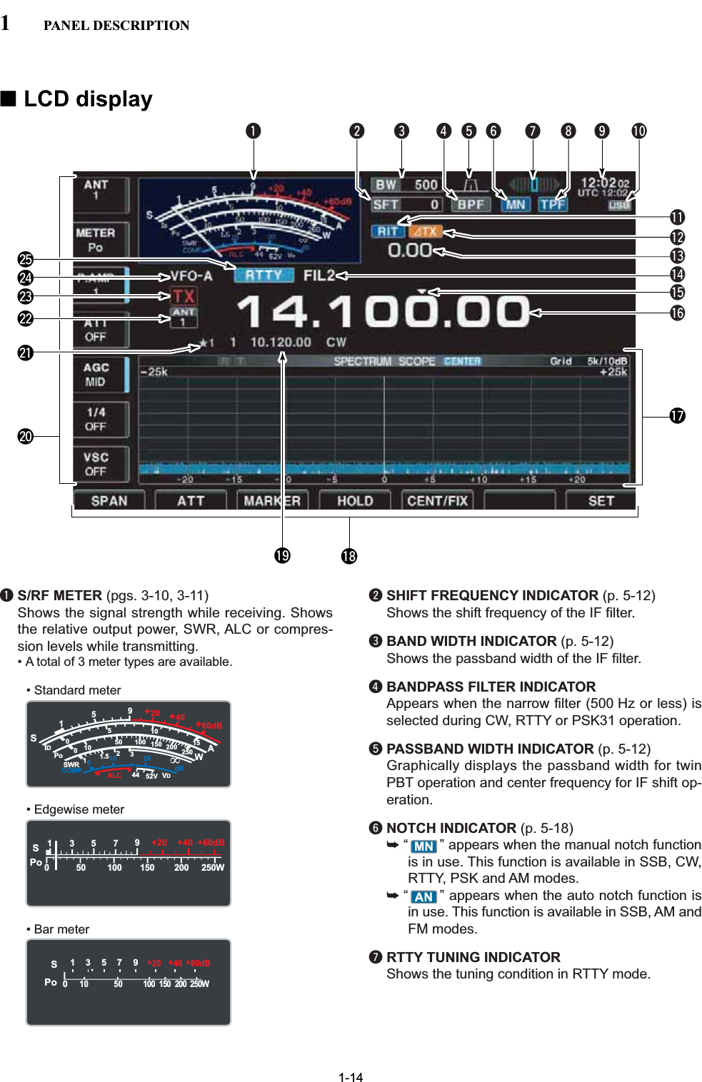
![DMulti-function digital meterThe IC-7700 can display the multi-function digitalmeter on the LCD display. This meter displays alltransmit parameters simultaneously.qPush and hold [METER] for 1 sec. to turn the multi-function digital meter ON.wPush [P-HOLD] to toggle the peak level holdfunction ON.• “ ” appears on the window title when the peaklevel hold function is ON.ePush and hold [METER] for 1 sec., or pushto turn the multi-function digital meterOFF.EXIT/SETP-HOLDF-1■Meter indication selectionThe S/RF meter indication, during transmit, can be se-lected from the following items as you desire.➥Push [METER] (MF2) several times to select the de-sired item.Indicates the RF output power in watts.Indicates the VSWR on the transmissionline.Indicates the ALC level. The ALC circuitbegins to activate when the RF outputpower reaches a preset level.Indicates the compression level whenthe speech compressor is in use.Indicates the drain current of the finalamplifier MOSFETs.Indicates the drain terminal voltage ofthe final amplifier MOSFETs.METERVDMETERIDMETERCOMPMETERALCMETERSWRMETERPo3-103BASIC OPERATIONS“P-HOLD” indicatorMETERMETER F-1P-HOLDS1000125101010 2044 52V50 100 150 200 2501531.5IDVDdBWAPoSWRCOMP ALC59+20 +40 +60dB'Signal strengthlevel readoutID readoutPower level readoutVSWR readoutCompression levelreadout ALC level readout VD readout](https://usermanual.wiki/ICOM-orporated/300900.User-Manual-Part-1/User-Guide-900712-Page-49.png)
![3-11DMeter type selectionA total of 3 meter types are available in the IC-7700—Standard, Edgewise and Bar meters. Follow the instructions below for the meter type selec-tion.qPush several times to return to normalscreen, if necessary.wPush [SET] , then push [DISP] to selectdisplay set mode.ePush [Y] or [Z] to select “Meter type(Normal Screen)” item.rRotate the main dial to select the desired meter typefrom “Standard,” “Edgewise” and “Bar.”tPush to exit display set mode.• Edgewise meter• Bar meterEXIT/SETF-2F-1F-3F-7EXIT/SET3BASIC OPERATIONSThe IC-7700 has built-in voice synthesizer to an-nounce the frequency, mode, etc. (S-meter level canalso be announced—p. 12-15) in clear, electroni-cally-generated voice, in English (or Japanese).➥Push to announce the currently se-lected frequency, etc.• Push and hold for 1 sec. to additionally an-nounce the selected mode.➥Pushing a mode switch also announces the ap-propriate mode. (p. 12-15)The output level of the voice synthesizer can beadjusted in level set mode. (p. 12-6)SPEECHSPEECH■Voice synthesizer operationEXIT/SETF-7SETF-3DISPF-1∫F-2√SPo13579250W200100 150500+20 +40 +60dBSPo1357 9250W200100 15050010+20 +40 +60dBSPEECH](https://usermanual.wiki/ICOM-orporated/300900.User-Manual-Part-1/User-Guide-900712-Page-50.png)
![3-12■Basic transmit operation3BASIC OPERATIONSDMicrophone gain adjustmentBefore transmitting, monitor your selected operatingfrequency to make sure transmitting won’t cause inter-ference to other stations on the same frequency. qPush [METER] (MF2) to select the ALC meter.wPush [PTT] (microphone) to transmit.• Talk into the microphone at your normal voice level.eWhile talking into the microphone, rotate [MIC] sothat the ALC meter reading doesn’t go outside theALC zone. (see at left)rRelease [PTT] (microphone) to return to receive.[MIC] METERS1000125101010 2044 52V50 100 150 200 2501531.5IDVDdBWAPoSWRCOMP ALC59+20 +40 +60dB∞ALC zone[TX] indicator[RF PWR]TRANSMITIncreasesmax. 200 W(50 W for AM)Decreasesmin. 5 WDTransmittingBefore transmitting, monitor your selected operatingfrequency to make sure transmitting won’t cause inter-ference to other stations on the same frequency. qPush or [PTT] (microphone) to transmit.• The [TX] indicator lights red.wPush again or release [PTT] (micro-phone) to return to receive.✔Adjusting the transmit output power➥Rotate [RF PWR].• Adjustable range : 5 W to 200 W (AM mode: 5 W to 50 W)TRANSMITTRANSMITBefore transmitting, monitor your selected oper-ating frequency to make sure transmitting won’tcause interference to other stations on the samefrequency. It’s good amateur practice to listenfirst, and then, even if nothing is heard, ask “isthe frequency in use” once or twice, before youbegin operating on that frequency.](https://usermanual.wiki/ICOM-orporated/300900.User-Manual-Part-1/User-Guide-900712-Page-51.png)
![3-13DDrive gain adjustmentThe drive gain is active for all modes other than SSBmode with speech compressor OFF. The [DRIVE] con-trol adjusts the amplifying gain at the driver stage.Before transmitting, monitor your selected operatingfrequency to make sure transmitting won’t cause inter-ference to other stations on the same frequency. qPush [METER] (MF2) to select the ALC meter.wPush [PTT] (microphone; SSB with [COMP] ON, AMor FM), key down (CW) or push (RTTYor PSK) to transmit.eWhile talking into the microphone, keying down ortransmitting, rotate [DRIVE] so that the ALC meterreading is between 30 to 50% of the ALC scale. (seeleft)• Talk into the microphone at your normal voice level.rRelease [PTT], stop keying or push again to return to receive.TRANSMITTRANSMIT3BASIC OPERATIONSS1000125101010 2044 52V50 100 150 200 2501531.5IDVDdBWAPoSWRCOMP ALC59+20 +40 +60dB∞Drive gain range[DRIVE]METER](https://usermanual.wiki/ICOM-orporated/300900.User-Manual-Part-1/User-Guide-900712-Page-52.png)
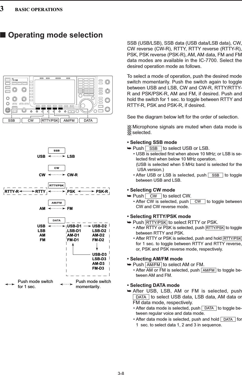
![4-2■Operating SSBqPush a band key to select the desired band.wPush to select LSB or USB.• “USB” or “LSB” appears.• Below 10 MHz LSB is automatically selected; above10 MHz USB is automatically selected.eRotate the main dial to tune a desired signal.• The S-meter indicates received signal strength when asignal is received.rRotate [AF] to set audio to a comfortable listeninglevel.tPush or [PTT] (microphone) to transmit.• [TX] indicator lights red.ySpeak into the microphone at your normal voicelevel.• Adjust the microphone gain with [MIC] at this step, ifnecessary.uPush or release [PTT] (microphone) toreturn to receive.TRANSMITTRANSMITSSB4RECEIVE AND TRANSMIT• Preamp (p. 5-9)➥Push [P.AMP] (MF3) several times to set the pre-amp OFF, preamp 1 ON or preamp 2 ON.• “P.AMP1” or “P.AMP2” appears when the preamp 1 orpreamp 2 is ON, respectively.• Attenuator (p. 5-9)➥Push [ATT] (MF4) several times to set the attenu-ator in 6 dB steps.• Push and hold [ATT] (MF4) for 1 sec. to turn theattenuator function OFF.• “ATT” and attenuation level appear when the attenu-ator is ON.• Noise blanker (p. 5-16)➥Push to turn the noise blanker ON andOFF, and then rotate [NB] control to adjust thethreshold level.• Noise blanker indicator (above switch) lightswhen the noise blanker is ON.• Push and hold for 1 sec. to enter noise blankerset mode.• Twin PBT (passband tuning) (p. 5-12)➥Rotate [TWIN PBT] controls (inner/outer).• PBT indicator (above switch) lights whenPBT is in use.• Push and hold for 1 sec. to clear the settings.• Audio tone control (p. 12-4)➥Push [SET] then [LEVEL] to enter levelset mode. Select an item with [Y] /[Z]then rotate the main dial to adjust the audio tone.• Noise reduction (p. 5-17)➥Push to turn the noise reduction ON andOFF.• Rotate [NR] control to adjust the noise reductionlevel.• Noise reduction indicator (above switch) lightswhen the noise reduction is ON.• Notch filter (p. 5-18)➥Push to turn the auto or manual notchfunction ON and OFF.• Rotate [NOTCH] control to set the “valley” frequencyfor manual notch operation.• Notch indicator (above switch) lights wheneither the auto or manual notch is ON.• AGC (auto gain control) (p. 5-11)➥Push [AGC] (MF5) switch several times to selectAGC FAST, AGC MID or AGC SLOW.➥Push to turn the AGC time constantmanual setting ON and OFF.• Rotate [AGC] control to adjust the time constant.• VSC (voice squelch control) (p. 9-3)➥Push [VSC] (MF7) to turn the VSC function ONand OFF.• The VSC indicator appears when the voice squelchfunction is set to ON.AGC VRNOTCHNOTCHNRNRF-2F-1F-1F-7PBT-CLRPBT-CLRNBNBNBDConvenient functions for receive[MIC] [TX] indicator [RX] indicator[AF] Main dialBand keysSSBTRANSMITAppears](https://usermanual.wiki/ICOM-orporated/300900.User-Manual-Part-1/User-Guide-900712-Page-55.png)
![DAbout 5 MHz band operation (USA version only)Operation on the 5 MHz band is allowed on 5 discretefrequencies and must adhere to the following: • USB mode• Maximum of 50 watts ERP (Effective Radiated Power)• 2.8 kHz bandwidthIt’s your responsibility to set all controls so that trans-mission in this band meets the stringent conditionsunder which amateur operations may use these fre-quencies.NOTE: We recommend that you store these fre-quencies, mode and filter settings into memorychannels for easy recall. *The FCC specifies center frequencies on the5 MHz band. However, the IC-7700 displays carri-er frequency. Therefore, tune the transceiver to1.5 kHz below the specified FCC channel centerfrequency.4-34RECEIVE AND TRANSMITIC-7700 Tuning FCC ChannelFrequency* Center Frequency*5.33050 MHz 5.33200 MHz5.34650 MHz 5.34800 MHz5.36650 MHz 5.36800 MHz5.37150 MHz 5.37300 MHz5.40350 MHz 5.40500 MHzTo assist you in operating the 5 MHz band within therules specified by the FCC, transmission is illegal onany 5 MHz band frequency other than the five fre-quencies indicated in the table above.• Speech compressor (p. 6-5)➥Push [COMP] (MF6) to turn the speech compres-sor ON and OFF.• Push and hold [COMP] (MF6) for 1 sec. to select thecompression bandwidth from wide, middle and nar-row.• VOX (voice operated transmit) (p. 6-2)➥Push to turn the VOX function ON andOFF.• “ ” appears when the VOX function is ON.• Transmit quality monitor (p. 6-4)➥Push to turn the monitor function ONand OFF.• Rotate [MONI GAIN] to adjust the monitor gain.• Monitor indicator (above switch) lightswhen the monitor function is ON.• Audio tone control (p. 12-5)➥Push [SET] then [LEVEL] to enter levelset mode. Select an item with [Y] /[Z]then rotate the main dial to adjust the audio tone.F-2F-1F-1F-7MONITORMONITORVOXVOXDConvenient functions for transmit](https://usermanual.wiki/ICOM-orporated/300900.User-Manual-Part-1/User-Guide-900712-Page-56.png)
![4-4■Operating CWqPush a band key to select the desired band.wPush to select CW.• After CW mode is selected, push to toggle be-tween CW and CW-R modes.• “CW” or “CW-R” appears.eRotate the main dial to tune a desired signal.• Try to match the specified signal’s tone to the side tonefrequency.• The S-meter indicates received signal strength whensignal is received.rRotate [AF] to set audio to a comfortable listeninglevel.tPush to transmit.• [TX] indicator lights red.yUse the electric keyer or paddle to key your CW sig-nals.• The power meter indicates transmitted CW outputpower.uAdjust CW speed with [KEY SPEED].• Adjustable within 6–48 WPM.iPush to return to receive.TRANSMITTRANSMITCWCW4RECEIVE AND TRANSMIT• Preamp (p. 5-9)➥Push [P.AMP] (MF3) several times to set the pre-amp OFF, preamp 1 ON or preamp 2 ON.• “P.AMP1” or “P.AMP2” appears when the preamp 1 orpreamp 2 is ON.• Attenuator (p. 5-9)➥Push [ATT] (MF4) several times to set the attenu-ator in 6 dB steps.• Push and hold [ATT] (MF4) for 1 sec. to turn theattenuator function OFF.• “ATT” and attenuation level appear when the attenu-ator is ON.• Noise blanker (p. 5-16)➥Push to turn the noise blanker ON andOFF, and then rotate [NB] control to adjust thethreshold level.• Noise blanker indicator (above switch) lightswhen the noise blanker is ON.• Push and hold for 1 sec. to enter noise blankerset mode.• Noise reduction (p. 5-17)➥Push to turn the noise reduction ON andOFF.• Rotate [NR] control to adjust the noise reductionlevel.• Noise reduction indicator (above switch) lightswhen the noise reduction is ON.• Twin PBT (passband tuning) (p. 5-12)➥Rotate [TWIN PBT] controls (inner/outer).• PBT indicator (above switch) lights whenPBT is in use.• Push and hold for 1 sec. to clear the set-tings.• Manual notch filter (p. 5-18)➥Push to turn the manual notch functionON and OFF.• Rotate [NOTCH] control to set the attenuating fre-quency.• Notch indicator (above switch) lights whenthe manual notch is ON.• AGC (auto gain control) (p. 5-11)➥Push [AGC] switch several times to selectAGC FAST, AGC MID or AGC SLOW.➥Push to turn the AGC time constantmanual setting ON and OFF.• Rotate [AGC] control to adjust the time constant.•1⁄4function (p. 3-6)➥Push [1/4] to turn the 1⁄4function ON and OFF.• Auto tuning function (p. 5-19)➥Push [AUTOTUNE] to turn the auto tuning func-tion ON and OFF.• The transceiver automatically tunes the desired sig-nal within a ±500 Hz range.IMPORTANT!When receiving a weak signal, or receiving a signalwith interference, the automatic tuning function maynot tune properly, or tune onto an undesired signal.AGC VRNOTCHNOTCHPBT-CLRPBT-CLRNRNRNBNBNBDConvenient functions for receive[KEY SPEED] [TX] indicator [RX] indicator[AF] Main dialBand keysCWTRANSMITAppears](https://usermanual.wiki/ICOM-orporated/300900.User-Manual-Part-1/User-Guide-900712-Page-57.png)
![4-5DAbout CW reverse modeCW-R (CW Reverse) mode uses the opposite sideband to receive CW signals.Use when interfering signals are near a desired signaland you want to use CW-R to reduce the interference.➥During CW mode, push to select CW andCW-R mode.DAbout CW pitch controlThe received CW audio pitch and CW side tone canbe adjusted to suit your preference (from 300 to900 Hz in 5 Hz steps). This does not change the oper-ating frequency.➥Rotate [CW PITCH] to suit your preference.• Adjustable within 300 to 900 Hz in 5 Hz steps.DCW side tone functionWhen the transceiver is in receive (and the break-infunction is OFF— p. 6-3) you can listen to the CW sidetone without actually transmitting. This allows you to match your transmit frequency ex-actly to another station’s by matching the audio tone.You can also use the CW side tone (be sure to turnOFF break-in!) to practice CW sending. CW side tonelevel can be adjusted in level set mode (p. 12-6).CWPushBFOCW-R mode (USB side)BFODesired signalCW mode (LSB side)Interference Desired signalInterference[CW PITCH][MONI GAIN]4RECEIVE AND TRANSMIT• Break-in function (p. 6-3)➥Push several times to select the break-inOFF, semi break-in and full break-in.• “ ” or “ ” appears when the semi break-in or full break-in function is ON, respectively.F-BKINBKINBK-INDConvenient functions for transmit](https://usermanual.wiki/ICOM-orporated/300900.User-Manual-Part-1/User-Guide-900712-Page-58.png)
![4-6DAPF (Audio Peak Filter) operationThe APF changes the audio frequency response byboosting a particular frequency to enhance a desiredCW signal. The peak frequency can be adjusted with [DIGI-SEL]control when “APF” is selected for “DIGI-SEL VR Op-eration” in Others set mode (p. 12-16).The audio filter shape is also selectable from “SOFT”and “SHARP” in Others set mode (p. 12-16).qDuring CW mode, push to turn the audiopeak filter ON and OFF.• “ ” appears in the display and [APF/TPF] indicatorabove this switch lights green.wPush and hold for 1 sec. several times toselect the desired audio filter width.• WIDE, MID and NAR filters, or, 320, 160 and 80 Hz fil-ters are available depending on APF type setting in levelset mode.eIf “APF” is selected for “DIGI-SEL VR Operation,”rotate [DIGI-SEL] control to suit your preference.APF/TPFAPFAPF/TPF[DIGI-SEL]APF/TPF4RECEIVE AND TRANSMIT](https://usermanual.wiki/ICOM-orporated/300900.User-Manual-Part-1/User-Guide-900712-Page-59.png)
![4-7■Electronic keyer functionsThe IC-7700 has a number of convenient functions forthe built-in electronic keyer.qDuring CW mode, push several times tonormal screen, if necessary.wPush [KEYER] to select memory keyer screen.ePush to select memory keyer menuscreen.rPush one of the LCD function switches ( to) to select the desired menu. See the diagrambelow.• Push to return to the previous display.EXIT/SETF-4F-1EXIT/SETF-3EXIT/SET• Memory keyer screen (p. 4-8)• Memory keyer menu screen• Memory keyer edit screen (p. 4-9)• Contest number set mode (p. 4-10)• Keyer set mode screen (p. 4-11)F-1 F-2 F-3 F-4 F-5 F-6 F-7F-1F-1 F-2F-3F-4F-2 F-3 F-4 F-5 F-6 F-7EXIT/SET–EXIT/SETCWF-1 F-44RECEIVE AND TRANSMIT](https://usermanual.wiki/ICOM-orporated/300900.User-Manual-Part-1/User-Guide-900712-Page-60.png)
![4-8DMemory keyer screenPre-set characters can be sent using the keyer sendmenu. Contents of the memory keyer are set using theedit menu.• TransmittingqDuring CW mode operation, push [KEYER] toselect memory keyer screen.wPush to set the transceiver to transmit,or set the break-in function ON (p. 6-3).ePush one of the function keys ([M1] to [M4]) to send the contents of the memory keyer.• Pushing and holding a function key for 1 sec. repeatedlysends the contents; push any function key to cancel thetransmission.• The contest serial number counter is incremented eachtime the contents are sent.• Push [–1] to reduce the contest serial numbercount by 1 when resending contents to unansweredcalls.For your informationWhen an external keypad is connected to [EXTKEYPAD] connector on the rear panel, the pro-grammed contents, M1—M4, can be transmittedwithout selecting the memory keyer screen.See p. 2-7 for details.rPush twice to return to normal screen.EXIT/SETF-5F-4F-1TRANSMITF-3–EXIT/SETCWTRANSMITF-1M1F-4M4F-5–14RECEIVE AND TRANSMIT• Memory keyer screen](https://usermanual.wiki/ICOM-orporated/300900.User-Manual-Part-1/User-Guide-900712-Page-61.png)
![4-9DEditing a memory keyer The contents of the memory keyer memories can beset using the memory keyer edit menu. The memorykeyer can memorize and re-transmit 4 CW key codesfor often-used CW sentences, contest serial numbers,etc. Total capacity of the memory keyer is 70 charac-ters per memory channel.• Programming contentsqDuring CW mode operation, push [KEYER] toselect memory keyer screen.wPush to select memory keyer menu, thenpush [EDIT] to select keyer edit screen.• Memory keyer contents of Channel 1 (M1) is selected.ePush [M1..M4] several times to select the de-sired memory keyer channel to be edited.rPush [ABC] (MF6) or [123] (MF7) or [Symbol] (MF7)to select the character group, then rotate the maindial to select the character, or push the keypad fornumber input.• [Symbol] appears when [123] (MF7) is pushed when“123” character group is selected.• Selectable characters (using the main dial);NOTE:“^” is used to transmit a following word with nospace such as AR. Put “^” before a text stringsuch as ^AR, and the string “AR ” is sent with nospace.“✱” is used to insert the CW contest serial num-ber. The serial number automatically incrementsby 1. This function is only available for one mem-ory keyer channel at a time. Memory keyer chan-nel M2 used “✱” by default.✔For your convenienceWhen a PC keyboard is connected to [USB] con-nector on the front panel, the memory keyer con-tents can also be edited from the keyboard.tPush [Ω] or [≈] to move the cursorbackwards or forwards, respectively.• Pushing [DEL] deletes a character and [SPACE]inserts a space.yRepeat steps rand tto input the desired charac-ters.uPush twice to return normal screen.EXIT/SETF-4F-3F-2F-1F-7F-2EXIT/SETF-3/F-1ΩF-2≈F-7M1..M4F-3DELF-4SPACE123 Symbol ABCEXIT/SET4RECEIVE AND TRANSMIT• Memory keyer edit screenKey selection Editable charactersA to Z (capital letters)0 to 9 (numbers)/ ? ^ . , @ ✱Symbol123ABC• Example— entered “QSL TU DE JA3YUA TEST”into memory keyer channel 3CH ContentsM1 CQ TEST CQ TEST DE ICOM ICOM TESTM2 UR 5NN✱BKM3 CFM TUM4 QRZ?• Pre-programmed contents](https://usermanual.wiki/ICOM-orporated/300900.User-Manual-Part-1/User-Guide-900712-Page-62.png)
![4-10DContest number set modeThis menu is used to set the contest (serial) numberand count-up trigger, etc.• Setting contentsqDuring CW mode operation, push [KEYER] toselect memory keyer screen.wPush to select memory keyer menu, thenpush [001] to select contest serial number setmode.ePush [Y] or [Z] to select the desired setitem.rSet the desired condition using the main dial.• Push and hold [DEF] for 1 sec. to select the de-fault condition or value.• Contest number set mode screen tPush twice to normal screen.EXIT/SETF-4F-2F-1F-3EXIT/SETF-3Main dialF-1∫F-2√EXIT/SETF-4DEF4RECEIVE AND TRANSMITThis item sets the numbering system used for contest(serial) numbers— normal or short morse numbers.• Normal : Does not use short morse numbers(default)• 190➔ANO : Sets 1 as A, 9 as N and 0 as O.• 190➔ANT : Sets 1 as A, 9 as N and 0 as T.•90➔NO : Sets 9 as N and 0 as O.•90➔NT : Sets 9 as N and 0 as T.This selects which of the four memories will containthe contest serial number exchange. The count-uptrigger allows the serial number to automatically in-crement after each complete serial number exchangeis sent.• M1, M2, M3 and M4 can be set. (default: M2)This item shows the current number for the count-uptrigger channel set above.• Rotate the main dial to change the number, or pushand hold [001CLR] for 1 sec. to reset the cur-rent number to 001.F-3Number StyleNormalCount Up TriggerM2Present Number001](https://usermanual.wiki/ICOM-orporated/300900.User-Manual-Part-1/User-Guide-900712-Page-63.png)
![4-11DKeyer set modeThis set mode is used to set the memory keyer repeattime, dash weight, paddle specifications, keyer type,etc.• Setting contentsqDuring CW mode operation, push [KEYER] toselect memory keyer screen.wPush to select memory keyer menu, thenpush [CW KEY] to select keyer set mode.ePush [Y] or [Z] to select the desired setitem.rSet the desired condition using the main dial.• Push and hold [DEF] for 1 sec. to select the de-fault condition or value.tPush twice to normal screen.• Keyer set mode screenEXIT/SETF-4F-2F-1F-4EXIT/SETF-3Main dialF-1∫F-2√EXIT/SETF-4DEF4RECEIVE AND TRANSMITWhen sending CW using the repeat timer, this itemsets the time between transmission.• 1 to 60 sec. in 1 sec. steps can be selected. (default: 2 sec.)This item sets the dot/dash ratio.Keying weight example: Morse code “K”• 1:1:2.8 to 1:1:4.5 (in 0.1 steps) can be selected.(default: 1:1:3.0)DASHWeight setting:1:1:3 (default)Weight setting:AdjustedDASHDOT (fixed*)Adjustable range SPACE (fixed*)*SPACE and DOT length can be adjusted with [KEY SPEED] only.This item sets the rise time of the transmitted CW en-velope.• 2, 4, 6 or 8 msec. can be selected. (default: 4 msec.)Key actionTx output power• About rise timeRise timeTxRxSet Tx power levelTime0to be continued…Dot/Dash Ratio1:1:3.0Rise Time4msKeyer Repeat Time2s](https://usermanual.wiki/ICOM-orporated/300900.User-Manual-Part-1/User-Guide-900712-Page-64.png)
![4-12DKeyer set mode (continued)4RECEIVE AND TRANSMITThis item sets the paddle polarity. • Normal and reverse polarity can be selected.This item selects the keyer type for [ELEC-KEY] con-nector on the front panel.• ELEC-KEY, BUG-KEY and Straight key can be se-lected. (default: ELEC-KEY)This item allows you to set the microphone [UP]/[DN]keys to be used as a paddle.•ON :[UP]/[DN] switches can be used for CW.•OFF :[UP]/[DN] switches cannot be used forCW.NOTE: When “ON” is selected, the frequency andmemory channel cannot be changed usingthe [UP]/[DN] switches.Keyer TypeELE-KEYMic Up/Down KeyerOFFPaddle PolarityNormal](https://usermanual.wiki/ICOM-orporated/300900.User-Manual-Part-1/User-Guide-900712-Page-65.png)
![4-13■Operating RTTY (FSK)A DSP-based high-quality Baudot RTTY encoder/de-coder is built-in to the IC-7700. When connecting a PCkeyboard (p. 2-6), RTTY operation can be performedwithout an external RTTY terminal, TNC or PC.If you would rather use your RTTY terminal or TNC,consult the manual that comes with the RTTY terminalor TNC.qPush a band key to select the desired band.wPush to select RTTY.• After RTTY mode is selected, push and hold for 1 sec. to toggle between RTTY and RTTY-R modes.• “RTTY” or “RTTY-R” appears.ePush [DECODE] to display the decode screen.• The IC-7700 has a built-in Baudot decoder.rTo tune the desired signal, aim for a symmetricalwaveform and ensure the peak points align with themark (2125 Hz) and shift (170 Hz) frequency linesin the FFT scope. • The S-meter indicates received signal strength whensignal is received.tPress [F12] on the connected keyboard to transmit.• [TX] indicator lights red.yType from the keyboard to enter the contents thatyou want to transmit.• The typewritten contents are indicated in the TX bufferscreen and transmitted immediately.• The text color will be changed when transmitted. • Press one of [F1]–[F8] to transmit the TX memory con-tents.uPress [F12] on the keyboard to return to receive.✔For your convenienceThe transmission contents can be typed before beingtransmitted.qPerform the steps qto rabove.wType from the connected keyboard to enter themessage that you want to transmit.• The typewritten contents are indicated in the TX bufferscreen.ePress [F12] of the connected keyboard to transmitthe typewritten contents.• The color of displayed text, in the TX buffer screen, willbe changed when transmitted. • To cancel the transmission, press [F12] twice.rPress [F12] of the keyboard to return to receive.F-3RTTY/PSKRTTY/PSKFFT scopeTX buffer screenRX contents screenWater-fallAppears[TX] indicator [RX] indicator[AF] Main dialBand keysRTTY/PSKF-3DECODE4RECEIVE AND TRANSMIT](https://usermanual.wiki/ICOM-orporated/300900.User-Manual-Part-1/User-Guide-900712-Page-66.png)
![4-14DAbout RTTY reverse modeReceived characters are occasionally garbled whenthe received signal has Mark and Space tones re-versed. This reversal can be caused by incorrect TNCconnections, setting, commands, etc. To receive re-versed RTTY signals correctly, select RTTY-R mode.➥During RTTY mode, push and hold for1 sec. to select RTTY and RTTY-R mode.DTwin peak filterThe twin peak filter changes audio frequency responseby boosting the mark and space frequencies (2125 and2295 Hz) for better reception of RTTY signals.➥During RTTY mode, push to turn the twinpeak filter ON and OFF.• “ ” appears in the LCD and the [APF/TPF] indicatorabove this switch lights green while the filter is in use.NOTE: When the twin peak filter is in use, the re-ceived audio output may increase. This is a normal,not a malfunction.TPFAPF/TPFRTTY/PSKAPF/TPFNormal ReverseSpace Mark BFO Space MarkBFO170 Hz 2125 Hz 170 Hz2125 Hz4RECEIVE AND TRANSMIT• Preamp (p. 5-9)➥Push [P.AMP] (MF3) several times to set the pre-amp OFF, preamp 1 ON or preamp 2 ON.• “P.AMP1” or “P.AMP2” appears when the preamp 1 orpreamp 2 is ON.• Attenuator (p. 5-9)➥Push [ATT] (MF4) several times to set the attenu-ator in 6 dB steps.• Push and hold [ATT] (MF4) for 1 sec. to turn the atten-uator function OFF.• “ATT” and attenuation level appear when the attenu-ator is ON.• Noise blanker (p. 5-16)➥Push to turn the noise blanker ON andOFF, and then rotate [NB] control to adjust thethreshold level.• Noise blanker indicator (above switch) lightswhen the noise blanker is ON.• Push and hold for 1 sec. to enter noise blankerset mode.• Twin PBT (passband tuning) (p. 5-12)➥Rotate [TWIN PBT] controls (inner/outer).• PBT indicator (above switch) lights whenPBT is in use.• Push and hold for 1 sec. to clear the set-tings.• Noise reduction (p. 5-17)➥Push to turn the noise reduction ON andOFF.• Rotate [NR] control to adjust the noise reductionlevel.• Noise reduction indicator (above switch) lightswhen the noise reduction is ON.• Manual notch filter (p. 5-18)➥Push to turn the manual notch functionON and OFF.• Rotate [NOTCH] control to set the attenuating fre-quency.• Notch indicator (above switch) lights whenthe manual notch is ON.• AGC (auto gain control) (p. 5-11)➥Push [AGC] switch several times to selectAGC FAST, AGC MID or AGC SLOW.➥Push to turn the AGC time constantmanual setting ON and OFF.• Rotate [AGC] control to adjust the time constant.•1⁄4function (p. 3-6)➥Push [1/4] to turn the 1⁄4function ON and OFF.AGC VRNOTCHNOTCHNRNRPBT-CLRPBT-CLRNBNBNBDConvenient functions for receive](https://usermanual.wiki/ICOM-orporated/300900.User-Manual-Part-1/User-Guide-900712-Page-67.png)
![4-15DFunctions for the RTTY decoder indicationqPush a band key to select the desired band.wPush to select RTTY.• After RTTY mode is selected, push and hold for 1 sec. to toggle between RTTY and RTTY-R modes.• “RTTY” or “RTTY-R” appears.ePush [DECODE] to display the decode screen.• When tuned into an RTTY signal, decoded charactersare displayed in the RX contents screen.rPush [HOLD/CLR] to freeze the current screen.• “ ” appears while the function is in use.• Push [HOLD/CLR] again to release the function.tPush and hold [HOLD/CLR] for 1 sec. to clearthe displayed characters.•“ ” indicator disappears at the same time when thehold function is in use.yPush [WIDE] to toggle the RTTY decodescreen size from normal and wide.• S/RF meter type during wide screen indication can beselected in display set mode. (pgs. 3-11, 12-10)uPush to close the RTTY decode screen.• Wide screen indicationDSetting the decoder threshold levelAdjust the RTTY decoder threshold level if some char-acters are displayed when no signal is received.qSelect the RTTY decode screen as describedabove.wPush [ADJ] to select the threshold level set-ting condition.eRotate the main dial to adjust the RTTY decoderthreshold level.• Push and hold [DEF] for 1 sec. to select the de-fault setting.rPush [ADJ] to exit from the threshold level set-ting condition.The UnShift On Space (USOS) function and newline code can be set in the RTTY set mode. (p. 4-18)F-5F-6F-5EXIT/SETF-7HOLDF-2F-2HOLDF-2F-3RTTY/PSKRTTY/PSKRTTY/PSK EXIT/SETF-7WIDEF-2HOLD/CLR4RECEIVE AND TRANSMIT](https://usermanual.wiki/ICOM-orporated/300900.User-Manual-Part-1/User-Guide-900712-Page-68.png)
![4-16DRTTY memory transmissionPre-set characters can be sent using the RTTY mem-ory. Contents of the memory are set using the editmenu.qDuring RTTY mode operation, push [DECODE]to select RTTY decode screen.wPush [TX MEM] to select RTTY memoryscreen.ePush [1–4/5–8] to select memory bank thenpush one of the function keys ([RT1] to [RT4] or [RT5] to [RT8] ). • When no keyboard is connected, the selected memorycontents will be transmitted immediately.• When a keyboard is connected, the memory contentswill be transmitted immediately when function key ispushed, or transmitted after [F12] on the connected key-board is pressed, depending on auto transmission/re-ception setting (see below).• The transmission date, time, reception date and/or timemay be displayed in RX contents screen, depending onsetting.DAutomatic transmission/reception settingqDuring RTTY mode operation, push [F-3•DECODE]to select RTTY decode screen.wPush [TX MEM] to select RTTY memoryscreen, then push [EDIT] to select RTTYmemory edit screen.• RTTY memory contents of the Channel 1 (RT1) is se-lected.ePush [RT1..RT8] several times to select thedesired RTTY memory.rPush [AUTO TX] several times to select thedesired condition as follow.• AUTO TX/RX : Automatically transmits the se-lected memory and returns to re-ceive after the transmission.• AUTO TX : Automatically transmits the se-lected memory. To return to re-ceive, press [F12] on the key-board.• AUTO RX : Press [F12] on the keyboard totransmit the selected memory. Au-tomatically returns to receive afterthe transmission.• No indication : Press [F12] on the keyboard totransmit the selected memory andpress [F12] again to return to re-ceive.tPush to exit RTTY memory edit condition.NOTE: The transceiver always functions in the“AUTO TX/RX” setting when no keyboard is con-nected.EXIT/SETF-6F-7F-6F-4F-4F-1F-4F-1F-7F-4F-3EXIT/SETF-7RT1..RT8F-6AUTO TX ––or F-71–4/5–8F-1RT1F-4RT4F-1RT5F-4RT8 EXIT/SET4RECEIVE AND TRANSMIT](https://usermanual.wiki/ICOM-orporated/300900.User-Manual-Part-1/User-Guide-900712-Page-69.png)
![4-17DEditing RTTY memory The contents of the RTTY memories can be set usingthe memory edit menu. The memory can store and re-transmit 8 RTTY message for often-used RTTY infor-mation. Total capacity of the memory is 70 charactersper memory channel.• Programming contentsqDuring RTTY mode operation, push [F-3•DECODE]to select RTTY decode screen.wPush [TX MEM] to select RTTY memoryscreen, then push [EDIT] to select RTTYmemory edit screen.• RTTY memory contents of the Channel 1 (RT1) is se-lected.ePush [RT1..RT8] to several times to select thedesired RTTY memory channel to be edited.rPush [Ω≈] to select the edit item betweenmemory contents and memory name.tPush [ABC] (MF6), [abc] (MF6), [123] (MF7) or [Sym-bol] (MF7) to select the character group, then rotatethe main dial to select the character, or push thekeypad for number input.• [abc] (MF6) appears when [ABC] (MF6) is pushed when“ABC” character group is selected, and [Symbol] (MF7)appears when [123] (MF7) is pushed when “123” char-acter group is selected.• Selectable characters (with the main dial);✔For your convenienceWhen a PC keyboard is connected to [USB] con-nector on the front panel, the RTTY memory con-tents can also be edited from the keyboard.yPush [Ω] or [≈] to move the cursorbackwards or forwards, respectively.• Pushing [DEL] deletes a character and [SPACE]inserts a space.uRepeat steps tand yto input the desired charac-ters.iPush to set the contents and exit RTTYmemory edit screen.EXIT/SETF-4F-3F-2F-1F-5F-7F-6F-4RT1..RT8EXIT/SETF-7//F-3DELF-4SPACE123 Symbol ABC abcF-1ΩF-2≈F-5Ω ≈4RECEIVE AND TRANSMIT• RTTY memory edit screenKey selection Editable charactersA to Z (capital letters)a to z (small letters) (selectable for memory name only)0 to 9 (numbers)! # $ % & ¥ ? “ ‘ ` ^ + – ✱/ . , : ; =< > ( ) [ ] { } | _ ~@(For the memory contents set-ting, ! $ & ? “ ‘ – / . , : ; ( ) ¿areselectable.)Symbol123abcABCCH Name ContentsRT1 MYCALLx2 ¿DE ICOM ICOM K¿RT2 MYCALLx3 ¿DE ICOM ICOM ICOM K¿RT3 QSLUR599 ¿QSL UR 599–599 BK¿RT4 DE+UR599 ¿QSL DE ICOM ICOM UR 599–599BK¿RT5 73 GL SK ¿73 GL SK¿RT6 CQ CQ CQ ¿CQ CQ CQ DE ICOM ICOM ICOMK¿RT7 RIG&ANT ¿MY TRANSCEIVER IS IC–7700 &ANTENNA IS A 3–ELEMENTTRIBAND YAGI.¿RT8 EQUIP. ¿MY RTTY EQUIPMENT IS INTERNAL FSK UNIT & DEMODULATOR OF THEIC–7700.¿• Pre-programmed contents](https://usermanual.wiki/ICOM-orporated/300900.User-Manual-Part-1/User-Guide-900712-Page-70.png)
![4-18DRTTY decode set modeThis set mode is used to set the decode USOS func-tion, time stamp setting, etc.• Setting contentsqDuring RTTY mode operation, push [DECODE]to select RTTY decode screen.wPush [<MENU1>] to select the second RTTYdecode menu, then push [SET] to selectRTTY decode set mode.• Push [WIDE] to toggle the screen size from normaland wide.ePush [Y] or [Z] to select the desired setitem.rSet the desired condition using the main dial.• Push and hold [DEF] for 1 sec. to select a defaultcondition or value.• Push [Ω≈] to select the set contents for someitems.tPush to exit from set mode.EXIT/SETF-3F-4F-2F-1F-7F-6F-1F-3F-3 F-7WIDEΩ ≈Main dialEXIT/SETDEFF-1∫F-2√F-44RECEIVE AND TRANSMIT• RTTY decode set mode screenTurn the capability of letter code decoding after re-ceiving a “space” (USOS; UnShift On Space function)ON and OFF.• ON : Decode as letter code.• OFF : Decode as character code.Selects the new line code of the internal RTTY de-coder.CR: Carriage Return, LF: Line Feed• CR,LF,CR+LF : Makes new line with any codes.• CR+LF : Makes new line with CR+LF codeonly.RTTY Decode USOSONRTTY Decode New Line CodeCR,LF,CR+LFSelects the diddle condition. • BLANK : Transmits blank code during no codetransmission.• LTRS : Transmits letter code during no codetransmission.• OFF : Turns the diddle function OFF.RTTY DiddleBLANKSelect the FFT scope waveform averaging functionfrom 2 to 4 and OFF. (default: OFF)Recommendation!If you use the FFT scope waveform for tuning, use thedefault or smaller number setting is recommended.RTTY FFT Scope AveragingOFFSet the color for the FFT scope waveform.• The color is set in RGB format.• The set color is indicated in the box beside the RGB scale.• Push [Ω≈] to select R (Red), G (Green) and B (Blue),and then rotate the main dial to set the ratio from 0 to 255.F-3RTTY FFT Scope Waveform Color51 153 255](https://usermanual.wiki/ICOM-orporated/300900.User-Manual-Part-1/User-Guide-900712-Page-71.png)
![4-19DRTTY decode set mode (continued)4RECEIVE AND TRANSMITExplicitly inserts the FIGS character even though it isnot required by the receiving station.• ON : Inserts FIGS.• OFF : Does not insert FIGS.RTTY TX USOSONTurn the time stamp (date, transmission or receptiontime) indication ON and OFF.• ON : Displays the time stamp.• OFF : No time stamp indication.Selects the clock indication for time stamp usage.NOTE: The time won’t be displayed when “OFF” isselected in “RTTY Time Stamp” as above.• Local : Selects the time that set in “Time (Now).”• UTC* : Selects the time that set in “CLOCK2.”*The name of choice may differ according to“CLOCK2 Name” setting (p. 11-2). “UTC” is thedefault name of CLOCK2. RTTY Time StampONRTTY Time Stamp (Time)LocalSelects the automatic new line code (CR+LF) trans-mission capability.• ON : Transmits CR+LF code once.• OFF : Transmits no CR+LF code.RTTY Auto CR+LF by TXONSet the text color for transmitted characters.• The color is set in RGB format.• The set color is indicated in the box beside the RGB scale.• Push [Ω≈] to select R (Red), G (Green) and B (Blue),and then rotate the main dial to set the ratio from 0 to 255.F-3RTTY Font Color (Transmit)255 106 106Selects the operating frequency indication for timestamp usage.NOTE: The frequency won’t be displayed when “OFF”is selected in “RTTY Time Stamp” as above.• ON : Displays the operating frequency.• OFF : No operating frequency display.Set the text color for received characters.• The color is set in RGB format.• The set color is indicated in the box beside the RGB scale.• Push [Ω≈] to select R (Red), G (Green) and B (Blue),and then rotate the main dial to set the ratio from 0 to 255.F-3RTTY Time Stamp (Frequency)OFFRTTY Font Color (Receive)128 255 128Set the text color for time stamp indication.• The color is set in RGB format.• The set color is indicated in the box beside the RGB scale.• Push [Ω≈] to select R (Red), G (Green) and B (Blue),and then rotate the main dial to set the ratio from 0 to 255.F-3Set the text color in the TX buffer screen.• The color is set in RGB format.• The set color is indicated in the box beside the RGB scale.• Push [Ω≈] to select R (Red), G (Green) and B (Blue),and then rotate the main dial to set the ratio from 0 to 255.F-3RTTY Font Color (Time Stamp)0155 189RTTY Font Color (TX Buffer)255 255 255](https://usermanual.wiki/ICOM-orporated/300900.User-Manual-Part-1/User-Guide-900712-Page-72.png)
![4-20DData savingThe contents of the RTTY memory and received sig-nal can be saved into the USB-Memory.qDuring RTTY decode screen indication, push [<MENU1>] to select the RTTY decode sec-ond menu.wPush [SAVE] to select decode file save screen.eChange the following conditions if desired.• File name:zPush [EDIT] to select file name edit con-dition.• Push [DIR/FILE] several times to select thefile name, if necessary.xPush [ABC] (MF6), [123] or [Symbol] (MF7) toselect the character group, then rotate themain dial to select the character.• [ABC] (MF6): A to Z (capital letters); [123] (MF7): 0to 9 (numerals); [Symbol] (MF7): ! # $ % & ‘ ` ^ + –= ( ) [ ] { } _ ~ @ can be selected.•Push [Ω] to move the cursor left, push [≈]to move the cursor right, [DEL] delete a char-acter and push [SPACE] to insert a space.cPush to set the file name.• File formatzPush [OPTION] to enter save optionscreen.xRotate the main dial to select the saving for-mat from Text to HTML.• “Text” is the default setting.• Push and hold [DEF] for 1 sec. to select thedefault setting.cPush to return to the previous indi-cation.• Saving locationzPush [DIR/FILE] to select tree viewscreen.xSelect the desired directory or folder in theUSB-Memory.• Push [Ω≈] to select the upper directory.• Push [Y] or [Z] to select folder in thesame directory.• Push and hold [Ω≈] for 1 sec. to select afolder in the directory.• Push [REN/DEL] to rename the folder.• Push and hold [REN/DEL] for 1 sec. todelete the folder.• Push and hold [MAKE] for 1 sec. to makinga new folder. (Edit the name with the same man-ner as the “• File name” above.)cPush [DIR/FILE] twice to select the filename.rPush [SAVE] .• After saving is completed, returns to RTTY decode sec-ond menu automatically.F-6F-1F-6F-5F-5F-4F-3F-2F-4F-1EXIT/SETF-4F-5EXIT/SETF-4F-3F-2F-1F-1F-4F-5F-1Main dialDIR/FILE EXIT/SETF-1F-7WIDEF-5OPTIONF-6SAVEF-4EDIT4RECEIVE AND TRANSMIT• Decode file save screen• Decode file save screen— file name edit• Save option screen✔For your convenience!Two formats, Text and HTML, are available for storageof data to your PC.The USB-Memory is not supplied by Icom.When a PC keyboard is connected to [USB] connec-tor on the front panel, the file name can also beedited from the keyboard.](https://usermanual.wiki/ICOM-orporated/300900.User-Manual-Part-1/User-Guide-900712-Page-73.png)
![4-21■Operating PSKA high-quality DSP-based PSK31 encoder/decoder isbuilt-in to the IC-7700. When connecting a PC key-board (p. 2-6), PSK31 operation can be performedwithout PSK software installed on your PC.If desired, you can also use your PSK software; con-sult the manual that comes with the software.qPush a band key to select the desired band.wPush to select PSK.• After PSK mode is selected, push and hold for 1 sec. to toggle between PSK and PSK-R modes.• “PSK” or “PSK-R” appears.ePush [DECODE] to display the decode screen.• The IC-7700 has a built-in PSK31 decoder.rTune to the desired signal with the main dial.• The signal is properly tuned when the radiated lines inthe vector tuning indicator narrow, as show in the exam-ple below.• The radiated lines in the vector tuning indicator may bedisplayed sporadically.• When a PSK signal is received, the water-fall display isactivated.• The water-fall display shows the signal condition withinthe passband and a vertical line appears when a PSKsignal is received.tPress [F12] of the connected keyboard to transmit.• [TX] indicator lights red.yType from the connected keyboard to enter themessage that you want to transmit.• The typewritten contents are indicated in the TX bufferscreen and transmitted immediately.• The text color will be changed when transmitted. • Press one of [F1]–[F8] to transmit the TX memory con-tents.uPress [F12] of the keyboard to return to receive.✔For your convenienceThe transmission contents can be typed before beingtransmitted.qPerform the steps qto rabove.wType from the connected keyboard to enter themessage that you want to transmit.• The message is shown in the TX buffer screen.ePress [F12] of the connected keyboard to transmitthe message.• The color of displayed text, in the TX buffer screen, willbe changed when transmitted. • To cancel the transmission, press [F12] twice.rPress [F12] of the keyboard to return to receive.F-3RTTY/PSKRTTY/PSKFFT scopeVector tuning indicatorTX buffer screenRX contents screenWater-fallAppears[TX] indicator [RX] indicator[AF] Main dialBand keysRTTY/PSKF-3DECODE4RECEIVE AND TRANSMIT• Vector tuning indicator indication exampleTuned BPSK signalBPSK/QPSK idle signal Unmodulated signalTuned QPSK signal](https://usermanual.wiki/ICOM-orporated/300900.User-Manual-Part-1/User-Guide-900712-Page-74.png)
![4-22DAbout BPSK and QPSK modesBPSK and QPSK modes are available for PSK31.• BPSK (Binary Phase Shift Keying) mode is the mostcommonly used mode.• QPSK (Quadrature Phase Shift Keying) mode haserror correction capability to provide better decodingthan BPSK mode in marginal condition. However,more accurate tuning is required with QPSK mode,due to the tight phase margin of QPSK.qDuring PSK mode selection, push [DECODE] to display the PSK decode screen.wPush [<MENU1>] to select PSK decode sec-ond menu.ePush [B/QPSK] to toggle between BPSK andQPSK mode alternately.F-2F-1F-3<MENU1>F-1DECODEF-3B/QPSKF-24RECEIVE AND TRANSMIT• PSK decode screen— BPSK mode• PSK decode screen— QPSK mode• Preamp (p. 5-9)➥Push [P.AMP] (MF3) several times to set the pre-amp OFF, preamp 1 ON or preamp 2 ON.• “P.AMP1” or “P.AMP2” appears when the preamp 1 orpreamp 2 is ON.• Attenuator (p. 5-9)➥Push [ATT] (MF4) several times to set the attenu-ator in 6 dB steps.• Push and hold [ATT] (MF4) for 1 sec. to turn the atten-uator function OFF.• “ATT” and attenuation level appear when the attenu-ator is ON.• Noise blanker (p. 5-16)➥Push to turn the noise blanker ON andOFF, and then rotate [NB] control to adjust thethreshold level.• Noise blanker indicator (above switch) lightswhen the noise blanker is ON.• Push and hold for 1 sec. to enter noise blankerset mode.• Noise reduction (p. 5-17)➥Push to turn the noise reduction ON andOFF.• Rotate [NR] control to adjust the noise reductionlevel.• Noise reduction indicator (above switch) lightswhen the noise reduction is ON.• Twin PBT (passband tuning) (p. 5-12)➥Rotate [TWIN PBT] controls (inner/outer).• PBT indicator (above switch) lights whenPBT is in use.• Push and hold for 1 sec. to clear the set-tings.• AGC (auto gain control) (p. 5-11)➥Push [AGC] switch several times to selectAGC FAST, AGC MID or AGC SLOW.➥Push to turn the AGC time constantmanual setting ON and OFF.• Rotate [AGC] control to adjust the time constant.• Manual notch filter (p. 5-18)➥Push to turn the manual notch functionON and OFF.• Rotate [NOTCH] control to set the attenuating fre-quency.• Notch indicator (above switch) lights whenthe manual notch is ON.• Fine tuning (p. 3-7)➥During PSK, make sure that the kHz tuning stepfunction is OFF (no “Z” indication), push and hold[TS] for 1 sec.• PSK may not be decoded correctly using the 10 Hzstep tuning.•1⁄4function (p. 3-6)➥Push [1/4] to turn the 1⁄4function ON and OFF.NOTCHNOTCHAGC VRPBT-CLRPBT-CLRNRNRNBNBNBDConvenient functions for receive](https://usermanual.wiki/ICOM-orporated/300900.User-Manual-Part-1/User-Guide-900712-Page-75.png)
![4-23DFunctions for the PSK decoder indicationqPush a band key to select the desired band.wPush to select PSK.• After PSK mode is selected, push and hold for 1 sec. to toggle between PSK and PSK-R modes.• “PSK” or “PSK-R” appears.ePush [DECODE] to display the decode screen.• When tuned into a PSK signal, decoded characters aredisplayed in the RX contents screen.rPush [HOLD/CLR] to freeze the current screen.• “ ” appears while the function is in use.• Push [HOLD/CLR] again to release the function.tPush and hold [HOLD/CLR] for 1 sec. to clearthe displayed characters.•“ ” indicator disappears at the same time when thehold function is in use.yPush [AFC/NET] to turn the AFC function ON.• “ ” appears.• If a PSK signal is received within the AFC tuning range,the decoder automatically tunes into the signal and theoffset frequency is displayed.• The AFC tuning range is set to ±15 Hz as the default.Optional ±8 Hz setting is available in PSK decode setmode. (p. 4-26)uPush [AFC/NET] again to turn the NET func-tion ON.• “ ” appears additionally.iPush and hold [AFC/NET] for 1 sec. to addthe offset frequency to the displayed frequency.oPush [WIDE] to toggle the PSK decodescreen size from normal and wide.• S/RF meter type during wide screen indication can beselected in display set mode. (pgs. 3-11, 12-10)!0 Push to close the PSK decode screen.DSetting the decoder threshold levelAdjust the PSK decoder threshold level if some char-acters are displayed when no signal is received.qCall up the PSK decode screen as describedabove.wPush [ADJ] to select the threshold level set-ting condition.eRotate the main dial to adjust the PSK decoderthreshold level.• Push and hold [DEF] for 1 sec. to select the de-fault setting.rPush [ADJ] to exit from the threshold level set-ting condition.F-5F-6F-5EXIT/SETF-7F-3NETF-3NOTE: The AFC function may not tune the signalproperly when a weak PSK signal is received.AFCF-3HOLDF-2F-2HOLDF-2F-3RTTY/PSKRTTY/PSK• AFC/NET indications“AFC” and “NET” indicators Offset frequencyRTTY/PSK EXIT/SETF-7WIDEF-3AFC/NETF-2HOLD/CLR4RECEIVE AND TRANSMIT](https://usermanual.wiki/ICOM-orporated/300900.User-Manual-Part-1/User-Guide-900712-Page-76.png)
![4-24DPSK memory transmissionPre-set characters can be sent using the PSK memo-ry. Contents of the memory are set using the editmenu.qDuring PSK mode operation, push [DECODE] to select PSK decode screen.wPush [TX MEM] to select PSK memory screen.ePush [1–4/5–8] to select memory bank thenpush one of the function keys ([PT1] to [PT4] or [PT5] to [PT8] ).• When no keyboard is connected, the selected memorycontents will be transmitted immediately.• When a keyboard is connected, the memory contentswill be transmitted immediately when function key ispushed, or transmitted after [F12] on the connected key-board is pressed, depending on auto transmission/re-ception setting (see below).• The transmission date, time, reception date and/or timemay be displayed in RX contents screen, depending onsetting.DAutomatic transmission/reception settingqDuring PSK mode operation, push [DECODE] to select PSK decode screen.wPush [TX MEM] to select PSK memory screen,then push [EDIT] to select PSK memory editscreen.• PSK memory contents of Channel 1 (PT1) is selected.ePush [PT1..PT8] several times to select thedesired RTTY memory.rPush [AUTO TX] several times to select thedesired condition, as follows.• AUTO TX/RX : Automatically transmits the se-lected memory and returns to re-ceive after the transmission.• AUTO TX : Automatically transmits the se-lected memory. To return to re-ceive, press [F12] on the key-board.• AUTO RX : Press [F12] on the keyboard totransmit the selected memory. Au-tomatically returns to receive afterthe transmission.• No indication : Press [F12] on the keyboard totransmit the selected memory andpress [F12] again to return to re-ceive.tPush to return to exit from PSK memoryedit condition.NOTE: The transceiver always functions in the“AUTO TX/RX” setting when no keyboard is con-nected.EXIT/SETF-6F-7F-6F-4F-3F-4F-1F-4F-1F-7F-4F-3EXIT/SETF-7PT1..PT8F-6AUTO TX ––or F-71–4/5–8F-1PT1F-4PT4F-1PT5F-4PT8 EXIT/SET4RECEIVE AND TRANSMIT](https://usermanual.wiki/ICOM-orporated/300900.User-Manual-Part-1/User-Guide-900712-Page-77.png)
![4-25DEditing PSK memory The contents of the PSK memories can be set usingthe memory edit menu. The memory can store 8 PSKmessages for often-used PSK information. Totalcapacity of the memory is 70 characters per memorychannel.• Programming contentsqDuring PSK mode operation, push [DECODE] to select PSK decode screen.wPush [TX MEM] to select PSK memoryscreen, then push [EDIT] to select PSK mem-ory edit screen.• PSK memory contents of the Channel 1 (PT1) is se-lected.ePush [PT1..PT8] several times to select thedesired PSK memory channel to be edited.rPush [Ω≈] to select the edit item betweenmemory contents and memory name.tPush [ABC] (MF6), [abc] (MF6), [123] (MF7) or [Sym-bol] (MF7) to select the character group, then rotatethe main dial to select the character, or push thekeypad for number input.• [abc] (MF6) appears when [ABC] (MF6) is pushed when“ABC” character group is selected, and [Symbol] (MF7)appears when [123] (MF7) is pushed when “123” char-acter group is selected.• Selectable characters (with the main dial);✔For your convenienceWhen a PC keyboard is connected to [USB] con-nector on the front panel, the PSK memory contentscan also be edited from the keyboard.yPush [Ω] or [≈] to move the cursorbackwards or forwards, respectively.• Pushing [DEL] deletes a character and [SPACE]inserts a space.uRepeat steps tand yto input the desired charac-ters.iPush to set the contents and exit PSKmemory edit screen.EXIT/SETF-4F-3F-2F-1F-5F-7F-6F-4F-3PT1..PT8EXIT/SETF-7//F-3DELF-4SPACE123 Symbol ABC abcF-1ΩF-2≈F-5Ω ≈4RECEIVE AND TRANSMITKey selection Editable charactersA to Z (capital letters)a to z (small letters)0 to 9 (numbers)! # $ % & ¥ ? “ ‘ ` ^ + – ✱/ . , : ; =< > ( ) [ ] { } | _ ~@¿(“¿” is for the memory contents set-ting only.)Symbol123abcABCCH Name ContentsPT1 MYCALLx2 ¿DE Icom Icom K¿PT2 MYCALLx3 ¿DE Icom Icom Icom K¿PT3 QSLUR599 ¿QSL UR 599 599 BK¿PT4 DE+UR599 ¿QSL DE Icom Icom UR 599 599BK¿PT5 73 GL SK ¿73 GL SK¿PT6 CQ CQ CQ ¿CQ CQ CQ DE Icom Icom IcomK¿PT7 RIG&ANT ¿My transceiver is IC–7700 &Antenna is a 3–element tribandyagi.¿PT8 EQUIP. ¿My PSK equipment is internalmodulator & demodulator of theIC–7700.¿• Pre-programmed contents• PSK memory edit screen](https://usermanual.wiki/ICOM-orporated/300900.User-Manual-Part-1/User-Guide-900712-Page-78.png)
![4-26DPSK decode set modeThis set mode is used to set the decode USOS func-tion, time stamp setting, etc.• Setting contentsqDuring PSK mode operation, push [DECODE] to select PSK decode screen.wPush [<MENU1>] to select PSK decode sec-ond menu, then push [SET] to select PSK de-code set mode.• Push [WIDE] to toggle the screen size from normaland wide.ePush [Y] or [Z] to select the desired setitem.rSet the desired condition using the main dial.• Push and hold [DEF] for 1 sec. to select a defaultcondition or value.• Push [Ω≈] to select the set contents for someitems.tPush to exit from set mode.EXIT/SETF-3F-4F-2F-1F-7F-6F-1F-3F-3 F-7WIDEΩ ≈Main dialEXIT/SETDEFF-1∫F-2√F-44RECEIVE AND TRANSMITTurn the time stamp (date, transmission or receptiontime) display ON and OFF.• ON : Displays the time stamp.• OFF : No time stamp display.PSK Time StampONSelects the clock display for time stamp usage.NOTE: The time won’t be displayed when “OFF” isselected in “PSK Time Stamp” as above.• Local : Selects the time that set in “Time (Now).”• UTC* : Selects the time that set in “CLOCK2.”*The name of choice may differ according to“CLOCK2 Name” setting (p. 11-2). “UTC” is thedefault name of CLOCK2. PSK Time Stamp (Time)LocalSelect the FFT scope waveform averaging functionfrom 2 to 4 and OFF. (default: OFF)Recommendation!If you use the FFT scope waveform for tuning, usingthe default or smaller number setting is recom-mended.PSK FFT Scope AveragingOFFSet the color for the FFT scope waveform.• The color is set in RGB format.• The set color is indicated in the box beside the RGB scale.• Push [Ω≈] to select R (Red), G (Green) and B (Blue),and then rotate the main dial to set the ratio from 0 to 255.F-3PSK FFT Scope Waveform Color51 153 255Select the AFC (Automatic Frequency Control) func-tion operating range from ±15 Hz (default) and ±8 Hz.NOTE: The AFC function may not tune the signalproperly when a weak PSK signal is received.PSK AFC Range±15Hz](https://usermanual.wiki/ICOM-orporated/300900.User-Manual-Part-1/User-Guide-900712-Page-79.png)
![4-27DPSK decode set mode (continued)4RECEIVE AND TRANSMITSelects the operating frequency display for timestamp usage.NOTE: The frequency won’t be displayed when“OFF” is selected in “PSK Time Stamp” asbelow left.• ON : Displays the operating frequency.• OFF : No operating frequency display.PSK Time Stamp (Frequency)OFFSet the text color for received characters.• The color is set in RGB format.• The set color is indicated in the box beside the RGB scale.• Push [Ω≈] to select R (Red), G (Green) and B (Blue),and then rotate the main dial to set the ratio from 0 to 255.F-3PSK Font Color (Receive)128 255 128Set the text color for transmitted characters.• The color is set in RGB format.• The set color is indicated in the box beside the RGB scale.• Push [Ω≈] to select R (Red), G (Green) and B (Blue),and then rotate the main dial to set the ratio from 0 to 255.F-3PSK Font Color (Transmit)255 106 106Set the text color for time stamp indication.• The color is set in RGB format.• The set color is indicated in the box beside the RGB scale.• Push [Ω≈] to select R (Red), G (Green) and B (Blue),and then rotate the main dial to set the ratio from 0 to 255.F-3PSK Font Color (Time Stamp)0155 189Set the text color in the TX buffer screen.• The color is set in RGB format.• The set color is indicated in the box beside the RGB scale.• Push [Ω≈] to select R (Red), G (Green) and B (Blue),and then rotate the main dial to set the ratio from 0 to 255.F-3PSK Font Color (TX Buffer)255 255 255](https://usermanual.wiki/ICOM-orporated/300900.User-Manual-Part-1/User-Guide-900712-Page-80.png)
![4-28DData savingThe contents of the PSK memory and received signalcan be saved into the USB-Memory.qDuring PSK decode screen indication, push [<MENU1>] to select PSK decode secondmenu.wPush [SAVE] to select decode file save screen.eChange the following conditions if desired.• File name:zPush [EDIT] to select file name edit con-dition.• Push [DIR/FILE] several times to select thefile name, if necessary.xPush [ABC] (MF6), [123] (MF7) or [Symbol](MF7) to select the character group, then ro-tate the main dial to select the character.• [ABC] (MF6) : A to Z (capital letters); [123] (MF7): 0to 9 (numerals); [Symbol] (MF7): ! # $ % & ‘ ` ^ + –= ( ) [ ] { } _ ~ @ can be selected.•Push [Ω] to move the cursor left, push [≈]to move the cursor right, [DEL] delete a char-acter and push [SPACE] to insert a space.cPush to set the file name.• File formatzPush [OPTION] to enter save optionscreen.xRotate the main dial to select the saving for-mat from Text and HTML.• “Text” is the default setting.• Push and hold [DEF] for 1 sec. to select thedefault setting.cPush to return to the previous indi-cation.• Saving locationzPush [DIR/FILE] to select tree viewscreen.xSelect the desired directory or folder in theUSB-Memory.• Push [Ω≈] to select the upper directory.• Push [Y] or [Z] to select folder in thesame directory.• Push and hold [Ω≈] for 1 sec. to select afolder in the directory.• Push [REN/DEL] to rename the folder.• Push and hold [REN/DEL] for 1 sec. todelete the folder.• Push and hold [MAKE] for 1 sec. to make anew folder. (Edit the name with the same manneras the “• File name” above.)cPush [DIR/FILE] twice to select the filename.rPush [SAVE] .• After saving is completed, return to PSK decode secondmenu automatically.F-6F-1F-6F-5F-5F-4F-3F-2F-4F-1EXIT/SETF-4F-5EXIT/SETF-4F-3F-2F-1F-1F-4F-5F-1Main dialDIR/FILE EXIT/SETF-1F-7WIDEF-5OPTIONF-6SAVEF-4EDIT4RECEIVE AND TRANSMIT• Decode file save screen• Decode file save screen— file name edit• Save option screen✔For your convenience!Two data formats, Text and HTML, are available forPC data storage.The USB-Memory is not supplied by Icom.](https://usermanual.wiki/ICOM-orporated/300900.User-Manual-Part-1/User-Guide-900712-Page-81.png)
![4-29■Operating AMqPush a band key to select the desired band.wPush to select AM.• “AM” indicator appears.• After AM mode is selected, push to toggle be-tween AM and FM modes.eRotate the main dial to tune to the desired fre-quency.• The S-meter indicates received signal strength whensignal is received.rRotate [AF] to set audio to a comfortable listeninglevel.tPush or [PTT] (microphone) to transmit.• The TX indicator lights red.ySpeak into the microphone at your normal voicelevel.• Adjust the microphone gain with [MIC] at this step, ifnecessary.uPush or release [PTT] (microphone) toreturn to receive.TRANSMITTRANSMITAM/FMAM/FMAppears[MIC] [TX] indicator [RX] indicator[AF] Main dialBand keysAM/FM4RECEIVE AND TRANSMIT• Preamp (p. 5-9)➥Push [P.AMP] (MF3) several times to set the pre-amp OFF, preamp 1 ON or preamp 2 ON.• “P.AMP1” or “P.AMP2” appears when the preamp 1 orpreamp 2 is ON. • Attenuator (p. 5-9)➥Push [ATT] (MF4) several times to set the attenu-ator in 6 dB steps.• Push and hold [ATT] (MF3) for 1 sec. to turn the atten-uator function OFF.• “ATT” and attenuation level appear when the attenu-ator is ON.• Noise blanker (p. 5-16)➥Push to turn the noise blanker ON andOFF, and then rotate [NB] control to adjust thethreshold level.• Noise blanker indicator (above switch) lightswhen the noise blanker is ON.• Push and hold for 1 sec. to enter noise blankerset mode.• Noise reduction (p. 5-17)➥Push to turn the noise reduction ON andOFF.• Rotate [NR] control to adjust the noise reductionlevel.• Noise reduction indicator (above switch) lightswhen the noise reduction is ON.• Audio tone control (p. 12-4)➥Push [SET] then [LEVEL] to enter levelset mode. Select an item with [Y] /[Z]then rotate the main dial to adjust the audio tone.• Twin PBT (passband tuning) (p. 5-12)➥Rotate [TWIN PBT] controls (inner/outer).• PBT indicator (above switch) lights whenPBT is in use.• Push and hold for 1 sec. to clear the set-tings.• Notch filter (p. 5-18)➥Push to turn the manual notch functionON and OFF.• Rotate [NOTCH] control to set the attenuating fre-quency.• Notch indicator (above switch) lights wheneither the auto or manual notch is ON.• AGC (auto gain control) (p. 5-11)➥Push [AGC] switch several times to selectAGC FAST, AGC MID or AGC SLOW.➥Push to turn the AGC time constantmanual setting ON and OFF.• Rotate [AGC] control to adjust the time constant.• Auto tuning function (p. 5-19)➥Push [AUTOTUNE] to turn the auto tuning func-tion ON and OFF.• The transceiver automatically tunes the desired sig-nal within ±5 kHz range.IMPORTANT!When receiving a weak signal, or receiving a signalwith interference, the automatic tuning function maynot tune, or may tune to an undesired signal.AGC VRNOTCHNOTCHPBT-CLRPBT-CLRF-2F-1F-1F-7NRNRNBNBNBDConvenient functions for receive](https://usermanual.wiki/ICOM-orporated/300900.User-Manual-Part-1/User-Guide-900712-Page-82.png)
![4-304RECEIVE AND TRANSMIT• VOX (voice operated transmit) (p. 6-2)➥Push to turn the VOX function ON andOFF.• “ ” appears when the VOX function is ON.• Transmit quality monitor (p. 6-4)➥Push to turn the monitor function ONand OFF.• Rotate [MONI GAIN] to adjust the monitor gain.• Monitor indicator (above switch) lightswhen the monitor function is ON.• Audio tone control (p. 12-5)➥Push [SET] then [LEVEL] to enter levelset mode. Select an item with [Y] /[Z]then rotate the main dial to adjust the audio tone.F-2F-1F-1F-7MONITORMONITORVOXVOXDConvenient functions for transmit](https://usermanual.wiki/ICOM-orporated/300900.User-Manual-Part-1/User-Guide-900712-Page-83.png)
![4-31■Operating FMqPush a band key to select the desired band.wPush to select FM.• “FM” indicator appears.• After FM mode is selected, push to toggle be-tween FM and AM modes.eRotate the main dial to tune to the desired fre-quency.• The S-meter indicates received signal strength whensignal is received.• 10 kHz tuning step is preset for the FM mode.• Push several times to select the desired filterwidth.rRotate [AF] to set audio to a comfortable listeninglevel.tPush or [PTT] (microphone) to transmit.• The TX indicator lights red.ySpeak into the microphone at your normal voicelevel.• Adjust the microphone gain with [MIC] at this step, ifnecessary.• FM narrow transmission is available when “FIL2” or“FIL3” is selected.uPush or release [PTT] (microphone) toreturn to receive.TRANSMITTRANSMITFILTERAM/FMAM/FMAppears[MIC] [TX] indicator [RX] indicator[AF] Main dialBand keysAM/FM FILTER4RECEIVE AND TRANSMIT• Preamp (p. 5-9)➥Push [P.AMP] (MF3) several times to set the pre-amp OFF, preamp 1 ON or preamp 2 ON.• “P.AMP1” or “P.AMP2” appears when the preamp 1 orpreamp 2 is ON.• Auto notch filter (p. 5-18)➥Push to turn the auto notch functionON and OFF.• Notch indicator (above switch) lights whenthe auto notch is ON.• Attenuator (p. 5-9)➥Push [ATT] (MF4) several times to set the attenu-ator in 6 dB steps.• Push and hold [ATT] (MF4) for 1 sec. to turn the atten-uator function OFF.• “ATT” and attenuation level appear when the attenu-ator is ON.• Audio tone control (p. 12-4)➥Push [SET] then [LEVEL] to enter levelset mode. Select an item with [Y] /[Z]then rotate the main dial to adjust the audio tone.F-2F-1F-1F-7NOTCHNOTCHDConvenient functions for receive• VOX (voice operated transmit) (p. 6-2)➥Push to turn the VOX function ON andOFF.• “ ” appears when the VOX function is ON.• Transmit quality monitor (p. 6-4)➥Push to turn the monitor function ONand OFF.• Rotate [MONI GAIN] to adjust the monitor gain.• Monitor indicator (above switch) lightswhen the monitor function is ON.• Audio tone control (p. 12-5)➥Push [SET] then [LEVEL] to enter levelset mode. Select an item with [Y] /[Z]then rotate the main dial to adjust the audio tone.F-2F-1F-1F-7MONITORMONITORVOXVOXDConvenient functions for transmit](https://usermanual.wiki/ICOM-orporated/300900.User-Manual-Part-1/User-Guide-900712-Page-84.png)
![4-32■Repeater operationA repeater amplifies received signals and retransmitsthem at a different frequency. When using a repeater,the transmit frequency is shifted from the receive fre-quency by an offset frequency. A repeater can be ac-cessed using split frequency operation with the shiftfrequency set to the repeater’s receive frequency.For accessing a repeater which requires a repeatertone, set the repeater tone frequency in tone fre-quency set mode as described below.qSet the offset frequencies (HF, 50 MHz) and turnON the quick split function in Others set mode in ad-vance. (pgs. 12-12, 12-13)wPush to select VFO mode.ePush the desired band key.rPush several times to select FM mode.tSet the receive frequency (repeater output fre-quency).yPush and hold for 1 sec. to start repeateroperation.• Repeater tone is turned ON automatically.• [SPLIT] indicator lights and “ ” appears on theLCD.• Shifted transmit frequency and “TX” appear in the subband.• The transmit frequency can be monitored while pushing[XFC].uPush and hold [PTT] to transmit; release [PTT] toreceive.iTo return to simplex, push momentarily.SPLITSPLITSPLITAM/FMV/M[SPLIT] indicator[XFC] Main dialBand keys V/MAM/FM SPLIT4RECEIVE AND TRANSMIT](https://usermanual.wiki/ICOM-orporated/300900.User-Manual-Part-1/User-Guide-900712-Page-85.png)
![4-334RECEIVE AND TRANSMITDRepeater tone frequency settingSome repeaters require subaudible tones to be ac-cessed. Subaudible tones are superimposed on yournormal signal and must be set in advance. The trans-ceiver has 50 tones from 67.0 Hz to 254.1 Hz.qSelect FM mode.wPush and hold [TONE] (MF6) for 1 sec. to tone fre-quency set mode.ePush [Y] or [Z] to select REPEATERTONE item.rRotate the main dial to select the desired repeatertone frequency.• Push and hold [DEF] for 1 sec. to select the de-fault setting.tPush to return to the previous indication.• Available tone frequencies (unit: Hz)EXIT/SETF-4F-2F-1Main dialF-4DEFTONEF-1∫F-2√AM/FM67.069.371.974.477.079.782.5085.4088.5091.5094.8097.4100.0103.5107.2110.9114.8118.8123.0127.3131.8136.5141.3146.2151.4156.7159.8162.2165.5167.9171.3173.8177.3179.9183.5186.2189.9192.8196.6199.5203.5206.5210.7218.1225.7229.1233.6241.8250.3254.1](https://usermanual.wiki/ICOM-orporated/300900.User-Manual-Part-1/User-Guide-900712-Page-86.png)
![4-34■Tone squelch operationThe tone squelch opens only when receiving a signalcontaining a matching subaudible tone. You cansilently wait for calls from group members using thesame tone.qSet the desired frequency band and select FMmode.wPush [TONE] (MF6) to turn the tone squelch func-tion ON.• “ ” appearsePush and hold [TONE] (MF6) for 1 sec. to tone fre-quency set mode.rPush [Y] or [Z] to select T-SQL TONEitem.tRotate the main dial to select the desired tonesquelch frequency.• Push and hold [DEF] for 1 sec. to select the de-fault setting.yPush to return to the previous indication.uWhen the received signal includes a matching tone,squelch opens and the signal can be heard.• When the received signal’s tone does not match, tonesquelch does not open. However, the S-indicator showssignal strength.• To open the squelch manually, push [XFC].iOperate the transceiver in the normal way.oTo cancel the tone squelch, push [TONE] (MF6) toclear “TSQL.”• Available tone frequencies (unit: Hz)EXIT/SETF-4F-2F-1TSQLMain dialF-4DEFTONEF-1∫F-2√AM/FM4RECEIVE AND TRANSMIT67.069.371.974.477.079.782.5085.4088.5091.5094.8097.4100.0103.5107.2110.9114.8118.8123.0127.3131.8136.5141.3146.2151.4156.7159.8162.2165.5167.9171.3173.8177.3179.9183.5186.2189.9192.8196.6199.5203.5206.5210.7218.1225.7229.1233.6241.8250.3254.1](https://usermanual.wiki/ICOM-orporated/300900.User-Manual-Part-1/User-Guide-900712-Page-87.png)
![4-354RECEIVE AND TRANSMIT■Data mode (AFSK) operationWhen operating AMTOR or PACKET with your TNCand/or PC software, consult the manual that comeswith the TNC and/or the software.qConnect a PC and TNC to the transceiver. (p. 2-9)wPush a band key to select the desired band.ePush or to select the desired oper-ating mode.rPush to turn data mode ON.• One of “-D1,” “-D2” or “-D3” is additionally appears.• During data mode selection, push and hold for1 sec. to select data mode 1 (D1), 2 (D2) and 3 (D3) insequence.tRotate the main dial to tune to the desired signaland decode it correctly.• Also use the tuning indicator of the TNC or software.• During SSB data mode, 1⁄4tuning function can be usedfor critical tuning.yOperate the PC (software) or TNC to transmit.• When operating in SSB data mode, adjust the TNC out-put level so that the ALC meter reading doesn’t go out-side the ALC zone.NOTE: When SSB data mode is selected, the audioinput from the [ACC1 (pin 6)] is used for transmis-sion instead of [MIC]’s. (Modulation input connector canbe changed in ACC set mode. (pgs. 12-7, 12-8))The fixed condition is used for SSB data transmis-sion as follows:• [COMP] : OFF• Tx bandwidth : MID• Tx Tone (Bass) : 0• Tx Tone (Trebles): 0✔For your informationCarrier frequency is displayed when SSB data modeis selected.See the diagram left for the tone-pair example.DATADATAAM/FMSSB200 Hz 2125 Hz2325 HzCarrier frequency(displayed frequency)AppearsMain dialBand keys[AF] AM/FM DATASSB• Tone-pair example](https://usermanual.wiki/ICOM-orporated/300900.User-Manual-Part-1/User-Guide-900712-Page-88.png)
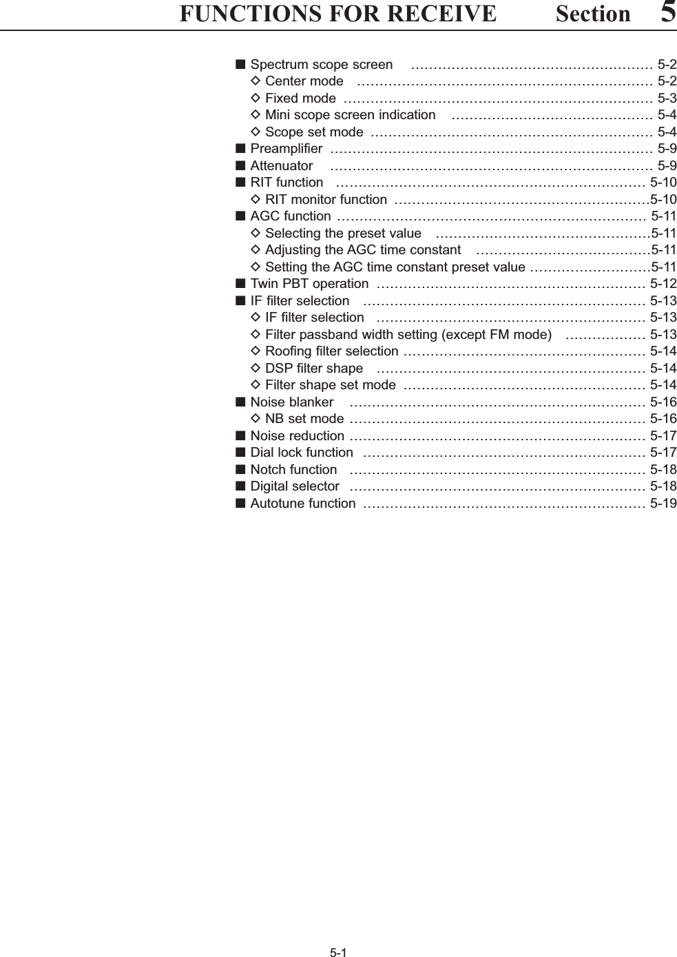
![5-2■Spectrum scope screenThis DSP-based spectrum scope allows you to displaythe conditions on the selected band, as well as relativestrengths of signals. The IC-7700 has two modes forthe spectrum indication— one is center mode, and an-ther one is fixed mode. In addition, the IC-7700 has a mini scope screen tosave screen space.DCenter modeDisplays signals around the set frequency within theselected span. The set frequency is always displayedat the center of the screen.qPush several times to close a multi-func-tion screen, if necessary.wPush [SCOPE] to select the scope screen.ePush [CENT/FIX] to select the center mode.• “ ” is displayed when center mode is selected.rPush [SPAN] several times to select thescope span.• ±2.5, ±5.0, ±10, ±25, ±50, ±100 and ±250 kHz are avail-able.• Push and hold [F-1•SPAN] for 1 sec. to return to ±2.5kHz span.• Sweeping speed is selectable for each span indepen-dently in scope set mode. (pgs. 5-5, 5-6)tPush [ATT] several times to activate an atten-uator or turn the attenuator OFF.• 10, 20 and 30 dB attenuators are available.• Push and hold [ATT] for 1 sec. to turn OFF the at-tenuator.yPush [MARKER] to turn the marker for trans-mit frequency ON or OFF.• “ ” displays the marker at the transmit frequency.• “<<” or “>>” appears when the marker is out of range.• The spectrum scope shows the transmit signal wave-form while transmitting. This can be deactivated inscope set mode. (p. 5-5)• The spectrum scope shows the peak level holding func-tion. Peak levels are displayed in the background of thecurrent spectrum in a different color until the receive fre-quency changes. This can be deactivated and the wave-form color can be set in scope set mode. (p. 5-5)uPush [HOLD] to freeze the current spectrumwaveform.• “ ” appears while the function is in use.• The peak hold function can be deactivated in scope setmode.iPush to exit the scope screen.NOTE: If a strong signal is received, a ghost wave-form may appear. Push [ATT] several times toactivate the spectrum scope attenuator in this case.Spurious signal waveforms may be displayed. Theyare generated in the internal scope circuit and donot indicate a transceiver malfunction.F-2EXIT/SETHOLDF-4TF-3F-2F-2F-1CENTERF-5F-1EXIT/SETF-2ATTF-4HOLDF-1SPANF-3MARKERF-5CENT/FIXEXIT/SET5FUNCTIONS FOR RECEIVE• Observed indication example](https://usermanual.wiki/ICOM-orporated/300900.User-Manual-Part-1/User-Guide-900712-Page-91.png)
![5-3DFixed modeDisplays signals within the specified frequency range.The selected frequency band conditions can be ob-served at a glance when using this mode.qPush several times to close a multi-func-tion screen, if necessary.wPush [SCOPE] to select the scope screen.ePush [CENT/FIX] to select the fixed mode.• “ ” is displayed when fixed mode is selected.rPush [ATT] several times to activate an atten-uator or turn the attenuator OFF.• 10, 20 and 30 dB attenuators are available.• Push and hold [ATT] for 1 sec. to turn OFF the at-tenuator.tPush [MARKER] several times to select themarker for transmit frequency or turn the markerOFF.• “ ” displays the marker at the receive frequency. (al-ways displayed)• “ ” displays the marker at the transmit frequency.• “<<” or “>>” appears when the marker is out of range.• The spectrum scope shows the transmit signal wave-form while transmitting. This can be deactivated inscope set mode. (p. 5-5)• The spectrum scope shows the peak level holding func-tion. Peak levels are displayed in the background of thecurrent spectrum in a different color until the receive fre-quency changes. This can be deactivated and the wave-form color can be set in scope set mode. (p. 5-5)yPush [HOLD] to freeze the current spectrumwaveform.• “ ” appears while the function is in use.• The peak hold function can be deactivated in scope setmode.uPush to exit the scope screen.NOTE: If a strong signal is received, a ghost wave-form may appear. Push [ATT] several times toactivate the spectrum scope attenuator in this case.The scope bandwidth can be specified for each op-erating frequency band independently in scope setmode. (pgs. 5-6 to 5-8)F-2EXIT/SETHOLDF-4TRF-3F-2F-2FIXF-5F-1EXIT/SETF-4HOLDF-5CENT/FIXEXIT/SETF-2ATTF-3MARKER5FUNCTIONS FOR RECEIVE](https://usermanual.wiki/ICOM-orporated/300900.User-Manual-Part-1/User-Guide-900712-Page-92.png)
![5-4DMini scope screen indicationThe mini scope screen can be displayed with anotherscreen display, such as set mode menu, decodescreen, memory list screen, etc. simultaneously.qSet the scope mode (center or fixed), marker, at-tenuator, span, etc. in advance. (pgs. 5-2, 5-3)wPush to toggle the mini scope indicationON and OFF.• The S/RF meter type during mini scope indication canbe selected in display set mode (Meter Type (WideScreen) item). (p. 12-10)DScope set modeThis set mode is used to set the waveform color,sweeping speed, scope range for fixed mode, etc.qDuring spectrum scope display ON, push [SET] to select scope set mode screen.• Push [WIDE] to toggle the screen size betweennormal and wide.wPush [Y] or [Z] to select the desired setitem.eSet the desired condition using the main dial.• Push and hold [DEF] for 1 sec. to select the de-fault condition or value.• Push [Ω≈] to select the set contents for someitems.rPush to exit from set mode.EXIT/SETF-3F-4F-2F-1F-7F-7M.SCOPEF-3 F-7WIDEΩ ≈Main dialEXIT/SETDEFF-1∫F-2√F-4M.SCOPE5FUNCTIONS FOR RECEIVE](https://usermanual.wiki/ICOM-orporated/300900.User-Manual-Part-1/User-Guide-900712-Page-93.png)
![5-5DScope set mode (continued)5FUNCTIONS FOR RECEIVETurn the transmitting signal waveform indication ONand OFF. NOTE: The transmitting signal waveform indica-tion is available for the center mode only.Scope during Tx (CENTER Type)ONTurn the peak level holding function ON and OFF. Max HoldONSelect the center frequency of the spectrum scopeindication (center mode only).• Filter center : Shows the selected filter’s centerfrequency at the center.• Carrier Point Center: Shows the selected operatingmode carrier point frequency atthe center.• Carrier Point Center (Abs. Freq.): In addition to the carrier pointcenter setting above, the actualfrequency is displayed for thebottom of the scope.CENTER Type DisplayFilter CenterSet the waveform color for the currently received sig-nals.• The color is set in RGB format.• Push [Ω≈] to select R (Red), G (Green) and B(Blue), and rotate the ratio from 0 to 255 range.• The set color is indicated in the box beside the RGBscale.F-3Waveform Color (Current)0204 102Set the waveform color for the receiving signals max-imum level.• The color is set in RGB format.• Push [Ω≈] to select R (Red), G (Green) and B(Blue), and rotate the ratio from 0 to 255 range.• The set color is indicated in the box beside the RGBscale.F-3Waveform Color (Max Hold)0102 153Select the sweep speed for the ±2.5 kHz span selec-tion from SLOW, MID and FAST.NOTE: The waveform may be displayed incorrect-ly with “FAST” setting.Sweep Speed (± 2.5k)MIDSelect the sweep speed for the ±5 kHz span selec-tion from SLOW, MID and FAST.NOTE: The waveform may be displayed incorrect-ly with “FAST” setting.(± 5k)MIDSelect the sweep speed for the ±10 kHz span selec-tion from SLOW, MID and FAST.(± 10k)FAST](https://usermanual.wiki/ICOM-orporated/300900.User-Manual-Part-1/User-Guide-900712-Page-94.png)
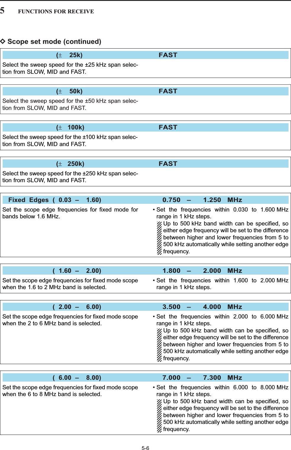
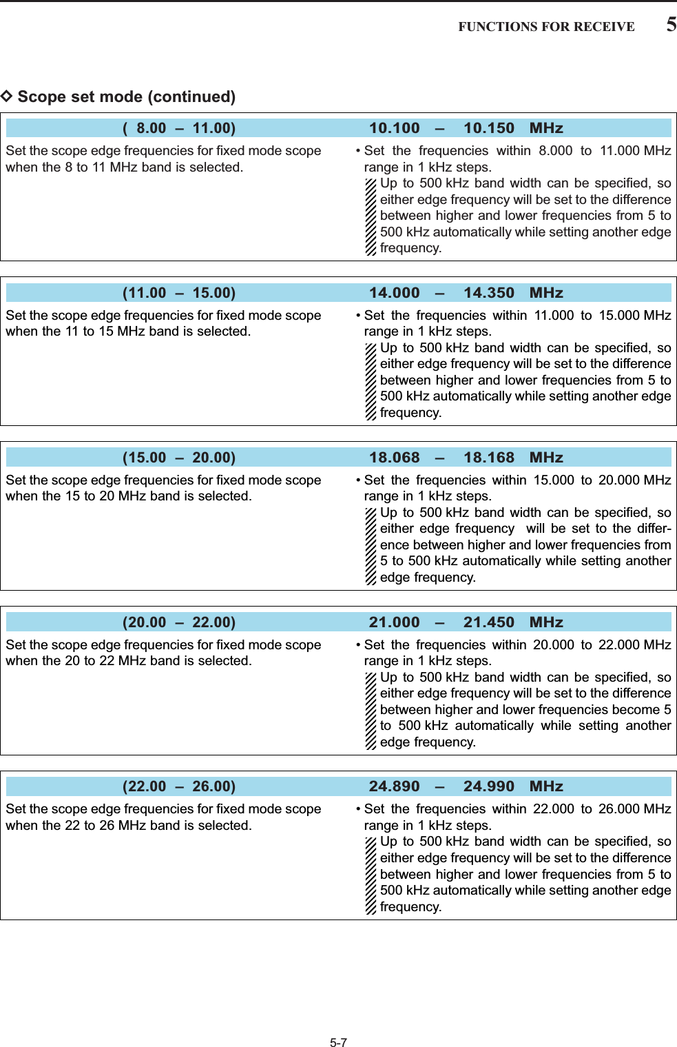

![5-9■PreamplifierThe preamp amplifies received signals in the receiverfront end, to improve the S/N ratio and sensitivity. Setthis to preamp 1 or preamp 2 when receiving weak sig-nals.➥Push [P.AMP] (MF3) several times to set the preampOFF, preamp 1 ON or preamp 2 ON.For all HF bandsHigh-gain preamp for 24 MHz band andabove✔About the “P.AMP2”The “P.AMP 2” is a high gain receive amplifier. Whenthe “P.AMP 2” is used in the presence of strong elec-tromagnetic fields, distortion sometimes results. Insuch cases, use the transceiver with the “P.AMP 1” or“P.AMP OFF” setting.The “P.AMP 2” is most effective when:• Used on bands above 24 MHz and when signals areweak.• Receive sensitivity is insufficient when using low-gainantennas, or while using a narrow band antenna(such as small loop, a Beverage antenna or a shortYagi antenna). ■AttenuatorThe attenuator prevents a desired signal from distor-tion when very strong signals are near the desired fre-quency or when very strong electromagnetic fields,such as from broadcasting stations near your location.➥Push [ATT] (MF4) several times to set the attenuator6 dB, 12 dB, 18 dB or attenuator OFF.➥Push and hold [ATT] (MF4) for 1 sec. to turn the at-tenuator function OFF.P.AMP2P.AMP1P.AMPATT5FUNCTIONS FOR RECEIVE6dBattenuation12 dBattenuation18 dBattenuationATT18dBATT12dBATT6dB](https://usermanual.wiki/ICOM-orporated/300900.User-Manual-Part-1/User-Guide-900712-Page-98.png)
![5-10■RIT functionThe RIT (Receive Increment Tuning) function com-pensates for off-frequency operation of the receivedstation.The function shifts the receive frequency up to±9.99 kHz in 10 Hz steps without moving the transmitfrequency.qPush to turn the RIT function ON and OFF.• “ ” and the shifting frequency appear when the func-tion is ON.wRotate the [RIT/∂TX] control.• Push and hold for 1 sec. to reset the RIT fre-quency.• Push momentarily to reset the RIT frequencywhen the quick RIT/∂TX clear function is ON. (p. 12-15)• Push and hold for 1 sec. to add the shift fre-quency to the operating frequency.DRIT monitor functionWhen the RIT function is ON, pushing and holding[XFC] allows you to monitor the operating frequencydirectly (RIT is temporarily cancelled).✔For your convenience— Calculate functionThe shift frequency of the RIT function can beadded/subtracted to the displayed frequency.➥While displaying the RIT shift frequency, push andhold for 1 sec.RITRITCLEARCLEARRITRIT[RIT/∂TX]RIT CLEARXFC5FUNCTIONS FOR RECEIVE](https://usermanual.wiki/ICOM-orporated/300900.User-Manual-Part-1/User-Guide-900712-Page-99.png)
![5-11■AGC functionThe AGC (auto gain control) controls receiver gain toproduce a constant audio output level even when thereceived signal strength varies greatly.The transceiver has 3 preset AGC characteristics (timeconstant: fast, mid, slow) for non-FM mode. The FM mode AGC time constant is fixed as ‘FAST’(0.1 sec.) and AGC time constant cannot bechanged.DSelecting the preset valueqSelect any non-FM mode.wPush [AGC] (MF5) several times to select AGC fast,AGC medium (MID) or AGC slow.• Push and hold for 1 sec. to turn the AGCfunction OFF. DAdjusting the AGC time constant qSelect any non-FM mode.wPush , then rotate [AGC] control to adjustthe AGC time constant.• [AGC VR] indicator above the switch lights green.DSetting the AGC time constant preset valueqSelect any non-FM mode.wPush and hold [AGC] (MF5) for 1 sec. to enter AGCset mode.ePush [AGC] (MF5) several times to select FAST timeconstant.rRotate the main dial to set the desired time constantfor ‘AGC FAST.’• AGC time constant can be set between 0.1 to 8.0 sec.(depends on mode) or turned OFF.• Push and hold [DEF] for 1 sec. to select a defaultvalue.tPush [AGC] (MF5) to select medium time constant.yRotate the main dial to set the desired time constantfor ‘AGC MID.’• AGC time constant can be set between 0.1 to 8.0 sec.(depends on mode) or turned OFF.• Push and hold [DEF] for 1 sec. to select a defaultvalue.uPush [AGC] (MF5) to select slow time constant.iRotate the main dial to set the desired time constantfor ‘AGC SLOW.’• AGC time constant can be set between 0.1 to 8.0 sec.(depends on mode) or turned OFF.• Push and hold [DEF] for 1 sec. to select a defaultvalue.oSelect another non-FM mode. Repeat steps eto iif desired.!0 Push to exit the AGC set mode screen.EXIT/SETF-4F-4F-4AGC VRAGC VR[AGC] control AGC VR AGC5FUNCTIONS FOR RECEIVEMode Default Selectable AGC time constant0.3 (FAST) 0.1, 0.2, 0.3, 0.5, 0.8, 1.2, 1.6, 2.0, SSB 2.0 (MID) 2.5, 3.0, 4.0, 5.0, 6.06.0 (SLOW)0.1 (FAST) 0.1, 0.2, 0.3, 0.5, 0.8, 1.2, 1.6, 2.0, CW 0.5 (MID) 2.5, 3.0, 4.0, 5.0, 6.01.2 (SLOW)RTTY 0.1 (FAST) 0.1, 0.2, 0.3, 0.5, 0.8, 1.2, 1.6, 2.0, PSK 0.5 (MID) 2.5, 3.0, 4.0, 5.0, 6.01.2 (SLOW)3.0 (FAST) 0.3, 0.5, 0.8, 1.2, 1.6, 2.0, 2.5, 3.0, AM 5.0 (MID) 4.0, 5.0, 6.0, 7.0, 8.07.0 (SLOW)FM 0.1 (FAST) Fixed• Selectable AGC time constant (unit: sec.)](https://usermanual.wiki/ICOM-orporated/300900.User-Manual-Part-1/User-Guide-900712-Page-100.png)
![5-12■Twin PBT operationPBT (Passband Tuning) electronically narrows the IFpassband width by shifting the IF frequency slightlyoutside of the IF filter passband to reject interference.The IC-7700 uses DSP for the PBT function. Movingboth [TWIN-PBT] controls to the same position shiftsthe IF for both high and low frequencies.➥The LCD shows the passband width and shift fre-quency graphically.• PBT indicator above switch lights when PBTis in use.➥Push and hold for 1 sec. to enter the filterset screen. Current passband width and shift fre-quency is displayed in the filter set screen.➥To set the [TWIN-PBT] controls to the center posi-tions, push and hold for 1 sec.The variable range depends on the passband widthand mode. The edge of the variable range is half of thepassband width, and PBT is adjustable in 25(SSB/CW/RTTY/PSK modes) or 100 Hz (AM mode)steps.• [TWIN-PBT] should normally be set to the center posi-tions (PBT setting is cleared) when there is no interfer-ence.• When PBT is used, the audio tone may be changed.• Not available for FM mode.• While rotating [TWIN-PBT], noise may occur. This comesfrom the DSP unit and does not indicate an equipmentmalfunction.• Filter set screen• PBT operation examplePBT-CLRFILTERPBT-CLR[TWIN-PBT]PBT-CLRShows filter width, shifting value and conditionIF center frequency Interference Desired signalPassbandBoth controls at center positionCutting a lower passbandCutting both higher and lower passbandsInterference InterferenceDesired signalPassbandPBT1PBT2PBT1PBT2PBT1PBT25FUNCTIONS FOR RECEIVE](https://usermanual.wiki/ICOM-orporated/300900.User-Manual-Part-1/User-Guide-900712-Page-101.png)
![5-13■IF filter selectionThe transceiver has 3 passband width IF filters foreach mode. For SSB, CW and PSK modes, the passband widthcan be set within 50 to 3600 Hz in 50 or 100 Hz steps.A total of 41 passband widths are available. For RTTY mode, the passband width can be set within50 to 2700 Hz in 50 or 100 Hz steps. A total of 32 pass-band widths are available.For AM mode, the passband width can be set within200 Hz to 10 kHz in 200 Hz steps. A total of 50 pass-band widths are available.For FM mode, the passband width is fixed and 3 pass-band widths are available.The filter selection is automatically memorized ineach mode.The PBT shift frequencies are automatically memo-rized in each filter.DIF filter selectionqSelect the desired mode.wPush several times to select the IF filter1, 2 or 3.• The selected passband width and filter number is dis-played in the LCD.DFilter passband width setting (except FM mode)qPush and hold for 1 sec. to enter filter setscreen.wSelect any mode except FM.• Passband widths for FM modes are fixed and cannot be set.ePush several times to select the desiredIF filter.rWhile pushing [BW] , rotate the main dial to setthe desired passband width.• In SSB, CW and PSK modes, the passband width canbe set within the following range.50 to 500 Hz 50 Hz steps600 to 3600 Hz 100 Hz steps• In RTTY mode, the passband width can be set within thefollowing range.50 to 500 Hz 50 Hz steps600 to 2700 Hz 100 Hz steps• In AM mode, the passband width can be set within thefollowing range.200 Hz to 10 kHz 200 Hz steps• Push and hold [DEF] for 1 sec. to select the defaultvalue.tRepeat steps wto rif desired for other modes.yPush to exit filter set screen.The PBT shift frequencies are cleared when thepassband width is changed.This filter set screen graphically displays the PBTshift frequencies and CW pitch operations.EXIT/SETF-4F-1FILTERFILTERFILTERFILTER5FUNCTIONS FOR RECEIVE](https://usermanual.wiki/ICOM-orporated/300900.User-Manual-Part-1/User-Guide-900712-Page-102.png)
![5-14DRoofing filter selectionThe IC-7700 has 3, 6 and 15 kHz roofing filters at the1st IF frequency. The roofing filter provides interfer-ence reduction from nearby strong signals.qPush and hold for 1 sec. to enter filter setscreen.wSelect any mode except FM.ePush [ROOFING] to select the desired filterwidth from 15 kHz (default), 6 kHz and 3 kHz.• Push and hold [DEF] for 1 sec. to select a defaultvalue.rPush to exit filter set screen.DDSP filter shape The type of DSP filter shape for each SSB, SSB dataand CW can be selected independently from soft andsharp.qPush and hold for 1 sec. to enter filter setscreen.wSelect SSB, SSB data or CW mode.ePush [SHAPE] to select the desired filtershape from soft and sharp.rPush to exit filter set screen.The filter shape can be set for each band (HF and50 MHz bands), mode, as well as the passband widthsetting (CW only) independently from your default set-ting in filter shape set mode.DFilter shape set modeThe type of DSP filter shape for SSB, SSB data andCW can be selected independently from soft andsharp.qPush and hold for 1 sec. to enter filter setscreen.wPush and hold [SHAPE] for 1 sec. to enter fil-ter shape set mode.ePush [Y] or [Z] to select the desired item.rRotate the main dial to select the filter shape fromsoft and sharp.tPush to exit filter shape set mode.EXIT/SETF-2F-1F-7FILTEREXIT/SETF-7FILTEREXIT/SETF-4F-6FILTER5FUNCTIONS FOR RECEIVESelect the filter shape for SSB mode in HF bands. The set filter shape is automatically used onlywhen the IF filter is set to 600 Hz or wider.HF SSB (600Hz – )SHARPSelect the filter shape for SSB data mode in HFbands.The set filter shape is automatically used onlywhen the IF filter is set to 600 Hz or wider.SSB–D (600Hz – )SHARP](https://usermanual.wiki/ICOM-orporated/300900.User-Manual-Part-1/User-Guide-900712-Page-103.png)
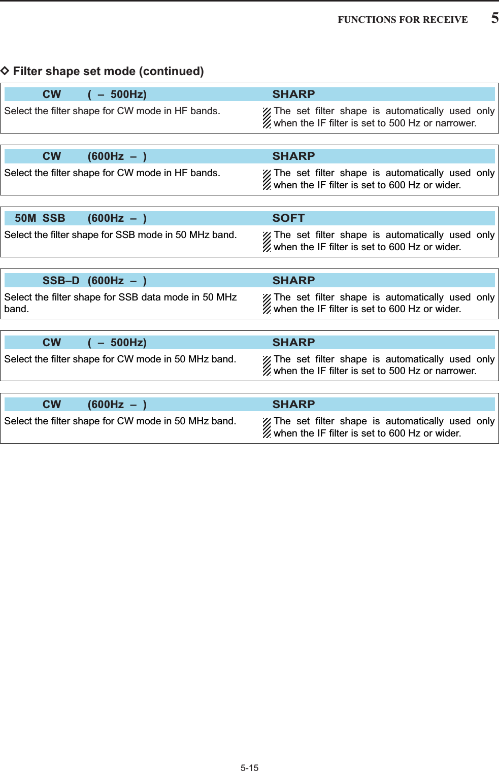
![■Noise blankerThe noise blanker eliminates pulse-type noise such asthe noise from car ignitions. The noise blanker is notavailable for FM mode.qPush to turn the noise blanker function ONand OFF.• [NB] indicator above this switch lights green.wRotate [NB] control to adjust the noise blankerthreshold level.When using the noise blanker, received signals maybe distorted if they are excessively strong or thenoise type is other than impulse. Turn the noiseblanker OFF, or rotate [NB] control to a shallow po-sition in this case.DNB set modeTo deal with various type of noises, attenuation leveland noise blank time can be set in NB set mode.qPush and hold for 1 sec. to enter NB setmode.wPush [Y] or [Z] to select the desired item.eRotate the main dial to set the desired level or value. • Push and hold [DEF] for 1 sec. to select a defaultvalue.rPush to exit NB set mode.EXIT/SETF-4F-2F-1NBNB[NB] controlNB5-165FUNCTIONS FOR RECEIVESet the noise attenuation level from 1 to 10.NB Depth8Set the blank time from 1 to 100.NB Width50](https://usermanual.wiki/ICOM-orporated/300900.User-Manual-Part-1/User-Guide-900712-Page-105.png)
![5-175FUNCTIONS FOR RECEIVE■Noise reductionThe noise reduction function reduces random noisecomponents and enhances desired signals which areburied in noise. The DSP performs the random noisereduction function.qPush to turn the noise reduction ON.• [NR] indicator above this switch lights green.wRotate the [NR] control to adjust the noise reductionlevel.ePush to turn the noise reduction OFF.• [NR] indicator lights off.Large rotations of the [NR] control results in audiosignal masking or distortion. Set the [NR] control formaximum readability.■Dial lock functionThe dial lock function prevents frequency changes byaccidental movement of the tuning dial. The lock func-tion electronically locks the dial.➥Push [LOCK] to toggle the dial lock function ON andOFF.• The [LOCK] indicator lights when the dial lock functionis in use.NRNR[LOCK] indicator LOCK[NR] controlNR](https://usermanual.wiki/ICOM-orporated/300900.User-Manual-Part-1/User-Guide-900712-Page-106.png)
![■Notch functionThis transceiver has auto and manual notch functions. The auto notch function uses DSP to automatically at-tenuate more than 3 beat tones, tuning signals, etc.,even if they are moving. The manual notch can be setto attenuate a frequency via the [NOTCH] control.Theauto notch can be used in SSB, AM and FM mode.The manual notch can be used in SSB, CW, RTTY,PSK and AM modes.➥Push to toggle the notch function betweenauto, manual and OFF in SSB and AM modes.➥Push to turn the manual notch functionON and OFF in CW, RTTY, PSK modes.➥Push to turn the auto notch function ONand OFF in FM mode.• [NOTCH] indicator above this switch lights green.• Push and hold for 1 sec. to select the notch fil-ter width for manual notch from wide, middle and nar-row.• Set to attenuate a frequency for manual notch via the[NOTCH] control.• “ ” appears when auto notch is in use.• “ ” appears when manual notch is in use.While tuning the manual notch, noise may be heard.This comes from the DSP unit and does not indicatean equipment malfunction.■Digital selectorThe digital selector manually adjusts the center fre-quency of the automatic pre-selector.The automatic pre-selector adds selectivity ahead ofthe 1st mixer. This reduces intermodulation distortionfrom the nearby strong signals.The automatic pre-selector tracks the frequency tun-ing, changing it’s resonant frequency in discrete steps.qPush to turn the digital selector ON andOFF.• [DIGI-SEL] indicator above this switch lights green.wRotate [DIGI-SEL] control to adjust the center fre-quency.NOTE:• When rotating the main dial while the digital selec-tor is activated, mechanical noise may be hearddue to the switching noise from internal relays. • The preamp (P.AMP1 or P.AMP2) cannot be usedwhile the digital selector is activated.DIGI-SELMNANNOTCHNOTCHNOTCHNOTCH[NOTCH] controlNOTCH[DIGI-SEL] controlDIGI-SEL5-185FUNCTIONS FOR RECEIVE• Manual notch indication• Auto notch indication](https://usermanual.wiki/ICOM-orporated/300900.User-Manual-Part-1/User-Guide-900712-Page-107.png)
![5-195FUNCTIONS FOR RECEIVE■Autotune functionThe Automatic tuning function tunes the displayed fre-quency (max. CW: 500 Hz, AM: ±5 kHz) automaticallywhen an off frequency signal is received. This functionis active while in CW or AM mode is selected.➥Push [AUTOTUNE] to toggle the autotune functionON or OFF.•“”blinks when autotune function is activate.• After 30 sec. has passed, the autotune function stopstuning automatically even it’s still off-frequency.AUTOTUNEAppearsAUTOTUNEAUTOTUNE](https://usermanual.wiki/ICOM-orporated/300900.User-Manual-Part-1/User-Guide-900712-Page-108.png)