ICOM orporated 300900 HF/50 MHz Transceiver User Manual IC 7700 ENG
ICOM Incorporated HF/50 MHz Transceiver IC 7700 ENG
UserManual.wiki
>
ICOM orporated
>
300900 User Manual
>
User Manual Part 2
Contents
1.
User Manual Part 1
2.
User Manual Part 2
User Manual Part 2
Navigation menu
Upload a User Manual
Namespaces
Wiki Guide
HTML
PDF
Info
Views
User Manual
Discussion / Help
Navigation
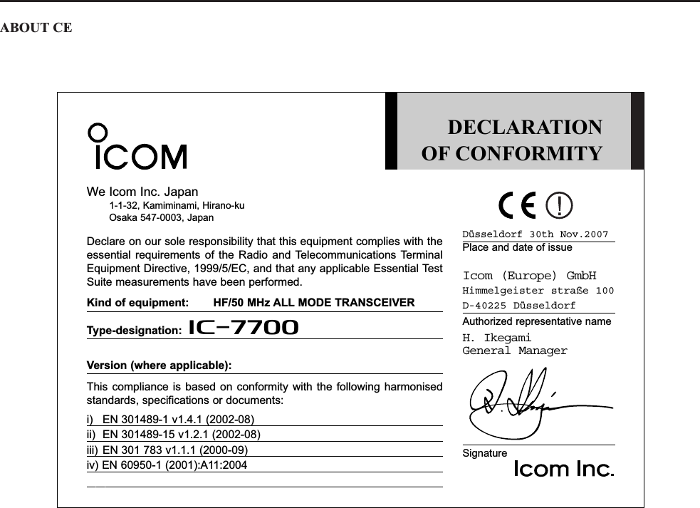
![6-2■VOX functionThe VOX (Voice-Operated Transmission) functionswitches between transmit and receive with your voice.This function provides “hands-free” operation.DUsing the VOX functionqSelect a phone mode (SSB, AM, FM).wPush to turn the VOX function ON or OFF.• “ ” appears while the VOX is in use.• [VOX] indicator above this switch lights green.DAdjusting the VOX functionqSelect a phone mode (SSB, AM, FM).wPush to turn VOX function ON.eWhile speaking into the microphone with your nor-mal voice level, rotate [VOX GAIN] to the pointwhere the transceiver is continuously transmitting.rDuring receive, rotate [ANTI VOX] to the pointwhere the transceiver does not switch to transmitdue to received audio from the speaker.tAdjust the VOX delay and the VOX voice delay inVOX set mode, if necessary.DVOX set modeqPush and hold for 1 sec. to enter VOX setmode.wSelect the desired item using [Y] or [Z] .eRotate the main dial to the desired set value or con-dition.• Push and hold [DEF] for 1 sec. to select a defaultvalue.rPush to exit VOX set mode.EXIT/SETF-4F-2F-1VOXVOXVOXVOX[VOX GAIN] [ANTI VOX]AM/FMSSBVOXAM/FMSSBVOX6FUNCTIONS FOR TRANSMITSet the VOX delay for a convenient interval before re-turning to receive within 0 to 2.0 sec. range.VOX Delay0.2sSet the VOX voice delay to prevent unintended trans-mission of your voice when switching to transmit.Short, Mid., Long and OFF settings are available.When using the VOX voice delay, turn the TX mon-itor function OFF to prevent transmitted audio frombe echoed.VOX Voice DelayShort](https://usermanual.wiki/ICOM-orporated/300900.User-Manual-Part-2/User-Guide-900713-Page-2.png)
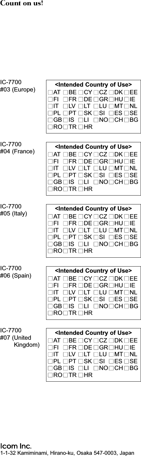
![6-3■Break-in functionThe break-in function is used in CW mode to automat-ically toggle the transceiver between transmit and re-ceive when keying. The IC-7700 is capable of fullbreak-in or semi break-in.DSemi break-in operationDuring semi break-in operation, the transceiver selectstransmit when keying, then automatically returns to re-ceive after a pre-set time after you stop sending.qPush to select CW or CW-R mode.wPush once or twice to turn the semi break-infunction ON.• “ ” appears.eRotate [DELAY] to set the break-in delay time (thedelay from transmit to receive).When using a paddle, rotate [KEY SPEED] to adjustthe keying speed.DFull break-in operationDuring full break-in operation, the transceiver auto-matically enters transmit while keying and returns toreceive immediately after keying is finished.qPush to select CW or CW-R mode.wPush once or twice to turn the full break-infunction ON.• “ ” appears.When using a paddle, rotate [KEY SPEED] to adjustthe keying speed.F-BKINBK-INCWBKINBK-INCWBK-INCW[DELAY] (outer control)[KEY SPEED] (inner control)6FUNCTIONS FOR TRANSMIT](https://usermanual.wiki/ICOM-orporated/300900.User-Manual-Part-2/User-Guide-900713-Page-3.png)
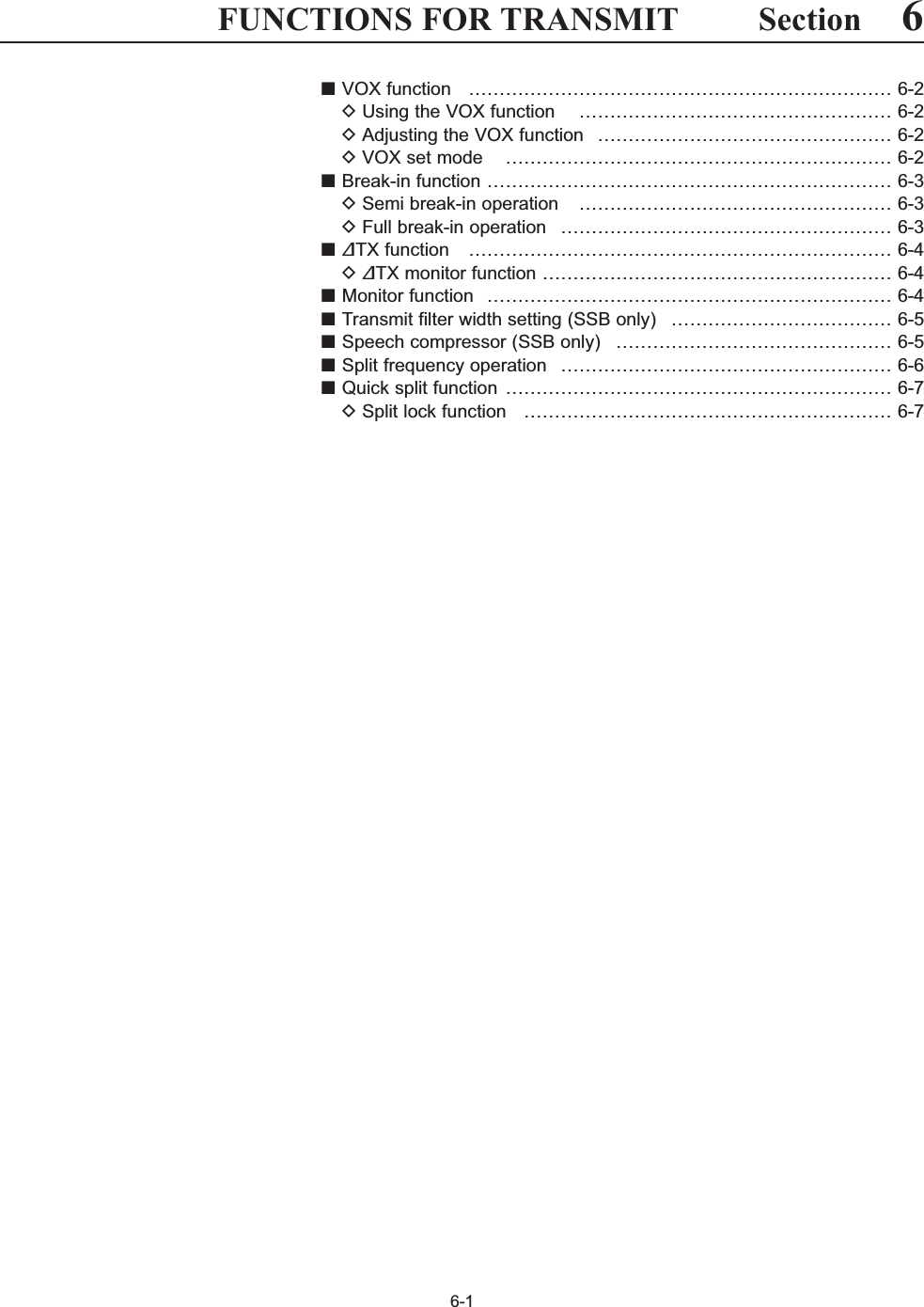
![6-4■∂TX functionThe ∂TX function shifts the transmit frequency up to±9.999 kHz in 1 Hz steps (10 Hz steps when cancellingthe 1 Hz step readout) without moving the receive fre-quency.qPush .• “ ” appears.wRotate [RIT/∂TX].eTo reset the ∂TX frequency, push and holdfor 1 sec.• Push momentarily to reset the ∂TX frequencywhen the quick RIT/∂TX clear function is ON. (p. 12-15)rTo cancel the ∂TX function, push again.• “ ” disappears.D∂TX monitor functionWhen the ∂TX function is ON, pushing and holding[XFC] allows you to monitor the operating frequencydirectly (∂TX is temporarily cancelled).✔For your convenience— Calculate functionThe shift frequency of the ∂TX function can beadded/subtracted to the displayed frequency.➥While displaying the ∂TX shift frequency, push andhold for 1 sec.■Monitor functionThe monitor function allows you to monitor your trans-mit IF signals in any mode. Use this to check voicecharacteristics while adjusting SSB transmit parame-ter (p. 12-5). The CW sidetone functions regardless ofthe switch setting.qPush to switch the monitor function ONand OFF.• [MONITOR] indicator above this switch lights green.wRotate [MONI GAIN] for the clearest audio outputwhile pushing [PTT] and speaking into the micro-phone.NOTE: When using the VOX voice delay, turn themonitor function OFF; or transmitted audio will beechoed.MONITORMONITOR∂TX∂TX∂TXCLEARCLEAR∂TX∂TX[RIT/∂TX]∂TX CLEARXFC[MONI GAIN]MONITOR6FUNCTIONS FOR TRANSMIT](https://usermanual.wiki/ICOM-orporated/300900.User-Manual-Part-2/User-Guide-900713-Page-4.png)
![6-5■Transmit filter width setting (SSB only)The transmit filter width for SSB mode can be selectedfrom wide, middle and narrow.➥During USB or LSB mode selection, push and hold[COMP] (MF6) for 1 sec. several times to select thedesired transmit filter width from wide, middle andnarrow.• The filter can be independently set on the speech com-pressor function is ON and OFF.• The following filters are specified as the default. Each ofthe filter width can be re-set in level set mode. (p. 12-6)WIDE : 100 Hz to 2.9 kHzMID : 300 Hz to 2.7 kHzNAR : 500 Hz to 2.5 kHz■Speech compressor (SSB only)The speech compressor increases average RF outputpower, improving signal strength and readability inSSB mode only.qSelect USB or LSB mode and adjust [MIC] to a suit-able level.• Push [METER] (MF2) several times to select the ALCmeter for microphone gain adjustment.wPush [COMP] (MF6) to turn the speech compressorON.ePush [METER] (MF2) once to select the COMPmeter.rWhile speaking into the microphone, rotate [COMP]control, so that the COMP meter reads within theCOMP zone (10 to 20 dB range) for your normalvoice level.When the COMP meter peaks exceed the COMPzone, your transmitted voice may be distorted.tPush [METER] (MF2) 5 times to select the ALCmeter.yWhile speaking into the microphone, rotate [DRIVE],so that the ALC meter reads within the 30 to 50%range of the ALC zone with your normal voice level.✔For your conveniencePush and hold [METER] (MF2) for 1 sec. to display themulti-function meter that can check the ALC andCOMP level at a glance.S1000125101010 2044 52V50 100 150 200 2501531.5IDVDdBWAPoSWRCOMP ALC59+20 +40 +60dB∞COMP zone[MIC][DRIVE] [COMP] controlCOMPMETERCOMP6FUNCTIONS FOR TRANSMIT](https://usermanual.wiki/ICOM-orporated/300900.User-Manual-Part-2/User-Guide-900713-Page-5.png)
![6-6■Split frequency operationSplit frequency operation allows you to transmit andreceive in the same mode on two different frequencies.Split frequency operation is performed using 2 fre-quencies on the main and sub readouts.The following is an example of setting 21.290 MHz forreceiving and 21.310 MHz for transmitting.qSet 21.290 MHz (USB) in VFO mode.wPush momentarily, then push and holdfor 1 sec.• The quick split function is much more convenient for se-lecting the transmit frequency. See the next section fordetails.• The equalized transmit frequency and “ ” appearon the LCD.• [SPLIT] indicator lights.• “TX” appears to show the transmit frequency readout.eSet the transmit frequency to 21.310 MHz in the fol-lowing way. ➥Rotate the main dial while pushing [XFC].• The transmit frequency can be monitored while push-ing [XFC].rNow you can receive on 21.290 MHz and transmiton 21.310 MHz.To change the transmit and receive frequencies, pushto exchange the main and sub readouts.✔CONVENIENT• Direct shift frequency inputThe shift frequency can be entered directly.qPush .wEnter the desired shift frequency with the digit keys.• 1 kHz to 1 MHz can be set.• When you require a negative shift direction, pushin advance.ePush .• The shift frequency is input in the sub readout and thesplit function is turned ON.[Example]To transmit on 1 kHz higher frequency:- Push , then .To transmit on 3 kHz lower frequency:- Push , , then .• Split lock functionAccidentally releasing [XFC] while rotating the maindial changes the receive frequency. To prevent this,use both the split lock and dial lock functions to changethe transmit frequency only. The split lock function can-cels the dial lock function while pushing [XFC] duringsplit frequency operation. The dial lock’s effect during split frequency operationcan be selected in the set mode for both receive andtransmit frequencies; or only the receive frequency. (p. 12-13)SPLIT73GENE •F-INPENTSPLIT1.8 1F-INPENTSPLITGENE •F-INPENTA/BSPLITA=BSPLITMain dial[SPLIT] indicatorSPLITA/B A=BXFC6FUNCTIONS FOR TRANSMIT• When the split function ON• When [XFC] is pushed• The split frequency operation is ready](https://usermanual.wiki/ICOM-orporated/300900.User-Manual-Part-2/User-Guide-900713-Page-6.png)
![6-7■Quick split functionWhen you find a DX station, an important considera-tion is how to set the split frequency.When you push and hold the switch for 1 sec.,split frequency operation is turned ON and the trans-mit frequency is equalized to the received frequency.This shortens the time needed to begin split frequencyoperation.The quick split function is ON by default. For your con-venience, it can be turned OFF in Others set mode.(p. 12-12) In this case, the switch does notequalize the transmit frequency to the receive fre-quency.qSuppose you are operating at 21.290 MHz (USB) inVFO mode. wPush and hold for 1 sec.• Split frequency operation is turned ON.• The transmit frequency (unselected VFO’s readout) isequalized to the receive frequency (selected VFO’s read-out).• “ ” indicator appears.eEnter the desired offset frequency from the keypadthen push , or set the transmit frequencywith the main dial while pushing [XFC].• “ ” indicator appears when is pushed.• Offset frequency setting with the keypad— exampleTo transmit on 1 kHz higher frequency:- Push , then .To transmit on 3 kHz lower frequency:- Push , , then .DSplit lock functionThe split lock function is convenient for changing onlythe transmit frequency. When the split lock function isnot used, accidentally releasing [XFC] while rotatingthe main dial, changes the receive frequency. The splitlock function is ON by default, but can be turned OFFin set mode. (p. 12-13)qWhile split frequency operation is ON, push [LOCK]to activate the split lock function.wWhile pushing [XFC], rotate the main dial to changethe transmit frequency.• If you accidentally release [XFC] while rotating the maindial, the receive frequency does NOT change.SPLIT73GENE •F-INPENTSPLIT1.8 1F-INPENTF-INPENTF-INPSPLITF-INPSPLITSPLITSPLITMain dial[SPLIT] indicatorSPLITXFCMain dial[LOCK] indicatorXFCLOCK6FUNCTIONS FOR TRANSMIT](https://usermanual.wiki/ICOM-orporated/300900.User-Manual-Part-2/User-Guide-900713-Page-7.png)
![7-2■About digital voice recorderThe IC-7700 has digital voice memories, up to 4 mes-sages for transmit, and up to 20 messages for receive. A maximum message length of 30 sec. can berecorded into receive memory (total message lengthfor all channels of up to 209 sec.) and a total messagelength of up to 99 sec. can be recorded in transmitmemory. The transmit memory is very convenient for repeatedCQ and exchange transmissions in contests, as wellas when making consecutive calls to DXpeditions.qSelect any mode.wPush [VOICE] to display voice recorder screen.ePush to display voice recorder menu.rPush [PLAY] or [MIC REC] to select thedesired memory channel screen, then record audioor playback the contents as described below.tPush twice to exit voice recorder screen.EXIT/SETF-2F-1EXIT/SETF-2EXIT/SETREC PLAYF-1 F-2• Example— When [REC] is pushed and held for 1sec.• Example— When [REC] is pushed momentarily• Playing back the all contents in a channel • Playing back the end of 5 sec.* in a channel20 sec.15 sec.(default)30 sec. (max.) Not playing back Play back (5 sec.; default)3 sec.30 sec.Push momentarily within 30 sec. after pushing and holding for 1 sec., records the all contents.Push momentarily re-cords the contents of the previous 15 sec.*When is pushed momentarily again within 15 sec.* from the last operation, all the contents between operations will be recorded.Push momentarily after passing 30 sec. from pushing and holding for 1 sec., records the 30 sec. before can-celing the record.These contents won’t be recorded.*The recording time period can be changed with “Normal Rec Time” in voice set mode (p. 7-9).*The playing back time period can be changed with “Short Play Time” in voice set mode (p. 7-9).NOTE: The contents will be recorded into an independent memory channels automatically.RECRECRECRECRECRECRECRECPush and hold for 1 sec.(starts recording)RECPush momentarily(starts recording)RECPush momentarily(starts recording)RECPush momentarily(stops recording)RECPush and hold for 1 sec.(starts recording)RECPush momentarily(stops recording)RECPush momentarily.PLAYOr, push and hold for 1 sec.PLAYPush momentarily.F-2PLAY7VOICE RECORDER FUNCTIONS](https://usermanual.wiki/ICOM-orporated/300900.User-Manual-Part-2/User-Guide-900713-Page-10.png)
![7-3■Recording a received audioUp to 20 receive voice memories are available in theIC-7700. A total audio length of up to 209 sec. can berecorded in receive messages. However, the maximumrecordable length into a single message is 30 sec. This voice recorder records not only the receivedaudio, but also the information such as set operatingfrequency, mode, and the recording time for your fu-ture reference.DBasic recordingqPush several times to close a multi-func-tion screen, if necessary.wSelect the desired mode.ePush [VOICE] to call up the voice recorderscreen.• Previously selected screen, TX or RX memory, is dis-played. If the TX memory channel (T1–T4) appears,push [T/R] to select RX memory channel.rPush and hold for 1 sec. to start recording.• The operating frequency, mode and current time are pro-grammed as the memory names automatically.tPush momentarily to stop recording.IMPORTANT!Push to stop recording before, or when30 sec. has passed from the start of recording.The voice recorder memory records the 30 sec.(max.) of audio before is pushed.For example, when recording 40 sec. of audio,the first 10 sec. audio will be over-written with thelast 10 sec., so that the total of audio recorded isonly 30 sec.When you record the 21st audio message, orwhen the total audio length exceeds 209 sec., theoldest recorded audio is automatically erased tomake room for the new audio.yPush twice to exit the voice recorderscreen.NOTE: When transmit (or [PTT] is pushed) whilerecording, no audio will be recorded.DOne-touch recordingTo record the received signal immediately, one-touchvoice recording is available.➥Push momentarily to record the previous15 sec. audio.• The recordable time period can be set in voice set mode.(p. 7-9)RECEXIT/SETRECRECRECRECF-7F-2EXIT/SETEXIT/SETRECF-7T/RF-2VOICEREC7VOICE RECORDER FUNCTIONS](https://usermanual.wiki/ICOM-orporated/300900.User-Manual-Part-2/User-Guide-900713-Page-11.png)
![7-4■Playing the recorded audioDBasic playingqPush several times to close a multi-func-tion screen, if necessary.wPush [VOICE] to call up the voice recorderscreen.• Previously selected screen, TX or RX memory, is dis-played. If the TX memory message (T1–T4) appears,push [T/R] to select RX memory message.ePush [Y] or [Z] to select the desiredvoice memory to playback.rPush [PLAY] to start playback.• “ ” indicators appear and the timer counts down.tPush [PLAY] again to stop playback if desired.• Playback is terminated automatically when all of therecorded contents in the message are played, or after30 sec.yPush twice to exit the voice recorderscreen.DOne-touch playingThe previously recorded audio in message 1 can beplayed back without selecting voice recorder screen.➥Push momentarily to play back the last 5 sec.of the previously recorded audio.• “ ” indicator appears.• Playback is terminated automatically when all of therecorded contents in the message are played, or after5 sec.• The playback time period can be set in voice set mode.(p. 7-9)≈PLAYPLAYEXIT/SETF-3≈PLAYF-3F-2F-1F-7F-2EXIT/SETF-3PLAYF-1∫F-2√AppearsAppearsCounts downPLAY7VOICE RECORDER FUNCTIONS](https://usermanual.wiki/ICOM-orporated/300900.User-Manual-Part-2/User-Guide-900713-Page-12.png)
![7-5■Protect the recorded contentsThe protect function is available to protect the recordedcontents from accidental erasure, such as over-writing,etc.qCall up the voice recorder screen, RX memory.wPush [Y] or [Z] to select the desiredvoice message.ePush [PROTECT] to turn the protect functionON and OFF.• “ ” indicator appears when the contents is protected.rPush twice to exit the voice recorderscreen.■Erasing the recorded contentsThe recorded contents can be erased independentlyby message.qCall up the voice recorder screen, RX memory.wPush [Y] or [Z] to select the desiredvoice message to be erased.ePush and hold [CLR] for 1 sec. to erase thecontents.• Push [PROTECT] to release the protection in ad-vance if necessary.rPush twice to exit the voice recorderscreen.EXIT/SETF-4F-5F-2F-1EXIT/SETF-4F-2F-1F-4PROTECTF-1∫F-2√F-5CLRF-1∫F-2√7VOICE RECORDER FUNCTIONS](https://usermanual.wiki/ICOM-orporated/300900.User-Manual-Part-2/User-Guide-900713-Page-13.png)
![7-6■Recording a message for transmitTo transmit a message using the voice recorder, recordthe desired message in advance as described below.The IC-7700 has digital voice memories for transmis-sion, up to 4 messages and a total message length ofup to 99 sec. can be recorded.DRecordingqPush several times to close a multi-func-tion screen, if necessary.wPush [VOICE] to call up the voice recorderscreen.ePush to select voice recorder menu.rPush [MIC REC] to select the voice mic.record screen.tPush [Y]or[Z] to select the desiredmessage.yPush and hold [REC] for 1 sec. to start record-ing.• “ ” indicator appears.• Speak into the microphone without pushing [PTT].• Previously recorded contents are cleared.• Audio output from the internal speaker is automaticallymuted.uWhile speaking into the microphone with your nor-mal voice level, adjust the [MIC] control so that the[MIC-REC LEVEL] indicator reads within 100%.iPush [REC] momentarily to stop recording.• The recording is terminated automatically when the re-maining time becomes 0 sec.oPush twice to exit the voice recorderscreen.DConfirming a message for transmitqPerform the steps qto ras “DRecording” above.wPush [Y]or[Z] to select the desiredmessage.ePush [PLAY] to playback the recorded con-tents.• “ ” indicator appears.rPush [PLAY] again to stop playback.• Playback is terminated automatically when all of therecorded contents in the message are played.tPush twice to exit the voice recorderscreen.EXIT/SETF-3≈PLAYF-3F-2F-1EXIT/SETF-4●RECF-4F-2F-1F-2EXIT/SETF-2EXIT/SETF-4RECF-1∫F-2√Appears Adjust [MIC] control so that this indicator reads within 100%.F-3PLAYF-1∫F-2√7VOICE RECORDER FUNCTIONS](https://usermanual.wiki/ICOM-orporated/300900.User-Manual-Part-2/User-Guide-900713-Page-14.png)
![7-7■Programming a memory name Memory messages can be tagged with alphanumericnames of up to 20 characters each.Capital letters, small letters, numerals, some symbols(! # $ % & ¥ ? “ ‘ ` ^ + – ✱/ . , : ; = < > ( ) [ ] { } | _ ~@)and spaces can be used. (See the table below.)qRecord a message as described in page 7-6.wDuring the voice mic. record screen indication, push[NAME] to enter memory name edit condition.• A cursor appears and blinks.ePush [T1..T4] several times to select the de-sired voice message.rInput the desired character by rotating the main dialor by pushing the band key for number input.• Push [ABC] (MF6) or [abc] (MF6) to toggle capital andsmall letters.• Push [123] (MF7) or [Symbol] (MF7) to toggle numeralsand symbols.• Push [Ω] or [≈] for cursor movement.• Push [DEL] to delete the selected character.• Push [SPACE] to input a space.• Pushing the transceiver’s keypad, [0]–[9], can also enternumerals.tPush to input and set the name.• The cursor disappears.yRepeat steps eto tto program another voicemessage’s name, if desired.uPush twice to exit the voice recorderscreen.• Voice memory name editing example • Usable charactersEXIT/SETEXIT/SETF-4F-3F-2F-1F-7F-5KeypadT1..T4F-7//F-3DEL123 Symbol ABC abcF-1ΩF-2≈F-4SPACE7VOICE RECORDER FUNCTIONSKey selection Editable charactersA to Z (capital letters)a to z (small letters)0 to 9 (numbers)! # $ % & ¥ ? “ ‘ ` ^ + – ✱/ . , : ; =< > ( ) [ ] { } | _ ~@Symbol123abcABC](https://usermanual.wiki/ICOM-orporated/300900.User-Manual-Part-2/User-Guide-900713-Page-15.png)
![7-8■Sending a recorded messageqPush several times to close a multi-func-tion screen, if necessary.wSelect a phone mode by pushing or .ePush [VOICE] to call up the voice recorderscreen.• If the receive voice message appears, push [T/R] to select TX message (T1–T4).rPush the desired message switch, [T1] to [T4], momentarily to transmit the contents.• The transceiver transmits automatically.• “ ” indicator appears and the memory timercounts down.• You hear the transmitted message from the speaker asthe default. This can be turned OFF in voice set mode.(p. 7-9)tPush the selected message switch, [T1] to[T4] , again to stop, if desired.• The transceiver returns to receive automatically when allof the recorded contents in the message are transmit-ted.yPush twice to exit the voice memoryscreen.✔For your informationWhen an external keypad is connected to [EXT KEY-PAD], the recorded message, T1–T4, can be transmit-ted without opening the voice recorder screen.See page 2-7 for details.DTransmit level settingqCall up the voice recorder screen as described asabove.wPush [TX LEV.] to select the voice memorytransmit level set condition.ePush the desired message switch, [T1] to [T4], momentarily to transmit the contents.• The transceiver transmits automatically.• “ ” indicator appears and the memory timercounts down.rRotate the main dial to adjust the transmit voicelevel.• Push and hold [DEF] for 1 sec. to select the defaultcondition.tPush to return to the voice recorderscreen.EXIT/SETF-7SENDF-4F-1F-6EXIT/SETF-4F-1SENDF-4F-1F-7F-2AM/FMSSBEXIT/SETF-1T1F-2T2F-3T3F-4T4F-7T/REXIT/SETAppears Counts downMain dialEXIT/SETF-6TX LEV.F-7DEF7VOICE RECORDER FUNCTIONS](https://usermanual.wiki/ICOM-orporated/300900.User-Manual-Part-2/User-Guide-900713-Page-16.png)
![7-9■Voice set modeSets the automatic monitor function, short play andnormal recording times for voice recorder.qPush several times to close a multi-func-tion screen, if necessary.wPush [VOICE] to call up the voice recorderscreen.ePush to select voice recorder menu.rPush [SET] to select voice set mode screen.tPush [Y] or [Z] to select the desired item.yRotate the main dial to set the desired condition orvalue.• Push and hold [F-4•DEF] for 1 sec. to select thedefault condition or value.uPush to exit the voice set mode screen.EXIT/SETF-4F-2F-1F-7EXIT/SETF-2EXIT/SETMain dialF-4DEFF-1∫F-2√EXIT/SET7VOICE RECORDER FUNCTIONSTurn the automatic monitor function for recordedaudio contents transmission.• ON : Monitors transmitting audio automaticallywhen sending a recorded audio.• OFF : Monitors transmitting audio only when themonitor function is in use.Auto MonitorONSet the desired time period for the one-touch playing(when is pushed momentarily).• 3 to 10 sec. in 1 sec. steps can be set. (default: 5 sec.)PLAYShort Play Time5sSet the desired time period for the for one-touchrecording (when is pushed momentarily).• 5 to 15 sec. in 1 sec. steps can be set. (default: 15 sec.)RECNormal Rec Time15s](https://usermanual.wiki/ICOM-orporated/300900.User-Manual-Part-2/User-Guide-900713-Page-17.png)
![7-10■Saving a voice message into the USB-MemoryDSaving the received audio memoryThe recorded RX memory contents can be saved intothe USB-Memory.qDuring voice recorder RX memory screen display,push [SAVE] to select voice file save screen.• Previously selected screen, TX or RX memory, is dis-played. If the TX message (T1–T4) appears, push [T/R]to select RX message.wChange the following conditions if desired.• File name:zPush [EDIT] to select file name edit con-dition.• Push [DIR/FILE] several times to select thefile name, if necessary.xPush [ABC] (MF6), [123] (MF7) or [Symbol](MF7) to select the character group, then ro-tate the main dial to select the character.• [ABC] (MF6) : A to Z (capital letters); [123] (MF7): 0to 9 (numerals); [Symbol] (MF7): ! # $ % & ‘ ` ^ + –= ( ) [ ] { } _ ~@ can be selected.• Push [Ω] to move the cursor left, push [≈]to move the cursor right, push [DEL] todelete a character and push [SPACE] to in-sert a space.cPush to set the file name.• Saving locationzPush [DIR/FILE] to select tree viewscreen.xSelect the desired directory or folder in theUSB-Memory.• Push [Ω≈] to select the upper directory.• Push [Y] or [Z] to select folder in thesame directory.• Push and hold [Ω≈] for 1 sec. to select afolder in the directory.• Push [REN/DEL] to rename the folder.• Push and hold [REN/DEL] for 1 sec. todelete the folder.• Push and hold [MAKE] for 1 sec. to makinga new folder. (Edit the name with the same man-ner as the “• File name” above.)cPush [DIR/FILE] twice to select the filename.ePush [SAVE] .• After the saving is completed, return to voice recorderRX memory screen automatically.DSaving the TX memory The TX memory contents can also be saved into theUSB-Memory. However, the contents are saved withthe message list, set mode conditions, etc. at the sametime. See page 12-22 for details.F-6F-1F-6F-5F-5F-4F-3F-2F-4F-1EXIT/SETF-4F-3F-2F-1F-1F-4F-7F-6Main dialDIR/FILE EXIT/SETF-1F-7WIDEF-6SAVEF-4EDIT7VOICE RECORDER FUNCTIONS• Voice recorder RX memory screen• Voice file save screen— file name edit• While savingThe USB-Memory is not supplied by Icom.](https://usermanual.wiki/ICOM-orporated/300900.User-Manual-Part-2/User-Guide-900713-Page-18.png)

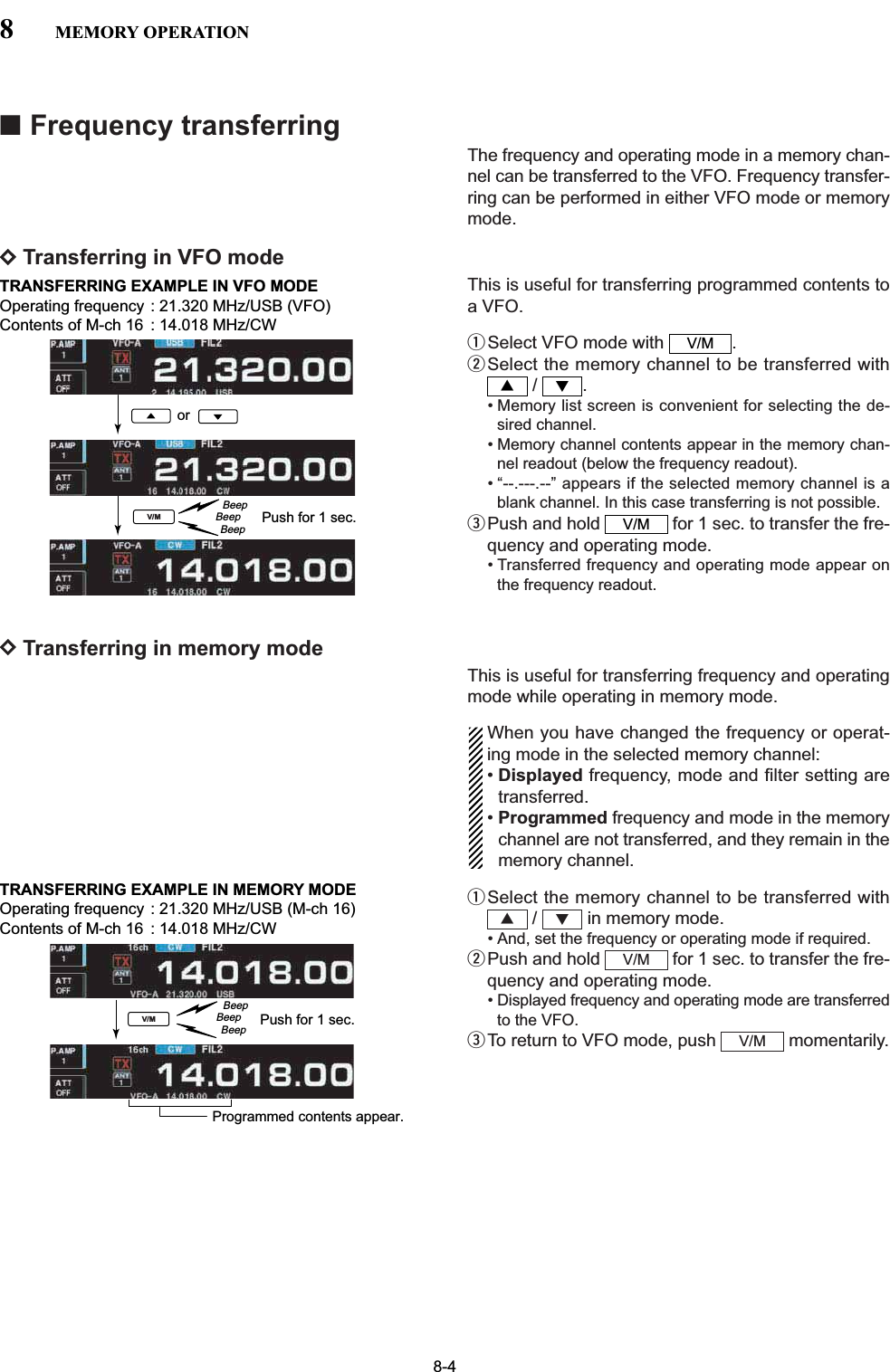
![8-2■Memory channelsThe transceiver has 101 memory channels. Memorymode is very useful for quickly changing to often-usedfrequencies.All 101 memory channels are tunable which means theprogrammed frequency can be tuned temporarily withthe main dial, etc. in memory mode.■Memory channel selectionDUsing the / keysqPush to select memory mode.wPush / several times to select the de-sired memory channel.• Push and hold / for continuous selection.• [UP] and [DN] on the microphone can also be used.eTo return to VFO mode, push again.DUsing the keypadqPush to select memory mode.wPush .ePush the desired memory channel number using thekeypad.• Enter 100 or 101 to select scan edge channel P1 or P2,respectively.rPush or to select the desired memorychannel.[EXAMPLE]To select the memory channel 3;- Push , , then push or .To select the memory channel 12;- Push , , , then push or.To select the scan edge channel P1;- Push , , , , then pushor .To select the scan edge channel P2;- Push , , , , then pushor .√∫1.8 150 01.8 1F-INPENT√∫50 050 01.8 1F-INPENT√∫3.5 21.8 1F-INPENT√∫73F-INPENT√∫F-INPENTV/MV/M√∫√∫V/M√∫V/MY ZKeypad F-IMP ENTV/MY Z8MEMORY OPERATIONMEMORY MEMORY TRANSFER OVER-CHANNEL CHANNEL CAPABILITY TO VFO WRITING CLEARNUMBERRegular memory 1–99 One frequency and one mode Yes Yes Yeschannels in each memory channel.Scan edgeOne frequency and one mode inmemory P1, P2 each memory channel as scan Yes Yes Nochannels edges for programmed scan.](https://usermanual.wiki/ICOM-orporated/300900.User-Manual-Part-2/User-Guide-900713-Page-20.png)
![8-38MEMORY OPERATION■Memory channel programmingMemory channel programming can be preformed ei-ther in VFO mode or in memory mode.DProgramming in VFO modeqSet the desired frequency, operating mode and fil-ter width in VFO mode.wPush / several times to select the de-sired memory channel.• Memory list screen is convenient for selecting the de-sired channel.• Memory channel contents appear in the memory chan-nel readout (below the frequency readout).• “--.---.--” appears if the selected memory channel is ablank channel (and does not have contents).ePush and hold for 1 sec. to program thedisplayed frequency, operating mode, etc., into thememory channel.DProgramming in memory modeqSelect the desired memory channel with /in memory mode.• Memory channel contents appear in the memory chan-nel readout (below the frequency readout).• “--.---.--” appears if the selected memory channel is ablank channel (and does not have contents).wSet the desired frequency and operating mode inmemory mode.• To program a blank channel, use direct frequency entrywith the keypad or memo pads, etc.ePush and hold for 1 sec. to program thedisplayed frequency and operating mode into thememory channel.MW√∫MW√∫MWY ZorPush for 1 sec.BeepBeepBeepMWSSB[EXAMPLE]:Programming 7.088 MHz/LSB into memory channel 12.or thenPush for 1 sec.BeepBeepBeep721MWSSB[EXAMPLE]:Programming 21.280 MHz/USB into memory channel 18.](https://usermanual.wiki/ICOM-orporated/300900.User-Manual-Part-2/User-Guide-900713-Page-21.png)
![8-58MEMORY OPERATION■Memory list screenThe memory list screen simultaneously shows 9 mem-ory channels and their programmed contents. 15 mem-ory channels can be displayed in the wide memory listscreen.You can select a desired memory channel from thememory list screen.DSelecting a memory channel using the memory list screenqPush several times to close a multi-func-tion screen, if necessary.wPush [MEMORY] to select memory list screen.• [WIDE] switches the standard and wide screens.eWhile pushing and holding [ROLL] , rotate themain dial to select the desired memory channel.• and can also be used.rPush to exit memory list screen.• Memory list screenDConfirming programmed memory channelsqSelect memory list screen as described above.wWhile pushing [ROLL] , rotate the main dial toscroll the screen.ePush [SET] to select the highlighted memorychannel, if desired.•“≈” appears beside the selected memory channel num-ber in the memory list screen and the selected memorychannel contents are displayed below the frequencyreadout.rPush to exit memory list screen.EXIT/SETF-2F-1EXIT/SET√∫F-1F-7F-4EXIT/SETMain dialF-2SETF-1ROLL EXIT/SETMain dialZ YF-7WIDEF-1ROLLF-4MEMORY EXIT/SET](https://usermanual.wiki/ICOM-orporated/300900.User-Manual-Part-2/User-Guide-900713-Page-23.png)
![8-68MEMORY OPERATION■Memory namesAll memory channels (including scan edges) can betagged with alphanumeric names of up to 10 charac-ters each.Capital letters, small letters, numerals, some symbols(! # $ % & ¥ ? " ’ ` ^ + – ✱/ . , : ; = < > ( ) [ ] { } | _ ~@)and spaces can be used.DEditing (programming) memory namesqPush several times to close a multi-func-tion screen, if necessary.wPush [MEMORY] to select memory list screen.eSelect the desired memory channel.rPush [NAME] to edit memory channel name.• A cursor appears and blinks.• Memory channel names of blank channels cannot beedited.tInput the desired character by rotating the main dialor by pushing the keypad for number input.• Push [ABC] or [abc] to toggle capital and small letters.• Push [123] or [Symbol] to toggle numerals and symbols.• Push [Ω] or [≈] for cursor movement.• Push [DEL] to delete the selected character.• Push [SPACE] to input a space.• Pushing the transceiver’s keypad, [0]–[9], can also enternumerals.yPush to input and set the name.• The cursor disappears.uRepeat steps eto yto program another memorychannel’s name, if desired.iPush to exit memory list screen.■Memory clearingAny unused memory channels can be cleared. Thecleared memory channels become blank channels.qSelect memory mode with .wPush [MEMORY] to select memory list screen.eSelect the desired memory channel with / .rPush and hold [CLR] for 1 sec. to clear thecontents.• The programmed frequency and operating mode disap-pear.tTo clear other memory channels, repeat steps eand r.F-5√∫F-4V/MEXIT/SETEXIT/SETF-4F-3F-2F-1F-4F-4EXIT/SETPush for 1 sec.BeepBeepBeep(CLR)F-5F-5CLRKeypad//F-3DEL123 Symbol ABC abcF-1ΩF-2≈F-4SPACE](https://usermanual.wiki/ICOM-orporated/300900.User-Manual-Part-2/User-Guide-900713-Page-24.png)
![9-2■Scan types• The scan function can be used on the main read-out only.• You can operate a scan while operating on a fre-quency using the split functions. PROGRAMMED SCANRepeatedly scans between two scan edge frequencies (scan edge memory channels P1 and P2).This scan operates in VFO mode.SELECT MEMORY SCANRepeatedly scans all or one of 3 select memory channels.∂F SCANRepeatedly scans within ∂F span area. This scan operates in memory mode.This scan operates in memory mode.This scan operates in both VFO and memory modes.ScanScan edge P1 or P2Scan edge P2 or P1JumpMEMORY SCANRepeatedly scans all programmed memory channels.Mch 1★1Mch 5★1Mch 2★2Mch 3★1Mch 4Mch 6★3Mch 7★1Mch 99★1Mch 1★1Mch 5★1Mch 2★2Mch 3★1Mch 4Mch 6★3Mch 7★1Mch 99★1Blank channel Blank channelScanScan–∂F frequency +∂F frequencyStart frequencyJump*“★1,” “★2” and “★3” show that the channel is specified as the select memory.*“★1,” “★2” and “★3” show that the channel is specified as the select memory.9SCANS■Preparation• ChannelsFor programmed scan: Program scan edge frequencies into scan edge mem-ory channels P1 and P2.For∂F scan:Set the ∂F span (∂F scan range) in the scan screen.For memory scan: Program 2 or more memory channels except scanedge memory channels.For select memory scan: Designate 2 or more memory channels as select mem-ory channels. To designate the channel as a selectmemory channel, choose a memory channel, thenpush [SELECT] in the scan screen (memorymode) or in the memory list screen.• Scan resume ON/OFFYou can select the scan to resume or cancel when de-tecting a signal in set mode. Scan resume ON/OFFmust be set before operating a scan. See p. 9-3 forON/OFF setting and scan resume condition details.• Scan speedScan speed can be selected from 2 levels, high or low,in scan set mode. See p. 9-3 for details.• Squelch conditionF-3SQUELCHCLOSEDSQUELCHOPENScan stops when detecting a signal.If you set scan resume ON in set mode, thescan pauses for 10 sec. when detecting asignal, then resumes. When a signal disap-pears while scan is paused, scan resumes2 sec. later.The scan continuesuntil it is stoppedmanually, and doesnot pause even if itdetects signals.Scan pauses oneach channel whenthe scan resume isON; not applicablewhen OFF.SCAN PROGRAMMEDSTARTS SCAN MEMORY SCANWITH](https://usermanual.wiki/ICOM-orporated/300900.User-Manual-Part-2/User-Guide-900713-Page-28.png)
![9-3■Voice squelch control functionThis function is useful when you don’t want unmodu-lated signals pausing or cancelling a scan. When thevoice squelch control function is activated, the trans-ceiver checks received signals for voice components.If a received signal includes voice components, andthe tone of the voice components changes within1 sec., scan pauses (or stops). If the received signalincludes no voice components or the tone of the voicecomponents does not change within 1 sec., scan re-sumes.➥While a phone mode (SSB, AM or FM) is selected,push [VSC] (MF7) to switch the VSC (Voice SquelchControl) function ON and OFF.• “VSC” appears when the function is activated.• The VSC function activates for any scan.• The VSC function resumes the scan on unmodu-lated signals, regardless of whether the scan re-sume condition is set to ON or OFF.■Scan set modeWhen the squelch is open, scan continues until it isstopped manually— it does not pause on detected sig-nals. When squelch is closed, scan stops when de-tecting a signal, then resumes according to the scanresume condition. Scan speed and the scan resumecondition can be set using the scan set mode.qPush [SCAN] to select scan screen.wPush [SET] to select scan set mode.ePush [Y] or [Z] to select the desired item.rRotate the main dial to select the desired condition.• Push and hold [DEF] for 1 sec. to select the defaultsetting.tPush to return to scan menu.EXIT/SETF-4F-2F-1F-7F-5Main dialF-4DEFF-1∫F-2√EXIT/SETVSC9SCANSSelect the desired scan speed from high and low. • HIGH : scan is faster• LOW : scan is slowerScan SpeedHIGHSet the scan resume function ON and OFF. • ON : When detecting a signal, scan pauses for10 sec., then resumes. When a signal disap-pears, scan resumes 2 sec. later.• OFF : When detecting a signal, cancels scanning.Scan ResumeON](https://usermanual.wiki/ICOM-orporated/300900.User-Manual-Part-2/User-Guide-900713-Page-29.png)
![9-4■Programmed scan operationqPush several times to close a multi-func-tion screen, if necessary.wSelect VFO mode.eSelect the desired operating mode.• The operating mode can also be changed while scan-ning.rPush [SCAN] to select the scan screen.tSet [SQL] open or closed.• See page 9-2 for squelch condition.yPush [PROG] to start the programmed scan.• “ ” and decimal points blink whilescanning.uWhen the scan detects a signal, scan stops, pausesor ignores it depending on the resume setting andthe squelch condition.iTo cancel the scan, push [PROG] .• Rotating the main dial also cancels the scan.oPush and hold [RECALL] for 1 sec. to recallthe frequency that is set before starting the scan, ifdesired.If the same frequencies are programmed into thescan edge memory channel P1 and P2, pro-grammed scan will not start.■∂F scan operationqPush several times to close a multi-func-tion screen, if necessary.wSelect VFO mode or a memory channel.eSelect the desired operating mode.• The operating mode can also be changed while scan-ning.rPush [SCAN] to select the scan screen.tSet the main band’s [SQL] open or closed.• See page 9-2 for squelch condition.ySet the ∂F span by pushing [∂F SPAN] .• ±5 kHz, ±10 kHz, ±20 kHz, ±50 kHz, ±100 kHz,±500 kHz and ±1000 kHz are selectable.uSet center frequency of the ∂F span.iPush [∂F] to start the ∂F scan.• “ ” and decimal points blink while scanning.oWhen the scan detects a signal, the scan stops,pauses or ignores it depending on the resume set-ting and the squelch condition.!0 To cancel the scan, push [∂F] .• Rotating the main dial also cancels the scan.!1 Push and hold [RECALL] for 1 sec. to recallthe frequency that was set before starting the scan.F-6F-2:F SCANF-2F-4F-5EXIT/SETF-6F-1PROGRAM SCANF-1F-5EXIT/SET[SQL] Main dialEXIT/SETF-1PROG[SQL] Main dialF-2∂FF-4∂F SCAN EXIT/SET9SCANS](https://usermanual.wiki/ICOM-orporated/300900.User-Manual-Part-2/User-Guide-900713-Page-30.png)
![9-5■Fine programmed scan/Fine ∂F scanIn fine scan (programmed or ∂F), the scan speed de-creases when the squelch opens, but the transceiverkeeps scanning. The scanning tuning step shifts from50 Hz to 10 Hz when the squelch opens.qPush several times to close a multi-func-tion screen, if necessary.wPush [SCAN] to select the scan screen.eSet for programmed scan or ∂F scan as describedon previous page.rPush [PROG] or [∂F] to start a scan.• “ ” or “ ” and decimalpoints blink while scanning.tPush [FINE] to start a fine scan.• “ ” or “ ” blinks in-stead of “ ” or “ ,” respec-tively.yWhen the scan detects a signal, the scan speed de-creases but scan does not stop.uPush [PROG] or [∂F] to stop the scan;push [FINE] to cancel the fine scan.• Rotating the main dial also cancels the scan.iPush and hold [RECALL] for 1 sec. to recallthe frequency that is set before starting the scan, ifdesired.F-6F-3F-2F-1:F SCANPROGRAM SCANFINE :F SCANFINE PROGRAM SCANF-3:F SCANPROGRAM SCANF-2F-1F-5EXIT/SETF-2∂FF-3FINEF-1PROG EXIT/SET9SCANS](https://usermanual.wiki/ICOM-orporated/300900.User-Manual-Part-2/User-Guide-900713-Page-31.png)
![9-6■Memory scan operationqPush several times to close a multi-func-tion screen, if necessary.wSelect memory mode.ePush [SCAN] to select the scan screen.rSet [SQL] open or closed.• See page 9-2 for squelch condition.tPush [MEMO] to start the memory scan.• “ ” and decimal points blink while scan-ning.yWhen the scan detects a signal, the scan stops,pauses or ignores it depending on the resume set-ting and the squelch condition.uTo cancel the scan, push [MEMO] .• Rotating the main dial also cancels the scan.2 or more memory channels must be programmedfor memory scan to start.■Select memory scan operationqPush several times to close a multi-func-tion screen, if necessary.wSelect memory mode.ePush [SCAN] to select the scan screen.rSet [SQL] open or closed.• See page 9-2 for squelch condition.tPush [SEL No.] several times to select the se-lect scan number from ★1, ★2, ★3 and ★1/★2/★3.yPush [MEMO] to start the memory scan.• “ ” and decimal points blink while scan-ning.uPush [SELECT] to start select memory scan;push [SELECT] again to return to memoryscan, if desired.• “ ” blinks instead of“ ” during select memory scan.iWhen the scan detects a signal, the scan stops,pauses or ignores it depending on the resume set-ting and the squelch condition.oTo cancel the scan, push [MEMO] .• Rotating the main dial also cancels the scan.2 or more memory channels must be designated asselect memory channels, as well as the same selectscan channel number, for select memory scan tostart.F-1MEMORY SCANSELECT MEMORY SCANF-3F-3MEMORY SCANF-1F-5F-5EXIT/SETF-1MEMORY SCANF-1F-5EXIT/SET[SQL] Main dialEXIT/SETF-1MEMOF-3SELECTF-5SEL No.[SQL] Main dialEXIT/SETF-1MEMO9SCANS](https://usermanual.wiki/ICOM-orporated/300900.User-Manual-Part-2/User-Guide-900713-Page-32.png)
![9-7■Setting select memory channelsDSetting in scan screenqPush several times to close a multi-func-tion screen, if necessary.wSelect memory mode.ePush [SCAN] to select the scan screen.rSelect the desired memory channel to set as a se-lect memory channel.• / keys and direct keypad selections can beused.tPush [SELECT] several times to set the mem-ory channel as a select memory ★1, ★2, ★3 or not.yRepeat steps rto tto program another memorychannel as a select memory channel.uPush to exit the scan screen.DSetting in memory list screenqPush several times to close a multi-func-tion screen, if necessary.wPush [MEMORY] to select memory list screen.eRotate the main dial while pushing [ROLL] or [SET] to select the desired memory channel.• / keys and direct keypad selections can beused.rPush [SELECT] several times to set the mem-ory channel as a select memory ★1, ★2, ★3 or not.tRepeat steps eto rto program another memorychannel as a select memory channel.yPush to exit the memory list screen.DErasing the select scan settingqPush several times to close a multi-func-tion screen, if necessary.wPush [MEMORY] to select memory list screen,or push [SCAN] to select scan screen.ePush and hold [SELECT] for 1 sec. to displaymemory select all clear window.rPush one of the following keys to clear all selectscan setting.[F-1•★1] : Clears all ★1 setting.[F-2•★2] : Clears all ★2 setting.[F-3•★3] : Clears all ★3 setting.[F-4•★1,2,3] : Clears all select setting.tPush to exit the memory list screen.EXIT/SETF-3F-5F-4EXIT/SETEXIT/SETF-3√∫F-2F-1F-4EXIT/SETEXIT/SETF-3√∫F-5EXIT/SET9SCANS](https://usermanual.wiki/ICOM-orporated/300900.User-Manual-Part-2/User-Guide-900713-Page-33.png)
![9-8■Tone scanThe transceiver can detect subaudible tones in a re-ceived signal. By monitoring a signal that is beingtransmitted on a repeater input frequency, you can de-termine the tone frequency required to access the re-peater.qSet the desired frequency or memory channel to bechecked for a tone frequency.wPush several times to select FM mode.ePush and hold [TONE] (MF6) for 1 sec. to enter tonefrequency screen.rPush [Y] or [Z] to check the repeatertone frequency or tone squelch frequency, respec-tively.tPush [T-SCAN] to start the tone scan.• “SCAN” blinks while scanning.yWhen the tone frequency is detected, the tone scanpauses.• The tone frequency is set temporarily on a memorychannel. Program the memory channel to store the tonefrequency permanently.• The decoded tone frequency is used for the repeatertone frequency or tone squelch frequency.uTo stop the scan, push [T-SCAN] .• Push and hold [DEF] for 1 sec. to select the defaultfrequency.iPush to exit tone frequency screen.EXIT/SETF-4F-6F-6F-2F-1AM/FMEXIT/SETF-1∫F-2√F-4 F-6T-SCANDEFTONE9SCANS](https://usermanual.wiki/ICOM-orporated/300900.User-Manual-Part-2/User-Guide-900713-Page-34.png)
![10-2■Antenna connection and selectionThe IC-7700 has 4 antenna connectors for theHF/50 MHz bands, [ANT1], [ANT2], [ANT3], and[ANT4].For each operating band the IC-7700 covers, there is aband memory which can memorize the selected an-tenna. When you change the operating frequency out-side of a band, the previously used antenna is auto-matically selected (see below) for the new band. Thisfunction allows automatic switching of 4 separate an-tennas for HF and 50 MHz bands operation.• Antenna selection mode: “Auto”After an antenna has been selected for use (by push-ing [ANT] (MF1)), the antenna is automatically selectedwhenever that band is used.[EXAMPLE]: a 3.5/7 MHz antenna is connected to[ANT1], a 21/28 MHz antenna is connected to [ANT2],a 50 MHz antenna is connected to [ANT3]. When theantenna selector function is set to “Auto,” an antennais automatically selected when changing bands.A receive-only antenna can be specified for [ANT4].• Antenna selection mode: “Manual”When “Manual” is selected, you can use the all an-tenna connectors, [ANT1] [ANT2], [ANT3] and [ANT4],however, band memory does not function. In this caseyou must select an antenna manually. • Antenna selection mode: “OFF”In this case, only [ANT1] antenna connector can beused. [ANT] (MF1) switch does not function.ANTANT 1ANT 2 ANT 3ANT 43.5/7 MHzbands21/28 MHzbands50 MHzbandsRXonlyANT10 ANTENNA TUNER OPERATION](https://usermanual.wiki/ICOM-orporated/300900.User-Manual-Part-2/User-Guide-900713-Page-36.png)
![10-3■Antenna memory settingsThis function stores the antenna connector number foreach frequency band.qPush several times to close multi-functionscreen, if necessary.wPush and hold [ANT] (MF1) for 1 sec. to select an-tenna set screen.eSelect the desired frequency band with a band key.rPush [ANT] (MF1) several times to select the desiredantenna number that you want to set for the se-lected frequency band.•“★” appears.tPush and hold [ANT MW] for 1 sec. to storethe antenna selection into the antenna memory.•“★” disappears.yRepeat the steps eto tto store the antenna se-lection for another frequency bands, if desired.uPush to exit antenna set screen.DAntenna type selectionWhen no antenna is connected to [ANT2], [ANT3],and/or [ANT4], these antenna connectors can be de-activated — deleting the antenna number from theavailable selections. This prevents the transceiver fromaccidentally transmitting into an unused antenna con-nector. In addition, a receive-only antenna can bespecified for [ANT4].qSelect the antenna set screen as described above.wPush [ANT TYPE] to select antenna type setscreen.ePush [Y] or [Z] to select the desired an-tenna.rRotate the main dial to select the desired antennacondition from TX/RX, RX (ANT4 only) and OFF.• TX/RX : Select when an antenna is connected.• OFF : Select when no antenna is connected.• RX : Select when a receive only antenna isconnected. (available for the [ANT4] only)tPush to exit antenna type set screen.✔For your informationThe “OFF” antennas cannot be selected with [ANT](MF1) switch operation, or with the antenna memorysetting.When “RX” is selected for [ANT4], “1/R,” “2/R” and“3/R” selections will be added for the selection for both[ANT] (MF1) switch operation and the antenna memorysetting. In these selections, the antenna connected to[ANT1], [ANT2] and/or [ANT3] will be used for trans-mission and the antenna connected to [ANT4] will beused for reception.EXIT/SETF-2F-1F-7EXIT/SETF-3EXIT/SETBand keysANTF-3ANT MWF-1∫F-2√F-7ANT TYPE10ANTENNA TUNER OPERATION](https://usermanual.wiki/ICOM-orporated/300900.User-Manual-Part-2/User-Guide-900713-Page-37.png)
![10-4■Antenna memory settings (continued)DTemporary memoryThe antenna temporary memory memorizes the man-ually selected antenna. The selected antenna will bere-called even if frequency band has been changed. qSelect the antenna set screen.wPush [TEMP-M] to turn the temporary mem-ory ON and OFF.eSelect the desired frequency band with a band key.rPush [ANT] (MF1) to select the desired antenna.•“★” appears when a different antenna from the original isselected.tPush [ANT MR] to re-call the original antenna.•“★” disappears.yPush to exit antenna set screen.CAUTION!: Before transmitting with the manuallyselected antenna, make sure the selected antennasuits the operating frequency. Otherwise the trans-ceiver may be damaged.DAntenna selection modeThe automatic antenna selection (antenna memory)and the [ANT] (MF1) switch function can be deactivatedif desired.qSelect the antenna set screen.wPush [[ANT]SW] to select the antenna selec-tion from Auto, OFF and Manual.• Auto : Use the antenna memory. Antenna selec-tion with [ANT] switch is also available.• OFF : Only the antenna connected to [ANT1]can be used. [ANT] switch is deactivated.• Manual: Deactivate the antenna memory function.Antenna can be selected with [ANT]switch operation only.ePush to exit antenna set screen.EXIT/SETF-6EXIT/SETF-2F-4Push to select the antenna selection mode.F-6[ANT] SW “★” indicators appear when a different antenna from the original is selected.Push [F-4•TEMP-M] to turn the temporary memory ON and OFF.10 ANTENNA TUNER OPERATION](https://usermanual.wiki/ICOM-orporated/300900.User-Manual-Part-2/User-Guide-900713-Page-38.png)
![10-510ANTENNA TUNER OPERATIONDReceive antenna I/O settingIn default setting, receive antenna connectors, [RXANT-IN] and [RX ANT-OUT], on the rear panel are de-activated and are connected internally by the switch-ing relay. If you want to connect an external preamp orlow-pass filter between the [RX ANT-IN] and [RX ANT-OUT], you must activate them as described below.qSelect the antenna set screen.wSelect the desired frequency band with a band key.ePush [RX-I/O] to activate the receive antennaconnectors ([RX ANT-IN] and [RX ANT-OUT]).• “RX-I/O” indicators appear when [RX ANT-IN] and [RX-ANT-OUT] are active. rRepeat steps wand e, if desired.tPush to exit antenna set screen.EXIT/SETF-1“RX-I/O” indicators appear when [RX ANT-IN] and [RX ANT-OUT] are active.Band keysF-1RX-I/OReceiverPreamp orLow-pass filter,etc.TransmitterTransceiverIN[RX ANT]OUTTransmit/Receiveswitching circuitANTRXonly](https://usermanual.wiki/ICOM-orporated/300900.User-Manual-Part-2/User-Guide-900713-Page-39.png)
![10-610 ANTENNA TUNER OPERATION■Antenna tuner operationThe internal automatic antenna tuner matches thetransceiver to the connected antenna automatically.After the tuner matches an antenna, the variable ca-pacitor settings are memorized as a preset point foreach frequency range (100 kHz steps). Therefore,when you change the frequency range, the variable ca-pacitors are automatically preset to the memorized set-ting.CAUTION: NEVER transmit with the tuner ON whenno antenna is connected. This will damage thetransceiver. Be careful of the antenna selection.DTuner operation➥Push to turn the internal antenna tuner ON.The antenna is tuned automatically when the an-tenna SWR is higher than 1.5:1.• When the tuner is ON, [TUNER] switch indicator lightsgreen.• While tuning, [TUNER] switch indicator blinks green.• MANUAL TUNINGDuring SSB operation at low voice levels, the internaltuner may not be tuned correctly. In such cases, man-ual tuning is helpful.➥Push and hold for 1 sec., to start manualtuning.• A side tone is emitted and [TUNER] switch indicatorblinks red while tuning.• If the tuner cannot reduce the SWR to less than 1.5:1after 20 sec. of tuning, the [TUNER] switch indicatorgoes out.• AUTOMATIC TUNER START (HF bands only)If you want to deactivate the tuner under conditions ofVSWR 1.5:1 or less, use the auto tuner start functionand turn the tuner OFF. This function activates thetuner automatically when the SWR exceeds 1.5:1.This function is turned ON in set mode. (p. 12-13).TUNERTUNERTUNERNOTES:•NEVER transmit without an antenna properly con-nected to antenna port in use.• When 2 or more antennas are connected, selectthe antenna to be used with [ANT].• If the SWR is higher than about 1.5:1 when tuningabove 100 kHz on an antenna’s preset point, pushand hold for 1 sec. to start manual tuning.• The internal tuner may not be able to tune in AMmode. In such cases, push and hold for1 sec. to manually tune.TUNERTUNER](https://usermanual.wiki/ICOM-orporated/300900.User-Manual-Part-2/User-Guide-900713-Page-40.png)
![10-710ANTENNA TUNER OPERATION■Antenna tuner operation (continued)• PTT TUNER STARTThe tuner is always tuned when the PTT is pushedafter the frequency is changed (more than 1% fromlast-tuned frequency). This function removes the “pushand hold ” operation and activates for the firsttransmission on a new frequency. This function is turned ON in set mode. (p. 12-13).• Antenna tuner of the IC-PW1When using an external antenna tuner such as the IC-PW1’s tuner, tune with the external antenna tuner, andturn OFF the IC-7700’s tuner. After tuning is com-pleted, turn the internal tuner ON. Otherwise, bothtuners tune simultaneously and correct tuning may notbe obtained.See the instruction manual included with each antennatuner for their respective operations.DIf the tuner cannot tune the antennaCheck the following and try again:• the [ANT] connector selection.• the antenna connection and feedline.• the untuned antenna SWR. (Less than 3:1 for HF bands; Lessthan 2.5:1 for 50 MHz band)• the transmit power. (8 W for HF bands; 15 W for 50 MHz band)• the power source voltage/capacity.If the tuner cannot reduce the SWR to less than 1.5:1after checking the above, perform the following:• repeat manual tuning several times.• tune with a 50 dummy load and re-tune the antenna.• turn power OFF and ON.• adjust the antenna feedline length.(This is effective for higher frequencies in some cases.)• Some antennas, especially for low bands, have a narrowbandwidth. These antennas may not be tuned at the edgeof their bandwidth, therefore, tune such an antenna as fol-lows:[Example]: Suppose you have an antenna which has anSWR of 1.5:1 at 3.55 MHz and an SWR of 3:1at 3.8 MHz.qPush to turn the antenna tuner ON.wSelect CW mode.eTurn OFF the break-in function. (p. 6-3)rPush to set to the transmit condition.tSet 3.55 MHz and key down.ySet 3.80 MHz and key down.uPush to return to the receive condition.TRANSMITTRANSMITTUNERTUNER](https://usermanual.wiki/ICOM-orporated/300900.User-Manual-Part-2/User-Guide-900713-Page-41.png)
![11-2■Time set modeThe IC-7700 has a built-in calendar and 24-hour clock(accuracy ±75 sec. per month) with daily powerON/OFF timer functions. Before operating these timerfunctions, set the current date and time.qPush to close multi-function screen, ifnecessary.wPush [SET] to select set mode menu screen.ePush [TIME] to select time set mode.rPush [Y] or [Z] to select the desired item.tRotate the main dial to set or select the desiredvalue or condition.yPush to exit time set mode.EXIT/SETF-2F-1F-4F-7EXIT/SETMain dialEXIT/SET///F-3Ω ≈F-5EDIT SET123 Symbol ABC abcF-1ΩF-2≈F-4DEF11 CLOCK AND TIMERSSets the date. zPush [Ω≈] to select between the year and themonth/day, then rotate the main dial to select them.• The date setting and “DATE-set Push [SET]” indicationblink.xPush [SET] to set the date.F-5F-3Date2000 – 1 – 1 ( Sat )Sets the local time. zRotate the main dial to set the local time.• The time setting and “TIME-set Push [SET]” indicationblink.xPush [SET] to set the time.F-5Time (Now)1:23Turns the CLOCK2 indicator ON and OFF.CLOCK2 is convenient to indicate UTC or other coun-try’s local time, etc.• ON : The CLOCK2 indicator is displayed below thelocal time indication.• OFF : The CLOCK2 indicator does not display.CLOCK2 FunctionONSets the desired off-set time period for CLOCK2 dis-play within –24:00 to +24:00 in 5 min. steps.• Push and hold [DEF] for 1 sec. to select the defaultvalue.F-4CLOCK2 Offset0:00Sets the desired 3-character name for CLOCK2.Capital letters, small letters, numerals, some symbols(! # $ % & ¥ ? " ’ ` ^ + – ✱/ . , : ; = < > ( ) [ ] { } | _ ~@)and spaces can be used.zPush [EDIT] to select the name edit condition.• The cursor under the 1st character blinks.xPush [ABC], [abc], [123] or [Symbol] to select thecharacter group, then rotate the main dial to selectthe character.• Push [ABC] or [abc] to toggle capital and small letters.• Push [123] or [Symbol] to toggle numerals and sym-bols.• Push [Ω] or [≈] for cursor movement.• Push [DEL] to delete the selected character.• Push [SPACE] to input a space.• Pushing the transceiver’s keypad, [0]–[9], can alsoenter numerals.cPush to set the name.EXIT/SETF-4F-3F-2F-1F-5CLOCK2 NameUTC](https://usermanual.wiki/ICOM-orporated/300900.User-Manual-Part-2/User-Guide-900713-Page-44.png)
![11-3■Daily timer settingThe transceiver turns power ON and/or OFF automat-ically on the specified day and time, with the specifiedfrequency settings.qPush several times to close multi-functionscreen, if necessary.wPush and hold for 1 sec. to select timer setscreen.ePush one of [TIMER1] to [TIMER5] toselect the desired timer.rRotate the main dial to select the timer action ONand OFF.tPush [≈] to select the “DAY” cell, then rotatethe main dial to select the desired day of the week.• Select “– – –” not to specify the day of the week. Thetimer will function every day in this case.• Once a day of the week is selected, push [CLR] toselect “– – –.” yPush [≈] to select the “REPEAT” cell, then ro-tate the main dial to select the repeat function ONand OFF.• ON : The timer functions every selected day of theweek. (repeats)• OFF : The timer does not repeat.uPush [≈] to select the “ON” cell, then rotatethe main dial to set the desired transceiver powerON time.• When using power OFF timer only, push [CLR] toselect “– – –.” This setting cannot be set when the powerOFF timer is set to “– – –.”iPush [≈] to select the “OFF” cell, then rotatethe main dial to set the desired transceiver powerOFF time.• When using power ON timer only, push [CLR] toselect “– – –.” This setting cannot be set when the powerON timer is set to “– – –.”oPush [≈] to select the “Mch” cell, then rotatethe main dial to select the desired memory channelnumber.• If using the currently set VFO condition, push [CLR] to select “– – –.” !0 Push [SET] to set the timer.• The timer indicator above switch lights green.!1 Repeat steps eto !0 to set other timers, if desired.!2 Push to exit timer set screen.EXIT/SETTIMERF-7F-4F-2F-4F-2F-4F-2F-2F-4F-2F-5F-1TIMEREXIT/SETMain dial≈F-2TIMER2F-3TIMER3TIMER4EXIT/SET//ΩF-1TIMER1 /F-4TIMER5F-5 F-7SETCLRTIMER11CLOCK AND TIMERS](https://usermanual.wiki/ICOM-orporated/300900.User-Manual-Part-2/User-Guide-900713-Page-45.png)
![11-4■Setting sleep timerThe sleep timer turns the transceiver power OFF au-tomatically after passing the set period. The timer canbe set to 5–120 min. in 5 min. steps.The sleep timer function counts the ‘minute’ units,and does not count the ‘second’ units. For example,when the sleep timer is started at 12:00 59, first oneminute past for just 1 sec. That is way it has a max.59 sec. error. This is normal, not a malfunction.qPush several times to close a multi-func-tion screen, if necessary.wPush and hold for 1 sec. to select timer setscreen.ePush [SLEEP] to select the sleep timer setcondition.• “– – –” blinks.rSet the desired time period using the main dial.• “TIMER–set Push [SET]” blinks.• Push [CLR] to select “– – –” to cancel the setting.tPush [SET] to set the time.• Push to cancel the setting.• The timer indicator above switch lights green.yPush to exit timer set screen.uThe transceiver emits 10 beeps and turns OFF afterthe sleep timer period elapses.• The timer indicator blinks while beeping.• Push momentarily to cancel the sleep timer, ifdesired.■Timer operationqPreset the daily timer as described previously.wPush momentarily to turn the timer functionON.• The timer indicator above this switch lights green whenthe timer function is ON.ePush and hold for 1 sec. to turn the powerOFF.• The timer indicator lights continuously.rWhen the set time arrives, the power is automati-cally turned ON.tThe transceiver emits 10 beeps and turns OFF afterthe power-off period elapses.• The timer indicator blinks while beeping.• Push momentarily to cancel the sleep timer, ifdesired.Timer action in the timer set screen must be se-lected ON to enable timer operation, described inpage 11-3 steps r.TIMERPOWERTIMERTIMEREXIT/SETTIMEREXIT/SETF-7F-4F-7TIMEREXIT/SETMain dialSLEEPEXIT/SET/F-4 F-7SETCLRTIMERPOWERTIMER11 CLOCK AND TIMERS](https://usermanual.wiki/ICOM-orporated/300900.User-Manual-Part-2/User-Guide-900713-Page-46.png)
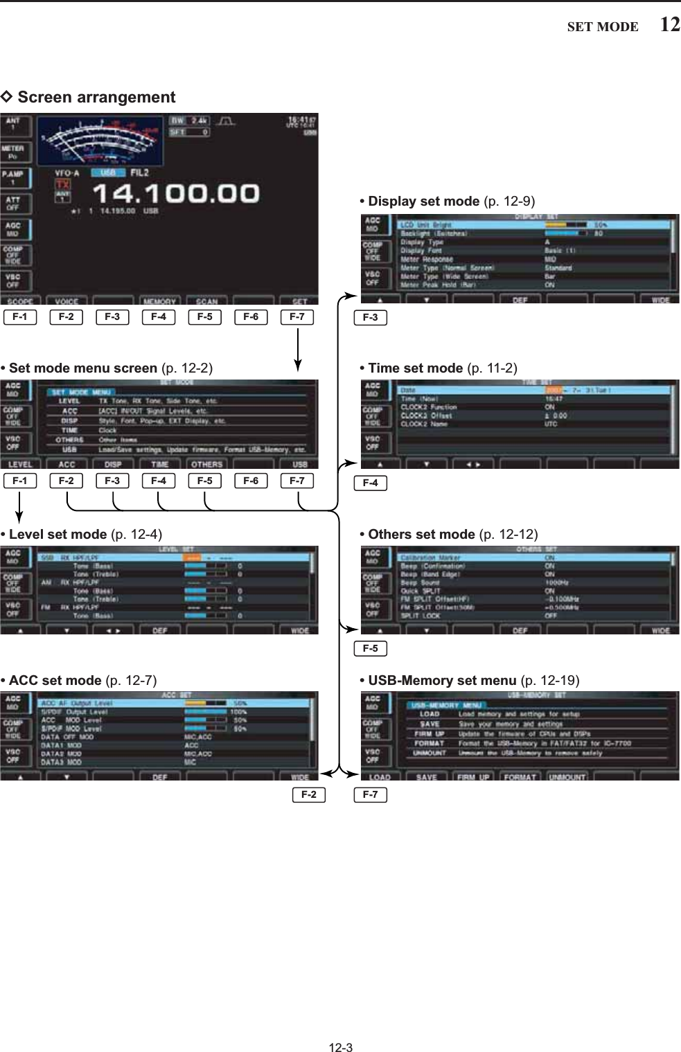
![12-2■Set mode descriptionSet mode is used for programming infrequentlychanged values or conditions of functions. The IC-7700 has a level set mode, display set mode, time setmode, accessory set mode, Others set mode andUSB-Memory set menu.DSet mode operationqPush several times to close a multi-func-tion screen, if necessary.wPush [SET] to select set mode menu screen.• Pushing and holding for 1 sec. also selects setmode menu screen.ePush [LEVEL] , [ACC] , [DISP] ,[TIME] , [OTHERS] or [USB] toenter the desired set mode.rFor level, accessory, display and Others set mode,push [WIDE] to toggle wide and normalscreen.tPush [Y] or [Z] to select the desireditem, then rotate the main dial to adjust/select thedesired value or condition.• Pushing [Ω≈] operation may be necessary forsome items.yPush twice to exit set mode.EXIT/SETF-3F-2F-1F-7F-7F-5F-4F-3F-2F-1EXIT/SETF-7EXIT/SETMain dialF-1LEVELF-2ACCF-5OTHERS EXIT/SETF-3DISPF-4TIMEF-7USB12 SET MODE](https://usermanual.wiki/ICOM-orporated/300900.User-Manual-Part-2/User-Guide-900713-Page-48.png)
![■ACC set mode 12-712SET MODESets the desired audio output level, output from[ACC1], within 0 to 100% in 1% steps.• Outputs approx. 200 mV at 50% (default) setting.ACC AF Output Level50%Sets the desired output level of [S/P DIF], within 0 to100% in 1% steps. (default: 100%)S/PDIF Output Level100%Sets the desired audio input level for modulation from[ACC1].• Approx. 100 mV at 50% (default) setting.ACC MOD Level50%Sets the desired input level for modulation from[S/P DIF], within 0 to 100% in 1% steps. (default: 50%)S/PDIF MOD Level50%Selects the desired connector(s) for modulation inputwhen data mode is not in use.• MIC : Use the signals from [MIC].• ACC : Use the signals from [ACC1] (pin 4).• MIC,ACC : Use the signals from [MIC] and [ACC1](pin 4). (default)• S/P DIF : Use the signals from [S/P DIF].DATA OFF MODMIC,ACCSelects the desired connector(s) for modulation inputwhen data 1 mode (D1) is in use.• MIC : Use the signals from [MIC].• ACC : Use the signals from [ACC1] (pin 4).(default)• MIC,ACC : Use the signals from [MIC] and [ACC1](pin 4).• S/P DIF : Use the signals from [S/P DIF].DATA1 MODACCSelects the desired connector(s) for modulation inputwhen data 2 mode (D2) is in use.• MIC : Use the signals from [MIC].• ACC : Use the signals from [ACC1] (pin 4).• MIC,ACC : Use the signals from [MIC] and [ACC1](pin 4). (default)• S/P DIF : Use the signals from [S/P DIF].DATA2 MODMIC,ACC](https://usermanual.wiki/ICOM-orporated/300900.User-Manual-Part-2/User-Guide-900713-Page-53.png)
![12-812 SET MODE■ACC set mode (continued)Selects the switching relay type for [RELAY] fromLead and MOSFET.Select the suitable relay type when connecting a non-Icom linear amplifier.• Lead : Use mechanical relay. (16 V DC/0.5 A max.; default)• MOS-FET: Use semiconductor type relay.(250 V/200 mA max.)SEND Relay TypeLeadSelects the desired item for an external meter indica-tion.• Auto : Outputs the receiving signal strength levelduring receive, and outputs the selectedlevel (selected with [METER]), duringtransmit. (default)• S : Outputs the receiving signal strength levelduring receive.• Po : Outputs the transmitting power level dur-ing transmit.• SWR : Outputs the VSWR level during transmit.• ALC : Outputs the ALC level during transmit.• COMP : Outputs the compression level duringtransmit.•VD: Outputs the drain terminal voltage of thefinal amplifier MOSFETs.•ID: Outputs the drain current of the final am-plifier MOSFETs.External Meter OutputAutoSets the output level for an external meter indicationwith in 0 to 100% range in 1% steps.• Approx. 2.5 V at 50% (default) setting for full-scale indica-tion. (4.7 kimpedance)External Meter Level50%Selects the desired connector(s) for modulation inputwhen data 3 mode (D3) is in use.• MIC : Use the signals from [MIC]. (default)• ACC : Use the signals from [ACC1] (pin 4).• MIC,ACC : Use the signals from [MIC] and [ACC1](pin 4).• S/P DIF : Use the signals from [S/P DIF].DATA3 MODMIC](https://usermanual.wiki/ICOM-orporated/300900.User-Manual-Part-2/User-Guide-900713-Page-54.png)
![12-1112SET MODESelect “ON” when the external display is connected. (default: OFF)• At least 800×600 pixel resolution is required for the dis-play.External DisplayOFFSelects the suitable pulse level for the connected ex-ternal display from H and L. (default: H)External Display Sync PulseHTurns the opening message screen indication capa-bility ON and OFF. (default: ON)Opening MessageON■Display set mode (continued)Turns the screen saver function ON (15, 30 or 60minutes) and OFF. (default: 60 min.)The screen saver will activate when no operation isperformed for the selected time period to protect theLCD from the “burn-in” effect.Screen Saver Function60minSelects the screen saver type from “Bound,” “Rota-tion” and “Twist.” (default: Bound)The screen saver indication can be displayed for yourreference while pushing and holding [PREVIEW] .F-5Screen Saver TypeBoundSets the introductory text, up to 10-character long,displayed in the opening screen.Usually, you set your call sign for the opening screen.Capital letters, small letters, numerals, some symbols(– / . @) and spaces can be used.zPush [EDIT] to select the name edit condition.• The cursor under the 1st character blinks.xPush [ABC] (MF6), [abc] (MF6), [123] (MF7) or[Symbol] (MF7) to select the character group, thenrotate the main dial to select the character.• Push [ABC] (MF6) or [abc] (MF6) to toggle capital andsmall letters.• Push [123] (MF7) or [Symbol] (MF7) to toggle numeralsand symbols.• Push [Ω] or [≈] for cursor movement.• Push [DEL] to delete the selected character.• Push [SPACE] to input a space.• Pushing the transceiver’s keypad, [0]–[9], can alsoenter numerals.cPush to set the name.EXIT/SETF-4F-3F-2F-1F-5My Call](https://usermanual.wiki/ICOM-orporated/300900.User-Manual-Part-2/User-Guide-900713-Page-57.png)
![12-1312SET MODE■Others set mode (continued)Sets the offset (difference between transmit and re-ceive frequencies) for the quick split function. This set-ting is used for HF bands in FM mode only and isused to input the repeater offset for an HF band.The offset frequency can be set from –9.999 MHz to+9.999 MHz in 1 kHz steps. (default: –0.100 MHz)FM SPLIT Offset(HF)–0.100MHzSets the offset (difference between transmit and re-ceive frequencies) for the quick split function. This set-ting is used for 50 MHz band FM mode only, and isused to input the repeater offset for the 50 MHz band.The offset frequency can be set from –9.999 MHz to+9.999 MHz in 1 kHz steps. (default: –0.500 MHz)FM SPLIT Offset(50M)–0.500MHzWhen this item is ON, the main dial can be used toadjust the transmit frequency while pushing [XFC]even while the lock function is activated. (default: OFF)See pgs. 6-6, 6-7 for split frequency operation details.SPLIT LOCKOFFThe internal antenna tuner has an automatic start ca-pability which starts tuning if the SWR is higher than1.5–3:1.• OFF : The tuner remains OFF even when the SWRis poor (1.5–3:1). (default)• ON : Automatic tune starts even when the tuner isturned OFF during HF bands operation. Tuner (Auto Start)OFFTuning of the internal antenna tuner can be startedautomatically at the moment the PTT is pushed afterthe operating frequency is changed (more than 1%from last-tuned frequency). (default: OFF)Tuner (PTT Start)OFF](https://usermanual.wiki/ICOM-orporated/300900.User-Manual-Part-2/User-Guide-900713-Page-59.png)
![12-1412 SET MODESelects the transverter operation condition from Autoand ON. (default: Auto)• ON : Turn the transverter operation ON.• Auto : The transceiver turns into transverter opera-tion condition when 2 to 13.8 V DC is appliedto [ACC2] pin 6.Transverter FunctionAutoSets the desired offset frequency for the transverteroperation within 0.000 to 99.999 MHz in 1 kHz steps.(default: 16.000 MHz)Transverter Offset16.000MHz (14.000.00 30.000.00)■Others set mode (continued)Selects the RTTY mark frequency. RTTY mark fre-quency is switched between 1275, 1615 and2125 Hz. (default: 2125 Hz)2125 Hz is automatically selected when the internalRTTY decoder is used.RTTY Mark Frequency2125Selects the RTTY shift width. There are 3 selectablevalues: 170, 200 and 425 Hz. (default: 170 Hz)170 Hz is automatically selected when the internalRTTY decoder is used.RTTY Shift Width170Selects the RTTY keying polarity. Normal or reversekeying polarity can be selected.(default: Normal)When reverse polarity is selected, Mark and Spaceare reversed.• Normal : Key open/close = Mark/Space• Reverse : Key open/close = Space/MarkRTTY Keying PolarityNormalSelects the desired PSK tone frequency for the PSKreception from 1000, 1500 and 2000 Hz. (default: 1500 Hz)PSK Tone Frequency1500Selects the speech language from English and Japan-ese. (default: English)SPEECH LanguageEnglishSelects the speech speed from HIGH (faster) andLOW (slower). (default: HIGH)SPEECH SpeedHIGH](https://usermanual.wiki/ICOM-orporated/300900.User-Manual-Part-2/User-Guide-900713-Page-60.png)
![12-1512SET MODE■Others set mode (continued)Sets the auto tuning step function for the main dial.When rotating the main dial rapidly, the tuning stepautomatically changes several times as selected. There are 2 type of auto tuning steps: HIGH (Fastest)and LOW (Faster). (default: HIGH)• HIGH : Auto tuning step is turned ON. Fastest tun-ing step during rapid rotation. (default)• LOW : Auto tuning step is turned ON. Faster tun-ing step during rapid rotation.• OFF : Auto tuning step is turned OFF.MAIN DIAL Auto TSHIGHSets the number of memo pad channels available. 5or 10 memo pads can be set. (default: 5)Memopad Numbers5The IC-7700 speech processor has frequency, modeand signal level announcement. Signal level an-nouncement can be deactivated if desired.(default: ON)When “OFF” is selected, the signal level is not an-nounced.SPEECH S-LevelONSelects the operating mode speech capability when amode switch is pushed; ON or OFF. (default: OFF)When “ON” is selected, the selected operating modeis announced when a mode switch is pushed.SPEECH [MODE] SwitchOFFSets the rate at which frequencies are scanned whenthe microphone [UP]/[DN] switches are pushed andheld. High or low can be selected.• HIGH : High speed (default; 50 tuning steps/sec.)• LOW : Low speed (25 tuning steps/sec.)MIC Up/Down SpeedHIGHSelects the RIT/∂TX frequency clearing instructionwith the switch.• ON : Clears the RIT/∂TX frequency whenis pushed momentarily. • OFF : Clears the RIT/∂TX frequency whenis pushed and held for 1 sec. (default)CLEARCLEARCLEARQuick RIT/∂TX ClearOFF](https://usermanual.wiki/ICOM-orporated/300900.User-Manual-Part-2/User-Guide-900713-Page-61.png)
![■Others set mode (continued)12-1612 SET MODESelects [DIGI-SEL] control function from DIGI-SELand APF.• DIGI-SEL : [DIGI-SEL] control functions as the digi-tal selector operation. (default)• APF : [DIGI-SEL] control functions as theaudio peak filter adjustment.DIGI–SEL VR OperationDIGI–SELSelects notch functions for SSB mode operation fromAuto, Manual and Auto/Manual.• Auto : Only the auto notch can be used.• Manual : Only the manual notch can be used.• Auto/Manual : Both the auto and manual notch canbe used. (default)[NOTCH] Switch (SSB)Auto/ManualSelects notch functions for AM mode operation fromAuto, Manual and Auto/Manual.• Auto : Only the auto notch can be used.• Manual : Only the manual notch can be used.• Auto/Manual : Both the auto and manual notch canbe used. (default)[NOTCH] Switch (AM)Auto/ManualSelects the displayed frequency shift function fromON and OFF. (default: OFF)When this function is activated, the audio pitch ortones of the received signal will remain the sameeven when the operating mode is changed betweenSSB and CW. The frequency shifting value may differ accordingto the CW pitch setting.• ON : The displayed frequency shifts when the op-erating mode is changed between SSB andCW.• OFF : The displayed frequency does not shift.SSB/CW Synchronous TuningOFFSelects the side band used to receive CW in CW nor-mal mode. (default: LSB)CW Normal SideLSBSet audio filter shape for APF from SOFT andSHARP. (default: SOFT)• SOFT : Soft filter shape makes distinguishingnoise and signals easier. The audio filterwidth is related to the CW pitch setting.• SHARP : Sharp filter shape rejects interferencesignals.APF TypeSHARP](https://usermanual.wiki/ICOM-orporated/300900.User-Manual-Part-2/User-Guide-900713-Page-62.png)
![12-1812 SET MODE■Others set mode (continued)Select [RS-232C] connector output data format fromCI-V and Decode.• CI-V : Outputs data in CI-V format. (default)• Decode : Outputs decoded contents in ASCII codeformat.RS–232C FunctionCI–VSelects data transmission speed (Baud rate) when“Decode” is selected in “RS-232C Function” above;settings are 300, 1200, 4800, 9600 and 19200 bps. (default: 9600)Decode Baud Rate9600Selects the connected keyboard type from Japanese,English, United Kingdom, French, French (Canadian),German, Portuguese, Portuguese (Brazilian), Span-ish, Spanish (Latin American) and Italian. (default: English)Keyboard TypeEnglishSets the time period for delay within 100 to1000 msec. in 50 msec. steps. (default: 250 msec.)When a key of the connected keyboard is pressedand held for the set period, the character is input con-tinuously.Keyboard Repeat Delay250msSets subnet mask for the IC-7700 when connectingto your PC or LAN (Local Area Network) through theEthernet connector.Turn the transceiver power OFF then ON to make thesetting effective. See p. 16-7 for details.Subnet Mask (Valid after Reboot)255. 255. 255. 0 (24bit)Sets the repeating rate for the connected keyboardwithin 2.0 to 30.0 cps. (default: 10.9 cps)*cps=character per secondWhen a key of the connected keyboard is pressedand held, the character is repeatedly input with the setspeed.• Available repeating rate2.0, 2.1, 2.3, 2.5, 2.7, 3.0, 3.3, 3.7, 4.0, 4.3, 4.6, 5.0,5.5, 6.0, 6.7, 7.5, 8.0, 8.6, 9.2, 10.0, 10.9, 12.0,13.3, 15.0, 16.0, 17.1, 18.5, 20.0, 21.8, 24.0, 26.7,30.0Keyboard Repeat Rate10.9cpsSets IP address for the IC-7700 when connecting toyour PC or LAN (Local Area Network) through theEthernet connector.Turn the transceiver power OFF then ON to make thesetting effective. See p. 16-7 for details.IP Address (Valid after Reboot)192. 168. 0. 1](https://usermanual.wiki/ICOM-orporated/300900.User-Manual-Part-2/User-Guide-900713-Page-64.png)
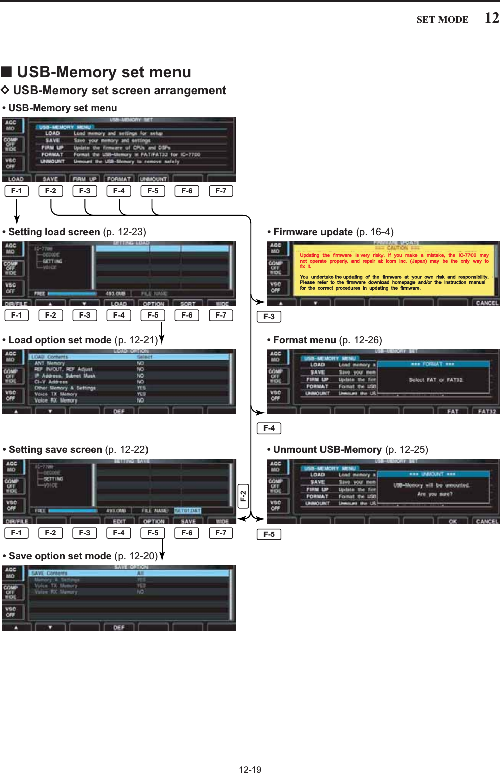
![12-2212 SET MODE■File savingMemory channel contents, set mode settings, etc. canbe saved into the USB-Memory for backup.qDuring set mode menu screen indication, push [USB] to select USB-Memory set menu screen.wPush [SAVE] to select setting save screen.eChange the following conditions if desired.• File name:zPush [EDIT] to select file name edit con-dition.• Push [DIR/FILE] several times to select thefile name, if necessary.xPush [ABC] (MF6), [123] (MF7) or [Symbol](MF7) to select the character group, then ro-tate the main dial to select the character.• [ABC] (MF6): A to Z (capital letters); [123] (MF7): 0to 9 (numerals); [Symbol] (MF7): ! # $ % & ‘ ` ^ + –= ( ) [ ] { } _ ~ @ can be selected.• Push [Ω] to move the cursor left, push [≈]to move the cursor right, push [DEL] todelete a character and push [SPACE] to in-sert a space.cPush to set the file name.• Save optionzPush [OPTION] to enter save option setmode.xPush [Y] or [Z] to select the item,then rotate the main dial to select the desiredsetting. (see p. 12-20 for details)• “Text” is the default setting.• Push and hold [DEF] for 1 sec. to select thedefault setting.cPush to return to the previous indi-cation.• Saving locationzPush [DIR/FILE] to select tree viewscreen.xSelect the desired directory or folder in theUSB-Memory.• Push [Ω≈] to select the upper directory.• Push [Y] or [Z] to select folder in thesame directory.• Push and hold [Ω≈] for 1 sec. to select afolder in the directory.• Push [REN/DEL] to rename the folder.• Push and hold [REN/DEL] for 1 sec. todelete the folder.• Push and hold [MAKE] for 1 sec. to makinga new folder. (Edit the name with the same man-ner as the “• File name” above.)cPush [DIR/FILE] twice to select the filename.rPush [SAVE] .• Confirmation screen appears.tPush [OK] to save.• After saving is completed, return to USB-Memory setmenu automatically.F-6F-6F-1F-6F-5F-5F-4F-3F-2F-4F-1EXIT/SETF-4F-2F-1F-5EXIT/SETF-4F-3F-2F-1F-1F-4F-2F-7Main dialDIR/FILE EXIT/SETF-1F-7WIDE CANCELF-5OPTIONF-6SAVE OKF-4EDIT//](https://usermanual.wiki/ICOM-orporated/300900.User-Manual-Part-2/User-Guide-900713-Page-68.png)
![12-2312SET MODE■File loadingBy loading the saved setting file from the USB-Mem-ory, you can easily set up another IC-7700—severaloperators settings can easily be applied to one IC-7700.qDuring set mode menu screen indication, push [USB] to select USB set menu screen.wPush [LOAD] to select setting load screen.• The indicator above the USB connectors and “USB” in-dicator on the display blink.• After the USB-Memory contents are displayed, the indi-cators stop blinking.ePush [OPTION] to select load option setmode, then set the desired loading conditions, if de-sired.• See page 12-21 for details.rPush [Y] or [Z] to select the desiredsetting file.tPush [LOAD] .• Confirmation screen appears.yPush [OK] to starts loading.• After the loading is completed, the message dialog, “Re-boot the IC-7700,” appears.uTurn the transceiver power OFF then ON to makethe setting effective.F-6F-4F-3F-2F-5F-1F-7DIR/FILEF-1F-7WIDE CANCELF-5OPTIONF-6SORT OKF-4LOAD//F-2∫F-3√EXIT/SET](https://usermanual.wiki/ICOM-orporated/300900.User-Manual-Part-2/User-Guide-900713-Page-69.png)
![■Changing a file nameThe file name, saved in the USB-Memory, can be re-named from the transceiver as desired.qDuring setting save screen display, push [DIR/FILE] to select tree view screen.• Push [Y] or [Z] to select the desired folder.• “DECODE,” “SETTING” and “VOICE” folders are avail-able as the default.• After the folder is selected, push and hold [Ω≈]for 1 sec. to display content folder(s), if available.wPush [DIR/FILE] to select file list screen.ePush [Y] or [Z] to select the desired file.rPush [REN/DEL] momentarily to select the filename edit condition.tPush [ABC] (MF6), [123] (MF7) or [Symbol] (MF7) toselect the character group, then rotate the main dialto select the character.• [ABC] (MF6): A to Z (capital letters); [123] (MF7): 0 to 9(numerals); [Symbol] (MF7): ! # $ % & ‘ ` ^ + – = ( ) [ ] { }_ ~ @ can be selected.• Push [Ω] to move the cursor left, push [≈] tomove the cursor right, push [DEL] to delete a char-acter and push [SPACE] to insert a space.• Pushing the transceiver’s keypad, [0]–[9], can also enternumerals.yPush to set the file name.EXIT/SETF-4F-3F-2F-1F-5F-3F-2F-1F-4F-3F-2F-1DIR/FILEF-1F-7WIDE CANCELREN/DELF-5F-4Ω ≈/F-2∫F-3√EXIT/SET12-2412 SET MODE](https://usermanual.wiki/ICOM-orporated/300900.User-Manual-Part-2/User-Guide-900713-Page-70.png)
![12-2512SET MODE■Deleting a file RECOMMENDATION! Deleting the setting file is ir-reversible. Confirm the contents before deleting asetting file!qDuring setting save screen display, push [DIR/FILE] to select tree view screen.• Push [Y] or [Z] to select the desired folder.• “DECODE,” “SETTING” and “VOICE” folders are avail-able as the default.• After the folder is selected, push and hold [Ω≈]for 1 sec. to display content folder(s), if available.wPush [DIR/FILE] to select file list screen.ePush [Y] or [Z] to select the desired fileto be deleted.rPush and hold [REN/DEL] for 1 sec. • Confirmation screen appears.tPush [OK] to delete.• After the deleting, return to setting save screen auto-matically.■Unmounting USB-MemoryCAUTION! When removing the USB-Memory, un-mount operation is necessary. If you do not unmountthe memory in this case, data in the USB memorymay be corrupted.qPush and hold [UNMOUNT] for 1 sec.• Confirmation screen appears.wPush [OK] to unmount the USB-Memory.eAfter “ ” indication disappears, remove theUSB-Memory.USBF-6F-6F-6F-5F-3F-2F-1F-4F-3F-2F-1](https://usermanual.wiki/ICOM-orporated/300900.User-Manual-Part-2/User-Guide-900713-Page-71.png)
![12-2612 SET MODE■Formatting the USB-MemorySaved data in the USB-Memory can be erased.IMPORTANT! Formatting erases all saved data inthe USB-Memory. Making a backup file on your PCis recommended.qDuring USB-Memory set menu display, push andhold [FORMAT] for 1 sec.• Confirmation screen appears.wPush [FAT] or [FAT32] to select the for-mat type, FAT or FAT32, respectively.• Confirmation screen appears.ePush [OK] to format.• Push [CANCEL] to cancel.rReturns to USB-Memory set menu indication auto-matically.NOTE: If no USB-Memory is inserted and [FOR-MAT] is selected as in step q, an error mes-sage appears.F-4F-7F-6F-7F-6F-4](https://usermanual.wiki/ICOM-orporated/300900.User-Manual-Part-2/User-Guide-900713-Page-72.png)
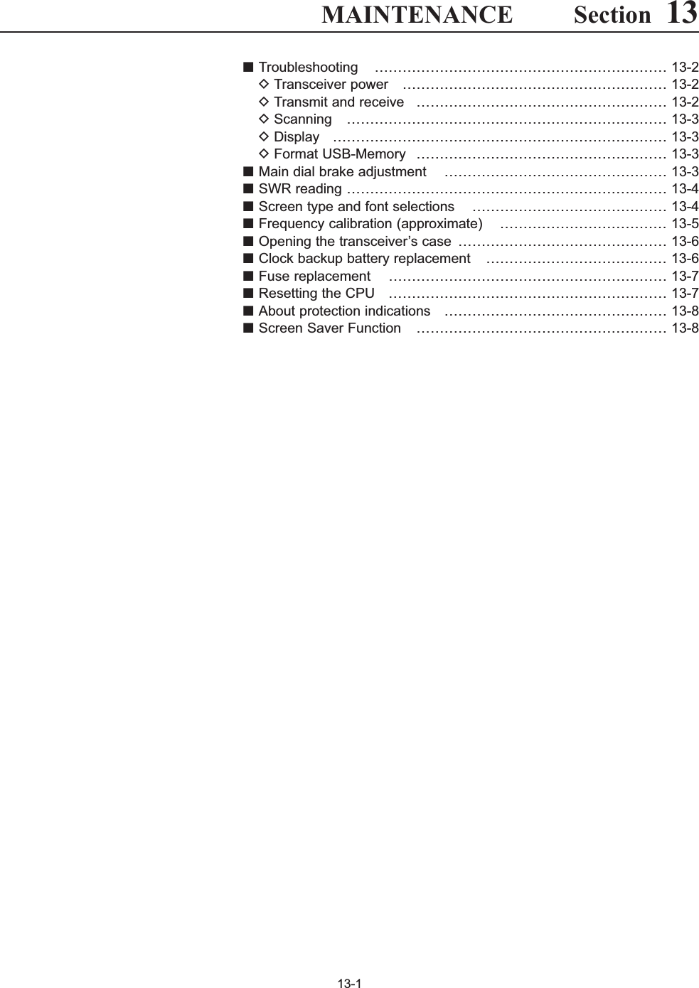
![■TroubleshootingThe following chart is designed to help you correctproblems which are not equipment malfunctions.If you are unable to locate the cause of a problem orsolve it through the use of this chart, contact you near-est Icom Dealer or Service Center.DTransceiver powerDTransmit and receivePROBLEM POSSIBLE CAUSE SOLUTION REF.No sounds from thespeaker.Sensitivity is too low, andonly strong signals areaudible.Received audio is unclearor distorted.The [ANT] switch does notfunctionTransmitting is impossible.Output power is too low.No contact possible withanother station.Transmit signal is unclearor distorted.Repeater cannot beaccessed.• Volume level is too low.• The squelch is closed.• The transceiver is in transmit.• The antenna is not connected properly.• The antenna for another band is selected.• The antenna is not properly tuned.• The attenuator is activated.• Wrong operating mode is selected.• PBT function is activated.• Noise blanker is turned ON when receiving astrong signal.• Preamp is activated.• The noise reduction is activated and the [NR]control is too far clockwise.• The antenna switch has not been activated.• The operating frequency is not inside a hamband.• [RF PWR] is set too far counterclockwise• [DRIVE] is set too far counterclockwise• [MIC] is set too far counterclockwise• The antenna for another band is selected.• The antenna is not properly tuned.• RIT or ∂TX function is activated.• Split frequency function is activated.• [MIC] is set too far clockwise• Split frequency function is not activated.• Programmed subaudible tone frequency iswrong.• Rotate [AF] clockwise to obtain a suitable lis-tening level.• Turn [SQL] to 10 o’clock position to open thesquelch.• Push [TRANSMIT] to receive or check theSEND line of an external unit, if connected.• Re-connect to the antenna connector.• Select an antenna suitable for the operatingfrequency.• Push and hold [TUNER] for 1 sec. to manuallytune the antenna.• Push [ATT] (MF4) several times to select “ATTOFF.”• Select a suitable operating mode.• Push and hold [PBT-CLR] for 1 sec. to reset thefunction.• Push [NB] to turn the noise blanker OFF.• Push [P.AMP] (MF3) once or twice to turn thefunction OFF.• Set the [NR] control for maximum readability.• Set the antenna switch in set mode to “Auto” or“Manual.”• Set the frequency to be in a ham band.• Rotate [RF PWR] clockwise.• Set [DRIVE] to a suitable position.• Set [MIC] to a suitable position.• Select an antenna suitable for the operatingfrequency.• Push and hold [TUNER] for 1 sec. to manuallytune the antenna.• Push [RIT] or [∂TX] to turn the function OFF.• Push [SPLIT] to turn the function OFF.• Set [MIC] to a suitable position.• Push [SPLIT] to to turn the function ON• Reset the frequency using set mode.p. 3-9p. 3-9p. 3-12—p. 10-2p. 10-6p. 5-9p. 3-8p. 5-12p. 5-16p. 5-9p. 5-17p. 10-4p. 3-5p. 3-12p. 3-13p. 3-12p. 10-2p. 10-6pgs. 5-10, 6-4p. 6-6p. 3-12p. 6-6p. 4-33PROBLEM POSSIBLE CAUSE SOLUTION REF.13-213 MAINTENANCEPower does not come onwhen the [POWER] switchis pushed.• Power cable is improperly connected.• The internal power supply is turned OFF.• Circuit breaker is tripped.• Re-connect the AC power cable correctly.• Turn the internal power supply ON.• Check for the cause, then re-set the circuitbreaker.p. 2-5p. 3-2—](https://usermanual.wiki/ICOM-orporated/300900.User-Manual-Part-2/User-Guide-900713-Page-74.png)
![13-3DScanningDDisplayDFormat USB-Memory13MAINTENANCEPROBLEM POSSIBLE CAUSE SOLUTION REF.Programmed scan doesnot stop.Programmed scan doesnot start.Memory scan does notstartSelect memory scan doesnot start• Squelch is open.•The same frequencies have been programmedin scan edge memory channels P1 and P2.• 2 or more memory channels have not beenprogrammed.• 2 or more memory channels have not beendesignated as select channels.• Set [SQL] to the threshold point.• Program different frequencies in scan edgememory channel P1 and P2.• Program more than 2 memory channels.• Designate more than 2 memory channels asselect channels for the scan.p. 3-9p. 8-3p. 8-3p. 9-7PROBLEM POSSIBLE CAUSE SOLUTION REF.The displayed frequencydoes not change properly.• The dial lock function is activated.• A set mode screen is selected.• The internal CPU has malfunctioned.•Push [LOCK] to turn the function OFF.• Push [EXIT/SET] several times to exit the setmode screen.• Reset the CPU.p. 5-17p. 12-2p. 13-7■Main dial brake adjustmentThe tension of the main dial may be adjusted to suityour preference.The brake adjustment is located on the bottom side ofthe front panel. See the figure at left.Slide the brake adjustment to a comfortable tensionlevel while turning the dial continuously and evenly inone direction.LightHeavy[MAIN DIAL]Brake adjustmentPROBLEM POSSIBLE CAUSE SOLUTION REF.Format error appearswhen formatting in FAT32Format error appearswhen formatting in FAT• The inserted USB-Memory capacity is smallerthan 64 MB.• The inserted USB-Memory capacity is largerthan 2 GB.•Insert a USB-Memorylarger than 64 MB orselect the FAT format.•Insert a USB-Memorysmaller than 2 GB orselect the FAT32 format.p. 12-26p. 12-26](https://usermanual.wiki/ICOM-orporated/300900.User-Manual-Part-2/User-Guide-900713-Page-75.png)
![13-4■SWR readingThe SWR meter indicates the SWR over the transmis-sion line in all modes.qPush to turn the antenna tuner OFF.wPush and hold [METER] for 1 sec. to display multi-function meter.ePush once or twice to select RTTYmode.rPush .tRotate [RF PWR] clockwise past the 12 o’clock po-sition for more than 30 W output power.yRead the SWR on the SWR meter gage.uPush to close multi-function meter.The built-in antenna tuner matches the transmitterto the antenna when the SWR is lower than 3 : 1.■Screen type and font selections2 types of screen images and 5 types of frequencyreadout indication fonts are available in the IC-7700.qPush several times to close multi-functionscreen, if necessary.wPush [SET] to select set mode menu screen.ePush [DISP] to enter display set mode.rPush [Y] or [Z] to select “Display Type”item when selecting the screen image, select “Dis-play Font” when selecting the frequency readout in-dication font.tRotate the main dial to select the desired screenimage or font.• Screen image is selectable from A (Black back) and B(Blue back).• Basic (1), Basic (2), Italic, Round and Slim are availablefor the frequency readout font.yPush twice to exit from display set mode.EXIT/SETF-2F-1F-3F-7EXIT/SETEXIT/SETTRANSMITRTTY/PSKTUNERS1000125101010 2044 52V50 100 150 200 2501531.5IDVDdBWAPoSWRCOMP ALC59+20 +40 +60dB∞Better than 1.5:1[RF PWR] RTTY/PSK EXIT/SETTUNERTRANSMIT METER13 MAINTENANCE• Screen image example— Display Type: B, Display Font: Slim](https://usermanual.wiki/ICOM-orporated/300900.User-Manual-Part-2/User-Guide-900713-Page-76.png)
![13-5■Frequency calibration (approximate)A very accurate frequency counter is required to cali-brate the frequency of the transceiver. However, arough check may be performed by receiving radio sta-tion WWV, WWVH, or other standard frequency sig-nals.CAUTION: The IC-7700 has been thoroughly ad-justed and tested at the factory before beingshipped. You should not have to re-calibrate it.qPush to select USB mode.wPush and hold for 1 sec. to clear thePBT setting and make sure that the RIT/∂TX func-tion is not activated.eSet the frequency to the standard frequency stationminus 1 kHz.• When receiving WWV or WWVH (at 15.00000 MHz) asa standard frequency, set the operating frequency for14.99900 MHz.• Other standard frequencies can be used.rPush several times to close a multi-func-tion screen, if necessary.• Calibration marker item tPush [SET] to select set mode menu screen.yPush [OTHERS] to enter Others set mode.uPush [Y] several times to select the “Calibra-tion Marker” item.iRotate the main dial clockwise to turn the calibra-tion marker ON.oPush once to return to set mode menuscreen.!0 Push [ACC] to enter accessory set mode.!1 Push [Z] several times to select the “REF Ad-just” item.!2 Rotate the main dial to adjust for a zero beat withthe received standard signal as shown at left.• REF Adjust item• Zero beat means that two signals are exactly the samefrequency, resulting in a single tone being emitted.!3 Turn the calibration marker OFF in Others setmode.!4 Push twice to exit set mode.EXIT/SETF-2F-2EXIT/SETF-1F-5F-7EXIT/SETPBT-CLRSSBMain dialF-2F-1ACCF-5OTHERS EXIT/SETF-7SET/∫ √13MAINTENANCE](https://usermanual.wiki/ICOM-orporated/300900.User-Manual-Part-2/User-Guide-900713-Page-77.png)
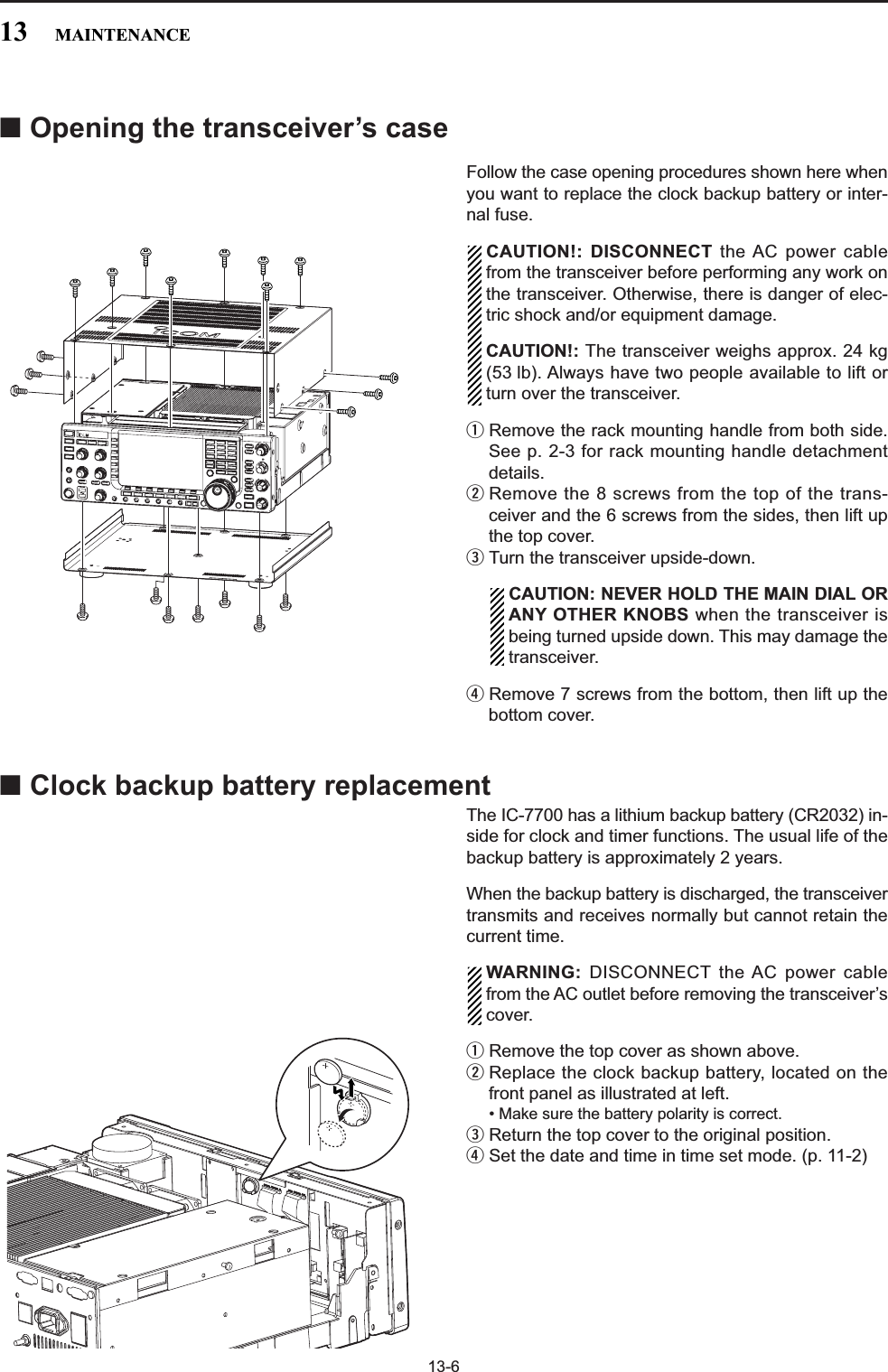
![13-7■Fuse replacementWhen no external DC output is available from [EXTDC] and ACC connectors, the internal fuse may beopen. Replace the fuse in this case.WARNING: DISCONNECT the AC power cablefrom the AC outlet before removing the transceiver’scover.qRemove the bottom cover as shown left.wRemove the 8 screws from the shield cover of thetransceiver’s bottom side.eReplace the open fuse with a new, properly ratedone (FGB 2 A) as shown at left.rReturn the inside cover and bottom cover andscrews to the original position.■Resetting the CPUqTurn the main power switch on the rear panel ON.• Make sure the transceiver power is still OFF.wWhile pushing and holding and ,push to turn power ON.• The internal CPU is reset.• The CPU start-up takes approx. 5 sec.• The transceiver displays its initial VFO frequencieswhen resetting is complete.eCorrect the set mode settings after resetting, if de-sired.NOTE: Resetting CLEARS all programmed con-tents in memory channels and returns programmedvalues in set mode to default values.POWERMWF-INPENTMW F-IMP ENTPOWER13MAINTENANCEALL CLEAR](https://usermanual.wiki/ICOM-orporated/300900.User-Manual-Part-2/User-Guide-900713-Page-79.png)
![13-8■About protection indicationsThe IC-7700 has a 2-step protection function to protectthe final power amplifiers.The protector monitors the power amplifier tempera-ture and activates when the temperature becomes ex-tremely high.• Power down transmissionReduces the transmit output power to 100 W.“LMT” appears beside the transmit indicator duringtransmit.• Transmission inhibitDeactivates the transmitter. The transmit indicator is displayed in gray duringtransmit.When the protector is activated, wait until the poweramplifier cools down using the transceiver in stand-by or receive condition.NOTE: DO NOT turn the transceiver power OFFwhen the protector is ON. If you do, the cooling fanwill not function and it will take longer to cool thetransceiver.The power amplifier temperature can be monitored inthe multi-function meter, TEMP gauge.■Screen saver functionThe IC-7700 has a screen saver function to protect theLCD from the “burn-in” effect.qPush several times to close a multi-func-tion screen, if necessary.wPush [SET] to select set mode menu screen.ePush [DISP] to enter display set mode.rPush [Y] or [Z] several times to selectthe “Screen Saver Function” item.tRotate the main dial to select the desired time pe-riod for the screen saver activation from 15, 30,60 min. and OFF.• Deactivate the screen saver with “OFF” selection.yPush [Z] to select the “Screen Saver Type”item.uRotate the main dial to select the screen saver typefrom “Bound,” “Rotation” and “Twist.”• Push and hold [PREVIEW] to display the indica-tion for your reference.iPush twice to exit set mode.EXIT/SETF-5F-2F-2F-1F-3F-7EXIT/SETCheck the temperatureMain dialF-2 F-3F-1DISPF-5PREVIEW EXIT/SETF-7SET∫ √13 MAINTENANCE](https://usermanual.wiki/ICOM-orporated/300900.User-Manual-Part-2/User-Guide-900713-Page-80.png)
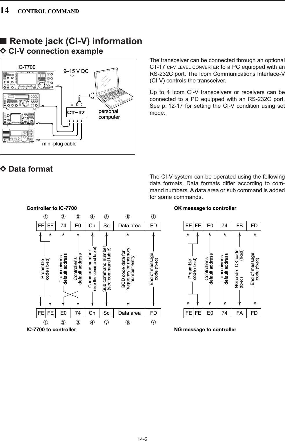
![14-3DCommand table14CONTROL COMMAND00 — Send frequency data01 Same as Send mode datacommand 0602 — Read band edge frequencies03 — Read operating frequency04 — Read operating mode05 — Set operating frequency 06 00 Select LSB01 Select USB02 Select AM03 Select CW04 Select RTTY05 Select FM07 Select CW-R08 Select RTTY-R12 Select PSK13 Select PSK-R07 — Select VFO mode00 Select VFO-A01 Select VFO-BA0 Equalize VFO-A and VFO-BB0 Exchange VFO-A and VFO-B08 — Select memory mode0001–0101* Select memory channel*P1=0100, P2=010109 — Memory write0A — Memory to VFO0B — Memory clear0E 00 Scan stop01 Programmed/memory scan start02 Programmed scan start03 ∂F scan start12 Fine programmed scan start13 Fine ∂F scan start22 Memory scan start23 Select memory scan startA1–A7 Set ∂F scan span (A1=±5 kHz;A2=±10 kHz; A3=±20 kHz;A4=±50 kHz; A5=±100 kHz; A6=±500 kHz; A7=±1 MHz)B0 Set as non-select channelB1 Set as select channel (1=★1; 2=★2; 3=★3; when nodata command is specified, thepreviously set number or “★1” isselected)B2 Set the number for select memoryscan (0=ALL; 1=★1; 2=★2; 3=★3)D0 Set scan resume OFFD3 Set scan resume ON0F 00 Turn the split function OFF01 Turn the split function ON10 00 Select 10 Hz (1 Hz) tuning step01 Select 100 Hz tuning step02 Select 1 kHz tuning step03 Select 5 kHz tuning step04 Select 9 kHz tuning step05 Select 10 kHz tuning step06 Select 12.5 kHz tuning step07 Select 20 kHz tuning step08 Select 25 kHz tuning step11 — Select/read attenuator (0=OFF; 1=6 dB; 2=12 dB;3=18 dB)12 00 + RX ANT Select/read ANT1 selection(00=RX ANT OFF; 01=RX ANT ON)01 + RX ANT Select/read ANT2 selection(00=RX ANT OFF; 01=RX ANT ON)02 + RX ANT Select/read ANT3 selection(00=RX ANT OFF; 01=RX ANT ON)03 + RX ANT Select/read ANT4 selection(00=RX ANT OFF; 01=RX ANT ON)13 00 Announce with voice synthesizer01 (00=all data; 01=frequency and 02 S-meter level; 02=receive mode)14 01 + Level data [AF] level setting (0=max. CCW to 255=max. CW)02 + Level data [RF] level setting (0=max. CCW to 255=11 o’clock)03 + Level data [SQL] level setting (0=11 o’clock to 255=max. CW)05 + Level data [APF] level setting(0=Pitch–550 Hz, 128=Pitch,255=Pitch+550 Hz; 10 Hz steps)06 + Level data [NR] level setting (0=min. to 255=max.)07 + Level data Inside [TWIN PBT] setting or IFshift setting (0=max. CCW,128=center, 255=max. CW)08 + Level data Outside [TWIN PBT] setting (0=max. CCW, 128=center,255=max. CW)09 + Level data [CW PITCH] setting (0=300 Hz, 128=600 Hz,255=900 Hz; 5 Hz steps)0A + Level data [RF POWER] setting (0=max.CCW to 255=max. CW)0B + Level data [MIC] setting (0=max. CCW to255=max. CW)0C + Level data [KEY SPEED] setting (0=max.CCW to 255=max. CW)0D + Level data [NOTCH] setting (0=low freq. to 255=high freq.)0E + Level data [COMP] setting (0=max. CCW to 255=max. CW)0F + Level data [DELAY] setting (0=max. CCW to 255=max. CW)11 + Level data [AGC] control setting (0=max. CCW to 255=max. CW)12 + Level data [NB] control setting (0=max. CCW to 255=max. CW)13 + Level data [DIGI-SEL] setting (0=max. CCW to 255=max. CW)14 + Level data [DRIVE] setting (0=max. CCW to 255=max. CW)15 + Level data [MONI GAIN] setting (0=max.CCW to 255=max. CW)16 + Level data [VOX GAIN] setting (0=max.CCW to 255=max. CW)17 + Level data [ANTI VOX] setting (0=max. CCW to 255=max. CW)Command Sub command Description Command Sub command Description](https://usermanual.wiki/ICOM-orporated/300900.User-Manual-Part-2/User-Guide-900713-Page-83.png)
![14-4DCommand table (continued)14 CONTROL COMMAND14 18 + Level data [CONTRAST] setting (0=max.CCW to 255=max. CW)19 + Level data [BRIGHT] setting (0=max. CCW to 255=max. CW)15 01 Read squelch condition02 Read S-meter level11 Read RF power meter 12 Read SWR meter 13 Read ALC meter 14 Read COMP meter 15 Read VDmeter16 Read IDmeter16 02 Send/read Preamp setting(0=OFF; 1=preamp 1;2=preamp 2)12 Send/read AGC selection (0=OFF; 1=Slow; 2=Mid; 3=Fast)22 Send/read noise blanker setting(0=OFF; 1=ON)32 Send/read Audio peak filter set-ting for CW mode(APF type=SHARP: 0=OFF;1=320 Hz; 2=160 Hz; 3=80 Hz,APF type=SOFT: 0=OFF;1=WIDE; 2=MID; 3=NAR)40 Send/read noise reduction setting(0=OFF; 1=ON)41 Send/read auto notch setting(0=OFF; 1=ON)42 Send/read repeater tone setting(0=OFF; 1=ON)43 Send/read tone squelch setting(0=OFF; 1=ON)44 Send/read speech compressorsetting (0=OFF; 1=ON)45 Send/read monitor setting(0=OFF; 1=ON)46 Send/read VOX function setting(0=OFF; 1=ON)47 Send/read Break-in function set-ting (0=OFF; 1=semi break-in;2=full break-in)48 Send/read manual notch setting(0=OFF; 1=ON)4C Send/read VSC setting(0=OFF; 1=ON)4D Send/read Manual AGC setting(0=OFF; 1=ON)4E Send/read DIGI-SEL setting(0=OFF; 1=ON)4F Send/read twin peak filter setting(0=OFF; 1=ON)50 Send/read dial lock function set-ting (0=OFF; 1=ON)53 Send/read RX antenna connectorsetting (0=OFF; 1=ON)19 00 Read the transceiver ID1A 00 Send/read memory contents (seep. 14-9 for details)01 Send/read band stacking registercontents (see p. 14-9 for details)02 Send/read memory keyer con-tents (see p. 14-9 for details)1A 03 Send/read the selected filter width(SSB, CW, PSK: 0=50 Hz to40=3600 Hz; RTTY: 0=50 Hz to31=2700 Hz; AM: 0=200 Hz to49=10 kHz)04 Send/read the selected AGC timeconstant (0=OFF, 1=0.1/0.3 sec.to 13=6.0/8.0 sec.)050001 Send/read SSB RX HPF/LPF(HPF: 0=Through, 1=100 to20=2000, LPF: 5=500 to24=2400, 25=Through)050002 Send/read SSB RX Tone (Bass)level (0 =–5 to 10=+5)050003 Send/read SSB RX Tone (Treble)level (0=–5 to 10=+5)050004 Send/read AM RX HPF/LPF(HPF: 0=Through, 1=100 to20=2000, LPF: 5=500 to24=2400, 25=Through)050005 Send/read AM RX Tone (Bass)level (0 =–5 to 10=+5)050006 Send/read AM RX Tone (Treble)level (0=–5 to 10=+5)050007 Send/read FM RX HPF/LPF(HPF: 0=Through, 1=100 to20=2000, LPF: 5=500 to24=2400, 25=Through)050008 Send/read FM RX Tone (Bass)level (0 =–5 to 10=+5)050009 Send/read FM RX Tone (Treble)level (0=–5 to 10=+5)050010 Send/read CW RX HPF/LPF(HPF: 0=Through, 1=100 to20=2000, LPF: 5=500 to24=2400, 25=Through)050011 Send/read RTTY RX HPF/LPF(HPF: 0=Through, 1=100 to20=2000, LPF: 5=500 to24=2400, 25=Through)050012 Send/read PSK RX HPF/LPF(HPF: 0=Through, 1=100 to20=2000, LPF: 5=500 to24=2400, 25=Through)050013 Send/read SSB TX Tone (Bass)level (0 =–5 to 10=+5)050014 Send/read SSB TX Tone (Treble)level (0=–5 to 10=+5)050015 Send/read AM TX Tone (Bass)level (0 =–5 to 10=+5)050016 Send/read AM TX Tone (Treble)level (0=–5 to 10=+5)050017 Send/read FM TX Tone (Bass)level (0 =–5 to 10=+5)050018 Send/read FM TX Tone (Treble)level (0=–5 to 10=+5)050019 Send/read SSB TX bandwidth forwide (see p. 14-10 for details)050020 Send/read SSB TX bandwidth formid. (see p. 14-10 for details)050021 Send/read SSB TX bandwidth fornarrow (see p. 14-10 for details)050022 Send/read speech level (0=0% to 255=100%)Command Sub command Description Command Sub command Description](https://usermanual.wiki/ICOM-orporated/300900.User-Manual-Part-2/User-Guide-900713-Page-84.png)
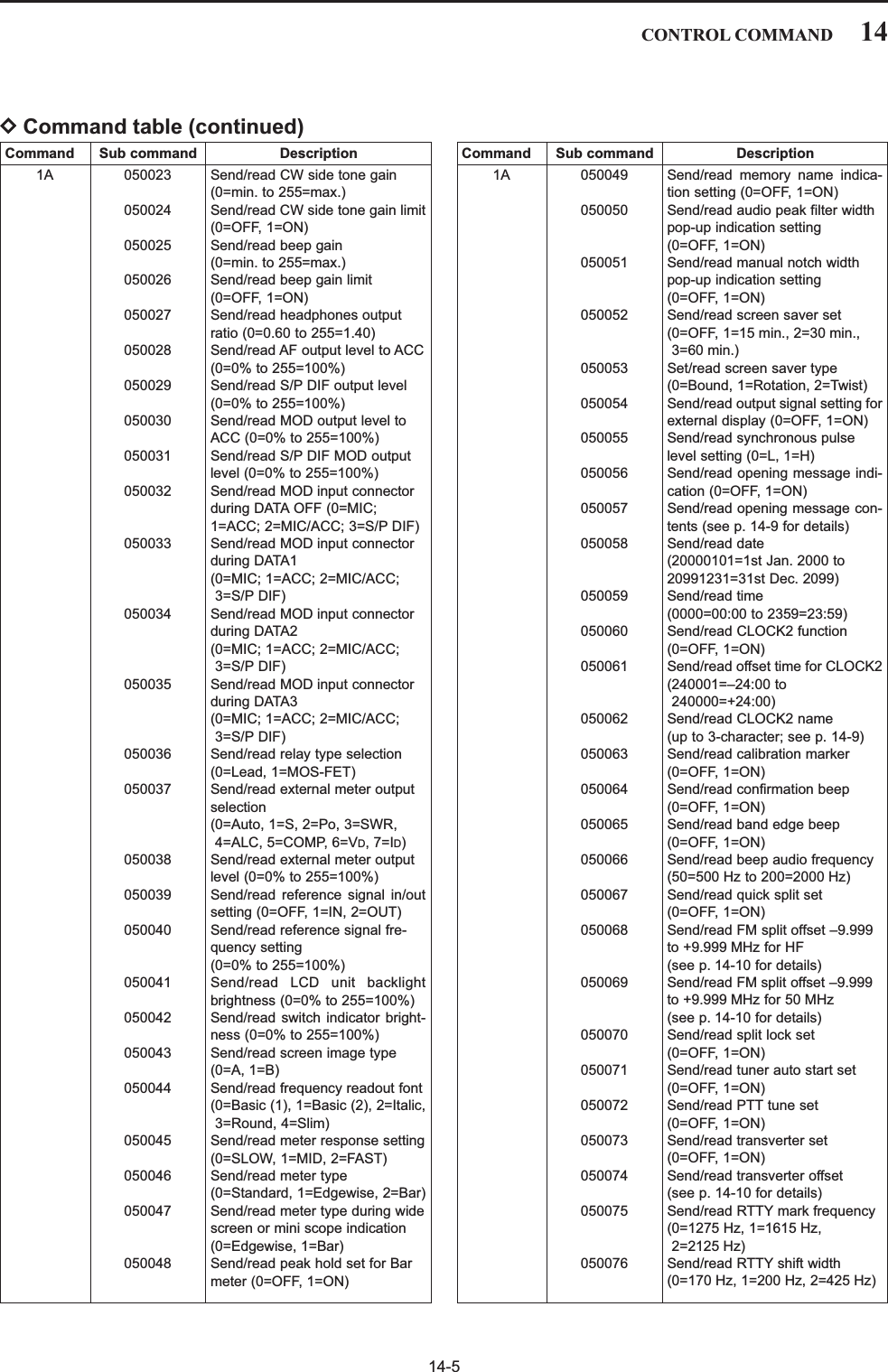
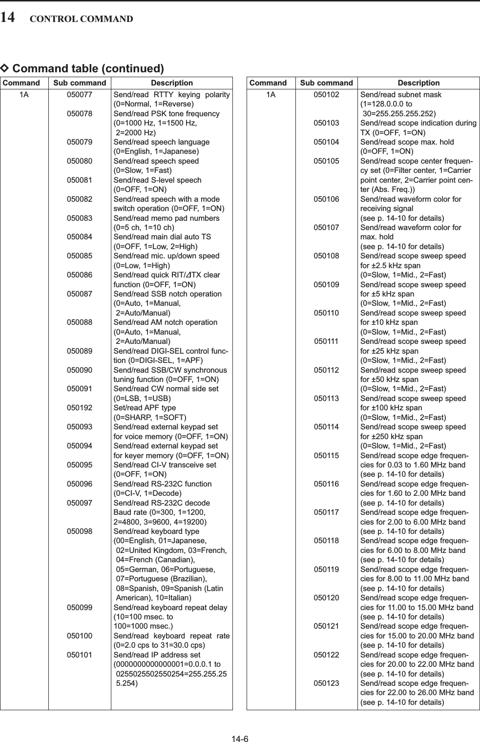
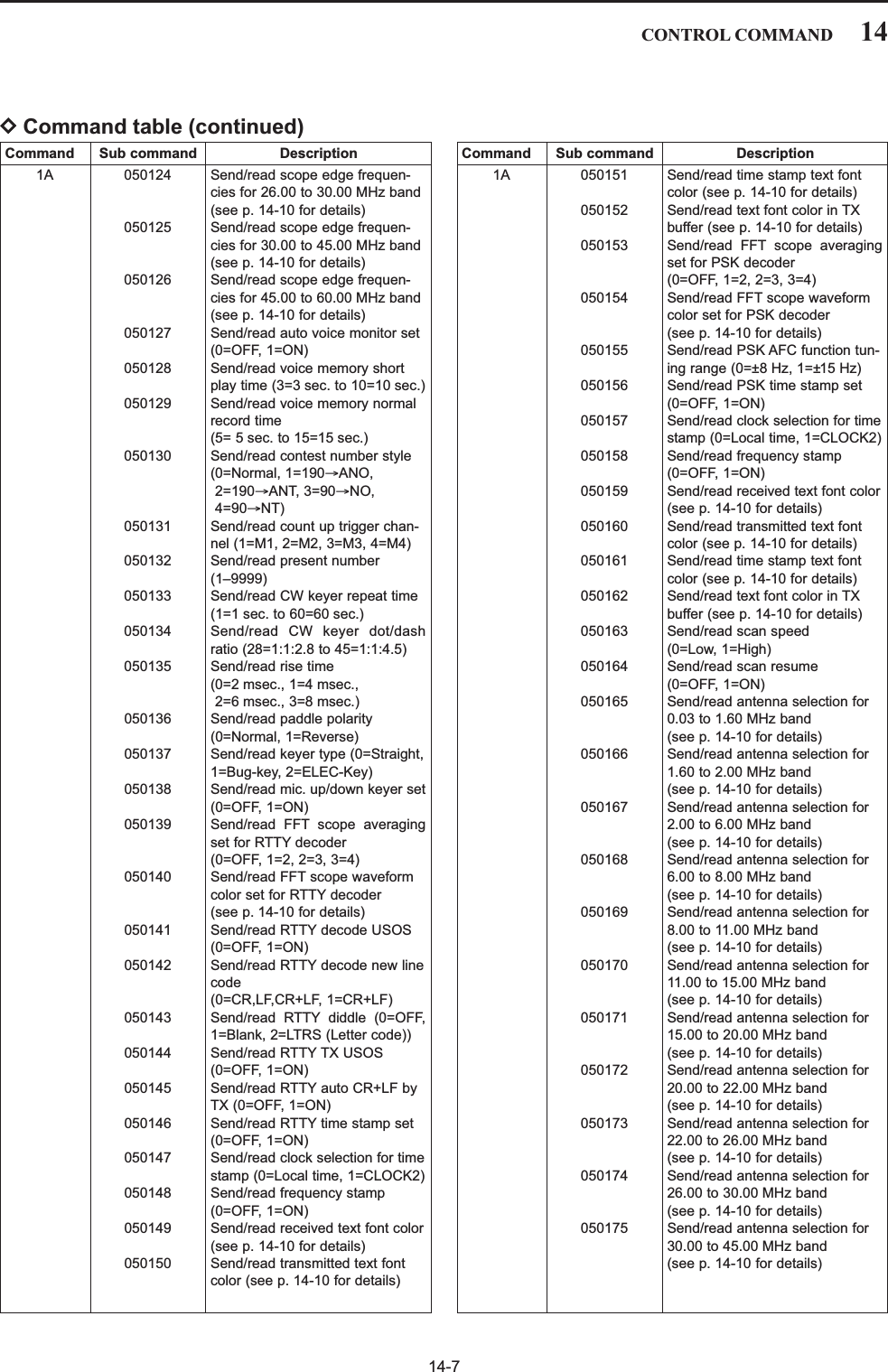
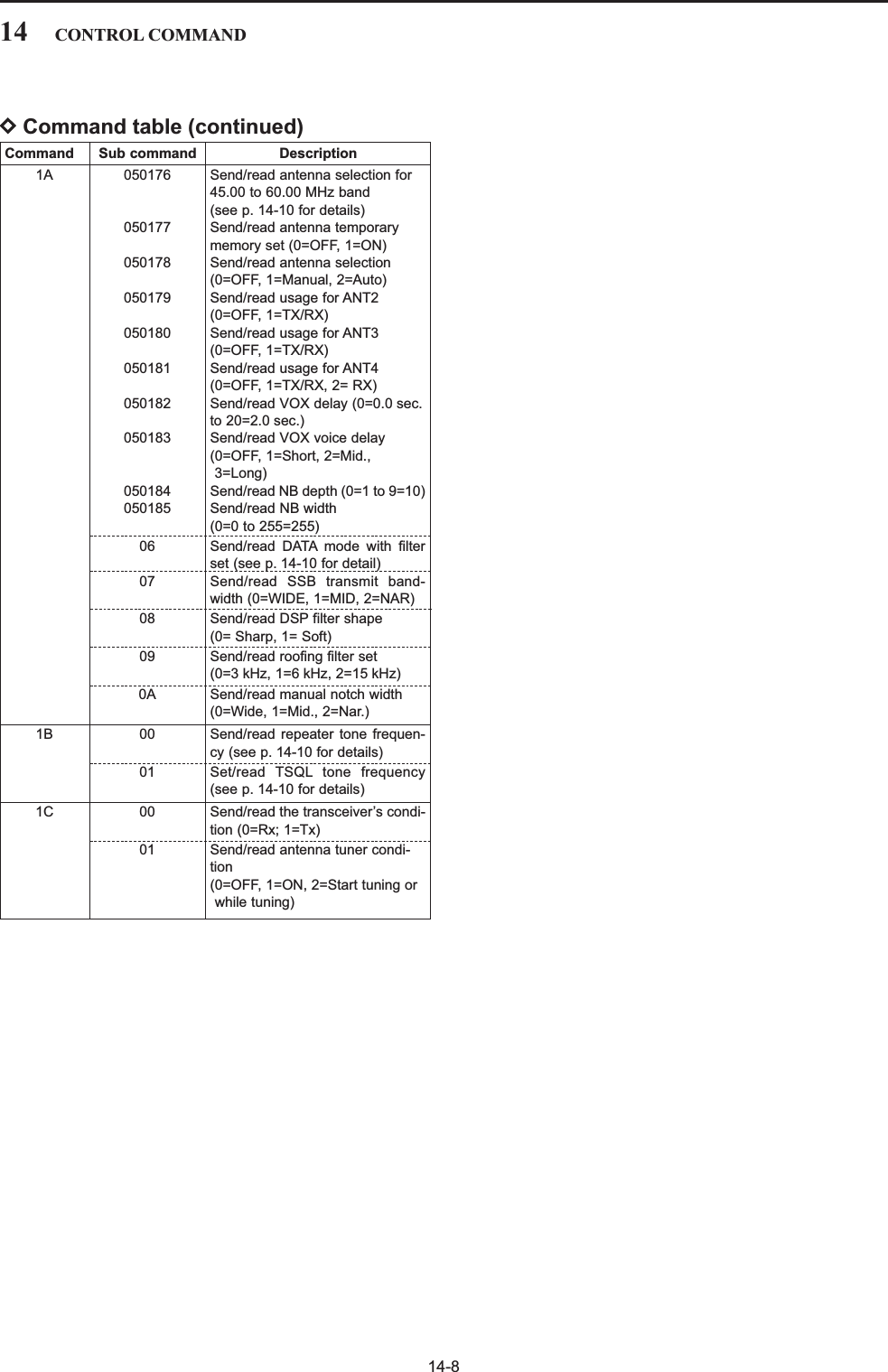
![14-914CONTROL COMMANDDTo send/read memory contentsWhen sending or reading memory contents, additionalcodes must be added to append the memory channelas follows.➥Additional code: 0000–0101 (0100=P1, 0101=P2)DBand stacking registerTo send or read the desired band stacking register’scontents, combined codes of the frequency band andregister codes as follows are used. For example, when sending/reading the oldest con-tents in the 21 MHz band, the code “0703” is used.• Frequency band code • Register code DCodes for memory keyer contentsTo send or read the desired memory keyer contents,the channel and character codes as follows are used. • Channel code • Character’s code DCodes for memory name, openingmessage and CLOCK2 name contentsTo send or read the desired memory name settings,the character codes, instructed codes for memorykeyer contents as above, and follows are used. •Character’s code— Alphabetical characters•Character’s code— Symbols Character ASCII code Character ASCII codea–z 61–7A — —Code Frequency band Frequency range (unit: MHz)01 1.8 1.800000– 1.99999902 3.5 3.400000– 4.09999903 7 6.900000– 7.49999904 10 9.900000–10.49999905 14 13.900000–14.49999906 18 17.900000–18.49999907 21 20.900000–21.49999908 24 24.400000–25.09999909 28 28.000000–29.99999910 50 50.000000–54.00000012 GENE Other than aboveCode Registered number01 1 (latest)02 203 3 (oldest)Character ASCII code Description0–9 30–39 NumeralsA–Z 41–5A Alphabetical charactersspace 20 Word space / 2F Symbol? 3F Symbol, 2C Symbol. 2E Symbol^ 5E e.g., to send BT, enter ^4254✱2A Inserts contest number (can beused for 1 channel only)Code Channel number01 M102 M203 M304 M4Character ASCII code Character ASCII code! 21#23$24%25&26¥5C?3F ” 22’27`60+2B–2D:3A;3B=3D<3C>3E ( 28)29[5B]5D{7B}7D|7C_5F–7E@40](https://usermanual.wiki/ICOM-orporated/300900.User-Manual-Part-2/User-Guide-900713-Page-89.png)
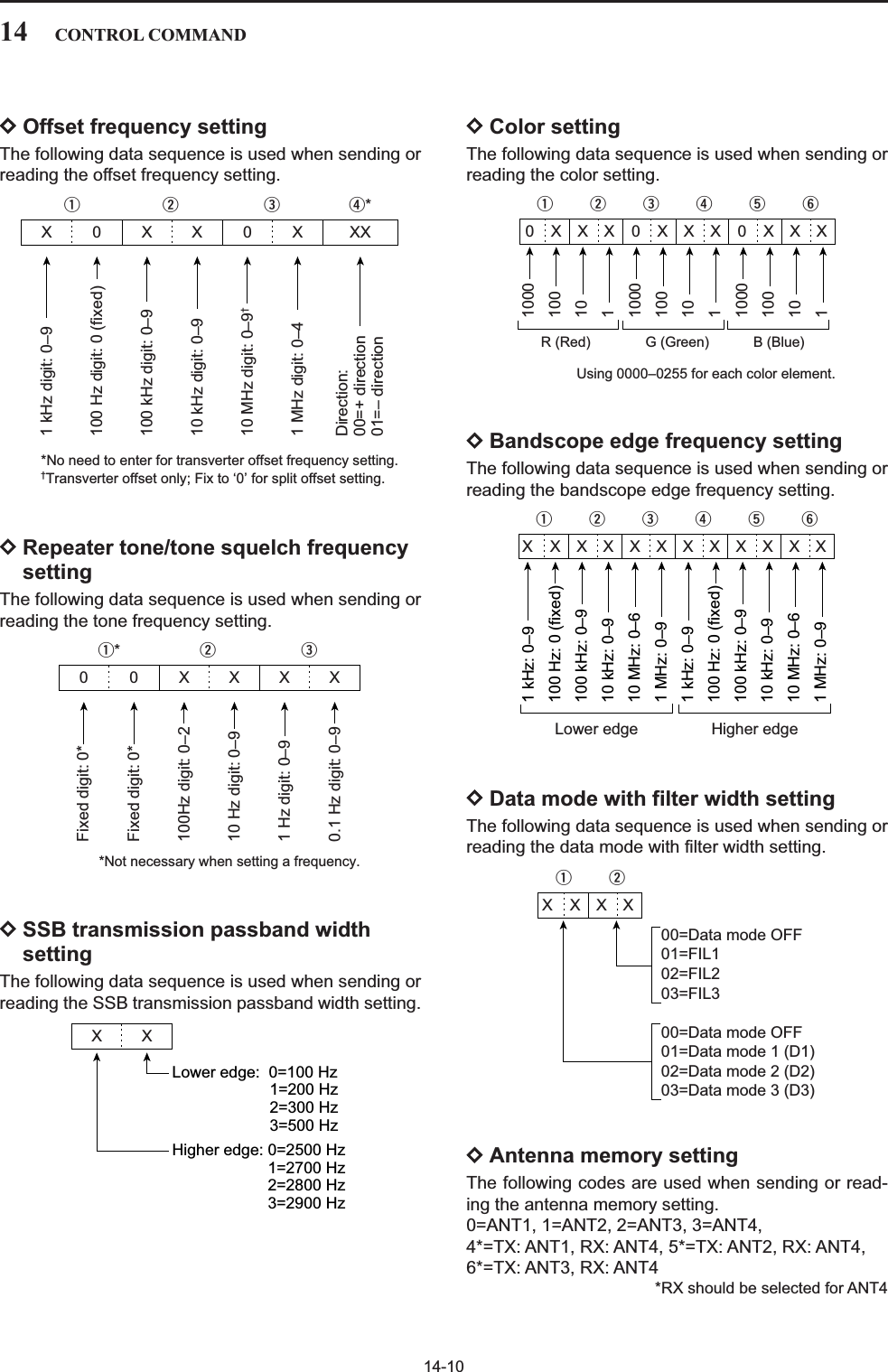
![15-2■SpecificationsDGeneral• Frequency coverage (unit: MHz) :Receiver 0.030000–60.000000*1Transmitter 1.800000–1.999999*2, 3.500000–3.999999*2,5.330500*3, 5.346500*3, 5.366500*3, 5.371500*3,5.403500*3, 7.000000–7.300000*2,10.100000–10.150000*2, 14.000000–14.350000*2,18.068000–18.168000*2, 21.000000–21.450000*2,24.890000–24.990000*2, 28.000000–29.700000*2,50.000000–54.000000*2*1Some frequency ranges are not guaranteed.*2Depending on versions. *3USA version only.• Operating mode : USB, LSB, CW, RTTY, PSK31, AM, FM• Number of memory channels : 101 (99 regular, 2 scan edges)• Antenna connector : SO-239×4 (antenna impedance: 50 )• Operating temperature range : 0˚C to +50˚C; +32˚F to +122˚F• Frequency stability : Less than ±0.05 ppm (approx. 5 min. after from turnthe main power, [I/O], ON, 0–50˚C; 32–122˚F)• Frequency resolution : 1Hz• Power supply requirement : 85–265 V AC (universal input)• Power consumption :Receive Stand-by 200 VA typicalMax. audio 210 VA typicalTransmit at 200 W 800 VA• Dimensions (projections not included) :425×149×437 mm; 1623⁄32×57⁄8×177⁄32 in• Weight : Approx. 22.5 kg; 50 lb• ACC 1 connectors : 8-pin DIN connector• ACC 2 connectors : 7-pin DIN connector• Display*:7-inch (diagonal) TFT color LCD (800×480)• EXT-DISPLAY connector : D-sub 15S • CI-V connector : 2-conductor 3.5 (d) mm (1⁄8w)• RS-232C connector : D-sub 9-pin• USB connector : USB (Universal Serial Bus)1.1/2.0×2DTransmitter• Transmit output power :SSB, CW, RTTY, PSK31, FM5–200 WAM 5–50 W• Modulation system :SSB P.S.N. modulationAM Low power modulationFM Phase modulation• Spurious emission : More than 60 dB (HF bands)More than 70 dB (50 MHz band)• Carrier suppression : More than 63 dB• Unwanted side-band suppression : More than 80 dB•∂TX variable range : ±9.999 kHz• Microphone connector : 8-pin connector (600 )• ELEC-KEY connector : 3-conductor 6.35 (d) mm (1⁄4w)• KEY connector : 3-conductor 6.35 (d) mm (1⁄4w)• RELAY connector : Phono (RCA)• ALC connector : Phono (RCA)15 SPECIFICATIONS AND OPTIONS](https://usermanual.wiki/ICOM-orporated/300900.User-Manual-Part-2/User-Guide-900713-Page-92.png)
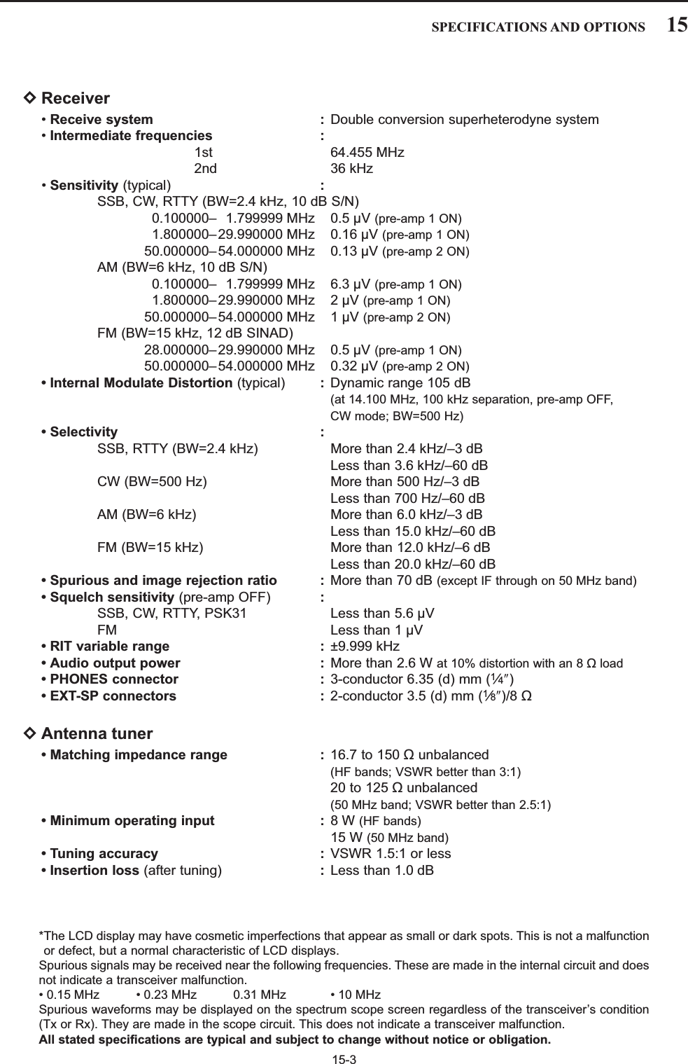
![15-4■Options•IC-PW1/EURO HF/50MHzALL BAND1kW LINEAR AMPLIFIERFull-duty-cycle 1 kW linear amplifier including an auto-matic antenna tuner. Has automatic tuning and bandselection capability when used with an Icom trans-ceiver. Full break-in (QSK) operation. Theamplifier/power supply unit and the remote control unitare separate.•SM-20 DESKTOP MICROPHONEUnidirectional, electret microphone for base stationoperation. Includes [UP]/[DOWN] switches and a lowcut function.•CT-17 CI-V LEVEL CONVERTERFor remote transceiver control using a PC. You canchange frequencies, operating mode, memory chan-nels, etc. (software is not included)•SP-20 EXTERNAL SPEAKER4 audio filters; headphone jack; can connect to 2transceivers.• Input impedance : 8 • Max. input power : 5 W•HM-36 HAND MICROPHONEHand microphone equipped with [UP]/[DOWN] switch-es.15 SPECIFICATIONS AND OPTIONS](https://usermanual.wiki/ICOM-orporated/300900.User-Manual-Part-2/User-Guide-900713-Page-94.png)
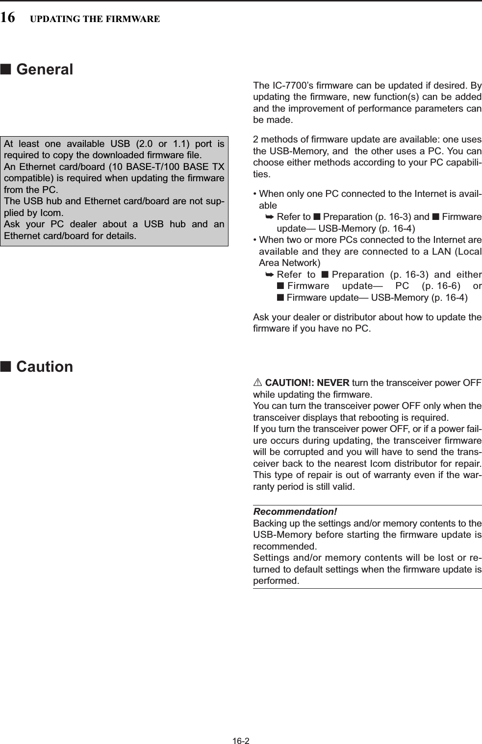
![16-3■PreparationDFirmware and firm utility The latest firmware and the firm utility can be down-loaded from the Icom home page via the Internet. Ac-cess the following URL to download the firm utility andthe latest firmware.http://www.icom.co.jp/world/support/index.htmFor updating from the USB-MemoryWhen updating the firmware from the USB-Memory,copy the downloaded firmware data (e.g. 7700_110.dat)to the USB-Memory (in “IC-7700” folder) using an avail-able USB port (USB hub may be required; purchased sep-arately from your PC dealer).DFile downloadingqAccess the following URL directly.http://www.icom.co.jp/world/support/index.htmwClick “Firmware Updates/Software Downloads” linkthen click the firmware file link.eRead “Regarding this Download Service” carefully,then click [AGREE].rClick [Save] in the displayed File Download dialog.tSelect the desired location in which you want tosave the firmware, then click [Save] in the displayedFile Download dialog.• File download starts.yAfter download is completed, extract the file.• The firmware and the firm utility are compressed in “zip”format, respectively.• When updating the transceiver using with the USB-Memory, copy the extracted firmware (e.g.7700_110.dat) to the USB-Memory IC-7700 folder.• The USB-Memory must have been formatted by the IC-7700. (p. 12-26)Select the savinglocationClick7700_110.datClick16UPDATING THE FIRMWAREClickRead carefully](https://usermanual.wiki/ICOM-orporated/300900.User-Manual-Part-2/User-Guide-900713-Page-97.png)
![16-4■Firmware update— USB-MemoryWhen updating the firmware with the USB-Memory, noIP address or subnet mask settings are necessary. qCopy the downloaded firmware data into the USB-Memory (“IC-7700” folder).• The USB-Memory must have been formatted by the IC-7700.wInsert the USB-Memory into the USB connector.ePush several times to close a multi-func-tion screen, if necessary.rPush [SET] to select set mode menu screen.tPush [USB] to select USB-Memory set menu.yPush and hold [FIRM UP] for 1 sec.uRead the displayed precaution carefully.• Push [Y] or [Z] to scroll the indication.• Push [CANCEL] to cancel the firmware updating.iAfter you read and understand all of the precau-tions, push [OK] .• [OK] appears only following the precautions.• Push [CANCEL] to cancel the firmware updating.oPush [Y] or [Z] to select the firmwarefile, then push [FIRM UP] .!0 Read the displayed precautions carefully.!1 If you agree, push and hold [OK] for 1 sec. tostart the firmware update.• Push [CANCEL] to cancel the firmware updating.!2 While loading the firmware from the USB-Memory,the dialog as at left is displayed.F-7F-6F-4F-3F-2F-7F-6F-6F-7F-2F-1F-3F-7F-7EXIT/SET/∫DIR/FILEF-1F-7USB CANCELFIRM UPFIRM UPF-6OKF-3F-4/SET ///F-2√ ∫√EXIT/SET16 UPDATING THE FIRMWARE](https://usermanual.wiki/ICOM-orporated/300900.User-Manual-Part-2/User-Guide-900713-Page-98.png)
![16-5!3 After the firmware loading is completed, the trans-ceiver starts the update automatically and the dia-log at left is displayed.RWARNING!: NEVER turn the IC-7700 powerOFF at this stage.The transceiver firmware will be corrupted.!4 When the dialog disappears, the precaution at leftis displayed.!5 Read the precaution carefully, and then push [OK] .• Return to USB-Memory set menu.!6 Push to turn the IC-7700 power OFF, thenON again.!7 Depending on the update, one or two dialog boxesas at left appear in sequence.RWARNING!: NEVER turn the IC-7700 powerOFF at this stage.The transceiver firmware will be corrupted.!8 After the dialog disappears, the firmware updatingis completed and normal operation screen appears.POWERF-6Please wait for 10sec.WARNING! NEVER turn power OFF.Please wait for 25sec.WARNING! NEVER turn power OFF.TRX-DSP UPDATING...SCOPE-DSP UPDATING...16UPDATING THE FIRMWARE](https://usermanual.wiki/ICOM-orporated/300900.User-Manual-Part-2/User-Guide-900713-Page-99.png)
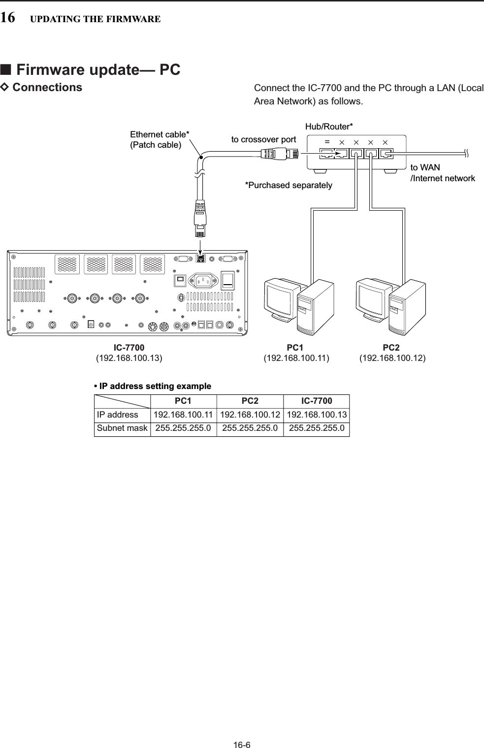
![16-7DIP address settingIMPORTANT!: A fixed (static) IP address is used forthe IC-7700.When you connect the IC-7700 to a LAN, ask thenetwork manager about a usable/assignable IPaddress and the subnet mask in advance.NEVER use an IP address that has already beenused with another device in the network. If the IPaddress is duplicated, the network will crash.qPush several times to close a multi-func-tion screen, if necessary.wPush [SET] to select set mode menu screen.ePush [OTHERS] to select Others set mode.rPush [Y] or [Z] several times to select“IP Address” item.tPush [Ω≈] to select the desired part then ro-tate the main dial to set the desired or specified IPaddress.• “192.168.0.1” is the default setting.yPush [Z] to select “Subnet Mask” item.uRotate the main dial to set the desired or specifiedsubnet mask.• “255.255.255.0” is the default setting.iPush to turn the transceiver power OFF,then ON to enable the IP address and subnet masksettings.POWERF-2F-3F-2F-1F-5F-7EXIT/SETWhen updating the firmware from the USB-Memory,the following settings are not necessary.F-2 F-3F-1Ω ≈F-5OTHERS EXIT/SETF-7SET∫ √16UPDATING THE FIRMWARE](https://usermanual.wiki/ICOM-orporated/300900.User-Manual-Part-2/User-Guide-900713-Page-101.png)
![16-8DUpdating from the PCqStart up the IC-7700 Firm Utility.• The window as at left appears.wRead the caution in the window carefully.eClick [Yes] if you agree and continue the firmwareupdating.rSelect the firmware file, that has “dat” extension(e.g.: 7700_110.dat).• Click […], then select the file, as well as the location.tType the IC-7700’s IP address into “IC-7700 IP Ad-dress” text box.yClick [Start].uThe window as at left appears.Read the precaution in the window carefully. iClick [Yes] if you want to start the firmware update.Updating the main CPU firmware first.It will take approx. 1 minute.DO NOT turn the IC-7700 power OFF until "Completed" dialog is displayed.Depending on the updated contents, the sub CPU and/or DSP firmware will automatically be updated when rebooting the IC-7700 and this will take approx. 2 minutes. DO NOT turn the IC-7700 power OFF until the normal operational screen appears, in such case.Do you wish to start the firmware update?Click to start thefirmware updateIC-7700 IP AddressVersion 1.00(C) 2007 Icom Inc.Firmware File NameTurn the IC-7700 power ON.When the normal operational screen appears, set the firmware file nameand IP address, then click [Start] button.IC-7700 Firm UtilityClick [ ] to select the firmware file.Type the IC-7700 s IP address here.Do you agree to all of the above?i7700HF/50MHz TRANSCEIVERFirm Utility===CAUTION===Updating the firmware is very risky. If you make a mistake, the IC-7700 may not operate properly, and repair at Icom Inc.(Japan) may be the only way to fix it.You undertake the updating of the firmware at you own risk and responsibility, Please refer to the firmware download homepage and/or the instruction manual for the correct procedures in updating the firmware.Also all preciously set conditions, the memory contents, etc will be lost when making a firmware update.Making a backup file of programmed contents and settings onto the USB-Memory before updating is recommended.Click tocontinue16 UPDATING THE FIRMWARE](https://usermanual.wiki/ICOM-orporated/300900.User-Manual-Part-2/User-Guide-900713-Page-102.png)
![16-9oThe screen as at left is displayed.• The following dialog appears in the IC-7700 display.RWARNING!: NEVER turn the IC-7700 powerOFF at this stage.The transceiver firmware will be corrupted.!0 Click [OK] to finish the firmware update.• The “FIRMWARE UPDATING” dialog as above disap-pears.!1 Push to turn the IC-7700 power OFF, thenON again.!2 Depending on the update, one or two dialog boxesas at left appear on the IC-7700 display in se-quence.RWARNING!: NEVER turn the IC-7700 powerOFF at this stage.The transceiver firmware will be corrupted.!3 After the dialog disappears, the firmware update iscompleted and normal operation screen appears.POWERPlease wait for 10sec.WARNING! NEVER turn power OFF.Please wait for 25sec.WARNING! NEVER turn power OFF.TRX-DSP UPDATING...SCOPE-DSP UPDATING...Firmware up dating for the main CPU is completed.The sub CPU and/or DSP firmware update will start automatically depending on the updated contents, and this will take approx. 2 minutes.Turn the IC-7700 power OFF, then ON again with [POWER] switch.After turning the power ON, the IC-7700 will work with the updated firmware.DO NOT turn the IC-7700 power OFF until the normal operational screen appears.Click [OK] to finish the firmware update.IC-7700 IP AddressIC-7700 IP AddressFirmware File NameVersion 1.00(C) 2007 Icom Inc.Firmware File NameConnecting to the IC-7700.Connected to the IC-7700.Transfer in progress...Transfer successful.Start update.Please wait a while.IC-7700 Firm Utility16UPDATING THE FIRMWARE](https://usermanual.wiki/ICOM-orporated/300900.User-Manual-Part-2/User-Guide-900713-Page-103.png)