ICOM orporated 300900 HF/50 MHz Transceiver User Manual IC 7700 ENG
ICOM Incorporated HF/50 MHz Transceiver IC 7700 ENG
Contents
- 1. User Manual Part 1
- 2. User Manual Part 2
User Manual Part 2

6-1
FUNCTIONS FOR TRANSMIT Section 6
■VOX function …………………………………………………………… 6-2
DUsing the VOX function …………………………………………… 6-2
DAdjusting the VOX function ………………………………………… 6-2
DVOX set mode ……………………………………………………… 6-2
■Break-in function ………………………………………………………… 6-3
DSemi break-in operation …………………………………………… 6-3
DFull break-in operation ……………………………………………… 6-3
■∂TX function …………………………………………………………… 6-4
D∂TX monitor function ………………………………………………… 6-4
■Monitor function ………………………………………………………… 6-4
■Transmit filter width setting (SSB only) ……………………………… 6-5
■Speech compressor (SSB only) ……………………………………… 6-5
■Split frequency operation ……………………………………………… 6-6
■Quick split function ……………………………………………………… 6-7
DSplit lock function …………………………………………………… 6-7
6-2
■VOX function
The VOX (Voice-Operated Transmission) function
switches between transmit and receive with your voice.
This function provides “hands-free” operation.
D
Using the VOX function
qSelect a phone mode (SSB, AM, FM).
wPush to turn the VOX function ON or OFF.
• “ ” appears while the VOX is in use.
• [VOX] indicator above this switch lights green.
D
Adjusting the VOX function
qSelect a phone mode (SSB, AM, FM).
wPush to turn VOX function ON.
eWhile speaking into the microphone with your nor-
mal voice level, rotate [VOX GAIN] to the point
where the transceiver is continuously transmitting.
rDuring receive, rotate [ANTI VOX] to the point
where the transceiver does not switch to transmit
due to received audio from the speaker.
tAdjust the VOX delay and the VOX voice delay in
VOX set mode, if necessary.
D
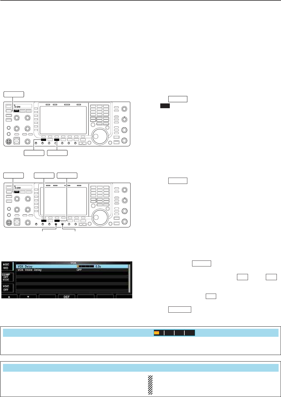
VOX set mode
qPush and hold for 1 sec. to enter VOX set
mode.
wSelect the desired item using [Y] or [Z] .
eRotate the main dial to the desired set value or con-
dition.
• Push and hold [DEF] for 1 sec. to select a default
value.
rPush to exit VOX set mode.
EXIT/SET
F-4
F-2F-1
VOX
VOX
VOX
VOX
[VOX GAIN] [ANTI VOX]
AM/FM
SSBVOX
AM/FM
SSB
VOX
6FUNCTIONS FOR TRANSMIT
Set the VOX delay for a convenient interval before re-
turning to receive within 0 to 2.0 sec. range.
VOX Delay
0.2s
Set the VOX voice delay to prevent unintended trans-
mission of your voice when switching to transmit.
Short, Mid., Long and OFF settings are available.
When using the VOX voice delay, turn the TX mon-
itor function OFF to prevent transmitted audio from
be echoed.
VOX Voice Delay
Short
6-3
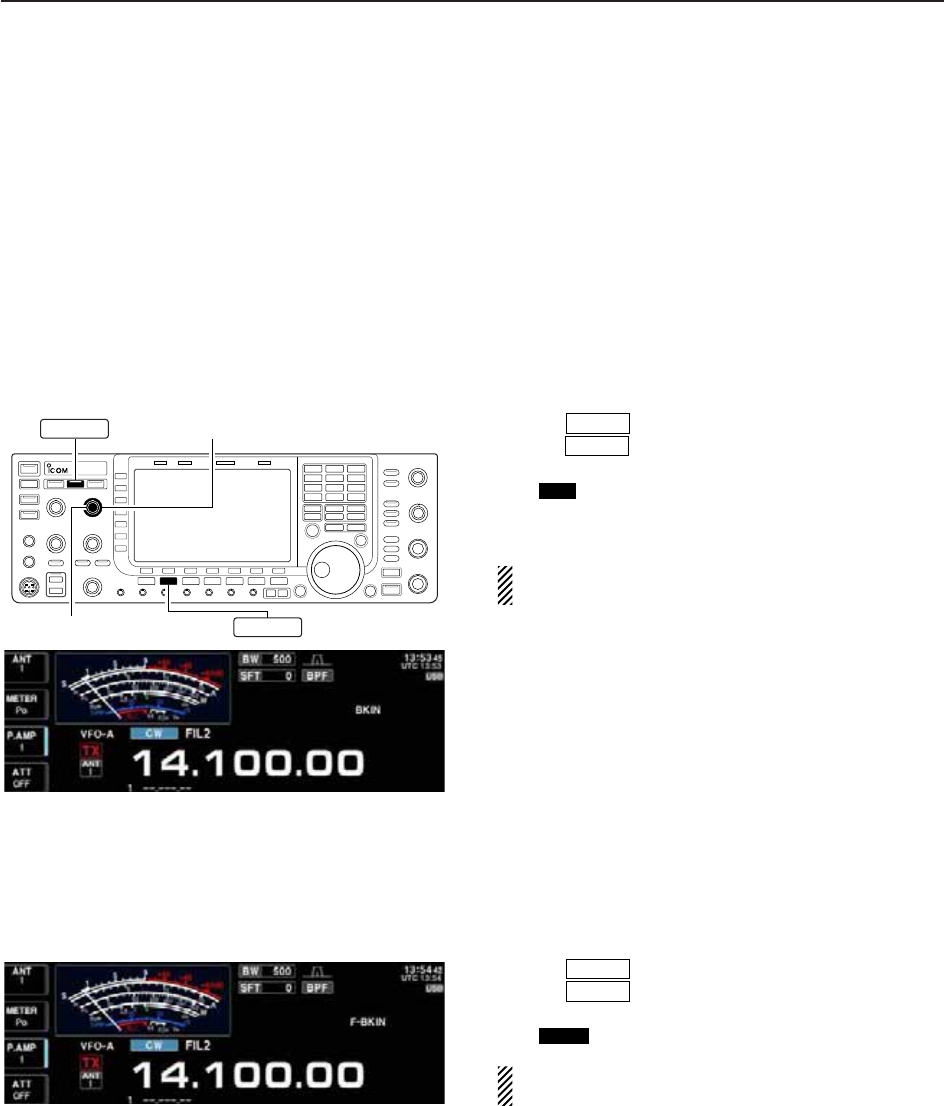
■Break-in function
The break-in function is used in CW mode to automat-
ically toggle the transceiver between transmit and re-
ceive when keying. The IC-7700 is capable of full
break-in or semi break-in.
D
Semi break-in operation
During semi break-in operation, the transceiver selects
transmit when keying, then automatically returns to re-
ceive after a pre-set time after you stop sending.
qPush to select CW or CW-R mode.
wPush once or twice to turn the semi break-in
function ON.
• “ ” appears.
eRotate [DELAY] to set the break-in delay time (the
delay from transmit to receive).
When using a paddle, rotate [KEY SPEED] to adjust
the keying speed.
D
Full break-in operation
During full break-in operation, the transceiver auto-
matically enters transmit while keying and returns to
receive immediately after keying is finished.
qPush to select CW or CW-R mode.
wPush once or twice to turn the full break-in
function ON.
• “ ” appears.
When using a paddle, rotate [KEY SPEED] to adjust
the keying speed.
F-BKIN
BK-IN
CW
BKIN
BK-IN
CW
BK-IN
CW
[DELAY] (outer control)
[KEY SPEED] (inner control)
6
FUNCTIONS FOR TRANSMIT
6-4
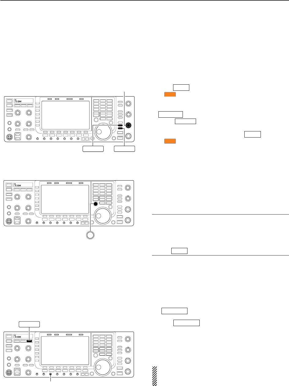
■
∂
TX function
The ∂TX function shifts the transmit frequency up to
±9.999 kHz in 1 Hz steps (10 Hz steps when cancelling
the 1 Hz step readout) without moving the receive fre-
quency.
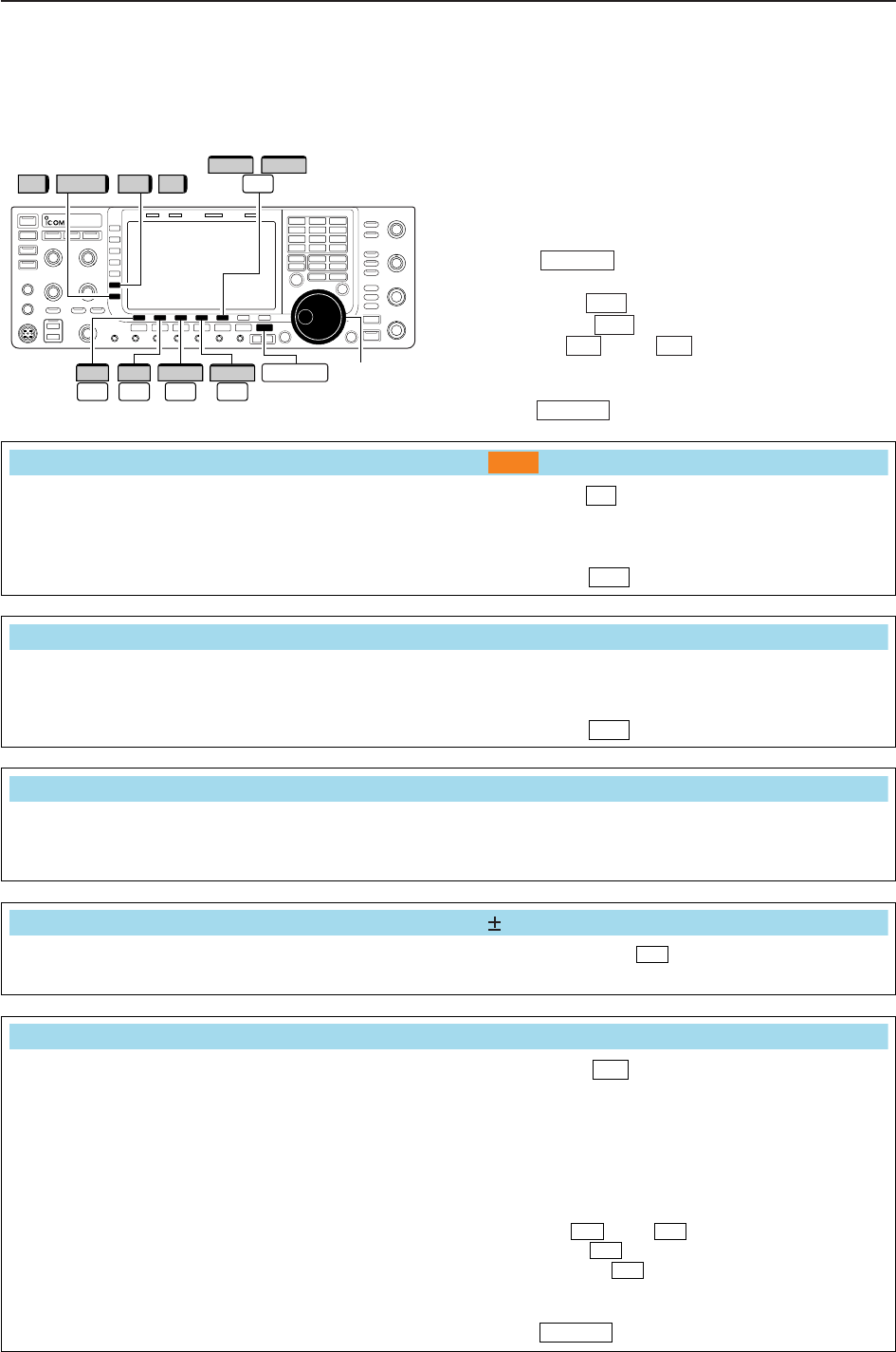
qPush .
• “ ” appears.
wRotate [RIT/∂TX].
eTo reset the ∂TX frequency, push and hold
for 1 sec.
• Push momentarily to reset the ∂TX frequency
when the quick RIT/∂TX clear function is ON. (p. 12-15)
rTo cancel the ∂TX function, push again.
• “ ” disappears.
D∂
TX monitor function
When the ∂TX function is ON, pushing and holding
[XFC] allows you to monitor the operating frequency
directly (∂TX is temporarily cancelled).
✔For your convenience— Calculate function
The shift frequency of the ∂TX function can be
added/subtracted to the displayed frequency.
➥While displaying the ∂TX shift frequency, push and
hold for 1 sec.
■Monitor function
The monitor function allows you to monitor your trans-
mit IF signals in any mode. Use this to check voice
characteristics while adjusting SSB transmit parame-
ter (p. 12-5). The CW sidetone functions regardless of
the switch setting.
qPush to switch the monitor function ON
and OFF.
• [MONITOR] indicator above this switch lights green.
wRotate [MONI GAIN] for the clearest audio output
while pushing [PTT] and speaking into the micro-
phone.
NOTE: When using the VOX voice delay, turn the
monitor function OFF; or transmitted audio will be
echoed.
MONITOR
MONITOR
∂TX
∂TX
∂TX
CLEAR
CLEAR
∂TX
∂TX
[RIT/∂TX]
∂TX CLEAR
XFC
[MONI GAIN]
MONITOR
6FUNCTIONS FOR TRANSMIT
6-5
■Transmit filter width setting (SSB only)
The transmit filter width for SSB mode can be selected
from wide, middle and narrow.
➥During USB or LSB mode selection, push and hold
[COMP] (MF6) for 1 sec. several times to select the
desired transmit filter width from wide, middle and
narrow.
• The filter can be independently set on the speech com-
pressor function is ON and OFF.
• The following filters are specified as the default. Each of
the filter width can be re-set in level set mode.
(p. 12-6)
WIDE : 100 Hz to 2.9 kHz
MID : 300 Hz to 2.7 kHz
NAR : 500 Hz to 2.5 kHz
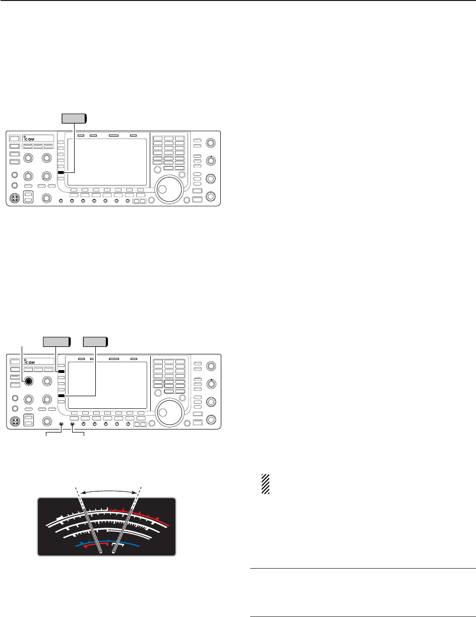
■Speech compressor (SSB only)
The speech compressor increases average RF output
power, improving signal strength and readability in
SSB mode only.
qSelect USB or LSB mode and adjust [MIC] to a suit-
able level.
• Push [METER] (MF2) several times to select the ALC
meter for microphone gain adjustment.
wPush [COMP] (MF6) to turn the speech compressor
ON.
ePush [METER] (MF2) once to select the COMP
meter.
rWhile speaking into the microphone, rotate [COMP]
control, so that the COMP meter reads within the
COMP zone (10 to 20 dB range) for your normal
voice level.
When the COMP meter peaks exceed the COMP
zone, your transmitted voice may be distorted.
tPush [METER] (MF2) 5 times to select the ALC
meter.
yWhile speaking into the microphone, rotate [DRIVE],
so that the ALC meter reads within the 30 to 50%
range of the ALC zone with your normal voice level.
✔For your convenience
Push and hold [METER] (MF2) for 1 sec. to display the
multi-function meter that can check the ALC and
COMP level at a glance.
S
1
0
0
0
1
2
510
10
10 20
44 52V
50 100 150 200 250
15
3
1.5
ID
VD
dB
WA
Po
SWR
COMP ALC
59+20 +40 +60dB
∞
COMP zone
[MIC]
[DRIVE] [COMP] control
COMPMETER
COMP
6
FUNCTIONS FOR TRANSMIT
6-6
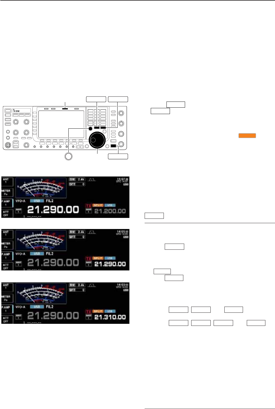
■Split frequency operation
Split frequency operation allows you to transmit and
receive in the same mode on two different frequencies.
Split frequency operation is performed using 2 fre-
quencies on the main and sub readouts.
The following is an example of setting 21.290 MHz for
receiving and 21.310 MHz for transmitting.
qSet 21.290 MHz (USB) in VFO mode.
wPush momentarily, then push and hold
for 1 sec.
• The quick split function is much more convenient for se-
lecting the transmit frequency. See the next section for
details.
• The equalized transmit frequency and “ ” appear
on the LCD.
• [SPLIT] indicator lights.
• “TX” appears to show the transmit frequency readout.
eSet the transmit frequency to 21.310 MHz in the fol-
lowing way.
➥Rotate the main dial while pushing [XFC].
• The transmit frequency can be monitored while push-
ing [XFC].
rNow you can receive on 21.290 MHz and transmit
on 21.310 MHz.
To change the transmit and receive frequencies, push
to exchange the main and sub readouts.
✔
CONVENIENT
• Direct shift frequency input
The shift frequency can be entered directly.
qPush .
wEnter the desired shift frequency with the digit keys.
• 1 kHz to 1 MHz can be set.
• When you require a negative shift direction, push
in advance.
ePush .
• The shift frequency is input in the sub readout and the
split function is turned ON.
[Example]
To transmit on 1 kHz higher frequency:
- Push , then .
To transmit on 3 kHz lower frequency:
- Push , , then .
• Split lock function
Accidentally releasing [XFC] while rotating the main
dial changes the receive frequency. To prevent this,
use both the split lock and dial lock functions to change
the transmit frequency only. The split lock function can-
cels the dial lock function while pushing [XFC] during
split frequency operation.
The dial lock’s effect during split frequency operation
can be selected in the set mode for both receive and
transmit frequencies; or only the receive frequency.
(p. 12-13)
SPLIT
73
GENE •
F-INPENT
SPLIT
1.8 1
F-INPENT
SPLIT
GENE •
F-INPENT
A/B
SPLIT
A=B
SPLIT
Main dial
[SPLIT] indicator
SPLIT
A/B A=B
XFC
6FUNCTIONS FOR TRANSMIT
• When the split function ON
• When [XFC] is pushed
• The split frequency operation is ready
6-7
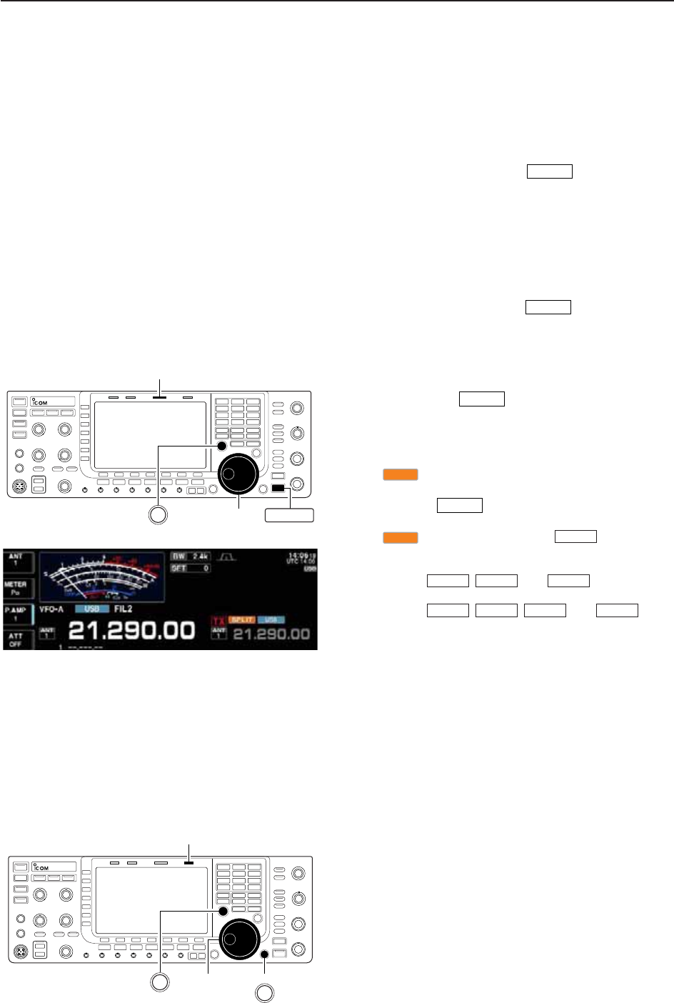
■Quick split function
When you find a DX station, an important considera-
tion is how to set the split frequency.
When you push and hold the switch for 1 sec.,
split frequency operation is turned ON and the trans-
mit frequency is equalized to the received frequency.
This shortens the time needed to begin split frequency
operation.
The quick split function is ON by default. For your con-
venience, it can be turned OFF in Others set mode.
(p. 12-12) In this case, the switch does not
equalize the transmit frequency to the receive fre-
quency.
qSuppose you are operating at 21.290 MHz (USB) in
VFO mode.
wPush and hold for 1 sec.
• Split frequency operation is turned ON.
• The transmit frequency (unselected VFO’s readout) is
equalized to the receive frequency (selected VFO’s read-
out).
• “ ” indicator appears.
eEnter the desired offset frequency from the keypad
then push , or set the transmit frequency
with the main dial while pushing [XFC].
• “ ” indicator appears when is pushed.
• Offset frequency setting with the keypad— example
To transmit on 1 kHz higher frequency:
- Push , then .
To transmit on 3 kHz lower frequency:
- Push , , then .
D
Split lock function
The split lock function is convenient for changing only
the transmit frequency. When the split lock function is
not used, accidentally releasing [XFC] while rotating
the main dial, changes the receive frequency. The split
lock function is ON by default, but can be turned OFF
in set mode. (p. 12-13)
qWhile split frequency operation is ON, push [LOCK]
to activate the split lock function.
wWhile pushing [XFC], rotate the main dial to change
the transmit frequency.
• If you accidentally release [XFC] while rotating the main
dial, the receive frequency does NOT change.
SPLIT
73
GENE •
F-INPENT
SPLIT
1.8 1
F-INPENT
F-INPENT
F-INP
SPLIT
F-INP
SPLIT
SPLIT
SPLIT
Main dial
[SPLIT] indicator
SPLIT
XFC
Main dial
[LOCK] indicator
XFC
LOCK
6
FUNCTIONS FOR TRANSMIT

7-1
VOICE RECORDER FUNCTIONS Section 7
■About digital voice recorder …………………………………………… 7-2
■Recording a received audio …………………………………………… 7-3
DBasic recording ……………………………………………………… 7-3
DOne-touch recording ………………………………………………… 7-3
■Playing the recorded audio …………………………………………… 7-4
DBasic playing ………………………………………………………… 7-4
DOne-touch playing …………………………………………………… 7-4
■Protect the recorded contents ………………………………………… 7-5
■Erasing the recorded contents ………………………………………… 7-5
■Recording a message for transmit …………………………………… 7-6
DRecording …………………………………………………………… 7-6
DConfirming a message for transmit ………………………………… 7-6
■Programming a memory name ……………………………………… 7-7
■Sending a recorded message ………………………………………… 7-8
DTransmit level setting ……………………………………………… 7-8
■Voice set mode ………………………………………………………… 7-9
■Saving a voice message into the USB-Memory …………………… 7-10
DSaving the received audio memory ……………………………… 7-10
DSaving the TX memory …………………………………………… 7-10
7-2
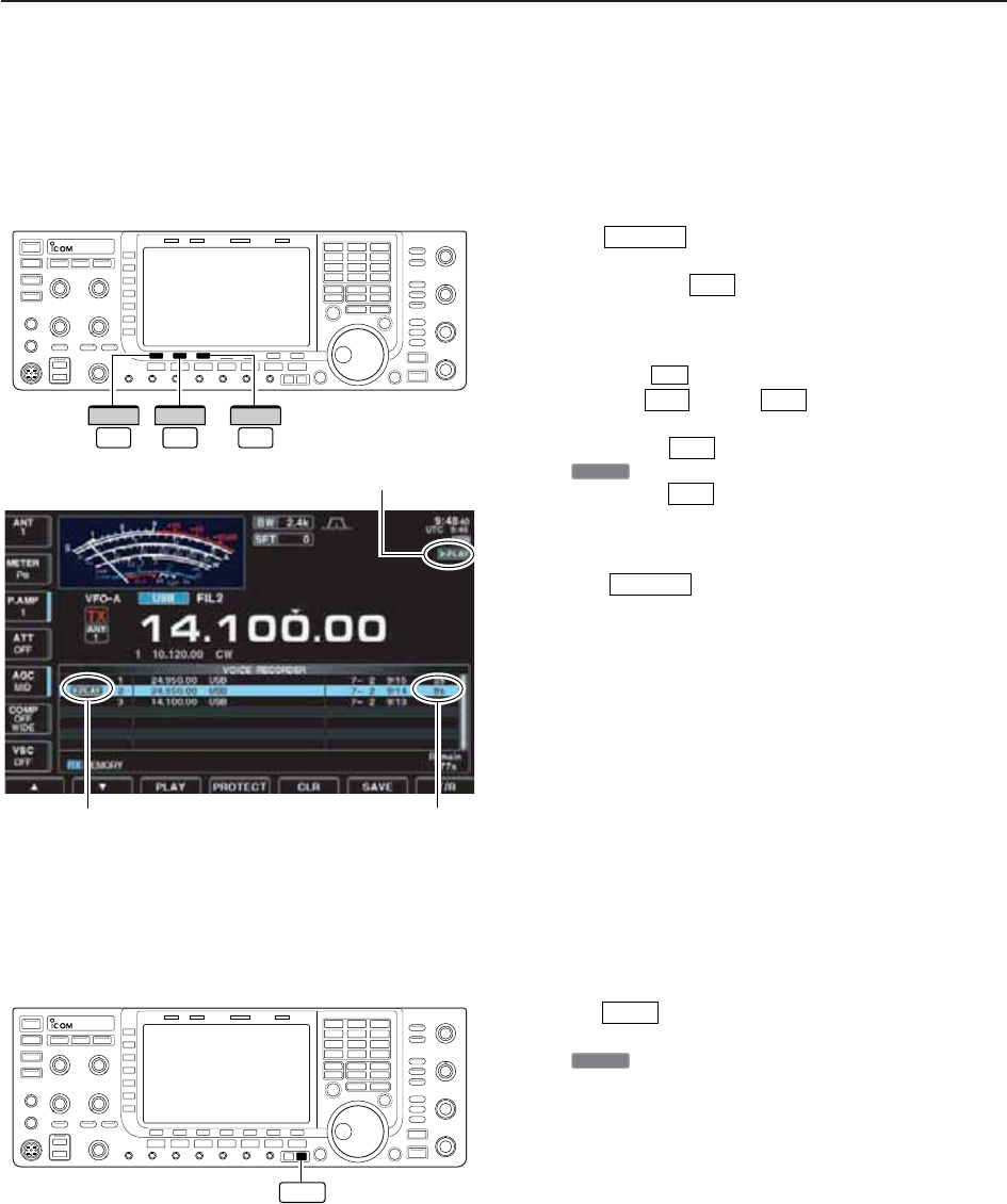
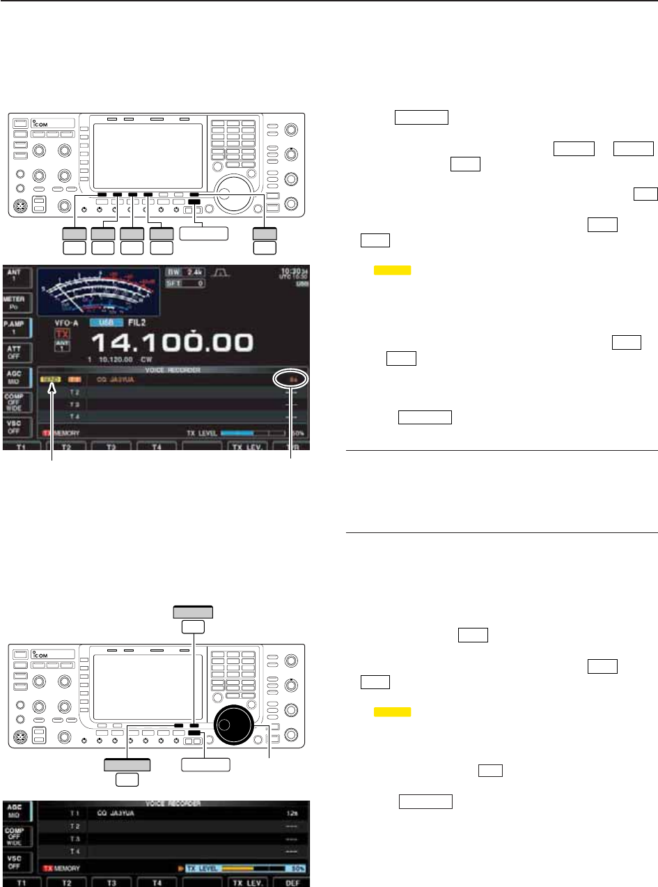
■About digital voice recorder
The IC-7700 has digital voice memories, up to 4 mes-
sages for transmit, and up to 20 messages for receive.
A maximum message length of 30 sec. can be
recorded into receive memory (total message length
for all channels of up to 209 sec.) and a total message
length of up to 99 sec. can be recorded in transmit
memory.
The transmit memory is very convenient for repeated
CQ and exchange transmissions in contests, as well
as when making consecutive calls to DXpeditions.
qSelect any mode.
wPush [VOICE] to display voice recorder screen.
ePush to display voice recorder menu.
rPush [PLAY] or [MIC REC] to select the
desired memory channel screen, then record audio
or playback the contents as described below.
tPush twice to exit voice recorder screen.
EXIT/SET
F-2F-1
EXIT/SET
F-2
EXIT/SETREC PLAYF-1 F-2
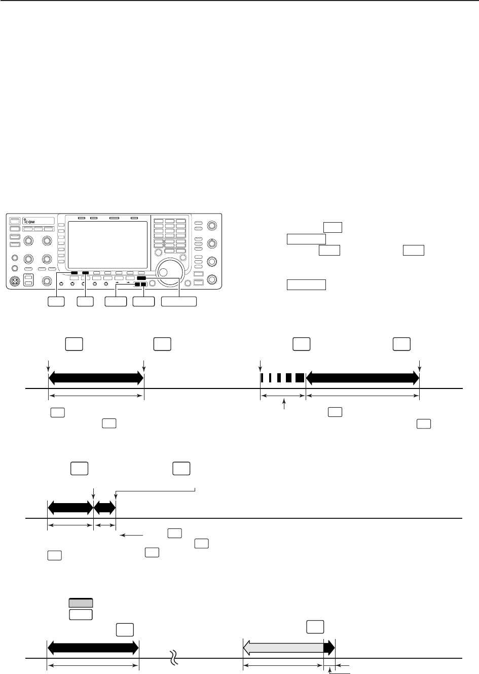
• Example— When [REC] is pushed and held for 1sec.
• Example— When [REC] is pushed momentarily
• Playing back the all contents in a channel • Playing back the end of 5 sec.* in a channel
20 sec.
15 sec.
(default)
30 sec. (max.) Not playing back Play back (5 sec.; default)
3 sec.
30 sec.
Push momentarily within 30 sec. after
pushing and holding for 1 sec., records
the all contents.
Push momentarily re-
cords the contents of the
previous 15 sec.*
When is pushed momentarily again within 15 sec.*
from the last operation, all the contents between
operations will be recorded.
Push momentarily after passing 30
sec. from pushing and holding for
1 sec., records the 30 sec. before can-
celing the record.
These contents
won’t be recorded.
*The recording time period can be changed with “Normal Rec Time” in voice set mode (p. 7-9).
*The playing back time period can be changed with
“Short Play Time” in voice set mode (p. 7-9).
NOTE: The contents will be recorded into an independent memory
channels automatically.
REC
REC
REC
REC
REC
REC
REC
REC
Push and hold for 1 sec.
(starts recording)
REC
Push momentarily
(starts recording)
REC
Push momentarily
(starts recording)
REC
Push momentarily
(stops recording)
REC
Push and hold for 1 sec.
(starts recording)
REC
Push momentarily
(stops recording)
REC
Push momentarily.
PLAY
Or, push and hold for 1 sec.
PLAY
Push momentarily.
F-2
PLAY
7VOICE RECORDER FUNCTIONS
7-3
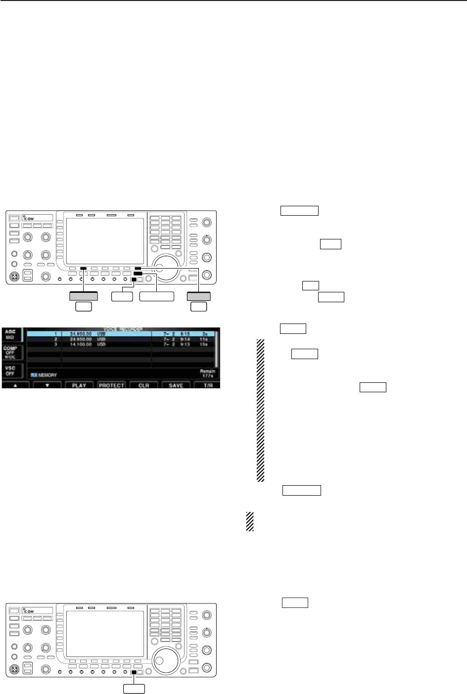
■Recording a received audio
Up to 20 receive voice memories are available in the
IC-7700. A total audio length of up to 209 sec. can be
recorded in receive messages. However, the maximum
recordable length into a single message is 30 sec.
This voice recorder records not only the received
audio, but also the information such as set operating
frequency, mode, and the recording time for your fu-
ture reference.
D
Basic recording
qPush several times to close a multi-func-
tion screen, if necessary.
wSelect the desired mode.
ePush [VOICE] to call up the voice recorder
screen.
• Previously selected screen, TX or RX memory, is dis-
played. If the TX memory channel (T1–T4) appears,
push [T/R] to select RX memory channel.
rPush and hold for 1 sec. to start recording.
• The operating frequency, mode and current time are pro-
grammed as the memory names automatically.
tPush momentarily to stop recording.
IMPORTANT!
Push to stop recording before, or when
30 sec. has passed from the start of recording.
The voice recorder memory records the 30 sec.
(max.) of audio before is pushed.
For example, when recording 40 sec. of audio,
the first 10 sec. audio will be over-written with the
last 10 sec., so that the total of audio recorded is
only 30 sec.
When you record the 21st audio message, or
when the total audio length exceeds 209 sec., the
oldest recorded audio is automatically erased to
make room for the new audio.
yPush twice to exit the voice recorder
screen.
NOTE: When transmit (or [PTT] is pushed) while
recording, no audio will be recorded.
D
One-touch recording
To record the received signal immediately, one-touch
voice recording is available.
➥Push momentarily to record the previous
15 sec. audio.
• The recordable time period can be set in voice set mode.
(p. 7-9)
REC
EXIT/SET
REC
REC
REC
REC
F-7
F-2
EXIT/SET
EXIT/SET
REC
F-7
T/R
F-2
VOICE
REC
7
VOICE RECORDER FUNCTIONS
7-4
■Playing the recorded audio
D
Basic playing
qPush several times to close a multi-func-
tion screen, if necessary.
wPush [VOICE] to call up the voice recorder
screen.
• Previously selected screen, TX or RX memory, is dis-
played. If the TX memory message (T1–T4) appears,
push [T/R] to select RX memory message.
ePush [Y] or [Z] to select the desired
voice memory to playback.
rPush [PLAY] to start playback.
• “ ” indicators appear and the timer counts down.
tPush [PLAY] again to stop playback if desired.
• Playback is terminated automatically when all of the
recorded contents in the message are played, or after
30 sec.
yPush twice to exit the voice recorder
screen.
D
One-touch playing
The previously recorded audio in message 1 can be
played back without selecting voice recorder screen.
➥Push momentarily to play back the last 5 sec.
of the previously recorded audio.
• “ ” indicator appears.
• Playback is terminated automatically when all of the
recorded contents in the message are played, or after
5 sec.
• The playback time period can be set in voice set mode.
(p. 7-9)
≈PLAY
PLAY
EXIT/SET
F-3
≈PLAY
F-3
F-2F-1
F-7
F-2
EXIT/SET
F-3
PLAY
F-1
∫
F-2
√
Appears
Appears
Counts down
PLAY
7VOICE RECORDER FUNCTIONS
7-5
■Protect the recorded contents
The protect function is available to protect the recorded
contents from accidental erasure, such as over-writing,
etc.
qCall up the voice recorder screen, RX memory.
wPush [Y] or [Z] to select the desired
voice message.
ePush [PROTECT] to turn the protect function
ON and OFF.
• “ ” indicator appears when the contents is protected.
rPush twice to exit the voice recorder
screen.
■Erasing the recorded contents
The recorded contents can be erased independently
by message.
qCall up the voice recorder screen, RX memory.
wPush [Y] or [Z] to select the desired
voice message to be erased.
ePush and hold [CLR] for 1 sec. to erase the
contents.
• Push [PROTECT] to release the protection in ad-
vance if necessary.
rPush twice to exit the voice recorder
screen.
EXIT/SET
F-4
F-5
F-2F-1
EXIT/SET
F-4
F-2F-1
F-4
PROTECT
F-1
∫
F-2
√
F-5
CLR
F-1
∫
F-2
√
7
VOICE RECORDER FUNCTIONS
7-6
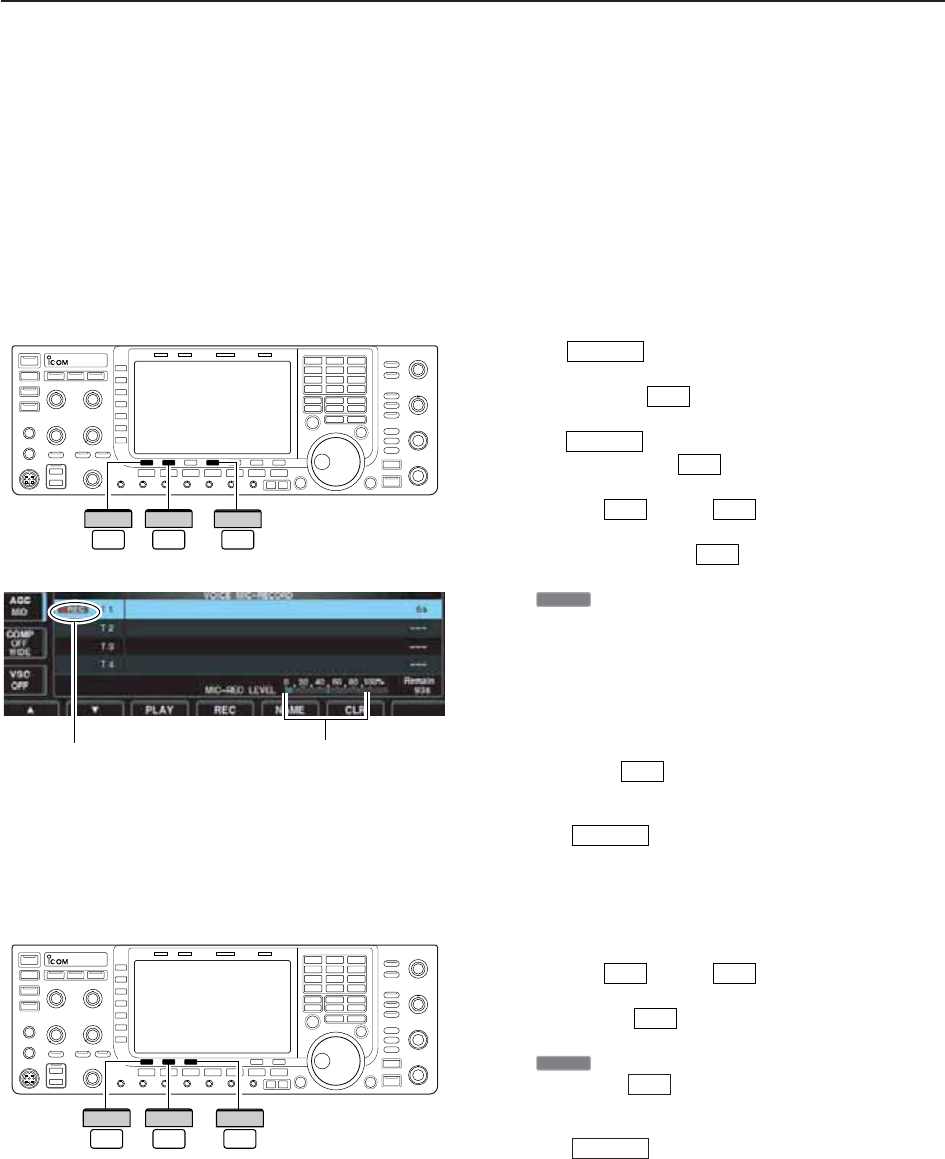
■Recording a message for transmit
To transmit a message using the voice recorder, record
the desired message in advance as described below.
The IC-7700 has digital voice memories for transmis-
sion, up to 4 messages and a total message length of
up to 99 sec. can be recorded.
D
Recording
qPush several times to close a multi-func-
tion screen, if necessary.
wPush [VOICE] to call up the voice recorder
screen.
ePush to select voice recorder menu.
rPush [MIC REC] to select the voice mic.
record screen.
tPush [Y]or[Z] to select the desired
message.
yPush and hold [REC] for 1 sec. to start record-
ing.
• “ ” indicator appears.
• Speak into the microphone without pushing [PTT].
• Previously recorded contents are cleared.
• Audio output from the internal speaker is automatically
muted.
uWhile speaking into the microphone with your nor-
mal voice level, adjust the [MIC] control so that the
[MIC-REC LEVEL] indicator reads within 100%.
iPush [REC] momentarily to stop recording.
• The recording is terminated automatically when the re-
maining time becomes 0 sec.
oPush twice to exit the voice recorder
screen.
D
Confirming a message for transmit
qPerform the steps qto ras “DRecording” above.
wPush [Y]or[Z] to select the desired
message.
ePush [PLAY] to playback the recorded con-
tents.
• “ ” indicator appears.
rPush [PLAY] again to stop playback.
• Playback is terminated automatically when all of the
recorded contents in the message are played.
tPush twice to exit the voice recorder
screen.
EXIT/SET
F-3
≈PLAY
F-3
F-2F-1
EXIT/SET
F-4
●REC
F-4
F-2F-1
F-2
EXIT/SET
F-2
EXIT/SET
F-4
REC
F-1
∫
F-2
√
Appears Adjust [MIC] control so that this
indicator reads within 100%.
F-3
PLAY
F-1
∫
F-2
√
7VOICE RECORDER FUNCTIONS
7-7
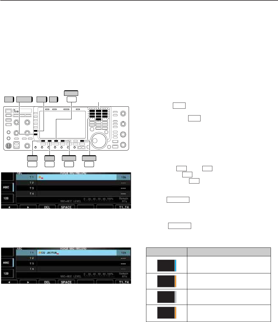
■Programming a memory name
Memory messages can be tagged with alphanumeric
names of up to 20 characters each.
Capital letters, small letters, numerals, some symbols
(! # $ % & ¥ ? “ ‘ ` ^ + – ✱/ . , : ; = < > ( ) [ ] { } | _ ~@)
and spaces can be used. (See the table below.)
qRecord a message as described in page 7-6.
wDuring the voice mic. record screen indication, push
[NAME] to enter memory name edit condition.
• A cursor appears and blinks.
ePush [T1..T4] several times to select the de-
sired voice message.
rInput the desired character by rotating the main dial
or by pushing the band key for number input.
• Push [ABC] (MF6) or [abc] (MF6) to toggle capital and
small letters.
• Push [123] (MF7) or [Symbol] (MF7) to toggle numerals
and symbols.
• Push [Ω] or [≈] for cursor movement.
• Push [DEL] to delete the selected character.
• Push [SPACE] to input a space.
• Pushing the transceiver’s keypad, [0]–[9], can also enter
numerals.
tPush to input and set the name.
• The cursor disappears.
yRepeat steps eto tto program another voice
message’s name, if desired.
uPush twice to exit the voice recorder
screen.
• Voice memory name editing example • Usable characters
EXIT/SET
EXIT/SET
F-4
F-3
F-2F-1
F-7
F-5
Keypad
T1..T4
F-7
//
F-3
DEL
123 Symbol ABC abc
F-1
Ω
F-2
≈
F-4
SPACE
7
VOICE RECORDER FUNCTIONS
Key selection Editable characters
A to Z (capital letters)
a to z (small letters)
0 to 9 (numbers)
! # $ % & ¥ ? “ ‘ ` ^ + – ✱/ . , : ; =
< > ( ) [ ] { } | _ ~@
Symbol
123
abc
ABC
7-8
■Sending a recorded message
qPush several times to close a multi-func-
tion screen, if necessary.
wSelect a phone mode by pushing or .
ePush [VOICE] to call up the voice recorder
screen.
• If the receive voice message appears, push [T/R]
to select TX message (T1–T4).
rPush the desired message switch, [T1] to [T4]
, momentarily to transmit the contents.
• The transceiver transmits automatically.
• “ ” indicator appears and the memory timer
counts down.
• You hear the transmitted message from the speaker as
the default. This can be turned OFF in voice set mode.
(p. 7-9)
tPush the selected message switch, [T1] to
[T4] , again to stop, if desired.
• The transceiver returns to receive automatically when all
of the recorded contents in the message are transmit-
ted.
yPush twice to exit the voice memory
screen.
✔
For your information
When an external keypad is connected to [EXT KEY-
PAD], the recorded message, T1–T4, can be transmit-
ted without opening the voice recorder screen.
See page 2-7 for details.
D
Transmit level setting
qCall up the voice recorder screen as described as
above.
wPush [TX LEV.] to select the voice memory
transmit level set condition.
ePush the desired message switch, [T1] to [T4]
, momentarily to transmit the contents.
• The transceiver transmits automatically.
• “ ” indicator appears and the memory timer
counts down.
rRotate the main dial to adjust the transmit voice
level.
• Push and hold [DEF] for 1 sec. to select the default
condition.
tPush to return to the voice recorder
screen.
EXIT/SET
F-7
SEND
F-4
F-1
F-6
EXIT/SET
F-4
F-1
SEND
F-4
F-1
F-7
F-2
AM/FMSSB
EXIT/SET
F-1
T1
F-2
T2
F-3
T3
F-4
T4
F-7
T/R
EXIT/SET
Appears Counts down
Main dial
EXIT/SET
F-6
TX LEV.
F-7
DEF
7VOICE RECORDER FUNCTIONS
7-9
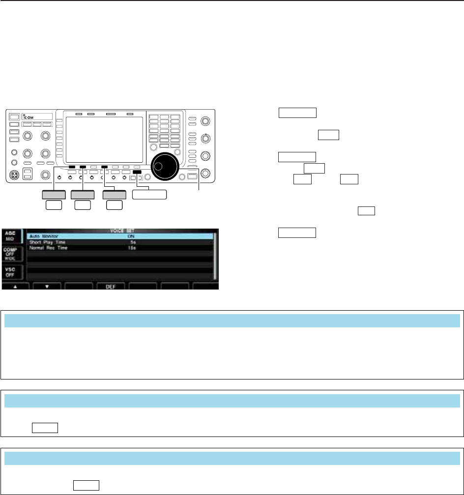
■Voice set mode
Sets the automatic monitor function, short play and
normal recording times for voice recorder.
qPush several times to close a multi-func-
tion screen, if necessary.
wPush [VOICE] to call up the voice recorder
screen.
ePush to select voice recorder menu.
rPush [SET] to select voice set mode screen.
tPush [Y] or [Z] to select the desired item.
yRotate the main dial to set the desired condition or
value.
• Push and hold [F-4•DEF] for 1 sec. to select the
default condition or value.
uPush to exit the voice set mode screen.
EXIT/SET
F-4
F-2F-1
F-7
EXIT/SET
F-2
EXIT/SET
Main dial
F-4
DEF
F-1
∫
F-2
√EXIT/SET
7
VOICE RECORDER FUNCTIONS
Turn the automatic monitor function for recorded
audio contents transmission.
• ON : Monitors transmitting audio automatically
when sending a recorded audio.
• OFF : Monitors transmitting audio only when the
monitor function is in use.
Auto Monitor
ON
Set the desired time period for the one-touch playing
(when is pushed momentarily).
• 3 to 10 sec. in 1 sec. steps can be set.
(default: 5 sec.)
PLAY
Short Play Time
5s
Set the desired time period for the for one-touch
recording (when is pushed momentarily).
• 5 to 15 sec. in 1 sec. steps can be set.
(default: 15 sec.)
REC
Normal Rec Time
15s
7-10
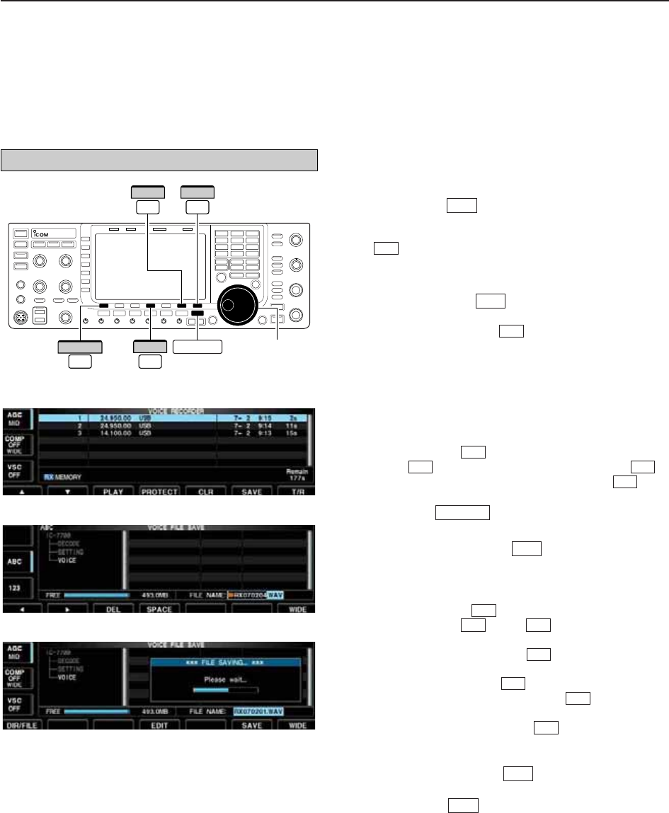
■Saving a voice message into the USB-Memory
D
Saving the received audio memory
The recorded RX memory contents can be saved into
the USB-Memory.
qDuring voice recorder RX memory screen display,
push [SAVE] to select voice file save screen.
• Previously selected screen, TX or RX memory, is dis-
played. If the TX message (T1–T4) appears, push [T/R]
to select RX message.
wChange the following conditions if desired.
• File name:
zPush [EDIT] to select file name edit con-
dition.
• Push [DIR/FILE] several times to select the
file name, if necessary.
xPush [ABC] (MF6), [123] (MF7) or [Symbol]
(MF7) to select the character group, then ro-
tate the main dial to select the character.
• [ABC] (MF6) : A to Z (capital letters); [123] (MF7): 0
to 9 (numerals); [Symbol] (MF7): ! # $ % & ‘ ` ^ + –
= ( ) [ ] { } _ ~@ can be selected.
• Push [Ω] to move the cursor left, push [≈]
to move the cursor right, push [DEL] to
delete a character and push [SPACE] to in-
sert a space.
cPush to set the file name.
• Saving location
zPush [DIR/FILE] to select tree view
screen.
xSelect the desired directory or folder in the
USB-Memory.
• Push [Ω≈] to select the upper directory.
• Push [Y] or [Z] to select folder in the
same directory.
• Push and hold [Ω≈] for 1 sec. to select a
folder in the directory.
• Push [REN/DEL] to rename the folder.
• Push and hold [REN/DEL] for 1 sec. to
delete the folder.
• Push and hold [MAKE] for 1 sec. to making
a new folder. (Edit the name with the same man-
ner as the “• File name” above.)
cPush [DIR/FILE] twice to select the file
name.
ePush [SAVE] .
• After the saving is completed, return to voice recorder
RX memory screen automatically.
D
Saving the TX memory
The TX memory contents can also be saved into the
USB-Memory. However, the contents are saved with
the message list, set mode conditions, etc. at the same
time. See page 12-22 for details.
F-6
F-1
F-6
F-5
F-5
F-4
F-3F-2
F-4
F-1
EXIT/SET
F-4
F-3F-2
F-1
F-1
F-4
F-7
F-6
Main dial
DIR/FILE EXIT/SET
F-1
F-7
WIDE
F-6
SAVE
F-4
EDIT
7VOICE RECORDER FUNCTIONS
• Voice recorder RX memory screen
• Voice file save screen— file name edit
• While saving
The USB-Memory is not supplied by Icom.

8-1
MEMORY OPERATION Section 8
■Memory channels ……………………………………………………… 8-2
■Memory channel selection …………………………………………… 8-2
DUsing the / keys ………………………………………… 8-2
DUsing the keypad …………………………………………………… 8-2
■Memory channel programming ……………………………………… 8-3
DProgramming in VFO mode ………………………………………… 8-3
DProgramming in memory mode …………………………………… 8-3
■Frequency transferring ………………………………………………… 8-4
DTransferring in VFO mode ………………………………………… 8-4
DTransferring in memory mode ……………………………………… 8-4
■Memory list screen ……………………………………………………… 8-5
DSelecting a memory channel using the memory list screen …… 8-5
DConfirming programmed memory channels ……………………… 8-5
■Memory names ………………………………………………………… 8-6
DEditing (programming) memory names …………………………… 8-6
■Memory clearing ………………………………………………………… 8-6
■Memo pads ……………………………………………………………… 8-7
DWriting frequencies and operating modes into memo pads …… 8-7
DCalling up a frequency from a memo pad ………………………… 8-7
√
∫
8-2
■Memory channels
The transceiver has 101 memory channels. Memory
mode is very useful for quickly changing to often-used
frequencies.
All 101 memory channels are tunable which means the
programmed frequency can be tuned temporarily with
the main dial, etc. in memory mode.
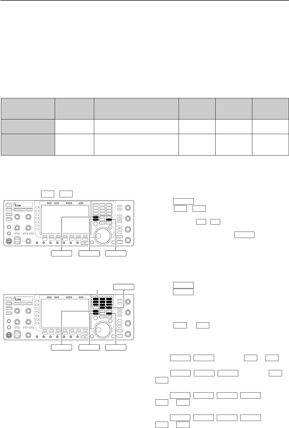
■Memory channel selection
D
Using the / keys
qPush to select memory mode.
wPush / several times to select the de-
sired memory channel.
• Push and hold / for continuous selection.
• [UP] and [DN] on the microphone can also be used.
eTo return to VFO mode, push again.
D
Using the keypad
qPush to select memory mode.
wPush .
ePush the desired memory channel number using the
keypad.
• Enter 100 or 101 to select scan edge channel P1 or P2,
respectively.
rPush or to select the desired memory
channel.
[EXAMPLE]
To select the memory channel 3;
- Push , , then push or .
To select the memory channel 12;
- Push , , , then push or
.
To select the scan edge channel P1;
- Push , , , , then push
or .
To select the scan edge channel P2;
- Push , , , , then push
or .
√
∫
1.8 1
50 0
1.8 1
F-INPENT
√
∫
50 0
50 0
1.8 1
F-INPENT
√
∫
3.5 2
1.8 1
F-INPENT
√
∫
73
F-INPENT
√
∫
F-INPENT
V/M
V/M
√
∫
√
∫
V/M
√
∫
V/M
Y Z
Keypad F-IMP ENT
V/M
Y Z
8MEMORY OPERATION
MEMORY MEMORY TRANSFER OVER-
CHANNEL CHANNEL CAPABILITY TO VFO WRITING CLEAR
NUMBER
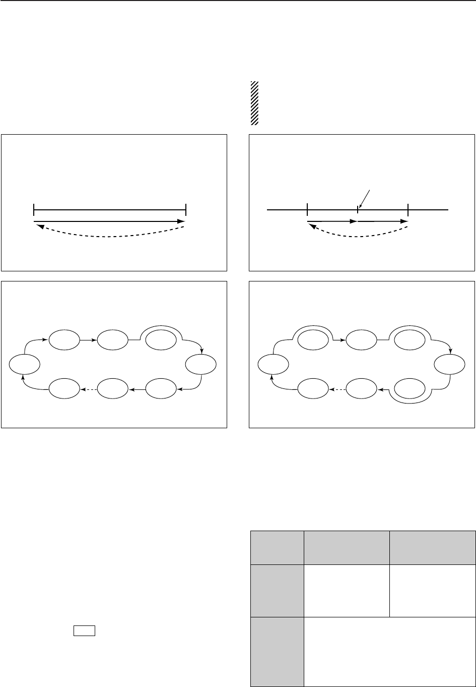
Regular memory 1–99 One frequency and one mode Yes Yes Yes
channels in each memory channel.
Scan edge
One frequency and one mode in
memory P1, P2 each memory channel as scan Yes Yes No
channels edges for programmed scan.
8-3
8
MEMORY OPERATION
■Memory channel programming
Memory channel programming can be preformed ei-
ther in VFO mode or in memory mode.
D
Programming in VFO mode
qSet the desired frequency, operating mode and fil-
ter width in VFO mode.
wPush / several times to select the de-
sired memory channel.
• Memory list screen is convenient for selecting the de-
sired channel.
• Memory channel contents appear in the memory chan-
nel readout (below the frequency readout).
• “--.---.--” appears if the selected memory channel is a
blank channel (and does not have contents).
ePush and hold for 1 sec. to program the
displayed frequency, operating mode, etc., into the
memory channel.
D
Programming in memory mode
qSelect the desired memory channel with /
in memory mode.
• Memory channel contents appear in the memory chan-
nel readout (below the frequency readout).
• “--.---.--” appears if the selected memory channel is a
blank channel (and does not have contents).
wSet the desired frequency and operating mode in
memory mode.
• To program a blank channel, use direct frequency entry
with the keypad or memo pads, etc.
ePush and hold for 1 sec. to program the
displayed frequency and operating mode into the
memory channel.
MW
√
∫
MW
√
∫
MW
Y Z
or
Push for 1 sec.
Beep
Beep
Beep
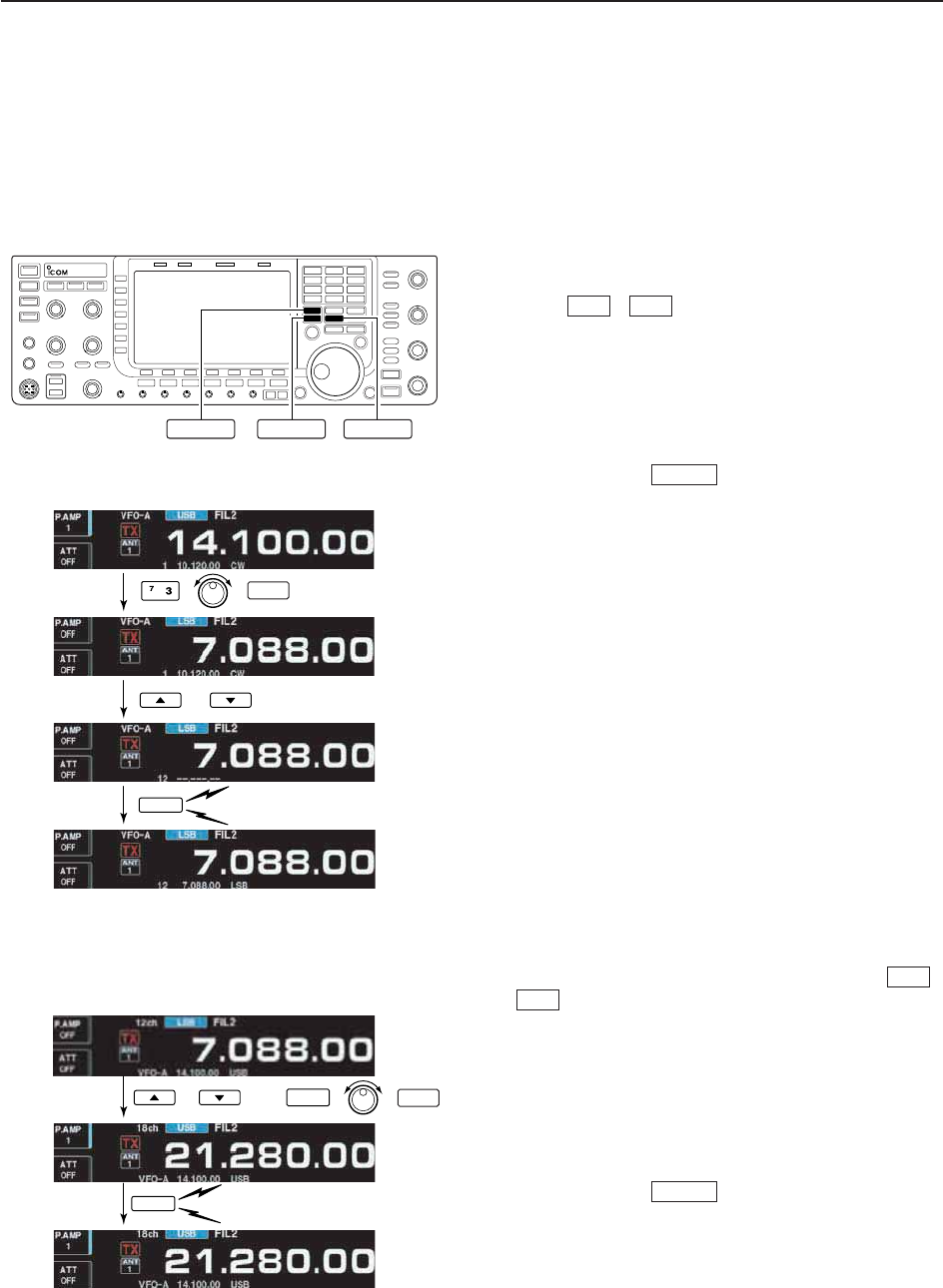
MW
SSB
[EXAMPLE]:
Programming 7.088 MHz/LSB into memory channel 12.
or then
Push for 1 sec.
Beep
Beep
Beep
7
21
MW
SSB
[EXAMPLE]:
Programming 21.280 MHz/USB into memory channel 18.
■Frequency transferring
The frequency and operating mode in a memory chan-
nel can be transferred to the VFO. Frequency transfer-
ring can be performed in either VFO mode or memory
mode.
D
Transferring in VFO mode
This is useful for transferring programmed contents to
a VFO.
qSelect VFO mode with .
wSelect the memory channel to be transferred with
/ .
• Memory list screen is convenient for selecting the de-
sired channel.
• Memory channel contents appear in the memory chan-
nel readout (below the frequency readout).
• “--.---.--” appears if the selected memory channel is a
blank channel. In this case transferring is not possible.
ePush and hold for 1 sec. to transfer the fre-
quency and operating mode.
• Transferred frequency and operating mode appear on
the frequency readout.
D
Transferring in memory mode
This is useful for transferring frequency and operating
mode while operating in memory mode.
When you have changed the frequency or operat-
ing mode in the selected memory channel:
•Displayed frequency, mode and filter setting are
transferred.
•Programmed frequency and mode in the memory
channel are not transferred, and they remain in the
memory channel.
qSelect the memory channel to be transferred with
/ in memory mode.
• And, set the frequency or operating mode if required.
wPush and hold for 1 sec. to transfer the fre-
quency and operating mode.
• Displayed frequency and operating mode are transferred
to the VFO.
eTo return to VFO mode, push momentarily.
V/M
V/M
√
∫
V/M
√
∫
V/M
8-4
8MEMORY OPERATION
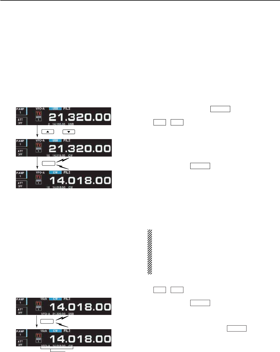
TRANSFERRING EXAMPLE IN VFO MODE
Operating frequency : 21.320 MHz/USB (VFO)
Contents of M-ch 16 : 14.018 MHz/CW
TRANSFERRING EXAMPLE IN MEMORY MODE
Operating frequency : 21.320 MHz/USB (M-ch 16)
Contents of M-ch 16 : 14.018 MHz/CW
or
Push for 1 sec.
Beep
Beep
Beep
V/M
Push for 1 sec.
Beep
Beep
Beep
Programmed contents appear.
V/M
8-5
8
MEMORY OPERATION
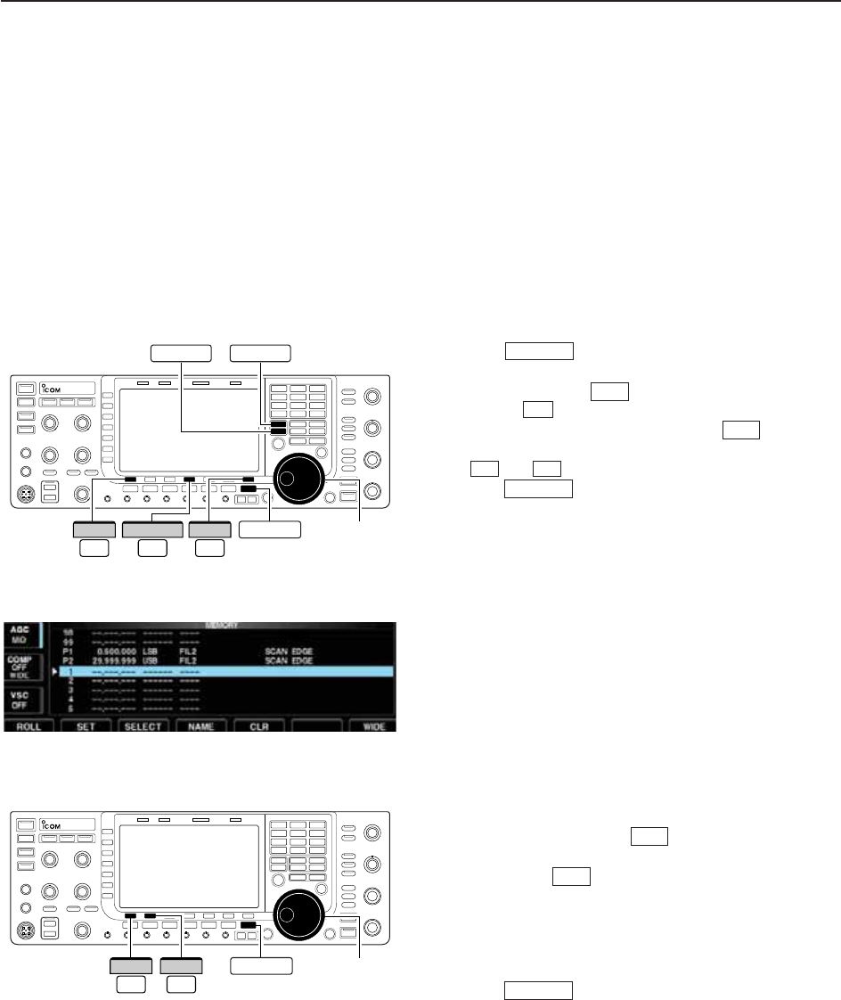
■Memory list screen
The memory list screen simultaneously shows 9 mem-
ory channels and their programmed contents. 15 mem-
ory channels can be displayed in the wide memory list
screen.
You can select a desired memory channel from the
memory list screen.
D
Selecting a memory channel using the memory list screen
qPush several times to close a multi-func-
tion screen, if necessary.
wPush [MEMORY] to select memory list screen.
• [WIDE] switches the standard and wide screens.
eWhile pushing and holding [ROLL] , rotate the
main dial to select the desired memory channel.
• and can also be used.
rPush to exit memory list screen.
• Memory list screen
D
Confirming programmed memory channels
qSelect memory list screen as described above.
wWhile pushing [ROLL] , rotate the main dial to
scroll the screen.
ePush [SET] to select the highlighted memory
channel, if desired.
•“≈” appears beside the selected memory channel num-
ber in the memory list screen and the selected memory
channel contents are displayed below the frequency
readout.
rPush to exit memory list screen.
EXIT/SET
F-2
F-1
EXIT/SET
√
∫
F-1
F-7
F-4
EXIT/SET
Main dial
F-2
SET
F-1
ROLL EXIT/SET
Main dial
Z Y
F-7
WIDE
F-1
ROLL
F-4
MEMORY EXIT/SET
8-6
8MEMORY OPERATION
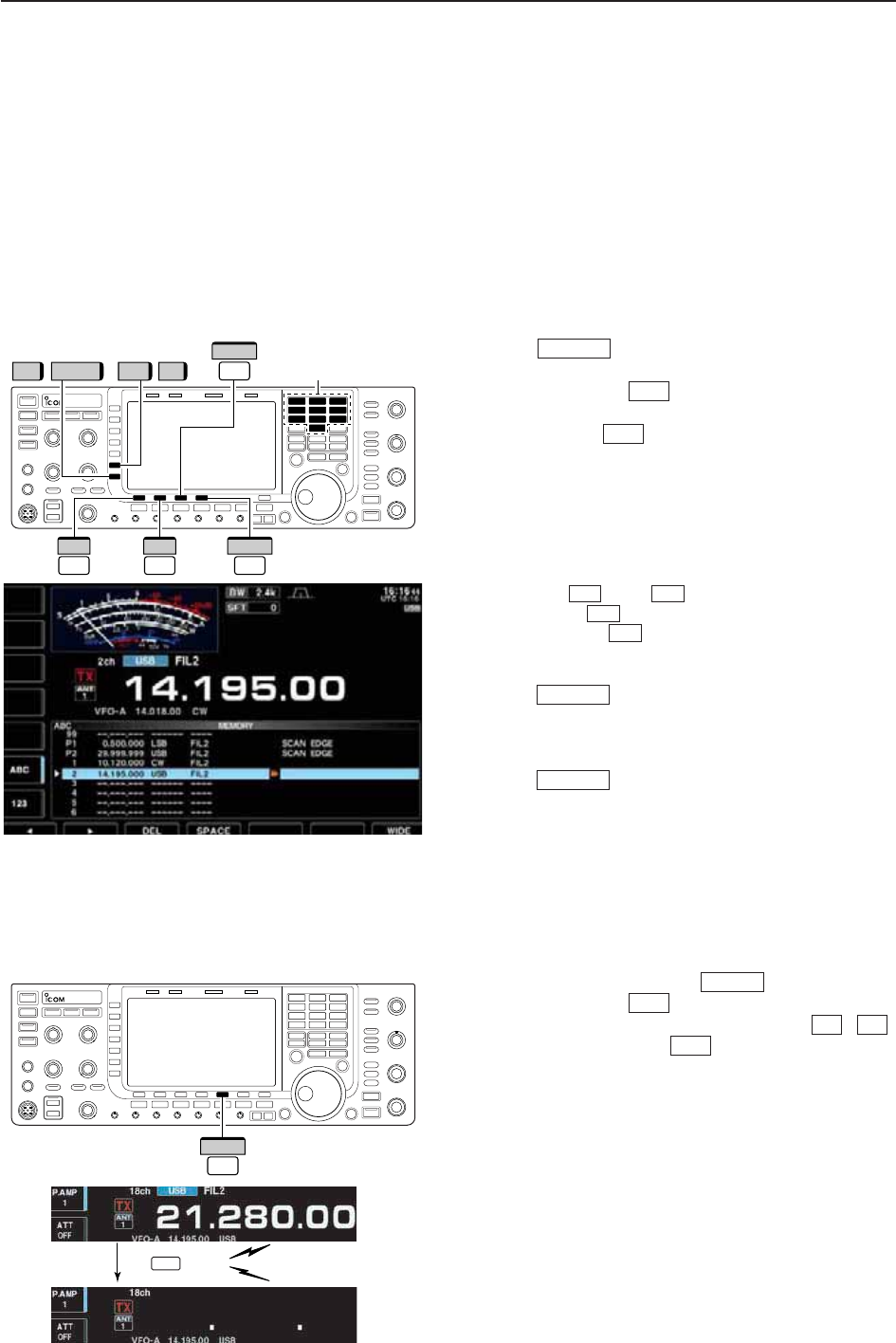
■Memory names
All memory channels (including scan edges) can be
tagged with alphanumeric names of up to 10 charac-
ters each.
Capital letters, small letters, numerals, some symbols
(! # $ % & ¥ ? " ’ ` ^ + – ✱/ . , : ; = < > ( ) [ ] { } | _ ~@)
and spaces can be used.
D
Editing (programming) memory names
qPush several times to close a multi-func-
tion screen, if necessary.
wPush [MEMORY] to select memory list screen.
eSelect the desired memory channel.
rPush [NAME] to edit memory channel name.
• A cursor appears and blinks.
• Memory channel names of blank channels cannot be
edited.
tInput the desired character by rotating the main dial
or by pushing the keypad for number input.
• Push [ABC] or [abc] to toggle capital and small letters.
• Push [123] or [Symbol] to toggle numerals and symbols.
• Push [Ω] or [≈] for cursor movement.
• Push [DEL] to delete the selected character.
• Push [SPACE] to input a space.
• Pushing the transceiver’s keypad, [0]–[9], can also enter
numerals.
yPush to input and set the name.
• The cursor disappears.
uRepeat steps eto yto program another memory
channel’s name, if desired.
iPush to exit memory list screen.
■Memory clearing
Any unused memory channels can be cleared. The
cleared memory channels become blank channels.
qSelect memory mode with .
wPush [MEMORY] to select memory list screen.
eSelect the desired memory channel with / .
rPush and hold [CLR] for 1 sec. to clear the
contents.
• The programmed frequency and operating mode disap-
pear.
tTo clear other memory channels, repeat steps e
and r.
F-5
√
∫
F-4
V/M
EXIT/SET
EXIT/SET
F-4
F-3
F-2F-1
F-4
F-4
EXIT/SET
Push for 1 sec.
Beep
Beep
Beep
(CLR)
F-5
F-5
CLR
Keypad
//
F-3
DEL
123 Symbol ABC abc
F-1
Ω
F-2
≈
F-4
SPACE
8-7
8
MEMORY OPERATION
■Memo pads
The transceiver has a memo pad function to store fre-
quency and operating mode for easy write and recall.
The memo pads are separate from memory channels.
The default number of memo pads is 5, however, this
can be increased to 10 in set mode if desired.
(p. 12-15)
Memo pads are convenient when you want to memo-
rize a frequency and operating mode temporarily, such
as when you find a DX station in a pile-up, or when a
desired station is busy for a long time and you want to
temporarily search for other stations.
Use the transceiver’s memo pads instead of relying on
hastily scribbled notes that are easily misplaced.
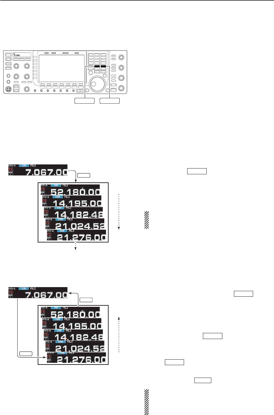
D
Writing frequencies and operating modes into memo pads
You can store the readout frequency and operating
mode by pushing .
When you store a 6th frequency and operating mode,
the oldest stored frequency and operating mode are
automatically erased to make room for the new set-
tings.
Each memo pad must have its own unique combi-
nation of frequency and operating mode; memo
pads having identical settings cannot be written.
D
Calling up a frequency from a memo pad
You can call up the desired frequency and operating
mode of a memo pad by pushing several
times.
• Both VFO and memory modes can be used.
• The frequency and operating mode are called up, starting
from the most recently written.
When you call up a frequency and an operating mode
from memo pads with , the previously dis-
played frequency and operating mode are automati-
cally stored in a temporary pad. The frequency and op-
erating mode in the temporary pad can be recalled by
pushing several times.
• You may think there are 6 memo pads because 6 different
frequencies (5 are in memo pads and 1 is in the temporary
pad) are called up by .
If you change the frequency or operating mode
called up from a memo pad with the main dial, etc.,
the frequency and operating mode in the temporary
pad are erased.
MP-R
MP-R
MP-R
MP-R
MP-W
MEMO PADS
MP-R
MP-R
Newest
Oldest
Newest
Erased
Oldest
In this example, 21.276 MHz (USB) will be
erased when 7.067 MHz (LSB) is written.
MP-W
MP-RMP-W

9-1
SCANS Section 9
■Scan types ……………………………………………………………… 9-2
■Preparation ……………………………………………………………… 9-2
■Voice squelch control function ………………………………………… 9-3
■Scan set mode ………………………………………………………… 9-3
■Programmed scan operation ………………………………………… 9-4
■∂F scan operation ……………………………………………………… 9-4
■Fine programmed scan/Fine ∂F scan ……………………………… 9-5
■Memory scan operation ………………………………………………… 9-6
■Select memory scan operation ……………………………………… 9-6
■Setting select memory channels ……………………………………… 9-7
DSetting in scan screen ……………………………………………… 9-7
DSetting in memory list screen ……………………………………… 9-7
DErasing the select scan setting …………………………………… 9-7
■Tone scan ……………………………………………………………… 9-8
9-2
■Scan types
• The scan function can be used on the main read-
out only.
• You can operate a scan while operating on a fre-
quency using the split functions.
PROGRAMMED SCAN
Repeatedly scans between two scan edge frequencies
(scan edge memory channels P1 and P2).
This scan operates in VFO mode.
SELECT MEMORY SCAN
Repeatedly scans all or one of 3 select memory channels.
∂F SCAN
Repeatedly scans within ∂F span area.
This scan operates in memory mode.This scan operates in memory mode.
This scan operates in both VFO and memory modes.
Scan
Scan edge
P1 or P2
Scan edge
P2 or P1
Jump
MEMORY SCAN
Repeatedly scans all programmed memory channels.
Mch 1
★
1
Mch 5
★
1
Mch 2
★
2
Mch 3
★
1Mch 4
Mch 6
★
3
Mch 7
★
1
Mch 99
★
1
Mch 1
★
1
Mch 5
★
1
Mch 2
★
2
Mch 3
★
1Mch 4
Mch 6
★
3
Mch 7
★
1
Mch 99
★
1
Blank channel Blank channel
ScanScan
–∂F frequency +∂F frequency
Start frequency
Jump
*“
★
1,” “
★
2” and “
★
3” show that the channel
is specified as the select memory.
*“
★
1,” “
★
2” and “
★
3” show that the channel
is specified as the select memory.
9SCANS
■Preparation
• Channels
For programmed scan:
Program scan edge frequencies into scan edge mem-
ory channels P1 and P2.
For
∂
F scan:
Set the ∂F span (∂F scan range) in the scan screen.
For memory scan:
Program 2 or more memory channels except scan
edge memory channels.
For select memory scan:
Designate 2 or more memory channels as select mem-
ory channels. To designate the channel as a select
memory channel, choose a memory channel, then
push [SELECT] in the scan screen (memory
mode) or in the memory list screen.
• Scan resume ON/OFF
You can select the scan to resume or cancel when de-
tecting a signal in set mode. Scan resume ON/OFF
must be set before operating a scan. See p. 9-3 for
ON/OFF setting and scan resume condition details.
• Scan speed
Scan speed can be selected from 2 levels, high or low,
in scan set mode. See p. 9-3 for details.
• Squelch condition
F-3
SQUELCH
CLOSED
SQUELCH
OPEN
Scan stops when detecting a signal.
If you set scan resume ON in set mode, the
scan pauses for 10 sec. when detecting a
signal, then resumes. When a signal disap-
pears while scan is paused, scan resumes
2 sec. later.
The scan continues
until it is stopped
manually, and does
not pause even if it
detects signals.
Scan pauses on
each channel when
the scan resume is
ON; not applicable
when OFF.
SCAN PROGRAMMED
STARTS SCAN MEMORY SCAN
WITH
9-3
■Voice squelch control function
This function is useful when you don’t want unmodu-
lated signals pausing or cancelling a scan. When the
voice squelch control function is activated, the trans-
ceiver checks received signals for voice components.
If a received signal includes voice components, and
the tone of the voice components changes within
1 sec., scan pauses (or stops). If the received signal
includes no voice components or the tone of the voice
components does not change within 1 sec., scan re-
sumes.
➥While a phone mode (SSB, AM or FM) is selected,
push [VSC] (MF7) to switch the VSC (Voice Squelch
Control) function ON and OFF.
• “VSC” appears when the function is activated.
• The VSC function activates for any scan.
• The VSC function resumes the scan on unmodu-
lated signals, regardless of whether the scan re-
sume condition is set to ON or OFF.
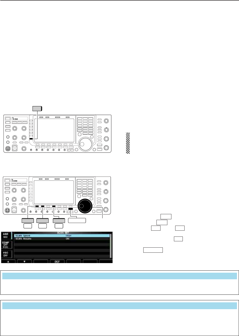
■Scan set mode
When the squelch is open, scan continues until it is
stopped manually— it does not pause on detected sig-
nals. When squelch is closed, scan stops when de-
tecting a signal, then resumes according to the scan
resume condition. Scan speed and the scan resume
condition can be set using the scan set mode.
qPush [SCAN] to select scan screen.
wPush [SET] to select scan set mode.
ePush [Y] or [Z] to select the desired item.
rRotate the main dial to select the desired condition.
• Push and hold [DEF] for 1 sec. to select the default
setting.
tPush to return to scan menu.
EXIT/SET
F-4
F-2F-1
F-7
F-5
Main dial
F-4
DEF
F-1
∫
F-2
√EXIT/SET
VSC
9
SCANS
Select the desired scan speed from high and low. • HIGH : scan is faster
• LOW : scan is slower
Scan Speed
HIGH
Set the scan resume function ON and OFF. • ON : When detecting a signal, scan pauses for
10 sec., then resumes. When a signal disap-
pears, scan resumes 2 sec. later.
• OFF : When detecting a signal, cancels scanning.
Scan Resume
ON
9-4
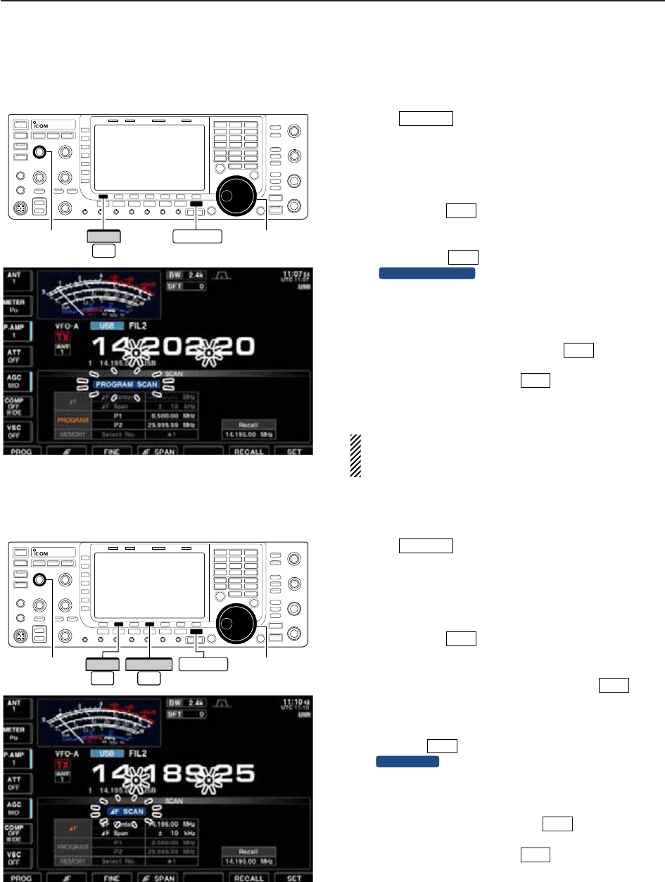
■Programmed scan operation
qPush several times to close a multi-func-
tion screen, if necessary.
wSelect VFO mode.
eSelect the desired operating mode.
• The operating mode can also be changed while scan-
ning.
rPush [SCAN] to select the scan screen.
tSet [SQL] open or closed.
• See page 9-2 for squelch condition.
yPush [PROG] to start the programmed scan.
• “ ” and decimal points blink while
scanning.
uWhen the scan detects a signal, scan stops, pauses
or ignores it depending on the resume setting and
the squelch condition.
iTo cancel the scan, push [PROG] .
• Rotating the main dial also cancels the scan.
oPush and hold [RECALL] for 1 sec. to recall
the frequency that is set before starting the scan, if
desired.
If the same frequencies are programmed into the
scan edge memory channel P1 and P2, pro-
grammed scan will not start.
■
∂
F scan operation
qPush several times to close a multi-func-
tion screen, if necessary.
wSelect VFO mode or a memory channel.
eSelect the desired operating mode.
• The operating mode can also be changed while scan-
ning.
rPush [SCAN] to select the scan screen.
tSet the main band’s [SQL] open or closed.
• See page 9-2 for squelch condition.
ySet the ∂F span by pushing [∂F SPAN] .
• ±5 kHz, ±10 kHz, ±20 kHz, ±50 kHz, ±100 kHz,
±500 kHz and ±1000 kHz are selectable.
uSet center frequency of the ∂F span.
iPush [∂F] to start the ∂F scan.
• “ ” and decimal points blink while scanning.
oWhen the scan detects a signal, the scan stops,
pauses or ignores it depending on the resume set-
ting and the squelch condition.
!0 To cancel the scan, push [∂F] .
• Rotating the main dial also cancels the scan.
!1 Push and hold [RECALL] for 1 sec. to recall
the frequency that was set before starting the scan.
F-6
F-2
:F SCAN
F-2
F-4
F-5
EXIT/SET
F-6
F-1
PROGRAM SCAN
F-1
F-5
EXIT/SET
[SQL] Main dial
EXIT/SET
F-1
PROG
[SQL] Main dial
F-2
∂F
F-4
∂F SCAN EXIT/SET
9SCANS
9-5
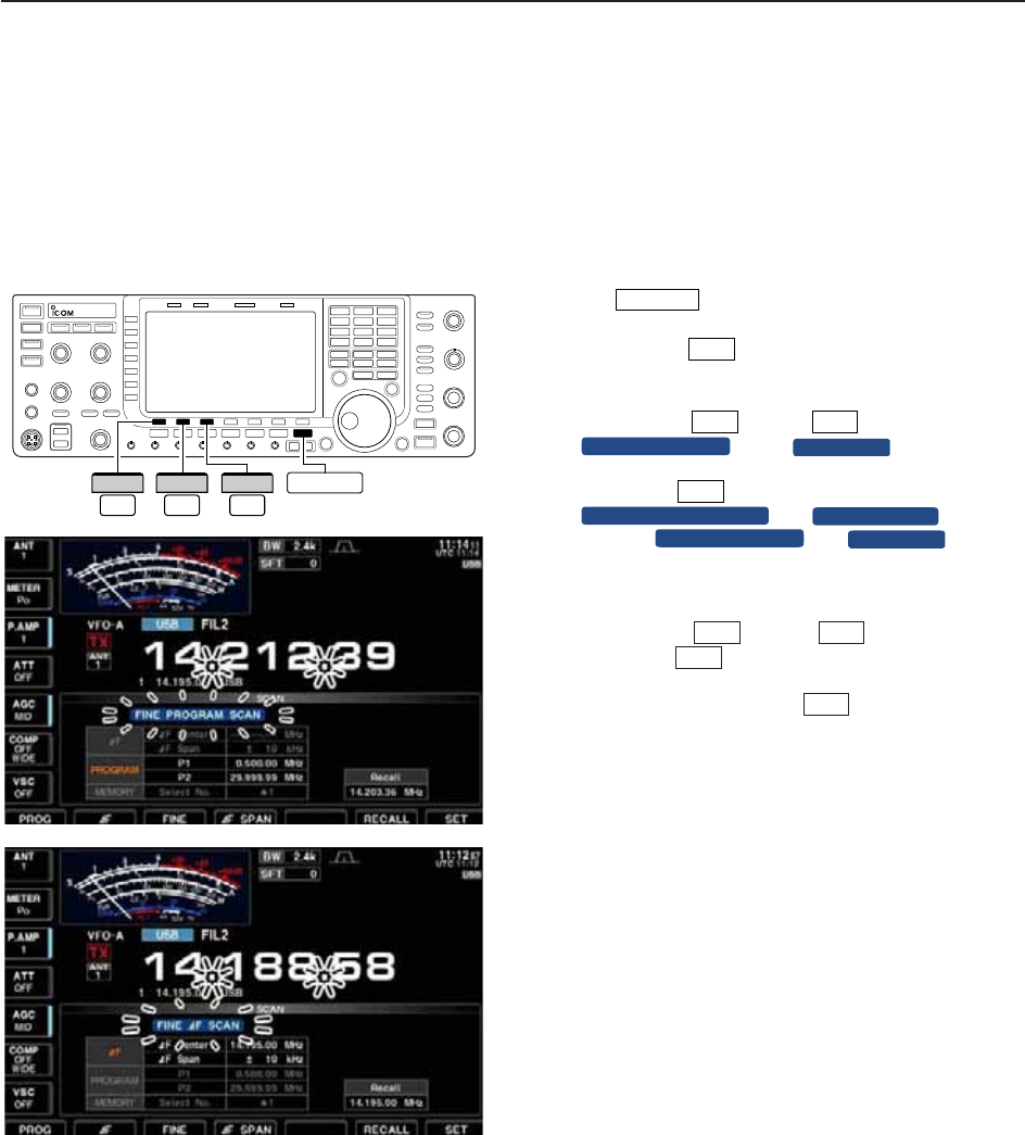
■Fine programmed scan/Fine ∂F scan
In fine scan (programmed or ∂F), the scan speed de-
creases when the squelch opens, but the transceiver
keeps scanning. The scanning tuning step shifts from
50 Hz to 10 Hz when the squelch opens.
qPush several times to close a multi-func-
tion screen, if necessary.
wPush [SCAN] to select the scan screen.
eSet for programmed scan or ∂F scan as described
on previous page.
rPush [PROG] or [∂F] to start a scan.
• “ ” or “ ” and decimal
points blink while scanning.
tPush [FINE] to start a fine scan.
• “ ” or “ ” blinks in-
stead of “ ” or “ ,” respec-
tively.
yWhen the scan detects a signal, the scan speed de-
creases but scan does not stop.
uPush [PROG] or [∂F] to stop the scan;
push [FINE] to cancel the fine scan.
• Rotating the main dial also cancels the scan.
iPush and hold [RECALL] for 1 sec. to recall
the frequency that is set before starting the scan, if
desired.
F-6
F-3
F-2F-1
:F SCAN
PROGRAM SCAN
FINE :F SCAN
FINE PROGRAM SCAN
F-3
:F SCAN
PROGRAM SCAN
F-2F-1
F-5
EXIT/SET
F-2
∂F
F-3
FINE
F-1
PROG EXIT/SET
9
SCANS
9-6
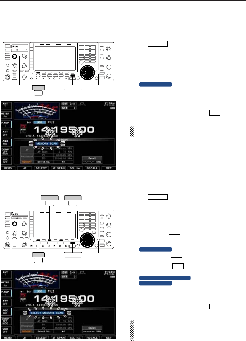
■Memory scan operation
qPush several times to close a multi-func-
tion screen, if necessary.
wSelect memory mode.
ePush [SCAN] to select the scan screen.
rSet [SQL] open or closed.
• See page 9-2 for squelch condition.
tPush [MEMO] to start the memory scan.
• “ ” and decimal points blink while scan-
ning.
yWhen the scan detects a signal, the scan stops,
pauses or ignores it depending on the resume set-
ting and the squelch condition.
uTo cancel the scan, push [MEMO] .
• Rotating the main dial also cancels the scan.
2 or more memory channels must be programmed
for memory scan to start.
■Select memory scan operation
qPush several times to close a multi-func-
tion screen, if necessary.
wSelect memory mode.
ePush [SCAN] to select the scan screen.
rSet [SQL] open or closed.
• See page 9-2 for squelch condition.
tPush [SEL No.] several times to select the se-
lect scan number from ★1, ★2, ★3 and ★1/★2/★3.
yPush [MEMO] to start the memory scan.
• “ ” and decimal points blink while scan-
ning.
uPush [SELECT] to start select memory scan;
push [SELECT] again to return to memory
scan, if desired.
• “ ” blinks instead of
“ ” during select memory scan.
iWhen the scan detects a signal, the scan stops,
pauses or ignores it depending on the resume set-
ting and the squelch condition.
oTo cancel the scan, push [MEMO] .
• Rotating the main dial also cancels the scan.
2 or more memory channels must be designated as
select memory channels, as well as the same select
scan channel number, for select memory scan to
start.
F-1
MEMORY SCAN
SELECT MEMORY SCAN
F-3
F-3
MEMORY SCAN
F-1
F-5
F-5
EXIT/SET
F-1
MEMORY SCAN
F-1
F-5
EXIT/SET
[SQL] Main dial
EXIT/SET
F-1
MEMO
F-3
SELECT
F-5
SEL No.
[SQL] Main dial
EXIT/SET
F-1
MEMO
9SCANS
9-7
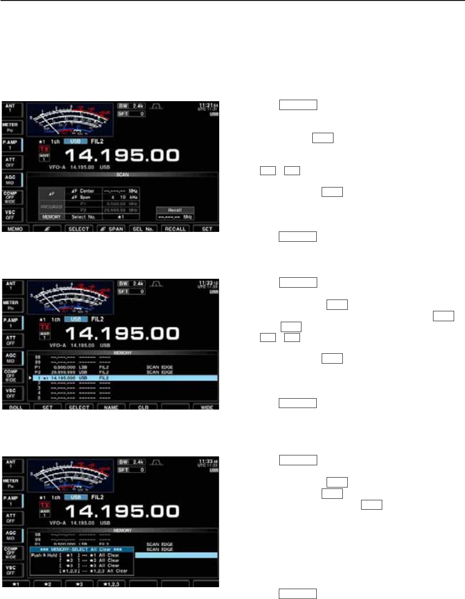
■Setting select memory channels
D
Setting in scan screen
qPush several times to close a multi-func-
tion screen, if necessary.
wSelect memory mode.
ePush [SCAN] to select the scan screen.
rSelect the desired memory channel to set as a se-
lect memory channel.
• / keys and direct keypad selections can be
used.
tPush [SELECT] several times to set the mem-
ory channel as a select memory ★1, ★2, ★3 or not.
yRepeat steps rto tto program another memory
channel as a select memory channel.
uPush to exit the scan screen.
D
Setting in memory list screen
qPush several times to close a multi-func-
tion screen, if necessary.
wPush [MEMORY] to select memory list screen.
eRotate the main dial while pushing [ROLL] or
[SET] to select the desired memory channel.
• / keys and direct keypad selections can be
used.
rPush [SELECT] several times to set the mem-
ory channel as a select memory ★1, ★2, ★3 or not.
tRepeat steps eto rto program another memory
channel as a select memory channel.
yPush to exit the memory list screen.
D
Erasing the select scan setting
qPush several times to close a multi-func-
tion screen, if necessary.
wPush [MEMORY] to select memory list screen,
or push [SCAN] to select scan screen.
ePush and hold [SELECT] for 1 sec. to display
memory select all clear window.
rPush one of the following keys to clear all select
scan setting.
[F-1•★1] : Clears all ★1 setting.
[F-2•★2] : Clears all ★2 setting.
[F-3•★3] : Clears all ★3 setting.
[F-4•★1,2,3] : Clears all select setting.
tPush to exit the memory list screen.
EXIT/SET
F-3
F-5
F-4
EXIT/SET
EXIT/SET
F-3
√
∫
F-2
F-1
F-4
EXIT/SET
EXIT/SET
F-3
√
∫
F-5
EXIT/SET
9
SCANS
9-8
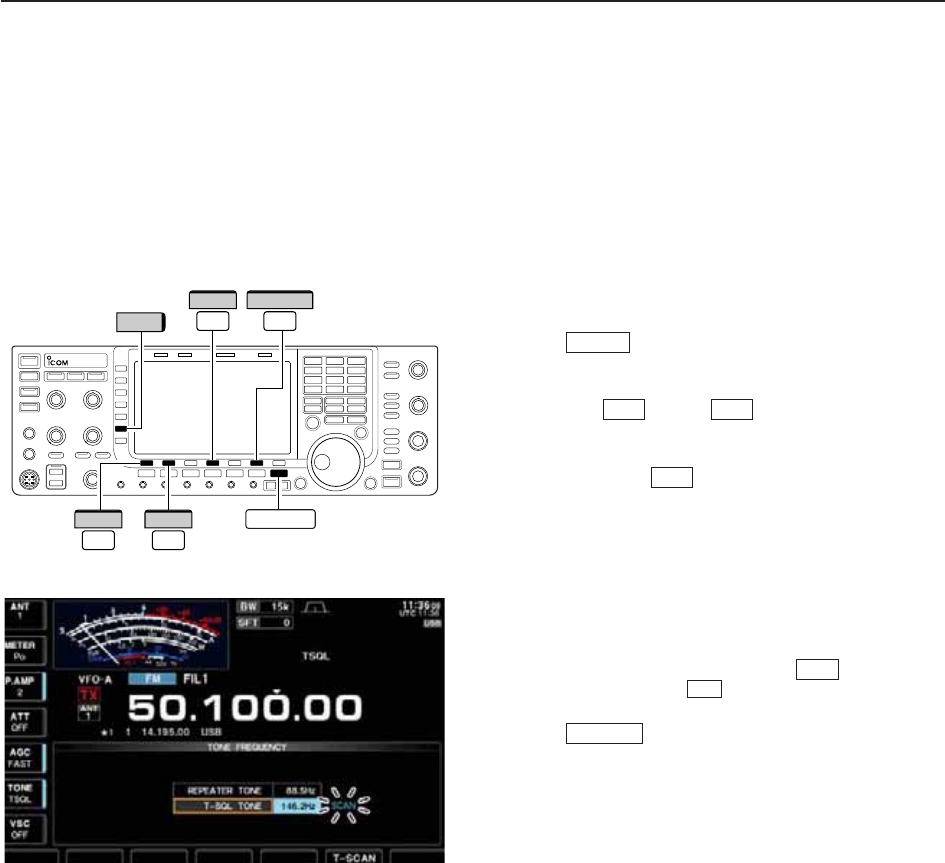
■Tone scan
The transceiver can detect subaudible tones in a re-
ceived signal. By monitoring a signal that is being
transmitted on a repeater input frequency, you can de-
termine the tone frequency required to access the re-
peater.
qSet the desired frequency or memory channel to be
checked for a tone frequency.
wPush several times to select FM mode.
ePush and hold [TONE] (MF6) for 1 sec. to enter tone
frequency screen.
rPush [Y] or [Z] to check the repeater
tone frequency or tone squelch frequency, respec-
tively.
tPush [T-SCAN] to start the tone scan.
• “SCAN” blinks while scanning.
yWhen the tone frequency is detected, the tone scan
pauses.
• The tone frequency is set temporarily on a memory
channel. Program the memory channel to store the tone
frequency permanently.
• The decoded tone frequency is used for the repeater
tone frequency or tone squelch frequency.
uTo stop the scan, push [T-SCAN] .
• Push and hold [DEF] for 1 sec. to select the default
frequency.
iPush to exit tone frequency screen.
EXIT/SET
F-4
F-6
F-6
F-2F-1
AM/FM
EXIT/SET
F-1
∫
F-2
√
F-4 F-6
T-SCANDEF
TONE
9SCANS

10-1
ANTENNA TUNER OPERATION Section 10
■Antenna connection and selection ………………………………… 10-2
■Antenna memory settings …………………………………………… 10-3
DAntenna type selection …………………………………………… 10-3
DTemporary memory ………………………………………………… 10-4
DAntenna selection mode …………………………………………… 10-4
DReceive antenna I/O setting ……………………………………… 10-5
■Antenna tuner operation ……………………………………………… 10-6
DTuner operation …………………………………………………… 10-6
DIf the tuner cannot tune the antenna …………………………… 10-7
10-2
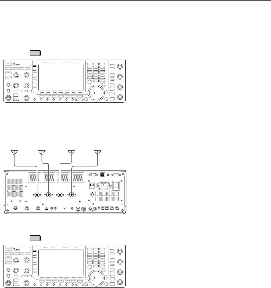
■Antenna connection and selection
The IC-7700 has 4 antenna connectors for the
HF/50 MHz bands, [ANT1], [ANT2], [ANT3], and
[ANT4].
For each operating band the IC-7700 covers, there is a
band memory which can memorize the selected an-
tenna. When you change the operating frequency out-
side of a band, the previously used antenna is auto-
matically selected (see below) for the new band. This
function allows automatic switching of 4 separate an-
tennas for HF and 50 MHz bands operation.
• Antenna selection mode: “Auto”
After an antenna has been selected for use (by push-
ing [ANT] (MF1)), the antenna is automatically selected
whenever that band is used.
[EXAMPLE]: a 3.5/7 MHz antenna is connected to
[ANT1], a 21/28 MHz antenna is connected to [ANT2],
a 50 MHz antenna is connected to [ANT3]. When the
antenna selector function is set to “Auto,” an antenna
is automatically selected when changing bands.
A receive-only antenna can be specified for [ANT4].
• Antenna selection mode: “Manual”
When “Manual” is selected, you can use the all an-
tenna connectors, [ANT1] [ANT2], [ANT3] and [ANT4],
however, band memory does not function. In this case
you must select an antenna manually.
• Antenna selection mode: “OFF”
In this case, only [ANT1] antenna connector can be
used. [ANT] (MF1) switch does not function.
ANT
ANT 1
ANT 2 ANT 3
ANT 4
3.5/7 MHz
bands
21/28 MHz
bands
50 MHz
bands
RX
only
ANT
10 ANTENNA TUNER OPERATION
10-3
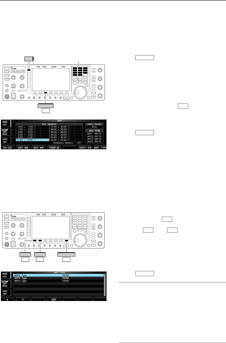
■Antenna memory settings
This function stores the antenna connector number for
each frequency band.
qPush several times to close multi-function
screen, if necessary.
wPush and hold [ANT] (MF1) for 1 sec. to select an-
tenna set screen.
eSelect the desired frequency band with a band key.
rPush [ANT] (MF1) several times to select the desired
antenna number that you want to set for the se-
lected frequency band.
•“★” appears.
tPush and hold [ANT MW] for 1 sec. to store
the antenna selection into the antenna memory.
•“★” disappears.
yRepeat the steps eto tto store the antenna se-
lection for another frequency bands, if desired.
uPush to exit antenna set screen.
D
Antenna type selection
When no antenna is connected to [ANT2], [ANT3],
and/or [ANT4], these antenna connectors can be de-
activated — deleting the antenna number from the
available selections. This prevents the transceiver from
accidentally transmitting into an unused antenna con-
nector. In addition, a receive-only antenna can be
specified for [ANT4].
qSelect the antenna set screen as described above.
wPush [ANT TYPE] to select antenna type set
screen.
ePush [Y] or [Z] to select the desired an-
tenna.
rRotate the main dial to select the desired antenna
condition from TX/RX, RX (ANT4 only) and OFF.
• TX/RX : Select when an antenna is connected.
• OFF : Select when no antenna is connected.
• RX : Select when a receive only antenna is
connected. (available for the [ANT4] only)
tPush to exit antenna type set screen.
✔
For your information
The “OFF” antennas cannot be selected with [ANT]
(MF1) switch operation, or with the antenna memory
setting.
When “RX” is selected for [ANT4], “1/R,” “2/R” and
“3/R” selections will be added for the selection for both
[ANT] (MF1) switch operation and the antenna memory
setting. In these selections, the antenna connected to
[ANT1], [ANT2] and/or [ANT3] will be used for trans-
mission and the antenna connected to [ANT4] will be
used for reception.
EXIT/SET
F-2F-1
F-7
EXIT/SET
F-3
EXIT/SET
Band keys
ANT
F-3
ANT MW
F-1
∫
F-2
√
F-7
ANT TYPE
10
ANTENNA TUNER OPERATION
10-4
■Antenna memory settings (continued)
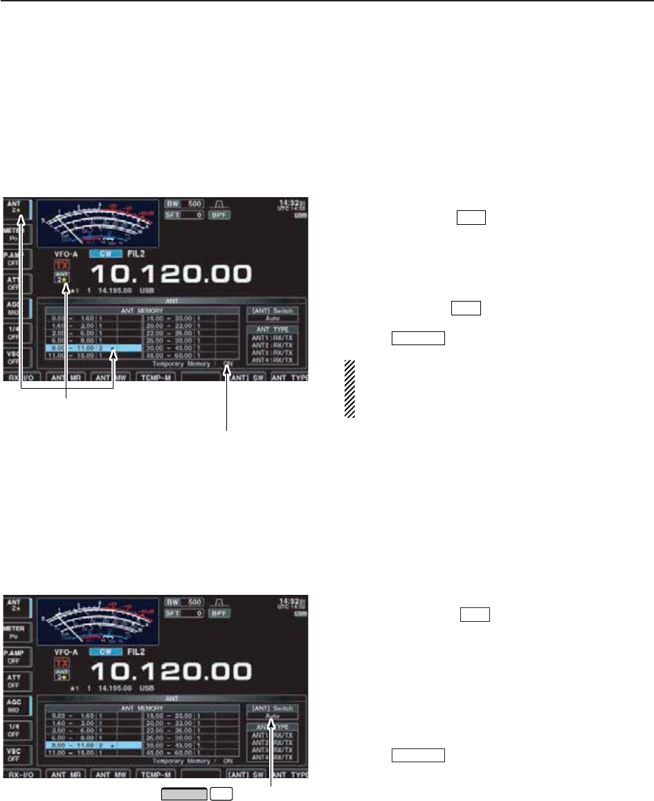
D
Temporary memory
The antenna temporary memory memorizes the man-
ually selected antenna. The selected antenna will be
re-called even if frequency band has been changed.
qSelect the antenna set screen.
wPush [TEMP-M] to turn the temporary mem-
ory ON and OFF.
eSelect the desired frequency band with a band key.
rPush [ANT] (MF1) to select the desired antenna.
•“★” appears when a different antenna from the original is
selected.
tPush [ANT MR] to re-call the original antenna.
•“★” disappears.
yPush to exit antenna set screen.
CAUTION!: Before transmitting with the manually
selected antenna, make sure the selected antenna
suits the operating frequency. Otherwise the trans-
ceiver may be damaged.
D
Antenna selection mode
The automatic antenna selection (antenna memory)
and the [ANT] (MF1) switch function can be deactivated
if desired.
qSelect the antenna set screen.
wPush [[ANT]SW] to select the antenna selec-
tion from Auto, OFF and Manual.
• Auto : Use the antenna memory. Antenna selec-
tion with [ANT] switch is also available.
• OFF : Only the antenna connected to [ANT1]
can be used. [ANT] switch is deactivated.
• Manual: Deactivate the antenna memory function.
Antenna can be selected with [ANT]
switch operation only.
ePush to exit antenna set screen.
EXIT/SET
F-6
EXIT/SET
F-2
F-4
Push to select the
antenna selection mode.
F-6
[ANT] SW
“★” indicators appear when a different
antenna from the original is selected.
Push [F-4•TEMP-M] to turn the
temporary memory ON and OFF.
10 ANTENNA TUNER OPERATION
10-5
10
ANTENNA TUNER OPERATION
D
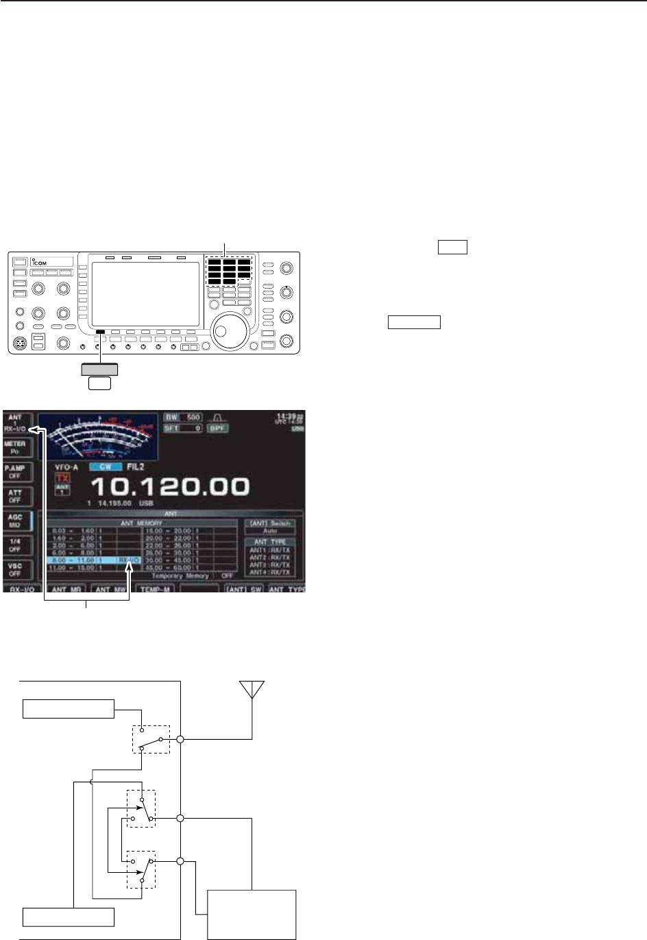
Receive antenna I/O setting
In default setting, receive antenna connectors, [RX
ANT-IN] and [RX ANT-OUT], on the rear panel are de-
activated and are connected internally by the switch-
ing relay. If you want to connect an external preamp or
low-pass filter between the [RX ANT-IN] and [RX ANT-
OUT], you must activate them as described below.
qSelect the antenna set screen.
wSelect the desired frequency band with a band key.
ePush [RX-I/O] to activate the receive antenna
connectors ([RX ANT-IN] and [RX ANT-OUT]).
• “RX-I/O” indicators appear when [RX ANT-IN] and [RX-
ANT-OUT] are active.
rRepeat steps wand e, if desired.
tPush to exit antenna set screen.
EXIT/SET
F-1
“RX-I/O” indicators appear when [RX ANT-IN]
and [RX ANT-OUT] are active.
Band keys
F-1
RX-I/O
Receiver
Preamp or
Low-pass filter,
etc.
Transmitter
Transceiver
IN
[RX ANT]
OUT
Transmit/Receive
switching circuit
ANT
RX
only
10-6
10 ANTENNA TUNER OPERATION
■Antenna tuner operation
The internal automatic antenna tuner matches the
transceiver to the connected antenna automatically.
After the tuner matches an antenna, the variable ca-
pacitor settings are memorized as a preset point for
each frequency range (100 kHz steps). Therefore,
when you change the frequency range, the variable ca-
pacitors are automatically preset to the memorized set-
ting.
CAUTION: NEVER transmit with the tuner ON when
no antenna is connected. This will damage the
transceiver. Be careful of the antenna selection.
D
Tuner operation
➥Push to turn the internal antenna tuner ON.
The antenna is tuned automatically when the an-
tenna SWR is higher than 1.5:1.
• When the tuner is ON, [TUNER] switch indicator lights
green.
• While tuning, [TUNER] switch indicator blinks green.
• MANUAL TUNING
During SSB operation at low voice levels, the internal
tuner may not be tuned correctly. In such cases, man-
ual tuning is helpful.
➥Push and hold for 1 sec., to start manual
tuning.
• A side tone is emitted and [TUNER] switch indicator
blinks red while tuning.
• If the tuner cannot reduce the SWR to less than 1.5:1
after 20 sec. of tuning, the [TUNER] switch indicator
goes out.
• AUTOMATIC TUNER START (HF bands only)
If you want to deactivate the tuner under conditions of
VSWR 1.5:1 or less, use the auto tuner start function
and turn the tuner OFF. This function activates the
tuner automatically when the SWR exceeds 1.5:1.
This function is turned ON in set mode. (p. 12-13).
TUNER
TUNER
TUNER
NOTES:
•NEVER transmit without an antenna properly con-
nected to antenna port in use.
• When 2 or more antennas are connected, select
the antenna to be used with [ANT].
• If the SWR is higher than about 1.5:1 when tuning
above 100 kHz on an antenna’s preset point, push
and hold for 1 sec. to start manual tuning.
• The internal tuner may not be able to tune in AM
mode. In such cases, push and hold for
1 sec. to manually tune.
TUNER
TUNER

10-7
10
ANTENNA TUNER OPERATION
■Antenna tuner operation (continued)
• PTT TUNER START
The tuner is always tuned when the PTT is pushed
after the frequency is changed (more than 1% from
last-tuned frequency). This function removes the “push
and hold ” operation and activates for the first
transmission on a new frequency.
This function is turned ON in set mode. (p. 12-13).
• Antenna tuner of the IC-PW1
When using an external antenna tuner such as the IC-
PW1’s tuner, tune with the external antenna tuner, and
turn OFF the IC-7700’s tuner. After tuning is com-
pleted, turn the internal tuner ON. Otherwise, both
tuners tune simultaneously and correct tuning may not
be obtained.
See the instruction manual included with each antenna
tuner for their respective operations.
D
If the tuner cannot tune the antenna
Check the following and try again:
• the [ANT] connector selection.
• the antenna connection and feedline.
• the untuned antenna SWR. (Less than 3:1 for HF bands; Less
than 2.5:1 for 50 MHz band)
• the transmit power. (8 W for HF bands; 15 W for 50 MHz band)
• the power source voltage/capacity.
If the tuner cannot reduce the SWR to less than 1.5:1
after checking the above, perform the following:
• repeat manual tuning several times.
• tune with a 50 dummy load and re-tune the antenna.
• turn power OFF and ON.
• adjust the antenna feedline length.
(This is effective for higher frequencies in some cases.)
• Some antennas, especially for low bands, have a narrow
bandwidth. These antennas may not be tuned at the edge
of their bandwidth, therefore, tune such an antenna as fol-
lows:
[Example]: Suppose you have an antenna which has an
SWR of 1.5:1 at 3.55 MHz and an SWR of 3:1
at 3.8 MHz.
qPush to turn the antenna tuner ON.
wSelect CW mode.
eTurn OFF the break-in function. (p. 6-3)
rPush to set to the transmit condition.
tSet 3.55 MHz and key down.
ySet 3.80 MHz and key down.
uPush to return to the receive condition.
TRANSMIT
TRANSMIT
TUNER
TUNER

11-1
CLOCK AND TIMERS Section 11
■Time set mode ………………………………………………………… 11-2
■Daily timer setting ……………………………………………………… 11-3
■Setting sleep timer …………………………………………………… 11-4
■Timer operation ………………………………………………………… 11-4
11-2
■Time set mode
The IC-7700 has a built-in calendar and 24-hour clock
(accuracy ±75 sec. per month) with daily power
ON/OFF timer functions. Before operating these timer
functions, set the current date and time.
qPush to close multi-function screen, if
necessary.
wPush [SET] to select set mode menu screen.
ePush [TIME] to select time set mode.
rPush [Y] or [Z] to select the desired item.
tRotate the main dial to set or select the desired
value or condition.
yPush to exit time set mode.
EXIT/SET
F-2F-1
F-4
F-7
EXIT/SET
Main dial
EXIT/SET
//
/
F-3
Ω ≈
F-5
EDIT SET
123 Symbol ABC abc
F-1
Ω
F-2
≈
F-4
DEF
11 CLOCK AND TIMERS
Sets the date. zPush [Ω≈] to select between the year and the
month/day, then rotate the main dial to select them.
• The date setting and “DATE-set Push [SET]” indication
blink.
xPush [SET] to set the date.
F-5
F-3
Date
2000
–
1
–
1 ( Sat )
Sets the local time. zRotate the main dial to set the local time.
• The time setting and “TIME-set Push [SET]” indication
blink.
xPush [SET] to set the time.
F-5
Time (Now)
1:23
Turns the CLOCK2 indicator ON and OFF.
CLOCK2 is convenient to indicate UTC or other coun-
try’s local time, etc.
• ON : The CLOCK2 indicator is displayed below the
local time indication.
• OFF : The CLOCK2 indicator does not display.
CLOCK2 Function
ON
Sets the desired off-set time period for CLOCK2 dis-
play within –24:00 to +24:00 in 5 min. steps.
• Push and hold [DEF] for 1 sec. to select the default
value.
F-4
CLOCK2 Offset
0:00
Sets the desired 3-character name for CLOCK2.
Capital letters, small letters, numerals, some symbols
(! # $ % & ¥ ? " ’ ` ^ + – ✱/ . , : ; = < > ( ) [ ] { } | _ ~@)
and spaces can be used.
zPush [EDIT] to select the name edit condition.
• The cursor under the 1st character blinks.
xPush [ABC], [abc], [123] or [Symbol] to select the
character group, then rotate the main dial to select
the character.
• Push [ABC] or [abc] to toggle capital and small letters.
• Push [123] or [Symbol] to toggle numerals and sym-
bols.
• Push [Ω] or [≈] for cursor movement.
• Push [DEL] to delete the selected character.
• Push [SPACE] to input a space.
• Pushing the transceiver’s keypad, [0]–[9], can also
enter numerals.
cPush to set the name.
EXIT/SET
F-4
F-3
F-2F-1
F-5
CLOCK2 Name
UTC
11-3
■Daily timer setting
The transceiver turns power ON and/or OFF automat-
ically on the specified day and time, with the specified
frequency settings.
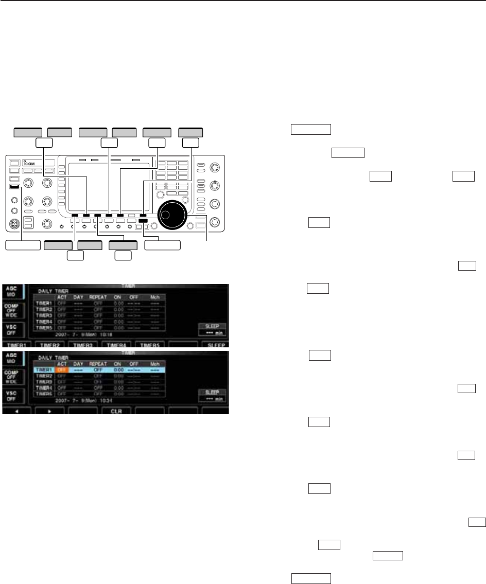
qPush several times to close multi-function
screen, if necessary.
wPush and hold for 1 sec. to select timer set
screen.
ePush one of [TIMER1] to [TIMER5] to
select the desired timer.
rRotate the main dial to select the timer action ON
and OFF.
tPush [≈] to select the “DAY” cell, then rotate
the main dial to select the desired day of the week.
• Select “– – –” not to specify the day of the week. The
timer will function every day in this case.
• Once a day of the week is selected, push [CLR] to
select “– – –.”
yPush [≈] to select the “REPEAT” cell, then ro-
tate the main dial to select the repeat function ON
and OFF.
• ON : The timer functions every selected day of the
week. (repeats)
• OFF : The timer does not repeat.
uPush [≈] to select the “ON” cell, then rotate
the main dial to set the desired transceiver power
ON time.
• When using power OFF timer only, push [CLR] to
select “– – –.” This setting cannot be set when the power
OFF timer is set to “– – –.”
iPush [≈] to select the “OFF” cell, then rotate
the main dial to set the desired transceiver power
OFF time.
• When using power ON timer only, push [CLR] to
select “– – –.” This setting cannot be set when the power
ON timer is set to “– – –.”
oPush [≈] to select the “Mch” cell, then rotate
the main dial to select the desired memory channel
number.
• If using the currently set VFO condition, push [CLR]
to select “– – –.”
!0 Push [SET] to set the timer.
• The timer indicator above switch lights green.
!1 Repeat steps eto !0 to set other timers, if desired.
!2 Push to exit timer set screen.
EXIT/SET
TIMER
F-7
F-4
F-2
F-4
F-2
F-4
F-2
F-2
F-4
F-2
F-5F-1
TIMER
EXIT/SET
Main dial
≈
F-2
TIMER2
F-3
TIMER3
TIMER4
EXIT/SET
//
Ω
F-1
TIMER1 /
F-4
TIMER5
F-5 F-7
SETCLR
TIMER
11
CLOCK AND TIMERS
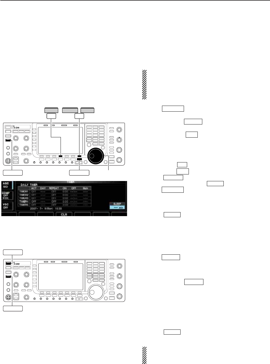
11-4
■Setting sleep timer
The sleep timer turns the transceiver power OFF au-
tomatically after passing the set period. The timer can
be set to 5–120 min. in 5 min. steps.
The sleep timer function counts the ‘minute’ units,
and does not count the ‘second’ units. For example,
when the sleep timer is started at 12:00 59, first one
minute past for just 1 sec. That is way it has a max.
59 sec. error. This is normal, not a malfunction.
qPush several times to close a multi-func-
tion screen, if necessary.
wPush and hold for 1 sec. to select timer set
screen.
ePush [SLEEP] to select the sleep timer set
condition.
• “– – –” blinks.
rSet the desired time period using the main dial.
• “TIMER–set Push [SET]” blinks.
• Push [CLR] to select “– – –” to cancel the setting.
tPush [SET] to set the time.
• Push to cancel the setting.
• The timer indicator above switch lights green.
yPush to exit timer set screen.
uThe transceiver emits 10 beeps and turns OFF after
the sleep timer period elapses.
• The timer indicator blinks while beeping.
• Push momentarily to cancel the sleep timer, if
desired.
■Timer operation
qPreset the daily timer as described previously.
wPush momentarily to turn the timer function
ON.
• The timer indicator above this switch lights green when
the timer function is ON.
ePush and hold for 1 sec. to turn the power
OFF.
• The timer indicator lights continuously.
rWhen the set time arrives, the power is automati-
cally turned ON.
tThe transceiver emits 10 beeps and turns OFF after
the power-off period elapses.
• The timer indicator blinks while beeping.
• Push momentarily to cancel the sleep timer, if
desired.
Timer action in the timer set screen must be se-
lected ON to enable timer operation, described in
page 11-3 steps r.
TIMER
POWER
TIMER
TIMER
EXIT/SET
TIMER
EXIT/SET
F-7
F-4
F-7
TIMER
EXIT/SET
Main dial
SLEEP
EXIT/SET
/
F-4 F-7
SETCLR
TIMER
POWER
TIMER
11 CLOCK AND TIMERS

12-1
SET MODE Section 12
■Set mode description ………………………………………………… 12-2
DSet mode operation ………………………………………………… 12-2
DScreen arrangement ……………………………………………… 12-3
■Level set mode ………………………………………………………… 12-4
■ACC set mode ………………………………………………………… 12-7
■Display set mode ……………………………………………………… 12-9
■Others set mode …………………………………………………… 12-12
■USB-Memory set menu …………………………………………… 12-19
DUSB-Memory set screen arrangement ………………………… 12-19
DSave option set mode …………………………………………… 12-20
DLoad option set mode …………………………………………… 12-21
■File saving …………………………………………………………… 12-22
■File loading …………………………………………………………… 12-23
■Changing a file name ……………………………………………… 12-24
■Deleting a file ………………………………………………………… 12-25
■Unmounting USB-Memory ………………………………………… 12-25
■Formatting the USB-Memory ……………………………………… 12-26
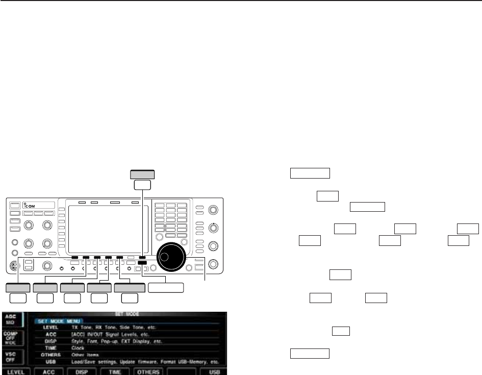
12-2
■Set mode description
Set mode is used for programming infrequently
changed values or conditions of functions. The IC-
7700 has a level set mode, display set mode, time set
mode, accessory set mode, Others set mode and
USB-Memory set menu.
D
Set mode operation
qPush several times to close a multi-func-
tion screen, if necessary.
wPush [SET] to select set mode menu screen.
• Pushing and holding for 1 sec. also selects set
mode menu screen.
ePush [LEVEL] , [ACC] , [DISP] ,
[TIME] , [OTHERS] or [USB] to
enter the desired set mode.
rFor level, accessory, display and Others set mode,
push [WIDE] to toggle wide and normal
screen.
tPush [Y] or [Z] to select the desired
item, then rotate the main dial to adjust/select the
desired value or condition.
• Pushing [Ω≈] operation may be necessary for
some items.
yPush twice to exit set mode.
EXIT/SET
F-3
F-2F-1
F-7
F-7F-5F-4
F-3F-2F-1
EXIT/SET
F-7
EXIT/SET
Main dial
F-1
LEVEL
F-2
ACC
F-5
OTHERS EXIT/SET
F-3
DISP
F-4
TIME
F-7
USB
12 SET MODE
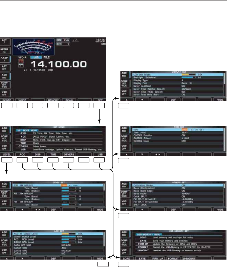
12-3
12
SET MODE
D
Screen arrangement
• Set mode menu screen (p. 12-2)
• Level set mode (p. 12-4)
• ACC set mode (p. 12-7)
• Time set mode (p. 11-2)
• Display set mode (p. 12-9)
• Others set mode (p. 12-12)
• USB-Memory set menu (p. 12-19)
F-1 F-2 F-3
F-3
F-4
F-5
F-7F-2
F-4 F-5 F-6 F-7
F-1 F-2 F-3 F-4 F-5 F-6 F-7
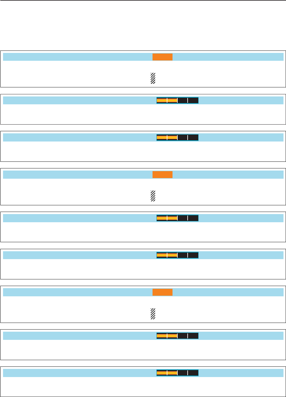
12-4
12 SET MODE
■Level set mode
Sets the bass level of the receive audio tone in SSB
mode from –5 to +5. (default: 0)
Tone (Bass)
0
Sets the treble level of the receive audio tone in SSB
mode from –5 to +5. (default: 0)
Tone (Treble)
0
Sets the bass level of the receive audio tone in AM
mode from –5 to +5. (default: 0)
Tone (Bass)
0
Sets the treble level of the receive audio tone in AM
mode from –5 to +5. (default: 0)
Tone (Treble)
0
Sets the bass level of the receive audio tone in FM
mode from –5 to +5. (default: 0)
Tone (Bass)
0
Sets the treble level of the receive audio tone in FM
mode from –5 to +5. (default: 0)
Tone (Treble)
0
Sets the low-pass filter (100 Hz to 2000 Hz) and high-
pass filter (500 Hz to 2400) of the receive audio in 100
Hz steps in SSB mode. (default: OFF)
NOTE: When this setting is active, below 2 items
will be reset to default value, ‘0.’
SSB RX HPF/LPF
– – – – – – –
Sets the low-pass filter (100 Hz to 2000 Hz) and high-
pass filter (500 Hz to 2400) of the receive audio in 100
Hz steps in AM mode. (default: OFF)
NOTE: When this setting is active, below 2 items
will be reset to default value, ‘0.’
AM RX HPF/LPF
– – – – – – –
Sets the low-pass filter (100 Hz to 2000 Hz) and high-
pass filter (500 Hz to 2400) of the receive audio in 100
Hz steps in FM mode. (default: OFF)
NOTE: When this setting is active, below 2 items
will be reset to default value, ‘0.’
FM RX HPF/LPF
– – – – – – –
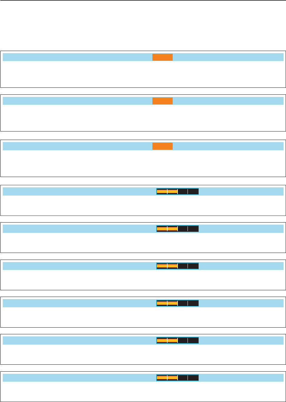
12-5
12
SET MODE
■Level set mode (continued)
Sets the bass level of the transmit audio tone in SSB
mode from –5 to +5. (default: 0)
SSB TX Tone (Bass)
0
Sets the treble level of the transmit audio tone in SSB
mode from –5 to +5. (default: 0)
Tone (Treble)
0
Sets the bass level of the transmit audio tone in AM
mode from –5 to +5. (default: 0)
AM TX Tone (Bass)
0
Sets the treble level of the transmit audio tone in AM
mode from –5 to +5. (default: 0)
Tone (Treble)
0
Sets the bass level of the transmit audio tone in FM
mode from –5 to +5. (default: 0)
FM TX Tone (Bass)
0
Sets the treble level of the transmit audio tone in FM
mode from –5 to +5. (default: 0)
Tone (Treble)
0
Sets the low-pass filter (100 Hz to 2000 Hz) and high-
pass filter (500 Hz to 2400) of the receive audio in 100
Hz steps in CW mode. (default: OFF)
CW RX HPF/LPF
– – – – – – –
Sets the low-pass filter (100 Hz to 2000 Hz) and high-
pass filter (500 Hz to 2400) of the receive audio in 100
Hz steps in RTTY mode. (default: OFF)
RTTY RX HPF/LPF
– – – – – – –
Sets the low-pass filter (100 Hz to 2000 Hz) and high-
pass filter (500 Hz to 2400) of the receive audio in 100
Hz steps in PSK mode. (default: OFF)
PSK RX HPF/LPF
– – – – – – –
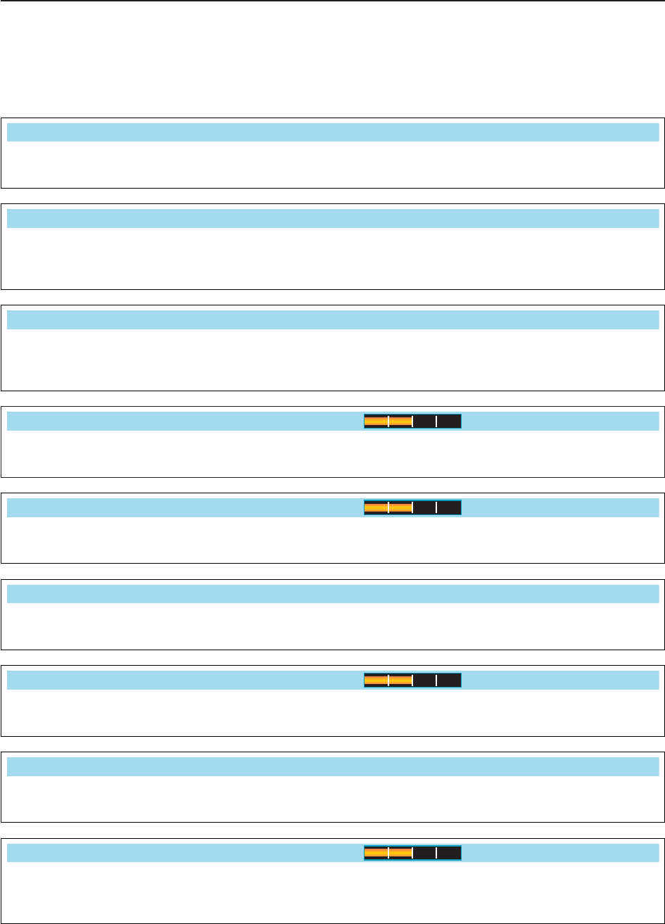
■Level set mode (continued)
12-6
12 SET MODE
Sets the voice synthesizer audio output level from 0 to
100% in 1% steps. (default: 50%)
Speech Level
50%
Sets the side tone output level from 0 to 100% in 1%
steps. (default: 50%)
Side Tone Level
50%
Turns the side tone output level limiting capability from
ON and OFF. (default: ON)
Side Tone Level Limit
ON
Sets the key-touch beep output level from 0 to 100%
in 1% steps. (default: 50%)
Beep Level
50%
Turns the key-touch beep output level limiting capa-
bility from ON and OFF. (default: ON)
Beep Level Limit
ON
Sets the ratio for audio output level from the head-
phone toward to the internal speaker within a range
of 0.60 to 1.40 in 0.01 steps. (default: 1.00)
Phones Level Ratio
1.00
Sets the transmission passband width to wide setting
by changing the lower and higher cut-off frequencies.
Lower freq. : 100 (default), 200, 300 and 500 Hz
Higher freq.: 2500, 2700, 2800 and 2900 Hz (default)
SSB TBW (WIDE)
100 – 2900
Sets the transmission passband width to middle set-
ting by changing the lower and higher cut-off frequen-
cies.
Lower freq. : 100, 200, 300 (default) and 500 Hz
Higher freq.: 2500, 2700 (default), 2800 and 2900 Hz
SSB TBW (MID)
300 – 2700
Sets the transmission passband width to narrow set-
ting by changing the lower and higher cut-off frequen-
cies.
Lower freq. : 100, 200, 300 and 500 Hz (default)
Higher freq.: 2500 (default), 2700, 2800 and 2900 Hz
SSB TBW (NAR)
500 – 2500
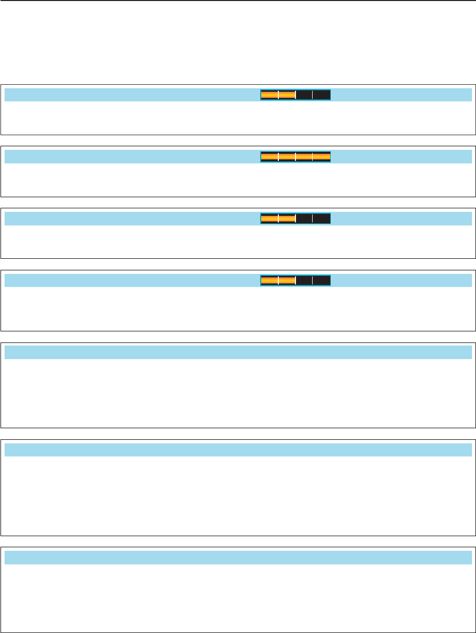
■ACC set mode
12-7
12
SET MODE
Sets the desired audio output level, output from
[ACC1], within 0 to 100% in 1% steps.
• Outputs approx. 200 mV at 50% (default) setting.
ACC AF Output Level
50%
Sets the desired output level of [S/P DIF], within 0 to
100% in 1% steps. (default: 100%)
S/PDIF Output Level
100%
Sets the desired audio input level for modulation from
[ACC1].
• Approx. 100 mV at 50% (default) setting.
ACC MOD Level
50%
Sets the desired input level for modulation from
[S/P DIF], within 0 to 100% in 1% steps.
(default: 50%)
S/PDIF MOD Level
50%
Selects the desired connector(s) for modulation input
when data mode is not in use.
• MIC : Use the signals from [MIC].
• ACC : Use the signals from [ACC1] (pin 4).
• MIC,ACC : Use the signals from [MIC] and [ACC1]
(pin 4). (default)
• S/P DIF : Use the signals from [S/P DIF].
DATA OFF MOD
MIC,ACC
Selects the desired connector(s) for modulation input
when data 1 mode (D1) is in use.
• MIC : Use the signals from [MIC].
• ACC : Use the signals from [ACC1] (pin 4).
(default)
• MIC,ACC : Use the signals from [MIC] and [ACC1]
(pin 4).
• S/P DIF : Use the signals from [S/P DIF].
DATA1 MOD
ACC
Selects the desired connector(s) for modulation input
when data 2 mode (D2) is in use.
• MIC : Use the signals from [MIC].
• ACC : Use the signals from [ACC1] (pin 4).
• MIC,ACC : Use the signals from [MIC] and [ACC1]
(pin 4). (default)
• S/P DIF : Use the signals from [S/P DIF].
DATA2 MOD
MIC,ACC

12-8
12 SET MODE
■ACC set mode (continued)
Selects the switching relay type for [RELAY] from
Lead and MOSFET.
Select the suitable relay type when connecting a non-
Icom linear amplifier.
• Lead : Use mechanical relay.
(16 V DC/0.5 A max.; default)
• MOS-FET: Use semiconductor type relay.
(250 V/200 mA max.)
SEND Relay Type
Lead
Selects the desired item for an external meter indica-
tion.
• Auto : Outputs the receiving signal strength level
during receive, and outputs the selected
level (selected with [METER]), during
transmit. (default)
• S : Outputs the receiving signal strength level
during receive.
• Po : Outputs the transmitting power level dur-
ing transmit.
• SWR : Outputs the VSWR level during transmit.
• ALC : Outputs the ALC level during transmit.
• COMP : Outputs the compression level during
transmit.
•V
D: Outputs the drain terminal voltage of the
final amplifier MOSFETs.
•I
D: Outputs the drain current of the final am-
plifier MOSFETs.
External Meter Output
Auto
Sets the output level for an external meter indication
with in 0 to 100% range in 1% steps.
• Approx. 2.5 V at 50% (default) setting for full-scale indica-
tion. (4.7 kimpedance)
External Meter Level
50%
Selects the desired connector(s) for modulation input
when data 3 mode (D3) is in use.
• MIC : Use the signals from [MIC]. (default)
• ACC : Use the signals from [ACC1] (pin 4).
• MIC,ACC : Use the signals from [MIC] and [ACC1]
(pin 4).
• S/P DIF : Use the signals from [S/P DIF].
DATA3 MOD
MIC
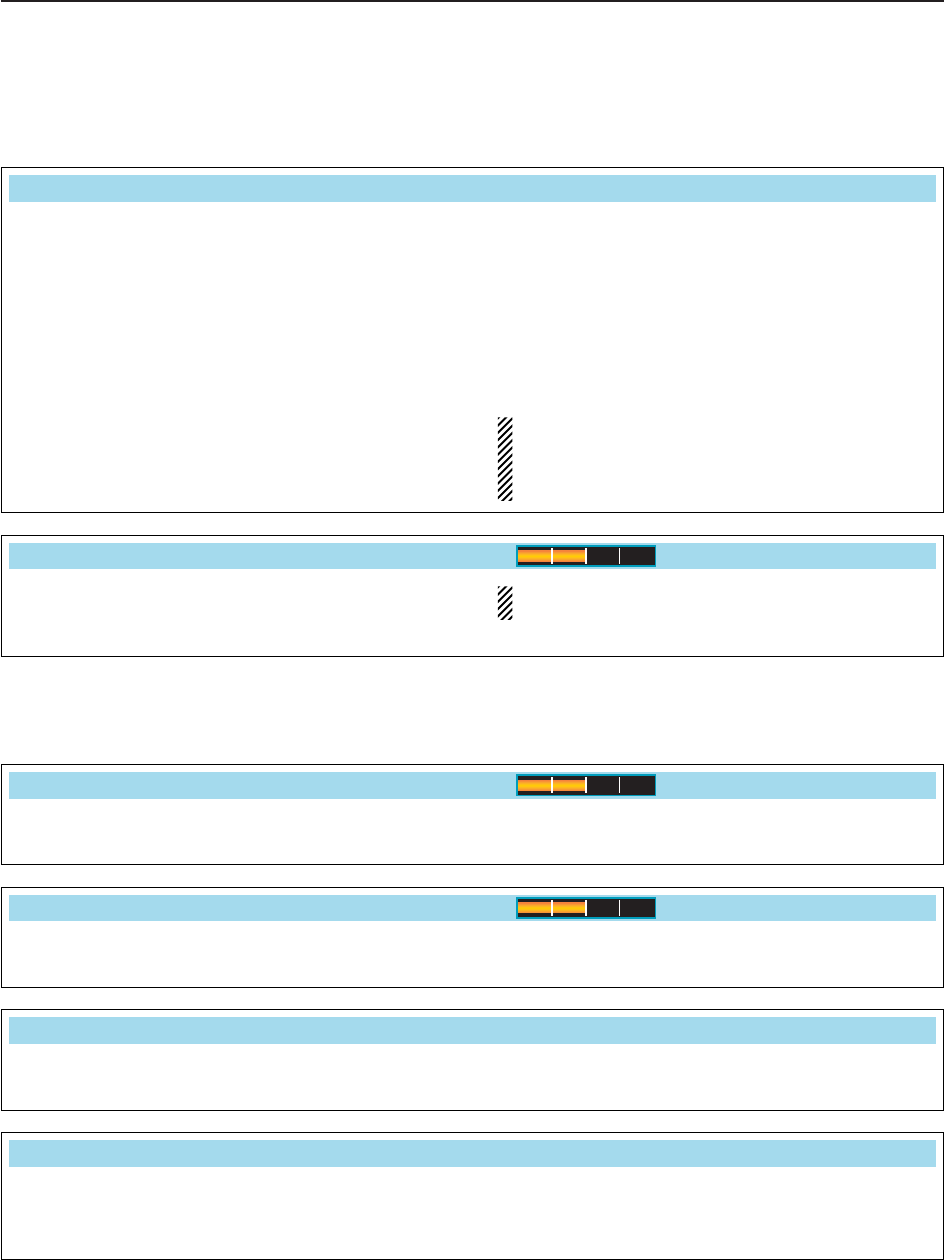
12-9
12
SET MODE
■ACC set mode (continued)
Selects the transceiver’s reference signal condition
from IN, OFF and OUT.
• IN : Use an external reference signal for the IC-
7700. Turn the transceiver power OFF then
ON to make the setting effective.
• OFF : Not input/output the reference signal.
(default)
• OUT : Outputs the IC-7700 reference signal to ex-
ternally connected equipment(s) for their ref-
erence.
NOTE: If the applied reference signal is off-fre-
quency, or no signal is applied with “IN” selection,
the IC-7700 will not work properly. Select “OFF” or
“OUT” then reboot the IC-7700 in such case.
REF IN/OUT
OFF
Adjusts the internal reference signal frequency within
0 to 100% range in 1% steps during frequency cali-
bration.
NOTE: Default setting is different for each trans-
ceiver.
REF Adjust
50%
■Display set mode
Adjusts the LCD unit brightness from 0 (dark) to 100%
(bright) range in 1% steps. (default: 50%)
LCD Unit Bright
50%
Adjusts the switch indicators brightness from 1 (dark)
to 100 (bright) range in 1 steps. (default: 80)
Backlight (Switches)
80
Selects the desired display type from A (Black back)
and B (Blue back). (default: A)
See p.13-4 for details.
Display Type
A
Selects the desired font for frequency readout from
Basic (1), Basic (2), Italic, Round and Slim.
(default: Basic (1))
See p.13-4 for details.
Display Font
Basic (1)

12-10
12 SET MODE
■Display set mode (continued)
Selects the desired S/RF meter type during normal
screen indication from Standard, Edgewise and Bar.
(default: Standard)
Meter Type (Normal Screen)
Standard
Selects the desired S/RF meter type during wide
screen or mini scope indication from Edgewise and
Bar. (default: Bar)
Meter Type (Wide Screen)
Bar
Turns the meter peak hold function ON and OFF.
(default: ON)
This function is used for the bar meter only.
Meter Peak Hold (Bar)
ON
Selects the pop-up display for the APF filter width
from ON and OFF.
(default: ON)
APF–Width Popup (APF OFF ON)
ON
Enables the pop-up indication capability when the
notch filter width is changed from ON to OFF.
(default: ON)
MN–Q Popup (MN OFF ON)
ON
Sets the memory name indication, during memory
mode operation, ON and OFF. (default: ON)
• ON : The programmed memory name is displayed
above the frequency indication.
• OFF : No memory name is displayed even a mem-
ory name is programmed.
Memory Name
ON
Set meter needle response from SLOW, MID and
FAST. (default: MID)
This setting is effective for the standard and edge-
wise meter type selections only.
Meter Response
MID

12-11
12
SET MODE
Select “ON” when the external display is connected.
(default: OFF)
• At least 800×600 pixel resolution is required for the dis-
play.
External Display
OFF
Selects the suitable pulse level for the connected ex-
ternal display from H and L. (default: H)
External Display Sync Pulse
H
Turns the opening message screen indication capa-
bility ON and OFF. (default: ON)
Opening Message
ON
■Display set mode (continued)
Turns the screen saver function ON (15, 30 or 60
minutes) and OFF. (default: 60 min.)
The screen saver will activate when no operation is
performed for the selected time period to protect the
LCD from the “burn-in” effect.
Screen Saver Function
60min
Selects the screen saver type from “Bound,” “Rota-
tion” and “Twist.” (default: Bound)
The screen saver indication can be displayed for your
reference while pushing and holding [PREVIEW] .
F-5
Screen Saver Type
Bound
Sets the introductory text, up to 10-character long,
displayed in the opening screen.
Usually, you set your call sign for the opening screen.
Capital letters, small letters, numerals, some symbols
(– / . @) and spaces can be used.
zPush [EDIT] to select the name edit condition.
• The cursor under the 1st character blinks.
xPush [ABC] (MF6), [abc] (MF6), [123] (MF7) or
[Symbol] (MF7) to select the character group, then
rotate the main dial to select the character.
• Push [ABC] (MF6) or [abc] (MF6) to toggle capital and
small letters.
• Push [123] (MF7) or [Symbol] (MF7) to toggle numerals
and symbols.
• Push [Ω] or [≈] for cursor movement.
• Push [DEL] to delete the selected character.
• Push [SPACE] to input a space.
• Pushing the transceiver’s keypad, [0]–[9], can also
enter numerals.
cPush to set the name.
EXIT/SET
F-4
F-3
F-2F-1
F-5
My Call

12-12
12 SET MODE
■Others set mode
This item is used for a simple frequency check of the
transceiver. (default: OFF)
See p. 13-5 for calibration procedure.
NOTE: Turn the calibration marker OFF after
checking the frequency of the transceiver.
Calibration Marker
OFF
A beep sounds each time a switch is pushed to con-
firm it. This function can be turned OFF for silent op-
eration. (default: ON)
The beep output level can be set in level set mode.
(p. 12-6)
Beep (Confirmation)
ON
A beep sounds when an operating frequency enters
or exits an amateur band. This functions independent
of the confirmation beep setting (above). (default: ON)
The beep output level can be set in level set mode.
(p. 12-6)
Beep (Band Edge)
ON
Sets the desired key-touch beep sound frequency
within 500 to 2000 Hz in 10 Hz steps. (default:
1000 Hz)
Beep Sound
1000Hz
When this item is set to ON, pushing and holding
for 1 sec. sets the unselected VFO’s readout
frequency to the selected VFO’s readout frequency
and activates split operation.
(default: ON)
See p. 6-7 for details.
SPLIT
Quick SPLIT
ON

12-13
12
SET MODE
■Others set mode (continued)
Sets the offset (difference between transmit and re-
ceive frequencies) for the quick split function. This set-
ting is used for HF bands in FM mode only and is
used to input the repeater offset for an HF band.
The offset frequency can be set from –9.999 MHz to
+9.999 MHz in 1 kHz steps. (default: –0.100 MHz)
FM SPLIT Offset(HF)
–0.100MHz
Sets the offset (difference between transmit and re-
ceive frequencies) for the quick split function. This set-
ting is used for 50 MHz band FM mode only, and is
used to input the repeater offset for the 50 MHz band.
The offset frequency can be set from –9.999 MHz to
+9.999 MHz in 1 kHz steps. (default: –0.500 MHz)
FM SPLIT Offset(50M)
–0.500MHz
When this item is ON, the main dial can be used to
adjust the transmit frequency while pushing [XFC]
even while the lock function is activated.
(default: OFF)
See pgs. 6-6, 6-7 for split frequency operation details.
SPLIT LOCK
OFF
The internal antenna tuner has an automatic start ca-
pability which starts tuning if the SWR is higher than
1.5–3:1.
• OFF : The tuner remains OFF even when the SWR
is poor (1.5–3:1). (default)
• ON : Automatic tune starts even when the tuner is
turned OFF during HF bands operation.
Tuner (Auto Start)
OFF
Tuning of the internal antenna tuner can be started
automatically at the moment the PTT is pushed after
the operating frequency is changed (more than 1%
from last-tuned frequency). (default: OFF)
Tuner (PTT Start)
OFF

12-14
12 SET MODE
Selects the transverter operation condition from Auto
and ON. (default: Auto)
• ON : Turn the transverter operation ON.
• Auto : The transceiver turns into transverter opera-
tion condition when 2 to 13.8 V DC is applied
to [ACC2] pin 6.
Transverter Function
Auto
Sets the desired offset frequency for the transverter
operation within 0.000 to 99.999 MHz in 1 kHz steps.
(default: 16.000 MHz)
Transverter Offset
16.000MHz (14.000.00 30.000.00)
■Others set mode (continued)
Selects the RTTY mark frequency. RTTY mark fre-
quency is switched between 1275, 1615 and
2125 Hz. (default: 2125 Hz)
2125 Hz is automatically selected when the internal
RTTY decoder is used.
RTTY Mark Frequency
2125
Selects the RTTY shift width. There are 3 selectable
values: 170, 200 and 425 Hz. (default: 170 Hz)
170 Hz is automatically selected when the internal
RTTY decoder is used.
RTTY Shift Width
170
Selects the RTTY keying polarity. Normal or reverse
keying polarity can be selected.
(default: Normal)
When reverse polarity is selected, Mark and Space
are reversed.
• Normal : Key open/close = Mark/Space
• Reverse : Key open/close = Space/Mark
RTTY Keying Polarity
Normal
Selects the desired PSK tone frequency for the PSK
reception from 1000, 1500 and 2000 Hz.
(default: 1500 Hz)
PSK Tone Frequency
1500
Selects the speech language from English and Japan-
ese. (default: English)
SPEECH Language
English
Selects the speech speed from HIGH (faster) and
LOW (slower). (default: HIGH)
SPEECH Speed
HIGH

12-15
12
SET MODE
■Others set mode (continued)
Sets the auto tuning step function for the main dial.
When rotating the main dial rapidly, the tuning step
automatically changes several times as selected.
There are 2 type of auto tuning steps: HIGH (Fastest)
and LOW (Faster). (default: HIGH)
• HIGH : Auto tuning step is turned ON. Fastest tun-
ing step during rapid rotation. (default)
• LOW : Auto tuning step is turned ON. Faster tun-
ing step during rapid rotation.
• OFF : Auto tuning step is turned OFF.
MAIN DIAL Auto TS
HIGH
Sets the number of memo pad channels available. 5
or 10 memo pads can be set. (default: 5)
Memopad Numbers
5
The IC-7700 speech processor has frequency, mode
and signal level announcement. Signal level an-
nouncement can be deactivated if desired.
(default: ON)
When “OFF” is selected, the signal level is not an-
nounced.
SPEECH S-Level
ON
Selects the operating mode speech capability when a
mode switch is pushed; ON or OFF.
(default: OFF)
When “ON” is selected, the selected operating mode
is announced when a mode switch is pushed.
SPEECH [MODE] Switch
OFF
Sets the rate at which frequencies are scanned when
the microphone [UP]/[DN] switches are pushed and
held. High or low can be selected.
• HIGH : High speed (default; 50 tuning steps/sec.)
• LOW : Low speed (25 tuning steps/sec.)
MIC Up/Down Speed
HIGH
Selects the RIT/∂TX frequency clearing instruction
with the switch.
• ON : Clears the RIT/∂TX frequency when
is pushed momentarily.
• OFF : Clears the RIT/∂TX frequency when
is pushed and held for 1 sec.
(default)
CLEAR
CLEARCLEAR
Quick RIT/∂TX Clear
OFF

■Others set mode (continued)
12-16
12 SET MODE
Selects [DIGI-SEL] control function from DIGI-SEL
and APF.
• DIGI-SEL : [DIGI-SEL] control functions as the digi-
tal selector operation. (default)
• APF : [DIGI-SEL] control functions as the
audio peak filter adjustment.
DIGI–SEL VR Operation
DIGI–SEL
Selects notch functions for SSB mode operation from
Auto, Manual and Auto/Manual.
• Auto : Only the auto notch can be used.
• Manual : Only the manual notch can be used.
• Auto/Manual : Both the auto and manual notch can
be used. (default)
[NOTCH] Switch (SSB)
Auto/Manual
Selects notch functions for AM mode operation from
Auto, Manual and Auto/Manual.
• Auto : Only the auto notch can be used.
• Manual : Only the manual notch can be used.
• Auto/Manual : Both the auto and manual notch can
be used. (default)
[NOTCH] Switch (AM)
Auto/Manual
Selects the displayed frequency shift function from
ON and OFF. (default: OFF)
When this function is activated, the audio pitch or
tones of the received signal will remain the same
even when the operating mode is changed between
SSB and CW.
The frequency shifting value may differ according
to the CW pitch setting.
• ON : The displayed frequency shifts when the op-
erating mode is changed between SSB and
CW.
• OFF : The displayed frequency does not shift.
SSB/CW Synchronous Tuning
OFF
Selects the side band used to receive CW in CW nor-
mal mode. (default: LSB)
CW Normal Side
LSB
Set audio filter shape for APF from SOFT and
SHARP. (default: SOFT)
• SOFT : Soft filter shape makes distinguishing
noise and signals easier. The audio filter
width is related to the CW pitch setting.
• SHARP : Sharp filter shape rejects interference
signals.
APF Type
SHARP

12-17
12
SET MODE
Sets the external keypad for voice message trans-
mission capability ON and OFF.
See page 2-7 for the equivalent circuit of an external
keypad and connection.
• ON : Pushing one of external keypad switches,
transmits the desired voice message contents
during a phone mode operation.
• OFF : External keypad does not function. (default)
External Keypad (VOICE)
OFF
Sets the external keypad for keyer memory transmis-
sion capability ON and OFF.
See page 2-7 for the equivalent circuit of an external
keypad and connection.
• ON : Pushing one of external keypad switches,
transmits the desired keyer memory contents
during CW mode operation.
• OFF : External keypad does not function. (default)
External Keypad (KEYER)
OFF
■Others set mode (continued)
Transceive operation is possible with the IC-7700
connected to other Icom HF transceivers or receivers.
When “ON” is selected, changing the frequency, op-
erating mode, etc. on the IC-7700 automatically
changes those of connected transceivers (or re-
ceivers) and vice versa.
CI–V Transceive
ON
To distinguish equipment, each CI-V transceiver has
its own Icom standard address in hexadecimal code.
The IC-7700’s address is 74h.
When 2 or more IC-7700’s are connected to an op-
tional CT-17 CI-V LEVEL CONVERTER, rotate the main dial
to select a different address for each IC-7700; the
range is 01h to 7Fh.
CI–V Address
74h
Sets the CI-V data transfer rate. 300, 1200, 4800,
9600, 19200 bps and “Auto” are available. (default:
Auto)
When “Auto” is selected, the baud rate is automati-
cally set according to the data rate of connected con-
troller.
CI–V Baud Rate
Auto

12-18
12 SET MODE
■Others set mode (continued)
Select [RS-232C] connector output data format from
CI-V and Decode.
• CI-V : Outputs data in CI-V format. (default)
• Decode : Outputs decoded contents in ASCII code
format.
RS–232C Function
CI–V
Selects data transmission speed (Baud rate) when
“Decode” is selected in “RS-232C Function” above;
settings are 300, 1200, 4800, 9600 and 19200 bps.
(default: 9600)
Decode Baud Rate
9600
Selects the connected keyboard type from Japanese,
English, United Kingdom, French, French (Canadian),
German, Portuguese, Portuguese (Brazilian), Span-
ish, Spanish (Latin American) and Italian.
(default: English)
Keyboard Type
English
Sets the time period for delay within 100 to
1000 msec. in 50 msec. steps. (default: 250 msec.)
When a key of the connected keyboard is pressed
and held for the set period, the character is input con-
tinuously.
Keyboard Repeat Delay
250ms
Sets subnet mask for the IC-7700 when connecting
to your PC or LAN (Local Area Network) through the
Ethernet connector.
Turn the transceiver power OFF then ON to make the
setting effective. See p. 16-7 for details.
Subnet Mask (Valid after Reboot)
255. 255. 255. 0 (24bit)
Sets the repeating rate for the connected keyboard
within 2.0 to 30.0 cps. (default: 10.9 cps)
*cps=character per second
When a key of the connected keyboard is pressed
and held, the character is repeatedly input with the set
speed.
• Available repeating rate
2.0, 2.1, 2.3, 2.5, 2.7, 3.0, 3.3, 3.7, 4.0, 4.3, 4.6, 5.0,
5.5, 6.0, 6.7, 7.5, 8.0, 8.6, 9.2, 10.0, 10.9, 12.0,
13.3, 15.0, 16.0, 17.1, 18.5, 20.0, 21.8, 24.0, 26.7,
30.0
Keyboard Repeat Rate
10.9cps
Sets IP address for the IC-7700 when connecting to
your PC or LAN (Local Area Network) through the
Ethernet connector.
Turn the transceiver power OFF then ON to make the
setting effective. See p. 16-7 for details.
IP Address (Valid after Reboot)
192. 168. 0. 1
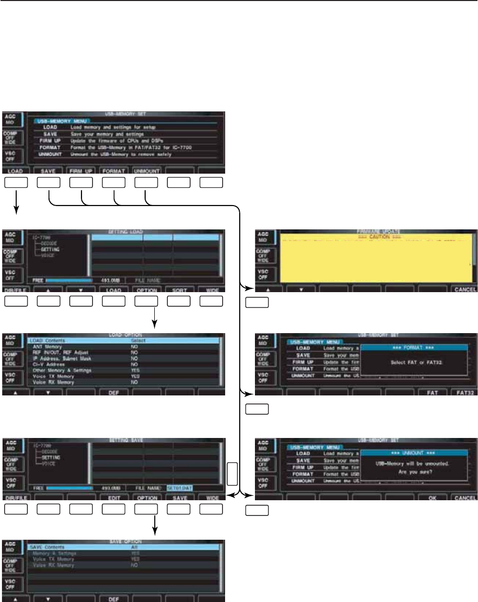
12-19
12
SET MODE
■USB-Memory set menu
D
USB-Memory set screen arrangement
• USB-Memory set menu
• Setting load screen (p. 12-23)
• Load option set mode (p. 12-21)
• Firmware update (p. 16-4)
• Format menu (p. 12-26)
• Setting save screen (p. 12-22)
• Save option set mode (p. 12-20)
F-1 F-2 F-3 F-4
F-3
F-4
F-2
F-5 F-6 F-7
F-1 F-2 F-3 F-4 F-5 F-6 F-7
F-1 F-2 F-3 F-4 F-5 F-6 F-7
• Unmount USB-Memory (p. 12-25)
F-5
Updating the firmware is very risky. If you make a mistake, the IC-77Updating the firmware is very risky. If you make a mistake, the IC-7700 may00 may
not operate properly, and repair at Icom Inc, (Japan) may be the only way to
fix it.
You undertake the updating of the firmware at your own risk and responsibility.
Please refer to the firmware download homepage and/or the instruction manual
for the correct procedures in updating the firmware.

D
Save option set mode
12-20
12 SET MODE
Selects file save condition from All and Select.
(default: All)
• All : Saves all the following contents.
• Select : Saves the selected contents only.
SAVE Contents
All
This setting is fixed “YES.” • YES : Saves memory channel contents and set-
tings of set modes.
Memory & Settings
YES
Selects the voice TX message save condition from
YES and NO. (default: YES)
• YES : Saves the voice TX message.
• NO : Does not save.
Voice TX Memory
YES
Selects the voice RX message save condition from
YES and NO. (default: NO)
• YES : Saves the voice RX message.
• NO : Does not save.
Voice RX Memory
NO

12-21
12
SET MODE
D
Load option set mode
Selects file load condition from All and Select.
(default: Select)
• All : Loads and sets the all following contents.
• Select : Loads and sets the selected contents only.
Load Contents
Select
Selects the antenna memory setting loading condition
YES and NO. (default: NO).
• YES : Loads and sets the antenna memory.
• NO : Use the original antenna memory setting.
ANT Memory
NO
Selects the reference signal setting load condition
YES and NO. (default: NO).
• YES : Loads and sets the reference signal setting.
• NO : Use the original reference signal setting.
REF IN/OUT, REF Adjust
NO
Selects the IP address and subnet mask setting load
condition YES and NO. (default: NO).
• YES : Loads and sets the IP address and subnet
mask setting.
• NO : Use the original IP address and subnet
mask setting.
IP Address, Subnet Mask
NO
Selects the CI-V address setting load condition YES
and NO. (default: NO).
• YES : Loads and sets the CI-V address setting.
• NO : Use the original CI-V address setting.
CI–V Address
NO
Selects memory channel contents and other settings
load condition YES and NO. (default: YES).
• YES : Loads and sets memory channel contents
and other settings.
• NO : Use the original memory channel contents
and other settings.
Other Memory & Settings
YES
Selects the voice TX message load condition YES
and NO. (default: YES).
• YES : Loads and sets voice TX message.
• NO : Use the original voice TX message.
Voice TX Memory
YES
Selects the voice RX message load condition YES
and NO. (default: NO).
• YES : Loads and sets voice RX message.
• NO : Use the original voice RX message.
Voice RX Memory
YES
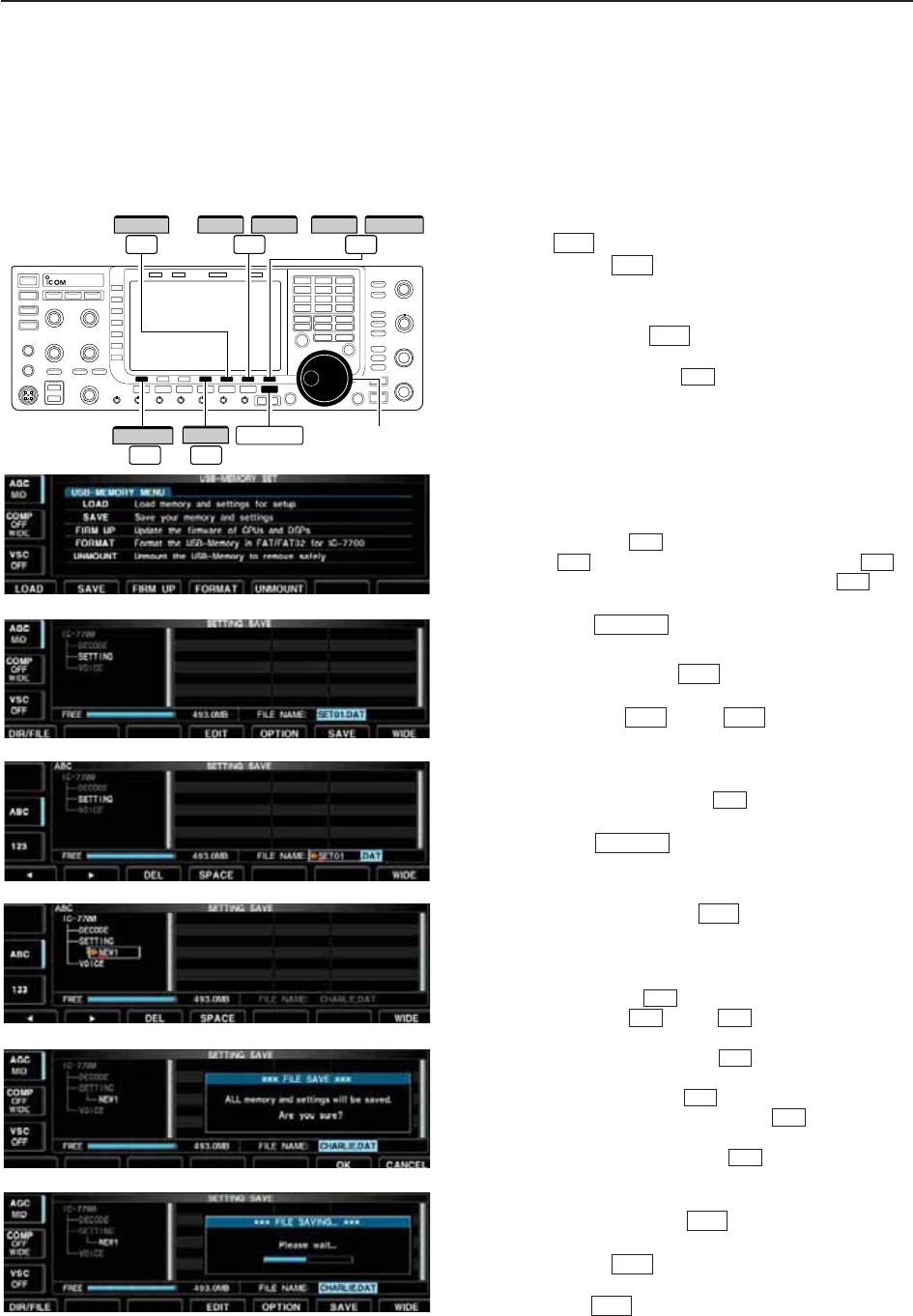
12-22
12 SET MODE
■File saving
Memory channel contents, set mode settings, etc. can
be saved into the USB-Memory for backup.
q
During set mode menu screen indication, push
[USB] to select USB-Memory set menu screen.
wPush [SAVE] to select setting save screen.
eChange the following conditions if desired.
• File name:
zPush [EDIT] to select file name edit con-
dition.
• Push [DIR/FILE] several times to select the
file name, if necessary.
xPush [ABC] (MF6), [123] (MF7) or [Symbol]
(MF7) to select the character group, then ro-
tate the main dial to select the character.
• [ABC] (MF6): A to Z (capital letters); [123] (MF7): 0
to 9 (numerals); [Symbol] (MF7): ! # $ % & ‘ ` ^ + –
= ( ) [ ] { } _ ~ @ can be selected.
• Push [Ω] to move the cursor left, push [≈]
to move the cursor right, push [DEL] to
delete a character and push [SPACE] to in-
sert a space.
cPush to set the file name.
• Save option
zPush [OPTION] to enter save option set
mode.
xPush [Y] or [Z] to select the item,
then rotate the main dial to select the desired
setting. (see p. 12-20 for details)
• “Text” is the default setting.
• Push and hold [DEF] for 1 sec. to select the
default setting.
cPush to return to the previous indi-
cation.
• Saving location
zPush [DIR/FILE] to select tree view
screen.
xSelect the desired directory or folder in the
USB-Memory.
• Push [Ω≈] to select the upper directory.
• Push [Y] or [Z] to select folder in the
same directory.
• Push and hold [Ω≈] for 1 sec. to select a
folder in the directory.
• Push [REN/DEL] to rename the folder.
• Push and hold [REN/DEL] for 1 sec. to
delete the folder.
• Push and hold [MAKE] for 1 sec. to making
a new folder. (Edit the name with the same man-
ner as the “• File name” above.)
cPush [DIR/FILE] twice to select the file
name.
rPush [SAVE] .
• Confirmation screen appears.
tPush [OK] to save.
• After saving is completed, return to USB-Memory set
menu automatically.
F-6
F-6
F-1
F-6
F-5
F-5
F-4
F-3F-2
F-4
F-1
EXIT/SET
F-4
F-2F-1
F-5
EXIT/SET
F-4
F-3F-2
F-1
F-1
F-4
F-2
F-7
Main dial
DIR/FILE EXIT/SET
F-1
F-7
WIDE CANCEL
F-5
OPTION
F-6
SAVE OK
F-4
EDIT
//
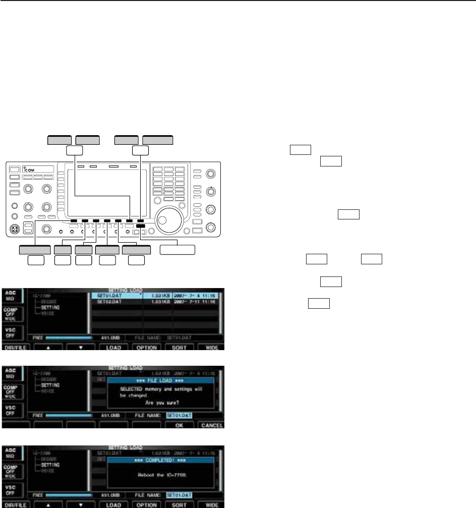
12-23
12
SET MODE
■File loading
By loading the saved setting file from the USB-Mem-
ory, you can easily set up another IC-7700—several
operators settings can easily be applied to one IC-
7700.
qDuring set mode menu screen indication, push
[USB] to select USB set menu screen.
wPush [LOAD] to select setting load screen.
• The indicator above the USB connectors and “USB” in-
dicator on the display blink.
• After the USB-Memory contents are displayed, the indi-
cators stop blinking.
ePush [OPTION] to select load option set
mode, then set the desired loading conditions, if de-
sired.
• See page 12-21 for details.
rPush [Y] or [Z] to select the desired
setting file.
tPush [LOAD] .
• Confirmation screen appears.
yPush [OK] to starts loading.
• After the loading is completed, the message dialog, “Re-
boot the IC-7700,” appears.
uTurn the transceiver power OFF then ON to make
the setting effective.
F-6
F-4
F-3F-2
F-5
F-1
F-7
DIR/FILE
F-1
F-7
WIDE CANCEL
F-5
OPTION
F-6
SORT OK
F-4
LOAD
//
F-2
∫
F-3
√EXIT/SET
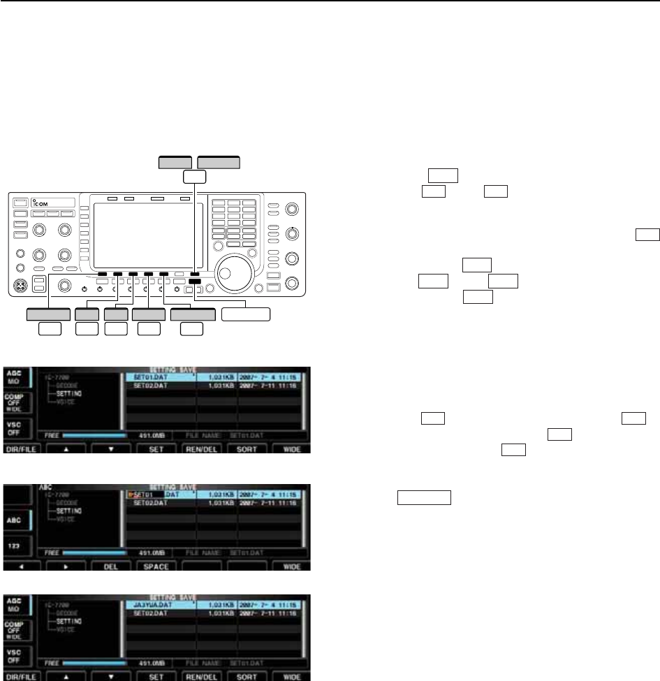
■Changing a file name
The file name, saved in the USB-Memory, can be re-
named from the transceiver as desired.
qDuring setting save screen display, push
[DIR/FILE] to select tree view screen.
• Push [Y] or [Z] to select the desired folder.
• “DECODE,” “SETTING” and “VOICE” folders are avail-
able as the default.
• After the folder is selected, push and hold [Ω≈]
for 1 sec. to display content folder(s), if available.
wPush [DIR/FILE] to select file list screen.
ePush [Y] or [Z] to select the desired file.
rPush [REN/DEL] momentarily to select the file
name edit condition.
tPush [ABC] (MF6), [123] (MF7) or [Symbol] (MF7) to
select the character group, then rotate the main dial
to select the character.
• [ABC] (MF6): A to Z (capital letters); [123] (MF7): 0 to 9
(numerals); [Symbol] (MF7): ! # $ % & ‘ ` ^ + – = ( ) [ ] { }
_ ~ @ can be selected.
• Push [Ω] to move the cursor left, push [≈] to
move the cursor right, push [DEL] to delete a char-
acter and push [SPACE] to insert a space.
• Pushing the transceiver’s keypad, [0]–[9], can also enter
numerals.
yPush to set the file name.
EXIT/SET
F-4
F-3
F-2F-1
F-5
F-3F-2
F-1
F-4
F-3F-2
F-1
DIR/FILE
F-1
F-7
WIDE CANCEL
REN/DEL
F-5
F-4
Ω ≈
/
F-2
∫
F-3
√EXIT/SET
12-24
12 SET MODE
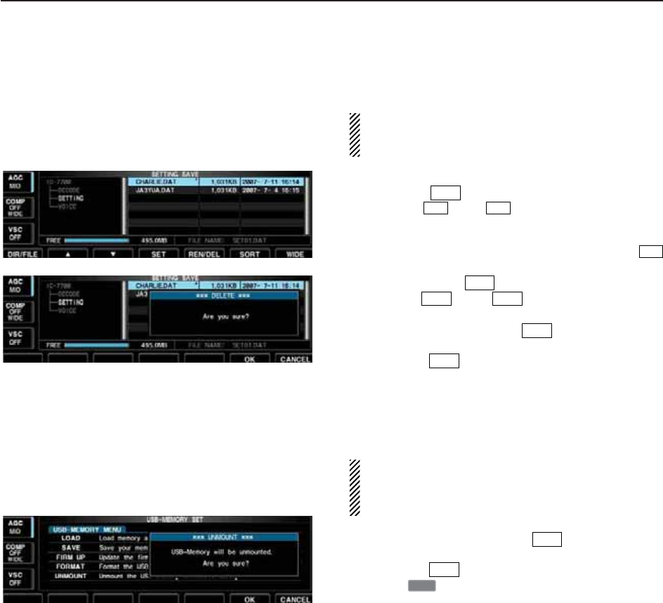
12-25
12
SET MODE
■Deleting a file
RECOMMENDATION! Deleting the setting file is ir-
reversible. Confirm the contents before deleting a
setting file!
qDuring setting save screen display, push
[DIR/FILE] to select tree view screen.
• Push [Y] or [Z] to select the desired folder.
• “DECODE,” “SETTING” and “VOICE” folders are avail-
able as the default.
• After the folder is selected, push and hold [Ω≈]
for 1 sec. to display content folder(s), if available.
wPush [DIR/FILE] to select file list screen.
ePush [Y] or [Z] to select the desired file
to be deleted.
rPush and hold [REN/DEL] for 1 sec.
• Confirmation screen appears.
tPush [OK] to delete.
• After the deleting, return to setting save screen auto-
matically.
■Unmounting USB-Memory
CAUTION! When removing the USB-Memory, un-
mount operation is necessary. If you do not unmount
the memory in this case, data in the USB memory
may be corrupted.
qPush and hold [UNMOUNT] for 1 sec.
• Confirmation screen appears.
wPush [OK] to unmount the USB-Memory.
eAfter “ ” indication disappears, remove the
USB-Memory.
USB
F-6
F-6
F-6
F-5
F-3F-2
F-1
F-4
F-3F-2
F-1
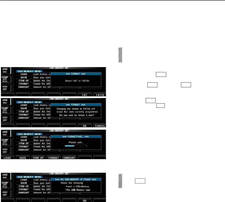
12-26
12 SET MODE
■Formatting the USB-Memory
Saved data in the USB-Memory can be erased.
IMPORTANT! Formatting erases all saved data in
the USB-Memory. Making a backup file on your PC
is recommended.
qDuring USB-Memory set menu display, push and
hold [FORMAT] for 1 sec.
• Confirmation screen appears.
wPush [FAT] or [FAT32] to select the for-
mat type, FAT or FAT32, respectively.
• Confirmation screen appears.
ePush [OK] to format.
• Push [CANCEL] to cancel.
rReturns to USB-Memory set menu indication auto-
matically.
NOTE: If no USB-Memory is inserted and [FOR-
MAT] is selected as in step q, an error mes-
sage appears.
F-4
F-7
F-6
F-7F-6
F-4

13-1
MAINTENANCE Section 13
■Troubleshooting ……………………………………………………… 13-2
DTransceiver power ………………………………………………… 13-2
DTransmit and receive ……………………………………………… 13-2
DScanning …………………………………………………………… 13-3
DDisplay ……………………………………………………………… 13-3
DFormat USB-Memory ……………………………………………… 13-3
■Main dial brake adjustment ………………………………………… 13-3
■SWR reading …………………………………………………………… 13-4
■Screen type and font selections …………………………………… 13-4
■Frequency calibration (approximate) ……………………………… 13-5
■Opening the transceiver’s case ……………………………………… 13-6
■Clock backup battery replacement ………………………………… 13-6
■Fuse replacement …………………………………………………… 13-7
■Resetting the CPU …………………………………………………… 13-7
■About protection indications ………………………………………… 13-8
■Screen Saver Function ……………………………………………… 13-8

■Troubleshooting
The following chart is designed to help you correct
problems which are not equipment malfunctions.
If you are unable to locate the cause of a problem or
solve it through the use of this chart, contact you near-
est Icom Dealer or Service Center.
D
Transceiver power
D
Transmit and receive
PROBLEM POSSIBLE CAUSE SOLUTION REF.
No sounds from the
speaker.
Sensitivity is too low, and
only strong signals are
audible.
Received audio is unclear
or distorted.
The [ANT] switch does not
function
Transmitting is impossible.
Output power is too low.
No contact possible with
another station.
Transmit signal is unclear
or distorted.
Repeater cannot be
accessed.
• Volume level is too low.
• The squelch is closed.
• The transceiver is in transmit.
• The antenna is not connected properly.
• The antenna for another band is selected.
• The antenna is not properly tuned.
• The attenuator is activated.
• Wrong operating mode is selected.
• PBT function is activated.
• Noise blanker is turned ON when receiving a
strong signal.
• Preamp is activated.
• The noise reduction is activated and the [NR]
control is too far clockwise.
• The antenna switch has not been activated.
• The operating frequency is not inside a ham
band.
• [RF PWR] is set too far counterclockwise
• [DRIVE] is set too far counterclockwise
• [MIC] is set too far counterclockwise
• The antenna for another band is selected.
• The antenna is not properly tuned.
• RIT or ∂TX function is activated.
• Split frequency function is activated.
• [MIC] is set too far clockwise
• Split frequency function is not activated.
• Programmed subaudible tone frequency is
wrong.
• Rotate [AF] clockwise to obtain a suitable lis-
tening level.
• Turn [SQL] to 10 o’clock position to open the
squelch.
• Push [TRANSMIT] to receive or check the
SEND line of an external unit, if connected.
• Re-connect to the antenna connector.
• Select an antenna suitable for the operating
frequency.
• Push and hold [TUNER] for 1 sec. to manually
tune the antenna.
• Push [ATT] (MF4) several times to select “ATT
OFF.”
• Select a suitable operating mode.
• Push and hold [PBT-CLR] for 1 sec. to reset the
function.
• Push [NB] to turn the noise blanker OFF.
• Push [P.AMP] (MF3) once or twice to turn the
function OFF.
• Set the [NR] control for maximum readability.
• Set the antenna switch in set mode to “Auto” or
“Manual.”
• Set the frequency to be in a ham band.
• Rotate [RF PWR] clockwise.
• Set [DRIVE] to a suitable position.
• Set [MIC] to a suitable position.
• Select an antenna suitable for the operating
frequency.
• Push and hold [TUNER] for 1 sec. to manually
tune the antenna.
• Push [RIT] or [∂TX] to turn the function OFF.
• Push [SPLIT] to turn the function OFF.
• Set [MIC] to a suitable position.
• Push [SPLIT] to to turn the function ON
• Reset the frequency using set mode.
p. 3-9
p. 3-9
p. 3-12
—
p. 10-2
p. 10-6
p. 5-9
p. 3-8
p. 5-12
p. 5-16
p. 5-9
p. 5-17
p. 10-4
p. 3-5
p. 3-12
p. 3-13
p. 3-12
p. 10-2
p. 10-6
pgs. 5-10,
6-4
p. 6-6
p. 3-12
p. 6-6
p. 4-33
PROBLEM POSSIBLE CAUSE SOLUTION REF.
13-2
13 MAINTENANCE
Power does not come on
when the [POWER] switch
is pushed.
• Power cable is improperly connected.
• The internal power supply is turned OFF.
• Circuit breaker is tripped.
• Re-connect the AC power cable correctly.
• Turn the internal power supply ON.
• Check for the cause, then re-set the circuit
breaker.
p. 2-5
p. 3-2
—
13-3
D
Scanning
D
Display
D
Format USB-Memory
13
MAINTENANCE
PROBLEM POSSIBLE CAUSE SOLUTION REF.
Programmed scan does
not stop.
Programmed scan does
not start.
Memory scan does not
start
Select memory scan does
not start
• Squelch is open.
•
The same frequencies have been programmed
in scan edge memory channels P1 and P2.
• 2 or more memory channels have not been
programmed.
• 2 or more memory channels have not been
designated as select channels.
• Set [SQL] to the threshold point.
• Program different frequencies in scan edge
memory channel P1 and P2.
• Program more than 2 memory channels.
• Designate more than 2 memory channels as
select channels for the scan.
p. 3-9
p. 8-3
p. 8-3
p. 9-7
PROBLEM POSSIBLE CAUSE SOLUTION REF.
The displayed frequency
does not change properly.
• The dial lock function is activated.
• A set mode screen is selected.
• The internal CPU has malfunctioned.
•
Push [LOCK] to turn the function OFF.
• Push [EXIT/SET] several times to exit the set
mode screen.
• Reset the CPU.
p. 5-17
p. 12-2
p. 13-7
■Main dial brake adjustment
The tension of the main dial may be adjusted to suit
your preference.
The brake adjustment is located on the bottom side of
the front panel. See the figure at left.
Slide the brake adjustment to a comfortable tension
level while turning the dial continuously and evenly in
one direction.
Light
Heavy
[MAIN DIAL]
Brake
adjustment
PROBLEM POSSIBLE CAUSE SOLUTION REF.
Format error appears
when formatting in FAT32
Format error appears
when formatting in FAT
• The inserted USB-Memory capacity is smaller
than 64 MB.
• The inserted USB-Memory capacity is larger
than 2 GB.
•
Insert a
USB-Memory
larger than 64 MB or
select the FAT format.
•
Insert a
USB-Memory
smaller than 2 GB or
select the FAT32 format.
p. 12-26
p. 12-26
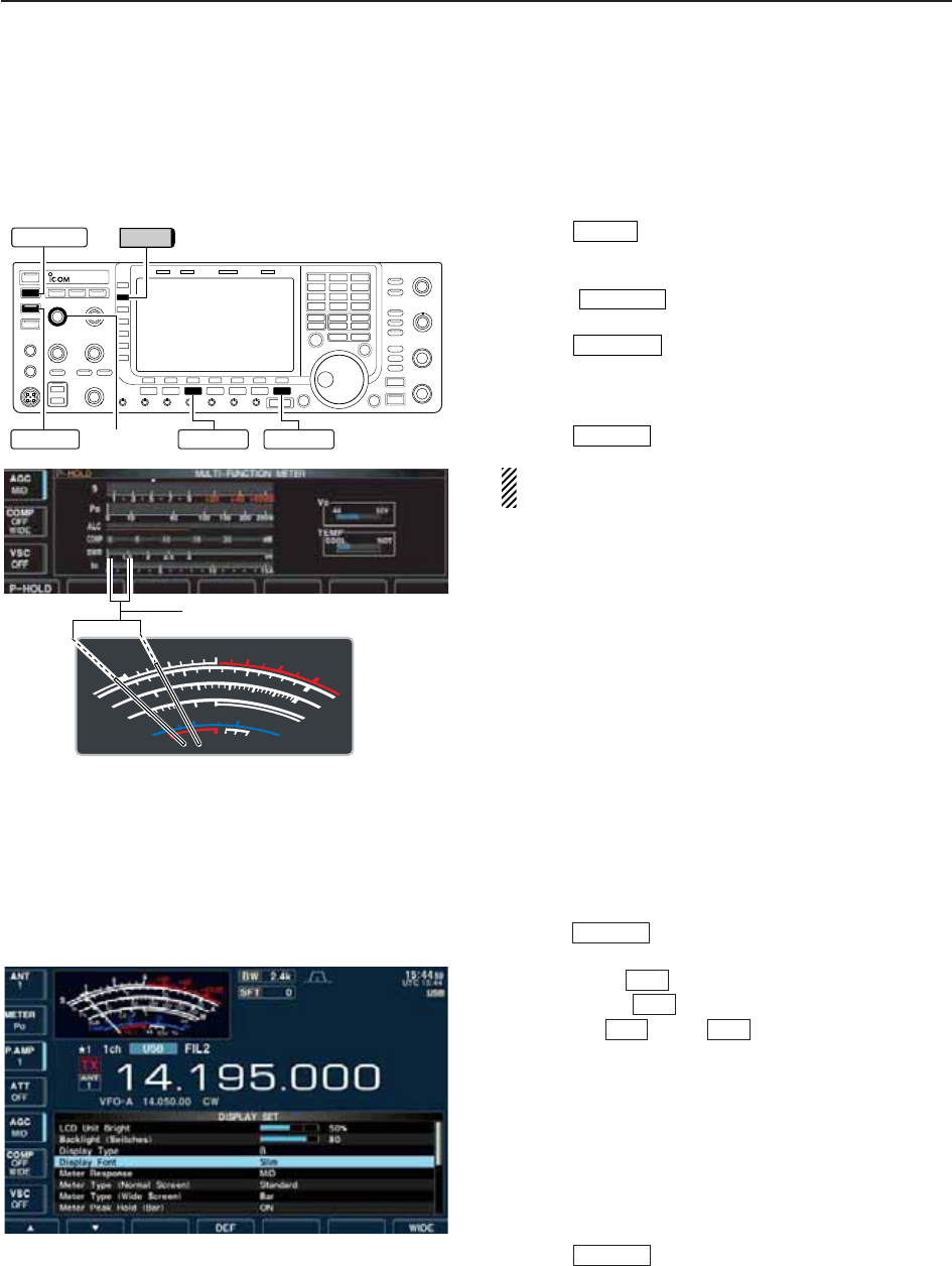
13-4
■SWR reading
The SWR meter indicates the SWR over the transmis-
sion line in all modes.
qPush to turn the antenna tuner OFF.
wPush and hold [METER] for 1 sec. to display multi-
function meter.
ePush once or twice to select RTTY
mode.
rPush .
tRotate [RF PWR] clockwise past the 12 o’clock po-
sition for more than 30 W output power.
yRead the SWR on the SWR meter gage.
uPush to close multi-function meter.
The built-in antenna tuner matches the transmitter
to the antenna when the SWR is lower than 3 : 1.
■Screen type and font selections
2 types of screen images and 5 types of frequency
readout indication fonts are available in the IC-7700.
qPush several times to close multi-function
screen, if necessary.
wPush [SET] to select set mode menu screen.
ePush [DISP] to enter display set mode.
rPush [Y] or [Z] to select “Display Type”
item when selecting the screen image, select “Dis-
play Font” when selecting the frequency readout in-
dication font.
tRotate the main dial to select the desired screen
image or font.
• Screen image is selectable from A (Black back) and B
(Blue back).
• Basic (1), Basic (2), Italic, Round and Slim are available
for the frequency readout font.
yPush twice to exit from display set mode.
EXIT/SET
F-2F-1
F-3
F-7
EXIT/SET
EXIT/SET
TRANSMIT
RTTY/PSK
TUNER
S
1
0
0
0
1
2
510
10
10 20
44 52V
50 100 150 200 250
15
3
1.5
ID
VD
dB
WA
Po
SWR
COMP ALC
59+20 +40 +60dB
∞
Better than 1.5:1
[RF PWR] RTTY/PSK EXIT/SETTUNER
TRANSMIT METER
13 MAINTENANCE
• Screen image example—
Display Type: B, Display Font: Slim
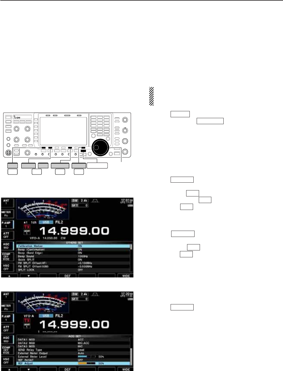
13-5
■Frequency calibration (approximate)
A very accurate frequency counter is required to cali-
brate the frequency of the transceiver. However, a
rough check may be performed by receiving radio sta-
tion WWV, WWVH, or other standard frequency sig-
nals.
CAUTION: The IC-7700 has been thoroughly ad-
justed and tested at the factory before being
shipped. You should not have to re-calibrate it.
qPush to select USB mode.
wPush and hold for 1 sec. to clear the
PBT setting and make sure that the RIT/∂TX func-
tion is not activated.
eSet the frequency to the standard frequency station
minus 1 kHz.
• When receiving WWV or WWVH (at 15.00000 MHz) as
a standard frequency, set the operating frequency for
14.99900 MHz.
• Other standard frequencies can be used.
rPush several times to close a multi-func-
tion screen, if necessary.
• Calibration marker item tPush [SET] to select set mode menu screen.
yPush [OTHERS] to enter Others set mode.
uPush [Y] several times to select the “Calibra-
tion Marker” item.
iRotate the main dial clockwise to turn the calibra-
tion marker ON.
oPush once to return to set mode menu
screen.
!0 Push [ACC] to enter accessory set mode.
!1 Push [Z] several times to select the “REF Ad-
just” item.
!2 Rotate the main dial to adjust for a zero beat with
the received standard signal as shown at left.
• REF Adjust item
• Zero beat means that two signals are exactly the same
frequency, resulting in a single tone being emitted.
!3 Turn the calibration marker OFF in Others set
mode.
!4 Push twice to exit set mode.
EXIT/SET
F-2
F-2
EXIT/SET
F-1
F-5
F-7
EXIT/SET
PBT-CLR
SSB
Main dial
F-2F-1
ACC
F-5
OTHERS EXIT/SET
F-7
SET
/
∫ √
13
MAINTENANCE
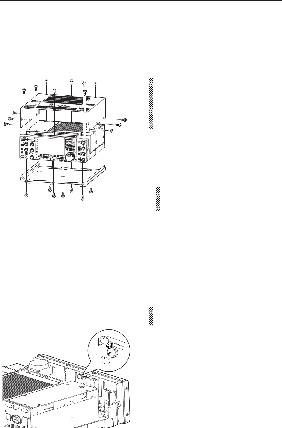
13-6
■Opening the transceiver’s case
Follow the case opening procedures shown here when
you want to replace the clock backup battery or inter-
nal fuse.
CAUTION!: DISCONNECT the AC power cable
from the transceiver before performing any work on
the transceiver. Otherwise, there is danger of elec-
tric shock and/or equipment damage.
CAUTION!: The transceiver weighs approx. 24 kg
(53 lb). Always have two people available to lift or
turn over the transceiver.
qRemove the rack mounting handle from both side.
See p. 2-3 for rack mounting handle detachment
details.
wRemove the 8 screws from the top of the trans-
ceiver and the 6 screws from the sides, then lift up
the top cover.
eTurn the transceiver upside-down.
CAUTION: NEVER HOLD THE MAIN DIAL OR
ANY OTHER KNOBS when the transceiver is
being turned upside down. This may damage the
transceiver.
rRemove 7 screws from the bottom, then lift up the
bottom cover.
■Clock backup battery replacement
The IC-7700 has a lithium backup battery (CR2032) in-
side for clock and timer functions. The usual life of the
backup battery is approximately 2 years.
When the backup battery is discharged, the transceiver
transmits and receives normally but cannot retain the
current time.
WARNING: DISCONNECT the AC power cable
from the AC outlet before removing the transceiver’s
cover.
qRemove the top cover as shown above.
wReplace the clock backup battery, located on the
front panel as illustrated at left.
• Make sure the battery polarity is correct.
eReturn the top cover to the original position.
rSet the date and time in time set mode. (p. 11-2)
13 MAINTENANCE
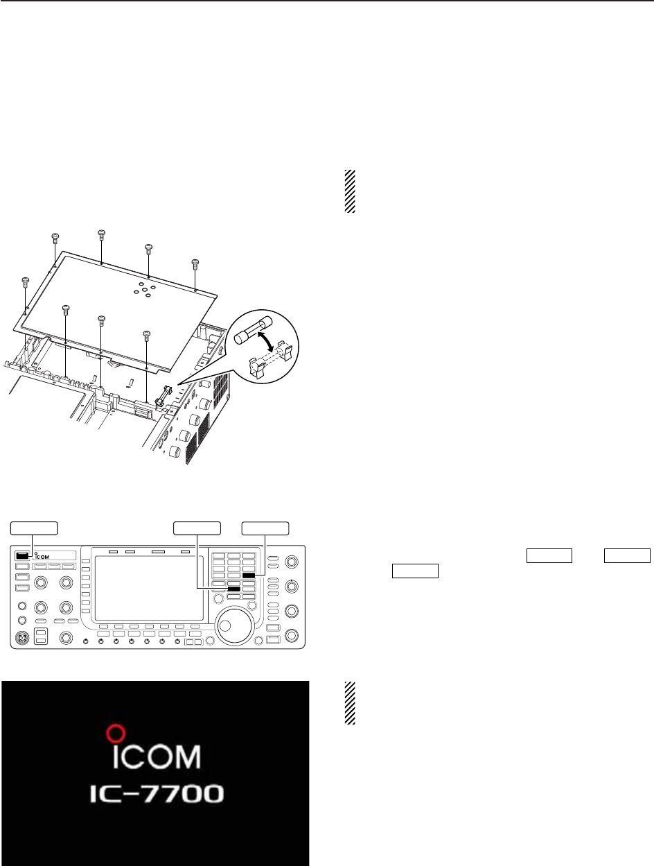
13-7
■Fuse replacement
When no external DC output is available from [EXT
DC] and ACC connectors, the internal fuse may be
open. Replace the fuse in this case.
WARNING: DISCONNECT the AC power cable
from the AC outlet before removing the transceiver’s
cover.
qRemove the bottom cover as shown left.
wRemove the 8 screws from the shield cover of the
transceiver’s bottom side.
eReplace the open fuse with a new, properly rated
one (FGB 2 A) as shown at left.
rReturn the inside cover and bottom cover and
screws to the original position.
■Resetting the CPU
qTurn the main power switch on the rear panel ON.
• Make sure the transceiver power is still OFF.
wWhile pushing and holding and ,
push to turn power ON.
• The internal CPU is reset.
• The CPU start-up takes approx. 5 sec.
• The transceiver displays its initial VFO frequencies
when resetting is complete.
eCorrect the set mode settings after resetting, if de-
sired.
NOTE: Resetting CLEARS all programmed con-
tents in memory channels and returns programmed
values in set mode to default values.
POWER
MW
F-INPENT
MW F-IMP ENT
POWER
13
MAINTENANCE
ALL CLEAR
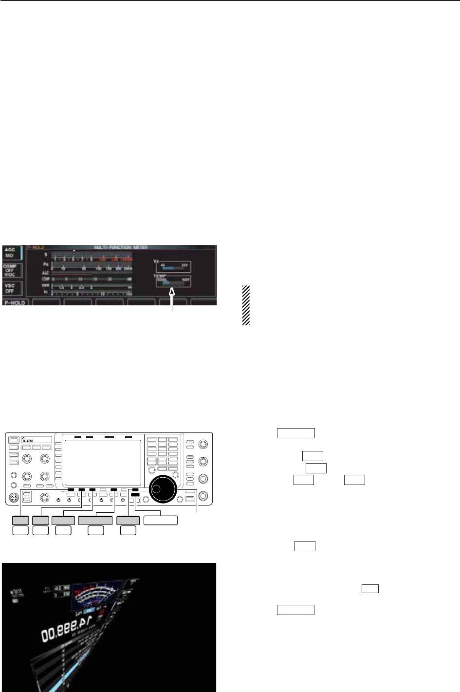
13-8
■About protection indications
The IC-7700 has a 2-step protection function to protect
the final power amplifiers.
The protector monitors the power amplifier tempera-
ture and activates when the temperature becomes ex-
tremely high.
• Power down transmission
Reduces the transmit output power to 100 W.
“LMT” appears beside the transmit indicator during
transmit.
• Transmission inhibit
Deactivates the transmitter.
The transmit indicator is displayed in gray during
transmit.
When the protector is activated, wait until the power
amplifier cools down using the transceiver in stand-
by or receive condition.
NOTE: DO NOT turn the transceiver power OFF
when the protector is ON. If you do, the cooling fan
will not function and it will take longer to cool the
transceiver.
The power amplifier temperature can be monitored in
the multi-function meter, TEMP gauge.
■Screen saver function
The IC-7700 has a screen saver function to protect the
LCD from the “burn-in” effect.
qPush several times to close a multi-func-
tion screen, if necessary.
wPush [SET] to select set mode menu screen.
ePush [DISP] to enter display set mode.
rPush [Y] or [Z] several times to select
the “Screen Saver Function” item.
tRotate the main dial to select the desired time pe-
riod for the screen saver activation from 15, 30,
60 min. and OFF.
• Deactivate the screen saver with “OFF” selection.
yPush [Z] to select the “Screen Saver Type”
item.
uRotate the main dial to select the screen saver type
from “Bound,” “Rotation” and “Twist.”
• Push and hold [PREVIEW] to display the indica-
tion for your reference.
iPush twice to exit set mode.
EXIT/SET
F-5
F-2
F-2F-1
F-3
F-7
EXIT/SET
Check the temperature
Main dial
F-2 F-3F-1
DISP
F-5
PREVIEW EXIT/SET
F-7
SET
∫ √
13 MAINTENANCE

14-1
CONTROL COMMAND Section 14
■Remote jack (CI-V) information ……………………………………… 14-2
DCI-V connection example ………………………………………… 14-2
DData format ………………………………………………………… 14-2
DCommand table …………………………………………………… 14-3
DTo send/read memory contents …………………………………… 14-9
DBand stacking register …………………………………………… 14-9
DCodes for memory keyer contents ……………………………… 14-9
DCodes for memory name, opening message
and CLOCK2 name contents ……………………………………… 14-9
DOffset frequency setting ………………………………………… 14-10
DRepeater tone/tone squelch frequency setting ………………… 14-10
DSSB transmission passband width setting …………………… 14-10
DColor setting ……………………………………………………… 14-10
DBandscope edge frequency setting …………………………… 14-10
DData mode with filter width setting ……………………………… 14-10
DAntenna memory setting ………………………………………… 14-10
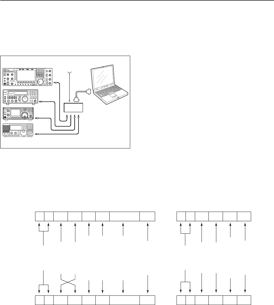
14-2
■Remote jack (CI-V) information
D
CI-V connection example
The transceiver can be connected through an optional
CT-17 CI-V LEVEL CONVERTER to a PC equipped with an
RS-232C port. The Icom Communications Interface-V
(CI-V) controls the transceiver.
Up to 4 Icom CI-V transceivers or receivers can be
connected to a PC equipped with an RS-232C port.
See p. 12-17 for setting the CI-V condition using set
mode.
D
Data format
The CI-V system can be operated using the following
data formats. Data formats differ according to com-
mand numbers. A data area or sub command is added
for some commands.
Controller to IC-7700
FE FE 74 E0 Cn Sc Data area FD
Preamble
code (fixed)
Transceiver’s
default address
Controller’s
default address
Command number
(see the command table)
Sub command number
(see command table)
BCD code data for
frequency or memory
number entry
End of message
code (fixed)
OK message to controller
FE FE E0 74 FB FD
FE FE E0 74 FA FD
Preamble
code (fixed)
Controller’s
default address
Transceiver’s
default address
OK code
(fixed)
End of message
code (fixed)
NG message to controller
NG code
(fixed)
IC-7700 to controller
qwert y u
FE FE E0 74 Cn Sc Data area FD
qwert y u
personal
computer
ct- 17
IC-7700 9–15 V DC
mini-plug cable
14 CONTROL COMMAND

14-3
D
Command table
14
CONTROL COMMAND
00 — Send frequency data
01 Same as Send mode data
command 06
02 — Read band edge frequencies
03 — Read operating frequency
04 — Read operating mode
05 — Set operating frequency
06 00 Select LSB
01 Select USB
02 Select AM
03 Select CW
04 Select RTTY
05 Select FM
07 Select CW-R
08 Select RTTY-R
12 Select PSK
13 Select PSK-R
07 — Select VFO mode
00 Select VFO-A
01 Select VFO-B
A0 Equalize VFO-A and VFO-B
B0 Exchange VFO-A and VFO-B
08 — Select memory mode
0001–0101* Select memory channel
*P1=0100, P2=0101
09 — Memory write
0A — Memory to VFO
0B — Memory clear
0E 00 Scan stop
01 Programmed/memory scan start
02 Programmed scan start
03 ∂F scan start
12 Fine programmed scan start
13 Fine ∂F scan start
22 Memory scan start
23 Select memory scan start
A1–A7 Set ∂F scan span (A1=±5 kHz;
A2=±10 kHz; A3=±20 kHz;
A4=±50 kHz; A5=±100 kHz;
A6=±500 kHz; A7=±1 MHz)
B0 Set as non-select channel
B1 Set as select channel
(1=★1; 2=★2; 3=★3; when no
data command is specified, the
previously set number or “★1” is
selected)
B2 Set the number for select memory
scan (0=ALL; 1=★1; 2=★2; 3=★3)
D0 Set scan resume OFF
D3 Set scan resume ON
0F 00 Turn the split function OFF
01 Turn the split function ON
10 00 Select 10 Hz (1 Hz) tuning step
01 Select 100 Hz tuning step
02 Select 1 kHz tuning step
03 Select 5 kHz tuning step
04 Select 9 kHz tuning step
05 Select 10 kHz tuning step
06 Select 12.5 kHz tuning step
07 Select 20 kHz tuning step
08 Select 25 kHz tuning step
11 — Select/read attenuator
(0=OFF; 1=6 dB; 2=12 dB;
3=18 dB)
12 00 + RX ANT Select/read ANT1 selection
(00=RX ANT OFF;
01=RX ANT ON)
01 + RX ANT Select/read ANT2 selection
(00=RX ANT OFF;
01=RX ANT ON)
02 + RX ANT Select/read ANT3 selection
(00=RX ANT OFF;
01=RX ANT ON)
03 + RX ANT Select/read ANT4 selection
(00=RX ANT OFF;
01=RX ANT ON)
13 00 Announce with voice synthesizer
01 (00=all data; 01=frequency and
02 S-meter level; 02=receive mode)
14 01 + Level data [AF] level setting
(0=max. CCW to 255=max. CW)
02 + Level data [RF] level setting
(0=max. CCW to 255=11 o’clock)
03 + Level data [SQL] level setting
(0=11 o’clock to 255=max. CW)
05 + Level data [APF] level setting
(0=Pitch–550 Hz, 128=Pitch,
255=Pitch+550 Hz; 10 Hz steps)
06 + Level data [NR] level setting
(0=min. to 255=max.)
07 + Level data Inside [TWIN PBT] setting or IF
shift setting (0=max. CCW,
128=center, 255=max. CW)
08 + Level data Outside [TWIN PBT] setting
(0=max. CCW, 128=center,
255=max. CW)
09 + Level data [CW PITCH] setting
(0=300 Hz, 128=600 Hz,
255=900 Hz; 5 Hz steps)
0A + Level data [RF POWER] setting (0=max.
CCW to 255=max. CW)
0B + Level data [MIC] setting (0=max. CCW to
255=max. CW)
0C + Level data [KEY SPEED] setting (0=max.
CCW to 255=max. CW)
0D + Level data [NOTCH] setting
(0=low freq. to 255=high freq.)
0E + Level data [COMP] setting
(0=max. CCW to 255=max. CW)
0F + Level data [DELAY] setting
(0=max. CCW to 255=max. CW)
11 + Level data [AGC] control setting
(0=max. CCW to 255=max. CW)
12 + Level data [NB] control setting
(0=max. CCW to 255=max. CW)
13 + Level data [DIGI-SEL] setting
(0=max. CCW to 255=max. CW)
14 + Level data [DRIVE] setting
(0=max. CCW to 255=max. CW)
15 + Level data [MONI GAIN] setting (0=max.
CCW to 255=max. CW)
16 + Level data [VOX GAIN] setting (0=max.
CCW to 255=max. CW)
17 + Level data [ANTI VOX] setting
(0=max. CCW to 255=max. CW)
Command Sub command Description Command Sub command Description

14-4
D
Command table (continued)
14 CONTROL COMMAND
14 18 + Level data [CONTRAST] setting (0=max.
CCW to 255=max. CW)
19 + Level data [BRIGHT] setting
(0=max. CCW to 255=max. CW)
15 01 Read squelch condition
02 Read S-meter level
11 Read RF power meter
12 Read SWR meter
13 Read ALC meter
14 Read COMP meter
15 Read VDmeter
16 Read IDmeter
16 02 Send/read Preamp setting
(0=OFF; 1=preamp 1;
2=preamp 2)
12 Send/read AGC selection
(0=OFF; 1=Slow; 2=Mid; 3=Fast)
22 Send/read noise blanker setting
(0=OFF; 1=ON)
32 Send/read Audio peak filter set-
ting for CW mode
(APF type=SHARP: 0=OFF;
1=320 Hz; 2=160 Hz; 3=80 Hz,
APF type=SOFT: 0=OFF;
1=WIDE; 2=MID; 3=NAR)
40 Send/read noise reduction setting
(0=OFF; 1=ON)
41 Send/read auto notch setting
(0=OFF; 1=ON)
42 Send/read repeater tone setting
(0=OFF; 1=ON)
43 Send/read tone squelch setting
(0=OFF; 1=ON)
44 Send/read speech compressor
setting (0=OFF; 1=ON)
45 Send/read monitor setting
(0=OFF; 1=ON)
46 Send/read VOX function setting
(0=OFF; 1=ON)
47 Send/read Break-in function set-
ting (0=OFF; 1=semi break-in;
2=full break-in)
48 Send/read manual notch setting
(0=OFF; 1=ON)
4C Send/read VSC setting
(0=OFF; 1=ON)
4D Send/read Manual AGC setting
(0=OFF; 1=ON)
4E Send/read DIGI-SEL setting
(0=OFF; 1=ON)
4F Send/read twin peak filter setting
(0=OFF; 1=ON)
50 Send/read dial lock function set-
ting (0=OFF; 1=ON)
53 Send/read RX antenna connector
setting (0=OFF; 1=ON)
19 00 Read the transceiver ID
1A 00 Send/read memory contents (see
p. 14-9 for details)
01 Send/read band stacking register
contents (see p. 14-9 for details)
02 Send/read memory keyer con-
tents (see p. 14-9 for details)
1A 03 Send/read the selected filter width
(SSB, CW, PSK: 0=50 Hz to
40=3600 Hz; RTTY: 0=50 Hz to
31=2700 Hz; AM: 0=200 Hz to
49=10 kHz)
04 Send/read the selected AGC time
constant (0=OFF, 1=0.1/0.3 sec.
to 13=6.0/8.0 sec.)
050001 Send/read SSB RX HPF/LPF
(HPF: 0=Through, 1=100 to
20=2000, LPF: 5=500 to
24=2400, 25=Through)
050002 Send/read SSB RX Tone (Bass)
level (0 =–5 to 10=+5)
050003 Send/read SSB RX Tone (Treble)
level (0=–5 to 10=+5)
050004 Send/read AM RX HPF/LPF
(HPF: 0=Through, 1=100 to
20=2000, LPF: 5=500 to
24=2400, 25=Through)
050005 Send/read AM RX Tone (Bass)
level (0 =–5 to 10=+5)
050006 Send/read AM RX Tone (Treble)
level (0=–5 to 10=+5)
050007 Send/read FM RX HPF/LPF
(HPF: 0=Through, 1=100 to
20=2000, LPF: 5=500 to
24=2400, 25=Through)
050008 Send/read FM RX Tone (Bass)
level (0 =–5 to 10=+5)
050009 Send/read FM RX Tone (Treble)
level (0=–5 to 10=+5)
050010 Send/read CW RX HPF/LPF
(HPF: 0=Through, 1=100 to
20=2000, LPF: 5=500 to
24=2400, 25=Through)
050011 Send/read RTTY RX HPF/LPF
(HPF: 0=Through, 1=100 to
20=2000, LPF: 5=500 to
24=2400, 25=Through)
050012 Send/read PSK RX HPF/LPF
(HPF: 0=Through, 1=100 to
20=2000, LPF: 5=500 to
24=2400, 25=Through)
050013 Send/read SSB TX Tone (Bass)
level (0 =–5 to 10=+5)
050014 Send/read SSB TX Tone (Treble)
level (0=–5 to 10=+5)
050015 Send/read AM TX Tone (Bass)
level (0 =–5 to 10=+5)
050016 Send/read AM TX Tone (Treble)
level (0=–5 to 10=+5)
050017 Send/read FM TX Tone (Bass)
level (0 =–5 to 10=+5)
050018 Send/read FM TX Tone (Treble)
level (0=–5 to 10=+5)
050019 Send/read SSB TX bandwidth for
wide (see p. 14-10 for details)
050020 Send/read SSB TX bandwidth for
mid. (see p. 14-10 for details)
050021 Send/read SSB TX bandwidth for
narrow (see p. 14-10 for details)
050022 Send/read speech level
(0=0% to 255=100%)
Command Sub command Description Command Sub command Description

14-5
D
Command table (continued)
14
CONTROL COMMAND
1A 050023 Send/read CW side tone gain
(0=min. to 255=max.)
050024 Send/read CW side tone gain limit
(0=OFF, 1=ON)
050025 Send/read beep gain
(0=min. to 255=max.)
050026 Send/read beep gain limit
(0=OFF, 1=ON)
050027 Send/read headphones output
ratio (0=0.60 to 255=1.40)
050028 Send/read AF output level to ACC
(0=0% to 255=100%)
050029 Send/read S/P DIF output level
(0=0% to 255=100%)
050030 Send/read MOD output level to
ACC (0=0% to 255=100%)
050031 Send/read S/P DIF MOD output
level (0=0% to 255=100%)
050032 Send/read MOD input connector
during DATA OFF (0=MIC;
1=ACC; 2=MIC/ACC; 3=S/P DIF)
050033 Send/read MOD input connector
during DATA1
(0=MIC; 1=ACC; 2=MIC/ACC;
3=S/P DIF)
050034 Send/read MOD input connector
during DATA2
(0=MIC; 1=ACC; 2=MIC/ACC;
3=S/P DIF)
050035 Send/read MOD input connector
during DATA3
(0=MIC; 1=ACC; 2=MIC/ACC;
3=S/P DIF)
050036 Send/read relay type selection
(0=Lead, 1=MOS-FET)
050037 Send/read external meter output
selection
(0=Auto, 1=S, 2=Po, 3=SWR,
4=ALC, 5=COMP, 6=VD, 7=ID)
050038 Send/read external meter output
level (0=0% to 255=100%)
050039 Send/read reference signal in/out
setting (0=OFF, 1=IN, 2=OUT)
050040 Send/read reference signal fre-
quency setting
(0=0% to 255=100%)
050041 Send/read LCD unit backlight
brightness (0=0% to 255=100%)
050042 Send/read switch indicator bright-
ness (0=0% to 255=100%)
050043 Send/read screen image type
(0=A, 1=B)
050044 Send/read frequency readout font
(0=Basic (1), 1=Basic (2), 2=Italic,
3=Round, 4=Slim)
050045 Send/read meter response setting
(0=SLOW, 1=MID, 2=FAST)
050046 Send/read meter type
(0=Standard, 1=Edgewise, 2=Bar)
050047 Send/read meter type during wide
screen or mini scope indication
(0=Edgewise, 1=Bar)
050048 Send/read peak hold set for Bar
meter (0=OFF, 1=ON)
1A 050049 Send/read memory name indica-
tion setting (0=OFF, 1=ON)
050050 Send/read audio peak filter width
pop-up indication setting
(0=OFF, 1=ON)
050051 Send/read manual notch width
pop-up indication setting
(0=OFF, 1=ON)
050052 Send/read screen saver set
(0=OFF, 1=15 min., 2=30 min.,
3=60 min.)
050053 Set/read screen saver type
(0=Bound, 1=Rotation, 2=Twist)
050054 Send/read output signal setting for
external display (0=OFF, 1=ON)
050055 Send/read synchronous pulse
level setting (0=L, 1=H)
050056 Send/read opening message indi-
cation (0=OFF, 1=ON)
050057 Send/read opening message con-
tents (see p. 14-9 for details)
050058 Send/read date
(20000101=1st Jan. 2000 to
20991231=31st Dec. 2099)
050059 Send/read time
(0000=00:00 to 2359=23:59)
050060 Send/read CLOCK2 function
(0=OFF, 1=ON)
050061 Send/read offset time for CLOCK2
(240001=–24:00 to
240000=+24:00)
050062 Send/read CLOCK2 name
(up to 3-character; see p. 14-9)
050063 Send/read calibration marker
(0=OFF, 1=ON)
050064 Send/read confirmation beep
(0=OFF, 1=ON)
050065 Send/read band edge beep
(0=OFF, 1=ON)
050066 Send/read beep audio frequency
(50=500 Hz to 200=2000 Hz)
050067 Send/read quick split set
(0=OFF, 1=ON)
050068 Send/read FM split offset –9.999
to +9.999 MHz for HF
(see p. 14-10 for details)
050069 Send/read FM split offset –9.999
to +9.999 MHz for 50 MHz
(see p. 14-10 for details)
050070 Send/read split lock set
(0=OFF, 1=ON)
050071 Send/read tuner auto start set
(0=OFF, 1=ON)
050072 Send/read PTT tune set
(0=OFF, 1=ON)
050073 Send/read transverter set
(0=OFF, 1=ON)
050074 Send/read transverter offset
(see p. 14-10 for details)
050075 Send/read RTTY mark frequency
(0=1275 Hz, 1=1615 Hz,
2=2125 Hz)
050076 Send/read RTTY shift width
(0=170 Hz, 1=200 Hz, 2=425 Hz)
Command Sub command Description Command Sub command Description

14-6
D
Command table (continued)
14 CONTROL COMMAND
1A 050077 Send/read RTTY keying polarity
(0=Normal, 1=Reverse)
050078 Send/read PSK tone frequency
(0=1000 Hz, 1=1500 Hz,
2=2000 Hz)
050079 Send/read speech language
(0=English, 1=Japanese)
050080 Send/read speech speed
(0=Slow, 1=Fast)
050081 Send/read S-level speech
(0=OFF, 1=ON)
050082 Send/read speech with a mode
switch operation (0=OFF, 1=ON)
050083 Send/read memo pad numbers
(0=5 ch, 1=10 ch)
050084 Send/read main dial auto TS
(0=OFF, 1=Low, 2=High)
050085 Send/read mic. up/down speed
(0=Low, 1=High)
050086 Send/read quick RIT/∂TX clear
function (0=OFF, 1=ON)
050087 Send/read SSB notch operation
(0=Auto, 1=Manual,
2=Auto/Manual)
050088 Send/read AM notch operation
(0=Auto, 1=Manual,
2=Auto/Manual)
050089 Send/read DIGI-SEL control func-
tion (0=DIGI-SEL, 1=APF)
050090 Send/read SSB/CW synchronous
tuning function (0=OFF, 1=ON)
050091 Send/read CW normal side set
(0=LSB, 1=USB)
050192 Set/read APF type
(0=SHARP, 1=SOFT)
050093 Send/read external keypad set
for voice memory (0=OFF, 1=ON)
050094 Send/read external keypad set
for keyer memory (0=OFF, 1=ON)
050095 Send/read CI-V transceive set
(0=OFF, 1=ON)
050096 Send/read RS-232C function
(0=CI-V, 1=Decode)
050097 Send/read RS-232C decode
Baud rate (0=300, 1=1200,
2=4800, 3=9600, 4=19200)
050098 Send/read keyboard type
(00=English, 01=Japanese,
02=United Kingdom, 03=French,
04=French (Canadian),
05=German, 06=Portuguese,
07=Portuguese (Brazilian),
08=Spanish, 09=Spanish (Latin
American), 10=Italian)
050099 Send/read keyboard repeat delay
(10=100 msec. to
100=1000 msec.)
050100 Send/read keyboard repeat rate
(0=2.0 cps to 31=30.0 cps)
050101 Send/read IP address set
(0000000000000001=0.0.0.1 to
0255025502550254=255.255.25
5.254)
1A 050102 Send/read subnet mask
(1=128.0.0.0 to
30=255.255.255.252)
050103 Send/read scope indication during
TX (0=OFF, 1=ON)
050104 Send/read scope max. hold
(0=OFF, 1=ON)
050105 Send/read scope center frequen-
cy set (0=Filter center, 1=Carrier
point center, 2=Carrier point cen-
ter (Abs. Freq.))
050106 Send/read waveform color for
receiving signal
(see p. 14-10 for details)
050107 Send/read waveform color for
max. hold
(see p. 14-10 for details)
050108 Send/read scope sweep speed
for ±2.5 kHz span
(0=Slow, 1=Mid., 2=Fast)
050109 Send/read scope sweep speed
for ±5 kHz span
(0=Slow, 1=Mid., 2=Fast)
050110 Send/read scope sweep speed
for ±10 kHz span
(0=Slow, 1=Mid., 2=Fast)
050111 Send/read scope sweep speed
for ±25 kHz span
(0=Slow, 1=Mid., 2=Fast)
050112 Send/read scope sweep speed
for ±50 kHz span
(0=Slow, 1=Mid., 2=Fast)
050113 Send/read scope sweep speed
for ±100 kHz span
(0=Slow, 1=Mid., 2=Fast)
050114 Send/read scope sweep speed
for ±250 kHz span
(0=Slow, 1=Mid., 2=Fast)
050115 Send/read scope edge frequen-
cies for 0.03 to 1.60 MHz band
(see p. 14-10 for details)
050116 Send/read scope edge frequen-
cies for 1.60 to 2.00 MHz band
(see p. 14-10 for details)
050117 Send/read scope edge frequen-
cies for 2.00 to 6.00 MHz band
(see p. 14-10 for details)
050118 Send/read scope edge frequen-
cies for 6.00 to 8.00 MHz band
(see p. 14-10 for details)
050119 Send/read scope edge frequen-
cies for 8.00 to 11.00 MHz band
(see p. 14-10 for details)
050120 Send/read scope edge frequen-
cies for 11.00 to 15.00 MHz band
(see p. 14-10 for details)
050121 Send/read scope edge frequen-
cies for 15.00 to 20.00 MHz band
(see p. 14-10 for details)
050122 Send/read scope edge frequen-
cies for 20.00 to 22.00 MHz band
(see p. 14-10 for details)
050123 Send/read scope edge frequen-
cies for 22.00 to 26.00 MHz band
(see p. 14-10 for details)
Command Sub command Description Command Sub command Description

14-7
D
Command table (continued)
14
CONTROL COMMAND
1A 050124 Send/read scope edge frequen-
cies for 26.00 to 30.00 MHz band
(see p. 14-10 for details)
050125 Send/read scope edge frequen-
cies for 30.00 to 45.00 MHz band
(see p. 14-10 for details)
050126 Send/read scope edge frequen-
cies for 45.00 to 60.00 MHz band
(see p. 14-10 for details)
050127 Send/read auto voice monitor set
(0=OFF, 1=ON)
050128 Send/read voice memory short
play time (3=3 sec. to 10=10 sec.)
050129 Send/read voice memory normal
record time
(5= 5 sec. to 15=15 sec.)
050130 Send/read contest number style
(0=Normal, 1=190AANO,
2=190AANT, 3=90ANO,
4=90ANT)
050131 Send/read count up trigger chan-
nel (1=M1, 2=M2, 3=M3, 4=M4)
050132 Send/read present number
(1–9999)
050133 Send/read CW keyer repeat time
(1=1 sec. to 60=60 sec.)
050134 Send/read CW keyer dot/dash
ratio (28=1:1:2.8 to 45=1:1:4.5)
050135 Send/read rise time
(0=2 msec., 1=4 msec.,
2=6 msec., 3=8 msec.)
050136 Send/read paddle polarity
(0=Normal, 1=Reverse)
050137 Send/read keyer type (0=Straight,
1=Bug-key, 2=ELEC-Key)
050138 Send/read mic. up/down keyer set
(0=OFF, 1=ON)
050139 Send/read FFT scope averaging
set for RTTY decoder
(0=OFF, 1=2, 2=3, 3=4)
050140 Send/read FFT scope waveform
color set for RTTY decoder
(see p. 14-10 for details)
050141 Send/read RTTY decode USOS
(0=OFF, 1=ON)
050142 Send/read RTTY decode new line
code
(0=CR,LF,CR+LF, 1=CR+LF)
050143 Send/read RTTY diddle (0=OFF,
1=Blank, 2=LTRS (Letter code))
050144 Send/read RTTY TX USOS
(0=OFF, 1=ON)
050145 Send/read RTTY auto CR+LF by
TX (0=OFF, 1=ON)
050146 Send/read RTTY time stamp set
(0=OFF, 1=ON)
050147 Send/read clock selection for time
stamp (0=Local time, 1=CLOCK2)
050148 Send/read frequency stamp
(0=OFF, 1=ON)
050149 Send/read received text font color
(see p. 14-10 for details)
050150 Send/read transmitted text font
color (see p. 14-10 for details)
1A 050151 Send/read time stamp text font
color (see p. 14-10 for details)
050152 Send/read text font color in TX
buffer (see p. 14-10 for details)
050153 Send/read FFT scope averaging
set for PSK decoder
(0=OFF, 1=2, 2=3, 3=4)
050154 Send/read FFT scope waveform
color set for PSK decoder
(see p. 14-10 for details)
050155 Send/read PSK AFC function tun-
ing range (0=±8 Hz, 1=±15 Hz)
050156 Send/read PSK time stamp set
(0=OFF, 1=ON)
050157 Send/read clock selection for time
stamp (0=Local time, 1=CLOCK2)
050158 Send/read frequency stamp
(0=OFF, 1=ON)
050159 Send/read received text font color
(see p. 14-10 for details)
050160 Send/read transmitted text font
color (see p. 14-10 for details)
050161 Send/read time stamp text font
color (see p. 14-10 for details)
050162 Send/read text font color in TX
buffer (see p. 14-10 for details)
050163 Send/read scan speed
(0=Low, 1=High)
050164 Send/read scan resume
(0=OFF, 1=ON)
050165 Send/read antenna selection for
0.03 to 1.60 MHz band
(see p. 14-10 for details)
050166 Send/read antenna selection for
1.60 to 2.00 MHz band
(see p. 14-10 for details)
050167 Send/read antenna selection for
2.00 to 6.00 MHz band
(see p. 14-10 for details)
050168 Send/read antenna selection for
6.00 to 8.00 MHz band
(see p. 14-10 for details)
050169 Send/read antenna selection for
8.00 to 11.00 MHz band
(see p. 14-10 for details)
050170 Send/read antenna selection for
11.00 to 15.00 MHz band
(see p. 14-10 for details)
050171 Send/read antenna selection for
15.00 to 20.00 MHz band
(see p. 14-10 for details)
050172 Send/read antenna selection for
20.00 to 22.00 MHz band
(see p. 14-10 for details)
050173 Send/read antenna selection for
22.00 to 26.00 MHz band
(see p. 14-10 for details)
050174 Send/read antenna selection for
26.00 to 30.00 MHz band
(see p. 14-10 for details)
050175 Send/read antenna selection for
30.00 to 45.00 MHz band
(see p. 14-10 for details)
Command Sub command Description Command Sub command Description

D
Command table (continued)
14-8
14 CONTROL COMMAND
1A 050176 Send/read antenna selection for
45.00 to 60.00 MHz band
(see p. 14-10 for details)
050177 Send/read antenna temporary
memory set (0=OFF, 1=ON)
050178 Send/read antenna selection
(0=OFF, 1=Manual, 2=Auto)
050179 Send/read usage for ANT2
(0=OFF, 1=TX/RX)
050180 Send/read usage for ANT3
(0=OFF, 1=TX/RX)
050181 Send/read usage for ANT4
(0=OFF, 1=TX/RX, 2= RX)
050182 Send/read VOX delay (0=0.0 sec.
to 20=2.0 sec.)
050183 Send/read VOX voice delay
(0=OFF, 1=Short, 2=Mid.,
3=Long)
050184 Send/read NB depth (0=1 to 9=10)
050185 Send/read NB width
(0=0 to 255=255)
06 Send/read DATA mode with filter
set (see p. 14-10 for detail)
07 Send/read SSB transmit band-
width (0=WIDE, 1=MID, 2=NAR)
08 Send/read DSP filter shape
(0= Sharp, 1= Soft)
09 Send/read roofing filter set
(0=3 kHz, 1=6 kHz, 2=15 kHz)
0A Send/read manual notch width
(0=Wide, 1=Mid., 2=Nar.)
1B 00 Send/read repeater tone frequen-
cy (see p. 14-10 for details)
01 Set/read TSQL tone frequency
(see p. 14-10 for details)
1C 00 Send/read the transceiver’s condi-
tion (0=Rx; 1=Tx)
01 Send/read antenna tuner condi-
tion
(0=OFF, 1=ON, 2=Start tuning or
while tuning)
Command Sub command Description

14-9
14
CONTROL COMMAND
D
To send/read memory contents
When sending or reading memory contents, additional
codes must be added to append the memory channel
as follows.
➥Additional code: 0000–0101 (0100=P1, 0101=P2)
D
Band stacking register
To send or read the desired band stacking register’s
contents, combined codes of the frequency band and
register codes as follows are used.
For example, when sending/reading the oldest con-
tents in the 21 MHz band, the code “0703” is used.
• Frequency band code
• Register code
D
Codes for memory keyer contents
To send or read the desired memory keyer contents,
the channel and character codes as follows are used.
• Channel code
• Character’s code
D
Codes for memory name, opening
message and CLOCK2 name contents
To send or read the desired memory name settings,
the character codes, instructed codes for memory
keyer contents as above, and follows are used.
•Character’s code— Alphabetical characters
•Character’s code— Symbols
Character ASCII code Character ASCII code
a–z 61–7A — —
Code Frequency band Frequency range (unit: MHz)
01 1.8 1.800000– 1.999999
02 3.5 3.400000– 4.099999
03 7 6.900000– 7.499999
04 10 9.900000–10.499999
05 14 13.900000–14.499999
06 18 17.900000–18.499999
07 21 20.900000–21.499999
08 24 24.400000–25.099999
09 28 28.000000–29.999999
10 50 50.000000–54.000000
12 GENE Other than above
Code Registered number
01 1 (latest)
02 2
03 3 (oldest)
Character ASCII code Description
0–9 30–39 Numerals
A–Z 41–5A Alphabetical characters
space 20 Word space
/ 2F Symbol
? 3F Symbol
, 2C Symbol
. 2E Symbol
^ 5E e.g., to send BT, enter ^4254
✱2A Inserts contest number (can be
used for 1 channel only)
Code Channel number
01 M1
02 M2
03 M3
04 M4
Character ASCII code Character ASCII code
! 21#23
$24%25
&26¥5C
?3F ” 22
’27`60
+2B–2D
:3A;3B
=3D<3C
>3E ( 28
)29[5B
]5D{7B
}7D|7C
_5F–7E
@40
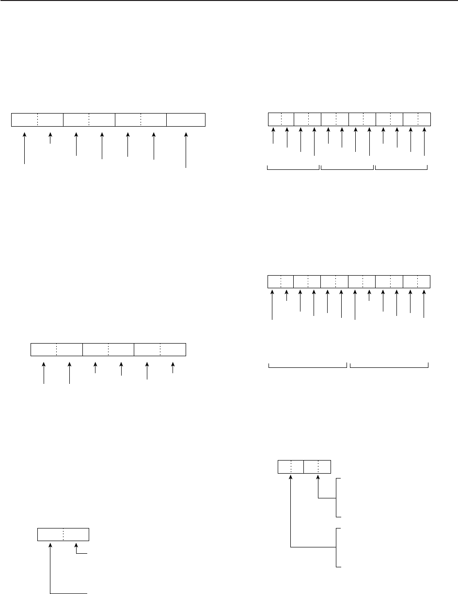
14-10
14 CONTROL COMMAND
D
Offset frequency setting
The following data sequence is used when sending or
reading the offset frequency setting.
D
Repeater tone/tone squelch frequency
setting
The following data sequence is used when sending or
reading the tone frequency setting.
D
SSB transmission passband width
setting
The following data sequence is used when sending or
reading the SSB transmission passband width setting.
D
Color setting
The following data sequence is used when sending or
reading the color setting.
D
Bandscope edge frequency setting
The following data sequence is used when sending or
reading the bandscope edge frequency setting.
D
Data mode with filter width setting
The following data sequence is used when sending or
reading the data mode with filter width setting.
D
Antenna memory setting
The following codes are used when sending or read-
ing the antenna memory setting.
0=ANT1, 1=ANT2, 2=ANT3, 3=ANT4,
4*=TX: ANT1, RX: ANT4, 5*=TX: ANT2, RX: ANT4,
6*=TX: ANT3, RX: ANT4
*RX should be selected for ANT4
q
XXXX
w
00=Data mode OFF
01=FIL1
02=FIL2
03=FIL3
00=Data mode OFF
01=Data mode 1 (D1)
02=Data mode 2 (D2)
03=Data mode 3 (D3)
1 kHz: 0–9
100 Hz: 0 (fixed)
100 kHz: 0–9
10 kHz: 0–9
10 MHz: 0–6
1 MHz: 0–9
1 kHz: 0–9
100 Hz: 0 (fixed)
100 kHz: 0–9
10 kHz: 0–9
10 MHz: 0–6
1 MHz: 0–9
q
XXXXXXXXXXXX
werty
Lower edge Higher edge
1000
100
10
1
q
0XXX0XXX0XXX
werty
1000
100
10
1
1000
100
10
1
R (Red) G (Green) B (Blue)
Using 0000–0255 for each color element.
XX
Higher edge: 0=2500 Hz
1=2700 Hz
2=2800 Hz
3=2900 Hz
Lower edge: 0=100 Hz
1=200 Hz
2=300 Hz
3=500 Hz
100Hz digit: 0–2
10 Hz digit: 0–9
1 Hz digit: 0–9
0.1 Hz digit: 0–9
Fixed digit: 0*
Fixed digit: 0*
q*
00XXX
we
X
*Not necessary when setting a frequency.
1 kHz digit: 0–9
100 Hz digit: 0 (fixed)
100 kHz digit: 0–9
10 kHz digit: 0–9
10 MHz digit: 0–9†
1 MHz digit: 0–4
Direction:
00=+ direction
01=– direction
q
0XXXXXX
we
0
r*
*No need to enter for transverter offset frequency setting.
†Transverter offset only; Fix to ‘0’ for split offset setting.

15-1
SPECIFICATIONS AND OPTIONS Section 15
■Specifications ………………………………………………………… 15-2
DGeneral ……………………………………………………………… 15-2
DTransmitter ………………………………………………………… 15-2
DReceiver …………………………………………………………… 15-3
DAntenna tuner ……………………………………………………… 15-3
■Options ………………………………………………………………… 15-4

15-2
■Specifications
D
General
• Frequency coverage (unit: MHz) :
Receiver 0.030000–60.000000*1
Transmitter 1.800000–1.999999*2, 3.500000–3.999999*2,
5.330500*3, 5.346500*3, 5.366500*3, 5.371500*3,
5.403500*3, 7.000000–7.300000*2,
10.100000–10.150000*2, 14.000000–14.350000*2,
18.068000–18.168000*2, 21.000000–21.450000*2,
24.890000–24.990000*2, 28.000000–29.700000*2,
50.000000–54.000000*2
*1Some frequency ranges are not guaranteed.
*2Depending on versions. *3USA version only.
• Operating mode : USB, LSB, CW, RTTY, PSK31, AM, FM
• Number of memory channels : 101 (99 regular, 2 scan edges)
• Antenna connector : SO-239×4 (antenna impedance: 50 )
• Operating temperature range : 0˚C to +50˚C; +32˚F to +122˚F
• Frequency stability : Less than ±0.05 ppm (approx. 5 min. after from turn
the main power, [I/O], ON, 0–50˚C; 32–122˚F)
• Frequency resolution : 1Hz
• Power supply requirement : 85–265 V AC (universal input)
• Power consumption :
Receive Stand-by 200 VA typical
Max. audio 210 VA typical
Transmit at 200 W 800 VA
• Dimensions (projections not included) :425×149×437 mm; 1623⁄32×57⁄8×177⁄32 in
• Weight : Approx. 22.5 kg; 50 lb
• ACC 1 connectors : 8-pin DIN connector
• ACC 2 connectors : 7-pin DIN connector
• Display*:7-inch (diagonal) TFT color LCD (800×480)
• EXT-DISPLAY connector : D-sub 15S
• CI-V connector : 2-conductor 3.5 (d) mm (1⁄8w)
• RS-232C connector : D-sub 9-pin
• USB connector : USB (Universal Serial Bus)1.1/2.0×2
D
Transmitter
• Transmit output power :
SSB, CW, RTTY, PSK31, FM
5–200 W
AM 5–50 W
• Modulation system :
SSB P.S.N. modulation
AM Low power modulation
FM Phase modulation
• Spurious emission : More than 60 dB (HF bands)
More than 70 dB (50 MHz band)
• Carrier suppression : More than 63 dB
• Unwanted side-band suppression : More than 80 dB
•
∂
TX variable range : ±9.999 kHz
• Microphone connector : 8-pin connector (600 )
• ELEC-KEY connector : 3-conductor 6.35 (d) mm (1⁄4w)
• KEY connector : 3-conductor 6.35 (d) mm (1⁄4w)
• RELAY connector : Phono (RCA)
• ALC connector : Phono (RCA)
15 SPECIFICATIONS AND OPTIONS

15-3
D
Receiver
•Receive system : Double conversion superheterodyne system
•Intermediate frequencies :
1st 64.455 MHz
2nd 36 kHz
•Sensitivity (typical) :
SSB, CW, RTTY (BW=2.4 kHz, 10 dB S/N)
0.100000– 1.799999 MHz 0.5 μV (pre-amp 1 ON)
1.800000–29.990000 MHz 0.16 μV (pre-amp 1 ON)
50.000000–54.000000 MHz 0.13 μV (pre-amp 2 ON)
AM (BW=6 kHz, 10 dB S/N)
0.100000– 1.799999 MHz 6.3 μV (pre-amp 1 ON)
1.800000–29.990000 MHz 2 μV (pre-amp 1 ON)
50.000000–54.000000 MHz 1 μV (pre-amp 2 ON)
FM (BW=15 kHz, 12 dB SINAD)
28.000000–29.990000 MHz 0.5 μV (pre-amp 1 ON)
50.000000–54.000000 MHz 0.32 μV (pre-amp 2 ON)
• Internal Modulate Distortion (typical) :Dynamic range 105 dB
(at 14.100 MHz, 100 kHz separation, pre-amp OFF,
CW mode; BW=500 Hz)
• Selectivity :
SSB, RTTY (BW=2.4 kHz) More than 2.4 kHz/–3 dB
Less than 3.6 kHz/–60 dB
CW (BW=500 Hz) More than 500 Hz/–3 dB
Less than 700 Hz/–60 dB
AM (BW=6 kHz) More than 6.0 kHz/–3 dB
Less than 15.0 kHz/–60 dB
FM (BW=15 kHz) More than 12.0 kHz/–6 dB
Less than 20.0 kHz/–60 dB
• Spurious and image rejection ratio : More than 70 dB (except IF through on 50 MHz band)
• Squelch sensitivity (pre-amp OFF) :
SSB, CW, RTTY, PSK31 Less than 5.6 μV
FM Less than 1 μV
• RIT variable range : ±9.999 kHz
• Audio output power : More than 2.6 W at 10% distortion with an 8 load
• PHONES connector : 3-conductor 6.35 (d) mm (1⁄4w)
• EXT-SP connectors : 2-conductor 3.5 (d) mm (1⁄8w)/8
D
Antenna tuner
• Matching impedance range : 16.7 to 150 unbalanced
(HF bands; VSWR better than 3:1)
20 to 125 unbalanced
(50 MHz band; VSWR better than 2.5:1)
• Minimum operating input : 8W (HF bands)
15 W (50 MHz band)
• Tuning accuracy : VSWR 1.5:1 or less
• Insertion loss (after tuning) :Less than 1.0 dB
15
SPECIFICATIONS AND OPTIONS
*The LCD display may have cosmetic imperfections that appear as small or dark spots. This is not a malfunction
or defect, but a normal characteristic of LCD displays.
Spurious signals may be received near the following frequencies. These are made in the internal circuit and does
not indicate a transceiver malfunction.
• 0.15 MHz • 0.23 MHz 0.31 MHz • 10 MHz
Spurious waveforms may be displayed on the spectrum scope screen regardless of the transceiver’s condition
(Tx or Rx). They are made in the scope circuit. This does not indicate a transceiver malfunction.
All stated specifications are typical and subject to change without notice or obligation.
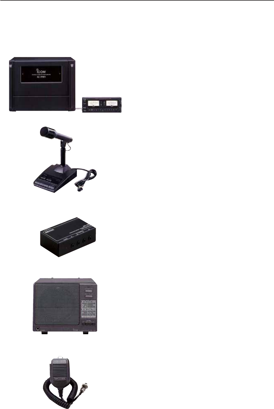
15-4
■Options
•IC-PW1/EURO HF
/50
MH
z
ALL BAND
1k
W LINEAR AMPLIFIER
Full-duty-cycle 1 kW linear amplifier including an auto-
matic antenna tuner. Has automatic tuning and band
selection capability when used with an Icom trans-
ceiver. Full break-in (QSK) operation. The
amplifier/power supply unit and the remote control unit
are separate.
•SM-20 DESKTOP MICROPHONE
Unidirectional, electret microphone for base station
operation. Includes [UP]/[DOWN] switches and a low
cut function.
•CT-17 CI-V LEVEL CONVERTER
For remote transceiver control using a PC. You can
change frequencies, operating mode, memory chan-
nels, etc. (software is not included)
•SP-20 EXTERNAL SPEAKER
4 audio filters; headphone jack; can connect to 2
transceivers.
• Input impedance : 8
• Max. input power : 5 W
•HM-36 HAND MICROPHONE
Hand microphone equipped with [UP]/[DOWN] switch-
es.
15 SPECIFICATIONS AND OPTIONS

16-1
UPDATING THE FIRMWARE Section 16
■General ………………………………………………………………… 16-2
■Caution ………………………………………………………………… 16-2
■Preparation …………………………………………………………… 16-3
DFirmware and firm utility …………………………………………… 16-3
DFile downloading …………………………………………………… 16-3
■Firmware update— USB-Memory …………………………………… 16-4
■Firmware update— PC ……………………………………………… 16-6
DConnections ………………………………………………………… 16-6
DIP address setting ………………………………………………… 16-7
DUpdating from the PC ……………………………………………… 16-8

16-2
■General
The IC-7700’s firmware can be updated if desired. By
updating the firmware, new function(s) can be added
and the improvement of performance parameters can
be made.
2 methods of firmware update are available: one uses
the USB-Memory, and the other uses a PC. You can
choose either methods according to your PC capabili-
ties.
• When only one PC connected to the Internet is avail-
able
➥Refer to ■Preparation (p. 16-3) and ■Firmware
update— USB-Memory (p. 16-4)
• When two or more PCs connected to the Internet are
available and they are connected to a LAN (Local
Area Network)
➥Refer to ■Preparation (p. 16-3) and either
■Firmware update— PC (p. 16-6) or
■Firmware update— USB-Memory (p. 16-4)
Ask your dealer or distributor about how to update the
firmware if you have no PC.
■Caution
RCAUTION!: NEVER turn the transceiver power OFF
while updating the firmware.
You can turn the transceiver power OFF only when the
transceiver displays that rebooting is required.
If you turn the transceiver power OFF, or if a power fail-
ure occurs during updating, the transceiver firmware
will be corrupted and you will have to send the trans-
ceiver back to the nearest Icom distributor for repair.
This type of repair is out of warranty even if the war-
ranty period is still valid.
Recommendation!
Backing up the settings and/or memory contents to the
USB-Memory before starting the firmware update is
recommended.
Settings and/or memory contents will be lost or re-
turned to default settings when the firmware update is
performed.
At least one available USB (2.0 or 1.1) port is
required to copy the downloaded firmware file.
An Ethernet card/board (10 BASE-T/100 BASE TX
compatible) is required when updating the firmware
from the PC.
The USB hub and Ethernet card/board are not sup-
plied by Icom.
Ask your PC dealer about a USB hub and an
Ethernet card/board for details.
16 UPDATING THE FIRMWARE
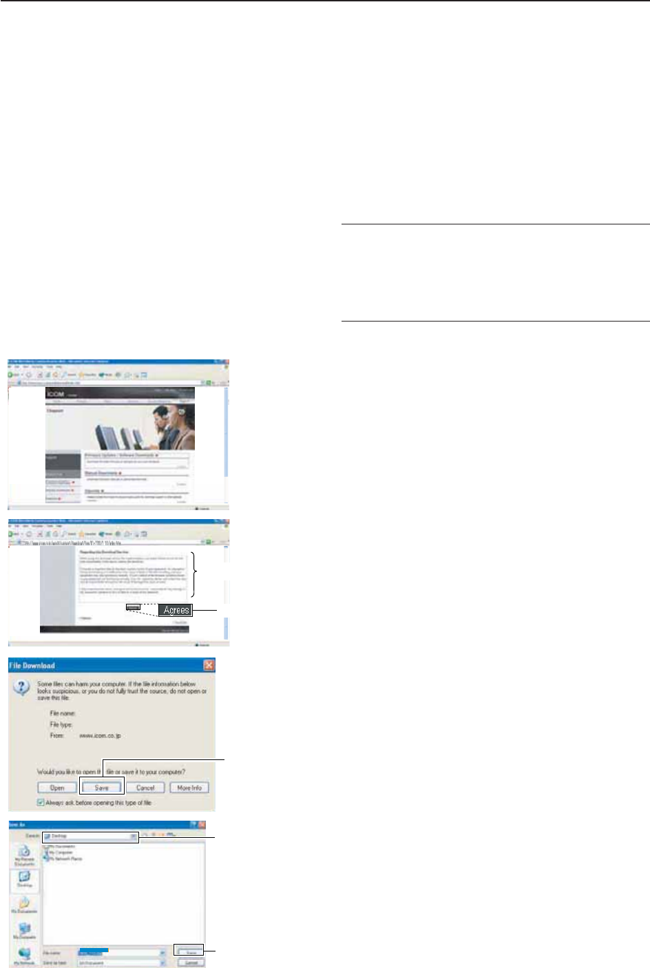
16-3
■Preparation
D
Firmware and firm utility
The latest firmware and the firm utility can be down-
loaded from the Icom home page via the Internet. Ac-
cess the following URL to download the firm utility and
the latest firmware.
http://www.icom.co.jp/world/support/index.htm
For updating from the USB-Memory
When updating the firmware from the USB-Memory,
copy the downloaded firmware data (e.g. 7700_110.dat)
to the USB-Memory (in “IC-7700” folder) using an avail-
able USB port (USB hub may be required; purchased sep-
arately from your PC dealer).
D
File downloading
qAccess the following URL directly.
http://www.icom.co.jp/world/support/index.htm
wClick “Firmware Updates/Software Downloads” link
then click the firmware file link.
eRead “Regarding this Download Service” carefully,
then click [AGREE].
rClick [Save] in the displayed File Download dialog.
tSelect the desired location in which you want to
save the firmware, then click [Save] in the displayed
File Download dialog.
• File download starts.
yAfter download is completed, extract the file.
• The firmware and the firm utility are compressed in “zip”
format, respectively.
• When updating the transceiver using with the USB-
Memory, copy the extracted firmware (e.g.
7700_110.dat) to the USB-Memory IC-7700 folder.
• The USB-Memory must have been formatted by the IC-
7700. (p. 12-26)
Select the saving
location
Click
7700_110.dat
Click
16
UPDATING THE FIRMWARE
Click
Read carefully
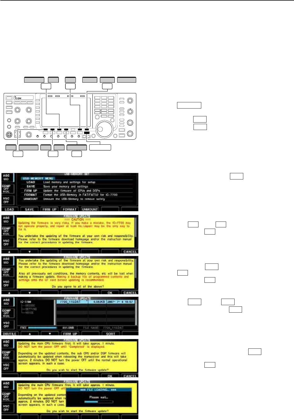
16-4
■Firmware update— USB-Memory
When updating the firmware with the USB-Memory, no
IP address or subnet mask settings are necessary.
qCopy the downloaded firmware data into the USB-
Memory (“IC-7700” folder).
• The USB-Memory must have been formatted by the IC-
7700.
wInsert the USB-Memory into the USB connector.
ePush several times to close a multi-func-
tion screen, if necessary.
rPush [SET] to select set mode menu screen.
tPush [USB] to select USB-Memory set menu.
yPush and hold [FIRM UP] for 1 sec.
uRead the displayed precaution carefully.
• Push [Y] or [Z] to scroll the indication.
• Push [CANCEL] to cancel the firmware updating.
iAfter you read and understand all of the precau-
tions, push [OK] .
• [OK] appears only following the precautions.
• Push [CANCEL] to cancel the firmware updating.
oPush [Y] or [Z] to select the firmware
file, then push [FIRM UP] .
!0 Read the displayed precautions carefully.
!1 If you agree, push and hold [OK] for 1 sec. to
start the firmware update.
• Push [CANCEL] to cancel the firmware updating.
!2 While loading the firmware from the USB-Memory,
the dialog as at left is displayed.
F-7
F-6
F-4
F-3F-2
F-7
F-6
F-6
F-7
F-2F-1
F-3
F-7
F-7
EXIT/SET
/
∫DIR/FILE
F-1
F-7
USB CANCELFIRM UP
FIRM UP
F-6
OK
F-3
F-4
/
SET //
/
F-2
√ ∫
√
EXIT/SET
16 UPDATING THE FIRMWARE
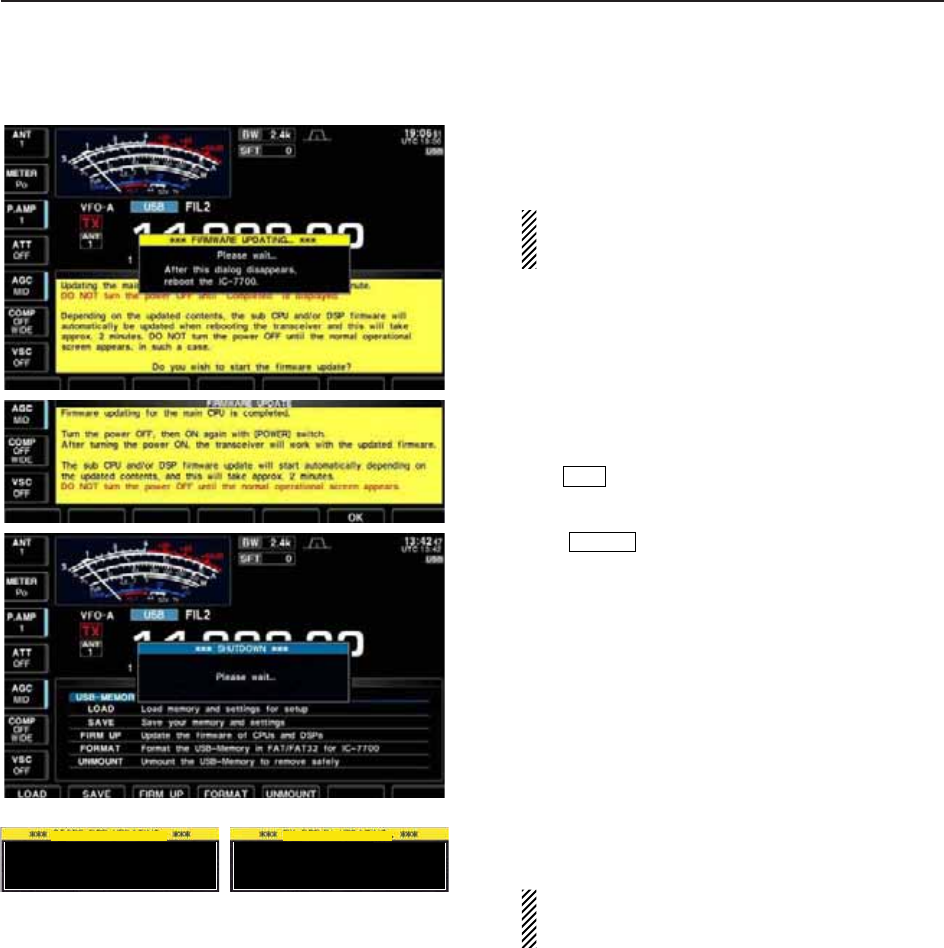
16-5
!3 After the firmware loading is completed, the trans-
ceiver starts the update automatically and the dia-
log at left is displayed.
RWARNING!: NEVER turn the IC-7700 power
OFF at this stage.
The transceiver firmware will be corrupted.
!4 When the dialog disappears, the precaution at left
is displayed.
!5 Read the precaution carefully, and then push
[OK] .
• Return to USB-Memory set menu.
!6 Push to turn the IC-7700 power OFF, then
ON again.
!7 Depending on the update, one or two dialog boxes
as at left appear in sequence.
RWARNING!: NEVER turn the IC-7700 power
OFF at this stage.
The transceiver firmware will be corrupted.
!8 After the dialog disappears, the firmware updating
is completed and normal operation screen appears.
POWER
F-6
Please wait for 10sec.
WARNING! NEVER turn power OFF.
Please wait for 25sec.
WARNING! NEVER turn power OFF.
TRX-DSP UPDATING...SCOPE-DSP UPDATING...
16
UPDATING THE FIRMWARE
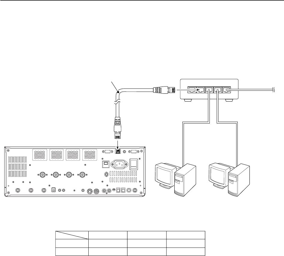
16-6
■Firmware update— PC
D
Connections Connect the IC-7700 and the PC through a LAN (Local
Area Network) as follows.
=××××
*Purchased separately
to WAN
/Internet network
Ethernet cable*
(Patch cable) to crossover port
• IP address setting example
Hub/Router*
IC-7700
(192.168.100.13)
PC1
(192.168.100.11)
PC2
(192.168.100.12)
PC1
192.168.100.11
255.255.255.0
IP address
Subnet mask
PC2
192.168.100.12
255.255.255.0
IC-7700
192.168.100.13
255.255.255.0
16 UPDATING THE FIRMWARE
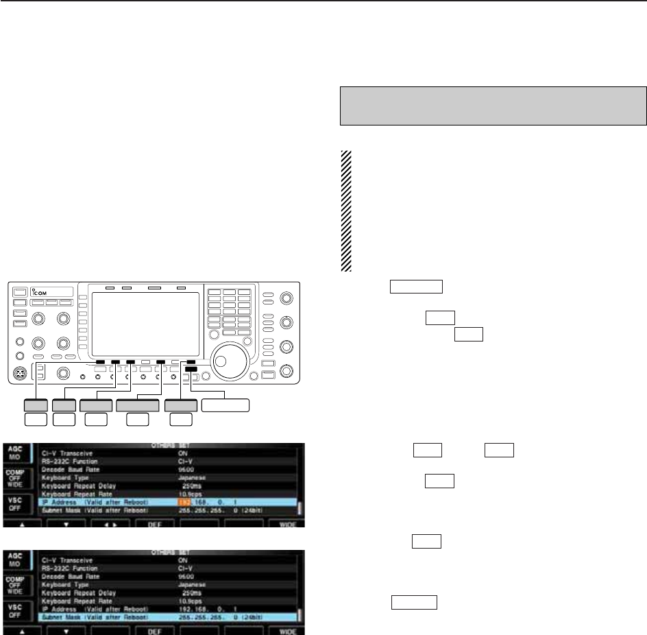
16-7
D
IP address setting
IMPORTANT!: A fixed (static) IP address is used for
the IC-7700.
When you connect the IC-7700 to a LAN, ask the
network manager about a usable/assignable IP
address and the subnet mask in advance.
NEVER use an IP address that has already been
used with another device in the network. If the IP
address is duplicated, the network will crash.
qPush several times to close a multi-func-
tion screen, if necessary.
wPush [SET] to select set mode menu screen.
ePush [OTHERS] to select Others set mode.
rPush [Y] or [Z] several times to select
“IP Address” item.
tPush [Ω≈] to select the desired part then ro-
tate the main dial to set the desired or specified IP
address.
• “192.168.0.1” is the default setting.
yPush [Z] to select “Subnet Mask” item.
uRotate the main dial to set the desired or specified
subnet mask.
• “255.255.255.0” is the default setting.
iPush to turn the transceiver power OFF,
then ON to enable the IP address and subnet mask
settings.
POWER
F-2
F-3
F-2F-1
F-5
F-7
EXIT/SET
When updating the firmware from the USB-Memory,
the following settings are not necessary.
F-2 F-3F-1
Ω ≈
F-5
OTHERS EXIT/SET
F-7
SET
∫ √
16
UPDATING THE FIRMWARE
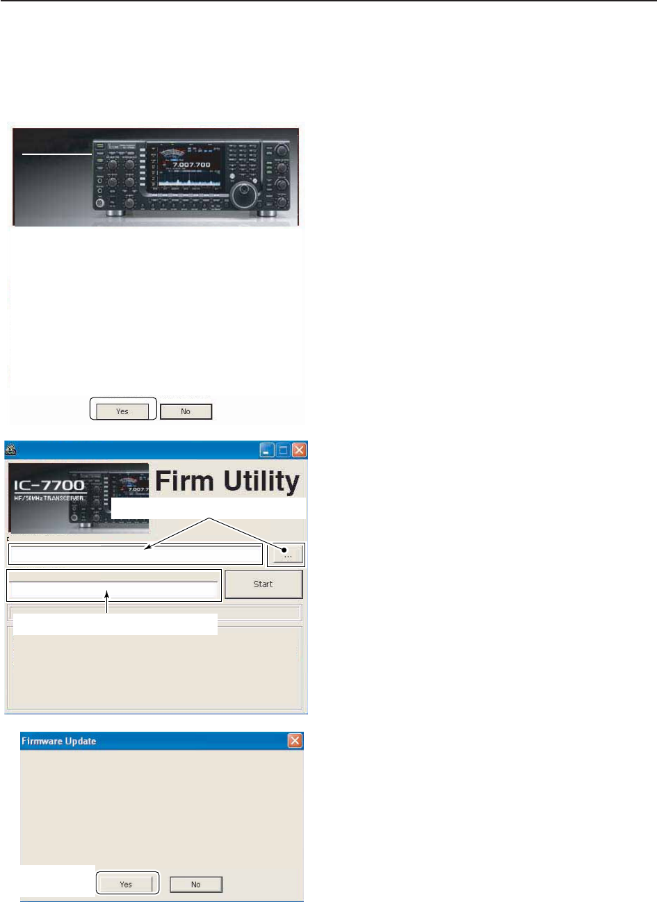
16-8
D
Updating from the PC
qStart up the IC-7700 Firm Utility.
• The window as at left appears.
wRead the caution in the window carefully.
eClick [Yes] if you agree and continue the firmware
updating.
rSelect the firmware file, that has “dat” extension
(e.g.: 7700_110.dat).
• Click […], then select the file, as well as the location.
tType the IC-7700’s IP address into “IC-7700 IP Ad-
dress” text box.
yClick [Start].
uThe window as at left appears.
Read the precaution in the window carefully.
iClick [Yes] if you want to start the firmware update.
Updating the main CPU firmware first.
It will take approx. 1 minute.
DO NOT turn the IC-7700 power OFF until "Completed" dialog is displayed.
Depending on the updated contents, the sub CPU and/or DSP firmware will
automatically be updated when rebooting the IC-7700 and this will take
approx. 2 minutes. DO NOT turn the IC-7700 power OFF until the normal
operational screen appears, in such case.
Do you wish to start the firmware update?
Click to start the
firmware update
IC-7700 IP Address
Version 1.00
(C) 2007 Icom Inc.
Firmware File Name
Turn the IC-7700 power ON.
When the normal operational screen appears, set the firmware file name
and IP address, then click [Start] button.
IC-7700 Firm Utility
Click [ ] to select the firmware file.
Type the IC-7700 s IP address here.
Do you agree to all of the above?
i7700
HF/50MHz TRANSCEIVER
Firm Utility
===CAUTION===
Updating the firmware is very risky. If you make a mistake, the IC-7700 may
not operate properly, and repair at Icom Inc.(Japan) may be the only way to
fix it.
You undertake the updating of the firmware at you own risk and responsibility,
Please refer to the firmware download homepage and/or the instruction manual
for the correct procedures in updating the firmware.
Also all preciously set conditions, the memory contents, etc will be lost when
making a firmware update.
Making a backup file of programmed contents and settings onto the USB-
Memory before updating is recommended.
Click to
continue
16 UPDATING THE FIRMWARE
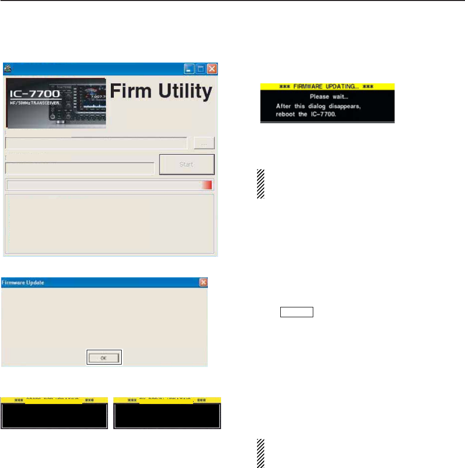
16-9
oThe screen as at left is displayed.
• The following dialog appears in the IC-7700 display.
RWARNING!: NEVER turn the IC-7700 power
OFF at this stage.
The transceiver firmware will be corrupted.
!0 Click [OK] to finish the firmware update.
• The “FIRMWARE UPDATING” dialog as above disap-
pears.
!1 Push to turn the IC-7700 power OFF, then
ON again.
!2 Depending on the update, one or two dialog boxes
as at left appear on the IC-7700 display in se-
quence.
RWARNING!: NEVER turn the IC-7700 power
OFF at this stage.
The transceiver firmware will be corrupted.
!3 After the dialog disappears, the firmware update is
completed and normal operation screen appears.
POWER
Please wait for 10sec.
WARNING! NEVER turn power OFF.
Please wait for 25sec.
WARNING! NEVER turn power OFF.
TRX-DSP UPDATING...SCOPE-DSP UPDATING...
Firmware up dating for the main CPU is completed.
The sub CPU and/or DSP firmware update will start automatically depending on the updated contents,
and this will take approx. 2 minutes.
Turn the IC-7700 power OFF, then ON again with [POWER] switch.
After turning the power ON, the IC-7700 will work with the updated firmware.
DO NOT turn the IC-7700 power OFF until the normal operational screen appears.
Click [OK] to finish the firmware update.
IC-7700 IP Address
IC-7700 IP Address
Firmware File Name
Version 1.00
(C) 2007 Icom Inc.
Firmware File Name
Connecting to the IC-7700.
Connected to the IC-7700.
Transfer in progress...
Transfer successful.
Start update.
Please wait a while.
IC-7700 Firm Utility
16
UPDATING THE FIRMWARE
INSTALLATION NOTES
For amateur base station installations it is recom-
mended that the clearance in front of the antenna array
is calculated relative to the EIRP (Effective Isotropic
Radiated Power). The clearance height below the an-
tenna array can be determined in most cases from the
RF power at the antenna input terminals.
Different exposure limits have been recommended for
different frequencies, a relative table shows a guide-
line for installation considerations.
Below 30 MHz, the recommended limits are specified
in terms of V/m or A/m fields as they are likely to fall
within the near-field region. Similarly, the antennas
may be physically short in terms of electrical length
and that the installation will require some antenna
matching device which can create local, high intensity
magnetic fields. Analysis of such installations is best
considered in association with published guidance
notes such as the FCC OET Bulletin 65 Edition 97-01
and its annexes relative to amateur transmitter instal-
lations. The EC recommended limits are almost identi-
cal to the FCC specified ‘uncontrolled’ limits and tables
exist that show pre-calculated safe distances for differ-
ent antenna types for different frequency bands. Fur-
ther information can be found at http://www.arrl.org/.
• Typical amateur radio installation
Exposure distance assumes that the predominant ra-
diation pattern is forward and that radiation downward
is at unity gain (side lobe suppression is equal to main
lobe gain). This is true of almost every gain antenna
today. Exposed persons are assumed to be beneath
the antenna array and have a typical height of 1.8 m.
The figures assume the worst-case emission of con-
stant carrier.
For the bands 10 MHz and higher the following power
density limits have been recommended:
10–144 MHz 2 W/sq m
EIRP clearance heights by frequency band
1 Watts 2.1 m
10 Watts 2.8 m
25 Watts 3.4 m
100 Watts 5 m
1000 Watts 12 m
Forward clearance, EIRP by frequency band
100 Watts 2 m
1000 Watts 6.5 m
10,000 Watts 20 m
100,000 Watts 65 m
In all cases any possible risk depends on the transmit-
ter being activated for long periods. (actual recom-
mendation limits are specified as an average during 6
minutes) Normally the transmitter is not active for long
periods of time. Some radio licenses will require that a
timer circuit automatically cuts the transmitter after 1–2
minutes etc.
Similarly some types of emission, i.e., SSB, CW, AM
etc. have a lower ‘average’ output power and the as-
sessed risk is even lower.
Versions of the IC-7700 which display the
“CE” symbol on the serial number seal,
comply with the essential requirements of
the European Radio and Telecommunication
Terminal Directive 1999/5/EC.
This warning symbol indicates that this
equipment operates in non-harmonised fre-
quency bands and/or may be subject to li-
censing conditions in the country of use. Be
sure to check that you have the correct ver-
sion of this radio or the correct programming
of this radio, to comply with national licens-
ing requirement.
• List of Country codes (ISO 3166-1)
ABOUT CE
1 Austria AT
2 Belgium BE
3 Bulgaria BG
4 Croatia HR
5 Czech Republic CZ
6 Cyprus CY
7 Denmark DK
8 Estonia EE
9 Finland FI
10 France FR
11 Germany DE
12 Greece GR
13 Hungary HU
14 Iceland IS
15 Ireland IE
16 Italy IT
17 Latvia LV
18 Liechtenstein LI
19 Lithuania LT
20 Luxembourg LU
21 Malta MT
22 Netherlands NL
23 Norway NO
24 Poland PL
25 Portugal PT
26 Romania RO
27 Slovakia SK
28 Slovenia SI
29 Spain ES
30 Sweden SE
31 Switzerland CH
32 Turkey TR
33 United Kingdom GB
Country Codes Country Codes

ABOUT CE
DECLARATION
OF CONFORMITY
Düsseldorf 30th Nov.2007
Place and date of issue
Icom (Europe) GmbH
Himmelgeister straße 100
D-40225 Düsseldorf
Authorized representative name
H. Ikegami
General Manager
Signature
We Icom Inc. Japan
1-1-32, Kamiminami, Hirano-ku
Osaka 547-0003, Japan
Declare on our sole responsibility that this equipment complies with the
essential requirements of the Radio and Telecommunications Terminal
Equipment Directive, 1999/5/EC, and that any applicable Essential Test
Suite measurements have been performed.
Kind of equipment: HF/50 MHz ALL MODE TRANSCEIVER
Type-designation: i7700
Version (where applicable):
This compliance is based on conformity with the following harmonised
standards, specifications or documents:
i) EN 301489-1 v1.4.1 (2002-08)
ii) EN 301489-15 v1.2.1 (2002-08)
iii) EN 301 783 v1.1.1 (2000-09)
iv) EN 60950-1 (2001):A11:2004
iv)v)

Please record the serial number of your IC-7700 transceiver below for future servicing
reference:
Serial Number :
Date of purchase :
Place where purchased :

1-1-32 Kamiminami, Hirano-ku, Osaka 547-0003, Japan
<Intended Country of Use>
■
AT
■
BE
■
CY
■
CZ
■
DK
■
EE
■
FI
■
FR
■
DE
■
GR
■
HU
■
IE
■
IT
■
LV
■
LT
■
LU
■
MT
■
NL
■
PL
■
PT
■
SK
■
SI
■
ES
■
SE
■
GB
■
IS
■
LI
■
NO
■
CH
■
BG
■
RO
■
TR
■
HR
<Intended Country of Use>
■
AT
■
BE
■
CY
■
CZ
■
DK
■
EE
■
FI
■
FR
■
DE
■
GR
■
HU
■
IE
■
IT
■
LV
■
LT
■
LU
■
MT
■
NL
■
PL
■
PT
■
SK
■
SI
■
ES
■
SE
■
GB
■
IS
■
LI
■
NO
■
CH
■
BG
■
RO
■
TR
■
HR
<Intended Country of Use>
■
AT
■
BE
■
CY
■
CZ
■
DK
■
EE
■
FI
■
FR
■
DE
■
GR
■
HU
■
IE
■
IT
■
LV
■
LT
■
LU
■
MT
■
NL
■
PL
■
PT
■
SK
■
SI
■
ES
■
SE
■
GB
■
IS
■
LI
■
NO
■
CH
■
BG
■
RO
■
TR
■
HR
<Intended Country of Use>
■
AT
■
BE
■
CY
■
CZ
■
DK
■
EE
■
FI
■
FR
■
DE
■
GR
■
HU
■
IE
■
IT
■
LV
■
LT
■
LU
■
MT
■
NL
■
PL
■
PT
■
SK
■
SI
■
ES
■
SE
■
GB
■
IS
■
LI
■
NO
■
CH
■
BG
■
RO
■
TR
■
HR
<Intended Country of Use>
■
AT
■
BE
■
CY
■
CZ
■
DK
■
EE
■
FI
■
FR
■
DE
■
GR
■
HU
■
IE
■
IT
■
LV
■
LT
■
LU
■
MT
■
NL
■
PL
■
PT
■
SK
■
SI
■
ES
■
SE
■
GB
■
IS
■
LI
■
NO
■
CH
■
BG
■
RO
■
TR
■
HR
IC-7700
#03 (Europe)
IC-7700
#04 (France)
IC-7700
#07 (United
Kingdom)
IC-7700
#05 (Italy)
IC-7700
#06 (Spain)