ICOM orporated 300900 HF/50 MHz Transceiver User Manual IC 7700 ENG
ICOM Incorporated HF/50 MHz Transceiver IC 7700 ENG
Contents
- 1. User Manual Part 1
- 2. User Manual Part 2
User Manual Part 1
HF/50 MHz TRANSCEIVER
i7700
Instruction Manual
A-6612H-1EX
Printed in Japan
© 2007 Icom Inc.
i
FOREWORD
Thank you for making the IC-7700 your radio of choice. We hope you agree
with Icom’s philosophy of “technology first.” Many hours of research and
development went into the design of your IC-7700.
D
FEATURES
❍Ultimate receiver performance: third-order intercept (IP3)
of +40 dBm (HF bands only)
❍Built-in Baudot RTTY and PSK31 modulator/demodulator
and direct PC keyboard connection capability for RTTY
and PSK31 operation without a PC
❍High resolution spectrum scope— center frequency and
fixed frequency modes, plus mini-scope displays
IMPORTANT
READ THIS INSTRUCTION MANUAL CAREFULLY before at-
tempting to operate the transceiver.
SAVE THIS INSTRUCTION MANUAL. This manual contains im-
portant safety and operating instructions for the IC-7700.
EXPLICIT DEFINITIONS
TRADEMARKS
Icom, Icom Inc. and the logo are registered trademarks of Icom
Incorporated (Japan) in the United States, the United Kingdom, Germany,
France, Spain, Russia and/or other countries.
WORD DEFINITION
R
WARNING Personal injury, fire hazard or electric shock may
occur.
CAUTION Equipment damage may occur.
NOTE If disregarded, inconvenience only. No risk of person-
al injury, fire or electric shock.

ii
PRECAUTIONS
RWARNING HIGH RF VOLTAGE! NEVER
attach an antenna or internal antenna connector during
transmission. This may result in an electrical shock or
burn.
RWARNING! NEVER operate the transceiver
with a headset or other audio accessories at high vol-
ume levels. Hearing experts advise against continuous
high volume operation. If you experience a ringing in
your ears, reduce the volume or discontinue use.
RWARNING! Immediately turn the transceiver
power OFF and remove the power cable if it emits an
abnormal odor, sound or smoke. Contact your Icom
dealer or distributor for advice.
RCAUTION! NEVER put the transceiver in any
unstable place (such as on a slanted surface or vi-
brated place). This may cause injuly and/or damage to
the transceiver.
RCAUTION! NEVER put the transceiver’s rear
panel side down after lifting up the transceiver by hold-
ing rack mounting handle. This may scratch the sur-
face of the place or damage the connectors on the
transceiver’s rear panel.
RCAUTION! NEVER change the internal set-
tings of the transceiver. This may reduce transceiver
performance and/or damage to the transceiver.
In particular, incorrect settings for transmitter circuits,
such as output power, idling current, etc., might dam-
age the expensive final devices.
The transceiver warranty does not cover any problems
caused by unauthorized internal adjustment.
RCAUTION! NEVER touch the transceiver top
cover when transmitting continuously for long periods.
The top cover may be hot.
RCAUTION! NEVER let metal, wire or other ob-
jects protrude into the transceiver or into connectors
on the rear panel. This may result in an electric shock.
RCAUTION! NEVER block any cooling vents on
the top, rear or bottom of the transceiver.
RCAUTION! NEVER expose the transceiver to
rain, snow or any liquids.
RCAUTION! NEVER install the transceiver in a
place without adequate ventilation. Heat dissipation
may be reduced, and the transceiver may be dam-
aged.
RCAUTION! NEVER operate or touch the trans-
ceiver with wet hands. This may result in an electric
shock or damage to the transceiver.
RCAUTION! The transceiver weighs approx. 22.5
kg (50 lb). Always have two people available to carry,
lift or turn over the transceiver.
RCAUTION! The line-voltage receptacle must be
near the transceiver and must be easily accessible.
Avoid extension cords.
DO NOT
use chemical agents such as benzine or al-
cohol when cleaning the IC-7700, as they can damage
the transceiver’s surfaces.
DO NOT push the PTT switch when you don’t actu-
ally desire to transmit.
AVOID using or storing the transceiver in areas with
temperatures below ±0°C (+32°F) or above +50°C
(+122°F).
AVOID placing the transceiver in excessively dusty en-
vironments or in direct sunlight.
AVOID placing the transceiver against walls or putting
anything on top of the transceiver. This may overheat
the transceiver.
Always place unit in a secure place to avoid inadver-
tent use by children.
BE CAREFUL! If you use a linear amplifier, set the
transceiver’s RF output power to less than the linear
amplifier’s maximum input level, otherwise, the linear
amplifier will be damaged.
Use Icom microphones only (supplied or optional).
Other manufacturers’ microphones have different pin
assignments, and connection to the IC-7700 may dam-
age the transceiver or microphone.
The LCD display may have cosmetic imperfections that
appear as small dark or light spots. This is not a mal-
function or defect, but a normal characteristic of LCD
displays.
During maritime mobile operation, keep the transceiver
and microphone as far away as possible from the mag-
netic navigation compass to prevent erroneous indica-
tions.
Turn [I/O] switch (on the rear panel) OFF and/or dis-
connect the AC power cable from the AC outlet when
you will not use the transceiver for long period of time.
For U.S.A. only
CAUTION: Changes or modifications to this device,
not expressly approved by Icom Inc., could void your
authority to operate this device under FCC regulations.
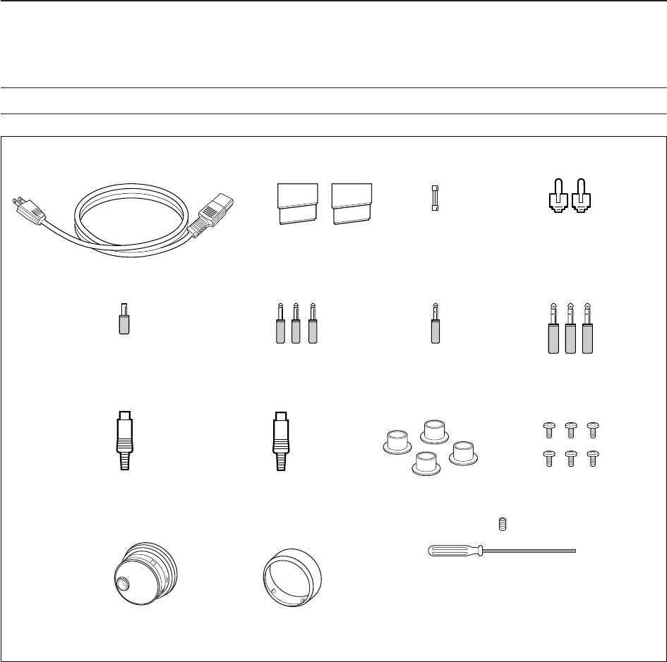
qAC power cable* ………………………………… 1
wFeet …………………………………………… 1 pair
eSpare fuse (FGB 2 A) …………………………… 1
rRCA plugs ………………………………………… 2
tDC plug …………………………………………… 1
y2-conductor 1⁄8wplugs …………………………… 3
u3-conductor 1⁄8wplugs …………………………… 2
i3-conductor 1⁄4wplugs …………………………… 3
oACC plugs (7-pin) ………………………………… 1
!0 ACC plugs (8-pin) ………………………………… 1
!1 Antenna connector caps ………………………… 4
!2 Side screws (without rack mounting handle)†…6
!3 Main dial‡…………………………………………… 1
!4 Rubber cover for Main dial‡……………………… 1
!5 Main dial screw and hexagonal wrench‡…… 1 set
*May differ from that shown according to version.
†These screw are used when removing rack mounting han-
dles. See p.2-3 for rack mounting handle detachment de-
tails.
‡See p.2-2 for main dial attachment details.
iii
SUPPLIED ACCESSORIES
q
!0 !1 !2
!3 !4 !5
yui
o
ewr
t

iv
Section 1 PANEL DESCRIPTION
■Front panel ……………………………………………………………… 1-2
■Rear panel ……………………………………………………………… 1-12
■LCD display …………………………………………………………… 1-14
■Screen menu arrangement …………………………………………… 1-16
Section 2 INSTALLATION AND CONNECTIONS
■Unpacking ……………………………………………………………… 2-2
■Main dial attachment …………………………………………………… 2-2
■Rack mounting handle detachment …………………………………… 2-3
■Selecting a location …………………………………………………… 2-3
■Grounding ……………………………………………………………… 2-4
■Antenna connection …………………………………………………… 2-4
■USB-Memory connection ……………………………………………… 2-4
■Required connections ………………………………………………… 2-5
DFront panel …………………………………………………………… 2-5
DRear panel …………………………………………………………… 2-5
■Advanced connections ………………………………………………… 2-6
DFront panel …………………………………………………………… 2-6
DRear panel—1 ……………………………………………………… 2-6
DRear panel—2 ……………………………………………………… 2-7
■Linear amplifier connections …………………………………………… 2-8
DConnecting the IC-PW1/EURO …………………………………… 2-8
DConnecting a non-Icom linear amplifier …………………………… 2-8
■Transverter jack information …………………………………………… 2-9
■FSK and AFSK (SSTV) connections ………………………………… 2-9
■Microphone connector information ………………………………… 2-10
■Microphones (options) ………………………………………………… 2-10
DSM-20 ……………………………………………………………… 2-10
DHM-36 ……………………………………………………………… 2-10
■Accessory connector information …………………………………… 2-11
Section 3 BASIC OPERATIONS
■When first applying power (CPU resetting) ………………………… 3-2
■Initial settings …………………………………………………………… 3-2
■Selecting VFO/memory mode ………………………………………… 3-3
■VFO selection …………………………………………………………… 3-3
DSelecting VFO-A/VFO-B …………………………………………… 3-3
DVFO equalization …………………………………………………… 3-3
■Selecting an operating band …………………………………………… 3-4
DUsing the band stacking registers ………………………………… 3-4
■Frequency setting ……………………………………………………… 3-5
DTuning with the main dial …………………………………………… 3-5
DDirect frequency entry with the keypad …………………………… 3-5
DQuick tuning step …………………………………………………… 3-6
DSelecting “kHz” step ………………………………………………… 3-6
D1⁄4tuning step function ……………………………………………… 3-6
DSelecting 1 Hz step ………………………………………………… 3-7
DAuto tuning step function …………………………………………… 3-7
DBand edge warning beep …………………………………………… 3-7
■Operating mode selection ……………………………………………… 3-8
■Volume setting ………………………………………………………… 3-9
■RF gain adjustment …………………………………………………… 3-9
■Squelch level adjustment ……………………………………………… 3-9
TABLE OF CONTENTS

■Meter indication selection …………………………………………… 3-10
DMulti-function digital meter ………………………………………… 3-10
DMeter type selection ……………………………………………… 3-11
■Voice synthesizer operation ………………………………………… 3-11
■Basic transmit operation ……………………………………………… 3-12
DTransmitting ………………………………………………………… 3-12
DMicrophone gain adjustment ……………………………………… 3-12
DDrive gain adjustment ……………………………………………… 3-13
Section 4 RECEIVE AND TRANSMIT
■Operating SSB ………………………………………………………… 4-2
DConvenient functions for receive ……………………………………4-2
DConvenient functions for transmit ……………………………………4-3
DAbout 5 MHz band operation (USA version only) …………………4-3
■Operating CW …………………………………………………………… 4-4
DConvenient functions for receive ……………………………………4-4
DConvenient functions for transmit ……………………………………4-5
DAbout CW reverse mode ……………………………………………4-5
DAbout CW pitch control ………………………………………………4-5
DCW side tone function ………………………………………………4-5
DAPF (Audio Peak Filter) operation …………………………………4-6
■Electronic keyer functions ……………………………………………… 4-7
DMemory keyer screen …………………………………………………4-8
DEditing a memory keyer ………………………………………………4-9
DContest number set mode …………………………………………4-10
DKeyer set mode ………………………………………………………4-11
■Operating RTTY (FSK) ……………………………………………… 4-13
DConvenient functions for receive …………………………………4-14
DAbout RTTY reverse mode …………………………………………4-14
DTwin peak filter ………………………………………………………4-14
DFunctions for the RTTY decoder indication ………………………4-15
DSetting the decoder threshold level ………………………………4-15
DRTTY memory transmission ………………………………………4-16
DAutomatic transmission/reception setting …………………………4-16
DEditing RTTY memory ………………………………………………4-17
DRTTY decode set mode ……………………………………………4-18
DData saving …………………………………………………………4-20
■Operating PSK ………………………………………………………… 4-21
DConvenient functions for receive …………………………………4-22
DAbout BPSK and QPSK modes ……………………………………4-22
DFunctions for the PSK decoder indication ………………………4-23
DSetting the decoder threshold level ………………………………4-23
DPSK memory transmission …………………………………………4-24
DAutomatic transmission/reception setting …………………………4-24
DEditing PSK memory ………………………………………………4-25
DPSK decode set mode ………………………………………………4-26
DData saving …………………………………………………………4-28
■Operating AM ………………………………………………………… 4-29
DConvenient functions for receive …………………………………4-29
DConvenient functions for transmit …………………………………4-30
■Operating FM ………………………………………………………… 4-31
DConvenient functions for receive …………………………………4-31
DConvenient functions for transmit …………………………………4-31
v
TABLE OF CONTENTS

vi
■Repeater operation …………………………………………………… 4-32
DRepeater tone frequency setting …………………………………4-33
■Tone squelch operation ……………………………………………… 4-34
■Data mode (AFSK) operation ………………………………………… 4-35
Section 5 FUNCTIONS FOR RECEIVE
■Spectrum scope screen ……………………………………………… 5-2
DCenter mode ………………………………………………………… 5-2
DFixed mode …………………………………………………………… 5-3
DMini scope screen indication ……………………………………… 5-4
DScope set mode ……………………………………………………… 5-4
■Preamplifier ……………………………………………………………… 5-9
■Attenuator ……………………………………………………………… 5-9
■RIT function …………………………………………………………… 5-10
DRIT monitor function …………………………………………………5-10
■AGC function …………………………………………………………… 5-11
DSelecting the preset value …………………………………………5-11
DAdjusting the AGC time constant …………………………………5-11
DSetting the AGC time constant preset value ………………………5-11
■Twin PBT operation …………………………………………………… 5-12
■IF filter selection ……………………………………………………… 5-13
DIF filter selection …………………………………………………… 5-13
DFilter passband width setting (except FM mode) ……………… 5-13
DRoofing filter selection ……………………………………………… 5-14
DDSP filter shape …………………………………………………… 5-14
DFilter shape set mode ……………………………………………… 5-14
■Noise blanker ………………………………………………………… 5-16
DNB set mode ………………………………………………………… 5-16
■Noise reduction ………………………………………………………… 5-17
■Dial lock function ……………………………………………………… 5-17
■Notch function ………………………………………………………… 5-18
■Digital selector ………………………………………………………… 5-18
■Autotune function ……………………………………………………… 5-19
Section 6 FUNCTIONS FOR TRANSMIT
■VOX function …………………………………………………………… 6-2
DUsing the VOX function …………………………………………… 6-2
DAdjusting the VOX function ………………………………………… 6-2
DVOX set mode ……………………………………………………… 6-2
■Break-in function ………………………………………………………… 6-3
DSemi break-in operation …………………………………………… 6-3
DFull break-in operation ……………………………………………… 6-3
■∂TX function …………………………………………………………… 6-4
D∂TX monitor function ………………………………………………… 6-4
■Monitor function ………………………………………………………… 6-4
■Transmit filter width setting (SSB only) ……………………………… 6-5
■Speech compressor (SSB only) ……………………………………… 6-5
■Split frequency operation ……………………………………………… 6-6
■Quick split function ……………………………………………………… 6-7
DSplit lock function …………………………………………………… 6-7
TABLE OF CONTENTS

Section 7 VOICE RECORDER FUNCTIONS
■About digital voice recorder …………………………………………… 7-2
■Recording a received audio …………………………………………… 7-3
DBasic recording ……………………………………………………… 7-3
DOne-touch recording ………………………………………………… 7-3
■Playing the recorded audio …………………………………………… 7-4
DBasic playing ………………………………………………………… 7-4
DOne-touch playing …………………………………………………… 7-4
■Protect the recorded contents ………………………………………… 7-5
■Erasing the recorded contents ………………………………………… 7-5
■Recording a message for transmit …………………………………… 7-6
DRecording …………………………………………………………… 7-6
DConfirming a message for transmit ………………………………… 7-6
■Programming a memory name ……………………………………… 7-7
■Sending a recorded message ………………………………………… 7-8
DTransmit level setting ……………………………………………… 7-8
■Voice set mode ………………………………………………………… 7-9
■Saving a voice memory into the USB-Memory …………………… 7-10
DSaving the received audio memory ……………………………… 7-10
DSaving the TX memory …………………………………………… 7-10
Section 8 MEMORY OPERATION
■Memory channels ……………………………………………………… 8-2
■Memory channel selection …………………………………………… 8-2
DUsing the / keys ………………………………………… 8-2
DUsing the keypad …………………………………………………… 8-2
■Memory channel programming ……………………………………… 8-3
DProgramming in VFO mode ………………………………………… 8-3
DProgramming in memory mode …………………………………… 8-3
■Frequency transferring ………………………………………………… 8-4
DTransferring in VFO mode ………………………………………… 8-4
DTransferring in memory mode ……………………………………… 8-4
■Memory list screen ……………………………………………………… 8-5
DSelecting a memory channel using the memory list screen …… 8-5
DConfirming programmed memory channels ……………………… 8-5
■Memory names ………………………………………………………… 8-6
DEditing (programming) memory names …………………………… 8-6
■Memory clearing ………………………………………………………… 8-6
■Memo pads ……………………………………………………………… 8-7
DWriting frequencies and operating modes into memo pads …… 8-7
DCalling up a frequency from a memo pad ………………………… 8-7
Section 9 SCANS
■Scan types ……………………………………………………………… 9-2
■Preparation ……………………………………………………………… 9-2
■Voice squelch control function ………………………………………… 9-3
■Scan set mode ………………………………………………………… 9-3
■Programmed scan operation ………………………………………… 9-4
■∂F scan operation ……………………………………………………… 9-4
■Fine programmed scan/Fine ∂F scan ……………………………… 9-5
■Memory scan operation ………………………………………………… 9-6
■Select memory scan operation ……………………………………… 9-6
√
∫
vii
TABLE OF CONTENTS

viii
■Setting select memory channels ……………………………………… 9-7
DSetting in scan screen ……………………………………………… 9-7
DSetting in memory list screen ……………………………………… 9-7
DErasing the select scan setting …………………………………… 9-7
■Tone scan ……………………………………………………………… 9-8
Section 10 ANTENNA TUNER OPERATION
■Antenna connection and selection ………………………………… 10-2
■Antenna memory settings …………………………………………… 10-3
DAntenna type selection …………………………………………… 10-3
DTemporary memory ………………………………………………… 10-4
DAntenna selection mode …………………………………………… 10-4
DReceive antenna I/O setting ……………………………………… 10-5
■Antenna tuner operation ……………………………………………… 10-6
DTuner operation …………………………………………………… 10-6
DIf the tuner cannot tune the antenna …………………………… 10-7
Section 11 CLOCK AND TIMERS
■Time set mode ………………………………………………………… 11-2
■Daily timer setting ……………………………………………………… 11-3
■Setting sleep timer …………………………………………………… 11-4
■Timer operation ………………………………………………………… 11-4
Section 12 SET MODE
■Set mode description ………………………………………………… 12-2
DSet mode operation ………………………………………………… 12-2
DScreen arrangement ……………………………………………… 12-3
■Level set mode ………………………………………………………… 12-4
■ACC set mode ………………………………………………………… 12-7
■Display set mode ……………………………………………………… 12-9
■Others set mode …………………………………………………… 12-12
■USB-Memory set menu …………………………………………… 12-19
DUSB-Memory set screen arrangement ………………………… 12-19
DSave option set mode …………………………………………… 12-20
DLoad option set mode …………………………………………… 12-21
■File saving …………………………………………………………… 12-22
■File loading …………………………………………………………… 12-23
■Changing a file name ……………………………………………… 12-24
■Deleting a file ………………………………………………………… 12-25
■Unmounting USB-Memory ………………………………………… 12-25
■Formatting the USB-Memory ……………………………………… 12-26
Section 13 MAINTENANCE
■Troubleshooting ……………………………………………………… 13-2
DTransceiver power ………………………………………………… 13-2
DTransmit and receive ……………………………………………… 13-2
DScanning …………………………………………………………… 13-3
DDisplay ……………………………………………………………… 13-3
DFormat USB-Memory ……………………………………………… 13-3
■Main dial brake adjustment ………………………………………… 13-3
■SWR reading …………………………………………………………… 13-4
■Screen type and font selections …………………………………… 13-4
■Frequency calibration (approximate) ……………………………… 13-5
■Opening the transceiver’s case ……………………………………… 13-6
■Clock backup battery replacement ………………………………… 13-6
TABLE OF CONTENTS

■Fuse replacement …………………………………………………… 13-7
■Resetting the CPU …………………………………………………… 13-7
■About protection indications ………………………………………… 13-8
■Screen saver function ………………………………………………… 13-8
Section 14 CONTROL COMMAND
■Remote jack (CI-V) information ……………………………………… 14-2
DCI-V connection example ………………………………………… 14-2
DData format ………………………………………………………… 14-2
DCommand table …………………………………………………… 14-3
DTo send/read memory contents …………………………………… 14-9
DBand stacking register …………………………………………… 14-9
DCodes for memory keyer contents ……………………………… 14-9
DCodes for memory name, opening message
and CLOCK2 name contents ……………………………………… 14-9
DOffset frequency setting ………………………………………… 14-10
DRepeater tone/tone squelch frequency setting ………………… 14-10
DSSB transmission passband width setting …………………… 14-10
DColor setting ……………………………………………………… 14-10
DBandscope edge frequency setting …………………………… 14-10
DData mode with filter width setting ……………………………… 14-10
DAntenna memory setting ………………………………………… 14-10
Section 15 SPECIFICATIONS AND OPTIONS
■Specifications ………………………………………………………… 15-2
DGeneral ……………………………………………………………… 15-2
DTransmitter ………………………………………………………… 15-2
DReceiver …………………………………………………………… 15-3
DAntenna tuner ……………………………………………………… 15-3
■Options ………………………………………………………………… 15-4
Section 16 UPDATING THE FIRMWARE
■General ………………………………………………………………… 16-2
■Caution ………………………………………………………………… 16-2
■Preparation …………………………………………………………… 16-3
DFirmware and firm utility …………………………………………… 16-3
DFile downloading …………………………………………………… 16-3
■Firmware update— USB-Memory …………………………………… 16-4
■Firmware update— PC ……………………………………………… 16-6
DConnections ………………………………………………………… 16-6
DIP address setting ………………………………………………… 16-7
DUpdating from the PC ……………………………………………… 16-8
ix
TABLE OF CONTENTS

1-1
PANEL DESCRIPTION Section 1
■Front panel ……………………………………………………………… 1-2
■Rear panel ……………………………………………………………… 1-12
■LCD display …………………………………………………………… 1-14
■Screen menu arrangement …………………………………………… 1-16
1-2
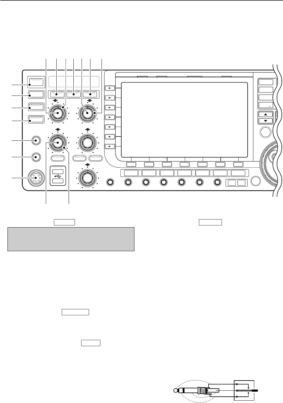
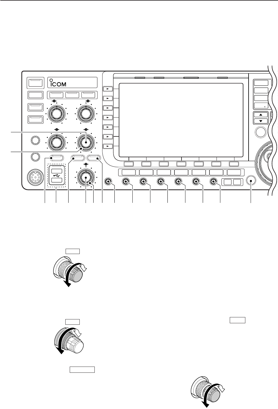
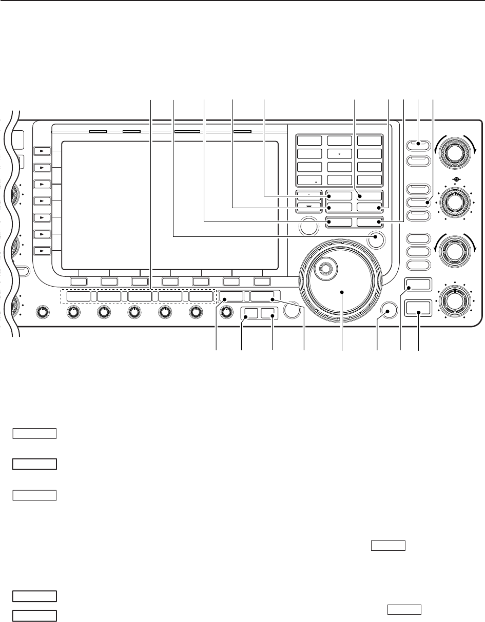
qPOWER SWITCH (p. 3-2)
➥Push to turn the transceiver power ON.
• The [POWER] indicator above this switch lights green
when powered ON.
➥Push and hold for 1 sec. to turn the transceiver
power OFF.
• The [POWER] indicator lights orange when the trans-
ceiver is OFF when the internal power supply is
switched ON.
wTRANSMIT SWITCH
Selects transmit or receive.
• The [TX] indicator lights red while transmitting and the
[RX] indicator lights green when the squelch is open.
eANTENNA TUNER SWITCH (p. 10-6)
➥Turns the internal antenna tuner ON and OFF
(bypass) when pushed momentarily.
• The [TUNER] indicator above this switch lights green
when the tuner is turned ON, goes off when tuner is
turned OFF (bypassed).
➥Tunes the antenna tuner manually when pushed
and held for 1 sec.
• The [TUNER] indicator blinks red during manual tun-
ing.
• When the tuner cannot tune the antenna, the tuning
circuit is bypassed automatically after 20 sec.
rTIMER SWITCH (p. 11-4)
➥Turns the sleep or daily timer function ON and
OFF.
• The [TIMER] indicator above this switch lights green
when the timer is in use.
➥Enters timer set mode when pushed and held for
1 sec.
tHEADPHONE JACK [PHONES]
Accepts standard stereo headphones.
• Output power: 5 mW with an 8 load.
• When headphones are connected, the internal speaker
or connected external speaker does not function.
yELECTRONIC KEYER JACK [ELEC-KEY] (p. 2-5)
Accepts a paddle to activate the internal electronic
keyer for CW operation.
• You can select internal electronic keyer, bug-key or
straight key operation in keyer set mode. (p. 4-12)
• A straight key jack is located on the rear panel. See [CW
KEY] on p. 1-12.
• Keyer polarity (dot and dash) can be reversed in keyer
set mode. (p. 4-12)
• 4-channel memory keyer is available for your conve-
nience. (p. 4-8)
TIMER
TUNER
TRANSMIT
POWER
(dot)
(com)
(dash)
Turn the internal power supply ON in first. The in-
ternal power supply switch is located on the rear
panel. (p. 3-2)
1PANEL DESCRIPTION
POWER
TUNER
TIMER
VOX
SSB CW
RTTY/PSK
AM/FM DATA AUTO
TUNE
XFC
M.SCOPE
EXIT/SET
REC
PLAY
VOICE MEMORYBRIGHTCONTRASTVOX GAINMONI GAINCOMPDRIVE ANTI VOX
BK-IN MONITOR
TRANSMIT
MIC
ELEC-KEY
PHONES
AF RF
MIC RF PWR
KEY SPEED
DELAY
F-1 F-2 F-3 F-4 F-5 F-6 F-7
LOCKTX RX SPLIT
AGC VR
NR
1
1.8 3.5
4
10 14
7
21 24
MP
M
A
GENE
50
NB
AGC SQL NR NB
q
w
e
r
t
y
u
!5
io!0 !1 !2 !3 !4
!6
■Front panel
1-3
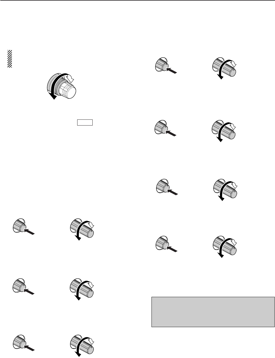
uMICROPHONE CONNECTOR [MIC]
Accepts an optional microphone.
• See p. 15-4 for appropriate microphones.
• See p. 2-10 for microphone connector information.
iMIC GAIN CONTROL [MIC] (p. 3-12)
Adjusts microphone input gain.
• The transmit audio tone in SSB, AM and FM modes can
be adjusted independently in set mode. (p. 12-5)
✔
How to set the microphone gain.
Set the [MIC] control so that the ALC meter occasionally
moves up-scale during normal voice transmission in SSB,
AM or FM mode.
oVOX SWITCH
➥Push to turn the VOX function ON and OFF dur-
ing SSB, AM and FM mode operation. (p. 6-2)
➥Push and hold for 1 sec. to enter VOX set mode.
(p. 6-2)
✔
What is the VOX function?
The VOX function (voice operated transmission) activates
transmission without pushing the transmit switch or PTT
switch when you speak into the microphone; then auto-
matically returns to receive when you stop speaking.
!0 RF POWER CONTROL [RF PWR] (p. 3-12)
Continuously varies the RF output power from min-
imum (5 W*) to maximum (200 W*).
*AM mode: 5 W to 50 W
!1 BREAK-IN SWITCH
Push to turn the break-in function ON (semi-break-in,
full-break-in) and OFF during CW mode operation.
(p. 6-3)
✔
What is the break-in function?
The break-in function switches transmit and receive with
CW keying. Full break-in (QSK) can monitor the receive
signal between CW dots and dashes.
!2 ELECTRONIC CW KEYER SPEED CONTROL
[KEY SPEED] (p. 4-4)
Adjusts the internal electronic CW keyer’s speed.
• 6 wpm (min.) to 48 wpm (max.) is the available range.
!3 MONITOR SWITCH (p. 6-4)
Monitors your transmitted IF signal.
• The CW sidetone functions regardless of
switch setting in CW mode.
• The [MONITOR] indicator above this switch lights green
while the function is activated.
!4 BREAK-IN DELAY CONTROL [DELAY] (p. 6-3)
Adjusts the transmit-to-receive switching delay time
for CW semi-break-in operations.
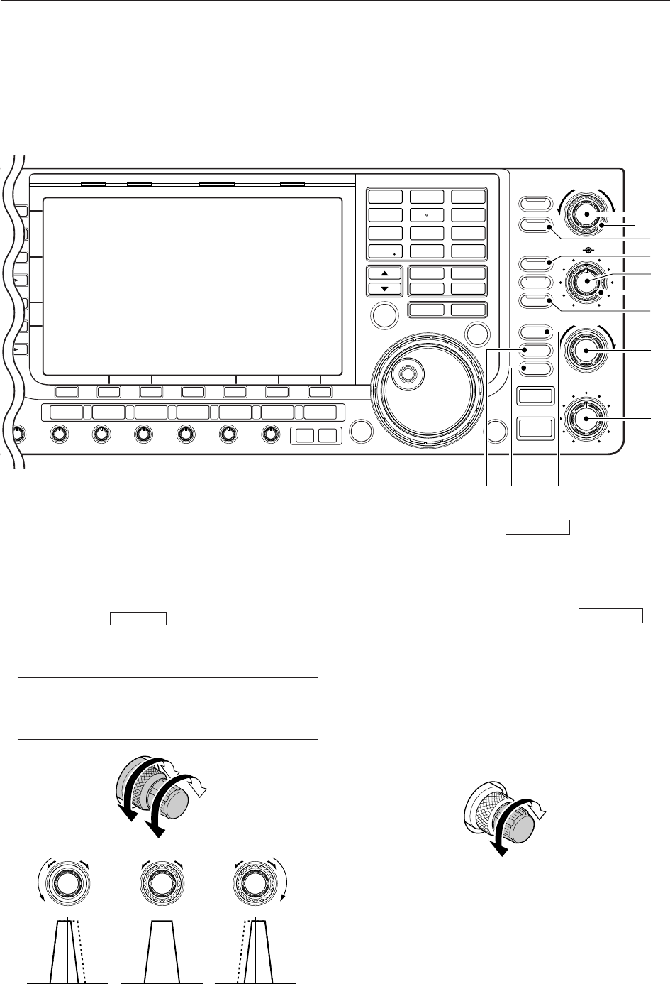
!5 AGC CONTROL [AGC] (p. 5-11)
Adjusts the continuously-variable AGC circuit time
constant.
• To use [AGC] control, push ([AGC VR] indi-
cator lights).
!6 SQUELCH CONTROL [SQL]
(outer control; p. 3-9)
Adjusts the squelch threshold level. The squelch
mutes noise output from the speaker (closed condi-
tion) when no signal is received.
• The squelch is particularly effective for FM. It is also
available in other modes.
• The 11 to 12 o’clock position is recommended for the
most effective use of the [SQL] control.
AGC VR
MONITOR
MONITOR
BK-IN
VOX
Deep
Deep
Noise squelch
Squelch
threshold
Shallow
Shallow
S-meter
squelch
Squelch is
open
Slow
Fast
Long delay for
slow speed keying
Short delay for
high speed keying
Max.
48 wpm
Min.
6 wpm
Increases
Decreases
Recommended level for
an Icom microphone
Decreases
Decreases Increases
Increases
1
PANEL DESCRIPTION
1-4
!7 NOISE REDUCTION LEVEL CONTROL [NR]
(inner control; p. 5-17)
Adjusts the DSP noise reduction level when the
noise reduction function is in use. Set for maximum
readability.
• To use this control, push .
!8 NOISE BLANKER CONTROL [NB]
(outer control; p. 5-16)
Adjust the noise blanker threshold level.
• To use this control, push .
!9 AGC VOLUME SWITCH (p. 5-11)
➥Push to toggle [AGC] control usage ON and OFF.
• Use [AGC] control to set the AGC time constant when
switched ON.
• The [AGC VR] indicator above this switch lights
green when the control is ON.
➥Turns the AGC function OFF when pushed and
held for 1 sec.
@0 USB (Universal Serial Bus) CONNECTOR [USB]
(p. 2-4)
➥Insert USB-Memory* for both reading/storing a
wide variety of the transceiver’s information and
data.
• The indicator above the connectors lights or blinks
when the transceiver reads or writes to the memory
data.
• Unmount operation is necessary before removing the
USB-Memory* (p.12-25).
➥Connects a PC keyboard for RTTY and PSK31
operations.
• USB keyboard* is supported.
*: USB-Memory or USB keyboard is not supplied by
Icom.
@1 NOISE REDUCTION SWITCH (p. 5-17)
Push to switch DSP noise reduction ON and OFF.
• The [NR] indicator above this switch lights green when
the function is activated.
@2 AF CONTROL [AF] (inner control; p. 3-9)
Varies the audio output level of the speaker or
headphones.
NR
AGC VR
NB
NR
Audio output
increases
Audio output
decreases
Deep
Shallow
Increases
Decreases
1PANEL DESCRIPTION
POWER
TUNER
TIMER
VOX
SSB CW
RTTY/PSK
AM/FM DATA AUTO
TUNE
XFC
M.SCOPE
EXIT/SET
REC
PLAY
VOICE MEMORYBRIGHTCONTRASTVOX GAINMONI GAINCOMPDRIVE ANTI VOX
BK-IN MONITOR
TRANSMIT
MIC
ELEC-KEY
PHONES
AF RF
MIC RF PWR
KEY SPEED
DELAY
F-1 F-2 F-3 F-4 F-5 F-6 F-7
LOCKTX RX SPLIT
AGC VR
NR
1
1.8 3.5
4
10 14
7
21 24
MP
M
A
GENE
50
NB
i7700
HF/50MHz TRANSCEIVER
AGC SQL NR NB
!7
!8
!9 @2 @3 @5 #2@6 @7 @8 @9 #0 #1@4@0 @1
■Front panel (continued)
1-5
@3 RF GAIN CONTROL [RF] (outer control; p. 3-9)
Adjusts the RF gain level.
While rotating the RF gain control, you may hear
noise. This comes from the DSP unit and does
not indicate a malfunction.
@4 NOISE BLANKER SWITCH (p. 5-16)
➥Switches the noise blanker ON and OFF when
pushed. The noise blanker reduces pulse-type
noise such as that generated by automobile igni-
tion systems. This function cannot be used in FM
mode, or non-pulse-type noise.
• The [NB] indicator above this switch lights green
while the function is activated.
➥Enters blanking-width set mode when pushed
and held for 1 sec.
@5 DRIVE GAIN CONTROL [DRIVE] (p. 3-13)
Adjusts the transmitter level at the driver stage. Ac-
tive in all modes (other than SSB mode with [COMP]
OFF).
@6 COMPRESSION LEVEL CONTROL [COMP]
(p. 6-5)
Adjusts the speech compression level in SSB.
@7 MONITOR GAIN CONTROL [MONI GAIN] (p. 6-4)
Adjusts the transmit IF signal monitor level.
@8 VOX GAIN CONTROL [VOX GAIN] (p. 6-2)
Adjusts the transmit/receive switching threshold
level for VOX operation.
@9 ANTI VOX CONTROL [ANTI VOX] (p. 6-2)
Adjusts the VOX sensitivity to speaker audio to pre-
vent unwanted VOX activation.
#0 LCD CONTRAST CONTROL [CONTRAST]
Adjusts the LCD contrast.
#1 LCD BRIGHTNESS CONTROL [BRIGHT]
Adjusts the LCD brightness.
#2 AUTOMATIC TUNING SWITCH [AUTOTUNE]
(p. 5-19)
Turns the automatic tuning function ON and OFF in
CW and AM modes.
NB
IMPORTANT!
When receiving a weak signal, or receiving a sig-
nal with interference, the automatic tuning func-
tion may tune the receiver to an undesired signal.
Dark
Bright
Push
Low
contrast
High
contrast
Push
‘More sensitive’
and confirm proper operation
‘Less sensitive’
and confirm
proper operation
Push
Low
sensitivity
High
sensitivity
Push
Monitor gain
decreases
Monitor gain
increases
Push
Compression
gain decreases
Compression
gain increases
Push
Decreases
Increases
Push
Sensitivity
increases
Sensitivity
decreases
1
PANEL DESCRIPTION
1-6
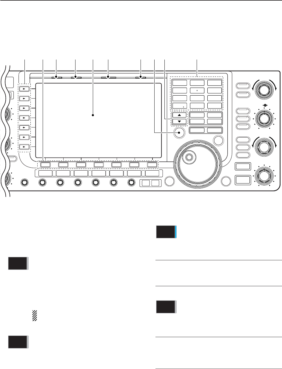
#3 MULTI-FUNCTION SWITCHES
Push to select the functions indicated in the LCD
display to the right of these switches.
• Functions vary depending on the operating condition.
MF1 (MULTI-FUNCTION 1 SWITCH)
➥Selects the antenna connector from
ANT1, ANT2, ANT3 and ANT4 when
pushed. (p. 10-2)
➥Displays antenna selection memory
when pushed and held for 1 sec.
• When the receive antenna is activated,
the antenna connected to [ANT4] is used
for receive only.
When a transverter is in use, this [ANT]
does not function and ‘TRV’ appears.
MF2 (MULTI-FUNCTION 2 SWITCH)
➥Selects RF power (Po), SWR, ALC,
COMP, VDor IDmetering during trans-
mit. (p. 3-10)
➥Switches the multi-function digital
meter ON and OFF when pushed and
held for 1 sec. (p. 3-10)
MF3 (MULTI-FUNCTION 3 SWITCH)
➥Selects one of 2 receive RF preamps
or bypasses them. (p. 5-9)
• “P. AMP1” activates 10 dB preamp.
• “P. AMP2” activates 16 dB high-gain pre-
amp.
✔
What is the preamp?
The preamp amplifies signals in the receiver front end to
improve S/N ratio and sensitivity. Select “P. AMP1” or “P.
AMP2” when receiving weak signals..
MF4 (MULTI-FUNCTION 4 SWITCH)
➥Selects 6 dB, 12 dB or 18 dB attenua-
tor when pushed. (p. 5-9)
➥Turns the attenuator function OFF
when pushed and held for 1 sec.
(p. 5-9)
✔
What is the attenuator?
The attenuator prevents a desired signal from being dis-
torted when very strong signals are near the desired fre-
quency, or when very strong electromagnetic fields, such
as from a broadcasting station, are near your location.
ATT
OFF
P.AMP
1
METER
Po
ANT
1
1PANEL DESCRIPTION
SSB CW
RTTY/PSK
AM/FM DATA AUTO
TUNE
LOCK
TS
XFC
M.SCOPE
EXIT/SET
REC
PLAY
VOICE MEMORYBRIGHTCONTRASTVOX GAINMONI GAINCOMPDRIVE ANTI VOX
MONITOR
RF
DIGI-SEL NOTCH
RIT/∂TX
CW PITCH
TWIN-PBT
D
DELAY
F-1 F-2 F-3 F-4 F-5 F-6 F-7
LOCKTX RX SPLIT
FILTER
PBT-CLR
DIGI-SEL
APF/TPF
NOTCH
RIT
CLEAR
SPEECH
1
1.8
2
3.5
3
7
4
10
5
14
6
18
7
21
8
24
MP-W MP-R
MW V/M
A/B A=B
9
28
GENE
0
50
ENT
F-INP
∂TX
NB
SPLIT
7700
NSCEIVER
NB
#3 #4 #5 #6 #8#7 #9 $0 $1 $2
■Front panel (continued)

1-7
MF5 (MULTI-FUNCTION 5 SWITCH)
➥Activates and selects fast, mid-range
or slow AGC time constant when
pushed. (p. 5-11)
• In FM mode, only “FAST” is available.
➥Enters the AGC set mode when
pushed and held for 1 sec. (p. 5-11)
AGC time constant can be set between
0.1 to 8.0 sec. (depends on mode), or
turned OFF. When AGC is “OFF,” the
S-meter does not function.
✔
What is the AGC?
The AGC controls receiver gain to produce a constant
audio output level, even when the received signal
strength varies dramatically. Select “FAST” for tuning and
then select “MID” or “SLOW” depending on the receiving
condition.
MF6 (MULTI-FUNCTION 6 SWITCH)
➥Turns the speech compressor ON and
OFF in SSB mode. (p. 6-5)
➥Switches the narrow, middle or wide
compression when pushed and held
for 1 sec.
✔
What is the speech compressor?
The speech compressor compresses the transmitter
audio input to increase the average audio output level, to
increase talk power. This function is effective for long-dis-
tance communication or when propagation conditions are
poor.
➥Turns the 1⁄4-speed tuning function ON
and OFF in SSB data, CW, RTTY and
PSK modes. (p. 3-6)
•1⁄4function sets dial rotation to 1⁄4of nor-
mal speed for fine tuning.
➥Switches between the tone encoder,
tone squelch function and no-tone op-
eration when pushed in FM mode.
(pgs. 4-33, 4-34)
➥Enters the tone set mode when
pushed and held for 1 sec. in FM
mode. (pgs. 4-33, 4-34)
MF7 (MULTI-FUNCTION 7 SWITCH)
➥Switches the voice squelch control
function ON and OFF; useful for scan-
ning. (p. 9-3)
#4 LCD FUNCTION SWITCHES –
Push to select the function indicated in the LCD dis-
play above these switches.
• Functions vary depending on the operating condition.
#5 TRANSMIT INDICATOR [TX]
Lights red while transmitting.
#6 RECEIVE INDICATOR [RX]
Lights green while receiving a signal and when the
squelch is open.
#7 LCD FUNCTION DISPLAY (p. 1-14)
Shows the operating frequency, function switch
menus, spectrum scope screen, memory list
screen, set mode settings, etc.
#8 SPLIT OPERATION INDICATOR [SPLIT]
Lights during split frequency operation.
#9 LOCK INDICATOR [LOCK] (p. 5-17)
Lights when the dial lock function is activated.
$0 TRANSMIT FREQUENCY CHECK SWITCH
[XFC] (p. 6-6)
Monitors the transmit frequency (including ∂TX fre-
quency offset) when pushed and held during split fre-
quency operation.
• While pushing this switch, the transmit frequency can be
changed with the main dial, keypad, memo pad or
/ switches.
• When the split lock function is turned ON, pushing [XFC]
cancels the dial lock function. (p. 6-7)
$1 MEMORY UP/DOWN SWITCHES /
(p. 8-2)
Push to select the desired memory channel.
• Memory channels can be selected both in VFO and
memory modes.
$2 KEYPAD
➥Pushing a key selects the operating band. (p. 3-4)
• selects the general coverage band.
➥Pushing the same key 2 or 3 times calls up other
stacked frequencies in the band. (p. 3-4)
• Icom’s triple band stacking register memorizes 3 fre-
quencies in each band.
➥After pushing , enters a frequency or
memory channel. Pushing or /
is necessary to end the entry. (pgs. 3-5,
8-2)
• e.g. to enter 14.195 MHz, push
.
F-INPENT
14 5
28 9
1.8 1
GENE •
10 4
1.8 1
F-INPENT
√
∫
F-INPENT
F-INPENT
GENE •
√
∫
√
∫
F-7F-1
VSC
OFF
TONE
OFF
1/4
ON
COMP
OFF
WIDE
AGC
MID
1
PANEL DESCRIPTION
1-8
$3 MODE SWITCHES
Selects the desired mode. (p. 3-8)
• Announces selected mode via the speech synthesizer.
(p. 12-15)
Selects USB and LSB modes alter-
nately.
Selects CW and CW-R (CW reverse)
modes alternately.
➥Switches between RTTY and PSK
mode.
➥Switches RTTY and RTTY-R (RTTY
reverse) mode when pushed and held
for 1 sec. in RTTY mode.
➥Switches PSK and PSK-R (PSK re-
verse) mode when pushed and held
for 1 sec. in PSK mode.
Selects AM and FM modes alternately.
➥Selects SSB, AM or FM data mode
(USB-D, LSB-D, AM-D, FM-D) when
pushed in SSB, AM or FM mode, re-
spectively.
➥Switches D1, D2 and D3 when
pushed and held for 1 sec.
$4 QUICK TUNING SWITCH [TS]
➥Turns the quick tuning step ON and OFF.
(p. 3-6)
• While the quick tuning indicator, “Z,” is displayed
above the frequency indication, the frequency can be
changed in programmed kHz steps.
• 0.1, 1, 5, 9, 10, 12.5, 20 and 25 kHz steps are avail-
able for each operating mode independently.
➥When the quick tuning step is OFF, push and
hold for 1 sec. to turn the 1 Hz tuning step ON
and OFF. (p. 3-7)
➥When the quick tuning step is ON, push and hold
for 1 sec. to enter quick tuning step set mode.
(p. 3-6)
$5 VFO SELECT SWITCH
Switches the selected VFO between the VFO-A and
VFO-B when pushed.
• Switches between transmit frequency and receive fre-
quency when the split frequency function is ON. (p. 6-6)
$6 MEMORY WRITE SWITCH (p. 8-3)
Stores the selected readout frequency and operat-
ing mode into the displayed memory channel when
pushed and held for 1 sec.
• This function is available both in VFO and memory
modes.
MW
A/B
DATA
AM/FM
RTTY/PSK
CW
SSB
1PANEL DESCRIPTION
SSB CW
RTTY/PSK
AM/FM DATA AUTO
TUNE
LOCK
TS
XFC
M.SCOPE
EXIT/SET
REC
PLAY
VOICE MEMORYBRIGHTCONTRASTVOX GAINMONI GAINCOMPDRIVE ANTI VOX
MONITOR
RF
DIGI-SEL NOTCH
RIT/∂TX
CW PITCH
TWIN-PBT
D
DELAY
F-1 F-2 F-3 F-4 F-5 F-6 F-7
LOCKTX RX SPLIT
FILTER
PBT-CLR
DIGI-SEL
APF/TPF
NOTCH
RIT
CLEAR
SPEECH
1
1.8
2
3.5
3
7
4
10
5
14
6
18
7
21
8
24
MP-W MP-R
MW V/M
A/B A=B
9
28
GENE
0
50
ENT
F-INP
∂TX
NB
SPLIT
7700
NSCEIVER
NB
$5 $7 $8 $9 %0 %2$6
%8 %9%7 ^0
$4 %1
%4 %5
$3
%6%3
■Front panel (continued)

1-9
$7 MEMO PAD-WRITE SWITCH (p. 8-7)
Programs the displayed readout frequency and op-
erating mode into a memo pad.
• The 5 most recent entries remain in memo pads.
• The memo pad capacity can be expanded from 5 to 10
in set mode. (p. 12-15)
$8 MEMO PAD-READ SWITCH (p. 8-7)
Each push calls up a frequency and operating mode
in a memo pad. The 5 (or 10) most recently pro-
grammed frequencies and operating modes can be
recalled, starting from the most recent.
• The memo pad capacity can be expanded from 5 to 10
in set mode. (p. 12-15)
$9 VFO/MEMORY SWITCH
➥Switches the selected readout operating mode
between the VFO and memory when pushed.
(pgs. 3-3, 8-2)
➥Transfers the memory contents to VFO when
pushed and held for 1 sec. (p. 8-4)
%0 VFO EQUALIZING SWITCH (p. 3-3)
Transfers the undisplayed VFO frequency to the
displayed VFO frequency when pushed and held for
1 sec.
%1 FILTER SWITCH (p. 5-13)
➥Selects one of 3 IF filter settings.
➥Enters the filter set screen when pushed and
held for 1 sec.
%2 AUDIO PEAK FILTER/TWIN PEAK FILTER
SWITCH
➥Push to turn the audio peak filter ON and OFF
during CW mode operation. (p. 4-6)
• “ ” appears when audio peak filter is in use.
➥Push to turn the twin peak filter ON and OFF dur-
ing RTTY mode operation. (p. 4-14)
• “ ” appears when twin peak filter is in use.
➥During CW mode operation, push and hold for
1 sec. to select the APF passband width from
320, 160 and 80 Hz. (p. 4-6)
%3 MINI SPECTRUM SCOPE SWITCH
(p. 5-4)
➥Turns the mini spectrum scope screen ON and
OFF when pushed.
• The mini spectrum scope screen can be displayed
with another screen, such as memory or set mode
screen, simultaneously.
➥Turns the spectrum scope screen ON when
pushed and held for 1 sec.
%4 VOICE MEMORY RECORD SWITCH
(p. 7-3)
➥Push to record the received signal for the preset
time period.
• After the preset time has passed, stops recording au-
tomatically.
➥Push and hold for 1 sec. to record the received
signal until the recording is canceled.
• Push this switch momentarily to stop recording.
• The memory records the latest 30 sec. of audio.
%5 VOICE MEMORY PLAYBACK SWITCH
(p. 7-4)
➥Plays back the previously recorded audio for the
preset time period when pushed.
➥Plays back all of the previously recorded audio
when pushed and held for 1 sec.
%6 EXIT/SET SWITCH
➥Push to exit, or return to the previous screen in-
dication during spectrum scope, memory, scan or
set mode screen display.
➥Displays set mode menu screen when pushed
and held for 1 sec.
%7 MAIN DIAL
Changes the displayed frequency, selects set mode
setting, etc.
%8 LOCK SWITCH [LOCK] (p. 5-17)
Push to switch the dial lock function ON and OFF.
%9 SPEECH SWITCH (p. 3-11)
➥Push to announce the S-meter indication and the
selected frequency.
➥The selected operating mode is additionally an-
nounced when pushed and held for 1 sec.
^0 SPLIT SWITCH (p. 6-6)
➥Turns the split function ON and OFF when
pushed.
➥Turns the split function ON. When pushed and
held for 1 sec. in non-FM modes, transfers the
unselected VFO’s readout frequency to the se-
lected VFO’s readout and sets the unselected
VFO to transmit VFO. (Quick split function)
• The offset frequency is shifted from the selected VFO
frequency in FM mode. (p. 12-13)
• The quick split function can be turned OFF using set
mode. (p. 12-12)
➥Turns the split function ON and shifts the unse-
lected VFO frequency after inputting an offset.
SPLIT
SPEECH
EXIT/SET
PLAY
REC
M.SCOPE
TPF
APF
APF/TPF
FILTER
A=B
V/M
MP-R
MP-W
1
PANEL DESCRIPTION
1-10
^1 PASSBAND TUNING CONTROLS [TWIN-PBT]
(p. 5-12)
Adjusts the receiver’s IF filter “passband width” via
the DSP.
• Passband width and shift frequency are displayed in the
multi-function display.
• Push and hold for 1 sec. to clear the PBT
settings.
• Adjustment range is set to half of the IF filter passband
width. 25 Hz steps and 100 Hz steps are available.
✔
What is the PBT control?
The PBT function electronically modifies the IF passband
width to reject interference. This transceiver uses the
DSP circuit for the PBT function.
^2 PBT CLEAR SWITCH (p. 5-12)
Clears the PBT settings when pushed and held for
1 sec.
• The [PBT-CLR] indicator above this switch lights when
PBT is in use.
^3 DIGITAL RF SELECTOR SWITCH
(p. 5-18)
Turns the digital RF preselector ON and OFF.
• The [DIGI-SEL] indicator lights green when the prese-
lector is in use.
^4 DIGITAL RF SELECTOR CONTROL [DIGI-SEL]
(p. 5-18)
Adjusts the digital RF selector center frequency.
• The control can be reassigned as the audio peak filter
adjustment (p. 12-16)
DIGI-SEL
PBT-CLR
PBT-CLR
Higher
frequency
Lower
frequency
PBT1
PBT2
Low cutHigh cut Center
–+
1PANEL DESCRIPTION
SSB CW
RTTY/PSK
AM/FM DATA AUTO
TUNE
LOCK
TS
XFC
M.SCOPE
EXIT/SET
REC
PLAY
VOICE MEMORYBRIGHTCONTRASTVOX GAINMONI GAINCOMPDRIVE ANTI VOX
DIGI-SEL NOTCH
RIT/∂TX
CW PITCH
TWIN-PBT
F-1 F-2 F-3 F-4 F-5 F-6 F-7
LOCKTX RX SPLIT
FILTER
PBT-CLR
DIGI-SEL
APF/TPF
NOTCH
RIT
CLEAR
SPEECH
1
1.8
2
3.5
3
7
4
10
5
14
6
18
7
21
8
24
MP-W MP-R
MW V/M
A/B A=B
9
28
GENE
0
50
ENT
F-INP
∂TX
SPLIT
&1 &0 ^9
^1
^2
^3
^4
^5
^6
^7
^8
■Front panel (continued)
1-11
^5 MANUAL NOTCH FILTER CONTROL [NOTCH]
(outer control; p. 5-18)
Varies the “valley” frequency of the manual notch fil-
ter to reject an interfering signal while the manual
notch function is ON.
• Notch filter center frequency:
SSB : –1060 Hz to 4040 Hz
CW : CW pitch freq. + 2540 Hz to CW pitch freq.
–2540 Hz
AM : –5100 Hz to 5100 Hz
^6 NOTCH SWITCH (p. 5-18)
➥Switches the notch function between auto, man-
ual and OFF in SSB and AM modes.
➥Turns the manual notch function ON and OFF
when pushed in CW, RTTY and PSK31 mode.
➥Turns the auto notch function ON and OFF when
pushed in FM mode.
• “ ” appears when manual notch is in use.
• “ ” appears when auto notch is in use.
➥Switches the manual notch characteristics from
wide, middle and narrow when pushed and held
for 1 sec.
✔
What is the notch function?
The notch function is a narrow filter that eliminates un-
wanted CW or AM carrier tones while preserving the de-
sired voice signal. The DSP circuit automatically adjusts
the filtering frequency to effectively eliminate unwanted
tones.
^7 RIT/
∂
TX CONTROL [RIT/
∂
TX] (pgs. 5-10, 6-4)
Shifts the receive and/or transmit frequency without
changing the transmit and/or receive frequency
shown on the main VFO.
• Rotate the control clockwise to increase the frequency,
or rotate the control counterclockwise to decrease the
frequency. The RIT or ∂TX functions must be ON.
• The shift frequency range is ±9.999 kHz in 1 Hz steps
(or ±9.99 kHz in 10 Hz steps).
^8 CW PITCH CONTROL [CW PITCH] (p. 4-5)
Shifts the received CW audio pitch and the CW side
tone pitch without changing the operating frequency.
^9 RIT SWITCH (p. 5-10)
➥Turns the RIT function ON and OFF when
pushed.
• Use [RIT/∂TX] control to vary the RIT frequency.
➥Adds the RIT shift frequency to the operating fre-
quency when pushed and held for 1 sec.
✔
What is the RIT function?
Receiver incremental tuning (RIT) shifts the receive fre-
quency without shifting the transmit frequency.
This is useful for fine tuning stations calling you off-fre-
quency or when you prefer to listen to slightly different-
sounding voice characteristics, etc.
&0 CLEAR SWITCH (pgs. 5-10, 6-4)
Clears the RIT/∂TX shift frequency when pushed
and held for 1 sec. or when pushed momentarily,
depending on the quick RIT/∂TX clear function set-
ting (p. 12-15).
&1
∂
TX SWITCH (p. 6-4)
➥Turns the ∂TX function ON and OFF when
pushed.
• Use [RIT/∂TX] control to vary the ∂TX frequency.
➥Adds the ∂TX shift frequency to the operating
frequency when pushed and held for 1 sec.
✔
What is the
∂
TX function?
∂TX shifts the transmit frequency without shifting the re-
ceive frequency. This is useful for simple split frequency
operation in CW, etc.
∂
TX
CLEAR
RIT
AN
MN
NOTCH
High
frequency
Low
frequency
Frequency
increases
Frequency
decreases
Higher
frequency
Lower
frequency
1
PANEL DESCRIPTION
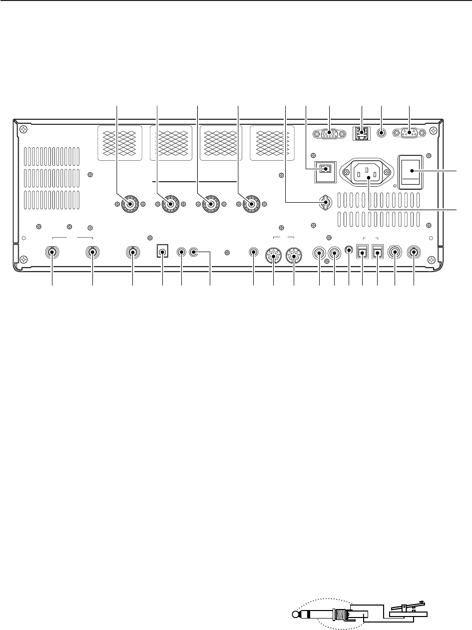
qANTENNA CONNECTOR 1 [ANT 1] (p. 2-5)
wANTENNA CONNECTOR 2 [ANT 2] (p. 2-5)
eANTENNA CONNECTOR 3 [ANT 3] (p. 2-5)
rANTENNA CONNECTOR 4 [ANT 4] (p. 2-5)
Accept a 50 antenna with a PL-259 plug connec-
tor.
tGROUND TERMINAL [GND] (p. 2-4)
Connect this terminal to a ground to prevent electri-
cal shocks, TVI, BCI and other problems.
yCIRCUIT BREAKER
Cuts off the AC input when over-current occurs.
uEXTERNAL DISPLAY TERMINAL
[EXT-DISPLAY] (p. 2-7)
Connects to an external display monitor.
• At least 800×600 pixel display is necessary.
iETHERNET CONNECTOR (p. 16-6)
Connects to a PC through a LAN (Local Area Net-
work).
oCI-V REMOTE CONTROL JACK [REMOTE]
(pgs. 2-6, 14-2)
➥Connects a PC via the optional CT-17 CI-V LEVEL
CONVERTER for external control of the transceiver.
➥Used for transceive operation with another Icom
CI-V transceiver or receiver.
!0 RS-232C TERMINAL [RS-232C] (p. 2-6)
Connects an RS-232C cable, D-sub 9-pin to con-
nect the IC-7700 to a PC.
Can be used to remotely control the IC-7700 with-
out the optional CT-17, or for RTTY/PSK31 de-
coded signal output. The [RS-232C] interface is
wired as a modem (DCE).
!1 MAIN POWER SWITCH [I/O] (p. 3-2)
Turns the internal power supply ON and OFF.
!2 AC POWER SOCKET [AC] (p. 2-5)
Connects the supplied AC power cable to an AC
line-voltage receptacle.
!3 REFERENCE SIGNAL INPUT/OUTPUT
TERMINAL [REF I/O]
Inputs/outputs a 10 MHz reference signal.
!4 STRAIGHT KEY JACK [CW KEY] (p. 2-5)
Accepts a straight key or external electronic keyer
with 1⁄4inch standard plug.
• [ELEC-KEY] on the front panel can be used for a
straight key or external electronic keyer. Deactivate the
internal electronic keyer in keyer set mode. (p. 4-12)
1-12
1PANEL DESCRIPTION
ALC
ADJ
ALCRELAY CW KEY
EXT
KEYPAD
METER
DC OUT
15V
MAX1A
REF I/O
10MHz
-
10dBm
INOUT
REMOTE RS
-
232C
EXT
-
DISPLAY
RX ANT
INOUT
S/P DIF
12
ACC
EXT
-
SP
ANT 1 ANT 2 ANT 3 ANT 4
GND
AC
15A
I
X
-
VERTER
u i o !0
!4 !3!5!6!7!8!9@0@1@2@3@4@5@6@7@8
!1
!2
t yqwer
■Rear panel
(+)
(_)
1-13
!5 S/P DIF INPUT TERMINAL [S/P DIF– IN] (p. 2-7)
!6 S/P DIF OUTPUT TERMINAL [S/P DIF– OUT]
(p. 2-7)
Connects external equipment that supports S/P DIF
input/output.
!7 ALC LEVEL ADJUSTMENT POT [ALC ADJ]
Adjusts the ALC levels.
No adjustment is required when the ALC output
level of a connected non-Icom linear amplifier is 0
to –4 V a DC.
!8 ALC INPUT JACK [ALC] (p. 2-8)
Connects to the ALC output jack of a non-Icom lin-
ear amplifier.
!9 T/R CONTROL JACK [RELAY] (p. 2-8)
Connects to ground when transmitting to control an
external unit, such as a non-Icom linear amplifier.
@0 ACCESSORY SOCKET 1 [ACC 1]
@1 ACCESSORY SOCKET 2 [ACC 2]
Enable connection of external equipment such as a
linear amplifier, an automatic antenna selector/
tuner, a TNC for data communications, etc.
• See p. 2-11 for socket information.
@2
EXTERNAL SPEAKER JACK [EXT-SP]
(p. 2-6)
Connects an external speaker (4–8 ), if desired.
@3 EXTERNAL KEYPAD JACK [EXT KEYPAD]
(p. 2-7)
Connects an external keypad for direct voice mem-
ory or electronic keyer control.
Transceiver mute control line (both transmit and re-
ceive) is also supported.
@4 METER JACK [METER] (p. 2-7)
Outputs a signal showing received signal strength,
transmit output power, VSWR, ALC, speech com-
pression, VDor IDlevel for external meter indication.
@5 DC OUTPUT JACK [DC OUT] (p. 2-7)
Outputs a regulated 14 V DC (approx.) for external
equipment. Connected in parallel with 13.8 V out-
puts of [ACC 1] and [ACC 2]. (max. 1 A in total)
@6 TRANSVERTER CONNECTOR [X-VERTER]
(p. 2-6)
External transverter input/output connector.
Activated by voltage applied to [ACC 2] pin 6, or
when the transverter function is in use. (pgs. 2-11)
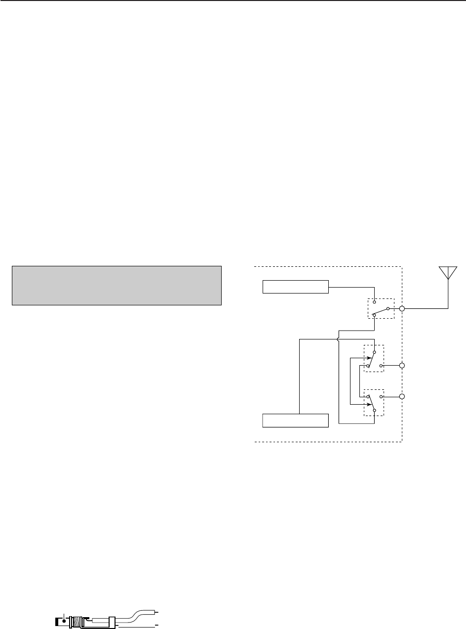
@7 RECEIVE ANTENNA IN [RX ANT– IN]
@8 RECEIVE ANTENNA OUT [RX ANT– OUT]
Located between the transmit/receive switching cir-
cuit and receiver’s RF stage.
Connects an external unit, such as preamplifier or
RF filter, using BNC connectors, if desired.
When no external unit is connected, [RX ANT– IN]
and [RX ANT– OUT] must be deactivated and
shorted by the switching relay internally. This set-
ting is available on the antenna set screen. (p. 10-5)
NOTE: T/R control voltage and current must be
lower than 16 V DC/0.5 A (or 250 V AC,
200 mA with MOSFET switching).
1
PANEL DESCRIPTION
Receiver
Transmitter
IN
[RX ANT]
OUT
Transmit/Receive
switching circuit
ANT
RX
only
+
_
_
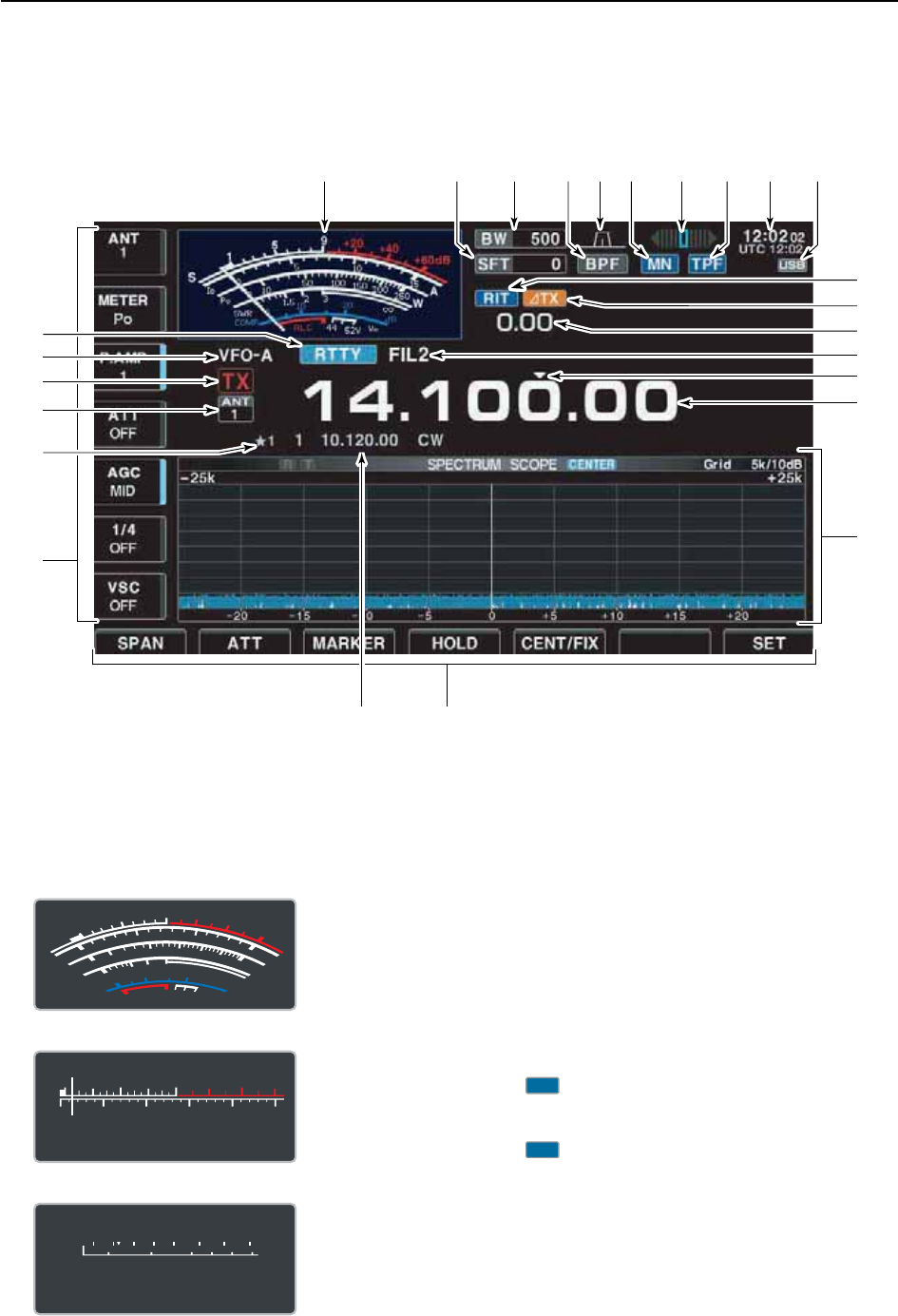
qS/RF METER (pgs. 3-10, 3-11)
Shows the signal strength while receiving. Shows
the relative output power, SWR, ALC or compres-
sion levels while transmitting.
• A total of 3 meter types are available.
wSHIFT FREQUENCY INDICATOR (p. 5-12)
Shows the shift frequency of the IF filter.
eBAND WIDTH INDICATOR (p. 5-12)
Shows the passband width of the IF filter.
rBANDPASS FILTER INDICATOR
Appears when the narrow filter (500 Hz or less) is
selected during CW, RTTY or PSK31 operation.
tPASSBAND WIDTH INDICATOR (p. 5-12)
Graphically displays the passband width for twin
PBT operation and center frequency for IF shift op-
eration.
yNOTCH INDICATOR (p. 5-18)
➥“ ” appears when the manual notch function
is in use. This function is available in SSB, CW,
RTTY, PSK and AM modes.
➥“ ” appears when the auto notch function is
in use. This function is available in SSB, AM and
FM modes.
uRTTY TUNING INDICATOR
Shows the tuning condition in RTTY mode.
AN
MN
1-14
1PANEL DESCRIPTION
qu
!1
!2
!4
!5
!6
oetwyri!0
!8
!9
@0
@2
@1
@3
@4
@5
!7
!3
■LCD display
S
Po
13579
250W200100 150500
+20 +40 +60dB
S
Po
13579
250W200100 15050
0
10
+20 +40 +60dB
• Standard meter
• Edgewise meter
• Bar meter
S
1
0
0
0
1
2
510
10
10 20
44 52V
50 100 150 200 250
15
3
1.5
ID
VD
dB
WA
Po
SWR
COMP ALC
59+20 +40 +60dB
'

1-15
1
PANEL DESCRIPTION
iAPF/TPF INDICATOR
➥“ ” appears when the audio peak filter func-
tion is in use. This function is available in CW
mode. (p. 4-6)
➥“ ” appears when the twin peak filter function
is in use. This function is available in RTTY
mode. (p. 4-14)
oCLOCK READOUT
Shows the current time. Local and UTC time can be
indicated at the same time.
!0 USB-MEMORY INDICATOR
Appears when USB-Memory is connected and
blinks while reading or writing the USB-Memory.
!1 RIT INDICATOR
Appears when RIT function is in use.
!2
∂
TX INDICATOR
Appears when ∂TX function is in use.
!3 RIT/
∂
TX SHIFT FREQUENCY INDICATOR
Shows the shift frequency for the RIT or ∂TX func-
tion.
!4 IF FILTER INDICATOR (p. 5-13)
Shows the selected IF filter number.
!5 QUICK TUNING INDICATOR (p. 3-6)
Appears when the quick tuning step function is in use.
!6 FREQUENCY READOUTS
Shows the operating frequency.
!7 MULTI-FUNCTION SCREEN
Shows the screens for the multi-function digital
meter, spectrum scope, voice recorder, memory list,
scan, memory keyer, RTTY decoder, PSK decoder,
IF filter selection or set modes, etc.
!8 LCD FUNCTION SWITCH GUIDE
Indicates the function of the LCD function switches
(–).
!9 MEMORY CHANNEL READOUTS
➥Shows the selected memory channel contents in
VFO mode.
➥Shows the VFO contents in memory mode.
@0 MULTI-FUNCTION SWITCH GUIDE
Indicates the function of the multi-function switches.
@1 SELECT MEMORY CHANNEL INDICATOR (p. 9-7)
Indicates the displayed memory channel is set as a
select memory channel.
@2 SELECT ANTENNA INDICATOR
Indicates the selected antenna.
@3 TX INDICATOR
Indicates the frequency readout for transmit.
@4 VFO/MEMORY CHANNEL INDICATOR (p. 3-3)
Indicates the VFO mode or selected memory chan-
nel number.
@5 MODE INDICATOR
Shows the selected mode.
F-7
F-1
TPF
APF
1-16
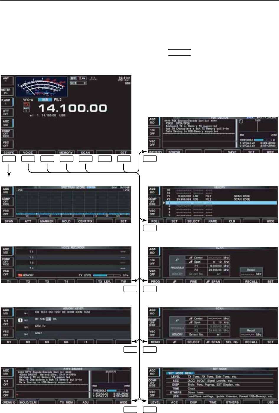
1PANEL DESCRIPTION
The following screens can be selected from the start
up screen. Choose the desired screen using the fol-
lowing chart.
Pushing several times returns to the start up
screen. See p. 12-3 for set mode arrangement.
EXIT/SET
• Spectrum scope screen (p. 5-2)
• Voice recorder screen (p. 7-3)
• RTTY decoder screen (RTTY mode; p. 4-13)
• Memory keyer screen (CW mode; p. 4-8)
• Memory list screen (p. 8-5)
• PSK31 decoder screen (PSK mode; p. 4-21)
• Scan screen (VFO mode; p. 9-4)
• Scan screen (Memory mode; p. 9-6)
• Set mode menu screen (p. 12-2)
F-1 F-2 F-3 F-3
F-4
F-5F-2
F-5F-3
F-7F-3
F-4 F-5 F-6 F-7
■Screen menu arrangement

2-1
INSTALLATION AND CONNECTIONS Section 2
■Unpacking ……………………………………………………………… 2-2
■Main dial attachment …………………………………………………… 2-2
■Rack mounting handle detachment …………………………………… 2-3
■Selecting a location …………………………………………………… 2-3
■Grounding ……………………………………………………………… 2-4
■Antenna connection …………………………………………………… 2-4
■USB-Memory connection ……………………………………………… 2-4
■Required connections ………………………………………………… 2-5
DFront panel …………………………………………………………… 2-5
DRear panel …………………………………………………………… 2-5
■Advanced connections ………………………………………………… 2-6
DFront panel …………………………………………………………… 2-6
DRear panel—1 ……………………………………………………… 2-6
DRear panel—2 ……………………………………………………… 2-7
■Linear amplifier connections …………………………………………… 2-8
DConnecting the IC-PW1/EURO …………………………………… 2-8
DConnecting a non-Icom linear amplifier …………………………… 2-8
■Transverter jack information …………………………………………… 2-9
■FSK and AFSK (SSTV) connections ………………………………… 2-9
■Microphone connector information ………………………………… 2-10
■Microphones (options) ………………………………………………… 2-10
DSM-20 ……………………………………………………………… 2-10
DHM-36 ……………………………………………………………… 2-10
■Accessory connector information …………………………………… 2-11
CAUTION!: The transceiver weighs approx. 24 kg (53 lb).
Always have two people available to carry, lift or
turn over the transceiver.
2-2
■Unpacking
After unpacking, immediately report any damage to the
delivering carrier or dealer. Keep the shipping cartons.
For a description and a diagram of accessory equip-
ment included with the IC-7700, see ‘Supplied acces-
sories’ on p. iii of this manual.
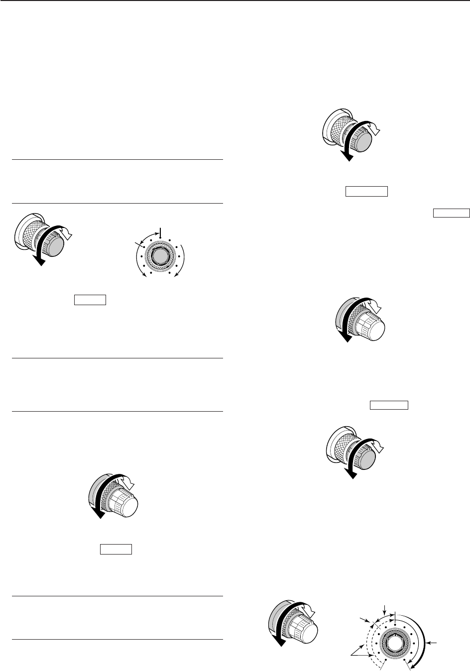
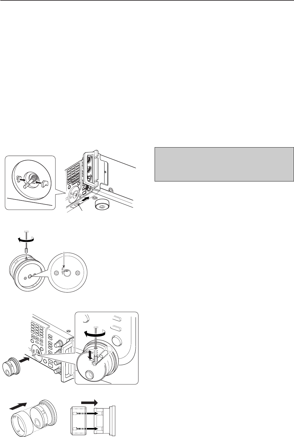
■Main dial attachment
The main dial is shipped unattached to the transceiver
to prevent possible damage to the dial shaft or rotary
encoder during shipping. Please attach the dial as de-
scribed below.
qSlide the dial brake adjustment to the right position
(Fig. 1).
• The dial brakes move inward as shown.
wInsert the main dial set-screw into the screw hole of
the main dial, then tighten the screw until the screw
extends into the shaft hole out slightly using sup-
plied hexagonal wrench (2 mm) (Fig. 2).
• Be careful that the screw does not extend out more than
1 mm (1/32 in).
eAttach the main dial as illustrated (Fig. 3).
• Be careful to match the correct orientation of the flat face
of the shaft and the screw hole of the dial knob.
rTighten the screw using supplied hexagonal wrench
as illustrated (Fig. 3).
tInstall the rubber cover of the main dial (Fig. 4).
Then adjust the main dial brake as desired.
• Be careful to match the correct position of the convex
part of the cover and the concavo part of the dial knob.
2INSTALLATION AND CONNECTIONS
Dial brake adjustment
Fig. 1
q
Shorter than
1 mm (1/32 in)
Fig. 2
w
Fig. 3
er
R
CAUTION!: NEVER hold any controller
knob(s), such as the main dial, when carrying or lift-
ing the transceiver. This will damage the dial shaft or
rotary encoder.
Fig. 4 Side view
t
2-3
2
INSTALLATION AND CONNECTIONS
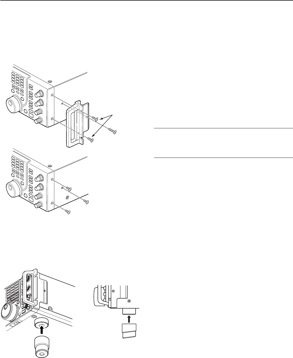
■Rack mounting handle detachment
The rack mounting handles are supplied attached to
the transceiver to stabilize the transceiver in the shock
absorber material in the box. If you want to remove
them, use the supplied screws as described below.
qRemove the six screws from the rack mounting han-
dles on both side and remove the rack mounting
handles.
wTighten the supplied six screws (PH M4×8) on both
sides of the front panel and side panel.
✔
When re-packing and shipping the transceiver:
Attach the rack mounting handles using original screws
when re-packing and shipping the transceiver at any
time.
■Selecting a location
Select a location for the transceiver that allows ade-
quate air circulation, free from extreme heat, cold, or
vibrations, and away from TV sets, TV antenna ele-
ments, radios and other electromagnetic sources.
The base of the transceiver has an adjustable feet for
desktop use. Set the feet to one of two angles de-
pending on your operating preference.
q
w
PH: Pan head
FH: Flat head
FH M4×15 mm
FH M4×9 mm
PH M4 × 8 mm
2-4
2INSTALLATION AND CONNECTIONS
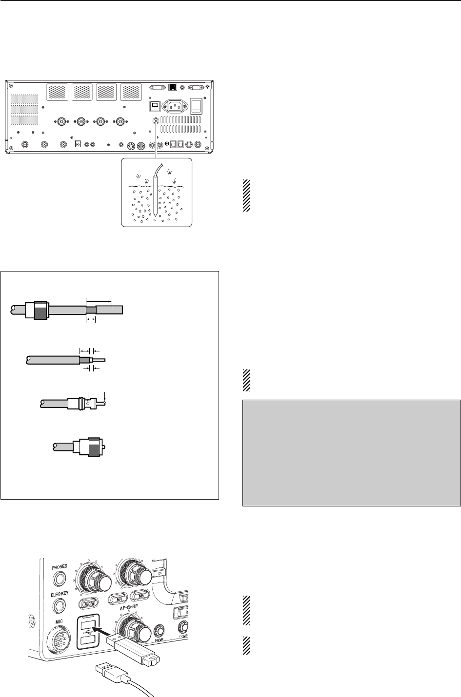
■Grounding
To prevent electrical shock, television interference
(TVI), broadcast interference (BCI) and other prob-
lems, ground the transceiver through the GROUND
terminal on the rear panel.
For best results, connect a heavy gauge wire or strap
to a long earth-sunk copper rod. Make the distance be-
tween the [GND] terminal and ground as short as pos-
sible.
RWARNING: NEVER connect the [GND]
terminal to a gas or electric pipe, since the connec-
tion could cause an explosion or electric shock.
■Antenna connection
For radio communications, the antenna is of critical im-
portance, along with output power and receiver sensi-
tivity. Select antenna(s), such as a well-matched 50
antenna, and feedline. We recommend 1.5:1 or better
of Voltage Standing Wave Ratio (VSWR) for your de-
sired band. Of course, the transmission line should be
a coaxial cable.
When using 1 antenna, use the [ANT1] connector.
CAUTION: Protect your transceiver from lightning
by using a lightning arrestor.
■USB-Memory connection (USB-Memory: Not supplied by Icom)
Connect the USB-Memory* to the USB connector.
• Unmount operation is necessary before removing the USB-
Memory* (p.12-25).
Make sure to connect the USB-Memory correctly.
NEVER connect or remove the USB-Memory when
the read/write indicator lights or blinks.
A USB keyboard* or USB hub* can also be con-
nected to the USB connector.
*: USB-Memory, USB keyboard or USB hub is not supplied
by Icom.
Antenna SWR
Each antenna is tuned for a specified frequency
range and SWR may be increased out-of-range.
When the SWR is higher than approx. 2.0:1, the
transceiver’s power drops to protect the final transis-
tors. In this case, an antenna tuner is useful to match
the transceiver and antenna. Low SWR allows full
power for transmitting. The IC-7700 has an SWR
meter to monitor the antenna SWR continuously.
PL-259 CONNECTOR INSTALLATION EXAMPLE
30 mm §9⁄8in 10 mm §3⁄8in 1–2 mm §1⁄16 in
30 mm
10 mm (soft solder)
10 mm
1–2 mm
solder solder
Soft
solder
Coupling ring
Slide the coupling ring
down. Strip the cable
jacket and in the braid.
Slide the connector
body on and solder it.
Screw the coupling
ring onto the
connector body.
Strip the cable as
shown at left. Tin the
center conductor.
q
w
e
r
or
2-5
2
INSTALLATION AND CONNECTIONS
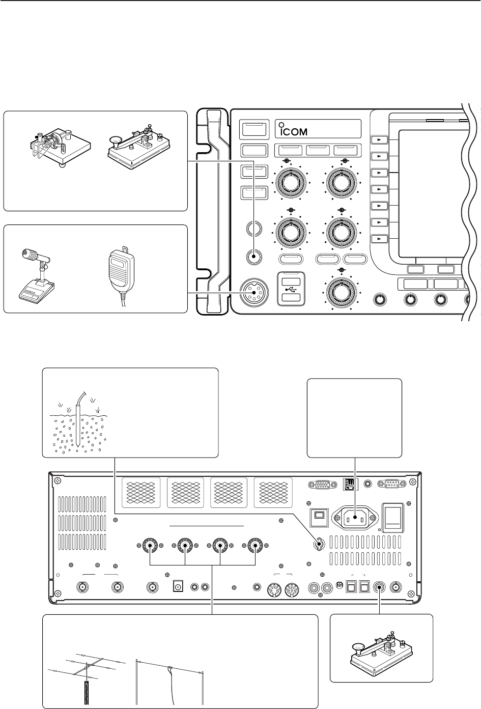
■Required connections
D
Front panel
POWER
TUNER
TIMER
VOX
SSB CW
RTTY/PS
VOX GAINMONI GAINCOMPDRIVE
BK-IN MONITOR
TRANSMIT
MIC
ELEC-KEY
PHONES
AF RF
MIC RF PWR
KEY SPEED
DELAY
F-1 F-2 F-3
TX RX
AGC VR
NR NB
i7700
HF/50MHz TRANSCEIVER
AGC SQL NR NB
Microphones (p. 2-10)
CW key
A straight or bug key can be used when
the internal electronic keyer is turned
OFF in keyer set mode. (p. 4-12)
Optional
SM-20
Optional
HM-36
D
Rear panel
ALC
ADJ
ALCRELAY CW KEY
EXT
KEYPAD
METER
DC OUT
15V
MAX1A
REF I/O
10MHz
-
10dBm
INOU T
REMOTE RS
-
232C
EXT
-
DISPLAY
RX ANT
INOUT
S/P DIF
12
ACC
EXT
-
SP
ANT 1 ANT 2 ANT 3 ANT 4
GND
AC
15A
I
X
-
VERTER
Antenna 1, 2, 3, 4 (p. 2-4) Straight key
Ground
(p. 2-4)
Use the heaviest gauge
wire or strap available and
make the connection as
short as possible.
Grounding prevents elec-
trical shocks, TVI and
other problems.
AC outlet
R WARNING:
Use the supplied
AC power cable
only.
NOTE: Attach the sup-
plied antenna connec-
tor cap when no anten-
na or external equip-
ment is connected.
[Example]: ANT1 for 1.8–18 MHz bands, ANT 2 for 21–28 MHz bands
ANT3 for 50 MHz band, ANT 4 for receive antenna.
2-6
2INSTALLATION AND CONNECTIONS
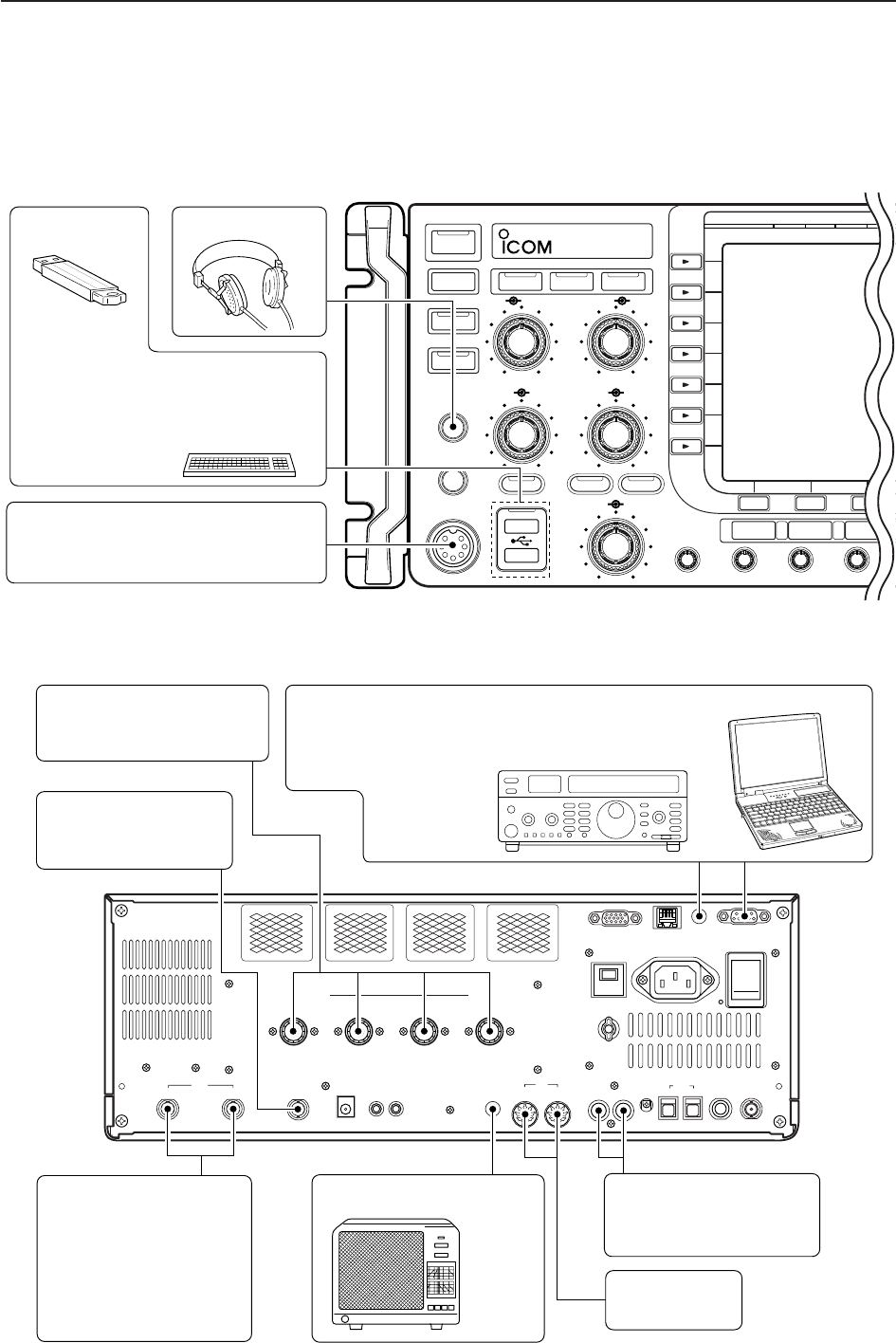
■Advanced connections
D
Front panel
ALC
ADJ
ALCRELAY CW KEY
EXT
KEYPAD
METER
DC OUT
15V
MAX1A
REF I/O
10MHz
-
10dBm
INOU T
REMOTE RS
-
232C
EXT
-
DISPLAY
RX ANT
INOUT
S/P DIF
12
ACC
EXT
-
SP
ANT 1 ANT 2 ANT 3 ANT 4
GND
AC
15A
I
X
-
VERTER
RX ANT IN/OUT
Connects an external
preamp or lowpass filter.
RX ANT IN/OUT must be
activated in the antenna
set screen (p.10-5).
ACC sockets
(pgs. 2-9, 2-11)
Antenna 1, 2, 3, 4 (p. 2-8)
Connects a linear amplifier,
antenna selector, etc.
[X-VERTER]
Connects a transverter
for V/UHF band use.
[RELAY], [ALC] (p. 2-8)
Used for connecting a
non-Icom linear amplifier.
External speaker (p. 15-4)
SP-20
(option)
[REMOTE], [RS-232C] (p. 14-2)
Used for computer control and transceive operation.
The optional CT-17 is required when connecting a
PC to [REMOTE].
POWER
TUNER
TIMER
VOX
SSB CW
RTTY/PSK
VOX GAINMONI GAINCOMPDRIVE
BK-IN MONITOR
TRANSMIT
MIC
ELEC-KEY
PHONES
AF RF
MIC RF PWR
KEY SPEED
DELAY
F-1 F-2 F-3
TX RX
AGC VR
NR NB
i7700
HF/50MHz TRANSCEIVER
AGC SQL NR NB
MIC
Headphones
USB-Memory
The AFSK modulation signal can also
be input to [MIC].
Keyboard
Connects an USB type PC key-
board directly for RTTY/PSK31 op-
eration, as well as other text edit op-
erations.
D
Rear panel— 1
2-7
2
INSTALLATION AND CONNECTIONS
D
Rear panel— 2
ALC
ADJ
ALCRELAY CW KEY
EXT
KEYPAD
METER
DC OUT
15V
MAX1A
REF I/O
10MHz
-
10dBm
INOU T
REMOTE RS
-
232C
EXT
-
DISPLAY
RX ANT
INOUT
S/P DIF
12
ACC
EXT
-
SP
ANT 1 ANT 2 ANT 3 ANT 4
GND
AC
15A
I
X
-
VERTER
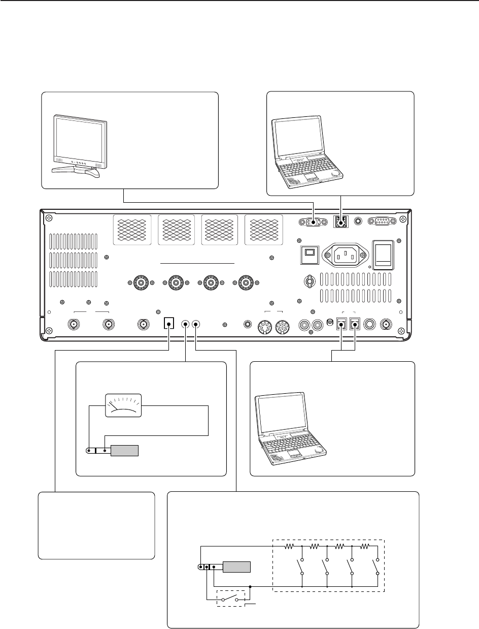
External Display
Connects a PC-style
monitor display (at least
800×600 resolution).
Video output signal can
be turned ON and OFF
in set mode (p. 12-11)
[DC OUT]
Outputs regulated 14 V
(approx.) DC for external
equipment power supply.
(max. 1 A capacity)
External keypad
Connects an external keypad for direct voice memory
and memory keyer controls.
Connects a PC for
audio signal data
(48 kHz, 16-bit)
input/output.
[S/P DIF IN/OUT]
Connects a PC
via a LAN for the
CPU firmware
update.
Ethernet connector (p. 16-6)
1.5 kΩ
±5%
1.5 kΩ
±5%
2.2 kΩ
±5%
4.7 kΩ
±5%
S1
(T1/M1)
S2
(T2/M2)
S3
(T3/M3)
S4
(T4/M4)
EXTERNAL KEYPAD
3.5 (d) mm; 1⁄8″ plug
Mute switch: Mutes both transmission and
reception when switched ON during trans-
ceive operation, etc.
[METER]
Connects an external meter, etc.
3.5 (d) mm; 1⁄8″ plug
D
Connecting a non-Icom linear amplifier RWARNING:
Set the transceiver output power and linear ampli-
fier ALC output level after referring to the linear am-
plifier instruction manual.
The ALC input level must be in the range 0 V to
–4 V. The transceiver does not accept positive volt-
age. Non-matched ALC and RF power settings
could overheat or damage the linear amplifier.
The maximum signal level of [RELAY] jack is
16 V/0.5 A DC with initial setting, and 250 V/200 mA
with “MOSFET” setting (see p. 12-8 for details). Use
an external relay unit if your non-Icom linear ampli-
fier requires control voltage and/or current greater
than specified.
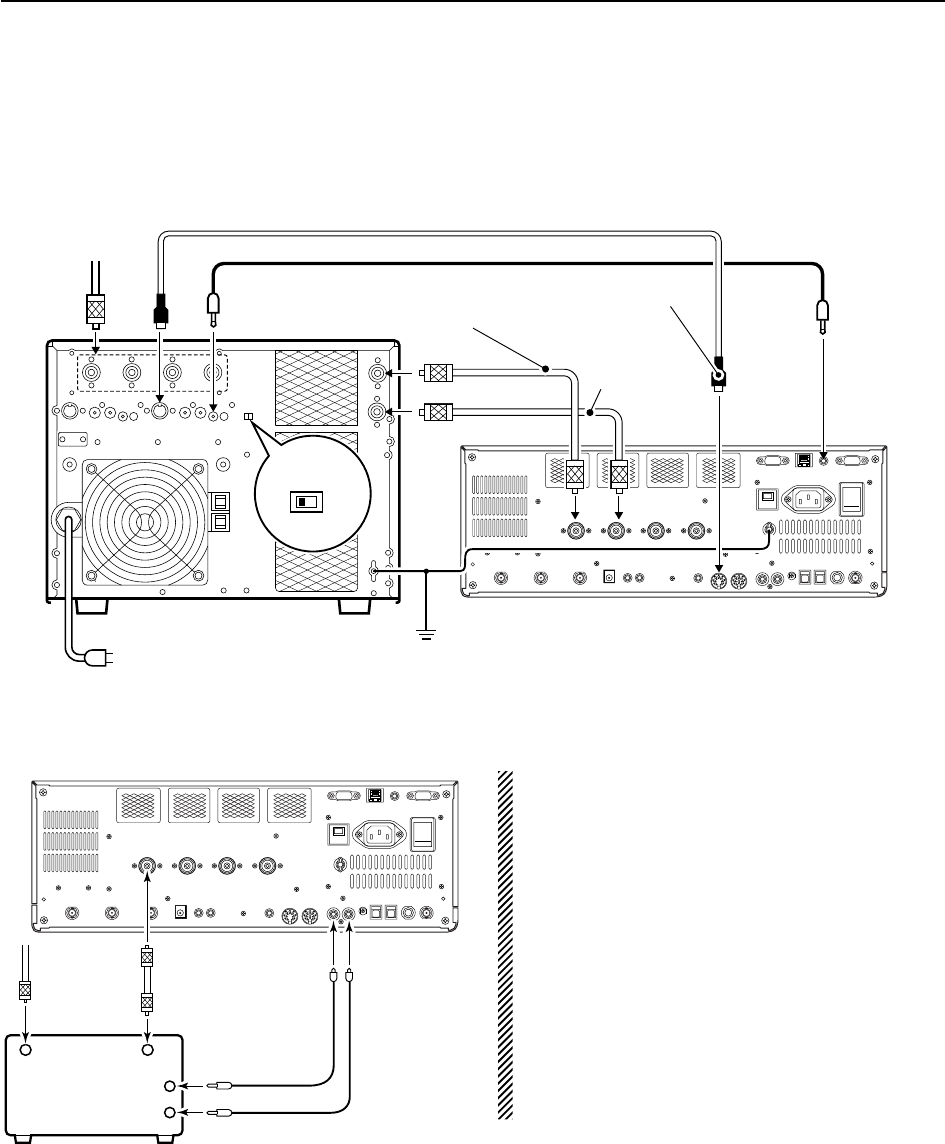
■Linear amplifier connections
D
Connecting the IC-PW1/EURO
2-8
2INSTALLATION AND CONNECTIONS
RF OUTPUT RF INPUT
SEND
ALC
50 1
coaxial cable
TransceiverANT1
ALC
RELAY
To an
antenna
Non-Icom linear amplifier
To an
antenna
ACC-1
ANT
ANT2
ANT1
ACC 2
INPUT1
INPUT2
REMOTE
EXCITER
11&2
GND
GND
IC-PW1/EURO
AC outlet
(Non-European versions: 100–120/220–240 V
European version : 230 V)
Ground
Transceiver
REMOTE
Remote control cable (supplied with the IC-PW1/EURO)
ACC cable (supplied with the IC-PW1/EURO)
Be sure to connect the cable
to the 7-pin ACC 2 jack.
Coaxial cable
(supplied with the
IC-PW1/EURO)
Coaxial cable*
*Optional
Connect
[INPUT2]
if necessary
2-9
2
INSTALLATION AND CONNECTIONS
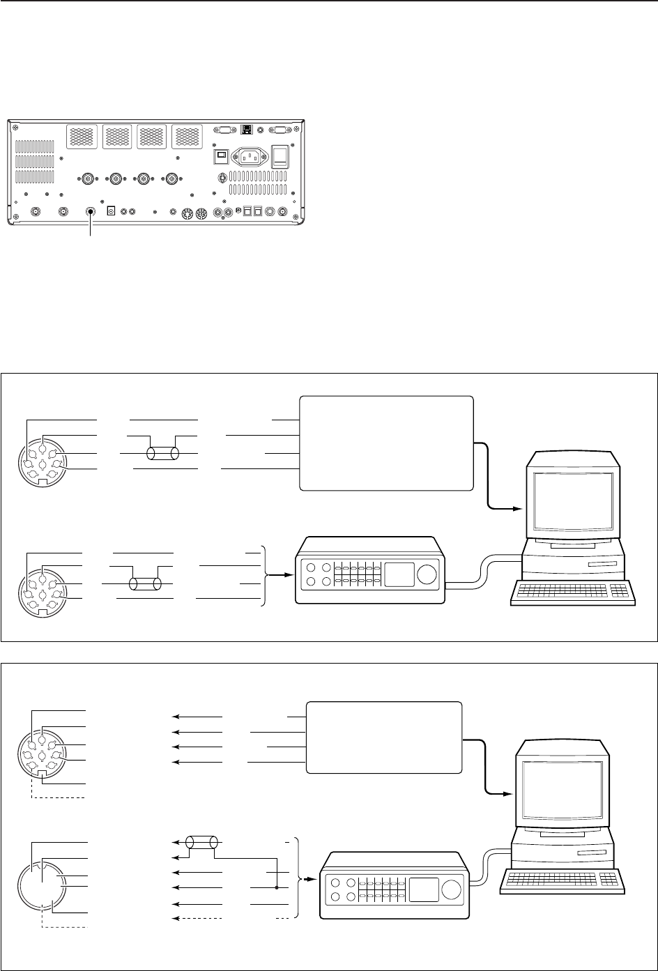
■Transverter jack information
When 2 to 13.8 V is applied to pin 6 of [ACC 2], the [X-
VERTER] connector is activated for transverter oper-
ation and the antenna connectors do not receive or
transmit any signals.
While receiving, [X-VERTER] connector can be acti-
vated as an input terminal from an external transverter.
While transmitting, the [X-VERTER] connector outputs
signals of the displayed frequency at –20 dBm (22 mV)
as signals for the external transverter.
■FSK and AFSK (SSTV) connections
To connect a TNC or scan converter, etc., refer to the
diagram below.
Connect to serial port, parallel
port, speaker jack, microphone
jack and line IN/OUT jack, etc.
See the instruction manual of
the application for details.
D AFSK operation
• When connecting to [ACC 1]
• When connecting to [MIC]
• When using a PC application
• When using a TNC
PC
RS-232C
TNC or scan converter
PTT
Audio output
AF input
GND
AFSK output
AF input
GND
PTT*
SQL input†
*When using the VOX function, no need to connect. Refer to the instruction
manual of the external equipment (TNC, etc.).
†When connecting the squelch line, consult the necessary manual (TNC, etc.).
q
w
ert
y
u
i
1
2
3
45
67
8
z
z
x
x
c
c
v
v*
z
x
c
v
z
x
c
v
b
b
n†
n†
b
n†
Rear panel view
Rear panel view
PC
RS-232C
TNC or scan converter
Connect to serial port, parallel
port, speaker jack, microphone
jack and line IN/OUT jack, etc.
See the instruction manual of the
application for details.
DFSK operation— when connecting to [ACC 1]
• When using a PC application
• When using a TNC
1
2
3
45
67
8
Rear panel view
Rear panel view
RTTY
GND
AF
SEND
RTTY
GND
AF
SEND
RTTY OUTPUT
GND
AUDIO INPUT
PTT
RTTY OUTPUT
GND
AUDIO INPUT
PTT
1
2
3
45
67
8
Transverter connector
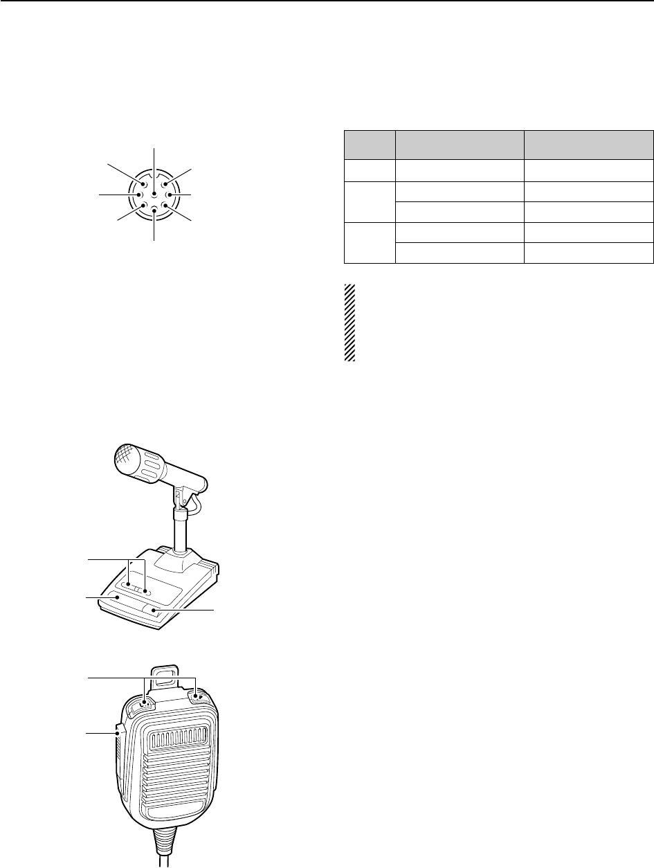
■Microphone connector information
(Front panel view)
CAUTION: DO NOT short pin 2 to ground as this
can damage the internal 8 V regulator.
NOTE: DC voltage is applied to pin 1 for micro-
phone operation. Use caution when using a non-
Icom microphone.
■Microphones (options)
qUP/DOWN SWITCHES [UP]/[DN]
Change the selected readout frequency or memory
channel.
• Continuous pushing changes the frequency or memory
channel number continuously.
• While pushing [XFC], the transmit readout frequency can
be controlled while in split frequency operation.
• The [UP]/[DN] switch can simulate a key paddle. Preset
in the keyer set mode. (p. 4-12)
wPTT SWITCH
Push and hold to transmit; release to receive.
ePTT LOCK SWITCH (available for SM-20 only)
Push to toggle between transmit and receive.
2-10
2INSTALLATION AND CONNECTIONS
[MIC] FUNCTION DESCRIPTION
Pin No.
w+8 V DC output Max. 10 mA
e
Frequency up Ground
Frequency down Ground through 470
rSquelch open “Low” level
Squelch closed “High” level
y GND (PTT ground)
t PTT
r Squelch switch
q Microphone input
w +8 V DC output
e Frequency up/down
u GND
(Microphone ground)
i AF output (varies with [AF])
D SM-20
D HM-36
q
w
q
w
e
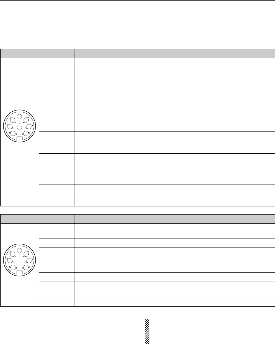
2-11
2
INSTALLATION AND CONNECTIONS
■Accessory connector information
ACC 2
PIN No.
NAME DESCRIPTION SPECIFICATIONS
ACC 1
PIN No.
NAME DESCRIPTION SPECIFICATIONS
NOTE: If the CW side tone level limit or beep level
limit is in use, the CW side tone or beep tone de-
creases from the fixed level when the [AF] control is
rotated above a specified level. (p. 12-6)
1
2
3
45
67
8
“High” level : More than 2.4 V
1 RTTY Controls RTTY keying “Low” level : Less than 0.6 V
Output current : Less than 2 mA
2 GND Connects to ground. Connected in parallel with ACC 2 pin 2.
Input/output pin. Ground level : –0.5 V to 0.8 V
3 SEND Goes to ground when transmitting. Output current : Less than 20 mA
When grounded, transmits. Input current (Tx) : Less than 200 mA
Connected in parallel with ACC 2 pin 3.
4 MOD Modulator input. Input impedance : 10 k
Connects to a modulator. Input level : Approx. 100 mV rms
AF detector output. Output impedance : 4.7 k
5 AF Fixed, regardless of [AF] position Output level : 100–300 mV rms
in default settings. (see notes below)
6 SQLS Squelch output. SQL open : Less than 0.3 V/5 mA
Goes to ground when squelch opens.
SQL closed : More than 6.0 V/100 μA
7 13.8 V 13.8 V output when power is ON. Output current : Max. 1 A
Connected in parallel with ACC 2 pin 7.
Control voltage : –4 V to 0 V
8 ALC ALC voltage input. Input impedance : More than 10 k
Connected in parallel with ACC 2 pin 5.
1 8 V Regulated 8 V output. Output voltage : 8 V ±0.3 V
Output current : Less than 10 mA
2 GND Same as ACC 1 pin 2.
3 SEND Same as ACC 1 pin 3.
4 BAND Band voltage output. Output voltage : 0 to 8.0 V
(Varies with amateur band)
5 ALC Same as ACC 1 pin 8.
6TRV
Activates [X-VERTER] input/output Input impedance : More than 10 k
when “HIGH” voltage is applied. Input voltage : 2 to 13.8 V
7
13.8 V
Same as ACC 1 pin 7.
1
2
3
45
67

3-1
BASIC OPERATIONS Section 3
■When first applying power (CPU resetting) ………………………… 3-2
■Initial settings …………………………………………………………… 3-2
■Selecting VFO/memory mode ………………………………………… 3-3
■VFO selection …………………………………………………………… 3-3
DSelecting VFO-A/VFO-B …………………………………………… 3-3
DVFO equalization …………………………………………………… 3-3
■Selecting an operating band …………………………………………… 3-4
DUsing the band stacking registers ………………………………… 3-4
■Frequency setting ……………………………………………………… 3-5
DTuning with the main dial …………………………………………… 3-5
DDirect frequency entry with the keypad …………………………… 3-5
DQuick tuning step …………………………………………………… 3-6
DSelecting “kHz” step ………………………………………………… 3-6
D1⁄4tuning step function ……………………………………………… 3-6
DSelecting 1 Hz step ………………………………………………… 3-7
DAuto tuning step function …………………………………………… 3-7
DBand edge warning beep …………………………………………… 3-7
■Operating mode selection ……………………………………………… 3-8
■Volume setting ………………………………………………………… 3-9
■RF gain adjustment …………………………………………………… 3-9
■Squelch level adjustment ……………………………………………… 3-9
■Meter indication selection …………………………………………… 3-10
DMulti-function digital meter ………………………………………… 3-10
DMeter type selection ……………………………………………… 3-11
■Voice synthesizer operation ………………………………………… 3-11
■Basic transmit operation ……………………………………………… 3-12
DTransmitting ………………………………………………………… 3-12
DMicrophone gain adjustment ……………………………………… 3-12
DDrive gain adjustment ……………………………………………… 3-13
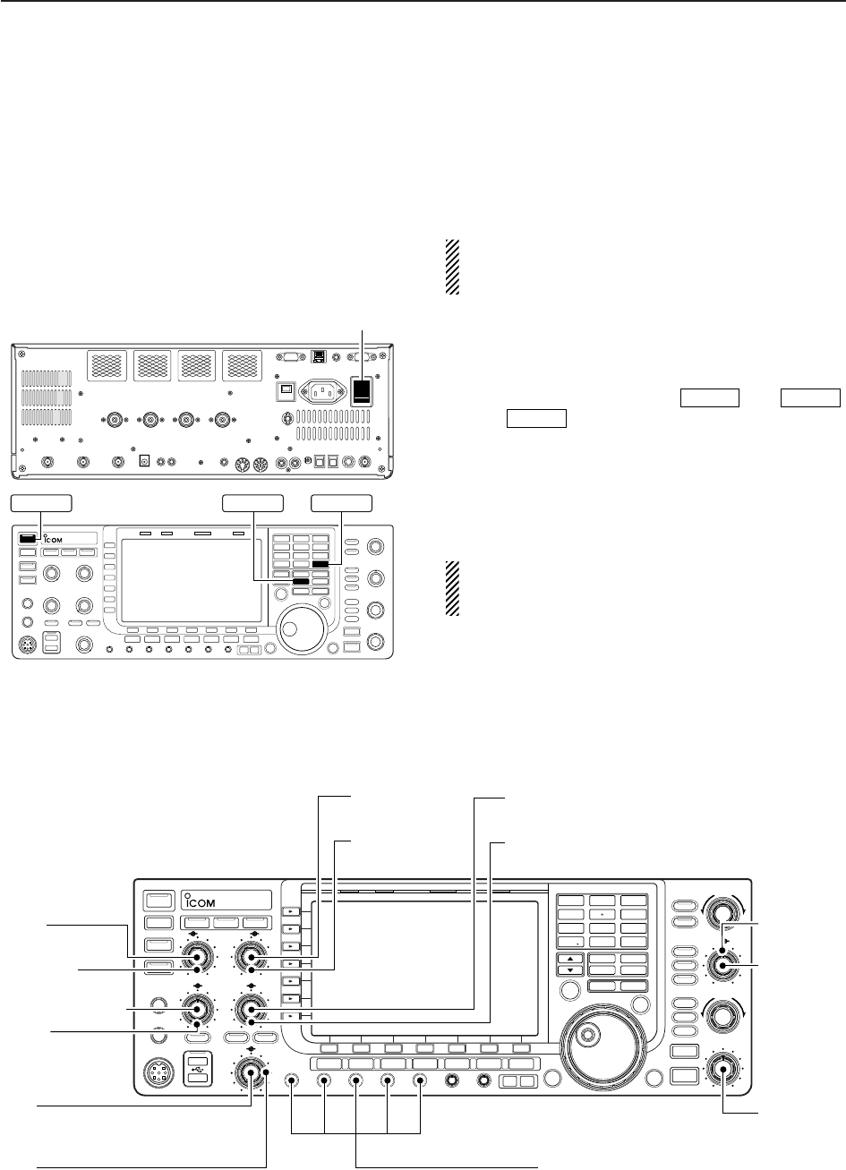
3-2
■When first applying power (CPU resetting)
Before first applying power, make sure all connections
required for your system are complete by referring to
Section 2. Then, reset the transceiver using the follow-
ing procedure.
Resetting CLEARS all programmed contents in
memory channels and returns programmed values
in set mode to default values.
qTurn the main power ON with [I/O] on the rear
panel.
• The transceiver power is still OFF and the power indi-
cator lights orange.
wWhile pushing and holding and ,
push to turn power ON.
• The CPU is reset.
• The CPU start-up takes approx. 5 sec.
• The transceiver displays its initial VFO frequencies
when resetting is complete.
eChange the set mode settings after resetting, if de-
sired.
In cooler temperatures, the LCD may appear dark
and unstable after turning power ON. This is normal
and does not indicate any equipment malfunction.
POWER
MW
F-INPENT
3BASIC OPERATIONS
[I/O]
MW F-INP ENT
POWER
POWER
TUNER
TIMER
VOX
SSB CW
RTTY/PSK
AM/FM DATA AUTO
TUNE
LOCK
TS
XFC
M.SCOPE
EXIT/SET
REC
PLAY
VOICE MEMORYBRIGHTCONTRASTVOX GAINMONI GAINCOMPDRIVE ANTI VOX
BK-IN MONITOR
TRANSMIT
MIC
ELEC-KEY
PHONES
AF RF
MIC RF PWR
DIGI-SEL NOTCH
RIT/∂TX
CW PITCH
TWIN-PBT
KEY SPEED
DELAY
F-1 F-2 F-3 F-4 F-5 F-6 F-7
LOCKTX RX SPLIT
AGC VR
NR
FILTER
PBT-CLR
DIGI-SEL
APF/TPF
NOTCH
RIT
CLEAR
SPEECH
1
1.8
2
3.5
3
7
4
10
5
14
6
18
7
21
8
24
MP-W MP-R
MW V/M
A/B A=B
9
28
GENE
0
50
ENT
F-INP
∂TX
NB
SPLIT
i7700
HF/50MHz TRANSCEIVER
AGC SQL NR NB
[RF PWR]
: Max. clockwise
[MIC]
: 10–12 o’clock
[SQL]
: Max. counter-
clockwise
[AGC]: 12 o’clock
[DEGI-SEL]
: 12 o’clock
[NOTCH]
: 12 o’clock
[NB]
: Max. counter clockwise
[AF]
: Max. counter-
clockwise
[DRIVE], [COMP], [MONI GAIN],
[VOX GAIN], [ANTI VOX]
: 12 o’clock
[RF]
: Max. clockwise
[DELAY]
: Max. clockwise
[KEY SPEED]
: 10–12 o’clock
[CW PITCH]
: 12 o’clock
[NR]
: Max. counter clockwise
■Initial settings
After resetting the transceiver, set controls as shown
in the figure below.
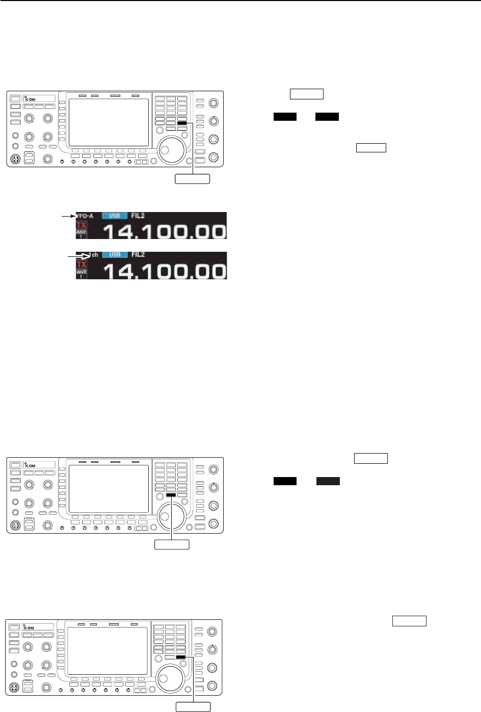
■VFO selection
VFO is an abbreviation of Variable Frequency Oscilla-
tor, and is commonly referred to as a main tuning func-
tion.
The main dial is often called the “VFO knob.”
D
Selecting VFO-A/VFO-B
➥In VFO mode, push to toggle VFO-A and
VFO-B.
• “ ” or “ ” appears when VFO-A or VFO-B is
selected, respectively
D
VFO equalization
➥In VFO mode, push and hold for 1 sec. to
set the undisplayed VFO frequency and mode to
those of the displayed VFO.
• Three beeps sound when the VFO equalization is com-
pleted.
A=B
VFO-BVFO-A
A/B
3-3
3
BASIC OPERATIONS
■Selecting VFO/memory mode
➥Push to switch between VFO and memory
modes.
• “ ” or “ ” appears when in VFO mode, or the
selected memory channel number appears when in
memory mode.
• Pushing and holding for 1 sec. transfers the
contents of the selected memory channel to VFO.
(p. 8-4)
V/M
VFO-BVFO-A
V/M
V/M
“VFO” indicator
Memory channel
number
A/B
A=B
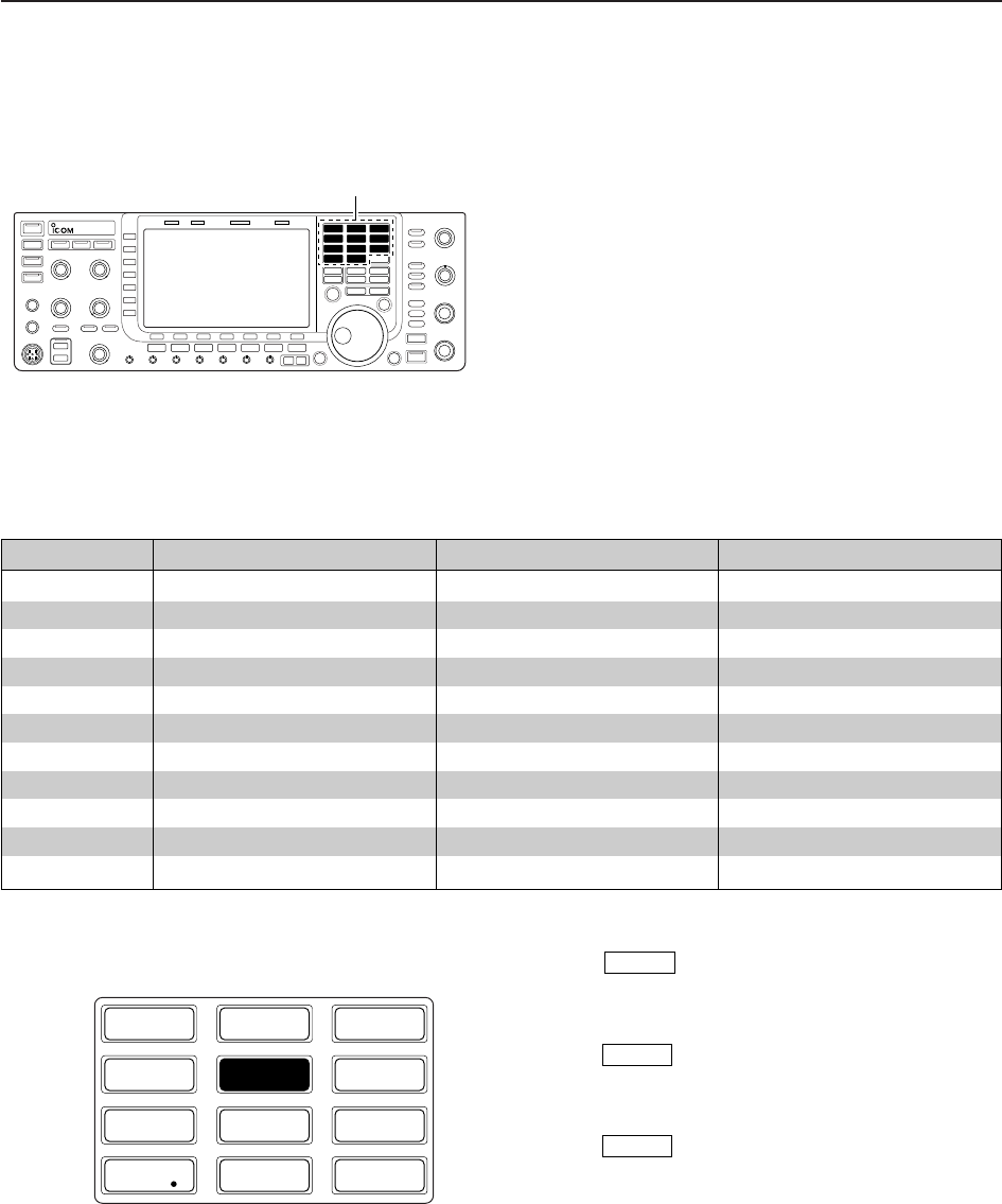
3-4
■Selecting an operating band
The triple band stacking register provides 3 memories
for each band key, storing frequency and mode infor-
mation.
This function is convenient when you operate 3 modes
on one band. For example, one register is used for a
CW frequency, another for an SSB frequency and the
other one for an RTTY frequency.
If a band key is pushed once, the frequency and oper-
ating mode last used are called up. When the key is
pushed again, another stored frequency and operating
mode are called up.
See the table below for a list of the bands available
and the default settings for each band.
3BASIC OPERATIONS
BAND REGISTER 1 REGISTER 2 REGISTER 3
1.8 MHz 1.900000 MHz CW 1.910000 MHz CW 1.915000 MHz CW
3.5 MHz 3.550000 MHz LSB 3.560000 MHz LSB 3.580000 MHz LSB
7 MHz 7.050000 MHz LSB 7.060000 MHz LSB 7.020000 MHz CW
10 MHz 10.120000 MHz CW 10.130000 MHz CW 10.140000 MHz CW
14 MHz 14.100000 MHz USB 14.200000 MHz USB 14.050000 MHz CW
18 MHz 18.100000 MHz USB 18.130000 MHz USB 18.150000 MHz USB
21 MHz 21.200000 MHz USB 21.300000 MHz USB 21.050000 MHz CW
24 MHz 24.950000 MHz USB 24.980000 MHz USB 24.900000 MHz CW
28 MHz 28.500000 MHz USB 29.500000 MHz USB 28.100000 MHz CW
50 MHz 50.100000 MHz USB 50.200000 MHz USB 51.000000 MHz FM
General 15.000000 MHz USB 15.100000 MHz USB 15.200000 MHz USB
D
Using the band stacking registers
qPush , then select a frequency and an op-
erating mode.
• Frequency and operating mode are memorized in the
first band stacking register.
wPush again, then tune to another frequency
and operating mode.
• This frequency and operating mode are memorized in
the second band stacking register.
ePush again, then tune to another frequency
and operating mode.
• This frequency and operating mode are memorized in
the third band stacking register.
• When a fourth frequency and operating mode are se-
lected on a band, the first register set in step q, is over
written.
14 5
14 5
14 5
[Example]: 14 MHz band
1
1.8
2
3.5
3
7
4
10
5
14
6
18
7
21
8
24
9
28
GENE
0
50
ENT
F-INP
Band keys
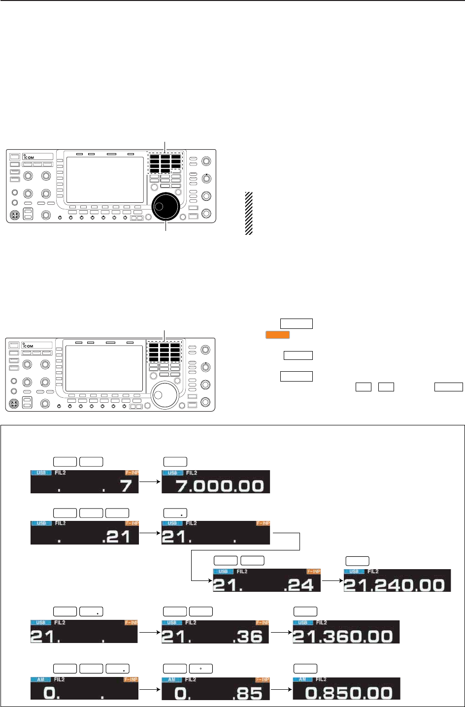
3-5
■Frequency setting
The transceiver has several tuning methods for conve-
nient frequency tuning.
D
Tuning with the main dial
qPush the desired band key on the keypad 1–3
times.
• 3 different frequencies can be selected on each band
with the band key.
wRotate the main dial to set the desired frequency.
If the dial lock function is activated, the lock indicator
lights, and the main dial does not function. In this
case, push [LOCK] to deactivate the lock function.
(see p. 5-17 for details)
3
BASIC OPERATIONS
[EXAMPLE]
7.00000 MHz
21.24000 MHz
21.24000 MHz ⇒ 21.36000 MHz
Push
Push
Push
1
1.8
2
3.5
2
3.5
3
7
4
10
6
18
7
21
ENT
F-INP
ENT
F-INP
ENT
F-INP
ENT
F-INP
ENT
F-INP
ENT
F-INP
GENE
GENE
850 kHz (0.85000 MHz)
Push
ENT
F-INP
ENT
F-INP GENE
8
24
0
50
5
14
Keypad
D
Direct frequency entry with the keypad
The transceiver has a keypad for direct frequency
entry as described below.
qPush .
• “ ” indicator appears and keypad backlight lights.
wInput the desired frequency
• Push to input “. (decimal point)” between the
MHz units and kHz units.
ePush to set the input frequency.
• To cancel the input, push / instead of .
F-INPENT
√
∫
F-INPENT
GENE •
F-INP
F-INPENT
Band keys
Main dial
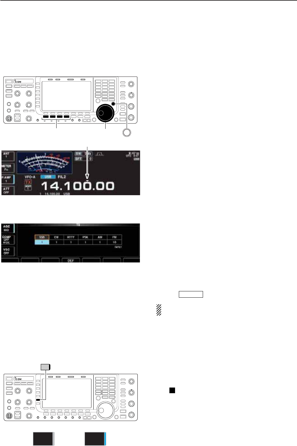
3-6
D
Quick tuning step
The operating frequency can be changed in larger
steps (0.1, 1, 5, 9, 10, 12.5, 20 or 25 kHz selectable)
for quick tuning.
qPush [TS] to turn the quick tuning function ON.
•“Z” appears when the quick tuning function is ON.
wRotate the main dial to change the frequency in pro-
grammed kHz steps.
ePush [TS] again to turn OFF the indicator.
rRotate the main dial for normal tuning if desired.
3BASIC OPERATIONS
Quick tuning indicator
D
1⁄4tuning step function
When operating in SSB data, CW, RTTY or PSK, the
1⁄4tuning function is available. Dial rotation is reduced
to 1⁄4of normal speed when the 1⁄4tuning function is
ON for finer tuning control.
➥Push [1/4] (MF6) to toggle the 1⁄4tuning function ON
and OFF.
• “ ” appears when the 1⁄4tuning function is ON.
1⁄4
D
Selecting “kHz” step
qPush [TS] to turn the quick tuning function ON and
OFF.
•“Z” appears when the quick tuning function ON.
wPush and hold [TS] for 1 sec. to enter quick tuning
step set mode.
• Selected tuning steps for all modes appear.
eSelect the desired operating mode.
r
Rotate the main dial to select the desired tuning step.
tRepeat steps eand rto select quick tuning steps
for other modes, if desired.
yPush to exit the setting display.
NOTE: When entering quick tuning step set mode,
the quick tuning function must be activated first.
EXIT/SET
Main dialSelect mode TS
1/4
1⁄4 tuning step OFF 1⁄4 tuning step ON
1/4
ON
1/4
OFF
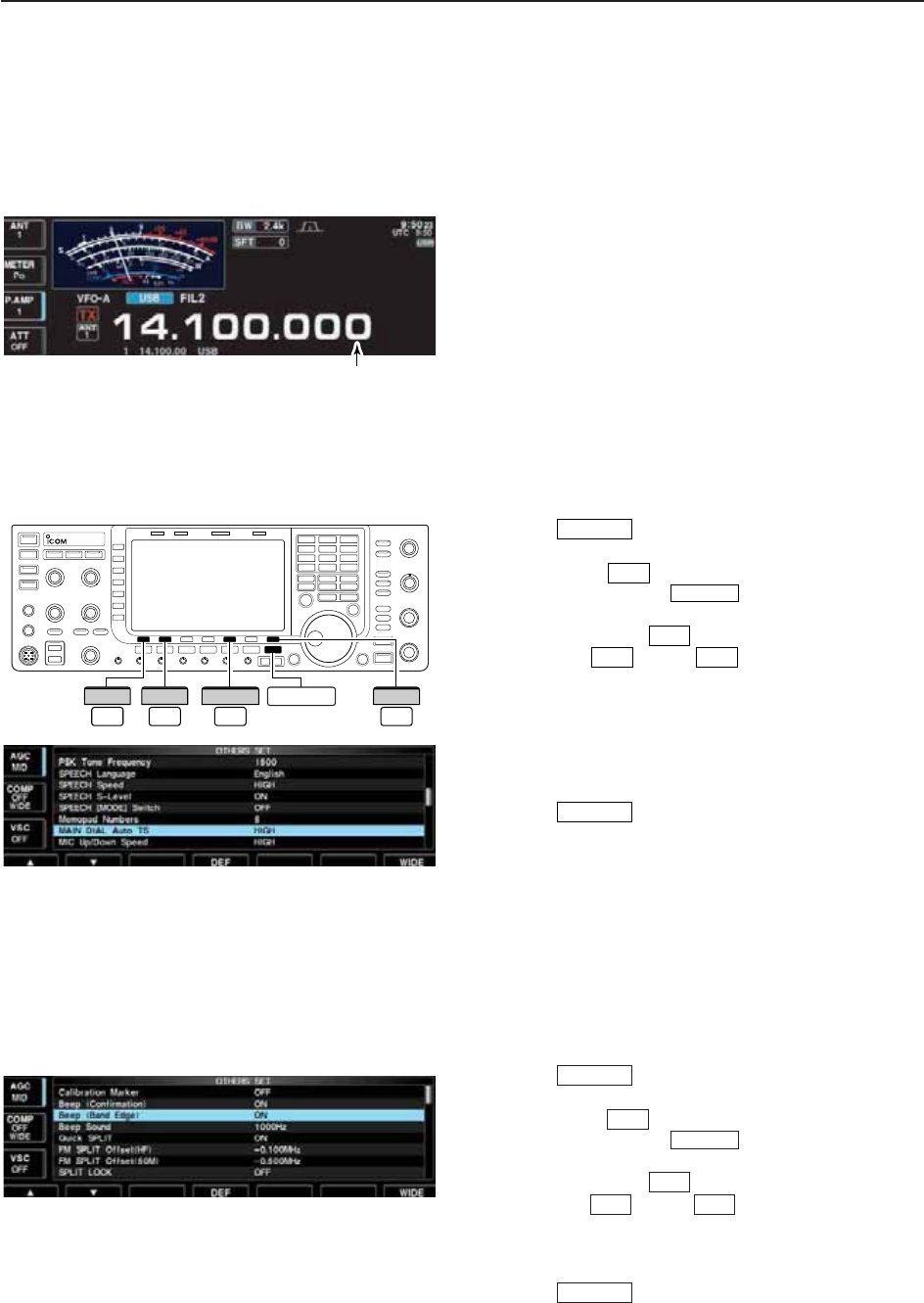
3-7
D
Selecting 1 Hz step
A minimum tuning step of 1 Hz can be used for fine
tuning.
qPush [TS] to turn the quick tuning function OFF.
wPush and hold [TS] for 1 sec. to turn the 1 Hz tuning
step ON and OFF.
3
BASIC OPERATIONS
D
Band edge warning beep
When you tune outside of an amateur band’s frequency
range, a warning beep sounds.
This function can be turned OFF in set mode, if de-
sired.
qPush several times to close a multi-func-
tion screen, if necessary.
wPush [SET] to select set mode menu screen.
• Pushing and holding for 1 sec. also selects set
mode menu screen.
ePush [OTHERS] to enter Others set mode.
rPush [Y] or [Z] to select “Beep (Band
Edge).”
tRotate the main dial to turn the band edge warning
beep ON and OFF.
yPush to exit the set mode.
EXIT/SET
F-2F-1
F-5
EXIT/SET
F-7
EXIT/SET
EXIT/SET
F-5
OTHERS
F-7
SET
F-1
∫
F-2
√
D
Auto tuning step function
When rotating the main dial rapidly, the tuning speed
accelerates automatically as selected.
qPush several times to close a multi-func-
tion screen, if necessary.
wPush [SET] to select set mode menu screen.
• Pushing and holding for 1 sec. also selects set
mode menu screen.
ePush [OTHERS] to enter Others set mode.
rPush [Y] or [Z] to select “MAIN DIAL
Auto TS.”
tRotate the main dial to select the desired condition
from high, low and OFF.
• High : Approx. 5 times faster
• Low : Approx. twice faster
• OFF : Auto tuning step is turned OFF.
yPush to exit the set mode.
EXIT/SET
F-2F-1
F-5
EXIT/SET
F-7
EXIT/SET
1Hz step indicator
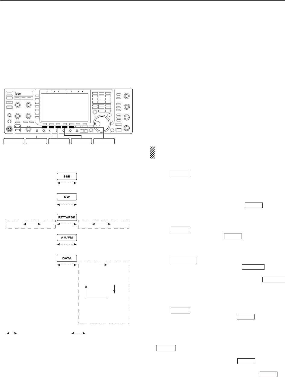
3-8
■Operating mode selection
SSB (USB/LSB), SSB data (USB data/LSB data), CW,
CW reverse (CW-R), RTTY, RTTY reverse (RTTY-R),
PSK, PSK reverse (PSK-R), AM, AM data, FM and FM
data modes are available in the IC-7700. Select the
desired operation mode as follows.
To select a mode of operation, push the desired mode
switch momentarily. Push the switch again to toggle
between USB and LSB, CW and CW-R, RTTY/RTTY-
R and PSK/PSK-R, AM and FM, if desired. Push and
hold the switch for 1 sec. to toggle between RTTY and
RTTY-R, PSK and PSK-R, if desired.
See the diagram below left for the order of selection.
Microphone signals are muted when data mode is
selected.
• Selecting SSB mode
➥Push to select USB or LSB.
• USB is selected first when above 10 MHz; or LSB is se-
lected first when below 10 MHz operation.
(USB is selected when 5 MHz band is selected for the
USA version.)
• After USB or LSB is selected, push to toggle
between USB and LSB.
• Selecting CW mode
➥Push to select CW.
• After CW is selected, push to toggle between
CW and CW reverse mode.
• Selecting RTTY/PSK mode
➥Push to select RTTY or PSK.
• After RTTY or PSK is selected, push to toggle
between RTTY and PSK.
• After RTTY or PSK is selected, push and hold
for 1 sec. to toggle between RTTY and RTTY reverse,
or, PSK and PSK reverse mode, respectively.
• Selecting AM/FM mode
➥Push to select AM or FM.
• After AM or FM is selected, push to toggle be-
tween AM and FM.
• Selecting DATA mode
➥After USB, LSB, AM or FM is selected, push
to select USB data, LSB data, AM data or
FM data mode, respectively.
• After data mode is selected, push to toggle be-
tween regular voice and data mode.
• After data mode is selected, push and hold for
1 sec. to select data 1, 2 and 3 in sequence.
DATA
DATA
DATA
AM/FM
AM/FM
RTTY/PSK
RTTY/PSK
RTTY/PSK
CW
CW
SSB
SSB
3BASIC OPERATIONS
RTTY/PSK AM/FM DATA
SSB CW
USB
CW
AM
Push mode switch
for 1 sec.
Push mode switch
momentarily.
LSB
CW-R
RTTY-R RTTY PSK PSK-R
FM
USB
LSB
AM
FM
USB-D1
LSB-D1
AM-D1
FM-D1
USB-D2
LSB-D2
AM-D2
FM-D2
USB-D3
LSB-D3
AM-D3
FM-D3
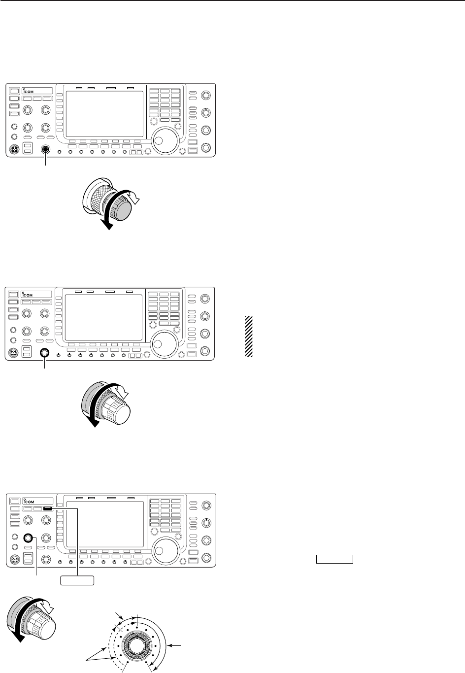
3-9
■Volume setting
➥Rotate [AF] control clockwise to increase, counter-
clockwise to decrease the audio output level.
• Set a suitable audio level.
3
BASIC OPERATIONS
■RF gain adjustment
➥Rotate [RF] control clockwise to increase, counter-
clockwise to decrease the receiver sensitivity.
NOTE:
When [RF] control is adjusted CCW in FM mode,
audio output decreases then disappears. This is nor-
mal, not a malfunction.
■Squelch level adjustment
The squelch mutes noise output from the speaker
(closed squelch) when no signal is received.
➥When no signal is received, rotate [SQL] control
fully counterclockwise first, then rotate [SQL] clock-
wise to the point that the noise just disappears.
• Push and hold to open the squelch temporar-
ily.
MONITOR
[AF]
Audio output
increases
Audio output
decreases
[RF]
Sensitivity
increases
Sensitivity
decreases
[SQL]
S-meter
squelch
Noise squelch
(Recommended level; FM mode only)
Squelch is
open
MONITOR
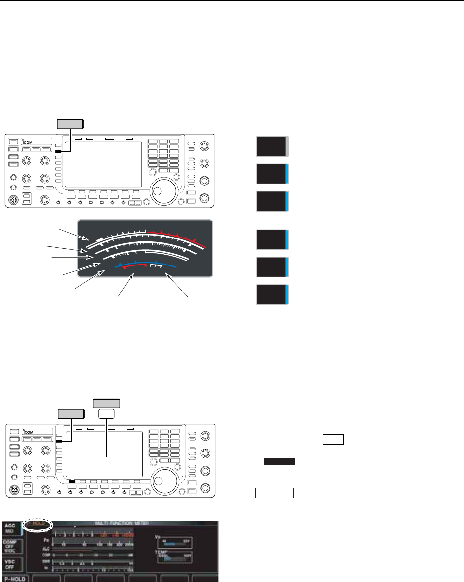
D
Multi-function digital meter
The IC-7700 can display the multi-function digital
meter on the LCD display. This meter displays all
transmit parameters simultaneously.
qPush and hold [METER] for 1 sec. to turn the multi-
function digital meter ON.
wPush [P-HOLD] to toggle the peak level hold
function ON.
• “ ” appears on the window title when the peak
level hold function is ON.
ePush and hold [METER] for 1 sec., or push
to turn the multi-function digital meter
OFF.
EXIT/SET
P-HOLD
F-1
■Meter indication selection
The S/RF meter indication, during transmit, can be se-
lected from the following items as you desire.
➥Push [METER] (MF2) several times to select the de-
sired item.
Indicates the RF output power in watts.
Indicates the VSWR on the transmission
line.
Indicates the ALC level. The ALC circuit
begins to activate when the RF output
power reaches a preset level.
Indicates the compression level when
the speech compressor is in use.
Indicates the drain current of the final
amplifier MOSFETs.
Indicates the drain terminal voltage of
the final amplifier MOSFETs.
METER
VD
METER
ID
METER
COMP
METER
ALC
METER
SWR
METER
Po
3-10
3BASIC OPERATIONS
“P-HOLD” indicator
METER
METER F-1
P-HOLD
S
1
0
0
0
1
2
510
10
10 20
44 52V
50 100 150 200 250
15
3
1.5
ID
VD
dB
WA
Po
SWR
COMP ALC
59+20 +40 +60dB
'
Signal strength
level readout
ID readout
Power level
readout
VSWR readout
Compression level
readout ALC level readout VD readout
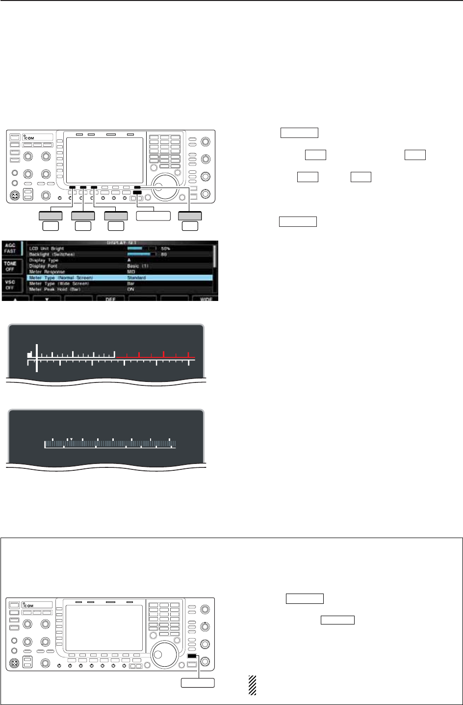
3-11
D
Meter type selection
A total of 3 meter types are available in the IC-7700—
Standard, Edgewise and Bar meters.
Follow the instructions below for the meter type selec-
tion.
qPush several times to return to normal
screen, if necessary.
wPush [SET] , then push [DISP] to select
display set mode.
ePush [Y] or [Z] to select “Meter type
(Normal Screen)” item.
rRotate the main dial to select the desired meter type
from “Standard,” “Edgewise” and “Bar.”
tPush to exit display set mode.
• Edgewise meter
• Bar meter
EXIT/SET
F-2F-1
F-3F-7
EXIT/SET
3
BASIC OPERATIONS
The IC-7700 has built-in voice synthesizer to an-
nounce the frequency, mode, etc. (S-meter level can
also be announced—p. 12-15) in clear, electroni-
cally-generated voice, in English (or Japanese).
➥Push to announce the currently se-
lected frequency, etc.
• Push and hold for 1 sec. to additionally an-
nounce the selected mode.
➥Pushing a mode switch also announces the ap-
propriate mode. (p. 12-15)
The output level of the voice synthesizer can be
adjusted in level set mode. (p. 12-6)
SPEECH
SPEECH
■Voice synthesizer operation
EXIT/SET
F-7
SET
F-3
DISP
F-1
∫
F-2
√
S
Po
13579
250W200100 150500
+20 +40 +60dB
S
Po
1357 9
250W200100 15050
0
10
+20 +40 +60dB
SPEECH
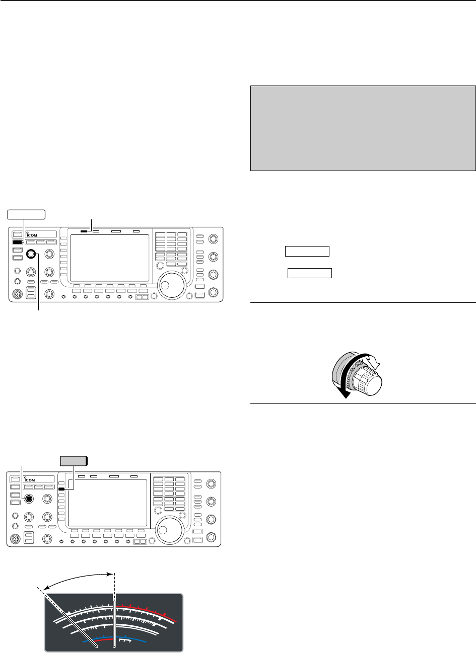
3-12
■Basic transmit operation
3BASIC OPERATIONS
D
Microphone gain adjustment
Before transmitting, monitor your selected operating
frequency to make sure transmitting won’t cause inter-
ference to other stations on the same frequency.
qPush [METER] (MF2) to select the ALC meter.
wPush [PTT] (microphone) to transmit.
• Talk into the microphone at your normal voice level.
eWhile talking into the microphone, rotate [MIC] so
that the ALC meter reading doesn’t go outside the
ALC zone. (see at left)
rRelease [PTT] (microphone) to return to receive.
[MIC] METER
S
1
0
0
0
1
2
510
10
10 20
44 52V
50 100 150 200 250
15
3
1.5
ID
VD
dB
WA
Po
SWR
COMP ALC
59+20 +40 +60dB
∞
ALC zone
[TX] indicator
[RF PWR]
TRANSMIT
Increases
max. 200 W
(50 W for AM)
Decreases
min. 5 W
D
Transmitting
Before transmitting, monitor your selected operating
frequency to make sure transmitting won’t cause inter-
ference to other stations on the same frequency.
qPush or [PTT] (microphone) to transmit.
• The [TX] indicator lights red.
wPush again or release [PTT] (micro-
phone) to return to receive.
✔
Adjusting the transmit output power
➥Rotate [RF PWR].
• Adjustable range : 5 W to 200 W
(AM mode: 5 W to 50 W)
TRANSMIT
TRANSMIT
Before transmitting, monitor your selected oper-
ating frequency to make sure transmitting won’t
cause interference to other stations on the same
frequency. It’s good amateur practice to listen
first, and then, even if nothing is heard, ask “is
the frequency in use” once or twice, before you
begin operating on that frequency.
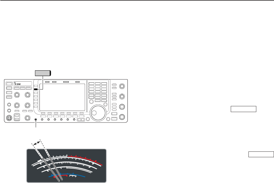
3-13
D
Drive gain adjustment
The drive gain is active for all modes other than SSB
mode with speech compressor OFF. The [DRIVE] con-
trol adjusts the amplifying gain at the driver stage.
Before transmitting, monitor your selected operating
frequency to make sure transmitting won’t cause inter-
ference to other stations on the same frequency.
qPush [METER] (MF2) to select the ALC meter.
wPush [PTT] (microphone; SSB with [COMP] ON, AM
or FM), key down (CW) or push (RTTY
or PSK) to transmit.
eWhile talking into the microphone, keying down or
transmitting, rotate [DRIVE] so that the ALC meter
reading is between 30 to 50% of the ALC scale. (see
left)
• Talk into the microphone at your normal voice level.
rRelease [PTT], stop keying or push
again to return to receive.
TRANSMIT
TRANSMIT
3
BASIC OPERATIONS
S
1
0
0
0
1
2
510
10
10 20
44 52V
50 100 150 200 250
15
3
1.5
ID
VD
dB
WA
Po
SWR
COMP ALC
59+20 +40 +60dB
∞
Drive gain range
[DRIVE]
METER

4-1
RECEIVE AND TRANSMIT Section 4
■Operating SSB ………………………………………………………… 4-2
DConvenient functions for receive ……………………………………4-2
DConvenient functions for transmit ……………………………………4-3
DAbout 5 MHz band operation (USA version only) …………………4-3
■Operating CW …………………………………………………………… 4-4
DConvenient functions for receive ……………………………………4-4
DConvenient functions for transmit ……………………………………4-5
DAbout CW reverse mode ……………………………………………4-5
DAbout CW pitch control ………………………………………………4-5
DCW side tone function ………………………………………………4-5
DAPF (Audio Peak Filter) operation …………………………………4-6
■Electronic keyer functions ……………………………………………… 4-7
DMemory keyer screen …………………………………………………4-8
DEditing a memory keyer ………………………………………………4-9
DContest number set mode …………………………………………4-10
DKeyer set mode ………………………………………………………4-11
■Operating RTTY (FSK) ……………………………………………… 4-13
DConvenient functions for receive …………………………………4-14
DAbout RTTY reverse mode …………………………………………4-14
DTwin peak filter ………………………………………………………4-14
DFunctions for the RTTY decoder indication ………………………4-15
DSetting the decoder threshold level ………………………………4-15
DRTTY memory transmission ………………………………………4-16
DAutomatic transmission/reception setting …………………………4-16
DEditing RTTY memory ………………………………………………4-17
DRTTY decode set mode ……………………………………………4-18
DData saving …………………………………………………………4-20
■Operating PSK ………………………………………………………… 4-21
DConvenient functions for receive …………………………………4-22
DAbout BPSK and QPSK modes ……………………………………4-22
DFunctions for the PSK decoder indication ………………………4-23
DSetting the decoder threshold level ………………………………4-23
DPSK memory transmission …………………………………………4-24
DAutomatic transmission/reception setting …………………………4-24
DEditing PSK memory ………………………………………………4-25
DPSK decode set mode ………………………………………………4-26
DData saving …………………………………………………………4-28
■Operating AM ………………………………………………………… 4-29
DConvenient functions for receive …………………………………4-29
DConvenient functions for transmit …………………………………4-30
■Operating FM ………………………………………………………… 4-31
DConvenient functions for receive …………………………………4-31
DConvenient functions for transmit …………………………………4-31
■Repeater operation …………………………………………………… 4-32
DRepeater tone frequency setting …………………………………4-33
■Tone squelch operation ……………………………………………… 4-34
■Data mode (AFSK) operation ………………………………………… 4-35
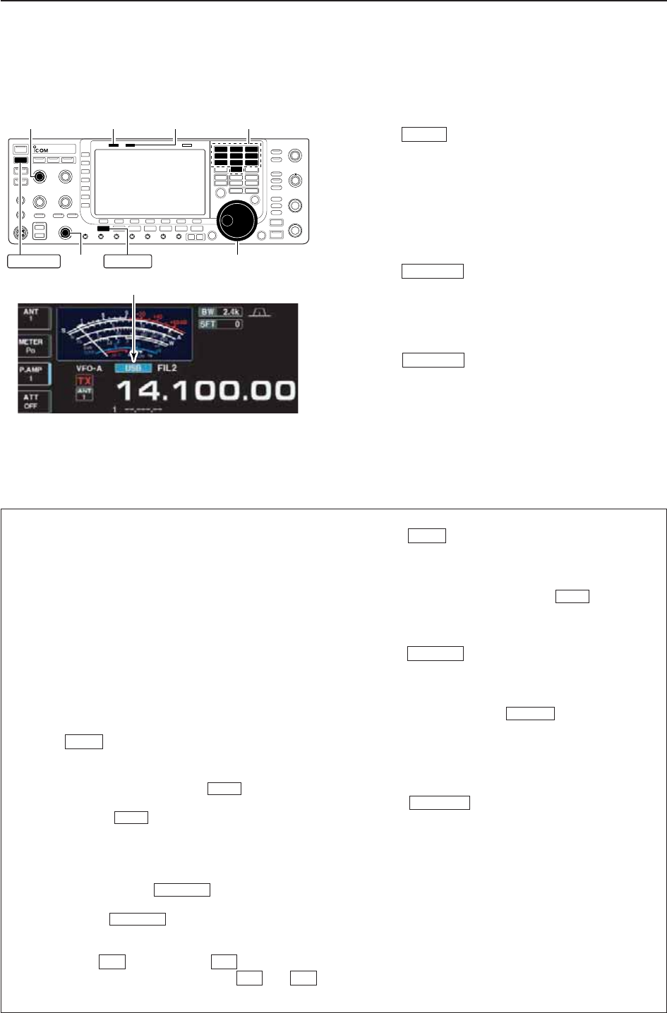
4-2
■Operating SSB
qPush a band key to select the desired band.
wPush to select LSB or USB.
• “USB” or “LSB” appears.
• Below 10 MHz LSB is automatically selected; above
10 MHz USB is automatically selected.
eRotate the main dial to tune a desired signal.
• The S-meter indicates received signal strength when a
signal is received.
rRotate [AF] to set audio to a comfortable listening
level.
tPush or [PTT] (microphone) to transmit.
• [TX] indicator lights red.
ySpeak into the microphone at your normal voice
level.
• Adjust the microphone gain with [MIC] at this step, if
necessary.
uPush or release [PTT] (microphone) to
return to receive.
TRANSMIT
TRANSMIT
SSB
4RECEIVE AND TRANSMIT
• Preamp (p. 5-9)
➥Push [P.AMP] (MF3) several times to set the pre-
amp OFF, preamp 1 ON or preamp 2 ON.
• “P.AMP1” or “P.AMP2” appears when the preamp 1 or
preamp 2 is ON, respectively.
• Attenuator (p. 5-9)
➥Push [ATT] (MF4) several times to set the attenu-
ator in 6 dB steps.
• Push and hold [ATT] (MF4) for 1 sec. to turn the
attenuator function OFF.
• “ATT” and attenuation level appear when the attenu-
ator is ON.
• Noise blanker (p. 5-16)
➥Push to turn the noise blanker ON and
OFF, and then rotate [NB] control to adjust the
threshold level.
• Noise blanker indicator (above switch) lights
when the noise blanker is ON.
• Push and hold for 1 sec. to enter noise blanker
set mode.
• Twin PBT (passband tuning) (p. 5-12)
➥Rotate [TWIN PBT] controls (inner/outer).
• PBT indicator (above switch) lights when
PBT is in use.
• Push and hold for 1 sec. to clear the settings.
• Audio tone control (p. 12-4)
➥Push [SET] then [LEVEL] to enter level
set mode. Select an item with [Y] /[Z]
then rotate the main dial to adjust the audio tone.
• Noise reduction (p. 5-17)
➥Push to turn the noise reduction ON and
OFF.
• Rotate [NR] control to adjust the noise reduction
level.
• Noise reduction indicator (above switch) lights
when the noise reduction is ON.
• Notch filter (p. 5-18)
➥Push to turn the auto or manual notch
function ON and OFF.
• Rotate [NOTCH] control to set the “valley” frequency
for manual notch operation.
• Notch indicator (above switch) lights when
either the auto or manual notch is ON.
• AGC (auto gain control) (p. 5-11)
➥Push [AGC] (MF5) switch several times to select
AGC FAST, AGC MID or AGC SLOW.
➥Push to turn the AGC time constant
manual setting ON and OFF.
• Rotate [AGC] control to adjust the time constant.
• VSC (voice squelch control) (p. 9-3)
➥Push [VSC] (MF7) to turn the VSC function ON
and OFF.
• The VSC indicator appears when the voice squelch
function is set to ON.
AGC VR
NOTCH
NOTCH
NR
NR
F-2F-1
F-1F-7
PBT-CLR
PBT-CLR
NB
NB
NB
D
Convenient functions for receive
[MIC] [TX] indicator [RX] indicator
[AF] Main dial
Band keys
SSBTRANSMIT
Appears
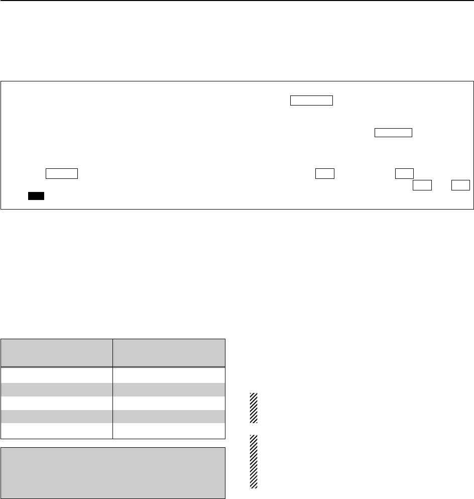
D
About 5 MHz band operation (USA version only)
Operation on the 5 MHz band is allowed on 5 discrete
frequencies and must adhere to the following:
• USB mode
• Maximum of 50 watts ERP (Effective Radiated Power)
• 2.8 kHz bandwidth
It’s your responsibility to set all controls so that trans-
mission in this band meets the stringent conditions
under which amateur operations may use these fre-
quencies.
NOTE: We recommend that you store these fre-
quencies, mode and filter settings into memory
channels for easy recall.
*The FCC specifies center frequencies on the
5 MHz band. However, the IC-7700 displays carri-
er frequency. Therefore, tune the transceiver to
1.5 kHz below the specified FCC channel center
frequency.
4-3
4
RECEIVE AND TRANSMIT
IC-7700 Tuning FCC Channel
Frequency* Center Frequency*
5.33050 MHz 5.33200 MHz
5.34650 MHz 5.34800 MHz
5.36650 MHz 5.36800 MHz
5.37150 MHz 5.37300 MHz
5.40350 MHz 5.40500 MHz
To assist you in operating the 5 MHz band within the
rules specified by the FCC, transmission is illegal on
any 5 MHz band frequency other than the five fre-
quencies indicated in the table above.
• Speech compressor (p. 6-5)
➥Push [COMP] (MF6) to turn the speech compres-
sor ON and OFF.
• Push and hold [COMP] (MF6) for 1 sec. to select the
compression bandwidth from wide, middle and nar-
row.
• VOX (voice operated transmit) (p. 6-2)
➥Push to turn the VOX function ON and
OFF.
• “ ” appears when the VOX function is ON.
• Transmit quality monitor (p. 6-4)
➥Push to turn the monitor function ON
and OFF.
• Rotate [MONI GAIN] to adjust the monitor gain.
• Monitor indicator (above switch) lights
when the monitor function is ON.
• Audio tone control (p. 12-5)
➥Push [SET] then [LEVEL] to enter level
set mode. Select an item with [Y] /[Z]
then rotate the main dial to adjust the audio tone.
F-2F-1
F-1F-7
MONITOR
MONITOR
VOX
VOX
D
Convenient functions for transmit
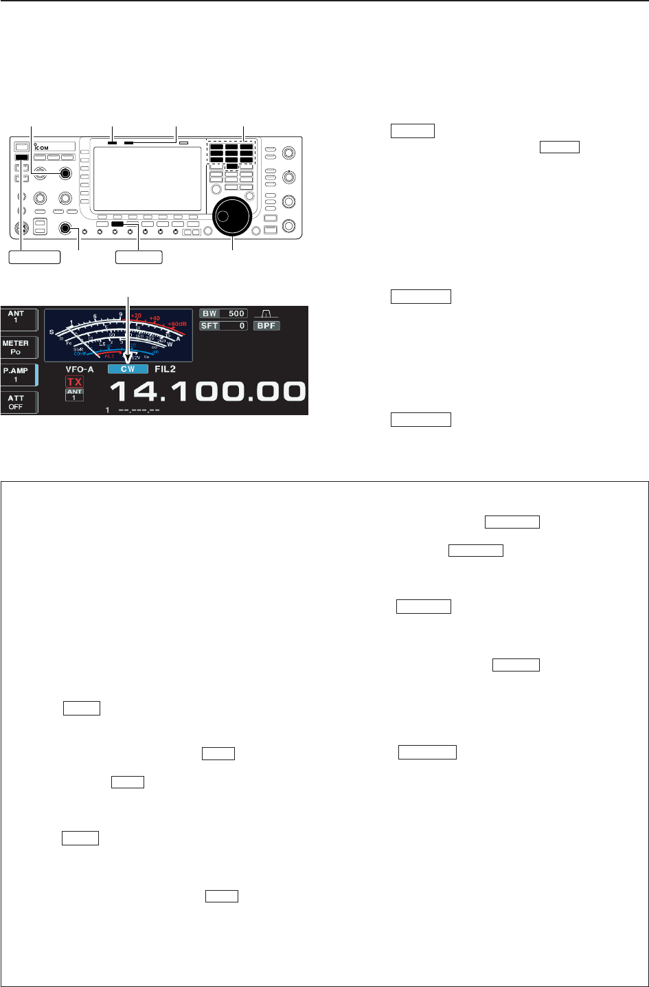
4-4
■Operating CW
qPush a band key to select the desired band.
wPush to select CW.
• After CW mode is selected, push to toggle be-
tween CW and CW-R modes.
• “CW” or “CW-R” appears.
eRotate the main dial to tune a desired signal.
• Try to match the specified signal’s tone to the side tone
frequency.
• The S-meter indicates received signal strength when
signal is received.
rRotate [AF] to set audio to a comfortable listening
level.
tPush to transmit.
• [TX] indicator lights red.
yUse the electric keyer or paddle to key your CW sig-
nals.
• The power meter indicates transmitted CW output
power.
uAdjust CW speed with [KEY SPEED].
• Adjustable within 6–48 WPM.
iPush to return to receive.
TRANSMIT
TRANSMIT
CW
CW
4RECEIVE AND TRANSMIT
• Preamp (p. 5-9)
➥Push [P.AMP] (MF3) several times to set the pre-
amp OFF, preamp 1 ON or preamp 2 ON.
• “P.AMP1” or “P.AMP2” appears when the preamp 1 or
preamp 2 is ON.
• Attenuator (p. 5-9)
➥Push [ATT] (MF4) several times to set the attenu-
ator in 6 dB steps.
• Push and hold [ATT] (MF4) for 1 sec. to turn the
attenuator function OFF.
• “ATT” and attenuation level appear when the attenu-
ator is ON.
• Noise blanker (p. 5-16)
➥Push to turn the noise blanker ON and
OFF, and then rotate [NB] control to adjust the
threshold level.
• Noise blanker indicator (above switch) lights
when the noise blanker is ON.
• Push and hold for 1 sec. to enter noise blanker
set mode.
• Noise reduction (p. 5-17)
➥Push to turn the noise reduction ON and
OFF.
• Rotate [NR] control to adjust the noise reduction
level.
• Noise reduction indicator (above switch) lights
when the noise reduction is ON.
• Twin PBT (passband tuning) (p. 5-12)
➥Rotate [TWIN PBT] controls (inner/outer).
• PBT indicator (above switch) lights when
PBT is in use.
• Push and hold for 1 sec. to clear the set-
tings.
• Manual notch filter (p. 5-18)
➥Push to turn the manual notch function
ON and OFF.
• Rotate [NOTCH] control to set the attenuating fre-
quency.
• Notch indicator (above switch) lights when
the manual notch is ON.
• AGC (auto gain control) (p. 5-11)
➥Push [AGC] switch several times to select
AGC FAST, AGC MID or AGC SLOW.
➥Push to turn the AGC time constant
manual setting ON and OFF.
• Rotate [AGC] control to adjust the time constant.
•1⁄4function (p. 3-6)
➥Push [1/4] to turn the 1⁄4function ON and OFF.
• Auto tuning function (p. 5-19)
➥Push [AUTOTUNE] to turn the auto tuning func-
tion ON and OFF.
• The transceiver automatically tunes the desired sig-
nal within a ±500 Hz range.
IMPORTANT!
When receiving a weak signal, or receiving a signal
with interference, the automatic tuning function may
not tune properly, or tune onto an undesired signal.
AGC VR
NOTCH
NOTCH
PBT-CLR
PBT-CLR
NR
NR
NB
NB
NB
D
Convenient functions for receive
[KEY SPEED] [TX] indicator [RX] indicator
[AF] Main dial
Band keys
CWTRANSMIT
Appears
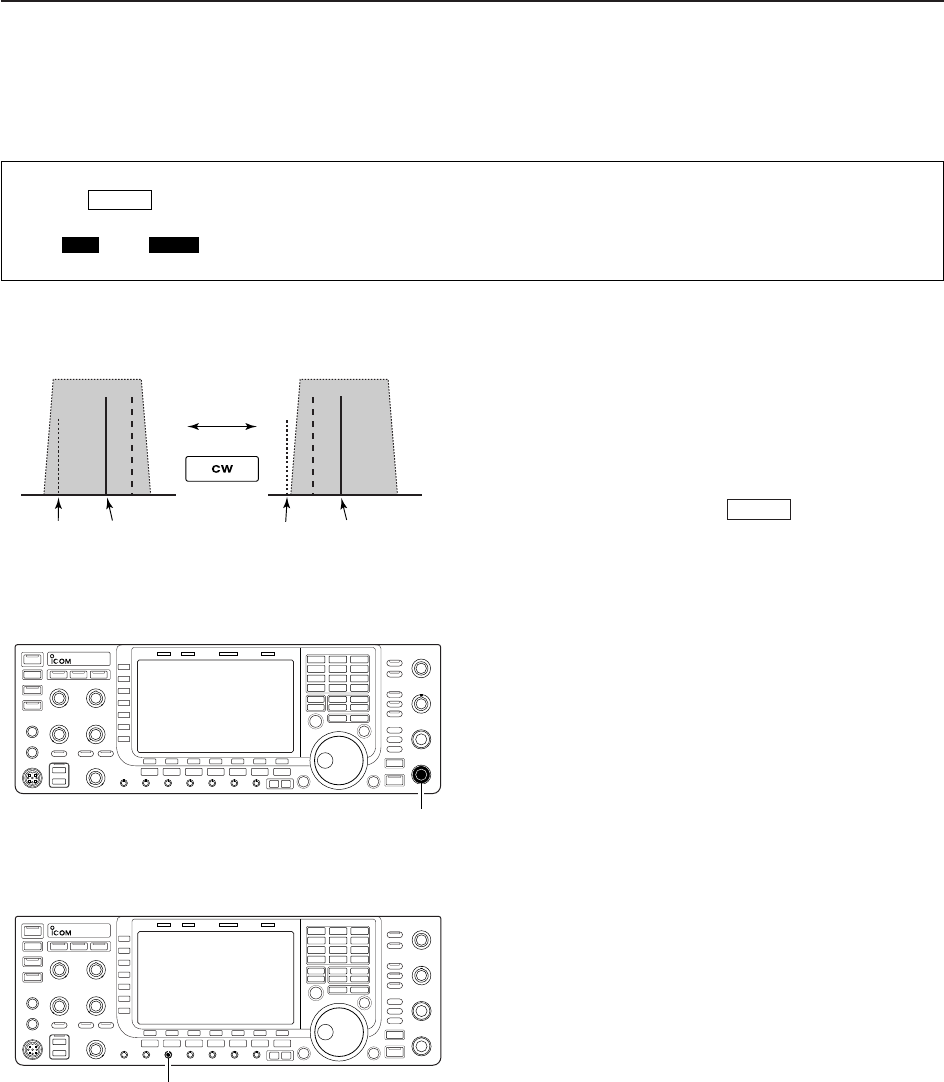
4-5
D
About CW reverse mode
CW-R (CW Reverse) mode uses the opposite side
band to receive CW signals.
Use when interfering signals are near a desired signal
and you want to use CW-R to reduce the interference.
➥During CW mode, push to select CW and
CW-R mode.
D
About CW pitch control
The received CW audio pitch and CW side tone can
be adjusted to suit your preference (from 300 to
900 Hz in 5 Hz steps). This does not change the oper-
ating frequency.
➥Rotate [CW PITCH] to suit your preference.
• Adjustable within 300 to 900 Hz in 5 Hz steps.
D
CW side tone function
When the transceiver is in receive (and the break-in
function is OFF— p. 6-3) you can listen to the CW side
tone without actually transmitting.
This allows you to match your transmit frequency ex-
actly to another station’s by matching the audio tone.
You can also use the CW side tone (be sure to turn
OFF break-in!) to practice CW sending. CW side tone
level can be adjusted in level set mode (p. 12-6).
CW
Push
BFO
CW-R mode (USB side)
BFO
Desired signal
CW mode (LSB side)
Interference Desired signalInterference
[CW PITCH]
[MONI GAIN]
4
RECEIVE AND TRANSMIT
• Break-in function (p. 6-3)
➥Push several times to select the break-in
OFF, semi break-in and full break-in.
• “ ” or “ ” appears when the semi break-
in or full break-in function is ON, respectively.
F-BKINBKIN
BK-IN
D
Convenient functions for transmit
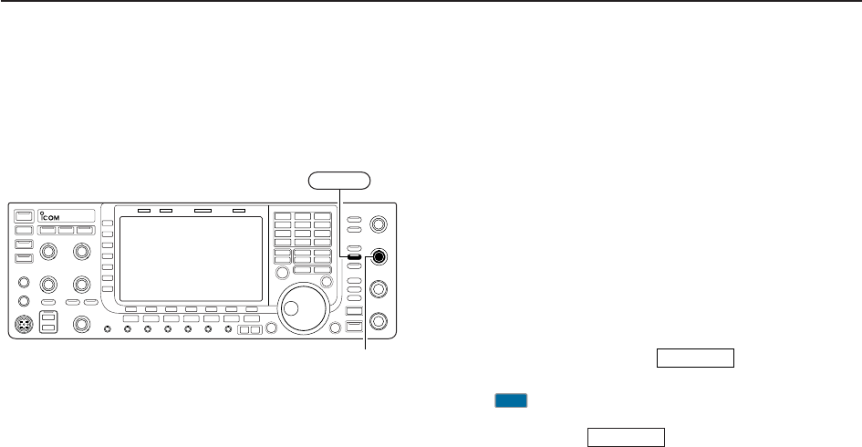
4-6
D
APF (Audio Peak Filter) operation
The APF changes the audio frequency response by
boosting a particular frequency to enhance a desired
CW signal.
The peak frequency can be adjusted with [DIGI-SEL]
control when “APF” is selected for “DIGI-SEL VR Op-
eration” in Others set mode (p. 12-16).
The audio filter shape is also selectable from “SOFT”
and “SHARP” in Others set mode (p. 12-16).
qDuring CW mode, push to turn the audio
peak filter ON and OFF.
• “ ” appears in the display and [APF/TPF] indicator
above this switch lights green.
wPush and hold for 1 sec. several times to
select the desired audio filter width.
• WIDE, MID and NAR filters, or, 320, 160 and 80 Hz fil-
ters are available depending on APF type setting in level
set mode.
eIf “APF” is selected for “DIGI-SEL VR Operation,”
rotate [DIGI-SEL] control to suit your preference.
APF/TPF
APF
APF/TPF
[DIGI-SEL]
APF/TPF
4RECEIVE AND TRANSMIT
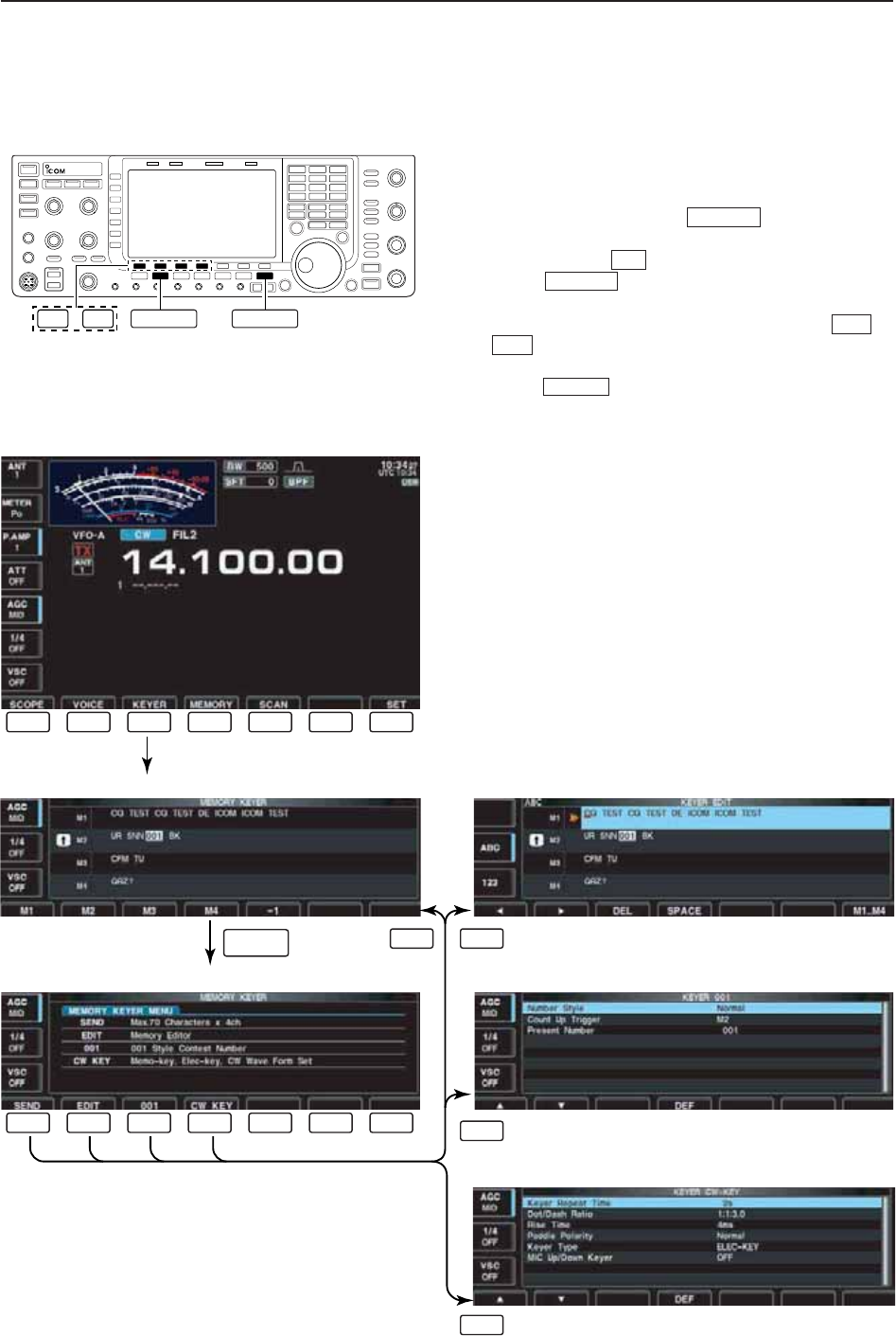
4-7
■Electronic keyer functions
The IC-7700 has a number of convenient functions for
the built-in electronic keyer.
qDuring CW mode, push several times to
normal screen, if necessary.
wPush [KEYER] to select memory keyer screen.
ePush to select memory keyer menu
screen.
rPush one of the LCD function switches ( to
) to select the desired menu. See the diagram
below.
• Push to return to the previous display.
EXIT/SET
F-4
F-1
EXIT/SET
F-3
EXIT/SET
• Memory keyer screen (p. 4-8)
• Memory keyer menu screen
• Memory keyer edit screen (p. 4-9)
• Contest number set mode (p. 4-10)
• Keyer set mode screen (p. 4-11)
F-1 F-2 F-3 F-4 F-5 F-6 F-7
F-1
F-1 F-2
F-3
F-4
F-2 F-3 F-4 F-5 F-6 F-7
EXIT/SET
–EXIT/SET
CW
F-1 F-4
4
RECEIVE AND TRANSMIT
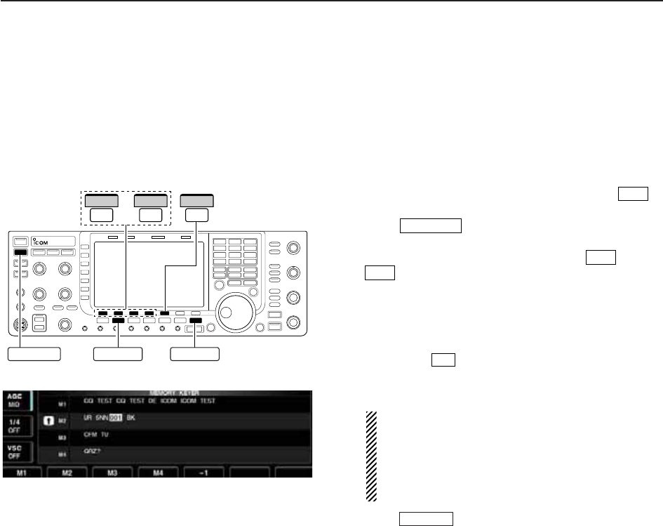
4-8
D
Memory keyer screen
Pre-set characters can be sent using the keyer send
menu. Contents of the memory keyer are set using the
edit menu.
• Transmitting
qDuring CW mode operation, push [KEYER] to
select memory keyer screen.
wPush to set the transceiver to transmit,
or set the break-in function ON (p. 6-3).
ePush one of the function keys ([M1] to [M4]
) to send the contents of the memory keyer.
• Pushing and holding a function key for 1 sec. repeatedly
sends the contents; push any function key to cancel the
transmission.
• The contest serial number counter is incremented each
time the contents are sent.
• Push [–1] to reduce the contest serial number
count by 1 when resending contents to unanswered
calls.
For your information
When an external keypad is connected to [EXT
KEYPAD] connector on the rear panel, the pro-
grammed contents, M1—M4, can be transmitted
without selecting the memory keyer screen.
See p. 2-7 for details.
rPush twice to return to normal screen.
EXIT/SET
F-5
F-4
F-1
TRANSMIT
F-3
–
EXIT/SET
CWTRANSMIT
F-1
M1
F-4
M4
F-5
–1
4RECEIVE AND TRANSMIT
• Memory keyer screen
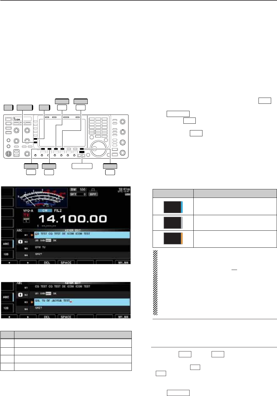
4-9
D
Editing a memory keyer
The contents of the memory keyer memories can be
set using the memory keyer edit menu. The memory
keyer can memorize and re-transmit 4 CW key codes
for often-used CW sentences, contest serial numbers,
etc. Total capacity of the memory keyer is 70 charac-
ters per memory channel.
• Programming contents
qDuring CW mode operation, push [KEYER] to
select memory keyer screen.
wPush to select memory keyer menu, then
push [EDIT] to select keyer edit screen.
• Memory keyer contents of Channel 1 (M1) is selected.
ePush [M1..M4] several times to select the de-
sired memory keyer channel to be edited.
rPush [ABC] (MF6) or [123] (MF7) or [Symbol] (MF7)
to select the character group, then rotate the main
dial to select the character, or push the keypad for
number input.
• [Symbol] appears when [123] (MF7) is pushed when
“123” character group is selected.
• Selectable characters (using the main dial);
NOTE:
“^” is used to transmit a following word with no
space such as AR. Put “^” before a text string
such as ^AR, and the string “AR ” is sent with no
space.
“✱” is used to insert the CW contest serial num-
ber. The serial number automatically increments
by 1. This function is only available for one mem-
ory keyer channel at a time. Memory keyer chan-
nel M2 used “✱” by default.
✔
For your convenience
When a PC keyboard is connected to [USB] con-
nector on the front panel, the memory keyer con-
tents can also be edited from the keyboard.
tPush [Ω] or [≈] to move the cursor
backwards or forwards, respectively.
• Pushing [DEL] deletes a character and [SPACE]
inserts a space.
yRepeat steps rand tto input the desired charac-
ters.
uPush twice to return normal screen.
EXIT/SET
F-4
F-3
F-2F-1
F-7
F-2
EXIT/SET
F-3
/
F-1
Ω
F-2
≈
F-7
M1..M4
F-3
DEL
F-4
SPACE
123 Symbol ABC
EXIT/SET
4
RECEIVE AND TRANSMIT
• Memory keyer edit screen
Key selection Editable characters
A to Z (capital letters)
0 to 9 (numbers)
/ ? ^ . , @ ✱
Symbol
123
ABC
• Example— entered “QSL TU DE JA3YUA TEST”
into memory keyer channel 3
CH Contents
M1 CQ TEST CQ TEST DE ICOM ICOM TEST
M2 UR 5NN✱BK
M3 CFM TU
M4 QRZ?
• Pre-programmed contents
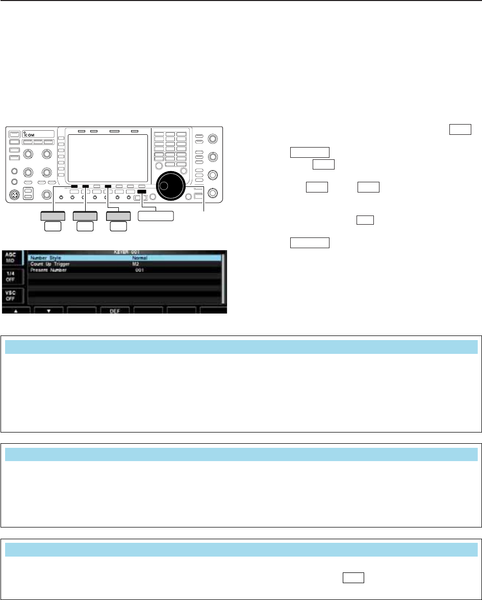
4-10
D
Contest number set mode
This menu is used to set the contest (serial) number
and count-up trigger, etc.
• Setting contents
qDuring CW mode operation, push [KEYER] to
select memory keyer screen.
wPush to select memory keyer menu, then
push [001] to select contest serial number set
mode.
ePush [Y] or [Z] to select the desired set
item.
rSet the desired condition using the main dial.
• Push and hold [DEF] for 1 sec. to select the de-
fault condition or value.
• Contest number set mode screen tPush twice to normal screen.
EXIT/SET
F-4
F-2F-1
F-3
EXIT/SET
F-3
Main dial
F-1
∫
F-2
√EXIT/SET
F-4
DEF
4RECEIVE AND TRANSMIT
This item sets the numbering system used for contest
(serial) numbers— normal or short morse numbers.
• Normal : Does not use short morse numbers
(default)
• 190➔ANO : Sets 1 as A, 9 as N and 0 as O.
• 190➔ANT : Sets 1 as A, 9 as N and 0 as T.
•90➔NO : Sets 9 as N and 0 as O.
•90➔NT : Sets 9 as N and 0 as T.
This selects which of the four memories will contain
the contest serial number exchange. The count-up
trigger allows the serial number to automatically in-
crement after each complete serial number exchange
is sent.
• M1, M2, M3 and M4 can be set. (default: M2)
This item shows the current number for the count-up
trigger channel set above.
• Rotate the main dial to change the number, or push
and hold [001CLR] for 1 sec. to reset the cur-
rent number to 001.
F-3
Number Style
Normal
Count Up Trigger
M2
Present Number
001
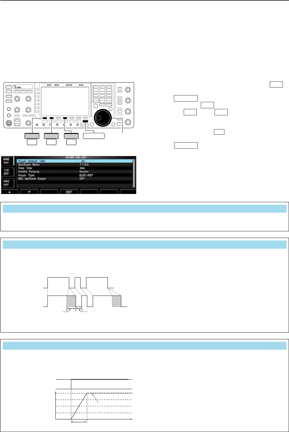
4-11
D
Keyer set mode
This set mode is used to set the memory keyer repeat
time, dash weight, paddle specifications, keyer type,
etc.
• Setting contents
qDuring CW mode operation, push [KEYER] to
select memory keyer screen.
wPush to select memory keyer menu, then
push [CW KEY] to select keyer set mode.
ePush [Y] or [Z] to select the desired set
item.
rSet the desired condition using the main dial.
• Push and hold [DEF] for 1 sec. to select the de-
fault condition or value.
tPush twice to normal screen.
• Keyer set mode screen
EXIT/SET
F-4
F-2F-1
F-4
EXIT/SET
F-3
Main dial
F-1
∫
F-2
√EXIT/SET
F-4
DEF
4
RECEIVE AND TRANSMIT
When sending CW using the repeat timer, this item
sets the time between transmission.
• 1 to 60 sec. in 1 sec. steps can be selected.
(default: 2 sec.)
This item sets the dot/dash ratio.
Keying weight example: Morse code “K”
• 1:1:2.8 to 1:1:4.5 (in 0.1 steps) can be selected.
(default: 1:1:3.0)
DASH
Weight setting:
1:1:3 (default)
Weight setting:
Adjusted
DASH
DOT (fixed*)
Adjustable range SPACE (fixed*)
*SPACE and DOT length can be
adjusted with [KEY SPEED] only.
This item sets the rise time of the transmitted CW en-
velope.
• 2, 4, 6 or 8 msec. can be selected. (default: 4 msec.)
Key action
Tx output power
• About rise time
Rise time
Tx
Rx
Set Tx power level
Time
0
to be continued…
Dot/Dash Ratio
1:1:3.0
Rise Time
4ms
Keyer Repeat Time
2s

4-12
D
Keyer set mode (continued)
4RECEIVE AND TRANSMIT
This item sets the paddle polarity. • Normal and reverse polarity can be selected.
This item selects the keyer type for [ELEC-KEY] con-
nector on the front panel.
• ELEC-KEY, BUG-KEY and Straight key can be se-
lected. (default: ELEC-KEY)
This item allows you to set the microphone [UP]/[DN]
keys to be used as a paddle.
•ON :[UP]/[DN] switches can be used for CW.
•OFF :[UP]/[DN] switches cannot be used for
CW.
NOTE: When “ON” is selected, the frequency and
memory channel cannot be changed using
the [UP]/[DN] switches.
Keyer Type
ELE-KEY
Mic Up/Down Keyer
OFF
Paddle Polarity
Normal
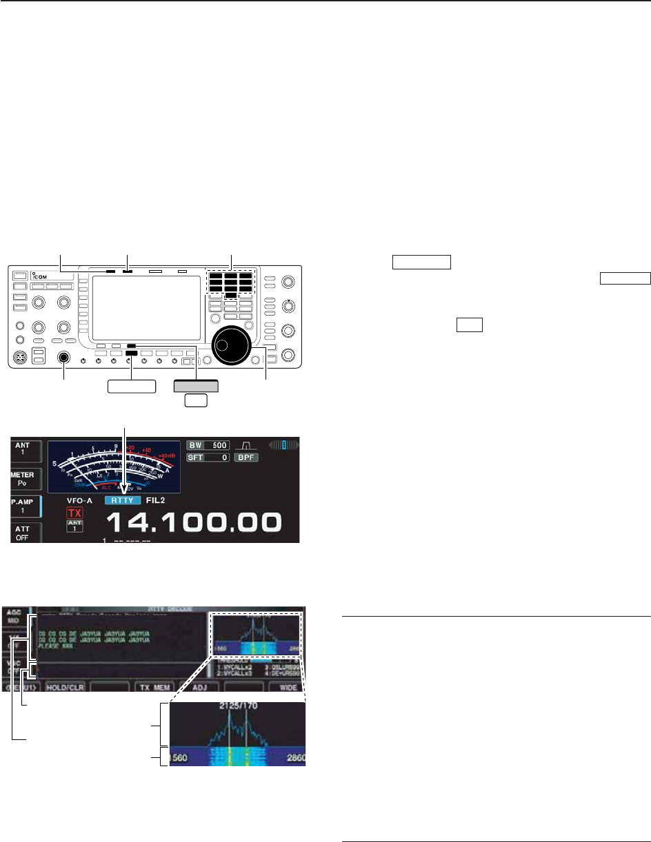
4-13
■Operating RTTY (FSK)
A DSP-based high-quality Baudot RTTY encoder/de-
coder is built-in to the IC-7700. When connecting a PC
keyboard (p. 2-6), RTTY operation can be performed
without an external RTTY terminal, TNC or PC.
If you would rather use your RTTY terminal or TNC,
consult the manual that comes with the RTTY terminal
or TNC.
qPush a band key to select the desired band.
wPush to select RTTY.
• After RTTY mode is selected, push and hold
for 1 sec. to toggle between RTTY and RTTY-R modes.
• “RTTY” or “RTTY-R” appears.
ePush [DECODE] to display the decode screen.
• The IC-7700 has a built-in Baudot decoder.
rTo tune the desired signal, aim for a symmetrical
waveform and ensure the peak points align with the
mark (2125 Hz) and shift (170 Hz) frequency lines
in the FFT scope.
• The S-meter indicates received signal strength when
signal is received.
tPress [F12] on the connected keyboard to transmit.
• [TX] indicator lights red.
yType from the keyboard to enter the contents that
you want to transmit.
• The typewritten contents are indicated in the TX buffer
screen and transmitted immediately.
• The text color will be changed when transmitted.
• Press one of [F1]–[F8] to transmit the TX memory con-
tents.
uPress [F12] on the keyboard to return to receive.
✔
For your convenience
The transmission contents can be typed before being
transmitted.
qPerform the steps qto rabove.
wType from the connected keyboard to enter the
message that you want to transmit.
• The typewritten contents are indicated in the TX buffer
screen.
ePress [F12] of the connected keyboard to transmit
the typewritten contents.
• The color of displayed text, in the TX buffer screen, will
be changed when transmitted.
• To cancel the transmission, press [F12] twice.
rPress [F12] of the keyboard to return to receive.
F-3
RTTY/PSK
RTTY/PSK
FFT scope
TX buffer screen
RX contents screen
Water-fall
Appears
[TX] indicator [RX] indicator
[AF] Main dial
Band keys
RTTY/PSK
F-3
DECODE
4
RECEIVE AND TRANSMIT
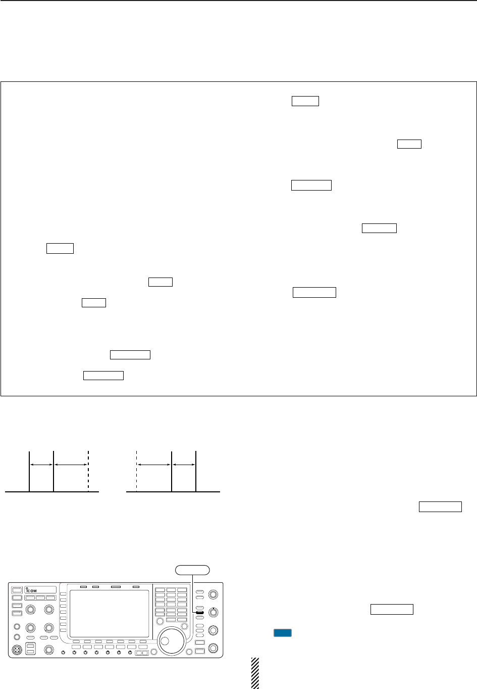
4-14
D
About RTTY reverse mode
Received characters are occasionally garbled when
the received signal has Mark and Space tones re-
versed. This reversal can be caused by incorrect TNC
connections, setting, commands, etc. To receive re-
versed RTTY signals correctly, select RTTY-R mode.
➥During RTTY mode, push and hold for
1 sec. to select RTTY and RTTY-R mode.
D
Twin peak filter
The twin peak filter changes audio frequency response
by boosting the mark and space frequencies (2125 and
2295 Hz) for better reception of RTTY signals.
➥During RTTY mode, push to turn the twin
peak filter ON and OFF.
• “ ” appears in the LCD and the [APF/TPF] indicator
above this switch lights green while the filter is in use.
NOTE: When the twin peak filter is in use, the re-
ceived audio output may increase. This is a normal,
not a malfunction.
TPF
APF/TPF
RTTY/PSK
APF/TPF
Normal Reverse
Space Mark BFO Space Mark
BFO
170 Hz 2125 Hz 170 Hz2125 Hz
4RECEIVE AND TRANSMIT
• Preamp (p. 5-9)
➥Push [P.AMP] (MF3) several times to set the pre-
amp OFF, preamp 1 ON or preamp 2 ON.
• “P.AMP1” or “P.AMP2” appears when the preamp 1 or
preamp 2 is ON.
• Attenuator (p. 5-9)
➥Push [ATT] (MF4) several times to set the attenu-
ator in 6 dB steps.
• Push and hold [ATT] (MF4) for 1 sec. to turn the atten-
uator function OFF.
• “ATT” and attenuation level appear when the attenu-
ator is ON.
• Noise blanker (p. 5-16)
➥Push to turn the noise blanker ON and
OFF, and then rotate [NB] control to adjust the
threshold level.
• Noise blanker indicator (above switch) lights
when the noise blanker is ON.
• Push and hold for 1 sec. to enter noise blanker
set mode.
• Twin PBT (passband tuning) (p. 5-12)
➥Rotate [TWIN PBT] controls (inner/outer).
• PBT indicator (above switch) lights when
PBT is in use.
• Push and hold for 1 sec. to clear the set-
tings.
• Noise reduction (p. 5-17)
➥Push to turn the noise reduction ON and
OFF.
• Rotate [NR] control to adjust the noise reduction
level.
• Noise reduction indicator (above switch) lights
when the noise reduction is ON.
• Manual notch filter (p. 5-18)
➥Push to turn the manual notch function
ON and OFF.
• Rotate [NOTCH] control to set the attenuating fre-
quency.
• Notch indicator (above switch) lights when
the manual notch is ON.
• AGC (auto gain control) (p. 5-11)
➥Push [AGC] switch several times to select
AGC FAST, AGC MID or AGC SLOW.
➥Push to turn the AGC time constant
manual setting ON and OFF.
• Rotate [AGC] control to adjust the time constant.
•1⁄4function (p. 3-6)
➥Push [1/4] to turn the 1⁄4function ON and OFF.
AGC VR
NOTCH
NOTCH
NR
NR
PBT-CLR
PBT-CLR
NB
NB
NB
D
Convenient functions for receive
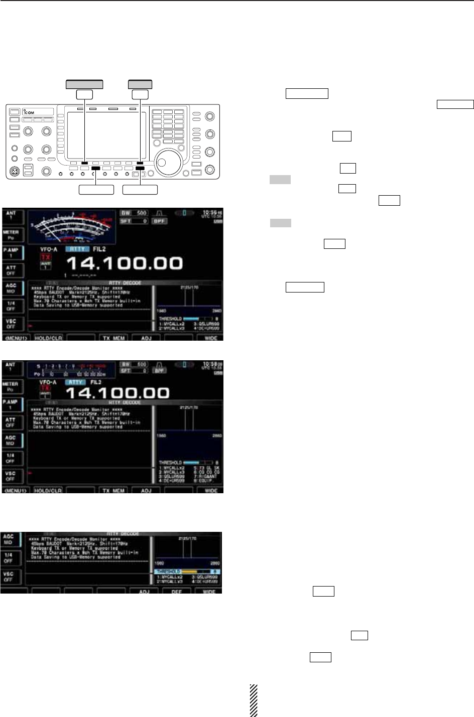
4-15
D
Functions for the RTTY decoder indication
qPush a band key to select the desired band.
wPush to select RTTY.
• After RTTY mode is selected, push and hold
for 1 sec. to toggle between RTTY and RTTY-R modes.
• “RTTY” or “RTTY-R” appears.
ePush [DECODE] to display the decode screen.
• When tuned into an RTTY signal, decoded characters
are displayed in the RX contents screen.
rPush [HOLD/CLR] to freeze the current screen.
• “ ” appears while the function is in use.
• Push [HOLD/CLR] again to release the function.
tPush and hold [HOLD/CLR] for 1 sec. to clear
the displayed characters.
•“ ” indicator disappears at the same time when the
hold function is in use.
yPush [WIDE] to toggle the RTTY decode
screen size from normal and wide.
• S/RF meter type during wide screen indication can be
selected in display set mode. (pgs. 3-11, 12-10)
uPush to close the RTTY decode screen.
• Wide screen indication
D
Setting the decoder threshold level
Adjust the RTTY decoder threshold level if some char-
acters are displayed when no signal is received.
qSelect the RTTY decode screen as described
above.
wPush [ADJ] to select the threshold level set-
ting condition.
eRotate the main dial to adjust the RTTY decoder
threshold level.
• Push and hold [DEF] for 1 sec. to select the de-
fault setting.
rPush [ADJ] to exit from the threshold level set-
ting condition.
The UnShift On Space (USOS) function and new
line code can be set in the RTTY set mode.
(p. 4-18)
F-5
F-6
F-5
EXIT/SET
F-7
HOLD
F-2
F-2
HOLD
F-2
F-3
RTTY/PSK
RTTY/PSK
RTTY/PSK EXIT/SET
F-7
WIDE
F-2
HOLD/CLR
4
RECEIVE AND TRANSMIT
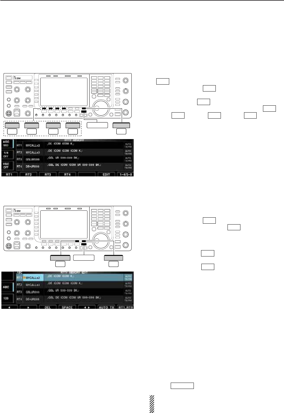
4-16
D
RTTY memory transmission
Pre-set characters can be sent using the RTTY mem-
ory. Contents of the memory are set using the edit
menu.
qDuring RTTY mode operation, push [DECODE]
to select RTTY decode screen.
wPush [TX MEM] to select RTTY memory
screen.
ePush [1–4/5–8] to select memory bank then
push one of the function keys ([RT1] to
[RT4] or [RT5] to [RT8] ).
• When no keyboard is connected, the selected memory
contents will be transmitted immediately.
• When a keyboard is connected, the memory contents
will be transmitted immediately when function key is
pushed, or transmitted after [F12] on the connected key-
board is pressed, depending on auto transmission/re-
ception setting (see below).
• The transmission date, time, reception date and/or time
may be displayed in RX contents screen, depending on
setting.
D
Automatic transmission/reception setting
qDuring RTTY mode operation, push [F-3•DECODE]
to select RTTY decode screen.
wPush [TX MEM] to select RTTY memory
screen, then push [EDIT] to select RTTY
memory edit screen.
• RTTY memory contents of the Channel 1 (RT1) is se-
lected.
ePush [RT1..RT8] several times to select the
desired RTTY memory.
rPush [AUTO TX] several times to select the
desired condition as follow.
• AUTO TX/RX : Automatically transmits the se-
lected memory and returns to re-
ceive after the transmission.
• AUTO TX : Automatically transmits the se-
lected memory. To return to re-
ceive, press [F12] on the key-
board.
• AUTO RX : Press [F12] on the keyboard to
transmit the selected memory. Au-
tomatically returns to receive after
the transmission.
• No indication : Press [F12] on the keyboard to
transmit the selected memory and
press [F12] again to return to re-
ceive.
tPush to exit RTTY memory edit condition.
NOTE: The transceiver always functions in the
“AUTO TX/RX” setting when no keyboard is con-
nected.
EXIT/SET
F-6
F-7
F-6
F-4
F-4F-1F-4
F-1
F-7
F-4
F-3
EXIT/SET
F-7
RT1..RT8
F-6
AUTO TX
––or F-7
1–4/5–8
F-1
RT1
F-4
RT4
F-1
RT5
F-4
RT8 EXIT/SET
4RECEIVE AND TRANSMIT
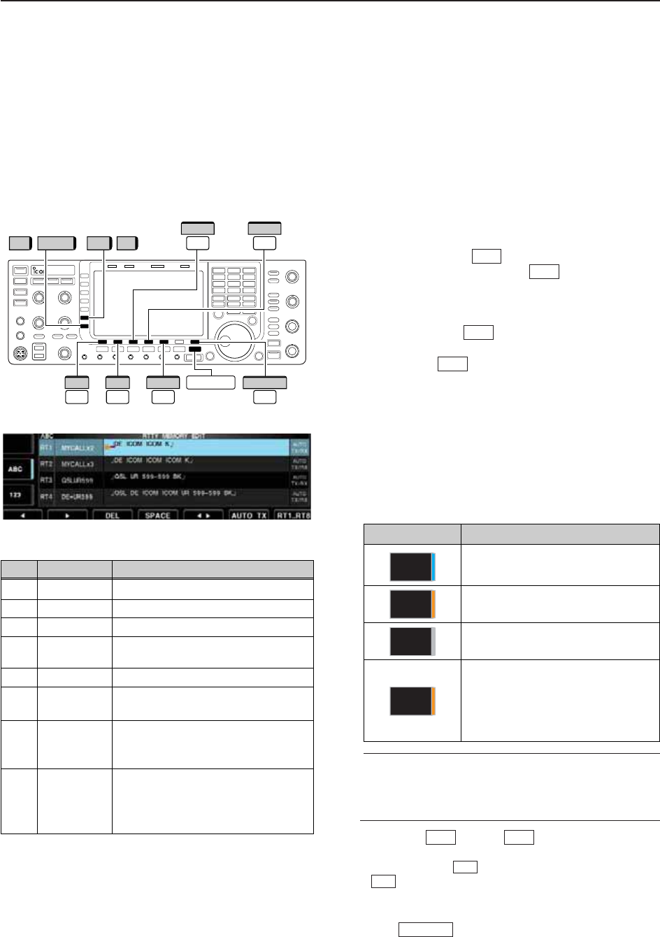
4-17
D
Editing RTTY memory
The contents of the RTTY memories can be set using
the memory edit menu. The memory can store and re-
transmit 8 RTTY message for often-used RTTY infor-
mation. Total capacity of the memory is 70 characters
per memory channel.
• Programming contents
qDuring RTTY mode operation, push [F-3•DECODE]
to select RTTY decode screen.
wPush [TX MEM] to select RTTY memory
screen, then push [EDIT] to select RTTY
memory edit screen.
• RTTY memory contents of the Channel 1 (RT1) is se-
lected.
ePush [RT1..RT8] to several times to select the
desired RTTY memory channel to be edited.
rPush [Ω≈] to select the edit item between
memory contents and memory name.
tPush [ABC] (MF6), [abc] (MF6), [123] (MF7) or [Sym-
bol] (MF7) to select the character group, then rotate
the main dial to select the character, or push the
keypad for number input.
• [abc] (MF6) appears when [ABC] (MF6) is pushed when
“ABC” character group is selected, and [Symbol] (MF7)
appears when [123] (MF7) is pushed when “123” char-
acter group is selected.
• Selectable characters (with the main dial);
✔
For your convenience
When a PC keyboard is connected to [USB] con-
nector on the front panel, the RTTY memory con-
tents can also be edited from the keyboard.
yPush [Ω] or [≈] to move the cursor
backwards or forwards, respectively.
• Pushing [DEL] deletes a character and [SPACE]
inserts a space.
uRepeat steps tand yto input the desired charac-
ters.
iPush to set the contents and exit RTTY
memory edit screen.
EXIT/SET
F-4
F-3
F-2F-1
F-5
F-7
F-6
F-4
RT1..RT8
EXIT/SET
F-7
//
F-3
DEL
F-4
SPACE
123 Symbol ABC abc
F-1
Ω
F-2
≈
F-5
Ω ≈
4
RECEIVE AND TRANSMIT
• RTTY memory edit screen
Key selection Editable characters
A to Z (capital letters)
a to z (small letters)
(selectable for memory name only)
0 to 9 (numbers)
! # $ % & ¥ ? “ ‘ ` ^ + – ✱/ . , : ; =
< > ( ) [ ] { } | _ ~@
(For the memory contents set-
ting, ! $ & ? “ ‘ – / . , : ; ( ) ¿are
selectable.)
Symbol
123
abc
ABC
CH Name Contents
RT1 MYCALLx2 ¿DE ICOM ICOM K¿
RT2 MYCALLx3 ¿DE ICOM ICOM ICOM K¿
RT3 QSLUR599 ¿QSL UR 599–599 BK¿
RT4 DE+UR599 ¿QSL DE ICOM ICOM UR 599–599
BK¿
RT5 73 GL SK ¿73 GL SK¿
RT6 CQ CQ CQ ¿CQ CQ CQ DE ICOM ICOM ICOM
K¿
RT7 RIG&ANT ¿MY TRANSCEIVER IS IC–7700 &
ANTENNA IS A 3–ELEMENT
TRIBAND YAGI.¿
RT8 EQUIP. ¿MY RTTY EQUIPMENT IS
INTERNAL FSK UNIT &
DEMODULATOR OF THE
IC–7700.¿
• Pre-programmed contents
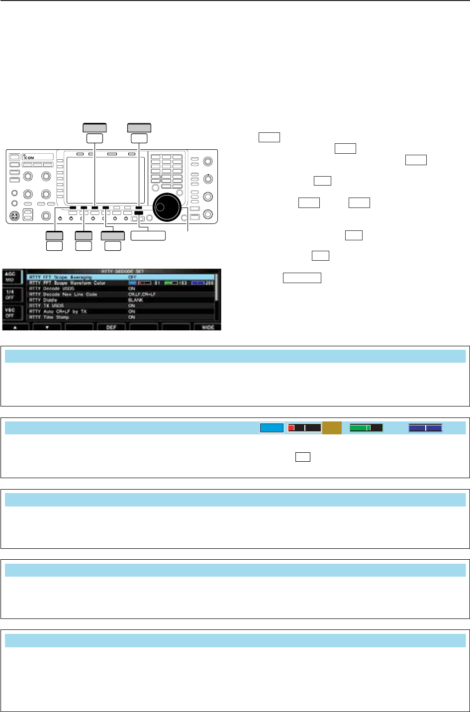
4-18
D
RTTY decode set mode
This set mode is used to set the decode USOS func-
tion, time stamp setting, etc.
• Setting contents
qDuring RTTY mode operation, push [DECODE]
to select RTTY decode screen.
wPush [<MENU1>] to select the second RTTY
decode menu, then push [SET] to select
RTTY decode set mode.
• Push [WIDE] to toggle the screen size from normal
and wide.
ePush [Y] or [Z] to select the desired set
item.
rSet the desired condition using the main dial.
• Push and hold [DEF] for 1 sec. to select a default
condition or value.
• Push [Ω≈] to select the set contents for some
items.
tPush to exit from set mode.
EXIT/SET
F-3
F-4
F-2F-1
F-7
F-6
F-1
F-3
F-3 F-7
WIDE
Ω ≈
Main dial
EXIT/SET
DEF
F-1
∫
F-2
√
F-4
4RECEIVE AND TRANSMIT
• RTTY decode set mode screen
Turn the capability of letter code decoding after re-
ceiving a “space” (USOS; UnShift On Space function)
ON and OFF.
• ON : Decode as letter code.
• OFF : Decode as character code.
Selects the new line code of the internal RTTY de-
coder.
CR: Carriage Return, LF: Line Feed
• CR,LF,CR+LF : Makes new line with any codes.
• CR+LF : Makes new line with CR+LF code
only.
RTTY Decode USOS
ON
RTTY Decode New Line Code
CR,LF,CR+LF
Selects the diddle condition. • BLANK : Transmits blank code during no code
transmission.
• LTRS : Transmits letter code during no code
transmission.
• OFF : Turns the diddle function OFF.
RTTY Diddle
BLANK
Select the FFT scope waveform averaging function
from 2 to 4 and OFF. (default: OFF)
Recommendation!
If you use the FFT scope waveform for tuning, use the
default or smaller number setting is recommended.
RTTY FFT Scope Averaging
OFF
Set the color for the FFT scope waveform.
• The color is set in RGB format.
• The set color is indicated in the box beside the RGB scale.
• Push [Ω≈] to select R (Red), G (Green) and B (Blue),
and then rotate the main dial to set the ratio from 0 to 255.
F-3
RTTY FFT Scope Waveform Color
51 153 255
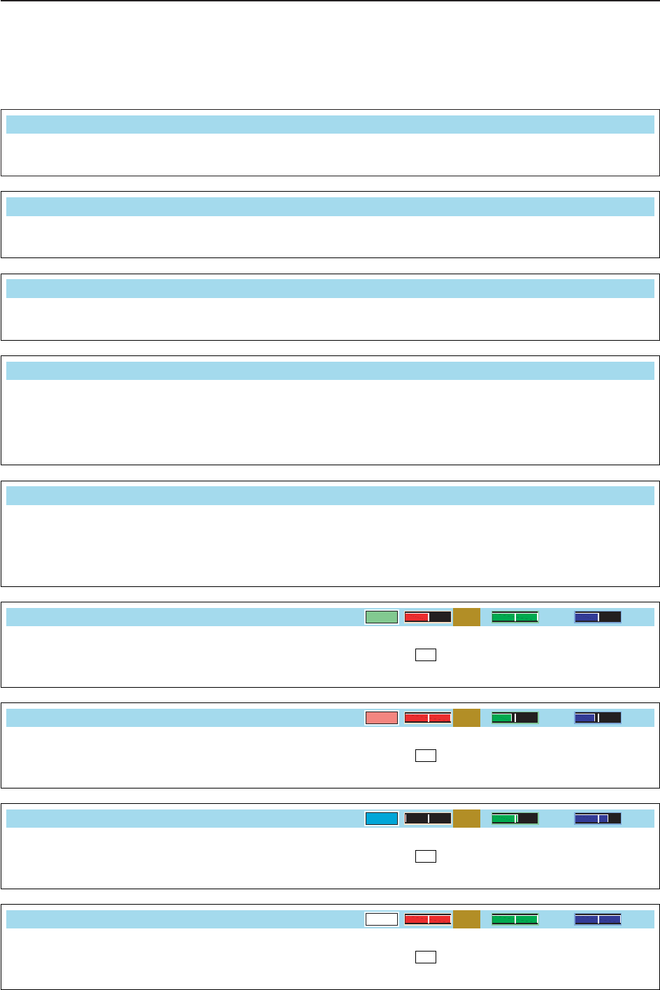
4-19
D
RTTY decode set mode (continued)
4
RECEIVE AND TRANSMIT
Explicitly inserts the FIGS character even though it is
not required by the receiving station.
• ON : Inserts FIGS.
• OFF : Does not insert FIGS.
RTTY TX USOS
ON
Turn the time stamp (date, transmission or reception
time) indication ON and OFF.
• ON : Displays the time stamp.
• OFF : No time stamp indication.
Selects the clock indication for time stamp usage.
NOTE: The time won’t be displayed when “OFF” is
selected in “RTTY Time Stamp” as above.
• Local : Selects the time that set in “Time (Now).”
• UTC* : Selects the time that set in “CLOCK2.”
*The name of choice may differ according to
“CLOCK2 Name” setting (p. 11-2). “UTC” is the
default name of CLOCK2.
RTTY Time Stamp
ON
RTTY Time Stamp (Time)
Local
Selects the automatic new line code (CR+LF) trans-
mission capability.
• ON : Transmits CR+LF code once.
• OFF : Transmits no CR+LF code.
RTTY Auto CR+LF by TX
ON
Set the text color for transmitted characters.
• The color is set in RGB format.
• The set color is indicated in the box beside the RGB scale.
• Push [Ω≈] to select R (Red), G (Green) and B (Blue),
and then rotate the main dial to set the ratio from 0 to 255.
F-3
RTTY Font Color (Transmit)
255 106 106
Selects the operating frequency indication for time
stamp usage.
NOTE: The frequency won’t be displayed when “OFF”
is selected in “RTTY Time Stamp” as above.
• ON : Displays the operating frequency.
• OFF : No operating frequency display.
Set the text color for received characters.
• The color is set in RGB format.
• The set color is indicated in the box beside the RGB scale.
• Push [Ω≈] to select R (Red), G (Green) and B (Blue),
and then rotate the main dial to set the ratio from 0 to 255.
F-3
RTTY Time Stamp (Frequency)
OFF
RTTY Font Color (Receive)
128 255 128
Set the text color for time stamp indication.
• The color is set in RGB format.
• The set color is indicated in the box beside the RGB scale.
• Push [Ω≈] to select R (Red), G (Green) and B (Blue),
and then rotate the main dial to set the ratio from 0 to 255.
F-3
Set the text color in the TX buffer screen.
• The color is set in RGB format.
• The set color is indicated in the box beside the RGB scale.
• Push [Ω≈] to select R (Red), G (Green) and B (Blue),
and then rotate the main dial to set the ratio from 0 to 255.
F-3
RTTY Font Color (Time Stamp)
0155 189
RTTY Font Color (TX Buffer)
255 255 255
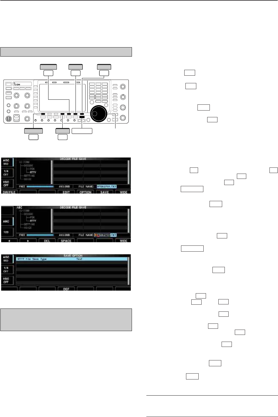
4-20
D
Data saving
The contents of the RTTY memory and received sig-
nal can be saved into the USB-Memory.
qDuring RTTY decode screen indication, push
[<MENU1>] to select the RTTY decode sec-
ond menu.
wPush [SAVE] to select decode file save screen.
eChange the following conditions if desired.
• File name:
zPush [EDIT] to select file name edit con-
dition.
• Push [DIR/FILE] several times to select the
file name, if necessary.
xPush [ABC] (MF6), [123] or [Symbol] (MF7) to
select the character group, then rotate the
main dial to select the character.
• [ABC] (MF6): A to Z (capital letters); [123] (MF7): 0
to 9 (numerals); [Symbol] (MF7): ! # $ % & ‘ ` ^ + –
= ( ) [ ] { } _ ~ @ can be selected.
•
Push [Ω] to move the cursor left, push [≈]
to move the cursor right, [DEL] delete a char-
acter and push [SPACE] to insert a space.
cPush to set the file name.
• File format
zPush [OPTION] to enter save option
screen.
xRotate the main dial to select the saving for-
mat from Text to HTML.
• “Text” is the default setting.
• Push and hold [DEF] for 1 sec. to select the
default setting.
cPush to return to the previous indi-
cation.
• Saving location
zPush [DIR/FILE] to select tree view
screen.
xSelect the desired directory or folder in the
USB-Memory.
• Push [Ω≈] to select the upper directory.
• Push [Y] or [Z] to select folder in the
same directory.
• Push and hold [Ω≈] for 1 sec. to select a
folder in the directory.
• Push [REN/DEL] to rename the folder.
• Push and hold [REN/DEL] for 1 sec. to
delete the folder.
• Push and hold [MAKE] for 1 sec. to making
a new folder. (Edit the name with the same man-
ner as the “• File name” above.)
cPush [DIR/FILE] twice to select the file
name.
rPush [SAVE] .
• After saving is completed, returns to RTTY decode sec-
ond menu automatically.
F-6
F-1
F-6
F-5
F-5
F-4
F-3
F-2
F-4
F-1
EXIT/SET
F-4
F-5
EXIT/SET
F-4
F-3
F-2F-1
F-1
F-4
F-5
F-1
Main dial
DIR/FILE EXIT/SET
F-1
F-7
WIDE
F-5
OPTION
F-6
SAVE
F-4
EDIT
4RECEIVE AND TRANSMIT
• Decode file save screen
• Decode file save screen— file name edit
• Save option screen
✔
For your convenience!
Two formats, Text and HTML, are available for storage
of data to your PC.
The USB-Memory is not supplied by Icom.
When a PC keyboard is connected to [USB] connec-
tor on the front panel, the file name can also be
edited from the keyboard.
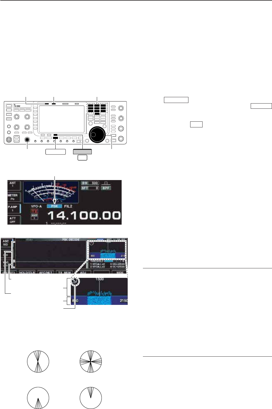
4-21
■Operating PSK
A high-quality DSP-based PSK31 encoder/decoder is
built-in to the IC-7700. When connecting a PC key-
board (p. 2-6), PSK31 operation can be performed
without PSK software installed on your PC.
If desired, you can also use your PSK software; con-
sult the manual that comes with the software.
qPush a band key to select the desired band.
wPush to select PSK.
• After PSK mode is selected, push and hold
for 1 sec. to toggle between PSK and PSK-R modes.
• “PSK” or “PSK-R” appears.
e
Push [DECODE] to display the decode screen.
• The IC-7700 has a built-in PSK31 decoder.
rTune to the desired signal with the main dial.
• The signal is properly tuned when the radiated lines in
the vector tuning indicator narrow, as show in the exam-
ple below.
• The radiated lines in the vector tuning indicator may be
displayed sporadically.
• When a PSK signal is received, the water-fall display is
activated.
• The water-fall display shows the signal condition within
the passband and a vertical line appears when a PSK
signal is received.
tPress [F12] of the connected keyboard to transmit.
• [TX] indicator lights red.
yType from the connected keyboard to enter the
message that you want to transmit.
• The typewritten contents are indicated in the TX buffer
screen and transmitted immediately.
• The text color will be changed when transmitted.
• Press one of [F1]–[F8] to transmit the TX memory con-
tents.
uPress [F12] of the keyboard to return to receive.
✔
For your convenience
The transmission contents can be typed before being
transmitted.
qPerform the steps qto rabove.
wType from the connected keyboard to enter the
message that you want to transmit.
• The message is shown in the TX buffer screen.
ePress [F12] of the connected keyboard to transmit
the message.
• The color of displayed text, in the TX buffer screen, will
be changed when transmitted.
• To cancel the transmission, press [F12] twice.
rPress [F12] of the keyboard to return to receive.
F-3
RTTY/PSK
RTTY/PSK
FFT scope
Vector tuning indicator
TX buffer screen
RX contents screen
Water-fall
Appears
[TX] indicator [RX] indicator
[AF] Main dial
Band keys
RTTY/PSK
F-3
DECODE
4
RECEIVE AND TRANSMIT
• Vector tuning indicator indication example
Tuned BPSK signal
BPSK/QPSK idle signal Unmodulated signal
Tuned QPSK signal
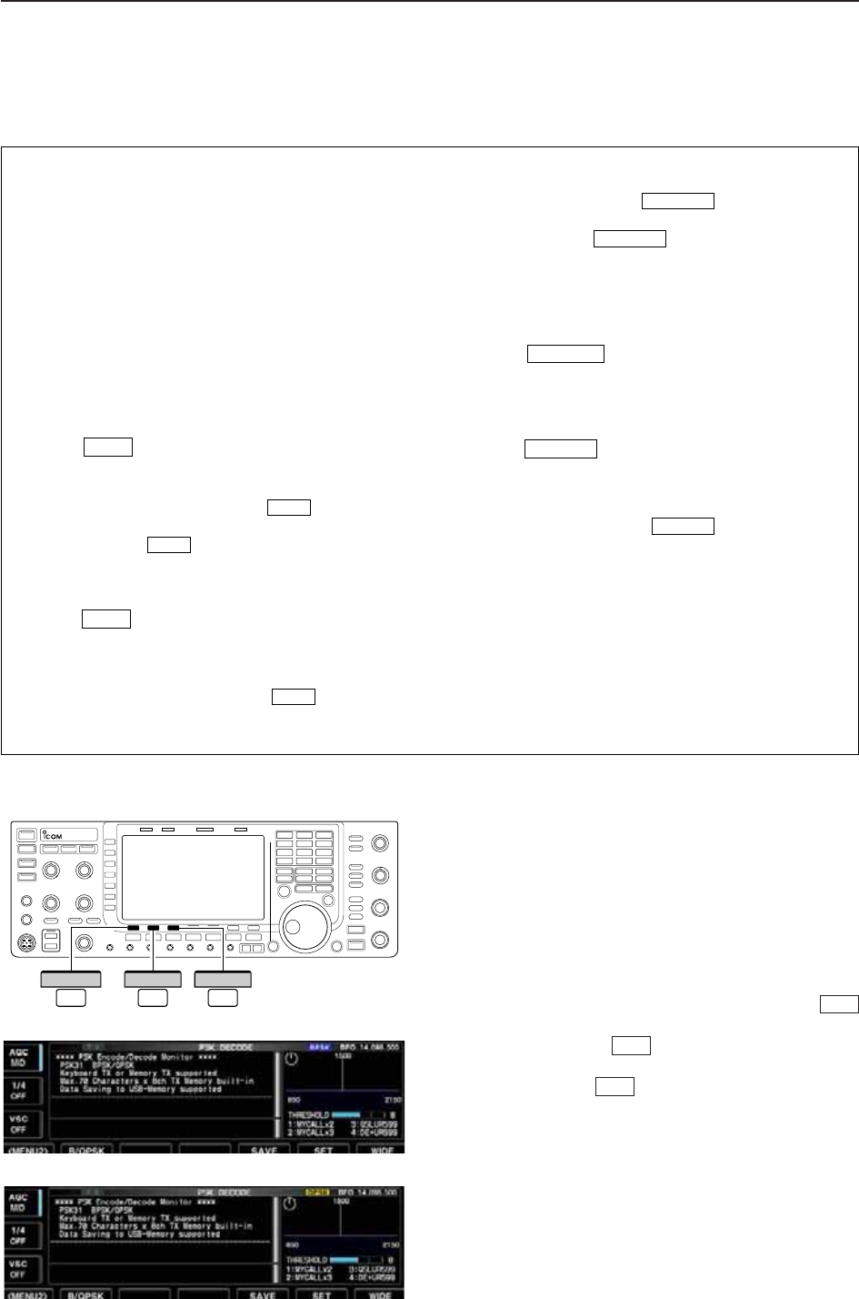
4-22
D
About BPSK and QPSK modes
BPSK and QPSK modes are available for PSK31.
• BPSK (Binary Phase Shift Keying) mode is the most
commonly used mode.
• QPSK (Quadrature Phase Shift Keying) mode has
error correction capability to provide better decoding
than BPSK mode in marginal condition. However,
more accurate tuning is required with QPSK mode,
due to the tight phase margin of QPSK.
qDuring PSK mode selection, push [DECODE]
to display the PSK decode screen.
wPush [<MENU1>] to select PSK decode sec-
ond menu.
ePush [B/QPSK] to toggle between BPSK and
QPSK mode alternately.
F-2
F-1
F-3
<
MENU1
>
F-1
DECODE
F-3
B/QPSK
F-2
4RECEIVE AND TRANSMIT
• PSK decode screen— BPSK mode
• PSK decode screen— QPSK mode
• Preamp (p. 5-9)
➥Push [P.AMP] (MF3) several times to set the pre-
amp OFF, preamp 1 ON or preamp 2 ON.
• “P.AMP1” or “P.AMP2” appears when the preamp 1 or
preamp 2 is ON.
• Attenuator (p. 5-9)
➥Push [ATT] (MF4) several times to set the attenu-
ator in 6 dB steps.
• Push and hold [ATT] (MF4) for 1 sec. to turn the atten-
uator function OFF.
• “ATT” and attenuation level appear when the attenu-
ator is ON.
• Noise blanker (p. 5-16)
➥Push to turn the noise blanker ON and
OFF, and then rotate [NB] control to adjust the
threshold level.
• Noise blanker indicator (above switch) lights
when the noise blanker is ON.
• Push and hold for 1 sec. to enter noise blanker
set mode.
• Noise reduction (p. 5-17)
➥Push to turn the noise reduction ON and
OFF.
• Rotate [NR] control to adjust the noise reduction
level.
• Noise reduction indicator (above switch) lights
when the noise reduction is ON.
• Twin PBT (passband tuning) (p. 5-12)
➥Rotate [TWIN PBT] controls (inner/outer).
• PBT indicator (above switch) lights when
PBT is in use.
• Push and hold for 1 sec. to clear the set-
tings.
• AGC (auto gain control) (p. 5-11)
➥Push [AGC] switch several times to select
AGC FAST, AGC MID or AGC SLOW.
➥Push to turn the AGC time constant
manual setting ON and OFF.
• Rotate [AGC] control to adjust the time constant.
• Manual notch filter (p. 5-18)
➥Push to turn the manual notch function
ON and OFF.
• Rotate [NOTCH] control to set the attenuating fre-
quency.
• Notch indicator (above switch) lights when
the manual notch is ON.
• Fine tuning (p. 3-7)
➥During PSK, make sure that the kHz tuning step
function is OFF (no “Z” indication), push and hold
[TS] for 1 sec.
• PSK may not be decoded correctly using the 10 Hz
step tuning.
•1⁄4function (p. 3-6)
➥Push [1/4] to turn the 1⁄4function ON and OFF.
NOTCH
NOTCH
AGC VR
PBT-CLR
PBT-CLR
NR
NR
NB
NB
NB
D
Convenient functions for receive
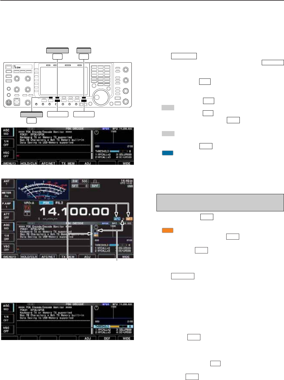
4-23
D
Functions for the PSK decoder indication
qPush a band key to select the desired band.
wPush to select PSK.
• After PSK mode is selected, push and hold
for 1 sec. to toggle between PSK and PSK-R modes.
• “PSK” or “PSK-R” appears.
ePush [DECODE] to display the decode screen.
• When tuned into a PSK signal, decoded characters are
displayed in the RX contents screen.
r
Push [HOLD/CLR] to freeze the current screen.
• “ ” appears while the function is in use.
• Push [HOLD/CLR] again to release the function.
tPush and hold [HOLD/CLR] for 1 sec. to clear
the displayed characters.
•“ ” indicator disappears at the same time when the
hold function is in use.
yPush [AFC/NET] to turn the AFC function ON.
• “ ” appears.
• If a PSK signal is received within the AFC tuning range,
the decoder automatically tunes into the signal and the
offset frequency is displayed.
• The AFC tuning range is set to ±15 Hz as the default.
Optional ±8 Hz setting is available in PSK decode set
mode. (p. 4-26)
uPush [AFC/NET] again to turn the NET func-
tion ON.
• “ ” appears additionally.
iPush and hold [AFC/NET] for 1 sec. to add
the offset frequency to the displayed frequency.
oPush [WIDE] to toggle the PSK decode
screen size from normal and wide.
• S/RF meter type during wide screen indication can be
selected in display set mode. (pgs. 3-11, 12-10)
!0 Push to close the PSK decode screen.
D
Setting the decoder threshold level
Adjust the PSK decoder threshold level if some char-
acters are displayed when no signal is received.
qCall up the PSK decode screen as described
above.
wPush [ADJ] to select the threshold level set-
ting condition.
eRotate the main dial to adjust the PSK decoder
threshold level.
• Push and hold [DEF] for 1 sec. to select the de-
fault setting.
rPush [ADJ] to exit from the threshold level set-
ting condition.
F-5
F-6
F-5
EXIT/SET
F-7
F-3
NET
F-3
NOTE: The AFC function may not tune the signal
properly when a weak PSK signal is received.
AFC
F-3
HOLD
F-2
F-2
HOLD
F-2
F-3
RTTY/PSK
RTTY/PSK
• AFC/NET indications
“AFC” and “NET” indicators Offset frequency
RTTY/PSK EXIT/SET
F-7
WIDE
F-3
AFC/NET
F-2
HOLD/CLR
4
RECEIVE AND TRANSMIT
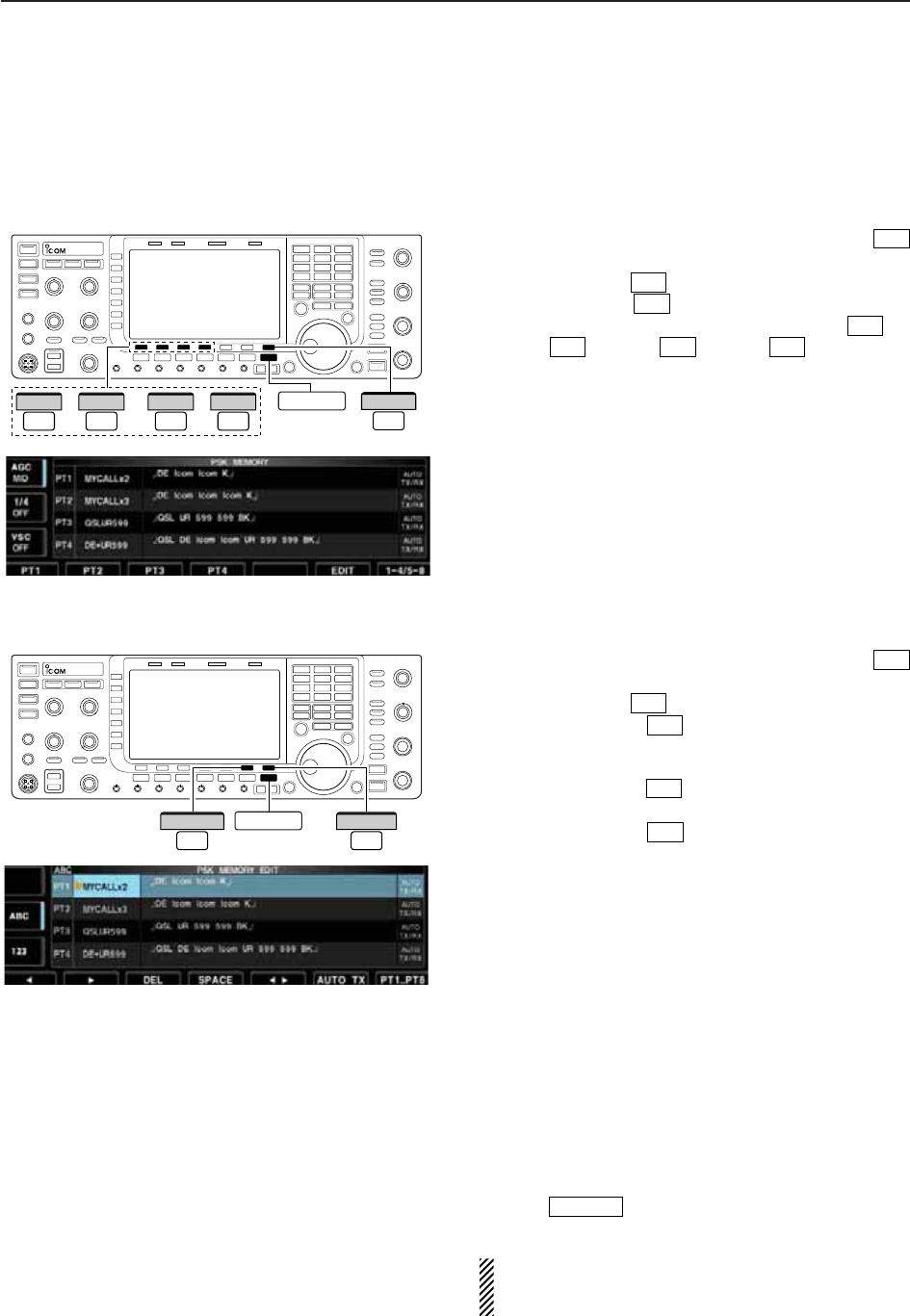
4-24
D
PSK memory transmission
Pre-set characters can be sent using the PSK memo-
ry. Contents of the memory are set using the edit
menu.
qDuring PSK mode operation, push [DECODE]
to select PSK decode screen.
wPush [TX MEM] to select PSK memory screen.
ePush [1–4/5–8] to select memory bank then
push one of the function keys ([PT1] to
[PT4] or [PT5] to [PT8] ).
• When no keyboard is connected, the selected memory
contents will be transmitted immediately.
• When a keyboard is connected, the memory contents
will be transmitted immediately when function key is
pushed, or transmitted after [F12] on the connected key-
board is pressed, depending on auto transmission/re-
ception setting (see below).
• The transmission date, time, reception date and/or time
may be displayed in RX contents screen, depending on
setting.
D
Automatic transmission/reception setting
qDuring PSK mode operation, push [DECODE]
to select PSK decode screen.
wPush [TX MEM] to select PSK memory screen,
then push [EDIT] to select PSK memory edit
screen.
• PSK memory contents of Channel 1 (PT1) is selected.
ePush [PT1..PT8] several times to select the
desired RTTY memory.
rPush [AUTO TX] several times to select the
desired condition, as follows.
• AUTO TX/RX : Automatically transmits the se-
lected memory and returns to re-
ceive after the transmission.
• AUTO TX : Automatically transmits the se-
lected memory. To return to re-
ceive, press [F12] on the key-
board.
• AUTO RX : Press [F12] on the keyboard to
transmit the selected memory. Au-
tomatically returns to receive after
the transmission.
• No indication : Press [F12] on the keyboard to
transmit the selected memory and
press [F12] again to return to re-
ceive.
tPush to return to exit from PSK memory
edit condition.
NOTE: The transceiver always functions in the
“AUTO TX/RX” setting when no keyboard is con-
nected.
EXIT/SET
F-6
F-7
F-6
F-4
F-3
F-4F-1F-4
F-1
F-7
F-4
F-3
EXIT/SET
F-7
PT1..PT8
F-6
AUTO TX
––or F-7
1–4/5–8
F-1
PT1
F-4
PT4
F-1
PT5
F-4
PT8 EXIT/SET
4RECEIVE AND TRANSMIT
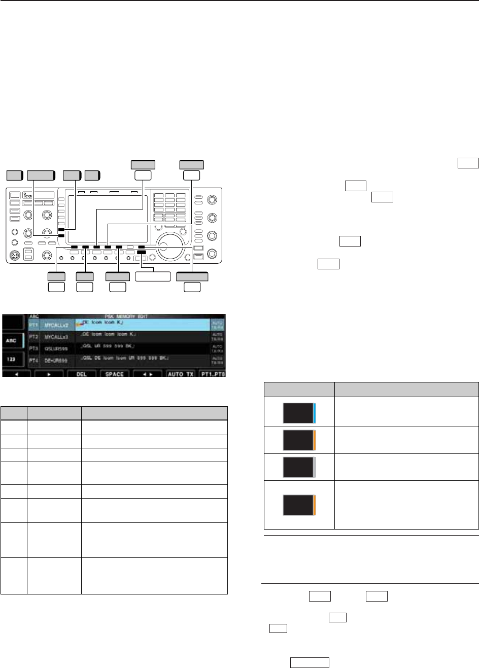
4-25
D
Editing PSK memory
The contents of the PSK memories can be set using
the memory edit menu. The memory can store 8 PSK
messages for often-used PSK information. Total
capacity of the memory is 70 characters per memory
channel.
• Programming contents
qDuring PSK mode operation, push [DECODE]
to select PSK decode screen.
wPush [TX MEM] to select PSK memory
screen, then push [EDIT] to select PSK mem-
ory edit screen.
• PSK memory contents of the Channel 1 (PT1) is se-
lected.
ePush [PT1..PT8] several times to select the
desired PSK memory channel to be edited.
rPush [Ω≈] to select the edit item between
memory contents and memory name.
tPush [ABC] (MF6), [abc] (MF6), [123] (MF7) or [Sym-
bol] (MF7) to select the character group, then rotate
the main dial to select the character, or push the
keypad for number input.
• [abc] (MF6) appears when [ABC] (MF6) is pushed when
“ABC” character group is selected, and [Symbol] (MF7)
appears when [123] (MF7) is pushed when “123” char-
acter group is selected.
• Selectable characters (with the main dial);
✔
For your convenience
When a PC keyboard is connected to [USB] con-
nector on the front panel, the PSK memory contents
can also be edited from the keyboard.
yPush [Ω] or [≈] to move the cursor
backwards or forwards, respectively.
• Pushing [DEL] deletes a character and [SPACE]
inserts a space.
uRepeat steps tand yto input the desired charac-
ters.
iPush to set the contents and exit PSK
memory edit screen.
EXIT/SET
F-4
F-3
F-2F-1
F-5
F-7
F-6
F-4
F-3
PT1..PT8
EXIT/SET
F-7
//
F-3
DEL
F-4
SPACE
123 Symbol ABC abc
F-1
Ω
F-2
≈
F-5
Ω ≈
4
RECEIVE AND TRANSMIT
Key selection Editable characters
A to Z (capital letters)
a to z (small letters)
0 to 9 (numbers)
! # $ % & ¥ ? “ ‘ ` ^ + – ✱/ . , : ; =
< > ( ) [ ] { } | _ ~@¿
(“¿” is for the memory contents set-
ting only.)
Symbol
123
abc
ABC
CH Name Contents
PT1 MYCALLx2 ¿DE Icom Icom K¿
PT2 MYCALLx3 ¿DE Icom Icom Icom K¿
PT3 QSLUR599 ¿QSL UR 599 599 BK¿
PT4 DE+UR599 ¿QSL DE Icom Icom UR 599 599
BK¿
PT5 73 GL SK ¿73 GL SK¿
PT6 CQ CQ CQ ¿CQ CQ CQ DE Icom Icom Icom
K¿
PT7 RIG&ANT ¿My transceiver is IC–7700 &
Antenna is a 3–element triband
yagi.¿
PT8 EQUIP. ¿My PSK equipment is internal
modulator & demodulator of the
IC–7700.¿
• Pre-programmed contents
• PSK memory edit screen
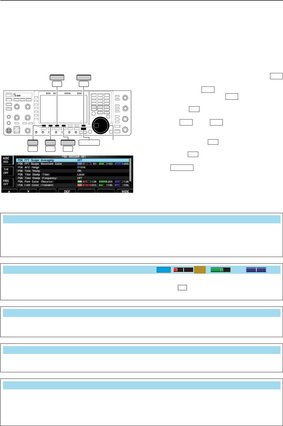
4-26
D
PSK decode set mode
This set mode is used to set the decode USOS func-
tion, time stamp setting, etc.
• Setting contents
qDuring PSK mode operation, push [DECODE]
to select PSK decode screen.
wPush [<MENU1>] to select PSK decode sec-
ond menu, then push [SET] to select PSK de-
code set mode.
• Push [WIDE] to toggle the screen size from normal
and wide.
ePush [Y] or [Z] to select the desired set
item.
rSet the desired condition using the main dial.
• Push and hold [DEF] for 1 sec. to select a default
condition or value.
• Push [Ω≈] to select the set contents for some
items.
tPush to exit from set mode.
EXIT/SET
F-3
F-4
F-2F-1
F-7
F-6
F-1
F-3
F-3 F-7
WIDE
Ω ≈
Main dial
EXIT/SET
DEF
F-1
∫
F-2
√
F-4
4RECEIVE AND TRANSMIT
Turn the time stamp (date, transmission or reception
time) display ON and OFF.
• ON : Displays the time stamp.
• OFF : No time stamp display.
PSK Time Stamp
ON
Selects the clock display for time stamp usage.
NOTE: The time won’t be displayed when “OFF” is
selected in “PSK Time Stamp” as above.
• Local : Selects the time that set in “Time (Now).”
• UTC* : Selects the time that set in “CLOCK2.”
*The name of choice may differ according to
“CLOCK2 Name” setting (p. 11-2). “UTC” is the
default name of CLOCK2.
PSK Time Stamp (Time)
Local
Select the FFT scope waveform averaging function
from 2 to 4 and OFF. (default: OFF)
Recommendation!
If you use the FFT scope waveform for tuning, using
the default or smaller number setting is recom-
mended.
PSK FFT Scope Averaging
OFF
Set the color for the FFT scope waveform.
• The color is set in RGB format.
• The set color is indicated in the box beside the RGB scale.
• Push [Ω≈] to select R (Red), G (Green) and B (Blue),
and then rotate the main dial to set the ratio from 0 to 255.
F-3
PSK FFT Scope Waveform Color
51 153 255
Select the AFC (Automatic Frequency Control) func-
tion operating range from ±15 Hz (default) and ±8 Hz.
NOTE: The AFC function may not tune the signal
properly when a weak PSK signal is received.
PSK AFC Range
±15Hz
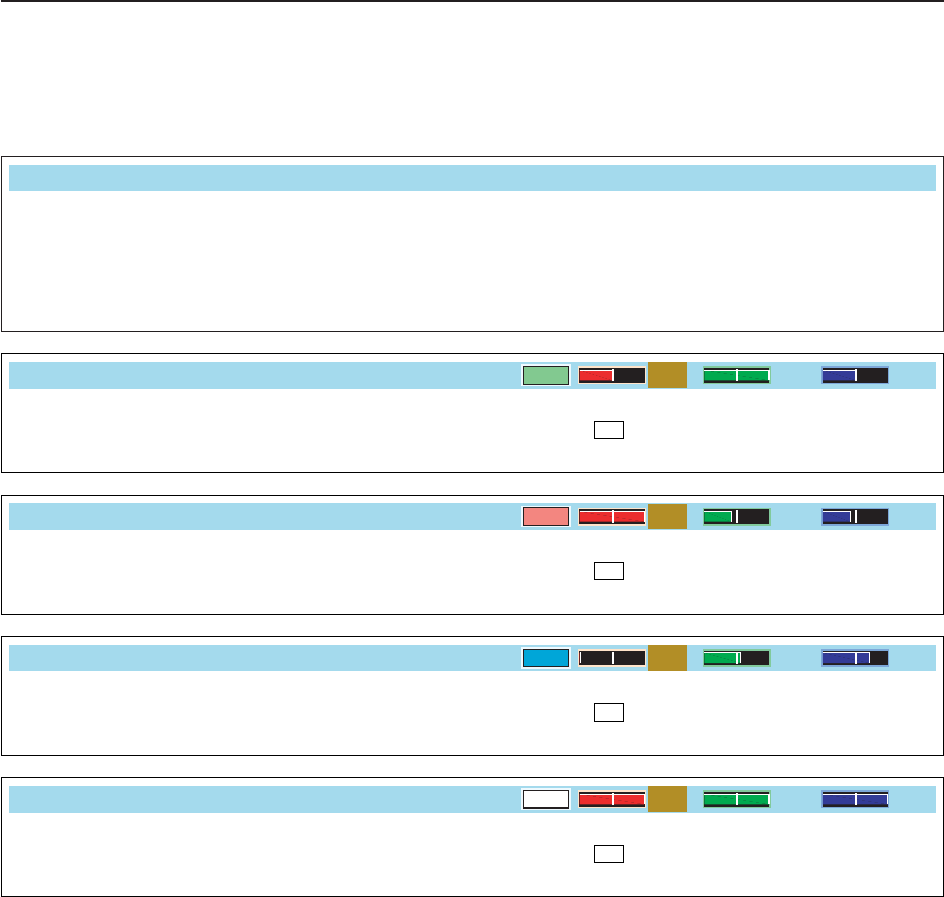
4-27
D
PSK decode set mode (continued)
4
RECEIVE AND TRANSMIT
Selects the operating frequency display for time
stamp usage.
NOTE: The frequency won’t be displayed when
“OFF” is selected in “PSK Time Stamp” as
below left.
• ON : Displays the operating frequency.
• OFF : No operating frequency display.
PSK Time Stamp (Frequency)
OFF
Set the text color for received characters.
• The color is set in RGB format.
• The set color is indicated in the box beside the RGB scale.
• Push [Ω≈] to select R (Red), G (Green) and B (Blue),
and then rotate the main dial to set the ratio from 0 to 255.
F-3
PSK Font Color (Receive)
128 255 128
Set the text color for transmitted characters.
• The color is set in RGB format.
• The set color is indicated in the box beside the RGB scale.
• Push [Ω≈] to select R (Red), G (Green) and B (Blue),
and then rotate the main dial to set the ratio from 0 to 255.
F-3
PSK Font Color (Transmit)
255 106 106
Set the text color for time stamp indication.
• The color is set in RGB format.
• The set color is indicated in the box beside the RGB scale.
• Push [Ω≈] to select R (Red), G (Green) and B (Blue),
and then rotate the main dial to set the ratio from 0 to 255.
F-3
PSK Font Color (Time Stamp)
0155 189
Set the text color in the TX buffer screen.
• The color is set in RGB format.
• The set color is indicated in the box beside the RGB scale.
• Push [Ω≈] to select R (Red), G (Green) and B (Blue),
and then rotate the main dial to set the ratio from 0 to 255.
F-3
PSK Font Color (TX Buffer)
255 255 255
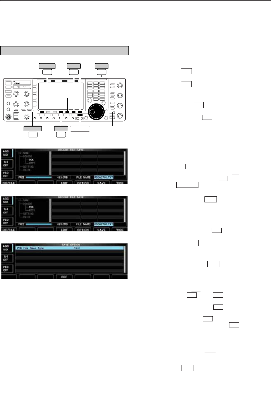
4-28
D
Data saving
The contents of the PSK memory and received signal
can be saved into the USB-Memory.
qDuring PSK decode screen indication, push
[<MENU1>] to select PSK decode second
menu.
wPush [SAVE] to select decode file save screen.
eChange the following conditions if desired.
• File name:
zPush [EDIT] to select file name edit con-
dition.
• Push [DIR/FILE] several times to select the
file name, if necessary.
xPush [ABC] (MF6), [123] (MF7) or [Symbol]
(MF7) to select the character group, then ro-
tate the main dial to select the character.
• [ABC] (MF6) : A to Z (capital letters); [123] (MF7): 0
to 9 (numerals); [Symbol] (MF7): ! # $ % & ‘ ` ^ + –
= ( ) [ ] { } _ ~ @ can be selected.
•
Push [Ω] to move the cursor left, push [≈]
to move the cursor right, [DEL] delete a char-
acter and push [SPACE] to insert a space.
cPush to set the file name.
• File format
zPush [OPTION] to enter save option
screen.
xRotate the main dial to select the saving for-
mat from Text and HTML.
• “Text” is the default setting.
• Push and hold [DEF] for 1 sec. to select the
default setting.
cPush to return to the previous indi-
cation.
• Saving location
zPush [DIR/FILE] to select tree view
screen.
xSelect the desired directory or folder in the
USB-Memory.
• Push [Ω≈] to select the upper directory.
• Push [Y] or [Z] to select folder in the
same directory.
• Push and hold [Ω≈] for 1 sec. to select a
folder in the directory.
• Push [REN/DEL] to rename the folder.
• Push and hold [REN/DEL] for 1 sec. to
delete the folder.
• Push and hold [MAKE] for 1 sec. to make a
new folder. (Edit the name with the same manner
as the “• File name” above.)
cPush [DIR/FILE] twice to select the file
name.
rPush [SAVE] .
• After saving is completed, return to PSK decode second
menu automatically.
F-6
F-1
F-6
F-5
F-5
F-4
F-3F-2
F-4
F-1
EXIT/SET
F-4
F-5
EXIT/SET
F-4
F-3
F-2F-1
F-1
F-4
F-5
F-1
Main dial
DIR/FILE EXIT/SET
F-1
F-7
WIDE
F-5
OPTION
F-6
SAVE
F-4
EDIT
4RECEIVE AND TRANSMIT
• Decode file save screen
• Decode file save screen— file name edit
• Save option screen
✔
For your convenience!
Two data formats, Text and HTML, are available for
PC data storage.
The USB-Memory is not supplied by Icom.
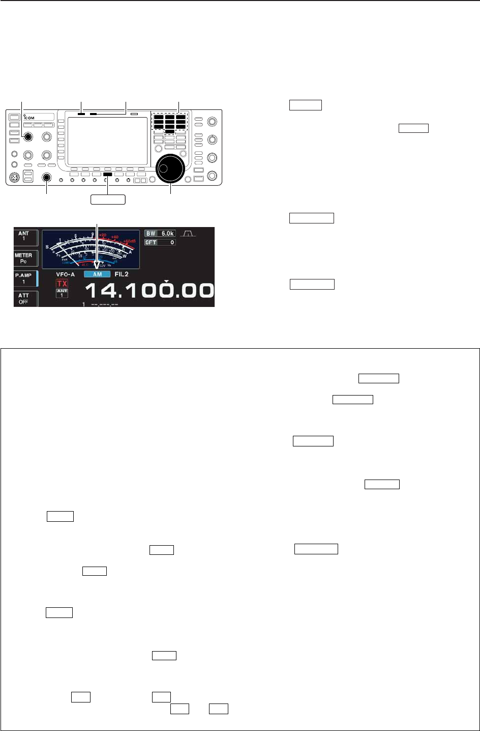
4-29
■Operating AM
qPush a band key to select the desired band.
wPush to select AM.
• “AM” indicator appears.
• After AM mode is selected, push to toggle be-
tween AM and FM modes.
eRotate the main dial to tune to the desired fre-
quency.
• The S-meter indicates received signal strength when
signal is received.
rRotate [AF] to set audio to a comfortable listening
level.
tPush or [PTT] (microphone) to transmit.
• The TX indicator lights red.
ySpeak into the microphone at your normal voice
level.
• Adjust the microphone gain with [MIC] at this step, if
necessary.
uPush or release [PTT] (microphone) to
return to receive.
TRANSMIT
TRANSMIT
AM/FM
AM/FM
Appears
[MIC] [TX] indicator [RX] indicator
[AF] Main dial
Band keys
AM/FM
4
RECEIVE AND TRANSMIT
• Preamp (p. 5-9)
➥Push [P.AMP] (MF3) several times to set the pre-
amp OFF, preamp 1 ON or preamp 2 ON.
• “P.AMP1” or “P.AMP2” appears when the preamp 1 or
preamp 2 is ON.
• Attenuator (p. 5-9)
➥Push [ATT] (MF4) several times to set the attenu-
ator in 6 dB steps.
• Push and hold [ATT] (MF3) for 1 sec. to turn the atten-
uator function OFF.
• “ATT” and attenuation level appear when the attenu-
ator is ON.
• Noise blanker (p. 5-16)
➥Push to turn the noise blanker ON and
OFF, and then rotate [NB] control to adjust the
threshold level.
• Noise blanker indicator (above switch) lights
when the noise blanker is ON.
• Push and hold for 1 sec. to enter noise blanker
set mode.
• Noise reduction (p. 5-17)
➥Push to turn the noise reduction ON and
OFF.
• Rotate [NR] control to adjust the noise reduction
level.
• Noise reduction indicator (above switch) lights
when the noise reduction is ON.
• Audio tone control (p. 12-4)
➥Push [SET] then [LEVEL] to enter level
set mode. Select an item with [Y] /[Z]
then rotate the main dial to adjust the audio tone.
• Twin PBT (passband tuning) (p. 5-12)
➥Rotate [TWIN PBT] controls (inner/outer).
• PBT indicator (above switch) lights when
PBT is in use.
• Push and hold for 1 sec. to clear the set-
tings.
• Notch filter (p. 5-18)
➥Push to turn the manual notch function
ON and OFF.
• Rotate [NOTCH] control to set the attenuating fre-
quency.
• Notch indicator (above switch) lights when
either the auto or manual notch is ON.
• AGC (auto gain control) (p. 5-11)
➥Push [AGC] switch several times to select
AGC FAST, AGC MID or AGC SLOW.
➥Push to turn the AGC time constant
manual setting ON and OFF.
• Rotate [AGC] control to adjust the time constant.
• Auto tuning function (p. 5-19)
➥Push [AUTOTUNE] to turn the auto tuning func-
tion ON and OFF.
• The transceiver automatically tunes the desired sig-
nal within ±5 kHz range.
IMPORTANT!
When receiving a weak signal, or receiving a signal
with interference, the automatic tuning function may
not tune, or may tune to an undesired signal.
AGC VR
NOTCH
NOTCH
PBT-CLR
PBT-CLR
F-2F-1
F-1F-7
NR
NR
NB
NB
NB
D
Convenient functions for receive
4-30
4RECEIVE AND TRANSMIT
• VOX (voice operated transmit) (p. 6-2)
➥Push to turn the VOX function ON and
OFF.
• “ ” appears when the VOX function is ON.
• Transmit quality monitor (p. 6-4)
➥Push to turn the monitor function ON
and OFF.
• Rotate [MONI GAIN] to adjust the monitor gain.
• Monitor indicator (above switch) lights
when the monitor function is ON.
• Audio tone control (p. 12-5)
➥Push [SET] then [LEVEL] to enter level
set mode. Select an item with [Y] /[Z]
then rotate the main dial to adjust the audio tone.
F-2F-1
F-1F-7
MONITOR
MONITOR
VOX
VOX
D
Convenient functions for transmit
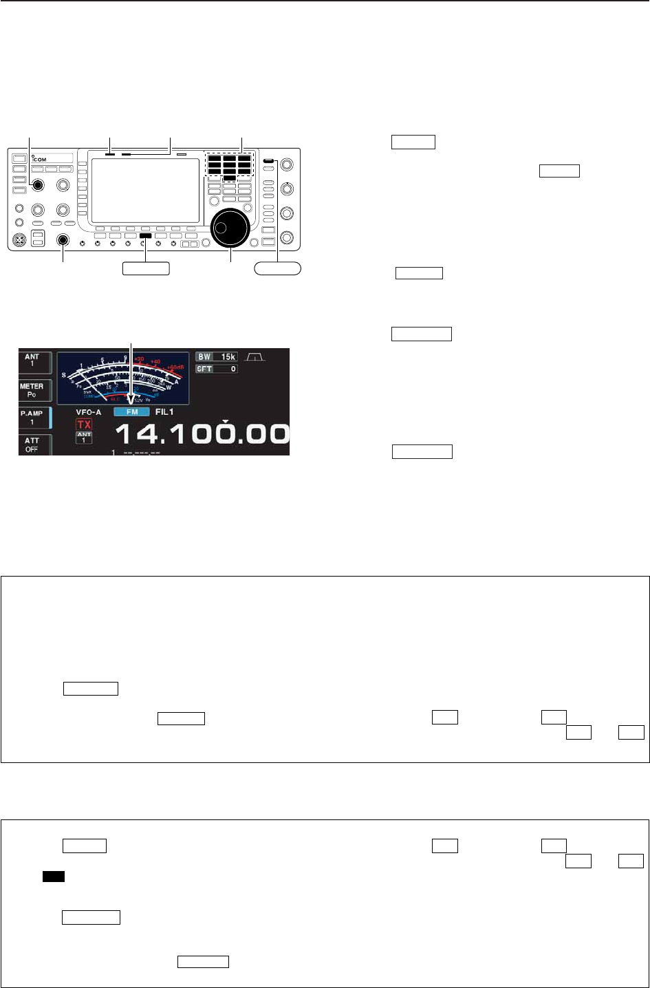
4-31
■Operating FM
qPush a band key to select the desired band.
wPush to select FM.
• “FM” indicator appears.
• After FM mode is selected, push to toggle be-
tween FM and AM modes.
eRotate the main dial to tune to the desired fre-
quency.
• The S-meter indicates received signal strength when
signal is received.
• 10 kHz tuning step is preset for the FM mode.
• Push several times to select the desired filter
width.
rRotate [AF] to set audio to a comfortable listening
level.
tPush or [PTT] (microphone) to transmit.
• The TX indicator lights red.
ySpeak into the microphone at your normal voice
level.
• Adjust the microphone gain with [MIC] at this step, if
necessary.
• FM narrow transmission is available when “FIL2” or
“FIL3” is selected.
uPush or release [PTT] (microphone) to
return to receive.
TRANSMIT
TRANSMIT
FILTER
AM/FM
AM/FM
Appears
[MIC] [TX] indicator [RX] indicator
[AF] Main dial
Band keys
AM/FM FILTER
4
RECEIVE AND TRANSMIT
• Preamp (p. 5-9)
➥Push [P.AMP] (MF3) several times to set the pre-
amp OFF, preamp 1 ON or preamp 2 ON.
• “P.AMP1” or “P.AMP2” appears when the preamp 1 or
preamp 2 is ON.
• Auto notch filter (p. 5-18)
➥Push to turn the auto notch function
ON and OFF.
• Notch indicator (above switch) lights when
the auto notch is ON.
• Attenuator (p. 5-9)
➥Push [ATT] (MF4) several times to set the attenu-
ator in 6 dB steps.
• Push and hold [ATT] (MF4) for 1 sec. to turn the atten-
uator function OFF.
• “ATT” and attenuation level appear when the attenu-
ator is ON.
• Audio tone control (p. 12-4)
➥Push [SET] then [LEVEL] to enter level
set mode. Select an item with [Y] /[Z]
then rotate the main dial to adjust the audio tone.
F-2F-1
F-1F-7
NOTCH
NOTCH
D
Convenient functions for receive
• VOX (voice operated transmit) (p. 6-2)
➥Push to turn the VOX function ON and
OFF.
• “ ” appears when the VOX function is ON.
• Transmit quality monitor (p. 6-4)
➥Push to turn the monitor function ON
and OFF.
• Rotate [MONI GAIN] to adjust the monitor gain.
• Monitor indicator (above switch) lights
when the monitor function is ON.
• Audio tone control (p. 12-5)
➥Push [SET] then [LEVEL] to enter level
set mode. Select an item with [Y] /[Z]
then rotate the main dial to adjust the audio tone.
F-2F-1
F-1F-7
MONITOR
MONITOR
VOX
VOX
D
Convenient functions for transmit
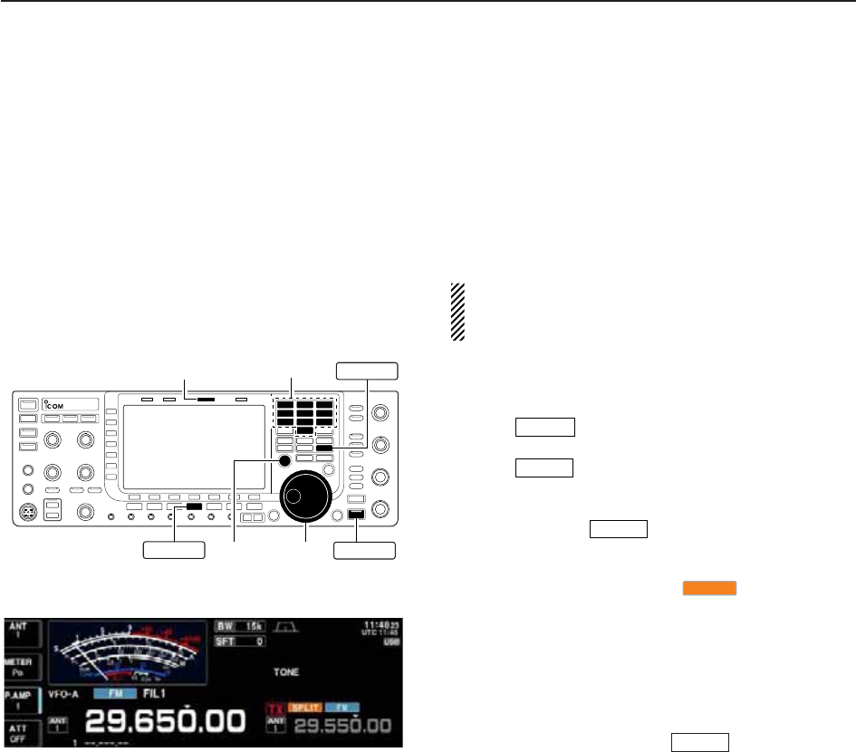
4-32
■Repeater operation
A repeater amplifies received signals and retransmits
them at a different frequency. When using a repeater,
the transmit frequency is shifted from the receive fre-
quency by an offset frequency. A repeater can be ac-
cessed using split frequency operation with the shift
frequency set to the repeater’s receive frequency.
For accessing a repeater which requires a repeater
tone, set the repeater tone frequency in tone fre-
quency set mode as described below.
qSet the offset frequencies (HF, 50 MHz) and turn
ON the quick split function in Others set mode in ad-
vance. (pgs. 12-12, 12-13)
wPush to select VFO mode.
ePush the desired band key.
rPush several times to select FM mode.
tSet the receive frequency (repeater output fre-
quency).
yPush and hold for 1 sec. to start repeater
operation.
• Repeater tone is turned ON automatically.
• [SPLIT] indicator lights and “ ” appears on the
LCD.
• Shifted transmit frequency and “TX” appear in the sub
band.
• The transmit frequency can be monitored while pushing
[XFC].
uPush and hold [PTT] to transmit; release [PTT] to
receive.
iTo return to simplex, push momentarily.
SPLIT
SPLIT
SPLIT
AM/FM
V/M
[SPLIT] indicator
[XFC] Main dial
Band keys V/M
AM/FM SPLIT
4RECEIVE AND TRANSMIT
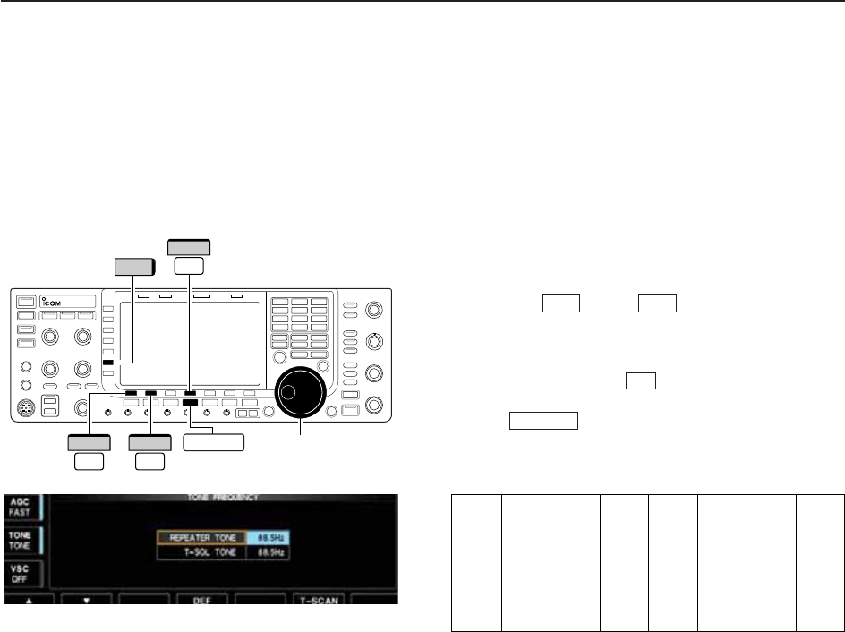
4-33
4
RECEIVE AND TRANSMIT
D
Repeater tone frequency setting
Some repeaters require subaudible tones to be ac-
cessed. Subaudible tones are superimposed on your
normal signal and must be set in advance. The trans-
ceiver has 50 tones from 67.0 Hz to 254.1 Hz.
qSelect FM mode.
wPush and hold [TONE] (MF6) for 1 sec. to tone fre-
quency set mode.
ePush [Y] or [Z] to select REPEATER
TONE item.
rRotate the main dial to select the desired repeater
tone frequency.
• Push and hold [DEF] for 1 sec. to select the de-
fault setting.
tPush to return to the previous indication.
• Available tone frequencies (unit: Hz)
EXIT/SET
F-4
F-2F-1
Main dial
F-4
DEF
TONE
F-1
∫
F-2
√AM/FM
67.0
69.3
71.9
74.4
77.0
79.7
82.5
085.4
088.5
091.5
094.8
097.4
100.0
103.5
107.2
110.9
114.8
118.8
123.0
127.3
131.8
136.5
141.3
146.2
151.4
156.7
159.8
162.2
165.5
167.9
171.3
173.8
177.3
179.9
183.5
186.2
189.9
192.8
196.6
199.5
203.5
206.5
210.7
218.1
225.7
229.1
233.6
241.8
250.3
254.1
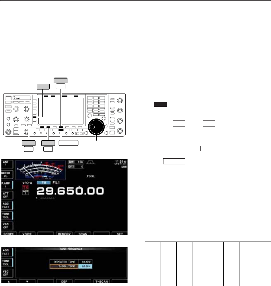
4-34
■Tone squelch operation
The tone squelch opens only when receiving a signal
containing a matching subaudible tone. You can
silently wait for calls from group members using the
same tone.
qSet the desired frequency band and select FM
mode.
wPush [TONE] (MF6) to turn the tone squelch func-
tion ON.
• “ ” appears
ePush and hold [TONE] (MF6) for 1 sec. to tone fre-
quency set mode.
rPush [Y] or [Z] to select T-SQL TONE
item.
tRotate the main dial to select the desired tone
squelch frequency.
• Push and hold [DEF] for 1 sec. to select the de-
fault setting.
yPush to return to the previous indication.
uWhen the received signal includes a matching tone,
squelch opens and the signal can be heard.
• When the received signal’s tone does not match, tone
squelch does not open. However, the S-indicator shows
signal strength.
• To open the squelch manually, push [XFC].
iOperate the transceiver in the normal way.
oTo cancel the tone squelch, push [TONE] (MF6) to
clear “TSQL.”
• Available tone frequencies (unit: Hz)
EXIT/SET
F-4
F-2F-1
TSQL
Main dial
F-4
DEF
TONE
F-1
∫
F-2
√AM/FM
4RECEIVE AND TRANSMIT
67.0
69.3
71.9
74.4
77.0
79.7
82.5
085.4
088.5
091.5
094.8
097.4
100.0
103.5
107.2
110.9
114.8
118.8
123.0
127.3
131.8
136.5
141.3
146.2
151.4
156.7
159.8
162.2
165.5
167.9
171.3
173.8
177.3
179.9
183.5
186.2
189.9
192.8
196.6
199.5
203.5
206.5
210.7
218.1
225.7
229.1
233.6
241.8
250.3
254.1
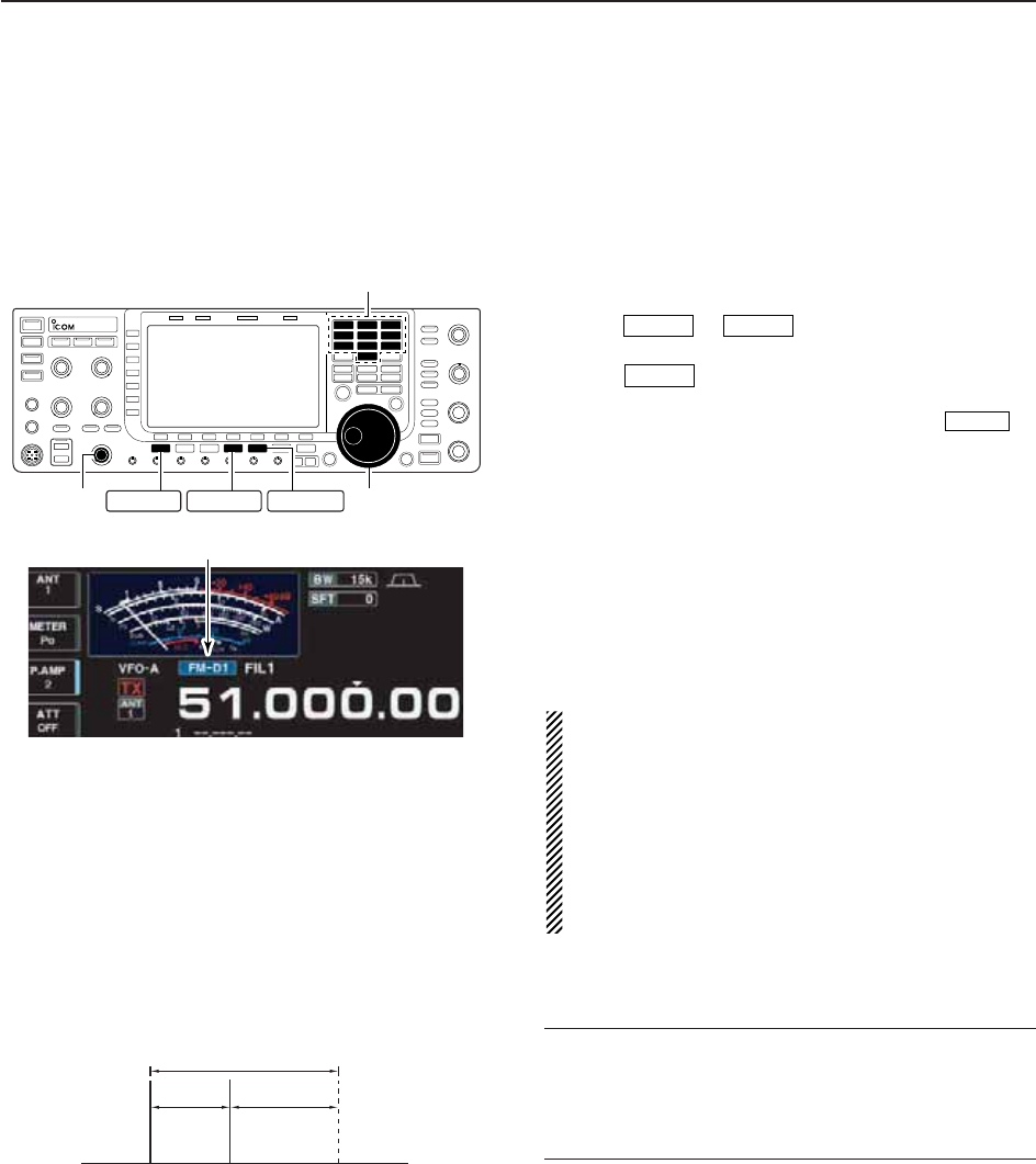
4-35
4
RECEIVE AND TRANSMIT
■Data mode (AFSK) operation
When operating AMTOR or PACKET with your TNC
and/or PC software, consult the manual that comes
with the TNC and/or the software.
qConnect a PC and TNC to the transceiver. (p. 2-9)
wPush a band key to select the desired band.
ePush or to select the desired oper-
ating mode.
rPush to turn data mode ON.
• One of “-D1,” “-D2” or “-D3” is additionally appears.
• During data mode selection, push and hold for
1 sec. to select data mode 1 (D1), 2 (D2) and 3 (D3) in
sequence.
tRotate the main dial to tune to the desired signal
and decode it correctly.
• Also use the tuning indicator of the TNC or software.
• During SSB data mode, 1⁄4tuning function can be used
for critical tuning.
yOperate the PC (software) or TNC to transmit.
• When operating in SSB data mode, adjust the TNC out-
put level so that the ALC meter reading doesn’t go out-
side the ALC zone.
NOTE: When SSB data mode is selected, the audio
input from the [ACC1 (pin 6)] is used for transmis-
sion instead of [MIC]’s. (Modulation input connector can
be changed in ACC set mode. (pgs. 12-7, 12-8))
The fixed condition is used for SSB data transmis-
sion as follows:
• [COMP] : OFF
• Tx bandwidth : MID
• Tx Tone (Bass) : 0
• Tx Tone (Trebles): 0
✔
For your information
Carrier frequency is displayed when SSB data mode
is selected.
See the diagram left for the tone-pair example.
DATA
DATA
AM/FMSSB
200 Hz 2125 Hz
2325 Hz
Carrier frequency
(displayed frequency)
Appears
Main dial
Band keys
[AF] AM/FM DATASSB
• Tone-pair example

5-1
FUNCTIONS FOR RECEIVE Section 5
■Spectrum scope screen ……………………………………………… 5-2
DCenter mode ………………………………………………………… 5-2
DFixed mode …………………………………………………………… 5-3
DMini scope screen indication ……………………………………… 5-4
DScope set mode ……………………………………………………… 5-4
■Preamplifier ……………………………………………………………… 5-9
■Attenuator ……………………………………………………………… 5-9
■RIT function …………………………………………………………… 5-10
DRIT monitor function …………………………………………………5-10
■AGC function …………………………………………………………… 5-11
DSelecting the preset value …………………………………………5-11
DAdjusting the AGC time constant …………………………………5-11
DSetting the AGC time constant preset value ………………………5-11
■Twin PBT operation …………………………………………………… 5-12
■IF filter selection ……………………………………………………… 5-13
DIF filter selection …………………………………………………… 5-13
DFilter passband width setting (except FM mode) ……………… 5-13
DRoofing filter selection ……………………………………………… 5-14
DDSP filter shape …………………………………………………… 5-14
DFilter shape set mode ……………………………………………… 5-14
■Noise blanker ………………………………………………………… 5-16
DNB set mode ………………………………………………………… 5-16
■Noise reduction ………………………………………………………… 5-17
■Dial lock function ……………………………………………………… 5-17
■Notch function ………………………………………………………… 5-18
■Digital selector ………………………………………………………… 5-18
■Autotune function ……………………………………………………… 5-19
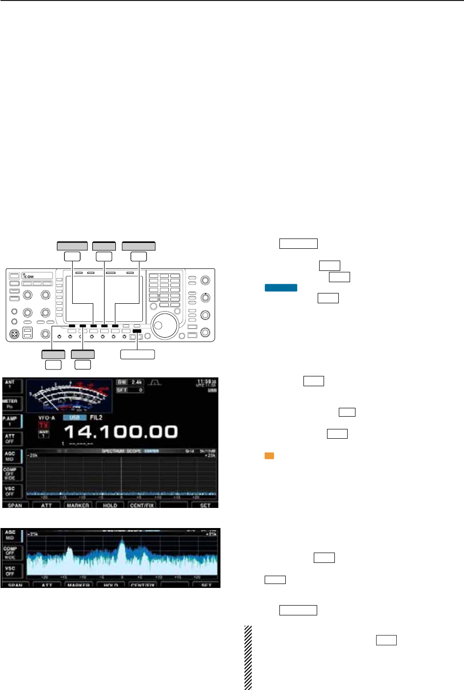
5-2
■Spectrum scope screen
This DSP-based spectrum scope allows you to display
the conditions on the selected band, as well as relative
strengths of signals. The IC-7700 has two modes for
the spectrum indication— one is center mode, and an-
ther one is fixed mode.
In addition, the IC-7700 has a mini scope screen to
save screen space.
D
Center mode
Displays signals around the set frequency within the
selected span. The set frequency is always displayed
at the center of the screen.
qPush several times to close a multi-func-
tion screen, if necessary.
wPush [SCOPE] to select the scope screen.
ePush [CENT/FIX] to select the center mode.
• “ ” is displayed when center mode is selected.
rPush [SPAN] several times to select the
scope span.
• ±2.5, ±5.0, ±10, ±25, ±50, ±100 and ±250 kHz are avail-
able.
• Push and hold [F-1•SPAN] for 1 sec. to return to ±2.5
kHz span.
• Sweeping speed is selectable for each span indepen-
dently in scope set mode. (pgs. 5-5, 5-6)
tPush [ATT] several times to activate an atten-
uator or turn the attenuator OFF.
• 10, 20 and 30 dB attenuators are available.
• Push and hold [ATT] for 1 sec. to turn OFF the at-
tenuator.
yPush [MARKER] to turn the marker for trans-
mit frequency ON or OFF.
• “ ” displays the marker at the transmit frequency.
• “<<” or “>>” appears when the marker is out of range.
• The spectrum scope shows the transmit signal wave-
form while transmitting. This can be deactivated in
scope set mode. (p. 5-5)
• The spectrum scope shows the peak level holding func-
tion. Peak levels are displayed in the background of the
current spectrum in a different color until the receive fre-
quency changes. This can be deactivated and the wave-
form color can be set in scope set mode. (p. 5-5)
uPush [HOLD] to freeze the current spectrum
waveform.
• “ ” appears while the function is in use.
• The peak hold function can be deactivated in scope set
mode.
iPush to exit the scope screen.
NOTE: If a strong signal is received, a ghost wave-
form may appear. Push [ATT] several times to
activate the spectrum scope attenuator in this case.
Spurious signal waveforms may be displayed. They
are generated in the internal scope circuit and do
not indicate a transceiver malfunction.
F-2
EXIT/SET
HOLD
F-4
T
F-3
F-2
F-2
F-1
CENTER
F-5
F-1
EXIT/SET
F-2
ATT
F-4
HOLD
F-1
SPAN
F-3
MARKER
F-5
CENT/FIX
EXIT/SET
5FUNCTIONS FOR RECEIVE
• Observed indication example
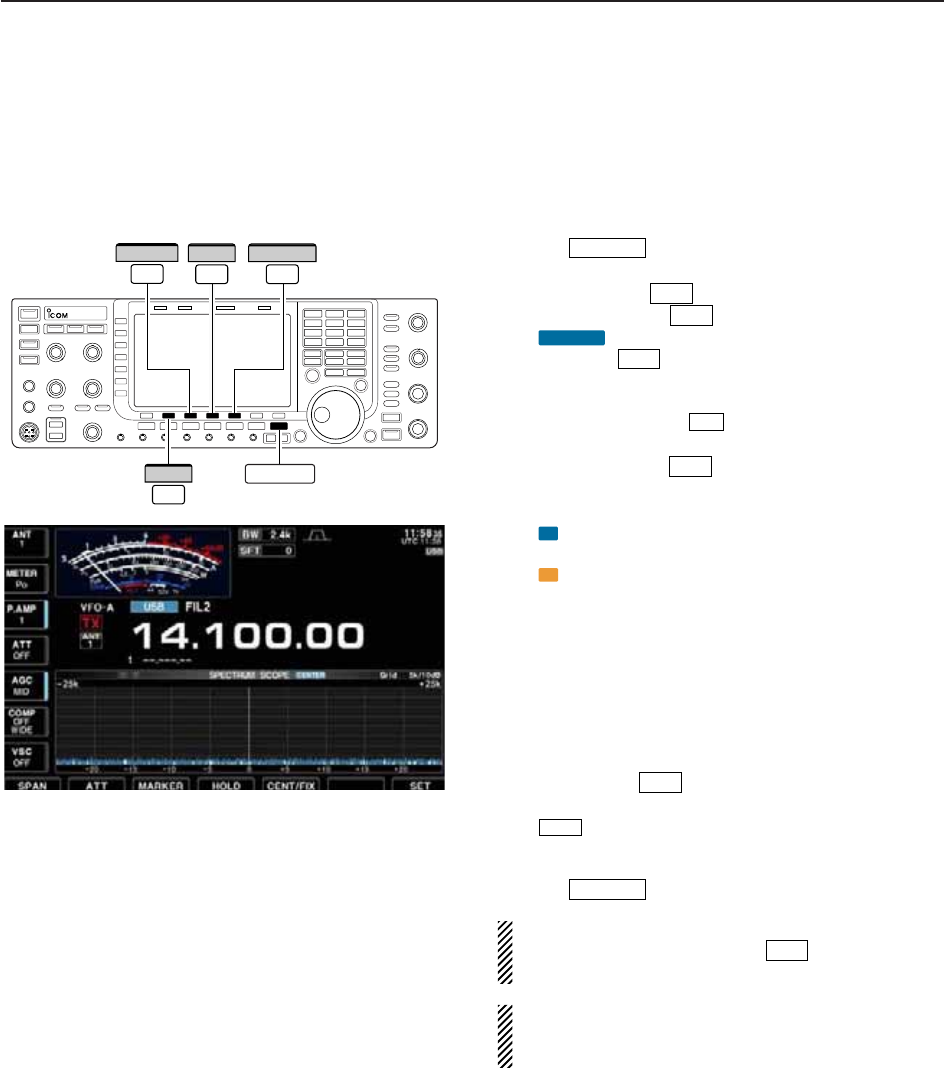
5-3
D
Fixed mode
Displays signals within the specified frequency range.
The selected frequency band conditions can be ob-
served at a glance when using this mode.
qPush several times to close a multi-func-
tion screen, if necessary.
wPush [SCOPE] to select the scope screen.
ePush [CENT/FIX] to select the fixed mode.
• “ ” is displayed when fixed mode is selected.
rPush [ATT] several times to activate an atten-
uator or turn the attenuator OFF.
• 10, 20 and 30 dB attenuators are available.
• Push and hold [ATT] for 1 sec. to turn OFF the at-
tenuator.
tPush [MARKER] several times to select the
marker for transmit frequency or turn the marker
OFF.
• “ ” displays the marker at the receive frequency. (al-
ways displayed)
• “ ” displays the marker at the transmit frequency.
• “<<” or “>>” appears when the marker is out of range.
• The spectrum scope shows the transmit signal wave-
form while transmitting. This can be deactivated in
scope set mode. (p. 5-5)
• The spectrum scope shows the peak level holding func-
tion. Peak levels are displayed in the background of the
current spectrum in a different color until the receive fre-
quency changes. This can be deactivated and the wave-
form color can be set in scope set mode. (p. 5-5)
yPush [HOLD] to freeze the current spectrum
waveform.
• “ ” appears while the function is in use.
• The peak hold function can be deactivated in scope set
mode.
uPush to exit the scope screen.
NOTE: If a strong signal is received, a ghost wave-
form may appear. Push [ATT] several times to
activate the spectrum scope attenuator in this case.
The scope bandwidth can be specified for each op-
erating frequency band independently in scope set
mode. (pgs. 5-6 to 5-8)
F-2
EXIT/SET
HOLD
F-4
T
R
F-3
F-2
F-2
FIX
F-5
F-1
EXIT/SET
F-4
HOLD
F-5
CENT/FIX
EXIT/SET
F-2
ATT
F-3
MARKER
5
FUNCTIONS FOR RECEIVE
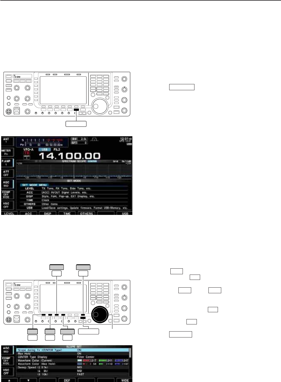
5-4
D
Mini scope screen indication
The mini scope screen can be displayed with another
screen display, such as set mode menu, decode
screen, memory list screen, etc. simultaneously.
qSet the scope mode (center or fixed), marker, at-
tenuator, span, etc. in advance. (pgs. 5-2, 5-3)
wPush to toggle the mini scope indication
ON and OFF.
• The S/RF meter type during mini scope indication can
be selected in display set mode (Meter Type (Wide
Screen) item). (p. 12-10)
D
Scope set mode
This set mode is used to set the waveform color,
sweeping speed, scope range for fixed mode, etc.
qDuring spectrum scope display ON, push
[SET] to select scope set mode screen.
• Push [WIDE] to toggle the screen size between
normal and wide.
wPush [Y] or [Z] to select the desired set
item.
eSet the desired condition using the main dial.
• Push and hold [DEF] for 1 sec. to select the de-
fault condition or value.
• Push [Ω≈] to select the set contents for some
items.
rPush to exit from set mode.
EXIT/SET
F-3
F-4
F-2F-1
F-7
F-7
M.SCOPE
F-3 F-7
WIDE
Ω ≈
Main dial
EXIT/SET
DEF
F-1
∫
F-2
√
F-4
M.SCOPE
5FUNCTIONS FOR RECEIVE
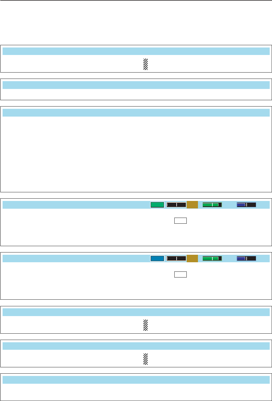
5-5
D
Scope set mode (continued)
5
FUNCTIONS FOR RECEIVE
Turn the transmitting signal waveform indication ON
and OFF.
NOTE: The transmitting signal waveform indica-
tion is available for the center mode only.
Scope during Tx (CENTER Type)
ON
Turn the peak level holding function ON and OFF.
Max Hold
ON
Select the center frequency of the spectrum scope
indication (center mode only).
• Filter center : Shows the selected filter’s center
frequency at the center.
• Carrier Point Center
: Shows the selected operating
mode carrier point frequency at
the center.
• Carrier Point Center (Abs. Freq.)
: In addition to the carrier point
center setting above, the actual
frequency is displayed for the
bottom of the scope.
CENTER Type Display
Filter Center
Set the waveform color for the currently received sig-
nals.
• The color is set in RGB format.
• Push [Ω≈] to select R (Red), G (Green) and B
(Blue), and rotate the ratio from 0 to 255 range.
• The set color is indicated in the box beside the RGB
scale.
F-3
Waveform Color (Current)
0204 102
Set the waveform color for the receiving signals max-
imum level.
• The color is set in RGB format.
• Push [Ω≈] to select R (Red), G (Green) and B
(Blue), and rotate the ratio from 0 to 255 range.
• The set color is indicated in the box beside the RGB
scale.
F-3
Waveform Color (Max Hold)
0102 153
Select the sweep speed for the ±2.5 kHz span selec-
tion from SLOW, MID and FAST.
NOTE: The waveform may be displayed incorrect-
ly with “FAST” setting.
Sweep Speed (± 2.5k)
MID
Select the sweep speed for the ±5 kHz span selec-
tion from SLOW, MID and FAST.
NOTE: The waveform may be displayed incorrect-
ly with “FAST” setting.
(± 5k)
MID
Select the sweep speed for the ±10 kHz span selec-
tion from SLOW, MID and FAST.
(± 10k)
FAST

5-6
D
Scope set mode (continued)
5FUNCTIONS FOR RECEIVE
Select the sweep speed for the ±50 kHz span selec-
tion from SLOW, MID and FAST.
(± 50k)
FAST
Select the sweep speed for the ±100 kHz span selec-
tion from SLOW, MID and FAST.
(± 100k)
FAST
Select the sweep speed for the ±250 kHz span selec-
tion from SLOW, MID and FAST.
(± 250k)
FAST
Set the scope edge frequencies for fixed mode for
bands below 1.6 MHz.
• Set the frequencies within 0.030 to 1.600 MHz
range in 1 kHz steps.
Up to 500 kHz band width can be specified, so
either edge frequency will be set to the difference
between higher and lower frequencies from 5 to
500 kHz automatically while setting another edge
frequency.
Fixed Edges ( 0.03 – 1.60)
0.750 1.250– MHz
Set the scope edge frequencies for fixed mode scope
when the 1.6 to 2 MHz band is selected.
• Set the frequencies within 1.600 to 2.000 MHz
range in 1 kHz steps.
( 1.60 – 2.00)
1.800 2.000– MHz
Set the scope edge frequencies for fixed mode scope
when the 2 to 6 MHz band is selected.
• Set the frequencies within 2.000 to 6.000 MHz
range in 1 kHz steps.
Up to 500 kHz band width can be specified, so
either edge frequency will be set to the difference
between higher and lower frequencies from 5 to
500 kHz automatically while setting another edge
frequency.
( 2.00 – 6.00)
3.500 4.000– MHz
Set the scope edge frequencies for fixed mode scope
when the 6 to 8 MHz band is selected.
• Set the frequencies within 6.000 to 8.000 MHz
range in 1 kHz steps.
Up to 500 kHz band width can be specified, so
either edge frequency will be set to the difference
between higher and lower frequencies from 5 to
500 kHz automatically while setting another edge
frequency.
( 6.00 – 8.00)
7.000 7.300– MHz
Select the sweep speed for the ±25 kHz span selec-
tion from SLOW, MID and FAST.
(± 25k)
FAST

5-7
D
Scope set mode (continued)
5
FUNCTIONS FOR RECEIVE
Set the scope edge frequencies for fixed mode scope
when the 8 to 11 MHz band is selected.
• Set the frequencies within 8.000 to 11.000 MHz
range in 1 kHz steps.
Up to 500 kHz band width can be specified, so
either edge frequency will be set to the difference
between higher and lower frequencies from 5 to
500 kHz automatically while setting another edge
frequency.
( 8.00 – 11.00)
10.100 10.150– MHz
Set the scope edge frequencies for fixed mode scope
when the 11 to 15 MHz band is selected.
• Set the frequencies within 11.000 to 15.000 MHz
range in 1 kHz steps.
Up to 500 kHz band width can be specified, so
either edge frequency will be set to the difference
between higher and lower frequencies from 5 to
500 kHz automatically while setting another edge
frequency.
(11.00 – 15.00)
14.000 14.350– MHz
Set the scope edge frequencies for fixed mode scope
when the 15 to 20 MHz band is selected.
• Set the frequencies within 15.000 to 20.000 MHz
range in 1 kHz steps.
Up to 500 kHz band width can be specified, so
either edge frequency will be set to the differ-
ence between higher and lower frequencies from
5 to 500 kHz automatically while setting another
edge frequency.
(15.00 – 20.00)
18.068 18.168– MHz
Set the scope edge frequencies for fixed mode scope
when the 20 to 22 MHz band is selected.
• Set the frequencies within 20.000 to 22.000 MHz
range in 1 kHz steps.
Up to 500 kHz band width can be specified, so
either edge frequency will be set to the difference
between higher and lower frequencies become 5
to 500 kHz automatically while setting another
edge frequency.
(20.00 – 22.00)
21.000 21.450– MHz
Set the scope edge frequencies for fixed mode scope
when the 22 to 26 MHz band is selected.
• Set the frequencies within 22.000 to 26.000 MHz
range in 1 kHz steps.
Up to 500 kHz band width can be specified, so
either edge frequency will be set to the difference
between higher and lower frequencies from 5 to
500 kHz automatically while setting another edge
frequency.
(22.00 – 26.00)
24.890 24.990– MHz

5-8
D
Scope set mode (continued)
5FUNCTIONS FOR RECEIVE
Set the scope edge frequencies for fixed mode scope
when the 30 to 45 MHz band is selected.
• Set the frequencies within 30.000 to 45.000 MHz
range in 1 kHz steps.
Up to 500 kHz band width can be specified, so
either edge frequency will be set to the difference
between higher and lower frequencies from 5 to
500 kHz automatically while setting another edge
frequency.
(30.00 – 45.00)
30.000 30.500– MHz
Set the scope edge frequencies for fixed mode scope
when the 45 to 60 MHz band is selected.
• Set the frequencies within 45.000 to 60.000 MHz
range in 1 kHz steps.
Up to 500 kHz band width can be specified, so
either edge frequency will be set to the difference
between higher and lower frequencies from 5 to
500 kHz automatically while setting another edge
frequency.
(45.00 – 60.00)
50.000 50.500– MHz
Set the scope edge frequencies for fixed mode scope
when the 26 to 30 MHz band is selected.
• Set the frequencies within 26.000 to 30.000 MHz
range in 1 kHz steps.
Up to 500 kHz band width can be specified, so
either edge frequency will be set to the difference
between higher and lower frequencies from 5 to
500 kHz automatically while setting another edge
frequency.
(26.00 – 30.00)
28.000 28.500– MHz
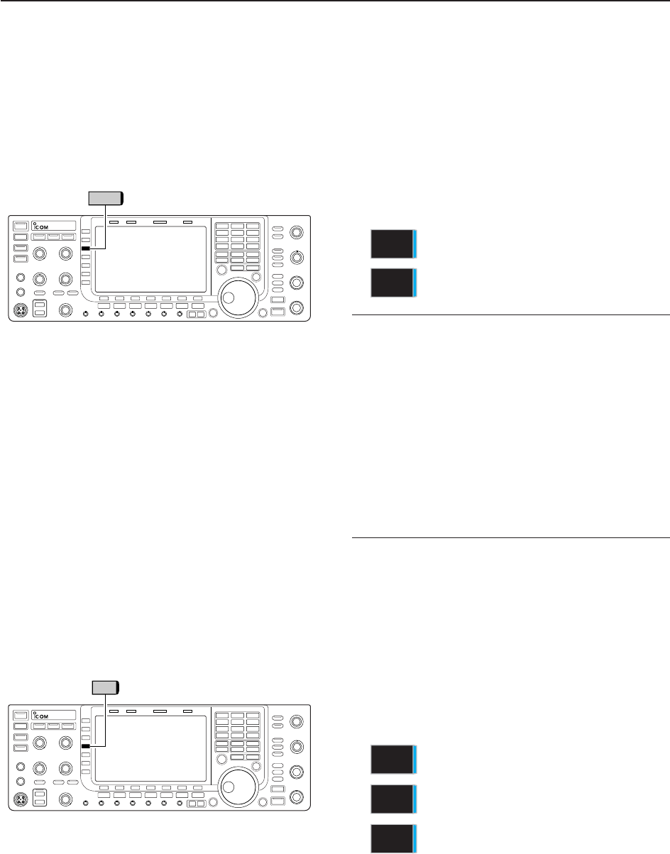
5-9
■Preamplifier
The preamp amplifies received signals in the receiver
front end, to improve the S/N ratio and sensitivity. Set
this to preamp 1 or preamp 2 when receiving weak sig-
nals.
➥Push [P.AMP] (MF3) several times to set the preamp
OFF, preamp 1 ON or preamp 2 ON.
For all HF bands
High-gain preamp for 24 MHz band and
above
✔
About the “P.AMP2”
The “P.AMP 2” is a high gain receive amplifier. When
the “P.AMP 2” is used in the presence of strong elec-
tromagnetic fields, distortion sometimes results. In
such cases, use the transceiver with the “P.AMP 1” or
“P.AMP OFF” setting.
The “P.AMP 2” is most effective when:
• Used on bands above 24 MHz and when signals are
weak.
• Receive sensitivity is insufficient when using low-gain
antennas, or while using a narrow band antenna
(such as small loop, a Beverage antenna or a short
Yagi antenna).
■Attenuator
The attenuator prevents a desired signal from distor-
tion when very strong signals are near the desired fre-
quency or when very strong electromagnetic fields,
such as from broadcasting stations near your location.
➥Push [ATT] (MF4) several times to set the attenuator
6 dB, 12 dB, 18 dB or attenuator OFF.
➥Push and hold [ATT] (MF4) for 1 sec. to turn the at-
tenuator function OFF.
P.AMP
2
P.AMP
1
P.AMP
ATT
5
FUNCTIONS FOR RECEIVE
6dB
attenuation
12 dB
attenuation
18 dB
attenuation
ATT
18dB
ATT
12dB
ATT
6dB
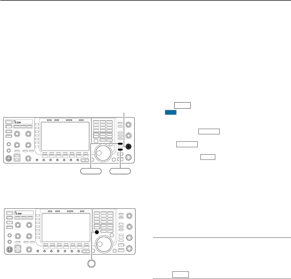
5-10
■RIT function
The RIT (Receive Increment Tuning) function com-
pensates for off-frequency operation of the received
station.
The function shifts the receive frequency up to
±9.99 kHz in 10 Hz steps without moving the transmit
frequency.
qPush to turn the RIT function ON and OFF.
• “ ” and the shifting frequency appear when the func-
tion is ON.
wRotate the [RIT/∂TX] control.
• Push and hold for 1 sec. to reset the RIT fre-
quency.
• Push momentarily to reset the RIT frequency
when the quick RIT/∂TX clear function is ON. (p. 12-15)
• Push and hold for 1 sec. to add the shift fre-
quency to the operating frequency.
D
RIT monitor function
When the RIT function is ON, pushing and holding
[XFC] allows you to monitor the operating frequency
directly (RIT is temporarily cancelled).
✔
For your convenience— Calculate function
The shift frequency of the RIT function can be
added/subtracted to the displayed frequency.
➥While displaying the RIT shift frequency, push and
hold for 1 sec.
RIT
RIT
CLEAR
CLEAR
RIT
RIT
[RIT/∂TX]
RIT CLEAR
XFC
5FUNCTIONS FOR RECEIVE
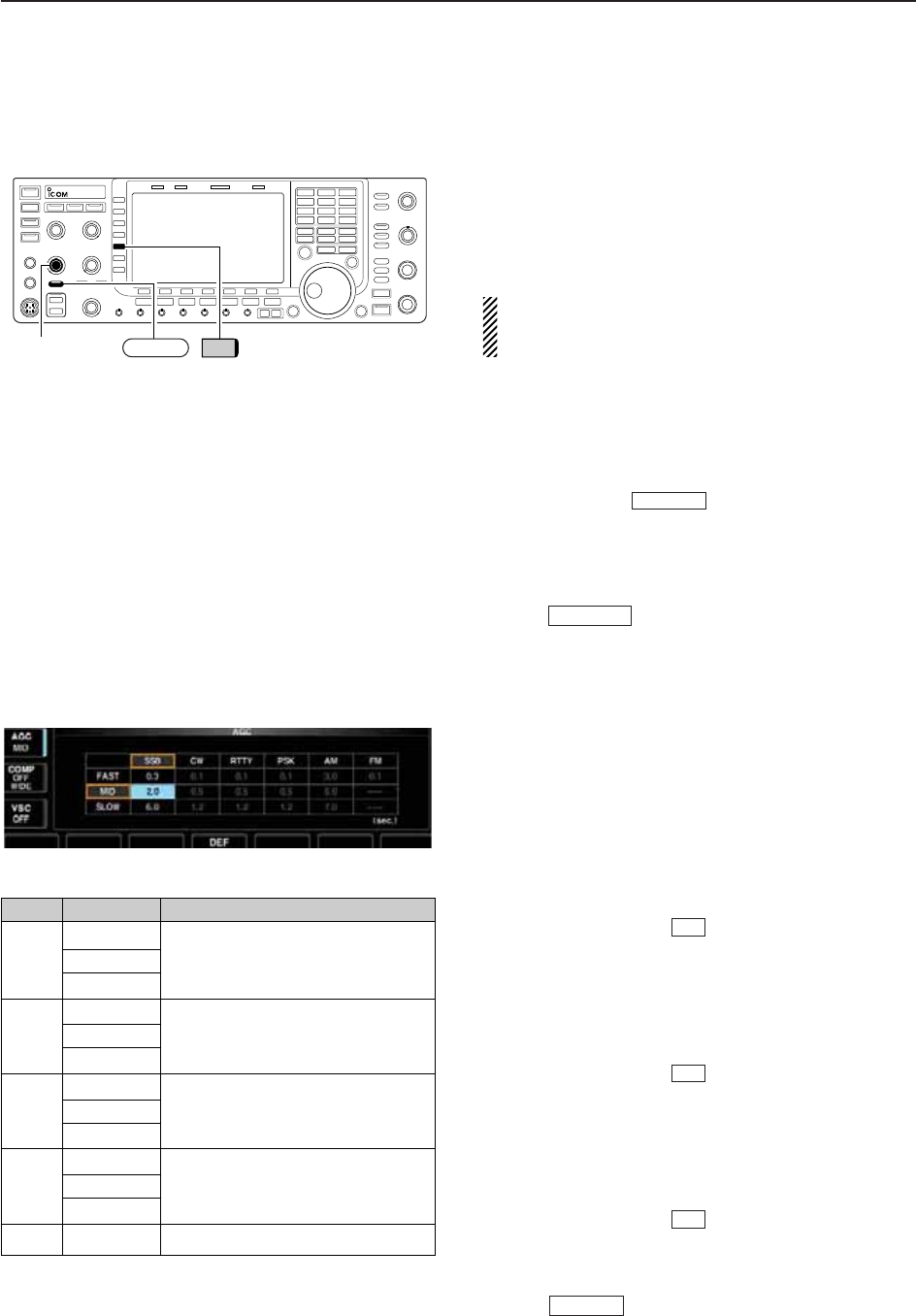
5-11
■AGC function
The AGC (auto gain control) controls receiver gain to
produce a constant audio output level even when the
received signal strength varies greatly.
The transceiver has 3 preset AGC characteristics (time
constant: fast, mid, slow) for non-FM mode.
The FM mode AGC time constant is fixed as ‘FAST’
(0.1 sec.) and AGC time constant cannot be
changed.
D
Selecting the preset value
qSelect any non-FM mode.
wPush [AGC] (MF5) several times to select AGC fast,
AGC medium (MID) or AGC slow.
• Push and hold for 1 sec. to turn the AGC
function OFF.
D
Adjusting the AGC time constant
qSelect any non-FM mode.
wPush , then rotate [AGC] control to adjust
the AGC time constant.
• [AGC VR] indicator above the switch lights green.
D
Setting the AGC time constant preset value
qSelect any non-FM mode.
wPush and hold [AGC] (MF5) for 1 sec. to enter AGC
set mode.
ePush [AGC] (MF5) several times to select FAST time
constant.
rRotate the main dial to set the desired time constant
for ‘AGC FAST.’
• AGC time constant can be set between 0.1 to 8.0 sec.
(depends on mode) or turned OFF.
• Push and hold [DEF] for 1 sec. to select a default
value.
tPush [AGC] (MF5) to select medium time constant.
yRotate the main dial to set the desired time constant
for ‘AGC MID.’
• AGC time constant can be set between 0.1 to 8.0 sec.
(depends on mode) or turned OFF.
• Push and hold [DEF] for 1 sec. to select a default
value.
uPush [AGC] (MF5) to select slow time constant.
iRotate the main dial to set the desired time constant
for ‘AGC SLOW.’
• AGC time constant can be set between 0.1 to 8.0 sec.
(depends on mode) or turned OFF.
• Push and hold [DEF] for 1 sec. to select a default
value.
oSelect another non-FM mode. Repeat steps eto i
if desired.
!0 Push to exit the AGC set mode screen.
EXIT/SET
F-4
F-4
F-4
AGC VR
AGC VR
[AGC] control AGC VR AGC
5
FUNCTIONS FOR RECEIVE
Mode Default Selectable AGC time constant
0.3 (FAST) 0.1, 0.2, 0.3, 0.5, 0.8, 1.2, 1.6, 2.0,
SSB 2.0 (MID) 2.5, 3.0, 4.0, 5.0, 6.0
6.0 (SLOW)
0.1 (FAST) 0.1, 0.2, 0.3, 0.5, 0.8, 1.2, 1.6, 2.0,
CW 0.5 (MID) 2.5, 3.0, 4.0, 5.0, 6.0
1.2 (SLOW)
RTTY 0.1 (FAST) 0.1, 0.2, 0.3, 0.5, 0.8, 1.2, 1.6, 2.0,
PSK 0.5 (MID) 2.5, 3.0, 4.0, 5.0, 6.0
1.2 (SLOW)
3.0 (FAST) 0.3, 0.5, 0.8, 1.2, 1.6, 2.0, 2.5, 3.0,
AM 5.0 (MID) 4.0, 5.0, 6.0, 7.0, 8.0
7.0 (SLOW)
FM 0.1 (FAST) Fixed
• Selectable AGC time constant (unit: sec.)
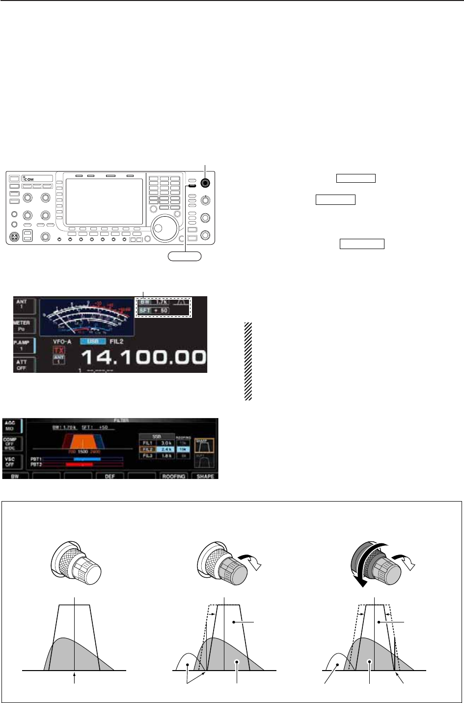
5-12
■Twin PBT operation
PBT (Passband Tuning) electronically narrows the IF
passband width by shifting the IF frequency slightly
outside of the IF filter passband to reject interference.
The IC-7700 uses DSP for the PBT function. Moving
both [TWIN-PBT] controls to the same position shifts
the IF for both high and low frequencies.
➥The LCD shows the passband width and shift fre-
quency graphically.
• PBT indicator above switch lights when PBT
is in use.
➥Push and hold for 1 sec. to enter the filter
set screen. Current passband width and shift fre-
quency is displayed in the filter set screen.
➥To set the [TWIN-PBT] controls to the center posi-
tions, push and hold for 1 sec.
The variable range depends on the passband width
and mode. The edge of the variable range is half of the
passband width, and PBT is adjustable in 25
(SSB/CW/RTTY/PSK modes) or 100 Hz (AM mode)
steps.
• [TWIN-PBT] should normally be set to the center posi-
tions (PBT setting is cleared) when there is no interfer-
ence.
• When PBT is used, the audio tone may be changed.
• Not available for FM mode.
• While rotating [TWIN-PBT], noise may occur. This comes
from the DSP unit and does not indicate an equipment
malfunction.
• Filter set screen
• PBT operation example
PBT-CLR
FILTER
PBT-CLR
[TWIN-PBT]
PBT-CLR
Shows filter width, shifting value and condition
IF center frequency Interference Desired signal
Passband
Both controls at
center position
Cutting a lower
passband
Cutting both higher and
lower passbands
Interference InterferenceDesired signal
Passband
PBT1
PBT2
PBT1
PBT2
PBT1
PBT2
5FUNCTIONS FOR RECEIVE
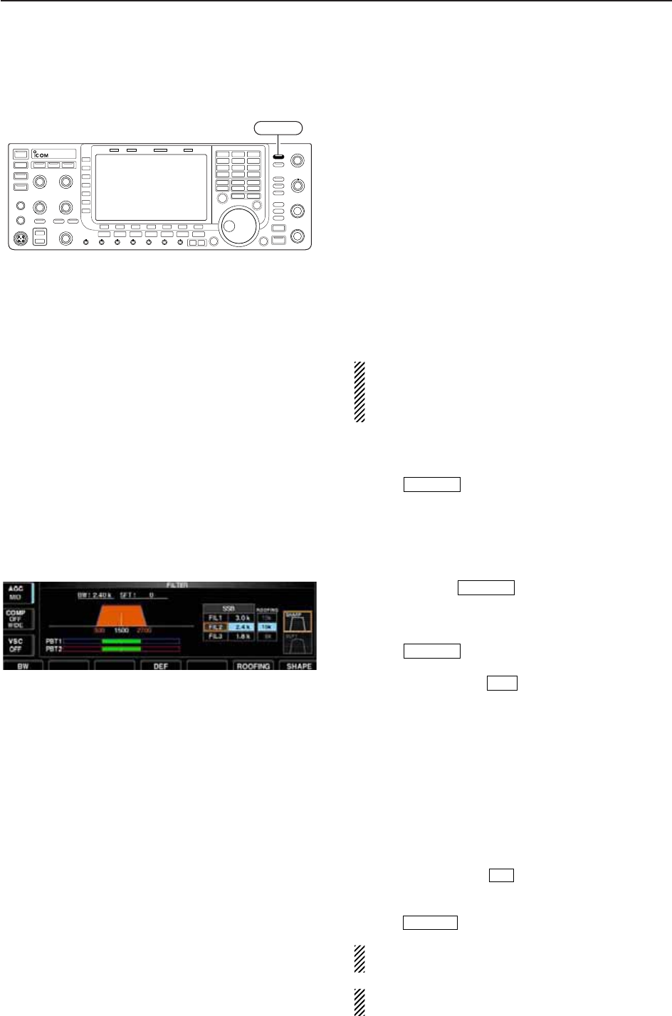
5-13
■IF filter selection
The transceiver has 3 passband width IF filters for
each mode.
For SSB, CW and PSK modes, the passband width
can be set within 50 to 3600 Hz in 50 or 100 Hz steps.
A total of 41 passband widths are available.
For RTTY mode, the passband width can be set within
50 to 2700 Hz in 50 or 100 Hz steps. A total of 32 pass-
band widths are available.
For AM mode, the passband width can be set within
200 Hz to 10 kHz in 200 Hz steps. A total of 50 pass-
band widths are available.
For FM mode, the passband width is fixed and 3 pass-
band widths are available.
The filter selection is automatically memorized in
each mode.
The PBT shift frequencies are automatically memo-
rized in each filter.
D
IF filter selection
qSelect the desired mode.
wPush several times to select the IF filter
1, 2 or 3.
• The selected passband width and filter number is dis-
played in the LCD.
D
Filter passband width setting (except FM mode)
qPush and hold for 1 sec. to enter filter set
screen.
wSelect any mode except FM.
• Passband widths for FM modes are fixed and cannot be set.
ePush several times to select the desired
IF filter.
rWhile pushing [BW] , rotate the main dial to set
the desired passband width.
• In SSB, CW and PSK modes, the passband width can
be set within the following range.
50 to 500 Hz 50 Hz steps
600 to 3600 Hz 100 Hz steps
• In RTTY mode, the passband width can be set within the
following range.
50 to 500 Hz 50 Hz steps
600 to 2700 Hz 100 Hz steps
• In AM mode, the passband width can be set within the
following range.
200 Hz to 10 kHz 200 Hz steps
• Push and hold [DEF] for 1 sec. to select the default
value.
tRepeat steps wto rif desired for other modes.
yPush to exit filter set screen.
The PBT shift frequencies are cleared when the
passband width is changed.
This filter set screen graphically displays the PBT
shift frequencies and CW pitch operations.
EXIT/SET
F-4
F-1
FILTER
FILTER
FILTER
FILTER
5
FUNCTIONS FOR RECEIVE
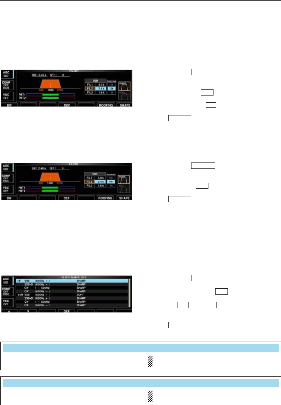
5-14
D
Roofing filter selection
The IC-7700 has 3, 6 and 15 kHz roofing filters at the
1st IF frequency. The roofing filter provides interfer-
ence reduction from nearby strong signals.
qPush and hold for 1 sec. to enter filter set
screen.
wSelect any mode except FM.
ePush [ROOFING] to select the desired filter
width from 15 kHz (default), 6 kHz and 3 kHz.
• Push and hold [DEF] for 1 sec. to select a default
value.
rPush to exit filter set screen.
D
DSP filter shape
The type of DSP filter shape for each SSB, SSB data
and CW can be selected independently from soft and
sharp.
qPush and hold for 1 sec. to enter filter set
screen.
wSelect SSB, SSB data or CW mode.
ePush [SHAPE] to select the desired filter
shape from soft and sharp.
rPush to exit filter set screen.
The filter shape can be set for each band (HF and
50 MHz bands), mode, as well as the passband width
setting (CW only) independently from your default set-
ting in filter shape set mode.
D
Filter shape set mode
The type of DSP filter shape for SSB, SSB data and
CW can be selected independently from soft and
sharp.
qPush and hold for 1 sec. to enter filter set
screen.
wPush and hold [SHAPE] for 1 sec. to enter fil-
ter shape set mode.
ePush [Y] or [Z] to select the desired item.
rRotate the main dial to select the filter shape from
soft and sharp.
tPush to exit filter shape set mode.
EXIT/SET
F-2F-1
F-7
FILTER
EXIT/SET
F-7
FILTER
EXIT/SET
F-4
F-6
FILTER
5FUNCTIONS FOR RECEIVE
Select the filter shape for SSB mode in HF bands. The set filter shape is automatically used only
when the IF filter is set to 600 Hz or wider.
HF SSB (600Hz – )
SHARP
Select the filter shape for SSB data mode in HF
bands.
The set filter shape is automatically used only
when the IF filter is set to 600 Hz or wider.
SSB–D (600Hz – )
SHARP
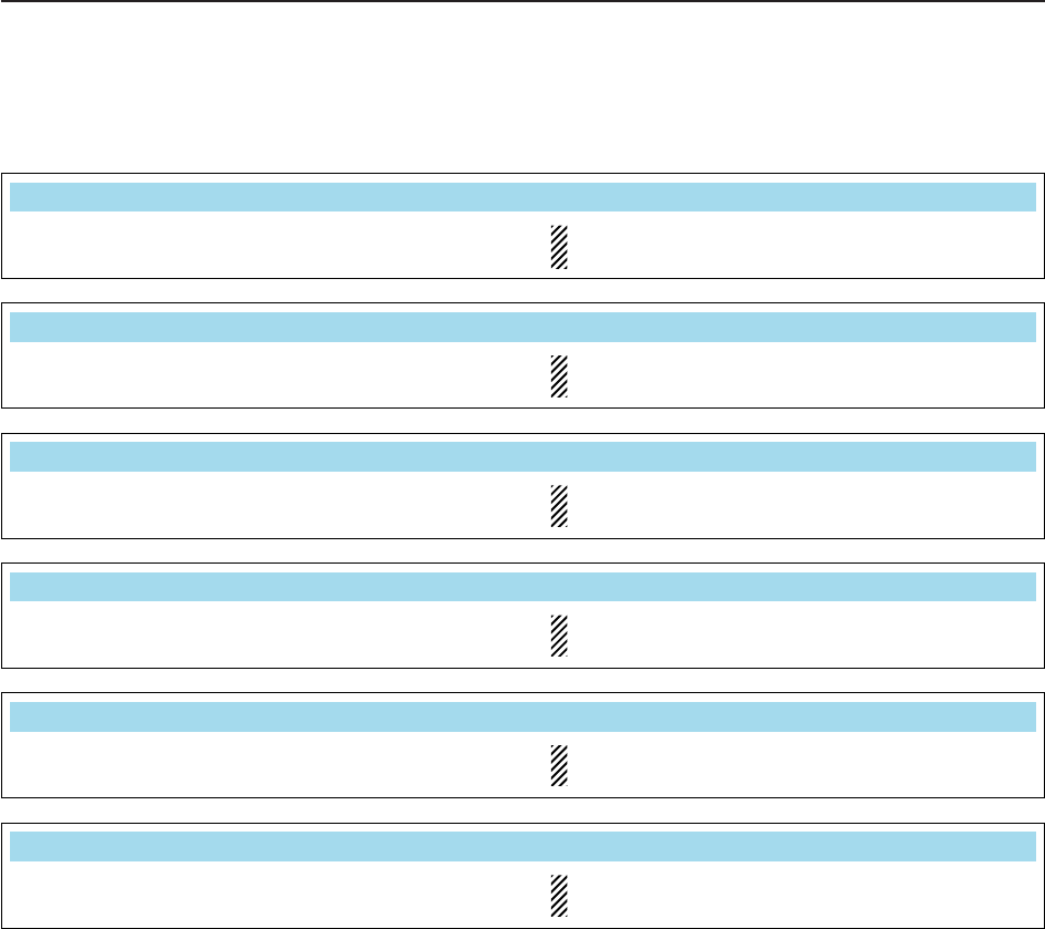
5-15
D
Filter shape set mode (continued)
5
FUNCTIONS FOR RECEIVE
Select the filter shape for CW mode in HF bands. The set filter shape is automatically used only
when the IF filter is set to 500 Hz or narrower.
CW ( – 500Hz)
SHARP
Select the filter shape for CW mode in HF bands. The set filter shape is automatically used only
when the IF filter is set to 600 Hz or wider.
CW (600Hz – )
SHARP
Select the filter shape for SSB mode in 50 MHz band. The set filter shape is automatically used only
when the IF filter is set to 600 Hz or wider.
50M SSB (600Hz – )
SOFT
Select the filter shape for SSB data mode in 50 MHz
band.
The set filter shape is automatically used only
when the IF filter is set to 600 Hz or wider.
SSB–D (600Hz – )
SHARP
Select the filter shape for CW mode in 50 MHz band. The set filter shape is automatically used only
when the IF filter is set to 500 Hz or narrower.
CW ( – 500Hz)
SHARP
Select the filter shape for CW mode in 50 MHz band. The set filter shape is automatically used only
when the IF filter is set to 600 Hz or wider.
CW (600Hz – )
SHARP
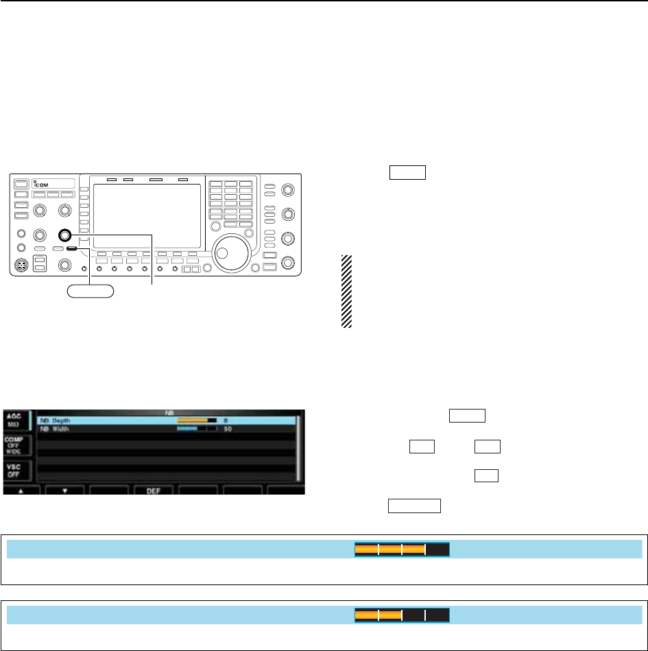
■Noise blanker
The noise blanker eliminates pulse-type noise such as
the noise from car ignitions. The noise blanker is not
available for FM mode.
qPush to turn the noise blanker function ON
and OFF.
• [NB] indicator above this switch lights green.
wRotate [NB] control to adjust the noise blanker
threshold level.
When using the noise blanker, received signals may
be distorted if they are excessively strong or the
noise type is other than impulse. Turn the noise
blanker OFF, or rotate [NB] control to a shallow po-
sition in this case.
D
NB set mode
To deal with various type of noises, attenuation level
and noise blank time can be set in NB set mode.
qPush and hold for 1 sec. to enter NB set
mode.
wPush [Y] or [Z] to select the desired item.
eRotate the main dial to set the desired level or value.
• Push and hold [DEF] for 1 sec. to select a default
value.
rPush to exit NB set mode.
EXIT/SET
F-4
F-2F-1
NB
NB
[NB] control
NB
5-16
5FUNCTIONS FOR RECEIVE
Set the noise attenuation level from 1 to 10.
NB Depth
8
Set the blank time from 1 to 100.
NB Width
50
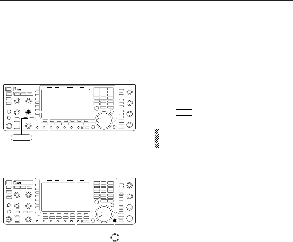
5-17
5
FUNCTIONS FOR RECEIVE
■Noise reduction
The noise reduction function reduces random noise
components and enhances desired signals which are
buried in noise. The DSP performs the random noise
reduction function.
qPush to turn the noise reduction ON.
• [NR] indicator above this switch lights green.
wRotate the [NR] control to adjust the noise reduction
level.
ePush to turn the noise reduction OFF.
• [NR] indicator lights off.
Large rotations of the [NR] control results in audio
signal masking or distortion. Set the [NR] control for
maximum readability.
■Dial lock function
The dial lock function prevents frequency changes by
accidental movement of the tuning dial. The lock func-
tion electronically locks the dial.
➥Push [LOCK] to toggle the dial lock function ON and
OFF.
• The [LOCK] indicator lights when the dial lock function
is in use.
NR
NR
[LOCK] indicator LOCK
[NR] control
NR
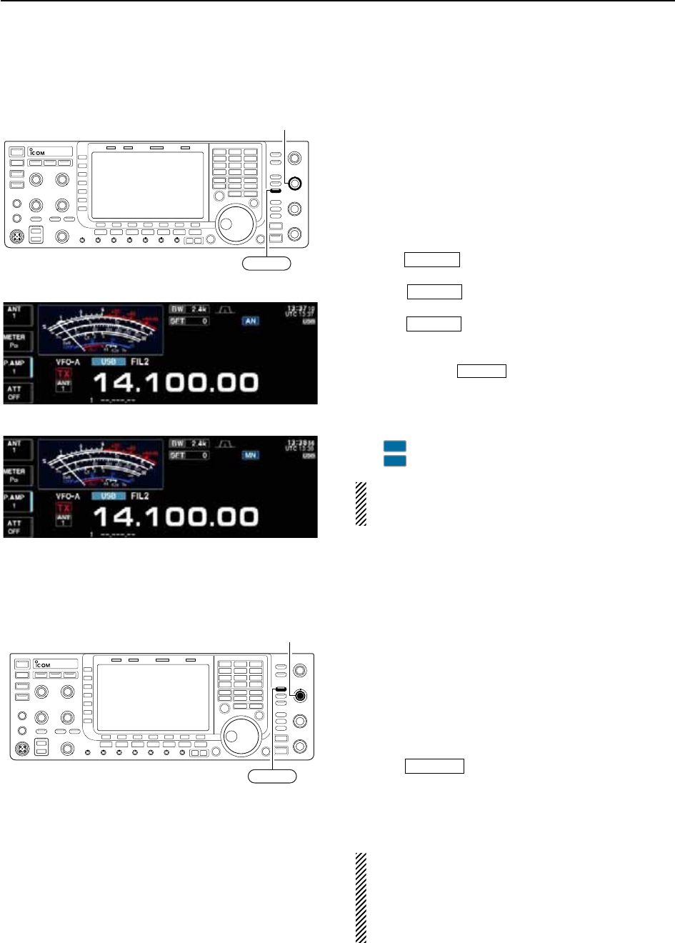
■Notch function
This transceiver has auto and manual notch functions.
The auto notch function uses DSP to automatically at-
tenuate more than 3 beat tones, tuning signals, etc.,
even if they are moving. The manual notch can be set
to attenuate a frequency via the [NOTCH] control.The
auto notch can be used in SSB, AM and FM mode.
The manual notch can be used in SSB, CW, RTTY,
PSK and AM modes.
➥Push to toggle the notch function between
auto, manual and OFF in SSB and AM modes.
➥Push to turn the manual notch function
ON and OFF in CW, RTTY, PSK modes.
➥Push to turn the auto notch function ON
and OFF in FM mode.
• [NOTCH] indicator above this switch lights green.
• Push and hold for 1 sec. to select the notch fil-
ter width for manual notch from wide, middle and nar-
row.
• Set to attenuate a frequency for manual notch via the
[NOTCH] control.
• “ ” appears when auto notch is in use.
• “ ” appears when manual notch is in use.
While tuning the manual notch, noise may be heard.
This comes from the DSP unit and does not indicate
an equipment malfunction.
■Digital selector
The digital selector manually adjusts the center fre-
quency of the automatic pre-selector.
The automatic pre-selector adds selectivity ahead of
the 1st mixer. This reduces intermodulation distortion
from the nearby strong signals.
The automatic pre-selector tracks the frequency tun-
ing, changing it’s resonant frequency in discrete steps.
qPush to turn the digital selector ON and
OFF.
• [DIGI-SEL] indicator above this switch lights green.
wRotate [DIGI-SEL] control to adjust the center fre-
quency.
NOTE:
• When rotating the main dial while the digital selec-
tor is activated, mechanical noise may be heard
due to the switching noise from internal relays.
• The preamp (P.AMP1 or P.AMP2) cannot be used
while the digital selector is activated.
DIGI-SEL
MN
AN
NOTCH
NOTCH
NOTCH
NOTCH
[NOTCH] control
NOTCH
[DIGI-SEL] control
DIGI-SEL
5-18
5FUNCTIONS FOR RECEIVE
• Manual notch indication
• Auto notch indication
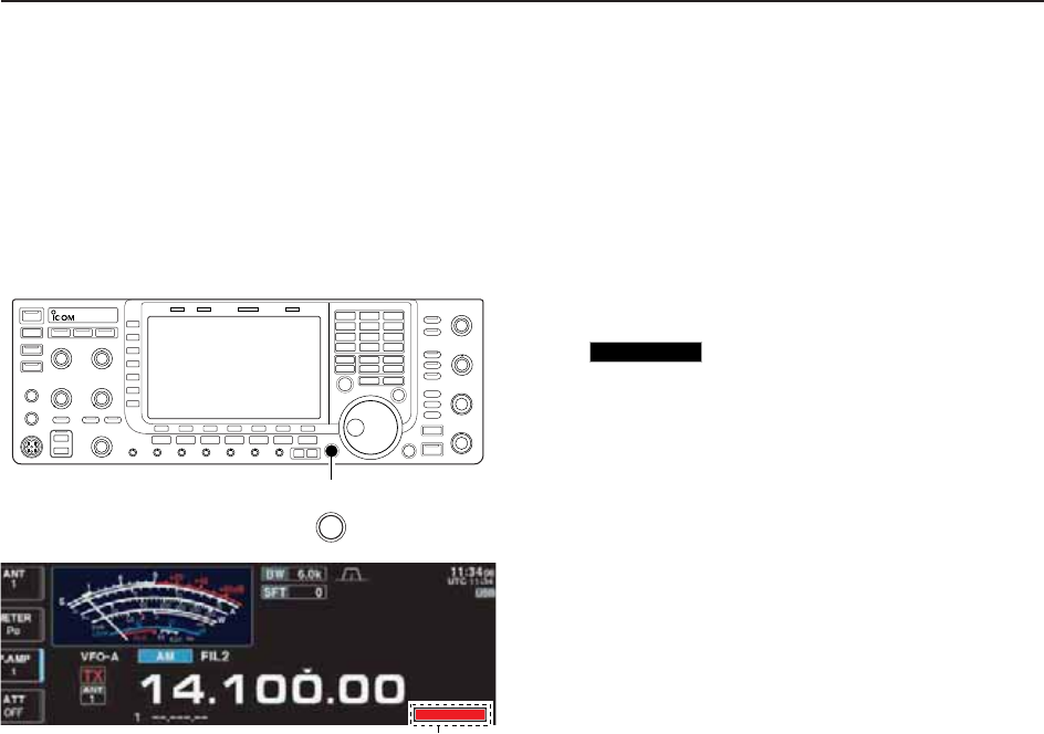
5-19
5
FUNCTIONS FOR RECEIVE
■Autotune function
The Automatic tuning function tunes the displayed fre-
quency (max. CW: 500 Hz, AM: ±5 kHz) automatically
when an off frequency signal is received. This function
is active while in CW or AM mode is selected.
➥Push [AUTOTUNE] to toggle the autotune function
ON or OFF.
•“”
blinks when autotune function is activate.
• After 30 sec. has passed, the autotune function stops
tuning automatically even it’s still off-frequency.
AUTOTUNE
Appears
AUTOTUNE
AUTO
TUNE