ICOM orporated 318300 HF/VHF/UHF Transceiver User Manual CONFIDENTIAL ShortTerm IC 9100 UserMan
ICOM Incorporated HF/VHF/UHF Transceiver CONFIDENTIAL ShortTerm IC 9100 UserMan
UserManual.wiki
>
ICOM orporated
>
318300 User Manual
>
User Manual 1
Contents
1.
User Manual 1
2.
User Manual 2
User Manual 1
Navigation menu
Upload a User Manual
Namespaces
Wiki Guide
HTML
PDF
Info
Views
User Manual
Discussion / Help
Navigation
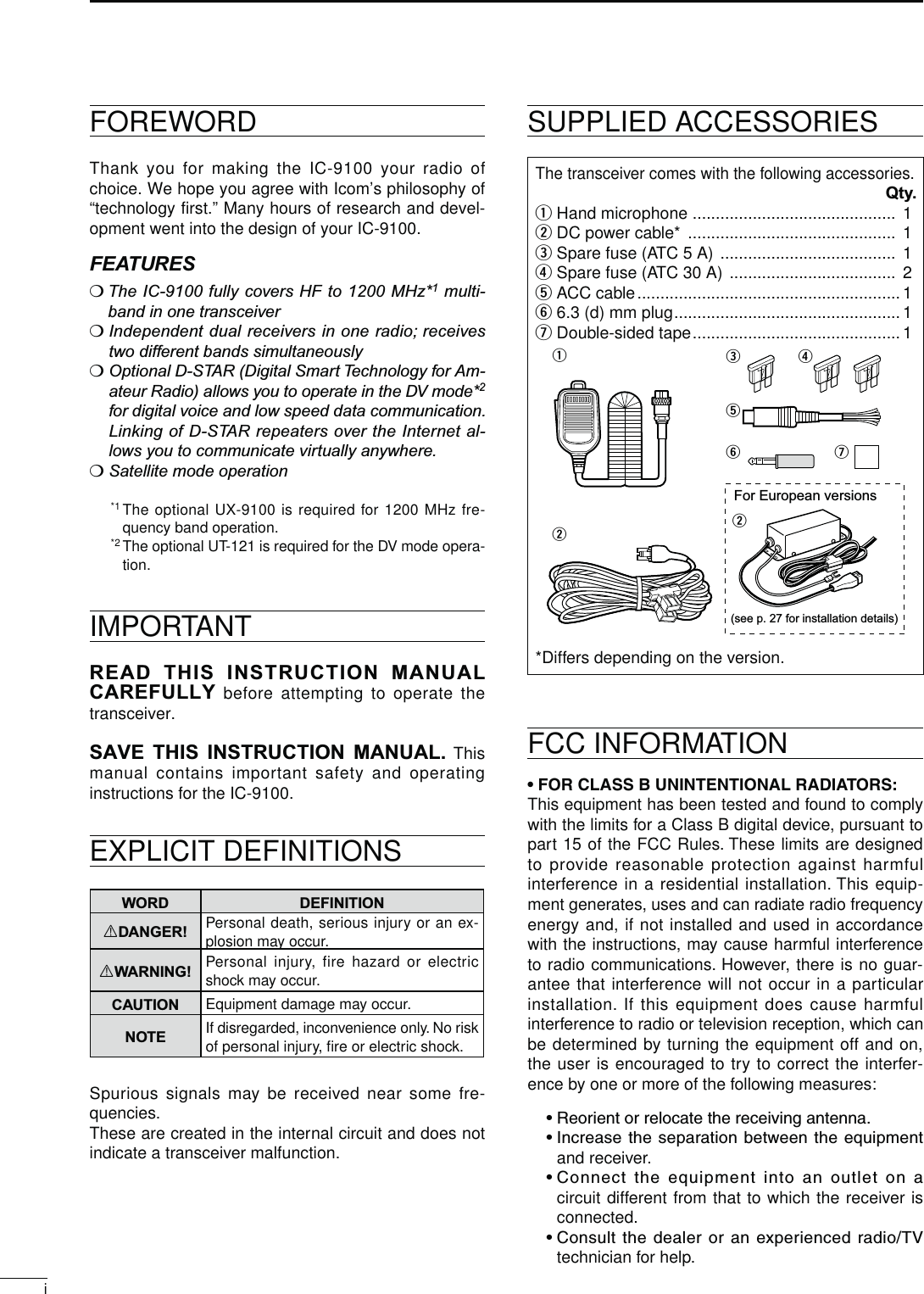
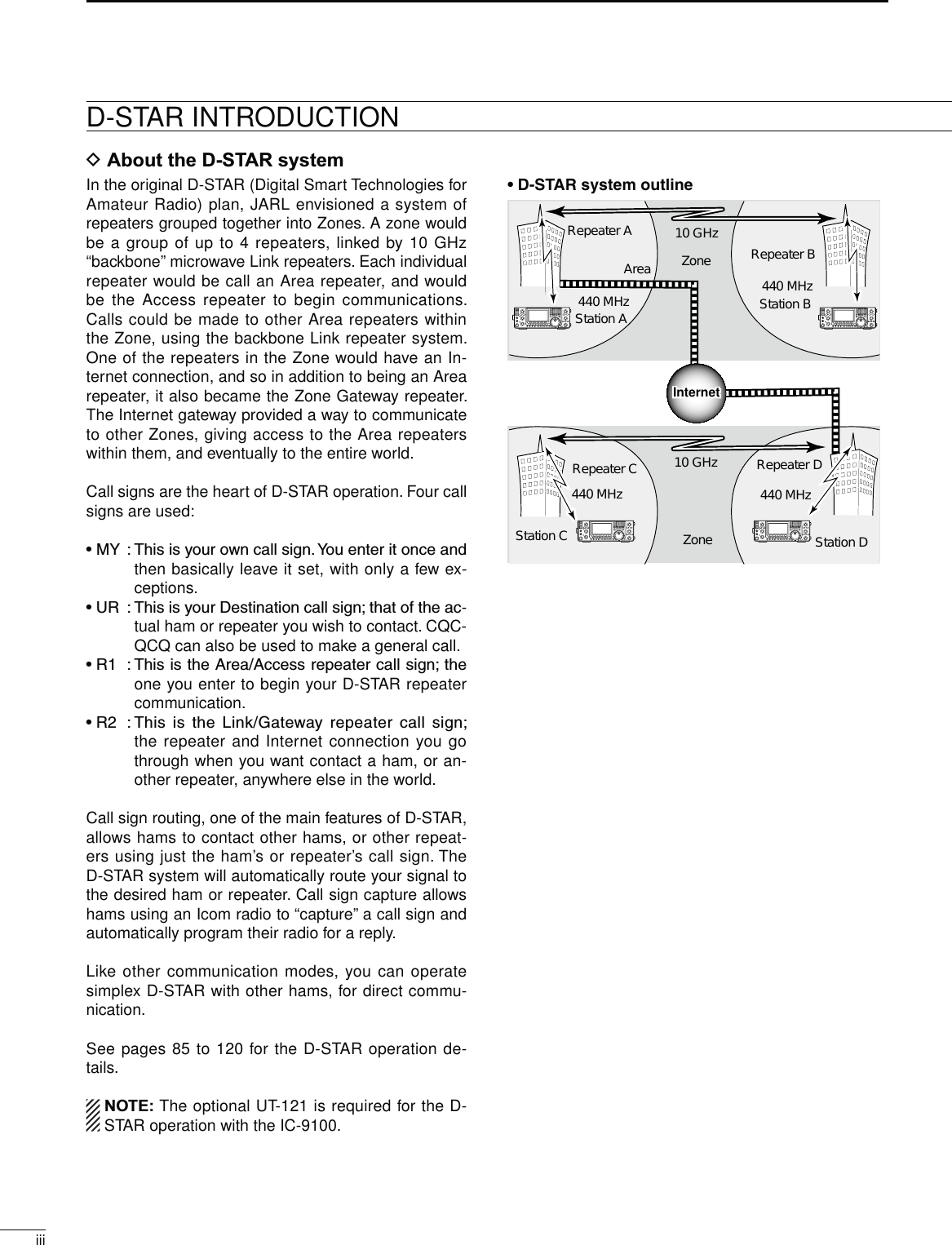
![PRECAUTIONSRDANGER HIGH RF VOLTAGE! NEVERattach an antenna or internal antenna connector during transmission. This may result in an electrical shock or burn.R WARNING! NEVER operate the transceiver with a headset or other audio accessories at high volume levels. Hearing experts advise against continu-ous high volume operation. If you experience a ringing in your ears, reduce the volume or discontinue use.R WARNING! NEVER operate or touch the transceiver with wet hands. This may result in an electric shock or damage to the transceiver.R WARNING! NEVER apply AC power to the [DC13.8V] socket on the transceiver rear panel. This could cause a fire or damage the transceiver.R WARNING! NEVER cut the DC power cable between the DC plug and fuse holder. If an incorrect connection is made after cutting, the transceiver may be damaged.R WARNING! NEVER apply more than 16 V DC to the [DC13.8V] socket on the transceiver rear panel, or use reverse polarity. This could cause a fire or damage the transceiver.R WARNING! NEVER let metal, wire or other objects protrude into the transceiver or into connectors on the rear panel. This may result in an electric shock.R WARNING! Immediately turn OFF the trans-ceiver power and remove the power cable if it emits an abnormal odor, sound or smoke. Contact your Icom dealer or distributor for advice.R WARNING! NEVER put the transceiver in any unstable place (such as on a slanted surface or vibrated place). This may cause injury and/or damage to the transceiver.CAUTION: NEVER change the internal settings of the transceiver. This may reduce transceiver perfor-mance and/or damage to the transceiver.In particular, incorrect settings for transmitter circuits, such as output power, idling current, etc., might damage the expensive final devices.The transceiver warranty does not cover any prob-lems caused by unauthorized internal adjustment.CAUTION: NEVER block any cooling vents on the top, rear, sides or bottom of the transceiver.CAUTION: NEVER expose the transceiver to rain, snow or any liquids.CAUTION:NEVERinstall the transceiver in a place without adequate ventilation. Heat dissipation may be reduced, and the transceiver may be damaged.DO NOT use harsh solvents such as benzine or alcohol when cleaning, as they will damage the trans-ceiver surfaces.DO NOT push the PTT switch when you don’t actu-ally desire to transmit.DO NOT use or place the transceiver in areas with temperatures below ±0°C (+32°F) or above +50°C (+122°F).DO NOT place the transceiver in excessively dusty environments or in direct sunlight.DO NOT place the transceiver against walls or putting anything on top of the transceiver. This may overheat the transceiver.Always place unit in a secure place to avoid inadver-tent use by children."% #!2%&5, If you use a linear amplifier, set the transceiver’s RF output power to less than the linear amplifier’s maximum input level, otherwise, the linear amplifier will be damaged."% #!2%&5, The transceiver will become hot when operating the transceiver continuously for long periods of time.USE only the specified microphone. Other manufac-turers’ microphones have different pin assignments, and connection to the IC-9100 may damage the transceiver or microphone.During maritime mobile operation, keep the trans-ceiver and microphone as far away as possible from the magnetic navigation compass to prevent errone-ous indications.Turn OFF the transceiver’s power and/or disconnect the DC power cable when you will not use the trans-ceiver for long period of time.For U.S.A. onlyCAUTION: Changes or modifications to this device, not expressly approved by Icom Inc., could void your authority to operate this device under FCC regula-tions.Icom, Icom Inc. and the Icom logo are registered trademarks of Icom Incorporated (Japan) in Japan, the United States, the United Kingdom, Germany, France, Spain, Russia and/or other countries.Microsoft, Windows and Windows Vista are registered trademarks of Microsoft Corporation in the United States and/or other countries.All other products or brands are registered trademarks or trade-marks of their respective holders.ii](https://usermanual.wiki/ICOM-orporated/318300.User-Manual-1/User-Guide-1415349-Page-3.png)
![vTABLE OF CONTENTSFOREWORD .............................................................. IIMPORTANT............................................................... IEXPLICIT DEFINITIONS............................................ ISUPPLIED ACCESSORIES....................................... IFCC INFORMATION .................................................. IPRECAUTIONS......................................................... IID-STAR INTRODUCTION........................................ III D About the D-STAR system ................................iii D D-STAR system description ..............................iv4!",%/&#/.4%.43 ............................................ v1 PANEL DESCRIPTION................................... 1–21N Front panel ........................................................ 1N Rear panel....................................................... 10 D ACC socket information .............................. 13 D DATA2 socket information ........................... 14N LCD display..................................................... 15N Function display .............................................. 19 D M1 (Menu 1) display.................................... 19 D M2 (Menu 2) display.................................... 19 D M3 (Menu 3) display.................................... 19 D D1 display ................................................... 19 D D2 display ................................................... 19 D Function keys on M1 (Menu 1) display ....... 20 D Function keys on M2 (Menu 2) display ....... 20 D Function keys on M3 (Menu 3) display ....... 21 D Function keys on D1 display ....................... 21 D Function keys on D2 display ....................... 212 INSTALLATION AND CONNECTIONS........ 22–30N Selecting a location......................................... 22N Grounding ....................................................... 22N Electronic keyer and microphone connections 22N Antenna connection ........................................ 23N Required connections ..................................... 24 DRear panel .................................................. 24N Advanced connections.................................... 25 DFront panel.................................................. 25 DRear panel .................................................. 25N External keypad connections .......................... 26N Optional and the external units connections ... 26N Power supply connections............................... 27N Connecting a DC power supply....................... 27 D Connecting the PS-126$#0/7%23500,9 ................................. 27 D Connecting a non-Icom$#0/7%23500,9 ................................. 27N Linear amplifier connections ........................... 28 DConnecting the IC-PW1/PW1EURO........... 28 DConnecting a non-Icom linear amplifier ...... 29N External antenna tuner connection ................. 29 DConnecting the AH-4 .................................. 29N Microphone connector information.................. 30N Microphones.................................................... 30 DHM-36......................................................... 30 D SM-50 (Option) ........................................... 303"!3)#/0%2!4)/...................................... 31–46N Before first applying power.............................. 31N Turning ON (Partial resetting).......................... 31N MAIN and SUB Bands..................................... 32 DMAIN/SUB Band selection.......................... 32 DSUB Band display....................................... 32 DSUB Band setting mode operation ............. 33 DThe SUB Dial function................................. 33N VFO description............................................... 34 D Selecting the VFO A/B ............................... 34 D VFO equalization........................................ 34N Selecting VFO/memory mode ......................... 34N Selecting a frequency band............................. 35 DUsing the band stacking registers............... 35N Frequency setting............................................ 37 DTuning with [MAIN DIAL]............................. 37 DDirect frequency entry with the keypad....... 37 DQuick tuning function .................................. 38 DSelecting “kHz” step.................................... 38 DSelecting 1 Hz step..................................... 39 DAuto tuning step function ............................ 39 D1⁄4 tuning step function............................... 39 D About the 5 MHz frequency band operation (only USA version)...................................... 40 DBand edge warning beep............................ 41 DProgramming the user band edge .............. 42N Operating mode selection ............................... 43N Squelch and receive (RF) sensitivity............... 44N Volume setting................................................. 45N Voice synthesizer operation............................. 45N Meter Display selection ................................... 45N Basic transmit operation.................................. 46 DTransmitting................................................. 46 DMicrophone gain adjustment....................... 464 RECEIVE AND TRANSMIT .......................... 47–68N Operating SSB ................................................ 47N Operating CW ................................................. 48 D About the CW reverse mode....................... 49 D About CW pitch control ............................... 49 D About keying speed..................................... 49 D CW sidetone function.................................. 49](https://usermanual.wiki/ICOM-orporated/318300.User-Manual-1/User-Guide-1415349-Page-6.png)
![viii12345678910111213141516171819202112 SATELLITE OPERATION......................... 153–157N Satellite communications outline................... 153N Satellite notes................................................ 153N Selecting the satellite mode .......................... 153 DTransferring the VFO frequencies to the satellite VFO.............................................. 153N Setting the satellite VFO................................ 154N Tracking selection.......................................... 154 D Normal tracking......................................... 154 D Reverse tracking ....................................... 154N Satellite memory ........................................... 155 D Satellite memory selection........................ 155 D Satellite memory programming................. 155N Preparation.................................................... 156N Satellite operation ......................................... 15713 ANTENNA TUNER OPERATION ............. 158–160N Antenna connection and selection ................ 158N Antenna tuner operation................................ 159 D Tuner operation ......................................... 159 D Manual tuning ........................................... 159N Optional external tuner operation.................. 16014 SET MODE ............................................... 161–172N Set mode description .................................... 161 D The Set mode settings .............................. 161N Tone control Set mode description................ 169 D The Tone control Set mode settings.......... 16915 DATA COMMUNICATION......................... 171–173N Connections .................................................. 171 D When connecting to [DATA2]..................... 171 D When connecting to [ACC]........................ 171 D When connecting to [MIC]......................... 171N Packet (AFSK) operation............................... 172 D Frequency display during AFSK operation 172N Data transmission speed............................... 173N Adjusting the TNC output level...................... 173 D Using a level meter or synchroscope........ 173 D Not using a measuring device................... 17316 OPTION INSTALLATION ......................... 174–176N Opening the transceiver’s case ..................... 174N UX-9100 1200 MHz BAND UNIT installation ...... 175N FL-430/FL-431 1ST IF FILTER installation........ 176N UT-121 DIGITAL UNIT installation ..................... 17617 MAINTENANCE ....................................... 177–182N Troubleshooting ............................................. 177 DTransceiver power..................................... 177 DTransmit and receive................................. 177 DScanning................................................... 178 DDisplay...................................................... 178N Frequency calibration (approximate)............. 179N Main dial tuning tension adjustment.............. 179N Fuse replacement ......................................... 180 DDC power cable fuse replacement............ 180 DCircuitry fuse replacement........................ 180N Resetting the CPU ........................................ 181 DPartial reset............................................... 181 DAll reset..................................................... 181N Data cloning .................................................. 182 DCloning between transceivers.................... 182 DCloning using a personal computer ........... 18218 CONTROL COMMAND ............................ 183–196N Remote jack (CI-V) information..................... 183 DCI-V connection example.......................... 183 DData format............................................... 183 DCommand table ........................................ 184 DData content description........................... 19019 SPECIFICATIONS .................................... 197–198N General.............................................................. 197N Transmitter..................................................... 197N Receiver........................................................ 198N Antenna tuner................................................ 19820 OPTIONS.................................................. 199–20021 CE............................................................. 201–202](https://usermanual.wiki/ICOM-orporated/318300.User-Manual-1/User-Guide-1415349-Page-9.png)
![11PANEL DESCRIPTIONqPOWER SWITCH [POWER] (p. 31)±Push to turn ON the transceiver power. s&IRSTCONlRMTHE$#POWERSOURCEISTURNED/.±Hold down for 1 second to turn OFF the power.wTRANSMIT SWITCH [TRANSMIT] (p. 46)Push to select transmit or receive.s7HILETRANSMITTINGTHE-!).OR35""ANDS4828IN-dicator (i or !5) lights red.s7HILERECEIVINGORWHENTHESQUELCHOPENSTHEINDICA-tor lights green.eANTENNA TUNER SWITCH [TUNER] (p. 159) &REQUENCYBAND(&-(Z± Push to turn the internal antenna tuner ON or OFF (bypass).sh ” appears when the tuner is turned ON.s4HEINTERNALANTENNATUNERSETTINGSCANBEMEMO-rized in each frequency band.±Hold down for 1 second to manually start the an-tenna tuner.s)FTHETUNERCANNOTTUNETHEANTENNAWITHINSEC-onds, the tuning circuit is automatically bypassed.r !.4%..!s-%4%237)4#(;!.4s-%4%2= !.4%..!37)4#(/PERATION(p. 158) &REQUENCYBAND(&-(Z± Push to select either the ANT1 or ANT2 connec-tor. -%4%237)4#(/PERATION(p. 45) &REQUENCYBAND!,,± Hold down for 1 second to toggle the transmit meter function between ALC, COMP and SWR.tHEADPHONE JACK [PHONES] Plug in standard stereo headphones (impedance: 8 to 16 ø). s/UTPUTPOWER-ORETHANM7WITHANø load.s7HENHEADPHONESARECONNECTEDTHEINTERNALSPEAKERand any external speaker, are disabled.s4HE-!).AND35""ANDAUDIOCANBEMIXEDORSEPA-rated when using stereo headphones, depending on the “Phone Separate” option in the Set mode. (p. 160)yELECTRONIC KEYER JACK [ELEC-KEY] Plug in a bug or paddle type key to use the internal electronic keyer for CW operation. (p. 22)s3ETTHEKEYERTYPETO%,%#+%9"5'+%9OR3TRAIGHTkey in the “Keyer Type” item of the Keyer Set mode.s!STRAIGHTKEYJACKISLOCATEDONTHEREARPANEL3EE;+%9=ONPAGEs9OU CAN REVERSE THE KEYER PADDLE POLARITY DOT ANDdash) in the “Paddle Polarity” item ofthe Keyer Set mode.(p. 55)s&OURKEYERMEMORYCHANNELSAREAVAILABLEFORYOURCON-venience. (p. 51)otoauMICROPHONE CONNECTOR [MIC]Plug in the supplied or an optional microphone. s3EEPAGEFORAPPROPRIATEMICROPHONES s3EEPAGEFORMICROPHONECONNECTORINFORMATIONi-!)."!.$4828).$)#!4/2± Lights green when the squelch opens, or a signal ISRECEIVEDONTHE-!)."ANDLIGHTSREDDURINGtransmit.± Blinks green when an off-frequency signal is re-ceived, depending on the “FM/DV Center Error” option in the Set mode. (p. 162)N&RONTPANELti !0yqeruo!2!1w](https://usermanual.wiki/ICOM-orporated/318300.User-Manual-1/User-Guide-1415349-Page-10.png)
![21PANEL DESCRIPTION1o-!)."!.$2&'!).#/.42/,SQUELCH CONTROL [RF/SQL] OUTERCONTROLP Rotate to adjust the RF gain and squelch threshold level for the MAIN Band. The squelch removes noise output to the speaker when no signal is received. (closed condition)s4HESQUELCHISPARTICULARLYEFFECTIVEFOR!-AND&-BUTalso works in other modes.s4HETOOCLOCKPOSITIONISRECOMMENDEDfor the most effective use of the [RF/SQL] control. s[RF/SQL] operates as only an RF gain control in SSB, #7AND2449Squelch is fixed open), or a squelch control in AM, FM and DV (RF gain is fixed at maxi-mum sensitivity), when “Auto” is selected as the “RF/SQL Control” item option in the Set mode. (p. 162)s7HENUSEDASAN2&GAINSQUELCHCONTROLMaximumRF gainS-metersquelchNoise squelch (FM/DV modes)Squelch is open.RF gain adjustablerangeRecommended levels7HENUSEDASAN2&GAINCONTROL3QUELCHISlXEDOPEN33"#7AND2449ONLYMinimum RF gainAdjustablerangeMaximumRF gainWhile rotating the RF gain control, a faint noise may be heard. This comes from the DSP unit and does not indicate an equipment malfunction.s7HENUSEDASASQUELCHCONTROL(RF gain is fixed at maximum.)Squelch is open.S-metersquelchS-meter squelchthresholdNoise squelch threshold(FM mode)Shallow DeepNoise squelch (FM/DV modes)!0-!)."!.$!&#/.42/,;!&=INNERCONTROLP Rotate to adjust audio output level to the speaker or headphones on the MAIN Band.n reaeDe rea e!1 NOTCH SWITCH [NOTCH] (p. 77) -ODE!UTONOTCH 33"!-&- -ANUALNOTCH33"#72449!-±In the SSB and AM modes, push to toggle the notch function between auto, manual and OFF. s%ITHERTHE!UTOOR-ANUALNOTCHFUNCTIONCANBEturned OFF in the “[NOTCH] SW” item of the Set mode. (p. 36)±In the FM mode, push to turn the Auto Notch function ON or OFF.±In the #7OR2449 mode, push to turn the Man-ual Notch function ON or OFF.sh-.&vAPPEARSWHENTHE-ANUAL.OTCHFUNCTIONISON. sh!.&vAPPEARSWHENTHE!UTO.OTCHFUNCTIONIS/.s.OINDICATORAPPEARSWHENTHENOTCHlLTERIS/&&± Hold down for 1 second to switch the manual filter characteristics from wide, mid and narrow, when the Manual Notch function is selected. What is the notch filter?The notch filter is a narrow filter that eliminates un-wanted CW or AM carrier tones, while preserving the desired voice signal. The DSP circuit automati-cally adjusts the notch frequency to effectively elim-inate unwanted tones.!2 MANUAL NOTCH FILTER CONTROL [NOTCH]OUTERCONTROLP Rotate to adjust the notch frequency to reject an interfering signal while the manual function is ON. s.OTCHlLTERCENTERFREQUENCY 33"2449 n(ZTO(ZCW : CW pitch freq. –2540 Hz to CW pitch freq. +2540 HzAM : –5060 Hz to +5100 HzHigher frequencyLower frequencyThe optional UX-9100 is required for 1200 MHz frequency band operation.The optional UT-121 is required for DV mode operation.](https://usermanual.wiki/ICOM-orporated/318300.User-Manual-1/User-Guide-1415349-Page-11.png)
![!3 MENU SWITCH [MENU] (p. 19)± Push to change the set of functions assigned to switches ([F-1] to [F-5]).s4OGGLES THE FUNCTION DISPLAY MENU BETWEEN -(Menu 1), M2 (Menu 2), M3 (Menu 3), D1 and D2.± Hold down for 1 second to enter the Set mode. Push to return to the previous screen display.!4 NOISE REDUCTION LEVEL CONTROL [NR]INNERCONTROLP Rotate to adjust the DSP noise reduction level when the noise reduction function is in use. Set for maximum readability. s4OUSETHISCONTROLlRSTPUSH[NR] (!5).IncreasesDecreases!5 NOISE REDUCTION SWITCH [NR] (p. 77)Push to turn DSP noise reduction ON or OFF. sh.2vAPPEARSWHENNOISEREDUCTIONIS/.!635""!.$4828).$)#!4/2 Lights green when the squelch opens, or a signal is RECEIVEDONTHE35""ANDLIGHTSREDDURINGTRANS-mit in the satellite mode.± Blinks green when an off-frequency signal is re-ceived, depending on the “FM/DV Center Error” option in the Set mode. (p. 162)!735""!.$2&'!).#/.42/,SQUELCH CONTROL [RF/SQL] OUTERCONTROLP Rotate to adjust the RF gain and squelch threshold level on the SUB Band. The squelch stops noise output to the speaker when no signal is received. (closed condition)See o on page 2 for details.!8 35""!.$!&#/.42/,;!&=INNERCONTROLP Rotate to adjust audio output level to the speaker or headphones on the SUB Band.!9 MIC GAIN CONTROL [MIC GAIN] (p. 46)Rotate to adjust the microphone gain.s4HETRANSMITAUDIOTONEINTHE33"!-AND&-MODESCANbe independently adjusted in the tone control Set mode. (p. 169) How to set the microphone gain.Set the meter function to ALC. (p. 45) While speak-ing at normal voice level, adjust the [MIC GAIN] control so that in the SSB or AM modes, the ALC meter swings within the ALC range.Recommended level for Icom microphonesIncreasesDecreases@0 RF POWER CONTROL [RF POWER] (p. 46) Rotate to continuously vary the RF output power.IncreasesDecreases&REQUENCYBAND 2&OUTPUTPOWERRANGEHF/50 MHz 2 to 100 W (AM: 2 to 30 W)144 MHz 2 to 100 W430 MHz 2 to 75 W1200 MHz 1 to 10 W@1 CW PITCH CONTROL [CW PITCH]OUTERCONTROLP -ODE#7 Rotate to shift the received CW audio pitch and the CW sidetone pitch without changing the operating frequency.s4HEPITCHCANBEADJUSTEDFROMTO(ZINAP-proximatly 5 Hz steps.Higher pitchLower pitchN Front panel (continued)31PANEL DESCRIPTION!6 !8!7!4!5!9 @0 @1 @2 @3 @4 @5 @6 @7 @8!38](https://usermanual.wiki/ICOM-orporated/318300.User-Manual-1/User-Guide-1415349-Page-12.png)
![@2 ELECTRONIC CW KEYER SPEED CONTROL [KEY SPEED] (p. 49) -ODE#7 Rotate to adjust the keying speed of the internal electronic CW keyer to between 6 wpm (minimum) and 48 wpm (maximum).FastSlow@302%!-0s!44%.5!4/237)4#(;0!-0s!44=PREAMP SWITCH/PERATION(p. 71) &REQUENCYBAND(&-(Z± Push to select one of two receive RF preampli-fiers, or to bypass them.sh0!-0 ” is a wide dynamic range preamplifier. It is most effective for the 1.8 to 21 MHz bands.sh0!-0 ” is a high-gain preamplifier. It is most ef-fective for the 24 to 50 MHz bands.s.OINDICATORAPPEARSWHENTHEPREAMPLIlERSARENOTselected. &REQUENCYBAND-(Z± Push to turn an optional AG-25, AG-35 or AG-1200* pre-amplifier unit ON or OFF, if installed.sh0!-0vAPPEARSWHENTHEPREAMPLIlERUNITIS/. *AG-1200 has been discontinued, but it can be still be used. What is the preamplifier?The preamplifier amplifies signals in the front end to improve the S/N ratio and sensitivity. Select “P. AMP” or “P. AMP ” when receiving weak signals. !44%.5!4/237)4#(/PERATION(p. 71)± Hold down for 1 second to turn ON the attenua-tor.sh!44vAPPEARSWHENTHEATTENUATORIS/.± Push to turn OFF the attenuator. sh!44vDISAPPEARS What is the attenuator?The attenuator prevents a desired signal from being distorted when very strong signals are near it, or when very strong electromagnetic fields, such as from a broadcasting station, are near your location.@4./)3%",!.+%237)4#(;."= (p. 76)± Push to turn the noise blanker ON or OFF. The noise blanker reduces pulse-type noise such as that generated by vehicle ignition systems. The noise blanker is not effective for non-pulse-type noise.sh."vAPPEARSWHENTHENOISEBLANKERIS/.± Hold down for 1 second to display the “NB” screen. Push to return to the previous screen display.@56/8"+).37)4#(;6/8"+).=VOX SWITCH/PERATION(p. 78) -ODE33"!-&-$6± Push to turn the VOX function ON or OFF.± Hold down for 1 second to display the “VOX” screen. Push to return to the previous screen display. What is the VOX function?The VOX function (voice operated transmission) automatically starts transmission when you speak INTOTHEMICROPHONETHENAUTOMATICALLYRETURNSTOreceive when you stop speaking."+).37)4#(/PERATION(p. 79) -ODE#7± Push to toggle the break-in operation between semi break-in and full break-in, or to turn OFF the break-in function.± Hold down for 1 second to display the “BKIN” screen (Break-in). Push to return to the previous screen display. What is the break-in function?The break-in function automatically switches be-tween transmit and receive with your CW keying. Using Full break-in function (QSK), you can hear the receive frequency in-between keying.@6 MONITOR SWITCH [MONITOR] (p. 81)± Push to turn the Monitor function ON or OFF to listen to your own transmitted audio. sh-/.)vAPPEARSWHENTHISFUNCTIONIS/.s)N#7MODETHE#7SIDETONECANBEHEARDREGARD-less of the [MONITOR] switch setting.± Hold down for 1 second to display the “MONI” screen (Monitor) to set the monitor level. Push to return to the previous screen display.@7#!,,s'0337)4#(;#!,,s'03=CALL SWITCH/PERATION(p. 139) Push to select the call channel.GPS SWITCH/PERATION(p. 121)Hold down for 1 second to display the “GPS” screen. Push to return to the previous screen display.@8 FUNCTION SWITCHES [F1]–[F5] Push to select the function which is indicated on the LCD display above each switch. (p. 19)s4HEFUNCTIONSVARYDEPENDINGONTHESELECTEDMENUand the operating mode.41PANEL DESCRIPTION1The optional UX-9100 is required for 1200 MHz frequency band operation.](https://usermanual.wiki/ICOM-orporated/318300.User-Manual-1/User-Guide-1415349-Page-13.png)
![@9 MODE SWITCHESPush to select your desired operating mode. (p. 43)s4HEBUILTINSPEECHSYNTHESIZERANNOUNCESTHESELECTEDmode when the “SPEECH [MODE] SW” item is set to “ON” in the Set mode. (p. 164) ;33"= (p. 47)±Push to alternately select the USB or LSB modes. sh53"vORh,3"vAPPEARS±In the SSB mode, hold down for 1 second to se-lect the SSB data mode (USB-D, LSB-D).shD” appears in addition to “USB” or “LSB.”±In the SSB data mode, push to return to the normal SSB mode.[CW/RTTY] (pp. 48, 56)±0USH TO ALTERNATELY SELECT THE #7 OR 2449modes. sh#7vORh2449vAPPEARS± Hold down for 1 second to switch between the CW and CW-R (CW reverse) modes, in the CW mode.sh#72vAPPEARSWHENTHE#7REVERSEMODEISselected.± Hold down for 1 second to switch between the 2449AND244922449REVERSEMODESINTHE2449MODEsh24492vAPPEARSWHENTHE2449REVERSEMODEISselected.[AM/FM] (p. 61)±Push to alternately select the AM or FM modes. sh!-vORh&-vAPPEARS± Hold down for 1 second to select the AM or FM data mode (AM-D/FM-D).shD” appears in addition to “AM” or “FM.”± In the data mode, push to return to the normal AM or FM mode.NOTE:s)NTHE!-MODEYOUCANTRANSMITONONLYTHEHF/50MHz frequency bands.s4HE!-MODECANNOTBESELECTEDONTHEMHz frequency band. ;$6s$2= (p. 85)±Push to select the DV mode. sh$6vBLINKS±Hold down for 1 second to select the DR mode.sh$6vh” and “r” appear.±In the DR mode, push to cancel it.sh” and “r” disappear.#0 FILTER SWITCH [FILTER] (p. 73)± Push to select one of three IF filter settings ( / /).s4HESELECTEDlLTERPASSBANDWIDTHANDSHIFTINGVALUEare displayed for 2 seconds on the LCD display.± Hold down for 1 second to display the “FIL” screen (Filter) to set the filter passband width.±When the “FIL” screen is displayed, hold down for 1 second to return to the previous screen display.#1TRANSMIT FREQUENCY CHECK SWITCH [XFC]± During split frequency or repeater operation, hold down to listen to the transmit frequency. (p. 82)s7HILE HOLDINGDOWNTHIS SWITCHTHE TRANSMITFRE-quency can be changed with the main dial, keypad or memo pad.s7HEN THE SPLIT LOCK FUNCTION IS TURNED /. PUSH[XFC] to cancel the dial lock function. (pp. 82, 162)± When the RIT function is turned ON, hold down to listen to the receive frequency. (RIT is temporarily cancelled.) (p. 69)± When the ∂TX function is turned ON, hold down to listen to the transmit frequency (including ∂TX frequency offset). (p. 81)± In the simplex operation, hold down to listen to the receive frequency.s4HESQUELCHISCLOSEDANDTHEINTERFERENCEREJECTfunction is temporary OFF while holding down this switch.± In the DV mode, the RX monitoring mode is se-lected by holding down this switch. (p. 118)N Front panel (continued)51PANEL DESCRIPTION@9 #0#2#3#4#5 #6 #7#1](https://usermanual.wiki/ICOM-orporated/318300.User-Manual-1/User-Guide-1415349-Page-14.png)
![#26&/3%,%#437)4#(;!"= (pp. 32, 34)±Push to select either VFO A or VFO B. ±Hold down for 1 second to equalize the undis-played VFO settings to that of the displayed VFO.#3 SPLIT SWITCH [SPLIT] (p. 82)± Push to turn the split function ON or OFF. sh30,)4vAPPEARSWHENTHESPLITFUNCTIONIS/.s4HE SPLIT FUNCTION IS NOT SELECTABLE ON THE 35"Band.± Hold down for 1 second to activate the quick split function.s4HETRANSMITFREQUENCYSHIFTSFROMTHERECEIVEFRE-quency according to the “SPLIT Offset” option in the Set mode. (p. 162)s4HEQUICKSPLITFUNCTIONCANBETURNED/&&INthe “Quick SPLIT” item of the Set mode. (p. 162)#435"37)4#(;35"=± Push to turn the SUB Band setting mode ON or OFF. (p. 33)sh” appears when the SUB Band setting mode is ON.± Hold down for 1 second to turn the SUB Band display ON or OFF. (p. 32)#5-!).35"s"!.$37)4#(;-!).35"s"!.$=± Push to toggle between the MAIN Band and the SUB Band. (p. 32)± Hold down for 1 second several times to select HF/50 MHz, 144 MHz, 430 MHz or 1200 MHz frequency band as your operating band. (p. 35)s4HEFREQUENCYBANDSELECTEDINEITHERTHE-!).ORSUB Band, cannot be selected on the other Band.#6 SATELLITE SWITCH [SATELLITE] (p. 153)± Push to enter the satellite mode (receive on MAIN Band, transmit on SUB Band).sh ” appears.s4HELASTOPERATEDFREQUENCIESDOWNLINKANDUPLINKand tracking icon (“ ”/“ ”) appears.± In the satellite mode, push to return to the previ-ous screen display.NOTE: In the DR mode, pushing [SATELLITE] cancels DR, and then switches the transceiver to the satellite mode.If you want to operate in the DR mode after exiting the satellite mode, you must hold down ;$6s$2=FORSECOND± Hold down for 1 second to transfer the uplink and downlink frequencies into the satellite VFO.s4HESATELLITEMODEISAUTOMATICALLYSELECTEDAFTERtransferring.sh ” appears.s4HELASTOPERATEDTRACKINGICONh ”/“ ”)appears.s4OTOGGLETHETRACKINGOPERATIONBETWEENNORMALANDreverse, push [NOR/REV] (7 3).± In the satellite mode, hold down for 1 second to return to normal operation using the displayed frequencies.#7"!.$+%93+%90!$"!.$+%93/PERATION (pp. 35, 36) When the HF/50 MHz frequency band is not se-lected in both the MAIN or SUB Band, you can se-lect the HF/50 MHz frequency band by just holding down the band key for 1 second. &REQUENCYBAND(&-(Z± Push to select the operating band. s;'%.%s=SELECTSTHEGENERALCOVERAGEBAND± Pushing the same key two or three times calls up other stacked frequencies in the frequency band. s)COMSTRIPLEBANDSTACKINGREGISTERMEMORIZESTHREEfrequencies in each frequency band. &REQUENCYBAND-(Z±0USHING;'%.%s=TWOORTHREETIMESCALLSUPother stacked frequencies in the frequency band, after selecting the 144 MHz, 430 MHz or 1200 MHz frequency band by holding down [BAND](MAIN/SUB) for 1 second.± Hold down for 1 second to switch the operating band to the HF/50 MHz frequency band. s;'%.%s=SELECTSTHEGENERALCOVERAGEBANDsPushing the same key two or three times calls up other stacked frequencies in the frequency band. +%90!$/PERATION (p. 37) After pushing [F-INP ENT], push the keys on the keypad to enter a frequency. After entering, push [F-INP ENT] to set the frequency. s%XAMPLE4OENTER-(Z 0USH;&).0%.4=;=;=;s=;=;=;=;&).0%.4=NOTE: The frequency band, selected in either the MAIN or SUB Band, cannot be selected on the other Band. While in the satellite mode, the keypad operation is different than described above. See page 154 for details.61PANEL DESCRIPTION1The optional UX-9100 is required for 1200 MHz frequency band operation.The optional UT-121 is required for DV mode operation.](https://usermanual.wiki/ICOM-orporated/318300.User-Manual-1/User-Guide-1415349-Page-15.png)
![#8 VFO/MEMORY SWITCH [VFO/MEMO]± Push to switch between the VFO and memory modes. (pp. 34, 139)± Hold down for 1 second to copy the memory con-tents to the displayed VFO on the MAIN Band. (p. 142)#9 MEMO PAD-WRITE SWITCH [MP-W] (p. 144) Push to write the displayed data into a memo pad.s4HEMOSTRECENTENTRIESREMAININTHEMEMOPADSs4HEMEMOPADCAPACITYCAN BEEXTENDEDFROM TO10 in the “Memopad Numbers” item of the Set mode. (p. 164)$0 MEMORY WRITE SWITCH [MW] (p. 140) Hold down for 1 second to store VFO data into the selected memory channel. s4HISCANBEDONEINBOTHTHE6&/ANDMEMORYMODES$1 MEMO PAD-READ SWITCH [MP-R] (p. 144)Push to sequentially call up the contents from the memo pads. The 5 (or 10) most recently programmed frequen-cies and operating modes can be recalled, starting from the most recent.s4HEMEMOPADCAPACITYCANBEINCREASEDFROMTO10 in the “Memopad Numbers” item of the Set mode. (p. 164)$2 MEMORY CLEAR SWITCH [M-CLR] (p. 141)In the Memory mode, hold down for 1 second to clear the memory channel. s4HECHANNELBECOMESABLANKCHANNELsThis switch is disabled in the VFO mode.$345.).'34%0s2%0%!4%2'2/5037)4#(;43s'20= 45.).'34%037)4#(/PERATION (p. 38)±Push to toggle between the kHz and MHz* quick tuning step, or turn OFF the quick tuning. * When the HF/50 MHz frequency band is selected, MHz step cannot be selected.s7HENTHEhZ” quick tuning icon is displayed above the kHz or MHz digit, the frequency is changed in programmed quick tuning steps or 1 MHz steps.s7HEN THE QUICK TUNING IS /&& THE FREQUENCY ISchanged in 10 Hz steps.± When the quick tuning is ON, hold down for 1 second to display the “TS” screen (Tuning Step) to select the quick tuning step. (p. 38)sANDK(Zsteps are independently selectable for each operat-ing mode.± When the quick tuning is OFF, hold down for 1 second to turn the minimum tuning step of 1 Hz ON or OFF. (p. 39) #!,,3)'.'2/5037)4#(/PERATION (p. 93)±Push to switch the call sign group.±Hold down for 1 second to enter the repeater call sign group selection mode.sh≈” blinks.± When in the repeater group selection mode, push to cancel it.N Front panel (continued)71PANEL DESCRIPTION$6$4$3#8 #9$0 $1 $2$7$8$9%0$5](https://usermanual.wiki/ICOM-orporated/318300.User-Manual-1/User-Guide-1415349-Page-16.png)
![$40"4#,%!237)4#(;0"4#,2= (p. 75) -ODE33"#72449!-±Push to display the filter passband width and shifting value for 1 second on the function dis-play.±Hold down for 1 second to reset the PBT set-tings.$50!33"!.$45.).'#/.42/,3;47).0"4=(p. 75) -ODE33"#72449!- Adjusts the receiver’s IF filter passband width using the DSP circuit.sRotate this control or push [PBT-CLR] to display thePBT settings (passband width and shifting value) for 2 seconds on the function display.s(OLDDOWN;0"4#,2=FORSECONDTOCLEARTHE0"4settings.s4HEADJUSTMENTRANGEISHALFOFTHEPASSBANDWIDTHANDthe value is adjustable in 25 Hz steps for the SSB, CW, AND2449MODESAND(ZSTEPSFORTHE!-MODEs4HESECONTROLSFUNCTIONASAN)&SHIFTCONTROL What is the PBT control?The PBT function electronically modifies the IF passband width to reject interference. This transceiver uses the DSP circuit for the PBT function.PBT2PBT1–+Low cutHigh cut Center$635"$)!,37)4#(;35"$)!,= (p. 33) Push to turn the SUB Dial function ON or OFF.sh” appears when the SUB Dial function is ON.$735"$)!,#/.42/,OUTERCONTROLPRotate to change the SUB Band frequency.IncreasesDecreasesThe [SUB DIAL] control’s tuning Band (MAIN or SUB) and frequency steps differ, depending on the combination of the SUB Dial function and SUB Band setting mode status, and the status of the quick tuning function. See page 33 for de-tails.$8 MEMORY CHANNEL CONTROL [M-CH]INNERCONTROLPSelect a memory channel. s2OTATECLOCKWISETOSELECTAHIGHERMEMORYCHANNELNUMBERROTATECOUNTERCLOCKWISETOSELECTALOWERMEM-ory channel number.Higher channelLower channel$9 RIT SWITCH [RIT] (p. 69)± Push to turn the RIT function ON or OFF. s5SE;2)4∂TX] control to vary the RIT frequency.± Hold down for 1 second to add the shift frequency of the RIT function to or subtract it from the dis-played frequency. What is the RIT function?The RIT (Receiver Incremental Tuning) shifts the receive frequency without shifting the transmit frequency.This is useful for fine tuning stations calling you off-fre-quency or when you prefer to listen to slightly different-sounding voice characteristics, etc.%0 ∂TX SWITCH [∂TX] (p. 81)± Push to turn the ∂TX function ON or OFF. s5SE;2)4∂TX] control to vary the ∂TX frequency.± Hold down for 1 second to add the shift fre-quency of the ∂TX function to or subtract it from the displayed frequency. What is the ∂TX function?∂TX shifts the transmit frequency without shifting the re-ceive frequency. This is useful for simple split frequency operation in CW, etc.81PANEL DESCRIPTION1The optional UT-121 is required for DV mode operation.](https://usermanual.wiki/ICOM-orporated/318300.User-Manual-1/User-Guide-1415349-Page-17.png)
![%1 MAIN DIAL (pp. 37, 161) Rotate to change the displayed frequency, select the Set mode settings, etc.When the SUB Band setting mode is ON, rotat-ing [MAIN DIAL] changes the SUB Band fre-quency. (p. 33)%2 CLEAR SWITCH [CLEAR] (pp. 69, 81) Hold down for 1 second* to clear the RIT/∂TX shift frequency. * When the “Quick RIT Clear” item in the Set mode is ON, push momentarily to reset the shift frequency. (p. 164)%3 RIT/∂TX CONTROL [RIT/∂TX] (pp. 69, 81) When either or both the RIT/∂TX functions are ON, rotate to adjust the RIT/∂TX frequency shift.s2OTATETHECONTROLCLOCKWISETOINCREASETHEFREQUENCYor counterclockwise to decrease the frequency.s4HEFREQUENCYSHIFTRANGEISÒK(ZIN(ZSTEPSThe control tunes in 1 Hz steps when the operating fre-quency readout is set to the 1 Hz step readout. How-ever, the 1 Hz digit is not displayed on the frequency shift readout.Shift highShift low%4 SPEECH/LOCK SWITCH [SPEECH/LOCK]SPEECH SWITCH/PERATION(p. 45)± Push to audibly announce the S-meter level, the displayed frequency and the operating mode.s4HE 3,EVEL ANNOUNCEMENT CAN BE TURNED /&&in the “SPEECH S-Level” item of the Set mode. (p. 164)s7HEN2)4ANDOR∂TX are ON, the RIT/∂TX offset is not included in the frequency announcement.LOCK SWITCH/PERATION(p. 77)± Hold down for 1 second to turn the Dial Lock function ON or OFF. s4HEFUNCTIONELECTRONICALLYLOCKSTHE-AINDIAL sh” appears when the function is ON.NOTE: The [SPEECH/LOCK] switch operation to activate the voice synthesizer or the dial lock functions can be replaced in the “[SPEECH/LOCK] SW” item of the Set mode. (p. 164)N Front panel (continued)91PANEL DESCRIPTION%3%4%2%1](https://usermanual.wiki/ICOM-orporated/318300.User-Manual-1/User-Guide-1415349-Page-18.png)
![101PANEL DESCRIPTION1N2EARPANELqANTENNA CONNECTOR 1 [ANT1]w ANTENNA CONNECTOR 2 [ANT2] (pp. 24, 25, 158) Connect a 50 ø antenna with a PL-259 plug con-nector for the HF/50 MHz frequency band.When using an optional AH-4 HF/50 MHz AUTO-MATIC ANTENNA TUNER, connect it to the [ANT1] connector. Connecting the AH-4 switches the in-ternal antenna tuner from [ANT1] to [ANT2].e-(Z"!.$!.4%..!#/..%#4/2;-(Z!.4=(pp. 24, 158) Connect a 1200 MHz 50 øantenna with a type-N connector, when the optional UX-9100, 1200 MHz band unit, is installed.r -!)."!.$%84%2.!,30%!+%2*!#+;%8430-!).=t 35""!.$%84%2.!,30%!+%2*!#+;%843035"= (p. 25) Connect to an external speaker (4 to 8 ø). By connecting an external speaker to each or both jacks, the audio output for both the MAIN and SUB Bands can be configured as shown below.%XTERNALSPEAKERCONNECTION MAIN AF 35"!&No connection Internal speakerTo the MAIN jack External speaker Internal speakerTo the SUB jack Internal speaker External speakerBoth External speakersy-(Z!.4%..!#/..%#4/2;-(Z!.4=(pp. 24, 25, 158) Connect a 50 øantenna with a type-N connector for the 430 MHz frequency band.u-(Z!.4%..!#/..%#4/2;-(Z!.4=(pp. 24, 25, 158) Connect a 50 øantenna with a PL-259 connector for the 144 MHz frequency band.iDC POWER SOCKET [DC 13.8V] (p. 27) Connect 13.8 V DC through the supplied DC power cable.Rear panel viewi u ye trwq](https://usermanual.wiki/ICOM-orporated/318300.User-Manual-1/User-Guide-1415349-Page-19.png)
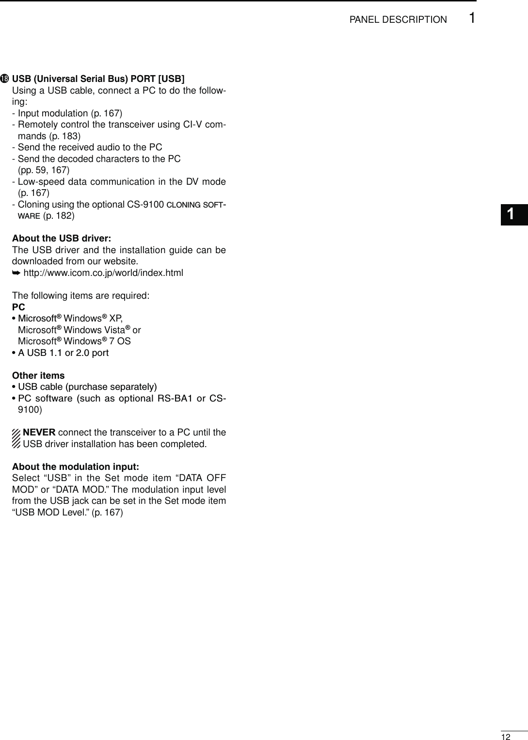
![oGROUND TERMINAL [GND] (p. 22) Connect this terminal to a ground to prevent electri-cal shocks, TVI, BCI and other problems.!0 TUNER CONTROL SOCKET [TUNER] (p. 29) Connect the control cable from an optional AH-4 HF/ 50 MHZ AUTOMATIC ANTENNA TUNER.!1 DATA1 JACK [DATA1] (p. 26, 168)± Connect a PC through the optional OPC-1529R DATA COMMUNICATION CABLE, for low-speed data communication in the DV mode. (p. 117)± Connect a GPS receiver through the optional OPC-1529R DATA COMMUNICATION CABLE, for GPS operation. (p. 121)!2 DATA2 SOCKET [DATA2] (pp. 26, 171) Connect a TNC (Terminal Node Controller), etc. for high speed data communications.!3 STRAIGHT KEY JACK [KEY] (p. 24) Connect a straight key or external electronic keyer output using a standard 1⁄4 inch plug.s;%,%#+%9= ON THE FRONT PANEL CAN BE USED FOR Astraight key or external electronic keyer. First you must turn OFF the internal electronic keyer in the Keyer Set mode. (p. 55)+_!4 ALC INPUT JACK [ALC] (p. 25) Connect to the ALC output jack of a non-Icom linear amplifier.!5 SEND CONTROL JACK [SEND] (p. 25) When transmitting, goes to ground to control an ex-ternal unit, such as a non-Icom linear amplifier.!6 ACCESSORY SOCKET [ACC] Connect control lines for external equipment such as a linear amplifier, an automatic antenna selector/ tuner, a TNC for data communications, etc. s3EEPAGEFORSOCKETINFORMATION!7 CI-V REMOTE CONTROL JACK [REMOTE] (pp. 26, 183)± Connect a PC, using the optional CT-17 CI-V LEVEL CONVERTER, for external control of the transceiver.± Use for transceive function with another Icom CI-V transceiver or receiver. When the transceive function is set to ON, changing the frequency, operating mode, etc. on the IC-9100 automatically changes those settings on other Icom transceivers or receivers, and vice versa. (p. 167)± Connect another IC-9100, using a mini plug cable*, for transceiver to transceiver cloning. * Purchase separately111PANEL DESCRIPTION!8!6 !7!5!4!3!2!1oN Rear panel (Continued)!0](https://usermanual.wiki/ICOM-orporated/318300.User-Manual-1/User-Guide-1415349-Page-20.png)
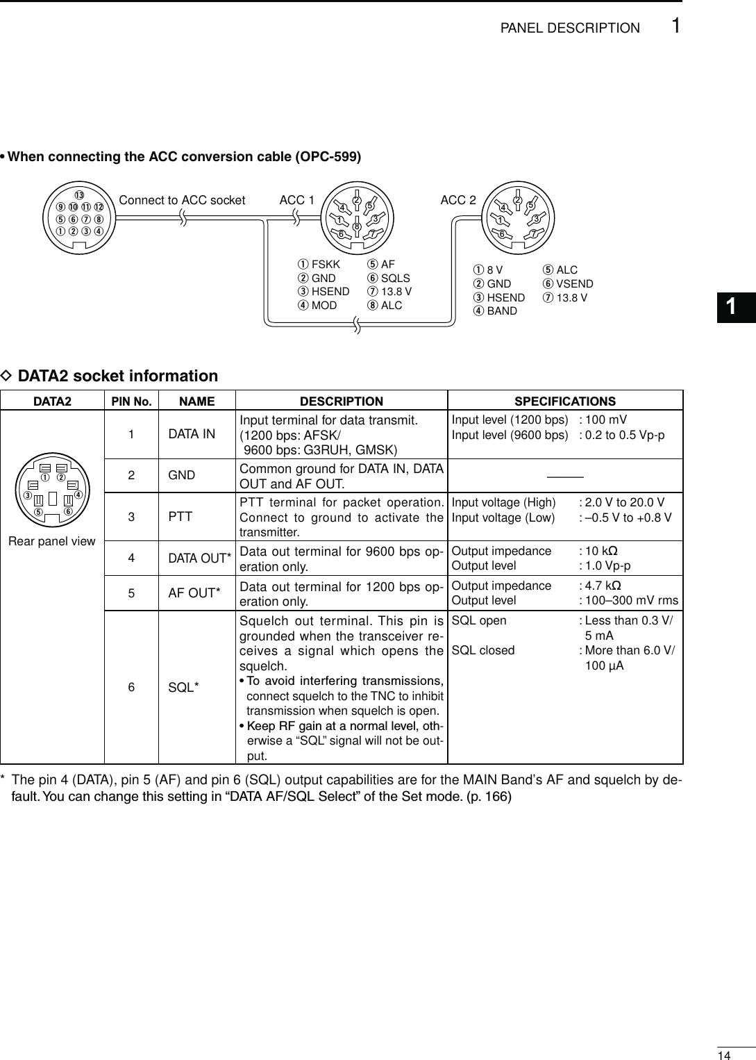
![131PANEL DESCRIPTIONN Rear panel (Continued)D!##SOCKETINFORMATIONs!##SOCKETACCPIN No.NAME DESCRIPTION SPECIFICATIONS12348765910 11 1213Rear panel viewColor refers to the cable strands of the supplied cable.q brownw rede oranger yellowt greeny blueu purpleio!0!1!2!3graywhiteblackpinklightbluelightgreen18 VRegulated 8 V output. Output voltageOutput current : 8 V ± 0.3 V: Less than 10 mA2 GND Connects to ground. ———3HSEND*1, 2 Input/out-put pin.An external equipment controls the transceiver.When this pin goes low, the transceiver trans-mits.Input voltage (High)Input voltage (Low)Current flow: 2.0 V to 20.0 V: –0.5 V to +0.8 V: Max. 20 mAThe transceiver outputs a low signal to control exter-nal equipment.Output voltage (Low)Current flow : Less than 0.1 V: Max. 200 mA4NC ——— ———5 BAND Band voltage output. Output voltage : 0 to 8 V6 ALC ALC voltage input. Control voltageInput impedance : –3 V to 0 V: More than 3.3 k˘7VSEND*1, 2 Input/out-put pin.An external equipment controls the transceiver.When this pin goes low, the transceiver trans-mits.Input voltage (High)Input voltage (Low)Current flow: 2.0 V to 20.0 V: –0.5 V to +0.8 V: Max. 20 mAThe transceiver outputs a low signal to control exter-nal equipment.Output voltage (Low)Current flow : Less than 0.1 V: Max. 200 mA8 13.8 V 13.8 V output when power is ON. Output current : Less than 1 A9 NC ——— ———10 FSKK #ONTROLS2449KEYING“High” level“Low” levelOutput current: More than 2.4 V: Less than 0.6 V: Less than 2 mA11 MOD Modulator input. Input impedanceInput level : 10 k˘: Approx. 100 mV rms12 AF*3AF detector output.Fixed level, regardless of the [AF] control position.Output impedanceOutput level : 4.7 k˘: 100 to 300 mV rms13SQL S*3Squelch output.Grounded when squelch opens.SQL openSQL closed : Less than 0.3 V/5 mA: More than 6.0 V/100 µA*1 When the SEND terminal controls the inductive load (such as a relay), a counter-electromotive force can cause the transceiver’s malfunction or damage. To prevent this, we recommend adding a switching diode, such as an “1SS133,” on the load side of the circuit to the counter-electromotive force absorption. When the diode is added, a switching delay of the relay may occur. Be sure to check its switching action before operation.eHSEND oruVSENDi13.8 VACC socketRelaySwitching diode To a non-Icom linear amplifiere*2 VSEND is used for the 144 MHz, 430 MHz, and 1200 MHz bands, and HSEND is used for the HF/50 MHz bands BYDEFAULT9OUCANCHANGETHISSETTINGINh63%.$3ELECTvOFTHE3ETMODEP*34HEPIN!&ANDPIN31,3OUTPUTCAPABILITIESAREFORTHE-!)."ANDS!&ANDSQUELCHBYDEFAULT9OUcan change this setting in “ACC AF/SQL Select” of the Set mode. (p. 166)](https://usermanual.wiki/ICOM-orporated/318300.User-Manual-1/User-Guide-1415349-Page-22.png)
![N,#$DISPLAY!2!0qtwqrweyyoo!1ui!0ui151PANEL DESCRIPTIONqFREQUENCY READOUTSDisplays the operating frequency.s7HENTHEQUICKTUNINGICONhZ” is displayed, the fre-quency changes in pre-set kHz or 1 MHz quick tuning steps. (p. 38)s7HENTHEQUICKTUNINGICONhZ” is not displayed, the fre-quency changes in 10 Hz or 1 Hz steps. (pp. 37, 39)wMULTI-FUNCTION METER INDICATION ±Displays the signal strength while receiving. ±Displays the relative output power, SWR, ALC or compression levels while transmitting. ±When the Meter Peak Hold function is ON, the peak level of a received signal strength or the output power is displayed for approximately 0.5 seconds.eANTENNA ICON (p. 158) Displays which antenna connector is selected for HF/50 MHz.sh!.4v APPEARS WHEN THE ;!.4= CONNECTOR IS SE-lected.sh!.4v APPEARS WHEN THE ;!.4= CONNECTOR IS SE-lected.r ANTENNA TUNER ICONS (pp. 159, 160) ±“” appears when the antenna tuner is TURNED/.h ” blinks during tuning. ±“” appears when the optional AH-4 external antenna tuner is connected to the [ANT1] con-nector, and [ANT1] is selected.tFUNCTION DISPLAY (p. 19)Shows the function of the function switches ([F1]–[F5]),Set mode items and IF passband width.yMEMORY CHANNEL READOUTSDisplays the selected memory channel.uSELECT MEMORY CHANNEL ICON±Appears when the selected memory channel is set as a select memory channel.(p. 151)±Appears when the repeater can be selected as the access repeater in the DR mode.(p. 100)iDR MODE ICON (p. 43)Appears when the DR mode is selected.oRIT/∂TX ICONS (pp. 69, 81)±“RIT” appears when the RIT function is turned ON.±“∂TX” appears when the ∂TX function is turned ON.±Shows the shift frequency of the RIT or ∂TX function.!0 VOICE SQUELCH CONTROL ICON (p. 146) Appears when the VSC (Voice Squelch Control) function is turned ON.!1 DUPLEX ICON (p. 65) “DUP+” appears when plus duplex, “DUP –” ap-pears when minus duplex (repeater) operation is selected.!2 KEY LOCK ICON (p. 77)Appears when the Key Lock function is turned ON.](https://usermanual.wiki/ICOM-orporated/318300.User-Manual-1/User-Guide-1415349-Page-24.png)
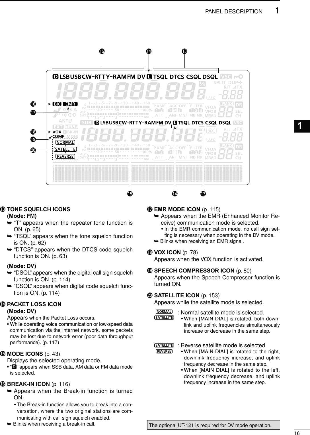
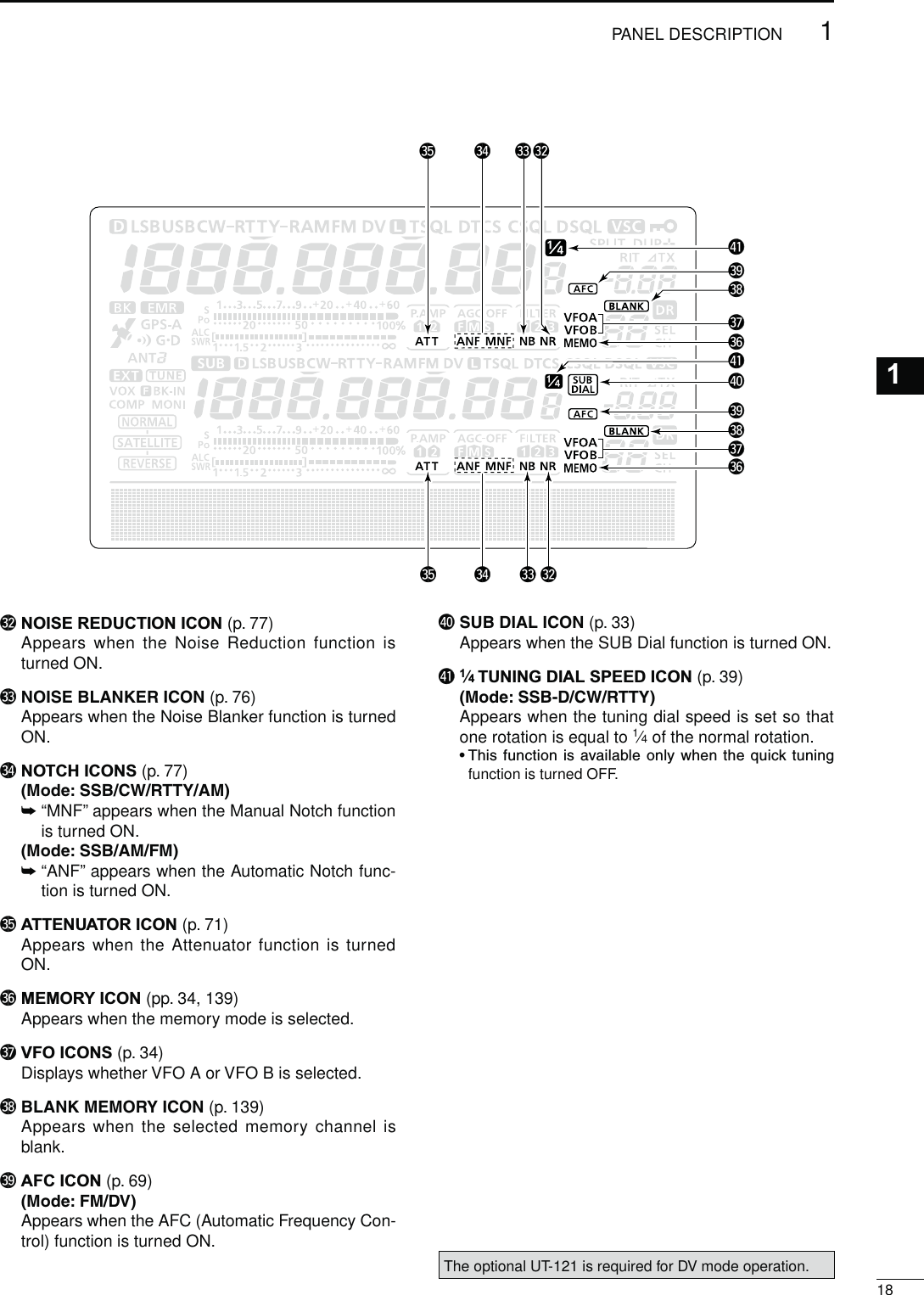
![171PANEL DESCRIPTIONN LCD display (Continued)@2 @1@3@4@6 @5@7#1@4@3@2@9@8#0@1 SPLIT ICON (p. 82)Appears when the Split function is turned ON.@2 DSP FILTER ICON (p. 73)Displays the selected IF filter.@3 AGC ICONS (p. 72)Displays the selected AGC time constant.shvFOR!'#FASTh vFOR!'#MIDDLEh vFOR!'#SLOW“-OFF” for AGC OFF. s)NTHE&-AND$6MODEh ” for AGC fast is fixed.@4 PREAMP ICON (p. 71)Appears when a preamplifier is turned ON. s)N(&-(ZFREQUENCYBANDEITHERh0!-0 ” or “P. AMP ” is displayed when the preamp 1 or preamp 2is ON.@5 GPS DATA COMMUNICATION ICON Appears while the GPS data communication func-tion is selected in the “GPS Out” item of the Set mode. (p. 168). s!'03DATAFROMTHE'03RECEIVERWHICHISCONNECTEDto the [DATA1] jack, is output to the [USB] port.@6 GPS TX ICON (p. 134) ±“GPS” appears when the GPS transmission mode is set to GPS. ±“GPS-A” appears when GPS transmission mode is set to GPS-A.@7 GPS ICON (p. 132)±Appears when a valid position data is received from a GPS receiver that is connected to the [DATA1] jack.±Blinks when an invalid data is received from the GPS receiver.@8 GPS ALARM ICON (p. 130) Appears when the GPS alarm function is turned ON.@9"2%!+).)#/.(p. 79) ±“F BK-IN” appears when the Full Break-in func-tion is turned ON. ±“BK-IN” appears when the Semi Break-in func-tion is turned ON.#0 MONITOR ICON (p. 81)Appears when the Monitor function is turned ON.#135")#/.(p. 33) Appears when the SUB Band setting mode is ON.](https://usermanual.wiki/ICOM-orporated/318300.User-Manual-1/User-Guide-1415349-Page-26.png)
![191PANEL DESCRIPTIONN&UNCTIONDISPLAYPush [MENU] to toggle the function display menu.s4HESETOFFUNCTIONSASSIGNEDTOTHEFUNCTIONSWITCHESchange according to the selected menu and operat-ing mode.s)NTHE$6MODE-menu 3) display can be selected after selecting menu 2.s)NTHE$2MODETHE$AND$DISPLAYSCANBESE-lected.Push to select the functions displayed in the display above switches ([F-1] to [F-5])s&UNCTIONSVARYDEPENDINGONTHEOPERATINGMODED--ENUDISPLAY-/$%33"AGC DUP COMP TBW SCP-/$%33"$AGC DUP 1 ⁄ 4 SCP<MODE> CWAGC DUP 1 ⁄ 4 +%9 SCP<MODE> RTTYAGC DUP 1 ⁄ 4 2449 SCP<MODE> AMAGC DUP SCP<MODE> FMAGC DUP AFC TON SCP<MODE> DVAGC DUP AFC DSQ SCPD--ENUDISPLAYSCAN MEM SWR TCON VSCD--ENUDISPLAY<MODE> DVCS CD R>CS UR DSETD$DISPLAY<MODE> DV (Only when “ ” is displayed.)CS CD R>CS UR DSETD$DISPLAY<MODE> DV (Only when “ ” is displayed.)SCAN SEL AFC DSQ TCON](https://usermanual.wiki/ICOM-orporated/318300.User-Manual-1/User-Guide-1415349-Page-28.png)
![222INSTALLATION AND CONNECTIONS2N3ELECTINGALOCATIONSelect a location for the transceiver that allows ade-quate air circulation, free from extreme heat, cold, or vibrations, and away from TV sets, TV antenna ele-ments, radios and other electromagnetic sources.The base of the transceiver has adjustable feet for desktop use. Set the feet to one of two angles, to meet your operating preference.N'ROUNDINGTo prevent electrical shock, television interference (TVI), broadcast interference (BCI) and other prob-lems, ground the transceiver using the GROUND ter-minal on the rear panel.For best results, connect a heaviest gauge wire or strap to a long ground rod. Make the distance between the [GND] terminal and ground as short as possible.RWARNING! NEVER connect the [GND] ter-minal to a gas or electric pipe, since the connection could cause an explosion or electric shock.[GND]N%LECTRONICKEYERANDMICROPHONECONNECTIONS(dot)(com)(dash) MICROPHONES (p. 30)HM-36 SM-50(Option)ELEC-KEYA straight key can also be connected. However, “Straight key” must be selected in the “Keyer Type” item of the Keyer Set mode. (p. 55)SM-30(Option)](https://usermanual.wiki/ICOM-orporated/318300.User-Manual-1/User-Guide-1415349-Page-31.png)
![232INSTALLATION AND CONNECTIONSPL-259 CONNECTOR INSTALLATION EXAMPLE TYPE-N CONNECTOR INSTALLATION EXAMPLESlide the coupling ring down. Strip the cablejacket and tin the shield.Slide the connectorbody on and solder it.Screw the couplingring onto the connec-tor body.Strip the cable asshown at left. Tin the center conductor.qwerSlide the nut, rubbergasket and clampover the coaxial cable, then cut the end of the cable evenly.Strip the cable andfold the braid backover the clamp.Tin the center con-ductor. Install thecenter conductor pinand solder it.Carefully slide theplug body into placealigning the centerconductor pin on thecable. Tighten the nut onto the plug body.qwer15 mm3 mm 6 mm30 mm10 mm (tin here)10 mm1–2 mmsolder soldertinCoupling ringNo spaceSolder holeBe sure the center conductor is the same height as the plug body.Clamp CenterconductorWasherNut Rubber gasket30 mm (9⁄8 in) 10 mm (3⁄8 in) 1–2 mm (1⁄16 in)N!NTENNACONNECTIONFor radio communications, the antenna is of critical importance, along with output power and receiver sen-sitivity. Select a well-matched 50 ø antenna and co-axial cable feedline. We recommend 1.5:1 or better of Voltage Standing Wave Ratio (VSWR) on your operat-ing bands. The transmission line should be a coaxial cable.When using a single antenna (for the HF/50 MHz band), use the [ANT1] connector.CAUTION: Protect your transceiver from lightning by using a lightning arrestor.!NTENNA372Each antenna is tuned for a specified frequency range and the SWR usually increases outside the range. When the SWR is higher than approximately 2.0:1, the transceiver automatically reduces the TX power to protect the final transistors. In that case, an antenna tuner is useful to match the transceiver and antenna. Low SWR allows full power for transmit-ting. The IC-9100 has an SWR meter to continuously monitor the antenna SWR.](https://usermanual.wiki/ICOM-orporated/318300.User-Manual-1/User-Guide-1415349-Page-32.png)
![242INSTALLATION AND CONNECTIONS2N2EQUIREDCONNECTIONSD2EARPANEL+_DC POWERSUPPLY(p. 27);-(Z!.4=(p. 158) ;-(Z!.4=(p. 158)PS-126Use the heaviest possible gauge wire or strap and make the connection as short as possible.Grounding prevents elec-trical shocks, TVI and other problems.GROUND (p. 22) STRAIGHT KEY ;-(Z!.4=(p. 158)The optional UX-9100 is required.(&-(Z!.4%..!(p. 158)Connection example:[ANT1] for 1.8–18 MHz bands antenna [ANT2] for 21–28 MHz bands antenna](https://usermanual.wiki/ICOM-orporated/318300.User-Manual-1/User-Guide-1415349-Page-33.png)
![D2EARPANEL252INSTALLATION AND CONNECTIONSN!DVANCEDCONNECTIONSD&RONTPANELHEADPHONESMICThe AFSK modulation signal can also be input to [MIC]. (p. 171)AH-4 (option)(p. 29)AH-2b (option)or long wirewithPREAMP (p. 71)(144 MHz and 430 MHz)144 MHz : AG-25 (option)430 MHz : AG-35 (option)External all-weather, mast-mounted preamplifiers are available.CAUTION: NEVER connect a power or SWR meter, or other device between the transceiver and preamplifier.;!,#=;3%.$= (p. 29)Used for connecting a non-Icom linear amplifier.;!.4=;!.4= (pp. 28, 29)Connect a linear amplifier, antenna selector, etc.EXTERNAL SPEAKER(MAIN/SUB)SP-23(option)](https://usermanual.wiki/ICOM-orporated/318300.User-Manual-1/User-Guide-1415349-Page-34.png)
![262INSTALLATION AND CONNECTIONS2N%XTERNALKEYPADCONNECTIONSTo pin eTo pin u1.5 kø±5%1.5 kø±5%2.2 kø±5%4.7 kø±5%S1(M1)S2(M2)S3(M3)S4(M4)EXTERNAL KEYPAD12345678(Front view)[MIC]EXTERNAL KEYPADConnect an external keypad for keyer memory control.When using a external keypad, select h+%9%23%.$vINTHEh%XTERNAL+EY-pad” item of the Set mode. (p. 167)N/PTIONALANDTHEEXTERNALUNITSCONNECTIONSDATA1 JACK (pp. 117, 121)Connect the optional OPC-1529R for low speed data communication using a PC and the transceiver, or for the GPS receiver connection.A third-party serial data communication software is required.DATA2 SOCKET(pp. 14, 171)ACC SOCKET(pp. 13, 171)Used for computer control and transceive operation.The optional CT-17 is re-quired when connecting a PC to [REMOTE].REMOTE JACK,53"#/..%#4/2 (p. 183)](https://usermanual.wiki/ICOM-orporated/318300.User-Manual-1/User-Guide-1415349-Page-35.png)
![N0OWERSUPPLYCONNECTIONSWhen operating the transceiver with AC power, use a power supply with 13.8 V DC output and a capacity of at least 24 Amperes.Refer to the diagrams below.CAUTION: Before connecting the DC power cable, check the following important items.Make sure:s4HE;0/7%2=SWITCHIS/&&s/UTPUTVOLTAGEOFTHEPOWERSOURCEISTO6when you use a non-Icom power supply.s$#POWERCABLEPOLARITYISCORRECTRed : Positive + terminalBlack : Negative _ terminal272INSTALLATION AND CONNECTIONSTransceiverGroundPS-126AC cableAC outlet To [DC 13.8V]+_DC power cableD#ONNECTINGTHE03$#0/7%23500,9D#ONNECTINGANON)COM$#0/7%23500,9N#ONNECTINGA$#POWERSUPPLYSupplied DC power cableAC cableAC outletTransceiverTo [GND]A DC power supply6at least 24 ARed BlackTo [DC 13.8V]To [DC 13.8V]For European versionsTransceiverGroundConnect topower supply](https://usermanual.wiki/ICOM-orporated/318300.User-Manual-1/User-Guide-1415349-Page-36.png)
![282INSTALLATION AND CONNECTIONS2N,INEARAMPLIlERCONNECTIONSD#ONNECTINGTHE)#0707%52/EXCITER11&2Remote control cable (supplied with the IC-PW1/PW1EURO)ACC cable (supplied with the IC-PW1/PW1EURO)To anantenna [ACC1][REMOTE][ANT]IC-PW1/EUROAC outlet(Non-European versions: 100–120/200–240 V European version : 230 V)[INPUT1]7-pin side[REMOTE]Coaxial cable(supplied with the IC-PW1/PW1EURO)[ANT2]Transceiver[ACC][GND]Ground[ANT1][INPUT2]*Purchase separately, and connect to [INPUT2], if necessary.[GND]OPC-599Coaxial cable*](https://usermanual.wiki/ICOM-orporated/318300.User-Manual-1/User-Guide-1415349-Page-37.png)
![292INSTALLATION AND CONNECTIONSN Linear amplifier connections (Continued)D#ONNECTINGANON)COMLINEARAMPLIlERR WARNING!s3ETTHETRANSCEIVEROUTPUTPOWERANDLINEARAMPLIlER!,#OUTPUTLEVELAFTERREFERRINGTOTHELINEARAMPLIlERIN-struction manual.s4HE!,#INPUTLEVELMUSTBEINTHERANGE6TOn64HETRANSCEIVERDOESNOTACCEPTAPOSITIVEVOLTAGE.ONmatched ALC and RF power settings could overheat or damage the linear amplifier.s4HE)#3%.$TERMINAL!##CONNECTORPINISRATEDAT6!$#)FTHISVALUEISEXCEEDEDALARGERexternal relay must be used.50 ø coaxial cableTo an antennaNon-Icom linear amplifierRF OUTPUTTransceiver[GND] [ALC]GNDGround[ANT1]N%XTERNALANTENNATUNERCONNECTIOND#ONNECTINGTHE!(The AH-4 must be connected to [ANT1].TransceiverControl cableGround Ground[ANT1] AH-4Long wire or optional AH-2b[TUNER]Coaxial cable (from the AH-4)ALCSEND[SEND]RF INPUT](https://usermanual.wiki/ICOM-orporated/318300.User-Manual-1/User-Guide-1415349-Page-38.png)
![302INSTALLATION AND CONNECTIONS2N-ICROPHONECONNECTORINFORMATION(Front panel view)y GND (PTT ground)t PTTr Main band’s squelch switchq Microphone inputw +8 V DC outpute Frequency up/downi Main band’s AF output (varies with [AF])GND(Microphone ground)u[MIC]0IN.O FUNCTION DESCRIPTIONw+8 V DC output Max. 10 mAeFrequency up GroundFrequency down Ground through 470 ˘rSquelch open “Low” levelSquelch closed “High” levelCAUTION: DO NOT short pin 2 to ground as this can damage the internal 8 V regulator. DC voltage is applied to pin 1 for microphone operation. Use caution when using a non-Icom microphone.N-ICROPHONESDHM-36qwD SM-50 (Option)qwreqUP/DOWN SWITCHES [UP]/[DN] Push to change the frequency or memory channel.s7HILEHOLDINGDOWNTHEFREQUENCYORMEMORYCHANNELnumber continuously increases or decreases.s7HILEINTHESPLITFREQUENCYMODEANDHOLDINGDOWN[XFC], push to change the transmit frequency.s4HE;50=;$.=SWITCHCANBEUSEDASAKEYPADDLEIFthe “MIC Up/Down Keyer” item setting is “ON” in the Keyer Set mode. In such case, the frequency and mem-ory channel cannot be changed using the [UP]/[DN] switches. (p. 55)s9OUCANSETTHEDOTDASHPOLARITYOFTHE;50=;$.=SWITCHin the “Paddle Polarity” item of the Keyer Set mode. When “Normal” is selected, [UP] sends a dash, and [DN] sends a dot. (p. 55)wPTT SWITCH (OLDDOWNTOTRANSMITRELEASETORECEIVEePTT LOCK SWITCH (available on only the SM-50)Push to toggle between transmit and receive.rLOW CUT SWITCH (available on only the SM-50) Push to cut out the low frequency components of input voice signals.](https://usermanual.wiki/ICOM-orporated/318300.User-Manual-1/User-Guide-1415349-Page-39.png)
![[RF/SQL]: 12 o’clock[MIC GAIN]: 12 o’clock[NR]: Max. CCW[CW PITCH]: 12 o’clock[NOTCH]: 12 o’clock[RF POWER]: Max. CW;+%930%%$=: 10–12 o’clock[AF]: Max. CCWN"EFORElRSTAPPLYINGPOWERBefore turning ON your transceiver for the first time,make sure all connections required for your system are complete by reviewing them in Section 2 of this manual.After all connections have been made, set controls and switches as shown in the illustration below.CW : Max. clockwiseCCW : Max. counterclockwise331"!3)#/0%2!4)/.[POWER] [F-INP ENT] [VFO/MEMO]N4URNING/.0ARTIALRESETTINGFirst time to Power ON:Reset the transceiver using the following procedure.A partial resetting CLEARS the operating parame-ters to their default values (VFO frequency, VFO settings, menu group’s contents) without clearing certain data. See page 181 for details.qMake sure the transceiver’s power is OFF.wWhile holding down both [F-INP ENT] and [VFO/MEMO], push [POWER] to turn ON the transceiver. s$URING STARTUP THE TRANSCEIVER DISPLAYSh0!24)!,RESET,” then its initial VFO frequencies when resetting is complete. s)FYOUOPERATETHETRANSCEIVERBEFOREh0!24)!,2%3%4vdisappears, the resetting will be cancelled.e Change the Set mode settings to suit your operat-ing needs. (p. 161)Normal Power ON:Push [POWER] to turn ON the transceiver.Power OFF:Hold down [POWER] for 1 second to turn OFF the transceiver.AGC DUP COMP TBW SCPM1PARTIAL RESETInitial VFO display](https://usermanual.wiki/ICOM-orporated/318300.User-Manual-1/User-Guide-1415349-Page-40.png)
![323BASIC OPERATION3323N-!).AND35""ANDSThe IC-9100 can operate on the HF/50 MHz, 144 MHz, 430 MHz and 1200 MHz* frequency bands. These fre-quency bands can be assigned to the MAIN and SUB Bands for operating convenience.The MAIN and SUB Bands cannot simultaneously oper-ate on frequency bands within the HF/50 MHz band. For example, if the MAIN Band is set to operate on any fre-quency within the HF/50MHz band, the SUB Band can simultaneously receive on only the 144 MHz, 430 MHz and 1200 MHz* frequency bands, or visa versa.*The optional UX-9100 is required for the 1200 MHz fre-quency band operation.Both MAIN and SUB Bands have independent features.MAIN Band : Used for both transmitting and receiving. The MAIN Band area is in the upper half of the LCD display.SUB Band : Used for only receiving. The SUB Band area is in the lower half of the LCD display.!BOUTTRANSMITTING9OUCANTRANSMITONONLYTHE-!)."ANDNOTONTHESUB Band. However, while operating in the Satellite mode, you can transmit on the SUB Band.D-!).35""ANDSELECTIONThe LCD display shows both the MAIN and SUB Band frequencies. Both Bands can receive signals simulta-neously, but not on the same frequency band. Set the frequency band you want to transmit or be called on, as the MAIN Band.±Push [MAIN/SUB] to toggle the MAIN and SUB Bands.SUB Band display (146.520 MHz FM)MAIN Band display (14.100 MHz USB)PushSUB Band display (14.100 MHz USB)MAIN Band display (146.520 MHz FM)[MAIN/SUB]D35""ANDDISPLAYThe SUB Band display can be turned OFF to simplify operation.±Hold down [SUB] for 1 second to turn the SUB Band display ON or OFF. s.OTHINGISDISPLAYEDONTHE35""ANDDISPLAYWHENITISturned OFF.[SUB]SUB Band displayWhen the SUB Band display is OFF](https://usermanual.wiki/ICOM-orporated/318300.User-Manual-1/User-Guide-1415349-Page-41.png)
![333BASIC OPERATIOND4HE35"$IALFUNCTIONThe [SUB DIAL] control’s tuning Band and frequency steps differ, depending on the combination of the SUB Dial function and SUB Band setting mode, and the sta-tus of the quick tuning function.±Push [SUB DIAL] to turn the SUB Dial function ON or OFF.sh ” appears when the function is ON.!BOUTTHE4UNED"ANDWITHTHE;35"$)!,=CONTROL35"$IALFUNCTION(“ ” appears when ON is selected.)35""ANDSETTING(“ ”appears when ON is selected.)4UNED"ANDON ON SUB Band*ON OFF SUB Band*OFF ON SUB Band†OFF OFF MAIN Band†* The frequency changes in 1 Hz, 10 Hz, 1 MHz or pre-set kHz steps, depending on the quick tuning step setting. (p. 38)† The frequency changes in the programmed kHz steps, even if the quick tuning is OFF.[SUB DIAL] [SUB DIAL] controlAppears when the SUB Dial function is ON.D35""ANDSETTINGMODEOPERATIONNormally, tuning, operating mode selection, memory channel selection and programming, are made for the MAIN Band.When the SUB Band setting mode is ON, the settings and selections are for only the SUB Band.s9OUCANNOTTRANSMITONTHE35""ANDs9OUCANNOTMAKE-AIN"ANDSETTINGS±Push [SUB] to turn the SUB Band setting mode ON or OFF.sh” appears when the SUB Band setting mode is ON.[SUB]AppearsThe SUB Band setting mode is OFF.PushThe SUB Band setting mode is ON.Disappears](https://usermanual.wiki/ICOM-orporated/318300.User-Manual-1/User-Guide-1415349-Page-42.png)
![343BASIC OPERATION3N6&/DESCRIPTION4HE)#HASTWO6&/Sh!vANDh"vFOREACH-!).and SUB Bands, and are convenient for quickly select-ing two frequenciesORSPLITFREQUENCYOPERATION9OUcan use either VFO to call up a frequency and operat-ing mode.VFO is an abbreviation of Variable Frequency Oscil-lator.D 3ELECTINGTHE6&/!"±Push [A/B] to switch between the VFO A and VFO B.sh6&/!vORh6&/"vAPPEARSWHENTHE6&/ISSELECTEDD 6&/EQUALIZATION±Hold down [A/B] for 1 second to equalize the data in both VFOs. sBEEPSSOUNDWHENTHEEQUALIZATIONISCOMPLETECONVENIENT!5SETWO6&/SASQUICKMEMORIESWhen you find a new station, but wish to continue searching, the dual VFO system can be used for quick memory storage.qHold down [A/B] for 1 second to store the displayed contents into the undisplayed VFO.w Continue searching for stations.ePush [A/B] to show the stored contents on the un-displayed VFO.rTo continue searching for stations, push [A/B] again to show the displayed VFO.N3ELECTING6&/MEMORYMODE±Push [VFO/MEMO] to switch between the VFO and memory modes.sh6&/ !vORh6&/ "vAPPEARSWHENIN THE 6&/MODEor “MEMO” and the selected memory channel number appear when in the memory mode.s(OLDING DOWN ;6&/-%-/= FOR SECOND COPIES THEcontents of the selected memory channel into the dis-played VFO. (p. 142)Memory iconThe selected VFO icon[A/B]The selected VFO iconq Hold downe PushDisplayed VFOUndisplayed VFO[VFO/MEMO]Memory channel number](https://usermanual.wiki/ICOM-orporated/318300.User-Manual-1/User-Guide-1415349-Page-43.png)
![353BASIC OPERATION"!.$ REGISTER 1 REGISTER 2 REGISTER 31.8 MHz 1.900000 MHz CW 1.910000 MHz CW 1.915000 MHz CW3.5 MHz 3.550000 MHz LSB 3.560000 MHz LSB 3.580000 MHz LSB7 MHz 7.050000 MHz LSB 7.060000 MHz LSB 7.020000 MHz CW10 MHz 10.120000 MHz CW 10.130000 MHz CW 10.140000 MHz CW14 MHz 14.100000 MHz USB 14.200000 MHz USB 14.050000 MHz CW18 MHz 18.100000 MHz USB 18.130000 MHz USB 18.150000 MHz USB21 MHz 21.200000 MHz USB 21.300000 MHz USB 21.050000 MHz CW24 MHz 24.950000 MHz USB 24.980000 MHz USB 24.900000 MHz CW28 MHz 28.500000 MHz USB 29.500000 MHz USB 28.100000 MHz CW50 MHz 50.100000 MHz USB 50.200000 MHz USB 51.000000 MHz FM144 MHz 146.520000 MHz FM 145.100000 MHz FM 145.200000 MHz FM430 MHz 446.000000 MHz FM 440.100000 MHz FM 440.200000 MHz FM1200 MHz*11294.500000 MHz FM 1295.100000 MHz FM 1294.200000 MHz FMGeneral*215.000000 MHz USB 15.100000 MHz USB 15.200000 MHz USB*1 The optional UX-9100 is required for the 1200 MHz frequency band operation.*2;'%.%s=SELECTSTHEGENERALCOVERAGEBANDD5SINGTHEBANDSTACKINGREGISTERSThe triple band stacking register provides 3 memo-ries for each band key to store frequencies and oper-ating modes.This function is convenient when you operate 3 operat-ing modes on one frequency band.For example, one register can be used for a CW fre-quency, another for an SSB frequency and the other ONEFORAN2449FREQUENCY)FABANDKEYOR;'%.%s=ISPUSHEDONCETHELASTused frequency and operating mode are called up. When the key is pushed again, another stored fre-quency and operating mode are called up.* If you are using a frequency band other than HF/50 MHz, you can call up the HF/50 MHz frequency band by pushing THEBANDKEYS;=TO;=OR;'%.%s=See the table below for a list of the available frequency bands and their default frequency and mode settings.N3ELECTINGAFREQUENCYBANDThe frequency band you want to use can be selected in the MAIN and SUB Bands.Before changing the frequency band on the SUB Band, push [SUB] to turn ON the SUB Band setting mode.In addition to the HF/50 MHz, 144 MHz and 430 MHz frequency bands, the IC-9100 can operate on the 1200 MHz frequency band*1.qHold down [BAND](MAIN/SUB) for 1 second sev-eral times until the desired frequency of the bands that are stored in the MAIN or SUB Band, which-ever you selected.w To call up the previously selected frequency and op-ERATINGMODEPUSHABANDKEYOR;'%.%s=IFTHEHF/50 MHz frequency band was selected in step q,ORPUSH;'%.%s=IFTHE144 MHz, 430 MHz or 1200 MHz frequency band*1 was selected.[BAND](MAIN/SUB) Band keysNOTE: The same frequency band cannot be simul-taneously selected in both MAIN and SUB Bands.The frequency band, selected in either the MAIN or SUB Band, cannot be selected on the other Band.](https://usermanual.wiki/ICOM-orporated/318300.User-Manual-1/User-Guide-1415349-Page-44.png)
 for 1 second sev-eral times until a HF/50 MHz frequency band is dis-played.w0USHABANDKEY;=TO;=OR;'%.%s=s4HEPREVIOUSLYSELECTEDFREQUENCYANDOPERATINGMODEare called up as the first band stacking register of that frequency band.e Select a frequency and an operating mode, and then push the band key.s4HESELECTEDFREQUENCYANDMODEAREMEMORIZEDASthat frequency band’s first band stacking register.r Select another frequency and operating mode, and then push the band key.s4HESELECTEDFREQUENCYANDMODEAREMEMORIZEDASthat frequency band’s second band stacking register.t Select another frequency and operating mode, and then push the band key.s4HESELECTEDFREQUENCYANDMODEAREMEMORIZEDASthat frequency band’s third band stacking register.y The first band stacking register set in step e, is called up.s7HENTHEFREQUENCYBANDKEYISPUSHEDTHEMEMO-rized triple band stacking registers are sequentially called up.&REQUENCYBAND-(Zq Hold down [BAND](MAIN/SUB) for 1 second sev-eral times until a 144 MHz, 430 MHz or 1200 MHzfrequency band is displayed.s4HEPREVIOUSLYSELECTEDFREQUENCYANDANOPERATINGmode are called up as the first band stacking register of that frequency band.w Select a frequency and an operating mode, and THENPUSH;'%.%s=s4HESELECTEDFREQUENCYANDMODEAREMEMORIZEDASthat frequency band’s first band stacking register.e Select another frequency and operating mode, and THENPUSH;'%.%s=s4HESELECTEDFREQUENCYANDMODEAREMEMORIZEDASthat frequency band’s second band stacking register.r Select another frequency and operating mode, and THENPUSH;'%.%s=s4HESELECTEDFREQUENCYANDMODEAREMEMORIZEDASthat frequency band’s third band stacking register.t The first band stacking register set in step w, is called up.s7HEN;'%.%s=ISPUSHEDTHEMEMORISEDTRIPLEBANDstacking registers are sequentially called up.The optional UX-9100 is required for 1200 MHz frequency band operation.Hold downPushPushPushHold down;%XAMPLE= 14 MHz frequency band;%XAMPLE= 430 MHz frequency bandPushPushPush](https://usermanual.wiki/ICOM-orporated/318300.User-Manual-1/User-Guide-1415349-Page-45.png)
![373BASIC OPERATIONN&REQUENCYSETTING9OUCANSELECTTHETRANSCEIVERSFREQUENCYBYUSING[MAIN DIAL], or you can enter it using the keypad.D4UNINGWITH;-!).$)!,=q Select the desired frequency band.s(OLDDOWN;"!.$=-!).35"FORSECONDSEVERALtimes until the desired frequency band is displayed.s0USHTHEDESIREDBANDKEYONTHEKEYPADOR;'%.%s=1–3 times. 3 different frequencies on each frequency band can be selected with the band key. (See previous page “Using the band stacking registers.”)s4HEDEFAULTTUNINGSTEPDIFFERSDEPENDINGONTHEOPERAT-ing mode. 33"#72449(Z AM : 1 kHz (“Z” is displayed) FM/DV : 10 kHz (“Z” is displayed)w Rotate [MAIN DIAL] to set the desired frequency.If the Dial Lock function is ON, “ ” is displayed, and [MAIN DIAL] does not function.In this case, hold down [SPEECH/LOCK] for 1 sec-ond to turn OFF the lock function. (p. 77)When “LOCK/SPEECH” is selected in the “[SPEECH/LOCK] SW” item of the Set mode, push-ing [SPEECH/LOCK] turns OFF the lock function. (see p. 164 for details)D$IRECTFREQUENCYENTRYWITHTHEKEYPADThe transceiver has a keypad for direct frequency entry, as described below.q Push [F-INP ENT] to enter frequencies with the keypad. s!LLFREQUENCYDIGITSDISAPPEARw Push the numeric keys to input the desired fre-quency.s0USH;'%.%s=TOINPUTAhvDECIMALPOINTBETWEENTHE1 MHz digits and 100 kHz digits.e Push [F-INP ENT] to set the input frequency.s4OCANCELTHEINPUTPUSH;%8)43%4=BEFOREPUSHING[F-INP ENT].NOTE: The frequency band, selected in either the MAIN or SUB Band, cannot be selected on the other Band.Keypad[EXAMPLE]-(Z-(ZK(Z-(Z-(Z-(Z¶-(ZBand keys[MAIN DIAL]](https://usermanual.wiki/ICOM-orporated/318300.User-Manual-1/User-Guide-1415349-Page-46.png)
![383BASIC OPERATION3D1UICK4UNINGFUNCTIONThe operating frequency can be changed in 1 kHz or 1 MHz steps for quick tuning.Select the desired tuning step in each operating fre-quency band and mode.q Push [TS] to select the 1 kHz or 1 MHz Quick Tun-ing function step, or turn it OFF.s7HILETHEQUICKTUNINGICONhZ,” is displayed above the 1 kHz or 1 MHz digit, the frequency will be changed in 1 kHz or 1 MHz steps.s7HENTHEFUNCTIONIS/&&THEFREQUENCYWILLBECHANGEDin 10 Hz steps.w Rotate [MAIN DIAL] to change the frequency in the selected steps.NOTE:s4OTURN/&&THE1UICK4UNINGFUNCTIONPUSH;43=again. (“Z” disappears)s7HENTHE1UICK4UNINGFUNCTIONIS/&&THEFRE-quency will be changed in 10 Hz steps.D3ELECTINGhK(ZvSTEPWhen the 1 kHz quick tuning is selected, the frequency can be changed in the selected “kHz” steps.The MAIN and SUB Bands use the common “kHz” tun-INGSTEP9OUCANSELECTITINBOTH"ANDSq Push [TS] to turn ON the Quick Tuning function.shZ” appears.w Hold down [TS] for 1 second to display the “TS” screen to select the quick tuning step.eSelect the desired operating mode.r Rotate [MAIN DIAL] to select the desired “kHz” step.sANDK(ZAREselectable. s(OLDDOWN;&=FORSECONDTORETURNTOTHEDEFAULTSET-ting, if desired.t Repeat steps e and r to select quick tuning steps for other modes.yPush [TS] to exit the “TS” screen.NOTE: To display the “TS” screen, the Quick Tuning function must be turned ON first.[TS][MAIN DIAL]Appears[TS][F-3]Mode selection [MAIN DIAL]](https://usermanual.wiki/ICOM-orporated/318300.User-Manual-1/User-Guide-1415349-Page-47.png)
![393BASIC OPERATIONN Frequency setting (Continued)D3ELECTING(ZSTEP9OUCANCHANGETHEFREQUENCYIN(ZSTEPSFORFINEtuning.q Push [TS] to turn OFF the Quick Tuning function.w Hold down [TS] for 1 second to turn the 1 Hz tuning step ON or OFF.NOTE:s7HEN2)4ANDOR∂TX are used, they also tune in 1 Hz tuning steps.s4HEFREQUENCYCHANGESIN(ZSTEPSWHENTHE[UP]/[DN] switches of the microphone are used for frequency tuning (if the quick tuning function is not selected.)D!UTOTUNINGSTEPFUNCTIONWhen you rotate [MAIN DIAL] rapidly, the tuning speed can automatically accelerate, depending on the “MAIN DIAL Auto TS” option in the Set mode.q Hold down [MENU] for 1 second to enter the Set mode.w Push [Y](F-1) or [Z](F-2) to select “MAIN DIAL Auto TS.”e Rotate [MAIN DIAL] to select the HIGH or LOW tuning speed acceleration, or to turn OFF the func-tion. s()'(7HENTHETUNINGSTEPISSETTOK(ZORsmaller steps, the tuning speed is approxi-mately five times faster. When the tuning step is set to 5 kHz or larger steps, the tuning speed is approxi-mately two times faster. (default) s,/7!PPROXIMATELYTWOTIMESFASTER s/&& !UTOTUNINGSTEPISTURNED/&&s(OLDDOWN;#,2=&FORSECONDTORESETTOTHEDE-fault value.rPush [MENU] to save, and exit the Set mode.D1⁄4TUNINGSTEPFUNCTION-ODE33"$#72449The dial speed is reduced to 1⁄4 of the normal speed when the 1⁄4 tuning function is ON, for finer tuning con-trol.9OUCANSETTHE1⁄4 tuning function in each operating mode.This function is selectable only when the quick tuning function is turned OFF.q Push [MENU] to display the “M1” screen (menu 1).w Push [1⁄4](F-3) to turn the 1⁄4 tuning function ON or OFF.sh ” appears when the 1⁄4 tuning function is ON.[TS][MAIN DIAL]1 Hz step indication[][][MAIN DIAL][MENU]HIGH (default)Ù44ÚHIGHSET MAIN DIAL Auto TS[1⁄4][MENU]Appears](https://usermanual.wiki/ICOM-orporated/318300.User-Manual-1/User-Guide-1415349-Page-48.png)
![413BASIC OPERATIONN Frequency setting (Continued)D"ANDEDGEWARNINGBEEP9OUCANHEARABEEPTONEWHENYOUTUNEINTOOROUTof an amateur band’s frequency range. A regular beep sounds when you tune into a range, and an lower tone error beep sounds when you tune out of a range.q Hold down [MENU] for 1 second to enter the Set mode.w Push [Y](F-1) or [Z](F-2) to select “Band Edge Beep.”e Rotate [MAIN DIAL] to select the desired band edge warning beep setting. s/&& "ANDEDGEBEEPIS/&& s/.$EFAULT 7HEN YOU TUNE INTO OR OUT OFthe default amateur band’s fre-quency range, a beep sounds. (default) s/.5SER 7HEN YOU TUNE INTO OR OUT OFa user programmed amateur band’s frequency range, a beep sounds. s/.5SER487HEN YOU TUNE INTO OR OUT OFa user programmed amateur band’s frequency range, a beep sounds. Also transmission is in-hibited outside the programmed range.s(OLDDOWN;#,2=&FORSECONDTORESETTOTHEDE-fault value.rPush [MENU] to save, and exit the Set mode.The beep output level can be set in the “Beep Level” item of the Set mode. (p. 161)!BOUTTHEUSERBANDEDGEFREQUENCIES7HENh/.5SERvORh/.5SER48vISSELECTEDINthe “Band Edge Beep” item, a total of 30 band edge frequencies can be programmed in the “User Band Edge” item. See the next page for details.If “OFF” or “ON (Default)” is selected, the “User Band Edge” item does not appear in the Set mode.[][][MAIN DIAL][MENU]ON (Default)Ù 6ÚON(Default)SET Band Edge BeepON (User) selectionÙ 6ÚON(User)SET Band Edge Beep[User Band Edge] itemÙ 7ÚDEF EDTSET User Band EdgePush](https://usermanual.wiki/ICOM-orporated/318300.User-Manual-1/User-Guide-1415349-Page-50.png)
![423BASIC OPERATION3D0ROGRAMMINGTHEUSERBANDEDGE7HENh/.5SERvORh/.5SER48vISSELECTEDINthe “Band Edge Beep” item, the “User Band Edge” item appears in the Set mode.A total of 30 band edge frequencies can be pro-grammed in the “User Band Edge” item.NOTE:s!LLFREQUENCYRANGESARESET TODEFAULTSOYOUshould delete or change them to add the desired band edge frequency.s0ROGRAMEACHCHANNELFROMLEFTTORIGHTANDEACHfrequency must be higher than the preceding fre-quency.s4HEFREQUENCYTHATISDUPLICATEDOROUTOFANAMA-teur band, cannot be programmed.q Hold down [MENU] for 1 second to enter the Set mode.w Push [Y](F-1) or [Z](F-2) to select “Band Edge Beep.”e Rotate [MAIN DIAL] to select either “ON (User)” or h/.5SER48vOPTIONr Push [Z](F-2) to select “User Band Edge.”t Push [EDT](F-4) to display the “EDG” screen (band edge program).y Push [Y](F-1) or [Z](F-2) to select the desired band edge.s(OLDINGDOWN;Y](F-1) or [Z](F-2) continuously selects the band edges.s0USH;Ω≈](F-3) to select the upper or lower band edge frequency entry status.s(OLDDOWN;$%,=&FORSECONDTODELETETHESE-lected band edge.s0USH;).3=&TOINSERTANEWBLANKBANDEDGEu Input the desired frequency with the keypad, then push [F-INP ENT].s0USH;'%.%s=to input decimal point (“.”) between the MHz and kHz digits.iPush [MENU] to save.oPush [MENU] again to exit the Set mode.4ORESETTHEBANDEDGEFREQUENCIESIf you want to reset the band edge frequencies to their default (initial) value, select the “User Band Edge” item, then hold down [DEF](F-3) for 1 second.The band edge initialize screen appears, then hold DOWN;9%3=&FORSECONDTORESETALLBANDEDGEfrequency settings to their default values.ON (User) setting in the“Band Edge Beep” itemÙ 6ÚON(User)SET Band Edge Beep“User Band Edge” itemÙ 7ÚDEF EDTSET User Band Edge“EDG” screen 1INS DELEDG1.800.000- 1.999.999“User Band Edge” itemÙ 7ÚDEF EDTSET User Band EdgeBand edge initialize screenNOYESSET Initialize Edges?Ù 7ÚDEF EDTSET User Band EdgeHold down[][][][] [DEL] [MAIN DIAL][MENU]KeypadPushPushHold down](https://usermanual.wiki/ICOM-orporated/318300.User-Manual-1/User-Guide-1415349-Page-51.png)
![433BASIC OPERATIONN/PERATINGMODESELECTIONThe usable operating modes in the IC-9100 are listed to the right.9OUCANSELECTTHEDESIREDOPERATINGMODEBYPUSH-ing the mode switch.See the diagram to the right for the order of selection.9OU CAN MUTE THE MICROPHONE SIGNALS WHEN THEdata mode is selected, depending on the “DATA MOD” option in the Set mode (p. 167).s3ELECTINGTHE33"MODE±Push [SSB] to select the USB or LSB mode. sh,3"vORh53"vAPPEARSs7HENOPERATINGABOVE-(Z53"ISSELECTEDlRSTwhen operating below 10 MHz, LSB is selected first. s0USH;33"=AGAINTOTOGGLEBETWEEN53"AND,3"s!FTER 53" OR ,3"ISSELECTEDHOLDDOWN ;33"=FOR1 second to select the data mode. (“D” appears)s)NTHEDATAMODEPUSH;33"=TORETURNTOTHENORMALSSB mode.s3ELECTINGTHE#72449MODE±0USH;#72449=TOSELECTTHE#7OR2449MODE sh#7vORh2449vAPPEARSs0USH ;#72449= AGAIN TO TOGGLE BETWEEN #7 AND2449s!FTER#7OR2449ISSELECTEDHOLDDOWN;#72449=for 1 second to toggle between normal and reverse modes.h#72vORh24492vAPPEARSs3ELECTINGTHE!-&-MODE±Push [AM/FM] to select the AM or FM mode. sh!-vORh&-vAPPEARSs0USH;!-&-=AGAINTOTOGGLEBETWEEN!-AND&-s!FTER !-OR&- ISSELECTEDHOLD DOWN;!-&-= FOR1 second to select the data mode. (“D” appears)s)NTHEDATAMODEPUSH;!-&-=TORETURNTOthe normal AM or FM mode.NOTE:s)NTHE!-MODEYOUCANTRANSMITONONLYTHEHF/50MHz frequency bands.s4HE!-MODECANNOTBESELECTEDONTHEMHz frequency band.s3ELECTINGTHE$6MODEINCLUDING$2MODE±0USH;$6s$2=TOSELECTTHE$6MODE sh$6vAPPEARS s$6MODEDIGITALVOICELOWSPEEDDATACOMMUNICA-tion) allows you to exchange the text message and call sign, and transmit a position data with a third-party GPS receiver.±(OLD DOWN ;$6s$2= TO TURN THE $2 $34!2®Repeater) mode operation ON or OFF.s“DV” and “ ” appears.s4HE$6MODEISAUTOMATICALLYSELECTEDWHENTHE$2mode is ON. s$2$34!22EPEATERMODEALLOWSYOUTOUSEARE-peater list to operate a D-STAR repeater simply.The optional UT-121 is required for DV mode operation.Mode switchesUSBUSBAMAMLSB LSBCW-R CW RTTY RTTY-RFM FMDV DR: Push momentary: Hold down for 1 seconds5SABLEOPERATINGMODES-ODESWITCH /PERATINGMODE;33"= USB USB DataLSB LSB Data[CW/RTTY] CW CW Reverse2449 24492EVERSE[AM/FM] AM AM DataFM FM Data;$6s$2= DVINFORMATION!The DV mode can be selected in either MAIN or SUB band. If you select the DV mode in both Bands, the transceiver cannot receive on the SUB Band.](https://usermanual.wiki/ICOM-orporated/318300.User-Manual-1/User-Guide-1415349-Page-52.png)
![N3QUELCHANDRECEIVE2&SENSITIVITYAdjusts the RF gain and squelch threshold level. The squelch removes noise output to the speaker when no signal is received (closed squelch).s4HESQUELCHISPARTICULARLYEFFECTIVEFOR!-AND&-BUTCANalso be used in other modes.s4HETOOCLOCKPOSITIONISRECOMMENDEDFORthe most effective use of the [RF/SQL] control.s;2&31,=CANOPERATEASONLYAN2&GAINCONTROLSquelchis fixed open) or only a squelch control (RF gain is fixed at maximum sensitivity) depending on the “RF/SQL Control” option in the Set mode. (p. 162)SET MODE SETTINGOPERATINGMODE[RF/SQL]OPERATIONRF+SQL(default)FM/DVOperates as an RF gain control, and a noise squelch or Smeter squelch.33"#72449AMOperates as an RF gain control, and an Smeter squelch.SQL ALLOperates as only a squelch control.s2& GAIN IS FIXED ATmaximum sensitivity.AUTO33"#72449Operates as only an RF gain control.s3QUELCHISlXEDOPENAM/FM/DVOperates as only a squelch control.s2& GAIN IS FIXED ATmaximum sensitivity.M!DJUSTING2&GAIN(Receive sensitivity)Normally, [RF/SQL] is set to the 12 o’clock position.Rotate [RF/SQL] to the 11 o’clock position for maxi-mum sensitivity.s2OTATINGCOUNTERCLOCKWISEFROMTHEMAXIMUMPOSITIONRE-duces sensitivity.s4HE3METERINDICATESRECEIVESENSITIVITYWhile rotating the RF gain control, noise may be heard. This comes from the DSP unit and does not indicate an equipment malfunction.M!DJUSTINGSQUELCH(Removing non-signal noise)Rotate [RF/SQL] clockwise when no signal is received, until the noise just disappears.s4HE4828INDICATORLIGHTGOESOUTs2OTATING;2&31,=PASTTHETHRESHOLDPOINTACTIVATESTHES-meter squelch— this allows you to set a minimum signal level needed to open the squelch.[RF/SQL](MAIN Band)[RF/SQL](SUB Band)s7HENFUNCTIONINGASAN2&GAINSQUELCHCONTROLMaximumRF gainS-metersquelchNoise squelch (FM/DV modes)Squelch is open.RF gain adjustablerangeRecommended levels7HENFUNCTIONINGASAN2&GAINCONTROL3QUELCHISlXEDOPEN33"#72449ONLYMinimum RF gainAdjustablerangeMaximumRF gains7HENFUNCTIONINGASASQUELCHCONTROL(RF gain is fixed at maximum.)Squelch is open.S-metersquelchS-meter squelchthresholdNoise squelch threshold(FM mode)Shallow DeepNoise squelch (FM/DV modes)443BASIC OPERATION3](https://usermanual.wiki/ICOM-orporated/318300.User-Manual-1/User-Guide-1415349-Page-53.png)
![453BASIC OPERATIONN6OLUMESETTING± Rotate the [AF] control clockwise to increase the audio output level, counterclockwise to decrease it.IncreasesDecreasesN6OICESYNTHESIZEROPERATIONThe IC-9100 has a built-in voice synthesizer to an-nounce the operating frequency, mode and S-meter level in clear, electronically-generated voice, in English (or Japanese).First, select the desired parameters to be announced in the Set mode. (p. 164))NITIALVALUESFORTHEVOICESYNTHESIZERPARAMETERSs30%%#(,EVEL s30%%#(,ANGUAGE %NGLISHs30%%#(3PEED ()'(s30%%#(3,EVEL /.s30%%#(;-/$%=37/&&s;30%%#(,/#+=3730%%#(,/#+(See NOTE as described below.)± Push [SPEECH/LOCK] to announce the currently selected frequency, mode and S-meter level*.* The S-meter level announcement can be turned OFF. (p. 164)NOTE: If “SPEECH/LOCK” is not selected in the “[SPEECH/LOCK] SW” item of the Set mode, you should hold down [SPEECH/LOCK] for 1 second to activate the voice synthesizer. (p. 164)± Push a mode switch to announce the appropriate mode, when the “SPEECH [MODE] SW” item is set to “ON” in the Set mode. (p. 164)N-ETER$ISPLAYSELECTIONThe transmit meter can be toggled between three functions for your convenience.The RF power meter is always displayed.±(OLDDOWN;!.4s-%4%2=FORSECONDTOTOGGLETHEtransmit meter function between SWR, ALC and COMP. s372 $ISPLAYSTHE372OFTHEANTENNAATTHEFRE-quency. s!,# Displays the ALC level. When the meter move-ment shows the input signal level exceeds the allowable level, the ALC limits the RF power. In such cases, decrease the microphone gain level. s#/-0$ISPLAYS THE COMPRESSION LEVEL WHEN THEspeech compressor is in use.[AF](MAIN Band)[AF](SUB Band)Mode switches [SPEECH/LOCK]]When ALC meter is selected.RF output power is DISPLAYED IN PER-cent), and it becomes the S-meter in receive.](https://usermanual.wiki/ICOM-orporated/318300.User-Manual-1/User-Guide-1415349-Page-54.png)
![N"ASICTRANSMITOPERATION"EFORETRANSMITTINGMONITORTHEOPERATINGFRE-QUENCYTOMAKESURETRANSMITTINGWONTCAUSEINTERFERENCETOOTHERSTATIONSONTHESAMEFRE-QUENCY)TSGOODAMATEURPRACTICETOLISTENlRSTANDTHENEVENIFNOTHINGISHEARDASKh)STHEFRE-QUENCYINUSEvONCEORTWICEBEFOREYOUBEGINOPERATINGONTHATFREQUENCYD4RANSMITTINGCAUTION: Transmitting without an antenna may damage the transceiver.In the AM mode, you can transmit on only the HF/50MHz frequency bands.q Push [PTT] on the microphone to transmit. (or [TRANSMIT] on the transceiver) s4HE-!)."AND4828INDICATORLIGHTSREDs7HENINTHESATELLITEMODETHE35""AND4828INDI-cator lights red. (p. 156)w Release [PTT] again to receive. (or push [TRANS-MIT])Adjusting the transmit output power±Rotate [RF POWER].IncreasesDecreases&REQUENCYBAND 2&OUTPUTPOWERRANGEHF/50 MHz 2 to 100 W (AM: 2 to 30 W)144 MHz 2 to 100 W430 MHz 2 to 75 W1200 MHz 1 to 10 WD-ICROPHONEGAINADJUSTMENT-ODE33"!-&-$6q Push [PTT] to transmit. s3PEAKINTOTHEMICROPHONEATYOURNORMALVOICELEVELw )NTHE33"MODE(OLDDOWN;!.4s-%4%2=FORSECONDTOSELECTTHEALC meter. And then, while speaking into the mi-crophone, rotate [MIC GAIN] so that the ALC meter reading stays within the ALC zone. )NTHE!-&-AND$6MODES While speaking into the microphone, rotate [MIC GAIN] with another station listening to your voice for clarity.Recommended level for Icom microphonesIncreasesDecreasese Release [PTT] to receive.463BASIC OPERATION3[TRANSMIT][RF POWER]MAIN Band TX/RX indicatorSUB Band TX/RX indicatorALC zone]]NOTE: When you transmit on the HF/50 MHz fre-quency bands, while monitoring an out of the ama-teur band frequency on VHF or UHF on the SUB band, the squelch on the SUB Band closes. There-fore, you cannot receive on the VHF or UHF fre-quency.](https://usermanual.wiki/ICOM-orporated/318300.User-Manual-1/User-Guide-1415349-Page-55.png)
![447RECEIVE AND TRANSMITN/PERATING33"q Select the desired frequency band. (p. 35)w Push [SSB] to select the LSB or USB mode.s7HENOPERATINGABOVE-(Z53"ISSELECTEDlRSTwhen operating below 10 MHz, LSB is selected first. s!FTER53"OR,3"ISSELECTEDHOLDDOWN;33"=FORsecond to select the data mode, if needed.e Rotate [MAIN DIAL] to tune a desired signal. s4HE3METERINDICATESTHERECEIVEDSIGNALSTRENGTH sThe tuning step can be changed using the tuning step program mode. (p. 38)r Rotate [AF] (MAIN Band) to adjust the audio to a comfortable listening level.t Push [PTT] on the microphone to transmit. (or [TRANSMIT] on the transceiver) s4HE4828INDICATOR-!)."ANDLIGHTSREDy Speak into the microphone at your normal voice level. s2OTATE;-)#'!).=TOADJUSTTHEMICROPHONEGAINATTHISstep, if necessary.u Release [PTT] to receive. (or push [TRANSMIT] again)[TRANSMIT] TX/RX indicator (MAIN Band)[MIC GAIN][AF](MAIN Band)[SSB] [MAIN DIAL]“LSB” or “USB” appears#ONVENIENT2ECEIVEFUNCTIONSs0REAMPANDATTENUATORPs4WIN0"4PASSBANDTUNINGPs!'#AUTOGAINCONTROLPs.OISEBLANKERPs.OISEREDUCTIONPs.OTCHlLTERPs63#VOICESQUELCHCONTROLP#ONVENIENT4RANSMITFUNCTIONSs3PEECHCOMPRESSORPs6/8VOICEOPERATEDTRANSMITPs4ONECONTROLPs4RANSMITQUALITYMONITORPs4RANSMITlLTERWIDTHP](https://usermanual.wiki/ICOM-orporated/318300.User-Manual-1/User-Guide-1415349-Page-56.png)
![484RECEIVE AND TRANSMIT4N/PERATING#7q Select the desired frequency band. (p. 35)w0USH;#72449=TOSELECT#7 s!FTERTHE#7MODEISSELECTEDHOLDDOWN;#72449=for 1 second to toggle between CW and CW-R modes, if necessary.e Rotate [MAIN DIAL] to tune a desired signal. s4HE3METERDISPLAYSTHERECEIVEDSIGNALSTRENGTH sThe tuning step can be changed using the tuning step program mode. (p. 38)r Rotate [AF] (MAIN Band) to adjust the audio to a comfortable listening level.t Push [TRANSMIT] to transmit. s4HE4828INDICATOR-!)."ANDLIGHTSREDy Use the electric keyer or paddle to key your CW signals.sThe Po meter indicates transmitted CW output power.u!DJUST#7SPEEDWITH;+%930%%$= s!DJUSTABLEBETWEENANDWPMWORDSPERMINUTEi Push [TRANSMIT] to receive.[TRANSMIT] TX/RX indicator (MAIN Band)[CW/RTTY] [MAIN DIAL][AF](MAIN Band)#ONVENIENT2ECEIVEFUNCTIONSs0REAMPANDATTENUATORPs4WIN0"4PASSBANDTUNINGPs!'#AUTOGAINCONTROLPs.OISEBLANKERPs.OISEREDUCTIONPs-ANUAL.OTCHlLTERPs#7PITCHCONTROLPs¼ function (p. 39)#ONVENIENT4RANSMITFUNCTIONSs"REAKINFUNCTIONPs+EYINGSPEEDSETTINGPs-EMORYKEYERP“CW” or “CW-R” appears](https://usermanual.wiki/ICOM-orporated/318300.User-Manual-1/User-Guide-1415349-Page-57.png)
![494RECEIVE AND TRANSMITBFOCW-R mode (USB side)BFODesired signalCW mode (LSB side)Interference Desired signalInterferenceN Operating CW (Continued)D About the CW reverse modeThe CW reverse mode receives signals with a reverse side CW carrier point similar to voice LSB and USB modes.Use when interfering signals are near a desired signal and you want to reduce the interfering tone.q 0USH;#72449= once or twice to select the CW mode.w(OLDDOWN;#72449=FORSECONDTOTOGGLEBE-tween CW and CW-R mode, if necessary. s#HECKTHATTHEINTERFERINGTONECANBEREDUCEDD!BOUT#7PITCHCONTROLThe received CW audio pitch and CW sidetone can be adjusted to suit your preference without changing the operating frequency.± Rotate [CW PITCH] to suit your preference. s!DJUSTABLEFROMTO(ZIN(ZSTEPSD!BOUTKEYINGSPEEDThe transceiver’s internal electronic keyer speed can be adjusted to between 6 and 48 wpm (words per min-ute).±2OTATE;+%930%%$=CLOCKWISETOINCREASEKEYINGSPEEDCOUNTERCLOCKWISETODECREASEITD#7SIDETONEFUNCTIONWhen the transceiver is in the receive mode (and the Break-in function is OFF— p. 79), you can listen to the CW sidetone without actually transmitting.9OUCANALSO USETHE#7SIDETONETOPRACTICE#7sending, but be sure to turn OFF the Break-in func-tion.The CW sidetone level can be adjusted in the “Side Tone Level” item of the Keyer Set mode (p. 54).[CW PITCH] [KEY SPEED] Hold down](https://usermanual.wiki/ICOM-orporated/318300.User-Manual-1/User-Guide-1415349-Page-58.png)
![504RECEIVE AND TRANSMIT4N%LECTRONICKEYERFUNCTIONS9OU CAN ACCESS A NUMBER OF CONVENIENTFUNCTIONSof the built-in electronic keyer in the memory keyer menu.q In the CW mode, push [MENU] to display the “M1” screen (Menu 1).w0USH;+%9=&TODISPLAYTHEh+%9vSCREEN-EM-ory Keyer).e Push [SEND](F-2), [EDT](F-3), [001](F-4) or [SET](F-5) to select the desired menu. See the diagram below. s0USH;-%.5=TORETURNTOTHEPREVIOUSDISPLAYAGC DUP 1⁄4 KEY SCPM1SEND EDT 001 SETKEY1 Normal001Number Style1 50%SETSide Tone LevelDEL SPCEDT CQ TEST CQ TEST DEM1M1 M2 M3 M4 –1SEND001s-EMORY+EYERSCREENs+EYER3ENDSCREEN (p. 51)s+EYER%DITSCREEN (p. 52)s#ONTEST.UMBER3ETMODE (p. 53)s+EYER3ETMODE (p. 54)[F-2][F-3][F-4][F-5][SEND][MENU] [KEY]/[001][SEND] [EDT] [SET]D-EMORYKEYERMENUCONSTRUCTIONThe screen you want to appear first can be SELECTEDINTHEh+%9%2ST-ENUvITEMOFthe Set mode. (p. 165)Push](https://usermanual.wiki/ICOM-orporated/318300.User-Manual-1/User-Guide-1415349-Page-59.png)
![514RECEIVE AND TRANSMITN Electronic keyer functions (Continued)D-EMORYKEYERSENDMENUPre-set characters can be sent using the Keyer Send menu. Contents of the memory keyer are set in the Edit menu.s4RANSMITTINGq In the CW mode, push [MENU] to display the “M1” screen (Menu 1).w0USH;+%9=&TODISPLAYTHEh+%9vSCREEN-EM-ory Keyer).e Push [SEND](F-2) to display the “SEND” screen (Keyer Send).r Push [TRANSMIT] to switch the transceiver to transmit, or turn ON the Break-in function. (p. 79)t Push one of the function keys, [M1](F-1) to [M4](F-4), to send the memory keyer contents. s(OLDINGDOWNAFUNCTIONKEYFORSECONDREPEATEDLYSENDSTHECONTENTSPUSHANYFUNCTIONKEYTOCANCELTHEtransmission.s4HE CONTEST NUMBER COUNTER ADVANCES EACH TIME THEcontents are sent.s0USH;=&TOREDUCETHECONTESTNUMBERADVANCESby 1 before sending the memory keyer contents to a station a second time. s3ETTHEMEMORYKEYERREPEATINTERVALTOBETWEENAND60 seconds (1 second steps) in the “Keyer Repeat Time” item of the Keyer Set mode. (p. 54)y0USH;-%.5=TORETURNTOTHEh+%9vSCREEN-EM-ory Keyer).u Push [MENU] to return to the “M1” screen (Menu 1).For your information When an external keypad is connected to pin 3 and pin 7 of the [MIC] connector, the contents of M1 to M4 can be transmitted without selecting the keyer send menu.See page 167 for details.M1 M2 M3 M4 –1SEND001CQ TEST CQ TEM1 M2 M3 M4 –1SEND001UR 5NN001 BKM1 M2 M3 M4 –1SEND001CFM TUM1 M2 M3 M4 –1SEND001QRZ?M1 M2 M3 M4 –1SEND001CQ TEST CQ TEM1][M2M3M4–1SEND001s-SENDINGDISPLAYs-SENDINGDISPLAYs-SENDINGDISPLAYs-SENDINGDISPLAYs7HILETRANSMITTINGREPEATEDLYCounterCount up trigger icon“ [ ” and “ ] ” appear](https://usermanual.wiki/ICOM-orporated/318300.User-Manual-1/User-Guide-1415349-Page-60.png)
![524RECEIVE AND TRANSMIT4D%DITINGAMEMORYKEYERThe contents of the memory keyer memories can be set using the memory keyer edit menu. The memory keyer can memorize and re-transmit 4 CW key codes for often-used CW sentences, contest numbers or a count up trigger. The total capacity of the memory keyer is 70 characters per memory channel.s0ROGRAMMINGCONTENTSq In the CW mode, push [MENU] to display the “M1” screen (Menu 1).w0USH;+%9=&TODISPLAYTHEh+%9vSCREEN-EM-ory Keyer).e Push [EDT](F-3) to display the “EDT” screen (Keyer Edit).s4HE MEMORY KEYER CONTENT OF #HANNEL - IS DIS-played.r Push [F-1] one or more times to select the memory keyer channel to be edited.t Rotate [MAIN DIAL] to select the desired character or symbol. When inputting numbers or a decimal point, push the appropriate keypad key. s0USH;$%,=&TODELETETHESELECTEDCHARACTERSYM-bol or number. s0USH;30#=&TOINPUTASPACEs7HENTHEPREPROGRAMMEDMEMORYKEYERREACHEScharacters, an error beep sounds. In this case, push [Ω] (F-2) or [≈](F-3) to select a character, then push [DEL] (F-4) to delete it.3ELECTABLECHARACTERSANDSYMBOLSA to Z, ⁄ ? ^ . , @ 1y Push [Ω](F-2) to move the cursor backwards, or push [≈](F-3) to move the cursor forwards.u Repeat steps t and y to program up to 70 char-acters memory keyer contents.i0USH ;-%.5= TO SAVE AND RETURN TO THE h+%9vscreen (Memory Keyer).o Push [MENU] to return to the “M1” screen (Menu 1).NOTE:“^” is used to transmit a string of characters with no inter-character space. Put “^” before a text string such as ^AR, and the string “AR” is sent with no space.“1” is used to insert the CW contest number. The number automatically advances by 1. This function is available for only one memory keyer channel at a time. “1” is used in memory keyer channel M2 by default.Input a spaceDelete a characterMove the cursor forwardsMove the cursor backwardsSelect M1 to M4DEL SPCEDT CQ TEST CQ TEST DEM1DEL SPCEDT TU DE JA3YUA TESTM3DEL SPCEDT QSL TU DE JA3YUAM3DEL SPCEDT UR 5NNMBKM2DEL SPCEDT CFM TUM3DEL SPCEDT QRZ?M4s-DEFAULTINDICATIONs-DEFAULTINDICATIONs-DEFAULTINDICATION%XAMPLE DISPLAY— Inputting “QSL TU $%*!95!4%34vINTOTHEMEMORYKEYERchannel 3 (M3).When inputting an asterisk, the counter is incremented by 1.0REPROGRAMMEDMEMORYKEYERCONTENTS-EMORYKEYERCHANNEL #ONTENTSM1 CQ TEST CQ TEST DE JA1 JA1 TESTM2 UR 5NN1 BKM3 CFM TUM4 QRZ?](https://usermanual.wiki/ICOM-orporated/318300.User-Manual-1/User-Guide-1415349-Page-61.png)
![534RECEIVE AND TRANSMITN Electronic keyer functions (Continued)D#ONTESTNUMBER3ETMODEThis mode is used to set the contest number, count up trigger and Present number.s3ETTINGCONTENTSq In the CW mode, push [MENU] to display the “M1” screen (Menu 1).w0USH;+%9=&TODISPLAYTHEh+%9vSCREEN-EM-ory Keyer).e Push [001](F-4) to enter the Contest Number Set mode.r Push [Y](F-1) or [Z](F-2) to select the desired item.t Rotate [MAIN DIAL] to select the desired option.s(OLDDOWN;&=FORSECONDTORESETTOTHEDEFAULTSET-ting, if desired.y0USH ;-%.5= TO SAVE AND RETURN TO THE h+%9vscreen (Memory Keyer).u Push [MENU] to return to the “M1” screen (Menu 1)..UMBER3TYLE1. $EFAULT.ORMALThis item sets the numbering system used for contest numbers— normal or short morse numbers. Short morse numbers are also referred to as “cut” numbers.s.ORMAL $OESNOTUSESHORTMORSENUMBERSsANO : Sets 1 as A, 9 as N and 0 as O.sANT : Sets 1 as A, 9 as N and 0 as T.s NO : Sets 9 as N and 0 as O.s NT : Sets 9 as N and 0 as T.#OUNT5P4RIGGER2. $EFAULT-Set the count-up trigger to one of four memory slots for the contest number exchange. The count-up trigger allows the contest number to automatically advance after each complete number exchange is sent.s---OR-CANBESET0RESENT.UMBER3. $EFAULT5P$OWNThis item shows the current number for the count-up trigger channel set above.s2OTATE;-!).$)!,=TOCHANGETHENUMBERORHOLDdown [CLR](F-3) for 1 second to reset the current number to 001.1 Normal001Number StyleSelect the item Reset to the default setting](https://usermanual.wiki/ICOM-orporated/318300.User-Manual-1/User-Guide-1415349-Page-62.png)
![544RECEIVE AND TRANSMIT4D Keyer Set modeThis Set mode is used to set the CW sidetone, mem-ory keyer repeat time, dash weight, paddle specifica-tions, keyer type, etc.s3ETTINGCONTENTSq In the CW mode, push [MENU] to display the “M1” screen (Menu 1).w0USH;+%9=&TODISPLAYTHEh+%9vSCREEN-EM-ory Keyer).e Push [SET](F-5) to enter the Keyer Set mode.r Push [Y](F-1) or [Z](F-2) to select the desired item.t Rotate [MAIN DIAL] to select the desired option.s(OLDDOWN;&=FORSECONDTORESETTOTHEDEFAULTSET-ting, if desired.y0USH ;-%.5= TO SAVE AND RETURN TO THE h+%9vscreen (Memory Keyer).u Push [MENU] to return to the “M1” screen (Menu 1).3IDE4ONE,EVEL1. $EFAULTSelect the CW sidetone output level.sTOINSTEPSCANBESELECTED3IDE4ONE,,IMIT2. $EFAULT/.Set the CW sidetone level limit. When the [AF] con-trol is rotated above a specified level, the CW sidetone does not increase.s/. #7SIDETONELEVELISLIMITEDs/&&#7SIDETONELEVELISNOTLIMITEDKeyer 3. 2EPEAT4IME $EFAULTSWhen sending CW using the repeat timer, set the time between transmission.sTOSECONDSINSECONDSTEPSCANBESELECTED-ESSAGE$ISPLAY4. $EFAULT.ORMALWhen you are in the “SEND” screen (Keyer Send), channel numbers are displayed above the function keys. However, you can display the first three char-acters of the keyer message instead of the channel number.Select whether to display the channel number or the first three characters of the keyer.s.ORMAL $ISPLAYSTHECHANNELNUMBERs-ESSAGE$ISPLAYSTHElRSTTHREECHARACTERSOFTHEkeyer message.$OT$ASH2ATIO5. $EFAULTSet the dot/dash ratio.sTOINSTEPSCANBESELECTED+EYINGWEIGHTEXAMPLEMorse code “K”DASHWeight setting:1:1:3 (default)Weight setting:AdjustedDASHDOT (fixed*)Adjustable range SPACE (fixed*)*SPACE and DOT length can be adjusted with only [KEY SPEED].2ISE4IME6. $EFAULTMSSet the rise time of the transmitted CW envelope.sORMILLISECONDSCANBESELECTED!BOUTRISETIMEKey actionTx output powerRise timeTxRxSet Tx power levelTime0Key clicks on nearby frequencies can be generated if the rise time of a CW waveform is too short. Continued on the next page.1 50%SETSide Tone LevelSelect the item Reset to the default setting](https://usermanual.wiki/ICOM-orporated/318300.User-Manual-1/User-Guide-1415349-Page-63.png)
![554RECEIVE AND TRANSMITN Electronic keyer functionsD Keyer Set mode (continued)0ADDLE0OLARITY7. $EFAULT./2-!,Set the paddle polarity.s.ORMALORREVERSEPOLARITYCANBESELECTED+EYER4YPE8. $EFAULT%,%#+%93ELECTTHEKEYERTYPEFOR;%,%#+%9=CONNECTORONthe front panel.s3TRAIGHTKEY"5'+%9OR%,%#+%9CANBESE-lected.-)#5P$OWN+EYER9. $EFAULT/&&Set the microphone [UP]/[DN] switches to be used as a key. (The microphone [UP]/[DN] switches do not work as a “squeeze key.”)s/. 4HE;50=;$.=SWITCHESCANBEUSEDASAKEYfor CW.s/&&4HE;50=;$.=SWITCHESCANNOTBEUSEDASAkey for CW.NOTE: When “ON” is selected, the frequency and memory channels cannot be changed using the [UP]/[DN] switches.](https://usermanual.wiki/ICOM-orporated/318300.User-Manual-1/User-Guide-1415349-Page-64.png)
![564RECEIVE AND TRANSMIT4N/PERATING2449&3+7HENUSINGYOUR2449TERMINALOR4.#CONSULTTHEmanual that comes with the equipment.q Select the desired frequency band. (p. 35)w 0USH;#72449= once or twiceTOSELECTTHE2449mode.s!FTERTHE2449MODEISSELECTEDHOLDDOWN;#72449=for 1 second to toggle between normal and reverse modes, if needed.e Rotate [MAIN DIAL] to tune a desired signal. s4HE3METERINDICATESRECEIVEDSIGNALSTRENGTH s)FTHERECEIVEDSIGNALCANNOTBEDEMODULATEDTRYTOSE-LECTTHE2449REVERSEMODEINSTEPw. sThe tuning step can be changed using the tuning step program mode. (p. 38)r Push [TRANSMIT] to set the transceiver to the transmit mode, or transmit a SEND signal from your TNC. s4HE4828INDICATOR-!)."ANDLIGHTSREDs4HE0O METER DISPLAYS THETRANSMITTED2449SIGNALstrength.t Use your connected PC or TNC (TU) to transmit 2449&3+SIGNALSy Push [TRANSMIT] to receive.#ONVENIENT2ECEIVEFUNCTIONSs0REAMPANDATTENUATORPs4WIN0"4PASSBANDTUNINGPs!'#AUTOGAINCONTROLPs.OISEBLANKERPs.OISEREDUCTIONPs.OTCHlLTERPs¼ function (p. 39)s4WIN0EAK&ILTERP[TRANSMIT][CW/RTTY] [MAIN DIAL]h2449vORh24492vAPPEARSAGC DUP 1/4 RTTY SCPM1MAIN BandTX/RX indicatorWhile receiving, the meter functions as the 2449TUNINGMETERTOMAKECORRECTTUNINGeasier.Rotate [MAIN DIAL] to the point where both sides of the dots appear equally.s7HILETRANSMITTINGTHEMETERFUNCTIONSASthe transmit meter, SWR, ALC or COMP, SELECTEDWITH;!.4s-%4%2=P](https://usermanual.wiki/ICOM-orporated/318300.User-Manual-1/User-Guide-1415349-Page-65.png)
![574RECEIVE AND TRANSMITN2449FUNCTIONS4HE2449MENUHASANUMBEROFCONVENIENTFUNCTIONSFOR2449OPERATIONq 0USH;#72449= once or twiceTOSELECTTHE2449mode.s!FTERTHE2449MODEISSELECTEDHOLDDOWN;#72449=for 1 second to toggle between normal and reverse modes, if needed.w Push [MENU] to display the “M1” screen (Menu 1).e0USH;2449=&TODISPLAYTHEh2449vSCREENr Push [DEC](F-2), [TPF](F-4) or [SET](F-5) to select the desired menu. See the diagram below. s0USH;-%.5=TORETURNTOTHEPREVIOUSDISPLAYD#ONSTRUCTIONOF2449MENU[MENU] [CW/RTTY][RTTY]/[TPF] [SET][DEC]AGC DUP 1/4 RTTY S C PM1DEC TPF SETRTTYRTTYRTTY–TPF ON1 2125SETRTTY Mark FreqDEC45BPS BAUDOTMK ⁄ SFT 2125 ⁄ 170F2 : HOLD F3 : CLRADJDEC TPF SETs2449SCREENs2449$ECODERSCREEN (p. 59)s4WIN0EAK&ILTERSETTINGSCREEN (p. 58)s24493ETMODE (p. 60)[F-2][F-4][F-5]Push](https://usermanual.wiki/ICOM-orporated/318300.User-Manual-1/User-Guide-1415349-Page-66.png)
 to turn the Twin Peak Filter ON or OFF.r Push [MENU] to return to the previous display.NOTE: When the Twin Peak Filter is in use, the re-CEIVEDAUDIOOUTPUTMAYINCREASE4HISISNORMALnot a malfunction.Normal Reverse170 Hz170 Hz2125 Hz2125 HzBFOBFO SpaceSpace MarkMarkDEC TPF SETRTTYRTTYRTTY–TPF ONDEC TPF SETAppears when the Twin Peak filter is turned ON.Push](https://usermanual.wiki/ICOM-orporated/318300.User-Manual-1/User-Guide-1415349-Page-67.png)
![594RECEIVE AND TRANSMITN2449FUNCTIONS#ONTINUEDD RTTY decoder4HE TRANSCEIVER HAS AN 2449 DECODER FOR "AUDOT(mark freq.: 2125 Hz, shift freq.: 170 Hz, 45 bps).An external terminal unit (TU) or terminal node con-nector (TNC) is not necessary for receiving a Baudot signal.q)NTHE2449MODEPUSH;-%.5=TODISPLAYTHEh-vscreen (Menu 1).w0USH;2449=&TODISPLAYTHEh2449vSCREENe0USH;&=$%#TOTURN/.THE2449DECODER s2449DECODERSCREENAPPEARSr Push [F-2] to turn ON the Hold function to hold the current screen.shH” appears when this function is turned ON. s0USH;&=AGAINTOTURN/&&THE(OLDFUNCTIONt Hold down [F-3] for 1 second to clear the displayed characters.shH” disappears at the same time as the displayed char-acters are cleared. (The hold function is cancelled.)y Push [MENU] to return to the previous display.s3ETTINGTHEDECODERTHRESHOLDLEVELIf some characters are displayed when no signal is re-CEIVEDADJUSTTHE2449DECODERTHRESHOLDLEVELq3ELECT THE 2449 DECODER SCREEN AS DESCRIBEDabove.w Push [F-1](ADJ) to select the threshold level adjust-ment mode.e2OTATE;-!).$)!,=TOADJUSTTHE2449DECODERthreshold level. s(OLDDOWN;&=FORSECONDTORESETTOTHEDEFAULTSET-ting, if desired.r Push [MENU] to return to the previous display.The number of the decoder display lines, the Un-Shift On Space (USOS) function and new line code CANBESETINTHE24493ETMODEPAGC DUP 1/4 RTTY S C PM1DEC TPF SETRTTYDEC45BPS BAUDOTMK ⁄ SFT 2125 ⁄ 170F2 : HOLD F3 : CLRADJAppears when the Hold function is turned ON.PushPushDEC45BPS BAUDOTMK ⁄ SFT 2125 ⁄ 170F2 : HOLD F3 : CLR 9DEC45BPS BAUDOTMK ⁄ SFT 2125 ⁄ 170F2 : HOLD F3 : CLRADJThreshold level displayPush](https://usermanual.wiki/ICOM-orporated/318300.User-Manual-1/User-Guide-1415349-Page-68.png)
![604RECEIVE AND TRANSMIT4D RTTY Set mode4HE24493ETMODEISUSEDTOSETTHEMARKANDSHIFTfrequencies, keying type, decode USOS function, 2449DECODERNEWLINECODEANDTHENUMBEROFDE-code screen display lines.s3ETTINGCONTENTSq )NTHE2449MODEPush [MENU] to display the “M1” screen (Menu 1).w0USH;2449=&TODISPLAYTHEh2449vSCREENe0USH;3%4=&TOENTERTHE24493ETMODEr Push [Y](F-1) or [Z](F-2) to select the desired item.t Rotate [MAIN DIAL] to select the desired option.s(OLDDOWN;&=FORSECONDTORESETTOTHEDEFAULTSET-ting, if desired.y0USH;-%.5=TOSAVEANDRETURNTOTHEh2449vscreen.u Push [MENU] to return to the “M1” screen (Menu 1).2449-ARK&REQ1. $EFAULT3ELECTTHE2449MARKFREQUENCYsAND(ZARESELECTABLE24493HIFT7IDTH2. $EFAULT3ELECTTHE2449FREQUENCYSHIFTsAND(ZARESELECTABLE2449+EYING0OL3. $EFAULT./2-!,Select normal or reverse keying polarity.s./2-!, +EYOPENCLOSE-ARK3PACEs2%6%23%+EYOPENCLOSE3PACE-ARKDecode USOS 4. $EFAULT/.Turn the USOS (UnShift On Space) function ON or OFF. This function decodes a letter code after receiv-ing a “space.”s/&&$ECODESASACHARACTERCODEs/. $ECODESASALETTERCODE$ECODE.EW,INE5. $EFAULT#2,&#2,&3ELECTTHEINTERNAL2449DECODERNEWLINECODECR: Carriage Return, LF: Line Feeds#2,&#2,&-AKESANEWLINEWITHANYCODEs#2,& -AKES A NEW LINE WITH ONLY THECR+LF code.$ECODE3CREEN6. $EFAULTLINESet the decoder screen display mode to 2 or 3 lines.1 2125SETRTTY Mark FreqSelect the item Reset to the default setting](https://usermanual.wiki/ICOM-orporated/318300.User-Manual-1/User-Guide-1415349-Page-69.png)
![614RECEIVE AND TRANSMITN/PERATING!-&-q Select the desired frequency band. (p. 35)w Push [AM/FM] to select the AM or FM mode. s!FTER!-OR&-ISSELECTEDHOLDDOWN;!-&-=FORsecond to select the data mode, if needed.e Rotate [MAIN DIAL] to tune a desired signal. s4HE3METERDISPLAYSTHERECEIVEDSIGNALSTRENGTH sThe tuning step can be changed in the tuning step pro-gram mode. (p. 38)r Rotate [AF] (MAIN Band) to adjust the audio to a comfortable listening level.t Push [PTT] on the microphone to transmit. (or [TRANSMIT] on the transceiver) s4HE4828INDICATOR-!)."ANDLIGHTSREDy Speak into the microphone at your normal voice level. s2OTATE;-)#'!).=TOADJUSTTHEMICROPHONEGAININTHISstep, if necessary.u Release [PTT] to receive. (or push [TRANSMIT] again)NOTE:s)NTHE!-MODEYOU CAN TRANSMITONONLYTHEHF/50MHz frequency bands.s4HE!-MODECANNOTBESELECTEDON THEMHz frequency band.[TRANSMIT] TX/RX indicator (MAIN Band)[MIC GAIN] [AM/FM] [MAIN DIAL][AF](MAIN Band)Appears#ONVENIENT2ECEIVEFUNCTIONSs0REAMPANDATTENUATORPs4WIN0"4PASSBANDTUNINGPs!'#AUTOGAINCONTROLPs.OISEBLANKERPs.OISEREDUCTIONPs.OTCHlLTERPs63#VOICESQUELCHCONTROLP*AM only#ONVENIENTFUNCTIONSFORTRANSMITs3PEECHCOMPRESSORPs6/8VOICEOPERATEDTRANSMITPs4ONECONTROLPs4RANSMITQUALITYMONITORPs AM modes FM modeAppears](https://usermanual.wiki/ICOM-orporated/318300.User-Manual-1/User-Guide-1415349-Page-70.png)
![624RECEIVE AND TRANSMIT4N4ONESQUELCHOPERATIONThe tone squelch opens only when you receive a sig-NAL CONTAINING A MATCHING SUBAUDIBLE TONE 9OU CANsilently wait for calls from others using the same tone.q Push [AM/FM] once or twice to select the FM mode.w Push [MENU] to display the “M1” screen (Menu 1).e Push [TON](F-4) one or more times to turn ON the Tone squelch function. sh431,vAPPEARSr Hold down [TON](F-4) for 1 second to display the “TON” screen. sh431,4ONEvAPPEARSONTHEFUNCTIONDISPLAYt Rotate [MAIN DIAL] to select the desired tone squelch frequency. (See the table shown below.)s(OLDDOWN;&=FORSECONDTORESETTOTHEDEFAULTSET-ting, if desired.y Push [MENU] to save, and exit the “TON” screen.u Communicate in the usual manner.s!VAILABLETONESQUELCHFREQUENCIES (Unit: Hz)67.069.371.974.477.079.782.585.488.591.594.897.4100.0103.5107.2110.9114.8118.8123.0127.3131.8136.5141.3146.2151.4156.7159.8162.2165.5167.9171.3173.8177.3179.9183.5186.2189.9192.8196.6199.5203.5206.5210.7218.1225.7229.1233.6241.8250.3254.1[TON](F-4)[F-3][AM/FM] [MAIN DIAL][MENU]DUPAGC AFC TON SCPM1TONSCANTON 88.5HzTSQL ToneHold down](https://usermanual.wiki/ICOM-orporated/318300.User-Manual-1/User-Guide-1415349-Page-71.png)
![634RECEIVE AND TRANSMITN$4#3OPERATIONThe DTCS function is another method of communica-tions using selective calling. Only received signals hav-ing a matching 3-digit code will open the squelch.q Push [AM/FM] once or twice to select the FM mode.w Push [MENU] to display the “M1” screen (Menu 1).e Push [TON](F-4) one or more times to turn ON the DTCS function. sh$4#3vAPPEARSr Hold down [TON](F-4) for 1 second to display the “TON” screen. sh$4#3#ODEvAPPEARSONTHEFUNCTIONDISPLAYt Rotate [MAIN DIAL] to select the desired DTCS code number, and push [F-5] to select the desired code polarity. NN : Normal polarity is used for both transmit and receive. NR : Normal polarity is used for transmit, reversed polarity is used for receive. RN : Reversed polarity is used for transmit, normal polarity is used for receive. RR : Reversed polarity is used for both transmit and receive.s(OLDDOWN;&=FORSECONDTORESETTOTHEDEFAULTSET-ting, if desired.y Push [MENU] to save, and exit the “TON” screen.u Communicate in the usual manner.s!VAILABLE$4#3CODES023025026031032036043047051053054065071072073074114115116122125131132134143145152155156162165172174205212223225226243244245246251252255261263265266271274306311315325331332343346351356364365371411412413423431432445446452454455462464465466503506516523526532546565606612624627631632654662664703712723731732734743754[F-5][TON](F-4)[F-3][AM/FM] [MAIN DIAL][MENU]DUPAGC AFC TON SCPM1TONSCANTON 023–NNDTCS CodeHold downDTCS CodeDTCS code polarity](https://usermanual.wiki/ICOM-orporated/318300.User-Manual-1/User-Guide-1415349-Page-72.png)
![644RECEIVE AND TRANSMIT4To search for a repeater’s sub-audible tone frequency, a tone scan is available.By monitoring a repeater signal with a tone squelch or DTCS, you can determine the tone frequency neces-sary to open the repeater or the squelch.q In the FM mode, push [MENU] to display the “M1” screen (Menu 1).w Hold down [TON](F-4) for 1 second to enter the “TON” screen.e Push [TON](F-1) one or more times to select the tone type to be scanned.sh2PTR4ONEvFORAREPEATERTONEh431,4ONEvFORTONEsquelch or “DTCS Code” for a DTCS code can be se-lected.s7HENSELECTINGA$4#3CODETOBESCANNEDTHE$4#3CODEANDITSPOLARITYISDISPLAYED9OUCANSELECTTHEDE-sired polarity by pushing [F-5]. “NN” : Normal polarity for both transmit and receive. “NR” : Normal polarity for transmit and reverse polarity for receive. “RN” : Reverse polarity for transmit and normal polarity for receive. “RR” : Reverse polarity for both transmit and receive.r Push [SCAN](F-2) to start the Tone scan.sh2PTR4ONE3#!.vh431,4ONE3#!.vORh$4#3#ODESCAN” blinks, depending on the type you selected. s)F“Up/Down” is selected as the “MAIN DIAL (SCAN)” option in the Scan Set mode, rotating [MAIN DIAL] changes the scanning direction. (p. 147)t When a matched tone or code is found, the scan pauses, and the detected sub-audible tone fre-quency or DTCS code is set.s(OLDDOWN;&=FORSECONDTORESETTOTHEDEFAULTSET-ting, if desired.y Push [SCAN](F-2) to cancel the Tone scan. When the tone scan or DTCS code scan is used in the Memory or Call channel mode, the detected tone frequency or code can be used temporarily.To save the detected tone frequency or code set-ting, you must over-write the Memory or Call chan-nel data. (pp. 140, 141)N4ONESCAN$4#3CODESCANOPERATIONDUPAGC AFC TON SCPM1TONSCANTON 88.5HzRptr ToneHold downPush to select the tone type.Push to start or cancel the scan.[TON] [SCAN][F-5][MENU] [F3] [MAIN DIAL].HzSCANTSQL Tone SACNTON88.5HzTON SCANTONTSQL Tone](https://usermanual.wiki/ICOM-orporated/318300.User-Manual-1/User-Guide-1415349-Page-73.png)
![654RECEIVE AND TRANSMIT2EPEATEROPERATIONA repeater receives transmitted signals and re-trans-mits them on a different frequency. When using a re-peater, the transmit frequency is shifted from the re-ceive frequency by a frequency offset.A repeater can be accessed using the duplex opera-tion to set the frequency shift to the same value as the repeater’s frequency offset.See page 94 for details on accessing a D-STAR® repeater.q Select the desired frequency band. (p. 35)w Push [VFO/MEMO] to select the VFO mode.e Push [A/B] to select VFO A.r Push [AM/FM] to select the FM mode.t Rotate [MAIN DIAL] to set the receive frequency (repeater output frequency).When the auto repeater function is turned ON (avail-able in only the U.S.A. and Korea versions), steps y and u are not necessary. (p. 67)y Push [MENU] to display the “M1” screen (Menu 1), then push [DUP](F-2) one or more times to set the offset direction. sh$50nvORh$50vAPPEARSs4HETRANSMITFREQUENCYREPEATERINPUTFREQUENCYAP-pears on the function dislay.s4HEFREQUENCYOFFSETAMOUNTOFSHIFTCANBESETINthe “DUP Offset” item of the Set mode. (p. 163)u Push [TON](F-4) to turn ON the repeater tone. sh4vAPPEARSs4HETONEFREQUENCYCANBESETINthe “TON” screen. 88.5 Hz is set by default. (p. 62) NOTE: To transmit a 1750 Hz European repeater tone, hold down [TON](F-4) while transmitting.u Communicate in the normal way.[AM/FM][A/B][TON][DUP][MAIN DIAL]M1DUPAGC AFC TON SCP145.92000Appears AppearsAppearsD2EPEATERACCESSTONEFREQUENCYSETTINGSome repeaters require a subaudible tone to be ac-cessed. Subaudible tones are superimposed on your NORMALSIGNALANDMUSTBESETlRST9OUCANSELECTtones from 67.0 Hz to 254.1 Hz.q In the FM mode, push [MENU] to display the “M1” screen (Menu 1).w Push [TON](F-4) one or more times to turn ON the tone encoder function. sh4vAPPEARSe Hold down [TON](F-4) for 1 second to display the “TON” screen. sh2PTR4ONEvAPPEARSONTHEFUNCTIONDISPLAYr Rotate [MAIN DIAL] to select the desired repeater tone frequency. (See the table to the right.)t Push [MENU] to save, and exit the “TON” screen.s!VAILABLETONEFREQUENCIES (unit: Hz)67.069.371.974.477.079.782.585.488.591.594.897.4100.0103.5107.2110.9114.8118.8123.0127.3131.8136.5141.3146.2151.4156.7159.8162.2165.5167.9171.3173.8177.3179.9183.5186.2189.9192.8196.6199.5203.5206.5210.7218.1225.7229.1233.6241.8250.3254.1TONSCANTON 88.5HzRptr Tone](https://usermanual.wiki/ICOM-orporated/318300.User-Manual-1/User-Guide-1415349-Page-74.png)
![664RECEIVE AND TRANSMIT4D/NETOUCHREPEATERFUNCTIONThis function allows you to set the repeater operation by holding down one switch.First, set the frequency offset as well as the repeater access tone frequency (p. 163).q Select the desired frequency band. (p. 35)w In the FM mode, push [A/B] to select VFO A.e Rotate [MAIN DIAL] to set the desired receive fre-quency (repeater output frequency).r Push [MENU] to display the “M1” screen (Menu 1).t Hold down [DUP](F-2) for 1 second to turn ON the One-touch repeater function. sh4vANDh$50nvAPPEARSs4HEREPEATERRECEIVEFREQUENCYAPPEARSONBOTTOMOFthe function display.s4HE3PLITFREQUENCYOPERATIONISAUTOMATICALLYTURNEDOFF, if it is ON.y Push [DUP](F-2) once or twice to switch the offset direction. sh$50nvORh$50vAPPEARSu Communicate in the normal way.DUPAGC AFC TON SCPM1M1DUPAGC AFC TON SCP145.92000Appears AppearsTransmit (repeater receive) frequency appearsHold downD4RANSMITFREQUENCYMONITORCHECK9OUMAYBEABLETODIRECTLYRECEIVETHEOTHERPARTYStransmitted signal without having to go through a re-peater. This function helps you to check whether the direct communication can be done, or not.± While receiving, hold down [XFC] to see if you can directly receive the other party’s transmitted signal.s7HILEHOLDINGDOWN;8&#=THEOFFSETDIRECTIONANDFRE-quency offset are displayed on the function display.AGC DUP AFC TON SCPM1–600.0kDUPAGC AFC TON SCP145.92000M1[XFC] Frequency Offset direction and value.Hold down](https://usermanual.wiki/ICOM-orporated/318300.User-Manual-1/User-Guide-1415349-Page-75.png)
![674RECEIVE AND TRANSMIT Repeater operation (Continued)D 3ETTINGTHE!UTO2EPEATERRANGES 53!AND+OREAVERSIONSONLYThe transceiver has three Auto Repeater ranges that can be used for each frequency band. And you can set the desired Auto Repeater ranges by programming the lower and higher edge frequencies into the allowable Memory channel of each band as described below.q Select the desired frequency band. (p. 35)w Push [AM/FM] once or twice to select the FM mode.e Set the desired lower edge frequency.r Turn ON the duplex operation, then select the du-plex direction. (pp. 65, 163) sh$50nvORh$50vISDISPLAYEDWHENTHEDUPLEXIS/. s"OTHONETOUCHREPEATERANDMANUALREPEATERSETTINGSare available.t Rotate [M-CH] to select a Memory channel of the selected frequency band. s3EETHE-EMORYCHANNELCOMBINATIONLISTTOTHERIGHT If the HF band is selected in step q, and you want to set Range 1, select Memory channel 1 for the lower edge frequency programming.y Hold down [MW] for 1 second to program the data into the Memory channel. sBEEPSSOUNDWHENTHEmemory programming is com-plete.u Set the upper edge frequency.i Rotate [M-CH] to select the opposite Memory chan-nel. s3ELECT-EMORYCHANNELIF-EMORYCHANNELISSE-lected in step t.o Hold down [MW] for 1 second to program the data into the selected Memory channel. sBEEPSSOUNDWHENTHEmemory programming is com-plete.!0 Repeat steps q to o to program other ranges. NOTE: We recommend that all repeater ranges are programmed into the Memory channel of each band. The previously programmed ranges will be lost.!1 Hold down [SPEECH/LOCK] for 1 second to turn ON the Dial Lock function.sh ” appears.!2 Hold down [POWER] for 1 second to turn OFF the power.!3 While holding down [AM/FM] and [F-INP ENT], push [POWER] to turn ON the power.shΩ Auto Rptr Set ≈” appears.s4HEPROGRAMMEDAUTOREPEATERRANGESARESETs4HEMEMORYCHANNELSCANBEUSEDFORNORMALOPERATIONafter programming.!4 Hold down [SPEECH/LOCK] for 1 second to turn OFF the Dial Lock function.sh ” disappears.s &REQUENCYRANGEANDSHIFTDIRECTION$EFAULT53!VERSION"AND &REQUENCYRANGE-(Z3HIFTDIRECTION-(Z 51.620000 – 51.999999 52.500000 – 52.999999 53.500000 – 53.999999“DUP–”-(Z 145.200000 – 145.999999 146.610000 – 146.999999 “DUP–” 147.000000 – 147.399999 “DUP+”-(Z 442.000000 – 444.999999 “DUP+” 447.000000 – 449.999999 “DUP–”-(Z 1282.000000 – 1295.000000 “DUP–”+OREAVERSION"AND &REQUENCYRANGE-(Z3HIFTDIRECTION-(Z 439.000000 – 440.000000 “DUP–”-(Z 1290.000000 – 1293.000000 “DUP–”s -EMORYCHANNELCOMBINATIONOFTHE!UTO2E-PEATERRANGES&REQUENCYBAND(&-(Z ,OWERFREQUENCY (IGHERFREQUENCY2ANGE Memory CH 1 Memory CH 22ANGE Memory CH 3 Memory CH 42ANGE Memory CH 5 Memory CH 6&REQUENCYBAND-(Z,OWERFREQUENCY (IGHERFREQUENCY2ANGE Memory CH 7 Memory CH 82ANGE Memory CH 9 Memory CH 102ANGE Memory CH 11 Memory CH 12NOTE: Auto Repeater ranges must be programmed into the Memory channel of EACH band.[SPEECH/LOCK][AM/FM] [BAND](MAIN/SUB)[POWER][M-CH][F-INP ENT][MW]The optional UX-9100 is required for 1200 MHz frequency band operation.](https://usermanual.wiki/ICOM-orporated/318300.User-Manual-1/User-Guide-1415349-Page-76.png)
![684RECEIVE AND TRANSMIT4D 4URNING/.THE!UTO2EPEATERFUNCTION 53!AND+OREAVERSIONSONLYWhen the operating frequency falls within the repeater output frequency range, the Auto Repeater function automatically sets the repeater settings (duplex ON/OFF, duplex direction, tone encoder ON/OFF).q Hold down [MENU] for 1 second to enter the Set mode.w Push [Y](F-1) or [Z](F-2) to select “Auto Re-peater.”e Rotate [MAIN DIAL] to turn ON the Auto Repeater function. 53!VERSION sh/.nv!CTIVATESDUPLEXONLY sh/.nv!CTIVATESDUPLEXANDTONE sh/&&v!UTOREPEATERFUNCTIONISTURNED/&& +OREAVERSION sh/.v!CTIVATESDUPLEXANDTONE sh/&&v!UTOREPEATERFUNCTIONISTURNED/&&r Push [MENU] to save, and exit the Set mode.[][][MAIN DIAL][MENU]ON–1 (default for the U.S.A. version)Ù20ÚON–1SET Auto RepeaterD3TORINGANONSTANDARDREPEATERq Turn OFF the Auto Repeater function in the Set mode. (p. 163)w Push [A/B] to select VFO A.e Rotate [MAIN DIAL] to set the repeater output fre-quency.r Push [A/B] to select VFO B.t Rotate [MAIN DIAL] to set the repeater input fre-quency.y Push [A/B] to select VFO A.u Push [SPLIT] to turn ON the Split function.i Push [TON](F-4) to turn ON the previously set tone encoder.o Rotate [M-CH] to select the desired memory chan-nel. sh",!.+vAPPEARSWHENABLANKCHANNELISSELECTED!0 Hold down [MW] for 1 second to store the set con-tents into the selected memory channel.[TON] [MAIN DIAL] [M-CH][SPLIT][A/B] [MW]](https://usermanual.wiki/ICOM-orporated/318300.User-Manual-1/User-Guide-1415349-Page-77.png)
![569FUNCTIONS FOR RECEIVEN!&#OPERATION(Mode: FM/DVAFC stands for Automatic Frequency Control. The AFC function tunes the displayed frequency automatically when an off-center frequency is received.q Push [AM/FM] or ;$6s$2= once or twice to select the FM or DV mode.w Push [MENU] to display the “M1” screen (Menu 1).e Push [AFC](F-3) to turn ON the AFC function.sh” appears when the AFC function is ON.The AFC limit can be set in the Set mode. (p. 164)While the AFC limit is ON, AFC stops tuning when the received frequency exits the frequency limit range.The optional UT-121 is required for DV mode operation.[AFC][AM/FM] [D[MENU]N2)4FUNCTIONThe RIT (Receive Increment Tuning) function com-pensates for off-frequency operation of the received station.The function shifts the receive frequency up to ±9.99 kHz in 10 Hz steps*, without changing the trans-mit frequency.* The [RIT/∂TX] control tunes in 1 Hz steps when the op-erating frequency readout is set to the 1 Hz step readout. However, the 1 Hz digit is not displayed on the frequency shift readout.q Push [RIT] to turn ON the RIT function.sh2)4vANDTHEFREQUENCYSHIFTAPPEARWHENTHISFUNCTIONis ON.w Rotate the [RIT/∂TX] control. s(OLDDOWN;#,%!2=FORSECONDTORESETTHE2)4FRE-quency. s0USH;#,%!2=MOMENTARILYTORESETTHE2)4FREQUENCYwhen the quick RIT clear function is ON. (p. 164) s(OLDDOWN;2)4=FORSECONDTOADDTHEFREQUENCYSHIFTto the operating frequency.e To cancel the RIT function, push [RIT] again. sh2)4vANDTHEFREQUENCYSHIFTDISAPPEARD2)4MONITORFUNCTIONWhen the RIT function is ON, holding down [XFC] al-lows you to listen to the displayed frequency (RIT is temporarily cancelled).[RIT] [CLEAR][RIT/∂TX] controlDUPAGC COMP TBW SCPM1Appear[XFC]](https://usermanual.wiki/ICOM-orporated/318300.User-Manual-1/User-Guide-1415349-Page-78.png)
![705FUNCTIONS FOR RECEIVE5N3IMPLEBANDSCOPEThe Band Scope function allows you to visually check the location and strength of signals around a specified frequency.The IC-9100’s Band Scope function can be used in any operating mode and any frequency band.INDICATOR DESCRIPTION3WEEPICON While the band scope is sweeping, “ vISDISPLAYEDWHILESTOPPEDh ” is displayed.2ECEIVEDAUDIOISNOTHEARDFROMTHESPEAKERWHILETHEBANDSCOPEISSWEEPING"ANDSCOPEDISPLAYDisplays the signal location and strength in relation to the center (displayed) frequency. Signal strength is relative to the S-meter level, S1 to S9, with each vertical dot in the band scope indicator equal to one seg-ment of the S-meter. Signal activity is measured ±30 steps from the center frequency, with each step equal to the selected sweep step.&REQUENCY DISPLAYMARKAfter a sweep, displays the relative position of the reference frequency. When the reference frequency is outside of the sweep range, “ ” or “ ” blinks. After changing the frequency, hold down [F-3] for 1 second to automatically return to the center frequency.3WEEPSTEPDISPLAYDisplays the selected sweep step. 0.5, 1, 2, 5, 10, 20 and 25 kHz are selectable. Each dot of the band scope display is approximately equal to the selected sweep step.The band scope measures receive signal location and strength over a specified range on either side of a selected frequency, in either the VFO or memory modes.q Rotate [MAIN DIAL] to select a frequency.w Push [MENU] to display the “M1” screen (Menu 1), then push [SCP](F-5) to display the “SCP” screen (Band Scope). s!UTOMATICALLYSTARTSSWEEPINGWITHTHEPREVIOUSLYSE-lected sweeping step. s$URINGASWEEPRECEIVEDSIGNALSCANNOTBEHEARDe Push [F-5] one or more times to select the desired sweep step.s0.5, 1, 2, 5, 10, 20 and 25 kHz are selectable.r Push [F-1] to start sweeping, then automatically stop after sweeping. s(OLDDOWN;&=FORSECONDTOSTARTCONTINUOUSSWEEP-ing. In this case, push [F-1] again to stop the sweeping. s$URINGASWEEPh ” is displayed and received signals cannot be heard. s)FTHEREISALOTOFSIGNALNOISETURN/&&THE0REAMPLIFERto reduce the signal input level, and turn ON the Attenu-ator to improve the readability of the band scope.t Rotate [MAIN DIAL] to find a signal that you wish to communicate with. If you find the signal, communi-cate in the normal way. s)FYOUWANTTORETURNTOTHEFREQUENCYYOUWEREUSINGbefore rotating [MAIN DIAL], hold down [F-3] for 1 sec-ond. s)FTHESELECTEDFREQUENCYISSETOUTSIDEOFTHESWEEPEDrange, “ ” or “ ” blinks.y If you want to update the band conditions while re-ceiving, repeat steps e and r.SCP0.5kSTEPSweep step displaySweep iconBand scope displayFrequency display markSCP0.5kSTEPSCP0.5kSTEPSweep start/stop Sweep step selectionSweep iconBlinks when the reference frequency is outside of the sweep range.NOTE:If you select a large sweep step, a wide frequency range can be displayed on the band scope, but some signals may be skipped and not displayed.](https://usermanual.wiki/ICOM-orporated/318300.User-Manual-1/User-Guide-1415349-Page-79.png)
![715FUNCTIONS FOR RECEIVEN0REAMPLIlERThe preamplifier amplifies weak signals in the receiver front end, to improve the S/N ratio and sensitivity.Turn this function ON when receiving weak signals.The AG-25, AG-35 or AG-1200*1 pre-amplifier unit is required for 144, 430 or 1200 MHz*2 frequency band.s"ESURETOSETTHEh%840!-0vITEMFOREACHFREQUENCYband in the Set mode. (pp. 165, 166)&REQUENCYBAND(&-(Z±0USH;0!-0s!44=ONEORMORETIMESTOSETTHEPRE-amp OFF, preamp 1 ON or preamp 2 ON. s%ITHERh0!-0 ” or “P. AMP ” is displayed when the preamp 1 or preamp 2 is ON. s.OINDICATORISDISPLAYEDWHENTHEPREAMPIS/&&P. AMP Wide dynamic range preamplifier. It is most effective for the 1.8 to 21 MHz bands.P. AMP High-gain preamplifier. It is most effective for the 24 to 50 MHz bands.&REQUENCYBAND-(Z*2±0USH;0!-0s!44=ONCEORTWICETOTURNANOPTIONALpre-amplifier unit ON or OFF, if installed. sh0!-0vAPPEARSWHENTHEPREAMPLIlERUNITIS/. s.OINDICATORISDISPLAYEDWHENTHEPREAMPLIlERUNITISOFF.N!TTENUATORThe attenuator prevents a desired signal from being distorted when very strong signals are near the signal’s frequency, or when very strong electromagnetic fields, such as from broadcast stations are near your location.These can both be independently set for each band.± Hold down [P.AMP/ATT] for 1 second to turn ON the Attenuator.sh!44vAPPEARSONTHEDISPLAYWHENTHE!TTENUATORISON.± Push [P.AMP/ATT] momentarily to turn it OFF.[PTT] About the “P.AMP2” preamplifierThe preamp 2 is a high gain receive amplifier. When it is used in the presence of strong electromagnetic fields, distortion sometimes results. In such cases, use either the “P.AMP 1” or “P.AMP OFF” setting.Preamp 2 is most effective when:s5SEDONBANDSABOVE-(ZANDWHENSIGNALSAREweak.s2ECEIVESENSITIVITYISINSUFlCIENTWHENUSINGLOWGAINantennas, or while using a narrow band antenna. (such as small loop, a Beverage antenna or a short 9AGIANTENNA*1 AG-1200 has been discontinued, but it can be still be used.*2 The optional UX-9100 is required for 1200 MHz frequency band operation.!BOUTTHE0REAMPLIlERAND!TTENUATORSWITCHINGPROCEDUREThe Preamplifier and Attenuator are switched with [P.AMP/ATT], as shown below.Hold downPushATT ONPushP.AMPOFFP.AMPONPushATT ONHold downPushP.AMPOFFP.AMP P.AMPs(&-(ZFREQUENCYBANDSs-(ZFREQUENCYBANDS[PTT]](https://usermanual.wiki/ICOM-orporated/318300.User-Manual-1/User-Guide-1415349-Page-80.png)
![725FUNCTIONS FOR RECEIVE5N!'#FUNCTIONThe AGC (Auto Gain Control) controls receiver gain to produce a constant audio output level, even when the received signal strength varies greatly.The transceiver has 3 pre-set AGC time constants: fast, MIDANDSLOWFOR33"#72449AND!-MODESIn the FM and DV modes, the AGC time constant is fixed as “FAST” (0.1 second).D!'#SPEEDSELECTIONq3ELECTEITHERTHE33"#72449OR!-MODE (p. 43)w Push [MENU] to display the “M1” screen (Menu 1), then push [AGC](F-1) one or more times to select AGC fast ( ), AGC mid ( ) or AGC slow ( ).“AGC OFF” appears when the selected AGC speed’s time constant is set to OFF.D3ETTINGTHE!'#TIMECONSTANTq3ELECTEITHERTHE33"#72449OR!-MODE (p. 43)w Push [MENU] to display the “M1” screen (Menu 1), then hold down [AGC](F-1) for 1 second to display the “AGC” screen.e Push either [FAST](F-2), [MID](F-3) or [SLOW](F-4) to select the desired AGC speed to be set.sAn underline appears below the time constant display.r Rotate [MAIN DIAL] to set the desired time con-stant. s!'#TIMECONSTANTCANBESETTOBETWEENTOseconds (depending on the mode) or turned OFF. s(OLDDOWN;&!34=&, [MID](F-3) or [SLOW](F-4) for 1 second to reset to the default setting for the selected time constant, if desired.t Select another mode (except for FM and DV), then repeat steps e and r, if desired.y Push [MENU] to save, and exit the “AGC” screen.s3ELECTABLE!'#TIMECONSTANT (unit: seconds)Mode $EFAULT 3ELECTABLE!'#TIMECONSTANTSSB0.3 (FAST)OFF, 0.1, 0.2, 0.3, 0.5, 0.8, 1.2, 1.6, 2.0, 2.5, 3.0, 4.0, 5.0, 6.02.0 (MID)6.0 (SLOW)#724490.1 (FAST)OFF, 0.1, 0.2, 0.3, 0.5, 0.8, 1.2, 1.6, 2.0, 2.5, 3.0, 4.0, 5.0, 6.00.5 (MID)1.2 (SLOW)AM3.0 (FAST)OFF, 0.3, 0.5, 0.8, 1.2, 1.6, 2.0, 2.5, 3.0, 4.0, 5.0, 6.0, 7.0, 8.05.0 (MID)7.0 (SLOW)FM/DV 0.1 (FAST) Fixed[MENU] [AGC]Appears under the selected AGC speed’s time constant display.Selected modeDUPAGC COMP TBW SCPM10.3s 2.0s 6.0sFAST MID SLOW SSBAGCs7HEN!'#FASTISSELECTED0.3s 2.0s 6.0sFAST MID SLOW SSBAGCs7HEN!'#SLOWISSELECTED0.3s 2.0s 6.0sFAST MID SLOW SSBAGCs7HEN!'#MEDIUMISSELECTEDHold downFor your informationWhen you are receiving a weak signal, and a strong signal is momentarily received, the AGC function quickly reduces the receiver gain. When that sig-nal disappears, the transceiver may not receive the weak signal because of the AGC action. In that case, hold down [AGC](F-1) for 1 second, and ro-tate [MAIN DIAL] to set the time constant to OFF.](https://usermanual.wiki/ICOM-orporated/318300.User-Manual-1/User-Guide-1415349-Page-81.png)
![735FUNCTIONS FOR RECEIVEN)&lLTERSELECTIONThe transceiver has 3 passband width IF filters for each mode.The filter selection is automatically memorized in each mode.The PBT shift frequencies are automatically memo-rized in each filter.D)&lLTERSELECTIONq Select the desired mode.w Push [FILTER] one or more times to select IF filter 1, 2 or 3.s4HESELECTEDPASSBANDWIDTHANDlLTERNUMBERISDIS-played on the LCD.D&ILTERPASSBANDWIDTHSETTING-ODE33"#72449!-q Hold down [FILTER] for 1 second to display the “FIL” screen (Filter) to set the filter passband width.w3ELECTEITHERTHE33"#72449OR!-MODE s0ASSBANDWIDTHSFOR&-AND$6MODESARElXEDANDcannot be set.e Push [FILTER] one or more times to select IF filter 1, 2 or 3.r Push [BW](F-1), then rotate [MAIN DIAL] to adjust the desired passband width. Then push [BW](F-1) to set it.s7HILEHOLDINGDOWN;"7=&ROTATING;-!).$)!,=also adjusts the passband width. After adjustment, re-lease [BW](F-1) to set it. s(OLDDOWN;&=FORSECONDTORESETTOTHEDEFAULTSET-ting, if desired.t Repeat steps w to r if desired.y Push [MENU] to save, and exit the “FIL” screen.Mode )&lLTER !DJUSTABLERANGESTEPSSSBFILTER1 (3.0 kHz)50 to 500 Hz (50 Hz)600 to 3600 Hz (100 Hz)FILTER2 (2.4 kHz)FILTER3 (1.8 kHz)SSB-DCWFILTER1 (1.2 kHz)50 to 500 Hz (50 Hz)600 to 3600 Hz (100 Hz)FILTER2 (500 Hz)FILTER3 (250 Hz)2449FILTER1 (2.4 kHz)50 to 500 Hz (50 Hz)600 to 2700 Hz (100 Hz)FILTER2 (500 Hz)FILTER3 (250 Hz)AMAM-DFILTER1 (9.0 kHz)200 Hz to 10 kHz (200 Hz)FILTER2 (6.0 kHz)FILTER3 (3.0 kHz)FMFM-DDVFILTER1 (15 kHz)FixedFILTER2 (10 kHz)FILTER3 (7.0 kHz)[FILTER]DUPAGC COMP TBW SCPM1S0B2.4KThe selected filter width is displayed when [FILTER] is pushed.Filter selectionPush [BW](F-1), then rotate [MAIN DIAL] to ad-just the passband width. Then push [BW](F-1),BWSSB-2 2.4KSHARPFILS0B2.4KBWSSB-2 2.4KSHARPFILS0B2.4Ks“FIL” SCREENDISPLAYs7HILEADJUSTINGTHEPASSBANDWIDTHAppearsReversesShows the selected filter and passband width.The PBT shift frequencies are cleared when the passband width is changed.This “FIL” screen (Filter) graphically displays the PBT shift frequencies and passband width.Blinks](https://usermanual.wiki/ICOM-orporated/318300.User-Manual-1/User-Guide-1415349-Page-82.png)
![745FUNCTIONS FOR RECEIVE5DST)&lLTERSELECTION-ODE33"#72449!-The IC-9100 has a 15 kHz filter passband width at the 1st IF frequency. The 1st IF filters reduce interference from strong nearby signals.If the optional FL-430 1ST IF FILTER (6 kHz) is installed, a 6 kHz filter width can be used. Or, if the FL-431 1ST IF FILTER (3 kHz) is installed, a 3 kHz filter width can be used.s4HElLTERPASSBANDWIDTHCANBESELECTEDONONLYTHEHF/50 MHz band frequency.q Hold down [FILTER] for 1 second to display the “FIL” screen (Filter).w3ELECT33"#72449OR!-MODEs4HEPASSBANDWIDTHSFOR&-AND$6MODESARElXEDand have no options.e Hold down [F-5] for 1 second to select the desired filter width from 15 kHz, 6 kHz and 3 kHz.s(OLDDOWN;&=FORSECONDTORESETTOTHEDEFAULTlLTERsetting, if desired. (The filter passband width setting is also reset to the default setting.)r Push [MENU] to save, and exit the “FIL” screen.D)&$30lLTERSHAPE-ODE33"#7A soft or sharp type of DSP filter shape for both SSB and CW can be independently selected.q Hold down [FILTER] for 1 second to display the “FIL” screen (Filter).w Select the SSB or CW mode.e Push [F-5] once or twice to select either the soft or sharp filter shape.r Push [MENU] to save, and exit the “FIL” screen (Fil-ter).[MENU] [FILTER][F-5][F-3]15 kHz is selected.BWSSB-2 2.4KR:15KSHARPFILS0B2.4K[MENU] [FILTER][F-5]BWSSB-2 2.4KSHARPFILS0B2.4KBWSSB-2 2.4KSOFTFILS0B2.4KPush](https://usermanual.wiki/ICOM-orporated/318300.User-Manual-1/User-Guide-1415349-Page-83.png)
![755FUNCTIONS FOR RECEIVEN4WIN0"4OPERATION-ODE33"#72449!-To reject interference, PBT (Passband Tuning) elec-tronically narrows the IF passband width by shifting the IF frequency slightly outside of the IF filter passband. The IC-9100 uses DSP for the PBT function. Moving both [TWIN-PBT] controls shift the IF passband cen-ter frequency both above and below the received fre-quency.± The LCD graphically shows the passband width and frequency shift.± Hold down [FILTER] for 1 second to display the “FIL” screen (Filter). Current passband width and fre-quency shift are displayed in the “FIL” screen.± Hold down [PBT-CLR] for 1 second to set the IF frequency to the center position. s4HEhDOTvDISAPPEARSThe variable range depends on the passband width and mode. The edge of the variable range is half of the passband width. The PBT is adjustable in 25 Hz steps INTHE33"#72449MODESAND(ZINTHE!-mode.s The [TWIN-PBT] controls should normally be set to the center positions when there is no interfer-ence. The PBT setting should be cleared.s7HEN THE 0"4 IS USED THE AUDIO TONE MAYchange.s4HECONTROLSDONOTFUNCTIONINTHE&-AND$6modes.s7HILE ROTATING THE;47).0"4=CONTROLSNOISEmay occur. This comes from the DSP unit and does not indicate an equipment malfunction.s Pushing [PBT-CLR] displays the filter passband width and shift value for 1 seconds on the function display.0"4/0%2!4)/.%8!-0,%[TWIN-PBT][PBT-CLR]DUPAGC COMP TBW SCPM1S+ 25B2.3KPassband width and shift value are displayed while [TWIN PBT] is used.Appears when pass-band is shifted.BWSSB-2 2.4KR:15KSHARPFILS0B2.4KBWSSB-2 2.4KR:15KSHARPFILS+200B2.0Ksh&),v SCREEN&ILTERDISPLAYs7HILEADJUSTIONGTHE0"4SETTINGAppears when the passband is shifted.Shows the selected filter and passband width.Both controls in the center positions (or hold down [PBT-CLR] for 1 second.)Cutting the lower passband edgeCutting both lower and higher passband edgesPBT2PBT1PBT2PBT1PBT2PBT1IF center frequency Interference Desired signalPassbandInterference InterferenceDesired signalPassband](https://usermanual.wiki/ICOM-orporated/318300.User-Manual-1/User-Guide-1415349-Page-84.png)
![765FUNCTIONS FOR RECEIVE5N.OISE"LANKER-ODE33"#72449!-The Noise Blanker eliminates pulse-type noise such as noise from car ignitions.± Push [NB] to turn the Noise Blanker function ON or OFF. s“NB” is displayed when the Noise Blanker is ON.When using the Noise Blanker function, received signals may be distorted if they are excessively strong or when used for noise other than pulses. In this case, set the Noise Blanker threshold level to a shallow position, or turn OFF the function. (see below)N-ETERPEAKHOLDFUNCTIONWhen the “Meter Peak Hold” item is set to ON in the Set mode, the peak level of a received signal strength or the output power is displayed for approximately 0.5 seconds. (p. 162)D."3ETMODETo deal with various types of noise, the attenuation level and noise blanking duration can be set in the NB set mode.q Hold down [NB] for 1 second to display the “NB” screen (Noise blanker).w Push [Y](F-1) or [Z](F-2) to select the desired item.e Rotate [MAIN DIAL] to select the desired option.s(OLDDOWN;&=FORSECONDTORESETTOTHEDEFAULTSET-ting, if desired.r Push [NB] to save, and return to the previous screen.[NB]DUPAGC COMP TBW SCPM1Appears.",EVEL1. $EFAULT3ETTHENOISEBLANKERTHRESHOLDLEVELTOBETWEENAND."$EPTH2. $EFAULTSet the noise attenuation level to between 1 and 10.."7IDTH3. $EFAULTSet the blanking duration to between 1 and 100.1 50%NBNB LevelSelect the itemSelect a default settingÙ 11ÚONSET Meter Peak HoldAppears for 0.5 seconds.](https://usermanual.wiki/ICOM-orporated/318300.User-Manual-1/User-Guide-1415349-Page-85.png)
![775FUNCTIONS FOR RECEIVEN.OISE2EDUCTIONThe Noise Reduction function reduces random noise components and enhances audio signals which are buried in noise. The received signals are converted to digital signals and then the audio signals are sepa-rated from the noise.q Push [NR] to turn ON the Noise Reduction. sh.2vAPPEARSw Rotate the [NR] control to adjust the noise reduc-tion level.e Push [NR] to turn OFF the Noise Reduction. sh.2vDISAPPEARSA large rotation of the [NR] control results in audio signal masking or distortion. Set the [NR] control for maximum readability.N.OTCHFUNCTION-ODE !UTONOTCH 33"!-&- -ANUALNOTCH33"#72449!-This transceiver has Auto and Manual Notch functions. The Auto Notch function uses DSP to automatically attenuate beat tones, tuning signals, etc., even if their frequencies are changing. The Manual Notch function allows you to manually attenuate a frequency via the [NOTCH] control.± In the SSB or AM mode, push [NOTCH] to toggle the Notch function between auto, manual and OFF.s%ITHERTHE!UTOOR-ANUALNOTCHFUNCTIONCANBETURNEDOFF in the Set mode. (p. 165)±)NTHE#7OR2449MODEPUSH;./4#(=TOTURNthe Manual Notch function ON or OFF.± In the FM mode, push [NOTCH] to turn the Auto Notch function ON or OFF. sh-.&vAPPEARSWHENTHE-ANUAL.OTCHFUNCTIONIS/. sh!.&vAPPEARSWHENTHE!UTO.OTCHFUNCTIONIS/.s.OINDICATORAPPEARSWHENTHENOTCHlLTERIS/&&s7HEN THE -ANUAL.OTCHFUNCTIONIS /. HOLD DOWN[NOTCH] for 1 second to select the wide, mid, or narrow manual notch filter width.N$IAL,OCKFUNCTIONThe Dial Lock function prevents frequency changes by accidental movement of [MAIN DIAL] by electronically locking it.± Hold down [SPEECH/LOCK] to turn the Dial Lock function ON or OFF.sh ” appears when the function is ON.NOTE: When the “[SPEECH/LOCK] SW” item is set to “LOCK/SPEECH” in the Set mode, pushing [SPEECH/LOCK] turns ON the Dial Lock function. (p. 164)[NR] control[NR][SPEECH/LOCK][NOTCH] control [NOTCH]While tuning the manual notch filter, noise may be heard. This comes from the DSP unit and does not indicate an equipment malfunction..OISEREDUCTION/..OISEREDUCTION/&&Desiredsignal (CW)Noise components](https://usermanual.wiki/ICOM-orporated/318300.User-Manual-1/User-Guide-1415349-Page-86.png)
![678FUNCTIONS FOR TRANSMIT6N6/8FUNCTION-ODE33"!-&-$6The VOX (Voice-Operated Transmission) function switches the transceiver between transmit and receive with your voice. This function provides hands-free op-eration.D5SINGTHE6/8FUNCTIONq Select a phone mode (SSB, AM, FM, DV). (p. 43)w Push [VOX/BK-IN] to turn ON the VOX function. sh6/8vAPPEARSThe optional UT-121 is required for DV mode operation.D!DJUSTINGTHE6/8FUNCTIONq Select a phone mode (SSB, AM, FM, DV). (p. 43)w Hold down [VOX/BK-IN] for 1 second to display the “VOX” screen.e Push [Y](F-1) or [Z](F-2) to select the VOX Gain item.r While speaking into the microphone, rotate [MAIN DIAL] to the point where the transceiver is continu-ously transmitting.t If the receive audio from the speaker causes the VOX circuit to switch to transmit, push [Y] (F-1) or [Z] (F-2) to select the Anti-VOX item. Then adjust the anti-VOX setting to the point where receive audio does not activate the VOX.y Adjust the VOX delay for a convenient interval be-fore returning to receive after you stop speaking.u Set the VOX voice delay, if desired.i Push [MENU] to return to the previous menu.6/8'AIN1. $EFAULT!DJUSTTHE6/8GAINTOBETWEENANDINsteps.Higher values make the VOX function more sensitive to your voice.!NTI6/82. $EFAULT!DJUSTTHE!.4)6/8GAINTOBETWEENANDINSTEPSHigher values make the VOX function less sensitive to the received audio from a speaker or headphones.6/8$ELAY3. $EFAULTSSet the VOX delay to between 0.0 and 2.0 seconds, for normal pauses in speech before returning to re-ceive.6/86OICE$ELAY4. $EFAULT/&&Set the VOX voice delay to prevent clipping of the first few syllables of a transmission when switching to transmit.OFF, Short, Mid and Long settings can be set.When using the VOX voice delay, turn OFF the TX monitor function to prevent transmitted audio from being echoed.[VOX/BK-IN]DUPAGC COMP TBW SCPM1Appears[VOX/BK-IN] [MAIN DIAL][][]](https://usermanual.wiki/ICOM-orporated/318300.User-Manual-1/User-Guide-1415349-Page-87.png)
![796FUNCTIONS FOR TRANSMITN"REAKINFUNCTION(Mode: CWThe Break-in function is used in the CW mode to auto-matically toggle the transceiver between transmit and receive when keying. The IC-9100 is capable of Full Break-in or Semi Break-in.D3EMI"REAKINOPERATIONDuring Semi Break-in operation, the transceiver imme-diately transmits when you key down, then returns to receive after a pre-set delay time has passed after you stop keying.q0USH;#72449=TOSELECTTHE#7OR#72MODEw Push [VOX/BK-IN] one or more times to turn ON the Semi Break-in function. sh"+).vAPPEARSe Set the break-in delay time (the delay from transmit to receive). ± Hold down [VOX/BK-IN] for 1 second to display the “BKIN” screen (Break-in). ± Rotate [MAIN DIAL] to select the desired delay. s(OLDDOWN;&=FORSECONDTORESETTOTHEDEFAULTsetting, if desired.r Push [MENU] to return to the previous menu.7HENUSINGAPADDLEROTATE;+%930%%$=TOADJUSTthe keying speed.D&ULL"REAKINOPERATIONDuring Full Break-in operation, the transceiver trans-mits when you key down, then immediately returns to receive when you release.q0USH;#72449=TOSELECTTHE#7OR#72MODEw Push [VOX/BK-IN] one or more times to turn ON the Full Break-in function.shFBK-IN” appears.7HENUSINGAPADDLEROTATE;+%930%%$=TOADJUSTthe keying speed.[MAIN DIAL][VOX/BK-IN][KEY SPEED][MENU] [CW/RTTY]AppearsShows break-in delay time7.5dBKINBreak-IN DelayDUPAGC 1⁄4 KEY SCPM1Appears](https://usermanual.wiki/ICOM-orporated/318300.User-Manual-1/User-Guide-1415349-Page-88.png)
![806FUNCTIONS FOR TRANSMIT6N3PEECHCOMPRESSOR-ODE33"The Speech Compressor function increases average RF output power, improving signal strength and read-ability.q Push [SSB] to select the USB or LSB mode.w Adjust the [MIC GAIN] control so that the ALC meter reads within the ALC zone, whether or not you speak softly or loudly.e Push [MENU] to display the “M1” screen (Menu 1), then push [COMP](F-3) to turn ON the Speech Com-pressor.r Hold down [COMP](F-3) for 1 second to display the “COMP” screen (Compressor).t While speaking into the microphone at your normal voice level, rotate [MAIN DIAL] so the COMP meter reads within the COMP zone.s(OLDDOWN;&=FORSECONDTORESETTOTHEDEFAULTSET-ting, if desired. When the COMP meter peaks above the COMP level zone, your transmitted voice may be dis-torted.y Push [MENU] to return to the previous menu.N4RANSMITlLTERWIDTHSELECTION-ODE33"The transmit filter width for the SSB mode can be se-lected from Wide, Mid or Narrow.q Push [SSB] to select the USB or LSB mode.w Push [MENU] to display the “M1” screen (Menu 1), then hold down [TBW](F-4) for 1 second, one or more times, to select a Wide, Mid or Narrow transmission passband width. s0USH;4"7=&MOMENTARILYTODISPLAYTHESELECTEDTX filter width for approximately 1 second.s4HEFOLLOWINGlLTERSARESPECIlEDASTHEDEFAULTS%ACHof the filter widths can be set in the Tone control Set mode. (pp. 169, 170) - WIDE : 100 Hz to 2900 Hz - MID : 300 Hz to 2700 Hz - NAR : 500 Hz to 2500 HzAppearsShows the compression level5COMPCOMP LevelCOMP level zoneCOMP meterDUPAGC COMP TBW SCPM1DUPAGC COMP TBW SCPM1TBW WIDE Hold downThe selected transmit filter width is displayed for approximately 1 second.[SSB][COMP][MAIN DIAL][MENU][MIC GAIN][SSB] [TBW][MENU]](https://usermanual.wiki/ICOM-orporated/318300.User-Manual-1/User-Guide-1415349-Page-89.png)
![816FUNCTIONS FOR TRANSMITN ∂48FUNCTIONThe ∂TX function shifts the transmit frequency up to ±9.99 kHz in 10 Hz steps* without changing the re-ceive frequency.* The [RIT/∂TX] control tunes in 1 Hz steps when the operating frequency readout is set to the 1 Hz step readout. However, the 1 Hz digit is not displayed on the frequency shift readout.q Push [∂TX] to turn ON the ∂TX function.sh∂TX” and the frequency shift appear when the function is ON.w Rotate [RIT/∂TX].e To reset the ∂TX frequency, hold down [CLEAR] for 1 second. s0USH;#,%!2=MOMENTARILYTORESETTHE∂TX frequency when the Quick RIT Clear function is ON. (p. 164)r To cancel the ∂TX function, push [∂TX] again.sh∂TX” and the frequency shift disappear.When the RIT and ∂TX functions are ON at the same time, [RIT/∂TX] shifts both the transmit and receive frequencies from the displayed frequency at the same time. &ORYOURCONVENIENCE#ALCULATEFUNCTIONThe frequency shift of the ∂TX function can be added to or subtracted from the displayed frequency.± While displaying the ∂TX frequency shift, hold down [∂TX] for 1 second.D ∂48-ONITORFUNCTIONWhen the ∂TX function is ON, holding down [XFC] al-lows you to listen to the transmit frequency (including the ∂TX frequency offset).N-ONITORFUNCTIONThe Monitor function allows you to monitor your trans-mit IF signals in any mode. Use this to check voice characteristics while adjusting SSB transmit param-eters. (p. 169)The CW sidetone functions regardless of the [MONI-TOR] setting.q Push [MONITOR] to turn ON the Monitor function. sh-/.)vAPPEARSWHENTHE-ONITORFUNCTIONIS/.w Hold down [MONITOR] for 1 second to display the “MONI” screen (Monitor).e Rotate [MAIN DIAL] to adjust the monitor level. s&or the clearest audio output, adjust while holding down [PTT] and speaking into the microphone. s(OLDDOWN;&=FORSECONDTORESETTOTHEDEFAULTSET-ting, if desired.r Push [MENU] to return to the previous menu.[∂TX] [RIT/∂TX][CLEAR]DUPAGC COMP TBW SCPM1Appears[XFC][MONITOR] [MAIN DIAL][MENU] [F-3]Shows the monitor level50%MONIMONITOR LevelAppears](https://usermanual.wiki/ICOM-orporated/318300.User-Manual-1/User-Guide-1415349-Page-90.png)
![826FUNCTIONS FOR TRANSMIT6N3PLITFREQUENCYOPERATIONSplit frequency operation allows you to transmit and receive on two different frequencies. Split frequency operation is performed using frequencies in VFO A and VFO B.s4HE3PLITFREQUENCYOPERATIONISAUTOMATICALLYTURNED/&&when turning ON the One-touch repeater function.The following is an example of setting 21.290 MHz for receiving and 21.310 MHz for transmitting.q Set 21.290 MHz in VFO A.w Push [SPLIT] to turn ON the Split operation. s4HETRANSMIT6&/"FREQUENCYANDh30,)4vAPPEARe Hold down [A/B] for 1 second to equalize the trans-mit (VFO B) frequency to the receive (VFO A) fre-quency. s4HEEQUALIZEDTRANSMIT6&/"FREQUENCYAPPEARSs4HE1UICK3PLITFUNCTIONISMUCHMORECONVENIENTFORselecting the transmit frequency. See the next section for details.r While holding down [XFC], rotate [MAIN DIAL] to set the transmit frequency to 21.310 MHz.s4HETRANSMITFREQUENCYISDISPLAYEDWHILEHOLDINGDOWN[XFC].t Now you can receive on 21.290 MHz and transmit on 21.310 MHz.To change the transmit and receive frequencies, push [A/B] to exchange VFO A and VFO B. CONVENIENTs$IRECTFREQUENCYSHIFTINPUTThe frequency shift can be entered directly.q Push [F-INP ENT].w Enter the desired frequency shift with the digit keys. sK(ZTO-(ZCANBESETs7HENYOUREQUIREAMINUSSHIFTDIRECTIONlRSTPUSH;'%.%s=e Push [SPLIT] to input the frequency shift to the transmit frequency, and the Split function is turned ON. [Example] To transmit on a 1 kHz higher frequency: - Push [F-INP ENT], [1] then [SPLIT]. To transmit on 3 kHz lower frequency: 0USH;&).0%.4=;'%.%s=;=THEN;30,)4=s3PLIT,OCKFUNCTIONAccidentally releasing [XFC] while rotating [MAIN DIAL] changes the receive frequency. To prevent this, use both the Split Lock and Dial Lock functions to change the transmit frequency only. The Split Lock function cancels the Dial Lock function while holding down [XFC] during split frequency operation.The Split Lock function is OFF by default, but can be turned ON in the Set mode. (p. 162)[XFC] [MAIN DIAL][A/B] [SPLIT]DUPAGC COMP TBW SCPM114.10000AppearsShows transmit (VFO B) frequencyDUPAGC COMP TBW SCPM1+20.00kShows transmit (VFO B) frequencyShows frequency shift and directions7HILEHOLDINGDOWN;8&#=s!FTERSETTINGUPDUPAGC COMP TBW SCPM121.31000s!FTERPUSHING;30,)4=](https://usermanual.wiki/ICOM-orporated/318300.User-Manual-1/User-Guide-1415349-Page-91.png)
![836FUNCTIONS FOR TRANSMITN1UICK3PLITFUNCTIONWhen you hold down [SPLIT] for 1 second, the Split frequency operation is turned ON. The undisplayed VFO is automatically changed according to the plus/minus frequency shift programmed in the Set mode. Or the VFOs are equalized when 0 kHz (default setting) is programmed as the split frequency shift. (p. 162)The Quick Split function is ON by default. For your convenience, it can be turned OFF in the Set mode. (p. 162) In this case, holding down [SPLIT] does not equalize the VFO A and VFO B frequencies.q Suppose you are operating at 21.290 MHz (USB) in VFO A.w Hold down [SPLIT] for 1 second. s3PLITFREQUENCYOPERATIONISTURNED/.s4HETRANSMIT6&/"FREQUENCYISEQUALIZEDTOTHERE-ceive (VFO A) frequency.e While holding down [XFC], rotate [MAIN DIAL] to set the frequency offset between transmit and re-ceive.s7HEN;8&#=ISRELEASEDTHERECEIVEFREQUENCYISDIS-played.D3PLITFREQUENCYOFFSETSETTINGBy setting an often-used split frequency offset in ad-vance, you can use the Quick Split function to select split operation at the push of one switch.Set the split frequency offset in advance in the “SPLIT Offset” item of the Set mode. (p. 162)The example at right shows the split offset is set to +0.020 MHz.± Hold down [SPLIT] for 1 second. to activate the Quick Split function.s4HETRANSMITFREQUENCYSHIFTSFROMTHERECEIVEFREQUENCYaccording to the “SPLIT Offset” option in the Set mode. (p. 162)D3PLIT,OCKFUNCTIONThe Split Lock function is convenient for changing only the transmit frequency. When the Split Lock function is not used, accidentally releasing [XFC] while rotating [MAIN DIAL], changes the receive frequency.The Split Lock function is OFF by default, but can be turned ON in the Set mode.q While split frequency operation is ON, hold down [SPEECH/LOCK] for 1 second to activate the split lock function.sh ” appears.w While holding down [XFC], rotate [MAIN DIAL] to change the transmit frequency. s)F YOU ACCIDENTALLY RELEASE ;8&#= WHILE ROTATING THE[MAIN DIAL], the receive frequency does NOT change.DUPAGC COMP TBW SCPM121.29000AppearsShows the equalized transmit (VFO B) frequencys!FTERHOLDINGDOWN;30,)4=DUPAGC COMP TBW SCPM121.31000Ù 16Ú+0.020MHzSET SPLIT OffsetAppearsShows the shifted transmit (VFO B) frequencys!FTERHOLDINGDOWN;30,)4=WHENTHESPLITOFFSETISSETTOhvINTHE3ETMODE[XFC] [MAIN DIAL] [SPEECH/LOCK][XFC] [MAIN DIAL][SPLIT](Set mode screen)](https://usermanual.wiki/ICOM-orporated/318300.User-Manual-1/User-Guide-1415349-Page-92.png)
![846FUNCTIONS FOR TRANSMIT6N-EASURING372"AND(&-(ZThe IC-9100 has a built-in circuit for measuring an-tenna SWR— no external equipment or special adjust-ments are necessary.The IC-9100 can measure SWR two ways— spot mea-surement and plot measurement.D3POTMEASUREMENTq Push [TUNER] once or twice to turn OFF the an-tenna tuner.w(OLD DOWN ;!.4s-%4%2= FOR SECOND ONE ORmore times, to select the SWR meter.e0USH;#72449=ONCEORTWICETOSELECTTHE2449mode.r Push [PTT] on the microphone to transmit. (or [TRANSMIT] on the transceiver).t Rotate [RF POWER] clockwise past the 12 o’clock POSITIONFORMORETHAN7OFOUTPUTPOWERy Read the SWR on the SWR meter.u Release [PTT] to receive. (or push [TRANSMIT] again)The built-in antenna tuner matches the transmitter to the antenna when the SWR is less than 3:1.D0LOTMEASUREMENTPlot measurement allows you to measure the SWR over an entire band.q Push [MENU] to display the “M2” screen (Menu 2), then push [SWR](F-3). s4HE372GRAPHSCREENAPPEARSw Rotate [RF POWER] clockwise past the 12 o’clock POSITIONFORMORETHAN7OFOUTPUTPOWERe Set the center frequency for the SWR to be mea-sured.r Hold down [F-5] for 1 second one or more times to select 10, 50, 100 or 500 kHz steps as the SWR measuring step.t Push [F-3] one or more times to select 3, 5, 7, 9, 11 or 13 steps as the number of measuring steps.y Push [F-1] to start the measuring.u Push [TRANSMIT] or hold down [PTT] on the mi-crophone to measure the SWR. s! FREQUENCY MARKER h∫,” appears below the SWR graph.i Push [TRANSMIT] again or release [PTT] to move the frequency marker and frequency indication to the next frequency to be measured.o Repeat steps u and i to measure SWR over the entire frequency range.!0 When the measured SWR is more than 1.5:1, ad-just the antenna to match with the transceiver.DUPAGC 1⁄4 RTTY SCPM1The best match is in this range.MEMSCANSWRTCONVSCM2SWR10kSTEPPushStart measuringSelect number of SWR measuring stepsSelect SWR measuring steps-EASURING (after pushing [F-1])SWR10kSTEPFrequency marker appears and moves after measurement.When mesurement points are set out-side of the operatable frequency band, the frequency marker blinks.Typical display SWR varying between 1 and 2, full scale up to SWR 4.0:1. 101 151 201 301The antenna SWR cannot be measured on the 1200 MHz frequency band*.* The optional UX-9100 is required.](https://usermanual.wiki/ICOM-orporated/318300.User-Manual-1/User-Guide-1415349-Page-93.png)
![785DV MODE PROGRAMMINGThe optional UT-121 is required for DV mode opera-tion.N #ALLSIGNPROGRAMMING&OURTYPESOFCALLSIGNSAREUSEDh-9vYOUROWNCALLsign) “UR” (destination call sign, whether it is an indi-vidual or a repeater.) “R1” (your access/area repeater call sign) and “R2” (a destination or gateway repeater call sign). Each call sign can be programmed with up to 8 characters.)NADDITIONYOUCANSTOREUPTOh-9vCALLSIGNSANDup to 60 “UR” call signs in the call sign memory. Up to 300 repeater call signs can be stored in the repeater list.D h-9v9OUROWNCALLSIGNPROGRAMMING9OUROWNCALLSIGNMUSTBEPROGRAMMEDFORBOTHDIGI-tal voice and low-speed data communications (includ-ing GPS transmission).q Push [DVsDR] to select the DV mode.w Push [MENU] one or more times to display the “M3” screen (Menu 3). s)NTHE$2MODEPush [MENU] once or twice to select the “D1” screen.e Push [CS](F-1) to display the “CS” screen (Call Sign).r Push [Z](F-1) one or more times to display the h-9vscreen (-9CALLSIGNSETTING).t2OTATE;-!).$)!,=TOSELECT-9ORcall sign memory.y Push [EDT](F-3) to enter the call sign programming mode. s!CURSORAPPEARSANDBLINKSu Rotate [MAIN DIAL] to select the first character to input. When inputting numbers, push the appropriate key-pad key. s0USH;$%,=&TODELETE THESELECTEDCHARACTERORnumber. s0USH;30#=&TOINPUTASPACEi Push [Ω](F-2) to move the cursor backwards, or push [≈](F-3) to move the cursor forwards.o Repeat steps u and i to enter your own call sign. s!CALLSIGNOFUPTODIGITSCANBESETs4OPROGRAMANOTEUPTOCHARACTERSFOROPERATINGradio type, area, etc.), go to step !0, otherwise go to step !2.!0 Push [≈](F-3) to move the cursor right side of “/”.!1 Repeat steps u and i to program the desired 4 character note.!2 Push [MENU] to store the programmed call sign and note.!3 Push [MENU] again to return to the “CS” screen.[CS]/[√] [EDT] [MENU] [DV・DR] [MAIN DIAL]CS CD R>CS UR DSETM3CS URCQCQCQMYR1R2NOT USEÚMY / MY1CLR EDT NAMEMY / MY1DEL SPCMY / MY1DEL SPCCursor[][][DEL][SPC] [MAIN DIAL]s0ROGRAMINGACALLSIGNInput a spaceDelete a characterMove cursor forwardsMove cursor backwardsNumber input](https://usermanual.wiki/ICOM-orporated/318300.User-Manual-1/User-Guide-1415349-Page-94.png)
![867DV MODE PROGRAMMING7D h52v$ESTINATIONCALLSIGNPROGRAMMINGA destination call sign must be programmed to a spe-cific individual station or a repeater, for both digital voice and low-speed data communications.q Push [DVsDR] to select the DV mode.w Push [MENU] one or more times to display the “M3” screen (Menu 3). s)NTHE$2MODEPush [MENU] once or twice to select the “D1” screen.e Push [CS](F-1) to display the “CS” screen (Call Sign).r Push [Z](F-1) one or more times to display the “UR” screen (UR call sign setting).t Rotate [MAIN DIAL] to select the desired call sign memory between “U01” and “U99.”y Push [EDT](F-3) to enter the call sign programming mode. s!CURSORAPPEARSANDBLINKSu Rotate [MAIN DIAL] to select the first character to input. When inputting numbers, push the appropriate key-pad key. s0USH;$%,=&TODELETE THESELECTEDCHARACTERORnumber. s0USH;30#=&TOINPUTASPACEi Push [Ω](F-2) to move the cursor backwards, or push [≈](F-3) to move the cursor forwards.o Repeat step u to enter UR call sign. s!CALLSIGNOFUPTODIGITSCANBESET!0 Push [MENU] to store the programmed call sign.!1 Push [MENU] again to return to the “CS” screen. For your informationThe IC-9100 has a call sign edit record function.When you edit a call sign that is stored in a call sign memory, the edited call sign is automatically pro-grammed into a blank channel.If all call sign memories are already programmed, the edited call sign will overwrite the selected channel’s call sign.The programmed call sign can be over-written anytime, when the “Edit Record” item is set to OFF or Select, in the DV Set mode. (p. 119)However, the call sign that is stored in a regular mem-ory or call channel must be manually overwritten. (Temporary operation is possible).[CS]/[√] [EDT] [MENU] [DV・DR] [MAIN DIAL]CS CD R>CS UR DSETM3CS URCQCQCQMYR1R2NOT USEÚURCQCQCQ URCLR EDT NAME GRPUR U01DEL SPC](https://usermanual.wiki/ICOM-orporated/318300.User-Manual-1/User-Guide-1415349-Page-95.png)
![877DV MODE PROGRAMMINGThe access/area and link/gateway repeater call signs must be programmed in “R1” and “R2.”Other repeater call signs can be stored in the “RP-L” screen (Repeater list) (p. 88).q Push [DVsDR] to select the DV mode.w Push [MENU] one or more times to display the “M3” screen (Menu 3). s)NTHE$2MODEPush [MENU] once or twice to select the “D1” screen.e Push [CS](F-1) to display the “CS” screen (Call Sign).r Push [Z](F-1) one or more times to display the “R1” or “R2” screen (Repeater call sign setting).t Push [EDT](F-3) to enter the call sign programming mode. s!CURSORAPPEARSANDBLINKSy Rotate [MAIN DIAL] to select the first character to input. When inputting numbers, push the appropriate key-pad key. s0USH;$%,=&TODELETE THESELECTEDCHARACTERORnumber. s0USH;30#=&TOINPUTASPACEu Push [Ω](F-2) to move the cursor backwards, or push [≈](F-3) to move the cursor forwards.i Repeat steps y and u to enter a desired repeater call sign. s!CALLSIGNOFUPTODIGITSCANBESETo Push [MENU] to store the programmed call sign.!0 Push [MENU] again to return to the “CS” screen.[CS]/[√] [EDT] [MENU] [DV・DR] [MAIN DIAL]CS CD R>CS UR DSETM3CS URCQCQCQMYR1R2NOT USEÚR1 R1CLR EDT NAME GRPR1 R1 DEL SPCN Call sign programming (Continued)D h2v!CCESS!REAREPEATERCALLSIGNANDh2v,INK'ATEWAYREPEATERCALLSIGNPROGRAMMING](https://usermanual.wiki/ICOM-orporated/318300.User-Manual-1/User-Guide-1415349-Page-96.png)
![887DV MODE PROGRAMMING7N2EPEATERLIST9OUCANSTOREREPEATERINFORMATIONFORQUICKANDSIMPLEcommunication in up to 500 repeater memory chan-nels (Repeater list) in up to 10 Groups. Programming the repeater list is required for DR mode operation.The outline of the repeater list is as follows:q Adding new repeaters or editing a listw Selecting a repeater to edite Programming repeater data (Repeater name, Call sign, Gateway repeater call sign, Repeater group, etc.) If a call sign has been programmed, you can skip other data programming, and write only the call sign into the Repeater list.r Programming access repeater data (Receive fre-quency, Duplex direction, Frequency offset)D2EPEATERLISTCONTENTSThe following contents are included in the repeater list: CLR (Repeater list clearing) (p. 92) ADD (Repeater list addition) (p. 89) EDT (Repeater list editing) (p. 91) NAME (Repeater name) (p. 89) CS (Repeater call sign) (p. 89) GW (Gateway repeater’s call sign) (p. 90) GROUP (Repeater group) (p. 90) R1 USE (Access repeater use) (p. 90) FREQ (Repeater input frequency)* (p. 90) DUP (Duplex direction)* (p. 91) OFFSET (Frequency offset)* (p. 91) ADD Write (Save and add to the repeater list) (pp. 91, 92) OVER Write (Save and overwrite to the repeater list) (p. 92)!PPEARSWHEN253%ISSELECTEDAS9%3NOTE: Repeater lists can be erased by static elec-tricity, electric transients, etc. In addition, they can be erased by an equipment malfunction, and during repairs. Therefore, we recommend that memory data be backed up externally, or be saved to a PC using the optional CS-9100 CLONING SOFTWARE.RPT-LADDEDTYESNOFREQDUPOFFSETYESNOFREQDUPOFFSETCLRNAMER1USECSGWGROUPADD WriteRepeater 1Repeater 5NAMER1USECSGWGROUPADD WriteOVER Writeqwers4OSELECTTHE2EPEATERLISTENTRYMODEq In the DV mode, push [MENU] one or more times to select the “M3” screen (Menu 3). s)NTHE$2MODEPush [MENU] once or twice to select the “D1” screen.w Push [DSET](F-5) to display the “DSET” screen.e Push [RP-L](F-4) to display the “RP-L” screen (Re-peater list).RP–LRepeater ListCLR ADD EDTRP–LRepeater ListCLR ADD EDTDSETTXM RP—L SETDSETTXM RP—L SETCS CD R>CS UR DSETM3CS CD R>CS UR DSETD1GRP1A CH4)NTHE$6MODE )NTHE$2MODE](https://usermanual.wiki/ICOM-orporated/318300.User-Manual-1/User-Guide-1415349-Page-97.png)
![897DV MODE PROGRAMMINGN 2EPEATERLISTPROGRAMMING.EWREPEATERLIST1. PROGRAMMINGq Push [DVsDR] to select the DV mode.w Push [MENU] one or more times to display the “M3” screen (Menu 3). s)NTHE$2MODEPush [MENU] once or twice to select the “D1” screen.CS CD R>CS UR DSETM3When the “M3” screen is selected.e Push [DSET](F-5) to display the “DSET” screen.DSETTXM RP—L SETr Push [RP-L](F-4) to display the “RP-L” screen (Re-peater list).RP–LRepeater ListCLR ADD EDTt Push [ADD](F-3) to display the “NAME” item (Re-peater name).RP–LNAME:ÚEDTÙ 4OCANCELTHEPROGRAMMEDDATA After programming, push [MENU] to display h#ANCEL/+v0USH;9%3=&TOCANCELPRO-gramming and return to the “RP-L” screen (Re-peater list), or push [NO](F-5) to keep program-ming and return to the previous screen which was selected before pushing [MENU].2EPEATERNAMEPROGRAMMING2. y Push [EDT](F-4) to enter the repeater name pro-gramming mode. s!CURSORAPPEARSANDBLINKSBlinksRP–LNAME:ABCDEL SPCu Push [ABC](F-1) one or more times to select the desired character type.#HARACTERTYPE 3ELECTABLECHARACTERSABC A to Zabc a to zetc <" ’ ` ^ + – 1b< > ( ) [ ] { } ¦ _ ¯ @i Rotate [MAIN DIAL] to select the first character or symbol to input. When inputting numbers or a decimal point, push the appropriate keypad key. s0USH;$%,=&TODELETETHESELECTEDCHARACTERSYM-bol or number. s0USH;30#=&TOINPUTASPACE s7HENALLCHARACTERSHAVEBEENprogrammed, an error beep sounds. If you want to reprogram, push [Ω](F-2) or [≈](F-3) to select a character, then push [DEL](F-4) to delete it.o Push [Ω](F-2) to move the cursor backward, or push [≈](F-3) to move the cursor forward.!0 Repeat steps u through i to program a name of up to 9 characters.!1 Push [MENU] to save the name.2EPEATER3. CALLSIGNPROGRAMMING!2 Push [Z](F-2) to display the “CS” item (Repeater Call Sign).!3 Push [EDT](F-4) to enter the repeater call sign pro-gramming mode. s!CURSORAPPEARSANDBLINKSRP–LCS :DEL SPCBlinks!4 Rotate [MAIN DIAL] to select the first character or symbol (‘/’only) to input. When inputting numbers, push the appropriate key-pad key. s0USH;$%,=&TODELETETHESELECTEDCHARACTERSYM-bol or number. s0USH;30#=&TOINPUTASPACE s7HENALLCHARACTERSHAVEBEENprogrammed, an error beep sounds. If you want to reprogram, push [Ω](F-2) or [≈](F-3) to select a character, then push [DEL](F-4) to delete it.!5 Push [Ω](F-2) to move the cursor backward, or push [≈](F-3) to move the cursor forward.!6 Repeat steps !4 through !5 to program a repeater call sign of up to 8 characters.!7 Push [MENU] to save the call sign.RP–LCS :JP3YHH BÚEDTÙ Be sure to add a letter after a repeater call sign, as the repeater node (port), according to the re-peater frequency, as shown below. Note that Japanese repeater node letters are different. s-(Z!"IN*APAN s-(Z "!IN*APAN s-(Z #NO$34!2REPEATERSIN*APAN Cross band operation between different nodes in the same repeater area can be made.](https://usermanual.wiki/ICOM-orporated/318300.User-Manual-1/User-Guide-1415349-Page-98.png)
 to display the “GW” item (Gateway Repeater Call Sign).s4HEPROGRAMMEDREPEATER’s call sign is displayed, and “G” is automatically added as, or overwrites, the 8th digit.RP–LGW :JP3YHH GÚEDTÙ!9 Push [EDT](F-4) to enter the repeater call sign pro-gramming mode. s!CURSORAPPEARSANDBLINKS@0 Push [Ω](F-2) or [≈](F-3) to select the character to program.@1 Rotate [MAIN DIAL] to select the first character or symbol (‘/’ only) to input. When inputting numbers, push the appropriate key-pad key. s0USH;$%,=&TODELETETHESELECTEDCHARACTERSYM-bol or number. s0USH;30#=&TOINPUTASPACE s7HENALLCHARACTERSHAVEBEENprogrammed, an error beep sounds. If you want to reprogram, push [Ω](F-2) or [≈](F-3) to select a character, then push [DEL](F-4) to delete it.@2 Repeat steps @0 through @1 to program a repeater call sign of up to 8 characters. s4HETHDIGITMUSTBEh'v s&ORREPEATERSINAZONEWITHNOGATEWAYENTERACOM-mon name or call sign, up to 7 digits, in all their gateway repeater cells. The 8th digit must be blank.@3 Push [MENU] to save the programmed call sign.R5. EPEATERGROUPPROGRAMMING4HE)#HASATOTALOFGROUPSn9OUCANassign and organize up to 500 repeaters in the 10 groups. Group selection is helpful for quick recall of a desired repeater.@4 Push [Z](F-2) to display the “GROUP” item (Re-peater group). s3ELECTEDGROUPNUMBERAPPEARSRP–LGROUP: GRP1@5 Rotate [MAIN DIAL] to select the desired repeater group.!CCESSREPEATERSETTING253%6. The programmed repeaters can be set as an access repeater (R1) in the DR mode. To use as R1, the re-peater frequency, duplex direction and frequency off-set must be programmed.@6 Push [Z](F-2) to display the “R1USE” item (Access Repeater Programming). s4HEACCESSREPEATERPROGRAMMINGSCREENAPPEARSRP–LR1USE: YES@7 Rotate [MAIN DIAL] to selecth9%3vORh./vs7HENh./vISSELECTEDTHEREPEATERCANNOTBESELECTEDas an access repeater (R1) in the DR mode.s7HENh9%3vISSELECTEDTHEREPEATERCANBESELECTEDas an access repeater (R1) in the DR mode.± When “NO” is selected in step @7, skip ‘Frequency programming (FREQ)’ and go to ‘Duplex direction setting (DUP).’ ± 7HENh9%3vISSELECTEDINSTEP@7, push [Z](F-2) to go to step @8 for the access repeater (R1) program-ming.&REQUENCYPROGRAMMING&2%17. This content appears when “9%3” is selected in “R1 USE,” as described in ‘Access repeater setting (R1 USE)’ above.@8 Push [Z](F-2) to display the “FREQ” item (Fre-quency Programming). s4HEFREQUENCYPROGRAMMINGSCREENISDISPLAYEDRP–LFREQ: ..ÚCLR EDTÙ@9 Push [EDT](F-4) to enter the frequency program-ming mode. s!CURSORAPPEARSANDBLINKSRP–L: ..ÚÙF-INP#0 Push the keypad key to input the frequency, then push [F-INP ENT]. s(OLDDOWN;#,2=&FORSECONDTOCLEARTHEDIS-played frequency.](https://usermanual.wiki/ICOM-orporated/318300.User-Manual-1/User-Guide-1415349-Page-99.png)
 to display the “DUP” item (Duplex di-rection setting). s4HEDUPLEXDIRECTIONSETTINGSCREENISDISPLAYEDRP–LDUP : OFF#2 Rotate [MAIN DIAL] to select the duplex direction. s OFF : The duplex function is OFF. s DUP– : The transmit frequency shifts down from the re-ceive frequency by the offset amount. s DUP+ : The transmit frequency shifts up from the re-ceive frequency by the offset amount.&REQUENCYOFFSETPROGRAMMING/&&3%49. This content appears when “9%3” is selected in “R1 USE” as described in ‘Access repeater setting (R1 USE)’ on page 90.#3 Push [Z](F-2) to display the “OFFSET” item (Fre-quency offset Programming). s&REQUENCYOFFSETPROGRAMMINGSCREENISDISPLAYEDRP–LOFFSET: 0.000.0CLR#4 Rotate [MAIN DIAL] to select the frequency offset. s(OLDDOWN;#,2=&FORSECONDTOCLEARTHEDIS-played frequency offset.3TORINGTHEREPEATERLIST!$$710. RITE#5 Push [Z](F-2) to display the “ADD Write” item (Re-peater list Storing).RP–LADD WriteÚWRÙ#6 Hold down [WR](F-5) to store the entry. sh!$$7RITE/+vAPPEARSRP–LADD Write OK?ÚYES NOÙ#7 Hold down ;9%3=&TOSTORETHEENTRYANDRETURNto the RP-L screen.N%DITINGAREPEATERLISTThis function re-programs a repeater’s data. This is useful when already-programmed data is incorrect or some data should be added to the list.2EPEATERLISTSELECTION1. q Push [DVsDR] to select the DV mode.w Push [MENU] one or more times to display the “M3” screen (Menu 3).CS CD R>CS UR DSETM3e Push [DSET](F-5) to display the “DSET” screen.DSETTXM RP—L SETr Push [RP-L](F-4) to display the “RP-L” screen (Re-peater list).RP–LRepeater ListCLR ADD EDTt Push [EDT](F-5) to display the repeater list.RP–LHAMACH43 GRP1SELSEL GRPEDTy Rotate [MAIN DIAL] to select the desired repeater to be changed.RP–LKOUTOU43 GRP1SELSEL GRPEDT sHold down [GRP](F-5) for 1 second to enter the repeater group selection mode. (“≈” moves next to the repeater group name, and then blinks.) Rotate [MAIN DIAL] to select the desired group (0 to 9), then push [GRP](F-5). Or, you can select the repeater group using the keypad key.s“SEL” appears when “R1 USE” setting is set to “9%3” The selected repeaters can be used as an access repeater (R1) in the DR mode, and are scanned during an access repeater scan. 9OUCANSETTHEh3%,vSETTINGBYPUSHING[SEL](F-4).2EPEATERDATAPROGRAMMING2. u Push [EDT](F-1) to enter the repeater data pro-gramming mode.i Push [Y](F-1) or [Z](F-2) to select the item to be changed.o Program the selected item data. See pages 89–91 for new repeater list programming details.RP–LNAME:KOUTOU43ÚEDTÙNOTE: If you are reprogramming a repeater with its own gateway, you must also edit the gateway re-peater call sign.N Repeater list programming (Continued)](https://usermanual.wiki/ICOM-orporated/318300.User-Manual-1/User-Guide-1415349-Page-100.png)
![927DV MODE PROGRAMMING7N #LEARINGAREPEATERLISTContents of programmed list can be cleared (erased).q Push [DVsDR] to select the DV mode.w Push [MENU] one or more times to display the “M3” screen (Menu 3).CS CD R>CS UR DSETM3e Push [DSET](F-5) to display the “DSET” screen.DSETTXM RP—L SETr Push [RP-L](F-4) to display the “RP-L” screen (Re-peater list).RP–LRepeater ListCLR ADD EDTt Push [CLR](F-3) to display the repeater list.y Rotate [MAINDIAL] to select the desired repeater list to be erased. s(OLDDOWN;'20=&FORSECONDTOENTERTHErepeater group selection mode. (“≈” moves next to the repeater group name, and then blinks.) Rotate [MAIN DIAL] to select the desired group (0 to 9), then push [GRP](F-5). Or, you can select the repeater group using the keypad key.u Hold down [CLR](F-1) for 1 second. s“Clear OK?” appears.i(OLDDOWN;9%3=& to clear the selected list, and return to the “RP-L” screen.!FTERPROGRAMMING3. 4OADDTHEPROGRAMMEDDATAASANEWLIST!0 Push [Z](F-2) to select the “ADD Write” item, then hold down [WR](F-5) for 1 second. s“ADD Write OK?” appears.RP–LADD WriteÚWRÙ!1(OLDDOWN;9%3=&FORSECONDTOADDANEWlist, and return to the “RP-L” screen.RP–LADD Write OK?ÚYES NOÙ4OOVERWRITETHEPROGRAMMEDDATATOTHESELECTEDLIST!0 Push [Z](F-2) to select “OVER Write” item, then hold down [WR](F-5) for 1 second. s“OVER Write OK?” appears.RP–LOVER WriteÚWRÙ!1(OLDDOWN;9%3=&FORSECONDTOOVERWRITETOthe selected list, and return to the “RP-L” screen.RP–LOVER Write OK?ÚYES NOÙ](https://usermanual.wiki/ICOM-orporated/318300.User-Manual-1/User-Guide-1415349-Page-101.png)