ICOM orporated 318300 HF/VHF/UHF Transceiver User Manual CONFIDENTIAL ShortTerm IC 9100 UserMan
ICOM Incorporated HF/VHF/UHF Transceiver CONFIDENTIAL ShortTerm IC 9100 UserMan
Contents
- 1. User Manual 1
- 2. User Manual 2
User Manual 1
HF/VHF/UHF TRANSCEIVER
i9100
INSTRUCTION MANUAL
i
FOREWORD
Thank you for making the IC-9100 your radio of
choice. We hope you agree with Icom’s philosophy of
“technology first.” Many hours of research and devel-
opment went into the design of your IC-9100.
FEATURES
MThe IC-9100 fully covers HF to 1200 MHz*1 multi-
band in one transceiver
MIndependent dual receivers in one radio; receives
two different bands simultaneously
MOptional D-STAR (Digital Smart Technology for Am-
ateur Radio) allows you to operate in the DV mode*2
for digital voice and low speed data communication.
Linking of D-STAR repeaters over the Internet al-
lows you to communicate virtually anywhere.
MSatellite mode operation
*1 The optional UX-9100 is required for 1200 MHz fre-
quency band operation.
*2 The optional UT-121 is required for the DV mode opera-
tion.
IMPORTANT
READ THIS INSTRUCTION MANUAL
CAREFULLY before attempting to operate the
transceiver.
SAVE THIS INSTRUCTION MANUAL. This
manual contains important safety and operating
instructions for the IC-9100.
EXPLICIT DEFINITIONS
WORD DEFINITION
RDANGER! Personal death, serious injury or an ex-
plosion may occur.
RWARNING! Personal injury, fire hazard or electric
shock may occur.
CAUTION Equipment damage may occur.
NOTE If disregarded, inconvenience only. No risk
of personal injury, fire or electric shock.
Spurious signals may be received near some fre-
quencies.
These are created in the internal circuit and does not
indicate a transceiver malfunction.
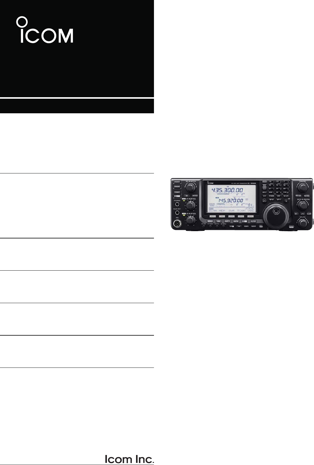
SUPPLIED ACCESSORIES
The transceiver comes with the following accessories.
Qty.
q Hand microphone ............................................ 1
w DC power cable* ............................................. 1
e Spare fuse (ATC 5 A) ...................................... 1
r Spare fuse (ATC 30 A) .................................... 2
tACC cable.........................................................1
y6.3 (d) mm plug................................................. 1
uDouble-sided tape............................................. 1
q
e
y
t
w
r
u
w
For European versions
(see p. 27 for installation details)
*Differs depending on the version.
FCC INFORMATION
s&/2#,!33"5.).4%.4)/.!,2!$)!4/23
This equipment has been tested and found to comply
with the limits for a Class B digital device, pursuant to
part 15 of the FCC Rules. These limits are designed
to provide reasonable protection against harmful
interference in a residential installation. This equip-
ment generates, uses and can radiate radio frequency
energy and, if not installed and used in accordance
with the instructions, may cause harmful interference
to radio communications. However, there is no guar-
antee that interference will not occur in a particular
installation. If this equipment does cause harmful
interference to radio or television reception, which can
be determined by turning the equipment off and on,
the user is encouraged to try to correct the interfer-
ence by one or more of the following measures:
s2EORIENTORRELOCATETHERECEIVINGANTENNA
s)NCREASETHESEPARATIONBETWEENTHEEQUIPMENT
and receiver.
s#ONNECTTHEEQUIPMENTINTOANOUTLETONA
circuit different from that to which the receiver is
connected.
s#ONSULTTHEDEALERORANEXPERIENCEDRADIO46
technician for help.

PRECAUTIONS
RDANGER HIGH RF VOLTAGE! NEVER
attach an antenna or internal antenna connector
during transmission. This may result in an electrical
shock or burn.
R WARNING! NEVER
operate the transceiver
with a headset or other audio accessories at high
volume levels. Hearing experts advise against continu-
ous high volume operation. If you experience a ringing
in your ears, reduce the volume or discontinue use.
R WARNING! NEVER operate or touch the
transceiver with wet hands. This may result in an
electric shock or damage to the transceiver.
R WARNING! NEVER apply AC power to the
[DC13.8V] socket on the transceiver rear panel. This
could cause a fire or damage the transceiver.
R WARNING! NEVER cut the DC power cable
between the DC plug and fuse holder. If an incorrect
connection is made after cutting, the transceiver may
be damaged.
R WARNING! NEVER apply more than 16 V
DC to the [DC13.8V] socket on the transceiver rear
panel, or use reverse polarity. This could cause a fire
or damage the transceiver.
R WARNING!
NEVER
let metal, wire or other
objects protrude into the transceiver or into connectors
on the rear panel. This may result in an electric shock.
R WARNING! Immediately turn OFF the trans-
ceiver power and remove the power cable if it emits
an abnormal odor, sound or smoke. Contact your
Icom dealer or distributor for advice.
R WARNING! NEVER put the transceiver in
any unstable place (such as on a slanted surface or
vibrated place). This may cause injury and/or damage
to the transceiver.
CAUTION: NEVER change the internal settings of
the transceiver. This may reduce transceiver perfor-
mance and/or damage to the transceiver.
In particular, incorrect settings for transmitter circuits,
such as output power, idling current, etc., might
damage the expensive final devices.
The transceiver warranty does not cover any prob-
lems caused by unauthorized internal adjustment.
CAUTION: NEVER block any cooling vents on
the top, rear, sides or bottom of the transceiver.
CAUTION: NEVER expose the transceiver to
rain, snow or any liquids.
CAUTION:
NEVER
install the transceiver in a
place without adequate ventilation. Heat dissipation
may be reduced, and the transceiver may be damaged.
DO NOT use harsh solvents such as benzine or
alcohol when cleaning, as they will damage the trans-
ceiver surfaces.
DO NOT push the PTT switch when you don’t actu-
ally desire to transmit.
DO NOT use or place the transceiver in areas with
temperatures below ±0°C (+32°F) or above +50°C
(+122°F).
DO NOT place the transceiver in excessively dusty
environments or in direct sunlight.
DO NOT place the transceiver against walls or
putting anything on top of the transceiver. This may
overheat the transceiver.
Always place unit in a secure place to avoid inadver-
tent use by children.
"% #!2%&5, If you use a linear amplifier, set
the transceiver’s RF output power to less than the
linear amplifier’s maximum input level, otherwise, the
linear amplifier will be damaged.
"% #!2%&5, The transceiver will become hot
when operating the transceiver continuously for long
periods of time.
USE only the specified microphone. Other manufac-
turers’ microphones have different pin assignments,
and connection to the IC-9100 may damage the
transceiver or microphone.
During maritime mobile operation, keep the trans-
ceiver and microphone as far away as possible from
the magnetic navigation compass to prevent errone-
ous indications.
Turn OFF the transceiver’s power and/or disconnect
the DC power cable when you will not use the trans-
ceiver for long period of time.
For U.S.A. only
CAUTION: Changes or modifications to this device,
not expressly approved by Icom Inc., could void your
authority to operate this device under FCC regula-
tions.
Icom, Icom Inc. and the Icom logo are registered trademarks of
Icom Incorporated (Japan) in Japan, the United States, the United
Kingdom, Germany, France, Spain, Russia and/or other countries.
Microsoft, Windows and Windows Vista are registered trademarks
of Microsoft Corporation in the United States and/or other countries.
All other products or brands are registered trademarks or trade-
marks of their respective holders.
ii
iii
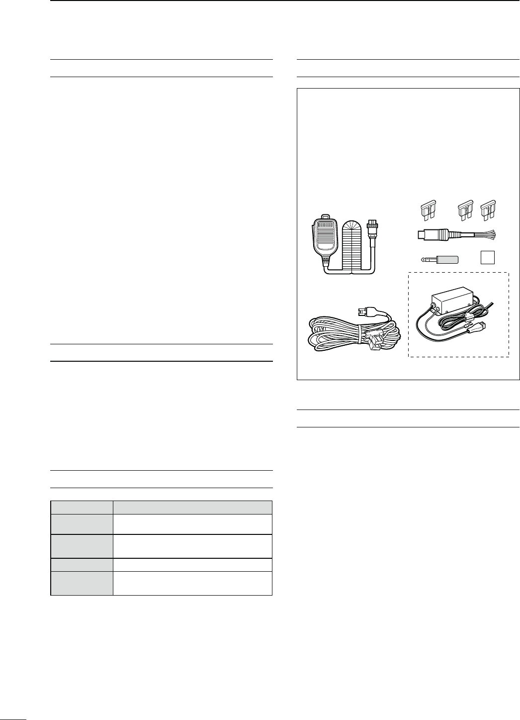
D About the D-STAR system
In the original D-STAR (Digital Smart Technologies for
Amateur Radio) plan, JARL envisioned a system of
repeaters grouped together into Zones. A zone would
be a group of up to 4 repeaters, linked by 10 GHz
“backbone” microwave Link repeaters. Each individual
repeater would be call an Area repeater, and would
be the Access repeater to begin communications.
Calls could be made to other Area repeaters within
the Zone, using the backbone Link repeater system.
One of the repeaters in the Zone would have an In-
ternet connection, and so in addition to being an Area
repeater, it also became the Zone Gateway repeater.
The Internet gateway provided a way to communicate
to other Zones, giving access to the Area repeaters
within them, and eventually to the entire world.
Call signs are the heart of D-STAR operation. Four call
signs are used:
s-9 4HISISYOUROWNCALLSIGN9OUENTERITONCEAND
then basically leave it set, with only a few ex-
ceptions.
s52 4HISISYOUR$ESTINATIONCALLSIGNTHATOFTHEAC-
tual ham or repeater you wish to contact. CQC-
QCQ can also be used to make a general call.
s2 4HISISTHE!REA!CCESSREPEATERCALLSIGNTHE
one you enter to begin your D-STAR repeater
communication.
s2 4HIS IS THE ,INK'ATEWAY REPEATER CALL SIGN
the repeater and Internet connection you go
through when you want contact a ham, or an-
other repeater, anywhere else in the world.
Call sign routing, one of the main features of D-STAR,
allows hams to contact other hams, or other repeat-
ers using just the ham’s or repeater’s call sign. The
D-STAR system will automatically route your signal to
the desired ham or repeater. Call sign capture allows
hams using an Icom radio to “capture” a call sign and
automatically program their radio for a reply.
Like other communication modes, you can operate
simplex D-STAR with other hams, for direct commu-
nication.
See pages 85 to 120 for the D-STAR operation de-
tails.
NOTE: The optional UT-121 is required for the D-
STAR operation with the IC-9100.
s$34!2SYSTEMOUTLINE
Station A
Station C Station D
Repeater A
Repeater D
440 MHz
440 MHz
Repeater C
10 GHz
Zone
Zone
Area
Station B
Repeater B
10 GHz
440 MHz
440 MHz
Internet
Internet
D-STAR INTRODUCTION
iv
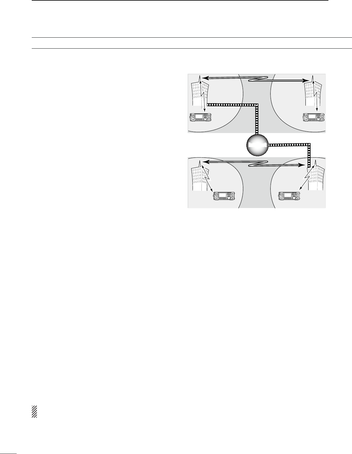
Area 1
Zone A
Repeater 1
Area 2
Repeater 2
Area 3
Repeater 3
Area 4
Repeater 4
Zone B
Area 7
Repeater 6
Area 6
Repeater 7
Area 8
Repeater 8
Area 5
Repeater 5
InternetInternet
(Gateway)
(Gateway)
Area:
The Area is the communication range
that is covered by a single repeater.
The repeater is called an area, or
access repeater in the D-STAR system.
Zone:
The Zone is composed of several areas, that are linked
by a 10 GHz microwave link.
Areas 1 to 4 and 5 to 8 make up a zone in the example
above.
Link repeater:
The microwave (10 GHz) link repeater
provides linking with another repeater
site (Area) for zone construction.
Gateway repeater:
Gateway repeaters provide communications between
different zones via the internet.
Repeater 3 and 6 are gateway repeaters at the
example above.
D$34!2SYSTEMDESCRIPTION

v
TABLE OF CONTENTS
FOREWORD .............................................................. I
IMPORTANT............................................................... I
EXPLICIT DEFINITIONS............................................ I
SUPPLIED ACCESSORIES....................................... I
FCC INFORMATION .................................................. I
PRECAUTIONS......................................................... II
D-STAR INTRODUCTION........................................ III
D About the D-STAR system ................................iii
D D-STAR system description ..............................iv
4!",%/&#/.4%.43 ............................................ v
1 PANEL DESCRIPTION................................... 1–21
N Front panel ........................................................ 1
N Rear panel....................................................... 10
D ACC socket information .............................. 13
D DATA2 socket information ........................... 14
N LCD display..................................................... 15
N Function display .............................................. 19
D M1 (Menu 1) display.................................... 19
D M2 (Menu 2) display.................................... 19
D M3 (Menu 3) display.................................... 19
D D1 display ................................................... 19
D D2 display ................................................... 19
D Function keys on M1 (Menu 1) display ....... 20
D Function keys on M2 (Menu 2) display ....... 20
D Function keys on M3 (Menu 3) display ....... 21
D Function keys on D1 display ....................... 21
D Function keys on D2 display ....................... 21
2 INSTALLATION AND CONNECTIONS........ 22–30
N Selecting a location......................................... 22
N Grounding ....................................................... 22
N Electronic keyer and microphone connections 22
N Antenna connection ........................................ 23
N Required connections ..................................... 24
DRear panel .................................................. 24
N Advanced connections.................................... 25
DFront panel.................................................. 25
DRear panel .................................................. 25
N External keypad connections .......................... 26
N Optional and the external units connections ... 26
N Power supply connections............................... 27
N Connecting a DC power supply....................... 27
D Connecting the PS-126
$#0/7%23500,9 ................................. 27
D Connecting a non-Icom
$#0/7%23500,9 ................................. 27
N Linear amplifier connections ........................... 28
DConnecting the IC-PW1/PW1EURO........... 28
DConnecting a non-Icom linear amplifier ...... 29
N External antenna tuner connection ................. 29
DConnecting the AH-4 .................................. 29
N Microphone connector information.................. 30
N Microphones.................................................... 30
DHM-36......................................................... 30
D SM-50 (Option) ........................................... 30
3"!3)#/0%2!4)/...................................... 31–46
N Before first applying power.............................. 31
N Turning ON (Partial resetting).......................... 31
N MAIN and SUB Bands..................................... 32
DMAIN/SUB Band selection.......................... 32
DSUB Band display....................................... 32
DSUB Band setting mode operation ............. 33
DThe SUB Dial function................................. 33
N VFO description............................................... 34
D Selecting the VFO A/B ............................... 34
D VFO equalization........................................ 34
N Selecting VFO/memory mode ......................... 34
N Selecting a frequency band............................. 35
DUsing the band stacking registers............... 35
N Frequency setting............................................ 37
DTuning with [MAIN DIAL]............................. 37
DDirect frequency entry with the keypad....... 37
DQuick tuning function .................................. 38
DSelecting “kHz” step.................................... 38
DSelecting 1 Hz step..................................... 39
DAuto tuning step function ............................ 39
D
1⁄4 tuning step function............................... 39
D About the 5 MHz frequency band operation
(only USA version)...................................... 40
DBand edge warning beep............................ 41
DProgramming the user band edge .............. 42
N Operating mode selection ............................... 43
N Squelch and receive (RF) sensitivity............... 44
N Volume setting................................................. 45
N Voice synthesizer operation............................. 45
N Meter Display selection ................................... 45
N Basic transmit operation.................................. 46
DTransmitting................................................. 46
DMicrophone gain adjustment....................... 46
4 RECEIVE AND TRANSMIT .......................... 47–68
N Operating SSB ................................................ 47
N Operating CW ................................................. 48
D About the CW reverse mode....................... 49
D About CW pitch control ............................... 49
D About keying speed..................................... 49
D
CW sidetone function.................................. 49

vi
1
2
3
4
5
6
7
8
9
10
11
12
13
14
15
16
17
18
19
20
21
N Electronic keyer functions ............................... 50
D Memory keyer menu construction............... 50
D Memory keyer send menu........................... 51
D Editing a memory keyer .............................. 52
D Contest number Set mode.......................... 53
D Keyer Set mode .......................................... 54
N/PERATING2449&3+.................................... 56
N2449FUNCTIONS................................................ 57
D#ONSTRUCTIONOF2449MENU ....................... 57
D!BOUT2449REVERSEMODE ......................... 58
D Twin Peak Filter........................................... 58
D2449DECODER............................................. 59
D24493ETMODE .......................................... 60
N Operating AM/FM............................................ 61
N Tone squelch operation ................................... 62
N DTCS operation .............................................. 63
N Tone scan/DTCS code scan operation............ 64
Repeater operation.......................................... 65
D Repeater access tone frequency setting..... 65
D One-touch repeater function ....................... 66
D Transmit frequency monitor check............... 66
D Setting the Auto Repeater ranges
(U.S.A. and Korea versions only) ................ 67
D Turning ON the Auto Repeater function
(U.S.A. and Korea versions only) ................ 68
D Storing a non standard repeater ................ 68
5 FUNCTIONS FOR RECEIVE........................ 69–77
N AFC operation................................................. 69
N RIT function..................................................... 69
D RIT monitor function.................................... 69
N Simple band scope.......................................... 70
N Preamplifier..................................................... 71
N Attenuator........................................................ 71
N AGC function................................................... 72
D AGC speed selection .................................. 72
D Setting the AGC time constant.................... 72
N IF filter selection.............................................. 73
D IF filter selection.......................................... 73
DFilter passband width setting ...................... 73
D 1st IF filter selection.................................... 74
DIF (DSP) filter shape ................................... 74
N Twin PBT operation ......................................... 75
N Noise Blanker.................................................. 76
D NB Set mode............................................... 76
N Meter peak hold function................................. 76
N
Noise Reduction.............................................. 77
N Dial Lock function............................................ 77
N Notch function ................................................. 77
6 FUNCTIONS FOR TRANSMIT ..................... 78–84
N VOX function.................................................... 78
D Using the VOX function ............................... 78
D Adjusting the VOX function.......................... 78
N Break-in function ............................................. 79
D Semi Break-in operation ............................. 79
D Full Break-in operation................................ 79
N Speech compressor ........................................ 80
N
Transmit filter width selection ............................80
N∂TX function ................................................... 81
D∂TX Monitor function .................................. 81
N Monitor function............................................... 81
N Split frequency operation ................................ 82
N Quick Split function ......................................... 83
D Split frequency offset setting....................... 83
D Split Lock function....................................... 83
N Measuring SWR.............................................. 84
D Spot measurement...................................... 84
D Plot measurement....................................... 84
7 DV MODE PROGRAMMING ........................ 85–92
N Call sign programming .................................... 85
Dh-9v9OUROWNCALLSIGNPROGRAMMING ...... 85
D “UR” (Destination call sign) programming... 86
D“R1” (Access/Area repeater call sign) and
“R2” (Link/Gateway repeater call sign)
programming............................................... 87
N Repeater list.................................................... 88
D Repeater list contents ................................. 88
N
Repeater list programming..................................89
N Editing a repeater list ...................................... 91
N
Clearing a repeater list........................................92
8 DV MODE OPERATION ............................. 93–120
N Digital mode operation .................................... 93
N Call sign setting............................................... 93
N Receiving a D-STAR repeater ......................... 94
N Received call signs.......................................... 95
D Desired call record display.......................... 95
D One-touch reply using the call record ......... 96
N Copying the call sign ....................................... 97
D Copying the call sign memory contents ...... 97
DCopying the call record contents
into call sign memory.................................. 98
N DR (D-STAR Repeater) mode operation......... 99
D Communication Form.................................. 99
D Access repeater scan ............................... 100
N Calling CQ..................................................... 101
D Storing the set data................................... 102

vii
TABLE OF CONTENTS
N Calling a specific station................................ 103
D Confirming the setting............................... 105
DSettings for “UR” and “R2,” depending on the
communication form.................................. 105
N Simplex operation using the VFO.................. 106
DMaking a simplex CQ call or a call to
an individual station .................................. 106
N Repeater operation using the VFO................ 107
DMaking a CQ call or a call to an individual
station through your local area (access)
repeater (Local Area call).......................... 107
DMaking a CQ call or a call to an individual
station through a link repeater in the same
zone (Zone call) ........................................ 108
DMaking a CQ call or a call to an individual
station through gateway repeaters
(Gateway call) ........................................... 109
DSettings for “UR” and “R2,” depending on the
communication form.................................. 110
N Message operation........................................ 111
D TX message programming........................ 111
D Message Transmission.............................. 112
D RX message display ................................. 112
N DV automatic detection ................................. 113
N Automatic reply function................................ 113
N Digital squelch functions ............................... 114
N EMR communication..................................... 115
D Adjusting the EMR AF level ...................... 115
N Break-in communication................................ 116
N Low-speed data communication.................... 117
D Connection................................................ 117
DLow-speed data communication application
setting ....................................................... 117
DLow-speed data communication operation117
N Packet loss indication.................................... 117
N DV Set mode description............................... 118
D DV Set mode settings ............................... 118
9 GPS/GPS-A OPERATION ........................ 121–137
N GPS operation............................................... 121
D GPS screen construction .......................... 121
D GPS data communication ......................... 122
D Sentence formatter setting........................ 122
D Position display ......................................... 123
D Saving your own or received position data 124
D Display the Grid Locator information......... 124
D GPS automatic transmission..................... 124
D GPS message programming..................... 125
D Received GPS message display............... 126
N GPS memory operation................................. 127
D Add a GPS memory.................................. 127
D Edit a GPS memory.................................. 129
D GPS alarm setting..................................... 130
D GPS memory clearing............................... 131
N GPS Set mode .............................................. 132
N GPS-A operation........................................... 137
D GPS-A function ......................................... 137
D
GPS-A code details................................... 137
10 MEMORY OPERATION............................ 138–144
N General description....................................... 138
D Memory channel contents......................... 138
N Memory channel selection ............................ 139
D Selection in the VFO mode ....................... 139
D Selection in the Memory mode ................. 139
NCall channel selection ................................... 139
N Memory channel programming ..................... 140
D Programming in the VFO mode ................ 140
D Programming in the Memory mode........... 140
NCall channel programming ............................ 141
N Memory clearing ........................................... 141
N Memory contents copying ............................. 142
D Copying in the VFO mode......................... 142
D Copying in the Memory mode................... 142
NMemory name programming......................... 143
NMemo pad function........................................ 144
D
Writing the displayed data into memo pads
. 144
D Calling up the memo pads ........................ 144
11 SCANS ..................................................... 145–152
N Scan types .................................................... 145
N Preparation.................................................... 146
N Voice Squelch Control function ..................... 146
N Scan set mode .............................................. 147
NScan edges programming............................. 148
NProgrammed scan/Fine programmed scan
(VFO mode) .................................................. 149
D About the Fine programmed scan............. 149
N Memory scan (Memory mode)...................... 150
D Memory scan ............................................ 150
D Mode Select scan ..................................... 150
D
Setting/Cancelling Select Memory channels
. 151
D Select Memory scan ................................. 151
N∂F scan and Fine ∂F scan ........................... 152
D About the Fine ∂F scan ............................ 152

viii
1
2
3
4
5
6
7
8
9
10
11
12
13
14
15
16
17
18
19
20
21
12 SATELLITE OPERATION......................... 153–157
N Satellite communications outline................... 153
N Satellite notes................................................ 153
N Selecting the satellite mode .......................... 153
DTransferring the VFO frequencies to the
satellite VFO.............................................. 153
N Setting the satellite VFO................................ 154
N Tracking selection.......................................... 154
D Normal tracking......................................... 154
D Reverse tracking ....................................... 154
N Satellite memory ........................................... 155
D Satellite memory selection........................ 155
D Satellite memory programming................. 155
N Preparation.................................................... 156
N Satellite operation ......................................... 157
13 ANTENNA TUNER OPERATION ............. 158–160
N Antenna connection and selection ................ 158
N Antenna tuner operation................................ 159
D Tuner operation ......................................... 159
D Manual tuning ........................................... 159
N Optional external tuner operation.................. 160
14 SET MODE ............................................... 161–172
N Set mode description .................................... 161
D The Set mode settings .............................. 161
N Tone control Set mode description................ 169
D The Tone control Set mode settings.......... 169
15 DATA COMMUNICATION......................... 171–173
N Connections .................................................. 171
D When connecting to [DATA2]..................... 171
D When connecting to [ACC]........................ 171
D When connecting to [MIC]......................... 171
N Packet (AFSK) operation............................... 172
D Frequency display during AFSK operation 172
N Data transmission speed............................... 173
N Adjusting the TNC output level...................... 173
D Using a level meter or synchroscope........ 173
D Not using a measuring device................... 173
16 OPTION INSTALLATION ......................... 174–176
N Opening the transceiver’s case ..................... 174
N UX-9100 1200 MHz BAND UNIT installation ...... 175
N FL-430/FL-431 1ST IF FILTER installation........ 176
N UT-121 DIGITAL UNIT installation ..................... 176
17 MAINTENANCE ....................................... 177–182
N Troubleshooting ............................................. 177
DTransceiver power..................................... 177
DTransmit and receive................................. 177
DScanning................................................... 178
DDisplay...................................................... 178
N Frequency calibration (approximate)............. 179
N Main dial tuning tension adjustment.............. 179
N Fuse replacement ......................................... 180
DDC power cable fuse replacement............ 180
DCircuitry fuse replacement........................ 180
N Resetting the CPU ........................................ 181
DPartial reset............................................... 181
DAll reset..................................................... 181
N Data cloning .................................................. 182
DCloning between transceivers.................... 182
DCloning using a personal computer ........... 182
18 CONTROL COMMAND ............................ 183–196
N Remote jack (CI-V) information..................... 183
DCI-V connection example.......................... 183
DData format............................................... 183
DCommand table ........................................ 184
DData content description........................... 190
19 SPECIFICATIONS .................................... 197–198
N General.............................................................. 197
N Transmitter..................................................... 197
N Receiver........................................................ 198
N Antenna tuner................................................ 198
20 OPTIONS.................................................. 199–200
21 CE............................................................. 201–202
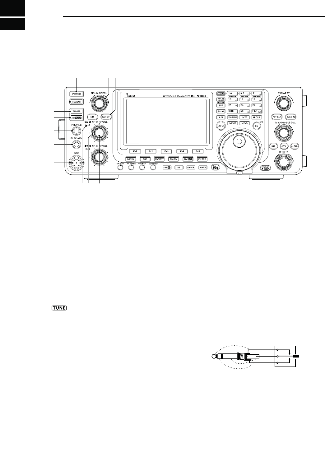
1
1
PANEL DESCRIPTION
qPOWER SWITCH [POWER] (p. 31)
±Push to turn ON the transceiver power.
s&IRSTCONlRMTHE$#POWERSOURCEISTURNED/.
±Hold down for 1 second to turn OFF the power.
wTRANSMIT SWITCH [TRANSMIT] (p. 46)
Push to select transmit or receive.
s7HILETRANSMITTINGTHE-!).OR35""ANDS4828IN-
dicator (i or !5) lights red.
s7HILERECEIVINGORWHENTHESQUELCHOPENSTHEINDICA-
tor lights green.
eANTENNA TUNER SWITCH [TUNER] (p. 159)
&REQUENCYBAND(&-(Z
± Push to turn the internal antenna tuner ON or
OFF (bypass).
sh ” appears when the tuner is turned ON.
s4HEINTERNALANTENNATUNERSETTINGSCANBEMEMO-
rized in each frequency band.
±Hold down for 1 second to manually start the an-
tenna tuner.
s)FTHETUNERCANNOTTUNETHEANTENNAWITHINSEC-
onds, the tuning circuit is automatically bypassed.
r
!.4%..!s-%4%237)4#(;!.4s-%4%2=
!.4%..!37)4#(/PERATION
(p. 158)
&REQUENCYBAND(&-(Z
± Push to select either the ANT1 or ANT2 connec-
tor.
-%4%237)4#(/PERATION
(p. 45)
&REQUENCYBAND!,,
± Hold down for 1 second to toggle the transmit
meter function between ALC, COMP and SWR.
tHEADPHONE JACK [PHONES]
Plug in standard stereo headphones (impedance: 8
to 16 ø).
s/UTPUTPOWER-ORETHANM7WITHANø load.
s7HENHEADPHONESARECONNECTEDTHEINTERNALSPEAKER
and any external speaker, are disabled.
s4HE-!).AND35""ANDAUDIOCANBEMIXEDORSEPA-
rated when using stereo headphones, depending on
the
“Phone Separate” option in the Set mode
. (p. 160)
yELECTRONIC KEYER JACK [ELEC-KEY]
Plug in a bug or paddle type key to use the internal
electronic keyer for CW operation. (p. 22)
s3ETTHEKEYERTYPETO%,%#+%9"5'+%9OR3TRAIGHT
key in the “Keyer Type” item of the Keyer Set mode.
s!STRAIGHTKEYJACKISLOCATEDONTHEREARPANEL3EE
;+%9=ONPAGE
s9OU CAN REVERSE THE KEYER PADDLE POLARITY DOT AND
dash) in
the “Paddle Polarity” item
of
the Keyer Set mode.
(p. 55)
s&OURKEYERMEMORYCHANNELSAREAVAILABLEFORYOURCON-
venience. (p. 51)
ot
o
a
uMICROPHONE CONNECTOR [MIC]
Plug in the supplied or an optional microphone.
s3EEPAGEFORAPPROPRIATEMICROPHONES
s3EEPAGEFORMICROPHONECONNECTORINFORMATION
i-!)."!.$4828).$)#!4/2
± Lights green when the squelch opens, or a signal
ISRECEIVEDONTHE-!)."ANDLIGHTSREDDURING
transmit.
± Blinks green when an off-frequency signal is re-
ceived, depending on the “FM/DV Center Error”
option in the Set mode. (p. 162)
N&RONTPANEL
t
i !0
y
q
e
r
u
o
!2!1
w
2
1
PANEL DESCRIPTION
1
o-!)."!.$2&'!).#/.42/,
SQUELCH CONTROL [RF/SQL]
OUTERCONTROLP
Rotate to adjust the RF gain and squelch threshold
level for the MAIN Band.
The squelch removes noise output to the speaker
when no signal is received. (closed condition)
s4HESQUELCHISPARTICULARLYEFFECTIVEFOR!-AND&-BUT
also works in other modes.
s4HETOOCLOCKPOSITIONISRECOMMENDEDfor the
most effective use of the [RF/SQL] control.
s[RF/SQL] operates as only an RF gain control in SSB,
#7AND2449Squelch is fixed open), or a squelch
control in AM, FM and DV (RF gain is fixed at maxi-
mum sensitivity), when “Auto” is selected as the
“RF/
SQL Control” item option in
the Set mode. (p. 162)
s7HENUSEDASAN2&GAINSQUELCHCONTROL
Maximum
RF gain
S-meter
squelch
Noise squelch (FM/DV modes)
Squelch is
open.
RF gain
adjustable
range
Recommended level
s7HENUSEDASAN2&GAINCONTROL
3QUELCHISlXEDOPEN33"#7AND2449ONLY
Minimum RF gain
Adjustable
range
Maximum
RF gain
While rotating the RF gain control, a faint noise may
be heard. This comes from the DSP unit and does
not indicate an equipment malfunction.
s7HENUSEDASASQUELCHCONTROL
(RF gain is fixed at maximum.)
Squelch is
open.
S-meter
squelch
S-meter squelch
threshold
Noise squelch
threshold
(FM mode)
Shallow Deep
Noise squelch (FM/DV modes)
!0-!)."!.$!&#/.42/,;!&=
INNERCONTROLP
Rotate to adjust audio output level to the speaker or
headphones on the MAIN Band.
n rea
e
De rea e
!1 NOTCH SWITCH [NOTCH] (p. 77)
-ODE!UTONOTCH 33"!-&-
-ANUALNOTCH33"#72449!-
±In the SSB and AM modes, push to toggle the
notch function between auto, manual and OFF.
s%ITHERTHE!UTOOR-ANUALNOTCHFUNCTIONCANBE
turned OFF in
the “[NOTCH] SW” item
of the Set
mode. (p. 36)
±In the FM mode, push to turn the Auto Notch
function ON or OFF.
±In the #7OR2449 mode, push to turn the Man-
ual Notch function ON or OFF.
sh-.&vAPPEARSWHENTHE-ANUAL.OTCHFUNCTIONIS
ON.
sh!.&vAPPEARSWHENTHE!UTO.OTCHFUNCTIONIS/.
s.OINDICATORAPPEARSWHENTHENOTCHlLTERIS/&&
± Hold down for 1 second to switch the manual
filter characteristics from wide, mid and narrow,
when the Manual Notch function is selected.
What is the notch filter?
The notch filter is a narrow filter that eliminates un-
wanted CW or AM carrier tones, while preserving
the desired voice signal. The DSP circuit automati-
cally adjusts the notch frequency to effectively elim-
inate unwanted tones.
!2 MANUAL NOTCH FILTER CONTROL [NOTCH]
OUTERCONTROLP
Rotate to adjust the notch frequency to reject an
interfering signal while the manual function is ON.
s.OTCHlLTERCENTERFREQUENCY
33"2449 n(ZTO(Z
CW : CW pitch freq. –2540 Hz to
CW pitch freq. +2540 Hz
AM : –5060 Hz to +5100 Hz
Higher frequency
Lower frequency
The optional UX-9100 is required for 1200 MHz frequency
band operation.
The optional UT-121 is required for DV mode operation.
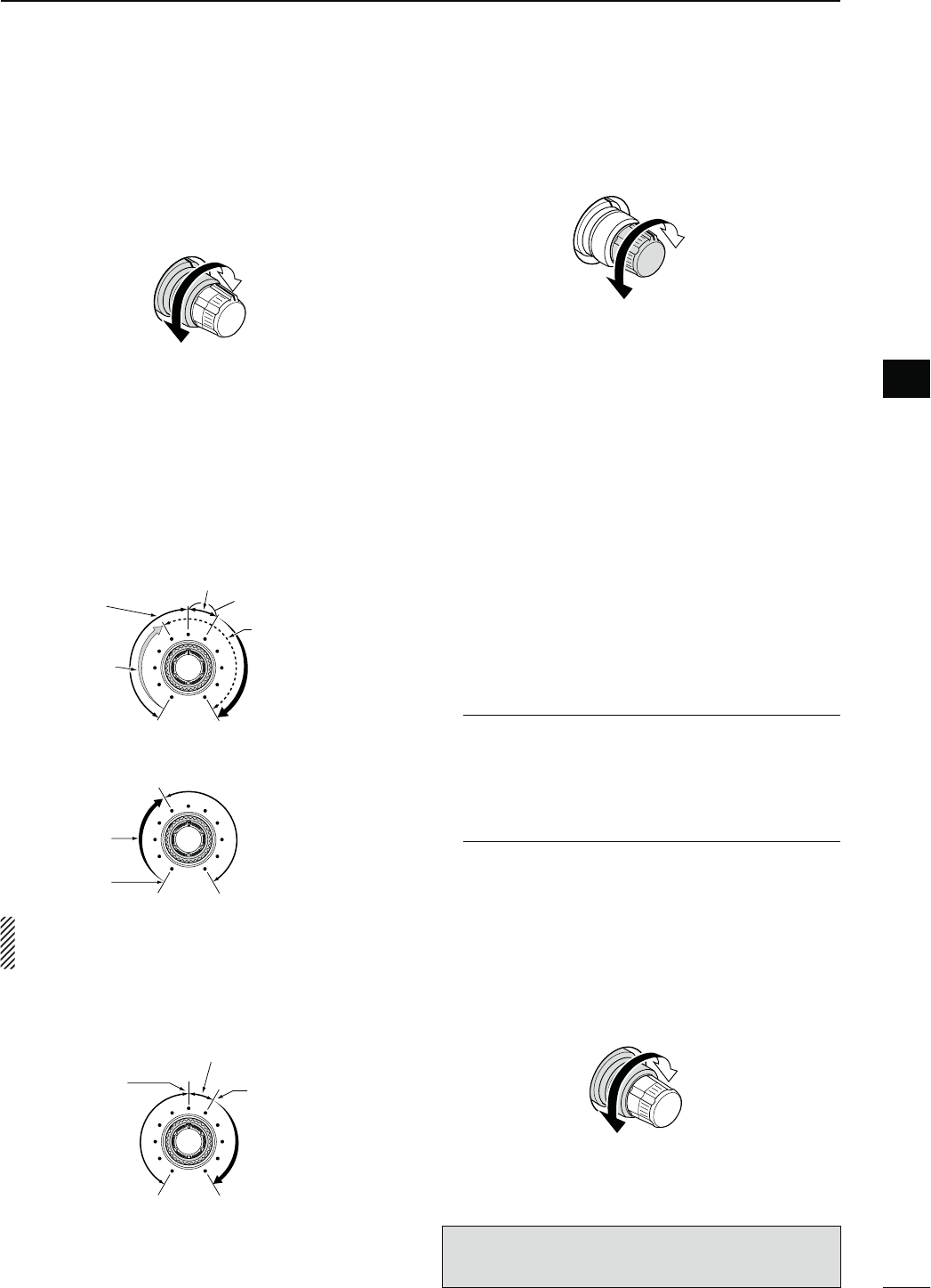
!3 MENU SWITCH [MENU] (p. 19)
± Push to change the set of functions assigned to
switches ([F-1] to [F-5]).
s4OGGLES THE FUNCTION DISPLAY MENU BETWEEN -
(Menu 1), M2 (Menu 2), M3 (Menu 3), D1 and D2.
± Hold down for 1 second to enter the Set mode.
Push to return to the previous screen display.
!4 NOISE REDUCTION LEVEL CONTROL [NR]
INNERCONTROLP
Rotate to adjust the DSP noise reduction level
when the noise reduction function is in use. Set for
maximum readability.
s4OUSETHISCONTROLlRSTPUSH[NR] (!5).
Increases
Decreases
!5 NOISE REDUCTION SWITCH [NR] (p. 77)
Push to turn DSP noise reduction ON or OFF.
sh.2vAPPEARSWHENNOISEREDUCTIONIS/.
!635""!.$4828).$)#!4/2
Lights green when the squelch opens, or a signal is
RECEIVEDONTHE35""ANDLIGHTSREDDURINGTRANS-
mit in the satellite mode.
± Blinks green when an off-frequency signal is re-
ceived, depending on the “FM/DV Center Error”
option in the Set mode. (p. 162)
!735""!.$2&'!).#/.42/,
SQUELCH CONTROL [RF/SQL]
OUTERCONTROLP
Rotate to adjust the RF gain and squelch threshold
level on the SUB Band.
The squelch stops noise output to the speaker
when no signal is received. (closed condition)
See o on page 2 for details.
!8
35""!.$!&#/.42/,;!&=INNERCONTROLP
Rotate to adjust audio output level to the speaker or
headphones on the SUB Band.
!9 MIC GAIN CONTROL [MIC GAIN] (p. 46)
Rotate to adjust the microphone gain.
s4HETRANSMITAUDIOTONEINTHE33"!-AND&-MODESCAN
be independently adjusted in the tone control Set mode.
(p. 169)
How to set the microphone gain.
Set the meter function to ALC. (p. 45) While speak-
ing at normal voice level, adjust the [MIC GAIN]
control so that in the SSB or AM modes, the ALC
meter swings within the ALC range.
Recommended level for
Icom microphones
IncreasesDecreases
@0 RF POWER CONTROL [RF POWER] (p. 46)
Rotate to continuously vary the RF output power.
IncreasesDecreases
&REQUENCYBAND 2&OUTPUTPOWERRANGE
HF/50 MHz 2 to 100 W (AM: 2 to 30 W)
144 MHz 2 to 100 W
430 MHz 2 to 75 W
1200 MHz 1 to 10 W
@1 CW PITCH CONTROL [CW PITCH]
OUTERCONTROLP
-ODE#7
Rotate to shift the received CW audio pitch and the
CW sidetone pitch without changing the operating
frequency.
s4HEPITCHCANBEADJUSTEDFROMTO(ZINAP-
proximatly 5 Hz steps.
Higher pitchLower pitch
N Front panel (continued)
3
1PANEL DESCRIPTION
!6 !8!7
!4
!5
!9 @0 @1 @2 @3 @4 @5 @6 @7 @8
!38

@2 ELECTRONIC CW KEYER SPEED CONTROL
[KEY SPEED] (p. 49)
-ODE#7
Rotate to adjust the keying speed of the internal
electronic CW keyer to between 6 wpm (minimum)
and 48 wpm (maximum).
FastSlow
@302%!-0s!44%.5!4/237)4#(;0!-0s!44=
PREAMP SWITCH/PERATION(p. 71)
&REQUENCYBAND(&-(Z
± Push to select one of two receive RF preampli-
fiers, or to bypass them.
sh0!-0 ” is a wide dynamic range preamplifier. It is
most effective for the 1.8 to 21 MHz bands.
sh0!-0 ” is a high-gain preamplifier. It is most ef-
fective for the 24 to 50 MHz bands.
s.OINDICATORAPPEARSWHENTHEPREAMPLIlERSARENOT
selected.
&REQUENCYBAND-(Z
± Push to turn an optional AG-25, AG-35 or AG-
1200* pre-amplifier unit ON or OFF, if installed.
sh0!-0vAPPEARSWHENTHEPREAMPLIlERUNITIS/.
*AG-1200 has been discontinued, but it can be still be
used.
What is the preamplifier?
The preamplifier amplifies signals in the front end to
improve the S/N ratio and sensitivity. Select “P. AMP
” or “P. AMP ” when receiving weak signals.
!44%.5!4/237)4#(/PERATION(p. 71)
± Hold down for 1 second to turn ON the attenua-
tor.
sh!44vAPPEARSWHENTHEATTENUATORIS/.
± Push to turn OFF the attenuator.
sh!44vDISAPPEARS
What is the attenuator?
The attenuator prevents a desired signal from being
distorted when very strong signals are near it, or
when very strong electromagnetic fields, such as
from a broadcasting station, are near your location.
@4./)3%",!.+%237)4#(;."= (p. 76)
± Push to turn the noise blanker ON or OFF. The
noise blanker reduces pulse-type noise such as
that generated by vehicle ignition systems. The
noise blanker is not effective for non-pulse-type
noise.
sh."vAPPEARSWHENTHENOISEBLANKERIS/.
± Hold down for 1 second to display the “NB”
screen. Push to return to the previous screen
display.
@56/8"+).37)4#(;6/8"+).=
VOX SWITCH/PERATION(p. 78)
-ODE33"!-&-$6
± Push to turn the VOX function ON or OFF.
± Hold down for 1 second to display the “VOX”
screen. Push to return to the previous screen
display.
What is the VOX function?
The VOX function (voice operated transmission)
automatically starts transmission when you speak
INTOTHEMICROPHONETHENAUTOMATICALLYRETURNSTO
receive when you stop speaking.
"+).37)4#(/PERATION(p. 79)
-ODE#7
± Push to toggle the break-in operation between
semi break-in and full break-in, or to turn OFF
the break-in function.
± Hold down for 1 second to display the “BKIN”
screen (Break-in). Push to return to the previous
screen display.
What is the break-in function?
The break-in function automatically switches be-
tween transmit and receive with your CW keying.
Using Full break-in function (QSK), you can hear
the receive frequency in-between keying.
@6 MONITOR SWITCH [MONITOR] (p. 81)
± Push to turn the Monitor function ON or OFF to
listen to your own transmitted audio.
sh-/.)vAPPEARSWHENTHISFUNCTIONIS/.
s)N#7MODETHE#7SIDETONECANBEHEARDREGARD-
less of the [MONITOR] switch setting.
± Hold down for 1 second to display the “MONI”
screen (Monitor) to set the monitor level. Push to
return to the previous screen display.
@7#!,,s'0337)4#(;#!,,s'03=
CALL SWITCH/PERATION(p. 139)
Push to select the call channel.
GPS SWITCH/PERATION(p. 121)
Hold down for 1 second to display the “GPS” screen.
Push to return to the previous screen display.
@8 FUNCTION SWITCHES [F1]–[F5]
Push to select the function which is indicated on the
LCD display above each switch. (p. 19)
s4HEFUNCTIONSVARYDEPENDINGONTHESELECTEDMENU
and the operating mode.
4
1
PANEL DESCRIPTION
1
The optional UX-9100 is required for 1200 MHz frequency
band operation.
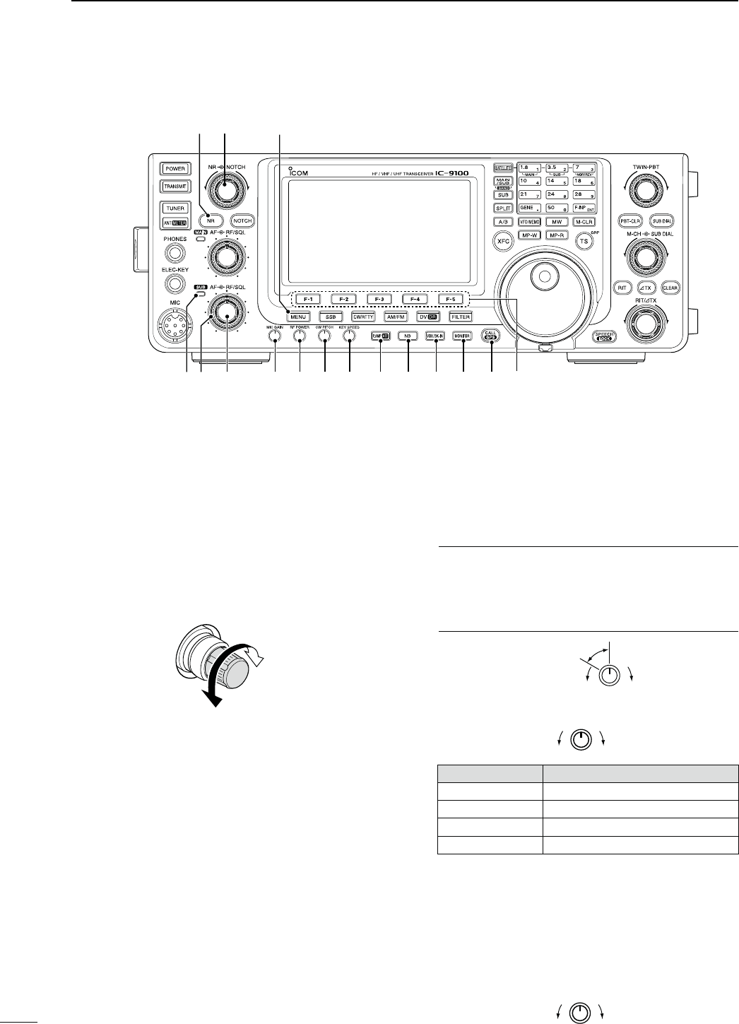
@9 MODE SWITCHES
Push to select your desired operating mode. (p. 43)
s4HEBUILTINSPEECHSYNTHESIZERANNOUNCESTHESELECTED
mode when the “SPEECH [MODE] SW” item is set to
“ON” in the Set mode. (p. 164)
;33"= (p. 47)
±
Push to alternately select the USB or LSB modes.
sh53"vORh,3"vAPPEARS
±
In the SSB mode,
hold down for 1 second to s
e-
lect the SSB data mode (USB-D, LSB-D).
shD” appears in addition to “USB” or “LSB.”
±
In the SSB data mode, push to return to the normal
SSB mode.
[CW/RTTY] (pp. 48, 56)
±0USH TO ALTERNATELY SELECT THE #7 OR 2449
modes.
sh#7vORh2449vAPPEARS
± Hold down for 1 second to switch between the
CW and CW-R (CW reverse) modes, in the CW
mode.
sh#72vAPPEARSWHENTHE#7REVERSEMODEIS
selected.
± Hold down for 1 second to switch between the
2449AND244922449REVERSEMODESIN
THE2449MODE
sh24492vAPPEARSWHENTHE2449REVERSEMODEIS
selected.
[AM/FM] (p. 61)
±
Push to alternately select the AM or FM modes.
sh!-vORh&-vAPPEARS
± Hold down for 1 second to select the AM or FM
data mode (AM-D/FM-D).
shD” appears in addition to “AM” or “FM.”
± In the data mode, push to return to the normal
AM or FM mode.
NOTE:
s)NTHE!-MODEYOUCANTRANSMITONONLYTHE
HF/50MHz frequency bands.
s4HE!-MODECANNOTBESELECTEDONTHE
MHz frequency band.
;$6s$2= (p. 85)
±Push to select the DV mode.
sh$6vBLINKS
±Hold down for 1 second to select the DR mode.
sh$6vh” and “r” appear.
±In the DR mode, push to cancel it.
sh” and “r” disappear.
#0 FILTER SWITCH [FILTER] (p. 73)
± Push to select one of three IF filter settings ( / /
).
s4HESELECTEDlLTERPASSBANDWIDTHANDSHIFTINGVALUE
are displayed for 2 seconds on the LCD display.
± Hold down for 1 second to display the “FIL”
screen (Filter) to set the filter passband width.
±
When the “FIL” screen is displayed, hold down for
1 second to return to the previous screen display.
#1
TRANSMIT FREQUENCY CHECK SWITCH [XFC]
± During split frequency or repeater operation, hold
down to listen to the transmit frequency. (p. 82)
s7HILE HOLDINGDOWNTHIS SWITCHTHE TRANSMITFRE-
quency can be changed with the main dial, keypad
or memo pad.
s7HEN THE SPLIT LOCK FUNCTION IS TURNED /. PUSH
[XFC] to cancel the dial lock function. (pp. 82, 162)
± When the RIT function is turned ON, hold
down to listen to the receive frequency. (RIT is
temporarily cancelled.) (p. 69)
± When the ∂TX function is turned ON, hold down
to listen to the transmit frequency (including ∂TX
frequency offset). (p. 81)
± In the simplex operation, hold down to listen to
the receive frequency.
s4HESQUELCHISCLOSEDANDTHEINTERFERENCEREJECT
function is temporary OFF while holding down this
switch.
± In the DV mode, the RX monitoring mode is se-
lected by holding down this switch. (p. 118)
N Front panel (continued)
5
1PANEL DESCRIPTION
@9 #0
#2#3#4#5 #6 #7#1

#26&/3%,%#437)4#(;!"= (pp. 32, 34)
±Push to select either VFO A or VFO B.
±
Hold down for 1 second to equalize the undis-
played VFO settings to that of the displayed VFO.
#3 SPLIT SWITCH [SPLIT] (p. 82)
± Push to turn the split function ON or OFF.
sh30,)4vAPPEARSWHENTHESPLITFUNCTIONIS/.
s4HE SPLIT FUNCTION IS NOT SELECTABLE ON THE 35"
Band.
± Hold down for 1 second to activate the quick split
function.
s4HETRANSMITFREQUENCYSHIFTSFROMTHERECEIVEFRE-
quency according to the “SPLIT Offset” option in the
Set mode. (p. 162)
s4HEQUICKSPLITFUNCTIONCANBETURNED/&&IN
the
“Quick SPLIT” item
of the Set mode. (p. 162)
#435"37)4#(;35"=
± Push to turn the SUB Band setting mode ON or
OFF. (p. 33)
sh” appears when the SUB Band setting mode is
ON.
± Hold down for 1 second to turn the SUB Band
display ON or OFF. (p. 32)
#5-!).35"s"!.$37)4#(;-!).35"s"!.$=
± Push to toggle between the MAIN Band and the
SUB Band. (p. 32)
± Hold down for 1 second several times to select
HF/50 MHz, 144 MHz, 430 MHz or 1200 MHz
frequency band as your operating band. (p. 35)
s4HEFREQUENCYBANDSELECTEDINEITHERTHE-!).OR
SUB Band, cannot be selected on the other Band.
#6 SATELLITE SWITCH [SATELLITE] (p. 153)
± Push to enter the satellite mode (receive on
MAIN Band, transmit on SUB Band).
sh ” appears.
s4HELASTOPERATEDFREQUENCIESDOWNLINKANDUPLINK
and tracking icon (“ ”/“ ”) appears.
± In the satellite mode, push to return to the previ-
ous screen display.
NOTE: In the DR mode, pushing [SATELLITE]
cancels DR, and then switches the transceiver to
the satellite mode.
If you want to operate in the DR mode after
exiting the satellite mode, you must hold down
;$6s$2=FORSECOND
± Hold down for 1 second to transfer the uplink and
downlink frequencies into the satellite VFO.
s4HESATELLITEMODEISAUTOMATICALLYSELECTEDAFTER
transferring.
sh ” appears.
s4HELASTOPERATEDTRACKINGICONh ”/“ ”)
appears.
s4OTOGGLETHETRACKINGOPERATIONBETWEENNORMALAND
reverse, push [NOR/REV] (7 3).
± In the satellite mode, hold down for 1 second to
return to normal operation using the displayed
frequencies.
#7"!.$+%93+%90!$
"!.$+%93/PERATION (pp. 35, 36)
When the HF/50 MHz frequency band is not se-
lected in both the MAIN or SUB Band, you can se-
lect the HF/50 MHz frequency band by just holding
down the band key for 1 second.
&REQUENCYBAND(&-(Z
± Push to select the operating band.
s;'%.%s=SELECTSTHEGENERALCOVERAGEBAND
± Pushing the same key two or three times calls
up other stacked frequencies in the frequency
band.
s)COMSTRIPLEBANDSTACKINGREGISTERMEMORIZESTHREE
frequencies in each frequency band.
&REQUENCYBAND-(Z
±0USHING;'%.%s=TWOORTHREETIMESCALLSUP
other stacked frequencies in the frequency
band, after selecting the 144 MHz, 430 MHz
or 1200 MHz frequency band by holding down
[BAND](MAIN/SUB) for 1 second.
± Hold down for 1 second to switch the operating
band to the HF/50 MHz frequency band.
s;'%.%s=SELECTSTHEGENERALCOVERAGEBAND
sPushing the same key two or three times calls up
other stacked frequencies in the frequency band.
+%90!$/PERATION (p. 37)
After pushing [F-INP ENT], push the keys on the
keypad to enter a frequency. After entering, push
[F-INP ENT] to set the frequency.
s%XAMPLE4OENTER-(Z
0USH;&).0%.4=;=;=;s=;=;=;=;&).0%.4=
NOTE: The frequency band, selected in either
the MAIN or SUB Band, cannot be selected on
the other Band.
While in the satellite mode, the keypad operation is
different than described above. See page 154 for
details.
6
1
PANEL DESCRIPTION
1
The optional UX-9100 is required for 1200 MHz frequency
band operation.
The optional UT-121 is required for DV mode operation.
#8 VFO/MEMORY SWITCH [VFO/MEMO]
± Push to switch between the VFO and memory
modes. (pp. 34, 139)
± Hold down for 1 second to copy the memory con-
tents to the displayed VFO on the MAIN Band.
(p. 142)
#9 MEMO PAD-WRITE SWITCH [MP-W] (p. 144)
Push to write the displayed data into a memo pad.
s4HEMOSTRECENTENTRIESREMAININTHEMEMOPADS
s4HEMEMOPADCAPACITYCAN BEEXTENDEDFROM TO
10 in
the “Memopad Numbers” item
of the Set mode.
(p. 164)
$0 MEMORY WRITE SWITCH [MW] (p. 140)
Hold down for 1 second to store VFO data into the
selected memory channel.
s4HISCANBEDONEINBOTHTHE6&/ANDMEMORYMODES
$1 MEMO PAD-READ SWITCH [MP-R] (p. 144)
Push to sequentially call up the contents from the
memo pads.
The 5 (or 10) most recently programmed frequen-
cies and operating modes can be recalled, starting
from the most recent.
s4HEMEMOPADCAPACITYCANBEINCREASEDFROMTO
10 in
the “Memopad Numbers” item
of the Set mode.
(p. 164)
$2 MEMORY CLEAR SWITCH [M-CLR] (p. 141)
In the Memory mode, hold down for 1 second to
clear the memory channel.
s4HECHANNELBECOMESABLANKCHANNEL
sThis switch is disabled in the VFO mode.
$345.).'34%0s2%0%!4%2'2/5037)4#(
;43s'20=
45.).'34%037)4#(/PERATION (p. 38)
±Push to toggle between the kHz and MHz* quick
tuning step, or turn OFF the quick tuning.
* When the HF/50 MHz frequency band is selected,
MHz step cannot be selected.
s7HENTHEhZ” quick tuning icon is displayed above
the kHz or MHz digit, the frequency is changed in
programmed quick tuning steps or 1 MHz steps.
s7HEN THE QUICK TUNING IS /&& THE FREQUENCY IS
changed in 10 Hz steps.
± When the quick tuning is ON, hold down for
1 second to display the
“
TS
”
screen (Tuning Step)
to select the quick tuning step. (p. 38)
sANDK(Z
steps are independently selectable for each operat-
ing mode.
± When the quick tuning is OFF, hold down for
1 second to turn the minimum tuning step of
1 Hz ON or OFF. (p. 39)
#!,,3)'.'2/5037)4#(/PERATION (p. 93)
±
Push to switch the call sign group.
±
Hold down for 1 second to enter the repeater call
sign group selection mode.
sh≈” blinks.
±
When in the repeater group selection mode,
push to cancel it.
N Front panel (continued)
7
1PANEL DESCRIPTION
$6
$4
$3#8 #9$0 $1 $2
$7
$8
$9
%0
$5
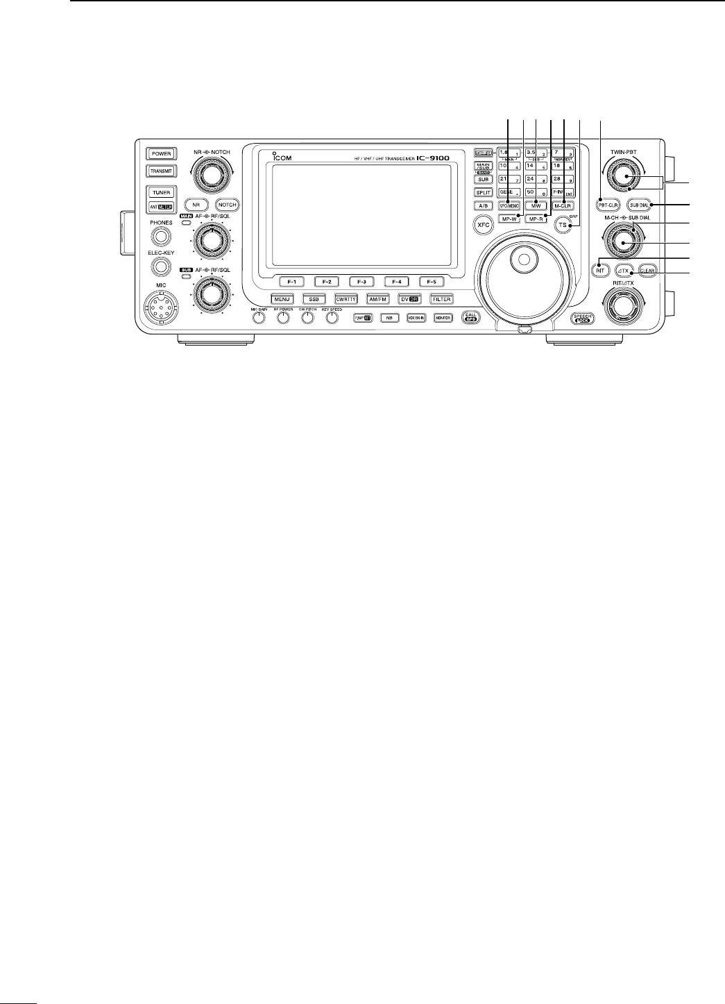
$40"4#,%!237)4#(;0"4#,2= (p. 75)
-ODE33"#72449!-
±
Push to display the filter passband width and
shifting value for 1 second on the function dis-
play.
±
Hold down for 1 second to reset the PBT set-
tings.
$50!33"!.$45.).'#/.42/,3;47).0"4=
(p. 75)
-ODE33"#72449!-
Adjusts the receiver’s IF filter passband width
using the DSP circuit.
sRotate this control or push [PBT-CLR] to display the
PBT settings (passband width and shifting value) for 2
seconds on the function display.
s(OLDDOWN;0"4#,2=FORSECONDTOCLEARTHE0"4
settings.
s4HEADJUSTMENTRANGEISHALFOFTHEPASSBANDWIDTHAND
the value is adjustable in 25 Hz steps for the SSB, CW,
AND2449MODESAND(ZSTEPSFORTHE!-MODE
s4HESECONTROLSFUNCTIONASAN)&SHIFTCONTROL
What is the PBT control?
The PBT function electronically modifies the IF passband
width to reject interference. This transceiver uses the DSP
circuit for the PBT function.
PBT2
PBT1
–
+
Low cutHigh cut Center
$635"$)!,37)4#(;35"$)!,= (p. 33)
Push to turn the SUB Dial function ON or OFF.
sh” appears when the SUB Dial function is ON.
$735"$)!,#/.42/,
OUTERCONTROLP
Rotate to change the SUB Band frequency.
Increases
Decreases
The [SUB DIAL] control’s tuning Band (MAIN or
SUB) and frequency steps differ, depending on
the combination of the SUB Dial function and
SUB Band setting mode status, and the status of
the quick tuning function. See page 33 for de-
tails.
$8 MEMORY CHANNEL CONTROL [M-CH]
INNERCONTROLP
Select a memory channel.
s2OTATECLOCKWISETOSELECTAHIGHERMEMORYCHANNEL
NUMBERROTATECOUNTERCLOCKWISETOSELECTALOWERMEM-
ory channel number.
Higher channel
Lower channel
$9 RIT SWITCH [RIT] (p. 69)
± Push to turn the RIT function ON or OFF.
s5SE;2)4∂TX] control to vary the RIT frequency.
± Hold down for 1 second to add the shift frequency
of the RIT function to or subtract it from the dis-
played frequency.
What is the RIT function?
The RIT (Receiver Incremental Tuning) shifts the receive
frequency without shifting the transmit frequency.
This is useful for fine tuning stations calling you off-fre-
quency or when you prefer to listen to slightly different-
sounding voice characteristics, etc.
%0 ∂TX SWITCH [∂TX] (p. 81)
± Push to turn the ∂TX function ON or OFF.
s5SE;2)4∂TX] control to vary the ∂TX frequency.
± Hold down for 1 second to add the shift fre-
quency of the ∂TX function to or subtract it from
the displayed frequency.
What is the ∂TX function?
∂TX shifts the transmit frequency without shifting the re-
ceive frequency. This is useful for simple split frequency
operation in CW, etc.
8
1
PANEL DESCRIPTION
1
The optional UT-121 is required for DV mode operation.
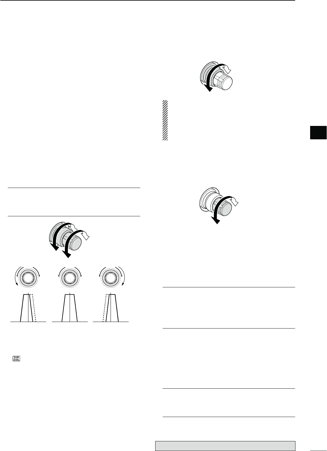
%1 MAIN DIAL (pp. 37, 161)
Rotate to change the displayed frequency, select
the Set mode settings, etc.
When the SUB Band setting mode is ON, rotat-
ing [MAIN DIAL] changes the SUB Band fre-
quency. (p. 33)
%2 CLEAR SWITCH [CLEAR] (pp. 69, 81)
Hold down for 1 second* to clear the RIT/∂TX shift
frequency.
* When the
“
Quick RIT Clear
” item
in the Set mode is
ON, push momentarily to reset the shift frequency.
(p. 164)
%3 RIT/∂TX CONTROL [RIT/∂TX] (pp. 69, 81)
When either or both the RIT/∂TX functions are ON,
rotate to adjust the RIT/∂TX frequency shift.
s2OTATETHECONTROLCLOCKWISETOINCREASETHEFREQUENCY
or counterclockwise to decrease the frequency.
s4HEFREQUENCYSHIFTRANGEISÒK(ZIN(ZSTEPS
The control tunes in 1 Hz steps when the operating fre-
quency readout is set to the 1 Hz step readout. How-
ever, the 1 Hz digit is not displayed on the frequency
shift readout.
Shift high
Shift low
%4 SPEECH/LOCK SWITCH [SPEECH/LOCK]
SPEECH SWITCH/PERATION(p. 45)
± Push to audibly announce the S-meter level, the
displayed frequency and the operating mode.
s4HE 3,EVEL ANNOUNCEMENT CAN BE TURNED /&&
in the “SPEECH S-Level” item of the Set mode.
(p. 164)
s7HEN2)4ANDOR∂TX are ON, the RIT/∂TX offset is
not included in the frequency announcement.
LOCK SWITCH/PERATION(p. 77)
± Hold down for 1 second to turn the Dial Lock
function ON or OFF.
s4HEFUNCTIONELECTRONICALLYLOCKSTHE-AINDIAL
sh” appears when the function is ON.
NOTE: The [SPEECH/LOCK] switch operation to
activate the voice synthesizer or the dial lock
functions can be replaced in the “[SPEECH/
LOCK] SW” item of the Set mode. (p. 164)
N Front panel (continued)
9
1PANEL DESCRIPTION
%3
%4
%2
%1
10
1
PANEL DESCRIPTION
1
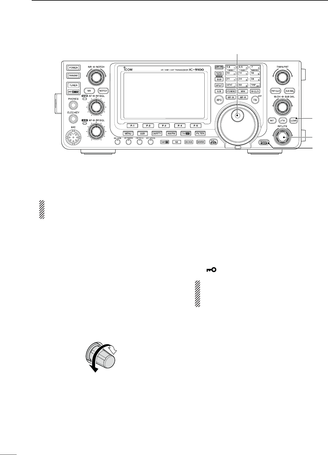
N2EARPANEL
qANTENNA CONNECTOR 1 [ANT1]
w ANTENNA CONNECTOR 2 [ANT2]
(pp. 24, 25, 158)
Connect a 50 ø antenna with a PL-259 plug con-
nector for the HF/50 MHz frequency band.
When using an optional AH-4 HF/50 MHz AUTO-
MATIC ANTENNA TUNER, connect it to the [ANT1]
connector. Connecting the AH-4 switches the in-
ternal antenna tuner from [ANT1] to [ANT2].
e-(Z"!.$!.4%..!#/..%#4/2
;-(Z!.4=(pp. 24, 158)
Connect a 1200 MHz 50 øantenna with a type-N
connector, when the optional UX-9100, 1200 MHz
band unit, is installed.
r
-!)."!.$%84%2.!,30%!+%2*!#+
;%8430-!).=
t
35""!.$%84%2.!,30%!+%2*!#+
;%843035"=
(p. 25)
Connect to an external speaker (4 to 8 ø).
By connecting an external speaker to each or both
jacks, the audio output for both the MAIN and SUB
Bands can be configured as shown below.
%XTERNALSPEAKER
CONNECTION MAIN AF 35"!&
No connection Internal speaker
To the MAIN jack External speaker Internal speaker
To the SUB jack Internal speaker External speaker
Both External speakers
y-(Z!.4%..!#/..%#4/2;-(Z!.4=
(pp. 24, 25, 158)
Connect a 50 øantenna with a type-N connector
for the 430 MHz frequency band.
u-(Z!.4%..!#/..%#4/2;-(Z!.4=
(pp. 24, 25, 158)
Connect a 50 øantenna with a PL-259 connector
for the 144 MHz frequency band.
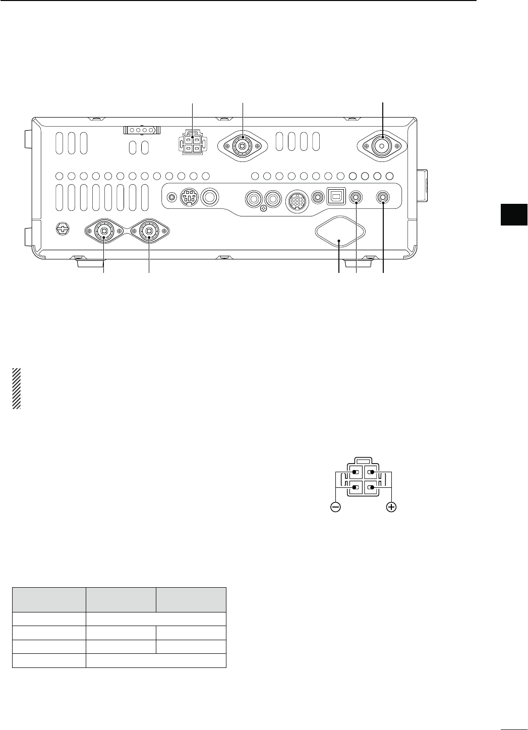
iDC POWER SOCKET [DC 13.8V] (p. 27)
Connect 13.8 V DC through the supplied DC power
cable.
Rear panel view
i u y
e trwq
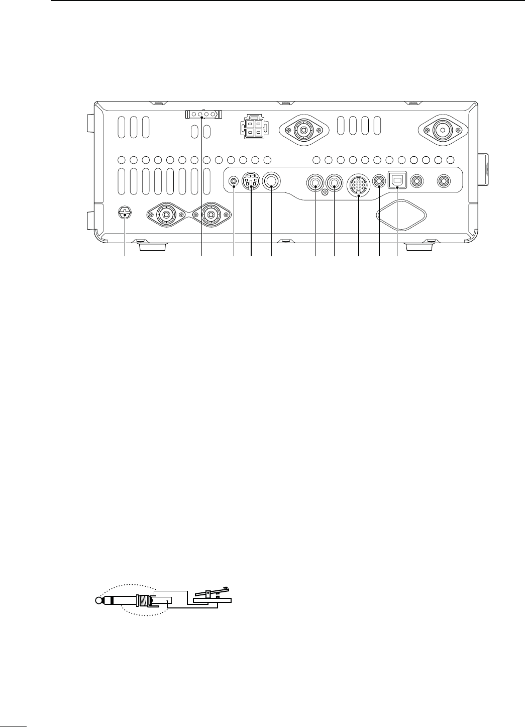
oGROUND TERMINAL [GND] (p. 22)
Connect this terminal to a ground to prevent electri-
cal shocks, TVI, BCI and other problems.
!0 TUNER CONTROL SOCKET [TUNER] (p. 29)
Connect the control cable from an optional AH-4 HF/
50 MHZ AUTOMATIC ANTENNA TUNER.
!1 DATA1 JACK [DATA1] (p. 26, 168)
± Connect a PC through the optional OPC-1529R
DATA COMMUNICATION CABLE, for low-speed data
communication in the DV mode. (p. 117)
± Connect a GPS receiver through the optional
OPC-1529R DATA COMMUNICATION CABLE, for
GPS operation. (p. 121)
!2 DATA2 SOCKET [DATA2] (pp. 26, 171)
Connect a TNC (Terminal Node Controller), etc. for
high speed data communications.
!3 STRAIGHT KEY JACK [KEY] (p. 24)
Connect a straight key or external electronic keyer
output using a standard 1⁄4 inch plug.
s;%,%#+%9= ON THE FRONT PANEL CAN BE USED FOR A
straight key or external electronic keyer. First you must
turn OFF the internal electronic keyer in the Keyer Set
mode. (p. 55)
+
_
!4 ALC INPUT JACK [ALC] (p. 25)
Connect to the ALC output jack of a non-Icom linear
amplifier.
!5 SEND CONTROL JACK [SEND] (p. 25)
When transmitting, goes to ground to control an ex-
ternal unit, such as a non-Icom linear amplifier.
!6 ACCESSORY SOCKET [ACC]
Connect control lines for external equipment such
as a linear amplifier, an automatic antenna selector/
tuner, a TNC for data communications, etc.
s3EEPAGEFORSOCKETINFORMATION
!7 CI-V REMOTE CONTROL JACK [REMOTE]
(pp. 26, 183)
± Connect
a PC, using the optional CT-17
CI
-
V
LEVEL
CONVERTER
, for external control of the transceiver.
± Use for transceive function with another Icom
CI-V transceiver or receiver.
When the transceive function is set to ON,
changing the frequency, operating mode, etc.
on the IC-9100 automatically changes those
settings on other Icom transceivers or receivers,
and vice versa. (p. 167)
± Connect another IC-9100, using a mini plug
cable*, for transceiver to transceiver cloning.
* Purchase separately
11
1PANEL DESCRIPTION
!8!6 !7!5!4
!3!2!1
o
N Rear panel (Continued)
!0

12
1
PANEL DESCRIPTION
1
!853"5NIVERSAL3ERIAL"US0/24
;53"=
Using a USB cable, connect a PC to do the follow-
ing:
- Input modulation (p. 167)
- Remotely control the transceiver using CI-V com-
mands (p. 183)
- Send the received audio to the PC
-
Send the decoded characters to the PC
(pp. 59, 167)
- Low-speed data communication in the DV mode
(p. 167)
- Cloning using the optional CS-9100 CLONING SOFT-
WARE (p. 182)
!BOUTTHE53"DRIVER
The USB driver and the installation guide can be
downloaded from our website.
± http://www.icom.co.jp/world/index.html
The following items are required:
PC
s-ICROSOFT® Windows® XP,
Microsoft® Windows Vista® or
Microsoft® Windows® 7 OS
s!53"ORPORT
/THERITEMS
s53"CABLEPURCHASESEPARATELY
s0#SOFTWARESUCHASOPTIONAL23"!OR#3
9100)
NEVER connect the transceiver to a PC until the
USB driver installation has been completed.
!BOUTTHEMODULATIONINPUT
Select “USB” in the Set mode item “DATA OFF
MOD” or “DATA MOD.” The modulation input level
from the USB jack can be set in the Set mode item
“USB MOD Level.” (p. 167)
13
1PANEL DESCRIPTION
N Rear panel (Continued)
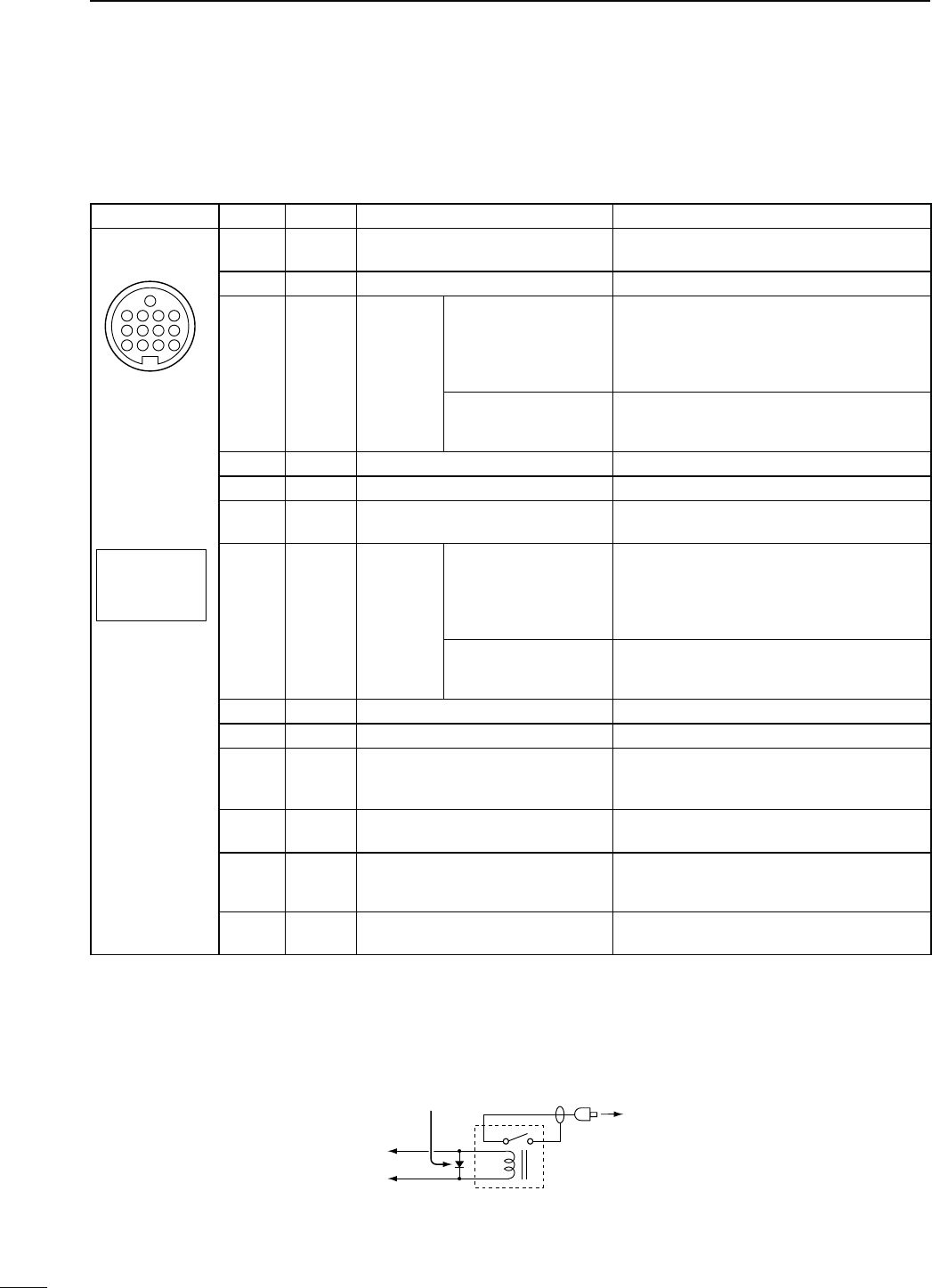
D!##SOCKETINFORMATION
s!##SOCKET
ACC
PIN No.
NAME DESCRIPTION SPECIFICATIONS
1234
8765
9
10 11 12
13
Rear panel view
Color refers to
the cable strands
of the supplied
cable.
q brown
w red
e orange
r yellow
t green
y blue
u purple
i
o
!0
!1
!2
!3
gray
white
black
pink
light
blue
light
green
18 VRegulated 8 V output. Output voltage
Output current : 8 V ± 0.3 V
: Less than 10 mA
2 GND Connects to ground. ———
3HSEND
*1, 2 Input/out-
put pin.
An external equipment
controls the transceiver.
When this pin goes low,
the transceiver trans-
mits.
Input voltage (High)
Input voltage (Low)
Current flow
: 2.0 V to 20.0 V
: –0.5 V to +0.8 V
: Max. 20 mA
The transceiver outputs a
low signal to control exter-
nal equipment.
Output voltage (Low)
Current flow : Less than 0.1 V
: Max. 200 mA
4NC ——— ———
5 BAND Band voltage output. Output voltage : 0 to 8 V
6 ALC ALC voltage input. Control voltage
Input impedance : –3 V to 0 V
: More than 3.3 k˘
7VSEND
*1, 2 Input/out-
put pin.
An external equipment
controls the transceiver.
When this pin goes low,
the transceiver trans-
mits.
Input voltage (High)
Input voltage (Low)
Current flow
: 2.0 V to 20.0 V
: –0.5 V to +0.8 V
: Max. 20 mA
The transceiver outputs a
low signal to control exter-
nal equipment.
Output voltage (Low)
Current flow : Less than 0.1 V
: Max. 200 mA
8 13.8 V 13.8 V output when power is ON. Output current : Less than 1 A
9 NC ——— ———
10 FSKK #ONTROLS2449KEYING
“High” level
“Low” level
Output current
: More than 2.4 V
: Less than 0.6 V
: Less than 2 mA
11 MOD Modulator input. Input impedance
Input level : 10 k˘
: Approx. 100 mV rms
12 AF*3AF detector output.
Fixed level, regardless of the [AF]
control position.
Output impedance
Output level : 4.7 k˘
: 100 to 300 mV rms
13
SQL S*
3
Squelch output.
Grounded when squelch opens.
SQL open
SQL closed : Less than 0.3 V/5 mA
: More than 6.0 V/100 µA
*1 When the SEND terminal controls the inductive load (such as a relay), a counter-electromotive force can cause
the transceiver’s malfunction or damage. To prevent this, we recommend adding a switching diode, such as an
“1SS133,” on the load side of the circuit to the counter-electromotive force absorption.
When the diode is added, a switching delay of the relay may occur. Be sure to check its switching action before
operation.
eHSEND or
uVSEND
i13.8 V
ACC socket
Relay
Switching diode To a non-Icom
linear amplifier
e
*2 VSEND is used for the 144 MHz, 430 MHz, and 1200 MHz bands, and HSEND is used for the HF/50 MHz bands
BYDEFAULT9OUCANCHANGETHISSETTINGINh63%.$3ELECTvOFTHE3ETMODEP
*34HEPIN!&ANDPIN31,3OUTPUTCAPABILITIESAREFORTHE-!)."ANDS!&ANDSQUELCHBYDEFAULT9OU
can change this setting in “ACC AF/SQL Select” of the Set mode. (p. 166)
14
1
PANEL DESCRIPTION
1
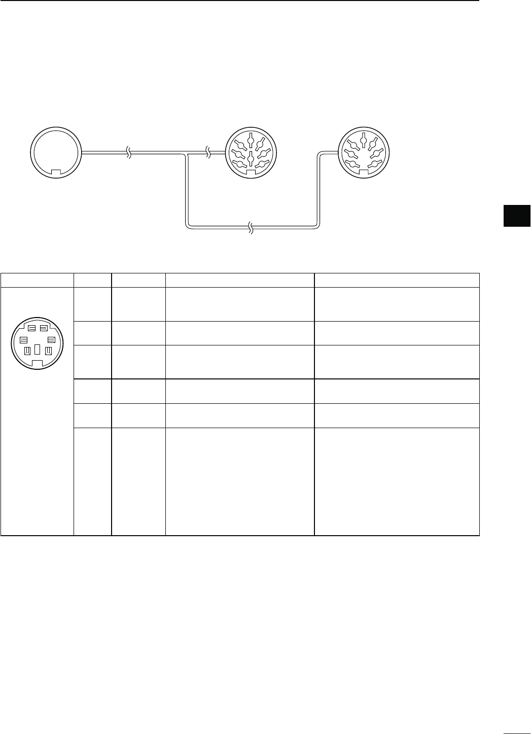
D$!4!SOCKETINFORMATION
DATA2
PIN No.
NAME DESCRIPTION SPECIFICATIONS
qw
er
ty
Rear panel view
1DATA IN Input terminal for data transmit.
(1200 bps: AFSK/
9600 bps: G3RUH, GMSK)
Input level (1200 bps)
Input level (9600 bps) : 100 mV
: 0.2 to 0.5 Vp-p
2 GND Common ground for DATA IN, DATA
OUT and AF OUT. ———
3PTT PTT terminal for packet operation.
Connect to ground to activate the
transmitter.
Input voltage (High)
Input voltage (Low) : 2.0 V to 20.0 V
: –0.5 V to +0.8 V
4
DATA OUT
*
Data out terminal for 9600 bps op-
eration only.
Output impedance
Output level : 10 k˘
: 1.0 Vp-p
5AF OUT*Data out terminal for 1200 bps op-
eration only.
Output impedance
Output level : 4.7 k˘
: 100–300 mV rms
6SQL*
Squelch out terminal. This pin is
grounded when the transceiver re-
ceives a signal which opens the
squelch.
s4OAVOIDINTERFERINGTRANSMISSIONS
connect squelch to the TNC to inhibit
transmission when squelch is open.
s+EEP2&GAINATANORMALLEVELOTH-
erwise a “SQL” signal will not be out-
put.
SQL open
SQL closed
: Less than 0.3 V/
5 mA
: More than 6.0 V/
100 µA
* The pin 4 (DATA), pin 5 (AF) and pin 6 (SQL) output capabilities are for the MAIN Band’s AF and squelch by de-
FAULT9OUCANCHANGETHISSETTINGINh$!4!!&31,3ELECTvOFTHE3ETMODEP
8
1
2
3
4
7
6
5
1
2
3
4
7
6
5
qwer
tyui
o!0 !1 !2
!3 Connect to ACC socket ACC 1 ACC 2
q FSKK
w GND
e HSEND
r MOD
t AF
y SQLS
u 13.8 V
i ALC
q 8 V
w GND
e HSEND
r BAND
t ALC
y VSEND
u 13.8 V
s7HENCONNECTINGTHE!##CONVERSIONCABLE/0#
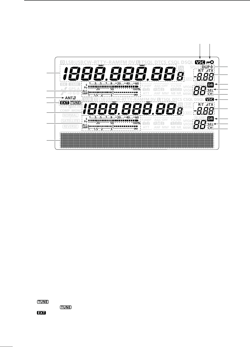
N,#$DISPLAY
!2!0
q
t
w
q
r
w
e
y
y
o
o
!1
u
i
!0
u
i
15
1PANEL DESCRIPTION
qFREQUENCY READOUTS
Displays the operating frequency.
s7HENTHEQUICKTUNINGICONhZ” is displayed, the fre-
quency changes in pre-set kHz or 1 MHz quick tuning
steps. (p. 38)
s7HENTHEQUICKTUNINGICONhZ” is not displayed, the fre-
quency changes in 10 Hz or 1 Hz steps. (pp. 37, 39)
wMULTI-FUNCTION METER INDICATION
±Displays the signal strength while receiving.
±Displays the relative output power, SWR, ALC or
compression levels while transmitting.
±When the Meter Peak Hold function is ON, the
peak level of a received signal strength or the
output power is displayed for approximately 0.5
seconds.
eANTENNA ICON (p. 158)
Displays which antenna connector is selected for
HF/50 MHz.
sh!.4v APPEARS WHEN THE ;!.4= CONNECTOR IS SE-
lected.
sh!.4v APPEARS WHEN THE ;!.4= CONNECTOR IS SE-
lected.
r ANTENNA TUNER ICONS (pp. 159, 160)
±“” appears when the antenna tuner is
TURNED/.h ” blinks during tuning.
±“” appears when the optional AH-4 external
antenna tuner is connected to the [ANT1] con-
nector, and [ANT1] is selected.
tFUNCTION DISPLAY (p. 19)
Shows the function of the function switches ([F1]–
[F5])
,
Set mode items and IF passband width.
yMEMORY CHANNEL READOUTS
Displays the selected memory channel.
uSELECT MEMORY CHANNEL ICON
±Appears when the selected memory channel is
set as a select memory channel.
(p. 151)
±Appears when the repeater can be selected as
the access repeater in the DR mode.
(p. 100)
iDR MODE ICON (p. 43)
Appears
when the DR mode is selected.
oRIT/∂TX ICONS (pp. 69, 81)
±“RIT” appears when the RIT function is turned
ON.
±“∂TX” appears when the ∂TX function is turned
ON.
±Shows the shift frequency of the RIT or ∂TX
function.
!0 VOICE SQUELCH CONTROL ICON (p. 146)
Appears when the VSC (Voice Squelch Control)
function is turned ON.
!1 DUPLEX ICON (p. 65)
“DUP+” appears when plus duplex, “DUP –” ap-
pears when minus duplex (repeater) operation is
selected.
!2 KEY LOCK ICON (p. 77)
Appears when the Key Lock function is turned ON.
16
1
PANEL DESCRIPTION
1
!5 !3!4
!
5
@0
!6
!8
!9
!
4
!
3
!7
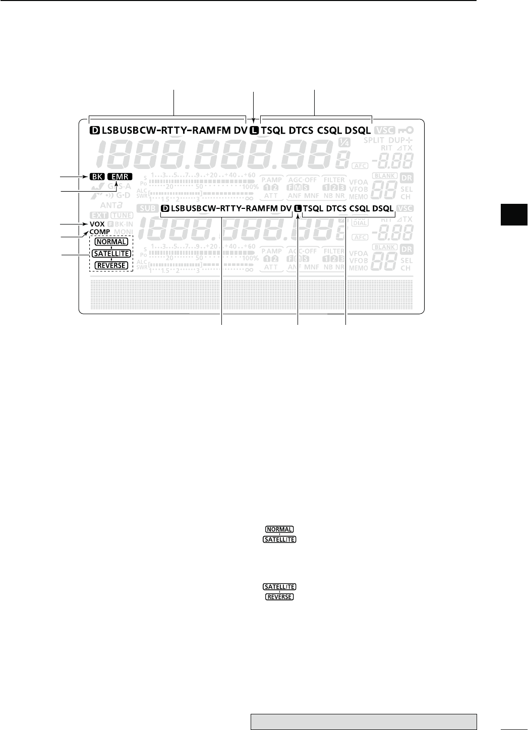
!3 TONE SQUELCH ICONS
-ODE&-
±“T” appears when the repeater tone function is
ON. (p. 65)
±“TSQL” appears when the tone squelch function
is ON. (p. 62)
±“DTCS” appears when the DTCS code squelch
function is ON. (p. 63)
-ODE$6
±“DSQL” appears when the digital call sign squelch
function is ON. (p. 114)
±“CSQL” appears when digital code squelch func-
tion is ON. (p. 114)
!4 PACKET LOSS ICON
-ODE$6
Appears when the Packet Loss occurs.
s7HILEOPERATINGVOICECOMMUNICATIONORLOWSPEEDDATA
communication via the internet network, some packets
may be lost due to network error (poor data throughput
performance). (p. 117)
!5 MODE ICONS (p. 43)
Displays the selected operating mode.
shD” appears when SSB data, AM data or FM data mode
is selected.
!6"2%!+).)#/. (p. 116)
±Appears when the Break-in function is turned
ON.
sThe Break-in function allows you to break into a con-
versation, where the two original stations are com-
municating with call sign squelch enabled.
±Blinks when receiving a break-in call.
!7 EMR MODE ICON (p. 115)
±Appears when the EMR (Enhanced Monitor Re-
ceive) communication mode is selected.
s)NTHE%-2COMMUNICATIONMODENOCALLSIGNSET-
ting is necessary when operating in the DV mode.
±Blinks when receiving an EMR signal.
!8 VOX ICON (p. 78)
Appears when the VOX function is activated.
!9 SPEECH COMPRESSOR ICON (p. 80)
Appears when the Speech Compressor function is
turned ON.
@0 SATELLITE ICON (p. 153)
Appears while the satellite mode is selected.
The optional UT-121 is required for DV mode operation.
: Normal satellite mode is selected.
s7HEN;-!).$)!,= is rotated, both down-
link and uplink frequencies simultaneously
increase or decrease in the same step.
: Reverse satellite mode is selected.
s7HEN;-!).$)!,= is rotated to the right,
downlink frequency increase, and uplink
frequency decrease in the same step.
s7HEN;-!).$)!,= is rotated to the left,
downlink frequency decrease, and uplink
frequency increase in the same step.
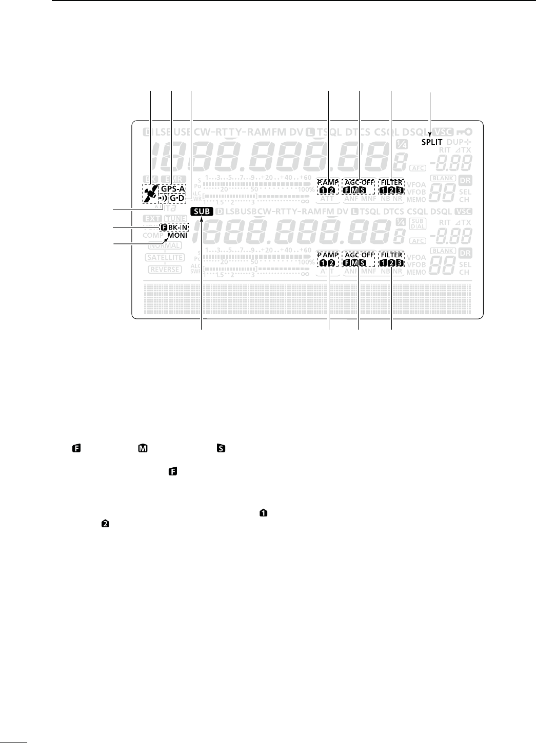
17
1PANEL DESCRIPTION
N LCD display (Continued)
@2 @1@3@4@6 @5@7
#
1
@
4
@
3
@
2
@9
@8
#0
@1 SPLIT ICON (p. 82)
Appears when the Split function is turned ON.
@2 DSP FILTER ICON (p. 73)
Displays the selected IF filter.
@3 AGC ICONS (p. 72)
Displays the selected AGC time constant.
shvFOR!'#FASTh vFOR!'#MIDDLEh vFOR!'#SLOW
“-OFF” for AGC OFF.
s)NTHE&-AND$6MODEh ” for AGC fast is fixed.
@4 PREAMP ICON (p. 71)
Appears when a preamplifier is turned ON.
s)N(&-(ZFREQUENCYBANDEITHERh0!-0 ” or
“P. AMP ” is displayed when the preamp 1 or preamp 2
is ON.
@5 GPS DATA COMMUNICATION ICON
Appears while the GPS data communication func-
tion is selected in the “GPS Out” item of the Set
mode. (p. 168).
s!'03DATAFROMTHE'03RECEIVERWHICHISCONNECTED
to the [DATA1] jack, is output to the [USB] port.
@6 GPS TX ICON (p. 134)
±“GPS” appears when the GPS transmission
mode is set to GPS.
±“GPS-A” appears when GPS transmission mode
is set to GPS-A.
@7 GPS ICON (p. 132)
±Appears when a valid position data is received
from a GPS receiver that is connected to the
[DATA1] jack.
±Blinks when an invalid data is received from the
GPS receiver.
@8 GPS ALARM ICON (p. 130)
Appears when the GPS alarm function is turned
ON.
@9"2%!+).)#/.(p. 79)
±“F BK-IN” appears when the Full Break-in func-
tion is turned ON.
±“BK-IN” appears when the Semi Break-in func-
tion is turned ON.
#0 MONITOR ICON (p. 81)
Appears when the Monitor function is turned ON.
#135")#/.(p. 33)
Appears when the SUB Band setting mode is ON.
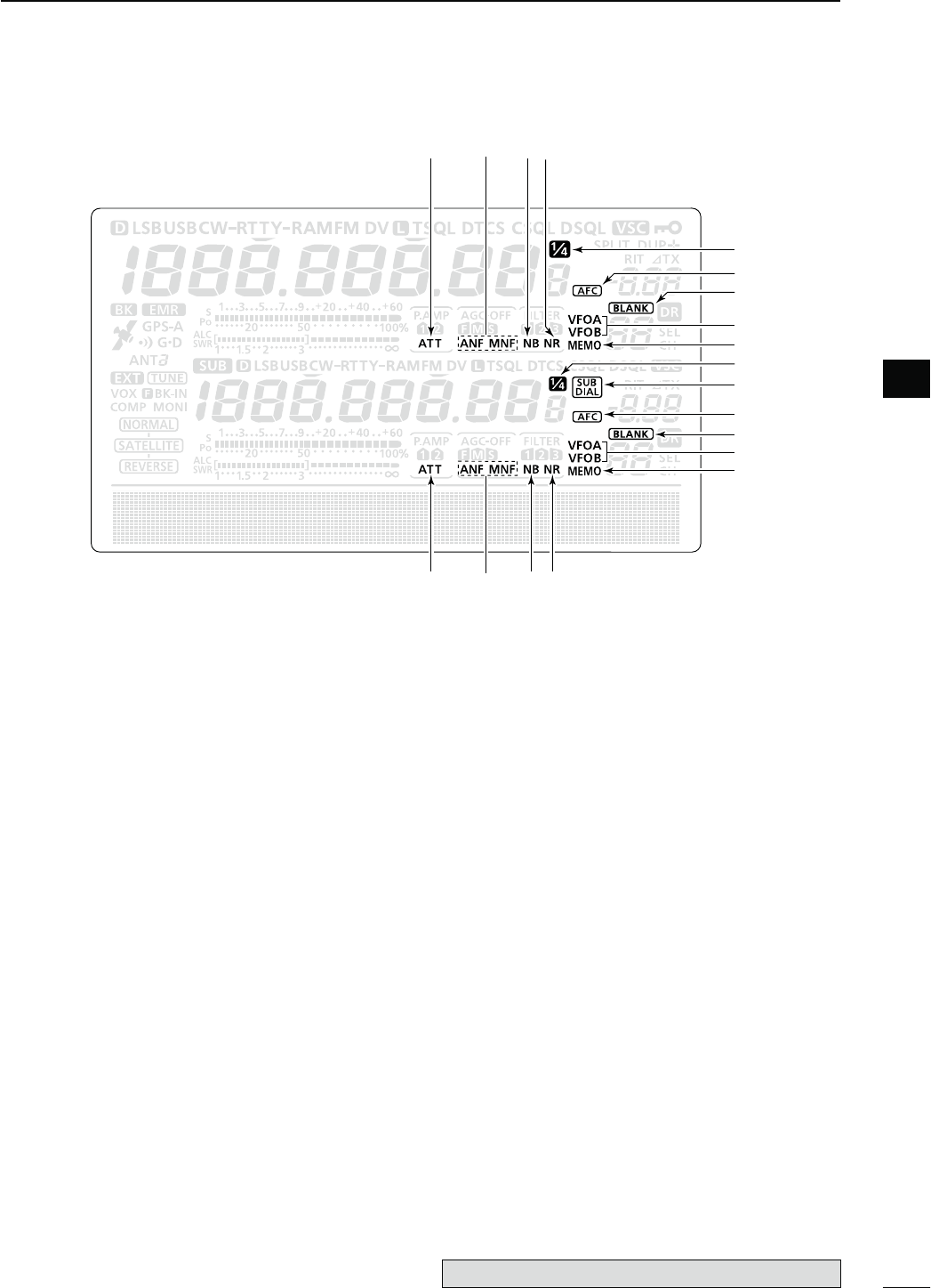
18
1
PANEL DESCRIPTION
1
#4#5
#
5
#
3
#
2
$1
#8
#7
#6
$0
#9
#3#2
#
4
#7
#6
$1
#8
#9
#2 NOISE REDUCTION ICON (p. 77)
Appears when the Noise Reduction function is
turned ON.
#3./)3%",!.+%2)#/.(p. 76)
Appears when the Noise Blanker function is turned
ON.
#4 NOTCH ICONS (p. 77)
-ODE33"#72449!-
±“MNF” appears when the Manual Notch function
is turned ON.
-ODE33"!-&-
±“ANF” appears when the Automatic Notch func-
tion is turned ON.
#5 ATTENUATOR ICON (p. 71)
Appears when the Attenuator function is turned
ON.
#6 MEMORY ICON (pp. 34, 139)
Appears when the memory mode is selected.
#7 VFO ICONS (p. 34)
Displays whether VFO A or VFO B is selected.
#8",!.+-%-/29)#/.(p. 139)
Appears when the selected memory channel is
blank.
#9 AFC ICON (p. 69)
-ODE&-$6
Appears when the AFC (Automatic Frequency Con-
trol) function is turned ON.
$035"$)!,)#/.(p. 33)
Appears when the SUB Dial function is turned ON.
$1 1⁄4TUNING DIAL SPEED ICON (p. 39)
-ODE33"$#72449
Appears when the tuning dial speed is set so that
one rotation is equal to 1⁄4 of the normal rotation.
s4HISFUNCTIONISAVAILABLEONLYWHENTHEQUICKTUNING
function is turned OFF.
The optional UT-121 is required for DV mode operation.
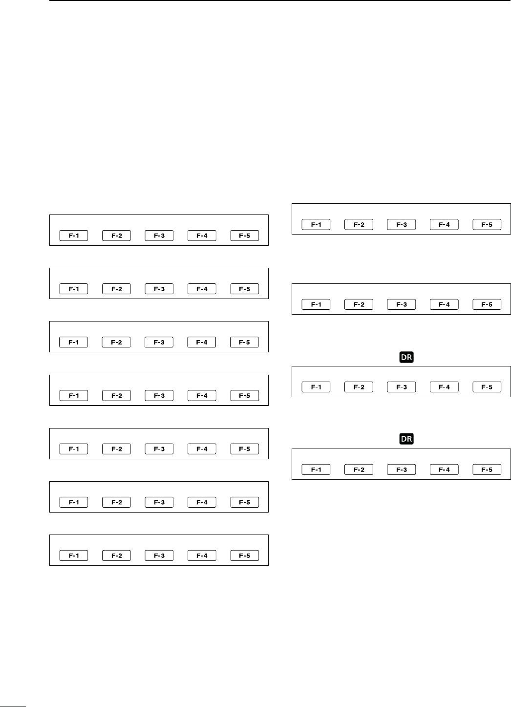
19
1PANEL DESCRIPTION
N&UNCTIONDISPLAY
Push [MENU] to toggle the function display menu.
s4HESETOFFUNCTIONSASSIGNEDTOTHEFUNCTIONSWITCHES
change according to the selected menu and operat-
ing mode.
s)NTHE$6MODE-menu 3) display can be selected
after selecting menu 2.
s)NTHE$2MODETHE$AND$DISPLAYSCANBESE-
lected.
Push to select the functions displayed in the display
above switches ([F-1] to [F-5])
s&UNCTIONSVARYDEPENDINGONTHEOPERATINGMODE
D--ENUDISPLAY
-/$%33"
AGC DUP COMP TBW SCP
-/$%33"$
AGC DUP 1 ⁄ 4 SCP
<MODE> CW
AGC DUP 1 ⁄ 4 +%9 SCP
<MODE> RTTY
AGC DUP 1 ⁄ 4 2449 SCP
<MODE> AM
AGC DUP SCP
<MODE> FM
AGC DUP AFC TON SCP
<MODE> DV
AGC DUP AFC DSQ SCP
D--ENUDISPLAY
SCAN MEM SWR TCON VSC
D--ENUDISPLAY
<MODE> DV
CS CD R>CS UR DSET
D$DISPLAY
<MODE> DV (Only when “ ” is displayed.)
CS CD R>CS UR DSET
D$DISPLAY
<MODE> DV (Only when “ ” is displayed.)
SCAN SEL AFC DSQ TCON
20
1
PANEL DESCRIPTION
1
D&UNCTIONKEYSON--ENUDISPLAY
!'#+%9;!'#=& (p. 72)
±Push to select the time constant of the AGC circuit.
±Hold down for 1 second to display the “AGC”
screen.
$50,%8+%9;$50=&(p. 65)
±Push to select the duplex direction, or to turn OFF
the function.
sh$50nvORh$50vISDISPLAYEDDURINGDUPLEXOPERATION
±In the FM mode, hold down for 1 second to turn the
one-touch repeater function ON or OFF.
30%%#(#/-02%33/2+%9;#/-0=&(p. 80)
-ODE33"
±Push to turn the speech compressor function ON
or OFF.
sh#/-0vISDISPLAYEDWHENTHESPEECHCOMPRESSORIS
ON.
±Hold down for 1 second to display the “COMP”
screen.
1⁄4 TUNING FUNCTION KEY [1⁄4=&(p. 39)
-ODE33"$#72449
Push to turn the 1⁄4 Tuning function ON or OFF.
sh ” is displayed when the 1⁄4 Tuning function is ON.
!&#+%9;!&#=&(p. 69)
-ODE&-$6
Push to turn the AFC function ON or OFF.
sh ” is displayed when the AFC function is ON.
42!.3-)33)/."!.$7)$4(+%9;4"7=&
(p. 80)
-ODE33"
±Push to display the selected
transmission band-
width.
±Hold down for 1 second
to select the transmission
bandwidth.
s"ANDWIDTHISSELECTABLEFROMWIDE7)$%MIDDLE-)$
and narrow (NAR).
-%-/29+%9%2-%.5+%9;+%9=&(p. 50)
-ODE#7
Push to display the
“
+%9
”
screen (memory keyer) or the
“
SEND
”
SCREENKEYERSENDDEPENDINGONTHEh+%9%2
1st Menu” option in the Set mode
(p. 165)
.
2449-%.5+%9;2449=&(p. 57)
0USHTODISPLAYTHEh2449vSCREEN
4/.%315%,#(+%9;4/.=&(pp. 62–64)
-ODE&-
±Push to select a tone function between subaudible
(repeater) tone, tone squelch and DTCS code.
±Hold down for 1 second to display the “TON” screen
of the selected tone function.
$)')4!,315%,#(+%9;$31=&(p. 114)
-ODE$6
±Push to select a digital squelch function between
digital call sign squelch and digital code squelch.
±Hold down for 1 second to display the “DSQ” screen
(digital squelch).
"!.$3#/0%&5.#4)/.+%9;3#0=&(p. 70)
Push to display the “SCP” screen (band scope).
D&UNCTIONKEYSON--ENUDISPLAY
3#!.+%9;3#!.=&(p. 147)
Push to display the “SCAN” screen.
-%-/29.!-%+%9;-%-=&(p. 143)
Push to display the “MEM” screen (memory name
edit).
372'2!0(&5.#4)/.+%9;372=&(p. 84)
Push to display the “SWR” screen.
4/.%#/.42/,3%4-/$%+%9;4#.=&
(p. 169)
Push to enter the Tone Control Set mode.
63#&5.#4)/.+%9;63#=&(p. 146)
-ODE33"!-&-
Push to turn the VSC (Voice Squelch Control) function
ON or OFF.
sh ” appears when the VSC function is ON.
The optional UT-121 is required for DV mode operation.

21
1PANEL DESCRIPTION
N Function display (Continued)
D&UNCTIONKEYSON--ENUDISPLAY
-ODE$6
#!,,3)'.+%9;#3=&(p. 85)
Push to display the “CS” screen.
s4HECURRENTCALLSIGNFOR$6OPERATIONAPPEARS
#!,,2%#/2$+%9;#$=&(p. 95)
Push to display the “CD” screen.
s4HECALLRECORDCHANNEL appears. (RX01 to RX20)
2#3+%9;2#3=&(p. 96)
Hold down for 1 second to copy and set the previously
received station call sign as the station call sign for
making a call.
52+%9;52=&(p. 101)
Push to toggle the UR and the repeater call sign selection
screen.
s4HEDESIREDSTATIONORREPEATERCALLSIGNCANBESELECTED
$3%4+%9;$3%4=&(p. 118)
Push to enter the DV Set mode.
D&UNCTIONKEYSON$DISPLAY
-ODE$6(Only when “ ” is displayed.)
#!,,3)'.+%9;#3=&(p. 85)
Push to display the “CS” screen.
s4HECURRENTCALLSIGNFOR$6OPERATIONAPPEARS
#!,,2%#/2$+%9;#$=&(p. 95)
Push to display the “CD” screen.
s4HE28CALLSIGNDATAAPPEARS
2#3+%9;2#3=&(p. 96)
Hold down for 1 second to copy and set the previously
received station call sign as the station call sign for
making a call.
52+%9;52=&(p. 101)
Push to toggle the UR and the repeater call sign selection
screen.
s4HEDESIREDSTATIONORREPEATERCALLSIGNCANBESELECTED
$3%4+%9;$3%4=&(p. 118)
Push to enter the DV Set mode.
D&UNCTIONKEYSON$DISPLAY
-ODE$6(Only when “ ” is displayed.)
3#!.+%9;3#!.=&
±Push to start or cancel the Access repeater scan.
(p. 100)
±Hold down for 1 second
to enter the Scan Set mode.
(p. 147)
3%,+%9;3%,=&(p. 100)
Hold down for 1 second
to
set the repeater as a ac-
cess repeater scan target.
!&#+%9;!&#=&(p. 69)
Push to turn the AFC function ON or OFF.
sh ” is displayed when the AFC function is ON.
$31+%9;$31=&(p. 114)
±Push to select a digital squelch function between
digital call sign squelch and digital code squelch.
±Hold down for 1 second to display the “DSQ” screen
(digital squelch).
4#/.+%9;4#/.=&(p. 169)
Push to enter the Tone Control Set mode.
The optional UT-121 is required for DV mode operation.
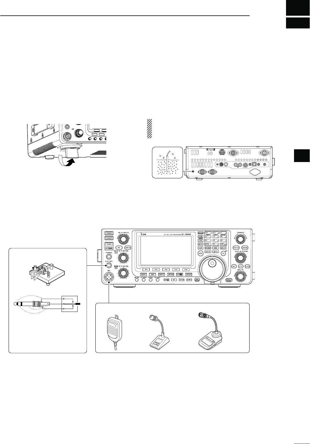
2
22
INSTALLATION AND CONNECTIONS
2
N3ELECTINGALOCATION
Select a location for the transceiver that allows ade-
quate air circulation, free from extreme heat, cold, or
vibrations, and away from TV sets, TV antenna ele-
ments, radios and other electromagnetic sources.
The base of the transceiver has adjustable feet for
desktop use. Set the feet to one of two angles, to meet
your operating preference.
N'ROUNDING
To prevent electrical shock, television interference
(TVI), broadcast interference (BCI) and other prob-
lems, ground the transceiver using the GROUND ter-
minal on the rear panel.
For best results, connect a heaviest gauge wire or
strap to a long ground rod. Make the distance between
the [GND] terminal and ground as short as possible.
RWARNING! NEVER connect the [GND] ter-
minal to a gas or electric pipe, since the connection
could cause an explosion or electric shock.
[GND]
N%LECTRONICKEYERANDMICROPHONECONNECTIONS
(dot)
(com)
(dash) MICROPHONES (p. 30)
HM-36 SM-50
(Option)
ELEC-KEY
A straight key can also be
connected. However, “Straight
key” must be selected in the
“Keyer Type” item of the Keyer
Set mode. (p. 55)
SM-30
(Option)
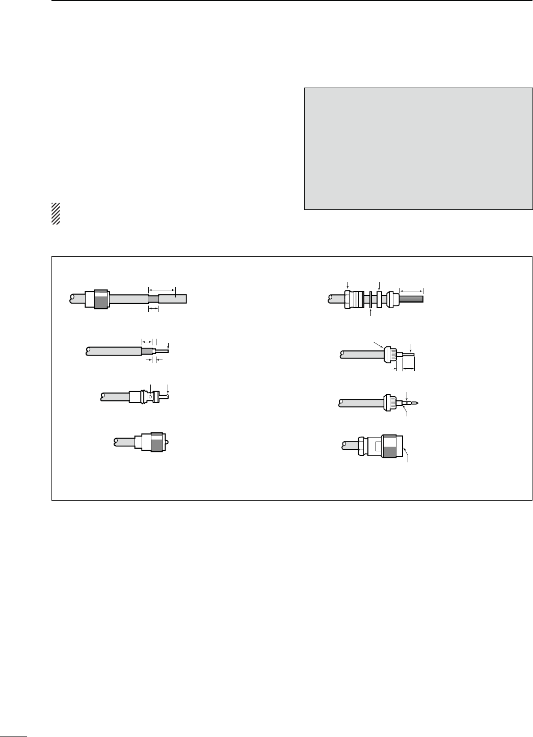
23
2INSTALLATION AND CONNECTIONS
PL-259 CONNECTOR INSTALLATION EXAMPLE TYPE-N CONNECTOR INSTALLATION EXAMPLE
Slide the coupling ring
down. Strip the cable
jacket and tin the shield.
Slide the connector
body on and solder it.
Screw the coupling
ring onto the connec-
tor body.
Strip the cable as
shown at left. Tin the
center conductor.
q
w
e
r
Slide the nut, rubber
gasket and clamp
over the coaxial cable,
then cut the end of the
cable evenly.
Strip the cable and
fold the braid back
over the clamp.
Tin the center con-
ductor. Install the
center conductor pin
and solder it.
Carefully slide the
plug body into place
aligning the center
conductor pin on the
cable. Tighten the nut
onto the plug body.
q
w
e
r
15 mm
3 mm 6 mm
30 mm
10 mm (tin here)
10 mm
1–2 mm
solder solder
tin
Coupling ring
No space
Solder hole
Be sure the center conductor is
the same height as the plug body.
Clamp Center
conductor
Washer
Nut Rubber gasket
30 mm (9⁄8 in) 10 mm (3⁄8 in) 1–2 mm (1⁄16 in)
N!NTENNACONNECTION
For radio communications, the antenna is of critical
importance, along with output power and receiver sen-
sitivity. Select a well-matched 50 ø antenna and co-
axial cable feedline. We recommend 1.5:1 or better of
Voltage Standing Wave Ratio (VSWR) on your operat-
ing bands. The transmission line should be a coaxial
cable.
When using a single antenna (for the HF/50 MHz
band), use the [ANT1] connector.
CAUTION: Protect your transceiver from lightning
by using a lightning arrestor.
!NTENNA372
Each antenna is tuned for a specified frequency
range and the SWR usually increases outside the
range. When the SWR is higher than approximately
2.0:1, the transceiver automatically reduces the TX
power to protect the final transistors. In that case, an
antenna tuner is useful to match the transceiver and
antenna. Low SWR allows full power for transmit-
ting. The IC-9100 has an SWR meter to continuously
monitor the antenna SWR.
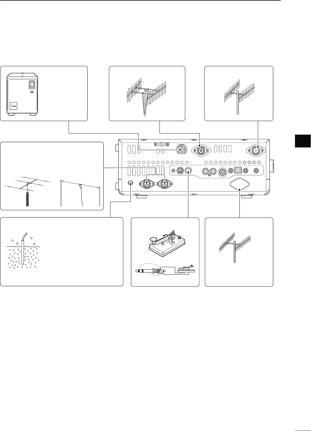
24
2
INSTALLATION AND CONNECTIONS
2
N2EQUIREDCONNECTIONS
D2EARPANEL
+
_
DC POWER
SUPPLY
(p. 27)
;-(Z!.4=(p. 158) ;-(Z!.4=(p. 158)
PS-126
Use the heaviest possible
gauge wire or strap and
make the connection as
short as possible.
Grounding prevents elec-
trical shocks, TVI and
other problems.
GROUND (p. 22) STRAIGHT KEY ;-(Z!.4=(p. 158)
The optional UX-9100
is required.
(&-(Z!.4%..!(p. 158)
Connection example:
[ANT1] for 1.8–18 MHz bands antenna
[ANT2] for 21–28 MHz bands antenna
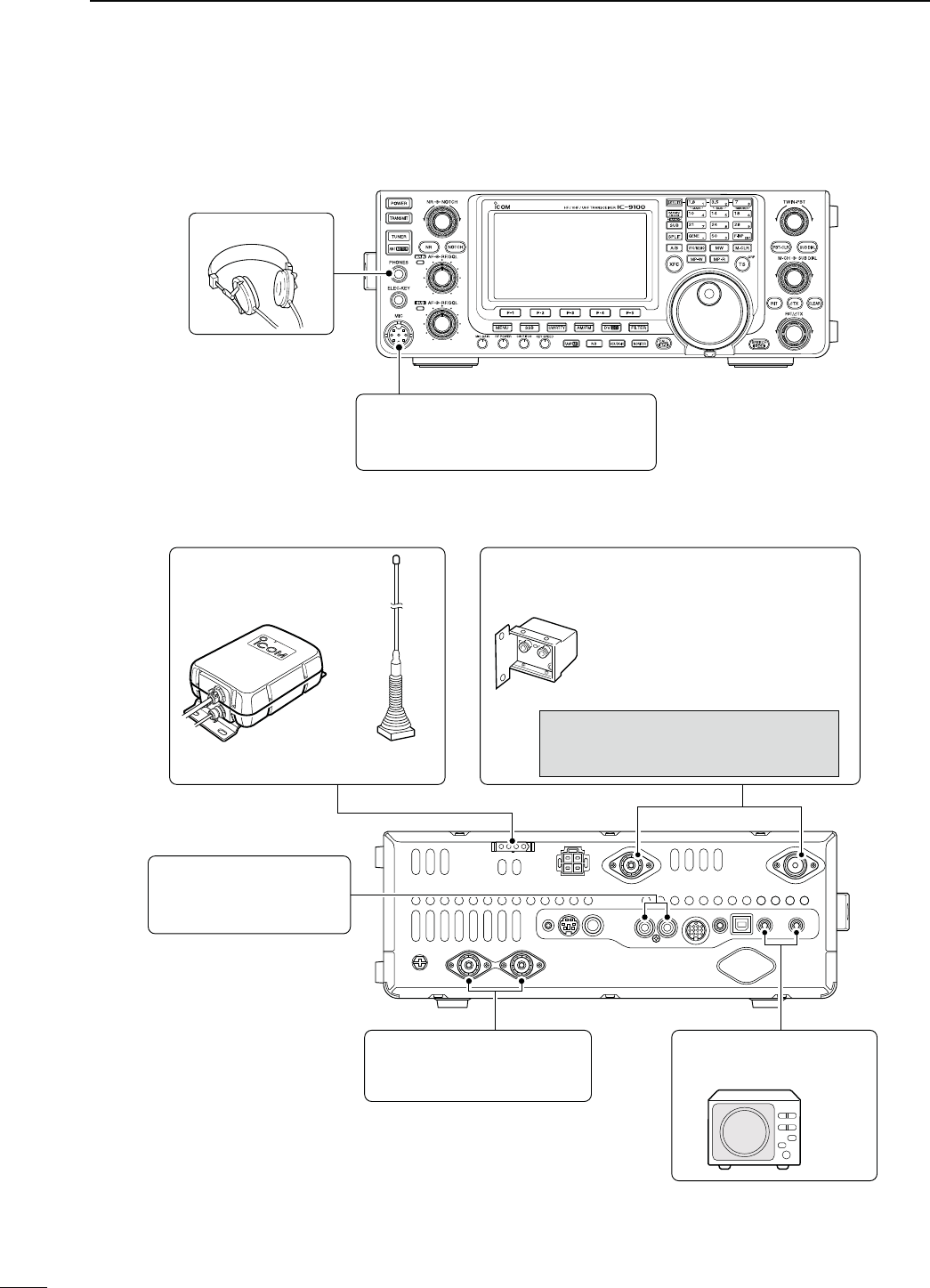
D2EARPANEL
25
2INSTALLATION AND CONNECTIONS
N!DVANCEDCONNECTIONS
D&RONTPANEL
HEADPHONES
MIC
The AFSK modulation signal can also
be input to [MIC]. (p. 171)
AH-4 (option)
(p. 29)
AH-2b (option)
or long wire
with
PREAMP (p. 71)
(144 MHz and 430 MHz)
144 MHz : AG-25 (option)
430 MHz : AG-35 (option)
External all-weather, mast-mounted
preamplifiers are available.
CAUTION: NEVER connect a power or
SWR meter, or other device between
the transceiver and preamplifier.
;!,#=;3%.$= (p. 29)
Used for connecting a
non-Icom linear amplifier.
;!.4=;!.4= (pp. 28, 29)
Connect a linear amplifier,
antenna selector, etc.
EXTERNAL SPEAKER
(MAIN/SUB)
SP-23
(option)
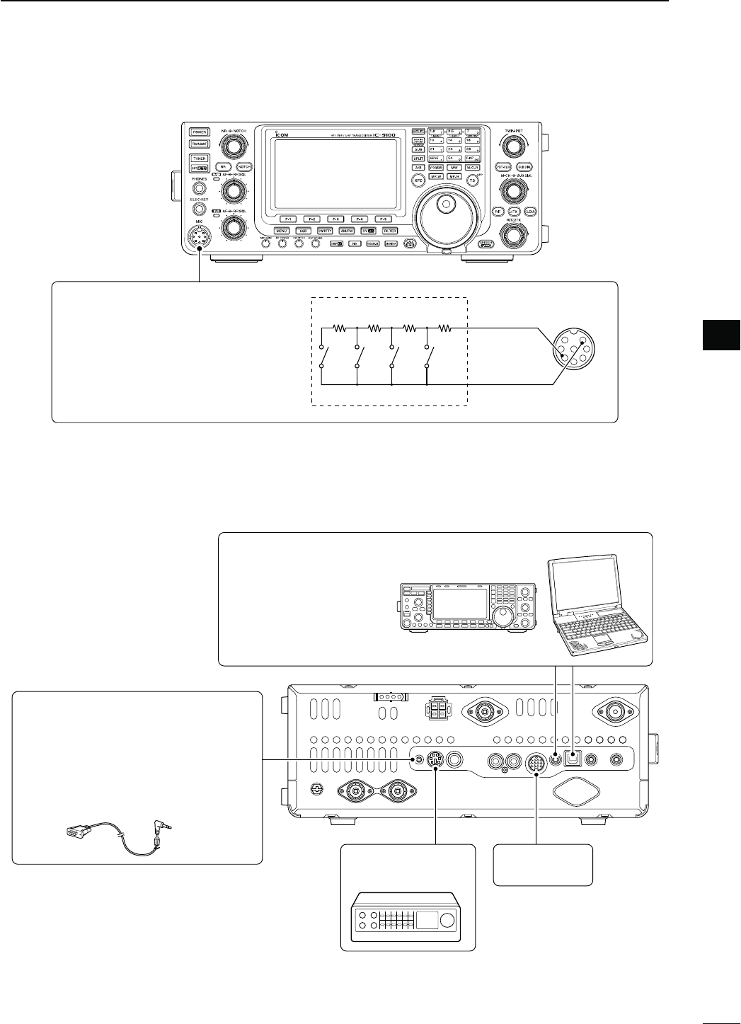
26
2
INSTALLATION AND CONNECTIONS
2
N%XTERNALKEYPADCONNECTIONS
To pin e
To pin u
1.5 kø
±5%
1.5 kø
±5%
2.2 kø
±5%
4.7 kø
±5%
S1
(M1)
S2
(M2)
S3
(M3)
S4
(M4)
EXTERNAL KEYPAD
1
2
345
6
7
8
(Front view)
[MIC]
EXTERNAL KEYPAD
Connect an external keypad for keyer
memory control.
When using a external keypad, select
h+%9%23%.$vINTHEh%XTERNAL+EY-
pad” item of the Set mode. (p. 167)
N/PTIONALANDTHEEXTERNALUNITSCONNECTIONS
DATA1 JACK (pp. 117, 121)
Connect the optional OPC-1529R for
low speed data communication using a
PC and the transceiver, or
for the GPS
receiver connection
.
A third-party serial data communication
software is required.
DATA2 SOCKET
(pp. 14, 171)
ACC SOCKET
(pp. 13, 171)
Used for computer control
and transceive operation.
The optional CT-17 is re-
quired when connecting a
PC to [REMOTE].
REMOTE JACK,53"#/..%#4/2 (p. 183)
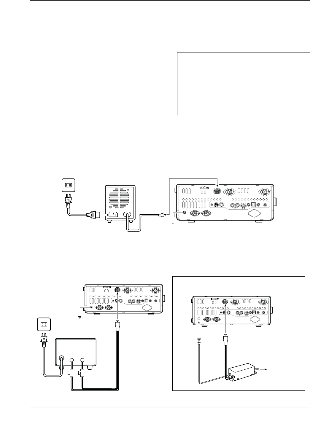
N0OWERSUPPLYCONNECTIONS
When operating the transceiver with AC power, use a
power supply with 13.8 V DC output and a capacity of
at least 24 Amperes.
Refer to the diagrams below.
CAUTION: Before connecting the DC power
cable, check the following important items.
Make sure:
s4HE;0/7%2=SWITCHIS/&&
s/UTPUTVOLTAGEOFTHEPOWERSOURCEISTO6
when you use a non-Icom power supply.
s$#POWERCABLEPOLARITYISCORRECT
Red : Positive + terminal
Black : Negative _ terminal
27
2INSTALLATION AND CONNECTIONS
Transceiver
Ground
PS-126
AC cable
AC outlet To [DC 13.8V]
+_
DC power cable
D#ONNECTINGTHE03$#0/7%23500,9
D#ONNECTINGANON)COM$#0/7%23500,9
N#ONNECTINGA$#POWERSUPPLY
Supplied DC power cable
AC cable
AC outlet
Transceiver
To [GND]
A DC power supply
6
at least 24 A
Red Black
To [DC 13.8V]
To [DC 13.8V]
For European versions
Transceiver
Ground
Connect to
power supply
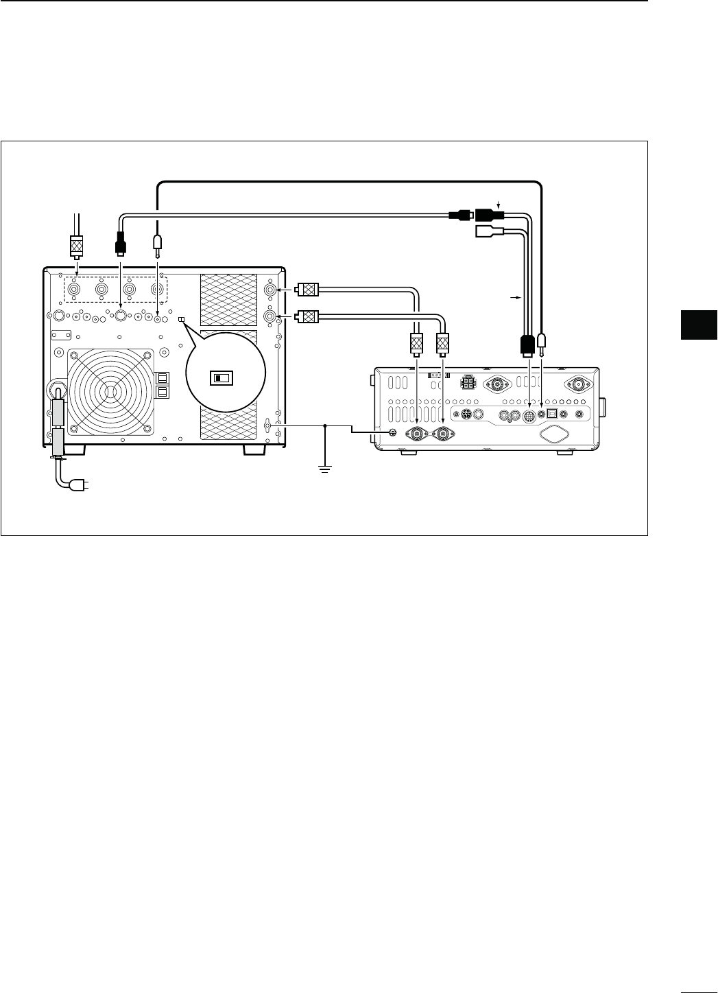
28
2
INSTALLATION AND CONNECTIONS
2
N,INEARAMPLIlERCONNECTIONS
D#ONNECTINGTHE)#0707%52/
EXCITER
11&2
Remote control cable (supplied with the IC-PW1/PW1EURO)
ACC cable (supplied with the IC-PW1/PW1EURO)
To an
antenna [ACC1]
[REMOTE][ANT]
IC-PW1/EURO
AC outlet
(Non-European versions: 100–120/200–240 V
European version : 230 V)
[INPUT1]
7-pin side
[REMOTE]
Coaxial cable
(supplied with the IC-PW1/
PW1EURO)
[ANT2]
Transceiver
[ACC]
[GND]
Ground
[ANT1]
[INPUT2]
*Purchase separately, and connect
to [INPUT2], if necessary.
[GND]
OPC-599
Coaxial cable*
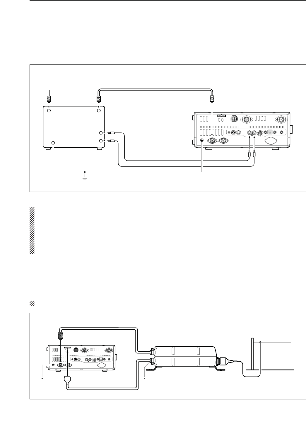
29
2INSTALLATION AND CONNECTIONS
N Linear amplifier connections (Continued)
D#ONNECTINGANON)COMLINEARAMPLIlER
R WARNING!
s3ETTHETRANSCEIVEROUTPUTPOWERANDLINEARAMPLIlER!,#OUTPUTLEVELAFTERREFERRINGTOTHELINEARAMPLIlERIN-
struction manual.
s4HE!,#INPUTLEVELMUSTBEINTHERANGE6TOn64HETRANSCEIVERDOESNOTACCEPTAPOSITIVEVOLTAGE.ON
matched ALC and RF power settings could overheat or damage the linear amplifier.
s4HE)#3%.$TERMINAL!##CONNECTORPINISRATEDAT6!$#)FTHISVALUEISEXCEEDEDALARGER
external relay must be used.
50 ø coaxial cable
To an
antenna
Non-Icom linear
amplifier
RF OUTPUT
Transceiver
[GND] [ALC]
GND
Ground
[ANT1]
N%XTERNALANTENNATUNERCONNECTION
D#ONNECTINGTHE!(
The AH-4 must be connected to [ANT1].
Transceiver
Control cable
Ground Ground
[ANT1] AH-4
Long wire or optional AH-2b
[TUNER]
Coaxial cable (from the AH-4)
ALC
SEND
[SEND]
RF INPUT
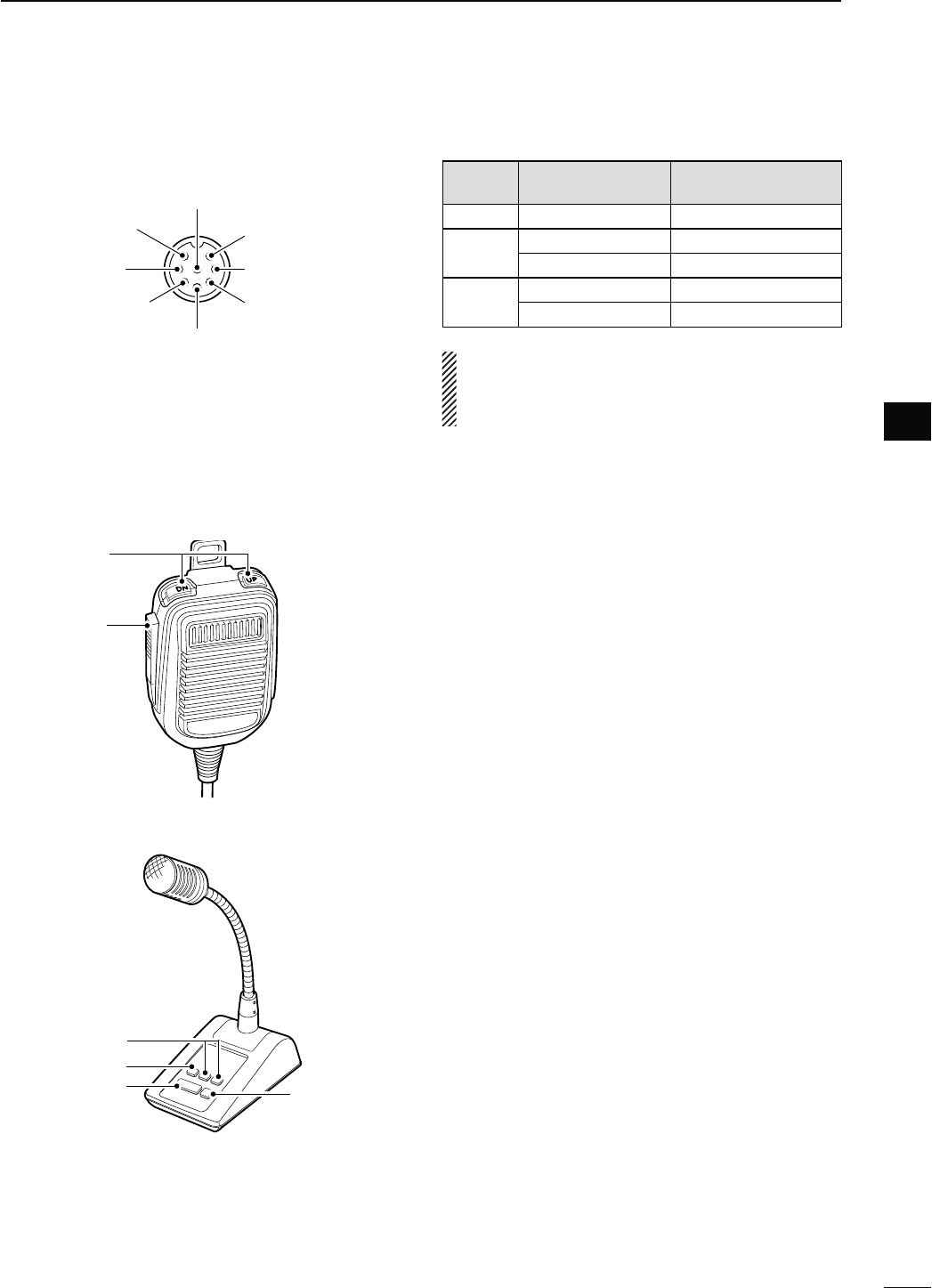
30
2
INSTALLATION AND CONNECTIONS
2
N-ICROPHONECONNECTORINFORMATION
(Front panel view)
y GND (PTT ground)
t PTT
r Main band’s squelch switch
q Microphone input
w +8 V DC output
e Frequency up/down
i Main band’s AF output
(varies with [AF])
GND
(Microphone ground)
u
[MIC]
0IN.O FUNCTION DESCRIPTION
w+8 V DC output Max. 10 mA
eFrequency up Ground
Frequency down Ground through 470 ˘
rSquelch open “Low” level
Squelch closed “High” level
CAUTION: DO NOT short pin 2 to ground as this
can damage the internal 8 V regulator. DC voltage
is applied to pin 1 for microphone operation. Use
caution when using a non-Icom microphone.
N-ICROPHONES
DHM-36
q
w
D SM-50 (Option)
q
w
r
e
qUP/DOWN SWITCHES [UP]/[DN]
Push to change the frequency or memory channel.
s7HILEHOLDINGDOWNTHEFREQUENCYORMEMORYCHANNEL
number continuously increases or decreases.
s7HILEINTHESPLITFREQUENCYMODEANDHOLDINGDOWN
[XFC], push to change the transmit frequency.
s4HE;50=;$.=SWITCHCANBEUSEDASAKEYPADDLEIF
the “MIC Up/Down Keyer” item setting is “ON” in the
Keyer Set mode. In such case, the frequency and mem-
ory channel cannot be changed using the [UP]/[DN]
switches. (p. 55)
s9OUCANSETTHEDOTDASHPOLARITYOFTHE;50=;$.=SWITCH
in the “Paddle Polarity” item of the Keyer Set mode.
When “Normal” is selected, [UP] sends a dash, and
[DN] sends a dot. (p. 55)
wPTT SWITCH
(OLDDOWNTOTRANSMITRELEASETORECEIVE
ePTT LOCK SWITCH (available on only the SM-50)
Push to toggle between transmit and receive.
rLOW CUT SWITCH (available on only the SM-50)
Push to cut out the low frequency components of
input voice signals.
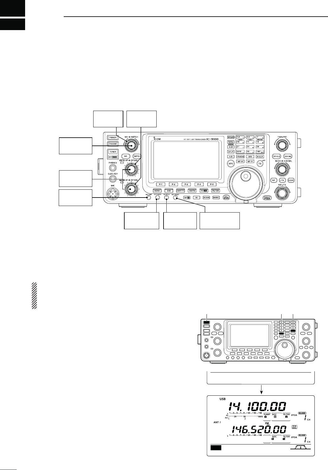
[RF/SQL]
: 12 o’clock
[MIC GAIN]
: 12 o’clock
[NR]
: Max. CCW
[CW PITCH]
: 12 o’clock
[NOTCH]
: 12 o’clock
[RF POWER]
: Max. CW
;+%930%%$=
: 10–12 o’clock
[AF]
: Max. CCW
N"EFORElRSTAPPLYINGPOWER
Before turning ON your transceiver for the first time,
make sure all connections required for your system
are complete by reviewing them in Section 2 of this
manual.
After all connections have been made, set controls
and switches as shown in the illustration below.
CW : Max. clockwise
CCW : Max. counterclockwise
3
31
"!3)#/0%2!4)/.
[POWER] [F-INP ENT] [VFO/MEMO]
N4URNING/.0ARTIALRESETTING
First time to Power ON:
Reset the transceiver using the following procedure.
A partial resetting CLEARS the operating parame-
ters to their default values (VFO frequency, VFO
settings, menu group’s contents) without clearing
certain data. See page 181 for details.
qMake sure the transceiver’s power is OFF.
w
While holding down both [F-INP ENT] and [VFO/
MEMO], push [POWER] to turn ON the transceiver.
s$URING STARTUP THE TRANSCEIVER DISPLAYSh0!24)!,
RESET,” then its initial VFO frequencies when resetting
is complete.
s)FYOUOPERATETHETRANSCEIVERBEFOREh0!24)!,2%3%4v
disappears, the resetting will be cancelled.
e Change the Set mode settings to suit your operat-
ing needs. (p. 161)
Normal Power ON:
Push [POWER] to turn ON the transceiver.
Power OFF:
Hold down [POWER] for 1 second to turn OFF the
transceiver.
AGC DUP COMP TBW SCP
M1
PARTIAL RESET
Initial VFO display
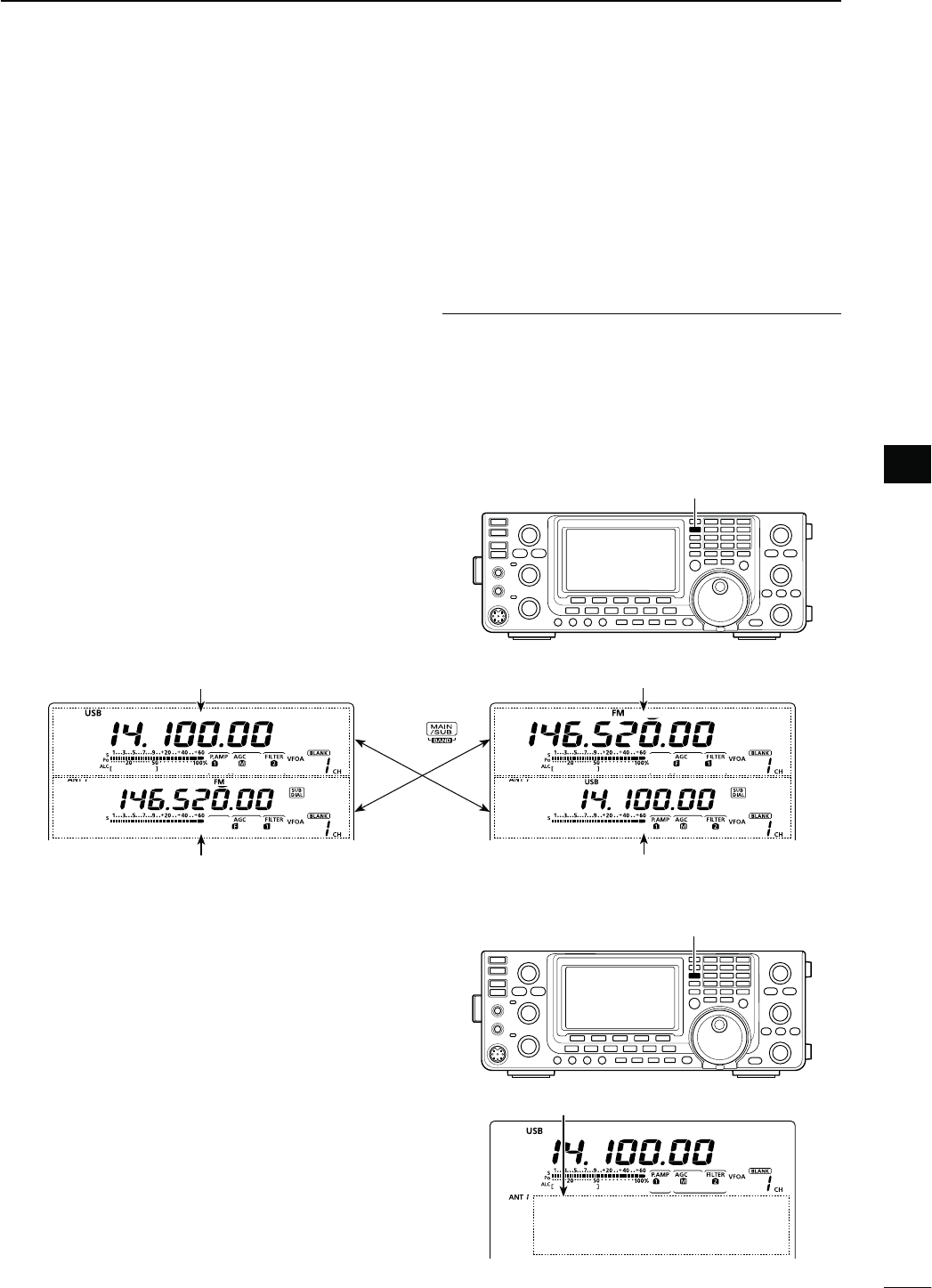
32
3
BASIC OPERATION
3
32
3
N-!).AND35""ANDS
The IC-9100 can operate on the HF/50 MHz, 144 MHz,
430 MHz and 1200 MHz* frequency bands. These fre-
quency bands can be assigned to the MAIN and SUB
Bands for operating convenience.
The MAIN and SUB Bands cannot simultaneously oper-
ate on frequency bands within the HF/50 MHz band. For
example, if the MAIN Band is set to operate on any fre-
quency within the HF/50MHz band, the SUB Band can
simultaneously receive on only the 144 MHz, 430 MHz
and 1200 MHz* frequency bands, or visa versa.
*The optional UX-9100 is required for the 1200 MHz fre-
quency band operation.
Both MAIN and SUB Bands have independent features.
MAIN Band : Used for both transmitting and receiving.
The MAIN Band area is in the upper half
of the LCD display.
SUB Band :
Used for only receiving. The SUB Band
area is in the lower half of the LCD display.
!BOUTTRANSMITTING
9OUCANTRANSMITONONLYTHE-!)."ANDNOTONTHE
SUB Band. However, while operating in the Satellite
mode, you can transmit on the SUB Band.
D-!).35""ANDSELECTION
The LCD display shows both the MAIN and SUB Band
frequencies. Both Bands can receive signals simulta-
neously, but not on the same frequency band. Set the
frequency band you want to transmit or be called on,
as the MAIN Band.
±Push [MAIN/SUB] to toggle the MAIN and SUB
Bands.
SUB Band display (146.520 MHz FM)
MAIN Band display (14.100 MHz USB)
Push
SUB Band display (14.100 MHz USB)
MAIN Band display (146.520 MHz FM)
[MAIN/SUB]
D35""ANDDISPLAY
The SUB Band display can be turned OFF to simplify
operation.
±Hold down [SUB] for 1 second to turn the SUB Band
display ON or OFF.
s.OTHINGISDISPLAYEDONTHE35""ANDDISPLAYWHENITIS
turned OFF.
[SUB]
SUB Band display
When the SUB Band display is OFF
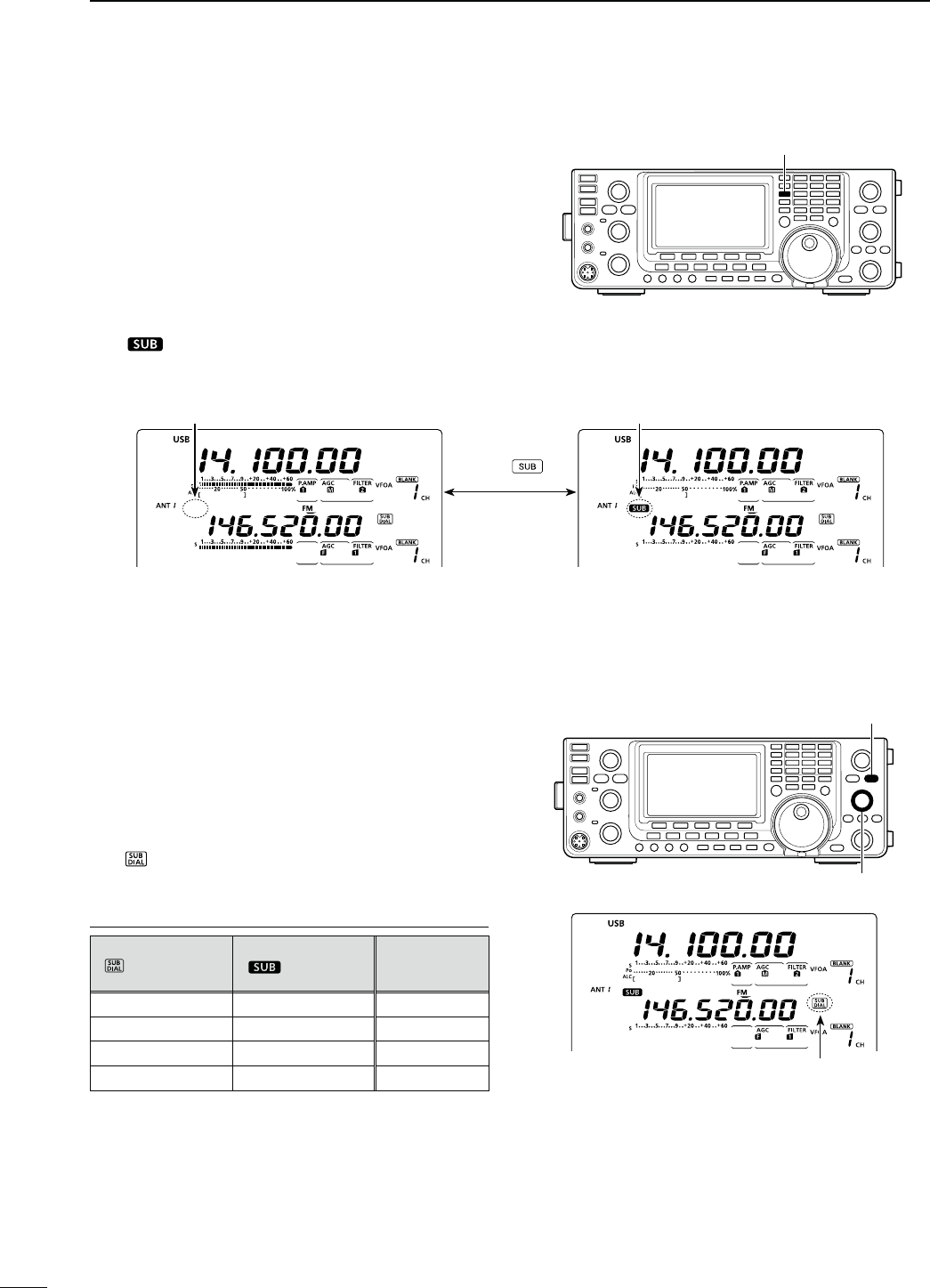
33
3BASIC OPERATION
D4HE35"$IALFUNCTION
The [SUB DIAL] control’s tuning Band and frequency
steps differ, depending on the combination of the SUB
Dial function and SUB Band setting mode, and the sta-
tus of the quick tuning function.
±Push [SUB DIAL] to turn the SUB Dial function ON
or OFF.
sh ” appears when the function is ON.
!BOUTTHE4UNED"ANDWITHTHE;35"$)!,=CONTROL
35"$IALFUNCTION
(“ ” appears when
ON is selected.)
35""ANDSETTING
(“ ”appears when
ON is selected.)
4UNED"AND
ON ON SUB Band*
ON OFF SUB Band*
OFF ON SUB Band†
OFF OFF MAIN Band†
* The frequency changes in 1 Hz, 10 Hz, 1 MHz or pre-set
kHz steps, depending on the quick tuning step setting. (p.
38)
† The frequency changes in the programmed kHz steps,
even if the quick tuning is OFF.
[SUB DIAL]
[SUB DIAL] control
Appears when the SUB Dial function is ON.
D35""ANDSETTINGMODEOPERATION
Normally, tuning, operating mode selection, memory
channel selection and programming, are made for the
MAIN Band.
When the SUB Band setting mode is ON, the settings
and selections are for only the SUB Band.
s9OUCANNOTTRANSMITONTHE35""AND
s9OUCANNOTMAKE-AIN"ANDSETTINGS
±Push [SUB] to turn the SUB Band setting mode ON
or OFF.
sh” appears when the SUB Band setting mode is
ON.
[SUB]
Appears
The SUB Band setting mode is OFF.
Push
The SUB Band setting mode is ON.
Disappears
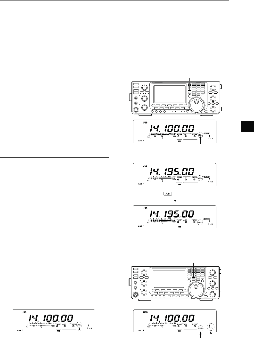
34
3
BASIC OPERATION
3
N6&/DESCRIPTION
4HE)#HASTWO6&/Sh!vANDh"vFOREACH-!).
and SUB Bands, and are convenient for quickly select-
ing two frequenciesORSPLITFREQUENCYOPERATION9OU
can use either VFO to call up a frequency and operat-
ing mode.
VFO is an abbreviation of Variable Frequency Oscil-
lator.
D 3ELECTINGTHE6&/!"
±Push [A/B] to switch between the VFO A and
VFO B.
sh6&/!vORh6&/"vAPPEARSWHENTHE6&/ISSELECTED
D 6&/EQUALIZATION
±Hold down [A/B] for 1 second to equalize the data
in both VFOs.
sBEEPSSOUNDWHENTHEEQUALIZATIONISCOMPLETE
CONVENIENT!
5SETWO6&/SASQUICKMEMORIES
When you find a new station, but wish to continue
searching, the dual VFO system can be used for quick
memory storage.
qHold down [A/B] for 1 second to store the displayed
contents into the undisplayed VFO.
w Continue searching for stations.
ePush [A/B] to show the stored contents on the un-
displayed VFO.
rTo continue searching for stations, push [A/B] again
to show the displayed VFO.
N3ELECTING6&/MEMORYMODE
±Push [VFO/MEMO] to switch between the VFO
and memory modes.
sh6&/ !vORh6&/ "vAPPEARSWHENIN THE 6&/MODE
or “MEMO” and the selected memory channel number
appear when in the memory mode.
s(OLDING DOWN ;6&/-%-/= FOR SECOND COPIES THE
contents of the selected memory channel into the dis-
played VFO. (p. 142)
Memory icon
The selected VFO icon
[A/B]
The selected VFO icon
q Hold down
e Push
Displayed VFO
Undisplayed VFO
[VFO/MEMO]
Memory channel number
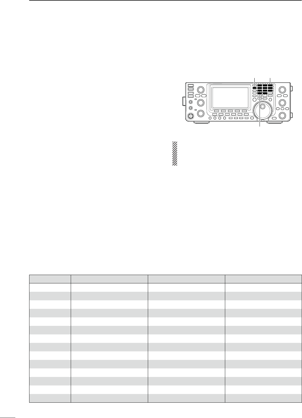
35
3BASIC OPERATION
"!.$ REGISTER 1 REGISTER 2 REGISTER 3
1.8 MHz 1.900000 MHz CW 1.910000 MHz CW 1.915000 MHz CW
3.5 MHz 3.550000 MHz LSB 3.560000 MHz LSB 3.580000 MHz LSB
7 MHz 7.050000 MHz LSB 7.060000 MHz LSB 7.020000 MHz CW
10 MHz 10.120000 MHz CW 10.130000 MHz CW 10.140000 MHz CW
14 MHz 14.100000 MHz USB 14.200000 MHz USB 14.050000 MHz CW
18 MHz 18.100000 MHz USB 18.130000 MHz USB 18.150000 MHz USB
21 MHz 21.200000 MHz USB 21.300000 MHz USB 21.050000 MHz CW
24 MHz 24.950000 MHz USB 24.980000 MHz USB 24.900000 MHz CW
28 MHz 28.500000 MHz USB 29.500000 MHz USB 28.100000 MHz CW
50 MHz 50.100000 MHz USB 50.200000 MHz USB 51.000000 MHz FM
144 MHz 146.520000 MHz FM 145.100000 MHz FM 145.200000 MHz FM
430 MHz 446.000000 MHz FM 440.100000 MHz FM 440.200000 MHz FM
1200 MHz*11294.500000 MHz FM 1295.100000 MHz FM 1294.200000 MHz FM
General*215.000000 MHz USB 15.100000 MHz USB 15.200000 MHz USB
*1 The optional UX-9100 is required for the 1200 MHz frequency band operation.
*2;'%.%s=SELECTSTHEGENERALCOVERAGEBAND
D5SINGTHEBANDSTACKINGREGISTERS
The triple band stacking register provides 3 memo-
ries for each band key to store frequencies and oper-
ating modes.
This function is convenient when you operate 3 operat-
ing modes on one frequency band.
For example, one register can be used for a CW fre-
quency, another for an SSB frequency and the other
ONEFORAN2449FREQUENCY
)FABANDKEYOR;'%.%s=ISPUSHEDONCETHELAST
used frequency and operating mode are called up.
When the key is pushed again, another stored fre-
quency and operating mode are called up.
* If you are using a frequency band other than HF/50 MHz,
you can call up the HF/50 MHz frequency band by pushing
THEBANDKEYS;=TO;=OR;'%.%s=
See the table below for a list of the available frequency
bands and their default frequency and mode settings.
N3ELECTINGAFREQUENCYBAND
The frequency band you want to use can be selected
in the MAIN and SUB Bands.
Before changing the frequency band on the SUB Band,
push [SUB] to turn ON the SUB Band setting mode.
In addition to the HF/50 MHz, 144 MHz and 430 MHz
frequency bands, the IC-9100 can operate on the
1200 MHz frequency band*1.
qHold down [BAND](MAIN/SUB) for 1 second sev-
eral times until the desired frequency of the bands
that are stored in the MAIN or SUB Band, which-
ever you selected.
w
To call up the previously selected frequency and op-
ERATINGMODEPUSHABANDKEYOR;'%.%s=IFTHE
HF/50 MHz
frequency band
was selected in step q,
ORPUSH;'%.%s=IFTHE
144 MHz, 430 MHz or 1200
MHz frequency band*1
was selected.
[BAND](MAIN/SUB) Band keys
NOTE: The same frequency band cannot be simul-
taneously selected in both MAIN and SUB Bands.
The frequency band, selected in either the MAIN or
SUB Band, cannot be selected on the other Band.
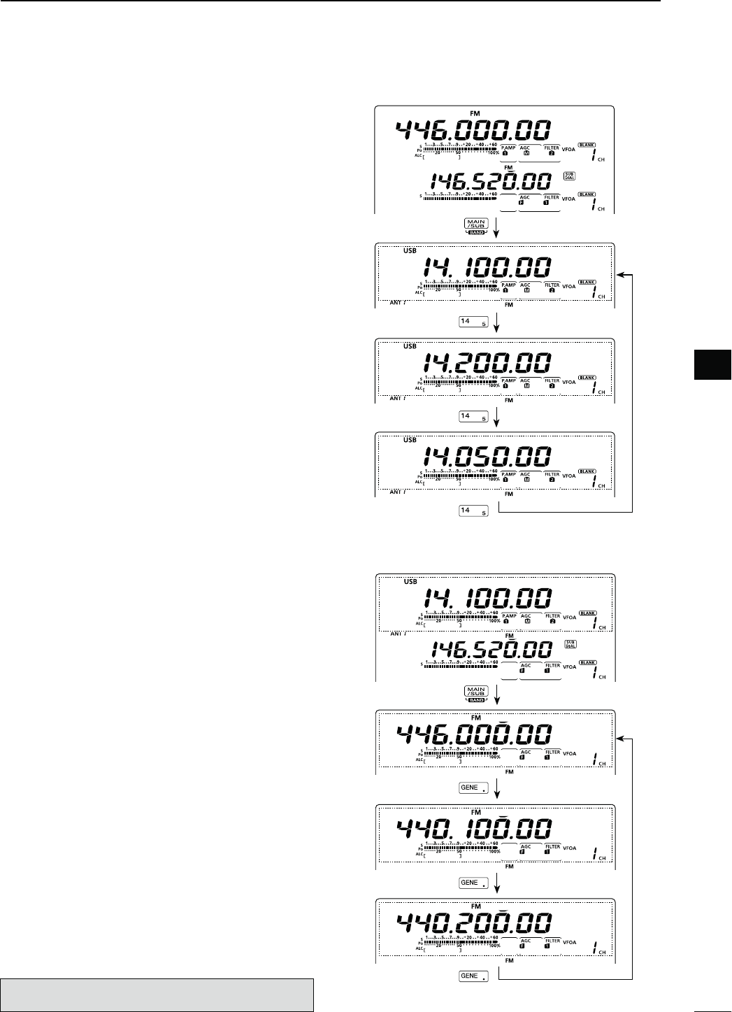
36
3
BASIC OPERATION
3
&REQUENCYBAND(&-(Z
q Hold down [BAND](MAIN/SUB) for 1 second sev-
eral times until a HF/50 MHz frequency band is dis-
played.
w0USHABANDKEY;=TO;=OR;'%.%s=
s4HEPREVIOUSLYSELECTEDFREQUENCYANDOPERATINGMODE
are called up as the first band stacking register of that
frequency band.
e Select a frequency and an operating mode, and
then push the band key.
s4HESELECTEDFREQUENCYANDMODEAREMEMORIZEDAS
that frequency band’s first band stacking register.
r Select another frequency and operating mode, and
then push the band key.
s4HESELECTEDFREQUENCYANDMODEAREMEMORIZEDAS
that frequency band’s second band stacking register.
t Select another frequency and operating mode, and
then push the band key.
s4HESELECTEDFREQUENCYANDMODEAREMEMORIZEDAS
that frequency band’s third band stacking register.
y The first band stacking register set in step e, is
called up.
s7HENTHEFREQUENCYBANDKEYISPUSHEDTHEMEMO-
rized triple band stacking registers are sequentially
called up.
&REQUENCYBAND-(Z
q Hold down [BAND](MAIN/SUB) for 1 second sev-
eral times until a 144 MHz, 430 MHz or 1200 MHz
frequency band is displayed.
s4HEPREVIOUSLYSELECTEDFREQUENCYANDANOPERATING
mode are called up as the first band stacking register of
that frequency band.
w Select a frequency and an operating mode, and
THENPUSH;'%.%s=
s4HESELECTEDFREQUENCYANDMODEAREMEMORIZEDAS
that frequency band’s first band stacking register.
e Select another frequency and operating mode, and
THENPUSH;'%.%s=
s4HESELECTEDFREQUENCYANDMODEAREMEMORIZEDAS
that frequency band’s second band stacking register.
r Select another frequency and operating mode, and
THENPUSH;'%.%s=
s4HESELECTEDFREQUENCYANDMODEAREMEMORIZEDAS
that frequency band’s third band stacking register.
t The first band stacking register set in step w, is
called up.
s7HEN;'%.%s=ISPUSHEDTHEMEMORISEDTRIPLEBAND
stacking registers are sequentially called up.
The optional UX-9100 is required for 1200 MHz frequency
band operation.
Hold down
Push
Push
Push
Hold down
;%XAMPLE= 14 MHz frequency band
;%XAMPLE= 430 MHz frequency band
Push
Push
Push
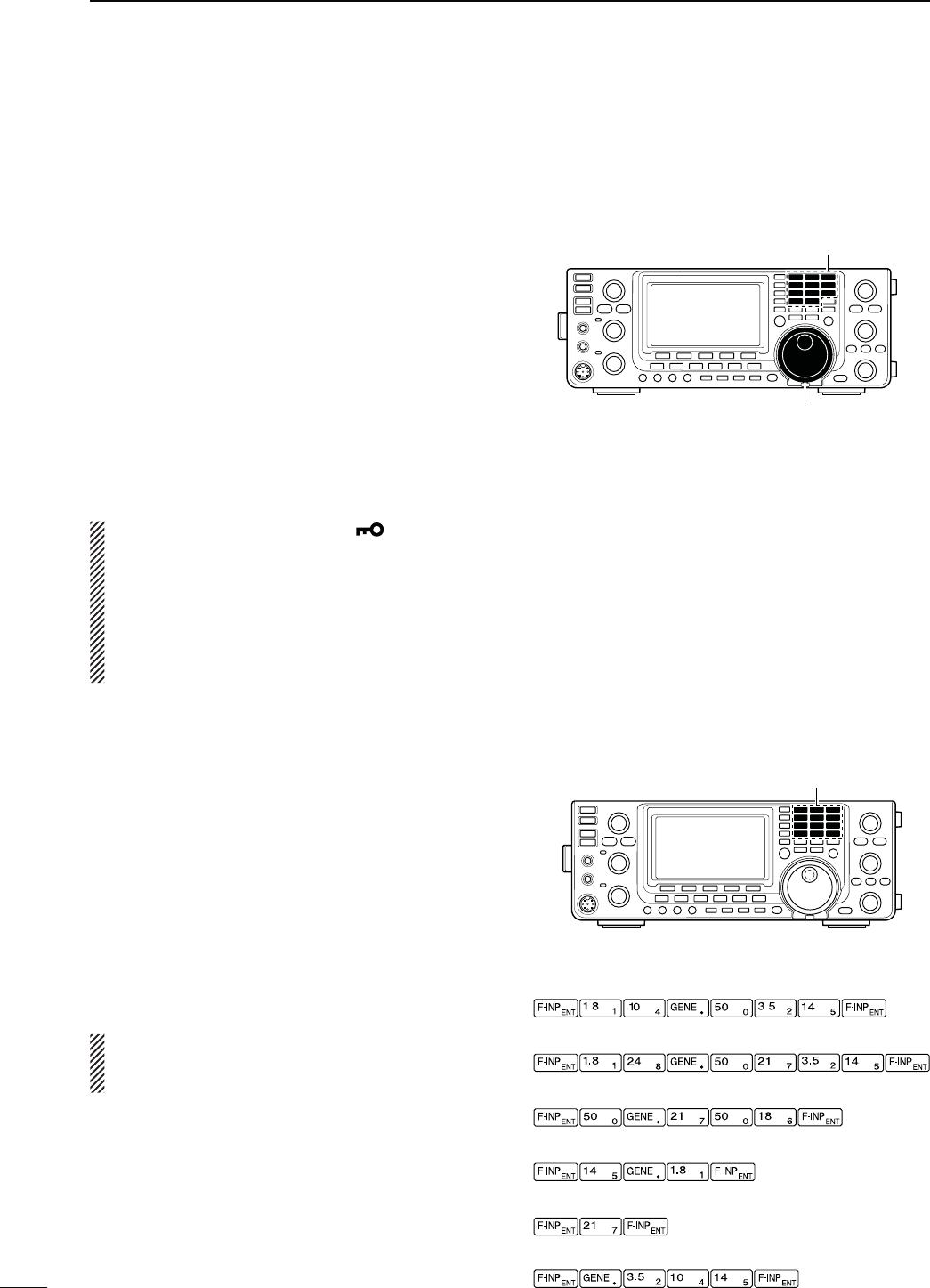
37
3BASIC OPERATION
N&REQUENCYSETTING
9OUCANSELECTTHETRANSCEIVERSFREQUENCYBYUSING
[MAIN DIAL], or you can enter it using the keypad.
D4UNINGWITH;-!).$)!,=
q Select the desired frequency band.
s(OLDDOWN;"!.$=-!).35"FORSECONDSEVERAL
times until the desired frequency band is displayed.
s0USHTHEDESIREDBANDKEYONTHEKEYPADOR;'%.%s=
1–3 times.
3 different frequencies on each frequency band can be
selected with the band key. (See previous page “Using
the band stacking registers.”)
s4HEDEFAULTTUNINGSTEPDIFFERSDEPENDINGONTHEOPERAT-
ing mode.
33"#72449(Z
AM : 1 kHz (“Z” is displayed)
FM/DV : 10 kHz (“Z” is displayed)
w Rotate [MAIN DIAL] to set the desired frequency.
If the Dial Lock function is ON, “ ” is displayed,
and [MAIN DIAL] does not function.
In this case, hold down [SPEECH/LOCK] for 1 sec-
ond to turn OFF the lock function. (p. 77)
When “LOCK/SPEECH” is selected in the
“[SPEECH/LOCK] SW” item of the Set mode, push-
ing [SPEECH/LOCK] turns OFF the lock function.
(see p. 164 for details)
D$IRECTFREQUENCYENTRYWITHTHEKEYPAD
The transceiver has a keypad for direct frequency
entry, as described below.
q Push [F-INP ENT] to enter frequencies with the
keypad.
s!LLFREQUENCYDIGITSDISAPPEAR
w Push the numeric keys to input the desired fre-
quency.
s0USH;'%.%s=TOINPUTAhvDECIMALPOINTBETWEENTHE
1 MHz digits and 100 kHz digits.
e Push [F-INP ENT] to set the input frequency.
s4OCANCELTHEINPUTPUSH;%8)43%4=BEFOREPUSHING
[F-INP ENT].
NOTE: The frequency band, selected in either the
MAIN or SUB Band, cannot be selected on the other
Band.
Keypad
[EXAMPLE]
-(Z
-(Z
K(Z
-(Z
-(Z
-(Z¶-(Z
Band keys
[MAIN DIAL]
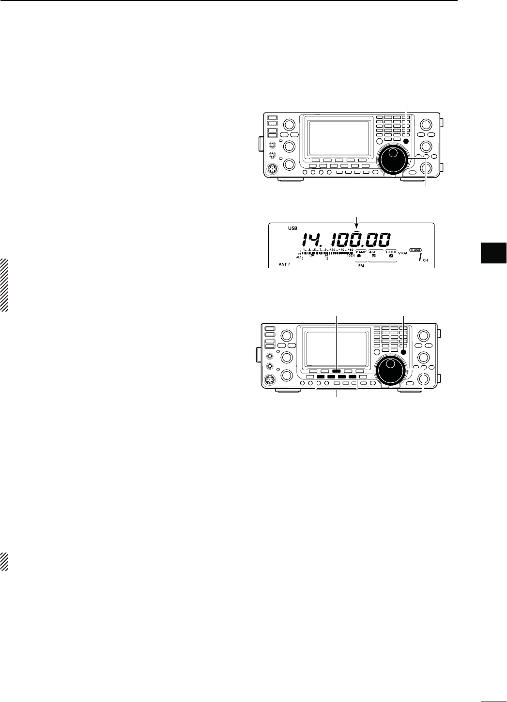
38
3
BASIC OPERATION
3
D1UICK4UNINGFUNCTION
The operating frequency can be changed in 1 kHz or
1 MHz steps for quick tuning.
Select the desired tuning step in each operating fre-
quency band and mode.
q Push [TS] to select the 1 kHz or 1 MHz Quick Tun-
ing function step, or turn it OFF.
s7HILETHEQUICKTUNINGICONhZ,” is displayed above the
1 kHz or 1 MHz digit, the frequency will be changed in
1 kHz or 1 MHz steps.
s7HENTHEFUNCTIONIS/&&THEFREQUENCYWILLBECHANGED
in 10 Hz steps.
w Rotate [MAIN DIAL] to change the frequency in the
selected steps.
NOTE:
s4OTURN/&&THE1UICK4UNINGFUNCTIONPUSH;43=
again. (“Z” disappears)
s7HENTHE1UICK4UNINGFUNCTIONIS/&&THEFRE-
quency will be changed in 10 Hz steps.
D3ELECTINGhK(ZvSTEP
When the 1 kHz quick tuning is selected, the frequency
can be changed in the selected “kHz” steps.
The MAIN and SUB Bands use the common “kHz” tun-
INGSTEP9OUCANSELECTITINBOTH"ANDS
q Push [TS] to turn ON the Quick Tuning function.
shZ” appears.
w Hold down [TS] for 1 second to display the “TS”
screen to select the quick tuning step.
eSelect the desired operating mode.
r
Rotate [MAIN DIAL] to select the desired “kHz” step.
sANDK(ZARE
selectable.
s(OLDDOWN;&=FORSECONDTORETURNTOTHEDEFAULTSET-
ting, if desired.
t Repeat steps e and r to select quick tuning steps
for other modes.
yPush [TS] to exit the “TS” screen.
NOTE: To display the “TS” screen, the Quick Tuning
function must be turned ON first.
[TS]
[MAIN DIAL]
Appears
[TS][F-3]
Mode selection [MAIN DIAL]
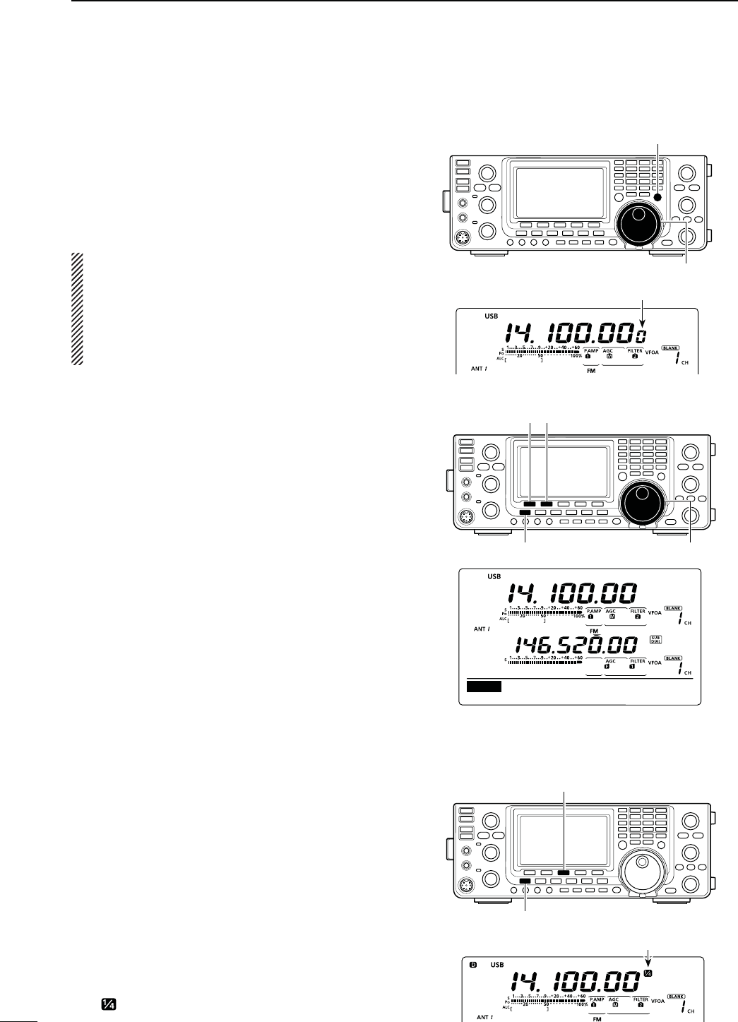
39
3BASIC OPERATION
N Frequency setting (Continued)
D3ELECTING(ZSTEP
9OUCANCHANGETHEFREQUENCYIN(ZSTEPSFORFINE
tuning.
q Push [TS] to turn OFF the Quick Tuning function.
w Hold down [TS] for 1 second to turn the 1 Hz tuning
step ON or OFF.
NOTE:
s7HEN2)4ANDOR∂TX are used, they also tune in
1 Hz tuning steps.
s4HEFREQUENCYCHANGESIN(ZSTEPSWHENTHE
[UP]/[DN] switches of the microphone are used
for frequency tuning (if the quick tuning function is
not selected.)
D!UTOTUNINGSTEPFUNCTION
When you rotate [MAIN DIAL] rapidly, the tuning speed
can automatically accelerate, depending on the “MAIN
DIAL Auto TS” option in the Set mode.
q Hold down [MENU] for 1 second to enter the Set
mode.
w Push [Y](F-1) or [Z](F-2) to select “MAIN DIAL
Auto TS.”
e Rotate [MAIN DIAL] to select the HIGH or LOW
tuning speed acceleration, or to turn OFF the func-
tion.
s()'(7HENTHETUNINGSTEPISSETTOK(ZOR
smaller steps, the tuning speed is approxi-
mately five times faster.
When the tuning step is set to 5 kHz or
larger steps, the tuning speed is approxi-
mately two times faster.
(default)
s,/7!PPROXIMATELYTWOTIMESFASTER
s/&& !UTOTUNINGSTEPISTURNED/&&
s(OLDDOWN;#,2=&FORSECONDTORESETTOTHEDE-
fault value.
rPush [MENU] to save, and exit the Set mode.
D1⁄4TUNINGSTEPFUNCTION
-ODE33"$#72449
The dial speed is reduced to 1⁄4 of the normal speed
when the 1⁄4 tuning function is ON, for finer tuning con-
trol.
9OUCANSETTHE1⁄4 tuning function in each operating
mode.
This function is selectable only when the quick tuning
function is turned OFF.
q Push [MENU] to display the “M1” screen (menu 1).
w Push [1⁄4](F-3) to turn the 1⁄4 tuning function ON or
OFF.
sh ” appears when the 1⁄4 tuning function is ON.
[TS]
[MAIN DIAL]
1 Hz step indication
[][]
[MAIN DIAL][MENU]
HIGH (default)
Ù
44
ÚHIGH
SET MAIN DIAL Auto TS
[1⁄4]
[MENU]
Appears
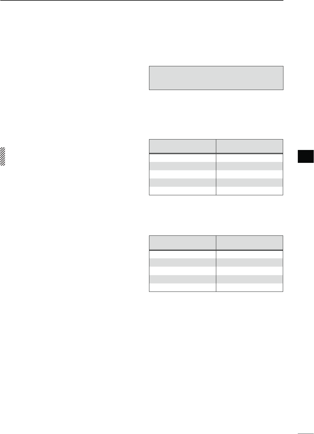
40
3
BASIC OPERATION
3
D!BOUTTHE-(ZFREQUENCYBANDOPERATIONONLY53!VERSION
Operation on the 5 MHz frequency band is allowed on
5 discrete frequencies and must adhere to the follow-
ing:
s4HE53"USB Data and CW modes
s-AXIMUMOF100 watts ERP (Effective Radiated Power)
sK(ZBANDWIDTHMAXIMUM
It is your responsibility to set all controls so that trans-
mission in this frequency band meets the stringent
conditions under which amateur operations may use
these frequencies.
NOTE: We recommend that you store these fre-
quencies, modes and filter settings into memory
channels, for easy recall.
To assist you in operating within the rules specified
by the FCC, transmission is illegal on any frequen-
cies other than the five shown in the tables below.
s&ORTHE53"AND53"$ATAMODES
The FCC specifies center frequencies on the 5 MHz
frequency band. However, the transceiver displays
carrier frequency. Therefore, tune the transceiver to
1.5 kHz below the specified FCC channel center fre-
quency.
4RANSCEIVER$ISPLAYED
&REQUENCY
&###HANNEL
#ENTER&REQUENCY
5.33050 MHz 5.33200 MHz
5.34650 MHz 5.34800 MHz
5.35700 MHz 5.35850 MHz
5.37150 MHz 5.37300 MHz
5.40350 MHz 5.40500 MHz
s&ORTHE#7MODE
The transceiver displays the center frequency. There-
fore, tune the transceiver to the specified FCC channel
frequency when you operate in these modes.
4RANSCEIVER$ISPLAYED
&REQUENCY
&###HANNEL
#ENTER&REQUENCY
5.33200 MHz 5.33200 MHz
5.34800 MHz 5.34800 MHz
5.35850 MHz 5.35850 MHz
5.37300 MHz 5.37300 MHz
5.40500 MHz 5.40500 MHz
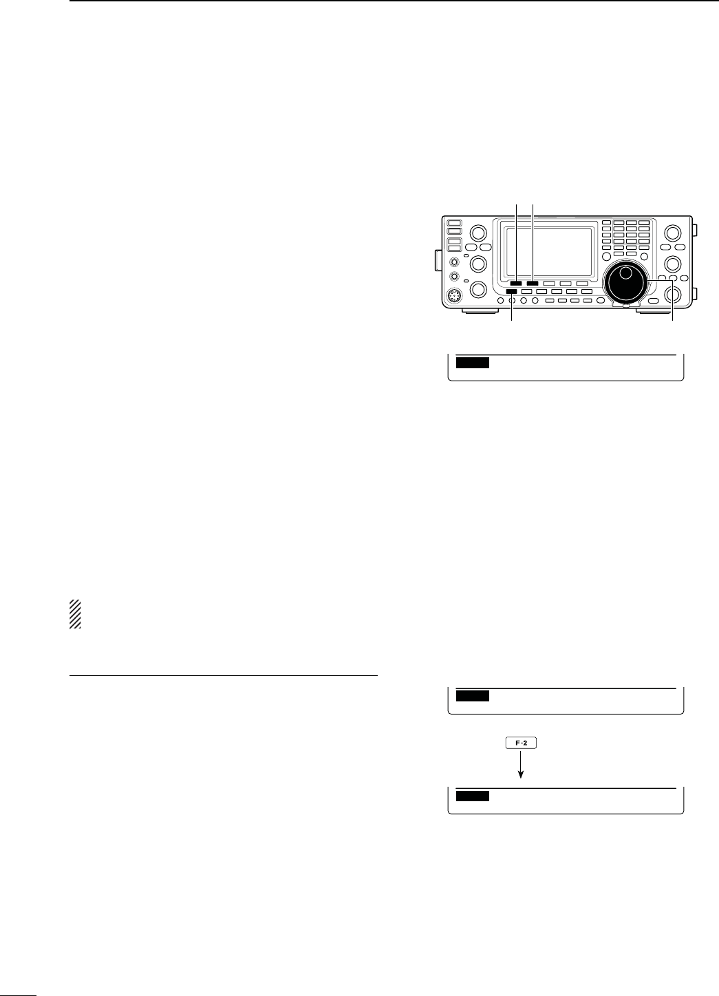
41
3BASIC OPERATION
N Frequency setting (Continued)
D"ANDEDGEWARNINGBEEP
9OUCANHEARABEEPTONEWHENYOUTUNEINTOOROUT
of an amateur band’s frequency range. A regular beep
sounds when you tune into a range, and an lower tone
error beep sounds when you tune out of a range.
q Hold down [MENU] for 1 second to enter the Set
mode.
w Push [Y](F-1) or [Z](F-2) to select “Band Edge
Beep.”
e Rotate [MAIN DIAL] to select the desired band edge
warning beep setting.
s/&& "ANDEDGEBEEPIS/&&
s/.$EFAULT 7HEN YOU TUNE INTO OR OUT OF
the default amateur band’s fre-
quency range, a beep sounds.
(default)
s/.5SER 7HEN YOU TUNE INTO OR OUT OF
a user programmed amateur
band’s frequency range, a beep
sounds.
s/.5SER487HEN YOU TUNE INTO OR OUT OF
a user programmed amateur
band’s frequency range, a beep
sounds. Also transmission is in-
hibited outside the programmed
range.
s(OLDDOWN;#,2=&FORSECONDTORESETTOTHEDE-
fault value.
rPush [MENU] to save, and exit the Set mode.
The beep output level can be set in the “Beep Level”
item of the Set mode. (p. 161)
!BOUTTHEUSERBANDEDGEFREQUENCIES
7HENh/.5SERvORh/.5SER48vISSELECTEDIN
the “Band Edge Beep” item, a total of 30 band edge
frequencies can be programmed in the “User Band
Edge” item. See the next page for details.
If “OFF” or “ON (Default)” is selected, the “User Band
Edge” item does not appear in the Set mode.
[][]
[MAIN DIAL][MENU]
ON (Default)
Ù
6
ÚON(Default)
SET Band Edge Beep
ON (User) selection
Ù
6
ÚON(User)
SET Band Edge Beep
[User Band Edge] item
Ù
7
ÚDEF EDT
SET User Band Edge
Push
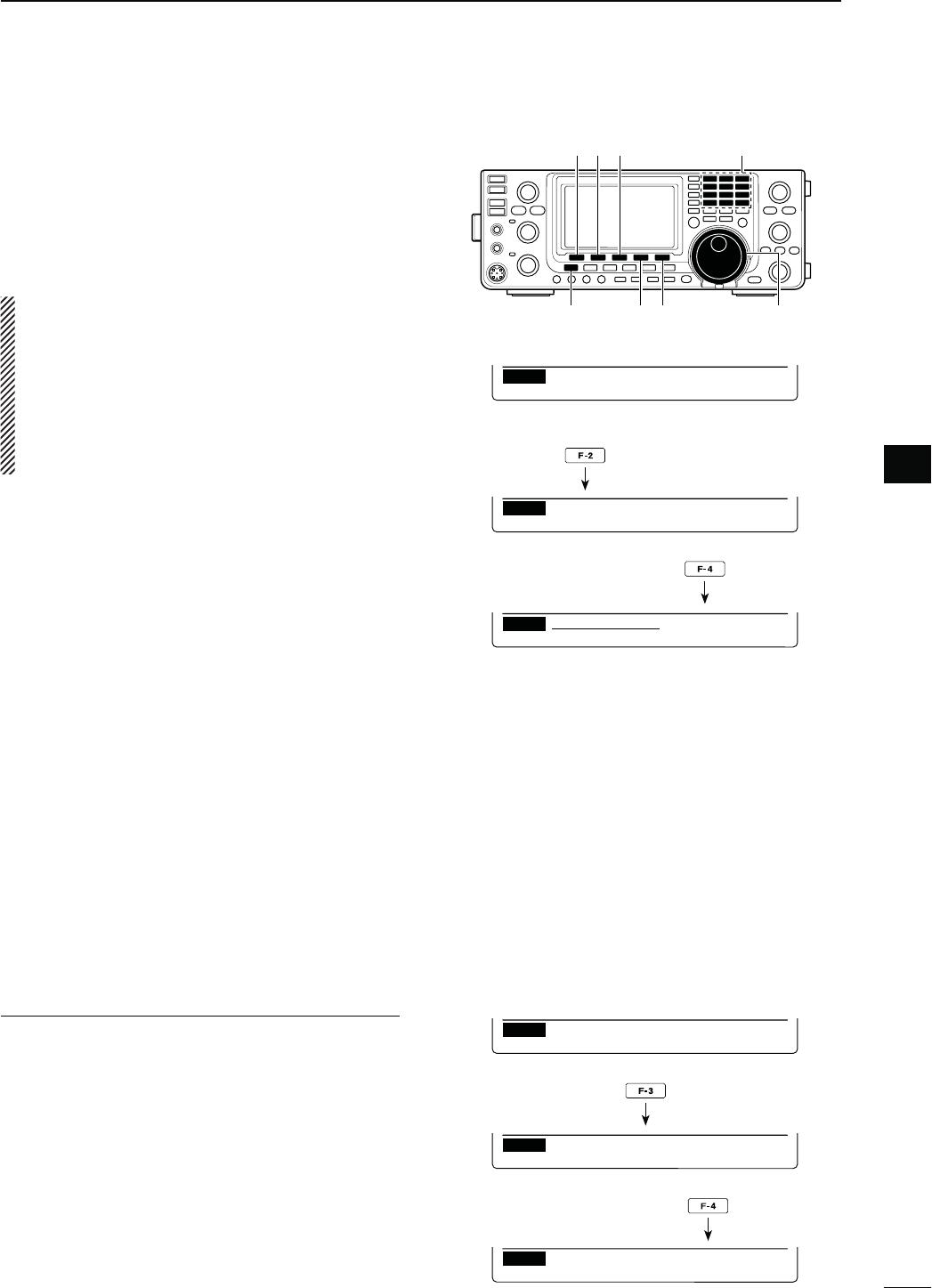
42
3
BASIC OPERATION
3
D0ROGRAMMINGTHEUSERBANDEDGE
7HENh/.5SERvORh/.5SER48vISSELECTEDIN
the “Band Edge Beep” item, the “User Band Edge”
item appears in the Set mode.
A total of 30 band edge frequencies can be pro-
grammed in the “User Band Edge” item.
NOTE:
s!LLFREQUENCYRANGESARESET TODEFAULTSOYOU
should delete or change them to add the desired
band edge frequency.
s0ROGRAMEACHCHANNELFROMLEFTTORIGHTANDEACH
frequency must be higher than the preceding fre-
quency.
s4HEFREQUENCYTHATISDUPLICATEDOROUTOFANAMA-
teur band, cannot be programmed.
q Hold down [MENU] for 1 second to enter the Set
mode.
w Push [Y](F-1) or [Z](F-2) to select “Band Edge
Beep.”
e Rotate [MAIN DIAL] to select either “ON (User)” or
h/.5SER48vOPTION
r Push [Z](F-2) to select “User Band Edge.”
t Push [EDT](F-4) to display the “EDG” screen (band
edge program).
y Push [Y](F-1) or [Z](F-2) to select the desired band
edge.
s(OLDINGDOWN;Y](F-1) or [Z](F-2) continuously selects
the band edges.
s0USH;Ω≈](F-3) to select the upper or lower band edge
frequency entry status.
s(OLDDOWN;$%,=&FORSECONDTODELETETHESE-
lected band edge.
s0USH;).3=&TOINSERTANEWBLANKBANDEDGE
u Input the desired frequency with the keypad, then
push [F-INP ENT].
s0USH;'%.%s=to input decimal point (“.”) between the
MHz and kHz digits.
iPush [MENU] to save.
oPush [MENU] again to exit the Set mode.
4ORESETTHEBANDEDGEFREQUENCIES
If you want to reset the band edge frequencies to their
default (initial) value, select the “User Band Edge”
item, then hold down [DEF](F-3) for 1 second.
The band edge initialize screen appears, then hold
DOWN;9%3=&FORSECONDTORESETALLBANDEDGE
frequency settings to their default values.
ON (User) setting in the
“Band Edge Beep” item
Ù
6
ÚON(User)
SET Band Edge Beep
“User Band Edge” item
Ù
7
ÚDEF EDT
SET User Band Edge
“EDG” screen
1
INS DEL
EDG
1.800.000- 1.999.999
“User Band Edge” item
Ù
7
ÚDEF EDT
SET User Band Edge
Band edge initialize screen
NOYES
SET Initialize Edges?
Ù
7
ÚDEF EDT
SET User Band Edge
Hold down
[][][]
[] [DEL] [MAIN DIAL][MENU]
Keypad
Push
Push
Hold down
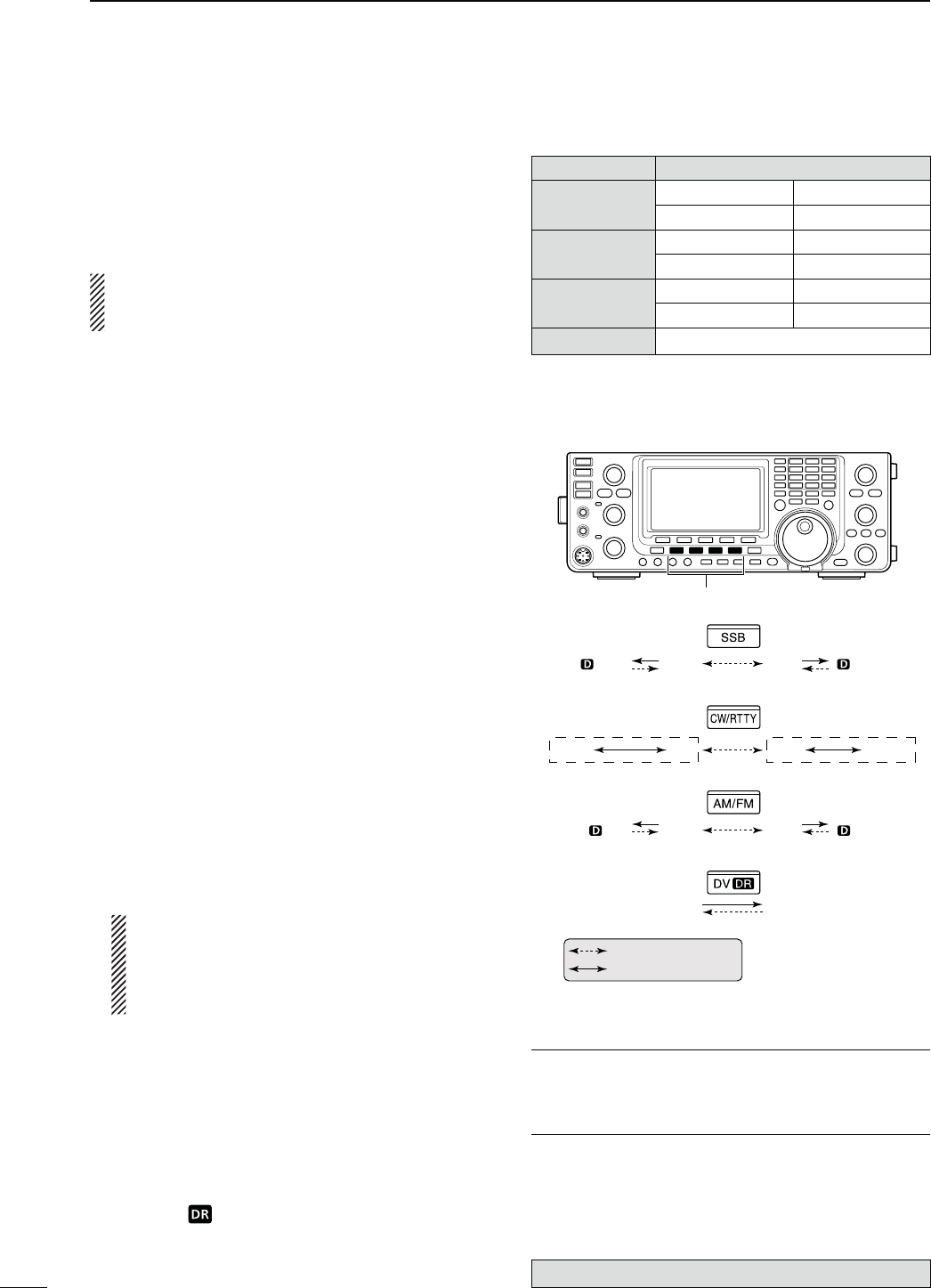
43
3BASIC OPERATION
N/PERATINGMODESELECTION
The usable operating modes in the IC-9100 are listed
to the right.
9OUCANSELECTTHEDESIREDOPERATINGMODEBYPUSH-
ing the mode switch.
See the diagram to the right for the order of selection.
9OU CAN MUTE THE MICROPHONE SIGNALS WHEN THE
data mode is selected, depending on the “DATA
MOD” option in the Set mode (p. 167).
s3ELECTINGTHE33"MODE
±Push [SSB] to select the USB or LSB mode.
sh,3"vORh53"vAPPEARS
s7HENOPERATINGABOVE-(Z53"ISSELECTEDlRST
when operating below 10 MHz, LSB is selected first.
s0USH;33"=AGAINTOTOGGLEBETWEEN53"AND,3"
s!FTER 53" OR ,3"ISSELECTEDHOLDDOWN ;33"=FOR
1 second to select the data mode. (“D” appears)
s)NTHEDATAMODEPUSH;33"=TORETURNTOTHENORMAL
SSB mode.
s3ELECTINGTHE#72449MODE
±0USH;#72449=TOSELECTTHE#7OR2449MODE
sh#7vORh2449vAPPEARS
s0USH ;#72449= AGAIN TO TOGGLE BETWEEN #7 AND
2449
s!FTER#7OR2449ISSELECTEDHOLDDOWN;#72449=
for 1 second to toggle between normal and reverse
modes.h#72vORh24492vAPPEARS
s3ELECTINGTHE!-&-MODE
±Push [AM/FM] to select the AM or FM mode.
sh!-vORh&-vAPPEARS
s
0USH;!-&-=AGAINTOTOGGLEBETWEEN!-AND&-
s!FTER !-OR&- ISSELECTEDHOLD DOWN;!-&-= FOR
1 second to select the data mode. (“D” appears)
s)NTHEDATAMODEPUSH;!-&-=TORETURNTOthe normal
AM or FM mode.
NOTE:
s)NTHE!-MODEYOUCANTRANSMITONONLYTHE
HF/50MHz frequency bands.
s4HE!-MODECANNOTBESELECTEDONTHE
MHz frequency band.
s3ELECTINGTHE$6MODEINCLUDING$2MODE
±0USH;$6s$2=TOSELECTTHE$6MODE
sh$6vAPPEARS
s$6MODEDIGITALVOICELOWSPEEDDATACOMMUNICA-
tion) allows you to exchange the text message and call
sign, and transmit a position data with a third-party GPS
receiver.
±(OLD DOWN ;$6s$2= TO TURN THE $2 $34!2®
Repeater) mode operation ON or OFF.
s“DV” and “ ” appears.
s4HE$6MODEISAUTOMATICALLYSELECTEDWHENTHE$2
mode is ON.
s$2$34!22EPEATERMODEALLOWSYOUTOUSEARE-
peater list to operate a D-STAR repeater simply.
The optional UT-121 is required for DV mode operation.
Mode switches
USBUSB
AMAM
LSB LSB
CW-R CW RTTY RTTY-R
FM FM
DV DR
: Push momentary
: Hold down for 1 second
s5SABLEOPERATINGMODES
-ODESWITCH /PERATINGMODE
;33"= USB USB Data
LSB LSB Data
[CW/RTTY] CW CW Reverse
2449 24492EVERSE
[AM/FM] AM AM Data
FM FM Data
;$6s$2= DV
INFORMATION!
The DV mode can be selected in either MAIN or SUB
band. If you select the DV mode in both Bands, the
transceiver cannot receive on the SUB Band.
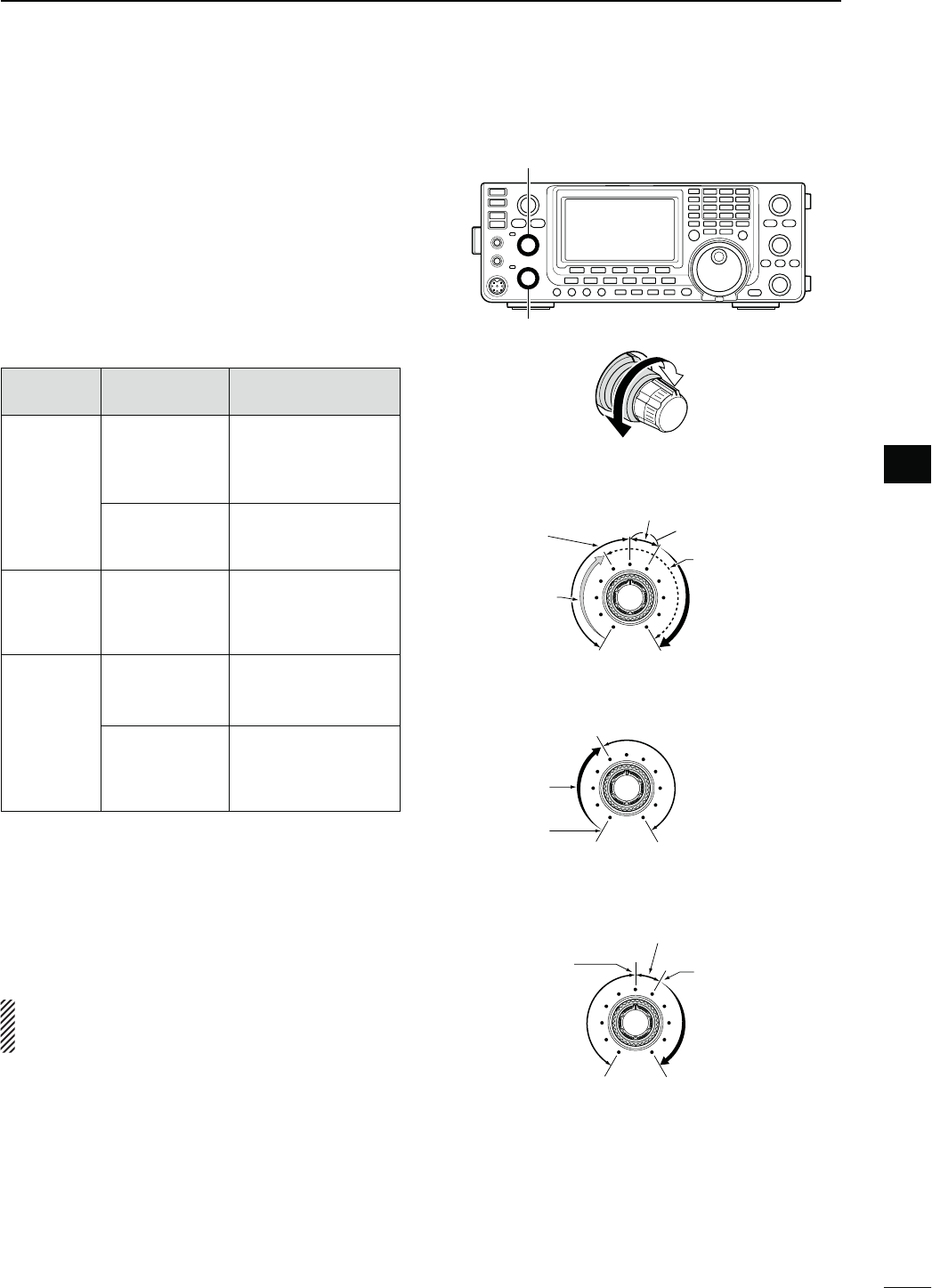
N3QUELCHANDRECEIVE2&SENSITIVITY
Adjusts the RF gain and squelch threshold level. The
squelch removes noise output to the speaker when no
signal is received (closed squelch).
s4HESQUELCHISPARTICULARLYEFFECTIVEFOR!-AND&-BUTCAN
also be used in other modes.
s4HETOOCLOCKPOSITIONISRECOMMENDEDFORthe most
effective use of the [RF/SQL] control.
s;2&31,=CANOPERATEASONLYAN2&GAINCONTROLSquelch
is fixed open) or only a squelch control (RF gain is fixed at
maximum sensitivity) depending on the
“RF/SQL Control”
option in
the Set mode. (p. 162)
SET MODE
SETTING
OPERATING
MODE
[RF/SQL]
OPERATION
RF+SQL
(default)
FM/DV
Operates as an RF
gain control, and
a noise squelch or
Smeter squelch.
33"#72449
AM
Operates as an RF
gain control, and an
Smeter squelch.
SQL ALL
Operates as only a
squelch control.
s2& GAIN IS FIXED AT
maximum sensitivity.
AUTO
33"#72449
Operates as only an
RF gain control.
s3QUELCHISlXEDOPEN
AM/FM/DV
Operates as only a
squelch control.
s2& GAIN IS FIXED AT
maximum sensitivity.
M!DJUSTING2&GAIN(Receive sensitivity)
Normally, [RF/SQL] is set to the 12 o’clock position.
Rotate [RF/SQL] to the 11 o’clock position for maxi-
mum sensitivity.
s2OTATINGCOUNTERCLOCKWISEFROMTHEMAXIMUMPOSITIONRE-
duces sensitivity.
s4HE3METERINDICATESRECEIVESENSITIVITY
While rotating the RF gain control, noise may be
heard. This comes from the DSP unit and does not
indicate an equipment malfunction.
M!DJUSTINGSQUELCH(Removing non-signal noise)
Rotate [RF/SQL] clockwise when no signal is received,
until the noise just disappears.
s4HE4828INDICATORLIGHTGOESOUT
s2OTATING;2&31,=PASTTHETHRESHOLDPOINTACTIVATESTHE
S-meter squelch— this allows you to set a minimum signal
level needed to open the squelch.
[RF/SQL](MAIN Band)
[RF/SQL](SUB Band)
s7HENFUNCTIONINGASAN2&GAINSQUELCHCONTROL
Maximum
RF gain
S-meter
squelch
Noise squelch (FM/DV modes)
Squelch is
open.
RF gain
adjustable
range
Recommended level
s7HENFUNCTIONINGASAN2&GAINCONTROL
3QUELCHISlXEDOPEN33"#72449ONLY
Minimum RF gain
Adjustable
range
Maximum
RF gain
s7HENFUNCTIONINGASASQUELCHCONTROL
(RF gain is fixed at maximum.)
Squelch is
open.
S-meter
squelch
S-meter squelch
threshold
Noise squelch
threshold
(FM mode)
Shallow Deep
Noise squelch (FM/DV modes)
44
3
BASIC OPERATION
3
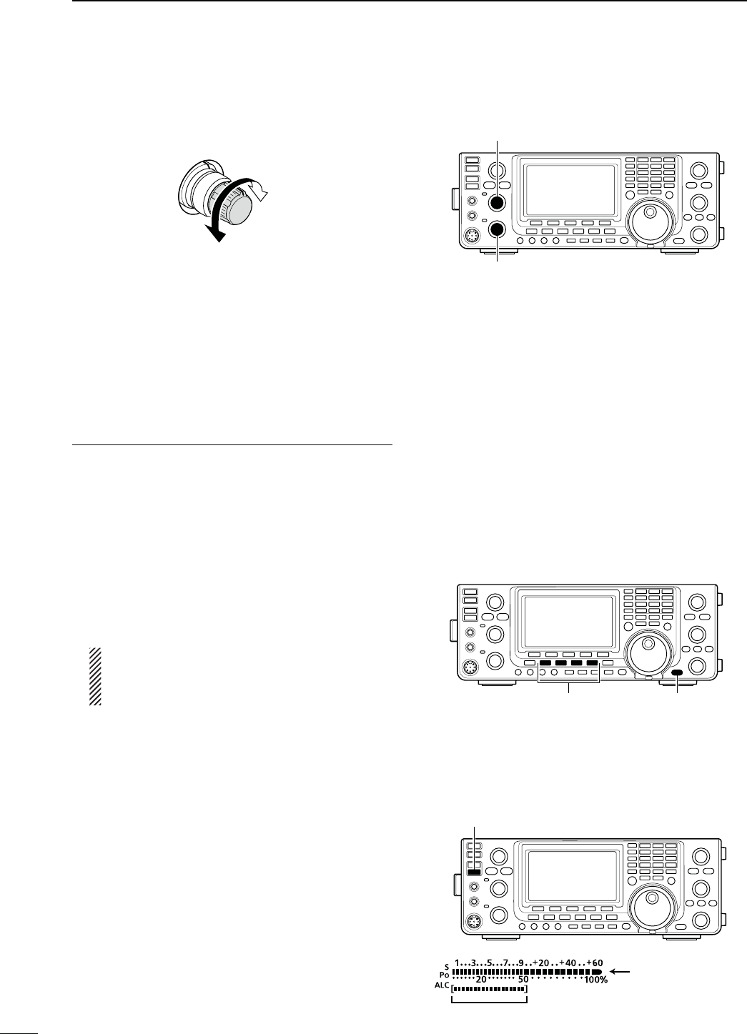
45
3BASIC OPERATION
N6OLUMESETTING
± Rotate the [AF] control clockwise to increase the
audio output level, counterclockwise to decrease it.
Increases
Decreases
N6OICESYNTHESIZEROPERATION
The IC-9100 has a built-in voice synthesizer to an-
nounce the operating frequency, mode and S-meter
level in clear, electronically-generated voice, in English
(or Japanese).
First, select the desired parameters to be announced
in the Set mode. (p. 164)
)NITIALVALUESFORTHEVOICESYNTHESIZERPARAMETERS
s30%%#(,EVEL
s30%%#(,ANGUAGE %NGLISH
s30%%#(3PEED ()'(
s30%%#(3,EVEL /.
s30%%#(;-/$%=37/&&
s;30%%#(,/#+=3730%%#(,/#+
(See NOTE as described below.)
± Push [SPEECH/LOCK] to announce the currently
selected frequency, mode and S-meter level*.
* The S-meter level announcement can be turned OFF. (p.
164)
NOTE: If “SPEECH/LOCK” is not selected in the
“[SPEECH/LOCK] SW” item of the Set mode,
you should hold down [SPEECH/LOCK] for 1
second to activate the voice synthesizer. (p. 164)
± Push a mode switch to announce the appropriate
mode, when the “SPEECH [MODE] SW” item is set
to “ON” in the Set mode. (p. 164)
N-ETER$ISPLAYSELECTION
The transmit meter can be toggled between three
functions for your convenience.
The RF power meter is always displayed.
±(OLDDOWN;!.4s-%4%2=FORSECONDTOTOGGLETHE
transmit meter function between SWR, ALC and
COMP.
s372 $ISPLAYSTHE372OFTHEANTENNAATTHEFRE-
quency.
s!,#
Displays the ALC level. When the meter move-
ment shows the input signal level exceeds the
allowable level, the ALC limits the RF power. In
such cases, decrease the microphone gain level.
s#/-0$ISPLAYS THE COMPRESSION LEVEL WHEN THE
speech compressor is in use.
[AF](MAIN Band)
[AF](SUB Band)
Mode switches [SPEECH/LOCK]
]
When ALC meter
is selected.
RF output power is
DISPLAYED IN PER-
cent), and it becomes
the S-meter in receive.
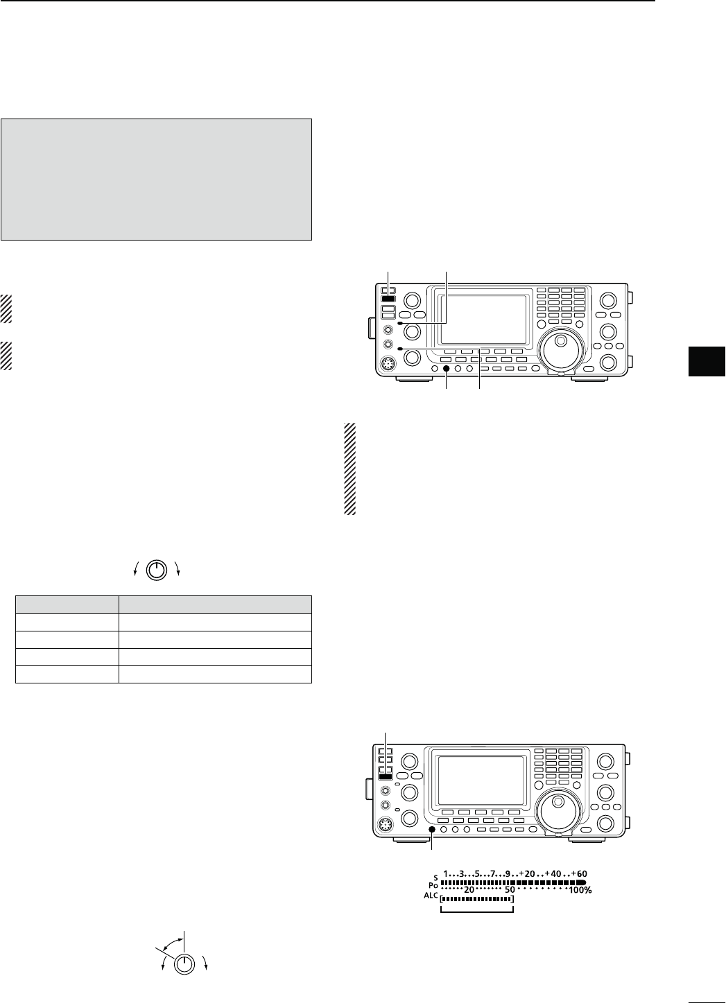
N"ASICTRANSMITOPERATION
"EFORETRANSMITTINGMONITORTHEOPERATINGFRE-
QUENCYTOMAKESURETRANSMITTINGWONTCAUSE
INTERFERENCETOOTHERSTATIONSONTHESAMEFRE-
QUENCY)TSGOODAMATEURPRACTICETOLISTENlRST
ANDTHENEVENIFNOTHINGISHEARDASKh)STHEFRE-
QUENCYINUSEvONCEORTWICEBEFOREYOUBEGIN
OPERATINGONTHATFREQUENCY
D4RANSMITTING
CAUTION: Transmitting without an antenna may
damage the transceiver.
In the AM mode, you can transmit on only the
HF/50MHz frequency bands.
q Push [PTT] on the microphone to transmit. (or
[TRANSMIT] on the transceiver)
s4HE-!)."AND4828INDICATORLIGHTSRED
s7HENINTHESATELLITEMODETHE35""AND4828INDI-
cator lights red. (p. 156)
w Release [PTT] again to receive. (or push [TRANS-
MIT])
Adjusting the transmit output power
±Rotate [RF POWER].
IncreasesDecreases
&REQUENCYBAND 2&OUTPUTPOWERRANGE
HF/50 MHz 2 to 100 W (AM: 2 to 30 W)
144 MHz 2 to 100 W
430 MHz 2 to 75 W
1200 MHz 1 to 10 W
D-ICROPHONEGAINADJUSTMENT
-ODE33"!-&-$6
q Push [PTT] to transmit.
s3PEAKINTOTHEMICROPHONEATYOURNORMALVOICELEVEL
w )NTHE33"MODE
(OLDDOWN;!.4s-%4%2=FORSECONDTOSELECTTHE
ALC meter. And then, while speaking into the mi-
crophone, rotate [MIC GAIN] so that the ALC meter
reading stays within the ALC zone.
)NTHE!-&-AND$6MODES
While speaking into the microphone, rotate
[MIC GAIN] with another station listening to your
voice for clarity.
Recommended level for
Icom microphones
IncreasesDecreases
e Release [PTT] to receive.
46
3
BASIC OPERATION
3
[TRANSMIT]
[RF POWER]
MAIN Band TX/RX indicator
SUB Band TX/RX indicator
ALC zone
]
]
NOTE: When you transmit on the HF/50 MHz fre-
quency bands, while monitoring an out of the ama-
teur band frequency on VHF or UHF on the SUB
band, the squelch on the SUB Band closes. There-
fore, you cannot receive on the VHF or UHF fre-
quency.
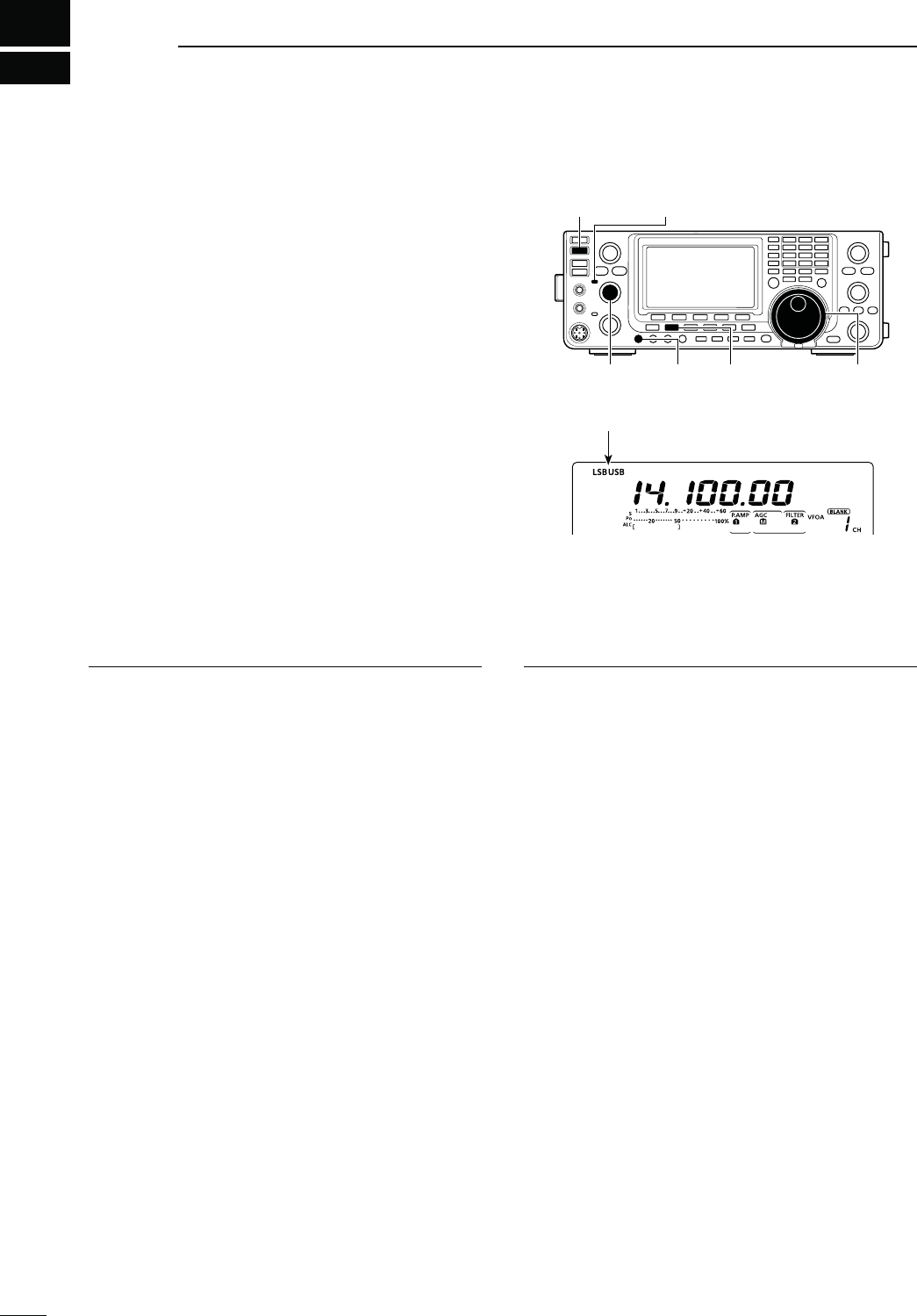
4
47
RECEIVE AND TRANSMIT
N/PERATING33"
q Select the desired frequency band. (p. 35)
w Push [SSB] to select the LSB or USB mode.
s7HENOPERATINGABOVE-(Z53"ISSELECTEDlRST
when operating below 10 MHz, LSB is selected first.
s!FTER53"OR,3"ISSELECTEDHOLDDOWN;33"=FOR
second to select the data mode, if needed.
e Rotate [MAIN DIAL] to tune a desired signal.
s4HE3METERINDICATESTHERECEIVEDSIGNALSTRENGTH
s
The tuning step can be changed using the tuning step
program mode. (p. 38)
r Rotate [AF] (MAIN Band) to adjust the audio to a
comfortable listening level.
t Push [PTT] on the microphone to transmit. (or
[TRANSMIT] on the transceiver)
s4HE4828INDICATOR-!)."ANDLIGHTSRED
y Speak into the microphone at your normal voice
level.
s2OTATE;-)#'!).=TOADJUSTTHEMICROPHONEGAINATTHIS
step, if necessary.
u Release [PTT] to receive. (or push [TRANSMIT]
again)
[TRANSMIT] TX/RX indicator (MAIN Band)
[MIC GAIN][AF]
(MAIN Band)
[SSB] [MAIN DIAL]
“LSB” or “USB” appears
#ONVENIENT2ECEIVEFUNCTIONS
s0REAMPANDATTENUATORP
s4WIN0"4PASSBANDTUNINGP
s!'#AUTOGAINCONTROLP
s.OISEBLANKERP
s.OISEREDUCTIONP
s.OTCHlLTERP
s63#VOICESQUELCHCONTROLP
#ONVENIENT4RANSMITFUNCTIONS
s3PEECHCOMPRESSORP
s6/8VOICEOPERATEDTRANSMITP
s4ONECONTROLP
s4RANSMITQUALITYMONITORP
s4RANSMITlLTERWIDTHP
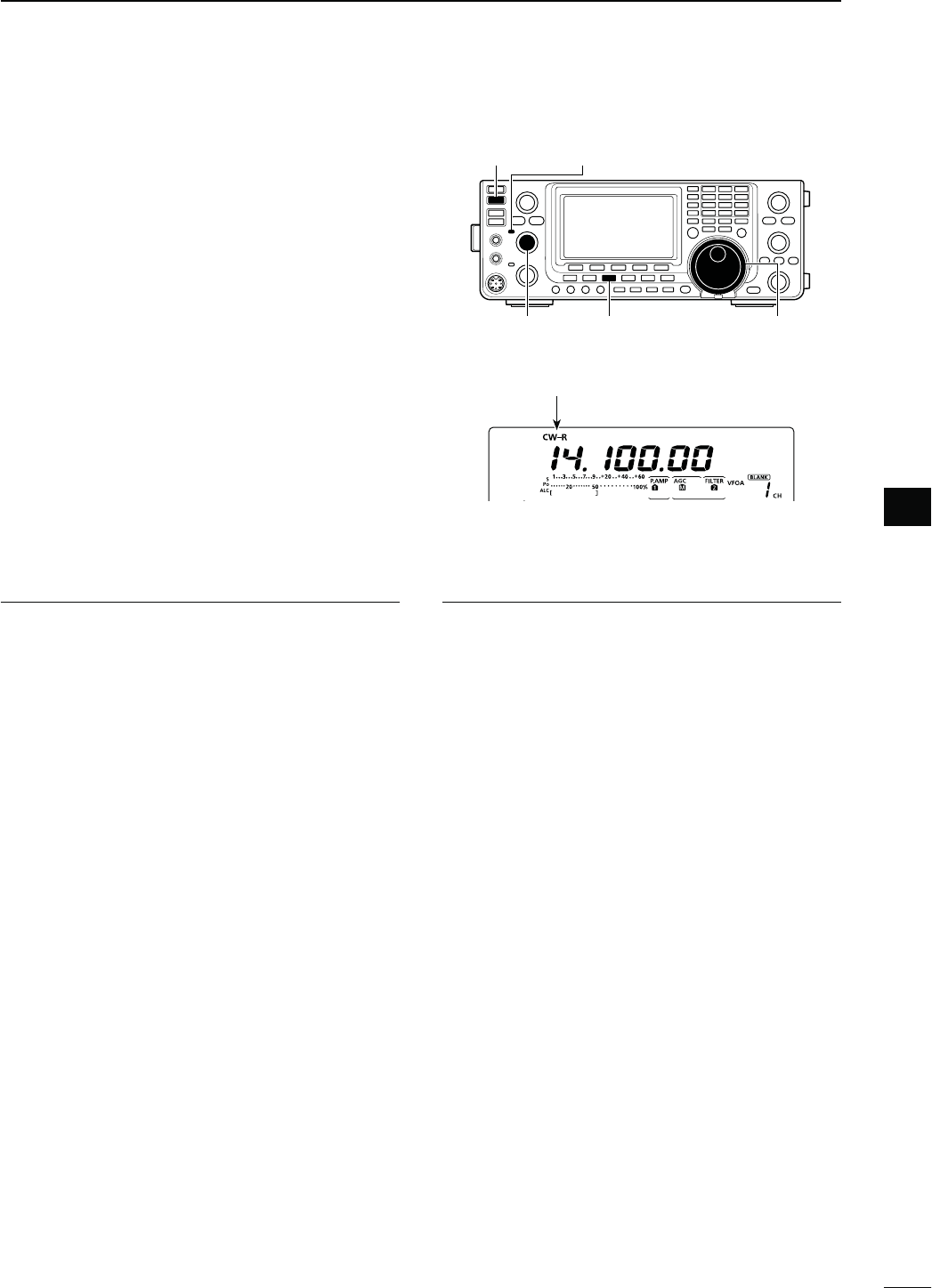
48
4
RECEIVE AND TRANSMIT
4
N/PERATING#7
q Select the desired frequency band. (p. 35)
w0USH;#72449=TOSELECT#7
s!FTERTHE#7MODEISSELECTEDHOLDDOWN;#72449=
for 1 second to toggle between CW and CW-R modes,
if necessary.
e Rotate [MAIN DIAL] to tune a desired signal.
s4HE3METERDISPLAYSTHERECEIVEDSIGNALSTRENGTH
s
The tuning step can be changed using the tuning step
program mode. (p. 38)
r Rotate [AF] (MAIN Band) to adjust the audio to a
comfortable listening level.
t Push [TRANSMIT] to transmit.
s4HE4828INDICATOR-!)."ANDLIGHTSRED
y Use the electric keyer or paddle to key your CW
signals.
s
The Po meter indicates transmitted CW output power.
u!DJUST#7SPEEDWITH;+%930%%$=
s!DJUSTABLEBETWEENANDWPMWORDSPERMINUTE
i Push [TRANSMIT] to receive.
[TRANSMIT] TX/RX indicator (MAIN Band)
[CW/RTTY] [MAIN DIAL][AF]
(MAIN Band)
#ONVENIENT2ECEIVEFUNCTIONS
s0REAMPANDATTENUATORP
s4WIN0"4PASSBANDTUNINGP
s!'#AUTOGAINCONTROLP
s.OISEBLANKERP
s.OISEREDUCTIONP
s-ANUAL.OTCHlLTERP
s#7PITCHCONTROLP
s¼ function (p. 39)
#ONVENIENT4RANSMITFUNCTIONS
s"REAKINFUNCTIONP
s+EYINGSPEEDSETTINGP
s-EMORYKEYERP
“CW” or “CW-R” appears
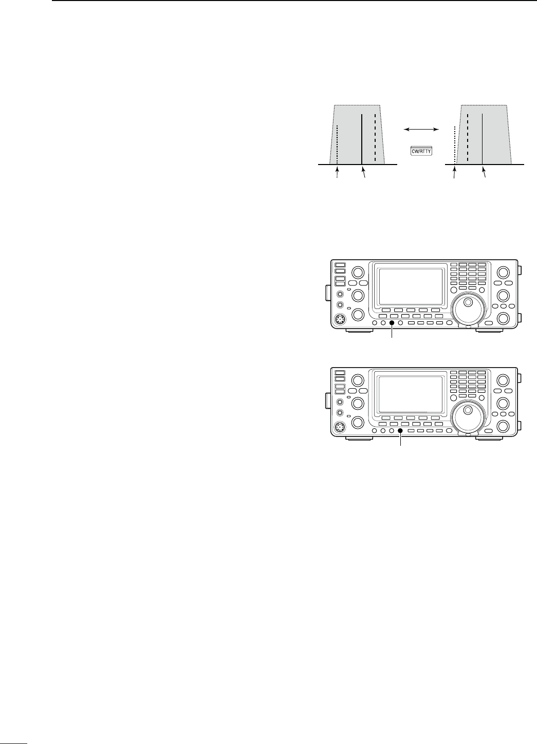
49
4RECEIVE AND TRANSMIT
BFO
CW-R mode (USB side)
BFO
Desired signal
CW mode (LSB side)
Interference Desired signalInterference
N Operating CW (Continued)
D About the CW reverse mode
The CW reverse mode receives signals with a reverse
side CW carrier point similar to voice LSB and USB
modes.
Use when interfering signals are near a desired signal
and you want to reduce the interfering tone.
q
0USH;#72449=
once or twice
to select the CW
mode.
w(OLDDOWN;#72449=FORSECONDTOTOGGLEBE-
tween CW and CW-R mode, if necessary.
s#HECKTHATTHEINTERFERINGTONECANBEREDUCED
D!BOUT#7PITCHCONTROL
The received CW audio pitch and CW sidetone can be
adjusted to suit your preference without changing the
operating frequency.
± Rotate [CW PITCH] to suit your preference.
s!DJUSTABLEFROMTO(ZIN(ZSTEPS
D!BOUTKEYINGSPEED
The transceiver’s internal electronic keyer speed can
be adjusted to between 6 and 48 wpm (words per min-
ute).
±2OTATE;+%930%%$=CLOCKWISETOINCREASEKEYING
SPEEDCOUNTERCLOCKWISETODECREASEIT
D#7SIDETONEFUNCTION
When the transceiver is in the receive mode (and the
Break-in function is OFF— p. 79), you can listen to the
CW sidetone without actually transmitting.
9OUCANALSO USETHE#7SIDETONETOPRACTICE#7
sending, but be sure to turn OFF the Break-in func-
tion.
The CW sidetone level can be adjusted in the “Side
Tone Level” item of the Keyer Set mode (p. 54).
[CW PITCH]
[KEY SPEED]
Hold down
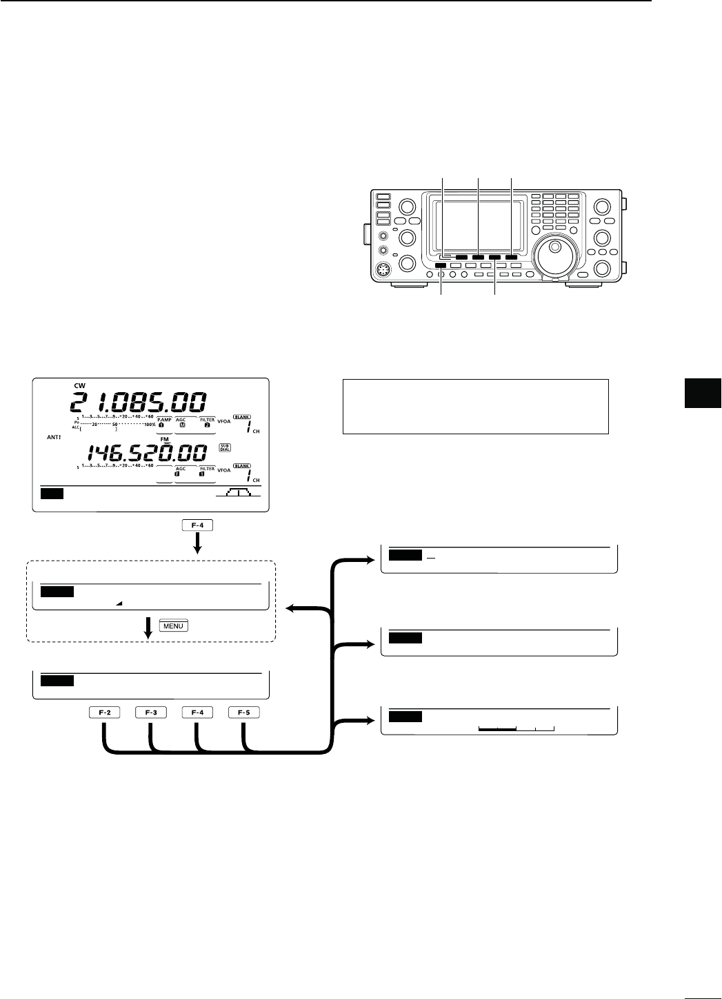
50
4
RECEIVE AND TRANSMIT
4
N%LECTRONICKEYERFUNCTIONS
9OU CAN ACCESS A NUMBER OF CONVENIENTFUNCTIONS
of the built-in electronic keyer in the memory keyer
menu.
q
In the CW mode,
push [MENU] to display the “M1”
screen (Menu 1).
w0USH;+%9=&TODISPLAYTHEh+%9vSCREEN-EM-
ory Keyer).
e Push [SEND](F-2), [EDT](F-3), [001](F-4) or [SET]
(F-5) to select the desired menu.
See the diagram below.
s0USH;-%.5=TORETURNTOTHEPREVIOUSDISPLAY
AGC DUP 1⁄4 KEY SCP
M1
SEND EDT 001 SET
KEY
1
Normal
001
Number Style
1
50%
SET
Side Tone Level
DEL SPC
EDT CQ TEST CQ TEST DE
M1
M1 M2 M3 M4 –1
SEND
001
s-EMORY+EYERSCREEN
s+EYER3ENDSCREEN (p. 51)
s+EYER%DITSCREEN (p. 52)
s#ONTEST.UMBER3ETMODE (p. 53)
s+EYER3ETMODE (p. 54)
[F-2]
[F-3]
[F-4]
[F-5]
[SEND]
[MENU] [KEY]/[001]
[SEND] [EDT] [SET]
D-EMORYKEYERMENUCONSTRUCTION
The screen you want to appear first can be
SELECTEDINTHEh+%9%2ST-ENUvITEMOF
the Set mode. (p. 165)
Push
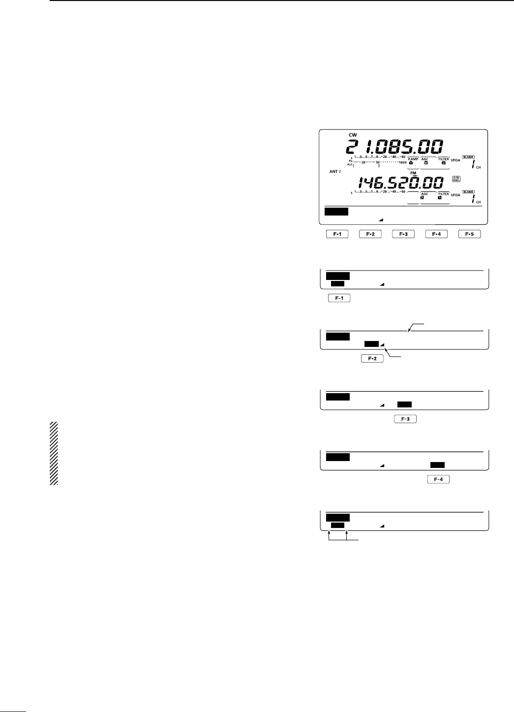
51
4RECEIVE AND TRANSMIT
N Electronic keyer functions (Continued)
D-EMORYKEYERSENDMENU
Pre-set characters can be sent using the Keyer Send
menu. Contents of the memory keyer are set in the
Edit menu.
s4RANSMITTING
q
In the CW mode, p
ush [MENU] to display the “M1”
screen (Menu 1).
w0USH;+%9=&TODISPLAYTHEh+%9vSCREEN-EM-
ory Keyer).
e Push [SEND](F-2) to display the “SEND” screen
(Keyer Send).
r Push [TRANSMIT] to switch the transceiver to
transmit, or turn ON the Break-in function. (p. 79)
t Push one of the function keys, [M1](F-1) to
[M4](F-4), to send the memory keyer contents.
s(OLDINGDOWNAFUNCTIONKEYFORSECONDREPEATEDLY
SENDSTHECONTENTSPUSHANYFUNCTIONKEYTOCANCELTHE
transmission.
s4HE CONTEST NUMBER COUNTER ADVANCES EACH TIME THE
contents are sent.
s0USH;=&TOREDUCETHECONTESTNUMBERADVANCES
by 1 before sending the memory keyer contents to a
station a second time.
s3ETTHEMEMORYKEYERREPEATINTERVALTOBETWEENAND
60 seconds (1 second steps) in the “Keyer Repeat Time”
item of the Keyer Set mode. (p. 54)
y0USH;-%.5=TORETURNTOTHEh+%9vSCREEN-EM-
ory Keyer).
u
Push [MENU] to return to the “M1” screen (Menu 1).
For your information
When an external keypad is connected to pin 3 and
pin 7 of the [MIC] connector, the contents of M1 to
M4 can be transmitted without selecting the keyer
send menu.
See page 167 for details.
M1 M2 M3 M4 –1
SEND
001
CQ TEST CQ TE
M1 M2 M3 M4 –1
SEND
001
UR 5NN001 BK
M1 M2 M3 M4 –1
SEND
001
CFM TU
M1 M2 M3 M4 –1
SEND
001
QRZ?
M1 M2 M3 M4 –1
SEND
001
CQ TEST CQ TE
M1][M2M3M4–1
SEND
001
s-SENDINGDISPLAY
s-SENDINGDISPLAY
s-SENDINGDISPLAY
s-SENDINGDISPLAY
s7HILETRANSMITTINGREPEATEDLY
Counter
Count up trigger icon
“ [ ” and “ ] ” appear
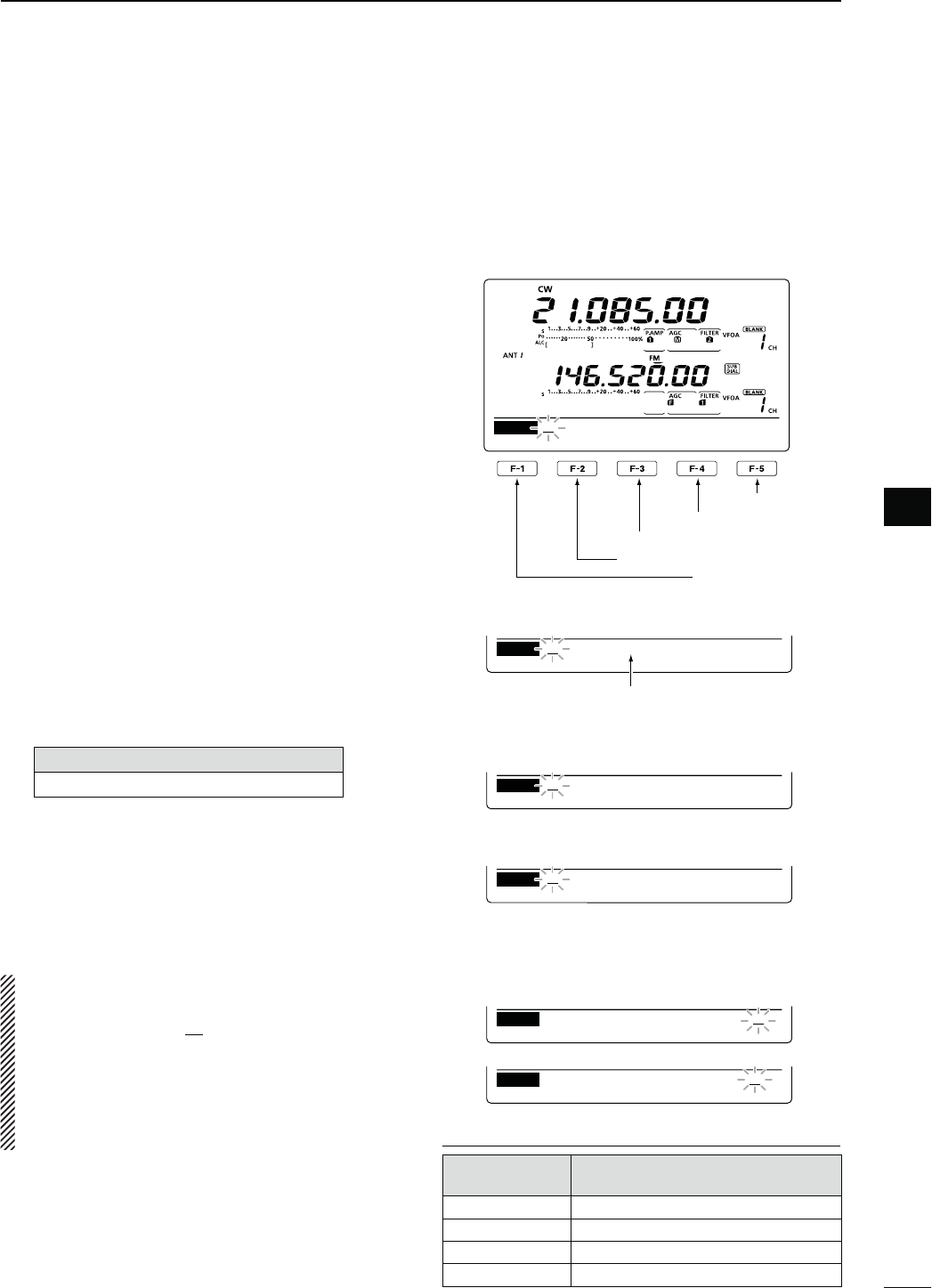
52
4
RECEIVE AND TRANSMIT
4
D%DITINGAMEMORYKEYER
The contents of the memory keyer memories can be
set using the memory keyer edit menu. The memory
keyer can memorize and re-transmit 4 CW key codes
for often-used CW sentences, contest numbers or
a count up trigger. The total capacity of the memory
keyer is 70 characters per memory channel.
s0ROGRAMMINGCONTENTS
q
In the CW mode, p
ush [MENU] to display the “M1”
screen (Menu 1).
w0USH;+%9=&TODISPLAYTHEh+%9vSCREEN-EM-
ory Keyer).
e Push [EDT](F-3) to display the “EDT” screen (Keyer
Edit).
s4HE MEMORY KEYER CONTENT OF #HANNEL - IS DIS-
played.
r Push [F-1] one or more times to select the memory
keyer channel to be edited.
t Rotate [MAIN DIAL] to select the desired character
or symbol.
When inputting numbers or a decimal point, push
the appropriate keypad key.
s0USH;$%,=&TODELETETHESELECTEDCHARACTERSYM-
bol or number.
s0USH;30#=&TOINPUTASPACE
s7HENTHEPREPROGRAMMEDMEMORYKEYERREACHES
characters, an error beep sounds. In this case, push [Ω]
(F-2) or [≈](F-3) to select a character, then push [DEL]
(F-4) to delete it.
3ELECTABLECHARACTERSANDSYMBOLS
A to Z, ⁄ ? ^ . , @ 1
y Push [Ω](F-2) to move the cursor backwards, or
push [≈](F-3) to move the cursor forwards.
u Repeat steps t and y to program up to 70 char-
acters memory keyer contents.
i0USH ;-%.5= TO SAVE AND RETURN TO THE h+%9v
screen (Memory Keyer).
o
Push [MENU] to return to the “M1” screen (Menu 1).
NOTE:
“^” is used to transmit a string of characters with no
inter-character space. Put “^” before a text string such
as ^AR, and the string “AR” is sent with no space.
“1” is used to insert the CW contest number. The
number automatically advances by 1. This function
is available for only one memory keyer channel at
a time. “1” is used in memory keyer channel M2 by
default.
Input a space
Delete a character
Move the cursor forwards
Move the cursor backwards
Select M1 to M4
DEL SPC
EDT CQ TEST CQ TEST DE
M1
DEL SPC
EDT TU DE JA3YUA TEST
M3
DEL SPC
EDT QSL TU DE JA3YUA
M3
DEL SPC
EDT UR 5NNMBK
M2
DEL SPC
EDT CFM TU
M3
DEL SPC
EDT QRZ?
M4
s-DEFAULTINDICATION
s-DEFAULTINDICATION
s-DEFAULTINDICATION
%XAMPLE DISPLAY— Inputting “QSL TU
$%*!95!4%34vINTOTHEMEMORYKEYER
channel 3 (M3).
When inputting an asterisk, the
counter is incremented by 1.
0REPROGRAMMEDMEMORYKEYERCONTENTS
-EMORYKEYER
CHANNEL #ONTENTS
M1 CQ TEST CQ TEST DE JA1 JA1 TEST
M2 UR 5NN1 BK
M3 CFM TU
M4 QRZ?
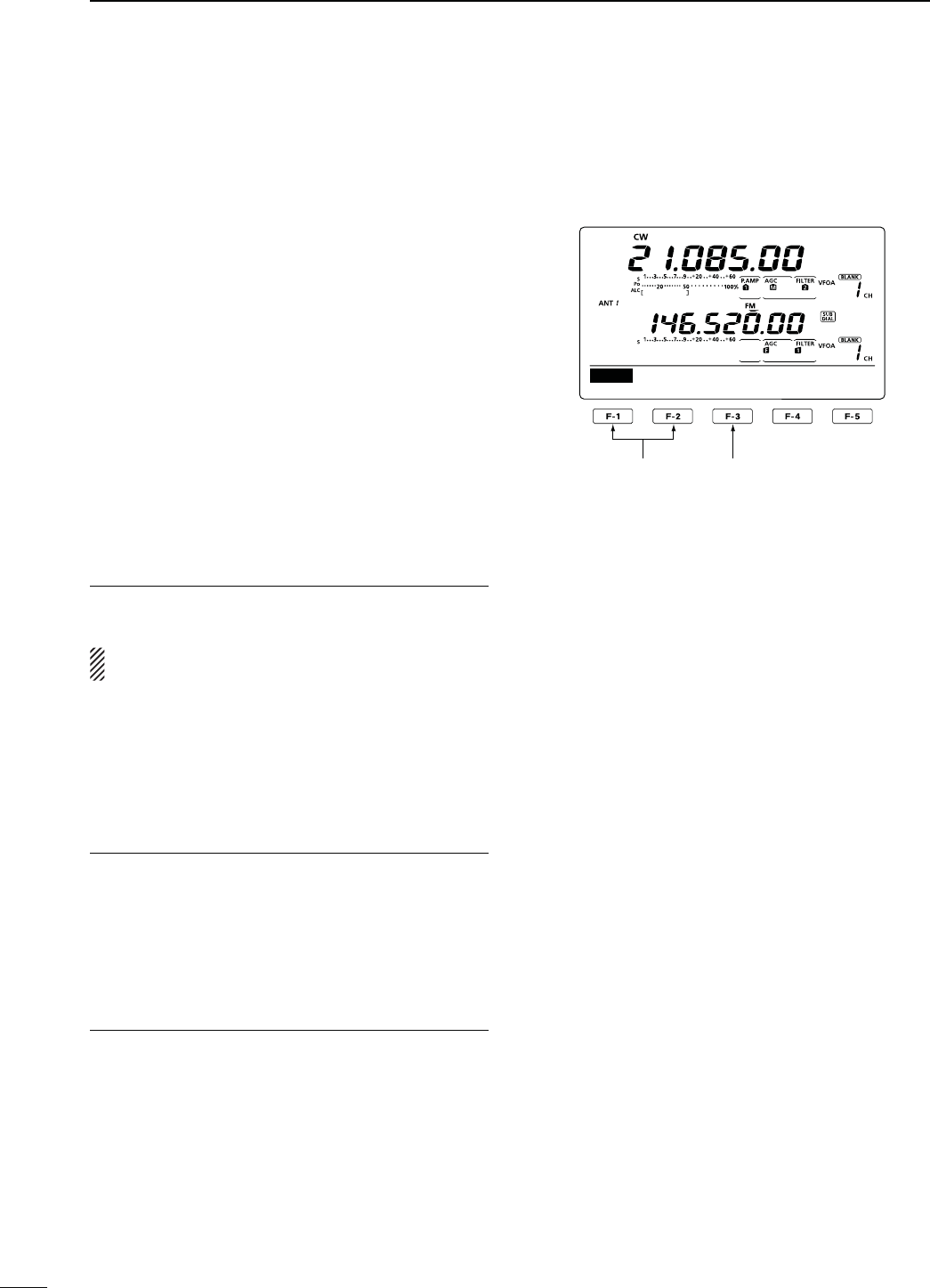
53
4RECEIVE AND TRANSMIT
N Electronic keyer functions (Continued)
D#ONTESTNUMBER3ETMODE
This mode is used to set the contest number, count up
trigger and Present number.
s3ETTINGCONTENTS
q
In the CW mode, p
ush [MENU] to display the “M1”
screen (Menu 1).
w0USH;+%9=&TODISPLAYTHEh+%9vSCREEN-EM-
ory Keyer).
e Push [001](F-4) to enter the Contest Number Set
mode.
r Push [Y](F-1) or [Z](F-2) to select the desired
item.
t Rotate [MAIN DIAL] to select the desired option.
s(OLDDOWN;&=FORSECONDTORESETTOTHEDEFAULTSET-
ting, if desired.
y0USH ;-%.5= TO SAVE AND RETURN TO THE h+%9v
screen (Memory Keyer).
u
Push [MENU] to return to the “M1” screen (Menu 1).
.UMBER3TYLE1. $EFAULT.ORMAL
This item sets the numbering system used for contest
numbers— normal or short morse numbers.
Short morse numbers are also referred to as “cut”
numbers.
s.ORMAL $OESNOTUSESHORTMORSENUMBERS
sANO : Sets 1 as A, 9 as N and 0 as O.
sANT : Sets 1 as A, 9 as N and 0 as T.
s NO : Sets 9 as N and 0 as O.
s NT : Sets 9 as N and 0 as T.
#OUNT5P4RIGGER2. $EFAULT-
Set the count-up trigger to one of four memory slots
for the contest number exchange. The count-up trigger
allows the contest number to automatically advance
after each complete number exchange is sent.
s---OR-CANBESET
0RESENT.UMBER3. $EFAULT5P$OWN
This item shows the current number for the count-up
trigger channel set above.
s2OTATE;-!).$)!,=TOCHANGETHENUMBERORHOLD
down [CLR](F-3) for 1 second to reset the current
number to 001.
1
Normal
001
Number Style
Select the item Reset to the default
setting
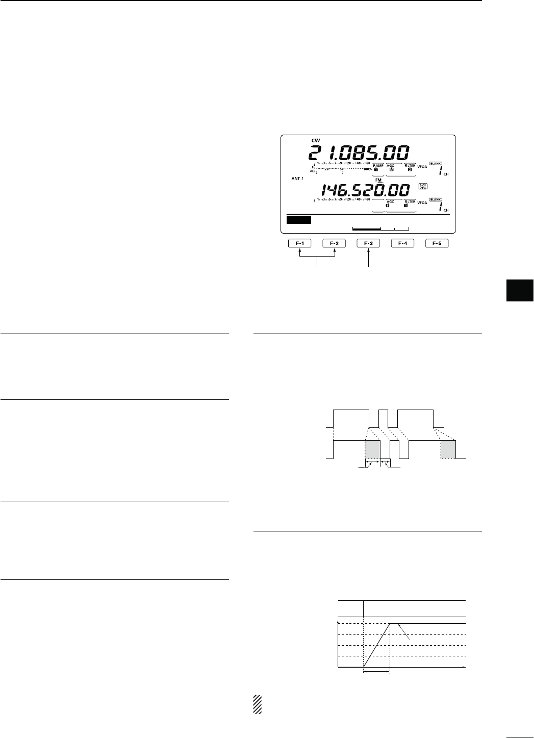
54
4
RECEIVE AND TRANSMIT
4
D Keyer Set mode
This Set mode is used to set the CW sidetone, mem-
ory keyer repeat time, dash weight, paddle specifica-
tions, keyer type, etc.
s3ETTINGCONTENTS
q
In the CW mode, p
ush [MENU] to display the “M1”
screen (Menu 1).
w0USH;+%9=&TODISPLAYTHEh+%9vSCREEN-EM-
ory Keyer).
e Push [SET](F-5) to enter the Keyer Set mode.
r Push [Y](F-1) or [Z](F-2) to select the desired
item.
t Rotate [MAIN DIAL] to select the desired option.
s(OLDDOWN;&=FORSECONDTORESETTOTHEDEFAULTSET-
ting, if desired.
y0USH ;-%.5= TO SAVE AND RETURN TO THE h+%9v
screen (Memory Keyer).
u
Push [MENU] to return to the “M1” screen (Menu 1).
3IDE4ONE,EVEL1. $EFAULT
Select the CW sidetone output level.
sTOINSTEPSCANBESELECTED
3IDE4ONE,,IMIT2. $EFAULT/.
Set the CW sidetone level limit. When the [AF] con-
trol is rotated above a specified level, the CW sidetone
does not increase.
s/. #7SIDETONELEVELISLIMITED
s/&SIDETONELEVELISNOTLIMITED
Keyer 3. 2EPEAT4IME $EFAULTS
When sending CW using the repeat timer, set the time
between transmission.
sTOSECONDSINSECONDSTEPSCANBESELECTED
-ESSAGE$ISPLAY4. $EFAULT.ORMAL
When you are in the “SEND” screen (Keyer Send),
channel numbers are displayed above the function
keys. However, you can display the first three char-
acters of the keyer message instead of the channel
number.
Select whether to display the channel number or the
first three characters of the keyer.
s.ORMAL $ISPLAYSTHECHANNELNUMBER
s-ESSAGE$ISPLAYSTHElRSTTHREECHARACTERSOFTHE
keyer message.
$OT$ASH2ATIO5. $EFAULT
Set the dot/dash ratio.
sTOINSTEPSCANBESELECTED
+EYINGWEIGHTEXAMPLEMorse code “K”
DASH
Weight setting:
1:1:3 (default)
Weight setting:
Adjusted
DASH
DOT (fixed*)
Adjustable range SPACE (fixed*)
*SPACE and DOT length can be
adjusted with only [KEY SPEED].
2ISE4IME6. $EFAULTMS
Set the rise time of the transmitted CW envelope.
sORMILLISECONDSCANBESELECTED
!BOUTRISETIME
Key action
Tx output power
Rise time
Tx
Rx
Set Tx power level
Time
0
Key clicks on nearby frequencies can be generated if
the rise time of a CW waveform is too short.
Continued on the next page.
1
50%
SET
Side Tone Level
Select the item Reset to the default
setting

55
4RECEIVE AND TRANSMIT
N Electronic keyer functions
D Keyer Set mode (continued)
0ADDLE0OLARITY7. $EFAULT./2-!,
Set the paddle polarity.
s.ORMALORREVERSEPOLARITYCANBESELECTED
+EYER4YPE8. $EFAULT%,%#+%9
3ELECTTHEKEYERTYPEFOR;%,%#+%9=CONNECTORON
the front panel.
s3TRAIGHTKEY"5'+%9OR%,%#+%9CANBESE-
lected.
-)#5P$OWN+EYER9. $EFAULT/&&
Set the microphone [UP]/[DN] switches to be used
as a key. (The microphone [UP]/[DN] switches do not
work as a “squeeze key.”)
s/. 4HE;50=;$.=SWITCHESCANBEUSEDASAKEY
for CW.
s/&&4HE;50=;$.=SWITCHESCANNOTBEUSEDASA
key for CW.
NOTE: When “ON” is selected, the frequency and
memory channels cannot be changed using the
[UP]/[DN] switches.
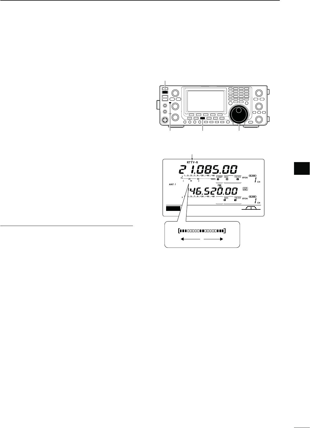
56
4
RECEIVE AND TRANSMIT
4
N/PERATING2449&3+
7HENUSINGYOUR2449TERMINALOR4.#CONSULTTHE
manual that comes with the equipment.
q Select the desired frequency band. (p. 35)
w
0USH;#72449=
once or twice
TOSELECTTHE2449
mode.
s!FTERTHE2449MODEISSELECTEDHOLDDOWN;#72449=
for 1 second to toggle between normal and reverse
modes, if needed.
e Rotate [MAIN DIAL] to tune a desired signal.
s4HE3METERINDICATESRECEIVEDSIGNALSTRENGTH
s)FTHERECEIVEDSIGNALCANNOTBEDEMODULATEDTRYTOSE-
LECTTHE2449REVERSEMODEINSTEPw.
s
The tuning step can be changed using the tuning step
program mode. (p. 38)
r Push [TRANSMIT] to set the transceiver to the
transmit mode, or transmit a SEND signal from your
TNC.
s4HE4828INDICATOR-!)."ANDLIGHTSRED
s4HE0O METER DISPLAYS THETRANSMITTED2449SIGNAL
strength.
t Use your connected PC or TNC (TU) to transmit
2449&3+SIGNALS
y Push [TRANSMIT] to receive.
#ONVENIENT2ECEIVEFUNCTIONS
s0REAMPANDATTENUATORP
s4WIN0"4PASSBANDTUNINGP
s!'#AUTOGAINCONTROLP
s.OISEBLANKERP
s.OISEREDUCTIONP
s.OTCHlLTERP
s¼ function (p. 39)
s4WIN0EAK&ILTERP
[TRANSMIT]
[CW/RTTY] [MAIN DIAL]
h2449vORh24492vAPPEARS
AGC DUP 1/4 RTTY SCP
M1
MAIN Band
TX/RX indicator
While receiving, the meter functions as the
2449TUNINGMETERTOMAKECORRECTTUNING
easier.
Rotate [MAIN DIAL] to the point where both
sides of the dots appear equally.
s7HILETRANSMITTINGTHEMETERFUNCTIONSAS
the transmit meter, SWR, ALC or COMP,
SELECTEDWITH;!.4s-%4%2=P
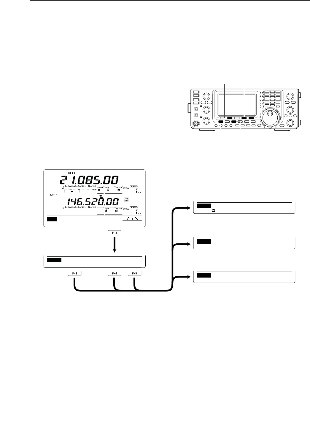
57
4RECEIVE AND TRANSMIT
N2449FUNCTIONS
4HE2449MENUHASANUMBEROFCONVENIENTFUNCTIONS
FOR2449OPERATION
q
0USH;#72449=
once or twice
TOSELECTTHE2449
mode.
s!FTERTHE2449MODEISSELECTEDHOLDDOWN;#72449=
for 1 second to toggle between normal and reverse
modes, if needed.
w Push [MENU] to display the “M1” screen (Menu 1).
e0USH;2449=&TODISPLAYTHEh2449vSCREEN
r Push [DEC](F-2), [TPF](F-4) or [SET](F-5) to select
the desired menu. See the diagram below.
s0USH;-%.5=TORETURNTOTHEPREVIOUSDISPLAY
D#ONSTRUCTIONOF2449MENU
[MENU] [CW/RTTY]
[RTTY]/[TPF] [SET]
[DEC]
AGC DUP 1/4 RTTY S C P
M1
DEC TPF SET
RTTY
RTTY
RTTY–TPF ON
1
2125
SET
RTTY Mark Freq
DEC
45BPS BAUDOT
MK ⁄ SFT 2125 ⁄ 170
F2 : HOLD F3 : CLR
ADJ
DEC TPF SET
s2449SCREEN
s2449$ECODERSCREEN (p. 59)
s4WIN0EAK&ILTERSETTINGSCREEN (p. 58)
s24493ETMODE (p. 60)
[F-2]
[F-4]
[F-5]
Push
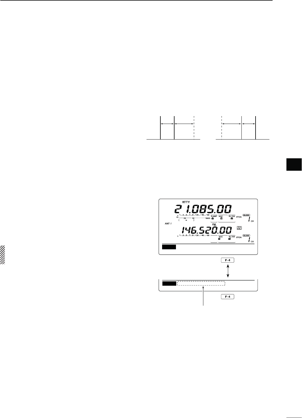
58
4
RECEIVE AND TRANSMIT
4
D About RTTY reverse mode
Received characters are occasionally garbled when
the Mark and Space signals are reversed. This rever-
sal can be caused by incorrect TNC connections, set-
ting or commands.
4ORECEIVEREVERSED2449SIGNALSCORRECTLYSELECTTHE
2449REVERSEMODE
±)NTHE2449MODEHOLDDOWN;#72449=FORSEC-
ONDTOSELECTTHE2449REVERSEMODE
sh24492vAPPEARSWHENTHE2449REVERSEMODEISSE-
lected.
s(OLDDOWN;#72449=FORSECONDAGAINTOSELECTTHE
normal mode.
D4WIN0EAK&ILTER
The Twin Peak Filter changes the receive frequency
response by boosting 2125 and 2295 Hz for better
COPYINGOF2449SIGNALS
q)NTHE2449MODEPUSH;-%.5=TODISPLAYTHEh-v
screen (Menu 1).
w0USH;2449=&TODISPLAYTHEh2449vSCREEN
e Push [TPF](F-4) to turn the Twin Peak Filter ON or
OFF.
r Push [MENU] to return to the previous display.
NOTE: When the Twin Peak Filter is in use, the re-
CEIVEDAUDIOOUTPUTMAYINCREASE4HISISNORMAL
not a malfunction.
Normal Reverse
170
Hz
170
Hz
2125
Hz
2125
Hz
BFOBFO Space
Space Mark
Mark
DEC TPF SET
RTTY
RTTY
RTTY–TPF ON
DEC TPF SET
Appears when the Twin Peak
filter is turned ON.
Push
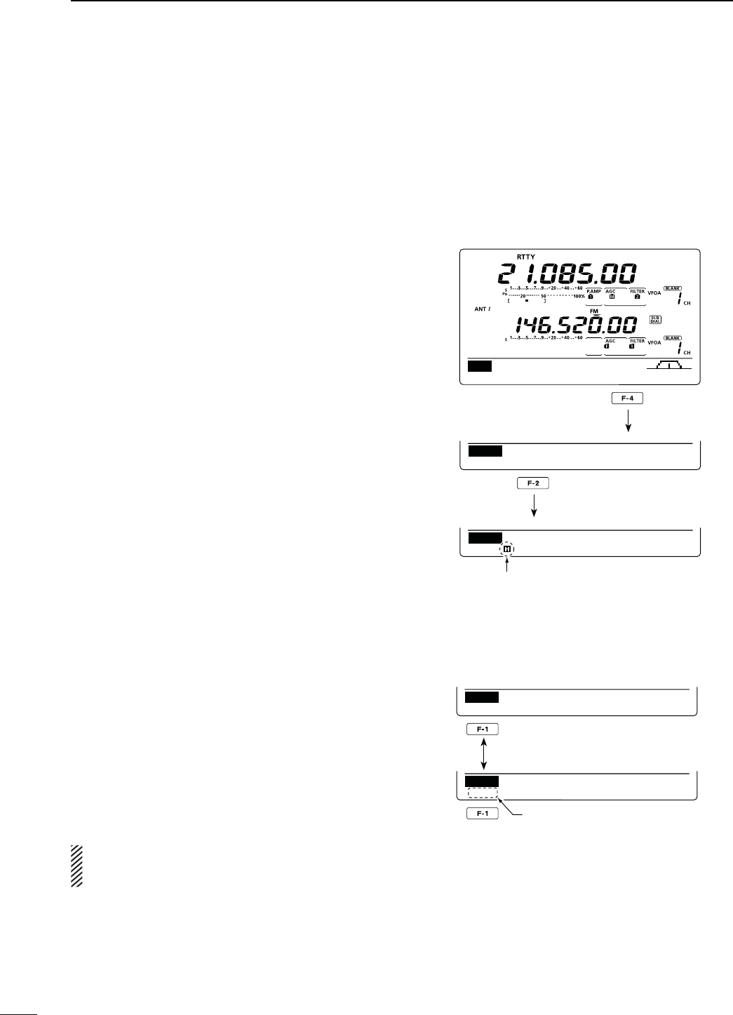
59
4RECEIVE AND TRANSMIT
N2449FUNCTIONS#ONTINUED
D RTTY decoder
4HE TRANSCEIVER HAS AN 2449 DECODER FOR "AUDOT
(mark freq.: 2125 Hz, shift freq.: 170 Hz, 45 bps).
An external terminal unit (TU) or terminal node con-
nector (TNC) is not necessary for receiving a Baudot
signal.
q)NTHE2449MODEPUSH;-%.5=TODISPLAYTHEh-v
screen (Menu 1).
w0USH;2449=&TODISPLAYTHEh2449vSCREEN
e0USH;&=$%#TOTURN/.THE2449DECODER
s2449DECODERSCREENAPPEARS
r Push [F-2] to turn ON the Hold function to hold the
current screen.
shH” appears when this function is turned ON.
s0USH;&=AGAINTOTURN/&&THE(OLDFUNCTION
t Hold down [F-3] for 1 second to clear the displayed
characters.
shH” disappears at the same time as the displayed char-
acters are cleared. (The hold function is cancelled.)
y Push [MENU] to return to the previous display.
s3ETTINGTHEDECODERTHRESHOLDLEVEL
If some characters are displayed when no signal is re-
CEIVEDADJUSTTHE2449DECODERTHRESHOLDLEVEL
q3ELECT THE 2449 DECODER SCREEN AS DESCRIBED
above.
w Push [F-1](ADJ) to select the threshold level adjust-
ment mode.
e2OTATE;-!).$)!,=TOADJUSTTHE2449DECODER
threshold level.
s(OLDDOWN;&=FORSECONDTORESETTOTHEDEFAULTSET-
ting, if desired.
r Push [MENU] to return to the previous display.
The number of the decoder display lines, the Un-
Shift On Space (USOS) function and new line code
CANBESETINTHE24493ETMODEP
AGC DUP 1/4 RTTY S C P
M1
DEC TPF SET
RTTY
DEC
45BPS BAUDOT
MK ⁄ SFT 2125 ⁄ 170
F2 : HOLD F3 : CLR
ADJ
Appears when the Hold function
is turned ON.
Push
Push
DEC
45BPS BAUDOT
MK ⁄ SFT 2125 ⁄ 170
F2 : HOLD F3 : CLR
9
DEC
45BPS BAUDOT
MK ⁄ SFT 2125 ⁄ 170
F2 : HOLD F3 : CLR
ADJ
Threshold level display
Push
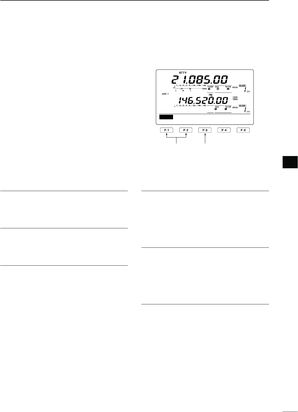
60
4
RECEIVE AND TRANSMIT
4
D RTTY Set mode
4HE24493ETMODEISUSEDTOSETTHEMARKANDSHIFT
frequencies, keying type, decode USOS function,
2449DECODERNEWLINECODEANDTHENUMBEROFDE-
code screen display lines.
s3ETTINGCONTENTS
q
)NTHE2449MODEP
ush [MENU] to display the “M1”
screen (Menu 1).
w0USH;2449=&TODISPLAYTHEh2449vSCREEN
e0USH;3%4=&TOENTERTHE24493ETMODE
r Push [Y](F-1) or [Z](F-2) to select the desired
item.
t Rotate [MAIN DIAL] to select the desired option.
s(OLDDOWN;&=FORSECONDTORESETTOTHEDEFAULTSET-
ting, if desired.
y0USH;-%.5=TOSAVEANDRETURNTOTHEh2449v
screen.
u
Push [MENU] to return to the “M1” screen (Menu 1).
2449-ARK&REQ1. $EFAULT
3ELECTTHE2449MARKFREQUENCY
sAND(ZARESELECTABLE
24493HIFT7IDTH2. $EFAULT
3ELECTTHE2449FREQUENCYSHIFT
sAND(ZARESELECTABLE
2449+EYING0OL3. $EFAULT./2-!,
Select normal or reverse keying polarity.
s./2-!, +EYOPENCLOSE-ARK3PACE
s2%6%23%+EYOPENCLOSE3PACE-ARK
Decode USOS 4. $EFAULT/.
Turn the USOS (UnShift On Space) function ON or
OFF. This function decodes a letter code after receiv-
ing a “space.”
s/&&$ECODESASACHARACTERCODE
s/. $ECODESASALETTERCODE
$ECODE.EW,INE5. $EFAULT#2,,&
3ELECTTHEINTERNAL2449DECODERNEWLINECODE
CR: Carriage Return, LF: Line Feed
s#2,,&-AKESANEWLINEWITHANYCODE
s#2,& -AKES A NEW LINE WITH ONLY THE
CR+LF code.
$ECODE3CREEN6. $EFAULTLINE
Set the decoder screen display mode to 2 or 3 lines.
1
2125
SET
RTTY Mark Freq
Select the item Reset to the default
setting
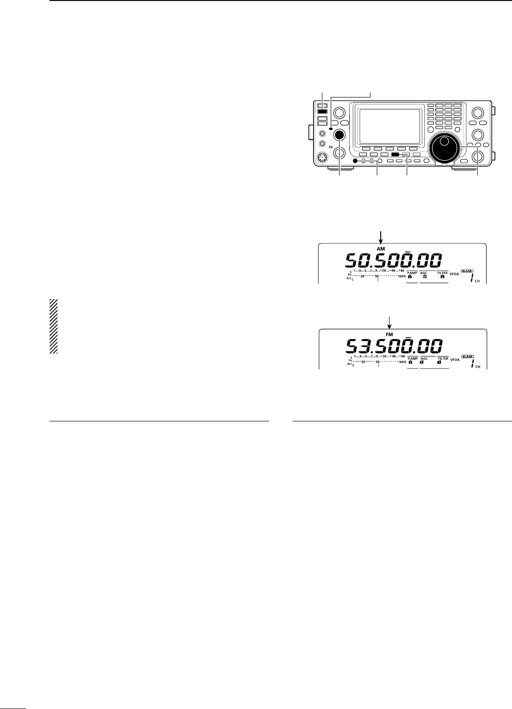
61
4RECEIVE AND TRANSMIT
N/PERATING!-&-
q Select the desired frequency band. (p. 35)
w Push [AM/FM] to select the AM or FM mode.
s!FTER!-OR&-ISSELECTEDHOLDDOWN;!-&-=FOR
second to select the data mode, if needed.
e Rotate [MAIN DIAL] to tune a desired signal.
s4HE3METERDISPLAYSTHERECEIVEDSIGNALSTRENGTH
s
The tuning step can be changed in the tuning step pro-
gram mode. (p. 38)
r Rotate [AF] (MAIN Band) to adjust the audio to a
comfortable listening level.
t Push [PTT] on the microphone to transmit. (or
[TRANSMIT] on the transceiver)
s4HE4828INDICATOR-!)."ANDLIGHTSRED
y Speak into the microphone at your normal voice
level.
s2OTATE;-)#'!).=TOADJUSTTHEMICROPHONEGAININTHIS
step, if necessary.
u Release [PTT] to receive. (or push [TRANSMIT]
again)
NOTE:
s)NTHE!-MODEYOU CAN TRANSMITONONLYTHE
HF/50MHz frequency bands.
s4HE!-MODECANNOTBESELECTEDON THE
MHz frequency band.
[TRANSMIT] TX/RX indicator (MAIN Band)
[MIC GAIN] [AM/FM] [MAIN DIAL][AF]
(MAIN Band)
Appears
#ONVENIENT2ECEIVEFUNCTIONS
s0REAMPANDATTENUATORP
s4WIN0"4PASSBANDTUNINGP
s!'#AUTOGAINCONTROLP
s.OISEBLANKERP
s.OISEREDUCTIONP
s.OTCHlLTERP
s63#VOICESQUELCHCONTROLP
*AM only
#ONVENIENTFUNCTIONSFORTRANSMIT
s3PEECHCOMPRESSORP
s6/8VOICEOPERATEDTRANSMITP
s4ONECONTROLP
s4RANSMITQUALITYMONITORP
s AM mode
s FM mode
Appears
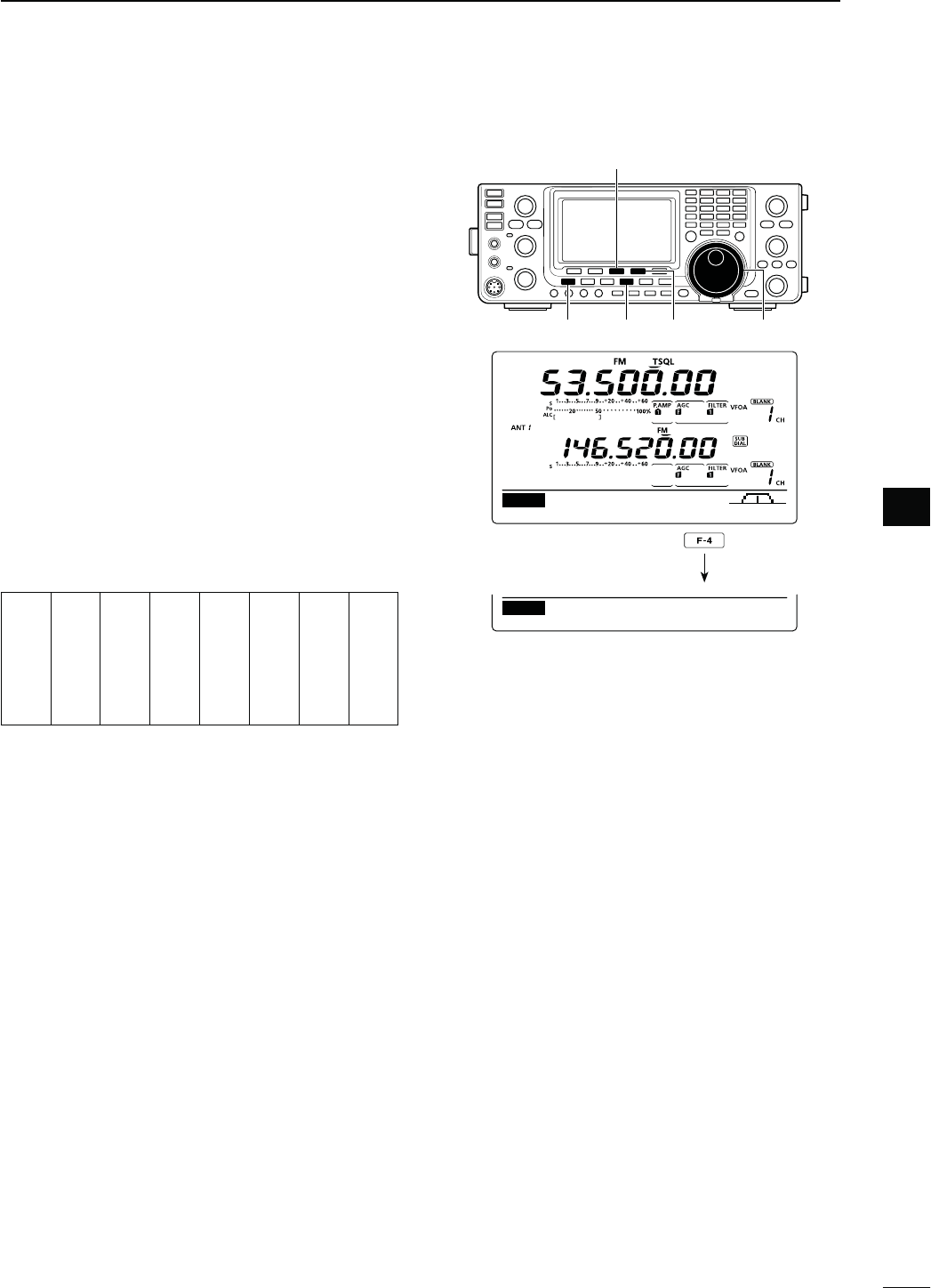
62
4
RECEIVE AND TRANSMIT
4
N4ONESQUELCHOPERATION
The tone squelch opens only when you receive a sig-
NAL CONTAINING A MATCHING SUBAUDIBLE TONE 9OU CAN
silently wait for calls from others using the same tone.
q
Push [AM/FM]
once or twice
to select the FM
mode.
w
P
ush [MENU] to display the “M1” screen (Menu 1).
e Push [TON](F-4) one or more times to turn ON the
Tone squelch function.
sh431,vAPPEARS
r Hold down [TON](F-4) for 1 second to display the
“TON” screen.
sh431,4ONEvAPPEARSONTHEFUNCTIONDISPLAY
t Rotate [MAIN DIAL] to select the desired tone
squelch frequency. (See the table shown below.)
s(OLDDOWN;&=FORSECONDTORESETTOTHEDEFAULTSET-
ting, if desired.
y Push [MENU] to save, and exit the “TON” screen.
u Communicate in the usual manner.
s!VAILABLETONESQUELCHFREQUENCIES (Unit: Hz)
67.0
69.3
71.9
74.4
77.0
79.7
82.5
85.4
88.5
91.5
94.8
97.4
100.0
103.5
107.2
110.9
114.8
118.8
123.0
127.3
131.8
136.5
141.3
146.2
151.4
156.7
159.8
162.2
165.5
167.9
171.3
173.8
177.3
179.9
183.5
186.2
189.9
192.8
196.6
199.5
203.5
206.5
210.7
218.1
225.7
229.1
233.6
241.8
250.3
254.1
[TON](F-4)
[F-3]
[AM/FM] [MAIN DIAL][MENU]
DUPAGC AFC TON SCP
M1
TON
SCANTON 88.5Hz
TSQL Tone
Hold down
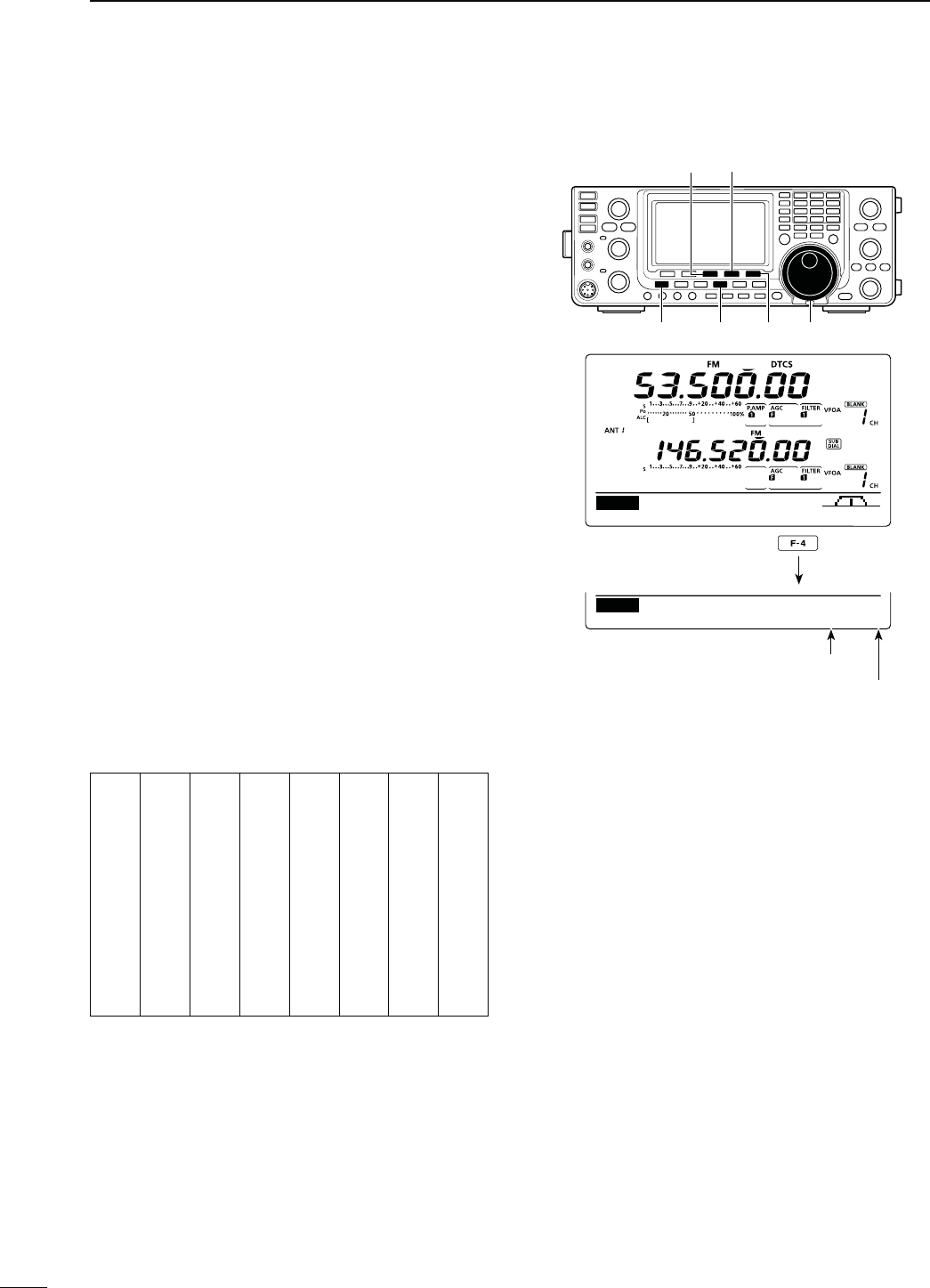
63
4RECEIVE AND TRANSMIT
N$4#3OPERATION
The DTCS function is another method of communica-
tions using selective calling. Only received signals hav-
ing a matching 3-digit code will open the squelch.
q
Push [AM/FM]
once or twice
to select the FM
mode.
w
P
ush [MENU] to display the “M1” screen (Menu 1).
e Push [TON](F-4) one or more times to turn ON the
DTCS function.
sh$4#3vAPPEARS
r Hold down [TON](F-4) for 1 second to display the
“TON” screen.
sh$4#3#ODEvAPPEARSONTHEFUNCTIONDISPLAY
t Rotate [MAIN DIAL] to select the desired DTCS
code number, and push [F-5] to select the desired
code polarity.
NN : Normal polarity is used for both transmit and
receive.
NR : Normal polarity is used for transmit, reversed
polarity is used for receive.
RN : Reversed polarity is used for transmit, normal
polarity is used for receive.
RR : Reversed polarity is used for both transmit
and receive.
s(OLDDOWN;&=FORSECONDTORESETTOTHEDEFAULTSET-
ting, if desired.
y Push [MENU] to save, and exit the “TON” screen.
u Communicate in the usual manner.
s!VAILABLE$4#3CODES
023
025
026
031
032
036
043
047
051
053
054
065
071
072
073
074
114
115
116
122
125
131
132
134
143
145
152
155
156
162
165
172
174
205
212
223
225
226
243
244
245
246
251
252
255
261
263
265
266
271
274
306
311
315
325
331
332
343
346
351
356
364
365
371
411
412
413
423
431
432
445
446
452
454
455
462
464
465
466
503
506
516
523
526
532
546
565
606
612
624
627
631
632
654
662
664
703
712
723
731
732
734
743
754
[F-5]
[TON](F-4)[F-3]
[AM/FM] [MAIN DIAL][MENU]
DUPAGC AFC TON SCP
M1
TON
SCANTON 023–NN
DTCS Code
Hold down
DTCS Code
DTCS code polarity
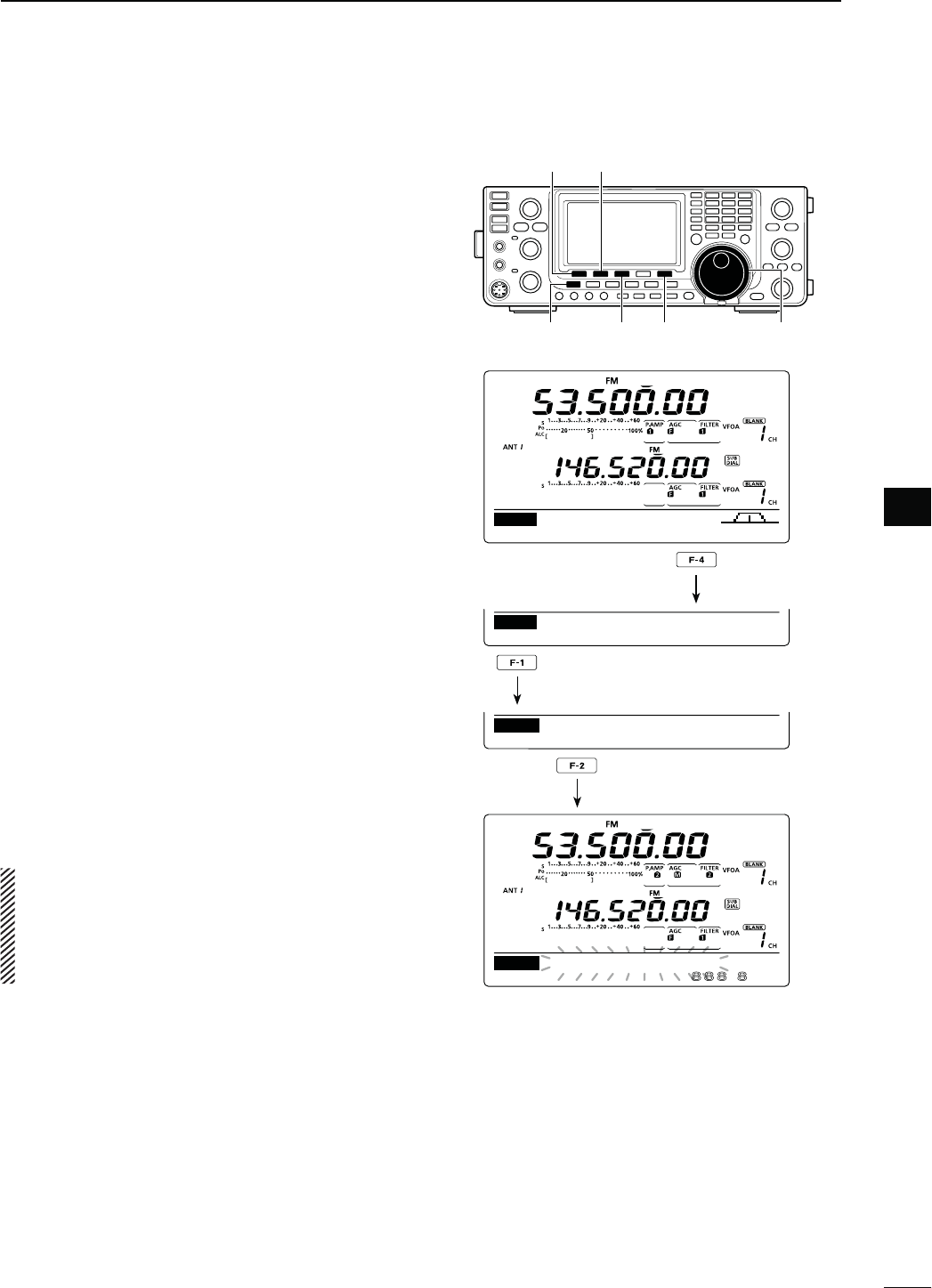
64
4
RECEIVE AND TRANSMIT
4
To search for a repeater’s sub-audible tone frequency,
a tone scan is available.
By monitoring a repeater signal with a tone squelch or
DTCS, you can determine the tone frequency neces-
sary to open the repeater or the squelch.
q
In the FM mode, p
ush [MENU] to display the “M1”
screen (Menu 1).
w Hold down [TON](F-4) for 1 second to enter the
“TON” screen.
e Push [TON](F-1) one or more times to select the
tone type to be scanned.
sh2PTR4ONEvFORAREPEATERTONEh431,4ONEvFORTONE
squelch or “DTCS Code” for a DTCS code can be se-
lected.
s7HENSELECTINGA$4#3CODETOBESCANNEDTHE$4#3
CODEANDITSPOLARITYISDISPLAYED9OUCANSELECTTHEDE-
sired polarity by pushing [F-5].
“NN” : Normal polarity for both transmit and receive.
“NR” : Normal polarity for transmit and reverse polarity
for receive.
“RN” : Reverse polarity for transmit and normal polarity
for receive.
“RR” : Reverse polarity for both transmit and receive.
r Push [SCAN](F-2) to start the Tone scan.
sh2PTR4ONE3#!.vh431,4ONE3#!.vORh$4#3#ODE
SCAN” blinks, depending on the type you selected.
s)F
“Up/Down” is selected as
the “MAIN DIAL (SCAN)”
option
in the Scan Set mode, rotating [MAIN DIAL]
changes the scanning direction. (p. 147)
t When a matched tone or code is found, the scan
pauses, and the detected sub-audible tone fre-
quency or DTCS code is set.
s(OLDDOWN;&=FORSECONDTORESETTOTHEDEFAULTSET-
ting, if desired.
y Push [SCAN](F-2) to cancel the Tone scan.
When the tone scan or DTCS code scan is used in
the Memory or Call channel mode, the detected
tone frequency or code can be used temporarily.
To save the detected tone frequency or code set-
ting, you must over-write the Memory or Call chan-
nel data. (pp. 140, 141)
N4ONESCAN$4#3CODESCANOPERATION
DUPAGC AFC TON SCP
M1
TON
SCANTON 88.5Hz
Rptr Tone
Hold down
Push to select the tone type.
Push to start or cancel the scan.
[TON] [SCAN]
[F-5]
[MENU] [F3] [MAIN DIAL]
.Hz
SCAN
TSQL
Tone SACN
TON
88.5Hz
TON SCAN
TON
TSQL
Tone
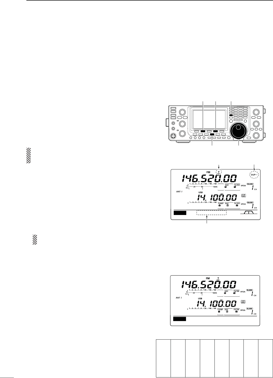
65
4RECEIVE AND TRANSMIT
2EPEATEROPERATION
A repeater receives transmitted signals and re-trans-
mits them on a different frequency. When using a re-
peater, the transmit frequency is shifted from the re-
ceive frequency by a frequency offset.
A repeater can be accessed using the duplex opera-
tion to set the frequency shift to the same value as the
repeater’s frequency offset.
See page 94 for details on accessing a D-STAR®
repeater.
q Select the desired frequency band. (p. 35)
w Push [VFO/MEMO] to select the VFO mode.
e Push [A/B] to select VFO A.
r Push [AM/FM] to select the FM mode.
t R
otate
[MAIN DIAL] to set the receive frequency
(repeater output frequency).
When the auto repeater function is turned ON (avail-
able in only the U.S.A. and Korea versions), steps
y and u are not necessary. (p. 67)
y
P
ush [MENU] to display the “M1” screen (Menu 1),
then push [DUP](F-2) one or more times to set the
offset direction.
sh$50nvORh$50vAPPEARS
s4HETRANSMITFREQUENCYREPEATERINPUTFREQUENCYAP-
pears on the function dislay.
s4HEFREQUENCYOFFSETAMOUNTOFSHIFTCANBESETIN
the
“DUP Offset” item
of the Set mode. (p. 163)
u Push [TON](F-4) to turn ON the repeater tone.
sh4vAPPEARS
s4HETONEFREQUENCYCANBESETIN
the
“TON” screen. 88.5
Hz is set by default. (p. 62)
NOTE: To transmit a 1750 Hz European repeater
tone, hold down [TON](F-4) while transmitting.
u Communicate in the normal way.
[AM/FM]
[A/B][TON][DUP]
[MAIN DIAL]
M1
DUPAGC AFC TON SCP
145.92000
Appears Appears
Appears
D2EPEATERACCESSTONEFREQUENCYSETTING
Some repeaters require a subaudible tone to be ac-
cessed. Subaudible tones are superimposed on your
NORMALSIGNALANDMUSTBESETlRST9OUCANSELECT
tones from 67.0 Hz to 254.1 Hz.
q
In the FM mode, p
ush [MENU] to display the “M1”
screen (Menu 1).
w Push [TON](F-4) one or more times to turn ON the
tone encoder function.
sh4vAPPEARS
e Hold down [TON](F-4) for 1 second to display the
“TON” screen.
sh2PTR4ONEvAPPEARSONTHEFUNCTIONDISPLAY
r Rotate [MAIN DIAL] to select the desired repeater
tone frequency. (See the table to the right.)
t Push [MENU] to save, and exit the “TON” screen.
s!VAILABLETONEFREQUENCIES (unit: Hz)
67.0
69.3
71.9
74.4
77.0
79.7
82.5
85.4
88.5
91.5
94.8
97.4
100.0
103.5
107.2
110.9
114.8
118.8
123.0
127.3
131.8
136.5
141.3
146.2
151.4
156.7
159.8
162.2
165.5
167.9
171.3
173.8
177.3
179.9
183.5
186.2
189.9
192.8
196.6
199.5
203.5
206.5
210.7
218.1
225.7
229.1
233.6
241.8
250.3
254.1
TON
SCANTON 88.5Hz
Rptr Tone
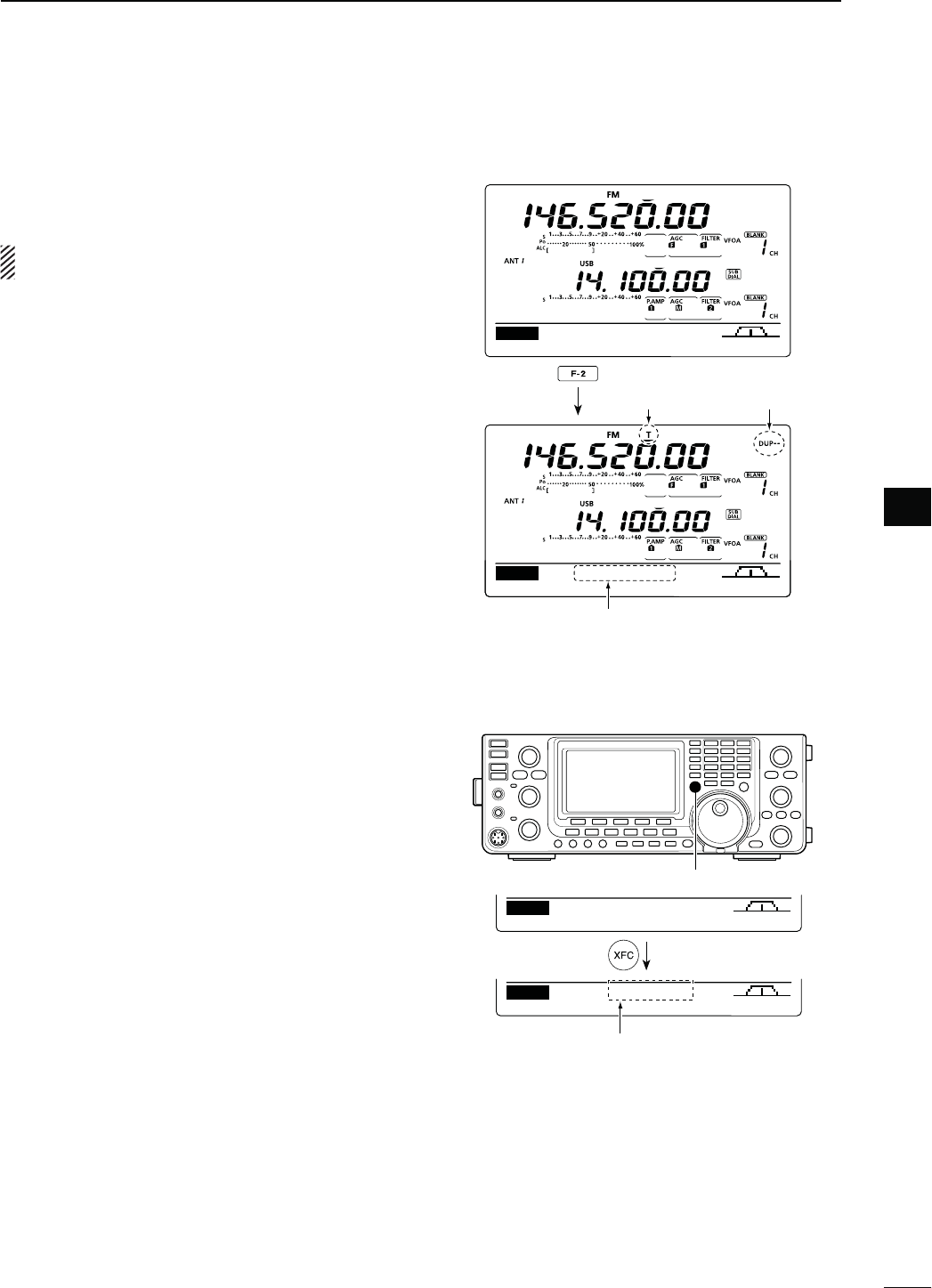
66
4
RECEIVE AND TRANSMIT
4
D/NETOUCHREPEATERFUNCTION
This function allows you to set the repeater operation
by holding down one switch.
First, set the frequency offset as well as the repeater
access tone frequency (p. 163).
q Select the desired frequency band. (p. 35)
w
In the FM mode, p
ush [A/B] to select VFO A.
e
Rotate
[MAIN DIAL] to set the desired receive fre-
quency (repeater output frequency).
r
P
ush [MENU] to display the “M1” screen (Menu 1).
t Hold down [DUP](F-2) for 1 second to turn ON the
One-touch repeater function.
sh4vANDh$50nvAPPEARS
s4HEREPEATERRECEIVEFREQUENCYAPPEARSONBOTTOMOF
the function display.
s4HE3PLITFREQUENCYOPERATIONISAUTOMATICALLYTURNED
OFF, if it is ON.
y Push [DUP](F-2) once or twice to switch the offset
direction.
sh$50nvORh$50vAPPEARS
u Communicate in the normal way.
DUPAGC AFC TON SCP
M1
M1
DUPAGC AFC TON SCP
145.92000
Appears Appears
Transmit (repeater receive)
frequency appears
Hold down
D4RANSMITFREQUENCYMONITORCHECK
9OUMAYBEABLETODIRECTLYRECEIVETHEOTHERPARTYS
transmitted signal without having to go through a re-
peater. This function helps you to check whether the
direct communication can be done, or not.
± While receiving, hold down [XFC] to see if you can
directly receive the other party’s transmitted signal.
s7HILEHOLDINGDOWN;8&#=THEOFFSETDIRECTIONANDFRE-
quency offset are displayed on the function display.
AGC DUP AFC TON SCP
M1
–600.0k
DUPAGC AFC TON SCP
145.92000
M1
[XFC]
Frequency Offset direction and value.
Hold down
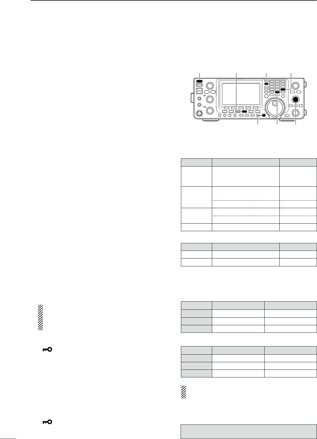
67
4RECEIVE AND TRANSMIT
Repeater operation (Continued)
D 3ETTINGTHE!UTO2EPEATERRANGES
53!AND+OREAVERSIONSONLY
The transceiver has three Auto Repeater ranges that
can be used for each frequency band. And you can set
the desired Auto Repeater ranges by programming the
lower and higher edge frequencies into the allowable
Memory channel of each band as described below.
q Select the desired frequency band. (p. 35)
w
Push [AM/FM]
once or twice
to select the FM
mode.
e
S
et the desired lower edge frequency.
r Turn ON the duplex operation, then select the du-
plex direction. (pp. 65, 163)
sh$50nvORh$50vISDISPLAYEDWHENTHEDUPLEXIS/.
s"OTHONETOUCHREPEATERANDMANUALREPEATERSETTINGS
are available.
t Rotate [M-CH] to select a Memory channel of the
selected frequency band.
s3EETHE-EMORYCHANNELCOMBINATIONLISTTOTHERIGHT
If the HF band is selected in step q, and you want to set
Range 1, select Memory channel 1 for the lower edge
frequency programming.
y Hold down [MW] for 1 second to program the data
into the Memory channel.
sBEEPSSOUNDWHENTHEmemory programming is com-
plete.
u Set the upper edge frequency.
i Rotate [M-CH] to select the opposite Memory chan-
nel.
s3ELECT-EMORYCHANNELIF-EMORYCHANNELISSE-
lected in step t.
o Hold down [MW] for 1 second to program the data
into the selected Memory channel.
sBEEPSSOUNDWHENTHEmemory programming is com-
plete.
!0 Repeat steps q to o to program other ranges.
NOTE: We recommend that all repeater ranges
are programmed into the Memory channel of
each band. The previously programmed ranges
will be lost.
!1 Hold down [SPEECH/LOCK] for 1 second to turn
ON the Dial Lock function.
sh ” appears.
!2 Hold down [POWER] for 1 second to turn OFF the
power.
!3 While holding down [AM/FM] and [F-INP ENT],
push [POWER] to turn ON the power.
shΩ Auto Rptr Set ≈” appears.
s4HEPROGRAMMEDAUTOREPEATERRANGESARESET
s4HEMEMORYCHANNELSCANBEUSEDFORNORMALOPERATION
after programming.
!4 Hold down [SPEECH/LOCK] for 1 second to turn
OFF the Dial Lock function.
sh ” disappears.
s &REQUENCYRANGEANDSHIFTDIRECTION$EFAULT
53!VERSION
"AND &REQUENCYRANGE-(Z
3HIFTDIRECTION
-(Z
51.620000 – 51.999999
52.500000 – 52.999999
53.500000 – 53.999999
“DUP–”
-(Z
145.200000 – 145.999999
146.610000 – 146.999999 “DUP–”
147.000000 – 147.399999 “DUP+”
-(Z 442.000000 – 444.999999 “DUP+”
447.000000 – 449.999999 “DUP–”
-(Z 1282.000000 – 1295.000000 “DUP–”
+OREAVERSION
"AND &REQUENCYRANGE-(Z
3HIFTDIRECTION
-(Z 439.000000 – 440.000000 “DUP–”
-(Z 1290.000000 – 1293.000000 “DUP–”
s -EMORYCHANNELCOMBINATIONOFTHE!UTO2E-
PEATERRANGES
&REQUENCYBAND(&-(Z
,OWERFREQUENCY (IGHERFREQUENCY
2ANGE Memory CH 1 Memory CH 2
2ANGE Memory CH 3 Memory CH 4
2ANGE Memory CH 5 Memory CH 6
&REQUENCYBAND-(Z
,OWERFREQUENCY (IGHERFREQUENCY
2ANGE Memory CH 7 Memory CH 8
2ANGE Memory CH 9 Memory CH 10
2ANGE Memory CH 11 Memory CH 12
NOTE: Auto Repeater ranges must be programmed
into the Memory channel of EACH band.
[SPEECH/LOCK]
[AM/FM] [BAND](MAIN/SUB)[POWER]
[M-CH]
[F-INP ENT]
[MW]
The optional UX-9100 is required for 1200 MHz frequency
band operation.
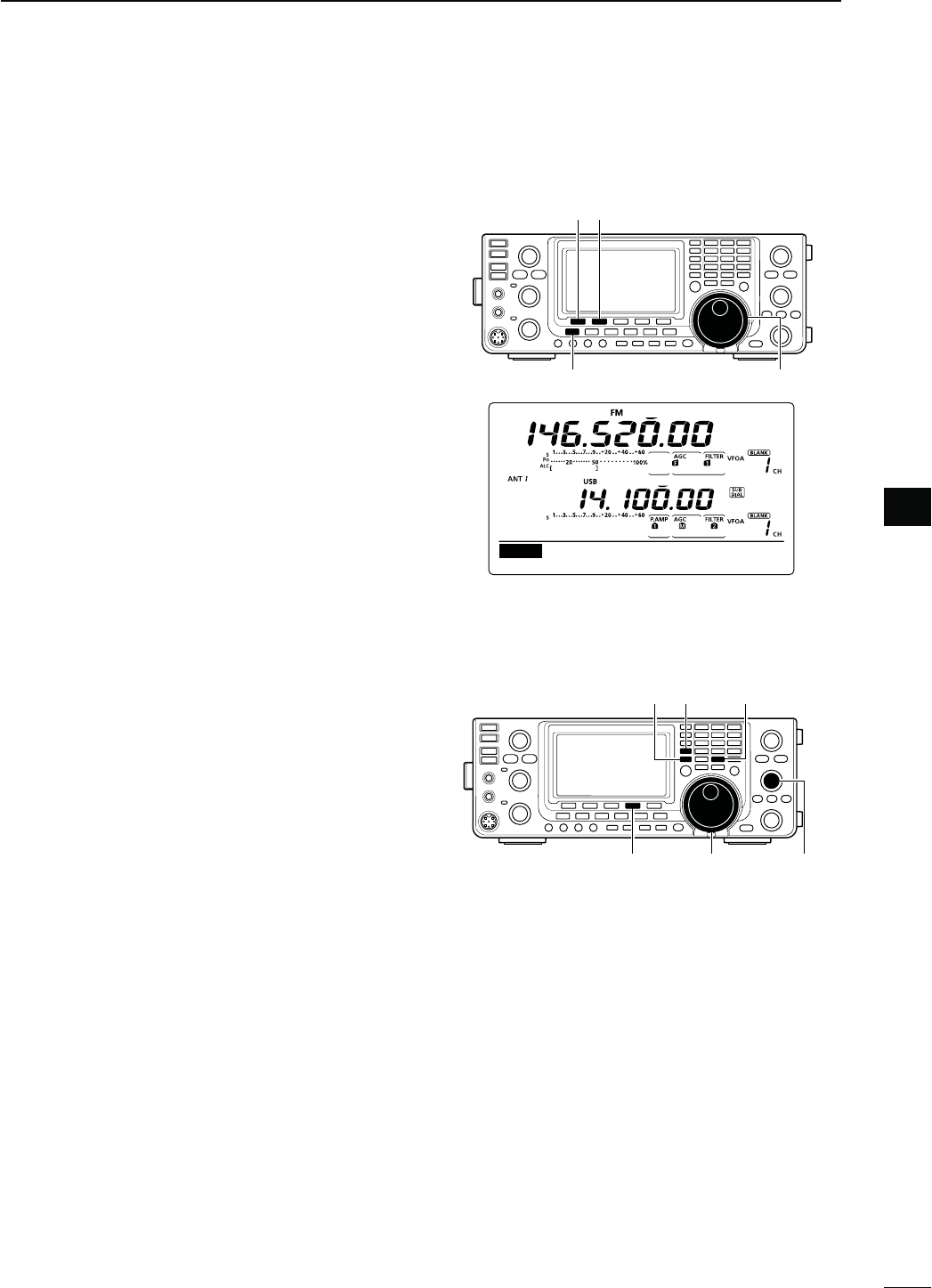
68
4
RECEIVE AND TRANSMIT
4
D 4URNING/.THE!UTO2EPEATERFUNCTION
53!AND+OREAVERSIONSONLY
When the operating frequency falls within the repeater
output frequency range, the Auto Repeater function
automatically sets the repeater settings (duplex ON/
OFF, duplex direction, tone encoder ON/OFF).
q Hold down [MENU] for 1 second to enter the Set
mode.
w Push [Y](F-1) or [Z](F-2) to select “Auto Re-
peater.”
e Rotate [MAIN DIAL] to turn ON the Auto Repeater
function.
53!VERSION
sh/.nv!CTIVATESDUPLEXONLY
sh/.nv!CTIVATESDUPLEXANDTONE
sh/&&v!UTOREPEATERFUNCTIONISTURNED/&&
+OREAVERSION
sh/.v!CTIVATESDUPLEXANDTONE
sh/&&v!UTOREPEATERFUNCTIONISTURNED/&&
r Push [MENU] to save, and exit the Set mode.
[][]
[MAIN DIAL][MENU]
ON–1 (default for the U.S.A. version)
Ù
20
ÚON–1
SET Auto Repeater
D3TORINGANONSTANDARDREPEATER
q Turn OFF the Auto Repeater function in the Set
mode. (p. 163)
w Push [A/B] to select VFO A.
e Rotate [MAIN DIAL] to set the repeater output fre-
quency.
r Push [A/B] to select VFO B.
t Rotate [MAIN DIAL] to set the repeater input fre-
quency.
y Push [A/B] to select VFO A.
u Push [SPLIT] to turn ON the Split function.
i Push [TON](F-4) to turn ON the previously set tone
encoder.
o Rotate [M-CH] to select the desired memory chan-
nel.
sh",!.+vAPPEARSWHENABLANKCHANNELISSELECTED
!0 Hold down [MW] for 1 second to store the set con-
tents into the selected memory channel.
[TON] [MAIN DIAL] [M-CH]
[SPLIT][A/B] [MW]
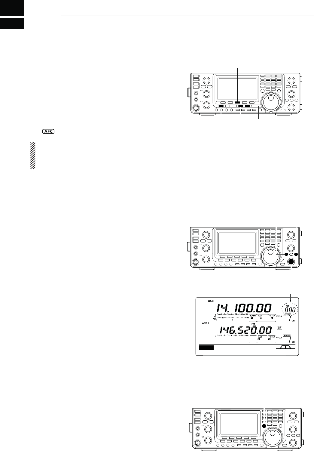
5
69
FUNCTIONS FOR RECEIVE
N!&#OPERATION
(Mode: FM/DV
AFC stands for Automatic Frequency Control. The AFC
function tunes the displayed frequency automatically
when an off-center frequency is received.
q
Push [AM/FM]
or
;$6s$2=
once or twice
to select
the FM or DV mode.
w
P
ush [MENU] to display the “M1” screen (Menu 1).
e Push [AFC](F-3) to turn ON the AFC function.
sh” appears when the AFC function is ON.
The AFC limit can be set in the Set mode. (p. 164)
While the AFC limit is ON, AFC stops tuning when
the received frequency exits the frequency limit
range.
The optional UT-121 is required for DV mode operation.
[AFC]
[AM/FM] [D[MENU]
N2)4FUNCTION
The RIT (Receive Increment Tuning) function com-
pensates for off-frequency operation of the received
station.
The function shifts the receive frequency up to
±9.99 kHz in 10 Hz steps*, without changing the trans-
mit frequency.
* The [RIT/∂TX] control tunes in 1 Hz steps when the op-
erating frequency readout is set to the 1 Hz step readout.
However, the 1 Hz digit is not displayed on the frequency
shift readout.
q Push [RIT] to turn ON the RIT function.
sh2)4vANDTHEFREQUENCYSHIFTAPPEARWHENTHISFUNCTION
is ON.
w Rotate the [RIT/∂TX] control.
s(OLDDOWN;#,%!2=FORSECONDTORESETTHE2)4FRE-
quency.
s0USH;#,%!2=MOMENTARILYTORESETTHE2)4FREQUENCY
when the quick RIT clear function is ON. (p. 164)
s(OLDDOWN;2)4=FORSECONDTOADDTHEFREQUENCYSHIFT
to the operating frequency.
e To cancel the RIT function, push [RIT] again.
sh2)4vANDTHEFREQUENCYSHIFTDISAPPEAR
D2)4MONITORFUNCTION
When the RIT function is ON, holding down [XFC] al-
lows you to listen to the displayed frequency (RIT is
temporarily cancelled).
[RIT] [CLEAR]
[RIT/∂TX] control
DUPAGC COMP TBW SCP
M1
Appear
[XFC]
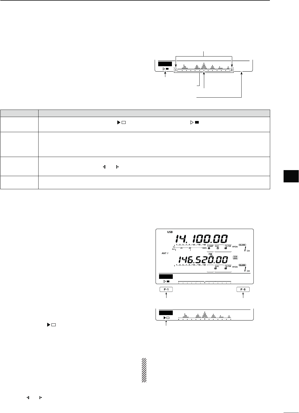
70
5
FUNCTIONS FOR RECEIVE
5
N3IMPLEBANDSCOPE
The Band Scope function allows you to visually check
the location and strength of signals around a specified
frequency.
The IC-9100’s Band Scope function can be used in
any operating mode and any frequency band.
INDICATOR DESCRIPTION
3WEEPICON While the band scope is sweeping, “ vISDISPLAYEDWHILESTOPPEDh ” is displayed.
2ECEIVEDAUDIOISNOTHEARDFROMTHESPEAKERWHILETHEBANDSCOPEISSWEEPING
"ANDSCOPE
DISPLAY
Displays the signal location and strength in relation to the center (displayed) frequency. Signal strength is
relative to the S-meter level, S1 to S9, with each vertical dot in the band scope indicator equal to one seg-
ment of the S-meter. Signal activity is measured ±30 steps from the center frequency, with each step equal
to the selected sweep step.
&REQUENCY
DISPLAYMARK
After a sweep, displays the relative position of the reference frequency. When the reference frequency is
outside of the sweep range, “ ” or “ ” blinks. After changing the frequency, hold down [F-3] for 1 second to
automatically return to the center frequency.
3WEEPSTEP
DISPLAY
Displays the selected sweep step. 0.5, 1, 2, 5, 10, 20 and 25 kHz are selectable. Each dot of the band scope
display is approximately equal to the selected sweep step.
The band scope measures receive signal location
and strength over a specified range on either side of
a selected frequency, in either the VFO or memory
modes.
q Rotate [MAIN DIAL] to select a frequency.
w
P
ush [MENU] to display the “M1” screen (Menu 1),
then push [SCP](F-5) to display the “SCP” screen
(Band Scope).
s!UTOMATICALLYSTARTSSWEEPINGWITHTHEPREVIOUSLYSE-
lected sweeping step.
s$URINGASWEEPRECEIVEDSIGNALSCANNOTBEHEARD
e Push [F-5] one or more times to select the desired
sweep step.
s
0.5, 1, 2, 5, 10, 20 and 25 kHz are selectable.
r Push [F-1] to start sweeping, then automatically
stop after sweeping.
s(OLDDOWN;&=FORSECONDTOSTARTCONTINUOUSSWEEP-
ing. In this case, push [F-1] again to stop the sweeping.
s$URINGASWEEPh ” is displayed and received signals
cannot be heard.
s)FTHEREISALOTOFSIGNALNOISETURN/&&THE0REAMPLIFER
to reduce the signal input level, and turn ON the Attenu-
ator to improve the readability of the band scope.
t Rotate [MAIN DIAL] to find a signal that you wish to
communicate with. If you find the signal, communi-
cate in the normal way.
s)FYOUWANTTORETURNTOTHEFREQUENCYYOUWEREUSING
before rotating [MAIN DIAL], hold down [F-3] for 1 sec-
ond.
s)FTHESELECTEDFREQUENCYISSETOUTSIDEOFTHESWEEPED
range, “ ” or “ ” blinks.
y If you want to update the band conditions while re-
ceiving, repeat steps e and r.
SCP
0.5k
STEP
Sweep step display
Sweep icon
Band scope display
Frequency display mark
SCP
0.5k
STEP
SCP
0.5k
STEP
Sweep start/stop Sweep step selection
Sweep icon
Blinks when the reference frequency
is outside of the sweep range.
NOTE:
If you select a large sweep step, a wide frequency
range can be displayed on the band scope, but
some signals may be skipped and not displayed.
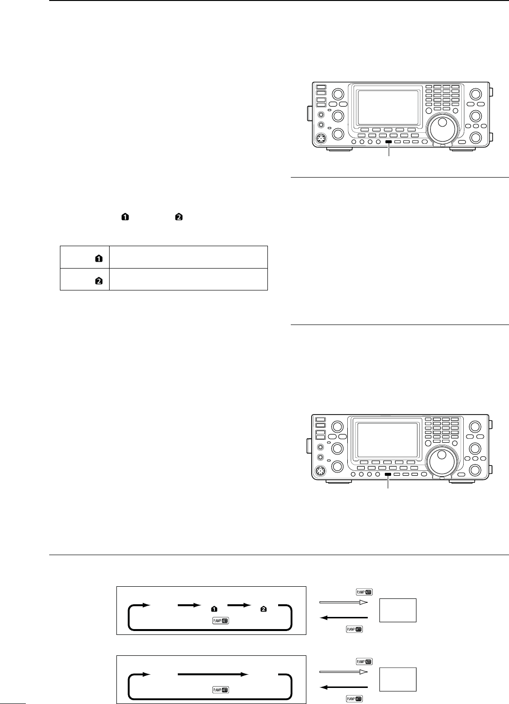
71
5FUNCTIONS FOR RECEIVE
N0REAMPLIlER
The preamplifier amplifies weak signals in the receiver
front end, to improve the S/N ratio and sensitivity.
Turn this function ON when receiving weak signals.
The AG-25, AG-35 or AG-1200*1 pre-amplifier unit is
required for 144, 430 or 1200 MHz*2 frequency band.
s"ESURETOSETTHEh%840!-0vITEMFOREACHFREQUENCY
band in the Set mode. (pp. 165, 166)
&REQUENCYBAND(&-(Z
±0USH;0!-0s!44=ONEORMORETIMESTOSETTHEPRE-
amp OFF, preamp 1 ON or preamp 2 ON.
s%ITHERh0!-0 ” or “P. AMP ” is displayed when the
preamp 1 or preamp 2 is ON.
s.OINDICATORISDISPLAYEDWHENTHEPREAMPIS/&&
P. AMP Wide dynamic range preamplifier. It is most
effective for the 1.8 to 21 MHz bands.
P. AMP High-gain preamplifier. It is most effective
for the 24 to 50 MHz bands.
&REQUENCYBAND-(Z*2
±0USH;0!-0s!44=ONCEORTWICETOTURNANOPTIONAL
pre-amplifier unit ON or OFF, if installed.
sh0!-0vAPPEARSWHENTHEPREAMPLIlERUNITIS/.
s.OINDICATORISDISPLAYEDWHENTHEPREAMPLIlERUNITIS
OFF.
N!TTENUATOR
The attenuator prevents a desired signal from being
distorted when very strong signals are near the signal’s
frequency, or when very strong electromagnetic fields,
such as from broadcast stations are near your location.
These can both be independently set for each band.
±
Hold down [P.AMP/ATT] for 1 second to turn ON the
Attenuator.
sh!44vAPPEARSONTHEDISPLAYWHENTHE!TTENUATORIS
ON.
± Push [P.AMP/ATT] momentarily to turn it OFF.
[PTT]
About the “P.AMP2” preamplifier
The preamp 2 is a high gain receive amplifier. When
it is used in the presence of strong electromagnetic
fields, distortion sometimes results. In such cases, use
either the “P.AMP 1” or “P.AMP OFF” setting.
Preamp 2 is most effective when:
s5SEDONBANDSABOVE-(ZANDWHENSIGNALSARE
weak.
s2ECEIVESENSITIVITYISINSUFlCIENTWHENUSINGLOWGAIN
antennas, or while using a narrow band antenna.
(such as small loop, a Beverage antenna or a short
9AGIANTENNA
*1
AG-1200 has been discontinued, but it can be still be
used.
*2 The optional UX-9100 is required for 1200 MHz frequency
band operation.
!BOUTTHE0REAMPLIlERAND!TTENUATORSWITCHINGPROCEDURE
The Preamplifier and Attenuator are switched with [P.AMP/ATT], as shown below.
Hold down
Push
ATT ON
Push
P.AMP
OFF
P.AMP
ON
Push
ATT ON
Hold down
Push
P.AMP
OFF
P.AMP P.AMP
s(&-(ZFREQUENCYBANDS
s-(ZFREQUENCYBANDS
[PTT]
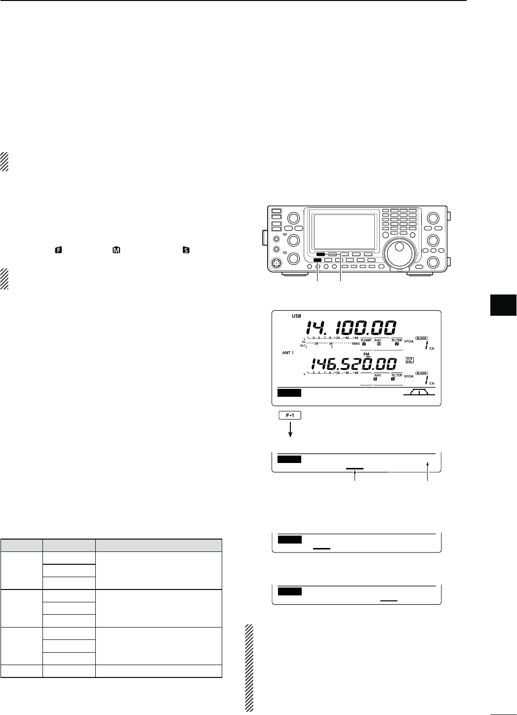
72
5
FUNCTIONS FOR RECEIVE
5
N!'#FUNCTION
The AGC (Auto Gain Control) controls receiver gain to
produce a constant audio output level, even when the
received signal strength varies greatly.
The transceiver has 3 pre-set AGC time constants: fast,
MIDANDSLOWFOR33"#72449AND!-MODES
In the FM and DV modes, the AGC time constant is
fixed as “FAST” (0.1 second).
D!'#SPEEDSELECTION
q3ELECTEITHERTHE33"#72449OR!-MODE
(p. 43)
w
Push [MENU] to display the “M1” screen (Menu 1),
then push [AGC](F-1) one or more times to select
AGC fast ( ), AGC mid ( ) or AGC slow ( ).
“AGC OFF” appears when the selected AGC
speed’s time constant is set to OFF.
D3ETTINGTHE!'#TIMECONSTANT
q3ELECTEITHERTHE33"#72449OR!-MODE
(p. 43)
w Push [MENU] to display the “M1” screen (Menu 1),
then hold down [AGC](F-1) for 1 second to display
the “AGC” screen.
e Push either [FAST](F-2), [MID](F-3) or [SLOW](F-4)
to select the desired AGC speed to be set.
s
An underline appears below the time constant display.
r Rotate [MAIN DIAL] to set the desired time con-
stant.
s!'#TIMECONSTANTCANBESETTOBETWEENTO
seconds (depending on the mode) or turned OFF.
s(OLDDOWN;&!34=&, [MID](F-3) or [SLOW](F-4) for
1 second to reset to the default setting for the selected
time constant, if desired.
t Select another mode (except for FM and DV), then
repeat steps e and r, if desired.
y Push [MENU] to save, and exit the “AGC” screen.
s3ELECTABLE!'#TIMECONSTANT (unit: seconds)
Mode $EFAULT 3ELECTABLE!'#TIMECONSTANT
SSB
0.3 (FAST)
OFF, 0.1, 0.2, 0.3, 0.5, 0.8, 1.2,
1.6
, 2.0, 2.5, 3.0, 4.0, 5.0, 6.0
2.0 (MID)
6.0 (SLOW)
#72449
0.1 (FAST)
OFF, 0.1, 0.2, 0.3, 0.5, 0.8, 1.2,
1.6
, 2.0, 2.5, 3.0, 4.0, 5.0, 6.0
0.5 (MID)
1.2 (SLOW)
AM
3.0 (FAST)
OFF, 0.3, 0.5, 0.8, 1.2, 1.6
, 2.0,
2.5, 3.0, 4.0, 5.0, 6.0, 7.0, 8.0
5.0 (MID)
7.0 (SLOW)
FM/DV 0.1 (FAST) Fixed
[MENU] [AGC]
Appears under the selected AGC
speed’s time constant display.
Selected mode
DUPAGC COMP TBW SCP
M1
0.3s 2.0s 6.0s
FAST MID SLOW SSB
AGC
s7HEN!'#FASTISSELECTED
0.3s 2.0s 6.0s
FAST MID SLOW SSB
AGC
s7HEN!'#SLOWISSELECTED
0.3s 2.0s 6.0s
FAST MID SLOW SSB
AGC
s7HEN!'#MEDIUMISSELECTED
Hold down
For your information
When you are receiving a weak signal, and a strong
signal is momentarily received, the AGC function
quickly reduces the receiver gain. When that sig-
nal disappears, the transceiver may not receive
the weak signal because of the AGC action. In that
case, hold down [AGC](F-1) for 1 second, and ro-
tate [MAIN DIAL] to set the time constant to OFF.
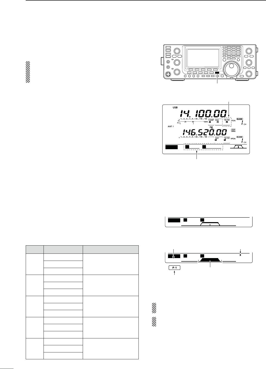
73
5FUNCTIONS FOR RECEIVE
N)&lLTERSELECTION
The transceiver has 3 passband width IF filters for
each mode.
The filter selection is automatically memorized in
each mode.
The PBT shift frequencies are automatically memo-
rized in each filter.
D)&lLTERSELECTION
q Select the desired mode.
w Push [FILTER] one or more times to select IF filter
1, 2 or 3.
s4HESELECTEDPASSBANDWIDTHANDlLTERNUMBERISDIS-
played on the LCD.
D&ILTERPASSBANDWIDTHSETTING
-ODE33"#72449!-
q Hold down [FILTER] for 1 second to display the “FIL”
screen (Filter) to set the filter passband width.
w3ELECTEITHERTHE33"#72449OR!-MODE
s0ASSBANDWIDTHSFOR&-AND$6MODESARElXEDAND
cannot be set.
e Push [FILTER] one or more times to select IF filter
1, 2 or 3.
r Push [BW](F-1), then rotate [MAIN DIAL] to adjust
the desired passband width.
Then push
[BW](F-1)
to
set it.
s7HILEHOLDINGDOWN;"7=&ROTATING;-!).$)!,=
also adjusts the passband width. After adjustment, re-
lease [BW](F-1) to set it.
s(OLDDOWN;&=FORSECONDTORESETTOTHEDEFAULTSET-
ting, if desired.
t Repeat steps w to r if desired.
y Push [MENU] to save, and exit the “FIL” screen.
Mode )&lLTER !DJUSTABLERANGESTEPS
SSB
FILTER1 (3.0 kHz)
50 to 500 Hz (50 Hz)
600 to 3600 Hz (100 Hz)
FILTER2 (2.4 kHz)
FILTER3 (1.8 kHz)
SSB-D
CW
FILTER1 (1.2 kHz)
50 to 500 Hz (50 Hz)
600 to 3600 Hz (100 Hz)
FILTER2 (500 Hz)
FILTER3 (250 Hz)
2449
FILTER1 (2.4 kHz)
50 to 500 Hz (50 Hz)
600 to 2700 Hz (100 Hz)
FILTER2 (500 Hz)
FILTER3 (250 Hz)
AM
AM-D
FILTER1 (9.0 kHz)
200 Hz to 10 kHz (200 Hz)
FILTER2 (6.0 kHz)
FILTER3 (3.0 kHz)
FM
FM-D
DV
FILTER1 (15 kHz)
Fixed
FILTER2 (10 kHz)
FILTER3 (7.0 kHz)
[FILTER]
DUPAGC COMP TBW SCP
M1
S
0
B
2.4K
The selected filter width is displayed
when [FILTER] is pushed.
Filter selection
Push [BW](F-1), then rotate [MAIN DIAL] to ad-
just the passband width. Then push [BW](F-1),
BW
SSB-2 2.4K
SHARP
FIL
S
0
B
2.4K
BW
SSB-2 2.4K
SHARP
FIL
S
0
B
2.4K
s“FIL” SCREENDISPLAY
s7HILEADJUSTINGTHEPASSBANDWIDTH
Appears
Reverses
Shows the selected filter and passband width.
The PBT shift frequencies are cleared when the
passband width is changed.
This “FIL” screen (Filter) graphically displays the
PBT shift frequencies and passband width.
Blinks
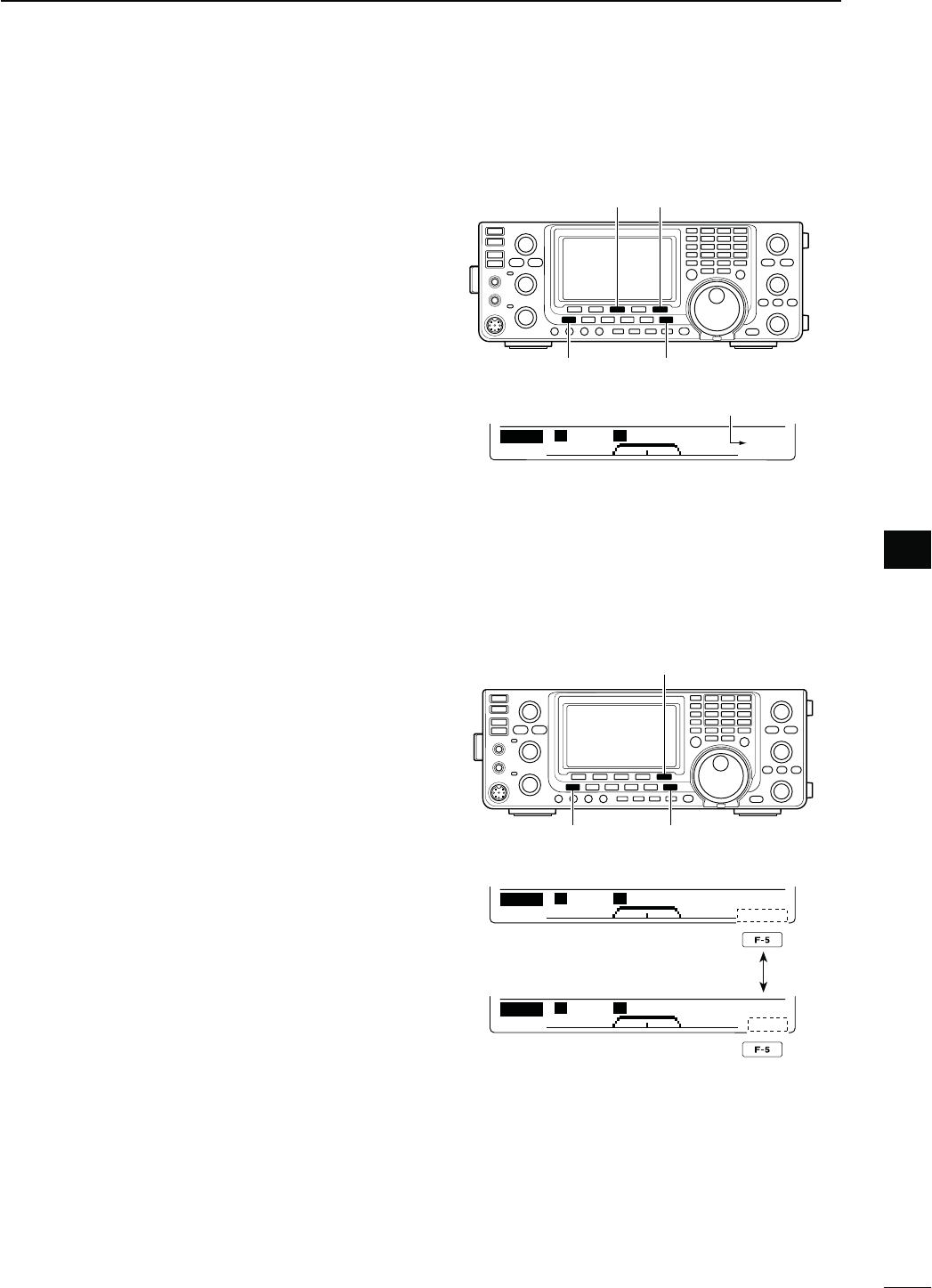
74
5
FUNCTIONS FOR RECEIVE
5
DST)&lLTERSELECTION
-ODE33"#72449!-
The IC-9100 has a 15 kHz filter passband width at the
1st IF frequency. The 1st IF filters reduce interference
from strong nearby signals.
If the optional FL-430 1ST IF FILTER (6 kHz) is installed,
a 6 kHz filter width can be used. Or, if the FL-431 1ST
IF FILTER (3 kHz) is installed, a 3 kHz filter width can be
used.
s4HElLTERPASSBANDWIDTHCANBESELECTEDONONLYTHE
HF/50 MHz band frequency.
q Hold down [FILTER] for 1 second to display the “FIL”
screen (Filter).
w3ELECT33"#72449OR!-MODE
s4HEPASSBANDWIDTHSFOR&-AND$6MODESARElXED
and have no options.
e Hold down [F-5] for 1 second to select the desired
filter width from 15 kHz, 6 kHz and 3 kHz.
s(OLDDOWN;&=FORSECONDTORESETTOTHEDEFAULTlLTER
setting, if desired.
(The filter passband width setting is
also reset to the default setting.)
r Push [MENU] to save, and exit the “FIL” screen.
D)&$30lLTERSHAPE
-ODE33"#7
A soft or sharp type of DSP filter shape for both SSB
and CW can be independently selected.
q Hold down [FILTER] for 1 second to display the “FIL”
screen (Filter).
w Select the SSB or CW mode.
e Push [F-5]
once or twice
to select either the soft or
sharp filter shape.
r Push [MENU] to save, and exit the “FIL” screen (Fil-
ter).
[MENU] [FILTER]
[F-5][F-3]
15 kHz is selected.
BW
SSB-2 2.4K
R:15K
SHARP
FIL
S
0
B
2.4K
[MENU] [FILTER]
[F-5]
BW
SSB-2 2.4K
SHARP
FIL
S
0
B
2.4K
BW
SSB-2 2.4K
SOFT
FIL
S
0
B
2.4K
Push
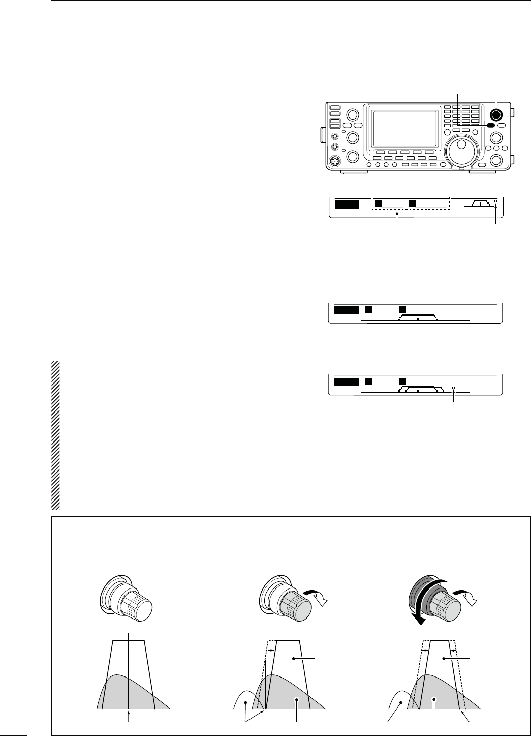
75
5FUNCTIONS FOR RECEIVE
N4WIN0"4OPERATION
-ODE33"#72449!-
To reject interference, PBT (Passband Tuning) elec-
tronically narrows the IF passband width by shifting the
IF frequency slightly outside of the IF filter passband.
The IC-9100 uses DSP for the PBT function. Moving
both [TWIN-PBT] controls shift the IF passband cen-
ter frequency both above and below the received fre-
quency.
± The LCD graphically shows the passband width and
frequency shift.
± Hold down [FILTER] for 1 second to display the “FIL”
screen (Filter). Current passband width and fre-
quency shift are displayed in the “FIL” screen.
± Hold down [PBT-CLR] for 1 second to set the IF
frequency to the center position.
s4HEhDOTvDISAPPEARS
The variable range depends on the passband width
and mode. The edge of the variable range is half of the
passband width. The PBT is adjustable in 25 Hz steps
INTHE33"#72449MODESAND(ZINTHE!-
mode.
s
The [TWIN-PBT] controls should normally be set
to the center positions when there is no interfer-
ence. The PBT setting should be cleared.
s7HEN THE 0"4 IS USED THE AUDIO TONE MAY
change.
s4HECONTROLSDONOTFUNCTIONINTHE&-AND$6
modes.
s7HILE ROTATING THE;47).0"4=CONTROLSNOISE
may occur. This comes from the DSP unit and
does not indicate an equipment malfunction.
s
Pushing [PBT-CLR] displays the filter passband
width and shift value for 1 seconds on the function
display.
0"4/0%2!4)/.%8!-0,%
[TWIN-PBT][PBT-CLR]
DUPAGC COMP TBW SCP
M1
S
+ 25
B
2.3K
Passband width and shift
value are displayed while
[TWIN PBT] is used.
Appears when pass-
band is shifted.
BW
SSB-2 2.4K
R:15K
SHARP
FIL
S
0
B
2.4K
BW
SSB-2 2.4K
R:15K
SHARP
FIL
S
+200
B
2.0K
sh&),v SCREEN&ILTERDISPLAY
s7HILEADJUSTIONGTHE0"4SETTING
Appears when the passband is shifted.
Shows the selected filter and passband width.
Both controls in the center
positions (or hold down
[PBT-CLR] for 1 second.)
Cutting the lower
passband edge
Cutting both lower and
higher passband edges
PBT2
PBT1
PBT2
PBT1
PBT2
PBT1
IF center frequency Interference Desired signal
Passband
Interference InterferenceDesired signal
Passband
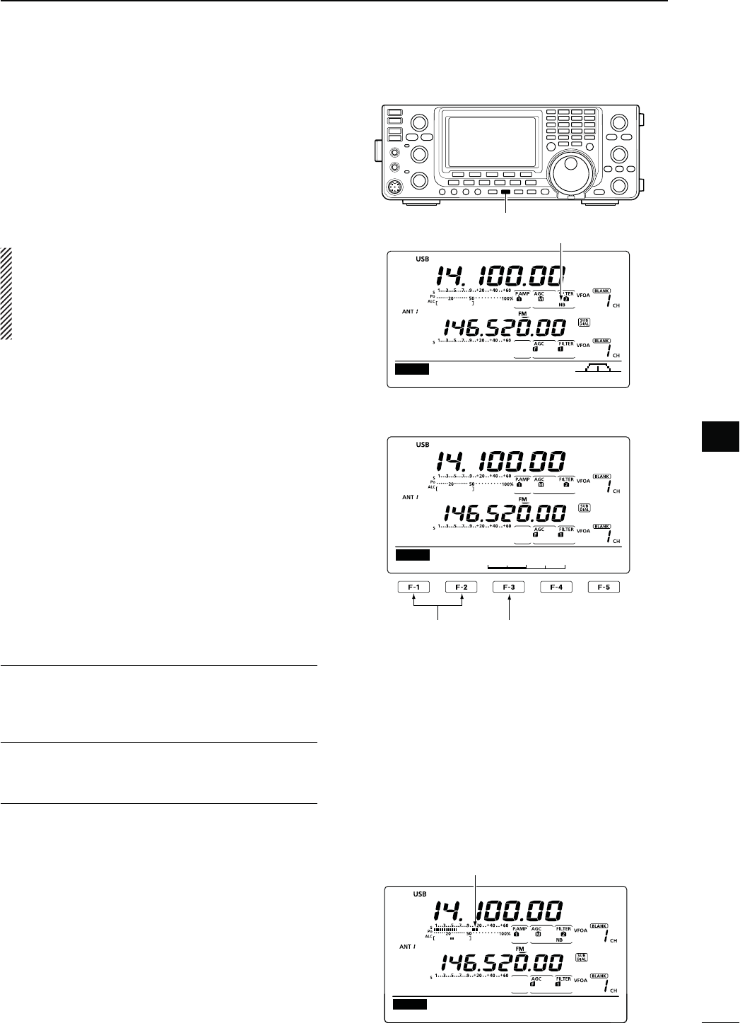
76
5
FUNCTIONS FOR RECEIVE
5
N.OISE"LANKER
-ODE33"#72449!-
The Noise Blanker eliminates pulse-type noise such
as noise from car ignitions.
± Push [NB] to turn the Noise Blanker function ON or
OFF.
s
“NB” is displayed when the
Noise Blanker
is ON.
When using the Noise Blanker function, received
signals may be distorted if they are excessively
strong or when used for noise other than pulses. In
this case, set the Noise Blanker threshold level to a
shallow position, or turn OFF the function. (see
below)
N-ETERPEAKHOLDFUNCTION
When the “Meter Peak Hold” item is set to ON in the
Set mode, the peak level of a received signal strength
or the output power is displayed for approximately 0.5
seconds. (p. 162)
D."3ETMODE
To deal with various types of noise, the attenuation
level and noise blanking duration can be set in the NB
set mode.
q Hold down [NB] for 1 second to display the “NB”
screen (Noise blanker).
w Push [Y](F-1) or [Z](F-2) to select the desired
item.
e Rotate [MAIN DIAL] to select the desired option.
s(OLDDOWN;&=FORSECONDTORESETTOTHEDEFAULTSET-
ting, if desired.
r Push [
NB
] to save, and
return to the previous
screen.
[NB]
DUPAGC COMP TBW SCP
M1
Appears
.",EVEL1. $EFAULT
3ETTHENOISEBLANKERTHRESHOLDLEVELTOBETWEEN
AND
."$EPTH2. $EFAULT
Set the noise attenuation level to between 1 and 10.
."7IDTH3. $EFAULT
Set the blanking duration to between 1 and 100.
1
50%
NB
NB Level
Select the item
Select a default
setting
Ù
11
ÚON
SET Meter Peak Hold
Appears for 0.5 seconds.
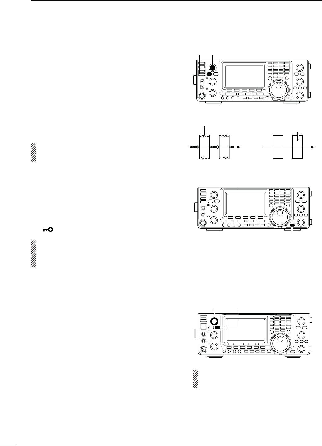
77
5FUNCTIONS FOR RECEIVE
N.OISE2EDUCTION
The Noise Reduction function reduces random noise
components and enhances audio signals which are
buried in noise. The received signals are converted
to digital signals and then the audio signals are sepa-
rated from the noise.
q Push [NR] to turn ON the Noise Reduction.
sh.2vAPPEARS
w Rotate the [NR] control to adjust the noise reduc-
tion level.
e Push [NR] to turn OFF the Noise Reduction.
sh.2vDISAPPEARS
A large rotation of the [NR] control results in audio
signal masking or distortion. Set the [NR] control for
maximum readability.
N.OTCHFUNCTION
-ODE !UTONOTCH 33"!-&-
-ANUALNOTCH33"#72449!-
This transceiver has Auto and Manual Notch functions.
The Auto Notch function uses DSP to automatically
attenuate beat tones, tuning signals, etc., even if their
frequencies are changing. The Manual Notch function
allows you to manually attenuate a frequency via the
[NOTCH] control.
±
In the SSB or AM mode, push [NOTCH] to toggle
the Notch function between auto, manual and OFF.
s%ITHERTHE!UTOOR-ANUALNOTCHFUNCTIONCANBETURNED
OFF in the Set mode. (p. 165)
±)NTHE#7OR2449MODEPUSH;./4#(=TOTURN
the Manual Notch function ON or OFF.
± In the FM mode, push [NOTCH] to turn the Auto
Notch function ON or OFF.
sh-.&vAPPEARSWHENTHE-ANUAL.OTCHFUNCTIONIS/.
sh!.&vAPPEARSWHENTHE!UTO.OTCHFUNCTIONIS/.
s.OINDICATORAPPEARSWHENTHENOTCHlLTERIS/&&
s7HEN THE -ANUAL.OTCHFUNCTIONIS /. HOLD DOWN
[NOTCH] for 1 second to select the wide, mid, or narrow
manual notch filter width.
N$IAL,OCKFUNCTION
The Dial Lock function prevents frequency changes by
accidental movement of [MAIN DIAL] by electronically
locking it.
± Hold down [SPEECH/LOCK] to turn the Dial Lock
function ON or OFF.
sh ” appears when the function is ON.
NOTE: When the “[SPEECH/LOCK] SW” item is set
to “LOCK/SPEECH” in the Set mode, pushing
[SPEECH/LOCK] turns ON the Dial Lock function.
(p. 164)
[NR] control[NR]
[SPEECH/LOCK]
[NOTCH] control [NOTCH]
While tuning the manual notch filter, noise may
be heard. This comes from the DSP unit and
does not indicate an equipment malfunction.
.OISEREDUCTION/..OISEREDUCTION/&&
Desired
signal (CW)
Noise components
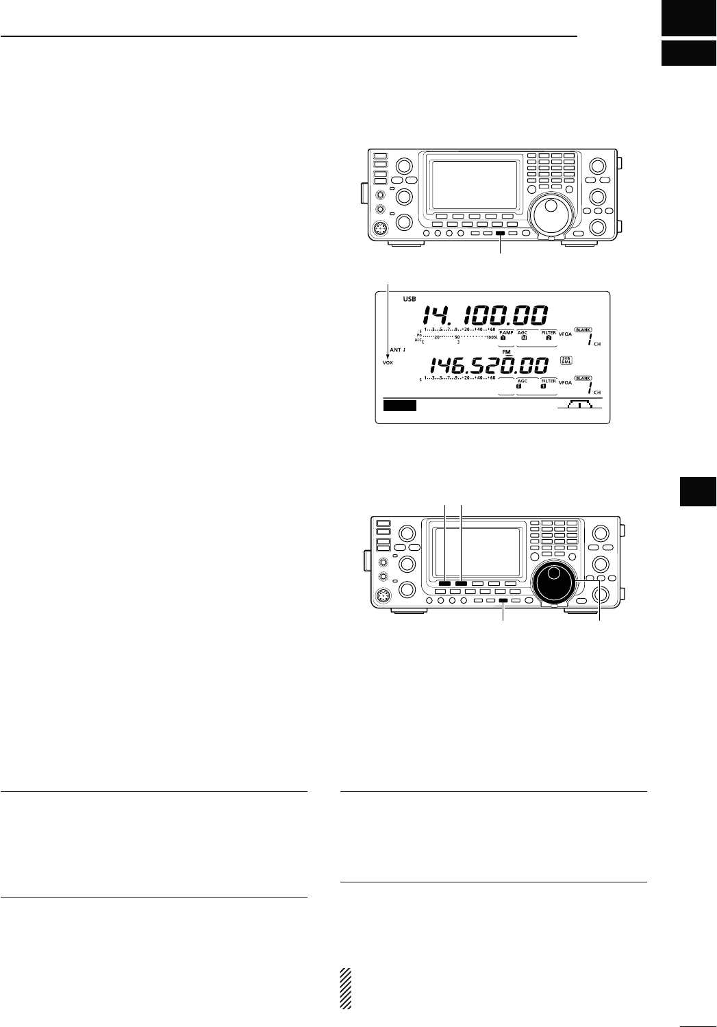
6
78
FUNCTIONS FOR TRANSMIT
6
N6/8FUNCTION
-ODE33"!-&-$6
The VOX (Voice-Operated Transmission) function
switches the transceiver between transmit and receive
with your voice. This function provides hands-free op-
eration.
D5SINGTHE6/8FUNCTION
q Select a phone mode (SSB, AM, FM, DV). (p. 43)
w Push [VOX/BK-IN] to turn ON the VOX function.
sh6/8vAPPEARS
The optional UT-121 is required for DV mode operation.
D!DJUSTINGTHE6/8FUNCTION
q Select a phone mode (SSB, AM, FM, DV). (p. 43)
w Hold down [VOX/BK-IN] for 1 second to display the
“VOX” screen.
e Push
[Y](F-1) or [Z](F-2)
to select the VOX Gain
item.
r While speaking into the microphone, rotate [MAIN
DIAL] to the point where the transceiver is continu-
ously transmitting.
t If the receive audio from the speaker causes the
VOX circuit to switch to transmit, push [Y] (F-1) or
[Z] (F-2) to select the Anti-VOX item. Then adjust
the anti-VOX setting to the point where receive
audio does not activate the VOX.
y Adjust the VOX delay for a convenient interval be-
fore returning to receive after you stop speaking.
u
Set the VOX voice delay, if desired.
i Push [MENU] to return to the previous menu.
6/8'AIN1. $EFAULT
!DJUSTTHE6/8GAINTOBETWEENANDIN
steps.
Higher values make the VOX function more sensitive
to your voice.
!NTI6/82. $EFAULT
!DJUSTTHE!.4)6/8GAINTOBETWEENAND
INSTEPS
Higher values make the VOX function less sensitive to
the received audio from a speaker or headphones.
6/8$ELAY3. $EFAULTS
Set the VOX delay to between 0.0 and 2.0 seconds,
for normal pauses in speech before returning to re-
ceive.
6/86OICE$ELAY4. $EFAULT/&&
Set the VOX voice delay to prevent clipping of the
first few syllables of a transmission when switching to
transmit.
OFF, Short, Mid and Long settings can be set.
When using the VOX voice delay, turn OFF the TX
monitor function to prevent transmitted audio from
being echoed.
[VOX/BK-IN]
DUPAGC COMP TBW SCP
M1
Appears
[VOX/BK-IN] [MAIN DIAL]
[][]
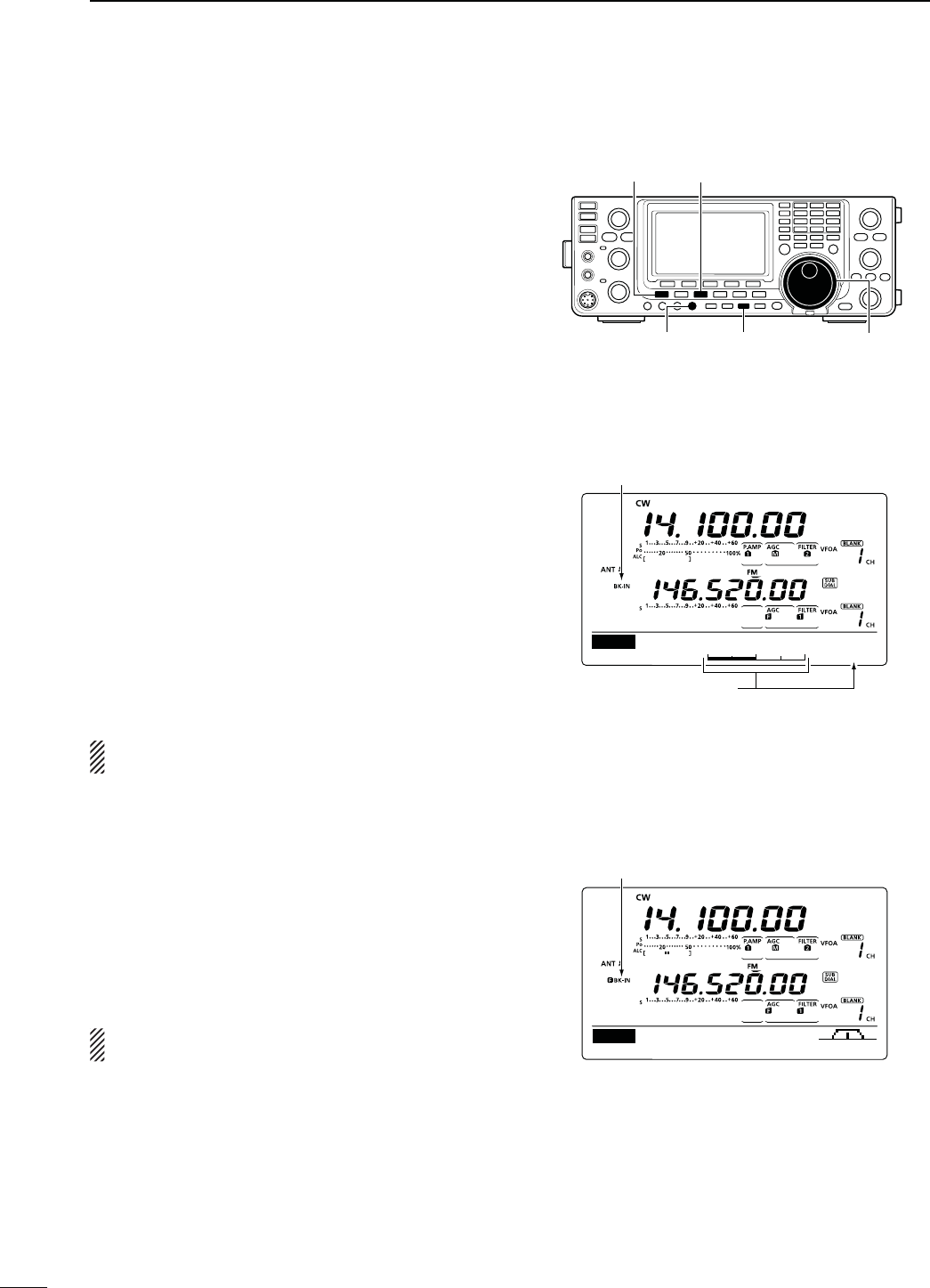
79
6FUNCTIONS FOR TRANSMIT
N"REAKINFUNCTION
(Mode: CW
The Break-in function is used in the CW mode to auto-
matically toggle the transceiver between transmit and
receive when keying. The IC-9100 is capable of Full
Break-in or Semi Break-in.
D3EMI"REAKINOPERATION
During Semi Break-in operation, the transceiver imme-
diately transmits when you key down, then returns to
receive after a pre-set delay time has passed after you
stop keying.
q0USH;#72449=TOSELECTTHE#7OR#72MODE
w Push [VOX/BK-IN] one or more times to turn ON
the Semi Break-in function.
sh"+).vAPPEARS
e Set the break-in delay time (the delay from transmit
to receive).
± Hold down [VOX/BK-IN] for 1 second to display
the “BKIN” screen (Break-in).
±
Rotate [MAIN DIAL] to select the desired delay.
s(OLDDOWN;&=FORSECONDTORESETTOTHEDEFAULT
setting, if desired.
r Push [MENU] to return to the previous menu.
7HENUSINGAPADDLEROTATE;+%930%%$=TOADJUST
the keying speed.
D&ULL"REAKINOPERATION
During Full Break-in operation, the transceiver trans-
mits when you key down, then immediately returns to
receive when you release.
q0USH;#72449=TOSELECTTHE#7OR#72MODE
w Push [VOX/BK-IN] one or more times to turn ON
the Full Break-in function.
shFBK-IN” appears.
7HENUSINGAPADDLEROTATE;+%930%%$=TOADJUST
the keying speed.
[MAIN DIAL][VOX/BK-IN][KEY SPEED]
[MENU] [CW/RTTY]
Appears
Shows break-in delay time
7.5d
BKIN
Break-IN Delay
DUPAGC 1⁄4 KEY SCP
M1
Appears
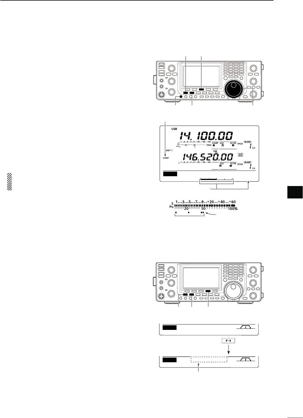
80
6
FUNCTIONS FOR TRANSMIT
6
N3PEECHCOMPRESSOR
-ODE33"
The Speech Compressor function increases average
RF output power, improving signal strength and read-
ability.
q Push [SSB] to select the USB or LSB mode.
w Adjust the [MIC GAIN] control so that the ALC
meter reads within the ALC zone, whether or not
you speak softly or loudly.
e
Push [MENU] to display the “M1” screen (Menu 1),
then push [COMP](F-3) to turn ON the Speech Com-
pressor.
r Hold down [COMP](F-3) for 1 second to display the
“COMP” screen (Compressor).
t While speaking into the microphone at your normal
voice level, rotate [MAIN DIAL] so the COMP meter
reads within the COMP zone.
s(OLDDOWN;&=FORSECONDTORESETTOTHEDEFAULTSET-
ting, if desired.
When the COMP meter peaks above the COMP
level zone, your transmitted voice may be dis-
torted.
y Push [MENU] to return to the previous menu.
N
4RANSMITlLTERWIDTHSELECTION
-ODE33"
The transmit filter width for the SSB mode can be se-
lected from Wide, Mid or Narrow.
q Push [SSB] to select the USB or LSB mode.
w
P
ush [MENU] to display the “M1” screen (Menu
1), then hold down [TBW](F-4) for 1 second, one
or more times, to select a Wide, Mid or Narrow
transmission passband width.
s0USH;4"7=&MOMENTARILYTODISPLAYTHESELECTED
TX filter width for approximately 1 second.
s4HEFOLLOWINGlLTERSARESPECIlEDASTHEDEFAULTS%ACH
of the filter widths can be set in the Tone control Set
mode. (pp. 169, 170)
- WIDE : 100 Hz to 2900 Hz
- MID : 300 Hz to 2700 Hz
- NAR : 500 Hz to 2500 Hz
Appears
Shows the compression level
5
COMP
COMP Level
COMP level zone
COMP meter
DUPAGC COMP TBW SCP
M1
DUPAGC COMP TBW SCP
M1
TBW WIDE
Hold down
The selected transmit filter width is
displayed for approximately 1 second.
[SSB]
[COMP]
[MAIN DIAL]
[MENU]
[MIC GAIN]
[SSB] [TBW][MENU]
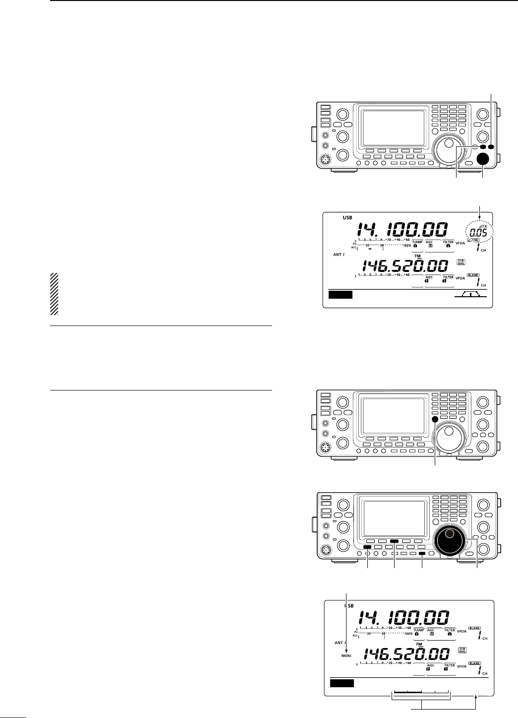
81
6FUNCTIONS FOR TRANSMIT
N ∂48FUNCTION
The ∂TX function shifts the transmit frequency up to
±9.99 kHz in 10 Hz steps* without changing the re-
ceive frequency.
* The [RIT/∂TX] control tunes in 1 Hz steps when the operating
frequency readout is set to the 1 Hz step readout. However,
the 1 Hz digit is not displayed on the frequency shift readout.
q Push [∂TX] to turn ON the ∂TX function.
sh∂TX” and the frequency shift appear when the function
is ON.
w Rotate [RIT/∂TX].
e To reset the ∂TX frequency, hold down [CLEAR] for
1 second.
s0USH;#,%!2=MOMENTARILYTORESETTHE∂TX frequency
when the Quick RIT Clear function is ON. (p. 164)
r To cancel the ∂TX function, push [∂TX] again.
sh∂TX” and the frequency shift disappear.
When the RIT and ∂TX functions are ON at the same
time, [RIT/∂TX] shifts both the transmit and receive
frequencies from the displayed frequency at the same
time.
&ORYOURCONVENIENCE#ALCULATEFUNCTION
The frequency shift of the ∂TX function can be added
to or subtracted from the displayed frequency.
± While displaying the ∂TX frequency shift, hold
down [∂TX] for 1 second.
D ∂48-ONITORFUNCTION
When the ∂TX function is ON, holding down [XFC] al-
lows you to
listen to the transmit frequency (including
the ∂TX frequency offset).
N-ONITORFUNCTION
The Monitor function allows you to monitor your trans-
mit IF signals in any mode. Use this to check voice
characteristics while adjusting SSB transmit param-
eters. (p. 169)
The CW sidetone functions regardless of the [MONI-
TOR] setting.
q Push [MONITOR] to turn ON the Monitor function.
sh-/.)vAPPEARSWHENTHE-ONITORFUNCTIONIS/.
w Hold down [MONITOR] for 1 second to display the
“MONI” screen (Monitor).
e Rotate [MAIN DIAL] to adjust the monitor level.
s&or the clearest audio output, adjust while holding
down [PTT] and speaking into the microphone.
s(OLDDOWN;&=FORSECONDTORESETTOTHEDEFAULTSET-
ting, if desired.
r Push [MENU] to return to the previous menu.
[∂TX] [RIT/∂TX]
[CLEAR]
DUPAGC COMP TBW SCP
M1
Appears
[XFC]
[MONITOR] [MAIN DIAL][MENU] [F-3]
Shows the monitor level
50%
MONI
MONITOR Level
Appears
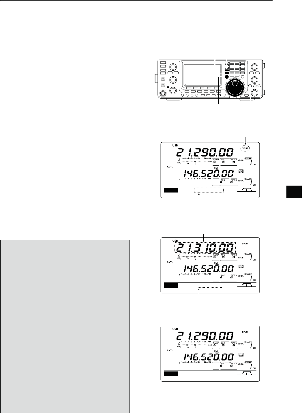
82
6
FUNCTIONS FOR TRANSMIT
6
N3PLITFREQUENCYOPERATION
Split frequency operation allows you to transmit and
receive on two different frequencies. Split frequency
operation is performed using frequencies in VFO A
and VFO B.
s4HE3PLITFREQUENCYOPERATIONISAUTOMATICALLYTURNED/&&
when turning ON the One-touch repeater function.
The following is an example of setting 21.290 MHz for
receiving and 21.310 MHz for transmitting.
q Set 21.290 MHz in VFO A.
w Push [SPLIT] to turn ON the Split operation.
s4HETRANSMIT6&/"FREQUENCYANDh30,)4vAPPEAR
e Hold down [A/B] for 1 second to equalize the trans-
mit (VFO B) frequency to the receive (VFO A) fre-
quency.
s4HEEQUALIZEDTRANSMIT6&/"FREQUENCYAPPEARS
s4HE1UICK3PLITFUNCTIONISMUCHMORECONVENIENTFOR
selecting the transmit frequency. See the next section
for details.
r While holding down [XFC], rotate [MAIN DIAL] to
set the transmit frequency to 21.310 MHz.
s4HETRANSMITFREQUENCYISDISPLAYEDWHILEHOLDINGDOWN
[XFC].
t Now you can receive on 21.290 MHz and transmit
on 21.310 MHz.
To change the transmit and receive frequencies, push
[A/B] to exchange VFO A and VFO B.
CONVENIENT
s$IRECTFREQUENCYSHIFTINPUT
The frequency shift can be entered directly.
q Push [F-INP ENT].
w Enter the desired frequency shift with the digit
keys.
sK(ZTO-(ZCANBESET
s7HENYOUREQUIREAMINUSSHIFTDIRECTIONlRSTPUSH
;'%.%s=
e Push [SPLIT] to input the frequency shift to the
transmit frequency, and the Split function is turned
ON.
[Example]
To transmit on a 1 kHz higher frequency:
- Push [F-INP ENT], [1] then [SPLIT].
To transmit on 3 kHz lower frequency:
0USH;&).0%.4=;'%.%s=;=THEN;30,)4=
s3PLIT,OCKFUNCTION
Accidentally releasing [XFC] while rotating [MAIN
DIAL] changes the receive frequency. To prevent this,
use both the Split Lock and Dial Lock functions to
change the transmit frequency only. The Split Lock
function cancels the Dial Lock function while holding
down [XFC] during split frequency operation.
The Split Lock function is OFF by default, but can be
turned ON in the Set mode. (p. 162)
[XFC] [MAIN DIAL]
[A/B] [SPLIT]
DUPAGC COMP TBW SCP
M1
14.10000
Appears
Shows transmit (VFO B) frequency
DUPAGC COMP TBW SCP
M1
+20.00k
Shows transmit (VFO B) frequency
Shows frequency shift and direction
s7HILEHOLDINGDOWN;8&#=
s!FTERSETTINGUP
DUPAGC COMP TBW SCP
M1
21.31000
s!FTERPUSHING;30,)4=
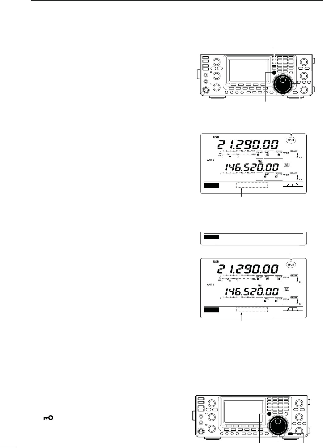
83
6FUNCTIONS FOR TRANSMIT
N1UICK3PLITFUNCTION
When you hold down [SPLIT] for 1 second, the Split
frequency operation is turned ON. The undisplayed
VFO is automatically changed according to the plus/
minus frequency shift programmed in the Set mode. Or
the VFOs are equalized when 0 kHz (default setting) is
programmed as the split frequency shift. (p. 162)
The Quick Split function is ON by default. For your
convenience, it can be turned OFF in the Set mode.
(p. 162) In this case, holding down [SPLIT] does not
equalize the VFO A and VFO B frequencies.
q Suppose you are operating at 21.290 MHz (USB) in
VFO A.
w Hold down [SPLIT] for 1 second.
s3PLITFREQUENCYOPERATIONISTURNED/.
s4HETRANSMIT6&/"FREQUENCYISEQUALIZEDTOTHERE-
ceive (VFO A) frequency.
e While holding down [XFC], rotate [MAIN DIAL] to
set the frequency offset between transmit and re-
ceive.
s7HEN;8&#=ISRELEASEDTHERECEIVEFREQUENCYISDIS-
played.
D3PLITFREQUENCYOFFSETSETTING
By setting an often-used split frequency offset in ad-
vance, you can use the Quick Split function to select
split operation at the push of one switch.
Set the split frequency offset in advance in the
“SPLIT
Offset” item of the
Set mode. (p. 162)
The example at right shows the split offset is set to
+0.020 MHz.
± Hold down [SPLIT] for 1 second. to activate the
Quick Split function.
s4HETRANSMITFREQUENCYSHIFTSFROMTHERECEIVEFREQUENCY
according to
the “SPLIT Offset” option in the Set mode
.
(p. 162)
D3PLIT,OCKFUNCTION
The Split Lock function is convenient for changing only
the transmit frequency. When the Split Lock function is
not used, accidentally releasing [XFC] while rotating
[MAIN DIAL], changes the receive frequency.
The Split Lock function is OFF by default, but can be
turned ON in the Set mode.
q While split frequency operation is ON, hold down
[SPEECH/LOCK] for 1 second to activate the split
lock function.
sh ” appears.
w While holding down [XFC], rotate [MAIN DIAL] to
change the transmit frequency.
s)F YOU ACCIDENTALLY RELEASE ;8&#= WHILE ROTATING THE
[MAIN DIAL], the receive frequency does NOT change.
DUPAGC COMP TBW SCP
M1
21.29000
Appears
Shows the equalized transmit (VFO B) frequency
s!FTERHOLDINGDOWN;30,)4=
DUPAGC COMP TBW SCP
M1
21.31000
Ù
16
Ú+0.020MHz
SET SPLIT Offset
Appears
Shows the shifted transmit (VFO B) frequency
s!FTERHOLDINGDOWN;30,)4=WHENTHESPLIT
OFFSETISSETTOhvINTHE3ETMODE
[XFC] [MAIN DIAL] [SPEECH/LOCK]
[XFC] [MAIN DIAL]
[SPLIT]
(Set mode screen)
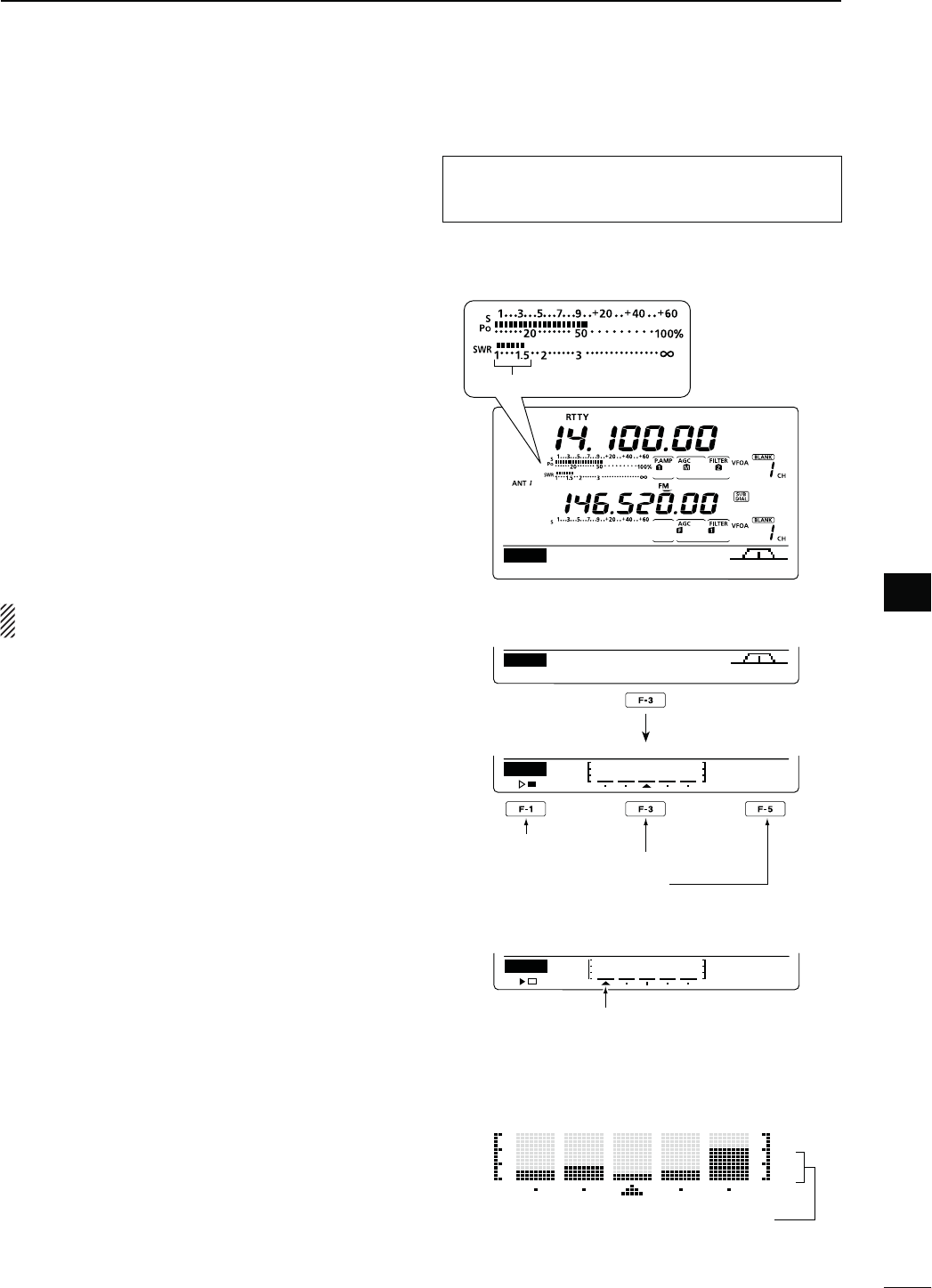
84
6
FUNCTIONS FOR TRANSMIT
6
N-EASURING372
"AND(&-(Z
The IC-9100 has a built-in circuit for measuring an-
tenna SWR— no external equipment or special adjust-
ments are necessary.
The IC-9100 can measure SWR two ways— spot mea-
surement and plot measurement.
D3POTMEASUREMENT
q Push [TUNER] once or twice to turn OFF the an-
tenna tuner.
w(OLD DOWN ;!.4s-%4%2= FOR SECOND ONE OR
more times, to select the SWR meter.
e0USH;#72449=ONCEORTWICETOSELECTTHE2449
mode.
r Push [PTT] on the microphone to transmit. (or
[TRANSMIT] on the transceiver).
t Rotate [RF POWER] clockwise past the 12 o’clock
POSITIONFORMORETHAN7OFOUTPUTPOWER
y Read the SWR on the SWR meter.
u Release [PTT] to receive. (or push [TRANSMIT]
again)
The built-in antenna tuner matches the transmitter
to the antenna when the SWR is less than 3:1.
D0LOTMEASUREMENT
Plot measurement allows you to measure the SWR
over an entire band.
q
P
ush [MENU] to display the “M2” screen (Menu 2),
then push [SWR](F-3).
s4HE372GRAPHSCREENAPPEARS
w Rotate [RF POWER] clockwise past the 12 o’clock
POSITIONFORMORETHAN7OFOUTPUTPOWER
e Set the center frequency for the SWR to be mea-
sured.
r Hold down [F-5] for 1 second one or more times to
select 10, 50, 100 or 500 kHz steps as the SWR
measuring step.
t Push [F-3] one or more times to select 3, 5, 7, 9, 11
or 13 steps as the number of measuring steps.
y Push [F-1] to start the measuring.
u Push [TRANSMIT] or hold down [PTT] on the mi-
crophone to measure the SWR.
s! FREQUENCY MARKER h∫,” appears below the SWR
graph.
i Push [TRANSMIT] again or release [PTT] to move
the frequency marker and frequency indication to
the next frequency to be measured.
o Repeat steps u and i to measure SWR over the
entire frequency range.
!0 When the measured SWR is more than 1.5:1, ad-
just the antenna to match with the transceiver.
DUPAGC 1⁄4 RTTY SCP
M1
The best match is in this range.
MEM
SCAN
SWR
TCON
VSC
M2
SWR
10k
STEP
Push
Start measuring
Select number of SWR measuring steps
Select SWR measuring step
s-EASURING (after pushing [F-1])
SWR
10k
STEP
Frequency marker appears and moves
after measurement.
When mesurement points are set out-
side of the operatable frequency band,
the frequency marker blinks.
Typical display SWR varying between 1 and 2,
full scale up to SWR 4.0:1.
101
151
201
301
The antenna SWR cannot be measured on the 1200
MHz frequency band*.
* The optional UX-9100 is required.
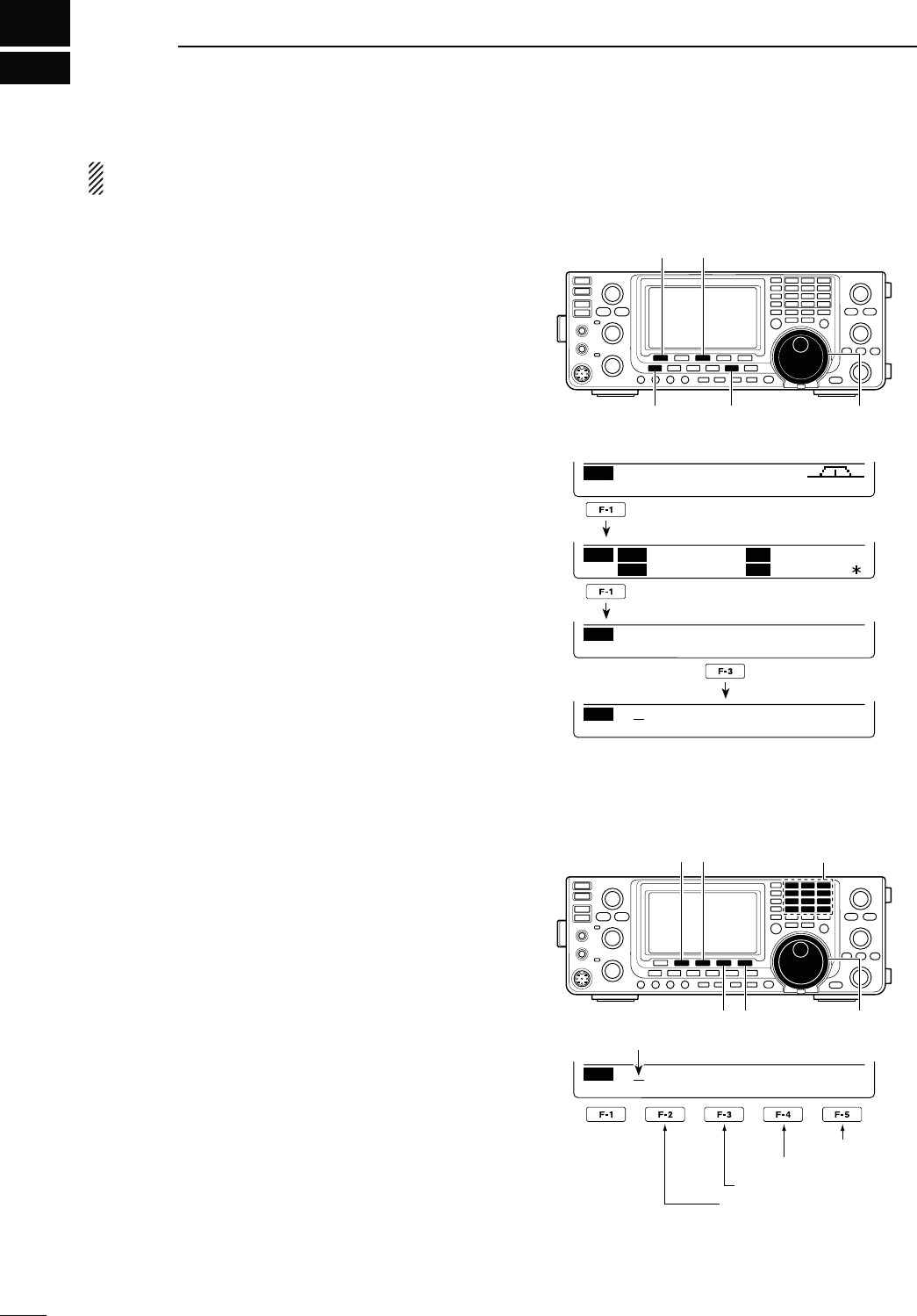
7
85
DV MODE PROGRAMMING
The optional UT-121 is required for DV mode opera-
tion.
N #ALLSIGNPROGRAMMING
&OURTYPESOFCALLSIGNSAREUSEDh-9vYOUROWNCALL
sign) “UR” (destination call sign, whether it is an indi-
vidual or a repeater.) “R1” (your access/area repeater
call sign) and “R2” (a destination or gateway repeater
call sign). Each call sign can be programmed with up
to 8 characters.
)NADDITIONYOUCANSTOREUPTOh-9vCALLSIGNSAND
up to 60 “UR” call signs in the call sign memory. Up to
300 repeater call signs can be stored in the repeater
list.
D h-9v9OUROWNCALLSIGNPROGRAMMING
9OUROWNCALLSIGNMUSTBEPROGRAMMEDFORBOTHDIGI-
tal voice and low-speed data communications (includ-
ing GPS transmission).
q Push [DVsDR] to select the DV mode.
w
P
ush [MENU] one or more times to display the “M3”
screen (Menu 3).
s)NTHE$2MODEP
ush [MENU] once or twice to select
the “D1” screen.
e
P
ush [CS](F-1) to display the “CS” screen (Call
Sign).
r
P
ush [Z](F-1) one or more times to display the h-9v
screen (-9CALLSIGNSETTING).
t2OTATE;-!).$)!,=TOSELECT-9OR
call sign memory.
y Push [EDT](F-3) to enter the call sign programming
mode.
s!CURSORAPPEARSANDBLINKS
u Rotate [MAIN DIAL] to select the first character to
input.
When inputting numbers, push the appropriate key-
pad key.
s0USH;$%,=&TODELETE THESELECTEDCHARACTEROR
number.
s0USH;30#=&TOINPUTASPACE
i Push [Ω](F-2) to move the cursor backwards, or
push [≈](F-3) to move the cursor forwards.
o Repeat steps u and i to enter your own call sign.
s!CALLSIGNOFUPTODIGITSCANBESET
s4OPROGRAMANOTEUPTOCHARACTERSFOROPERATING
radio type, area, etc.), go to step !0, otherwise go to
step !2.
!0 Push [≈](F-3) to move the cursor right side of “/”.
!1 Repeat steps u and i to program the desired 4
character note.
!2 Push [MENU] to store the programmed call sign
and note.
!3 Push [MENU] again to return to the “CS” screen.
[CS]/[√] [EDT]
[MENU] [DV・DR] [MAIN DIAL]
CS CD R>CS UR DSET
M3
CS U
R
CQCQCQ
M
Y
R
1
R
2
NOT USE
Ú
MY
/ MY1
CLR EDT NAME
MY
/ MY1
DEL SPC
MY
/ MY1
DEL SPC
Cursor
[][]
[DEL][SPC] [MAIN DIAL]
s0ROGRAMINGACALLSIGN
Input a space
Delete a character
Move cursor forwards
Move cursor backwards
Number input
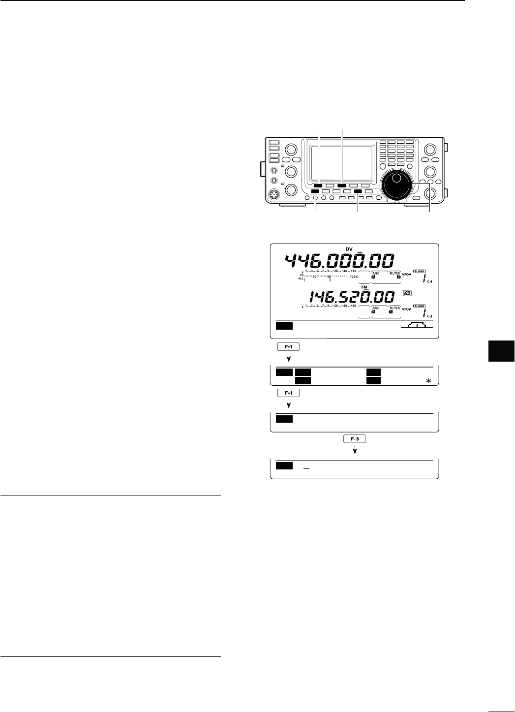
86
7
DV MODE PROGRAMMING
7
D h52v$ESTINATIONCALLSIGNPROGRAMMING
A destination call sign must be programmed to a spe-
cific individual station or a repeater, for both digital
voice and low-speed data communications.
q Push [DVsDR] to select the DV mode.
w
P
ush [MENU] one or more times to display the “M3”
screen (Menu 3).
s)NTHE$2MODEP
ush [MENU] once or twice to select
the “D1” screen.
e
P
ush [CS](F-1) to display the “CS” screen (Call
Sign).
r
P
ush [Z](F-1) one or more times to display the “UR”
screen (UR call sign setting).
t Rotate [MAIN DIAL] to select the desired call sign
memory between “U01” and “U99.”
y Push [EDT](F-3) to enter the call sign programming
mode.
s!CURSORAPPEARSANDBLINKS
u Rotate [MAIN DIAL] to select the first character to
input.
When inputting numbers, push the appropriate key-
pad key.
s0USH;$%,=&TODELETE THESELECTEDCHARACTEROR
number.
s0USH;30#=&TOINPUTASPACE
i Push [Ω](F-2) to move the cursor backwards, or
push [≈](F-3) to move the cursor forwards.
o Repeat step u to enter UR call sign.
s!CALLSIGNOFUPTODIGITSCANBESET
!0 Push [MENU] to store the programmed call sign.
!1 Push [MENU] again to return to the “CS” screen.
For your information
The IC-9100 has a call sign edit record function.
When you edit a call sign that is stored in a call sign
memory, the edited call sign is automatically pro-
grammed into a blank channel.
If all call sign memories are already programmed, the
edited call sign will overwrite the selected channel’s
call sign.
The programmed call sign can be over-written anytime,
when the “Edit Record” item is set to OFF or Select, in
the DV Set mode. (p. 119)
However, the call sign that is stored in a regular mem-
ory or call channel must be manually overwritten.
(Temporary operation is possible).
[CS]/[√] [EDT]
[MENU] [DV・DR] [MAIN DIAL]
CS CD R>CS UR DSET
M3
CS U
R
CQCQCQ
M
Y
R
1
R
2
NOT USE
Ú
UR
CQCQCQ
UR
CLR EDT NAME GRP
UR
U01
DEL SPC
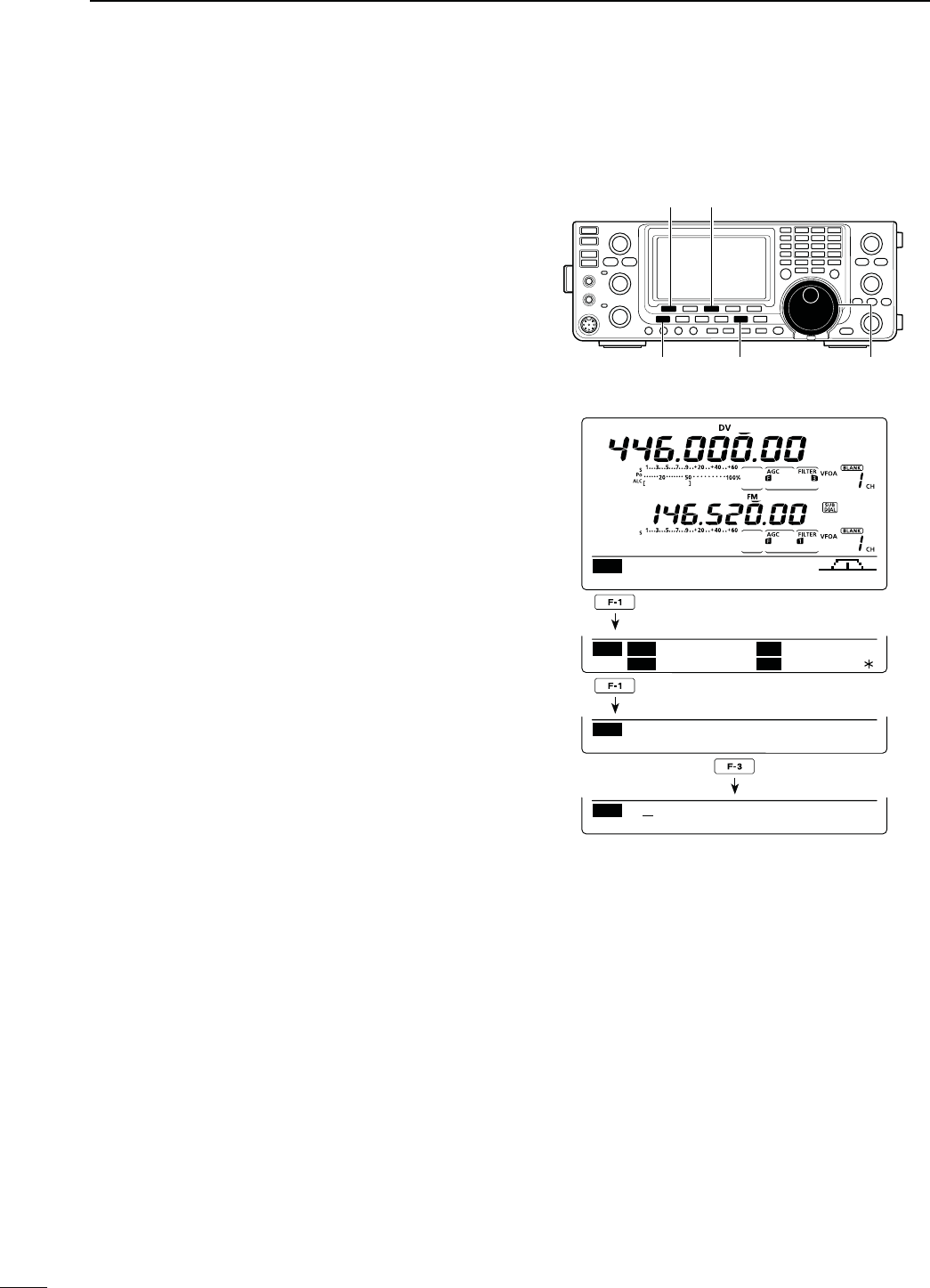
87
7DV MODE PROGRAMMING
The access/area and link/gateway repeater call signs
must be programmed in “R1” and “R2.”
Other repeater call signs can be stored in the “RP-L”
screen (Repeater list)
(p. 88)
.
q Push [DVsDR] to select the DV mode.
w
P
ush [MENU] one or more times to display the “M3”
screen (Menu 3).
s)NTHE$2MODEP
ush [MENU] once or twice to select
the “D1” screen.
e
P
ush [CS](F-1) to display the “CS” screen (Call
Sign).
r
P
ush [Z](F-1) one or more times to display the “R1”
or “R2” screen (Repeater call sign setting).
t Push [EDT](F-3) to enter the call sign programming
mode.
s!CURSORAPPEARSANDBLINKS
y Rotate [MAIN DIAL] to select the first character to
input.
When inputting numbers, push the appropriate key-
pad key.
s0USH;$%,=&TODELETE THESELECTEDCHARACTEROR
number.
s0USH;30#=&TOINPUTASPACE
u Push [Ω](F-2) to move the cursor backwards, or
push [≈](F-3) to move the cursor forwards.
i Repeat steps y and u to enter a desired repeater
call sign.
s!CALLSIGNOFUPTODIGITSCANBESET
o Push [MENU] to store the programmed call sign.
!0 Push [MENU] again to return to the “CS” screen.
[CS]/[√] [EDT]
[MENU] [DV・DR] [MAIN DIAL]
CS CD R>CS UR DSET
M3
CS U
R
CQCQCQ
M
Y
R
1
R
2
NOT USE
Ú
R1
R1
CLR EDT NAME GRP
R1
R1
DEL SPC
N Call sign programming (Continued)
D h2v!CCESS!REAREPEATERCALLSIGNANDh2v,INK'ATEWAYREPEATERCALLSIGNPROGRAMMING
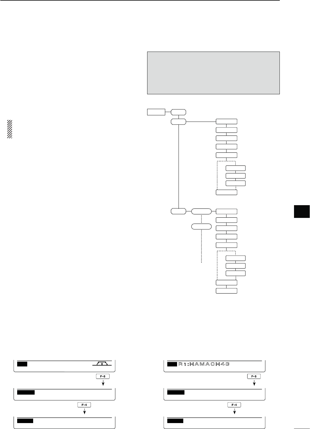
88
7
DV MODE PROGRAMMING
7
N2EPEATERLIST
9OUCANSTOREREPEATERINFORMATIONFORQUICKANDSIMPLE
communication in up to 500 repeater memory chan-
nels (Repeater list) in up to 10 Groups. Programming
the repeater list is required for DR mode operation.
The outline of the repeater list is as follows:
q Adding new repeaters or editing a list
w Selecting a repeater to edit
e
Programming repeater data (Repeater name, Call sign,
Gateway repeater call sign, Repeater group, etc.)
If a call sign has been programmed, you can skip
other data programming, and write only the call
sign into the Repeater list.
r Programming access repeater data (Receive fre-
quency, Duplex direction, Frequency offset)
D2EPEATERLISTCONTENTS
The following contents are included in the repeater list:
CLR (Repeater list clearing) (p. 92)
ADD (Repeater list addition) (p. 89)
EDT (Repeater list editing) (p. 91)
NAME (Repeater name) (p. 89)
CS (Repeater call sign) (p. 89)
GW (Gateway repeater’s call sign) (p. 90)
GROUP (Repeater group) (p. 90)
R1 USE (Access repeater use) (p. 90)
FREQ (Repeater input frequency)* (p. 90)
DUP (Duplex direction)* (p. 91)
OFFSET (Frequency offset)* (p. 91)
ADD Write (Save and add to the repeater list)
(pp. 91, 92)
OVER Write (Save and overwrite to the repeater
list) (p. 92)
!PPEARSWHEN253%ISSELECTEDAS9%3
NOTE: Repeater lists can be erased by static elec-
tricity, electric transients, etc. In addition, they can
be erased by an equipment malfunction, and during
repairs. Therefore, we recommend that memory data
be backed up externally, or be saved to a PC using
the optional CS-9100 CLONING SOFTWARE.
RPT-L
ADD
EDT
YESNO
FREQ
DUP
OFFSET
YESNO
FREQ
DUP
OFFSET
CLR
NAME
R1USE
CS
GW
GROUP
ADD Write
Repeater 1
Repeater 5
NAME
R1USE
CS
GW
GROUP
ADD Write
OVER Write
q
w
e
r
s4OSELECTTHE2EPEATERLISTENTRYMODE
q In
the DV mode, p
ush [MENU] one or more times to
select
the “M3” screen (Menu 3)
.
s)NTHE$2MODEP
ush [MENU] once or twice to select
the “D1” screen.
w Push [DSET](F-5) to display the “DSET” screen.
e Push [RP-L](F-4) to display the “RP-L” screen (Re-
peater list).
RP–L
Repeater List
CLR ADD EDT
RP–L
Repeater List
CLR ADD EDT
DSET
TXM RP
—
L SET
DSET
TXM RP
—
L SET
CS CD R>CS UR DSET
M3
CS CD R>CS UR DSET
D1
GRP1
A CH4
)NTHE$6MODE )NTHE$2MODE
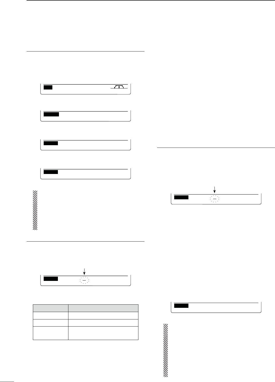
89
7DV MODE PROGRAMMING
N
2EPEATERLISTPROGRAMMING
.EWREPEATERLIST1. PROGRAMMING
q Push [DVsDR] to select the DV mode.
w
P
ush [MENU] one or more times to display the “M3”
screen (Menu 3).
s)NTHE$2MODEP
ush [MENU] once or twice to select
the “D1” screen.
CS CD R>CS UR DSET
M3
When the “M3” screen is selected.
e Push [DSET](F-5) to display the “DSET” screen.
DSET
TXM RP
—
L SET
r Push [RP-L](F-4) to display the “RP-L” screen (Re-
peater list).
RP–L
Repeater List
CLR ADD EDT
t
P
ush [ADD](F-3) to display the “NAME” item (Re-
peater name).
RP–L
NAME:
ÚEDTÙ
4OCANCELTHEPROGRAMMEDDATA
After programming, push [MENU] to display
h#ANCEL/+v0USH;9%3=&TOCANCELPRO-
gramming and return to the “RP-L” screen (Re-
peater list), or push [NO](F-5) to keep program-
ming and return to the previous screen which
was selected before pushing [MENU].
2EPEATERNAMEPROGRAMMING2.
y Push [EDT](F-4) to enter the repeater name pro-
gramming mode.
s!CURSORAPPEARSANDBLINKS
Blinks
RP–L
NAME:
ABC
DEL SPC
u Push [ABC](F-1) one or more times to select the
desired character type.
#HARACTERTYPE 3ELECTABLECHARACTERS
ABC A to Z
abc a to z
etc <" ’ ` ^ + – 1b
< > ( ) [ ] { } ¦ _ ¯ @
i Rotate [MAIN DIAL] to select the first character or
symbol to input.
When inputting numbers or a decimal point, push
the appropriate keypad key.
s0USH;$%,=&TODELETETHESELECTEDCHARACTERSYM-
bol or number.
s0USH;30#=&TOINPUTASPACE
s7HENALLCHARACTERSHAVEBEENprogrammed, an error
beep sounds. If you want to reprogram, push [Ω](F-2) or
[≈](F-3) to select a character, then push [DEL](F-4) to
delete it.
o Push [Ω](F-2) to move the cursor backward, or push
[≈](F-3) to move the cursor forward.
!0 Repeat steps u through i to program a name of
up to 9 characters.
!1 Push [MENU] to save the name.
2EPEATER3. CALLSIGNPROGRAMMING
!2 Push [Z](F-2) to display the “CS” item (Repeater
Call Sign).
!3 Push [EDT](F-4) to enter the repeater call sign pro-
gramming mode.
s!CURSORAPPEARSANDBLINKS
RP–L
CS :
DEL SPC
Blinks
!4 Rotate [MAIN DIAL] to select the first character or
symbol (‘/’only) to input.
When inputting numbers, push the appropriate key-
pad key.
s0USH;$%,=&TODELETETHESELECTEDCHARACTERSYM-
bol or number.
s0USH;30#=&TOINPUTASPACE
s7HENALLCHARACTERSHAVEBEENprogrammed, an error
beep sounds. If you want to reprogram, push [Ω](F-2) or
[≈](F-3) to select a character, then push [DEL](F-4) to
delete it.
!5 Push [Ω](F-2) to move the cursor backward, or push
[≈](F-3) to move the cursor forward.
!6 Repeat steps !4 through !5 to program a repeater
call sign of up to 8 characters.
!7 Push [MENU] to save the call sign.
RP–L
CS :
JP3YHH B
ÚEDTÙ
Be sure to add a letter after a repeater call sign,
as the repeater node (port), according to the re-
peater frequency, as shown below. Note that
Japanese repeater node letters are different.
s-(Z!"IN*APAN
s-(Z "!IN*APAN
s-(Z #NO$34!2REPEATERSIN*APAN
Cross band operation between different nodes in
the same repeater area can be made.
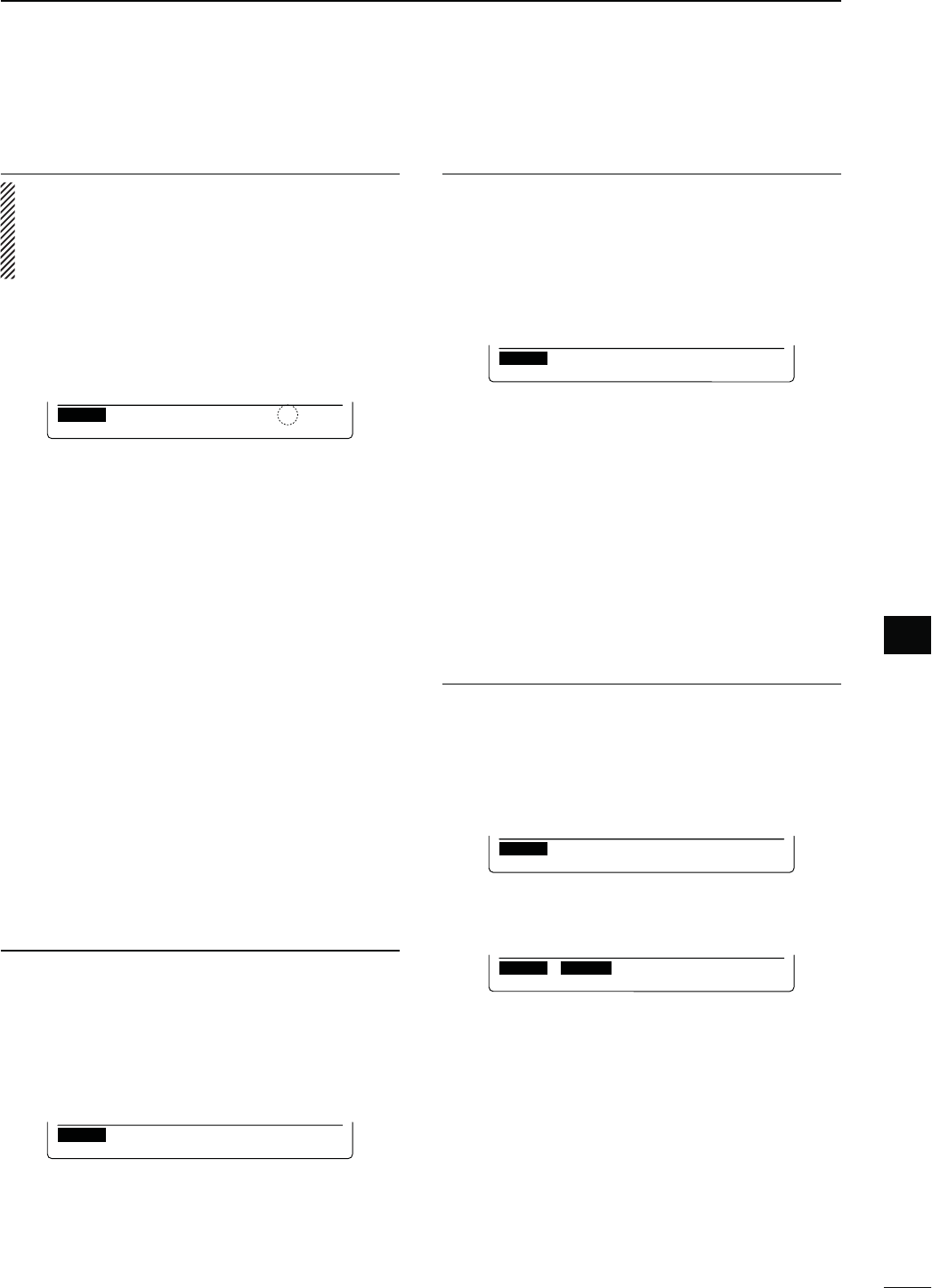
90
7
DV MODE PROGRAMMING
7
'ATEWAYR4. EPEATERCALLSIGNPROGRAMMING
When the repeater that was programmed in the pre-
vious item has its own gateway capability, skip this
setting and go to the next item. If the programmed
repeater uses a different gateway repeater, program
gateway repeater’s call sign as described below.
!8 Push [Z](F-2) to display the “GW” item (Gateway
Repeater Call Sign).
s4HEPROGRAMMEDREPEATER’s call sign is displayed, and
“G” is automatically added as, or overwrites, the 8th
digit.
RP–L
GW :
JP3YHH G
ÚEDTÙ
!9 Push [EDT](F-4) to enter the repeater call sign pro-
gramming mode.
s!CURSORAPPEARSANDBLINKS
@0 Push [Ω](F-2) or [≈](F-3) to select the character to
program.
@1 Rotate [MAIN DIAL] to select the first character or
symbol (‘/’ only) to input.
When inputting numbers, push the appropriate key-
pad key.
s0USH;$%,=&TODELETETHESELECTEDCHARACTERSYM-
bol or number.
s0USH;30#=&TOINPUTASPACE
s7HENALLCHARACTERSHAVEBEENprogrammed, an error
beep sounds. If you want to reprogram, push [Ω](F-2) or
[≈](F-3) to select a character, then push [DEL](F-4) to
delete it.
@2 Repeat steps @0 through @1 to program a repeater
call sign of up to 8 characters.
s4HETHDIGITMUSTBEh'v
s&ORREPEATERSINAZONEWITHNOGATEWAYENTERACOM-
mon name or call sign, up to 7 digits, in all their gateway
repeater cells. The 8th digit must be blank.
@3 Push [MENU] to save the programmed call sign.
R5. EPEATERGROUPPROGRAMMING
4HE)#HASATOTALOFGROUPSn9OUCAN
assign and organize up to 500 repeaters in the 10
groups. Group selection is helpful for quick recall of a
desired repeater.
@4 Push [Z](F-2) to display the “GROUP” item (Re-
peater group).
s3ELECTEDGROUPNUMBERAPPEARS
RP–L
GROUP:
GRP1
@5
Rotate [MAIN DIAL] to
select the desired repeater
group.
!CCESSREPEATERSETTING253%6.
The programmed repeaters can be set as an access
repeater (R1) in the DR mode. To use as R1, the re-
peater frequency, duplex direction and frequency off-
set must be programmed.
@6 Push [Z](F-2) to display the “R1USE” item (Access
Repeater Programming).
s4HEACCESSREPEATERPROGRAMMINGSCREENAPPEARS
RP–L
R1USE:
YES
@7
Rotate [MAIN DIAL] to
select
h9%3vORh./v
s7HENh./vISSELECTEDTHEREPEATERCANNOTBESELECTED
as an access repeater (R1) in the DR mode.
s7HENh9%3vISSELECTEDTHEREPEATERCANBESELECTED
as an access repeater (R1) in the DR mode.
± When “NO” is selected in step @7, skip ‘Frequency
programming (FREQ)’ and go to ‘Duplex direction
setting (DUP).’
± 7HENh9%3vISSELECTEDINSTEP@7, push [Z](F-2) to
go to step @8 for the access repeater (R1) program-
ming.
&REQUENCYPROGRAMMING&2%17.
This content appears when “9%3” is selected in “R1
USE,” as described in ‘Access repeater setting (R1
USE)’ above.
@8 Push [Z](F-2) to display the “FREQ” item (Fre-
quency Programming).
s4HEFREQUENCYPROGRAMMINGSCREENISDISPLAYED
RP–L
FREQ:
..
ÚCLR EDTÙ
@9 Push [EDT](F-4) to enter the frequency program-
ming mode.
s!CURSORAPPEARSANDBLINKS
RP–L
:
..
ÚÙ
F-INP
#0
Push the
keypad key
to
input the frequency, then
push [F-INP ENT].
s(OLDDOWN;#,2=&FORSECONDTOCLEARTHEDIS-
played frequency.
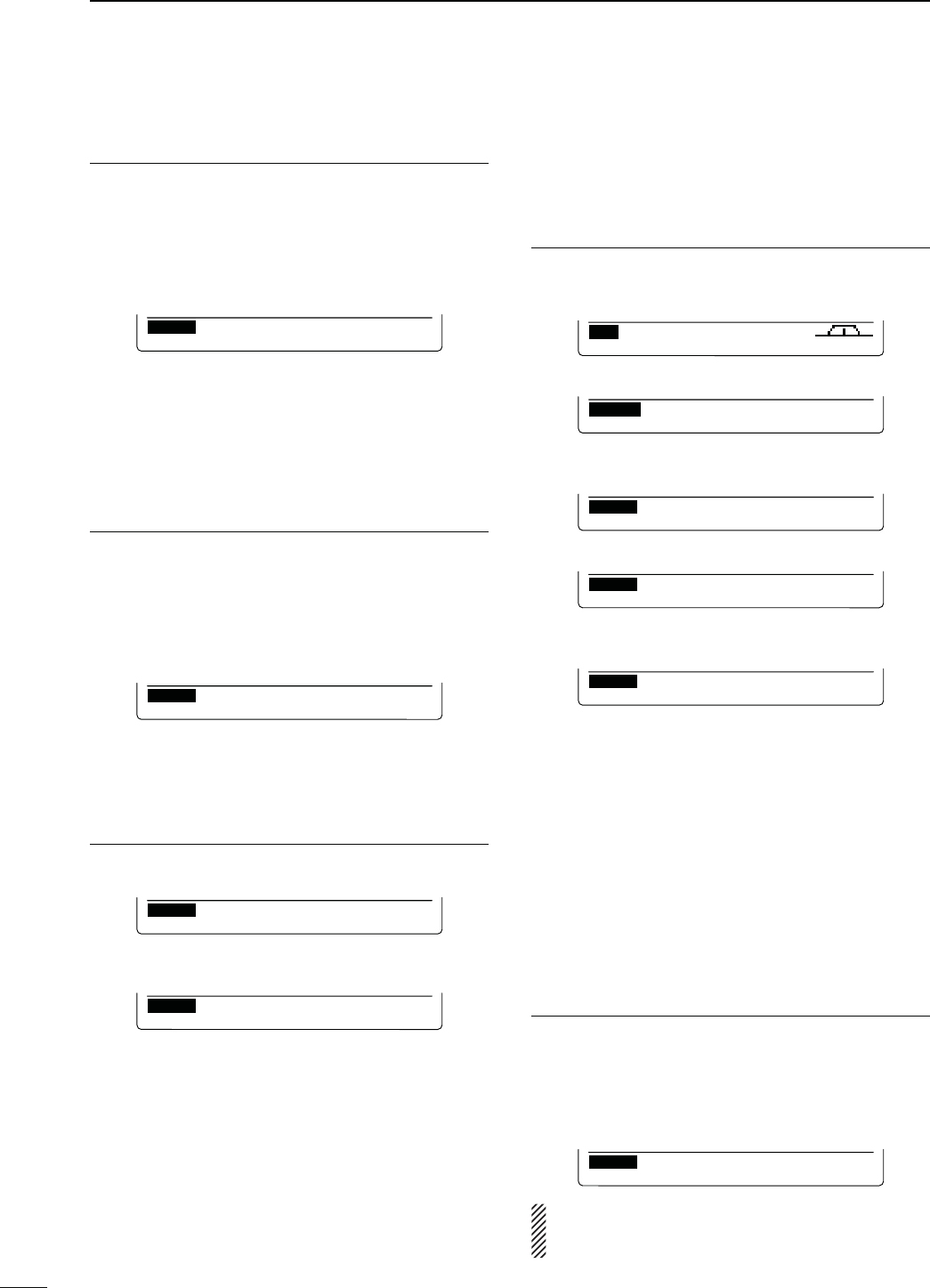
91
7DV MODE PROGRAMMING
$UPLEXDIRECTIONSETTING$508.
This content appears when “9%3” is selected in “R1
USE” as described in ‘Access repeater setting (R1
USE)’ on page 90.
#1 Push [Z](F-2) to display the “DUP” item (Duplex di-
rection setting).
s4HEDUPLEXDIRECTIONSETTINGSCREENISDISPLAYED
RP–L
DUP :
OFF
#2 Rotate [MAIN DIAL] to select the duplex direction.
s OFF : The duplex function is OFF.
s DUP– : The transmit frequency shifts down from the re-
ceive frequency by the offset amount.
s DUP+ : The transmit frequency shifts up from the re-
ceive frequency by the offset amount.
&REQUENCYOFFSETPROGRAMMING/&&3%49.
This content appears when “9%3” is selected in “R1
USE” as described in ‘Access repeater setting (R1
USE)’ on page 90.
#3 Push [Z](F-2) to display the “OFFSET” item (Fre-
quency offset Programming).
s&REQUENCYOFFSETPROGRAMMINGSCREENISDISPLAYED
RP–L
OFFSET:
0.000.0
CLR
#4 Rotate [MAIN DIAL] to select the frequency offset.
s(OLDDOWN;#,2=&FORSECONDTOCLEARTHEDIS-
played frequency offset.
3TORINGTHEREPEATERLIST!$$710. RITE
#5 Push [Z](F-2) to display the “ADD Write” item (Re-
peater list Storing).
RP–L
ADD Write
ÚWRÙ
#6 Hold down [WR](F-5) to store the entry.
sh!$$7RITE/+vAPPEARS
RP–L
ADD Write OK?
ÚYES NOÙ
#7 Hold down ;9%3=&TOSTORETHEENTRYANDRETURN
to the RP-L screen.
N%DITINGAREPEATERLIST
This function re-programs a repeater’s data. This is
useful when already-programmed data is incorrect or
some data should be added to the list.
2EPEATERLISTSELECTION1.
q Push [DVsDR] to select the DV mode.
w
P
ush [MENU] one or more times to display the “M3”
screen (Menu 3).
CS CD R>CS UR DSET
M3
e Push [DSET](F-5) to display the “DSET” screen.
DSET
TXM RP
—
L SET
r Push [RP-L](F-4) to display the “RP-L” screen (Re-
peater list).
RP–L
Repeater List
CLR ADD EDT
t
P
ush [EDT](F-5) to display the repeater list.
RP–L
HAMACH43 GRP1
SEL
SEL GRPEDT
y Rotate [MAIN DIAL] to select the desired repeater
to be changed.
RP–L
KOUTOU43 GRP1
SEL
SEL GRPEDT
sHold down [GRP](F-5) for 1 second to enter the
repeater group selection mode. (“≈” moves next
to the repeater group name, and then blinks.)
Rotate [MAIN DIAL] to select the desired group (0
to 9), then push [GRP](F-5).
Or, you can select the repeater group using the
keypad key.
s“SEL” appears when “R1 USE” setting is set to
“9%3” The selected repeaters can be used as an
access repeater (R1) in the DR mode, and are
scanned during an access repeater scan.
9OUCANSETTHEh3%,vSETTINGBYPUSHING[SEL](F-4).
2EPEATERDATAPROGRAMMING2.
u Push [EDT](F-1) to enter the repeater data pro-
gramming mode.
i Push [Y](F-1) or [Z](F-2) to select the item to be
changed.
o Program the selected item data. See pages 89–91
for new repeater list programming details.
RP–L
NAME:
KOUTOU43
ÚEDTÙ
NOTE: If you are reprogramming a repeater with its
own gateway, you must also edit the gateway re-
peater call sign.
N
Repeater list programming (Continued)
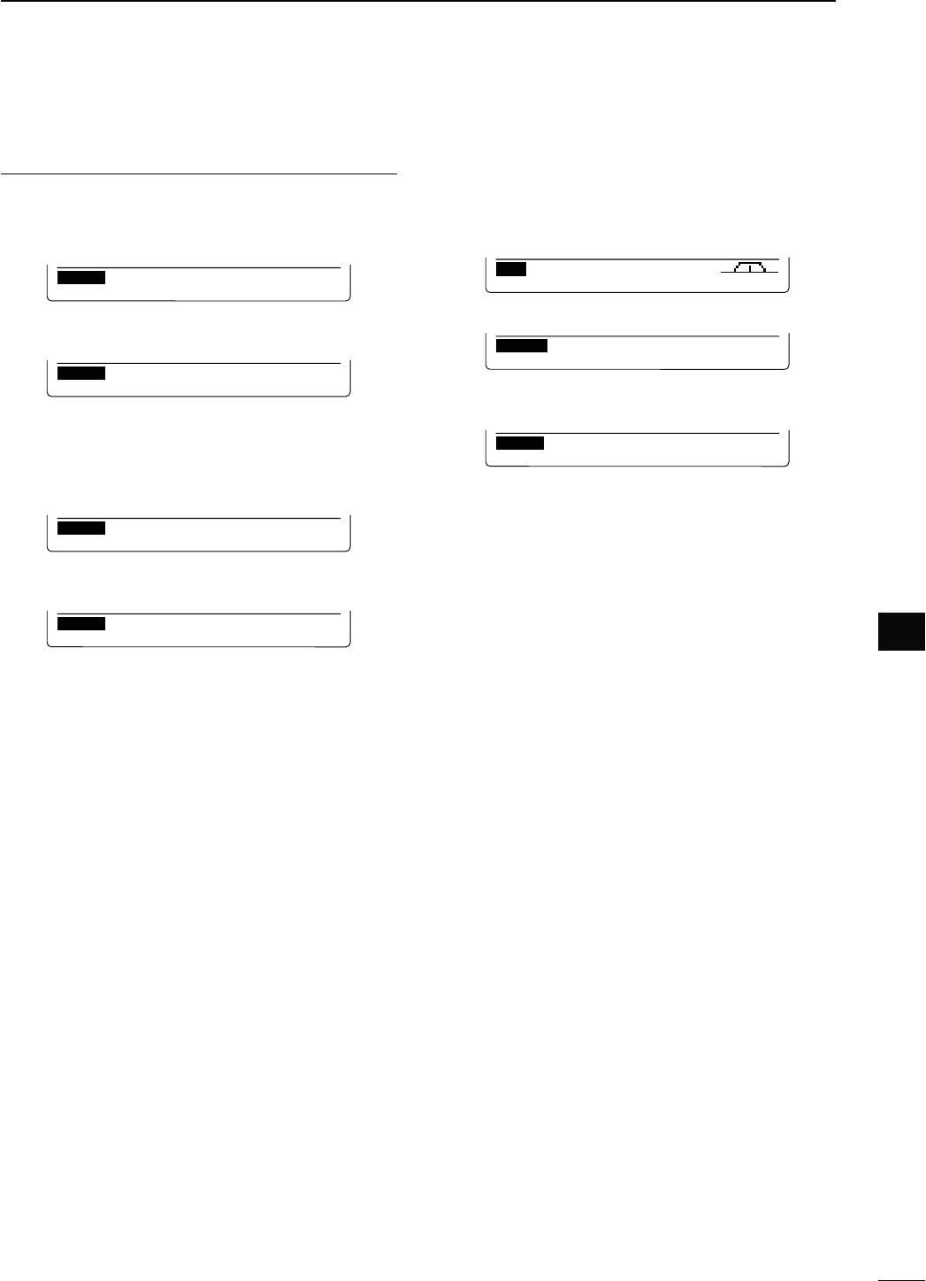
92
7
DV MODE PROGRAMMING
7
N
#LEARINGAREPEATERLIST
Contents of programmed list can be cleared (erased)
.
q Push [DVsDR] to select the DV mode.
w
P
ush [MENU] one or more times to display the “M3”
screen (Menu 3).
CS CD R>CS UR DSET
M3
e Push [DSET](F-5) to display the “DSET” screen.
DSET
TXM RP
—
L SET
r Push [RP-L](F-4) to display the “RP-L” screen (Re-
peater list).
RP–L
Repeater List
CLR ADD EDT
t
P
ush [CLR](F-3) to display the repeater list.
y Rotate [MAINDIAL] to select the desired repeater
list to be erased.
s(OLDDOWN;'20=&FORSECONDTOENTERTHE
repeater group selection mode. (“≈” moves next
to the repeater group name, and then blinks.)
Rotate [MAIN DIAL] to select the desired group (0
to 9), then push [GRP](F-5).
Or, you can select the repeater group using the
keypad key.
u Hold down [CLR](F-1) for 1 second.
s“Clear OK?” appears.
i(OLDDOWN;9%3=& to clear the selected list, and
return to the “RP-L” screen.
!FTERPROGRAMMING3.
4OADDTHEPROGRAMMEDDATAASANEWLIST
!0 Push [Z](F-2) to select the “ADD Write” item, then
hold down [WR](F-5) for 1 second.
s“ADD Write OK?” appears.
RP–L
ADD Write
ÚWRÙ
!1(OLDDOWN;9%3=&FORSECONDTOADDANEW
list, and return to the “RP-L” screen.
RP–L
ADD Write OK?
ÚYES NOÙ
4OOVERWRITETHEPROGRAMMEDDATATOTHESELECTED
LIST
!0 Push [Z](F-2) to select “OVER Write” item, then
hold down [WR](F-5) for 1 second.
s“OVER Write OK?” appears.
RP–L
OVER Write
ÚWRÙ
!1(OLDDOWN;9%3=&FORSECONDTOOVERWRITETO
the selected list, and return to the “RP-L” screen.
RP–L
OVER Write OK?
ÚYES NOÙ