ICOM orporated 318300 HF/VHF/UHF Transceiver User Manual CONFIDENTIAL ShortTerm IC 9100 UserMan
ICOM Incorporated HF/VHF/UHF Transceiver CONFIDENTIAL ShortTerm IC 9100 UserMan
Contents
- 1. User Manual 1
- 2. User Manual 2
User Manual 2
8
93
DV MODE OPERATION
N$IGITALMODEOPERATION
The IC-9100 can be operated in the digital voice mode,
including low-speed data operation, for both transmit
and receive. It can also be connected to a GPS re-
ceiver* to transmit/receive position data.
* Compatible with an RS-232 output/NMEA format/
4800bps/9600 bps
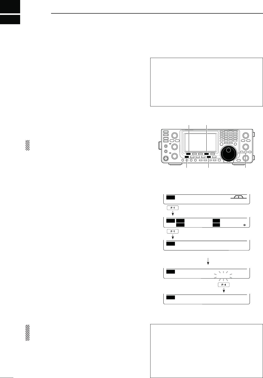
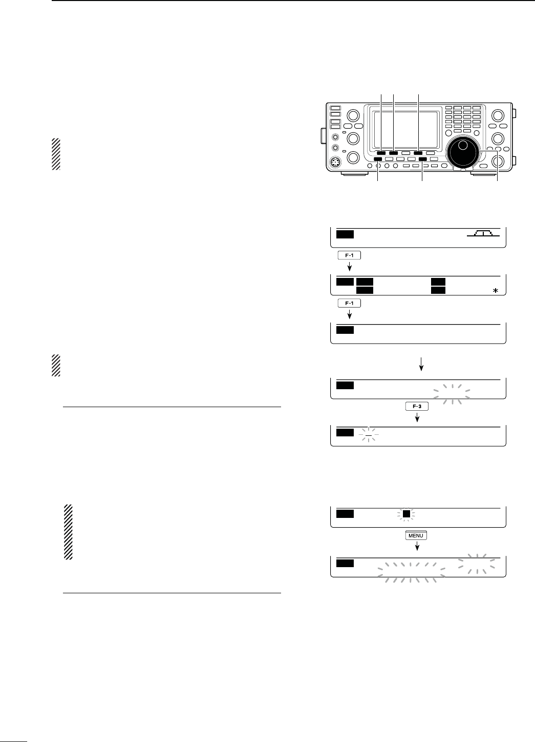
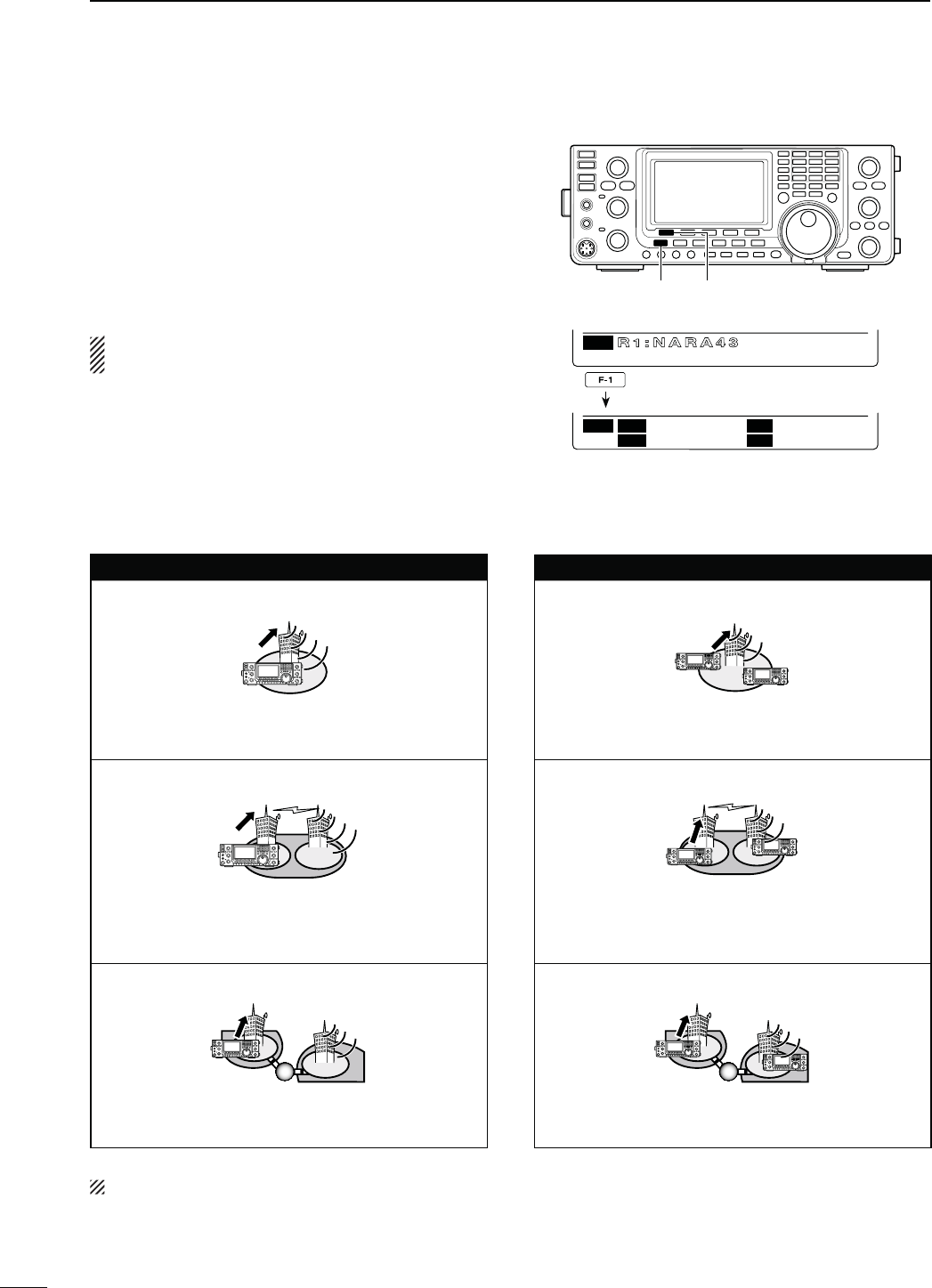
N #ALLSIGNSETTING
Set the desired h52vh2vh2vANDh-9vcall signs to
be used for DV operation, as described below.
NOTE: )NTHE$2MODEYOUCANSETONLYh-9vCALL
sign in the “CS” screen (Call Sign).
q Push [DVsDR] to select the DV mode.
w
P
ush [MENU] one or more times to display the “M3”
screen (Menu 3).
s)NTHE$2MODEP
ush [MENU] once or twice to select
the “D1” screen.
e
P
ush [CS](F-1) to display the “CS” screen (Call
Sign).
s9OUCANPUSH;&=TOTOGGLEBETWEENTHECALLSIGNAND
the name.
r
P
ush [Z](F-1) one or more times to display the
h52vh2vh2vORh-9vSCREEN
t Rotate [MAIN DIAL] to select the desired call sign.
s UR : “CQCQCQ,” individual station call signs
(U01–U99) or destination repeater call
signs*1 is selected.
s2 9OURACCESSAREAREPEATERSCALLSIGNISSE-
lected.
s R2 : “NOT USE1”*2 or a link/gateway repeater call
sign is selected.
s-99OUROWNCALLSIGNSISSELECTED-9n-9
s&IRSTSELECTINGTHECALLSIGNGROUPBYPUSHING;43s'20=
or [GRP](F-5)*3 makes it more convenient when “UR,”
“R1” or “R2” is displayed. See the right column for de-
tails of the repeater call sign group selection.
y Push [SET](F-4) to set the selected call sign to be
used for DV operation.
u Repeat steps r to y to set the other call signs.
i Push [Z](F-1) one or more times to return to the
“CS” screen.
NOTE:9OUCANTOGGLEBETWEENDISPLAYINGTHERE-
peater name or the repeater call sign by pushing
[NAME](F-4) in the R1 and R2 screens.
*1 ‘/’ is displayed in front of the repeater call sign. The
repeater call sign with ‘/’ is used for the gateway CQ
calling.
*2 For an area (local) repeater communication only
(Link repeater is not used.)
*3 [GRP](F-5) is not used in the DR mode.
[CS]/[√] [SET]
[MENU] [DV・DR] [MAIN DIAL]
CS CD R>CS UR DSET
M3
CS U
R
CQCQCQ
JA3YUA
M
Y
R
1
R
2
NOT USE
Ú
UR
UR
CLR
CQCQCQ
EDT NAME GRP
UR
UR
CLR
JG3YMK
EDT NAME GRP
UR
U01
JG3YMK
SET GRP
Rotate [MAIN DIAL]
(OWTOSELECTTHEREPEATERCALLSIGNGROUP
Hold down [TSsGRP] or [GRP](F-5)*3 for 1 second to
enter the group selection mode. Then rotate [MAIN
DIAL] to select the desired group. After selecting,
PUSH;43s'20=OR;'20=&*3 to display the re-
peater call signs in the group.
Or, you can select the repeater group using the key-
pad key.
- Only repeaters assigned to groups are selectable.
!BOUTTHE4IME/UT4IMERFUNCTION
The IC-9100 has a Time-Out Timer function for digi-
tal repeater operation. The timer limits a continuous
transmission to approximately 10 minutes. Warning
beeps will sound approximately 30 seconds before
time-out and then again immediately before time-out.
Be sure to turn ON the function before operating in
the digital mode. (p. 162)
94
8
DV MODE OPERATION
8
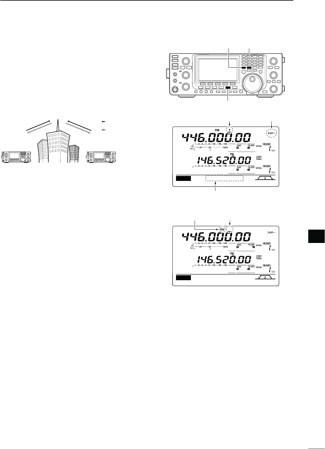
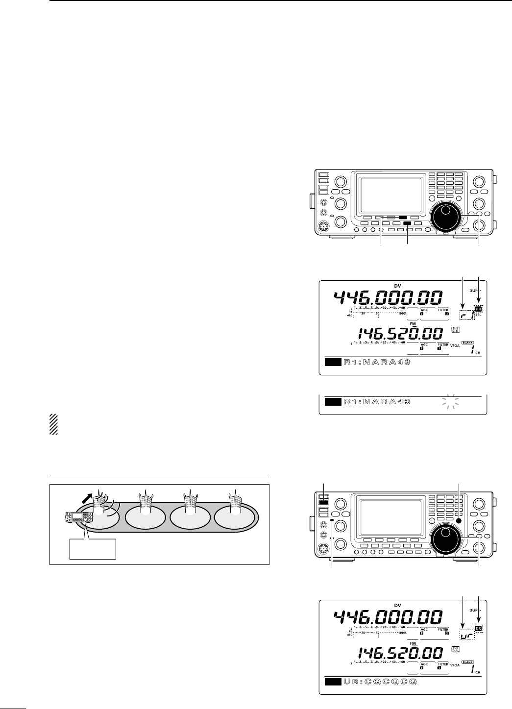
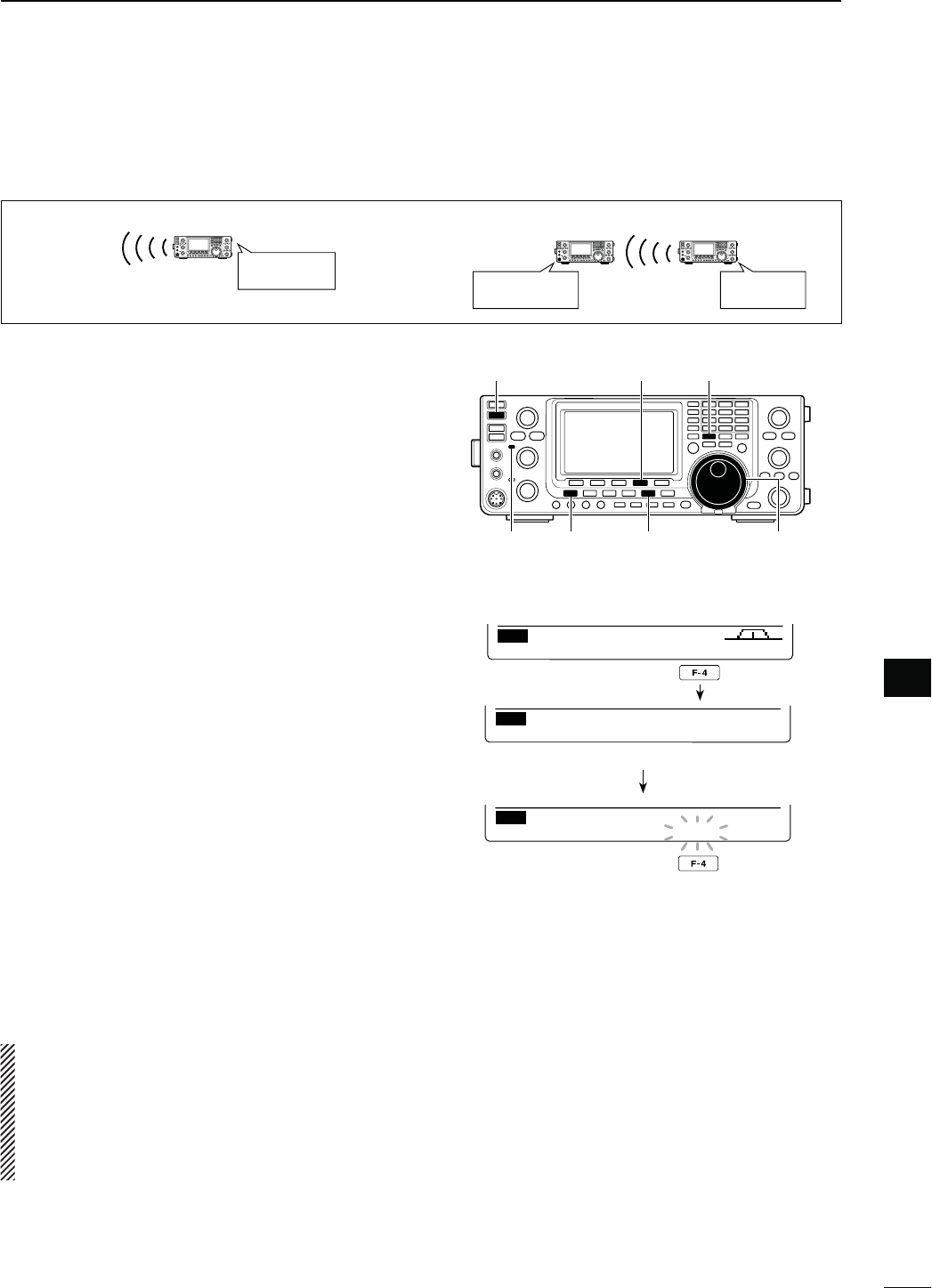
N2ECEIVINGA$34!2REPEATER
When the IC-9100 receives a signal from a D-STAR
repeater, it receives four call signs: the calling station’s
call sign, the called station’s call sign, the R1 repeater
call sign (the repeater that receives a signal from the
calling station on the uplink frequency), and the R2 re-
peater call sign (the repeater that transmits a signal
ONTHEDOWNLINKFREQUENCY9OUCANCOPYTHERECEIVED
call signs into your radio, and reply to the call.
Station A Station B
Repeater
446.000 MHz
445.400 MHz 445.400 MHz
446.000 MHz
Uplink
Downlink
(Transmit frequency)
(Receive frequency)
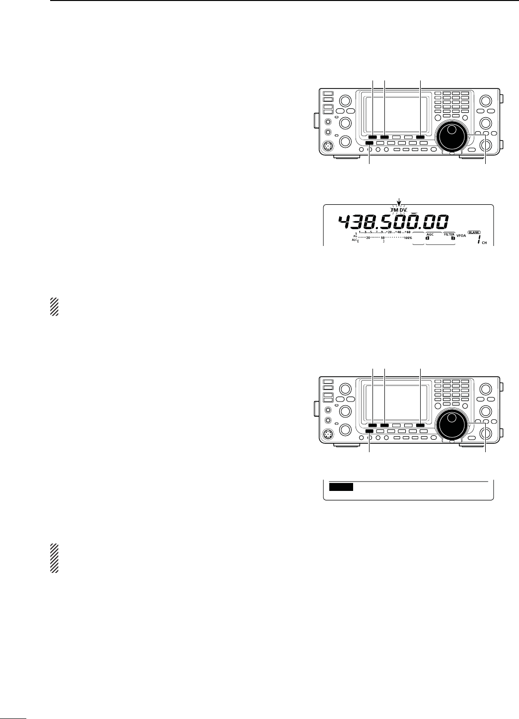
s0RESETTING
q Select the desired frequency band. (p. 35)
w Push [VFO/MEMO] to select the VFO mode.
e Push [A/B] once or twice to select VFO A.
r Set the desired repeater transmit (downlink) fre-
quency. (p. 37)
s!DJUSTTHEOUTPUTPOWERIFDESIREDP
t
P
ush [MENU] to display the “M1” screen (Menu 1).
y Hold down [DUP](F-2) for 1 second to turn ON the
One-touch repeater function.
sh4vANDh$50nvAPPEAR
s4HEREPEATERRECEIVEUPLINKFREQUENCYAPPEARSATTHE
bottom of the function display.
u Push [DUP](F-2) once or twice to switch the offset
to the desired direction.
sh$50nvORh$50vAPPEARS
s7HENTHE!UTO2EPEATERFUNCTIONISINUSETHISSELEC-
tion is not necessary (Only U.S.A. and Korean versions).
(p. 67)
i Push [DVsDR] to select the DV mode. (p. 43)
s“DV” appears.
sh4vDISAPPEARS
o When a signal is received, the calling station’s call
sign is displayed on the LCD.
s)FTHECALLINGSTATIONHASPROGRAMMEDANOTEORMES-
sage, it is displayed after the call sign.
See the next page to view the received call sign.
To reply to the calling station, see page 96.
[VFO/MEMO] [A/B]
[
DV・DR
]
“T” disappears
Appears
M1
DUPAGC AFC TON SCP
445.40000
M1
DUPAGC AFC DSQ SCP
445.40000
Appears
Uplink frequency
Appears
95
8DV MODE OPERATION
N2ECEIVEDCALLSIGNS
When a call is received in the DV mode, the calling sta-
tion and repeater call signs being used can be stored
in the received call record. The stored call signs can
be displayed in the following manner.
Up to 20 calls can be stored.
D$ESIREDCALLRECORDDISPLAY
q Push [DVsDR] to select the DV mode.
w Push [MENU] one or more times to display the “M3”
screen (Menu 3).
s)NTHE$2MODEPUSH;-%.5=ONCEORTWICETOSELECT
the “D1” screen.
e Push [CD](F-2) to display the “CD” screen (Call Re-
cord).
r Rotate [MAIN DIAL] to select the desired record
channel (RX01 to RX20).
s(OLDDOWN;#,2=&FORSECONDTOCLEARTHESELECTED
record channel.
t Push [Z](F-1) one or more times to display the call
record.
s#!,,%2 4HECALLINGSTATIONSCALLSIGN
s !FOURCHARACTERNOTEFROMTHESTATION
that made the call.
s#!,,%$ 4HECALLSIGNOFTHESTATIONTHATWAS
called, or “CQCQCQ.”
s28204 4HECALLSIGNOFTHEREPEATERTHECALL-
ing station accessed, or the call sign
of the gateway repeater the calling
station used.
s28204 4HE CALL SIGN OF THE REPEATER YOU
heard the call on.
s-3' !NYRECEIVEDMESSAGEISDISPLAYED
After the MSG screen, the date and time infor-
mation are displayed. If the received date and
time are unknown, the elapsed time after the call
was received is displayed (e.g. “(–12:34)”). If the
power is turned OFF, then ON, or 48 hours have
passed, “– – – – /– – /– – – –:– –” is displayed.
y Push [Z](F-1) one or more times to return to the
“CD” screen.
[√] [CD] [CLR]
[MENU] [DV・DR] [MAIN DIAL]
CS CD R>CS UR DSET
M3
CD
JG3YMK
CQCQCQ
RX01
CLR COPY
CD
RxRPT1
:
RxRPT2
:COPYÚ
CD
CALLER
: JG3YMK
CALLED
:
CQCQCQ
/
COPYÚ
CD
MSG
: REPEATER IS JP3
YHH A
Ú
CD
2010/10/10 10:10
Ú
96
8
DV MODE OPERATION
8
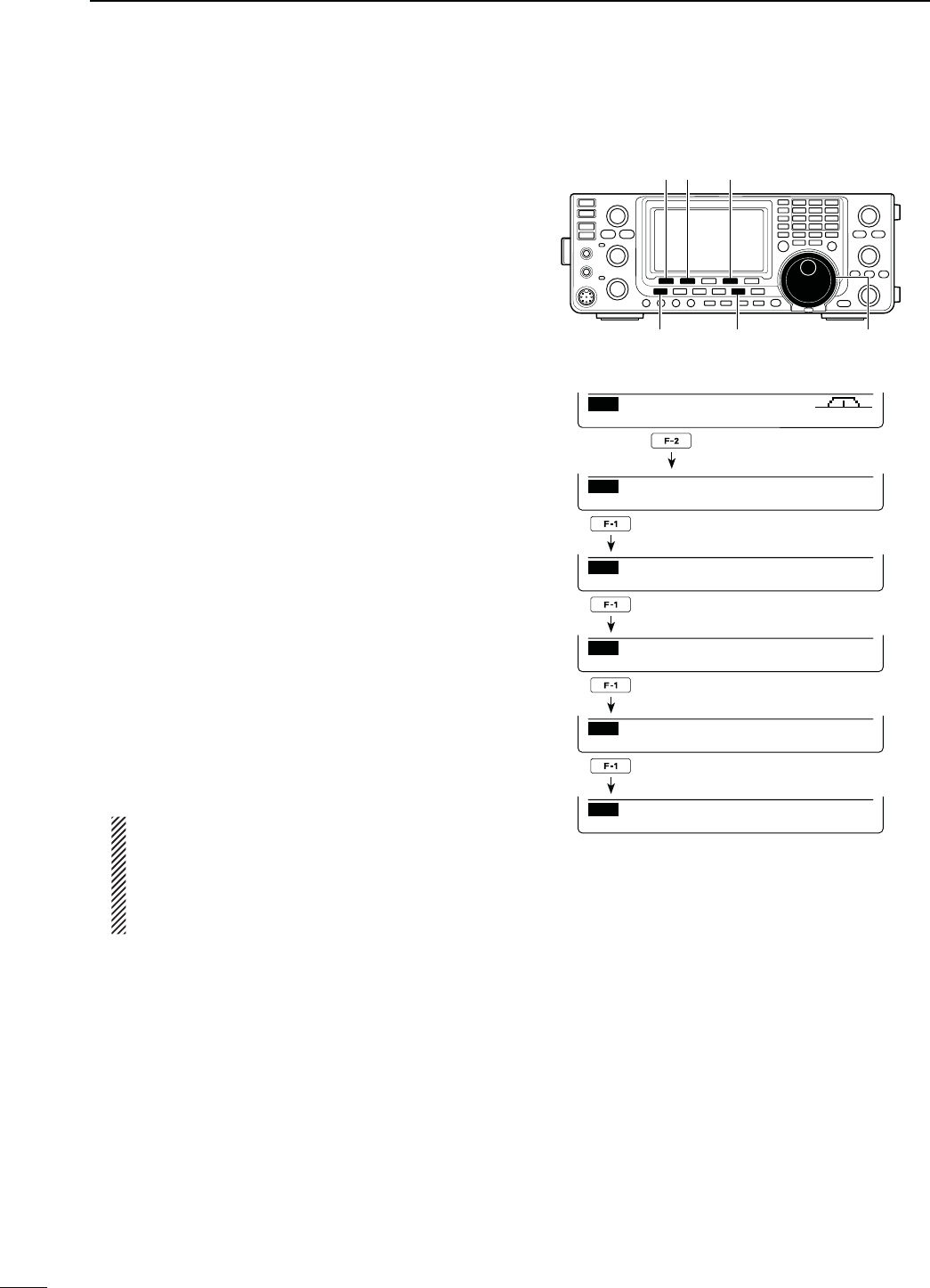
D/NETOUCHREPLYUSINGTHECALLRECORD
The calling station’s call sign, which is stored in the
call record, can be used to quickly and easily reply.
s&IRSTSETYOUROWNCALLSIGN-9P
s!FTERRECEIVINGACALL
q Push [MENU] one or more times to display the “M3”
screen (Menu 3).
s)NTHE$2MODEPUSH;-%.5=ONCEORTWICETOSELECT
the “D1” screen.
w Hold down [R>CS](F-3) for 1 second to set the
other station’s call sign.
s4HERECEIVEDCALLSIGNISDISPLAYEDWHILEHOLDINGDOWN
[R>CS](F-3), and after releasing, two beeps sound.
s7HENACALLSIGNHASNOTBEENRECEIVEDCORRECTLYERROR
beeps sound, and no call sign is set.
e Push [PTT] on the microphone to reply the call. (or
push [TRANSMIT] on the transceiver)
r Release [PTT] to receive. (or push [TRANSMIT]
again)
s3ELECTINGACALLRECORD
q Push [MENU] one or more times to display the “M3”
screen (Menu 3).
s)NTHE$2MODEPUSH;-%.5=ONCEORTWICETOSELECT
the “D1” screen.
w While holding down [R>CS](F-3), rotate [MAIN
DIAL] to select the desired record channel, then re-
lease [R>CS](F-3) to set it.
e Push [PTT] on the microphone to reply the call. (or
push [TRANSMIT] on the transceiver)
r Release [PTT] to receive. (or push [TRANSMIT]
again)
For your information
When you receive a call addressed to your own call
sign, the call signs of the calling station and the re-
peaters they used can be automatically set for a quick
reply. The set call signs are overwritten if another call
is received.
The following items must be set to “Auto” in the DV Set
mode.
These functions are not available in the DR mode.
sh28#ALL3IGN7RITEvITEMP
The calling station’s call sign is automatically set to
“UR.”
sh282047RITEvITEMP
The repeater call signs are automatically set to “R1”
and “R2,” if necessary.
[R>CS]
[MAIN DIAL]
[TRANSMIT]
CS CD R>CS UR DSET
M3
CS CD R>CS UR DSET
M3
YK/
Hold down
The received call sign is displayed while hold-
ing down [R>CS](F-3).
Important!
One-touch call signs are for only temporary use. They
are not saved in a call sign memory. Therefore, when
another call sign is set, the previous call sign will be
over-written.
If you want to save the set call sign, see ‘Copying the
call record contents into call sign memory’ for details.
(p. 98)
97
8DV MODE OPERATION
N#OPYINGTHECALLSIGN
D#OPYINGTHECALLSIGNMEMORYCONTENTS
The memorized UR call sign can be copied into an-
other call sign memory.
NOTE:
First, make sure that the “Edit Record” item is set to
“Auto” or “Select” in the DV Set mode. (p. 119)
q Push [DVsDR] to select the DV mode.
w
P
ush [MENU] one or more times to display the “M3”
screen (Menu 3).
s)NTHE$2MODEP
ush [MENU] once or twice to select
the “D1” screen.
e
P
ush [CS](F-1) to display the “CS” screen (Call
Sign).
r
P
ush [Z](F-1) to display the “UR” screen.
t Rotate [MAIN DIAL] to select the desired UR call
sign channel to be copied.
s5TO5CANBESELECTED
y
P
ush [EDT](F-3) to enter the call sign programming
mode.
s4HESTDIGITOFTHESELECTEDCALLSIGNBLINKS
The displayed contents from step u are different,
depending on the “Edit Record” item setting. (p. 119)
7HENTHEh%DIT2ECORDvITEM ISSETTOh!utov
A blank channel is automatically selected, and the
call sign channel’s data, selected in step t above,
is displayed.
u Edit the displayed call sign as described in page
86.
i Push [MENU] to store the edited call sign into
the channel.
NOTE: If there are no blank channels in the sta-
tion call sign memory, “Full” appears instead of
the channel number. In this case, follow the steps
in ‘When the “Edit record” item is set to “Select”,’
as shown below.
7HENthe h%DIT2ECORDvITEMISSETTO h3ELECTv
The selected call sign channel’s data is displayed.
u Edit the displayed call sign as described in page
86.
i Push [MENU] to set.
o Rotate [MAIN DIAL] to select the desired call
sign channel to store the data in.
!0 Hold down [SET](F-5) for 1 second to store or
overwrite the edited call sign into the selected
channel.
[√] [CD] [CLR]
[MENU] [DV・DR] [MAIN DIAL]
CS CD R>CS UR DSET
M3
CS U
R
CQCQCQ
JA3YUA
M
Y
R
1
R
2
NOT USE
Ú
UR
U06
JG3YMK
DEL SPC
UR
U01
JG3YML
(JG3YMK)
SET
UR
U01
CLR
JG3YMK
EDT GRPSET
UR
U01
JG3YM
DEL SPC
Rotate [MAIN DIAL]
UR
UR
CLR
CQCQCQ
EDT NAME GRP
When the “Edit Record” item is set to “Auto.”
When the “Edit Record” item is set to “Select.”
98
8
DV MODE OPERATION
8
This is a way to copy the call record data (“CALLER,”
“RXRPT1” and “RXRPT2”) into call sign memory “UR”
and a repeater all at the same time, or individually.
q Push [DVsDR] to select the DV mode.
w
P
ush [MENU] one or more times to display the “M3”
screen (Menu 3).
s)NTHE$2MODEPUSH;-%.5=ONCEORTWICETOSELECT
the “D1” screen.
e
P
ush [CD](F-2) to display the “CD” screen (Call Re-
cord).
r Rotate [MAIN DIAL] to select the desired record
channel (RX01 to RX20).
t
P
USH;#/09=&TOenter the copy item selection
mode.
CD
JG3YMK
CQCQCQ
RX01
CLR COPY
y Push [Y](F-1) or [Z](F-2) to select the item to be
copied.
s!,, 4HE#!,,%228204AND28204
call signs.
s#!,,%24HECALLINGSTATIONSCALLSIGN
s282044HECALLSIGNOFTHEREPEATERTHECALL-
ing station accessed, or the call sign of
the gateway repeater the calling station
used.
s282044HECALLSIGNOFTHEREPEATERYOURHEARD
the call on.
CALLER
: JG3YMK
ÚAUTO SELÙ
COPY
The options in step u are different, depending on
your selection in step y.
7HENhALLvISSELECTEDINSTEPy:
u Select the desired copy destination.
s,)34 (OLDDOWN;,)34=&FORSECOND
to automatically search a blank call
sign memory channel, then copy the
call signs of CALLER, RXRPT1 and
RXRPT2 into the channel.
s#522 (OLDDOWN;#522=&FORSECOND
to copy the call signs of CALLER,
RXRPT1 and RXRPT2 into the cur-
rent “UR,” “R1” and “R2” memory.
COPY
ALL
ÚLIST CURRÙ
7HENhCALLERvISSELECTEDINSTEPy:
u Select the desired copy destination
s!54/ (OLDDOWN;!54/=&FORSECOND
to automatically search for a blank
call sign memory channel, and copy
the selected call sign into the de-
tected one.
s3%, 0USH;3%,=&TOENTERTHECALLSIGN
memory channel selection mode.
Rotate [MAIN DIAL] to select the de-
sired channel to be pasted.
s4HECONTENTSOFTHESELECTEDCHAN-
nel is displayed in parentheses.
Holzd down [SET](F-5) for 1 second
to paste the
calling station’s call sign
into the selected channel. If a call
sign has already been programmed,
the selected channel will be overwrit-
ten.
CALLER
: JG3YMK
ÚAUTO SELÙ
COPY
UR
U01
(JG3YMK)
SET
CALLER
: JG3YMK
When “SEL” is selected, memory channel num-
ber and call sign blink.
7HENhRXRPT1vORhRXRPT2vISSELECTEDINSTEPy:
u Hold down [RP-L](F-5) to copy the repeater call
sign into the repeater list “R1” or “R2.”
COPY
RxRPT1:
ÚRP–LÙ
i After copying has been completed, transceiver au-
tomatically returns to the “CD” screen.
D#OPYINGTHECALLRECORDCONTENTSINTOCALLSIGNMEMORY
[√] [CD] [CLR]
[MENU] [DV・DR] [MAIN DIAL]
Push
99
8DV MODE OPERATION
DR (D-STAR Repeater) mode is used for D-STAR
repeater operation. In this mode, you can select the
pre-programmed repeaters and UR call sign by using
[MAIN DIAL].
s$2MODEOPERATIONmOWCHART
s2EPEATERSETTINGSCANBESTOREDINTOAREPEATERMEMORY
channel (Repeater list).
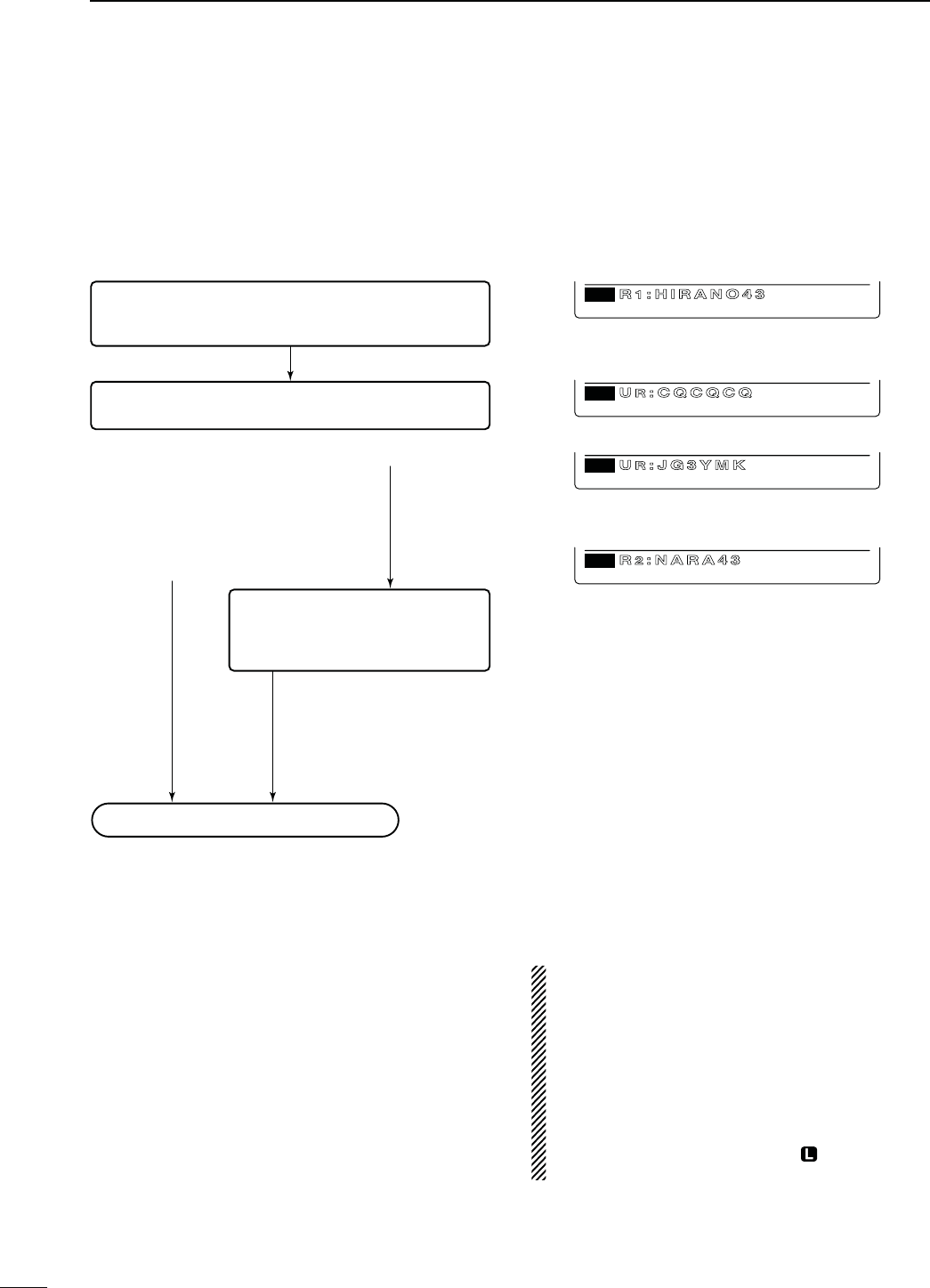
N $2$34!22EPEATERMODEOPERATION
3TEP2SELECTION
Select your access repeater.
- The Access repeater scan is useful to find a repeater.
3TEP52CALLSIGNSELECTION
Select your destination call sign
#ALLING#1
Through an access repeater
: CQCQCQ
Through a zone link repeater
or gateway repeater
: Zone link repeater or
Gateway repeater name
#ALLINGASPECIlCSTATION
3TEP2SELECTION
Select a zone link or gateway repeater.
If you make a call through an access
repeater, select “NOT USE1.”
Through an access repeater
: NOT USE1
Through a zone link repeater
: Zone link repeater name
Through a gateway repeater
: Gateway repeater name
Push PTT to transmit, release to receive.
Access/Area repeater (R1) selection
UR call sign (CQ) selection
UR call sign (specific station) selection
R2 (destination repeater) selection
GRP3
D1
RH RANO4
CS CD R>CS UR DSET
CQ
CS CD R>CS UR DSET
D1
URCQCQCQ
UR
CS CD R>CS UR DSET
D1
URJG3YMK
CS CD R>CS UR DSET
D1
RNARA4
D#OMMUNICATION&ORM
s,OCALAREACALL(pp. 101, 103)
To call a station through your local area (access) re-
peater.
s:ONECALL(pp. 102, 104)
To call a station through your local area (access) re-
peater and a link repeater in the same zone.
s'ATEWAYCALL(pp. 102, 104)
To call a station through your local area (access) re-
peater, gateway repeater and your destination repeater
by accessing the internet.
NOTE:
s Programming the repeater list is required for DR
mode operation. (pp. 89 to 92)
s9OUCANNOTMAKEAN)NTERNETCALLIFTHESELECTED
repeater (R2) has no gateway call sign.
s While operating voice communication or low-
speed data communication via the internet net-
work, some packets may be lost due to network
error (poor data throughput performance). In such
a case, the transceiver displays “ ” on the display
to indicate Packet Loss has occurred.
100
8
DV MODE OPERATION
8
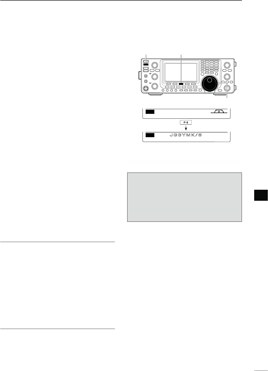
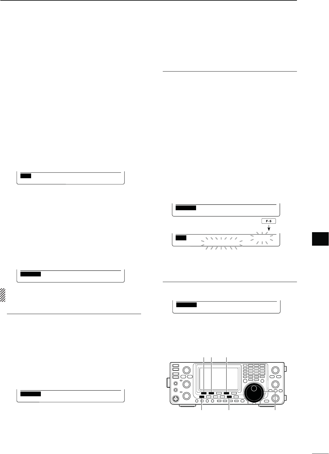
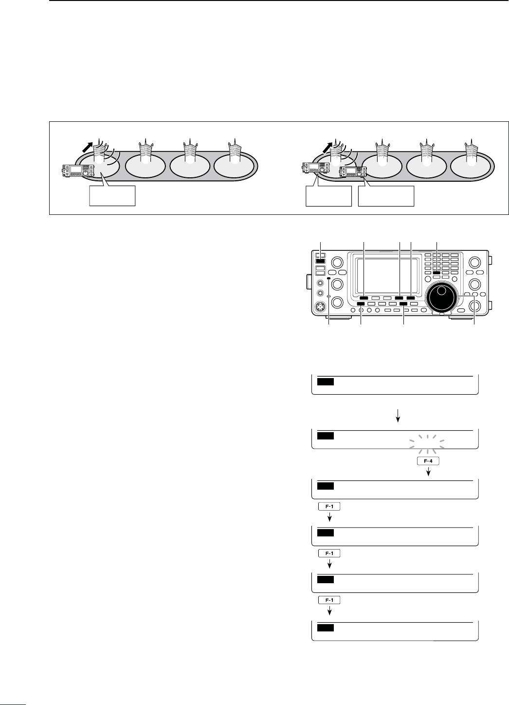
s!CCESSREPEATERSCAN’STARGETSETTING
9OUCANSELECTTHEDESIREDREPEATERSASASCANTARGET,
for faster selection and scanning.
Non-selected repeaters are skipped during scanning.
s When a repeater is specified as a non-scan target, its
“R1USE” setting is automatically set to NO. In this case,
the repeater cannot be selected as the access repeater.
(p. 90)
q In the DR mode,
p
ush [MENU] one or more times to
display the “D2” screen.
w Rotate [MAIN DIAL] to select the desired access
repeater.
s&IRSTSELECTINGTHE REPEATERCALLSIGN GROUPMAKESIT
more convenient, if you have programmed repeaters
into Groups. See the description in page 93 for details
of the repeater call sign group selection.
e Hold down [SEL](F-2) for 1 second to set the select
setting to ON.
sh3%,vAPPEARS
r Push [SEL](F-2) to set the select setting to OFF.
sh3%,vDISAPPEARS
t Push [MENU] to return to the “D2” screen.
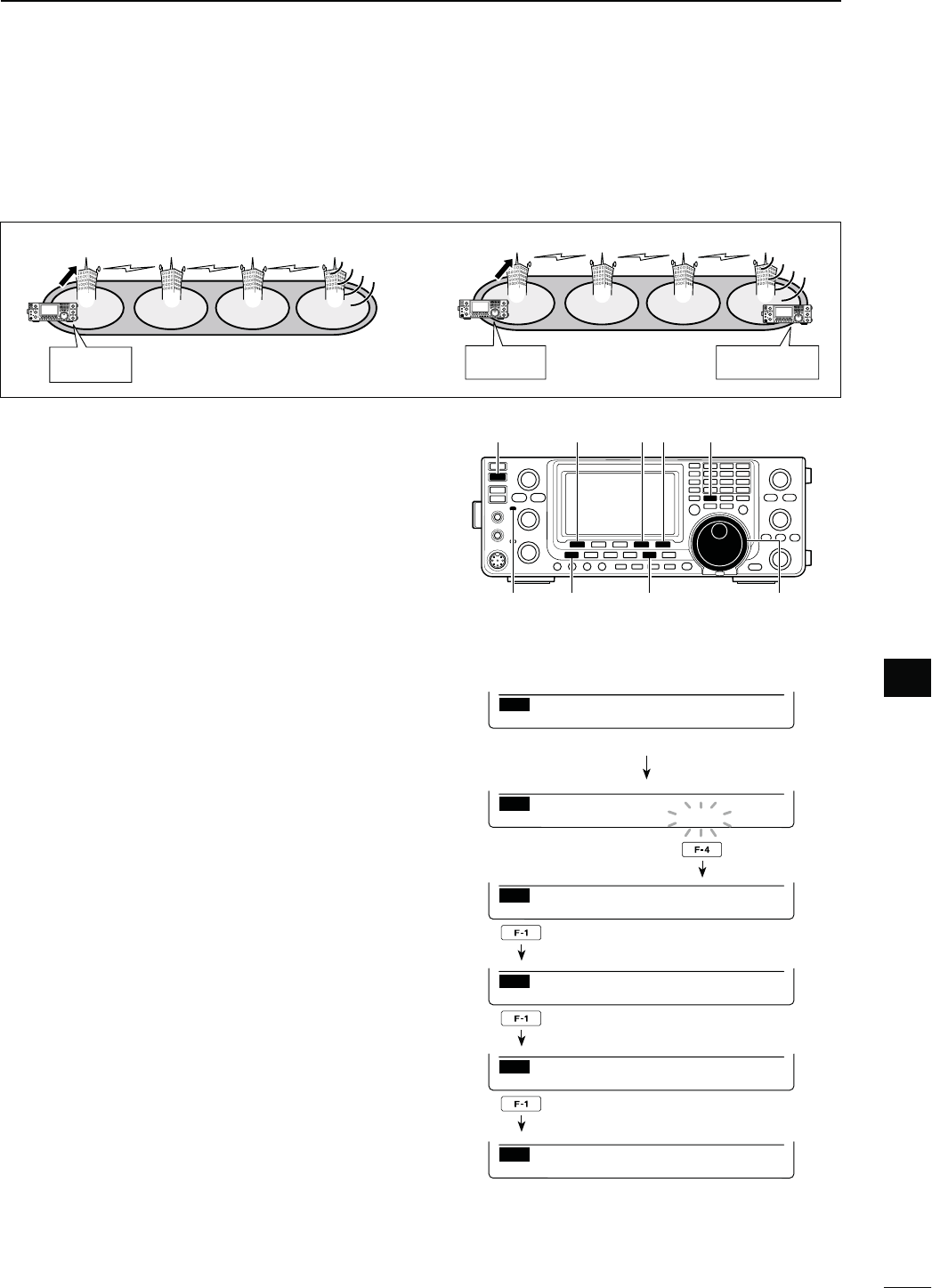
D!CCESSREPEATERSCAN
The Access repeater scan is useful to find a repeater.
For rapidly find, the Access repeater scan skips the
repeaters which are not specified as a scan target.
9OUCANSELECTTHEDESIREDREPEATERSASASCANTARGET
See page 90 or ‘Access repeater scan’s target setting’
as described below.
q Hold down [DVsDR] for 1 second to select the DR
mode.
s4HE$6MODEISAUTOMATICALLYSELECTED
sThe access repeater selection screen is displayed.
- Only the repeaters, specified as a scan target are dis-
played.
w
P
ush [MENU] one or more time to display the “D2”
screen.
e Push [SCAN](F-1) to start the Access repeater
scan.
s4HE-(ZANDK(ZDECIMALPOINTSANDh ” blink while
scanning.
s(OLDDOWN;3#!.=&FORSECONDTOENTERTHE3CAN
set mode. Push [MENU] to exit the Scan set mode.
- If
“Up/Down” is selected as
the “MAIN DIAL (SCAN)”
option
in the Scan Set mode, rotating [MAIN DIAL]
changes the scanning direction. (p. 147)
s4HESCANPAUSESWHENASIGNALISRECEIVED
r Push [SCAN](F-1) to cancel the scan.
[D
[MAIN DIAL]
[D[MENU]
[SEL]
GRP
SCAN SEL A FC DSQ TCON
D2
GRP3
SCAN SEL A FC DSQ TCON
D2
RHIRANO4
GRP1
SCAN SEL A FC DSQ TCON
D2
RFUJ SW4
GRP1
SEL
D2
FU ISW4
SEL
GRP1
SEL
D2
FU ISW4
When the select setting is OFF.
GRP1
SCAN SEL A FC DSQ TCON
D2
RHAMACH 3
Rotate [MAIN DIAL]
Hold down
Push
While Access repeater scanning
101
8DV MODE OPERATION
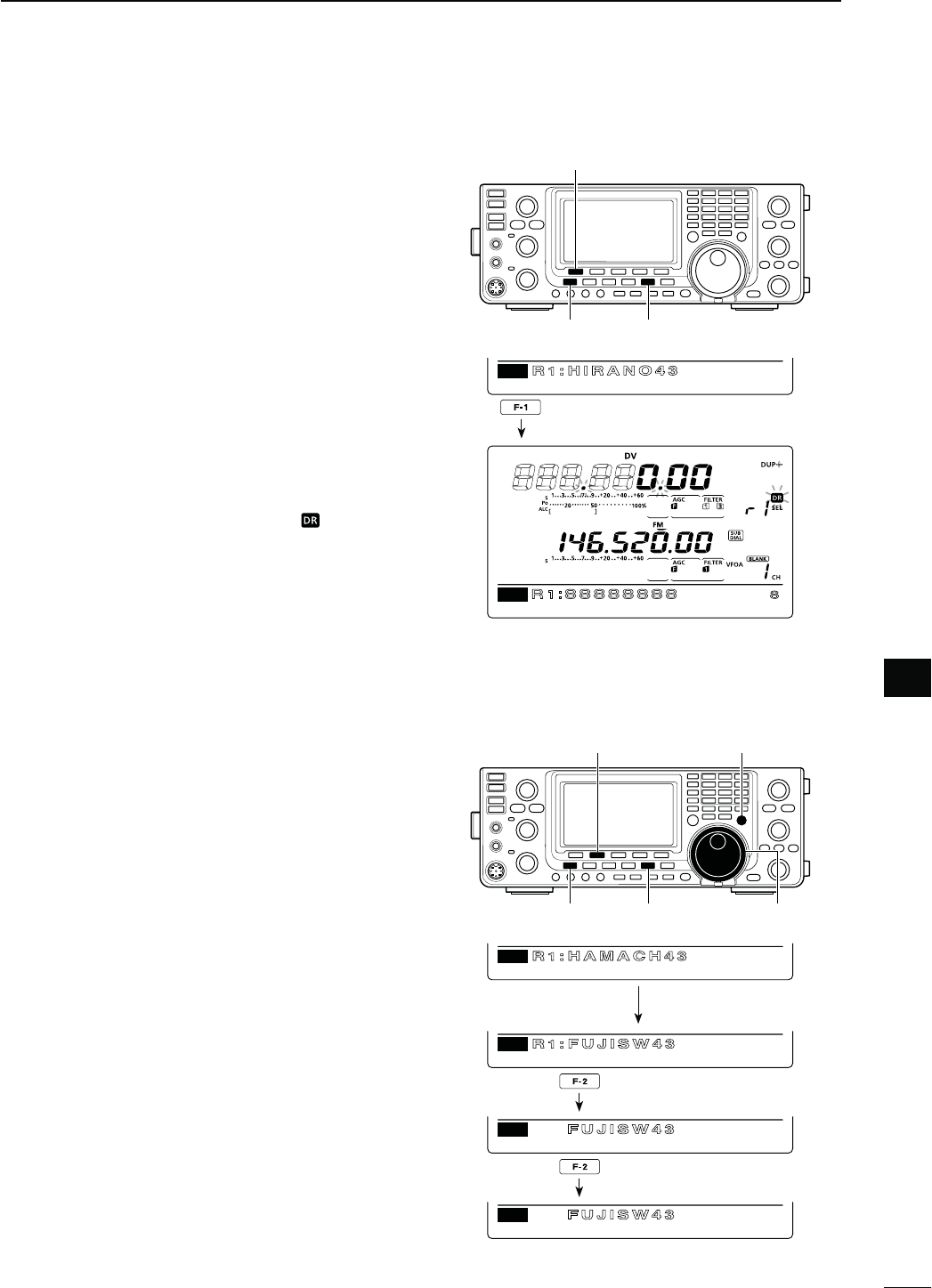
N#ALLING#1
&IRSTPROGRAMA-9CALLSIGNINSTEPq.
Next program the repeater list (p. 89). After that, follow
this guide to access a D-STAR repeater.
The optional CS-9100* cloning software is helpful for
programming call signs and programming the repeater
list.
*Cloning cable is required.
q3ETYOUROWNCALLSIGN-9(p. 85)
w Hold down [DVsDR] for 1 second to select the DR
mode.
sThe last used access repeater is displayed.
- If the displayed frequency band on the SUB Band is
the same as that of the last used access repeater, se-
lecting the DR mode on the MAIN Band will automati-
cally move the frequency band on the SUB Band to
the Main Band display, and turn OFF the SUB Band
display.
e Rotate [MAIN DIAL] to select the desired access
repeater.
s/NLYTHEREPEATERS, whose “R1USE” setting is set to
9%3OR!CCESSREPEATERSCANTARGETS are displayed.
(pp. 90, 100)
s&IRSTSELECTINGTHE REPEATERCALLSIGN GROUPMAKESIT
more convenient, if you have programmed repeaters
into Groups. (p. 93)
s!CCESSREPEATERSCANCANBEUSEDFORTHESELECTION
(p. 100)
r Push [UR](F-4) to enter the UR call sign selection
mode.
Steps t through u differ, depending on the com-
munication form.
CS CD R>CS UR DSET
D1
GRP3
RNARA43
CS CD R>CS UR DSET
D1
UR
UCQCQCQ
[MAIN DIAL]
[D
Access repeater selection screen
UR call sign selection screen
Repeater group selection screen
Appears
GRP3
CS CD R>CS UR DSET
D1
RNARA4
Appear
[TRANSMIT] [
[MAIN DIAL]
MAIN Band TX/RX indicator
-AKINGA#1CALLTHROUGHYOURLOCALAREAACCESS
REPEATER,OCAL!REA#1
My call sign:
JA3YUA
CQ
Area
Zone
Repeater q: NARA43 (JP3YHL)
q w e r
t Rotate [MAIN DIAL] to select “CQCQCQ.”
s&IRSTSELECTINGACALLSIGNGROUPAS“CQCQCQ” by push-
ING;43s'20=MAKESITMORECONVENIENT
y Push [PTT] on the microphone to transmit. (or
[TRANSMIT] on the transceiver)
s4HE-!)."AND4828INDICATORLIGHTSRED
u Release [PTT] to receive. (or push [TRANSMIT]
again)
102
8
DV MODE OPERATION
8
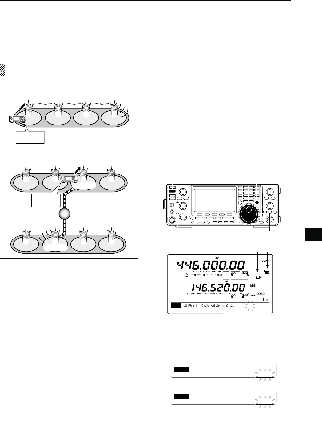
-AKINGA:ONE#1'ATEWAY#1CALL
NOTE: The settings are the same between Zone
CQ and Gateway CQ call.
CS CD R>CS UR DSET
D1
GRP3
UIKOMA 3
Repeater selection screen
Appear
[TRANSMIT] [
[MAIN DIAL]
MAIN Band TX/RX indicator
The selected channel number blinks.
When a blank channel is selected.
()1ch
ARAS
CQCQ
MW
DV446.00000
( ) 5ch
MW
—————————
.
—————
D3TORINGTHESETDATA
9OU CANSAVETHE TEMPORARYSETTINGINTHE FOLLOWING
manner.
q After setting,
push
[MW] to enter the memory select
write mode
, then rotate [MAIN DIAL] or [M-CH] to
select the desired Memory channel, Call channel or
Program scan edge channel.
w
H
old down [MW] again for 1 second
to store the set-
ting.
t Rotate [MAIN DIAL] to select a desired destination
repeater.
s&IRSTSELECTINGTHE REPEATERCALLSIGN GROUPMAKESIT
more convenient, if you have programmed repeaters
into Groups. (p. 93)
y Push [PTT] on the microphone to transmit. (or
[TRANSMIT] on the transceiver)
s4HE-!)."AND4828INDICATORLIGHTSRED
u Release [PTT] to receive. (or push [TRANSMIT]
again)
s#ALLING#1THROUGHALINKREPEATERINTHESAME
ZONE:ONE#1
My call sign:
JA3YUA
Repeater q : NARA43 (JP3YHL)
Repeater r : IKOMA43 (JP3YHJ)
CQ
q w e r
Area
Zone
s
#ALLING#1THROUGHAGATEWAYREPEATER'ATEWAY
#1
Repeater e :
Repeater y :
CQ
q w e r
t y u i
MY call sign:
JA3YUA
Gateway
Gateway
Area
Zone A
Zone B
HIRANO43
(JP3YHH)
IcomUSA
(N7IH)
103
8DV MODE OPERATION
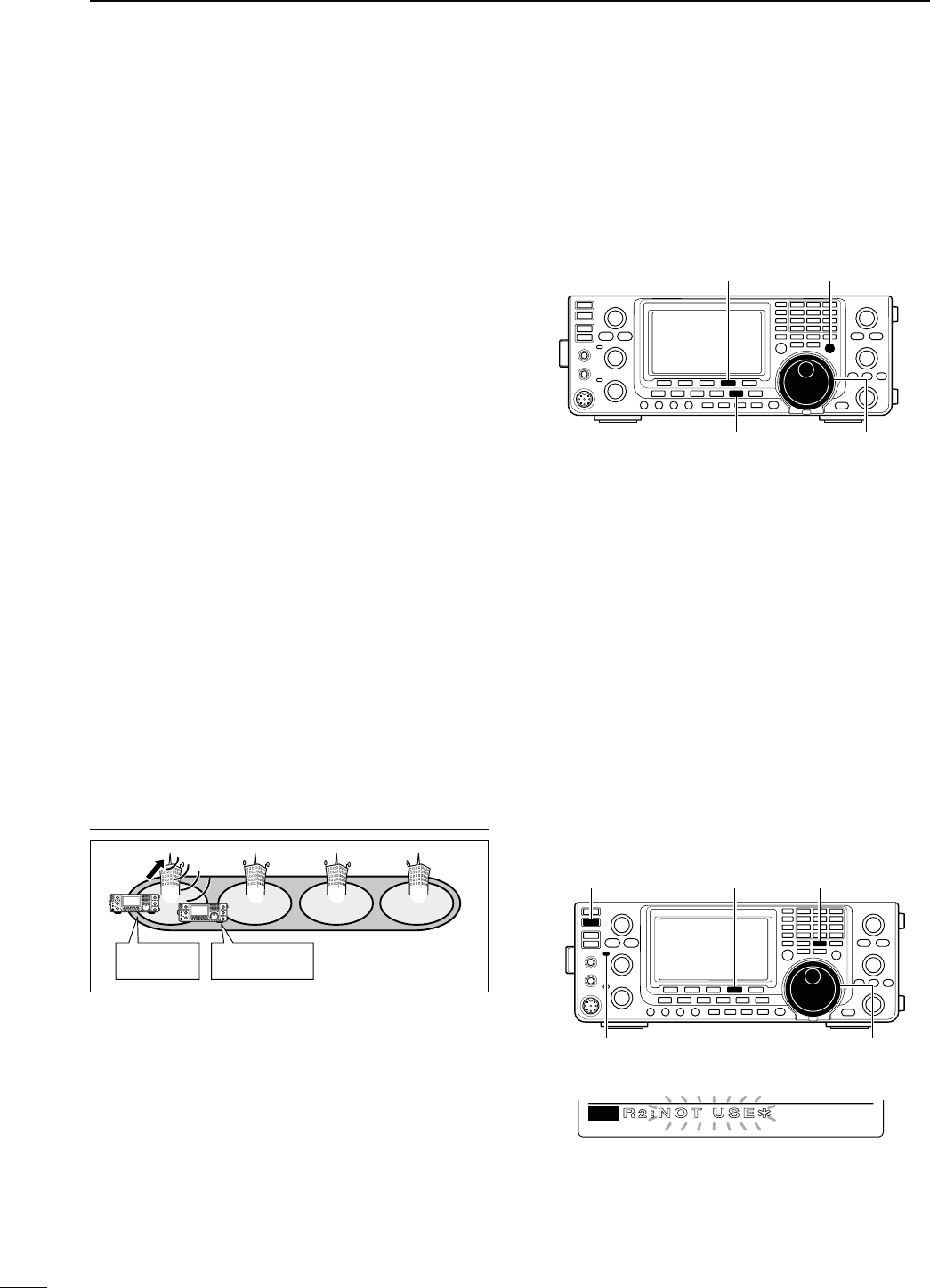
N#ALLINGASPECIlCSTATION
This section describes how to call a specific station
using the DR mode.
When the Link repeater (R2) is set to “GW,” the des-
ignated gateway repeater is automatically set as the
Link repeater, and you can make a call to a specific
station through the internet.
q Set your own call sign.
w Hold down [DVsDR] for 1 second to select the DR
mode.
sThe last used access repeater is displayed.
- If the displayed frequency band on the SUB Band is
the same as that of the last used access repeater, se-
lecting the DR mode on the MAIN Band will automati-
cally move the frequency band on the SUB Band to
the Main Band display, and turn OFF the SUB Band
display.
e Rotate [MAIN DIAL] to select the desired access
repeater.
s/NLYTHEREPEATERS, whose “R1USE” setting is set to
9%3OR!CCESSREPEATERSCANTARGETS are displayed.
(pp. 90, 100)
r Push [UR](F-4) to enter the UR call sign selection
mode.
t Rotate [MAIN DIAL] to select a individual station
call sign.
s&IRST SELECTING THE station call sign memory groups
(U01–U99)BYPUSHING;43s'20=MAKESITMORECONVE-
nient.
y Hold down [UR](F-4) for 1 second to enter the Link/
Gateway repeater (R2) selection mode.
-AKINGACALLTOANINDIVIDUALSTATIONTHROUGHYOUR
LOCALAREAACCESSREPEATER,OCAL!REACALL
MY call sign:
JA3YUA
Station call sign:
JG3YMK
Repeater q : NARA43
(JP3YHL)
q w e r
Area
Zone
u Rotate [MAIN DIAL] to select “NOT USE1.”
i Push [UR](F-4) to exit the Link repeater (R2) selec-
tion mode.
o Push [PTT] on the microphone to transmit. (or
[TRANSMIT] on the transceiver)
s4HE-!)."AND4828INDICATORLIGHTSRED
!0 Release [PTT] to receive. (or push [TRANSMIT]
again)
s!FTERTRANSMITTINGPUSH;-7=TOENTERTHEMEMORYSE-
lect write mode. (p. 102)
[MAIN DIAL]
[D
]
NOT USE1
CS CD R>CS UR DSET
D1
R2:NOT US
[TRANSMIT] [UR] [MW]
[MAIN DIAL]
MAIN Band TX/RX indicator
104
8
DV MODE OPERATION
8
Link repeater in the same zone
CS CD R>CS UR DSET
D1
R2IKOMA 4
Gateway repeater “GW”
CS CD R>CS UR DSET
D1
R2GW
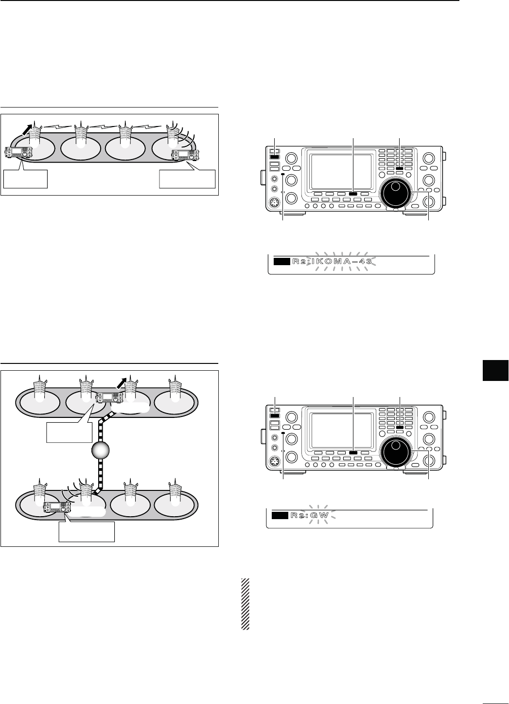
-AKING A CALL TO AN INDIVIDUAL STATION THROUGH A
LINKREPEATERINTHESAMEZONE:ONECALL
MY call sign:
JA3YUA
Station call sign:
JG3YMK
Repeater q : NARA43 (JP3YHL)
Repeater r : IKOMA-43 (JP3YHJ)
q w e r
Area
Zone
u Rotate [MAIN DIAL] to select the link repeater in
the same zone.
s/NLYREPEATERSWITHTHESAME GATEWAY REPEATERAP-
pear.
i Push [UR](F-4) to exit the selection mode.
i Push [PTT] on the microphone to transmit. (or
[TRANSMIT] on the transceiver)
s4HE-!)."AND4828INDICATORLIGHTSRED
!0 Release [PTT] to receive. (or push [TRANSMIT]
again)
s!FTERTRANSMITTINGPUSH;-7=TOENTERTHEMEMORYSE-
lect write mode. (p. 102)
-AKING A CALL TO AN INDIVIDUAL STATION
THROUGH A
GATEWAYREPEATER'ATEWAYCALL
Repeater e :
Repeater y :
HIRANO43
(JP3YHH G)
HAMA43
(JP1YIU G)
Gateway
Gateway
Area
Zone A
Zone B
q w e r
t y u i
MY call sign:
JA3YUA
Station call sign:
JM1ZLK
u Rotate [MAIN DIAL] to select “GW.”
s4HEPREPROGRAMMEDGATEWAYREPEATERISSETAS2
s/NLYREPEATERSWITHTHESAME GATEWAY REPEATERAP-
pear.
i Push [UR](F-4) to exit the Link repeater (R2) selec-
tion mode.
o Push [PTT] on the microphone to transmit. (or
[TRANSMIT] on the transceiver)
s4HE-!)."AND4828INDICATORLIGHTSRED
!0 Release [PTT] to receive. (or push [TRANSMIT]
again)
s!FTERTRANSMITTINGPUSH;-7=TOENTERTHEMEMORYSE-
lect write mode. (p. 102)
[TRANSMIT] [UR] [MW]
[MAIN DIAL]
MAIN Band TX/RX indicator
NOTE: If other station has accessed a repeater at
least once, the D-STAR system will automatically
connect to the last repeater the station accessed,
even if you don’t know where the station is. So it is
no need to select the destination repeater.
[TRANSMIT] [UR] [MW]
[MAIN DIAL]
MAIN Band TX/RX indicator
105
8DV MODE OPERATION
N Calling a specific station (Continued)
D#ONlRMINGTHESETTING
q In the DR mode,
p
ush [MENU] one or more times to
display the “D1” screen.
w
P
ush [CS](F-1) to display the “CS” screen (Call
Sign).
e
P
ush [Z](F-1) one or more times to sequentially
DISPLAYTHEh52vh2vh2vORh-9vTOCONlRMTHE
current call sign setting.
NOTE: In the DR mode, you can change only the
h-9vCALLSIGNINTHE“CS” screen (Call Sign).
[CS]/[Z][MENU]
CS U
RJG3YMK
JA3YUA
M
Y
R
1JP3YHL
R
2JP3YHJ
Ú
GRP3
D1
RNA A4
CS CD R>CS UR DSET
D3ETTINGSFOR“UR”AND“2”DEPENDINGONTHECOMMUNICATIONFORM
$ESTINATION#1 $ESTINATION!NINDIVIDUALSTATION
#OMMUNICATIONFORM,OCALAREACALL
CQ
s52SETTING#1#1#1
s2SETTING.!
#OMMUNICATIONFORM,OCALAREACALL
s52SETTING!NINDIVIDUALSTATION
s2SETTING./453%1
#OMMUNICATIONFORM:ONECALL
CQ
s52SETTING$ESTINATIONREPEATERTOSEND#1IN
the same zone
s2SETTING.!
#OMMUNICATIONFORM:ONECALL
s52SETTING!NINDIVIDUALSTATION
s2SETTING$ESTINATION REPEATER IN THE SAME
zone
#OMMUNICATIONFORM'ATEWAYCALL
CQ
s52SETTING$ESTINATIONREPEATERTOSEND#1
s2SETTING.!
#OMMUNICATIONFORM'ATEWAYCALL
s52SETTING!NINDIVIDUALSTATION
s2SETTING'7
NOTE: R1 setting is set to your access repeater’s call sign.
106
8
DV MODE OPERATION
8
s#ALLING#1
MY call sign:
JA3YUA
CQ
s#ALLINGANINDIVIDUALSTATION
My call sign:
JA3YUA
Station call sign:
JG3YMK
[TRANSMIT]
MAIN Band
TX/RX indicator
[MAIN DIAL]
[D[MENU]
[VFO/MEMO][UR]/[SET]
CS CD R>CS UR DSET
M3
UR
UR
JG3LUK
GRP
UR
CQCQCQ
SET GRP
U––
Rotate [MAIN DIAL]
s7HENCALLING#1
q Select the desired frequency band. (p. 35)
w Push [VFO/MEMO] to select the VFO mode.
e Push [DVsDR] to select the DV mode.
r Set the desired frequency. (p. 37)
s3ELECTTHEOUTPUTPOWERIFDESIREDP
sWhen the duplex operation is selected, push [MENU]
one or more times to display the “M1” screen (Menu 1)
and push [DUP](F-2) one or more times to turn it OFF.
t Push [MENU] twice to display the “M3” screen
(Menu 3).
y3ETYOUROWNCALLSIGNASTHECURRENT-9CALLSIGN
(p. 85)
u Push [UR](F-4) to enter the UR call sign selection
mode.
i Rotate [MAIN DIAL] to select UR call sign.
s&IRSTSELECTINGTHECALLSIGNMEMORYGROUPSBYPUSHING
;43s'20=OR;'20=&MAKESITMORECONVENIENT
s When calling CQ : Select “CQCQCQ”
s When calling an individual station
: Select the station’s call sign
o Push [SET](F-4) to return to the “M3” screen (Menu
3).
!0 Push [PTT] on the microphone to transmit. (or
[TRANSMIT] on the transceiver)
s4HE-!)."AND4828INDICATORLIGHTSRED
!1 Release [PTT] to receive. (or push [TRANSMIT]
again)
s)FANOTHERSTATIONREPLIESITSCALLSIGNWILLBERECEIVED
s2ECEIVEDCALLSIGNSCANBEAUTOMATICALLYSTOREDINTOTHE
received call record. See page 95 for details.
s!FTERTRANSMITTINGROTATE;-#(=TOSELECTAMEMOR
y
channel, then hold down [MW] for 1
second to save this
temporary programmed data into the channel.
NOTE: The digital mode is vastly different than the
FM mode. One of the differences is that changing
the squelch setting in the digital mode will not open
it to hear the hiss of “white noise,” like it does in the
FM mode. It is only activated for digital squelch func-
tions such as CSQL (Digital code squelch) or DSQL
(Digital call sign squelch).
N 3IMPLEXOPERATIONUSINGTHE6&/
D-AKINGASIMPLEX#1CALLORACALLTOANINDIVIDUALSTATION
107
8DV MODE OPERATION
s#ALLING#1
My call sign:
JA3YUA
CQ
Area
Zone
Repeater q: JP3YHL
q w e r
s#ALLINGANINDIVIDUALSTATION
My call sign:
JA3YUA
Station call sign:
JG3YMK
Repeater q : JP3YHL
q w e r
Area
Zone
N 2EPEATEROPERATIONUSINGTHE6&/
D-AKINGA#1CALLORACALLTOANINDIVIDUALSTATIONTHROUGHYOURLOCALAREAACCESSRE-
PEATER,OCAL!REACALL
[TRANSMIT]
MAIN Band
TX/RX indicator
[MAIN DIAL]
[D[MENU]
[VFO/MEMO][SET][Z] [GRP]
UR
UR
CLR
JG3YMK
EDT NAME GRP
R1
R1
CLR
JP3YHL
EDT NAME GRP
UR
U01
CQCQCQ
SET GRP
Rotate [MAIN DIAL]
R2
R2
CLR EDT NAME GRP
MY
MY1
CLR
JA3YUA ⁄
EDT NAME
UR
UR
CLR
CQCQCQ
EDT NAME GRP
s7HENCALLING#1THROUGHASINGLEREPEATER
q Select the desired frequency band. (p. 35)
w Push [VFO/MEMO] to select the VFO mode.
e Push [DVsDR] to select the DV mode.
r Set the repeater’s transmit frequency, duplex direc-
tion and offset. (pp. 37, 65, 163)
t
P
ush [MENU] one or more times to display the “M3”
screen (Menu 3).
y
P
ush [CS](F-1) to display the “CS” screen (Call
Sign).
u
P
ush [Z](F-1) to display the “UR” screen, and rotate
[MAIN DIAL] to select UR call sign, then push [SET]
(F-4).
s&IRSTSELECTINGTHECALLSIGNMEMORYGROUPSBYPUSHING
;43s'20=OR;'20=&MAKESITMORECONVENIENT
s When calling CQ : Select “CQCQCQ”
s When calling an individual station
: Select the station’s call sign
i
P
ush [Z](F-1) to display the “R1” screen, and rotate
[MAIN DIAL] to select the access repeater call sign,
then push [SET](F-4).
s&IRSTSELECTINGTHE REPEATERCALLSIGN GROUPMAKESIT
more convenient, if you have programmed repeaters
into Groups. (p. 93)
s0USH;.!-%=&TOTOGGLETHECALLSIGNANDREPEATER
name display, if the name has been programmed.
o
P
ush [Z](F-1) to display the “R2” screen, and rotate
[MAIN DIAL] to set R2 to “NOT USE1,” then push
[SET](F-4).
!0
P
ush [Z](F-1) TODISPLAYh-9vANDSETYOUROWNCALL
sign if necessary, then push [SET](F-4).
!1 Push [PTT] on the microphone to transmit. (or
[TRANSMIT] on the transceiver)
s4HE-!)."AND4828INDICATORLIGHTSRED
!2 Release [PTT] to receive. (or push [TRANSMIT]
again)
s)FANOTHERSTATIONSREPLIESITSCALLSIGNWILLBESTOREDIN
the receive log.
s2ECEIVEDCALLSIGNSCANBEAUTOMATICALLYSTOREDINTOTHE
received call record. See page 95 for details.
s!FTERTRANSMITTINGROTATE;-#(=TOSELECTAMEMORY
channel, then hold down [MW] for 1 second to save this
temporary programmed data into the channel.
108
8
DV MODE OPERATION
8
s#ALLING#1
My call sign:
JA3YUA
Repeater q : JP3YHL
Repeater r : JP3YHJ
CQ
q w e r
Area
Zone
s#ALLINGANINDIVIDUALSTATION
My call sign:
JA3YUA
Station call sign:
JG3YMK
Repeater q : JP3YHL
Repeater r : JP3YHJ
q w e r
Area
Zone
[TRANSMIT]
MAIN Band
TX/RX indicator
[MAIN DIAL]
[D[MENU]
[VFO/MEMO][SET][Z] [GRP]
UR
UR
CLR
JG3YMK
EDT NAME GRP
R1
R1
CLR
JP3YHL
EDT NAME GRP
UR
U01
CQCQCQ
SET GRP
Rotate [MAIN DIAL]
R2
R2
CLR
JP3YHJ
EDT NAME GRP
MY
MY1
CLR
JA3YUA ⁄
EDT NAME
UR
UR
CLR
CQCQCQ
EDT NAME GRP
s#ALLING#1 INTHESAMEZONE:ONE#1
q Select the desired frequency band. (p. 35)
w Push [VFO/MEMO] to select the VFO mode.
e Push [DVsDR] to select the DV mode.
r Set the repeater’s transmit frequency, duplex direc-
tion and offset. (pp. 37, 65, 163)
t
P
ush [MENU] one or more times to display the “M3”
screen (Menu 3).
y
P
ush [CS](F-1) to display the “CS” screen (Call
Sign).
u
P
ush [Z](F-1) to display the “UR” screen, and rotate
[MAIN DIAL] to select UR call sign, then push [SET]
(F-4).
s&IRSTSELECTINGTHECALLSIGNMEMORYGROUPSBYPUSHING
;43s'20=OR;'20=&MAKESITMORECONVENIENT
s When calling CQ : Select “CQCQCQ”
s When calling an individual station
: Select the station’s call sign
i
P
ush [Z](F-1) to display the “R1” screen, and rotate
[MAIN DIAL] to select the access repeater call sign,
then push [SET](F-4).
s&IRSTSELECTINGTHE REPEATERCALLSIGN GROUPMAKESIT
more convenient, if you have programmed repeaters
into Groups. (p. 93)
s0USH;.!-%=&TOTOGGLETHECALLSIGNANDREPEATER
name display, if the name has been programmed.
o
P
ush [Z](F-1) to display the “R2” screen, and rotate
[MAIN DIAL] to select the link repeater call sign in
the same zone, then push [SET](F-4).
!0
P
ush [Z](F-1) TODISPLAYh-9vANDSETYOUROWNCALL
sign if necessary, then push [SET](F-4).
!1 Push [PTT] on the microphone to transmit. (or
[TRANSMIT] on the transceiver)
s4HE-!)."AND4828INDICATORLIGHTSRED
!2 Release [PTT] to receive. (or push [TRANSMIT]
again)
s)FANOTHERSTATIONSREPLIESITSCALLSIGNWILLBESTOREDIN
the receive log.
s2ECEIVEDCALLSIGNSCANBEAUTOMATICALLYSTOREDINTOTHE
received call record. See page 95 for details.
s!FTERTRANSMITTINGROTATE;-#(=TOSELECTAMEMORY
channel, then hold down [MW] for 1 second to
save this
temporary programmed data
into the channel.
D-AKINGA#1CALLORACALLTOANINDIVIDUALSTATIONTHROUGHALINKREPEATERINTHESAME
ZONE:ONECALL
109
8DV MODE OPERATION
q Select the desired frequency band. (p. 35)
w Push [VFO/MEMO] to select the VFO mode.
e Push [DVsDR] to select the DV mode.
r Set the repeater’s transmit frequency, duplex direc-
tion and offset. (pp. 37, 65, 163)
t Push [MENU] one or more times to display the “M3”
screen (Menu 3).
y
Push [CS](F-1) to display the “CS” screen (Call Sign).
u Push [Z](F-1) to display the “UR” screen, and ro-
tate [MAIN DIAL] to select UR call sign, then push
[SET](F-4).
s&IRSTSELECTINGTHEcall sign memory groups by pushing
;43s'20=OR;'20=&MAKESITMORECONVENIENT
s When calling CQ : Select a link repeater call sign for
sending CQ
s When calling an individual station
: Select the station’s call sign
i Push [Z](F-1) to display the “R1” screen, and rotate
[MAIN DIAL] to select the access repeater call sign,
then push [SET](F-4).
s&IRSTSELECTINGTHE REPEATERCALLSIGN GROUPMAKESIT
more convenient, if you have programmed repeaters
into Groups. (p. 93)
s0USH;.!-%=&TOTOGGLETHECALLSIGNANDREPEATER
name display.
o
Push [Z](F-1) to display “R2,” and rotate [MAIN
DIAL] to select your gateway repeater call sign, then
push [SET](F-4).
!0 Push [Z](F-1) TODISPLAYh-9vANDSETYOUROWNCALL
sign if necessary, then push [SET](F-4).
!1 Push [PTT] on the microphone to transmit. (or
[TRANSMIT] on the transceiver)
s4HE-!)."AND4828INDICATORLIGHTSRED
!2 Release [PTT] to receive. (or push [TRANSMIT]
again)
s)FANOTHERSTATIONSREPLIESITSCALLSIGNWILLBESTOREDIN
the receive log.
s2ECEIVEDCALLSIGNSCANBEAUTOMATICALLYSTOREDINTOTHE
received call record. See page 95 for details.
s!FTERTRANSMITTINGROTATE;-#(=TOSELECTAMEMORY
channel, then hold down [MW] for 1 second to save this
temporary programmed data into the channel.
[TRANSMIT]
MAIN Band
TX/RX indicator
[MAIN DIAL]
[D[MENU]
[VFO/MEMO][SET][Z] [GRP]
UR
UR
CLR
JG3YMK
EDT NAME GRP
R1
R1
CLR
JP3YHL
EDT NAME GRP
UR
GRP1
⁄
JP1YIU
SET GRP
Rotate [MAIN DIAL]
R2
R2
CLR
JP3YHH G
EDT NAME GRP
MY
MY1
CLR
JA3YUA ⁄
EDT NAME
UR
GRP1
CLR
⁄
JP1YIU
EDT NAME GRP
s#ALLING#1 THROUGHTHEGATEWAY
s#ALLING#1
Repeater q : JP3YHL
Repeater e : JP3YHH G
Repeater u : JP1YIU
CQ
q w e r
t y u i
My call sign:
JA3YUA
Gateway
Gateway
Area
Zone A
Zone B
s#ALLINGANINDIVIDUALSTATION
Repeater q : JP3YHL
Repeater e : JP3YHH G
Repeater u : JP1YIU
Gateway
Gateway
Area
Zone A
Zone B
q w e r
t y u i
My call sign:
JA3YUA
Station call sign:
JM1ZLK
N Repeater operation in the VFO (Continued)
D-AKINGA#1CALLORACALLTOANINDIVIDUALSTATIONTHROUGHGATEWAYREPEATERS'ATEWAYCALL
110
8
DV MODE OPERATION
8
D3ETTINGSFOR“UR”AND“2”DEPENDINGONTHECOMMUNICATIONFORM
$ESTINATION#1 $ESTINATION!NINDIVIDUALSTATION
#OMMUNICATIONFORM,OCALAREACALL
CQ
s52SETTING#1#1#1
s2SETTING./453%1
#OMMUNICATIONFORM,OCALAREACALL
s52SETTING!NINDIVIDUALSTATION
s2SETTING./453%1
#OMMUNICATIONFORM:ONECALL
CQ
s52SETTING#1#1#1
s2SETTING$ESTINATIONREPEATERTOSEND#1IN
the same zone
#OMMUNICATIONFORM:ONECALL
s52SETTING!NINDIVIDUALSTATION
s2SETTING$ESTINATION REPEATER IN THE SAME
zone
#OMMUNICATIONFORM'ATEWAYCALL
CQ
s52SETTING$ESTINATIONREPEATERTOSEND#1
s2SETTING9OURGATEWAYREPEATER
#OMMUNICATIONFORM'ATEWAYCALL
s52SETTING!NINDIVIDUALSTATION
s2SETTING9OURGATEWAYREPEATER
NOTE: R1 setting is set to your access repeater’s call sign.
111
8DV MODE OPERATION
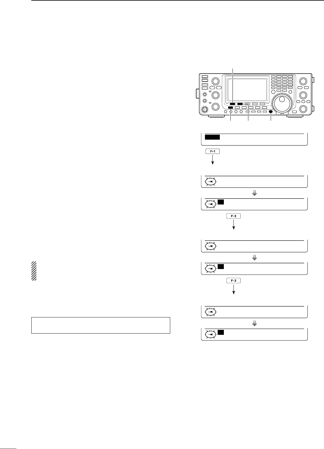
N-ESSAGEOPERATION
D48MESSAGEPROGRAMMING
The transceiver has a total of 5 message memories
to store short messages to transmit during DV mode
operation. Message of up to 20 characters can be pro-
grammed for each memory.
q
In the DV mode, p
ush [MENU] one or more times to
display the “M3” screen (Menu 3).
s)NTHE$2MODEP
ush [MENU] once or twice to select
the “D1” screen.
w
P
ush [DSET](F-5) to display the “DSET” screen.
e
P
ush [TXM](F-3) to display the “TXM” screen (Tras-
nmit message).
r Rotate [MAIN DIAL] to select the desired transmit
message channel.
s4-TO4-AND/&&ARESELECTABLE
t Push [EDT](F-1) to enter the transmit message pro-
gramming mode.
s!CURSORAPPEARSANDBLINKS
y Push [F-1] one or more times to select the desired
character type.
#HARACTERTYPE 3ELECTABLECHARACTERS
ABC A to Z
abc a to z
etc <" ’ ` ^ + – 1b
< > ( ) [ ] { } ¦ _ ¯ @
u Rotate [MAIN DIAL] to select the first character to
input.
When inputting numbers or a decimal point, push
the appropriate keypad key.
s0USH;$%,=&TODELETETHESELECTEDCHARACTERSYM-
bol or number.
s0USH;30#=&TOINPUTASPACE
s7HENALL CHARACTERSHAVEBEENprogrammed, an
error beep sounds. If you want to reprogram, push [Ω]
(F-2) or [≈](F-3) to select a character, then push [DEL]
(F-4) to delete it.
i Push [Ω](F-2) to move the cursor backward, or push
[≈](F-3) to move the cursor forward.
o Repeat steps y through i to program a message
of up to 20 characters.
!0 Push [MENU] to save the programmed message.
While [SET](F-5) is blinking, push it to set the dis-
played channel as the first appearance channel
when [TXM](F-3) is pushed in step e.
TXM
OFF
TXM
TM1:
EDT SET
ABC
TXM
TM1:HELLO
DEL SPC
[MAIN DIAL]
[MENU] [TXM]
[DSET][EDT]
Rotate [MAIN DIAL]
ABC
TXM
TM1:HELLO
DEL SPC
Character type display Cursor
[][]
[DEL][SPC] [MAIN DIAL]
Number input
Character type
selection
s0ROGRAMINGATRANSMITMESSAGE
Input a space
Delete a character
Move cursor forwards
Move cursor backwards
Character type selection
112
8
DV MODE OPERATION
8
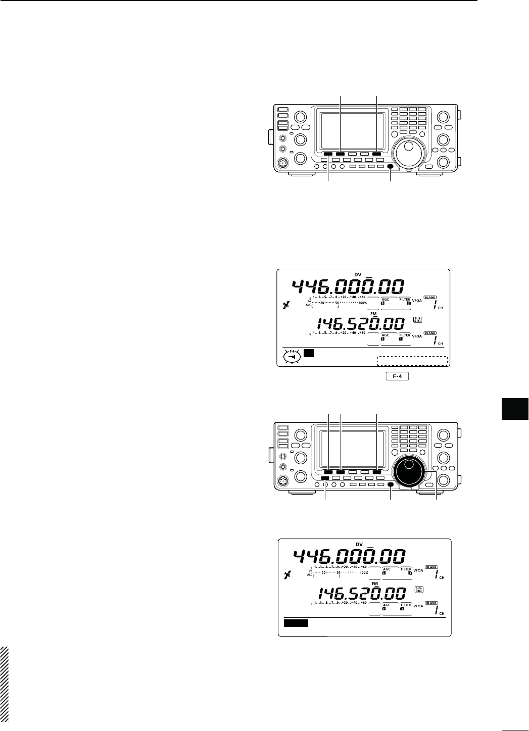
D-ESSAGE4RANSMISSION
9OUCANSELECTAMESSAGECHANNEL4-n4-TOTURN
ON the message transmission function. When a mes-
sage channel is selected, the transceiver transmits the
pre-programmed text message. The default setting is
OFF.
q Set the operating frequency, call signs and other
settings, such as those for repeater operation, as
desired.
w
In the DV mode, p
ush [MENU] one or more times to
display the “M3” screen (Menu 3).
s)NTHE$2MODEP
ush [MENU] once or twice to select
the “D1” screen.
e
P
ush [DSET](F-5) to display the “DSET” screen.
r
P
ush [TXM](F-3) to display the “TXM” screen
(Transmit message).
t Rotate [MAIN DIAL] to select the desired transmit
message channel, then push [SET](F-5).
s4-TO4-ARESELECTABLE
s7HEN/&&ISSELECTEDTHEMESSAGEISNOTTRANSMITTED
y
P
ush [MENU] to return to the “DSET” screen.
u Push [PTT] on the microphone to transmit the mes-
sage. (or push [TRANSMIT] on the transceiver)
s4HEMESSAGEISTRANSMITTEDEACHTIMEYOUPUSH;044=
(or [TRANSMIT]).
s4HEMESSAGEISAUTOMATICALLYTRANSMITTEDEVERYSEC-
onds during continuous transmission.
s4HE-!)."AND4828INDICATORLIGHTSRED
D28MESSAGEDISPLAY
q
In the DV mode, p
ush [MENU] one or more times to
display the “M3” screen (Menu 3).
s)NTHE$2MODEPUSH;-%.5=ONCEORTWICETOSELECT
the “D1” screen.
w
P
ush [CD](F-2) to display the “CD” screen (Call Re-
cord).
e Rotate [MAIN DIAL] to select the desired record
channel (RX01 to RX20).
r Push [Z](F-1) three times to select “MSG” item.
s4HERECEIVEDMESSAGEISDISPLAYED
t Push [Z](F-1) or [MENU] to return to the record
channel, selected in step e.
NOTE: Up to 20 messages can be stored, but only
one message can be stored for each call sign.
The oldest message is cleared when 21st message
is received.
EDT
TM1:
TXM
SET
[MAIN DIAL]
[MENU] [TXM]
[DSET]/[SET]
[TRANSMIT]
MAIN Band
TX/RX indicator
For your information
When a call with a message is received, the call sign
and the message scrolls across the function display.
The received call sign and/or message display func-
tions can be turned OFF in the DV SET mode, if de-
sired.
± “RX Message Disp” item (p. 119)
± “RX Call Sign Disp” item (p. 119)
[MAIN DIAL]
[MENU]
[CD][√]
CD
JG3YMK
JA3YUA
RX01
CLR COPY
CD
MSG
: REPEATER IS JP3
YHH A
Ú
After selecting the record channel,
push [Z](F-1) three times.
113
8DV MODE OPERATION
N $6AUTOMATICDETECTION
When a non-digital signal is received during DV mode
operation, the “DV” and “FM” icons simultaneously
blink. The transceiver automatically selects the FM
mode to monitor the signal, if the DV Auto Detect func-
tion is turned ON.
q
In the DV mode, p
ush [MENU] one or more times to
display the “M3” screen (Menu 3).
s)NTHE$2MODEP
ush [MENU] once or twice to select
the “D1” screen.
w
P
ush [DSET](F-5) to display the “DSET” screen.
e
P
ush [SET](F-5) to enter the DV Set mode.
r Push [Y](F-1) or [Z](F-2) to select “DV Auto De-
tect.”
t Rotate [MAIN DIAL] to turn ON the DV automatic
detect function.
s
The operating mode is set to DV
if this setting is “OFF.”
y Push [MENU] to return to the “DSET” screen.
The received FM audio may be distorted when
using this function.
[MAIN DIAL]
[MENU]
[DSET]/[SET][][]
Blink
While receiving a non-digital signal while
in the DV mode
N!UTOMATIC2EPLYFUNCTION
When a call addressed to own your call sign is re-
ceived, the Automatic Reply function automatically re-
plies with your call sign.
q
In the DV mode, p
ush [MENU] one or more times to
display the “M3” screen (Menu 3).
s)NTHE$2MODEP
ush [MENU] once or twice to select
the “D1” screen.
w
P
ush [DSET](F-5) to display the “DSET” screen.
e
P
ush [SET](F-5) to enter the DV Set mode.
r Push [Y](F-1) or [Z](F-2) to select “Auto Reply.”
t Rotate [MAIN DIAL] to turn ON the Automatic reply
function.
y Push [MENU] to return to the “DSET” screen.
NOTE:
The Automatic replay function is automati-
cally turned OFF, when
[PTT] (or [TRANSMIT]) is
pushed to transmit.
Ù
2
ÚON
SET Auto Reply
[MAIN DIAL]
[MENU]
[DSET]/[SET][][]
When the Automatic reply function is ON.
114
8
DV MODE OPERATION
8
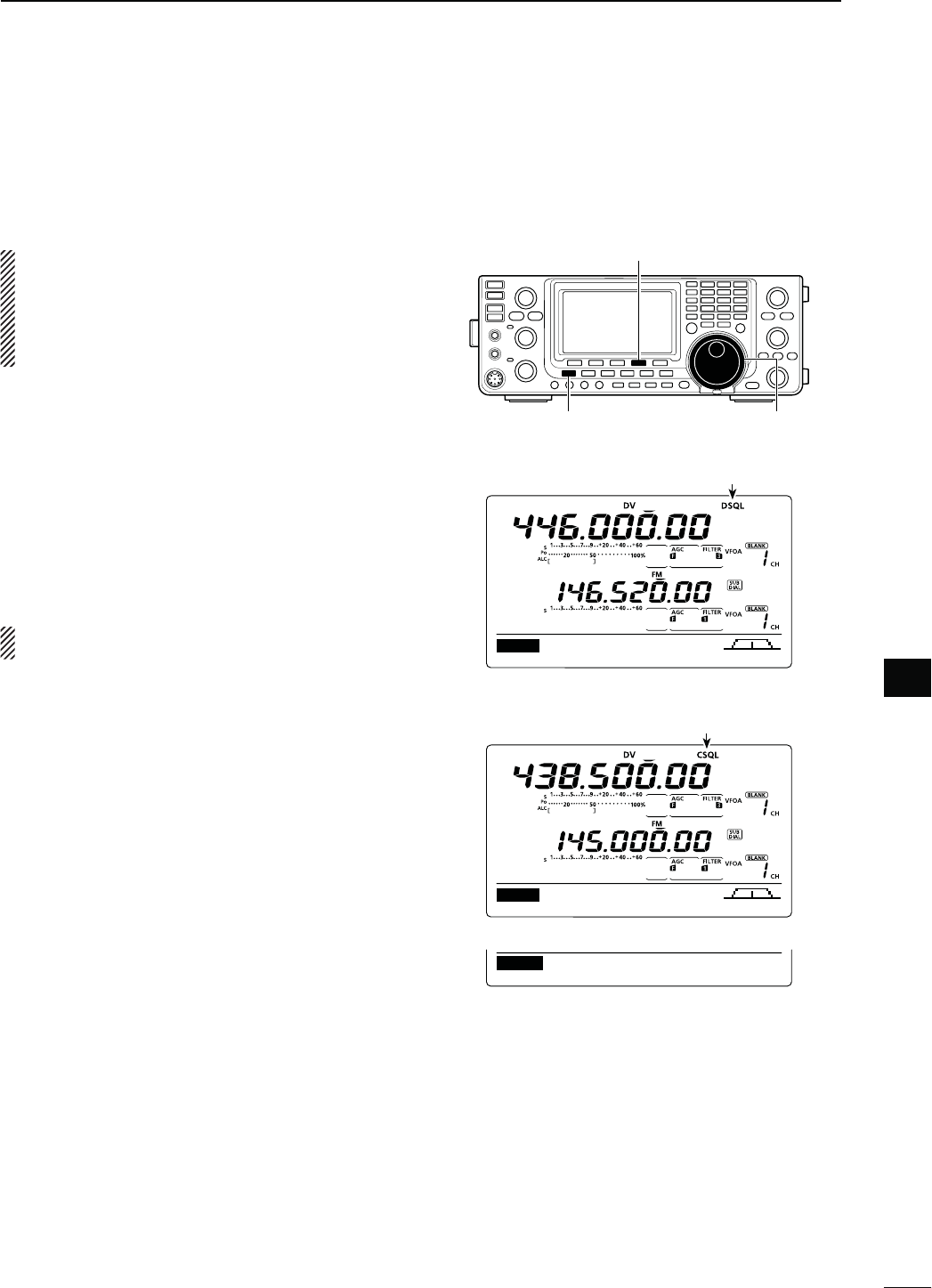
N$IGITALSQUELCHFUNCTIONS
The digital squelch opens only when receiving a sig-
nal addressed to your own call sign, or a signal that
INCLUDESAMATCHINGDIGITALCODE9OUCANSILENTLYWAIT
for calls from others.
NOTE: Use digital code squelch function when com-
municating with two or more stations, because the
digital call sign squelch function opens only when
receiving a signal addressed to your own call sign.
Thus the digital call sign squelch function can be
used when communicating with only one station.
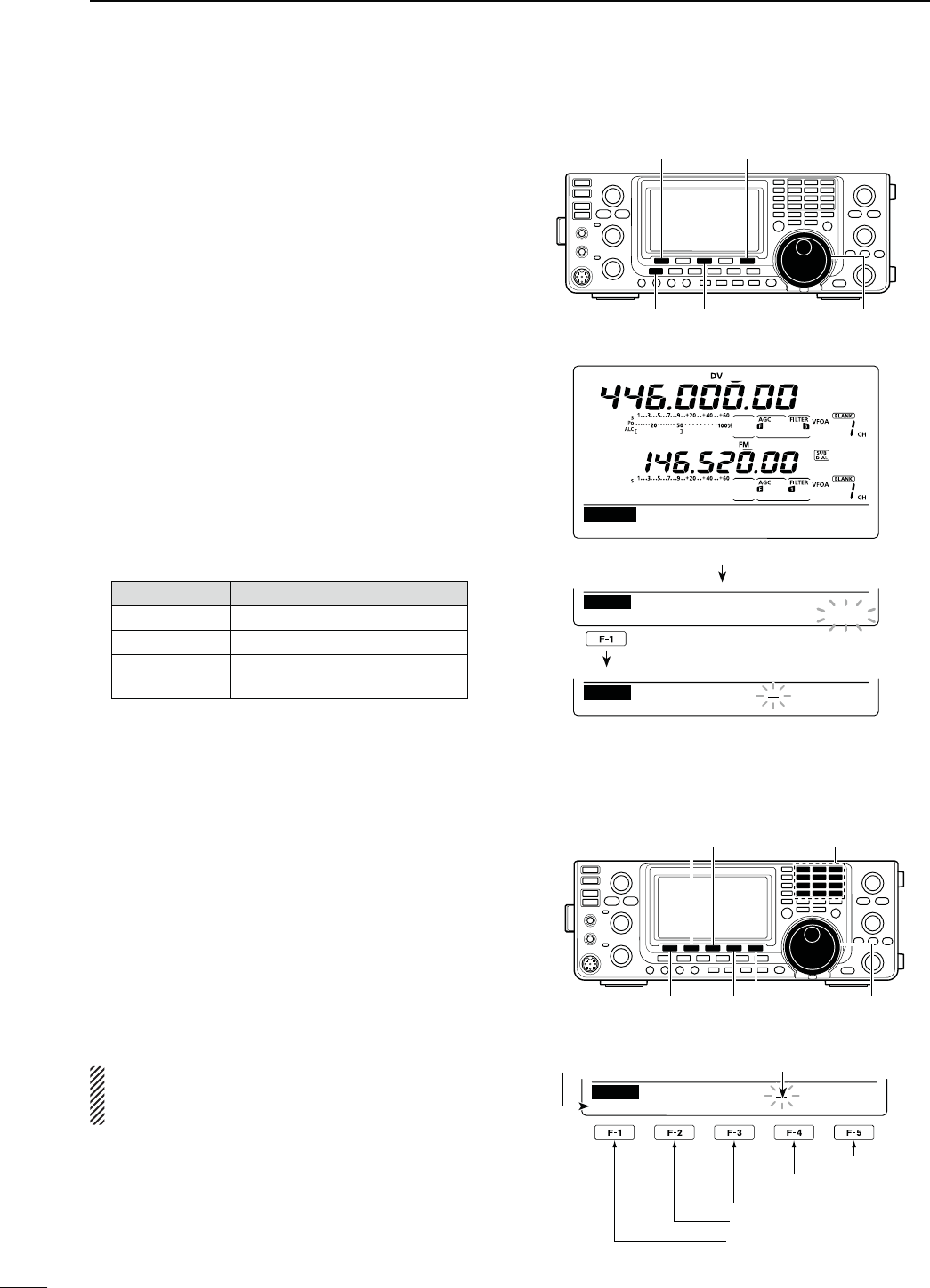
q Select the desired frequency band. (p. 35)
w
In the DV mode, p
ush [MENU] one or more times to
display the “M1” screen (Menu 1).
s)NTHE$2MODEP
ush [MENU] once or twice to select
the “D2” screen.
s4HESETTINGCANBERESPECTIVELYMADEINTHE$6MODE
and the DR mode.
e Push [DSQ](F-4) one or more times to turn ON the
digital call sign squelch or digital code squelch.
sh$31,vAPPEARSWHENTHEDIGITALCALLSIGNSQUELCHIS
ON.
sh#31,vAPPEARSWHENTHEDIGITALCODESQUELCHIS/.
When digital call sign squelch is turned ON in step
e, skip steps r and t, and go to step y.
r When digital code squelch is turned ON in step e,
hold down [DSQ](F-4) for 1 second to display the
“DSQ” screen. And rotate [MAIN DIAL] to select the
desired code between 00 and 99.
s(OLDDOWN;&=FORSECONDTORESETTOTHEDEFAULTSET-
ting, if desired.
t
P
ush [MENU] to return to the “M1” screen (Menu
1).
s)NTHE$2MODERETURNTO
the “D2” screen.
y When the received signal includes a matching call
sign/code, the squelch opens and the signal can be
heard.
s7HEN THE RECEIVED SIGNALS CALL SIGNCODE DOES NOT
match, digital call sign/digital code squelch does not
OPENHOWEVERTHE3METERSHOWSSIGNALSTRENGTH
M1
DUPAGC AFC DSQ SCP
M1
DUPAGC AFC DSQ SCP
[MAIN DIAL]
[MENU]
[DSQ]
Appears
00
DSQ Digital Code
“DSQ” screen (Digital code setting)
Appears
115
8DV MODE OPERATION
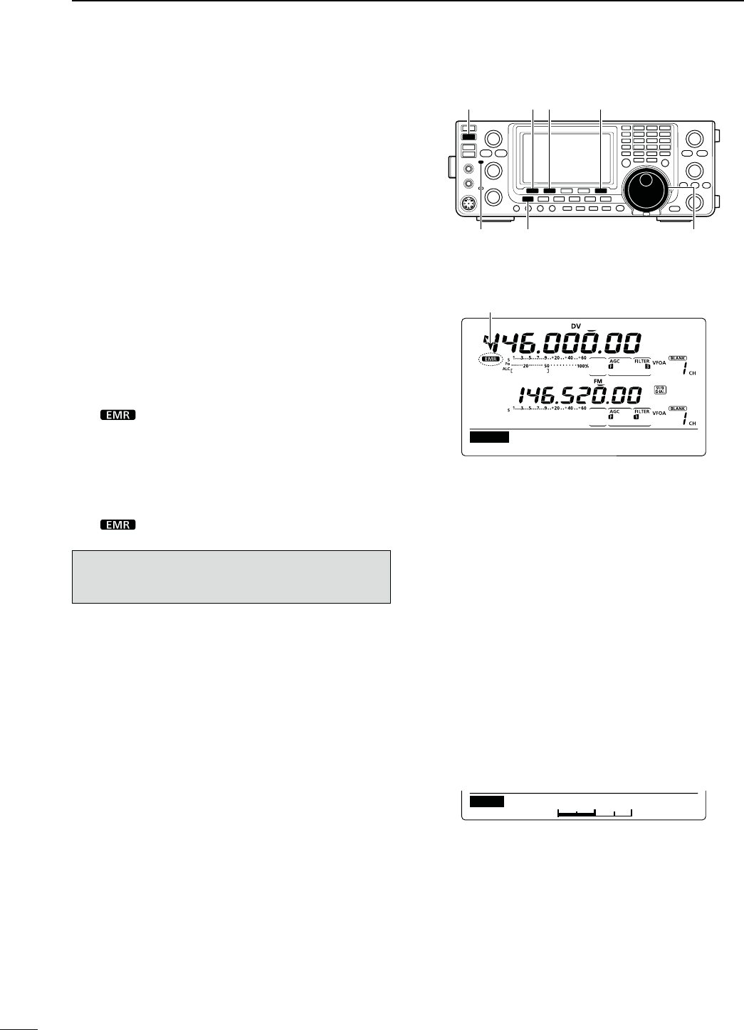
N%-2COMMUNICATION
The EMR (Enhanced Monitor Receive) communication
mode can be used in only the DV mode. In the EMR
mode, no call sign setting is necessary. When an EMR
mode signal is received, the audio (voice) will be heard
at the specified level, even if the volume setting level
is set to the minimum level, or digital call sign/digital
code squelch is in use.
q Select the desired frequency band. (p. 35)
w Set the desired frequency. (p. 37)
e
In the DV mode, p
ush [MENU] one or more times to
display the “M3” screen (Menu 3).
s)NTHE$2MODEP
ush [MENU] once or twice to select
the “D1” screen.
r
P
ush [DSET](F-5) to display the “DSET” screen.
t
P
ush [SET](F-5) to enter the DV Set mode.
y Push [Y](F-1) or [Z](F-2) to select “EMR.”
u Rotate [MAIN DIAL] to turn ON the EMR mode.
s“ ” appears.
i Push [MENU] to return to the “DSET” screen.
o Push [PTT] on the microphone to transmit. (or
[TRANSMIT] on the transceiver)
s4HE-!)."AND4828INDICATORLIGHTSRED
!0 Release [PTT] to receive. (or push [TRANSMIT]
again)
s“ ” blinks when receiving an EMR signal.
NOTE: The EMR communication function is auto-
matically turned OFF when the transceiver is turned
OFF.
19
ON
SET
EMR
Ù
20
Ú50%
SET EMR AF Level
[TRANSMIT]
MAIN Band
TX/RX indicator
[MAIN DIAL]
[MENU]
[DSET]/[SET][][]
When the EMR communication mode is ON.
DEFAULT
Appears
D!DJUSTINGTHE%-2!&LEVEL
The audio output level when an EMR signal is received
is adjustable.
When an EMR signal is received, the audio will be
heard at the preset level, or the [AF] control level,
whichever is higher.
q
In the DV mode, p
ush [MENU] one or more times to
display the “M3” screen (Menu 3).
s)NTHE$2MODEP
ush [MENU] once or twice to select
the “D1” screen.
w
P
ush [DSET](F-5) to display the “DSET” screen.
e
P
ush [SET](F-5) to enter the DV Set mode.
r Push [Y](F-1) or [Z](F-2) to select “EMR AF
Level.”
t Rotate [MAIN DIAL] to adjust the EMR audio out-
PUTLEVELBETWEENMINIMUMANDMAXI-
mum).
s(OLDDOWN[F-3] for 1 second to reset to the default set-
ting, if desired.
y Push [MENU] to return to the “DSET” screen.
116
8
DV MODE OPERATION
8
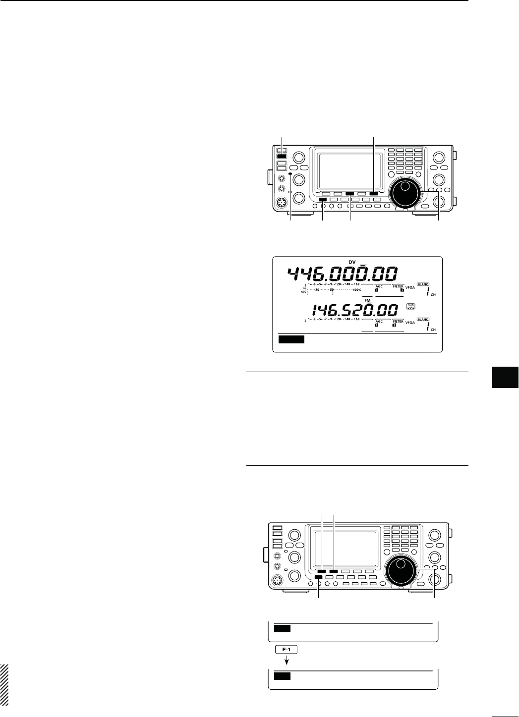
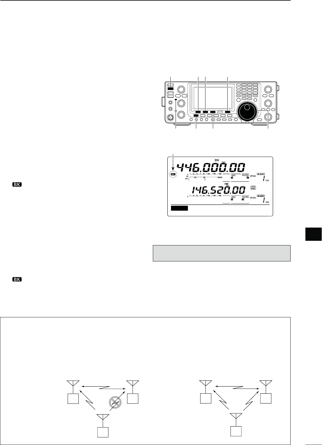
N"REAKINCOMMUNICATION
The break-in function allows you to break into a con-
versation, where the two other stations are communi-
cating with call sign squelch enabled.
q While receiving another station’s communication
in
the DV mode, p
ush [MENU] one or more times to
display the “M3” screen (Menu 3).
s)NTHE$2MODEP
ush [MENU] once or twice to select
the “D1” screen.
w Hold down [R>CS](F-3) for 1 second to set the
other station’s call sign.
s7HENACALLSIGNHASNOTBEENRECEIVEDCORRECTLYERROR
beeps sound, and no call sign is set. Try to capture the
call sign of the signal again, or enter it manually.
e
P
ush [DSET](F-5) to display the “DSET” screen.
r
P
ush [SET](F-5) to enter the DV Set mode.
t Push [Y](F-1) or [Z](F-2) to select “BK.”
y Rotate [MAIN DIAL] to turn ON the break-in func-
tion.
s“ ” appears.
u Push [MENU] to return to the “DSET” screen.
i When both stations are in standby, push [PTT] on
the microphone to transmit. (or push [TRANSMIT]
on the transceiver)
s4HEPROGRAMMEDCALLSIGNSTATIONRECEIVESTHEBREAKIN
call as well as your call sign.
s4HE-!)."AND4828INDICATORLIGHTSRED
o Release [PTT] to receive. (or push [TRANSMIT]
again)
Wait for a reply call from the station who received
the break-in call.
!0 After receiving the reply call, communicate nor-
mally.
s“ ” blinks when receiving a break-in call.
!1 To cancel the break-in function, turn OFF the Break-
in function in the DV Set mode as shown in steps r
through y.
18
ON
SET
BK
[TRANSMIT]
MAIN Band
TX/RX indicator
[MAIN DIAL]
[MENU] [R>CS]
[DSET]/[SET][][]
When the Break in function is ON.
Appears
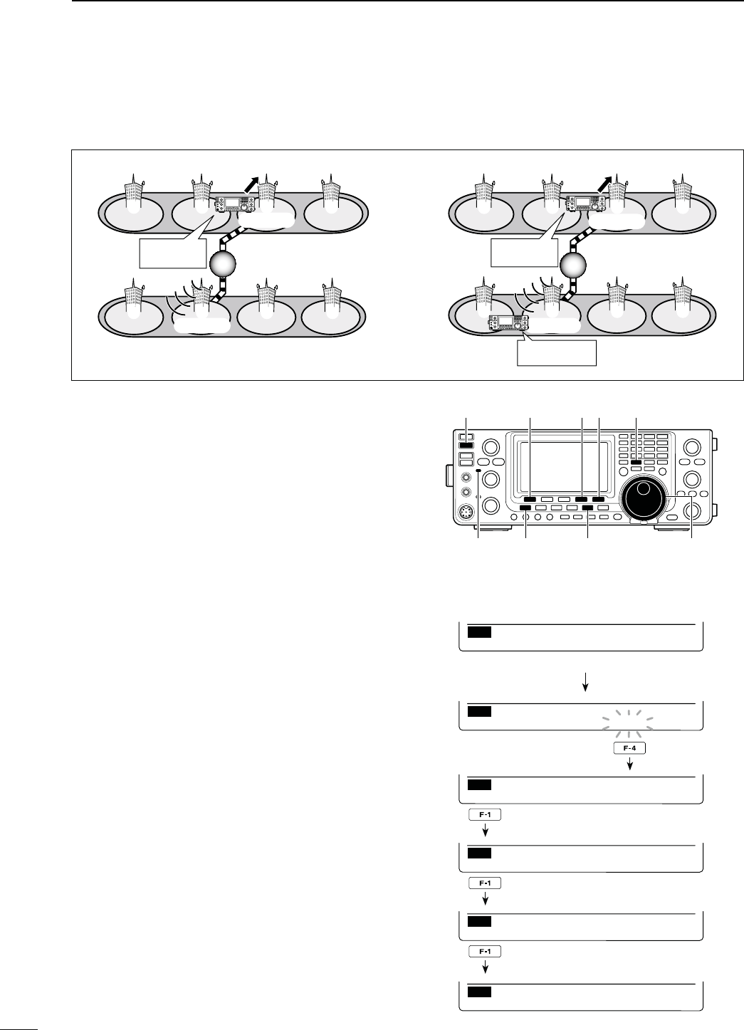
(OWTOUSEBREAKIN
While using digital call sign squelch, the squelch never opens (no audio sounds) even if a call is received, unless
YOUROWNCALLSIGNh-9vISSPECIlEDP
However, when a call including the “BK ON” signal (break-in call) is received, the squelch will open and audio
sounds even if the call is specified for another station.
Station A Station B
Station C
Station A Station B
Station C
Station A and B
are communicating
using the digital
call sign squelch.
Station A and B
are communicating
using the digital
call sign squelch.
Station B never hears that
Station C is calling Station A.
Station B also hears that
Station C is calling Station A.
NOTE: The break-in function is automatically turned
OFF when transceiver is turned OFF.
117
8DV MODE OPERATION
In addition to digital voice communication, low-speed
data communication can be made.
Use the optional OPC-1529R DATA COMMUNICATION
CABLE with a third-party serial data communication
software.
s!53"PORTCANALSOBEUSEDFORTHELOWSPEEDDATACOM-
munication, depending on the “USB2/DATA1 Func (^3)”
item setting in the Set mode. (p. 164)
NOTE: First, turn OFF the “GPS TX Mode” item in
the GPS Set mode to send the low-speed data. (p.
134)
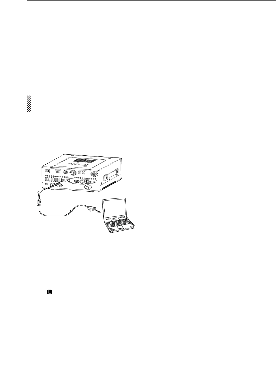
D#ONNECTION
Connect the transceiver to your PC using the optional
OPC-1529R cable, as illustrated below.
OPC-1529R
(optional)
To the [DATA1] jack
IC-9100 (Rear panel)
PC
To RS-232C
port
D,OWSPEEDDATACOMMUNICATION
APPLICATIONSETTING
Configure the serial data communication software as
follows.
s0ORT 4HE#/-PORTNUMBERWHICHISUSED
by the IC-9100.*1
s"AUDRATE BPS2
s$ATA BIT
s0ARITY .ONE
s3TOP BIT
s&LOWCONTROL8ON8OFF
*1 Depending on the PC environment, the COM port number
used by the IC-9100 may be higher than 5. In such case,
use the application which can set to higher than 5.
*2 Set the baud rate in the “DVdat/GPS Out Baud” item of the
Set mode. (p. 168)
D,OWSPEEDDATACOMMUNICATION
OPERATION
q Set the desired call signs as described in ‘Call sign
setting.’ (p. 93)
w Follow the instructions of the data communication
application software.
e Push [PTT] on the microphone to transmit the data
and an audio signal. (or push [TRANSMIT] on the
transceiver)
s4HE-!)."AND4828INDICATORLIGHTSRED
sThe input data from the [DATA1] jack are automatically
transmitted when “AUTO” is selected in the “DV Data
TX” item of the DV Set mode. (p. 118)
N 0ACKETLOSSINDICATION
While operating voice communication or low-speed
data communication through the internet, some
packets may be lost due to network error (poor data
throughput performance). In such a case, the IC-9100
displays “ ” on the display to indicate Packet Loss has
occurred.
N,OWSPEEDDATACOMMUNICATION
118
8
DV MODE OPERATION
8
N$63ETMODEDESCRIPTION
The DV Set mode is used for programming infrequently
changed values or functions in the DV mode.
D DV 3ETMODESETTINGS
q
In the DV mode, p
ush [MENU] one or more times to
display the “M3” screen (Menu 3).
s)NTHE$2MODEP
ush [MENU] once or twice to select
the “D1” screen.
w
P
ush [DSET](F-5) to display the “DSET” screen.
e
P
ush [SET](F-5) to enter the DV Set mode.
r Push [Y](F-1) or [Z](F-2) to select the desired
item.
t Rotate [MAIN DIAL] to select the desired option.
s(OLDDOWN[F-3] for 1 second to reset to the default set-
ting, if desired.
y Push [MENU] to save, and return to the “DSET”
screen.
3TANDBY"EEP1. $EFAULT/.
Turn the Standby beep function ON or OFF.
This function sounds a beep when the other station
stops transmitting.
s/&& 4URNS/&&THEFUNCTION
s/. 4URNS/.THEFUNCTIONTOSOUNDABEEP
s/. 4URNS/.THEFUNCTIONTOSOUNDABEEP
If the call was sent to your call sign, the beep
has a higher pitch.
!UTO2EPLY2. $EFAULT/&&
Turn the automatic reply function ON or OFF.
This function automatically replies to a call addressed
to your own call sign, even if you are away from the
transceiver.
This function is automatically turned OFF after you
push [PTT] (microphone) or [TRANSMIT].
s/&& 4URNS/&&THEFUNCTION
s/. 4HETRANSCEIVERAUTOMATICALLYREPLIESTOTHE
call with your own call sign.
$6$ATA483. $EFAULT044
For low-speed data communication, select whether to
transmit the input data manually or automatically.
s044 0USH;044=MICROPHONEOR;42!.3-)4=TO
manually transmit the input data.
s!UTO 7HENDATAISINPUTFROMA0#THROUGHTHE
[DATA1] jack, the transceiver automatically
transmits it.
$IGITAL-ONITOR4. $EFAULT!UTO
Select the RX monitoring mode by holding down [XFC]
while in the DV mode.
s!UTO
Monitors in the DV mode or FM mode, de-
pending on the received signal.
s$IGITAL -ONITORSINTHE$6MODE
s!NALOG-ONITORSINTHE&-MODE
$IGITAL2043ET5. $EFAULT/.
Turn the digital repeater setting function ON or OFF.
When accessing a repeater that has a call sign dif-
ferent than the transceiver’s “R1” setting, this function
reads the repeater’s downlink signal and automatically
sets the correct repeater call sign into “R1.”
s/&& 4URNS/&&THEFUNCTION
s/. !UTOMATICALLYSETSTHEREPEATERCALLSIGN
28#ALL3IGN7RITE6. $EFAULT/&&
Turn the RX call sign automatic write function ON or
OFF.
When receiving a call addressed to your own call sign,
this function automatically sets the call sign of the call-
ing station into “UR.”
While in the DR mode, this function is disabled.
s/&& 4URNS/&&THEFUNCTION
s!UTO !UTOMATICALLYSETSTHECALLSIGNOFTHECALLING
station into “UR.”
1
ON–1
Standby Beep
SET
Select the item Reset to the default
setting
Displays the DV Set mode
item name and number Displays the option
[MAIN DIAL]
[MENU]
[DSET]/[SET][][]

119
8DV MODE OPERATION
282047RITE7. $EFAULT/&&
Turn the repeater call sign automatic write function ON
or OFF.
When you receive a call addressed to your own call
sign through a repeater, this function automatically
sets the repeater call signs included in the signal, into
your current “R1” and “R2.”
While in the DR mode, this function is disabled.
OFF : Turns OFF the function.
Auto : Automatically sets the call sign of the used re-
peater into your “R1” and “R2.”
DV Auto Detect 8. $EFAULT/&&
Turn the DV mode automatic detect function ON or
OFF.
When receiving other than a DV mode signal, dur-
ing DV mode operation, this function automatically
switches to the FM mode.
s/&& Turns OFF the function. The operating mode
is fixed to the DV mode.
s/. Automatically selects the FM mode for tem-
porary operation.
The received FM audio may be distorted when re-
ceiving an FM signal with this function.
%DIT2ECORD9. $EFAULT!UTO
Select an option for the call sign edit record function.
When a call sign in the memory is edited, this function
saves the new call sign in a different memory than the
original one.
sOFF :
Turns OFF the function. The previously set call
sign is overwritten with the edited call sign.
sSelect : The edited call sign is programmed into the
selected call sign memory.
sAuto : The edited call sign is automatically pro-
grammed into a blank memory.
'ATEWAY!UTO3ET10. $EFAULT!UTO
Turn the gateway automatic set function ON or OFF for
calling an individual station in the DR mode.
This function enables the transceiver to automatically
set the pre-programmed gateway repeater in “R2.”
s/&& %VENSELECTINGANINDIVIDUALSTATIONIN“UR,”
the previously used repeater call sign re-
mains in R2.
s!UTO !FTERSELECTINGANINDIVIDUALSTATIONIN“UR,”
the pre-programmed gateway repeater is au-
tomatically set in R2.
282ECORD20411. $EFAULT!,,
The transceiver can record data of up to 20 individual
calls.
Select whether to record all calls or only the latest call
whose called station did not reply, or whose Link re-
peater was not found.
sALL : Records all calls.
sLatest Only : Records only the latest call.
28#ALL3IGN$ISP12. $EFAULT!UTO
When a call is received, the call sign of the calling sta-
tion can be automatically displayed.
sOFF : Turns OFF the function.
sAuto : Automatically displays the call sign of the
calling station.
48#ALL3IGN$ISP13. $EFAULT52
Select whether or not to display the programmed call
SIGN-9OR52ATTHEBEGINNINGOFYOURTRANSMIS-
sion.
sOFF : Turns OFF the function.
sUR : Displays the call sign of the station you
called.
s-9 : Displays your own call sign.
28-ESSAGE$ISP14. $EFAULT!UTO
Select whether or not to display and scroll a received
message.
sOFF : Does not display the message. To check the
message, push [CD] (F-2) in M3, and then
select MSG.
sAuto : Automatically displays and scrolls the mes-
sage.
3CROLL15. $EFAULT&AST
Select the scrolling speed of a message or call sign.
sSlow : Sets the scrolling speed to “Slow.”
sFast : Sets the scrolling speed to “Fast.”
$2#ALL3IGN0OPUP16. $EFAULT/.
Select whether or not to display a selected station or
repeater call sign when the DR mode is selected, or
when you switch the “UR,” “R1” and “R2” display while
in the DR mode.
s/&& !CALLSIGNISNOTDISPLAYED
s/. !CALLSIGNISDISPLAYED
N DV Set mode description (Continued)

120
8
DV MODE OPERATION
8
/PENING#ALL3IGN17. $EFAULT/&&
3ELECTWHETHERORNOTTODISPLAY-9CALLSIGNONTHE
LCD when the transceiver is turned ON.
sOFF : Turns OFF the function.
s/. $ISPLAYS-9CALLSIGNATPOWER/.
"+ 18. $EFAULT/&&
The break-in function allows you to break into a con-
versation where two other stations are communicating
with call sign squelch enabled.
See page 116 for details.
s/&& 4HEBREAKINFUNCTIONISSETTO/&&
s/. 4HEBREAKINFUNCTIONISSETTO/.
s“” appears on the display.
NOTE: The break-in function is automatically turned
OFF when the transceiver is turned OFF.
EMR 19. $EFAULT/&&
The EMR communication mode can be used for digital
mode operation. In the EMR mode, no call sign setting
is necessary. When an EMR mode signal is received,
the audio (voice) will be heard at the specified level
even if the volume setting level is set to minimum level,
or digital call sign/digital code squelch is in use.
See page 115 for details.
s/&& 4HE%-2FUNCTIONISSETTO/&&
s/. 4HE%-2FUNCTIONISSETTO/.
s“” appears on the display.
NOTE: The EMR communication function is auto-
matically turned OFF when the transceiver is turned
OFF.
%-2!&,EVEL20. $EFAULT
%NTERANUMBERBETWEENMINIMUMAND
(maximum) to set the audio output level when an EMR
signal is received.
When an EMR signal is received, the audio will be
heard at the programmed level, or the [AF] control
level, whichever is higher.
9
121
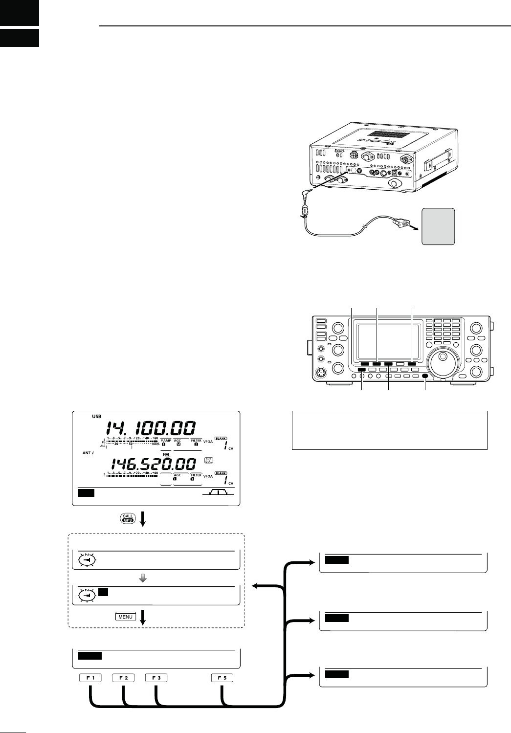
GPS/GPS-A OPERATION
N'03OPERATION
9OUCANDISPLAYYOUROWN'03DATAINALLOPERATING
MODES9OUCANALSOTRANSMIT'03DATAWHENINTHE
DV mode. To receive GPS data, connect a third-party
GPS receiver that has an RS-232C output and NMEA
data format. Third-party GPS receivers connect to the
[DATA1] jack of the transceiver.
In addition, GPS messages can also be transmitted in
the GPS mode.
s4OCONNECTTHE'03RECEIVER
GPS
receiver
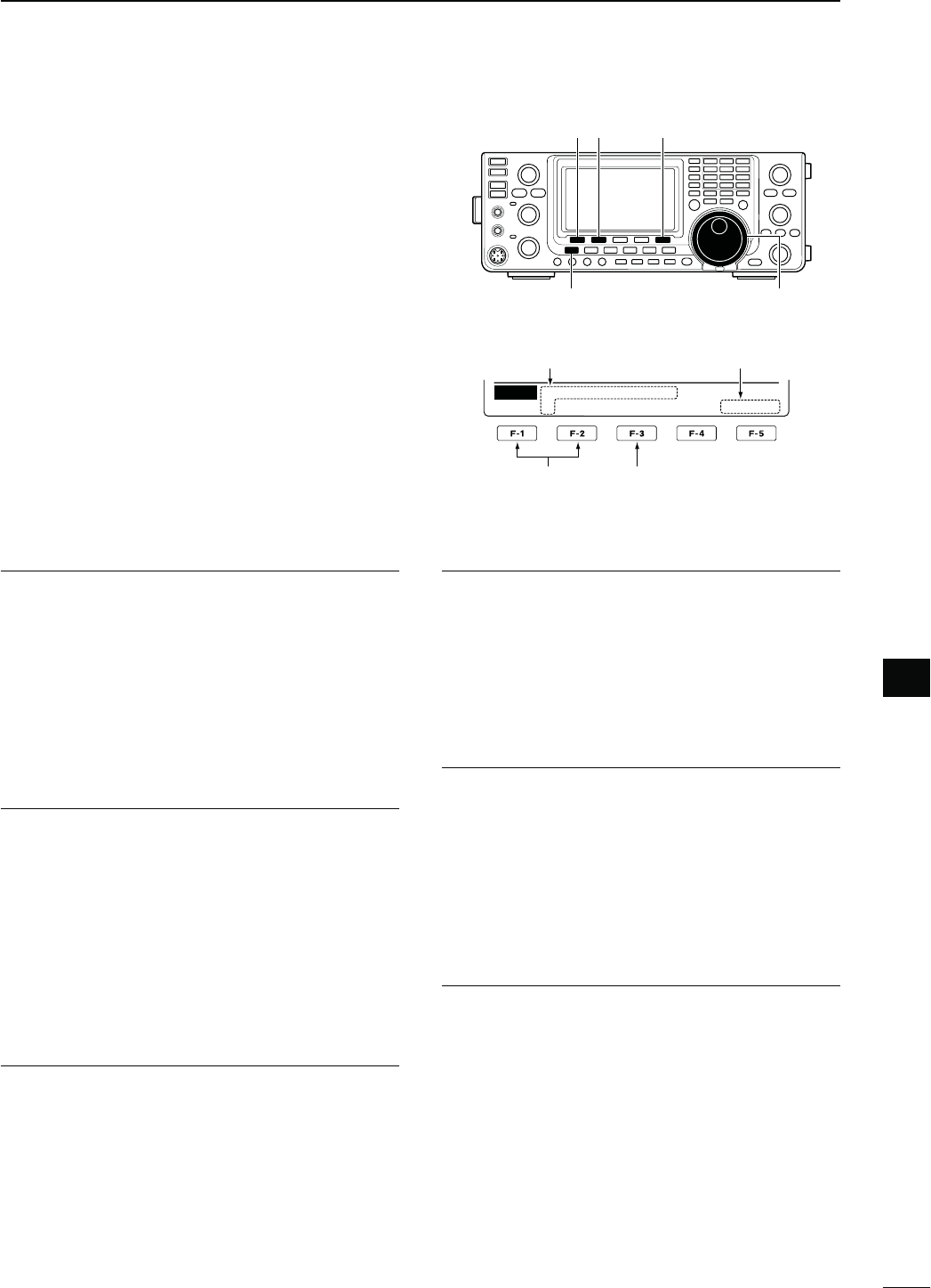
D'03SCREENCONSTRUCTION
q Hold down [CALL/GPS] for 1 second to display the
“GPS” screen.
w Push [POS](F-1), [GPM](F-2), [MSG](F-3) or [SET]
(F-5) to select the desired menu.
See the diagram below.
s0USH;-%.5=TORETURNTOTHEPREVIOUSDISPLAY
AGC DUP COMP TBW SCP
M1
1
4800
SET
GPS Receiver Baud
GPMPOS MSG SET
GPS
GL WR
MY Position
M
35˚45.00’N ELE:−−−−ft
135˚36.00’E 12:00:00
ALM
GPM
RX
RXMTXM
MSG
GPS Message
s'03SCREEN
s0OSITIONSCREEN (p. 123) s'03-EMORYSCREEN (p. 127)
s'03-ESSAGESCREEN (p. 125)
[F-1]
[F-2]
[F-3]
[POS]
[MENU] [MSG] [CALL/GPS]
[GPM] [SET]
The screen you want to appear first can be se-
lected between GPS and Position in the “GPS
1st Menu” item of the Set mode. (p. 165)
Hold down
s'033ETMODESCREEN (p. 132)
Push
Approximately 2 seconds
[F-5]
to the RS-232C port
( null modem adapter
is required)
OPC-1529R
(optional)
4RANSCEIVER
(Rear panel)
To the [DATA1] jack
122
9
GPS/GPS-A OPERATION
9
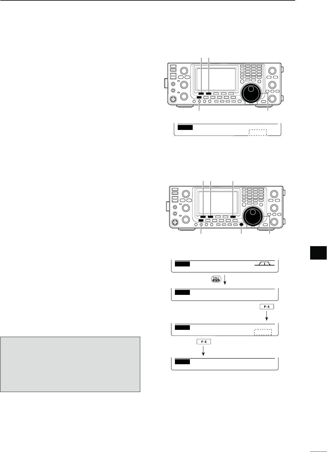
D3ENTENCEFORMATTERSETTING
q Hold down [CALL/GPS] for 1 second to display the
“GPS” screen.
w Push [SET](F-5) to enter the GPS Set mode.
e Push [Y](F-1) or [Z](F-2) to select “GPS TX
Mode.”
r Rotate [MAIN DIAL] to select “GPS.”
s)Fh$ISABLEvORh'03!vISSELECTEDTHESENTENCEFORMAT-
ter items as described in step t will not appear.
t Push [Y](F-1) or [Z](F-2) to select the desired GPS
sentence.
s!TOTALOFSENTENCES2-#''!',,'3!64'AND
GSV are selectable.
y Rotate [MAIN DIAL] to turn the sentence ON or
OFF.
s(OLDDOWN;&=FORSECONDTORESETTOTHEDEFAULTSET-
ting, if desired.
u Repeat steps t and y to select another GPS sen-
tence.
s5PTOFOUR'03SENTENCESCANBESELECTED
i Push [MENU] to save, and return to the “GPS”
screen.
NOTE:
Set the GSV sentence to OFF when sending the
GPS message to conventional digital transceivers
(IC-2820H, IC-E2820, ID-800H, IC-91AD, IC-E91,
IC-V82, IC-U82, IC-2200H, ID-1).
The GSV sentence is incompatible with them. Those
transceivers will not display GPS messages properly
if a GSV sentence is sent from the IC-9100.
GPMPOS MSG SET
GPS
Push
[SET]
[CALL/GPS] [MAIN DIAL][MENU]
[][]
Ù
12
ÚGPS
SET GPS TX Mode
Ù
13
ÚON
SET GPS Sentence (RMC)
Push
Select
DUPAGC AFC TON SCP
M1
Hold down
When RMC sentence usage is set to ON.
D'03DATACOMMUNICATION
The transceiver transmits GPS data or low-speed data
to the PC through the [DATA1] jack, depending on the
Set mode setting. (p. 168)
q Hold down [MENU] for 1 second to enter the Set
mode.
w Push [Y](F-1) or [Z](F-2) to select “USB2/DATA1
Func.” (64)
e Rotate [MAIN DIAL] to select “GPS” as the func-
tion of the [DATA1] jack to be used for position data
input.
r Push [MENU] to save, and exit the Set mode.
[MAIN DIAL][MENU]
[][]
Ù
64
Ú––––– ⁄ GPS ]
SET USB2⁄DATA1 Func
GPS (default)
123
9GPS/GPS-A OPERATION
N GPS operation (Continued)
D0OSITIONDISPLAY
q Hold down [CALL/GPS] for 1 second to display the
“GPS” screen.
w Push [POS](F-1) to display the position data. Then
push [F-2] one or more times to display your current
position, received position or GPS memory alarm
position information.
s7HILETHEPOSITIONDATAISDISPLAYEDPUSH;&=TOSELECT
North or South as the top of the compass.
s-90OSITION $ISPLAYSYOUROWNLATITUDELONGI-
tude, direction*, elevation* and the
time*.
* These items do not appear when
h-ANUALvISSELECTEDASTHEh-90O-
sition” item option in the GPS Set
mode. (p. 132)
s280OSITION $ISPLAYSTHECALLERSOTHERSTATION
latitude, longitude, call sign, direc-
tion and distance from your posi-
tion.
s'0-0OSITION$ISPLAYSTHE'03-EMORYCHAN-
nel’s latitude, longitude, direction
and distance from your position,
if the GPS Alarm function is set to
the channel.
s)FTHE'03!LARMFUNCTIONISSETTOALL
channels or a bank, “–” is displayed
instead of the position information.
e Push [MENU] to return to the “GPS” screen.
NOTE: Depending on the GPS signals, your posi-
tion/elevation may change even though you are sta-
tionary.
These sample indications assume that “Position For-
mat” is selected as “ddd°mm.mm,” and “Units” is se-
lected as “feet/mile.” (p. 132)
“TIME” data may not be displayed, depending on the
connected GPS receiver.
[F-2] [CALL/GPS][MENU]
[POS]
Ú
GL
Ú
GPM Position
G
35˚45.00’N
135˚36.00’E DST:1051
ml
GL WR
GL WR
MY Position
GPMPOS MSG SET
GPS
M
20˚35.00’N ELE: 16ft
134˚26.00’E 12:00:00
Ú
RX Position
R
35˚45.00’N JA3YMK
135˚36.00’E DST:1051
ml
Push
Push
Push
s-YPOSITION
s2ECEIVEDPOSITION
s'03-EMORYALARMPOSITION
Approximately 2 seconds
Approximately 2 seconds
Approximately 2 seconds
124
9
GPS/GPS-A OPERATION
9
D'03AUTOMATICTRANSMISSION
In the DV mode, this function automatically transmits
the GPS receiver’s current position data, at a selected
interval.
When a GPS message is programmed, the transceiver
transmits it along with the position data. See page 125
for the GPS message programming.
q Hold down [CALL/GPS] for 1 second to display the
“GPS” screen.
w Push [SET](F-5) to enter the GPS Set mode.
e Push [Y](F-1) or [Z](F-2) to select “GPS Auto TX.”
r Rotate [MAIN DIAL] to select the desired position
DATATRANSMITTINGINTERVALTOORSECONDS
3, 5, 10 or 30 minutes, or OFF.
* If four GPS sentences are selected in GPS Set mode on
page 122, “5 sec.” cannot be selected.
s4HE'03MESSAGEISALSOTRANSMITTEDIFPROGRAMMED
t Push [MENU] to save, and return to the “GPS”
screen.
NOTE:
s9OUROWNCALLSIGNMUSTBEENTEREDTOACTIVATETHE
GPS automatic transmission. (p. 93)
sUse GPS automatic transmission in only the sim-
plex mode.
s GPS automatic transmission through a repeater
may interfere with other communications.
[SET]
[CALL/GPS] [MAIN DIAL][MENU]
[][]
OFF (default)
Ù
11
ÚOFF
SET GPS Auto TX
q Hold down [CALL/GPS] for 1 second to display the
“GPS” screen.
w Push [POS](F-1), then push [F-2] once or twice to
display your own or the caller’s (other station) posi-
tion information.
s9OU CANNOT SAVE THE DATA ON THE h'0- 0OSITIONv
screen.
e Hold down [F-5] for 1 second to save the position
data to GPS memory (G00).
s4HE-EMORYCHANNELNUMBERADVANCESAUTOMATICALLYIF
the next Memory channel already contains information.
s'03-EMORYCHANNELAREAVAILABLE
D$ISPLAYTHE'RID,OCATORINFORMATION
The Grid Locator expresses the latitude and longitude
position data in a short string of characters. The IC-
9100 can display it on the LCD.
q Hold down [CALL/GPS] for 1 second to display the
“GPS” screen.
w Push [POS](F-1), then push [F-2] one or more times
to display the position information.
e While holding down [F-4], the grid locator informa-
tion is displayed.
M
35˚45.00’N
135˚36.00’E GL:PM75TS
Hold down
[POS] [CALL/GPS]
[F-5][F-2]
D3AVINGYOUROWNORRECEIVEDPOSITIONDATA
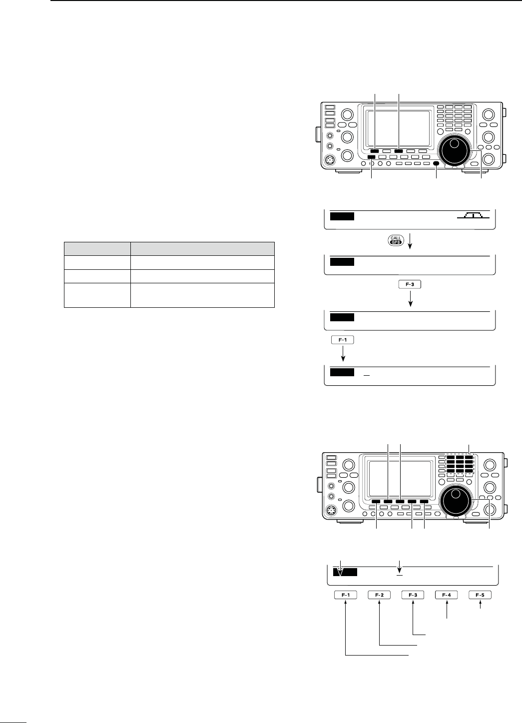
125
9GPS/GPS-A OPERATION
N GPS operation (Continued)
D'03MESSAGEPROGRAMMING
Enter a GPS message of up to 20 characters to be
transmitted with the position data.
q Hold down [CALL/GPS] for 1 second to display the
“GPS” screen.
w Push [MSG](F-3) to display the “MSG” screen (GPS
Message).
e Push [TXM](F-1) to display the “TXM” screen (TX
Message Edit).
s!CURSORAPPEARSANDBLINKS
r Push [F-1] one or more times to select the desired
character type.
#HARACTERTYPE 3ELECTABLECHARACTERS
ABC A to Z
abc a to z
etc <" ’ ` ^ + – 1b
( ) [ ] { } ¦ _ ¯ @
t Rotate [MAIN DIAL] to select the first character or
symbol to input.
When inputting numbers or a decimal point, push
the appropriate keypad key.
s0USH;$%,=&TODELETETHESELECTEDCHARACTERSYM-
bol or number.
s0USH;30#=&TOINPUTASPACE
s7HENALL CHARACTERSHAVEBEENprogrammed, an
error beep sounds. If you want to reprogram, push [Ω]
(F-2) or [≈](F-3) to select a character, then push [DEL]
(F-4) to delete it.
y Push [Ω](F-2) to move the cursor backward, or push
[≈](F-3) to move the cursor forward.
u Repeat steps r to y to program a message of up
to 20 characters.
i Push [MENU] to save the message, and return to
the “MSG” screen (GPS Message).
o Push [MENU] again to return to the “GPS” screen.
[MSG]
[CALL/GPS] [MAIN DIAL][MENU]
[TXM]
GPMPOS MSG SET
GPS
Push
ABC
DEL SPC
TXM
DUPAGC AFC TON SCP
M1
Hold down
[][]
[F-1] [DEL][SPC] [MAIN DIAL]
Keypad
s4OPROGRAMAMESSAGE
ABC
DEL SPC
XM
I ’ m
Character type Cursor
Input a space
Delete a character
Move cursor forward
Move cursor backward
Select the character type
RXMTXM
MSG
GPS Message
Push
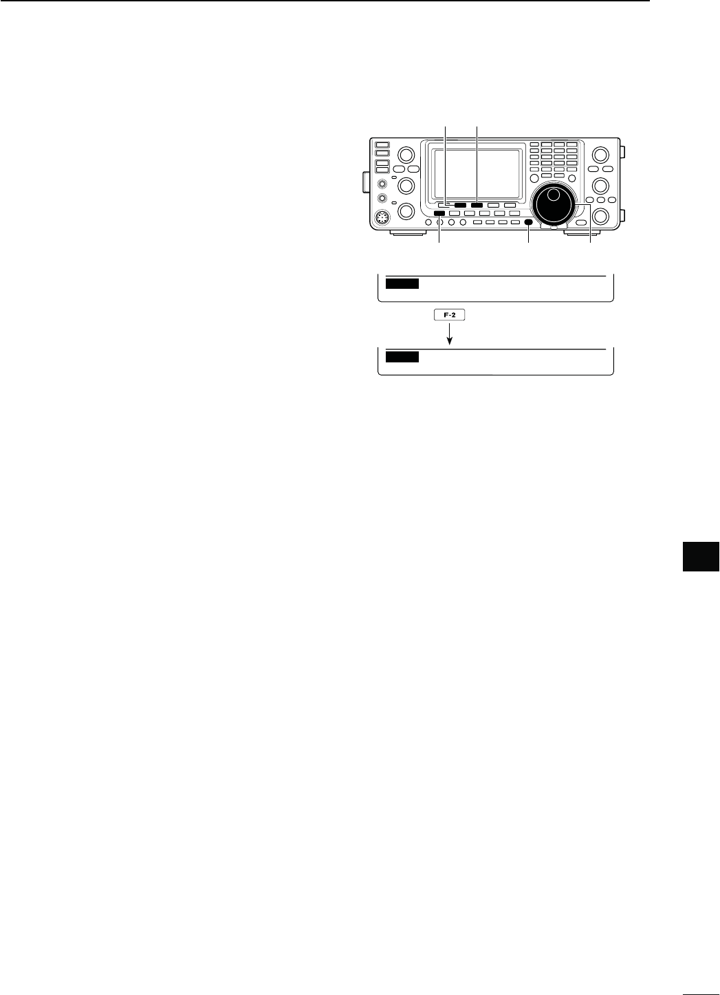
126
9
GPS/GPS-A OPERATION
9
D2ECEIVED'03MESSAGEDISPLAY
q Hold down [CALL/GPS] for 1 second to display the
“GPS” screen.
w Push [MSG](F-3) to display the “MSG” screen (GPS
Message).
e Push [RXM](F-2) to display the “RXM” screen (RX
message).
s-ESSAGESOF UPTO CHARACTERSCAN BEDISPLAYED
When the received GPS message includes more than
36 characters, push [F-1] to display the rest of the mes-
sage.
r Push [MENU] to return to the “MSG” screen (GPS
Message).
t Push [MENU] to return to the “GPS” screen.
[MSG]
[CALL/GPS] [MAIN DIAL][MENU]
[RXM]
RXMTXM
MSG
GPS Message
RXM
HELLO
Push
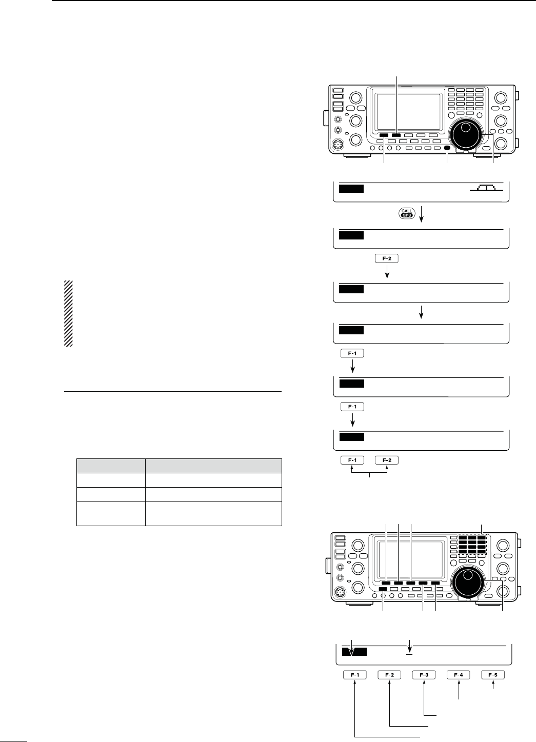
127
9GPS/GPS-A OPERATION
N'03MEMORYOPERATION
The transceiver has 50 GPS memory channels to store
the received position data, or other-used position data,
along with an alphanumeric channel name.
D!DDA'03MEMORY
q Hold down [CALL/GPS] for 1 second to display the
“GPS” screen.
w Push [GPM](F-2) to display the “GPM” screen (GPS
Memory).
e Rotate [MAIN DIAL] to select “ALL” or a desired
memory bank.
s The bank can be selected in ‘Memory bank setting,’ as
described on page 128.
r Push [LIST](F-1), then push [ADD](F-1) to enter the
“ADD” screen (GPS Memory Add) to manually add
new data.
4OCANCELTHEPROGRAMMEDDATA
When the “ADD” screen is selected, push
;-%.5=TODISPLAYh#ANCEL/+v0USH;9%3=
(F-4) to cancel programming and return to the
“GPM” screen, or push [NO](F-5) to keep pro-
gramming and return to the “ADD” screen.
t Push [Y](F-1) or [Z](F-2) to select the item.
-EMORY.AMEPROGRAMMING
q When “NAME” is selected, push [EDT](F-4) to
enter the memory name programming mode.
s!CURSORAPPEARSANDBLINKS
w Push [F-1] one or more times to select the de-
sired character type.
#HARACTERTYPE 3ELECTABLECHARACTERS
ABC A to Z
abc a to z
etc <" ’ ` ^ + – 1b
< > ( ) [ ] { } ¦ _ ¯ @
e Rotate [MAIN DIAL] to select the first character
or symbol to input.
When inputting numbers or a decimal point, push
the appropriate keypad key.
s0USH;$%,=&TODELETETHESELECTEDCHARACTER
symbol or number.
s0USH;30#=&TOINPUTASPACE
s7HENALLCHARACTERSHAVEBEENprogrammed, an
error beep sounds. If you want to reprogram, push
[Ω](F-2) or [≈](F-3) to select a character, then push
[DEL](F-4) to delete it.
r Push [Ω](F-2) to move the cursor backward, or
push [≈](F-3) to move the cursor forward.
t Repeat steps w through r to program a name
of up to 9 characters.
y Push [MENU] to save the programmed name,
and return to the “ADD” screen.
[CALL/GPS] [MAIN DIAL][LIST]/[ADD]/[]
[GPM]/[]
GPMPOS MSG SET
GPS
Push
LIST CLR ALM
GPM
ALL
DUPAGC AFC TON SCP
M1
Hold down
ALM
GPM
RX
Rotate [MAIN DIAL]
Push
EDTADD CLR ALM
GPM
00:
Push
ÚÙ EDT WR
ADD
NAME:
[][][F-1]
[DEL][MENU] [SPC] [MAIN DIAL]
Keypad
s4OPROGRAMA'03MEMORYNAME
abc
DEL SPC
ADD
NAME:
Character type Cursor
Input a space
Delete a character
Move cursor forward
Move cursor backward
Select the character type
Select the item
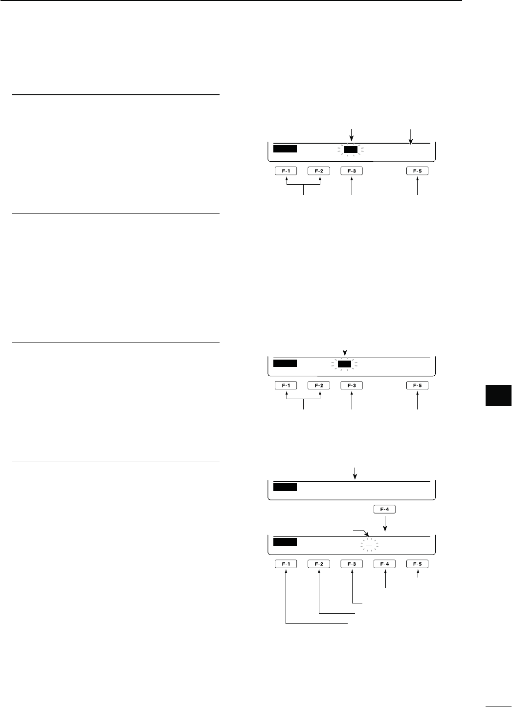
128
9
GPS/GPS-A OPERATION
9
,ATITUDEDATAPROGRAMMING
u When “LAT” is selected, rotate [MAIN DIAL] to
enter the desired latitude data.
s!CURSORBLINKSONTHEPROGRAMMABLEDIGIT
s0USH;Ω ≈](F-3) to select the digit.
s3ELECTh.vTOINPUT..ORTHLATITUDE
s3ELECTh3vTOINPUT33OUTHLATITUDE
s9OUCANNOTUSETHEKEYPADKEYS
i Push [Y](F-1) or [Z](F-2) to save the pro-
grammed latitude data, and select other item.
,ONGITUDEDATAPROGRAMMING
o When “LON” is selected, rotate [MAIN DIAL] to
enter the desired longitude data.
s!CURSORBLINKSONTHEPROGRAMMABLEDIGIT
s0USH;Ω ≈](F-3) to select the digit.
s3ELECTh7vTOINPUT77ESTLONGITUDE
s3ELECTh%vTOINPUT%%ASTLONGITUDE
s9OUCANNOTUSETHEKEYPADKEYS
!0 Push [Y](F-1) or [Z](F-2) to save the pro-
grammed longitude data, and select other
items.
4IMEDATAPROGRAMMING
!1 When “TIME” is selected, rotate [MAIN DIAL] to
enter the desired time data.
s!CURSORBLINKSONTHEPROGRAMMABLEDIGIT
s0USH;Ω ≈] to move the cursor forward and back-
ward.
s9OUCANNOTUSETHEKEYPADKEYS
!2 Push [Y](F-1) or [Z](F-2) to save the pro-
grammed time data, and select other item.
-EMORYBANKSETTING
!3 When “BANK” is selected, rotate [MAIN DIAL] to
select the desired bank letter.
!4 Push [EDT](F-4) to enter the bank name pro-
gramming mode.
s!CURSORAPPEARSANDBLINKS
!5 Repeat steps w through r of ‘Name programming’
on the previous page to program a bank name of
up to 9 characters.
!6 Push [MENU] to save the programmed bank
name, and return to the “ADD” screen.
t After programming, hold down [WR](F-5) for 1 sec-
ond to write the data into the GPS memory, and
return to the “GPM” screen (GPS Memory).
y Push [MENU] two times to return to the “GPS”
screen.
ÚÙ WR
ADD
LAT : º
00.
00’
N
s4OPROGRAMALATITUDEORLONGITUDE
Select the item
Select the digit Write into the
GPS memory
Blinks
(This illustration is based on entering a latitude.)
North latitude
is selected.
s4OPROGRAMATIMEDATA
ÚÙ WR
ADD
TIME: :−−:−−
Select the item
Select the digit Write into the
GPS memory
Blinks
s4OPROGRAMABANKNAME
ÚÙ EDT WR
ADD
BANK:
A
Bank A is selected.
Push
abc
DEL SPC
ADD
BANK:
A
Input a space
Delete a character
Move cursor forward
Move cursor backward
Select the character type
Blinks
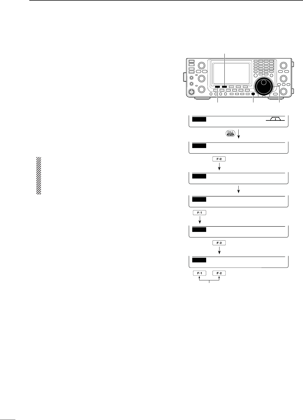
129
9GPS/GPS-A OPERATION
N GPS memory operation (Continued)
D%DITA'03MEMORY
The GPS memory name, latitude and longitude data,
time data and a memory bank name can be edited.
q Hold down [CALL/GPS] for 1 second to display the
“GPS” screen.
w Push [GPM](F-2) to display the “GPM” screen (GPS
Memory).
e Rotate [MAIN DIAL] to select “ALL” or desired mem-
ory bank.
s The bank can be selected in ‘Memory bank setting,’ as
described on page 128.
r Push [LIST](F-1), then push [EDT](F-2) to enter the
“EDT” screen (GPS Memory Edit) to edit the pro-
gramed data.
sh"LANKvAPPEARSWHENNOMEMORYISPROGRAMMED
4OCANCELTHEPROGRAMMEDDATA
When the “EDT” screen is selected, push [MENU]
TODISPLAYh#ANCEL/+v0USH;9%3=&TOCAN-
cel programming and return to the “GPM” screen,
or push [NO](F-5) to keep programming and re-
turn to the “ADD” screen.
t Push [Y](F-1) or [Z](F-2) to select the item.
y Enter a memory name, latitude data, longitude
data, time and memory bank name, as described in
steps q to !6 of ‘D Add a GPS memory’ on pages
127 and 128.
u After programming, hold down [WR](F-5) for 1 sec-
ond to write the data into the GPS memory, and
return to the “GPM” screen (GPS Memory).
y Push [MENU] two times to return to the “GPS”
screen.
[CALL/GPS] [MAIN DIAL][LIST]/[]
[GPM]/[EDT]/[]
GPMPOS MSG SET
GPS
Push
LIST CLR ALM
GPM
ALL
DUPAGC AFC TON SCP
M1
Hold down
ALM
GPM
RX
Rotate [MAIN DIAL]
Push
EDTADD CLR ALM
GPM
00:
Push
ÚÙ EDT WR
EDT
NAME:
Select the item
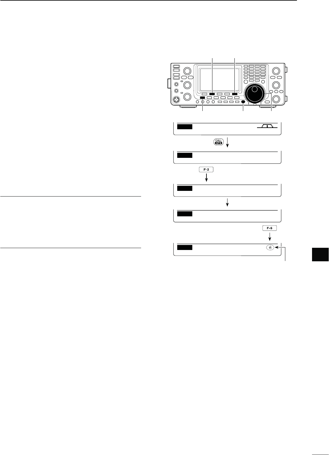
130
9
GPS/GPS-A OPERATION
9
D'03ALARMSETTING
A GPS alarm can sound when a target position comes
into the alarm area. This function can be set to the
caller station, all GPS Memory channels, a specified
Memory bank or a specified Memory channel.
q Hold down [CALL/GPS] for 1 second to display the
“GPS” screen.
w Push [GPM](F-2) to display the “GPM” screen (GPS
Memory).
e Rotate [MAIN DIAL] to select the desired memory
group, or memory channel.
sh28vh!,,vAMEMORYBANKORMEMORYCHANNELCANBE
selected.
9OUCANSELECTAMEMORYCHANNELAFTERPUSHING;,)34=
(F-1) when “ALL” or a memory bank is selected.
r Push [ALM](F-5) to turn ON the Alarm function.
s0USH;!,-=&AGAINTOTURN/&&THE!LARMFUNCTION
t Push [MENU] to return to the “GPS” screen.
For your information!
s7HENh28vORMEMORYCHANNELISSELECTEDINSTEPe,
the alarm functions depend on “Alarm Area2” setting
in the GPS Set mode. (p. 133)
s7HENh!,,vORAMEMORYBANKISSELECTEDINSTEPe,
the alarm functions depend on “Alarm Area1” setting
in the GPS Set mode. (p. 133)
[CALL/GPS] [MAIN DIAL][MENU]
[GPM] [ALM]
GPMPOS MSG SET
GPS
Push
DUPAGC AFC TON SCP
M1
Hold down
ALM
GPM
RX
Rotate [MAIN DIAL]
LIST CLR ALM
GPM
ALL
Push
LIST CLR ALM
GPM
ALL
Appears when the Alarm function is ON.
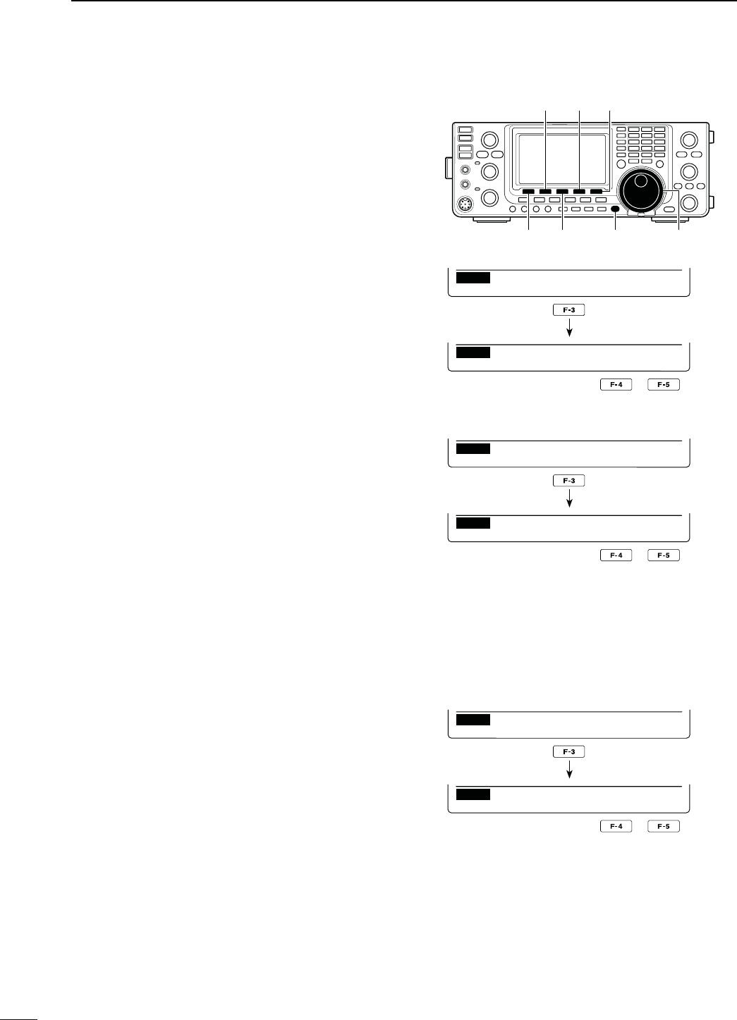
131
9GPS/GPS-A OPERATION
N GPS memory operation (Continued)
D'03MEMORYCLEARING
s#LEARALLMEMORYCHANNELS
q Hold down [CALL/GPS] for 1 second to display the
“GPS” screen.
w Push [GPM](F-2) to display the “GPM” screen (GPS
Memory).
e Rotate [MAIN DIAL] to select “ALL.”
r Hold down [CLR](F-3) for 1 second to clear all
Memory channels.
sh!,,#LEAR/+vAPPEARS
t0USH;9%3=&FORSECONDTOCLEAR
sTo cancel clearing, push [NO](F-5).
y Push [MENU] two times to return to the “GPS”
screen.
s#LEARADESIREDBANK
q Hold down [CALL/GPS] for 1 second to display the
“GPS” screen.
w Push [GPM](F-2) to display the “GPM” screen (GPS
Memory).
e Rotate [MAIN DIAL] to select the desired Memory
bank.
r Hold down [CLR](F-3) for 1 second to clear the se-
lected Memory bank.
sh"!.+#LEAR/+vAPPEARS
t0USH;9%3=&FORSECONDTOCLEAR
sTo cancel clearing, push [NO](F-5).
y Push [MENU] two times to return to the “GPS”
screen.
s#LEARADESIREDMEMORYCHANNEL
q Hold down [CALL/GPS] for 1 second to display the
“GPS” screen.
w Push [GPM](F-2) to display the “GPM” screen (GPS
Memory).
e Rotate [MAIN DIAL] to select “ALL” or a Memory
bank, then push [LIST](F-1).
r Rotate [MAIN DIAL] to select the desired GPS
Memory channel to be cleared.
t Hold down [CLR](F-3) for 1 second to clear the se-
lected Memory channel.
sh#LEAR/+vAPPEARS
y0USH;9%3=&FORSECONDTOCLEAR
sTo cancel clearing, push [NO](F-5).
y Push [MENU] two times to return to the “GPS”
screen.
[CALL/GPS] [MAIN DIAL][CLR][LIST]
[GPM] [YES] [NO]
LIST CLR ALM
GPM
ALL
Hold down
YES NO
GPM
ALL Clear OK?
EDTADD CLR ALM
GPM
00:
Hold down
YES NO
GPM
Clear OK?
LIST CLR ALM
GPM
A :
Hold down
YES NO
GPM
BANK Clear OK?
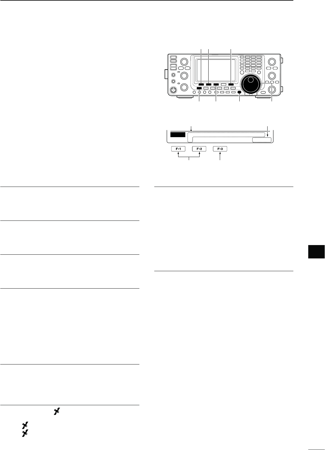
132
9
GPS/GPS-A OPERATION
9
N GPS Set mode
The following individual settings are selectable in the
GPS Set mode. Set them to suit your GPS operating
needs.
q Hold down [CALL/GPS] for 1 second to display the
“GPS” screen.
w Push [SET](F-5) to enter the GPS Set mode.
e Push [Y](F-1) or [Z](F-2) to select the desired
item.
r Rotate [MAIN DIAL] to select the desired option.
s(OLDDOWN;&=FORSECONDTORESETTOTHEDEFAULTSET-
ting, if desired.
t Push [MENU] to save, and return to the “GPS”
screen.
'032ECEIVER"AUD1. $EFAULT
Set the baud rate of the GPS receiver to 4800 bps or
9600 bps.
0OSITION&ORMAT2. $EFAULTDDD°mm.mm’
Select either the ddd°mm.mm’ or ddd°mm’ss" format
to display position information.
5NITS3. $EFAULTFEETMILE
Select either meter or feet/mile format to display the
distance and elevation information.
#/-0!33$IRECTION4. $EFAULT.ORTH2%&
Select the compass display type.
When the position data is displayed, push [F-1] to se-
lect the compass type.
s.ORTH2%&4HE TOP OF THE COMPASS REPRESENTS
north.
s3OUTH2%&4HE TOP OF THE COMPASS REPRESENTS
south.
54#/FFSET5. $EFAULTÒ
Set the time difference between UTC (Universal Time
Coordinated) and the local time to between –14:00
and +14:00 in 00:05 steps.
'03)NDICATOR6. $EFAULT/.
Turn the GPS icon (“ ”) display function ON or OFF.
s/&&h ” does not appear.
s/. h ” appears on the display when a valid po-
SITIONDATAISRECEIVEDBLINKSWHENANINVALID
data is received.
-90OSITION7. $EFAULT'03
Select either GPS or Manual to enter your current po-
sition.
s'03 4HE'03RECEIVERSPOSITIONDATAISUSED
s-ANUAL-ANUALLY ENTERED POSITION DATA IS USED
However, when the GPS receiver is con-
nected to the transceiver, this setting will
automatically switch to “GPS.”
-ANUAL0OSITION8. $EFAULT,!4 ’N
,/.’%
Manually enter your latitude and longitude data. The
manually programmed data can be memorised.
This item does not appear when “GPS” is selected in
“My Position.”
q Push [EDT](F-4) to enter the position data edit
mode.
w Push [Y](F-1) or [Z](F-2) to select “LAT” or “LON,”
and rotate [MAIN DIAL] to enter the desired posi-
tion data.
s7HENh,!4vISSELECTEDENTERTHELATITUDEDATA
s7HENh,/.vISSELECTEDENTERTHELONGITUDEDATA
s3EEPAGEFORDETAILS
e Hold down [WR](F-5) to write the data.
Select the item Reset to the default
setting
[]
[MENU] [F-3] [MAIN DIAL]
[] [SET][]
[CALL/GPS]
Ù
1
Ú4800
SET GPS Receiver Baud
Displays the Set mode
item name and number Displays the option
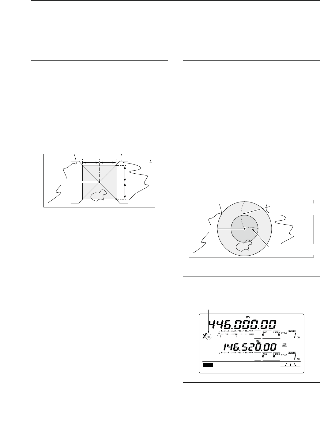
133
9GPS/GPS-A OPERATION
N GPS Set mode (Continued)
!LARM!REA9. $EFAULTg
When the GPS Alarm function is set to “ALL” or one of
the memory banks, set the GPS alarm active range.
When ddd°mm.mm’ is selected in “Position Format,”
the active range can be set to between 00’08" and
59’99" in 00’01" steps.
When ddd°mm’ss" is selected in “Position Format,” the
active range can be set to between 00’05" and 59’59"
in 00’01" steps.
See page 132 for details.
00.25’ 00.25’
00.25’00.25’
Your position
Point A
Point C
Point B
Point D
N
( This description is based on the ddd°mm.mm’ posi-
tion formatP
When a target position enters the alarm area, the GPS
alarm sounds.
!LARM!REA10. $EFAULT"OTH
When the GPS Alarm function is set to the memory
channel or “RX,” set the GPS alarm active range to
“Both,” “Extended” or “Limited.”
s,IMITED 7HENTHETARGETPOSITIONISINTHEAP-
proximate 500 meter range, the GPS
alarm sounds three times.
s%XTENDED 7HENTHETARGETPOSITIONISINTHEAP-
proximate 1 kilometer range, the GPS
alarm sounds three times.
s"OTH 7HENTHETARGETPOSITIONISINTHEAP-
proximate 1 kilometer range, the GPS
alarm sounds one beep, and when it is
in the approximate 500 meter range, the
alarm sounds three beeps.
500 meter (547 yard)
1 kilometer (1094 yard)
Extended range
(approx. 1 km; 1094 Y
)
Limited range
(approx. 500 m; 547 Y)
Your position
The target position definitions for Alarm Area 2.
!LARMINDICATION
When a target position comes into the alarm area,
the icon below appears.
AGC DUP AFC TON SCP
M1
s0OSITIONOFPOINT! .%
s0OSITIONOFPOINT" .%
s0OSITIONOFPOINT# .%
s0OSITIONOFPOINT$ .%
s%XAMPLE 9OURPOSITION .%
Alarm Area1 setting : 00.25’
s%XAMPLE
Blinks

134
9
GPS/GPS-A OPERATION
9
GPS Auto TX 11. $EFAULT/&&
Select the desired interval from OFF, 5, 10, 30 sec-
onds, 1, 3, 5, 10 or 30 minutes for automatic position
data transmission.
The current position data, received from a GPS re-
ceiver, is transmitted at the selected interval when
“GPS” or “GPS-A” is selected as the “GPS TX Mode”
option as described below.
The GPS message is transmitted as well as the posi-
tion data, if it is programmed.
Even if this setting is set to OFF, you can manually
transmit the position data by pushing [TRANSMIT] or
[PTT] (microphone).
NOTE:
s7HENFOUR'03SENTENCES ARE SELECTED AT THE
same time, “5sec” cannot be selected.
s7HENh-ANUALvISSELECTEDINh-Y0OSITIONvTHE
current position data will not be automatically
transmitted.
GPS TX Mode 12. $EFAULT$ISABLE
Select the GPS or GPS-A operating mode to transmit
the position data from a GPS receiver, or turn OFF the
function.
NOTE: When “GPS” or “GPS-A” is selected, low-
speed data communication cannot be used.
'033ENTENCE2-#13. *1 $EFAULT/&&
Turn the GPS sentence formatter “RMC” ON or OFF.
'033ENTENCE''!14. *1 $EFAULT/.
Turn the GPS sentence formatter “GGA” ON or OFF.
'033ENTENCE',,15. *1 $EFAULT/&&
Turn the GPS sentence formatter “GLL” ON or OFF.
'033ENTENCE'3!16. *1 $EFAULT/&&
Turn the GPS sentence formatter “GSA” ON or OFF.
'033ENTENCE64'17. *1 $EFAULT/&&
Turn the GPS sentence formatter “VTG” ON or OFF.
'033ENTENCE'3618. *1 $EFAULT/&&
Turn the GPS sentence formatter “GSV” ON or OFF.
./4%FOR'03SENTENCES
s5PTOFOUR'03SENTENCESAREUSABLEATTHESAME
time.
s3EEPAGEFOR'03SENTENCESETTINGDETAILS
5NPROTO!DDRESS19. *2
$EFAULT!0)$34!21
Enter an unproto address of up to 56 characters. The
manually programmed data can be memorized.
s5NPROTOADDRESSPROGRAMMING
q Push [EDT](F-4) to enter the unproto address edit
mode.
w Push [F-1] one or more times to select the desired
character type.
#HARACTERTYPE 3ELECTABLECHARACTERS
ABC A to Z
abc a to z
etc <" ’ ` ^ + – 1b
( ) [ ] { } ¦ _ ¯ @
e Rotate [MAIN DIAL] to select the first character or
symbol to input.
s7HENENTERINGNUMBERORADECIMALPOINTPUSHTHEAP-
propriate keypad key.
s0USH;$%,=&TODELETETHESELECTEDCHARACTERSYM-
bol or number.
s0USH;30#=&TOINPUTASPACE
s7HENALL CHARACTERSHAVEBEENprogrammed, an
error beep sounds. If you want to reprogram, push [Ω]
(F-2) or [≈](F-3) to select a character, then push [DEL]
(F-4) to delete it.
r Push [Ω](F-2) to move the cursor backward, or push
[≈](F-3) to move the cursor forward.
t Repeat steps w through r to program an unproto
address of up to 56 characters.
y Push [MENU] to save the unproto address, and re-
turn to the “SET” screen.
*1 Appears when “GPS” is selected in “GPS TX Mode.”
*2 Appears when “GPS-A” is selected in “GPS TX Mode.”

135
9GPS/GPS-A OPERATION
N GPS Set mode (Continued)
$ATA%XTENSION20. * $EFAULT/&&
Set the data extension capability to “Course/Speed”
or OFF.
When you select “Course/Speed,” the transceiver’s
course and speed information is transmitted along with
the position data.
NOTE: When “Course/Speed” is selected, “Com-
ment (Extension)” appears instead of “Comment,”
and number of characters is limited to 36.
4IME3TAMP21. * $EFAULT/&&
Select either the DHM or HMS format to transmit the
current UTC (Universal Time Coordinated) time as a
time stamp, or turn OFF the function.
s/&& $OESNOTTRANSMITTHETIMEINFORMATION
s$(-4RANSMITSTHETIMESTAMPINTHE$AY(OUR
and Minute format.
s(-34RANSMITSTHETIMESTAMPINTHE(OUR-INUTE
and Second format.
'03!3YMBOL22. *
$EFAULT(OUSE14(6(&
Select the desired GPS-A symbol which represents
your means of transportation.
Selectable symbols:
!MBULANCE"US&IRE4RUCK"ICYCLE9ACHT(ELICOPTER
Small Aircraft, Ship, Car, Motorcycle, Balloon, Jeep,
RV, Truck, Van, House QTH (VHF) and Other
If there is no symbol you want to use, you can make a
desired symbol code, as described below.
s3YMBOLPROGRAMMING
q Rotate [MAIN DIAL] to select “Other.”
s;%$4=&ANDTHECURRENTSYMBOLCODEAPPEAR
w Push [EDT](F-4) to enter the programming mode.
s!CURSORBLINKSON“ ⁄ ”.
e Rotate [MAIN DIAL] to select the first digit character
to input.
5SABLECHARACTERSb<TO!TO:
r Push [≈](F-3) to select the second digit.
s!CURSORBLINKSON“–”.
t Push [F-1] one or more times to select the desired
character type.
#HARACTER
TYPE 3ELECTABLECHARACTERS
ABC A to Z
abc a to z
etc <" ’ ` ^ + – 1b
[ ] { } ¦ _ ¯ @ (space)
y Rotate [MAIN DIAL] to select the second digit char-
acter to input.
When inputting numbers or a decimal point, push
the appropriate keypad key.
u Push [MENU] to save the symbol code, and return
to the “SET” screen.
When “Other” is selected, check the symbol codes of
APRS®, and set them correctly.
SSID23. * $EFAULT
To assist in identifying a station’s type, the displayed
APRS® based SSID is added after the GPS-A data
call sign.
s $OESNOTUSEANY33)$(OWEVERIFYOU
use a capital letter, it will be used as an
SSID.
%XAMPLE
*!95!¨*!95!
*!95!!¨*!95!!
s .O33)$)FYOUUSEACAPITALLETTERITWILL
be deleted.
%XAMPLE
*!95!¨*!95!
*!95!!¨*!95!
sTO !DDSAN33)$OFTOTOYOURCALL
sign. If you use a capital letter, it will be
replaced with the SSID.
%XAMPLEhvISENTERED
*!95!¨*!95!
*!95!!¨*!95!
NOTE: If you have multiple transceivers, your call
signs are distinguished by a single capital letter in
the D-STAR* system. When you use an SSID, the
capital letter will be replaced by the SSID, depend-
ing on the setting.
* Appears when “GPS-A” is selected in “GPS TX Mode.”

136
9
GPS/GPS-A OPERATION
9
#OMMENT24. *
Program a comment of up to 43 characters.
The programmed comment is transmitted with the
GPS position data.
See ‘Comment programming,’ as described below.
This item appears when “Data Extension” is set to
OFF, as described on page 135.
#OMMENT%XTENSION25. *
Program a comment of up to 36 characters.
The programmed comment is transmitted with the
GPS position data.
See ‘Comment programming,’ as described below.
This item appears when “Course/Speed” is selected in
“Data Extension,” as described on page 135.
s#OMMENTPROGRAMMING
q Push [EDT](F-4) to enter the programming mode.
s!CURSORAPPEARSANDBLINKS
w Push [F-1] one or more times to select the desired
character type.
#HARACTERTYPE 3ELECTABLECHARACTERS
ABC A to Z
abc a to z
etc <" ’ ` ^ + – 1b
( ) [ ] { } ¦ _ ¯ @
e Rotate [MAIN DIAL] to select the first character or
symbol to enter.
When inputting numbers or a decimal point, push
the appropriate keypad key.
s0USH;$%,=&TODELETETHESELECTEDCHARACTERSYM-
bol or number.
s0USH;30#=&TOINPUTASPACE
s7HENALLORCHARACTERSHAVEBEENprogrammed,
an error beep sounds. If you want to reprogram, push
[Ω](F-2) or [≈](F-3) to select a character, then push
[DEL](F-4) to delete it.
r Push [Ω](F-2) to move the cursor backward, or push
[≈](F-3) to move the cursor forward.
t Repeat steps w through r to program a comment
of up to 43 characters*.
* 36 characters can only be programmed when “Course/
Speed” is selected in “Data Extension.”
y Push [MENU] to save the comment, and return to
the “SET” screen.

137
9GPS/GPS-A OPERATION
N'03!OPERATION
D'03!FUNCTION
Set the following to activate the GPS-A function.
q Push [DVsDR] to select the DV mode.
w Enter the GPS Set mode.
e Set the desired position data transmitting interval in
“GPS Auto TX.” (p. 134)
r Select “GPS-A” in “GPS TX Mode.” (p. 134)
t Set the GPS-A mode operation’s items. (pp. 134–
136)
D'03!CODEDETAILS
In GPS-A operation, the following codes are transmit-
ted to the PC connected to the IC-9100.
GPS-A code is based on APRS® code.
(APRS® : Automatic Position Reporting System)
JA3YU!!0)$34AR∗H.%)AMHERE#ANYOUSEEME
9our own call sign
Unproto address
Time stamp
Time stamp H H.M.S (Hour/Minute/Second)
Z D.H.M (Day/Hour/Minute)
Latitude
Longitude
Data extension
Comment
GPS-A symbol (Car)
s'03!CODEDETAILS
7HENCONNECTINGTHE0#WITHTHE53"PORT
Connect a USB cable* between the transceiver’s USB
port on the rear panel and the PC. (p. 26)
When “DV dat” is selected as the “USB2/DATA1 Func”
(63) item option, the GPS-A data can be send from the
USB port. (p. 167)
* Purchase separately
7HENCONNECTINGTHE0#WITHTHE;$!4!=JACK
Connect the optional OPC-1529R between the trans-
ceiver’s [DATA1] jack on the rear panel and the PC.
(p. 26)
When “DV dat” is selected as the “USB2/DATA1 Func”
(64) item option, the GPS-A data can be send from the
[DATA1] port. (p. 168)
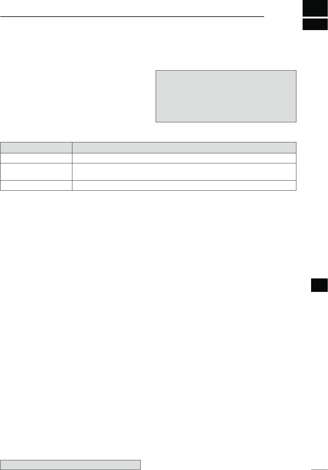
10
138
MEMORY OPERATION
10
N'ENERALDESCRIPTION
The transceiver has 106 Memory channels in each fre-
quency band. (99 regular, 6 scan edges and 1 call)
The Memory mode is very useful to quickly change to
often-used frequencies.
While in the memory mode, all 106 Memory channels
are tunable, which means the programmed frequency
can be tuned temporarily with [MAIN DIAL].
NOTE:
Memory data can be erased by static electricity, elec-
tric transients, etc. In addition, they can be erased by
malfunction and during repairs. Therefore, we recom-
mend that memory data be backed up or be saved
to a PC using the optional CS-9100 CLONING SOFT-
WARE.
-EMORY#HANNELS $ESCRIPTIONS
1–99 Regular Memory channels with Split frequency capability.*
1A/1b–3A/3b Program Scan Edge Memory channels with only Simplex capability.
Stores the scan edge frequencies for programmed scans.
C Call channel with Split frequency capability*. Instantly recalls a specified frequency.
*Usable only on HF/50 MHz frequency bands.
D-EMORYCHANNELCONTENTS
The following information can be programmed into
Memory channels:
s/PERATINGFREQUENCYP
s/PERATINGMODEP
s)&lLTERNUMBERP
s3PLITDATAP
( Usable only on the regular Memory channels and
Call channel on HF/50 MHz frequency bands.)
s-EMORYNAMEP
s$UPLEXDIRECTION$50ORn$50ANDFREQUENCYOFF-
set (pp. 65, 163)
s3UBAUDIBLETONEENCODERPTONESQUELCHOR
DTCS squelch ON/OFF (pp. 62, 63)
s3UBAUDIBLETONEFREQUENCYPTONESQUELCHFRE-
quency or DTCS code with polarity (pp. 62, 63)
s523TATIONCALLSIGNP
s22CALLSIGNP
s#ALLSIGNSQUELCHOR$IGITALCODESQUELCH/./&&
(p. 114)
s$IGITALCODEP
The optional UT-121 is required for DV mode operation.
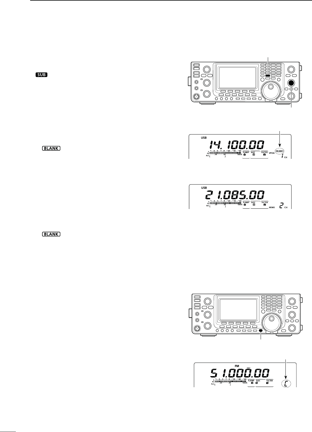
139
10 -%-/29/0%2!4)/.
N-EMORYCHANNELSELECTION
W
hen the SUB Band setting is turned ON, y
ou can se-
lect a Memory channel in the SUB Band as well as in
the MAIN Band
. (p. 33)
sh ” appears when the SUB Band setting is ON.
D3ELECTIONINTHE6&/MODE
q Push [VFO/MEMO] to select the VFO mode.
w Rotate [M-CH] to select a Memory channel num-
ber.
s2OTATECLOCKWISETOSELECTAHIGHER-EMORYCHANNEL
NUMBERROTATECOUNTERCLOCKWISETOSELECTALOWER-EM-
ory channel number.
s!LL-EMORYCHANNELSINCLUDINGBLANKCHANNELSCANBE
selected.
sh” appears when no information has been pro-
grammed into the Memory channel. (Blank channel)
e Push [VFO/MEMO] to select the Memory mode.
sh-%-/vANDCONTENTSOFTHE-EMORYCHANNELAPPEAR
D3ELECTIONINTHE-EMORYMODE
q Push [VFO/MEMO] to select the Memory mode.
w Rotate [M-CH] to select a Memory channel.
s2OTATECLOCKWISETOSELECTAHIGHER-EMORYCHANNEL
NUMBERROTATECOUNTERCLOCKWISETOSELECTALOWER-EM-
ory channel number.
s!LL-EMORYCHANNELSINCLUDINGBLANKCHANNELSCANBE
selected.
sh” appears when no information has been pro-
grammed into the Memory channel. (Blank channel)
s-EMORYCHANNELSCANALSOBESELECTEDUSINGTHEMICRO-
phone [UP]/[DN] keys. In such case, the blank channels
are skipped.
[VFO/MEMO]
[M-CH]
While in the VFO mode
Appears if the selected Memory
channel has no information.
While in the Memory mode
N#ALLCHANNELSELECTION
Each frequency band has its own Call channel. Fac-
tory default frequency and operating modes are pro-
grammed into the Call channel. Change these to suit
your operating needs. (see page 141)
q0USH;#!,,s'03=TOSELECTTHE#ALLCHANNEL
s!CAPITALh#vAPPEARS
w 0USH;#!,,s'03=AGAINTORETURNTOTHEPREVIOUS
screen display.
Appears
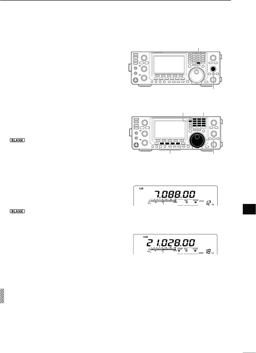
140
10
-%-/29/0%2!4)/.
10
Memory channels can be programmed in either the
VFO mode or the Memory mode.
D0ROGRAMMINGINTHE6&/MODE
q Push [VFO/MEMO] to select the VFO mode.
w Set the desired settings into both VFO A and VFO
B.
± Select the band using [BAND](MAIN/SUB).
± Set the frequency with [MAIN DIAL] or the key-
pad. (p. 37)
± Set the operating mode with the mode switch.
(p. 43)
± Set other data (e.g. frequency offset, duplex di-
rection, tone squelch, split frequency operation,
etc.), if desired. (p. 138)
e Rotate [M-CH] to select the Memory channel num-
ber to be programmed.
sh” appears if the selected Memory channel is a
blank channel.
r Hold down [MW] for 1 second to program the con-
tents into the Memory channel.
s4HREEBEEPSSOUNDWHENTHEmemory programming is
complete.
D0ROGRAMMINGINTHE-EMORYMODE
q Push [VFO/MEMO] to select the Memory mode.
w Rotate [M-CH] to select the Memory channel to be
programmed.
s4HECONTENTSOFTHE-EMORYCHANNELAPPEARINTHEDIS-
play.
sh” appears if the selected Memory channel is a
blank channel.
e Set the desired settings into the Memory channel.
± Set the frequency with [MAIN DIAL] or the key-
pad. (p. 37)
s7HENABLANKCHANNELISSELECTEDYOUMUSTSETTHE
desired frequency using the keypad.
± Set the operating mode with the mode switch.
± Set other data (e.g. frequency offset, duplex di-
rection, tone squelch, etc.), if desired.
r Hold down [MW] for 1 second to program the con-
tents into the Memory channel.
s4HREEBEEPSSOUNDWHENTHEMEMORYPROGRAMMINGIS
complete.
NOTE: If you perform the above operations in a pre-
programmed channel, the previous channel data will
be overwritten.
N-EMORYCHANNELPROGRAMMING
[MW]
[M-CH]
[EXAMPLE]:
Programming 7.088 MHz/LSB into the Mem-
ory channel 12 while in the VFO mode.
[EXAMPLE]:
Programming 21.280 MHz/USB into Memory
channel 18 while in the Memory mode.
s$URINGSETTINGTHECONTENTS
[MAIN DIAL]
Keypad[BAND](MAIN/SUB)
Mode selection
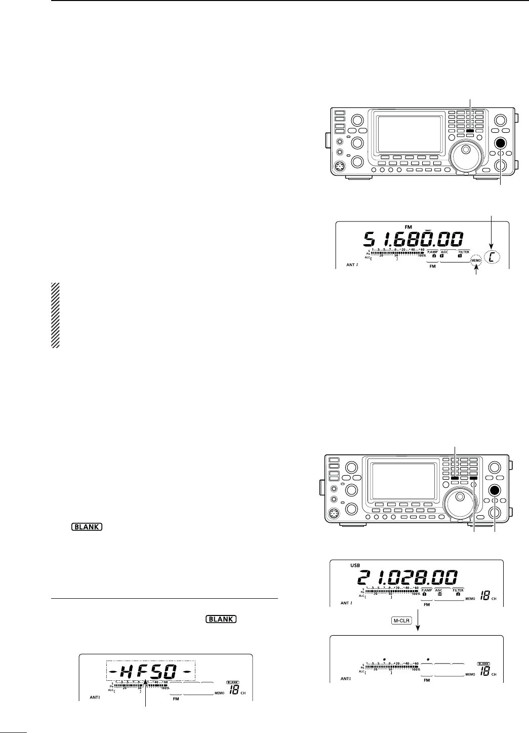
141
10 -%-/29/0%2!4)/.
N#ALLCHANNELPROGRAMMING
The Call channel is programmed in the same way as
the regular Memory channels are. It is convenient to
program a most-often-used frequency into the Call
channel for quick recall. As with Memory channels, the
Call channel can also hold split frequencies, and other
parameters. See page 138 for details.
q Rotate [M-CH] to select the Call channel.
sA capital “C” appears.
w Select the desired frequency and operating mode
to program into the Call channel.
e Hold down [MW] for 1 second to program the dis-
played frequency and operating mode into the Call
channel.
s4HREEBEEPSSOUNDWHENMEMORYPROGRAMMINGISCOM-
plete.
IMPORTANT!
7HENTHE#ALLCHANNELISSELECTEDWITH;#!,,s'03=
you cannot change the memory contents. However,
when the Call channel is selected using [M-CH] in
the VFO or Memory mode, the memory contents
can be changed.
[MW]
[M-CH]
Appears
Appears
[VFO/MEMO]
[M-CH][M-CLR]
Hold down
The operating band appears.
N-EMORYCLEARING
Any no-longer-used regular Memory channels can be
cleared, and then become blank channels.
q Push [VFO/MEMO] to select the Memory mode.
w Rotate [M-CH] to select the regular Memory chan-
nel to be cleared.
e Hold down [M-CLR] for 1 second to clear the con-
tents.
s4HEPROGRAMMEDCONTENTSDISAPPEAR
sh” appears.
s4HREEBEEPSSOUNDWHENTHEMEMORYCLEARINGISCOM-
plete.
r To clear other Memory channels, repeat steps w
and e.
!BOUTTHEBLANKCHANNELDISPLAY
When a blank channel is selected, or after clearing
the Memory channel contents, the “ ” icon ap-
pears, and then after 2 seconds, the operating band
appears.
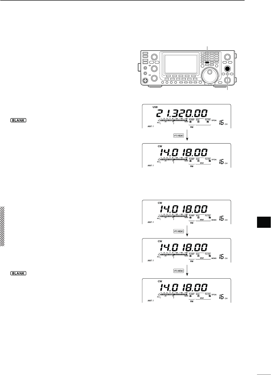
142
10
-%-/29/0%2!4)/.
10
The Memory channel contents (frequency, operating
mode, etc.) can be copied to the VFO.
The copy can be performed in either the VFO mode or
the Memory mode.
D#OPYINGINTHE6&/MODE
This is useful for copying programmed contents to
a displayed VFO.
q Push [VFO/MEMO] to select the VFO mode.
w Rotate [M-CH] to select the Memory channel num-
ber to be copied.
sh” appears if the selected Memory channel is a
blank channel. In this case nothing can be copied.
e Hold down [VFO/MEMO] for 1 second to copy the
Memory channel contents into the VFO.
s4HREEBEEPSSOUNDWHENTHECOPYISCOMPLETE
D#OPYINGINTHE-EMORYMODE
This is useful for copying the Memory channel con-
tents while operating in the Memory mode.
When you have changed the displayed frequency,
operating mode, etc. in the selected Memory chan-
nel:
s$ISPLAYEDdata is copied.
s0ROGRAMMEDcontents in the Memory channel are
not copied, but remain only in the Memory chan-
nel.
q Push [VFO/MEMO] to select the Memory mode.
w Rotate [M-CH] to select the Memory channel to be
copied.
sh” appears if the selected Memory channel is a
blank channel. In this case nothing can be copied.
s3ETTHEFREQUENCYOROPERATINGMODEIFREQUIRED
e Hold down [VFO/MEMO] for 1 second to copy the
Memory channel contents into the VFO.
s4HREEBEEPSSOUNDWHENTHETRANSFERISCOMPLETE
r Push [VFO/MEMO] to select the VFO mode.
[VFO/MEMO]
[M-CH]
Hold down
Push
While in the Memory mode
The Memory channel contents are transferred
Hold down
While in the VFO mode
The Memory channel contents are transferred
N-EMORYCONTENTSCOPYING
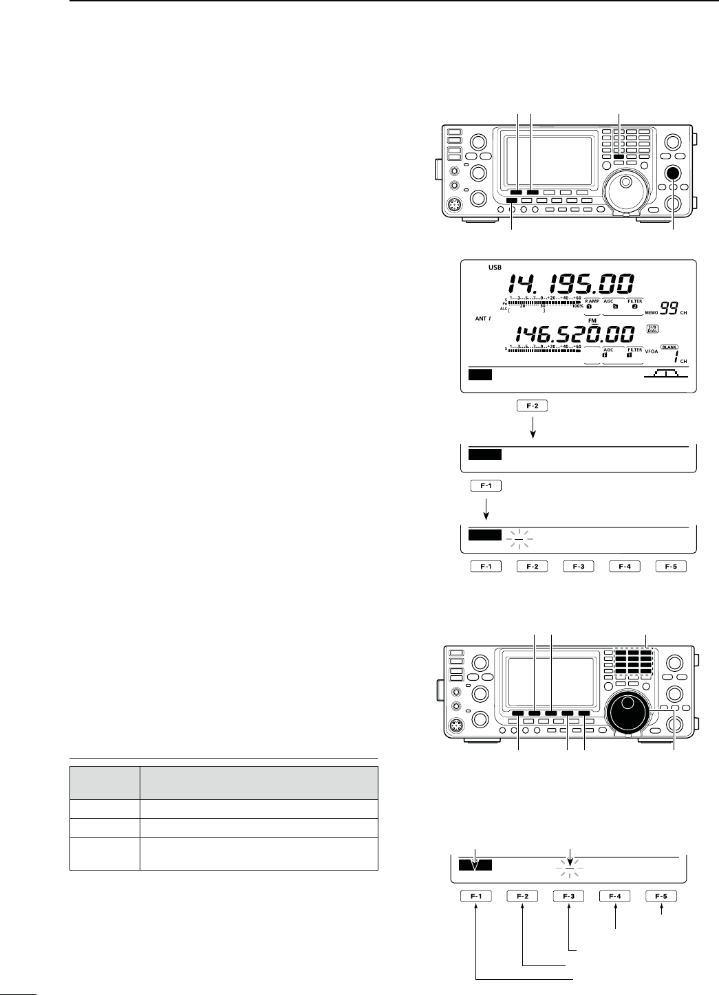
143
10 -%-/29/0%2!4)/.
N-EMORYNAMEPROGRAMMING
All Memory channels, including scan edges and Call
channel, can be tagged with alphanumeric names of
up to 9 characters each.
[EXAMPLE]: Programming a memory name into
Memory channel 99.
q Push [VFO/MEMO] to select the Memory mode.
w Rotate [M-CH] to select Memory channel 99.
e Push [MENU] one or more times to display the “M2”
screen (Menu 2).
r Push [MEM](F-2) to display the “MEM” screen
(Memory Menu).
t Push [EDT](F-1) to display the “EDT” screen (Mem-
ory name Edit).
s!CURSORAPPEARSANDBLINKS
s)FTHECHANNELYOUSELECTISABLANKCHANNELANERROR
beep sounds after pushing [EDT](F1).
y Push [F-1] one or more times to select the desired
character type.
s3EEh#HARACTERTABLELISTvASSHOWNBELOW
u Rotate [MAIN DIAL] to select the first character or
symbol to input.
When inputting numbers and a decimal point, push
the appropriate keypad key.
s0USH;$%,=&TODELETETHESELECTEDCHARACTERSYM-
bol or number.
s0USH;30#=&TOINPUTASPACE
s7HENALLCHARACTERSHAVEBEENprogrammed, an error
beep sounds. If you want to reprogram, push [Ω](F-2) or
[≈](F-3) to select a character, then push [DEL](F-4) to
delete it.
i Push [Ω](F-2) to move the cursor backwards, or
push [≈](F-3) to move the cursor forwards.
o Repeat steps y to i to program a memory name
of up to 9 characters.
!0 Push [MENU] to save the name, and return to the
“MEM” screen (Memory Menu).
!1 Push [MENU] to return to the “M2” screen (Menu
2).
#HARACTERTABLELIST
#HARACTER
TYPE 3ELECTABLECHARACTERS
ABC A to Z
abc a to z
etc <" ’ ` ^ + – 1b;=[]
¦ _ ¯ @
[VFO/MEMO] [MEM] [EDT]
[M-CH][MENU]
SCAN ME M S WR TCON VS C
M2
EDT ( ) SEL
MEM
14.19500 USB
ABC
DEL SPC
EDT
[][]
[F-1] [DEL][SPC] [MAIN DIAL]
Keypad
s7HENPROGRAMINGAMEMORYNAME
abc
DEL SPC
EDT
DX
spot
Character type Cursor
Input a space
Delete a character
Move cursor forwards
Move cursor backwards
Select character type
[EXAMPLE]: Programming “DX spot” into Memory
channel 99.
Push
Push
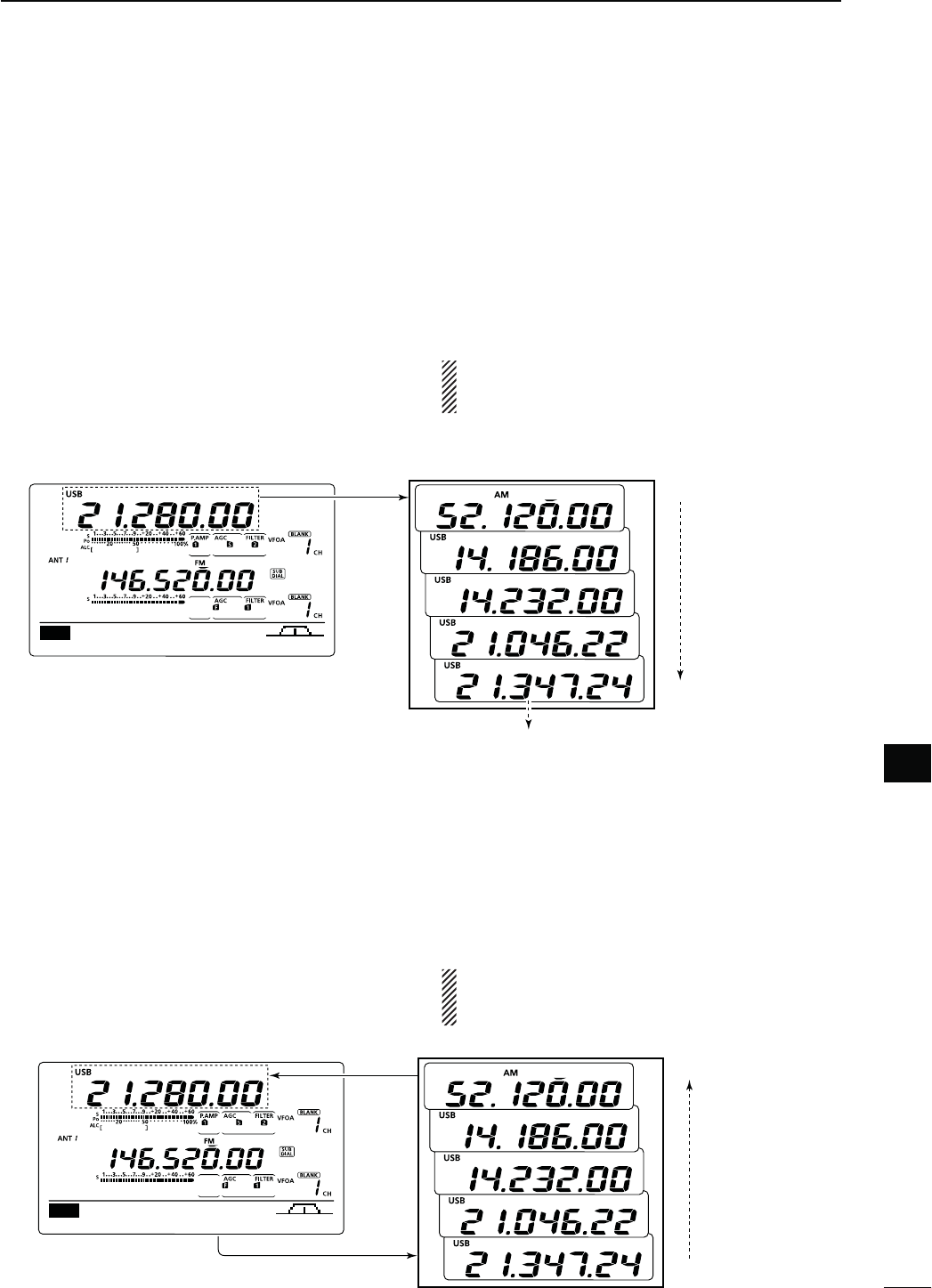
144
10
-%-/29/0%2!4)/.
10
9OUCANCALLUPAMEMOPADBYPUSHING;-02=ONEOR
more times while in either the VFO or Memory mode.
s4HEMEMOPADDATAISCALLEDUPSTARTINGFROMTHEMOST
recently written.
When you call up a memo pad, the previously dis-
played data is automatically stored in a temporary pad.
The temporary pad can be recalled by pushing [MP-R]
one or more times.
s9OUMAYTHINKTHEREAREMEMOPADSBECAUSEDIFFERENT
frequencies (5 are in memo pads and 1 is in the temporary
pad) are called up by [MP-R].
If you change the data called up from a memo pad,
the stored temporary pad data is replaced with the
changed data.
N-EMOPADFUNCTION
The transceiver has a Memo pad function to store
the displayed data for easy writing and recalling. The
memo pads are separate from the Memory channels.
The default number of memo pads is 5. However, you
can increase the number to 10 in the “Memopad Num-
bers” item of the Set mode, if desired. (p. 164)
Memo pads are convenient when you want to memo-
rize the displayed data temporarily, such as when you
find a DX station in a pile-up, or when a desired station
is busy for a long time and you want to temporarily
search for other stations.
Use the transceiver’s memo pads instead of relying on
hastily scribbled notes that are easily misplaced.
D7RITINGTHEDISPLAYEDDATAINTOMEMOPADS
9OUCANSTORETHEDISPLAYEDDATABYPUSHING;-07=
When you store the 6th data into memo pads, the old-
est stored entry is automatically erased, to make room
for the new data.
AGC DUP COMP TBW SCP
M1
In this example, 21.347 MHz (USB) will be
erased when 21.280 MHz (LSB) is written.
Memo pads
Erased
[MP-W] Newest
Oldest
AGC DUP COMP TBW SCP
M1
[MP-R] Newest
Oldest
[MP-R]
NOTE: Each memo pad must have its own unique
SETOFDATAMEMOPADSHAVINGIDENTICALDATACANNOT
be written.
D #ALLINGUPTHEMEMOPADS
Memo pads
Push
Push
Push
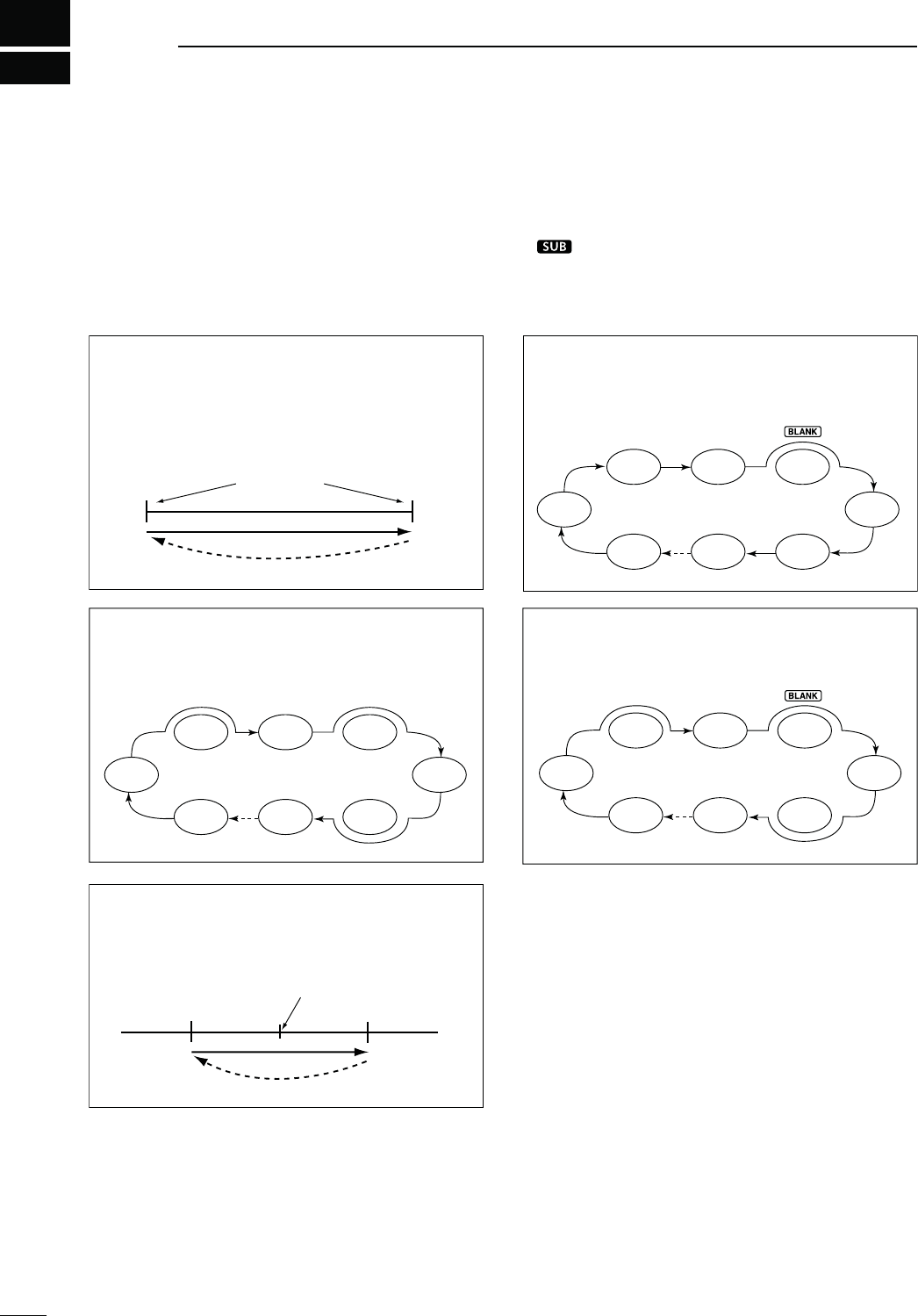
11
145
SCANS
Scan
–
∂F frequency +∂F frequency
Center frequency
(Start frequency)
Jump
Mch 1 Mch 5
Mch 2 Mch 3 Mch 4
Mch 6Mch 7Mch 99
SEL
SELSEL
SEL SEL
Mch 1 Mch 5
Mch 2 Mch 3 Mch 4
Mch 6Mch 7Mch 99
SEL
SELSEL
SEL SEL
FM FM
USB FM CW
USBFM
FM
Scan
1A
2A
3A
1b
2b
3b
Jump
Scan edges
N3CANTYPES
Scanning automatically searches for signals and
makes it easier to locate new stations for contact or lis-
TENINGPURPOSES4HE)#HASSEVERALSCANTYPES
Programmed scan, Memory scan, Select Memory
scan, Mode Select scan and ∂F (Delta Frequency)
scan.
The MAIN and SUB Bands can be independently
scanned. When the SUB Band setting mode is turned ON
(“ ” appears), the SUB Band is scanned.
MEMORY SCAN (p. 150)
Repeatedly scans all programmed Memory chan-
nels.
This scan operates in the memory mode.
PROGRAMMED SCAN (p. 149)
Repeatedly scans between scan edges. P1 scans
between 1A and 1b, P2 scans between 2A and 2b,
and P3 scans between 3A and 3b frequencies.
This scan operates in the VFO mode.
SELECT MEMORY SCAN (p. 151)
Repeatedly scans all Select Memory channels.
This scan operates in the memory mode.
MODE SELECT SCAN (p. 150)
Repeatedly scans all selected mode Memory chan-
nels.
This scan operates in the memory mode.
∂F SCAN (p. 152)
Repeatedly scans within the ∂F span area.
This scan operates in both VFO and memory
modes.

146
11
SCANS
11
N0REPARATION
&ORA0ROGRAMMEDSCAN
Program scan edge frequencies into Program Scan
Edge channels “1A–3A” and “1b–3b.” (p. 148)
&ORA-EMORYSCAN
Program two or more Memory channels. (Program
Scan Edge channels will not be scanned.) (p. 140)
&ORA-ODE3ELECTSCAN
Program two or more Memory channels, all with the
same operating mode. (p. 43)
&ORA3ELECT-EMORYSCAN
Program two or more Memory channels as Select
Memory channels. (p. 151)
&ORA∂&SCAN
Set the ∂F span (∂F scan range) in the “SCAN” screen.
(p. 152)
s3CAN2ESUMEFUNCTION
9OUCANSELECTTHESCANTORESUMEORCANCELWHENDE-
tecting a signal in the Scan Set mode. The Scan Re-
sume function must be set before operating a scan.
(p. 147)
s3CANSPEED
The scan speed can be set to high or low in the Scan
Set mode. (p. 147)
s;-!).$)!,=FUNCTION
How the [MAIN DIAL] functions during a scan, can be
set in the Scan Set mode. (p. 147)
s3QUELCHSTATUS
M4HESCANSTARTSWITHTHESQUELCHOPEN
&ORAPROGRAMMEDSCAN
When the tuning step is 1 kHz or less:
The scan continues until it is stopped manually— it
does not pause*, even if signals are detected.
* The scan is paused when the squelch is closed and then
opened. The scan resumes, or is cancelled, depending on
the Scan Resume setting.
When the tuning step is 5 kHz or more:
If Scan Resume is ON, the scan pauses on each step
when a signal is detected, then resumes.
If the Scan Resume is OFF, the scan does not start.
&ORMEMORYSCAN
If Scan Resume is ON, the scan pauses on each channel
when a signal is detected, then resumes.
If Scan Resume is OFF, the scan does not start.
M4HESCANSTARTSWITHSQUELCHCLOSED
The scan pauses when signals are detected. The scan
resumes, or is cancelled, depending on the Scan Re-
sume setting.
-ODE33"!-&-
This function is useful when you do not want unmodu-
lated signals pausing or cancelling a scan. When the
Voice Squelch Control (VSC) function is ON, the re-
ceiver checks received signals for voice components.
The scan pauses, or is cancelled, if a received signal
includes voice components, and the tone of the voice
components changes within 1 second. See “Squelch
status” as described above.
The scan resumes if the received signal includes no
voice components, or the tone of the voice compo-
nents does not change within 1 second.
q Push [SSB] or [AM/FM] once or twice to select the
operating mode.
w Push [MENU] to display the “M2” screen (Menu 2).
e Push [VSC](F-5) to turn the VSC function ON or
OFF.
sh ” appears when the VSC function is ON.
s0USH;-%.5=TORETURNTOTHEPREVIOUSDISPLAY
s4HE63#FUNCTIONISAVAILABLEFORPHONEMODES
(SSB, AM and FM).
s4HE63#FUNCTIONRESUMESTHESCANONUNMODU-
lated signals, regardless of whether the Scan Re-
sume function is set to ON or OFF.
N6OICE3QUELCH#ONTROLFUNCTION
SCAN ME M S WR TCON VS C
M2
Appears
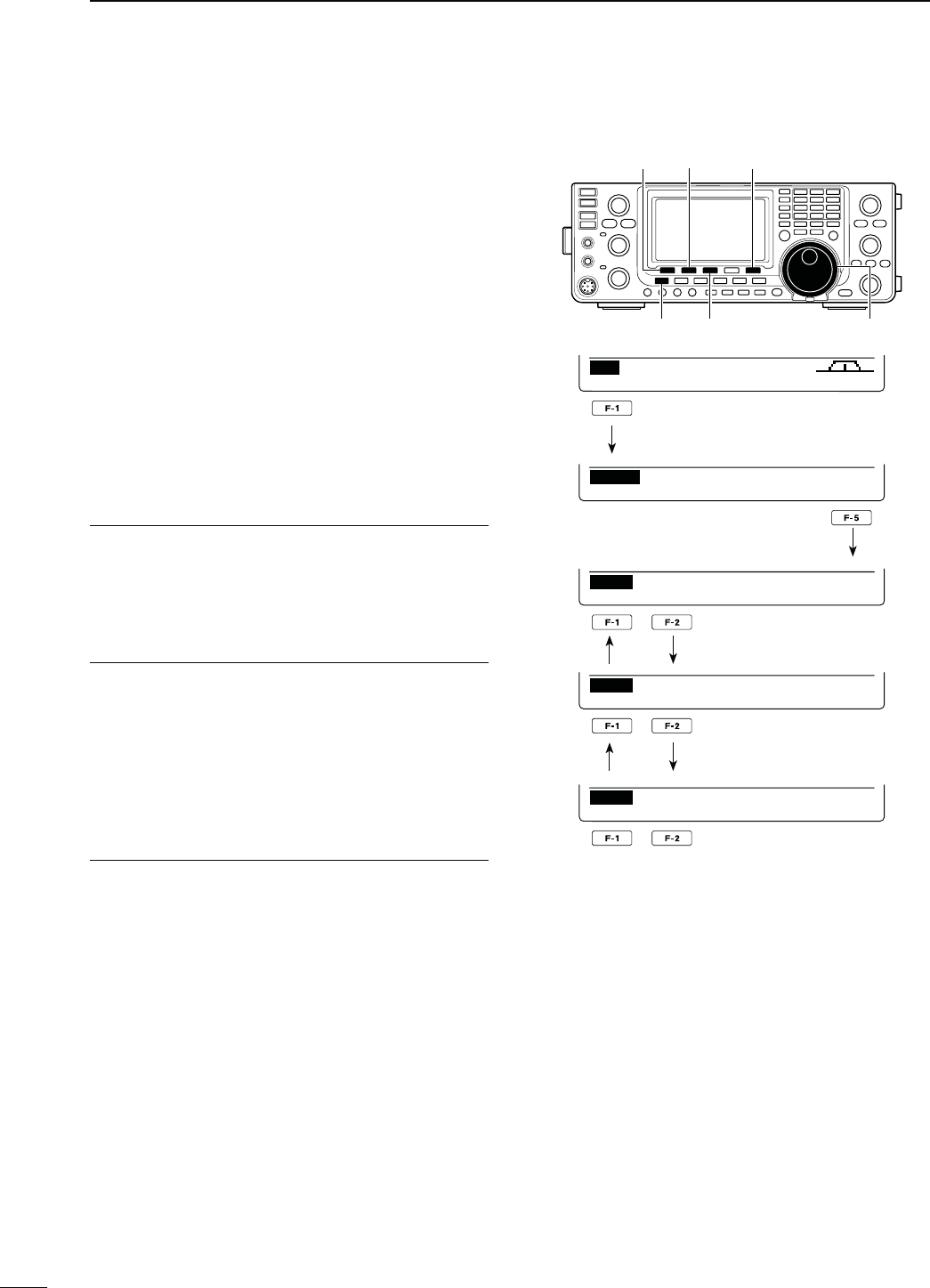
147
11 SCANS
N3CANSETMODE
The scan speed, Scan Resume function and [MAIN
DIAL] scan function can be set in the Scan Set mode.
q
P
ush [MENU] one or more times to display the “M2”
screen (Menu 2).
w Push [SCAN](F-1) to display the “SCAN” screen.
e Push [SET](F-5) to enter the Scan Set mode.
r Push [Y](F-1) or [Z](F-2) to select the desired
item.
t Rotate [MAIN DIAL] to select the desired option.
s(OLDDOWN;&=FORSECONDTORESETTOTHEDEFAULT
value.
y Push [MENU] to save, and return to the “SCAN”
screen.
u
Push [MENU] again to return to the “M2” screen
(Menu 2).
[SET] [SCAN]/[]
[MENU] [F-3] [MAIN DIAL]
[]
SCAN ME M S WR TCON VS C
M2
PRO FSPAN S E TFIN
SCAN
PROG:P1
F
:
10k
Ú
SCAN Speed
Ù1 HIGH
SET
Ú
SCAN Resume
Ù2ON
SET
Ú
MAIN DIAL (SCAN)
Ù3 Up/Down
SET
3#!.3PEED1. $EFAULT()'(
Select the desired scan speed between high and low.
s()'( 4HESCANISFASTER
s,/7 : The scan is slower.
SCAN Resume 2. $EFAULT/.
Set the Scan Resume function ON or OFF.
s/. 7HENASIGNALISDETECTEDTHESCANPAUSESFOR
10 seconds, then resumes. When a signal dis-
appears, the scan resumes 2 seconds later.
s/&&7HENASIGNALISDETECTEDTHESCANISCAN-
celled.
-!).$)!,3#!.3. $EFAULT5P$OWN
Select how the [MAIN DIAL] functions, during a scan.
s/&& 2OTATING;-!).$)!,=CANCELSTHESCAN
s5P$OWN 2OTATING;-!).$)!,=CHANGESTHESCAN-
ning direction.
Push
Push
Push
Push
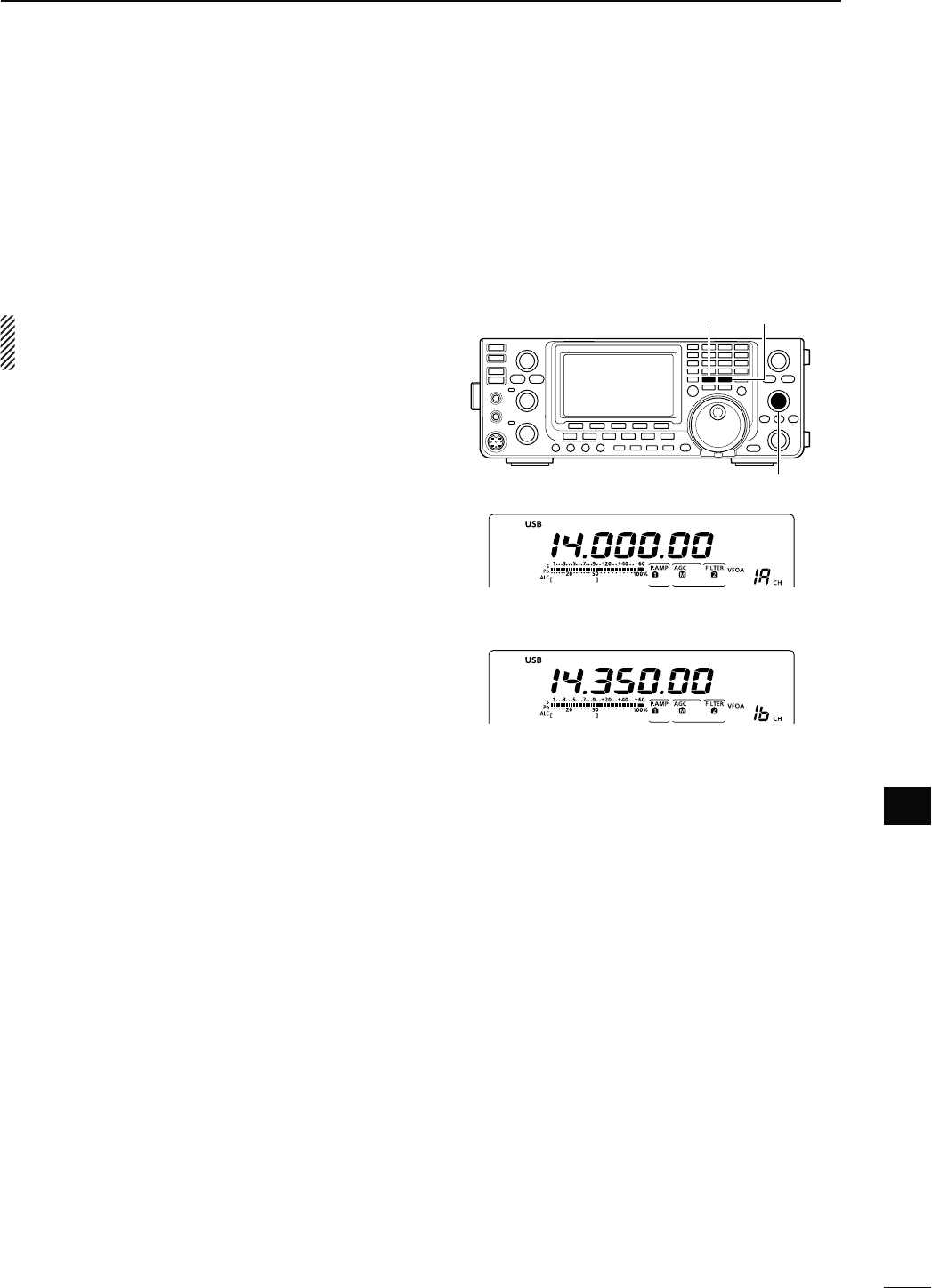
148
11
SCANS
11
N3CANEDGESPROGRAMMING
Memory channels 1A–3A and 1b–3b are the Program
Scan Edge channels. They are used to program the
upper and lower frequency edges for programmed
scans. (p. 149)
Each frequency band has its own Scan Edge chan-
nels. Factory default frequency and operating modes
are programmed into the Scan Edge channels.
If both upper and lower band edges are programmed
with the same frequency, a programmed scan can-
not start.
EXAMPLE: Programming 14.00000 MHz into 1A and
14.35000 MHz into 1b.
q Push [VFO/MEMO] to select the VFO mode.
w Rotate [M-CH] to select scan edge 1A.
e Set 14.00000 MHz as the lower frequency.
r Hold down [MW] for 1 second to program
14.00000 MHz into scan edge 1A.
s4HREEBEEPS SOUND WHEN THEPROGRAMMING ISCOM-
plete.
t Rotate [M-CH] to select scan edge 1b.
y Set 14.35000 MHz as the upper frequency.
u Hold down [MW] for 1 second to program
14.35000 MHz into scan edge 1b.
s4HREEBEEPS SOUND WHEN THEPROGRAMMING ISCOM-
plete.
i If 1A/1b is selected as the scanning range when a
programmed scan is started, it will search for sig-
nals between 14.00000 MHz and 14.35000 MHz.
(p. 149)
[VFO/MEMO] [MW]
[M-CH]
Programming 14.00000 MHz into 1A
Programming 14.35000 MHz into 1b
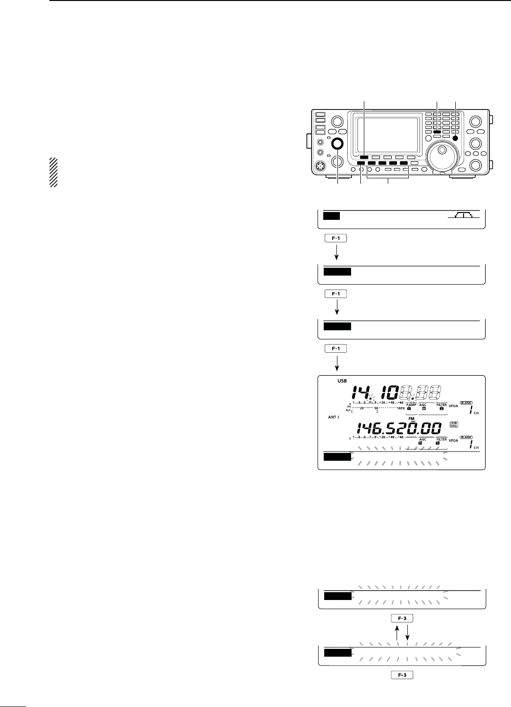
149
11 SCANS
A programmed scan searches for signals between
Program Scan Edge channels “1A–3A” and “1b–3b.”
Before starting the programmed scan, scan edges
must be programmed into these channels.
See the previous page for scan edge programming.
If the same frequencies are programmed into the
Program Scan Edge channels, the programmed
scan will not start.
q Push [VFO/MEMO] to select the VFO mode.
w Push the mode switch to select the desired operat-
ing mode.
s4HEOPERATINGMODECANALSOBECHANGEDWHILESCAN-
ning.
e Push [TS] one or more times to select a tuning step.
(p. 38)
s4HETUNINGSTEPCANALSOBECHANGEDWHILESCANNING
r
P
ush [MENU] one or more times to display the “M2”
screen (Menu 2).
t
P
ush [SCAN](F-1) to display the “SCAN” screen.
y Set [RF/SQL] open or closed.
s4HESCANPERFORMANCEDIFFERSDEPENDINGONTHESQUELCH
setting when the scan was started. See page 146 for
details.
s)FTHE;2&31,=CONTROLFUNCTIONISSETTOh!54/vTHE
SQUELCHIS ALWAYSOPENINTHE 33"#7 AND 2449
modes. (pp. 44, 162)
u Hold down [PRO](F-1) for 1 second to select the
desired scan range between “P1,” “P2” and “P3.”
s4HESCANSEARCHESBETWEENPROGRAMMEDSCANCHAN-
nels 1A–1b (P1), 2A–2b (P2) or 3A–3b (P3).
i Push [PRO](F-1) to start the programmed scan.
s4HE-(ZANDK(ZDECIMALPOINTSANDTHESELECTEDSCAN
range display blink while scanning.
s)F
“Up/Down” is selected as
the “MAIN DIAL (SCAN)”
option
in the Scan Set mode, rotating [MAIN DIAL]
changes the scanning direction. (p. 147)
o When the scan detects a signal, the scan stops,
pauses or ignores it, depending on the Scan Re-
sume function, the VSC function or the squelch sta-
tus.
!0 Push [PRO](F-1) to cancel the scan.
N0ROGRAMMEDSCAN&INEPROGRAMMEDSCAN6&/MODE
D!BOUTTHE&INEPROGRAMMEDSCAN
When a signal is received during Fine programmed
scan, the scanning tuning step is temporarily set to
10 Hz and the scan speed decreases.
q Start the programmed scan.
s&OLLOWSTEPSq through i as described above.
w While scanning, push [FIN](F-3) to switch the scan
function between a programmed scan and a Fine
programmed scan.
e Push [PRO](F-1) to cancel the scan.
[SCAN]/[PRO] [VFO/MEMO] [TS]
[MENU][RF/SQL] Mode switches
PRO ∂FSPAN S E TFIN
SCAN
PROG SCAN:P2
SCAN ME M S WR TCON VS C
M2
PRO FSPAN S E TFIN
SCAN
PROG:P1
F
:
10k
PRO FSPAN S E TFIN
SCAN
PROG:P2
F
:
10k
Hold down
While Programmed scanning
PRO ∂FSPAN S E TFIN
SCAN
PROG SCAN:P2
PRO ∂FSPAN S E TFIN
SCAN
F−PROG SCAN:P2
While Fine programmed scanning
Push
Push
Push
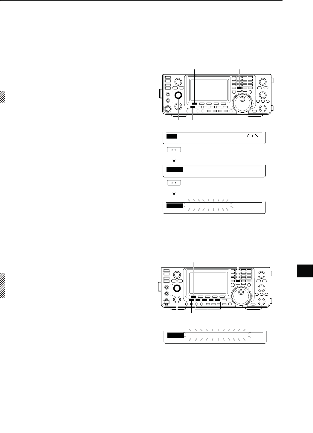
150
11
SCANS
11
D-EMORYSCAN
A Memory scan searches for signals through Memory
channels 1 to 99.
Blank (unprogrammed) Memory channels are skipped.
NOTE: For a Memory scan to start, two or more
Memory channels must be programmed. (p. 140)
q Push [VFO/MEMO] to select the memory mode.
w
P
ush [MENU] to display the “M2” screen (Menu 2).
e
P
ush [SCAN](F-1) to display the “SCAN” screen.
r Set [RF/SQL] open or closed.
s4HESCANPERFORMANCEDIFFERSDEPENDINGONTHESQUELCH
setting when the scan was started. See page 146 for
details.
s)FTHE;2&31,=CONTROLFUNCTIONISSETTOh!54/vTHE
SQUELCHIS ALWAYSOPENINTHE 33"#7 AND 2449
modes. (pp. 44, 162)
t Push [MEM](F-1) to start the Memory scan.
s4HE-(ZANDK(ZDECIMALPOINTSANDh-%-/3#!.v
blink while scanning.
s)F
“Up/Down” is selected as
the “MAIN DIAL (SCAN)”
option
in the Scan Set mode, rotating [MAIN DIAL]
changes the scanning direction. (p. 147)
y Push [MEM](F-1) to cancel the scan.
N-EMORYSCAN-EMORYMODE
[SCAN]/[MEM] [VFO/MEMO]
[MENU][RF/SQL]
SCAN ME M S WR TCON VS C
M2
MEM FSPAN S E TSEL
SCAN
F
:
10k
MEM ∂FSPAN S E TSEL
SCAN
MEMO SCAN
While Memory scanning
D-ODE3ELECTSCAN
Repeatedly scans all Memory channels with the same
operating mode as the displayed mode.
NOTE: For a Mode Select scan to start, two or more
Memory channels must be programmed, and their
operating mode must be the same as the displayed
mode.
q Follow steps q through r as described above.
w Hold down [MEM](F-1) for 1 second to turn ON the
Mode Select scan.
sh-/$%3vAPPEARS
e Push the mode switch to select the desired operat-
ing mode to be scanned.
r Push [MEM](F-1) to start the Mode Select scan.
s4HE-(Z AND K(ZDECIMAL POINTSANDh-/$%3%,
SCAN” blink while scanning.
s)F
“Up/Down” is selected as
the “MAIN DIAL (SCAN)”
option
in the Scan Set mode, rotating [MAIN DIAL]
changes the scanning direction. (p. 147)
s-EMORYSCANAND-ODE3ELECTSCANCANBESWITCHED
by holding down [MEM](F-1) for 1 second.
t Push [MEM](F-1) to cancel the scan.
While Mode Select scanning
Push
Push
MEM ∂FSPAN S E TSEL
SCAN
MODE−SEL SCAN
[SCAN]/[MEM] [VFO/MEMO]
[MENU][RF/SQL] Mode switches
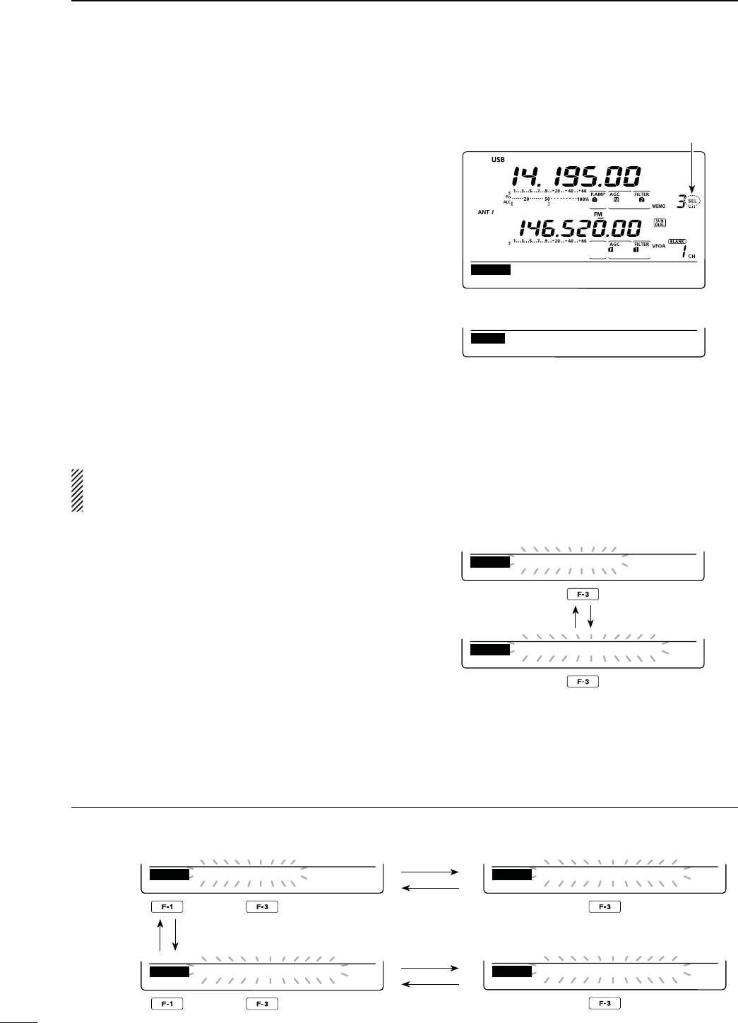
151
11 SCANS
!BOUTTHESCANTYPESWITCHINGPROCEDURE
9OUCANSWITCHTHESCANTYPEBETWEENVARIOUSSCANSWHILESCANNINGASSHOWNBELOW
MEM ∂FSPAN S E TSEL
SCAN
SEL−MEMO SCAN
Select Memory scan
MEM ∂FSPAN S E TSEL
SCAN
SEL−MEMO SCAN
Select Memory scan
D3ELECT-EMORYSCAN
Select Memory scan searches for signals through
Memory channels specified as “Sel” (Select).
NOTE: For a Select Memory scan to start, two or
more Memory channels must be designated as Se-
lect Memory channels. (See above)
q Follow steps q through t as described in ‘D
Memory scan’ on the previous page, to start Mem-
ory scan.
s7HILESCANNINGHOLDINGDOWN;-%-=&FORSECOND
turns ON the Mode Select scan.
w Push [SEL](F-3) to turn ON the Select Memory
scan.
s4HESCANCHANGESTOA3ELECT-EMORYSCAN
sh3%,n-%-/3#!.vBLINKSWHILESCANNING
s0USHING;3%,=&TOGGLESBETWEEN-EMORYSCANOR
Mode Select scan)* and Select Memory scan.
*Only when the Mode Select scan is turned ON.
s)F
“Up/Down” is selected as
the “MAIN DIAL (SCAN)”
option
in the Scan Set mode, rotating [MAIN DIAL]
changes the scanning direction. (p. 147)
e Push [MEM](F-1) to cancel the scan.
All Memory channels can be set as Select Memory
channels, except for the Scan Edge and Call channels.
± When the “SCAN” screen is displayed, push [SEL]
(F-3), or when the “MEM” screen (Memory Menu)
is displayed, push [SEL](F-5) to set or cancel the
displayed Memory channel as a Select Memory
channel.
sh3%,vAPPEARS WHENTHECHANNEL IS SET AS A3ELECT
Memory channel.
s!N ERROR BEEP SOUNDS WHEN THE DISPLAYED -EMORY
channel is a blank channel.
s(OLDINGDOWN[SEL](F-3) or [SEL](F-5) for 1 second
DISPLAYSh3%,!,,#LEARv(OLDDOWN;9%3=&TO
clear all Select Memory channel settings.
MEM ∂FSPAN S E TSEL
SCAN
MEMO SCAN
MEM ∂FSPAN S E TSEL
SCAN
SEL−MEMO SCAN
EDT ( ) SEL
MEM
14.19500 USB
MEM FSPAN S E TSEL
SCAN
F
:
10k
Appears
“SCAN” screen
“MEM” screen (Memory Menu)
While Select Memory scanning
N Memory scan (Memory mode) (Continued)
D 3ETTING#ANCELLING3ELECT-EMORYCHANNELS
Push
[SEL](F-3)
Push
MEM ∂FSPAN S E TSEL
SCAN
MEMO SCAN
MEM ∂FSPAN S E TSEL
SCAN
MODE−SEL SCAN
Hold down
[MEM](F-1)
Memory scan
Mode Select scan
Push
[SEL](F-3)
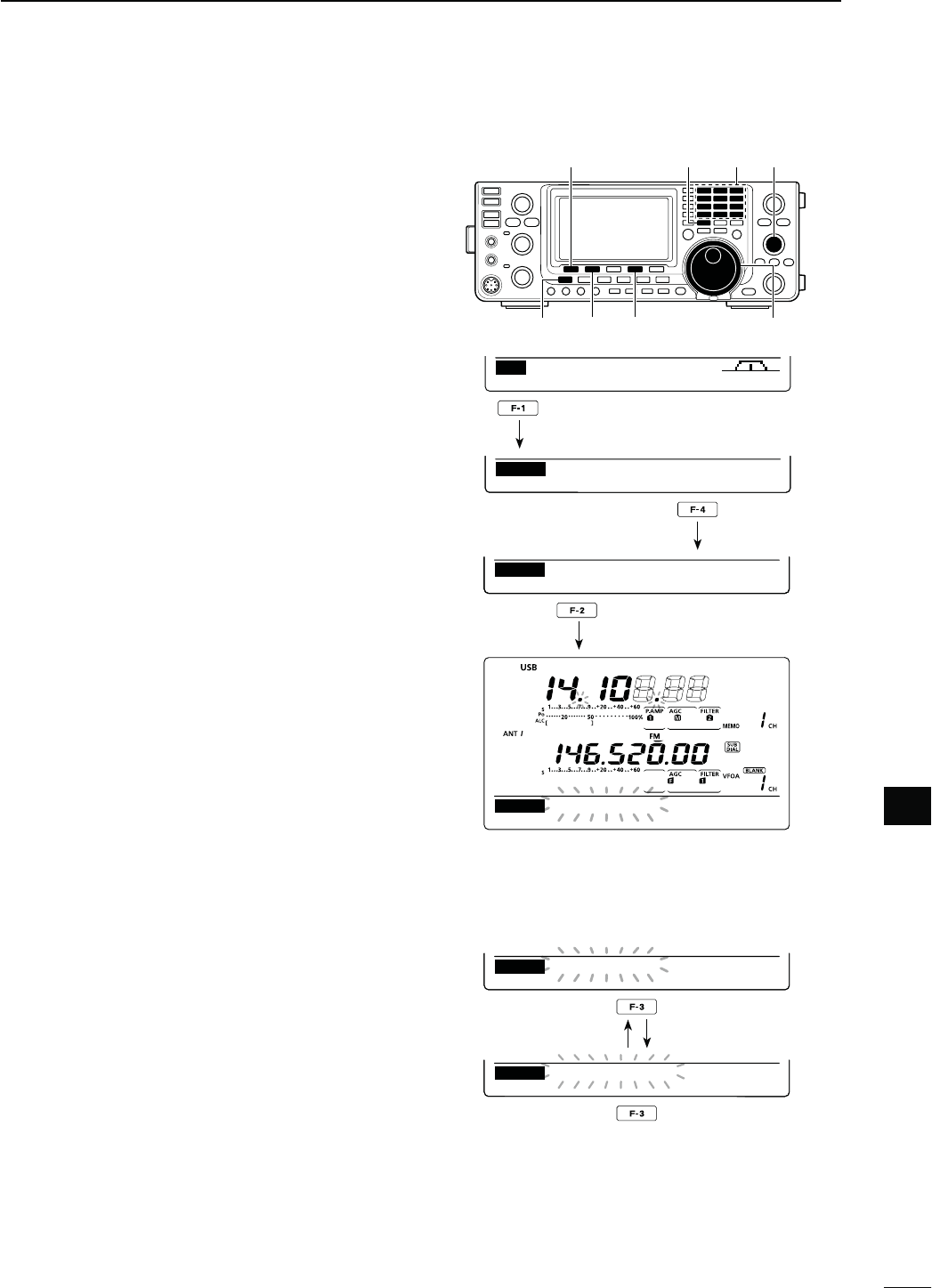
152
11
SCANS
11
∂F (Delta Frequency) scan searches for signals within
the specified range with the displayed VFO frequency
or Memory channel frequency as the center frequency.
The frequency range is specified by the width of the
selected span.
q Push [VFO/MEMO] once or twice to select the VFO
mode or memory mode.
w
P
ush [MENU] one or more times to display the “M2”
screen (Menu 2).
e
P
ush [SCAN](F-1) to display the “SCAN” screen.
r Set [RF/SQL] open or closed.
s4HESCANPERFORMANCEDIFFERSDEPENDINGONTHESQUELCH
setting when the scan was started. See page 146 for
details.
s)FTHE;2&31,=CONTROLFUNCTIONISSETTOh!54/vTHE
SQUELCHIS ALWAYSOPENINTHE 33"#7 AND 2449
modes. (pp. 44, 162)
t Push [SPAN](F-4) one or more times to select the
desired ∂F span width.
sÒ K(Z Ò K(Z Ò K(Z Ò K(Z Ò K(Z
±500 kHz and ±1 MHz are selectable.
y Set the center frequency of the ∂F scan.
s)NTHE6&/ MODEPUSHTHE KEYPADORROTATE;-!).
DIAL] to set the center frequency.
s)NTHEMEMORYMODEROTATE;-#(=TOSELECTTHEDE-
sired Memory channel whose frequency will be the cen-
ter frequency.
u Push [∂F](F-2) to start the ∂F scan.
sh∂F SCAN,” the MHz and kHz decimal points blink while
scanning.
s)F
“Up/Down” is selected as
the “MAIN DIAL (SCAN)”
option
in the Scan Set mode, rotating [MAIN DIAL]
changes the scanning direction. (p. 147)
i When the scan detects a signal, the scan stops,
pauses or ignores it, depending on the Scan Re-
sume function, VSC function or the squelch status.
o Push [∂F](F-2) again to cancel the ∂F scan.
N ∂&SCANAND&INE∂&SCAN
D!BOUTTHE&INE∂&SCAN
When a signal is received during Fine ∂F scan, the
scanning tuning step is temporarily set to 10 Hz and
the scan speed decreases.
q Start ∂F scan.
s&OLLOWSTEPSq through u as described above.
w While scanning, push [FIN](F-3) to switch the scan
function between ∂F scan and Fine ∂F scan.
e Push [∂F](F-2) to cancel the scan.
[SCAN] [VFO/MEMO] [M-CH]
[MENU] [∂F] [SPAN] [MAIN DIAL]
SCAN ME M S WR TCON VS C
M2
MEM FSPAN S E TSEL
SCAN
F
:
10k
MEM FSPAN S E TFIN
SCAN
F
SCAN
20k
MEM FSPAN S E TSEL
SCAN
F
:
20k
F
While ∂F scanning
Keypad
MEM FSPAN S E TFIN
SCAN
MEM FSPAN S E TFIN
SCAN
F−
F
SCAN
F
SCAN
20k
20k
While Fine ∂F scanning
Push
Push
Push
Push
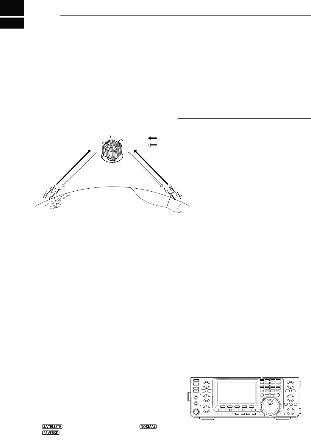
12
153
SATELLITE OPERATION
Both Satellite Mode B (435 MHz uplink, 145 MHz
downlink) and Mode J (145 MHz uplink, 435 MHz
downlink) can be operated with the IC-9100, and
Mode L can be operated when the optional UX-9100
1200 MHz BAND UNIT is installed.
Satellite communications is possible only when a sat-
ellite is in view and its transponder is operating.
N3ATELLITENOTES
1. NEVER set the output power too high. Too much
power will shorten the satellite’s life.
Set your transmit power so that your downlink sig-
nal level is lower than the beacon’s signal level.
2. Confirm a satellite’s operating mode in advance
through documentation (magazines, etc.) or via ap-
propriate satellite tracking software. In the wrong
mode, you cannot use the satellite, even if you re-
ceive its beacon signal.
3. Preamplifiers may be necessary to receive satel-
lite signals. Optional amplifiers, AG-25, AG-35 and
AG-1200* (for the UX-9100), can be used with the
IC-9100. (p. 71)
* AG-1200 has been discontinued, but it can be still be
used.
4. When you use a reverse tracking satellite in the
SSB mode, use LSB for the uplink frequency and
USB for the downlink frequency.
s7HENUSINGANORMALTRACKINGSATELLITEIN33"MODE
use USB for both the uplink and downlink frequencies.
Operating frequencies in the satellite mode can be se-
lected either before or after selecting the mode. Nor-
mal and reverse tracking are selectable.
D4RANSFERRINGTHE6&/FREQUENCIESTOTHE
SATELLITE6&/
q Select the downlink frequency (receive) in the MAIN
band, and the uplink frequency (transmit) in the
SUB band.
w
Hold down [SATELLITE] for 1 second to transfer the
frequencies, selected in step q, to the satellite VFO.
s4HESATELLITEMODEISAUTOMATICALLYSELECTEDAFTERTRANS-
ferring.
s
“” and the last operated tracking icon (“ ” or
“”) appear.
s6&/OR-EMORYMODEDATAISDISPLAYEDONTHE35"
band during satellite mode.
435 MHz
band
435 MHz
band
145 MHz band
145 MHz
band
FUJI 3 (FO-29)
Uplink
Downlink
-ODE*OPERATINGDIAGRAM
;%XAMPLE=&5*)&/-ODE*
Uplink frequency : 145.9000–146.0000 MHz
Downlink frequency : 435.8000–435.9000 MHz
Tracking direction : Reverse
CW beacon frequency : 435.7950 MHz
/RBITINFORMATION
Orbit information describes satellite location, reach-
ing angles, etc. This information may be available in
ham magazines or organization publications, such
as those from ARRL, RSGB handbook, etc.
Satellite tracking software is also convenient.
N3ATELLITECOMMUNICATIONSOUTLINE
N3ELECTINGTHESATELLITEMODE
[SATELLITE]
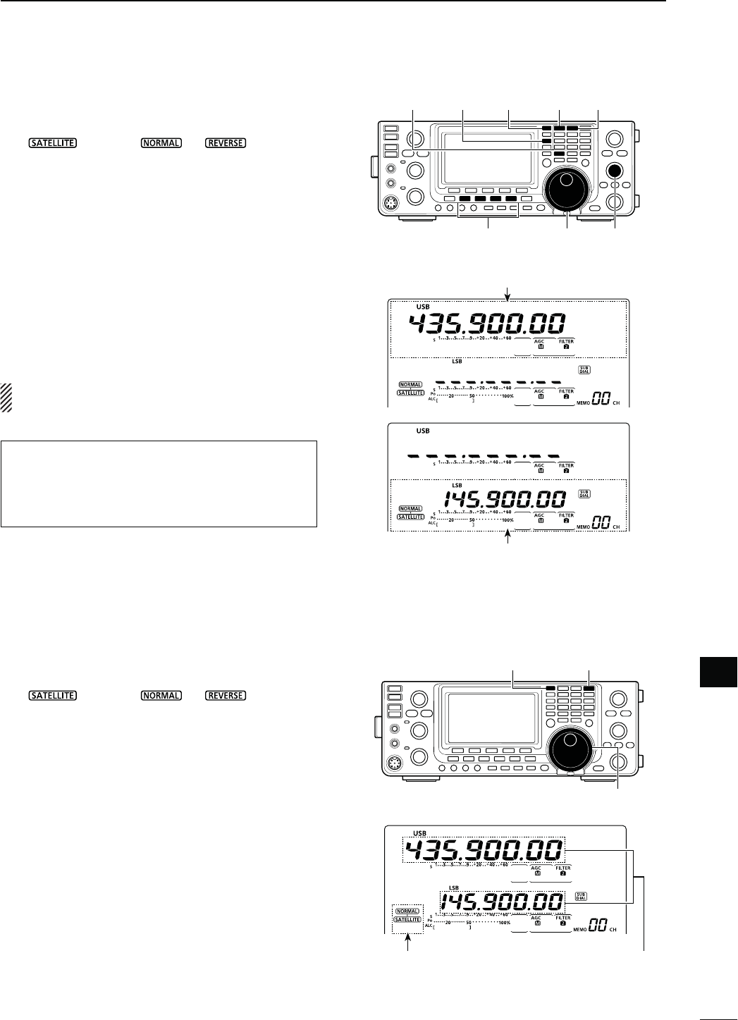
154
12
SATELLITE OPERATION
12
N3ETTINGTHESATELLITE6&/
q Push [SATELLITE] to enter the satellite mode.
s
“ ” and either “ ” or “ ” appear.
w Push [VFO/MEMO] to toggle between the satellite
VFO and Memory mode.
s6&/OR-EMORYMODEDATAISDISPLAYEDONTHE35"
band while in the satellite mode.
e Push [MAIN](1.8 1) to enable downlink frequency
tuning.
s4HEUPLINKFREQUENCYDISAPPEARS
r Select the downlink frequency and the operating
mode.
s0USH;-!).=AGAINAFTERTUNING
t Push [SUB](3.5 2) to enable uplink frequency tun-
ing.
s4HEDOWNLINKFREQUENCYDISAPPEARS
s0USH;35"=AGAINAFTERTUNING
NOTE: To select the operating mode for uplink, push
[SUB] to enable the SUB band setting mode.
N4RACKINGSELECTION
q Push [SATELLITE] to enter the satellite mode.
s
“ ” and either “ ” or “ ” appears.
w Push [NOR/REV](7 3) to toggle between normal
and reverse tracking.
D.ORMALTRACKING
Both downlink and uplink frequencies simultaneously
increase or decrease in the same steps when you ro-
tate the [MAIN DIAL].
D2EVERSETRACKING
The downlink frequency follows the tuning dial rota-
tion, however, the uplink frequency changes in the
reverse direction to the [MAIN DIAL] rotation, in the
same steps.
[SATELLITE] [SUB] [VFO/MEMO]
[MAIN]
(1.8 1)
[SUB]
(3.5 2)
[MAIN DIAL] [M-CH]Mode switch
MAIN Band
Downlink (Receive) frequency
SUB Band
Uplink (Transmit) frequency
[SATELLITE]
[NOR/REV]
(7 3)
[MAIN DIAL]
Varies simultaneously
Satellite and
tracking icon
In the DR mode, pushing [SATELLITE] cancels it, and
then switches the transceiver to the satellite mode.
If you want to operate in the DR mode after exiting
THESATELLITEMODEYOUMUSTHOLDDOWN;$6s$2=FOR
1 second.
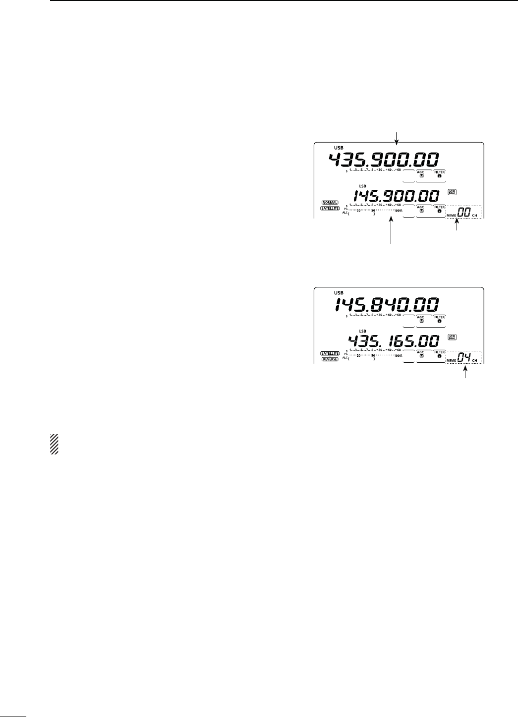
155
12 SATELLITE OPERATION
N3ATELLITEMEMORY
The IC-9100 has 20 satellite memory channels (CH 00
to 19) to memorize both uplink and downlink frequen-
cies, operating modes and other data.
D3ATELLITEMEMORYSELECTION
q Push [SATELLITE] to enter the satellite mode.
w Push [VFO/MEMO] to select the satellite memory
mode.
sh-%-/vANDTHEMEMORYCHANNELNUMBERAREDISPLAYED
beside the uplink frequency (SUB band) display.
e Rotate [M-CH] to select a satellite mode Memory
channel.
D3ATELLITEMEMORYPROGRAMMING
q Push [SATELLITE] to enter the satellite mode.
w Push [VFO/MEMO] to select the satellite memory
mode.
e Rotate [M-CH] to select the desired Memory chan-
nel.
r Select the desired downlink frequency in the MAIN
band, and uplink frequency in the SUB band, as
well as the operating mode.
t Hold down [MW] for 1 second to program the con-
tents into the Memory channel.
s4HREEBEEPSSOUNDWHENTHEmemory programming has
completed.
NOTE: Tracking selection, normal or reverse, is not
programmed in the satellite memory channels.
Satellite memory channel
Select the desired satellite
memory channel
Downlink (Receive) frequency
Uplink (Transmit) frequency
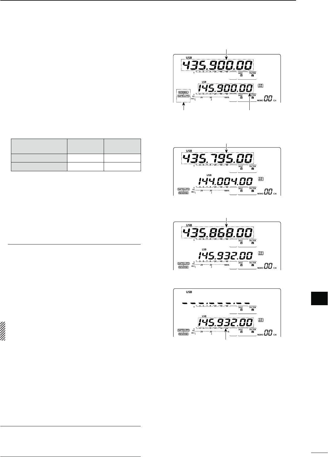
156
12
SATELLITE OPERATION
12
N0REPARATION
q Decide on a usable satellite, and point your antenna
direction towards it.
w Confirm the approximate location of the satellite
and operating mode (e.g. “B,” “J,” etc.) through a
publication (magazine, etc.) or an appropriate sat-
ellite tracking software.
e Push [SATELLITE] to enter the satellite mode.
r Push [NOR/REV](7 3) to toggle between normal
and reverse tracking.
t Select the operating mode as listed below.
s4OSELECTTHEOPERATINGMODEFORTHEUPLINKPUSH;35"=
before selecting the operating mode.
Satellite Downlink
(MAIN band)
Uplink
(SUB band)
Reverse tracking type USB (or CW) LSB (or CW)
Normal tracking type USB (or CW) LSB (or CW)
y Select the desired downlink frequency in the MAIN
band to match the beacon frequency.
s2EFERTOAHAMMAGAZINEORBOOKFORDETAILEDINFORMA-
tion.
s!DJUSTTHEANTENNADIRECTIONSOTHATTHE3METERSHOWS
its strongest level.
s4HE3METERLEVELSHOULDBENOTEDTOADJUSTTRANSMIT
power during a loop test.
u Perform a loop test.
,OOPTESTPROCEDURES
q Rotate [MAIN DIAL] to select a vacant frequency,
within the satellite’s coverage, as the downlink
frequency on the MAIN band.
w Push [PTT] on the microphone to transmit. (or
[TRANSMIT] on the transceiver)
e
Push [SUB](3.5 2), then select the uplink fre-
quency on the SUB band while transmitting a
single tone such as a whistle to find your down-
link signal and monitor your own signal correctly.
r Push [SUB](3.5 2) again after setting.
NOTE: To avoid excessive power, set the output
power so that the downlink signal strength is lower
than the beacon’s strength.
i Select the desired frequency to begin your satellite
communications.
s"OTHTHEDOWNLINKANDUPLINKFREQUENCIESCHANGESIMUL-
taneously.
o When your downlink audio drifts (Doppler effect),
push [SUB](3.5 2) then rotate [MAIN DIAL] to adjust
the uplink frequency (SUB band).
After adjusting, push [SUB](3.5 2) again.
s7HENAPARTICULARSTATIONSAUDIOISOFFFREQUENCYUSE
the RIT function (push [RIT]).
!0 To exit the satellite operation, push [SATELLITE].
For your convenience
As the transceiver has 20 satellite memory channels,
once entered, desired satellite frequencies can be
recalled instantly.
Satellite and
tracking icon
Uplink (transmit) frequency
Downlink (receive) frequency
Select the downlink frequency to match with
the beacon frequency.
Select a vacant frequency as the downlink fre-
quency, within the satellite’s coverage.
Adjust the uplink frequency

157
12 SATELLITE OPERATION
N3ATELLITEOPERATION
When your own signal can be received with a loop
test, satellite communication can be performed.
q When a frequency is shifted by the Doppler effect,
push [SUB](3.5 2), then rotate [MAIN DIAL] to re-
tune the uplink frequency.
s4HEDOWNLINKFREQUENCYDISPLAYDISAPPEARS
w When the other station’s signal frequency is shifted,
push [MAIN](1.8 1), then rotate [MAIN DIAL] to re-
tune the downlink frequency.
s4HEUPLINKFREQUENCYDISPLAYDISAPPEARS
s9OUCANTUNETHEDOWNLINKFREQUENCYÒK(ZWITHTHE
RIT. (p. 69)
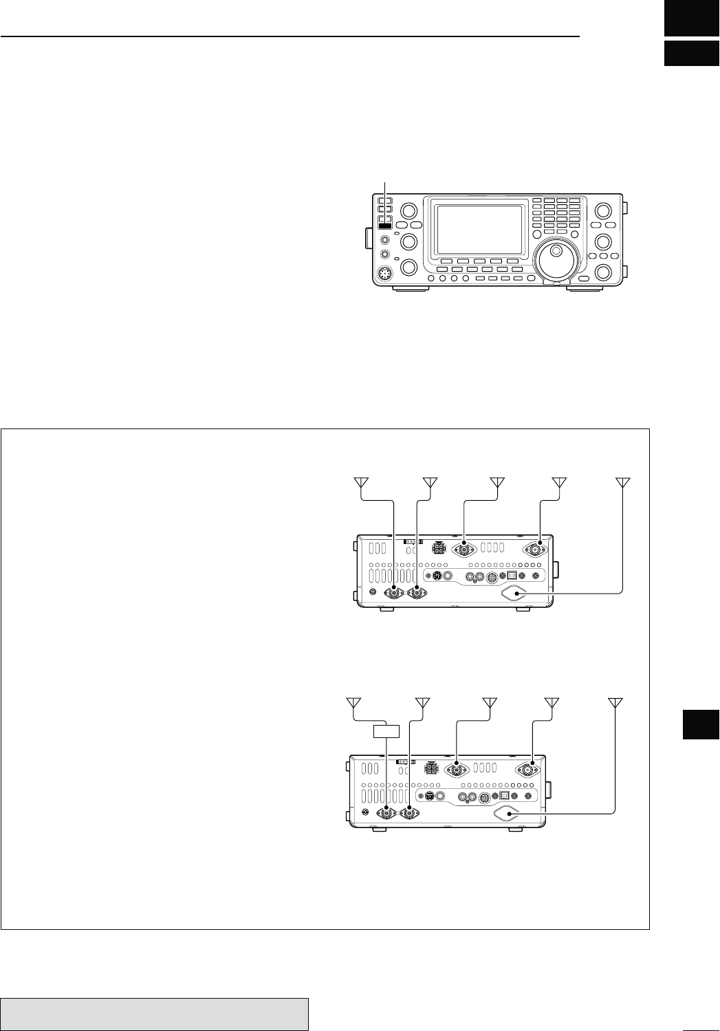
13
158
ANTENNA TUNER OPERATION
13
The IC-9100 has 2 antenna connectors for the HF/50
MHz bands, [ANT1] and [ANT2], and a dedicated an-
tenna connector for each of the 144 MHz, 430 MHz
AND-(ZBANDSATOTALOFANTENNACONNEC-
tors.
9OU CAN MEMORIZETHEANTENNA FOREACH OPERATING
band the IC-9100 covers.
When you change the operating band to one outside of
the current memorized antenna band, the antenna is
automatically selected for the new band. (See below)
This function is especially convenient when you use 2
antennas for HF and 50 MHz band operation.
To use the band memory, select “Auto” as the “[ANT]
Switch” option in the Set mode. (p. 163)
s!NTENNASELECTIONMODEh!UTOv (default)
Once an antenna has been selected for use with a
BANDBYPUSHING;!.4s-%4%2=THEANTENNAISAUTO-
matically selected whenever that band is accessed.
[EXAMPLE]: a 3.5/7 MHz antenna is connected to
[ANT1], a 21/28/50 MHz antenna is connected to
[ANT2]. When the antenna selector function is set to
“Auto,” the correct antenna is automatically selected
when you changes bands.
s!NTENNASELECTIONMODEh-ANUALv
;!.4s-%4%2=FUNCTIONSHOWEVERTHEBANDMEMORY
function is disabled. In this case, you must select an
antenna manually.
s4HEANTENNACONNECTORSFORTHE-(Z-(ZAND
1200 MHz* bands are automatically selected.
[EXAMPLE]: an optional antenna tuner and HF an-
tenna are connected to [ANT1] and a 50 MHz an-
tenna is connected to [ANT2].
s!NTENNASELECTIONMODEh/&&v
;!.4s-%4%2=DOESNOTFUNCTION4HE;!.4=CONNEC-
tor is always selected during HF and 50 MHz bands
operation.
N!NTENNACONNECTIONANDSELECTION
3.5/7 MHz
bands
21/28/50 MHz
bands
144 MHz
band
430 MHz
band
1200 MHz
band*
[ANT2] [144MHz ANT] [430MHz ANT]
[1200MHz ANT]
[ANT1]
[ANT2] [144MHz ANT] [430MHz ANT]
[1200MHz ANT]
[ANT1]
AH-4
HF
bands
50 MHz
bands
144 MHz
band
430 MHz
band
1200 MHz
band*
* The optional UX-9100 is required for 1200 MHz frequency
band operation.
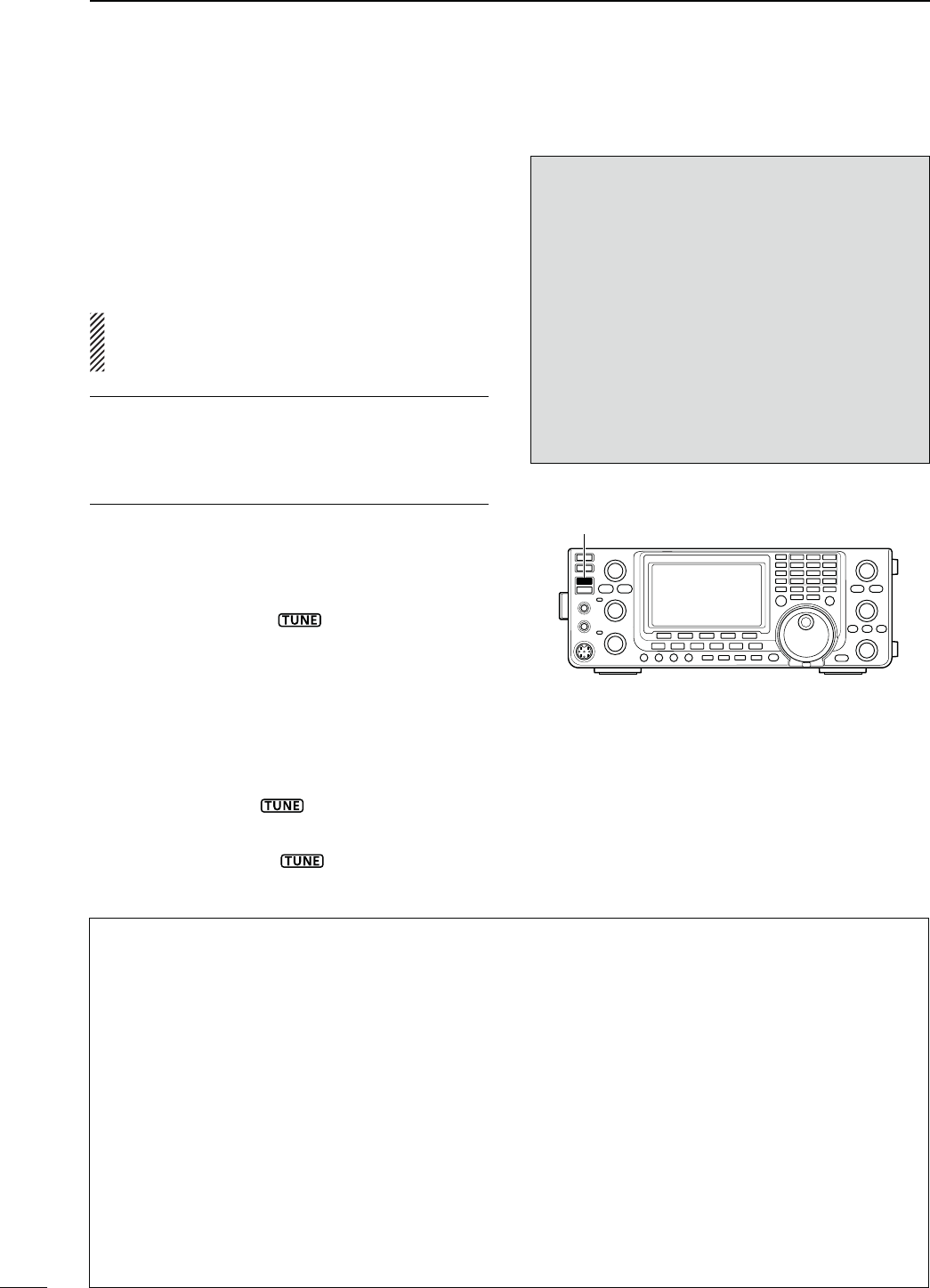
159
13 ANTENNA TUNER OPERATION
M )FTHETUNERCANNOTTUNETHEANTENNACHECKTHE
FOLLOWINGANDTRYAGAIN
sTHECORRECTANTENNACONNECTORSELECTION
sTHEANTENNACONNECTIONANDFEEDLINE
sTHEUNTUNEDANTENNA372,ESSTHANFORTHE
(&BANDS,ESSTHANFORTHE-(ZBAND
sTHETRANSMITPOWER7FORTHE(&BANDS7FOR
the 50 MHz band)
sTHEPOWERSOURCEVOLTAGECURRENTCAPACITY
If the tuner still cannot reduce the SWR to less than
1.5:1 after checking the above, perform the following:
sTRYMANUALTUNINGONEORMORETIMES
sADJUSTTHEANTENNAFEEDLINELENGTH4HISISEFFECTIVE
for higher frequencies in some cases.)
Even if manual tuning does not match the antenna and
the tuner turns OFF the first time, it may match the an-
tenna the second time.
M4UNINGANARROWBANDWIDTHANTENNA
Some antennas, especially for the low bands, have
a narrow bandwidth. These antennas may not be
tuned beyond the edge of their operating bandwidth,
therefore, manually tune such an antenna as follows:
;%XAMPLE= Suppose you have an antenna which has
an SWR of 1.5:1 at 3.55 MHz and an
SWR of 3:1 at 3.8 MHz.
q Select 3.55 MHz and hold down [TUNER] for 1
second. to start manual tuning.
w Select 3.80 MHz and hold down [TUNER] for 1
second to start manual tuning.
NOTES:
s4HEINTERNALANTENNATUNERCANONLYTUNETHE(&
and 50 MHz bands— the 144 MHz, 430 MHz and
1200 MHz* bands cannot be tuned.
sNEVER transmit without an antenna properly con-
nected to each antenna port in use.
s7HENANTENNASARECONNECTED SELECTTHEAN-
TENNATOBEUSEDWITH;!.4s-%4%2=
s)FTHE372ISHIGHERTHANABOUTWHENTUN-
ing farther than 100 kHz from an antenna’s pro-
grammed preset point, hold down [TUNER] for
1 second to start manual tuning.
s4HEINTERNALTUNERMAYNOTBEABLETOTUNEINthe
AM mode. In such cases, hold down [TUNER] for
1 second to manually tune.
[TUNER]
N!NTENNATUNEROPERATION
The internal automatic antenna tuner automatically
matches the transceiver to the selected antenna. After
the tuner matches an antenna, the variable capacitor set-
tings are memorized as a preset point for each frequency
range (100 kHz steps). Therefore, when you change the
frequency range, the variable capacitors are automati-
cally preset to the memorized setting.
CAUTION: NEVER transmit with the tuner ON when
no antenna is connected. This will damage the trans-
ceiver. Be careful of the antenna selection.
For your convenience
When you purchase a brand-new antenna, or you
want to change the antenna settings, you can erase all
of the internal antenna tuner preset points with “Tuner
Preset Clear” in the Set mode. (p. 163)
D 4UNEROPERATION
± Push [TUNER] to turn ON the internal antenna
tuner. The antenna is automatically tuned when the
antenna SWR is higher than 1.5:1.
s7HENTHETUNERIS/.h ” appears.
D-ANUALTUNING
Transmitting in SSB with a soft voice, the internal tuner
may not automatically tune correctly. In such cases,
manual tuning is helpful.
± Hold down [TUNER] for 1 second to start manual
tuning.
s!SIDETONESOUNDSh ” blinks and the TX/RX indi-
cator (MAIN Band) lights red while tuning.
s)FTHETUNERCANNOTREDUCETHE372TOLESSTHAN
after 20 sec. of tuning, “ ” disappears and the TX/
RX indicator (MAIN Band) goes out.
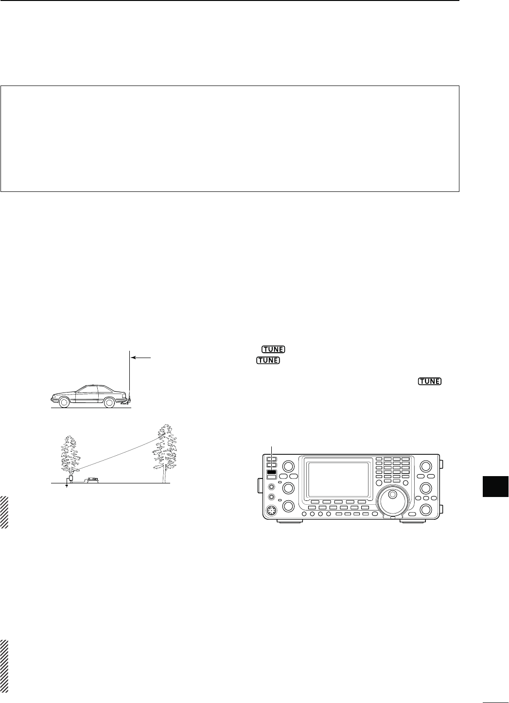
160
13
ANTENNA TUNER OPERATION
13
s!((&-(Z!54/-!4)#!.4%..!45.%2
The optional AH-4 matches the IC-9100 to a long
wire antenna more than 7 m/23 ft long (3.5 MHz and
above).
s3EEPAGEFORTHETRANSCEIVERAND!( CONNEC-
tion.
s3EETHE!(INSTRUCTIONMANUALINSTALLATIONANDAN-
tenna connection details.
AH-4 setting example:
For mobile operation
For outdoor operation
Long wire
Optional AH-2b
antenna element
R DANGER HIGH VOLTAGE!
NEVER touch the antenna element while tuning
or transmitting.
CAUTION: operate the AH-4 without an antenna
wire or element. The tuner and transceiver will be
damaged.
NEVER operate the AH-4 when it is not grounded.
Transmitting before tuning may damage the trans-
ceiver. Note that the AH-4 cannot tune when using a
1⁄2 λ long wire or multiple of the operating frequency.
When connecting the AH-4, the antenna connector
assignments are [ANT2] for the internal tuner and
[ANT1] for the AH-4. The antenna icon in the LCD
displays “ANT” when the AH-4 is connected and se-
lected.
s!(OPERATION
Tuning is required for each frequency. Be sure to re-
tune the antenna before transmitting when you change
the frequency— even slightly.
q Select the desired frequency in an HF or 50 MHz
band for use with the AH-4.
s4HE!(WILLNOTOPERATEONFREQUENCIESOUTSIDE
the ham bands.
w Hold down [TUNER] for 1 second.
s
“ ” blinks while tuning.
e “” appears constantly when tuning is com-
plete.
s7HENTHECONNECTEDWIRECANNOTBETUNEDh ” dis-
appears and the AH-4 is bypassed. At that point the an-
tenna wire connection root is to the transceiver directly,
and not via the AH-4 antenna tuner.
r To bypass the AH-4 manually, push [TUNER].
[TUNER]
s!NTENNATUNEROFTHE)#07%52/
When using an external antenna tuner such as the
IC-PW1/EURO’s tuner, tune when the internal tuner is
turned OFF. After tuning has completed, turn ON the
internal tuner.
Otherwise, both tuners simultaneously tune, and
proper tuning may fail.
See the instruction manual included with each antenna
tuner for their respective operations.
N/PTIONALEXTERNALTUNEROPERATION
s!UTOMATICTUNERSTART (HF bands only)
If you want to deactivate the tuner when the VSWR
is 1.5:1 or less, use the auto tuner start function and
turn OFF the tuner. This function activates the tuner
automatically when the SWR is high, and is con-
trolled in the Set mode. (p. 163).
s4HETUNERMAYNOTSTARTIFTHE48POWEROUTPUTISNOTSTA-
ble longer than the specified time period in the SSB or
CW mode operation.
s044TUNERSTART
Tuning of the internal*/external antenna tuner starts
when [PTT] is pushed on a new frequency that is
MORE THAN AWAY FROM THE LASTTUNED FREQUENCY
This function removes the “holding down [TUNER]”
operation, and starts tuning on the first transmission
on a new frequency.
*Tuning starts if the internal antenna tuner is ON.
This function is turned ON in the Set mode. (p. 163).
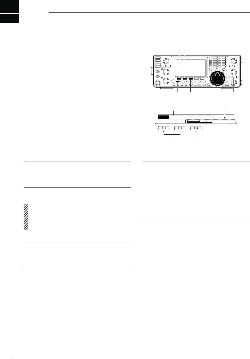
14
161
SET MODE
N3ETMODEDESCRIPTION
The Set mode is used for programming infrequently
changed values or functions.
D 4HE3ETMODESETTINGS
q
Hold down
[MENU] for 1 second to enter the Set
mode.
w Push [Y](F-1) or [Z](F-2) to select the desired
item.
e Rotate [MAIN DIAL] to select the desired option.
s(OLDDOWN;&=FORSECONDTORESETTOTHEDEFAULTSET-
ting, if desired.
r Push [MENU] to save, and exit the Set mode.
Select the item Reset to the default
setting
[]
[MENU] [F-3] [MAIN DIAL]
[][]
Ù
1
Ú50%
SET LCD Contrast
Displays the Set mode
item name and number Displays the option
,#$#ONTRAST1. $EFAULT
!DJUSTTHE,#$CONTRASTTOBETWEENANDIN
STEPS
,#$"ACKLIGHT2. $EFAULT
!DJUSTTHE,#$BACKLIGHTBRIGHTNESSTOBETWEEN
ANDINSTEPS
NOTE: Regardless of this setting, the LCD backlight
BRIGHTNESSISMAXIMUMATPOWER/.BYDE-
sign. (It is not an equipment malfunction.) Then, the
brightness level automatically returns to the ad-
justed value.
"EEP,EVEL3. $EFAULT
Adjust the confirmation and band edge beep tones
OUTPUTLEVELTOBETWEENANDINSTEPS
"EEP,EVEL,IMIT4. $EFAULT/.
Turn the confirmation and band edge beep tones out-
put level limiting ON or OFF.
When you set this item to ON, the beep tones are ad-
justed by the [AF] control until rotating the [AF] control
reaches the level specified in the
“Beep Level” item, as
described above.
Further rotation will not increase the
volume of the beep tones.
s/&&"EEPLEVELADJUSTMENTISNOTLIMITED
s/. "EEPLEVELADJUSTMENTISLIMITEDTOTHELEVEL
specified in “Beep Level,” above.
"EEP5. $EFAULT/.
Turn the confirmation beep ON or OFF.
Set the beep output level in
the “Beep Level” item as
described to the left
.
s/&&4HECONlRMATIONBEEPIS/&&3ILENTOPERA-
tion)
s/. 4HECONFIRMATIONBEEPSOUNDS EACH TIME A
switch is pushed.
"AND%DGE"EEP6. $EFAULT/.$EFAULT
When you tune into or out of an amateur band’s fre-
quency range, you can hear a beep tone.
)FYOUSELECTh/.5SERvORh/.5SER48vYOUCAN
program a total of 30 band edge frequencies in
the
“User band Edge” item.
9OUCANSETTHEBEEPOUTPUTLEVELIN
the “Beep Level”
item as described to the left
.
s/&& "ANDEDGEBEEPIS/&&
s/.$EFAULT 7HENYOUTUNEINTOOROUTOFTHE
default amateur band’s frequency
range, a beep sounds.
s/.5SER 7HENYOUTUNEINTOOROUTOFAUSER
programmed amateur band’s fre-
quency range, a beep sounds.
s/.5SER487HENYOUTUNEINTOOROUTOFAUSER
programmed amateur band’s fre-
quency range, a beep sounds.
In addition, transmission is inhibited
outside the programmed range.

162
14
SET MODE
14
5SER"AND%DGE7.
This “User Band Edge” item appears only when “ON
5SERvORh5SER/.48vISSELECTEDINTHEh"AND
Edge Beep” item. (p. 161)
7HENYOUSELECTh/.5SERvORh/.5SER48vIN
the “Band Edge Beep” item, you can program a total
of 30 band edge frequencies in this item. See page 42
for programming details.
"EEP3OUND-!).8. $EFAULT(Z
Set a desired beep frequency for the MAIN Band to
between 500 Hz and 2000 Hz in 10 Hz steps.
9OUCANSETTHEBEEPOUTPUTLEVELIN
the “Beep Level”
item
. (p. 161)
"EEP3OUND35"9. $EFAULT(Z
Set a desired beep frequency for the SUB Band to be-
tween 500 Hz and 2000 Hz in 10 Hz steps.
9OUCANSETTHEBEEPOUTPUTLEVELIN
the “Beep Level”
item
. (p. 161)
2&31,#ONTROL10. $EFAULT2&31,
Set the [RF/SQL] control operation.
s!54/ ;2&31,= FUNCTIONS AS ONLY AN 2&
GAINCONTROLIN33"#7AND2449A
squelch control in AM, FM and DV.
s31, ;2&31,=FUNCTIONs as a squelch con-
trol.
s2&31, ;2&31,=FUNCTIONs as a noise squelch
or an 3METERSQUELCHIN&-ONLYas
an S-meter squelch in SSB, CW, 2449,
AM and DV.
-ETER0EAK(OLD11. $EFAULT/.
Turn the Meter Peak Hold function ON or OFF.
When this function is set to ON, the peak level of a re-
ceived signal strength or the output power is displayed
for approximately 0.5 seconds.
&-$6#ENTER%RROR12. $EFAULT/.
Turn the FM and DV center error detection ON or
OFF.
When an off-frequency signal is received, the MAIN
and SUB Band’s TX/RX indicators blink.
4IME/UT4IMER13. $EFAULT/&&
To prevent a prolonged transmission, the transceiver
has a Time-Out Timer function.
If a continuous transmission exceeds the set period,
the transmission will be cut off.
Set the time period to 3, 5, 10, 20 or 30 minutes, or
turn OFF the Time-Out Timer function.
044,OCK14. $EFAULT/&&
Turn the PTT Lock function ON or OFF.
To prevent accidental transmissions, this function in-
hibits transmitting, when turned ON.
1UICK30,)415. $EFAULT/.
Turn the Quick Split function ON or OFF.
When this item is set to ON, hold down [SPLIT] for 1
second to shift the transmit frequency from the receive
frequency, according to the “SPLIT Offset” option as
described below. See page 83 for details.
30,)4/FFSET16. $EFAULT-(Z
Set the offset* for the quick split function.
*The difference between transmit and receive frequencies.
The frequency offset can be set to between –9.999
MHz and +9.999 MHz in 1 kHz steps.
SPLIT LOCK 17. $EFAULT/&&
Turn the Split Lock function ON or OFF.
When this item is set to ON, you can use [MAIN DIAL]
to adjust the transmit frequency while holding down
[XFC], even while the Dial Lock function is enabled.
See pages 82, 83 for split frequency operation de-
tails.

163
14 SET MODE
$50/FFSET18.
3ETTHEOFFSETFORDUPLEXOPERATION9OUCANSETTHE
repeater offset for each band.
*The difference between transmit and receive frequencies.
± When you select this item, hold down [BAND](MAIN/
SUB) for 1 second to select the desired frequency
band. Then, rotate [MAIN DIAL] to set the offset.
s4HEFREQUENCYOFFSETCANBESETTOBETWEEN-(Z
and 9.9999 MHz*.
*99.9999 MHz for the 1200 MHz frequency band.
The default value may differ, depending on the se-
lected frequency band and transceiver version.
NOTE:
s9OUCANUSETHISSETTINGONLYWHENTHE3PLITFUNC-
tion is OFF for the HF/50 MHz frequency band.
shvISDISPLAYEDWHENABLANKMEMORYCHANNEL
is selected, or the satellite mode is ON.
The optional UX-9100 is required for 1200 MHz frequency
band operation.
/NE4OUCH2EPEATER19. $EFAULT$50–
Set the one touch repeater shift direction.
s$50n4HETRANSMITFREQUENCYSHIFTSDOWNFROMTHE
receive frequency by the offset amount.
s$504HETRANSMIT FREQUENCY SHIFTSUPFROMTHE
receive frequency by the offset amount.
!UTO2EPEATER 20.
$EFAULT/.–1 ; for U.S.A. version
ON ; for Korea version
(Only U.S.A. and Korea versions)
Set the Auto Repeater function ON or OFF.
To activate the Auto Repeater function, first program the
auto repeater frequency range, then select ON. (p. 67)
U.S.A. version:
s/.n!CTIVATESDUPLEXONLY
s/.n!CTIVATESDUPLEXANDTONE
s/&& !UTOREPEATERFUNCTIONISTURNED/&&
Korea version:
s/. !CTIVATESDUPLEXANDTONE
s/&& !UTOREPEATERFUNCTIONISTURNED/&&
4UNER!UTO3TART21. $EFAULT/&&
Turn the Automatic Antenna Tuner function ON or
OFF. This function is for only the HF bands.
s/&&4HEINTERNALANTENNATUNERREMAINS/&&EVEN
when the SWR is high.
s/. 4HEINTERNALANTENNATUNERAUTOMATICALLYSTARTS
tuning when the SWR is high, even if the tuner
is turned OFF.
4UNER0443TART22. $EFAULT/&&
Whenever you push [PTT], the internal or external an-
tenna tuner automatically starts tuning if the operat-
INGFREQUENCYHASCHANGEDBYMORETHANFROMTHE
last-tuned frequency.
s/&&4UNINGSTARTSONLYWHEN;45.%2=ISPUSHED
s/. )NTERNALANTENNATUNER4UNINGSTARTSWHEN
you push [PTT] on a new frequency, if the in-
ternal antenna tuner is ON.
(External antenna tuner) Tuning always starts
when you push [PTT] on a new frequency, re-
gardless of whether the external antenna tuner
is ON or OFF.
4UNER0RESET#LEAR23.
Select the desired antenna.
The selected antenna’s preset memory* is cleared by
holding down [CLR](F-4) for 1 second.
* The variable capacitor settings are memorized as a
preset point for each frequency range (100 kHz steps)
after the tuner matches an antenna.
s#,2!.44HEPRESETMEMORYOF;!.4=SANTENNA
is cleared.
s#,2!.44HEPRESETMEMORYOF;!.4=SANTENNA
is cleared.
;!.4=3WITCH24. $EFAULT!UTO
Set the antenna switch function to Auto, Manual or OFF.
When you change the operating frequency on the HF/
50 MHz frequency band, this function will automatically
select the correct antenna, or you must do it manually.
s/&& ;!.4s-%4%2= DOES NOT FUNCTION 4HE
[ANT1] connector is always selected.
s-ANUAL 9OUMUSTMANUALLYCHANGETHEANTENNABY
PUSHING;!.4s-%4%2=
s!UTO 4HEANTENNAMEMORIZEDBYTHEBANDMEM-
ORYISAUTOMATICALLYSELECTED9OUCANALSO
manually change the antenna by pushing
;!.4s-%4%2=
N Set mode description (Continued)

164
14
SET MODE
14
30%%#(,EVEL25. $EFAULT
!DJUSTTHESPEECHAUDIOOUTPUTLEVELTOBETWEEN
NOOUTPUTANDMAXIMUMOUTPUT
30%%#(,ANGUAGE26. $EFAULT%NGLISH
Select English or Japanese as the speech language.
30%%#(3PEED27. $EFAULT()'(
Select HIGH (faster) or LOW (slower) speech speed.
30%%#(3,EVEL28. $EFAULT/.
The signal level announcement with the voice synthe-
sizer can be turned ON or OFF.
s/&&3IGNALLEVELISNOTANNOUNCED/PERATINGFRE-
quency and mode are announced.
s/. 3IGNALLEVELOPERATINGFREQUENCYANDMODE
are announced.
SPEECH [MODE] SW 29. $EFAULT/&&
Turn the Operating Mode Speech function ON or OFF.
When this function is ON, the selected operating mode
is verbally announced when a mode switch is pushed.
s/&&4HEOPERATINGMODE3PEECHFUNCTIONIS/&&
s/. 4HEOPERATINGMODE3PEECHFUNCTIONIS/.
[SPEECH/LOCK] SW 30.
$EFAULT30%%#(,/#+
Select the [SPEECH/LOCK] switch action.
s30%%#(,/#+0USHING THE ;30%%#(,/#+=
switch turns ON the voice synthe-
sizer function.
Holding down the [SPEECH/LOCK]
switch turns the dial lock function
ON or OFF.
s,/#+30%%#(0USHING THE ;30%%#(,/#+=
switch turns the dial lock function
ON or OFF.
Holding down the [SPEECH/LOCK]
switch turns ON the voice synthe-
sizer function.
-EMOPAD.UMBERS31. $EFAULT
Set the number of available memo pads to 5 or 10.
See page 144 for details.
MAIN DIAL Auto TS 32. $EFAULT()'(
Set the Auto Tuning Step function for [MAIN DIAL].
When rapidly rotating [MAIN DIAL], the tuning step au-
tomatically changes as selected.
There are two types of auto tuning steps: LOW (Faster)
and HIGH (Fastest).
s/&& !UTOTUNINGSTEPISTURNED/&&
s,/7 !PPROXIMATELYTIMESFASTER
s()'(!PPROXIMATELYTIMESFASTERWHENTHETUNING
STEPISSETTOK(ZORSMALLERSTEPSAPPROXI-
mately 2 times faster when the tuning step is
set to 5 kHz or larger steps.
-)#5P$OWN3PEED33. $EFAULT()'(
Set the rate at which frequencies are scanned while
holding down the microphone [UP]/[DN] switches.
s,/7,OWSPEEDTUNINGSTEPSSECOND
s()'((IGHSPEEDTUNINGSTEPSSECOND
1UICK2)4#LEAR34. $EFAULT/&&
Select the RIT/∂TX frequency offset clearing opera-
tion with [CLEAR].
s/&&(OLDINGDOWN;#,%!2=FORSECONDCLEARSTHE
RIT and ∂TX frequency offset.
s/. 0USHING;#,%!2=INSTANTLYCLEARSTHE2)4AND
∂TX frequency offset.
!&#,IMIT35. $EFAULT/.
Turn the AFC (Automatic Frequency Control) limit
function ON or OFF.
The AFC function automatically compensates the tun-
ing when a received frequency drifts or goes off fre-
quency.
s/&&4HE!&#FUNCTIONCONTINUESTOTUNEUNTILTHE
displayed frequency changes to reflect the
center of the signal.
s/. 4HE!&#FUNCTIONSTOPSTUNINGWHENTHEFRE-
quency goes off the limited frequency range,
even if received frequency is off frequency.
AFC limit value:
IF Filter width AFC limit value
15 kHz ±10 kHz
10 kHz ±7 kHz
7 kHz ±5 kHz

165
14 SET MODE
;./4#(=3733" 36.
$EFAULT!UTO-ANUAL
Select the Auto, Manual or Auto/Manual notch filter to
be used for SSB mode operation.
s!UTO
Only the Auto notch filter can be used.
s-ANUAL /NLY THE -ANUAL NOTCH FILTER CAN BE
used.
s!UTO-ANUAL"OTHTHE!UTOAND-ANUALNOTCHlLTERS
can be used.
;./4#(=37!- 37.
$EFAULT!UTO-ANUAL
Select the Auto, Manual or Auto/Manual notch filter
used for AM mode operation.
s!UTO
Only the Auto notch filter can be used.
s-ANUAL /NLY THE -ANUAL NOTCH FILTER CAN BE
used.
s!UTO-ANUAL"OTHTHE!UTOAND-ANUALNOTCHlLTERS
can be used.
-.10OPUP-./.38. $EFAULT/.
Turn the manual notch filter width display ON or OFF.
When this item set to ON, and the manual notch filter
is selected with [NOTCH], and the manual notch filter
width appears on the function display.
"70OPUP0"439. $EFAULT/.
Turn the IF filter passband width and shift value dis-
play ON or OFF.
When this item set to ON, and the [TWIN PBT] control
is rotated, the passband width and shifting value ap-
pear on the function display.
"70OPUP&),40. $EFAULT/.
Turn the IF filter passband width and shift value dis-
play ON or OFF.
When this item set to ON, and [FILTER] is pushed,
the passband width and shifting value appear on the
function display.
33"#73YNC4UNING41. $EFAULT/&&
Turn the displayed frequency shift function ON or
OFF.
When this function is turned ON, the audio pitch or
tones of the received signal will remain the same, even
when the operating mode is changed between SSB
and CW.
The amount of frequency shift may differ, depending
on the CW pitch setting.
s/&&4HEDISPLAYEDFREQUENCYDOESNOTSHIFT
s/. 4HEDISPLAYEDFREQUENCYSHIFTSWHENTHEOP-
erating mode is changed between SSB and
CW.
#7.ORMAL3IDE42. $EFAULT,3"
Select the sideband used to receive CW in the CW
normal mode between LSB and USB.
+%9%2ST-ENU43. $EFAULT+%9%22OOT
3ELECT+%9%22OOTOR+%9%23%.$ASTHEMENU
THATAPPEARSlRSTAFTERPUSHING;+%9=&INTHEh-v
screen (Menu 1), when the CW mode is selected.
s+%9%22OOT -EMORYKEYERMENUAPPEARSlRST
s+%9%23%.$+EYER3%.$MENUAPPEARSlRST
'03ST-ENU44. $EFAULT'032OOT
Select GPS-Root or GPS-POS as the menu that ap-
pears first after holding down [CALL/GPS].
s'032OOT '03MENUAPPEARSlRST
s'030/3 0OSITIONMENUAPPEARSlRST
%840!-045. $EFAULT/&&
Switch the preamplifier control ON or OFF. When
using the optional AG-25, ON must be selected. Oth-
erwise, the preamplifier is never enabled.
DO NOT connect any equipment, such as an SWR or
power meter, between the transceiver and preampli-
fier. In such case, the preamplifier may not function
correctly.
%840!-046. $EFAULT/&&
Switch the preamplifier control ON or OFF. When
using the optional AG-35, ON must be selected. Oth-
erwise, the preamplifier is never enabled.
DO NOT connect any equipment, such as an SWR or
power meter, between the transceiver and preampli-
fier. In such case, the preamplifier may not function
correctly.
N Set mode description (Continued)

166
14
SET MODE
14
%840!-047. $EFAULT/&&
Switch the preamplifier control ON or OFF. When
using the optional AG-1200*, ON must be selected.
Otherwise, the preamplifier will not function.
*AG-1200 has been discontinued, but it can be still be used.
DO NOT connect any equipment, such as an SWR or
power meter, between the transceiver and preampli-
fier. In such case, the preamplifier may not function
correctly.
This item appears only when the optional UX-9100 is
installed.
%84303EPARATE48. $EFAULT3EPARATE
Select the audio output method when the optional
external speakers are connected to both [EXT-SP
(MAIN)] and [EXT-SP (SUB)] jacks.
s3EPARATE 4HE -!). AND 35" "AND AUDIO ARE
separately sent to the [EXT-SP (MAIN)]
and [EXT-SP (SUB)] jacks.
s-IX 4HE -!). AND 35" "AND AUDIO ARE
combined and sent to both the [EXT-SP
(MAIN)] and [EXT-SP (SUB)] jacks.
0HONE3EPARATE49. $EFAULT!UTO
Select the audio output method when headphones are
connected to the transceiver.
s3EPARATE 4HE -!). AND 35" "AND AUDIO ARE
separately sent to the right speaker
(MAIN Band) and left speaker (SUB
Band).
s-IX 4HE -!). AND 35" "AND AUDIO ARE
combined, and sent to both the right
and left speakers.
s!UTO 7HENTHE35""ANDISDISPLAYEDTHE
MAIN and SUB Band audio are sepa-
rately sent to the right speaker (MAIN
Band) and left speaker (SUB Band).
When the SUB Band is not displayed,
the MAIN Band audio is sent to both the
left and right speakers.
3UB"AND-UTE4850. $EFAULT/&&
Turn the SUB Band Audio Mute function ON or OFF.
While transmitting, the SUB band audio is muted when
this function is turned ON.
s/&& 4HE35""ANDAUDIOISNOTMUTED
while transmitting.
s/.30/NLY 4HE35""ANDAUDIOSENTTOTHE
speaker, is muted while transmit-
ting.
s/.3053"4HE35""ANDAUDIOSENTTOTHE
speaker and USB port, is muted
while transmitting.
!##!&31,3ELECT51. $EFAULT-!).
Set the [ACC] socket’s pin 12 (AF) and pin 13 (SQLS)
output usage.
s-!).3ENDSTHE-!)."ANDSRECEIVEAUDIOAND
squelch.
s35" 3ENDSTHE35""ANDSRECEIVEAUDIOAND
squelch.
$!4!!&31,3ELECT52. $EFAULT-!).
Set the [DATA2] socket’s pin 4 (DATA), pin 5 (AF) and
pin 6 (SQL) output usage.
s-!).3ENDSTHE-!)."ANDSRECEIVEAUDIOAND
squelch.
s35" 3ENDSTHE35""ANDSRECEIVEAUDIOAND
squelch.
63%.$3ELECT53. $EFAULT/.
Set the [ACC] socket’s pin 7 (VSEND) and pin 3
(HSEND) output usage.
s/&& 63%.$ISNOTUSED
HSEND is used for all bands.
s5(&/NLY 63%.$ISUSEDFORTHE-(ZAND
1200 MHz bands.
HSEND is used for the HF/50 MHz and
144 MHz bands.
s/. 63%.$ IS USED FOR THE -(Z
430 MHz, and 1200 MHz bands.
HSEND is used for the HF/50 MHz
bands.

167
14 SET MODE
%XTERNAL+EYPAD54. $EFAULT/&&
Turn the external keypad ON or OFF for keyer mem-
ory transmission.
See page 26 for the equivalent circuit of an external
keypad and connection.
s/&& 4HEEXTERNALKEYPADDOESNOTFUNC-
tion.
s+%9%23%.$)NTHE#7MODEPUSHINGONEOFEX-
ternal keypad switches transmits the
desired keyer memory contents.
53"!UDIO31,55. $EFAULT/&&/0%.
Select whether or not to output the audio from the
[USB] connector on the rear panel, according to the
squelch state.
The same audio signals are sent from the [USB] con-
nector and the [ACC] sockets.
- The beep tones and the voice synthesizer announce-
ments are not sent.
- The received audio output level cannot be adjusted
with the [AF] control.
s/&&/0%. 4HERECEIVEDAUDIOISALWAYSSENT
regardless of the squelch state.
s/. 4HERECEIVEDAUDIOISSENTWHENTHE
squelch is open.
53"-/$,EVEL56. $EFAULT
Set the input modulation level of the [USB] connector
TOBETWEENANDINSTEPS
BPS-ODE57. $EFAULT/&&
Turn the [DATA2] socket’s 9600 bps data transmission
ON or OFF.
s/&&&ORONLYTHEREGULARAUDIOORSLOWDATATRANS-
mission.
s/. &ORBPSDATATRANSMISSION
DATA OFF MOD 58. $EFAULT-)#!##
Select the desired connector(s) for data modulation
input in the data OFF mode.
s-)# 5SETHESIGNALSFROM;-)#=
s!## 5SETHESIGNALSFROM;!##=PIN
s-)#!## 5SETHESIGNALSFROM;-)#=AND;!##=
(pin 11).
s53" 5SETHESIGNALSFROM;53"=
DATA MOD 59. $EFAULT!##
Select the desired connector(s) for data modulation
input in the data mode.
s-)# 5SETHESIGNALSFROM;-)#=
s!## 5SETHESIGNALSFROM;!##=PIN
s-)#!## 5SETHESIGNALSFROM;-)#=AND;!##=
(pin 11).
s53" 5SETHESIGNALSFROM;53"=
#)6"AUD2ATE60. $EFAULT!UTO
Set the CI-V data transfer rate between 300, 1200,
4800, 9600, 19200 bps and “Auto.”
When “Auto” is selected, the baud rate is automatically
set according to the data rate of the connected con-
troller.
CI-V Address 61. $EFAULT#H
To distinguish equipment, each CI-V transceiver has
its own Icom standard address in hexadecimal code.
The IC-9100’s address is 7Ch.
When 2 or more IC-9100’s are connected to an op-
tional CT-17 CI-V level converter, rotate [MAIN DIAL] to
SELECTADIFFERENTADDRESSFOREACH)#THERANGE
is 01h to DFh.
#)64RANSCEIVE62. $EFAULT/.
Turn the transceive function using the CI-V system ON
or OFF.
When this item is set to ON, changing the frequency,
operating mode, etc. on the IC-9100 automatically
changes those settings on other Icom transceivers or
receivers, and vice versa.
s/&&4RANSCEIVEFUNCTION/&&
s/. 4RANSCEIVEFUNCTION/.
53"$!4!&UNC63. $EFAULT;='03
Two COM port numbers are assigned to the [USB]
connector. One of them is “USB1,” used for cloning
and CI-V operation. The other one is “USB2,” and the
function is selected by this item.
s----- : “USB2” is not used.
s2449 5SEDTOSEND2449DECODEDSIGNALS
s$6DAT 5SEDFORLOWSPEEDDATAINPUTANDOUTPUT
s)FYOUSETTHEFUNCTIONOFTHE;$!4!=JACKTO
“GPS,” and “DATA1 USB2” is selected as
the “GPS Out” item’s option, as described
below, “USB2” will be used for the low-speed
data input and GPS data output.
N Set mode description (Continued)

168
14
SET MODE
14
53"$!4!&UNC64. $EFAULT;'03=
Select the function of the [DATA1] jack.
s----- : The [DATA1] jack is not used.
s2449 5SEDTOSEND2449DECODEDSIGNALS
s$6DAT 5SEDFORLOWSPEEDDATAINPUTANDOUTPUT
s'03 5SEDFORTHE'03RECEIVERCONNECTIONFOR
position data input.
GPS Out 65. $EFAULT/&&
When a GPS receiver is connected to the [DATA1]
jack, the GPS position data is input through the jack.
9OUCANSELECTWHETHERORNOTTOSENDTHEDATAFROM
the COM port (“USB2”).
NOTE:9OUCANUSETHISFUNCTIONONLYWHENh-----”
or “DVdat” is selected as the “USB2/DATA1 Func”
(63) option, and “GPS” is selected as the “USB2/
DATA1 Func” (64) option.
s/&& 4URNSTHEFUNCTION/&&
s$!4! USB2 : Sends the GPS position data from
the COM port (“USB2”).
$6DAT'03/UT"AUD66. $EFAULT
Set the DV or GPS data transfer speed to 4800 or
9600 bps.
2449$ECODE"AUD67. $EFAULT
3ETTHE2449DECODEMONITORSPEEDTO
4800, 9600 or 19200 bps.
#ALIBRATION-ARKER68. $EFAULT/&&
Use as a simple frequency check of the transceiver.
See page 179 for calibration procedure.
NOTE: Turn OFF the calibration marker after check-
ing the frequency of the transceiver.
s/&&#ALIBRATIONMARKER/&&
s/. #ALIBRATIONMARKER/.
REF Adjust 69.
During frequency calibration, set the internal refer-
ENCEFREQUENCYTOBETWEENANDRANGEIN
steps.
NOTE: The default setting is different for each
transceiver.
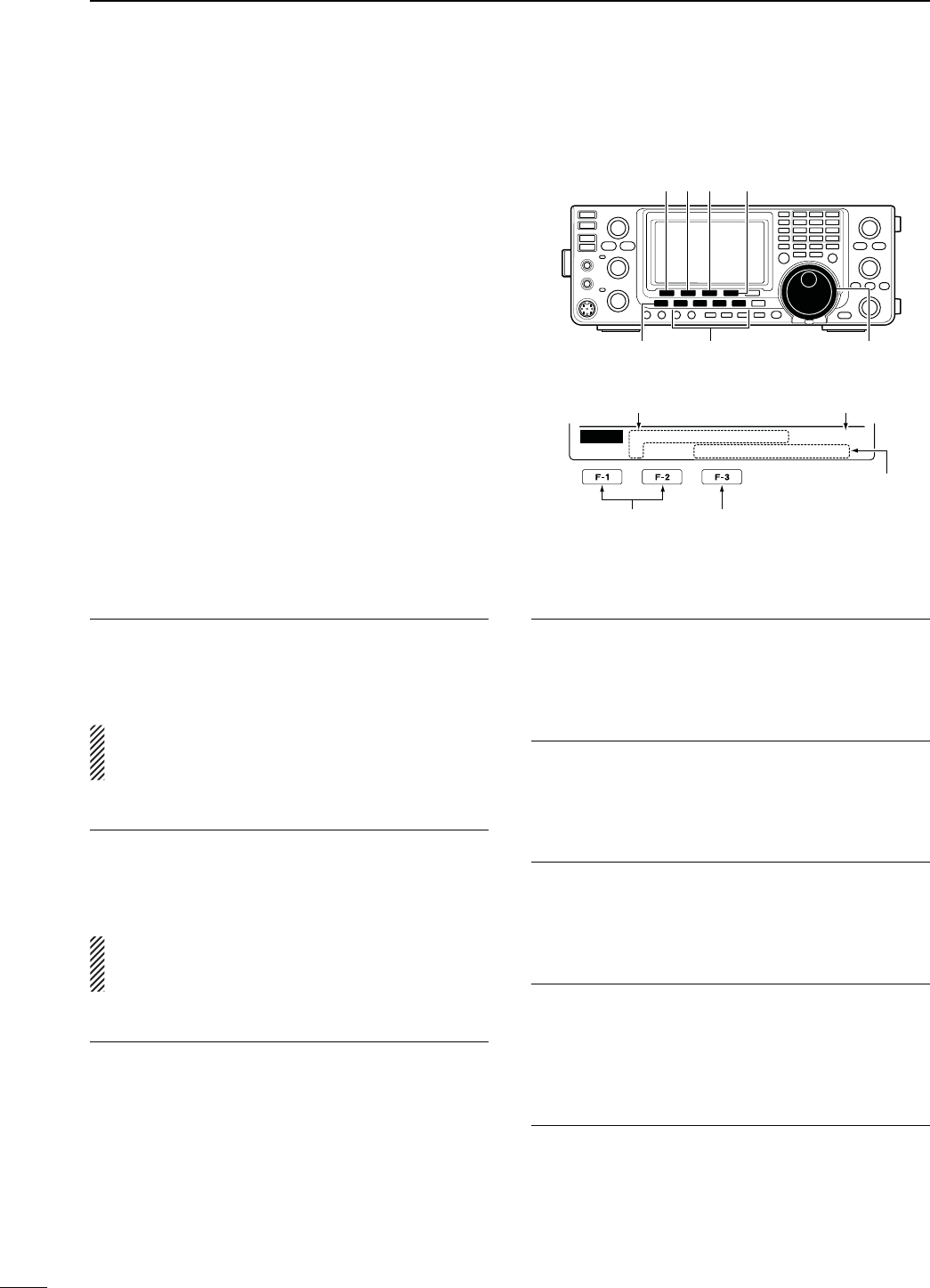
169
14 SET MODE
D The 4ONECONTROL3ETMODESETTINGS
q Push [MENU] one or more times to display the “M2”
screen (Menu 2).
w
Push
[TCON](F-4) to enter the Tone control Set
mode.
e Push a mode switch to select the desired operating
mode.
r Push [Y](F-1) or [Z](F-2) to select the desired
item.
s3ELECTABLEITEMSDIFFERDEPENDINGONTHESELECTEDOPER-
ating mode.
t Rotate [MAIN DIAL] to select the desired option.
s9OUCANSELECTTHEOPTIONFOREACHOPERATINGMODE
s(OLDDOWN;&=FORSECONDTORESETTOTHEDEFAULTSET-
ting, if desired.
y Push [MENU] to save, and exit the Set mode.
Select the item Reset to the default
setting
Mode switches
[]
[MENU]
[F-3] [TCON]
[MAIN DIAL]
[][]
Ù
1
Ú
SSB
[ –
–
–
]
– –
–
–
TCON
RX HPF⁄LPF
Displays the Set mode
item name and number
Displays the option
RX HPF/LPF 1. $EFAULT/&&
-ODE33"#72449!-&-$6
First select the operating mode, then set the receive
audio high-pass filter to between 100 Hz and 2000 Hz
in 100 Hz steps.
NOTE: When the receive audio high-pass and low-
pass filters are active, “RX Bass” and “RX Treble”
items will be reset to the default value.
RX HPF/LPF 2. $EFAULT/&&
-ODE33"#72449!-&-$6
First select the operating mode, then set the receive
audio low-pass filter to between 500 Hz and 2400 Hz
in 100 Hz steps.
NOTE: When the receive audio high-pass and low-
pass filters are active, “RX Bass” and “RX Treble”
items will be reset to the default value.
28"ASS3. $EFAULT
-ODE33"!-&-$6
First select the operating mode, then set the receive
audio bass level to between –5 and +5.
284REBLE4. $EFAULT
-ODE33"!-&-$6
First select the operating mode, then set the receive
audio treble level to between –5 and +5.
48"ASS5. $EFAULT
-ODE33"!-&-$6
First select the operating mode, then set the transmit
audio bass level to between –5 and +5.
484REBLE6. $EFAULT
-ODE33"!-&-$6
First select the operating mode, then set the transmit
audio treble level to between –5 and +5.
4"77)$%,7. $EFAULT
-ODE33"
Set the lower cut-off frequency of the transmission
passband width for your wide setting to 100, 200, 300
or 500 Hz.
4"77)$%(8. $EFAULT
-ODE33"
Set the higher cut-off frequency of the transmission
passband width for your wide setting to 2500, 2700,
2800 or 2900 Hz.
Displays the selected
operating mode
N4ONECONTROL3ETMODEDESCRIPTION
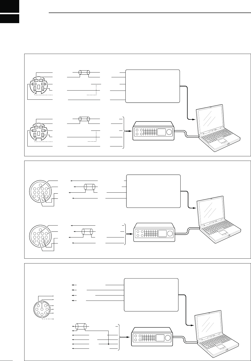
15
171
DATA COMMUNICATION
N#ONNECTIONS
TNC
DATA IN
DATA OUT
(9600bps)
GND
AF OUT
(1200bps)
PTTP
Rear panel view
TX AUDIO
RX AUDIO
PTT
GND
SQ*
q
r
w
t
e
ySQL
DATA IN
DATA OUT
(9600bps)
GND
AF OUT
(1200bps)
PTTP
TX AUDIO
RX AUDIO
PTT
GND
SQ*
q
r
w
t
e
ySQL
PC
RS-232C
TNC
TNC
TNC
PC
RS-232C
Rear panel view
4
8
12
123
765
9
10 11
13
RTTY OUTPUT
AUDIO INPUT
PTT
GND
FSKK
AF OUT
SEND*
GND
4
8
12
123
765
9
10 11
13
RTTY OUTPUT
AUDIO INPUT
PTT
GND
FSKK
AF OUT
SEND*
GND
q
u
i
t
r
y
AFSK OUTPUT
AF INPUT
PTT
GND
SQL INPUT
TNC
AUDIO OUTPUT
AF INPUT
PTT
GND
q
u
i
t
1
2
345
6
7
8
q
u
i
t*
1
y
r*
2
Rear panel view
TNC PC
RS-232C
* When connecting the squelch
line, consult the necessary
manual (TNC, etc.).
s3ELECTPIN63%.$ANDPIN(3%.$OUTPUTUSAGEINTHE3ETMODEP
* e HF/50 MHz : HSEND
u 144/430/1200 MHz : VSEND
*1 When using the VOX function,
no connection is needed.
Refer to the instruction manual
of the external equipment.
*2 When connecting the squelch
line, consult the necessary
manual.
Connect to the serial port,
parallel port, speaker jack,
microphone jack and line IN/
OUT jack, etc.
See the instruction manual
of the application for details.
Connect to the serial port,
parallel port, speaker jack,
microphone jack or line IN/
OUT jack, etc.
See the instruction manual
of the application for details.
Connect to the serial port,
parallel port, speaker jack,
microphone jack and line IN/
OUT jack, etc.
See the instruction manual
of the application for details.
D7HENCONNECTINGTO;$!4!=
D7HENCONNECTINGTO;!##=
D7HENCONNECTINGTO;-)#=
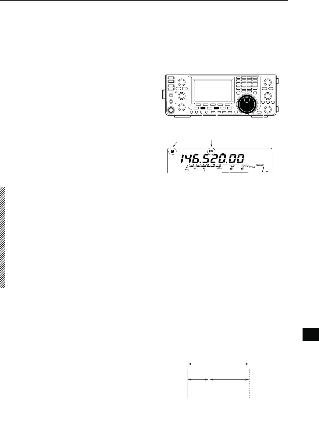
172
15
DATA COMMUNICATION
15
N0ACKET!&3+OPERATION
Before operating packet (AFSK), be sure to consult the
operating manual that came with your TNC.
q Connect the TNC and PC. (p. 171)
w Select the desired band. (p. 35)
e Push [SSB] or [AM/FM] to select the desired oper-
ating mode. (p. 43)
r Hold down the same key you pushed in step e to
select the Data mode.
t Rotate [MAIN DIAL] to select the desired fre-
quency.
y Transmit your AFSK signals using your PC’s key-
board.
s2OTATE;2&0/7%2=TOSETTHEOUTPUTPOWER
s7HILEUSINGA4.#THERELATIVESTRENGTHOFTHETRANSMIT-
ted signal is indicated on the Po meter.
s7HENOPERATINGINTHE33"DATAMODEADJUSTTHEOUT-
put power so that the ALC meter reading stays in the
ALC zone.
NOTE: When connecting the TNC to the ACC socket
on the rear panel, select the USB, LSB, AM and FM
data mode, or disconnect the microphone and ro-
tate [MIC GAIN] fully counterclockwise.
When the SSB data mode is selected, the audio
input from the [MIC] connector is automatically cut,
and the audio input from the [ACC] socket is used.
Also, when the SSB data mode is selected, the fixed
SETTINGSLISTEDBELOWAREAUTOMATICALLYSELECTED
s3PEECHCOMPRESSOR/&&
s4RANSMITBANDWIDTH -)$ Fixed to the default
VALUE(ZTO(Z)
s4XTONE"ASS
s4XTONE4REBLE
s%XAMPLELSB/LSB data mode
Mark freq.: 2125 Hz
Shift freq.: 200 Hz
2325 Hz
200 Hz 2125 Hz
Carrier point
(Displayed frequency)
When operating AFSK in the SSB mode, the displayed
frequency is the signal’s carrier point.
D&REQUENCYDISPLAYDURING!&3+OPERATION
Appears when the FM data mode is selected.
[AM/FM] [MAIN DIAL][SSB]

173
15 DATA COMMUNICATION
When the data transmission speed is set to 9600 bps,
the data signal coming from the TNC is applied exclu-
sively to the internal limiter circuitry to automatically
maintain band width.
NEVER apply data levels from the TNC of over
0.6 Vp-p. Otherwise the transceiver will not be able to
maintain the band width, and your transmitted signal
may possibly interfere with other stations.
D5SINGALEVELMETERORSYNCHROSCOPE
When using a level meter or synchroscope, adjust the
TX audio output level (DATA IN level) from the TNC as
follows.
0.4 Vp-p
(0.2 Vrms) : recommended level
0.2–0.5Vp-p
(0.1–0.25 Vrms) : acceptable level
D.OTUSINGAMEASURINGDEVICE
q Connect the TNC to the transceiver. (p. 171)
w Enter a test mode (“CAL,” etc.) on the TNC, then
transmit some test data.
e If the transceiver fails to transmit the test data, or
transmits sporadically, (TX/RX indicator doesn’t
light or it flashes):
- Decrease the TNC output level until the transmit
indicator lights continuously.
If transmission is not successful, even though the
TX indicator lights continuously:
- Increase the TNC output level.
N!DJUSTINGTHE4.#OUTPUTLEVEL
N$ATATRANSMISSIONSPEED
In the FM data mode, the transceiver can be set to a
maximum data speed of 9600 bps.
q Hold down [MENU] for 1 second to enter the Set
mode.
w Push [Y](F-1) or [Z](F-2) to select “9600bps
Mode.”
e Rotate [MAIN DIAL] to turn the 9600 bps mode ON
or OFF.
s/. BPSDATASPEED
s/&&$ISABLESDATA TRANSMISSION AT BPS
This is used for only regular audio or slower
data transmission.
r Push [MENU] to save and exit the Set mode.
[][]
[MAIN DIAL][MENU]
OFF (default)
Ù
57
ÚOFF
SET 9600bps Mode
INFORMATION!
7HENh2449vISSELECTEDASTHE
“
USB2/DATA1 Func
” (63) item option in
THE3ETMODETHE53"PORTSENDS2449
decode signal. In this case, you must connect a USB cable* between the transceiver’s USB port on the rear panel
and the PC. (p. 167)
*Purchase separately
s4HE53"DRIVERANDTHEINSTALLATIONGUIDECANBEDOWNLOADEDFROMOURWEBSITE
URL: http://www.icom.co.jp/world/index.html).
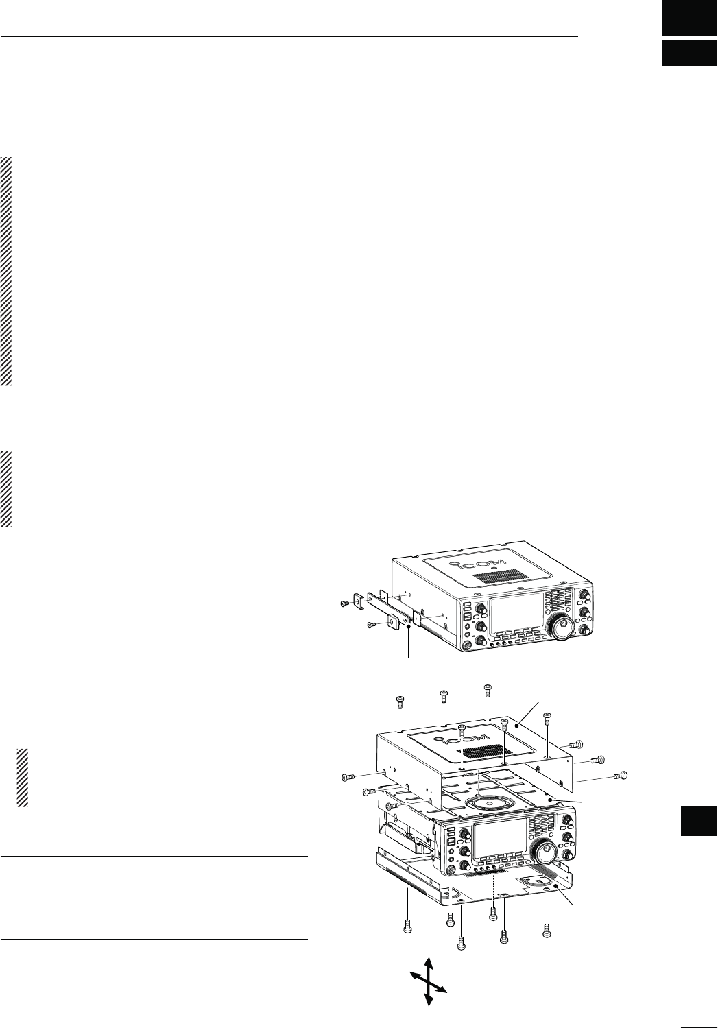
16
174
OPTION INSTALLATION
16
N/PENINGTHETRANSCEIVERSCASE
Icom strongly suggests that the customer have their
dealer or Icom distributor, for a reasonable fee, in-
stall Icom options at the time of the order. Icom un-
derstands that even the simplest of installations de-
mands the judgment of a trained Icom technician.
Therefore, Icom will not be responsible for damage
to the optional unit, or subsequent damage to the
transceiver due to user installation problems. The
option’s or the transceiver’s Warranty can be voided
in such situations, at the sole judgment of Icom.
For those customers who still wish to install their
own options, knowing the risks and possible con-
sequences, the following information is provided for
information purposes only.
The following are instructions for removing the covers
of the IC-9100.
R WARNING!
Turn OFF the power and disconnect
the DC power cable from the transceiver before per-
forming any work on the transceiver. Otherwise,
there is danger of electric shock and/or equipment
damage.
q Remove the two screws from the carrying handle
and remove it from the transceiver.
w Remove the seven screws from the top of the trans-
ceiver and the six screws from the sides, then lift up
the top cover.
e Turn the transceiver upside-down.
#!54)/..%6%2(/,$4(%5.)4"94(%
-!).$)!,/2!.9/4(%2+./"3when you
turn the transceiver upside down. This may dam-
age them, or cause you to drop the transceiver.
r Remove the six screws from the bottom, and then
lift off the bottom cover.
About the leg pads
To detach the leg pads from the right side panel of
the top/bottom cover, push them out from the inside
of each cover, after completing steps q through r
above.
Carrying handle
Bottom cover
Top cover
PA shielding
plate
Top
Bottom
Rear
Front
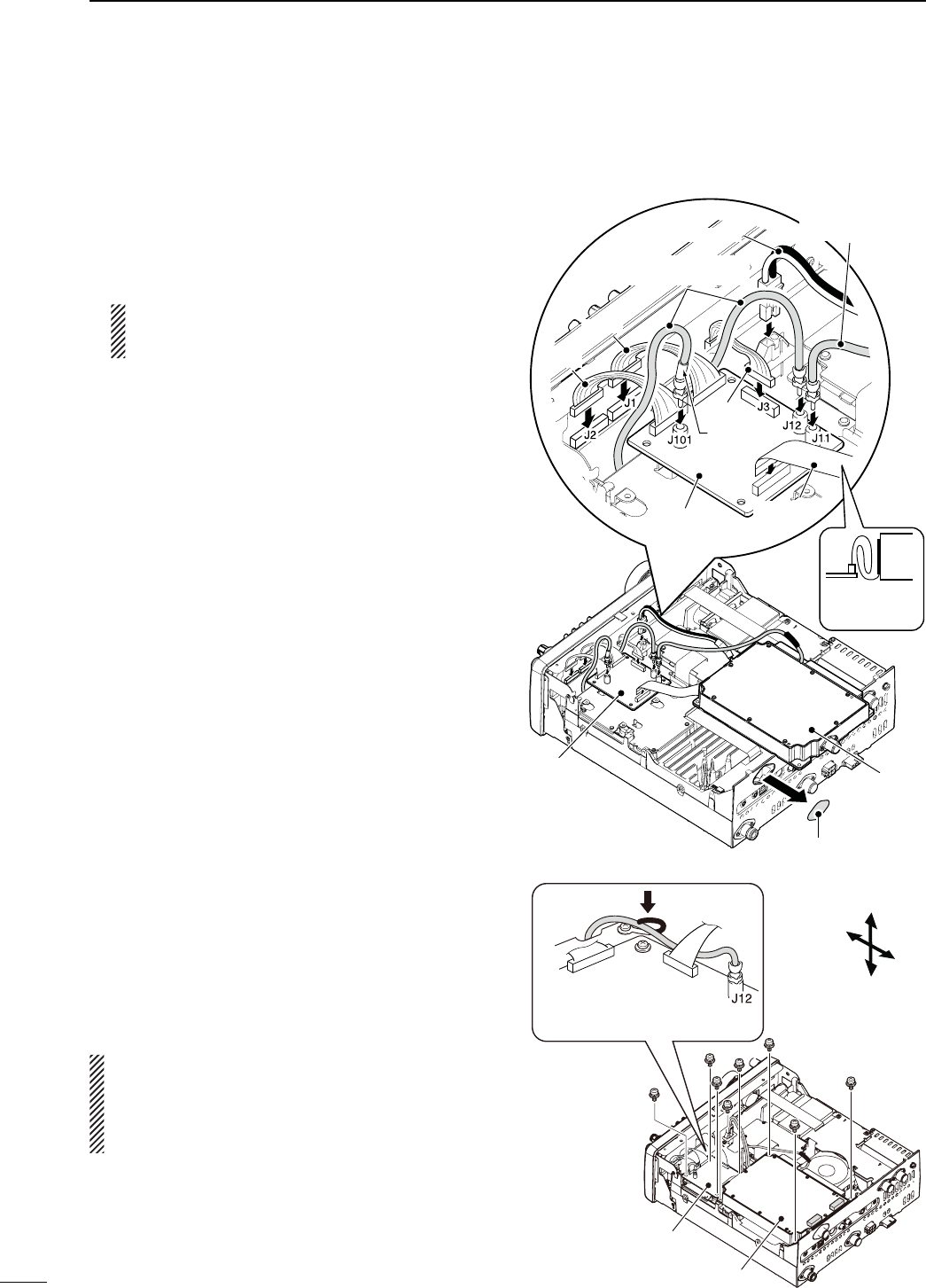
175
16 OPTION INSTALLATION
N UX-9100 1200 MHz BAND UNIT INSTALLATION
The optional UX-9100 is required to operate on the
1200 MHz frequency band.
q Remove the top and bottom covers as shown in the
diagram on page 174.
w Remove the antenna plate from the chassis on the
rear panel using a standard flat screwdriver.
R WARNING!
NEVER push on the antenna plate
using your finger to remove it. This may cause an
injury.
e Connect the DC power cable, coaxial cables and
flat cable, as shown to the right.
± Connect the longer coaxial cable from the trans-
ceiver to J12, and the other one, with a white
mark near the connector, to J101 on the IF unit.
± Connect the coaxial cable from the UX-9100’s
main unit to J11 on the IF unit.
± Ensure the flat cable is connected to the IF unit
correctly, and not upside down.
After connecting, fold the cable, but not too
tightly, as illustrated to the right.
r Connect the 9-pin connector from the transceiver’s
front unit to J3 on the IF unit.
t Connect the 12-pin connector from the IF unit to J1,
and the 11-pin connector to J2 on the transceiver’s
front unit.
y Attach the UX-9100 and IF unit using the eight sup-
plied screws.
s-AKESURETHEmATCABLEISNOTPINCHEDWHENTHE58
9100 is installed.
u Return the top and bottom covers to their original
positions.
R WARNING! When UX-9100 is installed, the unit
continues to draw current, even when the trans-
ceiver is turned OFF. Therefore, when you don’t in-
tend to use the transceiver for a long period of time,
disconnect the transceiver’s DC power cable.
UX-9100
IF unit
Top
Bottom
Rear
Front
IF unit
DC power cable
Coaxial cable
(from the transceiver)
Flat cable
Antenna plate
Coaxial cable
(from the UX-9100)
UX-9100
White mark
11-pin
12-pin
9-pin
IF unit
After connect-
ing, fold the
cable like this.
Secure the coaxial cable, con-
necting to J12 on the IF unit,
by the clip, as shown here.
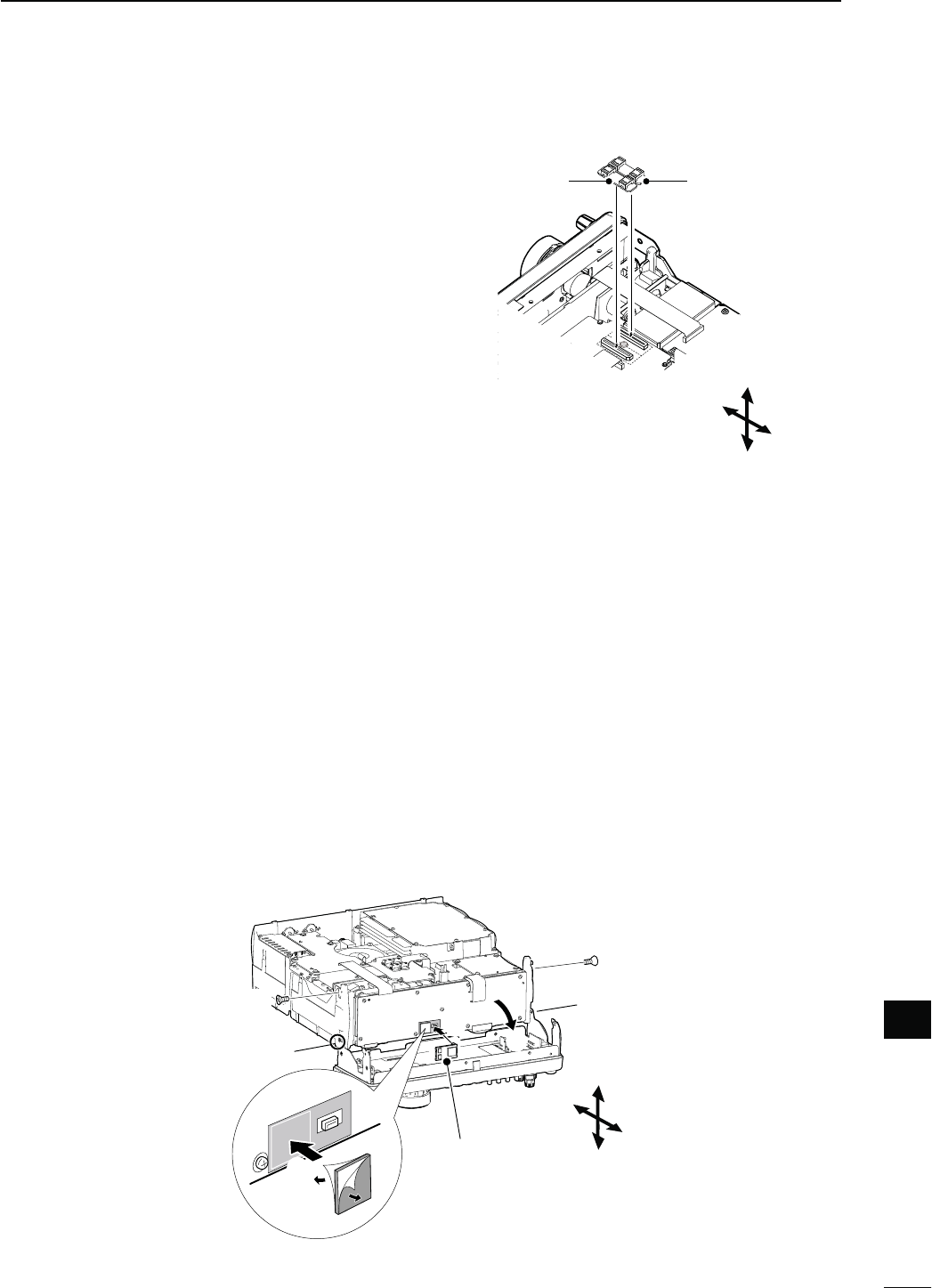
176
16
OPTION INSTALLATION
16
N UT-121 DIGITAL UNIT INSTALLATION
N FL-430/FL-431 1ST IF FILTER INSTALLATION
The optional Roofing Filters, FL-430 1ST IF FILTER
(6 kHz) or FL-431 1ST IF FILTER (3 kHz) provides 6 or 3
kHz filtering to reduce interference from strong nearby
signals.
q Remove the top and bottom covers as shown on
page 174.
w Install the FL-430 or FL-431 as shown to the right.
s4HECONNECTORSONTHE)#AREMARKEDFORTHEAP-
propriate filter.
s%NSURETHE&,OR&,ISINSTALLEDCORRECTLY
e Return the top and bottom covers to the original po-
sitions.
FL-431 (3 kHz)FL-430 (6 kHz)
The optional UT-121 DIGITAL UNIT is required for DV
mode operation, including the DR mode.
q Remove the top and bottom covers as shown on
page 174.
w Remove the upper two screws from the front panel
(q).
e Loosen the lower two screws on the front panel
(w), then slowly fold down the front panel in the
direction of the arrow (e).
r Remove the protective paper from one side of the
double sided adhesive sheet (r), then place the
sheet on the panel, as shown below. (t).
t Remove the other side of the protective paper, and
install the UT-121 as shown below (y).
y Return the front panel, top and bottom covers to
their original positions.
Top
Bottom
Rear
Front
Top
Bottom
Rear
Front
q Remove
UT-121
q Remove
w Loosen
r
w Loosen
t
e
y

17
177
MAINTENANCE
D4RANSCEIVERPOWER
02/",%- 0/33)",%#!53% SOLUTION REF.
Power does not turn ON
when the [POWER] switch is
pushed.
s4HEPOWERCABLEISIMPROPERLYCONNECTED
s!FUSEISBLOWN
s2ECONNECTTHE$#POWERCABLECORRECTLY
s#ORRECT THECAUSETHENREPLACETHEFUSE WITH
an equivalent fuse.
( Fuses are installed in the DC power cable
and in the internal PA unit.)
p. 27
p. 180
D4RANSMITANDRECEIVE
02/",%- 0/33)",%#!53% SOLUTION REF.
No sound from the speaker. s4HEAUDIOVOLUMELEVELISTOOLOW
s4HESQUELCHISCLOSED
s4HETRANSCEIVERISINTRANSMIT
s2OTATE THE ;!&= CONTROL CLOCKWISE TO OBTAIN A
suitable listening level.
s2OTATETHE;2&31,=CONTROLTOOCLOCKPOSI-
tion to open the squelch.
s0USH ;42!.3-)4= TO RECEIVE OR CHECK THE
SEND line of an external unit, if connected.
p. 45
p. 44
p. 46
Sensitivity is too low, and
only strong signals are au-
dible.
s4HEANTENNAISNOTCONNECTEDPROPERLY
s4HEANTENNAFORANOTHERBANDISSELECTED
s4HEANTENNAISNOTPROPERLYTUNED
s4HEATTENUATORISTURNED/.
s2ECONNECTTOTHEANTENNACONNECTOR
s3ELECT AN ANTENNA SUITABLE FOR THE OPERATING
frequency.
s(OLDDOWN;45.%2=FORSECONDTOMANUALLY
tune the antenna.
s0USH;0!-0!44=ONEORMORETIMESTOSELECT
“ATT OFF.”
—
p. 158
p. 159
p. 71
Received audio is unclear or
distorted.
s4HEOPERATINGMODEISNOTMATCHED
s4HE0ASSBAND4UNINGFUNCTIONISTURNED/.
s.OISE "LANKER FUNCTIONS WHEN RECEIVING A
strong signal.
s0reamplifier is turned ON.
s4HE .OISE 2EDUCTION FUNCTION IS TURNED /.
and the [NR] control is too far clockwise.
s3ELECTASUITABLEOPERATINGMODE
s(OLD DOWN ;0"4#,2= FOR SECOND TO RESET
the function.
s0USH;."=TOTURN/&&THEFUNCTION
s0USH ;0!-0!44= ONE OR MORE TIMES TO TURN
OFF the function.
s3ETTHE;.2=CONTROLFORMAXIMUMREADABILITY
p. 43
p. 75
p. 76
p. 71
p. 77
;!.4s-%4%2= DOES NOT
function
s4HE !NTENNA 3WITCH FUNCTION HAS NOT BEEN
turned ON.
s3ET THE !NTENNA 3WITCH FUNCTION TO h!UTOv OR
“Manual” in the Set mode.
p. 163
Transmitting is impossible. s4HE OPERATING FREQUENCY IS OUTSIDE THE SE-
lected ham band.
s3ET THE FREQUENCY TO BE WITHIN THE SELECTED
ham band.
p. 37
Output power is too low. s4HE ;2& 0/7%2= CONTROL IS SET TOO FAR COUN-
terclockwise
s4HE;-)#'!).=CONTROLISSETTOOFARCOUNTER-
clockwise
s4HEANTENNAFORANOTHERBANDISSELECTED
s4HEANTENNAISNOTPROPERLYTUNED
s2OTATETHE;2&0/7%2=CONTROLCLOCKWISE
s3ETTHE;-)#'!).=CONTROLTOASUITABLEPOSI-
tion.
s3ELECT AN ANTENNA SUITABLE FOR THE OPERATING
frequency.
s(OLDDOWN;45.%2=FORSECONDTOMANUALLY
tune the antenna.
p. 46
p. 46
p. 158
p. 159
No contact can be made with
another station.
s4HE2)4OR∂TX function is turned ON.
s4HE 3PLIT FUNCTION ANDOR $UPLEX FUNCTION ARE
turned ON.
s0USH;2)4=OR;∂TX] to turn OFF the function.
s0USH ;30,)4= ANDOR ;$50=& IN THE h-v
screen) to turn OFF the function.
pp. 69, 81
pp. 65, 82
Transmit signal is unclear or
distorted.
s4HE ;-)# '!).= CONTROL IS SET TOO FAR CLOCK-
wise.
s3ETTHE;-)#'!).=CONTROLTOASUITABLEPOSI-
tion.
p. 46
Repeater cannot be ac-
cessed.
s4HESPLITORDUPLEXFUNCTIONISNOTTURNED/.
s4HEPROGRAMMEDSUBAUDIBLETONEFREQUENCYIS
wrong.
s0USH ;30,)4= ANDOR ;$50=& IN THE h-v
screen) to turn ON the function.
s2ESETTHEFREQUENCY
pp. 65, 82
p. 65
AM cannot be selected. s4HE-(ZFREQUENCYBANDISSELECTED s
Select the HF/50/144/430 MHz frequency band.
pp. 43, 61
Transmitting is impossible in
AM.
s4HE
144/430/
1200 MHz frequency band is se-
lected.
s
Select the HF/50 MHz frequency band.
pp. 43, 46
N4ROUBLESHOOTING
The following chart is designed to help you correct
problems which are not equipment malfunctions.
If you are unable to locate the cause of a problem,
or solve it through the use of this chart, contact your
nearest Icom Dealer or Service Center.

178
17
MAINTENANCE
17
D3CANNING
02/",%- 0/33)",%#!53% SOLUTION REF.
Programmed scan does not
stop.
s3QUELCHISOPEN s3ET THE ;2&31,= CONTROL TO THE THRESHOLD
point.
pp. 44,
146
Programmed scan does not
start.
s
The same frequencies have been programmed
into both
“1A–3A” and “1b–3b” of the
scan edge
memory channels.
s0ROGRAMDIFFERENTFREQUENCIESINTOTHE“1A–3A”
and “1b–3b” scan edge memory channels.
p. 148
Memory scan does not start. s OR MORE MEMORY CHANNELS HAVE NOT BEEN
programmed.
s0ROGRAMMORETHANMEMORYCHANNELS p. 140
Select memory scan does
not start.
s OR MORE MEMORY CHANNELS HAVE NOT BEEN
designated as select channels.
s$ESIGNATE MORE THAN MEMORY CHANNELS AS
select channels for the scan.
p. 151
Mode select memory scan
does not start.
sORMOREMEMORYCHANNELSWITHDESIREDMODE
have not been programmed.
s0ROGRAM MORE THAN MEMORY CHANNELS WITH
the desired operating mode.
p. 43
∂F scan does not start. s4HE CENTER FREQUENCY FOR ∂F scan is not pro-
grammed.
s0ROGRAMTHECENTERFREQUENCYFORA∂F scan. p. 152
D$ISPLAY
02/",%- 0/33)",%#!53% SOLUTION REF.
The displayed frequency
does not change properly.
s4HEDIALLOCKFUNCTIONISturned ON.
s4HE3ETMODESCREENISSELECTED
s4HEINTERNAL#05HASMALFUNCTIONED
s(OLD DOWN ;30%%#(,/#+= FOR SECOND TO
turn OFF the function.
s0USH[MENU] to exit the Set Mode.
s2ESETTHE#05
p. 77
p. 161
p. 181
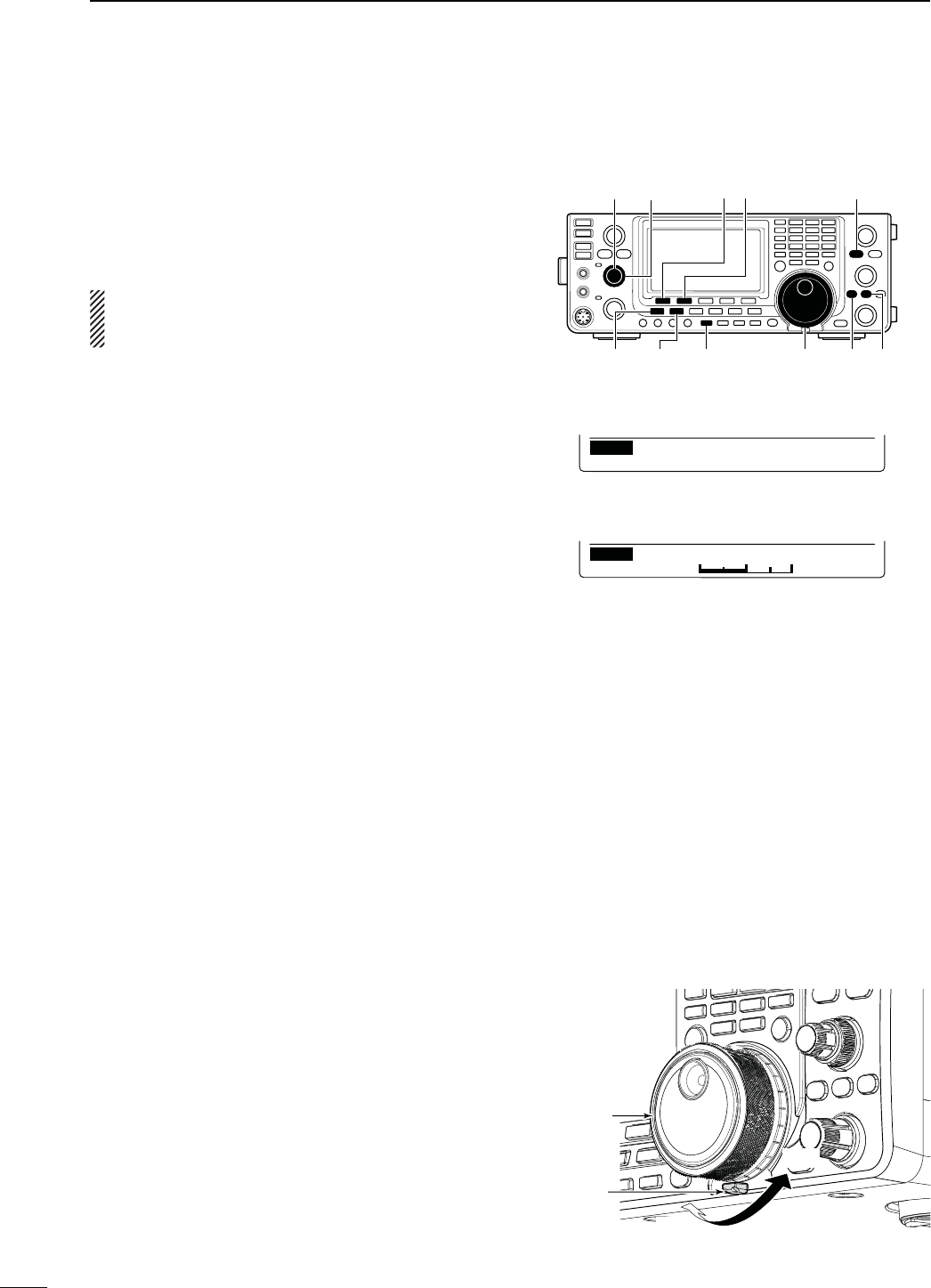
179
17 MAINTENANCE
N&REQUENCYCALIBRATIONAPPROXIMATE
[PBT-CLR]
[]
(MAIN Band)
[]
(MAIN Band)
[][][][]
[][]
[MAIN DIAL]
Ù
68
ÚOFF
SET Calibration Marker
Ù
69
Ú50%
SET REF Adjust
s#ALIBRATIONMARKERITEM
s2%&!DJUSTITEM
A very accurate frequency counter is required to cali-
brate the frequency of the transceiver. However, a
rough check may be performed by receiving radio sta-
tion WWV, WWVH, or other standard frequency sig-
nals.
CAUTION: The IC-9100 has been thoroughly ad-
justed and tested at the factory before being
SHIPPED9OUSHOULDNOTHAVETORECALIBRATEIT
q Push [SSB] to select the USB mode.
w Push [PBT-CLR] for 1 second to clear the PBT set-
tings and make sure that the RIT/∂TX function is
not turned ON.
e Set the frequency to the standard frequency station
minus 1 kHz.
s
When receiving WWV or WWVH (at 15.000.00 MHz) as
a standard frequency, set the operating frequency for
14.999.00 MHz.
s/THERSTANDARDFREQUENCIESCANALSOBEUSED
r Hold down [MENU] for 1 second to enter the Set
mode.
t Push [Y](F-1) or [Z](F-2) to select “Calibration
Marker.”
y Rotate [MAIN DIAL] to turn ON the calibration
marker.
s!SIDETONEMAYBEHEARD
u Push [Z](F-2) to select “REF Adjust.”
i Rotate [MAIN DIAL] to adjust for a zero beat with
the received standard signal.
s:EROBEATMEANSTHATTWOSIGNALSAREEXACTLYTHESAME
frequency, resulting in a single tone being heard.
o Push [Y](F-1) to select “Calibration Marker.”
!0 Rotate [MAIN DIAL] to turn OFF the calibration
marker.
!1 Push [MENU] to save, and exit the Set mode.
The tuning tension of [MAIN DIAL] may be adjusted to
suit your preference.
The tension adjustment is located on the bottom side
of the front panel. See the figure to the right.
Slide the tension adjustment to a comfortable level
while turning the dial continuously and evenly in one
direction. MAIN DIAL
Tuning tension
adjustment
Light
Firm
N-AINDIALTUNINGTENSIONADJUSTMENT
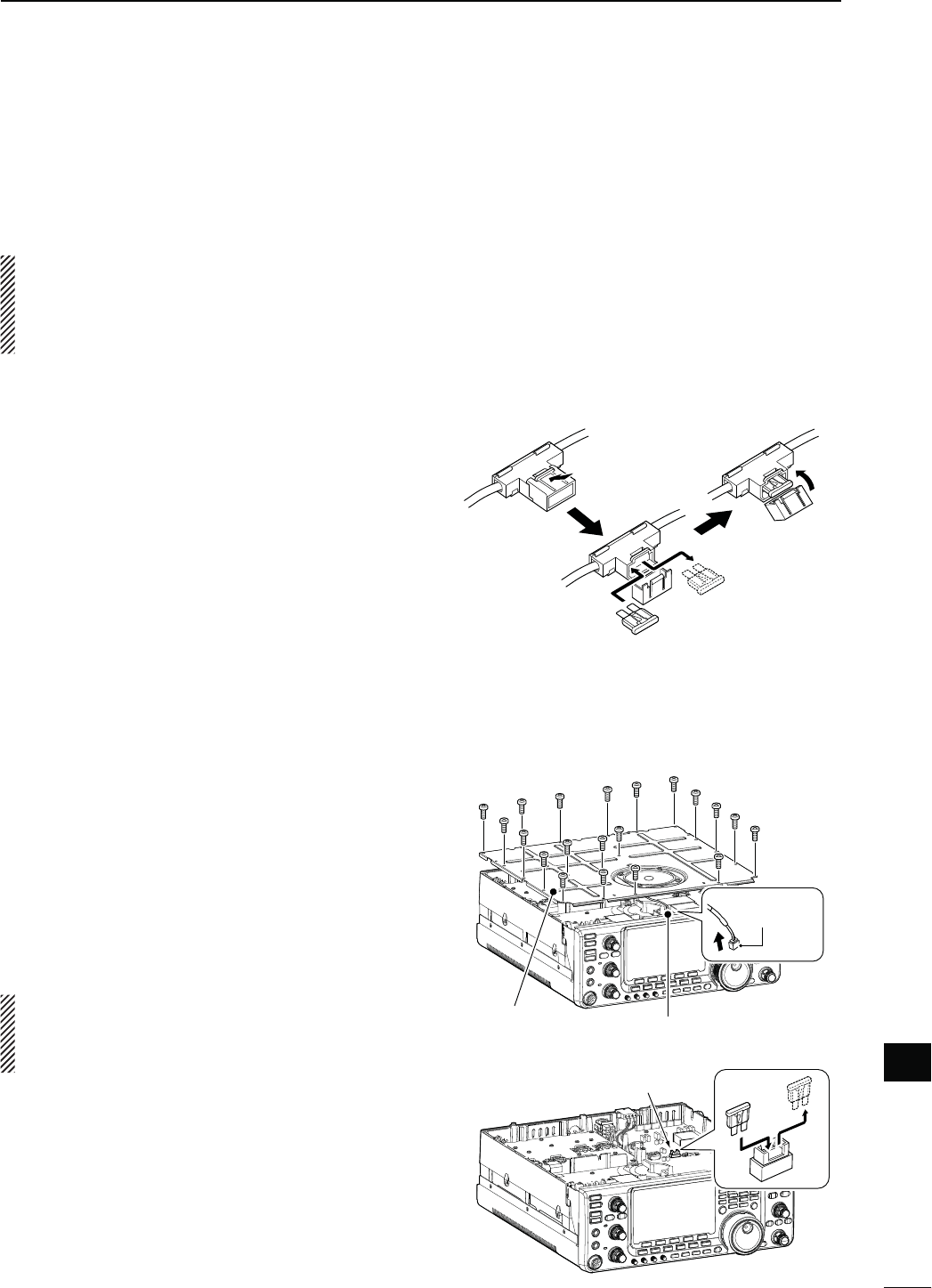
180
17
MAINTENANCE
17
D#IRCUITRYFUSEREPLACEMENT
Except for the power amplifier, the 13.8 V DC from the
DC power cable is applied to all units in the IC-9100,
through the circuitry fuse. This fuse is located in the
PA unit.
q Remove the top cover. (p. 174)
w Remove the 22 screws, then remove the PA shield-
ing plate as shown to the right.
e Remove the speaker cable from the connector on
the PA unit as shown to the right.
r Replace the circuitry fuse as shown in the diagram
to the right.
t Replace the speaker cable, PA shielding plate, top
cover and screws to their original position.
CAUTION:
DO NOT pull the speaker cable when
removing the PA shielding plate, or DO NOT put the
speaker cable under the PA shielding plate when
replacing it. This could damage the transceiver.
ATC 30 A fuse
N&USEREPLACEMENT
If a fuse blows, or the transceiver stops functioning,
find the source of the problem, and repair it. Then re-
place the damaged fuse with a new, adequately rated
fuse.
R WARNING!
Turn OFF the power and disconnect
the DC power cable from the transceiver before per-
forming any work on the transceiver. Otherwise,
there is danger of electric shock, equipment dam-
age and/or fire infury.
The IC-9100 has two fuse types installed for trans-
ceiver protection.
s$#POWERCABLEFUSES .............................. ATC 30 A
s#IRCUITRYFUSE .............................................. ATC 5 A
D$#POWERCABLEFUSEREPLACEMENT
Refer the figure described to the right for the DC power
cable fuse replacement.
Speaker cable
PA shielding plate
ATC 5 A fuse
Connector
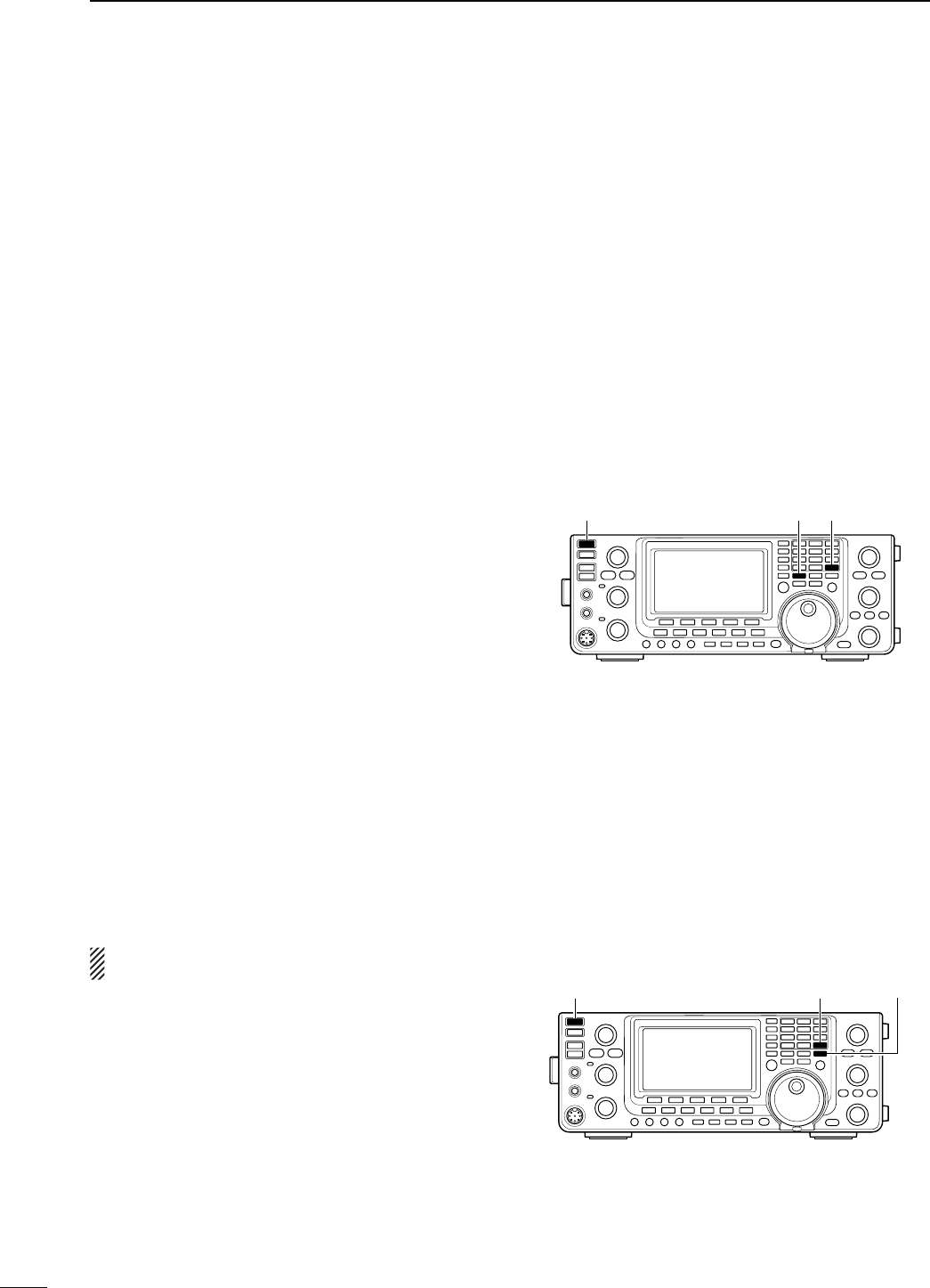
181
17 MAINTENANCE
N2ESETTINGTHE#05
D0ARTIALRESET
If you want to reset the operating parameters to their
default values (VFO frequency, VFO settings, menu
group’s contents) without clearing certain data as de-
scribed below, a partial reset can be performed.
The following data will not be cleared when doing a
Partial reset:
s-EMORYCONTENTS
s#ALLSIGNMEMORIES
s2EPEATERLISTS
s48MESSAGES
s'03MEMORIES
s'03MESSAGES
s-EMORYKEYERCONTENTS
s0ROGRAMMEDUSERBANDEDGEFREQUENCIES
s0ROGRAMMED!UTO2EPEATERFREQUENCYRANGES
s2%&!DJ2EFERENCEFREQUENCYSETTING
q First, turn OFF the transceiver power.
w While holding down [F-INP ENT] and [VFO/MEMO],
push [POWER] to turn ON the power.
s$URING STARTUP THE TRANSCEIVER DISPLAYSh0!24)!,
RESET,” then its initial VFO frequencies when resetting
is complete.
s)FYOUOPERATETHETRANSCEIVERBEFOREh0!24)!,2%3%4v
disappears, the resetting will be cancelled.
e If desired, edit the Set mode settings after reset-
ting.
D!LLRESET
The display may occasionally display erroneous infor-
mation (e.g. when first applying power). This may be
caused externally by static electricity or by other fac-
tors.
If this problem occurs, turn OFF the power. After wait-
ing a few seconds, turn ON the power again. If the
problem persists, perform the following procedure.
NOTE: Resetting the CPU CLEARS all programmed
contents and returns them to their default settings.
q First, turn OFF the transceiver power.
w While holding down [F-INP ENT] and [M-CLR],
push [POWER] to turn ON the power.
s$URINGSTARTUPTHETRANSCEIVERDISPLAYSh!,,#,%!2v
then when resetting is complete, then displays the initial
VFO frequencies.
s)FYOUOPERATETHETRANSCEIVERBEFOREh!,,#,%!2vDIS-
appears, the resetting will be cancelled.
e After resetting, edit the Set mode settings, if de-
sired.
[POWER] [F-INP ENT] [M-CLR]
[POWER] [F-INP ENT] [VFO/MEMO]
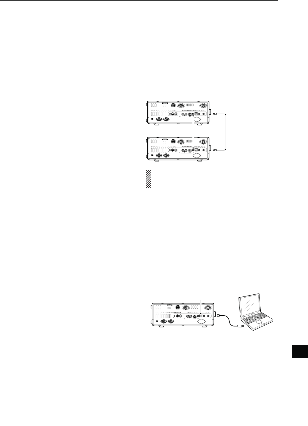
182
17
MAINTENANCE
17
N$ATACLONING
D#LONINGBETWEENTRANSCEIVERS
The IC-9100 has transceiver-to-transceiver data clon-
ing capability.
This function is useful when you want to copy all of the
programmed contents from one IC-9100 to another.
s!MINIPLUGCABLEISREQUIRED0URCHASESEPARATELY
q Connect a mini plug cable to the [REMOTE] jack of
the master and sub transceivers.
s4HEMASTERTRANSCEIVERISUSEDTOSENDDATATOTHESUB
transceiver.
w 3UBTRANSCEIVERSOPERATION
While holding down [F-1] on the sub transceiver,
push [POWER] to turn ON the power and enter the
cloning mode.
-ASTERTRANSCEIVERSOPERATION
While holding down [F-2] on the master transceiver,
push [POWER] to turn ON the power and enter the
cloning mode.
sh#,/.%vAPPEARSANDTHETRANSCEIVERSENTERTHECLONE
standby mode.
sh-vAPPEARSONTHEMASTERTRANSCEIVERSDISPLAYTOINDI-
cate it as the master transceiver.
e Push [OUT](F-5) on the master transceiver.
sh#,/.%/54vAPPEARSONTHEMASTERTRANSCEIVERSDIS-
play, and the bar meter shows that data is being trans-
ferred to the sub-transceiver.
sh#,/.%).vAPPEARSAUTOMATICALLYONTHESUBTRANS-
ceiver’s display, and the bar meter shows that data is
being received from the master transceiver.
r When cloning is finished, turn power OFF, then ON
again to exit the cloning mode.
sh#,/.%%.$vAPPEARSAUTOMATICALLYONTHESUBTRANS-
ceiver’s display after the cloning is completed.
D#LONINGUSINGAPERSONALCOMPUTER
The optional CS-9100 CLONING SOFTWARE is also available to
clone/edit contents with a PC using ICF format files.
Microsoft® Windows® XP (32bit), Windows Vista® (32/64bit)
or Windows® 7 (32/64bit) OS is required.
s!53"CABLEISREQUIREDTOCONNECTTHETRANSCEIVERANDA
PC. (Purchase separately)
[REMOTE] Mini plug cable
(Purchase separately)
[USB]
USB cable
(Purchase separately)
PC
Use as short a mini plug cable as possible.
Depending on the length of the cable, data cloning
cannot be done.
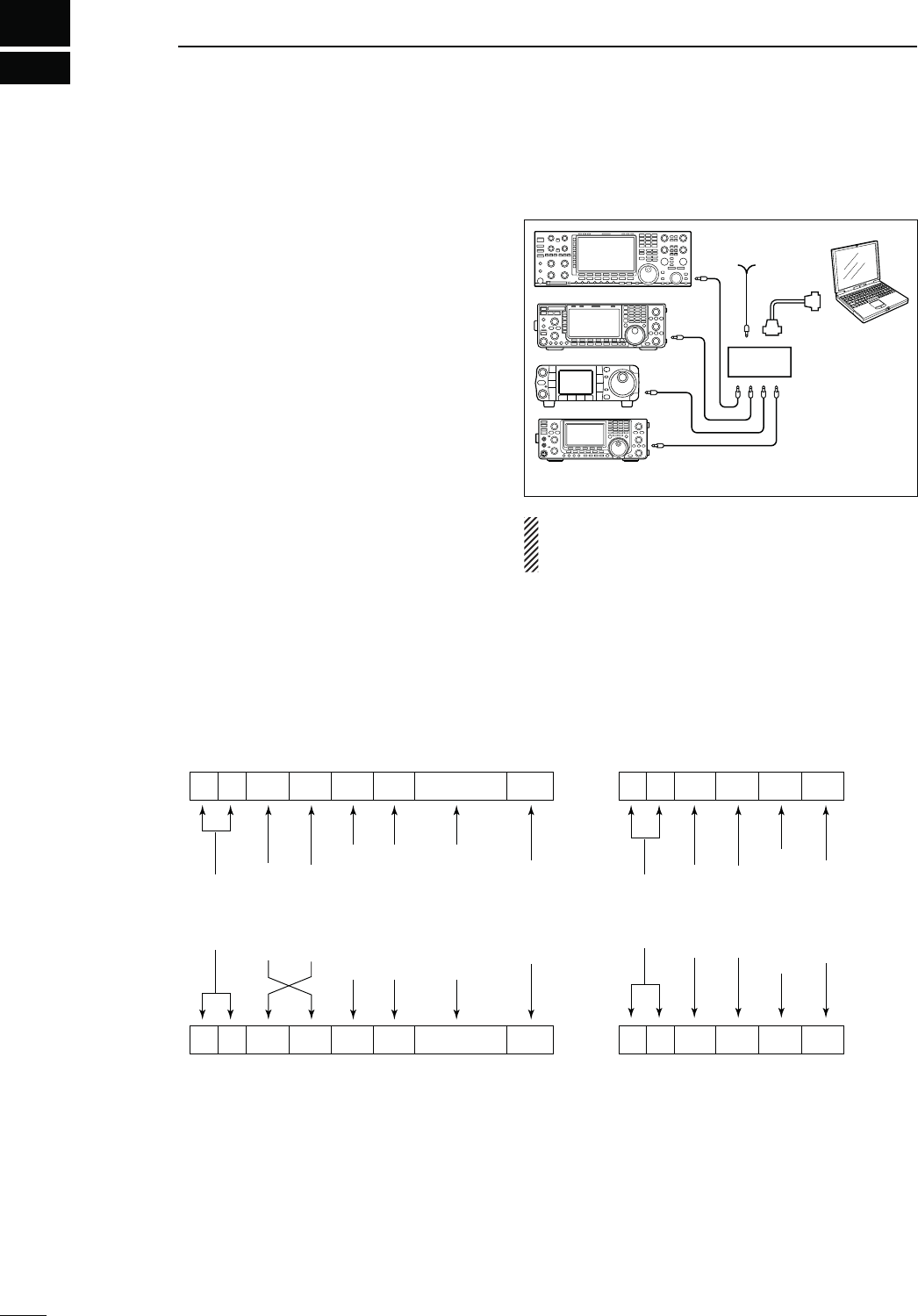
18
183
CONTROL COMMAND
N2EMOTEJACK#)6INFORMATION
Controller to IC-9100
FE FE 7C E0 Cn Sc Data area FD
Preamble
code (fixed)
Transceiver’s
default address
Controller’s
default address
Command number
(see the command table)
Sub command number
(see the command table)
BCD code data such as
for frequency, memory
number entry
(see the data content description)
End of message
code (fixed)
OK message to controller
FE FE E0 7C FB FD
FE FE E0 7C FA FD
Preamble
code (fixed)
Controller’s
default address
Transceiver’s
default address
OK code
(fixed)
End of message
code (fixed)
NG message to controller
NG code
(fixed)
IC-9100 to controller
qwert y u
FE FE E0 7C Cn Sc Data area FD
qwert y u
D#)6CONNECTIONEXAMPLE
The transceiver can be connected through an optional
CT-17 CI-V LEVEL CONVERTER to a PC equipped with an
RS-232C port. The Icom Communications Interface-V
(CI-V) controls the transceiver.
Up to 4 Icom CI-V transceivers or receivers can be
connected to the PC. See p. 167 for setting the CI-V
condition using the set mode.
D$ATAFORMAT
The CI-V system can be operated using the following
data formats. Data formats differ depending on com-
mand numbers. A data area or sub command is added
to some commands.
IC-9100
9−15V DC
PC
ct-17
mini-plug cable
RS-232C
cable
When the transceiver is connected to a PC with the
USB cable (purchased separately), the optional
CT-17 is not required.

184
18
CONTROL COMMAND
18
D#OMMANDTABLE
Cmd.
Sub cmd.
$ATA $ESCRIPTION
00 see p. 190 Send operating frequency for transceive
01 see p. 190 Send operating mode for transceive
02 see p. 191 Read band edge frequencies
03 see p. 190 Read operating frequency
04 see p. 190 Read operating mode
05 see p. 190 Send operating frequency
06 see p. 190 Send operating mode
07 Select VFO mode
00 Select VFO A
01 Select VFO B
A0 Equalize VFO A and VFO B
Or, equalize MAIN and SUB Bands
B0 Exchange VFO A and VFO B
Or, exchange MAIN and SUB Bands
D0 Select MAIN Band
D1 Select SUB Band
08 Select Memory mode
0001 to
0105
Select Memory channel
-#(TO-#(
!B!B
!B
0106 Select Call channel
00 to 19 Select Satellite Memory channel
3ATELLITE-#(TO3ATELLITE
M-CH19)
09 Memory write
0A Memory copy to VFO
0B Memory clear
0C Read offset frequency
0D Send offset frequency
0E 00 Scan stop
01 Programmed/memory scan start
02 Programmed scan start
03 ∂F scan start
12 Fine programmed scan start
13 Fine ∂F scan start
22 Memory scan start
23 Select memory scan start
24 Mode select scan start
A1 Set ∂F scan span ±5 kHz
A2 Set ∂F scan span ±10 kHz
A3 Set ∂F scan span ±20 kHz
A4 Set ∂F scan span ±50 kHz
A5 Set ∂F scan span ±100 kHz
A6 Set ∂F scan span ±500 kHz
A7 Set ∂F scan span ±1 MHz
B0 Set as non-select channel
B1 Set as select channel
( The previously set number by CI-V is set
after turning power ON, or “1” is selected
if no selection is performed.)
D0 Set scan resume OFF
D3 Set scan resume ON
0F Read Split function or duplex setting
00 Set the Split function OFF
01 Set the Split function ON
10 Set simplex operation
11 Set –DUP operation
12 Set +DUP operation
Cmd.
Sub cmd.
$ATA $ESCRIPTION
10 00 Send/read the tuning step 10 Hz (1 Hz)
01 Send/read the tuning step 100 Hz
02 Send/read the tuning step 1 kHz
03 Send/read the tuning stepd 5 kHz
04 Send/read the tuning step 6.25 kHz
05 Send/read the tuning step 9 kHz
06 Send/read the tuning step 10 kHz
07 Send/read the tuning step 12.5 kHz
08 Send/read the tuning step 20 kHz
09 Send/read the tuning step 25 kHz
10 Send/read the tuning step 50 kHz
11 Send/read the tuning step 100 kHz
12 Send/read the tuning step 1 MHz (except
for HF/50 MHz band)
11 00 Send/read attenuator OFF
20 Send/read 20 dB attenuator
12 00 Send/read ANT1 selection
01 Send/read ANT2 selection
13 00 Announce operating frequency, operating
mode and S-meter level with voice syn-
thesizer
01 Announce operating frequency and S-
meter level with voice synthesizer
02 Announce operating mode with voice syn-
thesizer
14 01 0000 to
0255
Send/read [AF] position
MAX##7MAX#7
02 0000 to
0255
Send/read [RF/SQL] position (RF gain
level)
MAX##7OCLOCK
03 0000 to
0255
Send/read [RF/SQL] position (squelch
level)
OCLOCKMAX#7
06 0000 to
0015
Send/read [NR] position
MAX##7MAX#7
07 0000 to
0255
Send/read inner [TWIN PBT] position
MAX##7CENTER
MAX#7
08 0000 to
0255
Send/read outer [TWIN PBT] position
MAX##7CENTER
MAX#7
09 0000 to
0255
Send/read [CW PITCH] position
MAX##7CENTER
MAX#7
0A 0000 to
0255
Send/read [RF POWER] position
MAX##7TOMAX#7
0B 0000 to
0255
Send/read [MIC GAIN] position
MAX##7TOMAX#7
0C 0000 to
0255
3ENDREAD;+%930%%$=POSITION
MAX##7TOMAX#7
0D 0000 to
0255
Send/read [NOTCH] position
MAX##7CENTER
MAX#7
0E 0000 to
0255
Send/read COMP level
TO
0F 0000 to
0255
Send/read Break-IN Delay setting
DTOD
12 0000 to
0255
Send/read NB level
TO
15 0000 to
0255
Send/read Monitor gain
TO
16 0000 to
0255
Send/read VOX gain
TO
17 0000 to
0255
Send/read Anti VOX gain
TO
18 0000 to
0255
Send/read CONTRAST level
TO
19 0000 to
0255
Send/read BRIGHT level
TO

185
18 CONTROL COMMAND
D Command table (continued)
Cmd.
Sub cmd.
$ATA $ESCRIPTION
15 01 00 Read squelch status (squelch close)
01 Read squelch status (squelch open)
02 0000 to
0255
Read S-meter level
333D"
11 0000 to
0255
Read RF power meter
12 0000 to
0255
Read SWR meter
372372
372372
13 0000 to
0255
Read ALC meter
-INTO-AX
14 0000 to
0255
Read COMP meter
D"D"D"
16 02 00 Send/read Preamp OFF
01
Send/read Preamp ON (144/430/1200 MHz)
Send/read Preamp 1 ON (HF/50 MHz)
02 Send/read Preamp 2 ON (HF/50 MHz)
12 01 Send/read AGC FAST
02 Send/read AGC MID
03 Send/read AGC SLOW
22 00 Send/read Noise Blanker OFF
01 Send/read Noise Blanker ON
40 00 Send/read Noise Reduction OFF
01 Send/read Noise Reduction ON
41 00 Send/read Auto Notch function OFF
01 Send/read Auto Notch function ON
42 00 Send/read Repeater tone OFF
01 Send/read Repeater tone ON
43 00 Send/read Tone squelch OFF
01 Send/read Tone squelch ON
44 00 Send/read Speech compressor OFF
01 Send/read Speech compressor ON
45 00 Send/read Monitor function OFF
01 Send/read Monitor function ON
46 00 Send/read VOX function OFF
01 Send/read VOX function ON
47 00 Send/read BK-IN function OFF
01 Send/read Semi BK-IN function ON
02 Send/read Fill BK-IN function ON
48 00 Send/read Manual notch function OFF
01 Send/read Manual notch function ON
4A 00 Send/read AFC function OFF
01 Send/read AFC function ON
4B 00 Send/read DTCS OFF
01 Send/read DTCS ON
4C 00 Send/read VSC function OFF
01 Send/read VSC function ON
4F 00 Send/read Twin Peak Filter OFF
01 Send/read Twin Peak Filter ON
50 00 Send/read Dial lock function OFF
01 Send/read Dial lock function ON
55 00 Send/read 1st IF filter 3 kHz
01 Send/read 1st IF filter 6 kHz
02 Send/read 1st IF filter 15 kHz
56 00 Send/read DSP filter type SHARP
01 Send/read DSP filter type SOFT
57 00 Send/read manual notch width WIDE
01 Send/read manual notch width MID
02 Send/read manual notch width NAR
58 00 Send/read SSB transmit bandwidth WIDE
01 Send/read SSB transmit bandwidth MID
02 Send/read SSB transmit bandwidth NAR
Cmd.
Sub cmd.
$ATA $ESCRIPTION
16 59 00 Send/read Sub band OFF
01 Send/read Sub band ON
5A 00 Send/read Satellite mode OFF
01 Send/read Satellite mode ON
5B 00 Send/read DSQL/CSQL OFF (DV mode
only)
01 Send/read DSQL ON (DV mode only)
02 Send/read CSQL ON (DV mode only)
17 see p. 191 Send CW messages
19 00 Read the transceiver ID
1A 00 see p. 195 Send/read memory contents
01 see p. 191 Send/read band stacking register con-
tents
02 see p. 191 Send/read memory keyer contents*1
03 00 to 49 Send/read the selected filter width
!-(ZK(Z
OTHERTHAN!-MODES(Z
(Z(Z
04 00 to 13
Send/read the selected AGC time constant
/&&!-SECTOSEC
33"#72449SECTOSEC
05 0001 0000 to
0255
Send/read LCD contrast level
LOWTOHIGH
0002 0000 to
0255
Send/read LCD backlight brightness level
DARKTOBRIGHT
0003 0000 to
0255
Send/read beep level
TO
0004 00 Send/read beep level limit OFF
01 Send/read beep level limit ON
0005 00 Send/read confirmation beep OFF
01 Send/read confirmation beep ON
0006 00 Send/read band edge beep OFF
01 Send/read band edge beep ON
(Beep sounds with a default band)
02 Send/read band edge beep with user set-
ting ON
03 Send/read band edge beep with user set-
ting/TX limit ON
0007 0050 to
0200
Send/read beep audio frequency for MAIN
Band
(ZTO(Z
0008 0050 to
0200
Send/read beep audio frequency for SUB
Band
(ZTO(Z
0009 00 Send/read Auto selection for [RF/SQL]
01 Send/read SQL selection for [RF/SQL]
02
Send/read RF+SQL selection for [RF/SQL]
0010 00 Send/read Meter Peak Hold function OFF
01 Send/read Meter Peak Hold function ON
0011 00 Send/read FM/DV Center Error function
OFF
01 Send/read FM/DV Center Error function
ON
0012 00 Send/read Time-Out Timer OFF
01 Send/read 3 min. Time-Out Timer
02 Send/read 5 min. Time-Out Timer
03 Send/read 10 min. Time-Out Timer
04 Send/read 20 min. Time-Out Timer
05 Send/read 30 min. Time-Out Timer
0013 00 Send/read PTT Lock function OFF
01 Send/read PTT Lock function ON
0014 00 Send/read Quick Split function OFF
01 Send/read Quick Split function ON
0015 see p. 192 Send/read Split offset frequency

186
18
CONTROL COMMAND
18
Cmd.
Sub cmd.
$ATA $ESCRIPTION
1A 05 0016 00 Send/read Split Lock function OFF
01 Send/read Split Lock function ON
0017 see p. 192 Send/read Duplex offset frequency
0018 00 Send/read One Touch Repeater DUP–
01 Send/read One Touch Repeater DUP+
0019 00 Send/read Auto Repeater OFF
01 Send/read Auto Repeater ON-1 (for USA
version) or ON (for Korea version)
02 Send/read Auto Repeater ON-2 (for USA
version)
0020 00 Send/read Tuner Auto Start OFF
01 Send/read Tuner Auto Start ON
0021 00 Send/read PTT Tune OFF
01 Send/read PTT Tune ON
0022 00 Send/read antenna selection OFF
01 Send/read manual antenna selection
02 Send/read auto antenna selection
0023 0000 to
0255
Send/read voice synthesizer level
TO
0024 00 Send/read English selection for voice syn-
thesizer speech language
01 Send/read Japanese selection for voice
synthesizer speech language
0025 00 Send/read speech speed slow
01 Send/read speech speed fast
0026 00 Send/read S-meter level announcement
OFF
01 Send/read S-meter level announcement
ON
0027 00 Send/read operating mode announce-
ment (after pushing mode switch) OFF
01 Send/read operating mode announce-
ment (after pushing mode switch) ON
0028 00 Send/read [SPEECH/LOCK] key function
setting
0USH30%%#((OLDDOWN,/#+
01 Send/read [SPEECH/LOCK] key function
setting
0USH,/#+(OLDDOWN30%%#(
0029 00 Send/read number of memo pad channels
5
01 Send/read number of memo pad channels
10
0030 00 Send/read auto TS for [MAIN DIAL] OFF
01 Send/read auto TS for [MAIN DIAL] Low
02 Send/read auto TS for [MAIN DIAL] High
0031 00 Send/read Low selection for microphone
Up/Down speed
01 Send/read High selection for microphone
Up/Down speed
0032 00 Send/read Quick RIT/∂TX clear OFF
01 Send/read Quick RIT/∂TX clear ON
0033 00 Send/read AFC functioning range limit
OFF
01 Send/read AFC functioning range limit ON
0034 00 Send/read Auto Notch selection for SSB
mode
01 Send/read Manual notch selection for
SSB mode
02 Send/read Auto/Manual Notch selection
for SSB mode
0035 00 Send/read Auto Notch selection for AM
mode
01 Send/read Manual Notch selection for AM
mode
02 Send/read Auto/Manual Notch selection
for AM mode
Cmd.
Sub cmd.
$ATA $ESCRIPTION
1A 05 0036 00 Send/read Manual Notch filter width pop-
up OFF
01 Send/read Manual Notch filter width pop-
up ON
0037 00 Send/read BW Popup (PBT) setting OFF
01 Send/read BW Popup (PBT) setting ON
0038 00 Send/read BW Popup (FIL) setting OFF
01 Send/read BW Popup (FIL) setting ON
0039 00 Send/read SSB/CW Synchronous Tuning
function OFF
01 Send/read SSB/CW Synchronous Tuning
function ON
0040 00 Send/read LSB selection for CW normal
side
01 Send/read USB selection for CW normal
side
0041 00 3ENDREAD+%9%22OOTSELECTIONFOR
keyer 1st menu
01 3ENDREAD+%9%23%.$SELECTIONFOR
keyer 1st menu
0042 00 Send/read GPS-Root selection for GPS
1st Menu
01 Send/read GPS-POS selection for GPS
1st Menu
0043 00 Send/read external preamplifier (AG-25)
control for 144 MHz band OFF
01 Send/read external preamplifier (AG-25)
control for 144 MHz band ON
0044 00 Send/read external preamplifier (AG-35)
control for 430 MHz band OFF
01 Send/read external preamplifier (AG-35)
control for 430 MHz band ON
0045 00 Send/read external preamplifier (AG-
1200) control for 1200 MHz band OFF
01 Send/read external preamplifier (AG-
1200) control for 1200 MHz band ON
0046 00 Send/read Separate selection for the ex-
ternal speaker output method
01 Send/read Mix selection for the external
speaker output method
0047 00 Send/read Separate selection for the
headphone audio output method
01 Send/read Mix selection for the head-
phone audio output method
02 Send/read Auto selection for the head-
phone audio output method
0048 00 Send/read SUB Band audio mute during
transmit on the main band OFF
01 Send/read SUB Band audio mute during
transmit on the main band ON
0049 00 Send/read MAIN selection for the [ACC]
AF/SQL line output
01 Send/read SUB selection for the [ACC]
AF/SQL line output
0050 00 Send/read MAIN selection for the [DATA]
AF/SQL line output
01 Send/read SUB selection for the [DATA]
AF/SQL line output
0051 00 Send/read VSEND select OFF
01 Send/read UHF Only selection for VSEND
02 Send/read VSEND select ON
0052 00 Send/read external keypad OFF
01 3ENDREAD+%9%23%.$SELECTIONFORTHE
external keypad
0053 00 Send/read USB audio squelch OFF
(OPEN)
01 Send/read USB audio squelch ON

187
18 CONTROL COMMAND
D Command table (continued)
Cmd.
Sub cmd.
$ATA $ESCRIPTION
1A 05 0054 0000 to
0255
Send/read USB modulation level
TO
0055 00 Send/read 9600 bps mode OFF
01 Send/read 9600 bps mode ON
0056 00 Send/read MIC selection for the modula-
tion input during DATA mode OFF
01 Send/read ACC selection for the modula-
tion input during DATA mode OFF
02 Send/read MIC+ACC selection for the
modulation input during DATA mode OFF
03 Send/read USB selection for the modula-
tion input during DATA mode OFF
0057 00 Send/read MIC selection for the modula-
tion input during DATA mode ON
01 Send/read ACC selection for the modula-
tion input during DATA mode ON
02 Send/read MIC+ACC selection for the
modulation input during DATA mode ON
03 Send/read USB selection for the modula-
tion input during DATA mode ON
0058 00 Send/read CI-V transceive OFF
01 Send/read CI-V transceive ON
0059 00 Send/read no function selection for
“USB2” (COM port) function
01 3ENDREAD2449SELECTIONFORh53"v
(COM port) function
02 Send/read DVdat selection for “USB2”
(COM port) function
0060 00 Send/read no function selection for
[DATA1] function
01 3ENDREAD2449SELECTIONFOR;$!4!=
function
02 Send/read DVdat selection for [DATA1]
function
0061 00 Send/read OFF selection for GPS Out
01 Send/read DATA->USB2 selection for
GPS Out
0062 00 Send/read 4800 bps selection for GPS
position data transmission speed of
[DATA1]
01 Send/read 9600 bps selection for GPS
position data transmission speed of
[DATA1]
0063 00 3ENDREADBPSSELECTIONFOR2449
Decode Baud rate
01 3ENDREADBPSSELECTIONFOR2449
Decode Baud rate
02 3ENDREADBPSSELECTIONFOR2449
Decode Baud rate
03 3ENDREADBPSSELECTIONFOR2449
Decode Baud rate
04 3ENDREADBPSSELECTIONFOR2449
Decode Baud rate
0064 00 Send/read Calibration marker OFF
01 Send/read Calibration marker ON
0065 0000 to
0255
Send/read reference frequency
TO
0066 00 to 10 Send/read COMP level
-INIMUMTO-AXIMUM
0067 see p. 192 Send/read SSB RX HPF/LPF setting
0068 00 to 10 Send/read SSB RX Tone (Bass) level
nTO
0069 00 to 10 Send/read SSB RX Tone (Treble) level
nTO
0070 00 to 10 Send/read SSB TX Tone (Bass) level
nTO
0071 00 to 10 Send/read SSB TX Tone (Treble) level
nTO
0072 see p. 192 Send/read SSB TX bandwidth for WIDE
Cmd.
Sub cmd.
$ATA $ESCRIPTION
1A 05 0073 see p. 192 Send/read SSB TX bandwidth for MID
0074 see p. 192 Send/read SSB TX bandwidth for NAR-
ROW
0075 see p. 192 Send/read AM RX HPF/LPF setting
0076 00 to 10 Send/read AM RX tone (Bass) level
nTO
0077 00 to 10 Send/read AM RX Tone (Treble) level
nTO
0078 00 to 10 Send/read AM TX tone (Bass) level
nTO
0079 00 to 10 Send/read AM TX Tone (Treble) level
nTO
0080 see p. 192 Send/read FM RX HPF/LPF setting
0081 00 to 10 Send/read FM RX tone (Bass) level
nTO
0082 00 to 10 Send/read FM RX Tone (Treble) level
nTO
0083 00 to 10 Send/read FM TX tone (Bass) level
nTO
0084 00 to 10 Send/read FM TX Tone (Treble) level
nTO
0085 see p. 192 Send/read DV RX HPF/LPF setting
0086 00 to 10 Send/read DV RX tone (Bass) level
nTO
0087 00 to 10 Send/read DV RX Tone (Treble) level
nTO
0088 00 to 10 Send/read DV TX tone (Bass) level
nTO
0089 00 to 10 Send/read DV TX Tone (Treble) level
nTO
0090 see p. 192 Send/read CW RX HPF/LPF setting
0091 see p. 192 3ENDREAD244928(0&,0&SETTING
0092 00 Send/read Normal selection for contest
number style
01 Send/read “190 䊻ANO” selection for con-
test number style
02 Send/read “190 䊻ANT” selection for con-
test number style
03 Send/read “90 䊻NO” selection for con-
test number style
04 Send/read “90 䊻NT” selection for contest
number style
0093 01 Send/read M1 selection for count up trig-
ger channel
02 Send/read M2 selection for count up trig-
ger channel
03 Send/read M3 selection for count up trig-
ger channel
04 Send/read M4 selection for count up trig-
ger channel
0094 0001 to
9999
Send/read present number
TO
0095 0000 to
0255
Send/read CW sidetone gain
TO
0096 00 Send/read CW sidetone gain limit OFF
01 Send/read CW sidetone gain limit ON
0097 01 to 60 Send/read CW keyer repeat time
SECTOSEC
0098 00 Send/read Normal selection for message
display
01 Send/read Message selection for mes-
sage display
0099 28 to 45 Send/read CW keyer dot/dash ratio
TO
0100 00
Send/read 2 msec. selection for CW Rise time
01
Send/read 4 msec. selection for CW Rise time
02
Send/read 6 msec. selection for CW Rise time
03
Send/read 8 msec. selection for CW Rise time
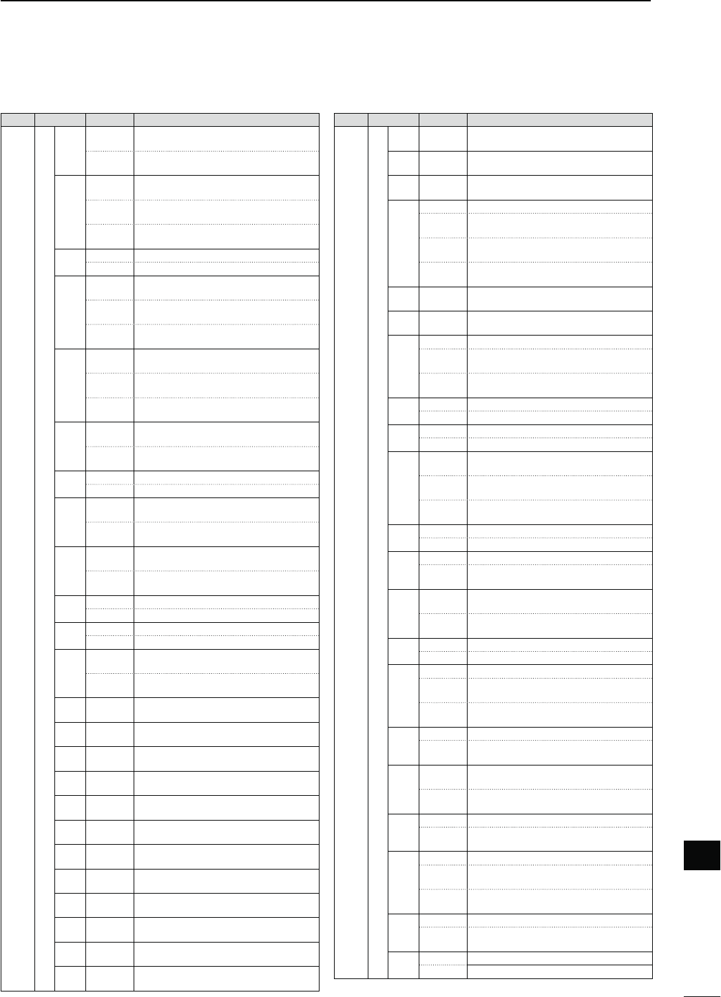
188
18
CONTROL COMMAND
18
Cmd.
Sub cmd.
$ATA $ESCRIPTION
1A 05 0101 00 Send/read Normal selection for paddle
polarity
01 Send/read Reverse selection for paddle
polarity
0102 00 Send/read Straight selection for keyer
type
01 Send/read BUG-Key selection for keyer
type
02 Send/read ELEC-Key selection for keyer
type
0103 00 Send/read Mic. up/down keyer OFF
01 Send/read Mic. up/down keyer ON
0104 00 3ENDREAD(ZSELECTIONFOR2449
mark frequency
01 3ENDREAD(ZSELECTIONFOR2449
mark frequency
02 3ENDREAD(ZSELECTIONFOR2449
mark frequency
0105 00 3ENDREAD(ZSELECTIONFOR2449SHIFT
width
01 3ENDREAD(ZSELECTIONFOR2449SHIFT
width
02 3ENDREAD(ZSELECTIONFOR2449SHIFT
width
0106 00 3ENDREAD.ORMALSELECTIONFOR2449
keying polarity
01 3ENDREAD2EVERSESELECTIONFOR2449
keying polarity
0107 00 3ENDREAD2449DECODE53/3/&&
01 3ENDREAD2449DECODE53/3/.
0108 00 Send/read “CR,LF,CR+LF” selection for
2449DECODENEWLINECODE
01 3ENDREADh#2,&vSELECTIONFOR2449
decode new line code
0109 00 Send/read 2 lines selection for number of
2449DECODERLINE
01 Send/read 3 lines selection for number of
2449DECODERLINE
0110 00 Send/read Scan speed Low
01 Send/read Scan speed High
0111 00 Send/read Scan resume OFF
01 Send/read Scan resume ON
0112 00 Send/read OFF selection for MAIN DIAL
function during a scan
01 Send/read Up/Down selection for MAIN
DIAL function during a scan
0113 0000 to
0255
Send/read NB level (HF/50 MHz)
TO
0114 00 to 09 Send/read NB depth (HF/50 MHz)
TO
0115 0000 to
0255
Send/read NB width (HF/50 MHz)
TO
0116 0000 to
0255
Send/read NB level (144 MHz)
TO
0117 00 to 09 Send/read NB depth (144 MHz)
TO
0118 0000 to
0255
Send/read NB width (144 MHz)
TO
0119 0000 to
0255
Send/read NB level (430 MHz)
TO
0120 00 to 09 Send/read NB depth (430 MHz)
TO
0121 0000 to
0255
Send/read NB width (430 MHz)
TO
0122 0000 to
0255
Send/read NB level (1200 MHz)
TO
0123 00 to 09 Send/read NB depth (1200 MHz)
TO
0124 0000 to
0255
Send/read NB width (1200 MHz)
TO
Cmd.
Sub cmd.
$ATA $ESCRIPTION
1A 05 0125 0000 to
0255
Send/read VOX gain
TO
0126 0000 to
0255
Send/read ANTI-VOX gain
TO
0127 00 to 20 Send/read VOX delay time
SECTOSEC
0128 00 Send/read VOX voice delay OFF
01 Send/read Short selection for VOX voice
delay
02 Send/read Mid selection for VOX voice
delay
03 Send/read Long selection for VOX voice
delay
0129 0000 to
0255
Send/read BK-IN delay time
DTOD
0130 0000 to
0255
Send/read MONITOR gain
TO
0131 00 Send/read Standby Beep OFF
01 Send/read ON-1 selection for Standby
Beep
02 Send/read ON-2 selection for Standby
Beep
0132 00 Send/read Auto Reply OFF
01 Send/read Auto Reply ON
0133 00 Send/read PTT selection for DV Data TX
01 Send/read Auto selection for DV Data TX
0134 00 Send/read Auto selection for Digital Moni-
tor
01 Send/read Digital selection for Digital
Monitor
02 Send/read Analog selection for Digital
Monitor
0135 00 Send/read Digital RPT Set OFF
01 Send/read Digital RPT Set ON
0136 00 Send/read RX Call Sign Auto Write OFF
01 Send/read Auto selection for RX Call Sign
Auto Write
0137 00 Send/read RX RPT Call Sign Auto Write
OFF
01 Send/read Auto selection for RX RPT Call
Sign Auto Write
0138 00 Send/read DV Auto Detect OFF
01 Send/read DV Auto Detect ON
0139 00 Send/read Call Sign Edit Record OFF
01 Send/read Select selection for Call Sign
Edit Record
02 Send/read Auto selection for Call Sign
Edit Record
0140 00 Send/read Gateway Auto Set OFF
01 Send/read Auto selection for Gateway
Auto Set
0141 00 Send/read ALL selection for RX Record
(RPT)
01 Send/read Latest Only selection for RX
Record (RPT)
0142 00 Send/read RX Call Sign Auto Display OFF
01 Send/read Auto selection for RX Call Sign
Auto Display
0143 00 Send/read TX Call Sign Display OFF
01 Send/read UR selection for TX Call Sign
Display
02 3ENDREAD-9SELECTIONFOR48#ALL3IGN
Display
0144 00 Send/read RX Message Display OFF
01 Send/read Auto selection for RX Message
Display
0145 00 Send/read Scrolling speed slow
01 Send/read Scrolling speed fast

189
18 CONTROL COMMAND
Cmd.
Sub cmd.
$ATA $ESCRIPTION
1A 05 0146 00 Send/read DR Call Sign Popup OFF
01 Send/read DR Call Sign Popup ON
0147 00 Send/read Opening Call Sign OFF
01 Send/read Opening Call Sign ON
0148 00 Send/read BK function OFF
01 Send/read BK function ON
0149 00 Send/read EMR mode OFF
01 Send/read EMR mode ON
0150 0000 to
0255
Send/read EMR AF Level
TO
0151 00 Send/read 4800 bps selection for GPS
Receiver Baud
01 Send/read 9600 bps selection for GPS
Receiver Baud
0152 00 Send/read ddd˚mm.mm’ selection for Po-
sition Format
01 Send/read ddd˚mm’ss” selection for Posi-
tion Format
0153 00 Send/read Meter selection for the display-
ing unit
01 Send/read Feet/Mile selection for the dis-
playing unit
0154 00 Send/read North REF selection for com-
pass direction
01 Send/read South REF selection for com-
pass direction
0155 see p. 192 Send/read UTC Offset
0156 00 Send/read GPS Indicator OFF
01 Send/read GPS Indicator ON
0157 00 3ENDREAD'03SELECTIONFOR-90OSITION
input method
01 3ENDREAD-ANUALSELECTIONFOR-90OSI-
tion input method
0158 see p. 192 Send/read my position information
0159 see p. 193 Send/read Alarm Area1
0160 00 Send/read Limited selection for Alarm
Area2
01 Send/read Extended selection for Alarm
Area2
02 Send/read Both selection for Alarm Area2
0161 00 Send/read GPS Auto TX OFF
01 Send/read 5 sec. selection for GPS Auto
TX interval
02 Send/read 10 sec. selection for GPS Auto
TX interval
03 Send/read 30 sec. selection for GPS Auto
TX interval
04 Send/read 1 min. selection for GPS Auto
TX interval
05 Send/read 3 min. selection for GPS Auto
TX interval
06 Send/read 5 min. selection for GPS Auto
TX interval
07 Send/read 10 min. selection for GPS Auto
TX interval
08 Send/read 30 min. selection for GPS Auto
TX interval
0162 00 Send/read Disable selection for GPS TX
Mode
01 Send/read GPS selection for GPS TX
Mode
02 Send/read GPS-A selection for GPS TX
Mode
0163 00 Send/read GPS Sentence (RMC) OFF
01 Send/read GPS Sentence (RMC) ON
0164 00 Send/read GPS Sentence (GGA) OFF
01 Send/read GPS Sentence (GGA) ON
D Command table (continued)
Cmd.
Sub cmd.
$ATA $ESCRIPTION
1A 05 0165 00 Send/read GPS Sentence (GLL) OFF
01 Send/read GPS Sentence (GLL) ON
0166 00 Send/read GPS Sentence (GSA) OFF
01 Send/read GPS Sentence (GSA) ON
0167 00 Send/read GPS Sentence (VTG) OFF
01 Send/read GPS Sentence (VTG) ON
0168 00 Send/read GPS Sentence (GSV) OFF
01 Send/read GPS Sentence (GSV) ON
0169 see p. 193 Send/read Unproto Address
0170 00 Send/read position data extension OFF
01 Send/read Course/Speed selection for
position data extension
0171 00 Send/read Time Stamp OFF
01 Send/read DHM selection for Time Stamp
02 Send/read HMS selection for Time Stamp
0172 00 to 16 Send/read GPS-A Symbol
!MBULANCE"US&IRE4RUCK
"ICYCLE9ACHT(ELICOPTER
3MALL!IRCRAFT3HIP#AR
-OTORCYCLE"ALLOON*EEP
264RUCK6AN
(OUSE14(6(&/THER
0173 see p. 193 Send/read GPS-A Symbol Other
0174 00 to 16 Send/read GPS-A SSID
TO
0175 see p. 193 Send/read Comment
0176 see p. 193 Send/read Comment (Extension)
0177 see p. 193 Send/read GPS TX Message
06 see p. 193 Send/read DATA mode selection
07 see p. 196 Send/read Satellite memory contents
1B 00 see p. 193 Send/read Repeater tone frequency
01 see p. 193 Send/read Tone squelch frequency
02 see p. 193 Send/read DTCS code and polarity
07 see p. 193 Send/read CSQL code (DV mode)
1C 00 00 Send/read Transceiver’s status (RX)
01 Send/read Transceiver’s status (TX)
01 00 Send/read Antenna tuner OFF (through)
01 Send/read Antenna tuner ON
02 Send/read Manual tuning selection
02 00 Send/read Transmit frequency monitor
check OFF
01 Send/read Transmit frequency monitor
check ON
1E 00 Read number of available TX frequency
band
01 see p. 191 Read TX band edge frequencies
02 Read number of user-set TX frequency
band
03 see p. 191 Send/read User-set TX band edge fre-
quencies
1F 00 see p. 193 3ENDREAD$6-9CALLSIGN
01 see p. 194 Send/read DV TX call signs
02 see p. 194 Send/read DV TX message
20 00 00 00*2Send/read Auto DV RX Callsigns output
OFF
01*2Send/read Auto DV RX Callsigns output
ON
01 see p. 194 Output DV RX Callsigns
02 see p. 194 Read DV RX Callsigns
01 00 00*2Send/read Auto DV RX message output
OFF
01*2Send/read Auto DV RX message output
ON
01 see p. 194 Output DV RX message
02 see p. 194 Read DV RX message
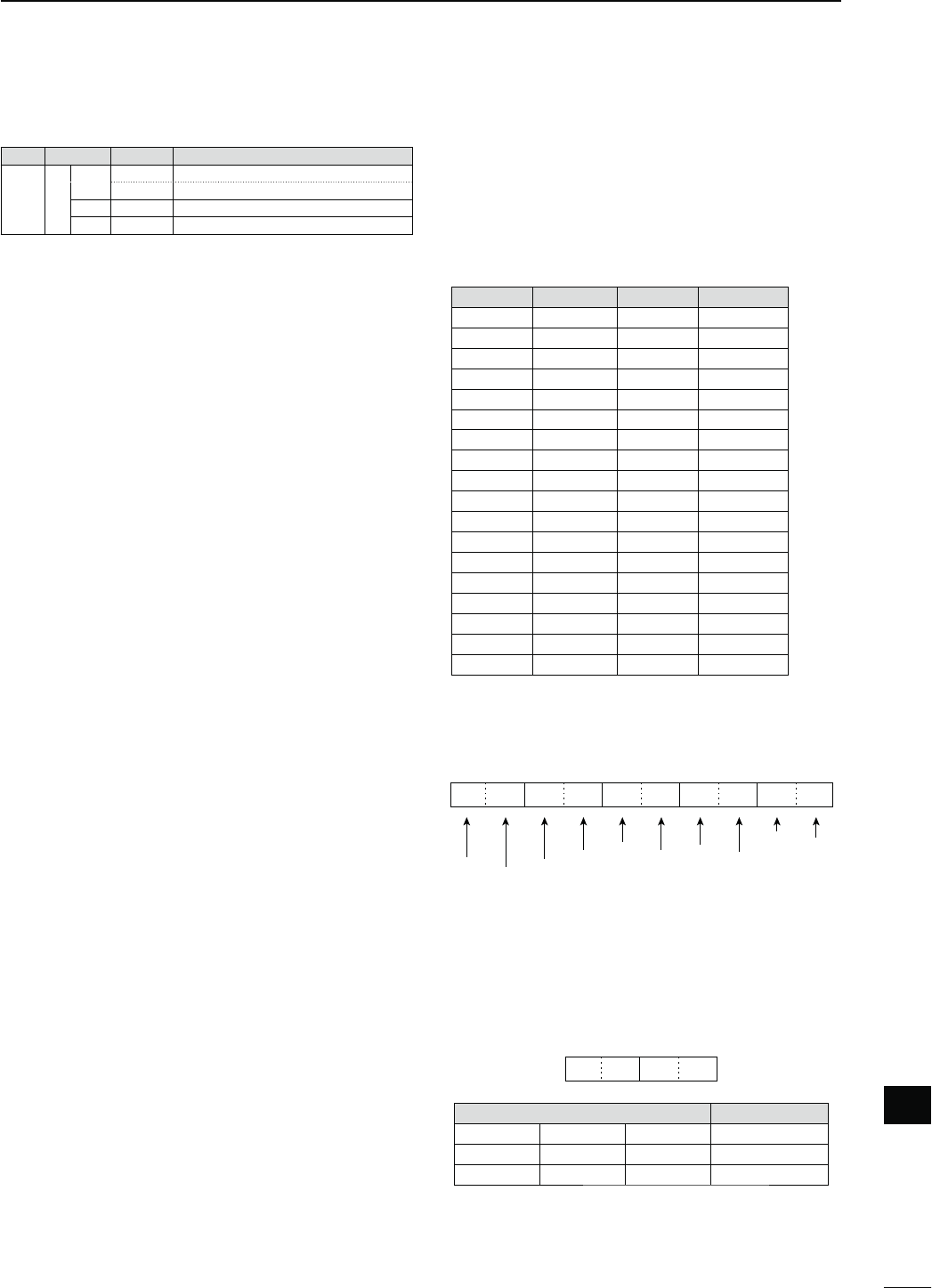
190
18
CONTROL COMMAND
18
Cmd.
Sub cmd.
$ATA $ESCRIPTION
20 02 00 00*2Send/read Auto DV RX status output OFF
01*2Send/read Auto DV RX status output ON
01 see p. 194 Output DV RX status
02 see p. 194 Read DV RX status
*1 The counter can be inserted into only one channel.
*2 Output setting is automatically turned OFF after turning
the power OFF, then ON.
s#HARACTERCODESETTING
Command : 1A 00, 1A 05 0169, 1A 05 0173,
1A 05 0175, 1A 05 0176, 1A 05 0177,
1F 02, 20 0001, 20 0002, 20 0101,
20 0102
#HARACTER ASCII code #HARACTER ASCII code
A–Z 41–5A a–z 61–7A
0–9 30–39 Space 20
!21#23
$2425
26 <5C
?3F" 22
’27` 60
^5E+2B
–2D12A
⁄2F.2E
,2C: 3A
3B 3D
<3C> 3E
(28 )29
[5B ]5D
{7B }7D
¦7C _5F
¯7E@40
s/PERATINGFREQUENCY
Command : 00, 03, 05
q
XXXXX
we
X
rt
XX XX
10 Hz digit: 0–9
1 Hz digit: 0–9
1 kHz digit: 0–9
100 Hz digit: 0–9
100 kHz digit: 0–9
10 kHz digit: 0–9
10 MHz digit: 0–9
1 MHz digit: 0–9
1000 MHz digit: 0–1
100 MHz digit: 0–4
s/PERATINGMODE
Command : 01, 04, 06
q
XXXX
w
q /PERATINGMODE w &ILTERSETTING
00: LSB 03: CW 07: CW-R 01: FIL1
01: USB 2449 24492 02: FIL2
02: AM 05: FM 17: DV 03: FIL3
Filter setting (w) can be skipped with command 01
and 06. In that case, “FIL1” is automatically selected
with command 01, and the default filter setting of the
operating mode is automatically selected with com-
mand 06.
D$ATACONTENTDESCRIPTION
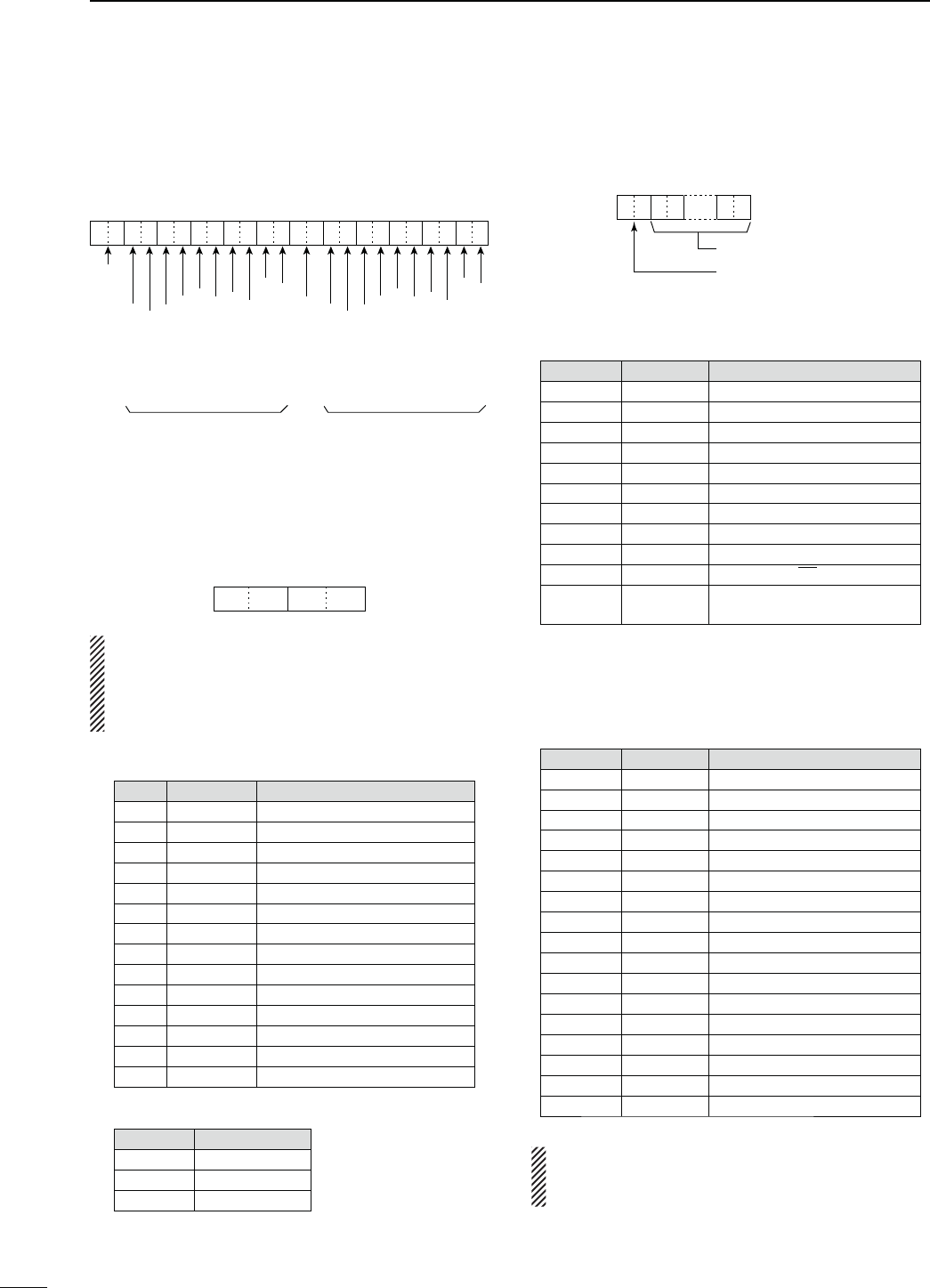
191
18 CONTROL COMMAND
s"ANDEDGEFREQUENCYSETTING
Command 02*, 1E 01, 1E 03
q
XXX
wertyuio!0 !1 !2
XXXXXXXXX2DXXXXXXXXXX
10 Hz digit: 0–9
1 Hz digit: 0–9
1 kHz digit: 0–9
100 Hz digit: 0–9
100 kHz digit: 0–9
10 kHz digit: 0–9
10 MHz digit: 0–9
1 MHz digit: 0–9
1000 MHz digit: 0–1
100 MHz digit: 0–9
10 Hz digit: 0–9
1 Hz digit: 0–9
1 kHz digit: 0–9
100 Hz digit: 0–9
100 kHz digit: 0–9
10 kHz digit: 0–9
10 MHz digit: 0–9
1 MHz digit: 0–9
1000 MHz digit: 0–1
100 MHz digit: 0–9
Separator (fixed)
Lower edge Higher edge
Edge number*: 01–30
* Edge number setting is not necessary with com-
mand 02.
s"ANDSTACKINGREGISTER
Command : 1A 01
q
XXXX
w
When sending the contents, the codes, such as op-
erating frequency and operating mode*, should be
added after the register code, as shown below.
* See t to %1 on ‘Memory content setting’ for details.
(p. 195)
q Frequency band code
Code &REQBAND &REQUENCYRANGEUNIT-(Z
01 1.8 1.800000– 1.999999
02 3.5 3.400000– 4.099999
03 7 6.900000– 7.499999
04 10 9.900000–10.499999
05 14 13.900000–14.499999
06 18 17.900000–18.499999
07 21 20.900000–21.499999
08 24 24.400000–25.099999
09 28 28.000000–29.999999
10 50 50.000000–54.000000
11 VHF 108.000000–174.000000
12 UHF 420.000000–480.000000
13 1.2G 1240.000000–1320.000000
14 GENE Other than above
w Register code
Code 2EGISTERED.O
01 1 (latest)
02 2
03 3 (oldest)
For example, when reading the oldest contents in the
21 MHz band, the code “0703” is used.
s-EMORYKEYERCONTENTS
Command : 1A 02
X
q: Channel data
w–&1: Text data
XXX…… XX
01: M1
02: M2
03: M3
04: M4
s#HARACTERSCODE
#HARACTER ASCII code $ESCRIPTION
0–9 30–39 Number
A–Z 41–5A Alphabetical characters
a–z 61–7A Alphabetical characters
space 20 Word space
/ 2F Symbol
? 3F Symbol
, 2C Symbol
. 2E Symbol
@ 40 Symbol
^5E
e.g., to send BT, enter ^BT
12A Inserts contest number (can be
used for 1 channel only)
s#7MESSAGECONTENTS
Command : 17
Set a CW message of up to 30 characters.
s#HARACTERSCODE
#HARACTER ASCII code $ESCRIPTION
0–9 30–39 Number
A–Z 41–5A Alphabetical characters
a–z 61–7A Alphabetical characters
space 20 Word space
/ 2F Symbol
? 3F Symbol
. 2E Symbol
– 2D Symbol
, 2C Symbol
: 3A Symbol
’ 27 Symbol
( 28 Symbol
) 29 Symbol
3D Symbol
+ 2B Symbol
” 22 Symbol
@ 40 Symbol
s“FF” stops sending CW messages.
s“^” is used to transmit a string of characters with
no inter-character space.
D Data content description (continued)
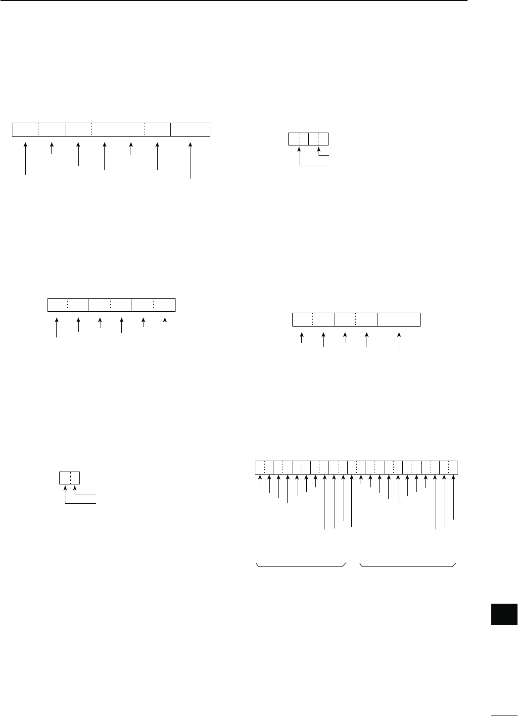
192
18
CONTROL COMMAND
18
s3PLITOFFSETFREQUENCYSETTING
Command : 1A 05 0015
1 kHz digit: 0–9
100 Hz digit: 0 (fixed)
100 kHz digit: 0–9
10 kHz digit: 0–9
10 MHz digit: 0 (fixed)
1 MHz digit: 0–9
Direction:
00: + direction
01: – direction
q
0XXXXXX
we
0
r
s$UPLEX/FFSETFREQUENCYSETTING
Command : 1A 05 0017
q
XXXXX
we
X
1 kHz digit: 0–9
100 Hz digit: 0–9
100 kHz digit: 0–9
10 kHz digit: 0–9
10 MHz digit*: 0–9
1 MHz digit: 0–9
*10 MHz digit can be entered on only
the 1200 MHz frequency band.
s33"TRANSMISSIONBANDWIDTHSETTING
Command : 1A 05 0072, 0073, 0074
XX
Lower edge
Higher edge
Lower edge
0: 100Hz
1: 200Hz
2: 300Hz
3: 500Hz
Higher edge
0: 2500Hz
1: 2700Hz
2: 2800Hz
3: 2900Hz
s28(0&AND,0&SETTINGSINEACH
OPERATINGMODE
Command : 1A 05 0067, 0075, 0080, 0085, 0090,
0091
XXXX
LPF (upper side)
HPF (lower side)
HPF
00: through
01 to 20: 100 to 2000 Hz
LPF
05 to 24: 500 to 2400 Hz
25: through
Set the LPF value larger than HPF one.
s54#/FFSETSETTING
Command : 1A 05 0155
q
XXXX
we
X X
10 hour digit: 0–1
1 hour digit: 0–9
10 min. digit: 0–5
1 min. digit: 0–9
Direction
00=+ direction
01=– direction
s-YPOSITIONDATASETTING
Command : 1A 05 0158
q
X
wertyuio!0 !1
XXXXXX00X0XXXXXXXX00X
Latitude Longitude
10 degree digit: 0–9
1 degree digit: 0–9
10 min. digit: 0–5
1 min. digit: 0–9
0.1 min. digit: 0–9
0.01 min. digit: 0–9
0.001 min. digit: 0–9
0 (fixed)
0 (fixed)
S*=0/N*=1
0 (fixed)
100 degree digit: 0–1
10 degree digit: 0–9
1 degree digit: 0–9
10 min. digit: 0–5
1 min. digit: 0–9
0.1 min. digit: 0–9
0.01 min. digit: 0–9
0.001 min. digit: 0–9
0 (fixed)
0 (fixed)
W*=0/E*=1
*S: South latitude N: North latitude
W: West longitude E: East longitude
193
18 CONTROL COMMAND
s!LARMAREASETTING
Command : 1A 05 0159
q
XXXX0
we
0
10 min. digit: 0–5
1 min. digit: 0–9
0.1 min. digit: 0–9
0.01 min. digit: 0–9
0.001 min. digit: 0–9
0 (fixed)
s5NPROTO!DDRESSSETTING
Command : 1A 05 0169
Set an unproto address of up to 56 characters.
See ‘Character code setting’ for details. (p. 190)
s'03!3YMBOLSETTING
Command : 1A 05 0173
XXXX
Second digit
First digit
b<TO!TO:CANBEUSEDFORTHEFIRSTDIGIT
character.
See ‘Character code setting’ for the second digit
character. (p. 190)
s#OMMENTSETTING
Command : 1A 05 0175
Set a comment of up to 43 characters.
See ‘Character code setting’ for details. (p. 190)
s#OMMENT%XTENSIONSETTING
Command : 1A 05 0176
Set a comment of up to 36 characters.
See ‘Character code setting’ for details. (p. 190)
s'03MESSAGESETTING
Command : 1A 05 0177
Set a GPS message of up to 20 characters.
See ‘Character code setting’ for details. (p. 190)
s$ATAMODEWITHlLTERWIDTHSETTING
Command : 1A 06
XXXX
qw
00: Data mode OFF
01: FIL1
02: FIL2
03: FIL3
00: Data mode OFF
01: Data mode ON
s2EPEATERTONETONESQUELCHFREQUENCY
SETTING
Command : 1B 00, 1B 01
q*ew
00XXXX
0 (fixed)
0 (fixed)
100 Hz digit
10 kHz digit
1 Hz digit
0.1 Hz digit
*Not necessary when setting a frequency.
s$4#3CODEANDPOLARITYSETTING
Command : 1B 02
qew
XX0XXX
Transmit polarity:
0: Normal
1: Reverse
Receive polarity:
0: Normal
1: Reverse
0 (fixed)
First digit: 0–7
Second digit: 0–7
Third digit: 0–7
s$IGITALCODESQUELCHSETTING
Command : 1B 07
XX
q
Second digit: 0–9
First digit: 0–9
s$6-9CALLSIGNSETTING
Command : 1F 00
Set your own call sign and note of up to 12 charac-
ters.
XX XXXXXXXXXX
o–!2q–i
……
q–i9OUROWNCALLSIGNSETTING
o–!2 Note setting
D Data content description (continued)
194
18
CONTROL COMMAND
18
s$648CALLSIGNSSETTING
Command : 1F 01
Set “UR,” “R1” and “R2” call signs of up to 8 characters.
XX
……
XX XXXXXXXX
……
!7–@4o–!6q–i
……
q–i UR (Destination) call sign setting
o–!6 R1 (Access/Area repeater) call sign setting
!7–@4 R2 (Link/Gateway repeater) call sign setting
s#HARACTERSCODEOFTHECALLSIGN
#HARACTER ASCII code #HARACTER ASCII code
0–9 30–39 A–Z 41–5A
Space 20 ⁄ 2F
s$648MESSAGESETTING
Command : 1F 02
Set the transmit message of up to 20 characters.
See ‘Character code setting’ for details. (p. 190)
“FF” stops sending or reading messages.
s$6283TATUSSETTING
Command : 20 0201, 20 0202
$ATA 3TATUS $ESCRIPTION
"IT
70——
60/1
Receiving a voice
call
During receiving a digital voice
signal, select “1.”
( Regardless of DSQL and
CSQL setting)
50/1 Last call finisher When the last call was finished
by you, select “1.”
40/1 Receiving a sig-
nal
When the audio tone can be
heared, select “1.”
30/1 Receiving a BK
call
During receiving a BK call, se-
lect “1.”
20/1 Receiving a EMR
call
During receiving a EMR call,
select “1.”
10/1 Receiving a sig-
nal other than DV
When “DV” and “FM” are blink-
ing, select “1.”
00/1 Packet loss status During displaying a packet
loss
s$628MESSAGESETTING
Command : 20 0101, 20 0102
XX XXXX XX
@1–@8 @9–#2
……
XX
……
XX
q–@0
q–@0 RX message (up to 20 characters)
@1–@8
Call sign of the calling station (up to 8 characters)
@9–#2 Note of the calling station (up to 4 characters)
See ‘Character code setting’ for details. (p. 190)
“FF” stands for no message receiving after turning
ON the transceiver.
s$628CALLSIGNSETTING
Command : 20 0001, 20 0002
XX XXXXXX XX XX
……
!5–@2e–!0 !1–!4
XXXX ……
q、w
XX
……
XX
@3–#0
XX
……
X X
#1–#8
q Header flag data (First byte)
$ATA $ESCRIPTION
"IT
70
(fixed) —
60
(fixed) —
50
(fixed) —
40/1 6OICE$ATA
30/1 $IRECT4HROUGHREPEATER
20/1 .O"REAKIN"REAKIN
10/1 $ATA#ONTROL
00/1 .ORMAL%MERGENCY
w Header flag data (Second byte)
$ATA &UNCTION
"IT "IT "IT
111
Repeater control
110
Send auto acknowledge
101
(Not used)
1 0 0 Request to re-transmit
0 1 1 Send acknowledge
0 1 0 Receive no reply
001
Repeater disabled
0 0 0 NULL
e–!0 Call sign of the calling station
(up to 8 characters)
!1–!4 Note of the calling station
(up to 4 characters)
!5–@2 Call sign of the station that was called
(up to 8 characters)
@3–#0 Call sign of the access/area repeater (R1)
(up to 8 characters)
#1–#8 Call sign of the link/gateway repeater (R2)
(up to 8 characters)
See ‘Character code setting’ for details. (p. 190)
“FF” stands for no call sign receiving after turning
ON the transceiver.
195
18 CONTROL COMMAND
D Data content description (continued)
q Frequency band setting
00 : HF/50 MHz frequency band
01 : 144 MHz band frequency band
02 : 430 MHz band frequency band
03 : 1200 MHz band frequency band
w, e Memory channel number
0001–0099 : Memory channel 0 to 99
0100 : Programmed scan edge 1A
0101 : Programmed scan edge 1b
0102 : Programmed scan edge 2A
0103 : Programmed scan edge 2b
0104 : Programmed scan edge 3A
0105 : Programmed scan edge 3b
0106 : Call channel
r Split and Select memory settings
XX
r
0: Select memory OFF
1: Select memory ON
0: Split OFF
1: Split ON
When the program channel is selected, both settings
should be “0.”
When the Call channel is selected, the Select mem-
ory setting should be “0.”
t–o Operating frequency setting
3EE@s/PERATINGFREQUENCY
!0, !1 Operating mode setting
3EE@s/PERATINGMODE
!2 $ATAMODESETTING
1 byte data (XX)
00: Data mode OFF
01: Data mode ON
!3 Duplex and Tone settings
XX
!3
0: OFF, 1: Tone
2: TSQL, 3: DTCS
0: Duplex OFF
1: − Duplex, 2: + Duplex
!4 Digital squelch setting
X0
!4
0: Digital squelch function OFF
1: Digital call sign squelch function ON (DSQL)
2: Digital code squelch function ON (CSQL)
!5–!7 Repeater tone frequency setting
!8–@0 Tone squelch frequency setting
3EE@s2EPEATERTONETONESQUELCHSETTING
@1–@3 DTCS code setting
3EE@s$4#3CODEANDPOLARITYSETTING
@4 Digital code squelch setting
3EE@s$IGITALCODESQUELCHSETTING
@5–@7 Duplex offset frequency setting
3EE@s$UPLEX/FFSETFREQUENCYSETTING
@8–#5 Destination call sign setting
(up to 8 characters)
#6–$3 R1 (Access/Area repeater) call sign setting
(up to 8 characters)
$4–%1 R2 (Link/Gateway repeater) call sign setting
(up to 8 characters)
3EE@s$648CALLSIGNSSETTING
%2–^0 Memory name setting
Up to 9 characters.
3EE@s#HARACTERCODESETTING
!BOUTCLEARINGOPERATION
“1A 00” command with the format as below clears the
data of the selected memory channel.
w, e : Memory channel 0 to 99
r : FF
t or later : None
NOTE:
s4HESAMEDATAASt–%1 are stored in t–%1.
s7HENTHE3PLITFUNCTIONIS/.THEDATAOFt–%1
is used for transmit.
s%VENIFTHE3PLITFUNCTIONIS/&&ENTERTHEDATA
into t–%1 to match your transceiver. We recom-
mend that you set the same data as t–%1.
s-EMORYCONTENTSETTING
Command : 1A 00
X
rqt∼o!0、!1 !2 !4 @4!3 !5∼!7 @5∼@7@1∼@3!8∼@0
XXX……XXXXXXXXXXX0XXXXXXXX XXXX XX XXXXXXXX XXXXXX XXXX
w、e
$4∼%1
XX……XX ……………… ……XX XX
t∼%1 %2∼^0#6∼$3
XX……XX
@8∼#5
XX……XX

196
18
CONTROL COMMAND
18
q, w Satellite memory channel number
0001–0099 : Satellite memory channel 00 to 19
e–u Operating frequency setting
3EE@s/PERATINGFREQUENCY
i, o Operating mode setting
3EE@s/PERATINGMODE
!0 Data mode setting
1 byte data (XX)
00: Data mode OFF
01: Data mode ON
!1 Tone setting
0X
!1
0: OFF
1: Tone
2: TSQL
3: DTCS
!2 Digital squelch setting
X0
!4
0: Digital squelch function OFF
1: Digital call sign squelch function ON (DSQL)
2: Digital code squelch function ON (CSQL)
!3–!5 Repeater tone frequency setting
!6–!8 Tone squelch frequency setting
3EE@s2EPEATERTONETONESQUELCHSETTING
!9–@1 DTCS code setting
3EE@s$4#3CODEANDPOLARITYSETTING
@2 Digital code squelch setting
3EE@s$IGITALCODESQUELCHSETTING
@3–#0 Destination call sign setting
(up to 8 characters)
#1–#8 R1 (Access/Area repeater) call sign setting
(up to 8 characters)
#9–$6 R2 (Link/Gateway repeater) call sign setting
(up to 8 characters)
3EE@s$648CALLSIGNSSETTING
$7–%5 Memory name setting
Up to 9 characters.
3EE@s#HARACTERCODESETTING
NOTE:
s4HESAMEDATAASe–$6 are stored in e–$6.
se–$6 is used for the uplink frequency (transmit).
se–$6 is used for the downlink frequency (re-
ceive).
s3ATELLITEMEMORYCONTENTSETTING
Command : 1A 07
X
e∼ui、o!0 !2 @2!1 !3∼!5 !9∼@1!6∼!8
X……XXXXXXXX0XX0XXXXXXXXXX XXXX XXXXXX XXXX
q、w
#9∼$6
XX……XX ……………… ……XX XX
e∼$6 $7∼%5#1∼#8
XX……XX
@3∼#0
XX……XX

19
197
SPECIFICATIONS
N'ENERAL
s&REQUENCYCOVERAGE UNIT-(Z
Receive
0.030–60.000*1*2
136.000–174.000*1*2
420.000–480.000*1*2
1240.000–1320.000†
Transmit
1.800–1.999*2, 3.500–3.999*2,
5.33200*3, 5.34800*3, 5.35850*3,
5.37300*3, 5.40500*3,
7.000–7.300*2, 10.100–10.150*2,
14.000–14.350*2, 18.068–18.168*2,
21.000–21.450*2, 24.890–24.990*2,
28.000–29.700*2, 50.000–54.000*2
144.000–148.000*2, 430.000–450.000*2
1240.000–1300.000†
*
1Some frequency bands are not guaranteed.
*
2Depending on version. *3USA version only.
s-ODE 53",3"#72449!-&-
DV
s.OOFMEMORYCHANNELS #((99CH × 3 band)
(
396CH with UX-9100†99CH ×
4 bands)
s.OOFSCANEDGE
memory channels : 18CH (6 × 3 band)
( 24CH with UX-9100†6CH × 4
bands)
s.OOFCALLCHANNELS #((1 × 3 band)
( 4CH with UX-9100†1CH × 4
bands)
s.OOF3ATELLITE
memory channels : 20
s!NTENNACONNECTORTYPE 3/× 3
( 50 ø impedance for HF/50 MHz and
144 MHz bands)
Type-N × 2
( 50 ø impedance for 430 MHz and
1200 MHz† bands)
s4EMPERATURERANGE
0˚C to +50˚C (+32˚F to +122˚F)
s&REQUENCYSTABILITY ,ESSTHANÒPPMMINAFTER
power ON.
#TO#&TO
+122˚F)
s&REQUENCYRESOLUTION (Z
s0OWERSUPPLY
6$#Ò
(negative ground)
s0OWERCONSUMPTION
Transmit
Max. power : 24.0 A (HF/50/144/430 MHz band)
9.0 A (1200 MHz band)†
Receive
Standby : 3.0 A (HF/50/144/430 MHz band)
4.0 A (1200 MHz band)‡
Max. audio : 4.5 A (HF/50/144/430 MHz band)
5.5 A (1200 MHz band)‡
s$IMENSIONS
315(W) × 116(H) × 343(D) mm
(projections not included) 125⁄16(W) × 49⁄16(H) × 131⁄2(D) in
s7EIGHTAPPROXIMATELY KGLB
KGLB(with UX-9100)
s!##CONNECTOR PIN
s#)6CONNECTOR CONDUCTORDMM1⁄8″)
N4RANSMITTER
s/UTPUTPOWER(continuously adjustable)
&REQUENCYBAND /UTPUTPOWER
HF/50 MHz 2 to 100 W (AM: 2 to 30 W)*
144 MHz 2 to 100 W
430 MHz 2 to 75 W
1200 MHz†1 to 10 W
(at 13.8 V DC/+25˚C)
* In the AM mode, transmission can be performed only on
the HF/50 MHz frequency band.
s-ODULATIONSYSTEM
SSB : Digital PSN modulation
AM : Digital Low power modulation
FM : Digital Phase modulation
DV :
GMSK Digital Phase modulation
s3PURIOUSEMISSION
(Spurious domain)
HF bands : Less than –50 dB
50/144 MHz band : Less than –63 dB
430 MHz band : Less than –61.8 dB
1200 MHz band† : Less than –53 dB
(Out-of-band domain)
HF bands : Less than –40 dB
50/144/430 MHz band : Less than –60 dB
1200 MHz band† : Less than –50 dB
s#ARRIERSUPPRESSION -ORETHAND"
s5NWANTEDSIDEBAND
suppression : More than 55 dB
(1200 MHz: More than 40 dB)†
s∂TX variable range : ±9.999 kHz
s-ICROPHONECONNECTOR PINCONNECTOR
s-ICROPHONEIMPEDANCE ø
s%,%#+%9CONNECTOR
3-conductor 6.35(d) mm
(1⁄4″)
s+%9CONNECTOR
3-conductor 6.35(d) mm
(1⁄4″)
s3%.$CONNECTOR 0HONOJACK(RCA)
s!,#CONNECTOR 0HONOJACK(RCA)
† The optional UX-9100 is required for 1200 MHz frequency band
operation.
‡ When the 1200 MHz frequency band is selected. (The optional
UX-9100 is required.)

198
19
SPECIFICATIONS
19
N2ECEIVER
s2ECEIVESYSTEM
HF/50/144/430 MHz band
:
Double superheterodyne system
1200 MHz band† : Triple superheterodyne system
s)NTERMEDIATEFREQUENCIES
1st : 64.455 MHz (HF/50 MHz band)
10.850 MHz (144 MHz band)
71.250 MHz (430 MHz band)
243.950 MHz (1200 MHz band)†
2nd : 36 kHz (HF/50/144/430 MHz)
10.950 MHz (1200 MHz)†
3rd : 36 kHz (1200 MHz)†
s3ENSITIVITY
SSB, CW : 0.16 μV (1.80–29.99 MHz)*4
D"3."7K(Z 0.13 μV (50.0–54.0 MHz)*5
0.11 μV (144/430/1200† MHz)
AM (10 dB S/N) : 12.6 μV (0.5–1.799 MHz)*4
"7K(Z 2.0 μV (1.80–29.99 MHz)*4
1.6 μV (50.0–54.0 MHz)*5
1.4 μV (144/430 MHz)
FM (12 dB SINAD) : 0.5 μV (28.0–29.7 MHz)*4
"7K(Z 0.32 μV (50.0–54.0 MHz)*5
0.18 μV (144/430/1200† MHz)
DV "%2 : 1.0 μV (28.0–29.7 MHz)*4
#(3PACEK(Z 0.63 μV (50.0–54.0 MHz)*5
0.35 μV (144/430/1200† MHz)
s3QUELCHSENSITIVITY
&REQUENCYBAND 3QUELCHSENSITIVITY
HF SSB : Less than 5.6 μV*4
FM : Less than 0.3 μV*4
50 MHz SSB : Less than 5.6 μV*5
FM : Less than 0.3 μV*5
144/430 MHz SSB : Less than 1.0 μV
FM : Less than 0.18 μV
1200 MHz†SSB : Less than 1.0 μV
FM : Less than 0.18 μV
*4 Pre-amp 1 is ON. *5 Pre-amp 2 is ON.
s3ELECTIVITY
(IF filter shape is set to SHARP.)
SSB (BW: 2.4 kHz) : More than 2.4 kHz/–6 dB
Less than 3.4 kHz/–40 dB
CW (BW: 500 Hz) : More than 500 Hz/–6 dB
Less than 700 Hz/–40 dB
2449"7(Z -ORETHAN(ZnD"
Less than 800 Hz/–40 dB
AM (BW: 6 kHz) : More than 6.0 kHz/–6 dB
Less than 10.0 kHz/–40 dB
FM (BW: 15 kHz) : More than 12.0 kHz/–6 dB
Less than 22.0 kHz/–40 dB
DV
(CH space: 12.5 kHz)
: More than –50 dB
s3PURIOUSANDIMAGEREJECTIONRATIO
HF/50 MHz band* : More than 70 dB
*except IF through on 50 MHz band
144/430 MHz band : More than 60 dB
1200 MHz band† : More than 50 dB
s!&OUTPUTPOWER -ORETHAN7AT
(at 13.8 V DC) distortion with an 8 ø load
s!&OUTPUTIMPEDANCE ø
s2)4VARIABLERANGE ÒK(Z
s0(/.%3CONNECTOR CONDUCTORDMM1⁄4″)
s%XTERNAL30CONNECTOR CONDUCTORDMM
(1⁄8″)/8 ø
s$30!.&ATTENUATION -ORETHAND"
(with 1 kHz single tone)
s$30-.&ATTENUATION -ORETHAND"
s$30.2ATTENUATION -ORETHAND"
(noise rejection in SSB)
N!NTENNATUNER
s-ATCHINGIMPEDANCERANGE
HF bands : 16.7 to 150 ø unbalanced
(Less than VSWR 1:3)
50 MHz band : 20 to 125 ø unbalanced
(Less than VSWR 1:2.5)
s-INIMUMOPERATINGINPUT 7(&BANDS
power 15 W (50MHz band )
s4UNINGACCURACY 6372ORLESS
s)NSERTIONLOSS ,ESSTHAND"
(after tuning at RF power 100 W)
Spurious signals may be displayed on the spectrum scope screen
regardless of the transceiver’s state (Tx or Rx). They are gener-
ated in the scope circuit. This does not indicate a transceiver mal-
function.
All stated specifications are typical and subject to change without
notice or obligation.
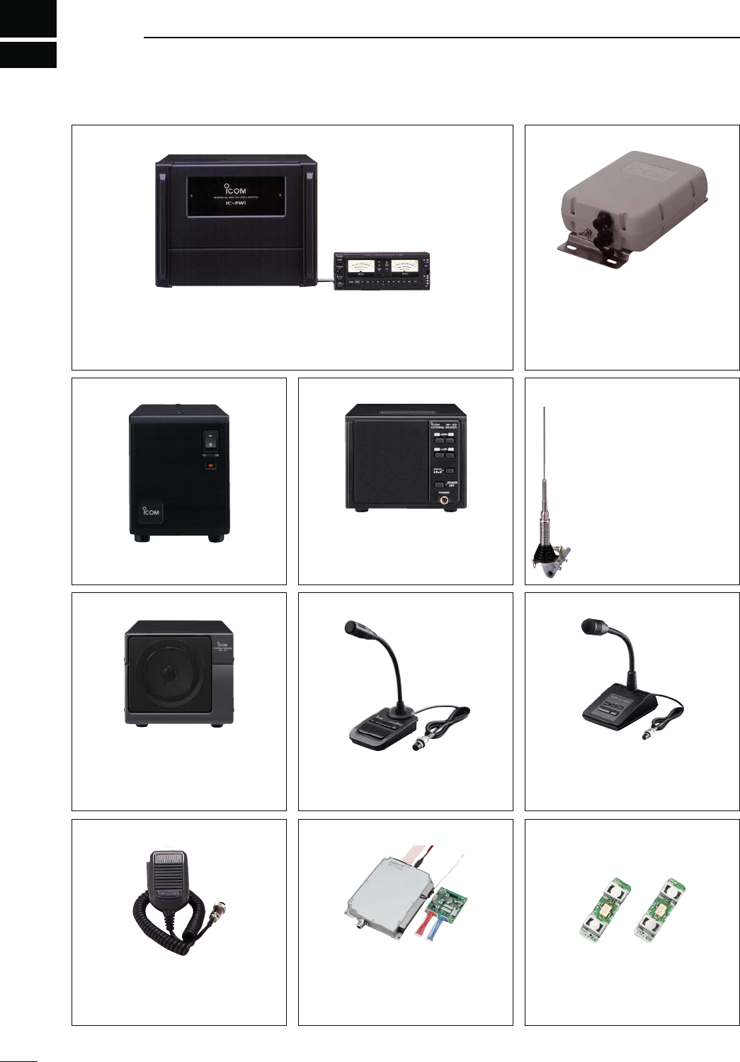
20
199
OPTIONS
AH-4
HF
AUTOMATIC
ANTENNA
TUNER
Specially designed to tune a long wire
antenna for the HF/50 MHz bands,
particularly in portable or mobile oper-
ation. The “PTT tune” function pro-
vides simple operation.
s)NPUTPOWERRATING7
AH-2b ANTENNA ELEMENT
A 2.5 m long antenna ele-
ment for mobile operation
with the AH-4.
s&REQUENCY COVERAGE
7–54 MHz band with the
AH-4
SM-30 DESKTOP MICROPHONE
Unidirectional, electret microphone for
base station operation. Includes a low
cut switch and mic gain control.
SM-50 DESKTOP MICROPHONE
Unidirectional, dynamic microphone for
base station operation. Includes [UP]/
[DOWN] switches, a low cut switch and
mic gain control.
SP-23 EXTERNAL SPEAKER
AUDIO FILTERS HEADPHONE JACK CAN
connect to 2 transceivers.
s)NPUTIMPEDANCEø
s-AXINPUTPOWER7
HM-36 HAND MICROPHONE
Hand microphone equipped with [UP]/
[DOWN] switches.
The same as that attached with the
transceiver.
IC-PW1/EURO HF/50 MHz ALL BAND 1 kW LINEAR AMPLIFIER
Full-duty 1 kW linear amplifier including an automatic antenna tuner. Has auto-
matic tuning and band selection capability. Full break-in (QSK) operation is possi-
ble. The amplifier/power supply unit and the remote control unit can be separated.
The optional OPC-599 ADAPTER CABLE is required for connection.
PS-126 DC POWER SUPPLY
s/UTPUTVOLTAGE6$#
s-AXOUTPUTCURRENT!
UX-9100 1200 MHz BAND UNIT
Allows you additional all mode oper-
ation on the 1200 MHz frequency
band.
FL-430 1ST IF FILTER (6 kHz)
FL-431 1ST IF FILTER (3 kHz)
(Both filters are for HF/50 MHz Band)
The roofing filters reduce interfer-
ence from strong nearby signals.
SP-21 EXTERNAL SPEAKER
Designed for base station operation.
s)NPUTIMPEDANCEø
s-AXINPUTPOWER7

200
20
OPTIONS
20
CT-17 CI-V LEVEL CONVERTER UNIT
For remote transceiver control using a
personal computer equipped with an
23# PORT 9OU CAN CHANGE FRE-
quencies, operating mode, memory
channels, etc., via your computer.
s AG-25
WEATHER
-
PROOF
PREAMPLIFIER
(for 144 MHz Band)
s AG-35
WEATHER
-
PROOF
PREAMPLIFIER
(for 430 MHz Band)
External all-weather, mast mounting preamplifiers for com-
pensating for coaxial cable loss.
s AG-2400 DOWN CONVERTER UNIT
All-weather, satellite down converter with superior NF and
gain.
Input frequency : 2400–2402 MHz
Output frequency : 144–146 MHz
Conversion gain : More than 25 dB
Total NF : Less than 1.5 dB
s OPC-1529R DATA COMMUNICATION CABLE
(RS-232C type)
Allows low-speed data communication in the DV mode, and
receiving a GPS data from a third-party GPS receiver.
s OPC-599 ADAPTER CABLE
13-pin, ACC connector to 7-pin + 8-pin ACC connector.
s-" CARRYING HANDLE
Convenient when carrying the transceiver.
The same as that attached with the transceiver.
s CS-9100 CLONING SOFTWARE
Use this software to program settings, memory channels
and set mode contents quickly and easily via your PC’s
USB port.
A USB cable is required. (A-B type, purchase separately)
s23"! IP REMOTE CONTROL SOFTWARE
To remotely control radios using the RS-BA1, "%352%
that you comply with your local regulations.
Approved Icom optional equipment is designed for
optimal performance when used with an Icom trans-
ceiver.
Icom is not responsible for the destruction or damage
to an Icom transceiver in the event the Icom trans-
ceiver is used with equipment that is not manufac-
tured or approved by Icom.
21
201
CE
INSTALLATION NOTES
For amateur base station installations it is recom-
mended that the forward clearance in front of the an-
tenna array is calculated relative to the EIRP (Effective
Isotropic Radiated Power). The clearance height below
the antenna array can be determined in most cases
from the RF power at the antenna input terminals.
As different exposure limits have been recommended
for different frequencies, a relative table shows a
guideline for installation considerations.
Below 30 MHz, the recommended limits are specified
in terms of V/m or A/m fields as they are likely to fall
within the near-field region. Similarly, the antennas
may be physically short in terms of electrical length
and that the installation will require some antenna
matching device which can create local, high inten-
sity magnetic fields. Analysis of such MF installations
is best considered in association with published guid-
ance notes such as the FCC OET Bulletin 65 Edition
97-01 and its annexes relative to amateur transmitter
installations.
The EC recommended limits are almost identical to
the FCC specified ‘uncontrolled’ limits and tables exist
that show pre-calculated safe distances for different
antenna types for different frequency bands. Further
information can be found at http://www.arrl.org/.
s4YPICALAMATEURRADIOINSTALLATION
Exposure distance assumes that the predominant ra-
diation pattern is forward and that radiation vertically
downwards is at unity gain (sidelobe suppression is
equal to main lobe gain). This is true of almost every
gain antenna today. Exposed persons are assumed
to be beneath the antenna array and have a typical
height of 1.8 m.
The figures assume the worst case emission of a con-
stant carrier.
For the bands 10 MHz and higher the following power
density limits have been recommended:
10–400 MHz 2 W/sq m
435 MHz 2.2 W/sq m
%)20CLEARANCEHEIGHTSBYFREQUENCYBAND
Watts 10–2 m 70 cm 23 cm
13 cm and above
1 2.1 m 2 m 2 m 2 m
10 2.8 m 2.7 m 2.5 m 2.3 m
25 3.4 m 3.3 m 2.7 m 2.5 m
100 5 m 4.7 m 3.6 m 3.2 m
1000 12 m 11.5 m 7.3 m 6.3 m
&ORWARDCLEARANCE%)20BYFREQUENCYBAND
Watts 10–2 m 70 cm 23 cm
13 cm and above
100 2 m 2 m 1.1 m 0.7 m
1,000 6.5 m 6 m 3.5 m 3 m
10,000 20 m 18 m 11 m 7 m
100,000 65 m 60 m 35 m 29 m
In all cases any possible risk depends on the trans-
mitter being activated for long periods. (actual recom-
mendation limits are specified as an average during 6
minutes) Normally the transmitter is not active for long
periods of time. Some radio licenses will require that a
timer circuit automatically cuts off the transmitter after
1–2 minutes etc.
Similarly some modes of transmission, SSB, CW, AM
etc. have a lower ‘average’ output power and the as-
sessed risk is even lower.
Versions of the IC-9100 which display the
“CE” symbol on the serial number label,
comply with the essential requirements of
the European Radio and Telecommunica-
tion Terminal Directive 1999/5/EC.
This warning symbol indicates that this
equipment operates in non-harmonised
frequency bands and/or may be subject to
licensing conditions in the country of use.
Be sure to check that you have the correct
version of this radio or the correct program-
ming of this radio, to comply with national
licensing requirement.
s,ISTOF#OUNTRYCODES)3/
#OUNTRY Codes#OUNTRY Codes
1
2
3
4
5
6
7
8
9
10
11
12
13
14
15
16
17
Austria
Belgium
Bulgaria
Croatia
Czech Republic
Cyprus
Denmark
Estonia
Finland
France
Germany
Greece
Hungary
Iceland
Ireland
Italy
Latvia
AT
BE
BG
HR
CZ
#9
DK
EE
FI
FR
DE
GR
HU
IS
IE
IT
LV
18
19
20
21
22
23
24
25
26
27
28
29
30
31
32
33
Liechtenstein
Lithuania
Luxembourg
Malta
Netherlands
Norway
Poland
Portugal
Romania
Slovakia
Slovenia
Spain
Sweden
Switzerland
Turkey
United Kingdom
LI
LT
LU
MT
NL
NO
PL
PT
RO
SK
SI
ES
SE
CH
TR
GB

202
21
CE
21
DECLARATION
OF CONFORMITY
We Icom Inc. Japan
1-1-32, Kamiminami, Hirano-ku
Osaka 547-0003, Japan
Kind of equipment:
Type-designation:
Signature
Authorized representative name
Place and date of issue
Version (where applicable): Y. Furukawa
General Manager
Icom (Europe) GmbH
Communication Equipment
Auf der Krautweide 24,
65812 Bad Soden am Taunus,
Germany
HF/VHF/UHF TRANSCEIVER
iC-
9100
11th Jan.
2011Bad Soden
Declare on our sole responsibility that this equipment complies with the
essential requirements of the Radio and Telecommunications Terminal
Equipment Directive, 1999/5/EC, and that any applicable Essential Test
Suite measurements have been performed.
This compliance is based on conformity with the following harmonised
standards, specifications or documents:
EN 301 489-1 v1.6.1 (September 2005)
EN 301 489-15 v1.2.1 (August 2002)
EN 301 783-2 v1.1.1 (September 2000)
EN 60950-1 2006 A11: 2009
i)
ii)
iii)
iv)
v)
vi)
!BOUT!'!'AND!'PREAMPLIlERS
The use of IC-9100 (#03, #04,#05, #06, #11) in com-
bination with AG-25, AG-35 and/or AG-1200 pream-
plifiers do not comply with the European Harmonised
Standard regulations. Please do not use the IC-910H
with these preamplifiers (AG-25, AG-35 and/or AG-
1200) intended for the US, Asian, Oceanian and Af-
rican markets.
1-1-32 Kamiminami, Hirano-ku, Osaka 547-0003, Japan
A-6871H-1EX
Printed in Japan
© 2011 Icom Inc.
< Intended Country of Use >
AT
FI
IT
PL
GB
RO
BE
FR
LV
PT
IS
TR
CY
DE
LT
SK
LI
HR
CZ
GR
LU
SI
NO
DK
HU
MT
ES
CH
EE
IE
NL
SE
BG
< Intended Country of Use >
AT
FI
IT
PL
GB
RO
BE
FR
LV
PT
IS
TR
CY
DE
LT
SK
LI
HR
CZ
GR
LU
SI
NO
DK
HU
MT
ES
CH
EE
IE
NL
SE
BG
< Intended Country of Use >
AT
FI
IT
PL
GB
RO
BE
FR
LV
PT
IS
TR
CY
DE
LT
SK
LI
HR
CZ
GR
LU
SI
NO
DK
HU
MT
ES
CH
EE
IE
NL
SE
BG
< Intended Country of Use >
AT
FI
IT
PL
GB
RO
BE
FR
LV
PT
IS
TR
CY
DE
LT
SK
LI
HR
CZ
GR
LU
SI
NO
DK
HU
MT
ES
CH
EE
IE
NL
SE
BG
IC-9100 #11
(France)
< Intended Country of Use >
AT
FI
IT
PL
GB
RO
BE
FR
LV
PT
IS
TR
CY
DE
LT
SK
LI
HR
CZ
GR
LU
SI
NO
DK
HU
MT
ES
CH
EE
IE
NL
SE
BG
IC-9100 #03
(Europe)
IC-9100 #04
(Europe-1)
IC-9100 #05
(Italy)
IC-9100 #06
(Spain)