ICOM orporated 318300 HF/VHF/UHF Transceiver User Manual CONFIDENTIAL ShortTerm IC 9100 UserMan
ICOM Incorporated HF/VHF/UHF Transceiver CONFIDENTIAL ShortTerm IC 9100 UserMan
UserManual.wiki
>
ICOM orporated
>
318300 User Manual
>
User Manual 2
Contents
1.
User Manual 1
2.
User Manual 2
User Manual 2
Navigation menu
Upload a User Manual
Namespaces
Wiki Guide
HTML
PDF
Info
Views
User Manual
Discussion / Help
Navigation
![893DV MODE OPERATIONN$IGITALMODEOPERATIONThe IC-9100 can be operated in the digital voice mode, including low-speed data operation, for both transmit and receive. It can also be connected to a GPS re-ceiver* to transmit/receive position data. * Compatible with an RS-232 output/NMEA format/ 4800bps/9600 bpsN #ALLSIGNSETTINGSet the desired h52vh2vh2vANDh-9vcall signs to be used for DV operation, as described below.NOTE: )NTHE$2MODEYOUCANSETONLYh-9vCALLsign in the “CS” screen (Call Sign).q Push [DVsDR] to select the DV mode.w Push [MENU] one or more times to display the “M3” screen (Menu 3). s)NTHE$2MODEPush [MENU] once or twice to select the “D1” screen.e Push [CS](F-1) to display the “CS” screen (Call Sign).s9OUCANPUSH;&=TOTOGGLEBETWEENTHECALLSIGNANDthe name.r Push [Z](F-1) one or more times to display the h52vh2vh2vORh-9vSCREENt Rotate [MAIN DIAL] to select the desired call sign. s UR : “CQCQCQ,” individual station call signs (U01–U99) or destination repeater call signs*1 is selected. s2 9OURACCESSAREAREPEATERSCALLSIGNISSE-lected. s R2 : “NOT USE1”*2 or a link/gateway repeater call sign is selected. s-99OUROWNCALLSIGNSISSELECTED-9n-9 s&IRSTSELECTINGTHECALLSIGNGROUPBYPUSHING;43s'20=or [GRP](F-5)*3 makes it more convenient when “UR,” “R1” or “R2” is displayed. See the right column for de-tails of the repeater call sign group selection.y Push [SET](F-4) to set the selected call sign to be used for DV operation.u Repeat steps r to y to set the other call signs.i Push [Z](F-1) one or more times to return to the “CS” screen.NOTE:9OUCANTOGGLEBETWEENDISPLAYINGTHERE-peater name or the repeater call sign by pushing [NAME](F-4) in the R1 and R2 screens.*1 ‘/’ is displayed in front of the repeater call sign. The repeater call sign with ‘/’ is used for the gateway CQ calling.*2 For an area (local) repeater communication only (Link repeater is not used.)*3 [GRP](F-5) is not used in the DR mode.[CS]/[√] [SET] [MENU] [DV・DR] [MAIN DIAL]CS CD R>CS UR DSETM3CS URCQCQCQJA3YUAMYR1R2NOT USEÚUR URCLRCQCQCQEDT NAME GRPUR URCLRJG3YMKEDT NAME GRPUR U01JG3YMKSET GRPRotate [MAIN DIAL](OWTOSELECTTHEREPEATERCALLSIGNGROUPHold down [TSsGRP] or [GRP](F-5)*3 for 1 second to enter the group selection mode. Then rotate [MAIN DIAL] to select the desired group. After selecting, PUSH;43s'20=OR;'20=&*3 to display the re-peater call signs in the group.Or, you can select the repeater group using the key-pad key.- Only repeaters assigned to groups are selectable.!BOUTTHE4IME/UT4IMERFUNCTIONThe IC-9100 has a Time-Out Timer function for digi-tal repeater operation. The timer limits a continuous transmission to approximately 10 minutes. Warning beeps will sound approximately 30 seconds before time-out and then again immediately before time-out. Be sure to turn ON the function before operating in the digital mode. (p. 162)](https://usermanual.wiki/ICOM-orporated/318300.User-Manual-2/User-Guide-1415350-Page-1.png)
![948DV MODE OPERATION8N2ECEIVINGA$34!2REPEATERWhen the IC-9100 receives a signal from a D-STAR repeater, it receives four call signs: the calling station’s call sign, the called station’s call sign, the R1 repeater call sign (the repeater that receives a signal from the calling station on the uplink frequency), and the R2 re-peater call sign (the repeater that transmits a signal ONTHEDOWNLINKFREQUENCY9OUCANCOPYTHERECEIVEDcall signs into your radio, and reply to the call.Station A Station BRepeater446.000 MHz445.400 MHz 445.400 MHz446.000 MHzUplinkDownlink(Transmit frequency)(Receive frequency)s0RESETTINGq Select the desired frequency band. (p. 35)w Push [VFO/MEMO] to select the VFO mode.e Push [A/B] once or twice to select VFO A.r Set the desired repeater transmit (downlink) fre-quency. (p. 37) s!DJUSTTHEOUTPUTPOWERIFDESIREDPt Push [MENU] to display the “M1” screen (Menu 1).y Hold down [DUP](F-2) for 1 second to turn ON the One-touch repeater function. sh4vANDh$50nvAPPEARs4HEREPEATERRECEIVEUPLINKFREQUENCYAPPEARSATTHEbottom of the function display.u Push [DUP](F-2) once or twice to switch the offset to the desired direction. sh$50nvORh$50vAPPEARSs7HENTHE!UTO2EPEATERFUNCTIONISINUSETHISSELEC-tion is not necessary (Only U.S.A. and Korean versions). (p. 67)i Push [DVsDR] to select the DV mode. (p. 43)s“DV” appears. sh4vDISAPPEARSo When a signal is received, the calling station’s call sign is displayed on the LCD. s)FTHECALLINGSTATIONHASPROGRAMMEDANOTEORMES-sage, it is displayed after the call sign.See the next page to view the received call sign.To reply to the calling station, see page 96.[VFO/MEMO] [A/B] [DV・DR]“T” disappearsAppearsM1DUPAGC AFC TON SCP445.40000M1DUPAGC AFC DSQ SCP445.40000AppearsUplink frequencyAppears](https://usermanual.wiki/ICOM-orporated/318300.User-Manual-2/User-Guide-1415350-Page-2.png)
![958DV MODE OPERATIONN2ECEIVEDCALLSIGNSWhen a call is received in the DV mode, the calling sta-tion and repeater call signs being used can be stored in the received call record. The stored call signs can be displayed in the following manner.Up to 20 calls can be stored.D$ESIREDCALLRECORDDISPLAYq Push [DVsDR] to select the DV mode.w Push [MENU] one or more times to display the “M3” screen (Menu 3). s)NTHE$2MODEPUSH;-%.5=ONCEORTWICETOSELECTthe “D1” screen.e Push [CD](F-2) to display the “CD” screen (Call Re-cord).r Rotate [MAIN DIAL] to select the desired record channel (RX01 to RX20). s(OLDDOWN;#,2=&FORSECONDTOCLEARTHESELECTEDrecord channel.t Push [Z](F-1) one or more times to display the call record. s#!,,%2 4HECALLINGSTATIONSCALLSIGN s !FOURCHARACTERNOTEFROMTHESTATIONthat made the call. s#!,,%$ 4HECALLSIGNOFTHESTATIONTHATWAScalled, or “CQCQCQ.” s28204 4HECALLSIGNOFTHEREPEATERTHECALL-ing station accessed, or the call sign of the gateway repeater the calling station used. s28204 4HE CALL SIGN OF THE REPEATER YOUheard the call on. s-3' !NYRECEIVEDMESSAGEISDISPLAYED After the MSG screen, the date and time infor-mation are displayed. If the received date and time are unknown, the elapsed time after the call was received is displayed (e.g. “(–12:34)”). If the power is turned OFF, then ON, or 48 hours have passed, “– – – – /– – /– – – –:– –” is displayed.y Push [Z](F-1) one or more times to return to the “CD” screen.[√] [CD] [CLR] [MENU] [DV・DR] [MAIN DIAL]CS CD R>CS UR DSETM3CD JG3YMK CQCQCQRX01CLR COPYCDRxRPT1:RxRPT2:COPYÚCDCALLER: JG3YMKCALLED: CQCQCQ/COPYÚCDMSG: REPEATER IS JP3YHH AÚCD2010/10/10 10:10Ú](https://usermanual.wiki/ICOM-orporated/318300.User-Manual-2/User-Guide-1415350-Page-3.png)
![968DV MODE OPERATION8D/NETOUCHREPLYUSINGTHECALLRECORDThe calling station’s call sign, which is stored in the call record, can be used to quickly and easily reply.s&IRSTSETYOUROWNCALLSIGN-9Ps!FTERRECEIVINGACALLq Push [MENU] one or more times to display the “M3” screen (Menu 3). s)NTHE$2MODEPUSH;-%.5=ONCEORTWICETOSELECTthe “D1” screen.w Hold down [R>CS](F-3) for 1 second to set the other station’s call sign.s4HERECEIVEDCALLSIGNISDISPLAYEDWHILEHOLDINGDOWN[R>CS](F-3), and after releasing, two beeps sound.s7HENACALLSIGNHASNOTBEENRECEIVEDCORRECTLYERRORbeeps sound, and no call sign is set.e Push [PTT] on the microphone to reply the call. (or push [TRANSMIT] on the transceiver)r Release [PTT] to receive. (or push [TRANSMIT] again)s3ELECTINGACALLRECORDq Push [MENU] one or more times to display the “M3” screen (Menu 3). s)NTHE$2MODEPUSH;-%.5=ONCEORTWICETOSELECTthe “D1” screen.w While holding down [R>CS](F-3), rotate [MAIN DIAL] to select the desired record channel, then re-lease [R>CS](F-3) to set it.e Push [PTT] on the microphone to reply the call. (or push [TRANSMIT] on the transceiver)r Release [PTT] to receive. (or push [TRANSMIT] again)For your informationWhen you receive a call addressed to your own call sign, the call signs of the calling station and the re-peaters they used can be automatically set for a quick reply. The set call signs are overwritten if another call is received.The following items must be set to “Auto” in the DV Set mode.These functions are not available in the DR mode.sh28#ALL3IGN7RITEvITEMP The calling station’s call sign is automatically set to “UR.”sh282047RITEvITEMP The repeater call signs are automatically set to “R1” and “R2,” if necessary.[R>CS][MAIN DIAL][TRANSMIT]CS CD R>CS UR DSETM3CS CD R>CS UR DSETM3YK/Hold downThe received call sign is displayed while hold-ing down [R>CS](F-3).Important!One-touch call signs are for only temporary use. They are not saved in a call sign memory. Therefore, when another call sign is set, the previous call sign will be over-written.If you want to save the set call sign, see ‘Copying the call record contents into call sign memory’ for details. (p. 98)](https://usermanual.wiki/ICOM-orporated/318300.User-Manual-2/User-Guide-1415350-Page-4.png)
![978DV MODE OPERATIONN#OPYINGTHECALLSIGND#OPYINGTHECALLSIGNMEMORYCONTENTSThe memorized UR call sign can be copied into an-other call sign memory.NOTE: First, make sure that the “Edit Record” item is set to “Auto” or “Select” in the DV Set mode. (p. 119)q Push [DVsDR] to select the DV mode.w Push [MENU] one or more times to display the “M3” screen (Menu 3). s)NTHE$2MODEPush [MENU] once or twice to select the “D1” screen.e Push [CS](F-1) to display the “CS” screen (Call Sign).r Push [Z](F-1) to display the “UR” screen.t Rotate [MAIN DIAL] to select the desired UR call sign channel to be copied. s5TO5CANBESELECTEDy Push [EDT](F-3) to enter the call sign programming mode. s4HESTDIGITOFTHESELECTEDCALLSIGNBLINKSThe displayed contents from step u are different, depending on the “Edit Record” item setting. (p. 119)7HENTHEh%DIT2ECORDvITEM ISSETTOh!utov A blank channel is automatically selected, and the call sign channel’s data, selected in step t above, is displayed. u Edit the displayed call sign as described in page 86. i Push [MENU] to store the edited call sign into the channel. NOTE: If there are no blank channels in the sta-tion call sign memory, “Full” appears instead of the channel number. In this case, follow the steps in ‘When the “Edit record” item is set to “Select”,’ as shown below.7HENthe h%DIT2ECORDvITEMISSETTO h3ELECTv The selected call sign channel’s data is displayed. u Edit the displayed call sign as described in page 86. i Push [MENU] to set. o Rotate [MAIN DIAL] to select the desired call sign channel to store the data in. !0 Hold down [SET](F-5) for 1 second to store or overwrite the edited call sign into the selected channel.[√] [CD] [CLR] [MENU] [DV・DR] [MAIN DIAL]CS CD R>CS UR DSETM3CS URCQCQCQJA3YUAMYR1R2NOT USEÚUR U06JG3YMKDEL SPCUR U01JG3YML(JG3YMK)SETUR U01CLRJG3YMKEDT GRPSETUR U01JG3YMDEL SPCRotate [MAIN DIAL]UR URCLRCQCQCQEDT NAME GRPWhen the “Edit Record” item is set to “Auto.”When the “Edit Record” item is set to “Select.”](https://usermanual.wiki/ICOM-orporated/318300.User-Manual-2/User-Guide-1415350-Page-5.png)
![988DV MODE OPERATION8This is a way to copy the call record data (“CALLER,” “RXRPT1” and “RXRPT2”) into call sign memory “UR” and a repeater all at the same time, or individually.q Push [DVsDR] to select the DV mode.w Push [MENU] one or more times to display the “M3” screen (Menu 3). s)NTHE$2MODEPUSH;-%.5=ONCEORTWICETOSELECTthe “D1” screen.e Push [CD](F-2) to display the “CD” screen (Call Re-cord).r Rotate [MAIN DIAL] to select the desired record channel (RX01 to RX20).t PUSH;#/09=&TOenter the copy item selection mode.CD JG3YMK CQCQCQRX01CLR COPYy Push [Y](F-1) or [Z](F-2) to select the item to be copied. s!,, 4HE#!,,%228204AND28204call signs. s#!,,%24HECALLINGSTATIONSCALLSIGN s282044HECALLSIGNOFTHEREPEATERTHECALL-ing station accessed, or the call sign of the gateway repeater the calling station used. s282044HECALLSIGNOFTHEREPEATERYOURHEARDthe call on.CALLER: JG3YMKÚAUTO SELÙCOPYThe options in step u are different, depending on your selection in step y.7HENhALLvISSELECTEDINSTEPy: u Select the desired copy destination. s,)34 (OLDDOWN;,)34=&FORSECONDto automatically search a blank call sign memory channel, then copy the call signs of CALLER, RXRPT1 and RXRPT2 into the channel. s#522 (OLDDOWN;#522=&FORSECONDto copy the call signs of CALLER, RXRPT1 and RXRPT2 into the cur-rent “UR,” “R1” and “R2” memory.COPYALLÚLIST CURRÙ7HENhCALLERvISSELECTEDINSTEPy: u Select the desired copy destination s!54/ (OLDDOWN;!54/=&FORSECONDto automatically search for a blank call sign memory channel, and copy the selected call sign into the de-tected one. s3%, 0USH;3%,=&TOENTERTHECALLSIGNmemory channel selection mode. Rotate [MAIN DIAL] to select the de-sired channel to be pasted. s4HECONTENTSOFTHESELECTEDCHAN-nel is displayed in parentheses. Holzd down [SET](F-5) for 1 second to paste the calling station’s call sign into the selected channel. If a call sign has already been programmed, the selected channel will be overwrit-ten.CALLER: JG3YMKÚAUTO SELÙCOPYUR U01(JG3YMK)SETCALLER: JG3YMKWhen “SEL” is selected, memory channel num-ber and call sign blink.7HENhRXRPT1vORhRXRPT2vISSELECTEDINSTEPy: u Hold down [RP-L](F-5) to copy the repeater call sign into the repeater list “R1” or “R2.”COPYRxRPT1:ÚRP–LÙi After copying has been completed, transceiver au-tomatically returns to the “CD” screen.D#OPYINGTHECALLRECORDCONTENTSINTOCALLSIGNMEMORY[√] [CD] [CLR] [MENU] [DV・DR] [MAIN DIAL]Push](https://usermanual.wiki/ICOM-orporated/318300.User-Manual-2/User-Guide-1415350-Page-6.png)
![998DV MODE OPERATIONDR (D-STAR Repeater) mode is used for D-STAR repeater operation. In this mode, you can select the pre-programmed repeaters and UR call sign by using [MAIN DIAL].s$2MODEOPERATIONmOWCHARTs2EPEATERSETTINGSCANBESTOREDINTOAREPEATERMEMORYchannel (Repeater list). N $2$34!22EPEATERMODEOPERATION3TEP2SELECTIONSelect your access repeater.- The Access repeater scan is useful to find a repeater.3TEP52CALLSIGNSELECTIONSelect your destination call sign#ALLING#1Through an access repeater : CQCQCQThrough a zone link repeater or gateway repeater : Zone link repeater or Gateway repeater name#ALLINGASPECIlCSTATION3TEP2SELECTIONSelect a zone link or gateway repeater. If you make a call through an access repeater, select “NOT USE1.”Through an access repeater : NOT USE1Through a zone link repeater : Zone link repeater nameThrough a gateway repeater : Gateway repeater namePush PTT to transmit, release to receive.Access/Area repeater (R1) selectionUR call sign (CQ) selectionUR call sign (specific station) selectionR2 (destination repeater) selectionGRP3D1RH RANO4CS CD R>CS UR DSETCQCS CD R>CS UR DSETD1URCQCQCQURCS CD R>CS UR DSETD1URJG3YMKCS CD R>CS UR DSETD1RNARA4D#OMMUNICATION&ORMs,OCALAREACALL(pp. 101, 103)To call a station through your local area (access) re-peater.s:ONECALL(pp. 102, 104)To call a station through your local area (access) re-peater and a link repeater in the same zone.s'ATEWAYCALL(pp. 102, 104)To call a station through your local area (access) re-peater, gateway repeater and your destination repeater by accessing the internet.NOTE: s Programming the repeater list is required for DR mode operation. (pp. 89 to 92)s9OUCANNOTMAKEAN)NTERNETCALLIFTHESELECTEDrepeater (R2) has no gateway call sign.s While operating voice communication or low-speed data communication via the internet net-work, some packets may be lost due to network error (poor data throughput performance). In such a case, the transceiver displays “ ” on the display to indicate Packet Loss has occurred.](https://usermanual.wiki/ICOM-orporated/318300.User-Manual-2/User-Guide-1415350-Page-7.png)
![1008DV MODE OPERATION8s!CCESSREPEATERSCAN’STARGETSETTING9OUCANSELECTTHEDESIREDREPEATERSASASCANTARGET, for faster selection and scanning.Non-selected repeaters are skipped during scanning.s When a repeater is specified as a non-scan target, its “R1USE” setting is automatically set to NO. In this case, the repeater cannot be selected as the access repeater. (p. 90)q In the DR mode, push [MENU] one or more times to display the “D2” screen.w Rotate [MAIN DIAL] to select the desired access repeater. s&IRSTSELECTINGTHE REPEATERCALLSIGN GROUPMAKESITmore convenient, if you have programmed repeaters into Groups. See the description in page 93 for details of the repeater call sign group selection.e Hold down [SEL](F-2) for 1 second to set the select setting to ON.sh3%,vAPPEARSr Push [SEL](F-2) to set the select setting to OFF.sh3%,vDISAPPEARSt Push [MENU] to return to the “D2” screen.D!CCESSREPEATERSCANThe Access repeater scan is useful to find a repeater.For rapidly find, the Access repeater scan skips the repeaters which are not specified as a scan target.9OUCANSELECTTHEDESIREDREPEATERSASASCANTARGETSee page 90 or ‘Access repeater scan’s target setting’ as described below.q Hold down [DVsDR] for 1 second to select the DR mode.s4HE$6MODEISAUTOMATICALLYSELECTEDsThe access repeater selection screen is displayed. - Only the repeaters, specified as a scan target are dis-played.w Push [MENU] one or more time to display the “D2” screen.e Push [SCAN](F-1) to start the Access repeater scan.s4HE-(ZANDK(ZDECIMALPOINTSANDh ” blink while scanning. s(OLDDOWN;3#!.=&FORSECONDTOENTERTHE3CANset mode. Push [MENU] to exit the Scan set mode. - If “Up/Down” is selected as the “MAIN DIAL (SCAN)” option in the Scan Set mode, rotating [MAIN DIAL] changes the scanning direction. (p. 147) s4HESCANPAUSESWHENASIGNALISRECEIVEDr Push [SCAN](F-1) to cancel the scan.[D[MAIN DIAL][D[MENU][SEL] GRPSCAN SEL A FC DSQ TCOND2GRP3SCAN SEL A FC DSQ TCOND2RHIRANO4GRP1SCAN SEL A FC DSQ TCOND2RFUJ SW4GRP1SELD2FU ISW4SELGRP1SELD2FU ISW4When the select setting is OFF.GRP1SCAN SEL A FC DSQ TCOND2RHAMACH 3Rotate [MAIN DIAL]Hold downPushWhile Access repeater scanning](https://usermanual.wiki/ICOM-orporated/318300.User-Manual-2/User-Guide-1415350-Page-8.png)
![1018DV MODE OPERATIONN#ALLING#1&IRSTPROGRAMA-9CALLSIGNINSTEPq.Next program the repeater list (p. 89). After that, follow this guide to access a D-STAR repeater.The optional CS-9100* cloning software is helpful for programming call signs and programming the repeater list.*Cloning cable is required.q3ETYOUROWNCALLSIGN-9(p. 85)w Hold down [DVsDR] for 1 second to select the DR mode.sThe last used access repeater is displayed. - If the displayed frequency band on the SUB Band is the same as that of the last used access repeater, se-lecting the DR mode on the MAIN Band will automati-cally move the frequency band on the SUB Band to the Main Band display, and turn OFF the SUB Band display.e Rotate [MAIN DIAL] to select the desired access repeater. s/NLYTHEREPEATERS, whose “R1USE” setting is set to 9%3OR!CCESSREPEATERSCANTARGETS are displayed. (pp. 90, 100) s&IRSTSELECTINGTHE REPEATERCALLSIGN GROUPMAKESITmore convenient, if you have programmed repeaters into Groups. (p. 93) s!CCESSREPEATERSCANCANBEUSEDFORTHESELECTION (p. 100)r Push [UR](F-4) to enter the UR call sign selection mode.Steps t through u differ, depending on the com-munication form.CS CD R>CS UR DSETD1GRP3RNARA43CS CD R>CS UR DSETD1URUCQCQCQ[MAIN DIAL][DAccess repeater selection screenUR call sign selection screenRepeater group selection screenAppearsGRP3CS CD R>CS UR DSETD1RNARA4Appear[TRANSMIT] [[MAIN DIAL]MAIN Band TX/RX indicator-AKINGA#1CALLTHROUGHYOURLOCALAREAACCESSREPEATER,OCAL!REA#1My call sign:JA3YUACQAreaZoneRepeater q: NARA43 (JP3YHL)q w e rt Rotate [MAIN DIAL] to select “CQCQCQ.” s&IRSTSELECTINGACALLSIGNGROUPAS“CQCQCQ” by push-ING;43s'20=MAKESITMORECONVENIENTy Push [PTT] on the microphone to transmit. (or [TRANSMIT] on the transceiver) s4HE-!)."AND4828INDICATORLIGHTSREDu Release [PTT] to receive. (or push [TRANSMIT] again)](https://usermanual.wiki/ICOM-orporated/318300.User-Manual-2/User-Guide-1415350-Page-9.png)
![1028DV MODE OPERATION8-AKINGA:ONE#1'ATEWAY#1CALLNOTE: The settings are the same between Zone CQ and Gateway CQ call.CS CD R>CS UR DSETD1GRP3UIKOMA 3Repeater selection screenAppear[TRANSMIT] [[MAIN DIAL]MAIN Band TX/RX indicatorThe selected channel number blinks.When a blank channel is selected.()1chARAS CQCQMWDV446.00000( ) 5chMW—————————.—————D3TORINGTHESETDATA9OU CANSAVETHE TEMPORARYSETTINGINTHE FOLLOWINGmanner.q After setting, push [MW] to enter the memory select write mode, then rotate [MAIN DIAL] or [M-CH] to select the desired Memory channel, Call channel or Program scan edge channel.w Hold down [MW] again for 1 second to store the set-ting.t Rotate [MAIN DIAL] to select a desired destination repeater. s&IRSTSELECTINGTHE REPEATERCALLSIGN GROUPMAKESITmore convenient, if you have programmed repeaters into Groups. (p. 93)y Push [PTT] on the microphone to transmit. (or [TRANSMIT] on the transceiver) s4HE-!)."AND4828INDICATORLIGHTSREDu Release [PTT] to receive. (or push [TRANSMIT] again)s#ALLING#1THROUGHALINKREPEATERINTHESAMEZONE:ONE#1My call sign:JA3YUARepeater q : NARA43 (JP3YHL)Repeater r : IKOMA43 (JP3YHJ)CQq w e rAreaZones#ALLING#1THROUGHAGATEWAYREPEATER'ATEWAY#1Repeater e : Repeater y : CQq w e rt y u iMY call sign:JA3YUAGatewayGatewayAreaZone AZone BHIRANO43(JP3YHH)IcomUSA(N7IH)](https://usermanual.wiki/ICOM-orporated/318300.User-Manual-2/User-Guide-1415350-Page-10.png)
![1038DV MODE OPERATIONN#ALLINGASPECIlCSTATIONThis section describes how to call a specific station using the DR mode.When the Link repeater (R2) is set to “GW,” the des-ignated gateway repeater is automatically set as the Link repeater, and you can make a call to a specific station through the internet.q Set your own call sign.w Hold down [DVsDR] for 1 second to select the DR mode.sThe last used access repeater is displayed. - If the displayed frequency band on the SUB Band is the same as that of the last used access repeater, se-lecting the DR mode on the MAIN Band will automati-cally move the frequency band on the SUB Band to the Main Band display, and turn OFF the SUB Band display.e Rotate [MAIN DIAL] to select the desired access repeater. s/NLYTHEREPEATERS, whose “R1USE” setting is set to 9%3OR!CCESSREPEATERSCANTARGETS are displayed. (pp. 90, 100)r Push [UR](F-4) to enter the UR call sign selection mode.t Rotate [MAIN DIAL] to select a individual station call sign. s&IRST SELECTING THE station call sign memory groups (U01–U99)BYPUSHING;43s'20=MAKESITMORECONVE-nient.y Hold down [UR](F-4) for 1 second to enter the Link/Gateway repeater (R2) selection mode.-AKINGACALLTOANINDIVIDUALSTATIONTHROUGHYOURLOCALAREAACCESSREPEATER,OCAL!REACALLMY call sign:JA3YUAStation call sign:JG3YMKRepeater q : NARA43 (JP3YHL)q w e rAreaZoneu Rotate [MAIN DIAL] to select “NOT USE1.”i Push [UR](F-4) to exit the Link repeater (R2) selec-tion mode.o Push [PTT] on the microphone to transmit. (or [TRANSMIT] on the transceiver) s4HE-!)."AND4828INDICATORLIGHTSRED!0 Release [PTT] to receive. (or push [TRANSMIT] again)s!FTERTRANSMITTINGPUSH;-7=TOENTERTHEMEMORYSE-lect write mode. (p. 102)[MAIN DIAL][D]NOT USE1CS CD R>CS UR DSETD1R2:NOT US [TRANSMIT] [UR] [MW][MAIN DIAL]MAIN Band TX/RX indicator](https://usermanual.wiki/ICOM-orporated/318300.User-Manual-2/User-Guide-1415350-Page-11.png)
![1048DV MODE OPERATION8Link repeater in the same zoneCS CD R>CS UR DSETD1R2IKOMA 4Gateway repeater “GW”CS CD R>CS UR DSETD1R2GW-AKING A CALL TO AN INDIVIDUAL STATION THROUGH ALINKREPEATERINTHESAMEZONE:ONECALLMY call sign:JA3YUAStation call sign:JG3YMKRepeater q : NARA43 (JP3YHL)Repeater r : IKOMA-43 (JP3YHJ)q w e rAreaZoneu Rotate [MAIN DIAL] to select the link repeater in the same zone. s/NLYREPEATERSWITHTHESAME GATEWAY REPEATERAP-pear.i Push [UR](F-4) to exit the selection mode.i Push [PTT] on the microphone to transmit. (or [TRANSMIT] on the transceiver) s4HE-!)."AND4828INDICATORLIGHTSRED!0 Release [PTT] to receive. (or push [TRANSMIT] again)s!FTERTRANSMITTINGPUSH;-7=TOENTERTHEMEMORYSE-lect write mode. (p. 102)-AKING A CALL TO AN INDIVIDUAL STATIONTHROUGH AGATEWAYREPEATER'ATEWAYCALLRepeater e : Repeater y : HIRANO43(JP3YHH G)HAMA43(JP1YIU G)GatewayGatewayAreaZone AZone Bq w e rt y u iMY call sign:JA3YUAStation call sign:JM1ZLKu Rotate [MAIN DIAL] to select “GW.” s4HEPREPROGRAMMEDGATEWAYREPEATERISSETAS2 s/NLYREPEATERSWITHTHESAME GATEWAY REPEATERAP-pear.i Push [UR](F-4) to exit the Link repeater (R2) selec-tion mode.o Push [PTT] on the microphone to transmit. (or [TRANSMIT] on the transceiver) s4HE-!)."AND4828INDICATORLIGHTSRED!0 Release [PTT] to receive. (or push [TRANSMIT] again)s!FTERTRANSMITTINGPUSH;-7=TOENTERTHEMEMORYSE-lect write mode. (p. 102)[TRANSMIT] [UR] [MW][MAIN DIAL]MAIN Band TX/RX indicatorNOTE: If other station has accessed a repeater at least once, the D-STAR system will automatically connect to the last repeater the station accessed, even if you don’t know where the station is. So it is no need to select the destination repeater.[TRANSMIT] [UR] [MW][MAIN DIAL]MAIN Band TX/RX indicator](https://usermanual.wiki/ICOM-orporated/318300.User-Manual-2/User-Guide-1415350-Page-12.png)
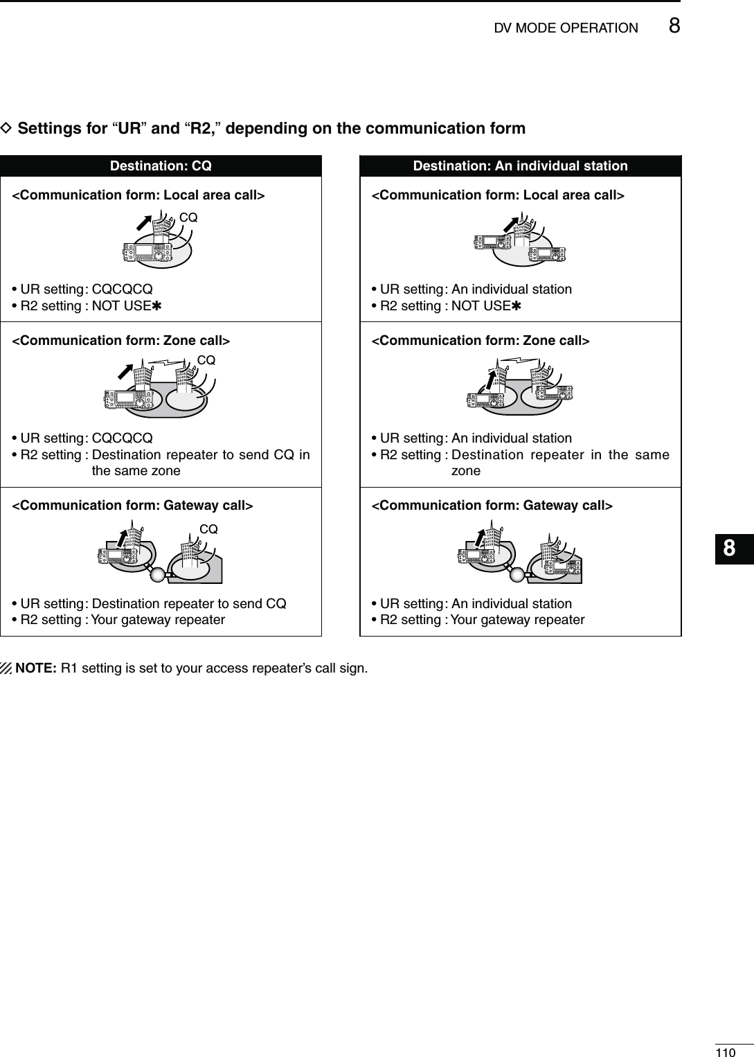
![1058DV MODE OPERATIONN Calling a specific station (Continued)D#ONlRMINGTHESETTINGq In the DR mode, push [MENU] one or more times to display the “D1” screen.w Push [CS](F-1) to display the “CS” screen (Call Sign).e Push [Z](F-1) one or more times to sequentially DISPLAYTHEh52vh2vh2vORh-9vTOCONlRMTHEcurrent call sign setting.NOTE: In the DR mode, you can change only the h-9vCALLSIGNINTHE“CS” screen (Call Sign).[CS]/[Z][MENU]CS URJG3YMKJA3YUAMYR1JP3YHLR2JP3YHJÚGRP3D1RNA A4CS CD R>CS UR DSETD3ETTINGSFOR“UR”AND“2”DEPENDINGONTHECOMMUNICATIONFORM$ESTINATION#1 $ESTINATION!NINDIVIDUALSTATION#OMMUNICATIONFORM,OCALAREACALLCQs52SETTING#1#1#1s2SETTING.!#OMMUNICATIONFORM,OCALAREACALLs52SETTING!NINDIVIDUALSTATIONs2SETTING./453%1#OMMUNICATIONFORM:ONECALLCQs52SETTING$ESTINATIONREPEATERTOSEND#1INthe same zones2SETTING.!#OMMUNICATIONFORM:ONECALLs52SETTING!NINDIVIDUALSTATIONs2SETTING$ESTINATION REPEATER IN THE SAMEzone#OMMUNICATIONFORM'ATEWAYCALLCQs52SETTING$ESTINATIONREPEATERTOSEND#1s2SETTING.!#OMMUNICATIONFORM'ATEWAYCALLs52SETTING!NINDIVIDUALSTATIONs2SETTING'7NOTE: R1 setting is set to your access repeater’s call sign.](https://usermanual.wiki/ICOM-orporated/318300.User-Manual-2/User-Guide-1415350-Page-13.png)
![1068DV MODE OPERATION8s#ALLING#1MY call sign:JA3YUACQs#ALLINGANINDIVIDUALSTATIONMy call sign:JA3YUAStation call sign:JG3YMK[TRANSMIT]MAIN BandTX/RX indicator[MAIN DIAL][D[MENU][VFO/MEMO][UR]/[SET]CS CD R>CS UR DSETM3UR URJG3LUKGRPURCQCQCQSET GRPU––Rotate [MAIN DIAL]s7HENCALLING#1q Select the desired frequency band. (p. 35)w Push [VFO/MEMO] to select the VFO mode.e Push [DVsDR] to select the DV mode.r Set the desired frequency. (p. 37) s3ELECTTHEOUTPUTPOWERIFDESIREDP sWhen the duplex operation is selected, push [MENU] one or more times to display the “M1” screen (Menu 1) and push [DUP](F-2) one or more times to turn it OFF.t Push [MENU] twice to display the “M3” screen (Menu 3).y3ETYOUROWNCALLSIGNASTHECURRENT-9CALLSIGN(p. 85)u Push [UR](F-4) to enter the UR call sign selection mode.i Rotate [MAIN DIAL] to select UR call sign. s&IRSTSELECTINGTHECALLSIGNMEMORYGROUPSBYPUSHING;43s'20=OR;'20=&MAKESITMORECONVENIENT s When calling CQ : Select “CQCQCQ” s When calling an individual station : Select the station’s call signo Push [SET](F-4) to return to the “M3” screen (Menu 3).!0 Push [PTT] on the microphone to transmit. (or [TRANSMIT] on the transceiver) s4HE-!)."AND4828INDICATORLIGHTSRED!1 Release [PTT] to receive. (or push [TRANSMIT] again) s)FANOTHERSTATIONREPLIESITSCALLSIGNWILLBERECEIVED s2ECEIVEDCALLSIGNSCANBEAUTOMATICALLYSTOREDINTOTHEreceived call record. See page 95 for details.s!FTERTRANSMITTINGROTATE;-#(=TOSELECTAMEMORy channel, then hold down [MW] for 1 second to save this temporary programmed data into the channel.NOTE: The digital mode is vastly different than the FM mode. One of the differences is that changing the squelch setting in the digital mode will not open it to hear the hiss of “white noise,” like it does in the FM mode. It is only activated for digital squelch func-tions such as CSQL (Digital code squelch) or DSQL (Digital call sign squelch).N 3IMPLEXOPERATIONUSINGTHE6&/D-AKINGASIMPLEX#1CALLORACALLTOANINDIVIDUALSTATION](https://usermanual.wiki/ICOM-orporated/318300.User-Manual-2/User-Guide-1415350-Page-14.png)
![1078DV MODE OPERATIONs#ALLING#1My call sign:JA3YUACQAreaZoneRepeater q: JP3YHLq w e rs#ALLINGANINDIVIDUALSTATIONMy call sign:JA3YUAStation call sign:JG3YMKRepeater q : JP3YHLq w e rAreaZoneN 2EPEATEROPERATIONUSINGTHE6&/D-AKINGA#1CALLORACALLTOANINDIVIDUALSTATIONTHROUGHYOURLOCALAREAACCESSRE-PEATER,OCAL!REACALL[TRANSMIT]MAIN BandTX/RX indicator[MAIN DIAL][D[MENU][VFO/MEMO][SET][Z] [GRP]UR URCLRJG3YMKEDT NAME GRPR1 R1CLRJP3YHLEDT NAME GRPUR U01CQCQCQSET GRPRotate [MAIN DIAL]R2 R2CLR EDT NAME GRPMY MY1CLRJA3YUA ⁄EDT NAMEUR URCLRCQCQCQEDT NAME GRPs7HENCALLING#1THROUGHASINGLEREPEATERq Select the desired frequency band. (p. 35)w Push [VFO/MEMO] to select the VFO mode.e Push [DVsDR] to select the DV mode.r Set the repeater’s transmit frequency, duplex direc-tion and offset. (pp. 37, 65, 163)t Push [MENU] one or more times to display the “M3” screen (Menu 3).y Push [CS](F-1) to display the “CS” screen (Call Sign).u Push [Z](F-1) to display the “UR” screen, and rotate [MAIN DIAL] to select UR call sign, then push [SET](F-4). s&IRSTSELECTINGTHECALLSIGNMEMORYGROUPSBYPUSHING;43s'20=OR;'20=&MAKESITMORECONVENIENT s When calling CQ : Select “CQCQCQ” s When calling an individual station : Select the station’s call signi Push [Z](F-1) to display the “R1” screen, and rotate [MAIN DIAL] to select the access repeater call sign, then push [SET](F-4). s&IRSTSELECTINGTHE REPEATERCALLSIGN GROUPMAKESITmore convenient, if you have programmed repeaters into Groups. (p. 93) s0USH;.!-%=&TOTOGGLETHECALLSIGNANDREPEATERname display, if the name has been programmed.o Push [Z](F-1) to display the “R2” screen, and rotate [MAIN DIAL] to set R2 to “NOT USE1,” then push [SET](F-4).!0 Push [Z](F-1) TODISPLAYh-9vANDSETYOUROWNCALLsign if necessary, then push [SET](F-4).!1 Push [PTT] on the microphone to transmit. (or [TRANSMIT] on the transceiver) s4HE-!)."AND4828INDICATORLIGHTSRED!2 Release [PTT] to receive. (or push [TRANSMIT] again) s)FANOTHERSTATIONSREPLIESITSCALLSIGNWILLBESTOREDINthe receive log. s2ECEIVEDCALLSIGNSCANBEAUTOMATICALLYSTOREDINTOTHEreceived call record. See page 95 for details.s!FTERTRANSMITTINGROTATE;-#(=TOSELECTAMEMORYchannel, then hold down [MW] for 1 second to save this temporary programmed data into the channel.](https://usermanual.wiki/ICOM-orporated/318300.User-Manual-2/User-Guide-1415350-Page-15.png)
![1088DV MODE OPERATION8s#ALLING#1My call sign:JA3YUARepeater q : JP3YHLRepeater r : JP3YHJCQq w e rAreaZones#ALLINGANINDIVIDUALSTATIONMy call sign:JA3YUAStation call sign:JG3YMKRepeater q : JP3YHLRepeater r : JP3YHJq w e rAreaZone[TRANSMIT]MAIN BandTX/RX indicator[MAIN DIAL][D[MENU][VFO/MEMO][SET][Z] [GRP]UR URCLRJG3YMKEDT NAME GRPR1 R1CLRJP3YHLEDT NAME GRPUR U01CQCQCQSET GRPRotate [MAIN DIAL]R2 R2CLRJP3YHJEDT NAME GRPMY MY1CLRJA3YUA ⁄EDT NAMEUR URCLRCQCQCQEDT NAME GRPs#ALLING#1 INTHESAMEZONE:ONE#1q Select the desired frequency band. (p. 35)w Push [VFO/MEMO] to select the VFO mode.e Push [DVsDR] to select the DV mode.r Set the repeater’s transmit frequency, duplex direc-tion and offset. (pp. 37, 65, 163)t Push [MENU] one or more times to display the “M3” screen (Menu 3).y Push [CS](F-1) to display the “CS” screen (Call Sign).u Push [Z](F-1) to display the “UR” screen, and rotate [MAIN DIAL] to select UR call sign, then push [SET](F-4). s&IRSTSELECTINGTHECALLSIGNMEMORYGROUPSBYPUSHING;43s'20=OR;'20=&MAKESITMORECONVENIENT s When calling CQ : Select “CQCQCQ” s When calling an individual station : Select the station’s call signi Push [Z](F-1) to display the “R1” screen, and rotate [MAIN DIAL] to select the access repeater call sign, then push [SET](F-4). s&IRSTSELECTINGTHE REPEATERCALLSIGN GROUPMAKESITmore convenient, if you have programmed repeaters into Groups. (p. 93) s0USH;.!-%=&TOTOGGLETHECALLSIGNANDREPEATERname display, if the name has been programmed.o Push [Z](F-1) to display the “R2” screen, and rotate [MAIN DIAL] to select the link repeater call sign in the same zone, then push [SET](F-4).!0 Push [Z](F-1) TODISPLAYh-9vANDSETYOUROWNCALLsign if necessary, then push [SET](F-4).!1 Push [PTT] on the microphone to transmit. (or [TRANSMIT] on the transceiver) s4HE-!)."AND4828INDICATORLIGHTSRED!2 Release [PTT] to receive. (or push [TRANSMIT] again) s)FANOTHERSTATIONSREPLIESITSCALLSIGNWILLBESTOREDINthe receive log. s2ECEIVEDCALLSIGNSCANBEAUTOMATICALLYSTOREDINTOTHEreceived call record. See page 95 for details.s!FTERTRANSMITTINGROTATE;-#(=TOSELECTAMEMORYchannel, then hold down [MW] for 1 second to save this temporary programmed data into the channel.D-AKINGA#1CALLORACALLTOANINDIVIDUALSTATIONTHROUGHALINKREPEATERINTHESAMEZONE:ONECALL](https://usermanual.wiki/ICOM-orporated/318300.User-Manual-2/User-Guide-1415350-Page-16.png)
![1098DV MODE OPERATIONq Select the desired frequency band. (p. 35)w Push [VFO/MEMO] to select the VFO mode.e Push [DVsDR] to select the DV mode.r Set the repeater’s transmit frequency, duplex direc-tion and offset. (pp. 37, 65, 163)t Push [MENU] one or more times to display the “M3” screen (Menu 3).y Push [CS](F-1) to display the “CS” screen (Call Sign).u Push [Z](F-1) to display the “UR” screen, and ro-tate [MAIN DIAL] to select UR call sign, then push [SET](F-4). s&IRSTSELECTINGTHEcall sign memory groups by pushing ;43s'20=OR;'20=&MAKESITMORECONVENIENT s When calling CQ : Select a link repeater call sign for sending CQ s When calling an individual station : Select the station’s call signi Push [Z](F-1) to display the “R1” screen, and rotate [MAIN DIAL] to select the access repeater call sign, then push [SET](F-4). s&IRSTSELECTINGTHE REPEATERCALLSIGN GROUPMAKESITmore convenient, if you have programmed repeaters into Groups. (p. 93) s0USH;.!-%=&TOTOGGLETHECALLSIGNANDREPEATERname display.o Push [Z](F-1) to display “R2,” and rotate [MAIN DIAL] to select your gateway repeater call sign, then push [SET](F-4).!0 Push [Z](F-1) TODISPLAYh-9vANDSETYOUROWNCALLsign if necessary, then push [SET](F-4).!1 Push [PTT] on the microphone to transmit. (or [TRANSMIT] on the transceiver) s4HE-!)."AND4828INDICATORLIGHTSRED!2 Release [PTT] to receive. (or push [TRANSMIT] again) s)FANOTHERSTATIONSREPLIESITSCALLSIGNWILLBESTOREDINthe receive log. s2ECEIVEDCALLSIGNSCANBEAUTOMATICALLYSTOREDINTOTHEreceived call record. See page 95 for details.s!FTERTRANSMITTINGROTATE;-#(=TOSELECTAMEMORYchannel, then hold down [MW] for 1 second to save this temporary programmed data into the channel.[TRANSMIT]MAIN BandTX/RX indicator[MAIN DIAL][D[MENU][VFO/MEMO][SET][Z] [GRP]UR URCLRJG3YMKEDT NAME GRPR1 R1CLRJP3YHLEDT NAME GRPUR GRP1⁄ JP1YIUSET GRPRotate [MAIN DIAL]R2 R2CLRJP3YHH GEDT NAME GRPMY MY1CLRJA3YUA ⁄EDT NAMEUR GRP1CLR⁄ JP1YIUEDT NAME GRPs#ALLING#1 THROUGHTHEGATEWAYs#ALLING#1Repeater q : JP3YHLRepeater e : JP3YHH GRepeater u : JP1YIUCQq w e rt y u iMy call sign:JA3YUAGatewayGatewayAreaZone AZone Bs#ALLINGANINDIVIDUALSTATIONRepeater q : JP3YHLRepeater e : JP3YHH GRepeater u : JP1YIUGatewayGatewayAreaZone AZone Bq w e rt y u iMy call sign:JA3YUAStation call sign: JM1ZLKN Repeater operation in the VFO (Continued)D-AKINGA#1CALLORACALLTOANINDIVIDUALSTATIONTHROUGHGATEWAYREPEATERS'ATEWAYCALL](https://usermanual.wiki/ICOM-orporated/318300.User-Manual-2/User-Guide-1415350-Page-17.png)
![1118DV MODE OPERATIONN-ESSAGEOPERATIOND48MESSAGEPROGRAMMINGThe transceiver has a total of 5 message memories to store short messages to transmit during DV mode operation. Message of up to 20 characters can be pro-grammed for each memory.q In the DV mode, push [MENU] one or more times to display the “M3” screen (Menu 3). s)NTHE$2MODEPush [MENU] once or twice to select the “D1” screen.w Push [DSET](F-5) to display the “DSET” screen.e Push [TXM](F-3) to display the “TXM” screen (Tras-nmit message).r Rotate [MAIN DIAL] to select the desired transmit message channel. s4-TO4-AND/&&ARESELECTABLEt Push [EDT](F-1) to enter the transmit message pro-gramming mode. s!CURSORAPPEARSANDBLINKSy Push [F-1] one or more times to select the desired character type.#HARACTERTYPE 3ELECTABLECHARACTERSABC A to Zabc a to zetc <" ’ ` ^ + – 1b< > ( ) [ ] { } ¦ _ ¯ @u Rotate [MAIN DIAL] to select the first character to input. When inputting numbers or a decimal point, push the appropriate keypad key. s0USH;$%,=&TODELETETHESELECTEDCHARACTERSYM-bol or number. s0USH;30#=&TOINPUTASPACE s7HENALL CHARACTERSHAVEBEENprogrammed, an error beep sounds. If you want to reprogram, push [Ω](F-2) or [≈](F-3) to select a character, then push [DEL](F-4) to delete it.i Push [Ω](F-2) to move the cursor backward, or push [≈](F-3) to move the cursor forward.o Repeat steps y through i to program a message of up to 20 characters.!0 Push [MENU] to save the programmed message.While [SET](F-5) is blinking, push it to set the dis-played channel as the first appearance channel when [TXM](F-3) is pushed in step e.TXMOFFTXMTM1:EDT SETABCTXMTM1:HELLODEL SPC[MAIN DIAL][MENU] [TXM][DSET][EDT]Rotate [MAIN DIAL]ABCTXMTM1:HELLODEL SPCCharacter type display Cursor[][][DEL][SPC] [MAIN DIAL]Number input Character type selections0ROGRAMINGATRANSMITMESSAGEInput a spaceDelete a characterMove cursor forwardsMove cursor backwardsCharacter type selection](https://usermanual.wiki/ICOM-orporated/318300.User-Manual-2/User-Guide-1415350-Page-19.png)
![1128DV MODE OPERATION8D-ESSAGE4RANSMISSION9OUCANSELECTAMESSAGECHANNEL4-n4-TOTURNON the message transmission function. When a mes-sage channel is selected, the transceiver transmits the pre-programmed text message. The default setting is OFF.q Set the operating frequency, call signs and other settings, such as those for repeater operation, as desired.w In the DV mode, push [MENU] one or more times to display the “M3” screen (Menu 3). s)NTHE$2MODEPush [MENU] once or twice to select the “D1” screen.e Push [DSET](F-5) to display the “DSET” screen.r Push [TXM](F-3) to display the “TXM” screen (Transmit message).t Rotate [MAIN DIAL] to select the desired transmit message channel, then push [SET](F-5). s4-TO4-ARESELECTABLEs7HEN/&&ISSELECTEDTHEMESSAGEISNOTTRANSMITTEDy Push [MENU] to return to the “DSET” screen.u Push [PTT] on the microphone to transmit the mes-sage. (or push [TRANSMIT] on the transceiver)s4HEMESSAGEISTRANSMITTEDEACHTIMEYOUPUSH;044=(or [TRANSMIT]).s4HEMESSAGEISAUTOMATICALLYTRANSMITTEDEVERYSEC-onds during continuous transmission. s4HE-!)."AND4828INDICATORLIGHTSREDD28MESSAGEDISPLAYq In the DV mode, push [MENU] one or more times to display the “M3” screen (Menu 3). s)NTHE$2MODEPUSH;-%.5=ONCEORTWICETOSELECTthe “D1” screen.w Push [CD](F-2) to display the “CD” screen (Call Re-cord).e Rotate [MAIN DIAL] to select the desired record channel (RX01 to RX20).r Push [Z](F-1) three times to select “MSG” item. s4HERECEIVEDMESSAGEISDISPLAYEDt Push [Z](F-1) or [MENU] to return to the record channel, selected in step e.NOTE: Up to 20 messages can be stored, but only one message can be stored for each call sign.The oldest message is cleared when 21st message is received.EDTTM1:TXMSET[MAIN DIAL][MENU] [TXM][DSET]/[SET][TRANSMIT]MAIN BandTX/RX indicator For your informationWhen a call with a message is received, the call sign and the message scrolls across the function display.The received call sign and/or message display func-tions can be turned OFF in the DV SET mode, if de-sired.± “RX Message Disp” item (p. 119)± “RX Call Sign Disp” item (p. 119)[MAIN DIAL][MENU][CD][√]CD JG3YMK JA3YUARX01CLR COPYCDMSG: REPEATER IS JP3YHH AÚAfter selecting the record channel, push [Z](F-1) three times.](https://usermanual.wiki/ICOM-orporated/318300.User-Manual-2/User-Guide-1415350-Page-20.png)
![1138DV MODE OPERATIONN $6AUTOMATICDETECTIONWhen a non-digital signal is received during DV mode operation, the “DV” and “FM” icons simultaneously blink. The transceiver automatically selects the FM mode to monitor the signal, if the DV Auto Detect func-tion is turned ON.q In the DV mode, push [MENU] one or more times to display the “M3” screen (Menu 3). s)NTHE$2MODEPush [MENU] once or twice to select the “D1” screen.w Push [DSET](F-5) to display the “DSET” screen.e Push [SET](F-5) to enter the DV Set mode.r Push [Y](F-1) or [Z](F-2) to select “DV Auto De-tect.”t Rotate [MAIN DIAL] to turn ON the DV automatic detect function. sThe operating mode is set to DV if this setting is “OFF.”y Push [MENU] to return to the “DSET” screen.The received FM audio may be distorted when using this function.[MAIN DIAL][MENU][DSET]/[SET][][]BlinkWhile receiving a non-digital signal while in the DV modeN!UTOMATIC2EPLYFUNCTIONWhen a call addressed to own your call sign is re-ceived, the Automatic Reply function automatically re-plies with your call sign.q In the DV mode, push [MENU] one or more times to display the “M3” screen (Menu 3). s)NTHE$2MODEPush [MENU] once or twice to select the “D1” screen.w Push [DSET](F-5) to display the “DSET” screen.e Push [SET](F-5) to enter the DV Set mode.r Push [Y](F-1) or [Z](F-2) to select “Auto Reply.”t Rotate [MAIN DIAL] to turn ON the Automatic reply function.y Push [MENU] to return to the “DSET” screen.NOTE: The Automatic replay function is automati-cally turned OFF, when [PTT] (or [TRANSMIT]) is pushed to transmit.Ù2ÚONSET Auto Reply[MAIN DIAL][MENU][DSET]/[SET][][]When the Automatic reply function is ON.](https://usermanual.wiki/ICOM-orporated/318300.User-Manual-2/User-Guide-1415350-Page-21.png)
![1148DV MODE OPERATION8N$IGITALSQUELCHFUNCTIONSThe digital squelch opens only when receiving a sig-nal addressed to your own call sign, or a signal that INCLUDESAMATCHINGDIGITALCODE9OUCANSILENTLYWAITfor calls from others.NOTE: Use digital code squelch function when com-municating with two or more stations, because the digital call sign squelch function opens only when receiving a signal addressed to your own call sign. Thus the digital call sign squelch function can be used when communicating with only one station.q Select the desired frequency band. (p. 35)w In the DV mode, push [MENU] one or more times to display the “M1” screen (Menu 1). s)NTHE$2MODEPush [MENU] once or twice to select the “D2” screen.s4HESETTINGCANBERESPECTIVELYMADEINTHE$6MODEand the DR mode.e Push [DSQ](F-4) one or more times to turn ON the digital call sign squelch or digital code squelch.sh$31,vAPPEARSWHENTHEDIGITALCALLSIGNSQUELCHISON. sh#31,vAPPEARSWHENTHEDIGITALCODESQUELCHIS/.When digital call sign squelch is turned ON in step e, skip steps r and t, and go to step y.r When digital code squelch is turned ON in step e, hold down [DSQ](F-4) for 1 second to display the “DSQ” screen. And rotate [MAIN DIAL] to select the desired code between 00 and 99.s(OLDDOWN;&=FORSECONDTORESETTOTHEDEFAULTSET-ting, if desired.t Push [MENU] to return to the “M1” screen (Menu 1). s)NTHE$2MODERETURNTOthe “D2” screen.y When the received signal includes a matching call sign/code, the squelch opens and the signal can be heard.s7HEN THE RECEIVED SIGNALS CALL SIGNCODE DOES NOTmatch, digital call sign/digital code squelch does not OPENHOWEVERTHE3METERSHOWSSIGNALSTRENGTHM1DUPAGC AFC DSQ SCPM1DUPAGC AFC DSQ SCP[MAIN DIAL][MENU][DSQ]Appears00DSQ Digital Code“DSQ” screen (Digital code setting)Appears](https://usermanual.wiki/ICOM-orporated/318300.User-Manual-2/User-Guide-1415350-Page-22.png)
![1158DV MODE OPERATIONN%-2COMMUNICATIONThe EMR (Enhanced Monitor Receive) communication mode can be used in only the DV mode. In the EMR mode, no call sign setting is necessary. When an EMR mode signal is received, the audio (voice) will be heard at the specified level, even if the volume setting level is set to the minimum level, or digital call sign/digital code squelch is in use.q Select the desired frequency band. (p. 35)w Set the desired frequency. (p. 37)e In the DV mode, push [MENU] one or more times to display the “M3” screen (Menu 3). s)NTHE$2MODEPush [MENU] once or twice to select the “D1” screen.r Push [DSET](F-5) to display the “DSET” screen.t Push [SET](F-5) to enter the DV Set mode.y Push [Y](F-1) or [Z](F-2) to select “EMR.”u Rotate [MAIN DIAL] to turn ON the EMR mode.s“ ” appears.i Push [MENU] to return to the “DSET” screen.o Push [PTT] on the microphone to transmit. (or [TRANSMIT] on the transceiver) s4HE-!)."AND4828INDICATORLIGHTSRED!0 Release [PTT] to receive. (or push [TRANSMIT] again)s“ ” blinks when receiving an EMR signal.NOTE: The EMR communication function is auto-matically turned OFF when the transceiver is turned OFF.19 ONSETEMRÙ20Ú50%SET EMR AF Level[TRANSMIT]MAIN BandTX/RX indicator[MAIN DIAL][MENU][DSET]/[SET][][]When the EMR communication mode is ON.DEFAULTAppearsD!DJUSTINGTHE%-2!&LEVELThe audio output level when an EMR signal is received is adjustable.When an EMR signal is received, the audio will be heard at the preset level, or the [AF] control level, whichever is higher.q In the DV mode, push [MENU] one or more times to display the “M3” screen (Menu 3). s)NTHE$2MODEPush [MENU] once or twice to select the “D1” screen.w Push [DSET](F-5) to display the “DSET” screen.e Push [SET](F-5) to enter the DV Set mode.r Push [Y](F-1) or [Z](F-2) to select “EMR AF Level.”t Rotate [MAIN DIAL] to adjust the EMR audio out-PUTLEVELBETWEENMINIMUMANDMAXI-mum).s(OLDDOWN[F-3] for 1 second to reset to the default set-ting, if desired.y Push [MENU] to return to the “DSET” screen.](https://usermanual.wiki/ICOM-orporated/318300.User-Manual-2/User-Guide-1415350-Page-23.png)
![1168DV MODE OPERATION8N"REAKINCOMMUNICATIONThe break-in function allows you to break into a con-versation, where the two other stations are communi-cating with call sign squelch enabled.q While receiving another station’s communication in the DV mode, push [MENU] one or more times to display the “M3” screen (Menu 3). s)NTHE$2MODEPush [MENU] once or twice to select the “D1” screen.w Hold down [R>CS](F-3) for 1 second to set the other station’s call sign.s7HENACALLSIGNHASNOTBEENRECEIVEDCORRECTLYERRORbeeps sound, and no call sign is set. Try to capture the call sign of the signal again, or enter it manually.e Push [DSET](F-5) to display the “DSET” screen.r Push [SET](F-5) to enter the DV Set mode.t Push [Y](F-1) or [Z](F-2) to select “BK.”y Rotate [MAIN DIAL] to turn ON the break-in func-tion.s“ ” appears.u Push [MENU] to return to the “DSET” screen.i When both stations are in standby, push [PTT] on the microphone to transmit. (or push [TRANSMIT] on the transceiver)s4HEPROGRAMMEDCALLSIGNSTATIONRECEIVESTHEBREAKINcall as well as your call sign. s4HE-!)."AND4828INDICATORLIGHTSREDo Release [PTT] to receive. (or push [TRANSMIT] again) Wait for a reply call from the station who received the break-in call.!0 After receiving the reply call, communicate nor-mally.s“ ” blinks when receiving a break-in call.!1 To cancel the break-in function, turn OFF the Break-in function in the DV Set mode as shown in steps r through y.18 ONSETBK[TRANSMIT]MAIN BandTX/RX indicator[MAIN DIAL][MENU] [R>CS][DSET]/[SET][][]When the Break in function is ON.Appears(OWTOUSEBREAKINWhile using digital call sign squelch, the squelch never opens (no audio sounds) even if a call is received, unless YOUROWNCALLSIGNh-9vISSPECIlEDPHowever, when a call including the “BK ON” signal (break-in call) is received, the squelch will open and audio sounds even if the call is specified for another station.Station A Station BStation CStation A Station BStation CStation A and B are communicating using the digital call sign squelch.Station A and B are communicating using the digital call sign squelch.Station B never hears that Station C is calling Station A.Station B also hears that Station C is calling Station A.NOTE: The break-in function is automatically turned OFF when transceiver is turned OFF.](https://usermanual.wiki/ICOM-orporated/318300.User-Manual-2/User-Guide-1415350-Page-24.png)
![1178DV MODE OPERATIONIn addition to digital voice communication, low-speed data communication can be made.Use the optional OPC-1529R DATA COMMUNICATION CABLE with a third-party serial data communication software.s!53"PORTCANALSOBEUSEDFORTHELOWSPEEDDATACOM-munication, depending on the “USB2/DATA1 Func (^3)” item setting in the Set mode. (p. 164)NOTE: First, turn OFF the “GPS TX Mode” item in the GPS Set mode to send the low-speed data. (p. 134)D#ONNECTIONConnect the transceiver to your PC using the optional OPC-1529R cable, as illustrated below.OPC-1529R(optional)To the [DATA1] jackIC-9100 (Rear panel)PCTo RS-232C portD,OWSPEEDDATACOMMUNICATION APPLICATIONSETTINGConfigure the serial data communication software as follows.s0ORT 4HE#/-PORTNUMBERWHICHISUSEDby the IC-9100.*1s"AUDRATE BPS2s$ATA BITs0ARITY .ONEs3TOP BITs&LOWCONTROL8ON8OFF*1 Depending on the PC environment, the COM port number used by the IC-9100 may be higher than 5. In such case, use the application which can set to higher than 5.*2 Set the baud rate in the “DVdat/GPS Out Baud” item of the Set mode. (p. 168)D,OWSPEEDDATACOMMUNICATION OPERATIONq Set the desired call signs as described in ‘Call sign setting.’ (p. 93)w Follow the instructions of the data communication application software.e Push [PTT] on the microphone to transmit the data and an audio signal. (or push [TRANSMIT] on the transceiver) s4HE-!)."AND4828INDICATORLIGHTSREDsThe input data from the [DATA1] jack are automatically transmitted when “AUTO” is selected in the “DV Data TX” item of the DV Set mode. (p. 118)N 0ACKETLOSSINDICATIONWhile operating voice communication or low-speed data communication through the internet, some packets may be lost due to network error (poor data throughput performance). In such a case, the IC-9100 displays “ ” on the display to indicate Packet Loss has occurred.N,OWSPEEDDATACOMMUNICATION](https://usermanual.wiki/ICOM-orporated/318300.User-Manual-2/User-Guide-1415350-Page-25.png)
![1188DV MODE OPERATION8N$63ETMODEDESCRIPTIONThe DV Set mode is used for programming infrequently changed values or functions in the DV mode.D DV 3ETMODESETTINGSq In the DV mode, push [MENU] one or more times to display the “M3” screen (Menu 3). s)NTHE$2MODEPush [MENU] once or twice to select the “D1” screen.w Push [DSET](F-5) to display the “DSET” screen.e Push [SET](F-5) to enter the DV Set mode.r Push [Y](F-1) or [Z](F-2) to select the desired item.t Rotate [MAIN DIAL] to select the desired option.s(OLDDOWN[F-3] for 1 second to reset to the default set-ting, if desired.y Push [MENU] to save, and return to the “DSET” screen.3TANDBY"EEP1. $EFAULT/.Turn the Standby beep function ON or OFF.This function sounds a beep when the other station stops transmitting.s/&& 4URNS/&&THEFUNCTIONs/. 4URNS/.THEFUNCTIONTOSOUNDABEEPs/. 4URNS/.THEFUNCTIONTOSOUNDABEEP If the call was sent to your call sign, the beep has a higher pitch.!UTO2EPLY2. $EFAULT/&&Turn the automatic reply function ON or OFF.This function automatically replies to a call addressed to your own call sign, even if you are away from the transceiver.This function is automatically turned OFF after you push [PTT] (microphone) or [TRANSMIT].s/&& 4URNS/&&THEFUNCTIONs/. 4HETRANSCEIVERAUTOMATICALLYREPLIESTOTHEcall with your own call sign.$6$ATA483. $EFAULT044For low-speed data communication, select whether to transmit the input data manually or automatically.s044 0USH;044=MICROPHONEOR;42!.3-)4=TOmanually transmit the input data.s!UTO 7HENDATAISINPUTFROMA0#THROUGHTHE[DATA1] jack, the transceiver automatically transmits it.$IGITAL-ONITOR4. $EFAULT!UTOSelect the RX monitoring mode by holding down [XFC] while in the DV mode.s!UTO Monitors in the DV mode or FM mode, de-pending on the received signal.s$IGITAL -ONITORSINTHE$6MODEs!NALOG-ONITORSINTHE&-MODE$IGITAL2043ET5. $EFAULT/.Turn the digital repeater setting function ON or OFF.When accessing a repeater that has a call sign dif-ferent than the transceiver’s “R1” setting, this function reads the repeater’s downlink signal and automatically sets the correct repeater call sign into “R1.”s/&& 4URNS/&&THEFUNCTIONs/. !UTOMATICALLYSETSTHEREPEATERCALLSIGN28#ALL3IGN7RITE6. $EFAULT/&&Turn the RX call sign automatic write function ON or OFF.When receiving a call addressed to your own call sign, this function automatically sets the call sign of the call-ing station into “UR.”While in the DR mode, this function is disabled.s/&& 4URNS/&&THEFUNCTIONs!UTO !UTOMATICALLYSETSTHECALLSIGNOFTHECALLINGstation into “UR.”1 ON–1Standby BeepSETSelect the item Reset to the default settingDisplays the DV Set mode item name and number Displays the option[MAIN DIAL][MENU][DSET]/[SET][][]](https://usermanual.wiki/ICOM-orporated/318300.User-Manual-2/User-Guide-1415350-Page-26.png)
![1198DV MODE OPERATION282047RITE7. $EFAULT/&&Turn the repeater call sign automatic write function ON or OFF.When you receive a call addressed to your own call sign through a repeater, this function automatically sets the repeater call signs included in the signal, into your current “R1” and “R2.”While in the DR mode, this function is disabled.OFF : Turns OFF the function. Auto : Automatically sets the call sign of the used re-peater into your “R1” and “R2.” DV Auto Detect 8. $EFAULT/&&Turn the DV mode automatic detect function ON or OFF.When receiving other than a DV mode signal, dur-ing DV mode operation, this function automatically switches to the FM mode.s/&& Turns OFF the function. The operating mode is fixed to the DV mode.s/. Automatically selects the FM mode for tem-porary operation.The received FM audio may be distorted when re-ceiving an FM signal with this function.%DIT2ECORD9. $EFAULT!UTOSelect an option for the call sign edit record function.When a call sign in the memory is edited, this function saves the new call sign in a different memory than the original one.sOFF : Turns OFF the function. The previously set call sign is overwritten with the edited call sign.sSelect : The edited call sign is programmed into the selected call sign memory.sAuto : The edited call sign is automatically pro-grammed into a blank memory.'ATEWAY!UTO3ET10. $EFAULT!UTOTurn the gateway automatic set function ON or OFF for calling an individual station in the DR mode.This function enables the transceiver to automatically set the pre-programmed gateway repeater in “R2.”s/&& %VENSELECTINGANINDIVIDUALSTATIONIN“UR,” the previously used repeater call sign re-mains in R2.s!UTO !FTERSELECTINGANINDIVIDUALSTATIONIN“UR,” the pre-programmed gateway repeater is au-tomatically set in R2.282ECORD20411. $EFAULT!,,The transceiver can record data of up to 20 individual calls.Select whether to record all calls or only the latest call whose called station did not reply, or whose Link re-peater was not found.sALL : Records all calls. sLatest Only : Records only the latest call.28#ALL3IGN$ISP12. $EFAULT!UTOWhen a call is received, the call sign of the calling sta-tion can be automatically displayed.sOFF : Turns OFF the function. sAuto : Automatically displays the call sign of the calling station.48#ALL3IGN$ISP13. $EFAULT52Select whether or not to display the programmed call SIGN-9OR52ATTHEBEGINNINGOFYOURTRANSMIS-sion.sOFF : Turns OFF the function. sUR : Displays the call sign of the station you called.s-9 : Displays your own call sign. 28-ESSAGE$ISP14. $EFAULT!UTOSelect whether or not to display and scroll a received message.sOFF : Does not display the message. To check the message, push [CD] (F-2) in M3, and then select MSG. sAuto : Automatically displays and scrolls the mes-sage.3CROLL15. $EFAULT&ASTSelect the scrolling speed of a message or call sign.sSlow : Sets the scrolling speed to “Slow.” sFast : Sets the scrolling speed to “Fast.” $2#ALL3IGN0OPUP16. $EFAULT/.Select whether or not to display a selected station or repeater call sign when the DR mode is selected, or when you switch the “UR,” “R1” and “R2” display while in the DR mode.s/&& !CALLSIGNISNOTDISPLAYEDs/. !CALLSIGNISDISPLAYEDN DV Set mode description (Continued)](https://usermanual.wiki/ICOM-orporated/318300.User-Manual-2/User-Guide-1415350-Page-27.png)
![1208DV MODE OPERATION8/PENING#ALL3IGN17. $EFAULT/&&3ELECTWHETHERORNOTTODISPLAY-9CALLSIGNONTHELCD when the transceiver is turned ON.sOFF : Turns OFF the function.s/. $ISPLAYS-9CALLSIGNATPOWER/."+ 18. $EFAULT/&&The break-in function allows you to break into a con-versation where two other stations are communicating with call sign squelch enabled.See page 116 for details.s/&& 4HEBREAKINFUNCTIONISSETTO/&&s/. 4HEBREAKINFUNCTIONISSETTO/. s“” appears on the display.NOTE: The break-in function is automatically turned OFF when the transceiver is turned OFF.EMR 19. $EFAULT/&&The EMR communication mode can be used for digital mode operation. In the EMR mode, no call sign setting is necessary. When an EMR mode signal is received, the audio (voice) will be heard at the specified level even if the volume setting level is set to minimum level, or digital call sign/digital code squelch is in use. See page 115 for details.s/&& 4HE%-2FUNCTIONISSETTO/&&s/. 4HE%-2FUNCTIONISSETTO/. s“” appears on the display.NOTE: The EMR communication function is auto-matically turned OFF when the transceiver is turned OFF.%-2!&,EVEL20. $EFAULT%NTERANUMBERBETWEENMINIMUMAND(maximum) to set the audio output level when an EMR signal is received.When an EMR signal is received, the audio will be heard at the programmed level, or the [AF] control level, whichever is higher.](https://usermanual.wiki/ICOM-orporated/318300.User-Manual-2/User-Guide-1415350-Page-28.png)
![9121GPS/GPS-A OPERATIONN'03OPERATION9OUCANDISPLAYYOUROWN'03DATAINALLOPERATINGMODES9OUCANALSOTRANSMIT'03DATAWHENINTHEDV mode. To receive GPS data, connect a third-party GPS receiver that has an RS-232C output and NMEA data format. Third-party GPS receivers connect to the [DATA1] jack of the transceiver.In addition, GPS messages can also be transmitted in the GPS mode.s4OCONNECTTHE'03RECEIVERGPSreceiverD'03SCREENCONSTRUCTIONq Hold down [CALL/GPS] for 1 second to display the “GPS” screen.w Push [POS](F-1), [GPM](F-2), [MSG](F-3) or [SET](F-5) to select the desired menu. See the diagram below. s0USH;-%.5=TORETURNTOTHEPREVIOUSDISPLAYAGC DUP COMP TBW SCPM11 4800SETGPS Receiver BaudGPMPOS MSG SETGPSGL WRMY PositionM35˚45.00’N ELE:−−−−ft135˚36.00’E 12:00:00ALMGPMRXRXMTXMMSGGPS Messages'03SCREENs0OSITIONSCREEN (p. 123) s'03-EMORYSCREEN (p. 127)s'03-ESSAGESCREEN (p. 125)[F-1][F-2][F-3][POS][MENU] [MSG] [CALL/GPS][GPM] [SET]The screen you want to appear first can be se-lected between GPS and Position in the “GPS 1st Menu” item of the Set mode. (p. 165)Hold downs'033ETMODESCREEN (p. 132)PushApproximately 2 seconds[F-5]to the RS-232C port( null modem adapter is required)OPC-1529R(optional)4RANSCEIVER(Rear panel)To the [DATA1] jack](https://usermanual.wiki/ICOM-orporated/318300.User-Manual-2/User-Guide-1415350-Page-29.png)
![1229GPS/GPS-A OPERATION9D3ENTENCEFORMATTERSETTINGq Hold down [CALL/GPS] for 1 second to display the “GPS” screen.w Push [SET](F-5) to enter the GPS Set mode.e Push [Y](F-1) or [Z](F-2) to select “GPS TX Mode.”r Rotate [MAIN DIAL] to select “GPS.” s)Fh$ISABLEvORh'03!vISSELECTEDTHESENTENCEFORMAT-ter items as described in step t will not appear.t Push [Y](F-1) or [Z](F-2) to select the desired GPS sentence. s!TOTALOFSENTENCES2-#''!',,'3!64'ANDGSV are selectable.y Rotate [MAIN DIAL] to turn the sentence ON or OFF.s(OLDDOWN;&=FORSECONDTORESETTOTHEDEFAULTSET-ting, if desired.u Repeat steps t and y to select another GPS sen-tence. s5PTOFOUR'03SENTENCESCANBESELECTEDi Push [MENU] to save, and return to the “GPS” screen.NOTE: Set the GSV sentence to OFF when sending the GPS message to conventional digital transceivers (IC-2820H, IC-E2820, ID-800H, IC-91AD, IC-E91, IC-V82, IC-U82, IC-2200H, ID-1). The GSV sentence is incompatible with them. Those transceivers will not display GPS messages properly if a GSV sentence is sent from the IC-9100.GPMPOS MSG SETGPSPush[SET][CALL/GPS] [MAIN DIAL][MENU][][]Ù 12ÚGPSSET GPS TX ModeÙ 13ÚONSET GPS Sentence (RMC)PushSelectDUPAGC AFC TON SCPM1Hold downWhen RMC sentence usage is set to ON.D'03DATACOMMUNICATIONThe transceiver transmits GPS data or low-speed data to the PC through the [DATA1] jack, depending on the Set mode setting. (p. 168)q Hold down [MENU] for 1 second to enter the Set mode.w Push [Y](F-1) or [Z](F-2) to select “USB2/DATA1 Func.” (64)e Rotate [MAIN DIAL] to select “GPS” as the func-tion of the [DATA1] jack to be used for position data input.r Push [MENU] to save, and exit the Set mode.[MAIN DIAL][MENU][][]Ù 64Ú––––– ⁄ GPS ]SET USB2⁄DATA1 FuncGPS (default)](https://usermanual.wiki/ICOM-orporated/318300.User-Manual-2/User-Guide-1415350-Page-30.png)
![1239GPS/GPS-A OPERATIONN GPS operation (Continued)D0OSITIONDISPLAYq Hold down [CALL/GPS] for 1 second to display the “GPS” screen.w Push [POS](F-1) to display the position data. Then push [F-2] one or more times to display your current position, received position or GPS memory alarm position information.s7HILETHEPOSITIONDATAISDISPLAYEDPUSH;&=TOSELECTNorth or South as the top of the compass. s-90OSITION $ISPLAYSYOUROWNLATITUDELONGI-tude, direction*, elevation* and the time*. * These items do not appear when h-ANUALvISSELECTEDASTHEh-90O-sition” item option in the GPS Set mode. (p. 132) s280OSITION $ISPLAYSTHECALLERSOTHERSTATIONlatitude, longitude, call sign, direc-tion and distance from your posi-tion. s'0-0OSITION$ISPLAYSTHE'03-EMORYCHAN-nel’s latitude, longitude, direction and distance from your position, if the GPS Alarm function is set to the channel. s)FTHE'03!LARMFUNCTIONISSETTOALLchannels or a bank, “–” is displayed instead of the position information.e Push [MENU] to return to the “GPS” screen.NOTE: Depending on the GPS signals, your posi-tion/elevation may change even though you are sta-tionary.These sample indications assume that “Position For-mat” is selected as “ddd°mm.mm,” and “Units” is se-lected as “feet/mile.” (p. 132)“TIME” data may not be displayed, depending on the connected GPS receiver.[F-2] [CALL/GPS][MENU][POS]ÚGLÚGPM PositionG35˚45.00’N 135˚36.00’E DST:1051mlGL WRGL WRMY PositionGPMPOS MSG SETGPSM20˚35.00’N ELE: 16ft134˚26.00’E 12:00:00ÚRX PositionR35˚45.00’N JA3YMK 135˚36.00’E DST:1051mlPushPushPushs-YPOSITIONs2ECEIVEDPOSITIONs'03-EMORYALARMPOSITIONApproximately 2 secondsApproximately 2 secondsApproximately 2 seconds](https://usermanual.wiki/ICOM-orporated/318300.User-Manual-2/User-Guide-1415350-Page-31.png)
![1249GPS/GPS-A OPERATION9D'03AUTOMATICTRANSMISSIONIn the DV mode, this function automatically transmits the GPS receiver’s current position data, at a selected interval.When a GPS message is programmed, the transceiver transmits it along with the position data. See page 125 for the GPS message programming.q Hold down [CALL/GPS] for 1 second to display the “GPS” screen.w Push [SET](F-5) to enter the GPS Set mode.e Push [Y](F-1) or [Z](F-2) to select “GPS Auto TX.”r Rotate [MAIN DIAL] to select the desired position DATATRANSMITTINGINTERVALTOORSECONDS3, 5, 10 or 30 minutes, or OFF. * If four GPS sentences are selected in GPS Set mode on page 122, “5 sec.” cannot be selected. s4HE'03MESSAGEISALSOTRANSMITTEDIFPROGRAMMEDt Push [MENU] to save, and return to the “GPS” screen.NOTE:s9OUROWNCALLSIGNMUSTBEENTEREDTOACTIVATETHEGPS automatic transmission. (p. 93)sUse GPS automatic transmission in only the sim-plex mode.s GPS automatic transmission through a repeater may interfere with other communications.[SET][CALL/GPS] [MAIN DIAL][MENU][][]OFF (default)Ù11ÚOFFSET GPS Auto TXq Hold down [CALL/GPS] for 1 second to display the “GPS” screen.w Push [POS](F-1), then push [F-2] once or twice to display your own or the caller’s (other station) posi-tion information.s9OU CANNOT SAVE THE DATA ON THE h'0- 0OSITIONvscreen.e Hold down [F-5] for 1 second to save the position data to GPS memory (G00).s4HE-EMORYCHANNELNUMBERADVANCESAUTOMATICALLYIFthe next Memory channel already contains information. s'03-EMORYCHANNELAREAVAILABLED$ISPLAYTHE'RID,OCATORINFORMATIONThe Grid Locator expresses the latitude and longitude position data in a short string of characters. The IC-9100 can display it on the LCD.q Hold down [CALL/GPS] for 1 second to display the “GPS” screen.w Push [POS](F-1), then push [F-2] one or more times to display the position information.e While holding down [F-4], the grid locator informa-tion is displayed.M35˚45.00’N 135˚36.00’E GL:PM75TSHold down[POS] [CALL/GPS][F-5][F-2]D3AVINGYOUROWNORRECEIVEDPOSITIONDATA](https://usermanual.wiki/ICOM-orporated/318300.User-Manual-2/User-Guide-1415350-Page-32.png)
![1259GPS/GPS-A OPERATIONN GPS operation (Continued)D'03MESSAGEPROGRAMMINGEnter a GPS message of up to 20 characters to be transmitted with the position data.q Hold down [CALL/GPS] for 1 second to display the “GPS” screen.w Push [MSG](F-3) to display the “MSG” screen (GPS Message).e Push [TXM](F-1) to display the “TXM” screen (TX Message Edit). s!CURSORAPPEARSANDBLINKSr Push [F-1] one or more times to select the desired character type.#HARACTERTYPE 3ELECTABLECHARACTERSABC A to Zabc a to zetc <" ’ ` ^ + – 1b( ) [ ] { } ¦ _ ¯ @t Rotate [MAIN DIAL] to select the first character or symbol to input. When inputting numbers or a decimal point, push the appropriate keypad key. s0USH;$%,=&TODELETETHESELECTEDCHARACTERSYM-bol or number. s0USH;30#=&TOINPUTASPACE s7HENALL CHARACTERSHAVEBEENprogrammed, an error beep sounds. If you want to reprogram, push [Ω](F-2) or [≈](F-3) to select a character, then push [DEL](F-4) to delete it.y Push [Ω](F-2) to move the cursor backward, or push [≈](F-3) to move the cursor forward.u Repeat steps r to y to program a message of up to 20 characters.i Push [MENU] to save the message, and return to the “MSG” screen (GPS Message).o Push [MENU] again to return to the “GPS” screen.[MSG][CALL/GPS] [MAIN DIAL][MENU][TXM]GPMPOS MSG SETGPSPushABCDEL SPCTXMDUPAGC AFC TON SCPM1Hold down[][][F-1] [DEL][SPC] [MAIN DIAL]Keypads4OPROGRAMAMESSAGEABCDEL SPCXMI ’ mCharacter type CursorInput a spaceDelete a characterMove cursor forwardMove cursor backwardSelect the character typeRXMTXMMSGGPS MessagePush](https://usermanual.wiki/ICOM-orporated/318300.User-Manual-2/User-Guide-1415350-Page-33.png)
![1269GPS/GPS-A OPERATION9D2ECEIVED'03MESSAGEDISPLAYq Hold down [CALL/GPS] for 1 second to display the “GPS” screen.w Push [MSG](F-3) to display the “MSG” screen (GPS Message).e Push [RXM](F-2) to display the “RXM” screen (RX message). s-ESSAGESOF UPTO CHARACTERSCAN BEDISPLAYEDWhen the received GPS message includes more than 36 characters, push [F-1] to display the rest of the mes-sage.r Push [MENU] to return to the “MSG” screen (GPS Message).t Push [MENU] to return to the “GPS” screen.[MSG][CALL/GPS] [MAIN DIAL][MENU][RXM]RXMTXMMSGGPS MessageRXMHELLOPush](https://usermanual.wiki/ICOM-orporated/318300.User-Manual-2/User-Guide-1415350-Page-34.png)
![1279GPS/GPS-A OPERATIONN'03MEMORYOPERATIONThe transceiver has 50 GPS memory channels to store the received position data, or other-used position data, along with an alphanumeric channel name.D!DDA'03MEMORYq Hold down [CALL/GPS] for 1 second to display the “GPS” screen.w Push [GPM](F-2) to display the “GPM” screen (GPS Memory).e Rotate [MAIN DIAL] to select “ALL” or a desired memory bank.s The bank can be selected in ‘Memory bank setting,’ as described on page 128.r Push [LIST](F-1), then push [ADD](F-1) to enter the “ADD” screen (GPS Memory Add) to manually add new data. 4OCANCELTHEPROGRAMMEDDATA When the “ADD” screen is selected, push ;-%.5=TODISPLAYh#ANCEL/+v0USH;9%3=(F-4) to cancel programming and return to the “GPM” screen, or push [NO](F-5) to keep pro-gramming and return to the “ADD” screen.t Push [Y](F-1) or [Z](F-2) to select the item.-EMORY.AMEPROGRAMMING q When “NAME” is selected, push [EDT](F-4) to enter the memory name programming mode. s!CURSORAPPEARSANDBLINKS w Push [F-1] one or more times to select the de-sired character type.#HARACTERTYPE 3ELECTABLECHARACTERSABC A to Zabc a to zetc <" ’ ` ^ + – 1b< > ( ) [ ] { } ¦ _ ¯ @ e Rotate [MAIN DIAL] to select the first character or symbol to input. When inputting numbers or a decimal point, push the appropriate keypad key. s0USH;$%,=&TODELETETHESELECTEDCHARACTERsymbol or number. s0USH;30#=&TOINPUTASPACE s7HENALLCHARACTERSHAVEBEENprogrammed, an error beep sounds. If you want to reprogram, push [Ω](F-2) or [≈](F-3) to select a character, then push [DEL](F-4) to delete it. r Push [Ω](F-2) to move the cursor backward, or push [≈](F-3) to move the cursor forward. t Repeat steps w through r to program a name of up to 9 characters. y Push [MENU] to save the programmed name, and return to the “ADD” screen.[CALL/GPS] [MAIN DIAL][LIST]/[ADD]/[][GPM]/[]GPMPOS MSG SETGPSPushLIST CLR ALMGPMALLDUPAGC AFC TON SCPM1Hold downALMGPMRXRotate [MAIN DIAL]PushEDTADD CLR ALMGPM00:PushÚÙ EDT WRADDNAME:[][][F-1][DEL][MENU] [SPC] [MAIN DIAL]Keypads4OPROGRAMA'03MEMORYNAMEabcDEL SPCADDNAME:Character type CursorInput a spaceDelete a characterMove cursor forwardMove cursor backwardSelect the character typeSelect the item](https://usermanual.wiki/ICOM-orporated/318300.User-Manual-2/User-Guide-1415350-Page-35.png)
![1289GPS/GPS-A OPERATION9,ATITUDEDATAPROGRAMMING u When “LAT” is selected, rotate [MAIN DIAL] to enter the desired latitude data. s!CURSORBLINKSONTHEPROGRAMMABLEDIGIT s0USH;Ω ≈](F-3) to select the digit. s3ELECTh.vTOINPUT..ORTHLATITUDE s3ELECTh3vTOINPUT33OUTHLATITUDE s9OUCANNOTUSETHEKEYPADKEYS i Push [Y](F-1) or [Z](F-2) to save the pro-grammed latitude data, and select other item.,ONGITUDEDATAPROGRAMMING o When “LON” is selected, rotate [MAIN DIAL] to enter the desired longitude data. s!CURSORBLINKSONTHEPROGRAMMABLEDIGIT s0USH;Ω ≈](F-3) to select the digit. s3ELECTh7vTOINPUT77ESTLONGITUDE s3ELECTh%vTOINPUT%%ASTLONGITUDE s9OUCANNOTUSETHEKEYPADKEYS !0 Push [Y](F-1) or [Z](F-2) to save the pro-grammed longitude data, and select other items.4IMEDATAPROGRAMMING !1 When “TIME” is selected, rotate [MAIN DIAL] to enter the desired time data. s!CURSORBLINKSONTHEPROGRAMMABLEDIGIT s0USH;Ω ≈] to move the cursor forward and back-ward. s9OUCANNOTUSETHEKEYPADKEYS !2 Push [Y](F-1) or [Z](F-2) to save the pro-grammed time data, and select other item.-EMORYBANKSETTING !3 When “BANK” is selected, rotate [MAIN DIAL] to select the desired bank letter. !4 Push [EDT](F-4) to enter the bank name pro-gramming mode. s!CURSORAPPEARSANDBLINKS !5 Repeat steps w through r of ‘Name programming’ on the previous page to program a bank name of up to 9 characters. !6 Push [MENU] to save the programmed bank name, and return to the “ADD” screen.t After programming, hold down [WR](F-5) for 1 sec-ond to write the data into the GPS memory, and return to the “GPM” screen (GPS Memory).y Push [MENU] two times to return to the “GPS” screen.ÚÙ WRADDLAT : º 00. 00’ Ns4OPROGRAMALATITUDEORLONGITUDESelect the itemSelect the digit Write into the GPS memoryBlinks(This illustration is based on entering a latitude.)North latitude is selected.s4OPROGRAMATIMEDATAÚÙ WRADDTIME: :−−:−−Select the itemSelect the digit Write into the GPS memoryBlinkss4OPROGRAMABANKNAMEÚÙ EDT WRADDBANK: ABank A is selected.PushabcDEL SPCADDBANK: AInput a spaceDelete a characterMove cursor forwardMove cursor backwardSelect the character typeBlinks](https://usermanual.wiki/ICOM-orporated/318300.User-Manual-2/User-Guide-1415350-Page-36.png)
![1299GPS/GPS-A OPERATIONN GPS memory operation (Continued)D%DITA'03MEMORYThe GPS memory name, latitude and longitude data, time data and a memory bank name can be edited.q Hold down [CALL/GPS] for 1 second to display the “GPS” screen.w Push [GPM](F-2) to display the “GPM” screen (GPS Memory).e Rotate [MAIN DIAL] to select “ALL” or desired mem-ory bank.s The bank can be selected in ‘Memory bank setting,’ as described on page 128.r Push [LIST](F-1), then push [EDT](F-2) to enter the “EDT” screen (GPS Memory Edit) to edit the pro-gramed data. sh"LANKvAPPEARSWHENNOMEMORYISPROGRAMMED 4OCANCELTHEPROGRAMMEDDATA When the “EDT” screen is selected, push [MENU] TODISPLAYh#ANCEL/+v0USH;9%3=&TOCAN-cel programming and return to the “GPM” screen, or push [NO](F-5) to keep programming and re-turn to the “ADD” screen.t Push [Y](F-1) or [Z](F-2) to select the item.y Enter a memory name, latitude data, longitude data, time and memory bank name, as described in steps q to !6 of ‘D Add a GPS memory’ on pages 127 and 128.u After programming, hold down [WR](F-5) for 1 sec-ond to write the data into the GPS memory, and return to the “GPM” screen (GPS Memory).y Push [MENU] two times to return to the “GPS” screen.[CALL/GPS] [MAIN DIAL][LIST]/[][GPM]/[EDT]/[]GPMPOS MSG SETGPSPushLIST CLR ALMGPMALLDUPAGC AFC TON SCPM1Hold downALMGPMRXRotate [MAIN DIAL]PushEDTADD CLR ALMGPM00:PushÚÙ EDT WREDTNAME:Select the item](https://usermanual.wiki/ICOM-orporated/318300.User-Manual-2/User-Guide-1415350-Page-37.png)
![1309GPS/GPS-A OPERATION9D'03ALARMSETTINGA GPS alarm can sound when a target position comes into the alarm area. This function can be set to the caller station, all GPS Memory channels, a specified Memory bank or a specified Memory channel.q Hold down [CALL/GPS] for 1 second to display the “GPS” screen.w Push [GPM](F-2) to display the “GPM” screen (GPS Memory).e Rotate [MAIN DIAL] to select the desired memory group, or memory channel.sh28vh!,,vAMEMORYBANKORMEMORYCHANNELCANBEselected.9OUCANSELECTAMEMORYCHANNELAFTERPUSHING;,)34=(F-1) when “ALL” or a memory bank is selected.r Push [ALM](F-5) to turn ON the Alarm function. s0USH;!,-=&AGAINTOTURN/&&THE!LARMFUNCTIONt Push [MENU] to return to the “GPS” screen. For your information!s7HENh28vORMEMORYCHANNELISSELECTEDINSTEPe, the alarm functions depend on “Alarm Area2” setting in the GPS Set mode. (p. 133)s7HENh!,,vORAMEMORYBANKISSELECTEDINSTEPe, the alarm functions depend on “Alarm Area1” setting in the GPS Set mode. (p. 133)[CALL/GPS] [MAIN DIAL][MENU][GPM] [ALM]GPMPOS MSG SETGPSPushDUPAGC AFC TON SCPM1Hold downALMGPMRXRotate [MAIN DIAL]LIST CLR ALMGPMALLPushLIST CLR ALMGPMALLAppears when the Alarm function is ON.](https://usermanual.wiki/ICOM-orporated/318300.User-Manual-2/User-Guide-1415350-Page-38.png)
![1319GPS/GPS-A OPERATIONN GPS memory operation (Continued)D'03MEMORYCLEARINGs#LEARALLMEMORYCHANNELSq Hold down [CALL/GPS] for 1 second to display the “GPS” screen.w Push [GPM](F-2) to display the “GPM” screen (GPS Memory).e Rotate [MAIN DIAL] to select “ALL.”r Hold down [CLR](F-3) for 1 second to clear all Memory channels. sh!,,#LEAR/+vAPPEARSt0USH;9%3=&FORSECONDTOCLEARsTo cancel clearing, push [NO](F-5).y Push [MENU] two times to return to the “GPS” screen.s#LEARADESIREDBANKq Hold down [CALL/GPS] for 1 second to display the “GPS” screen.w Push [GPM](F-2) to display the “GPM” screen (GPS Memory).e Rotate [MAIN DIAL] to select the desired Memory bank.r Hold down [CLR](F-3) for 1 second to clear the se-lected Memory bank. sh"!.+#LEAR/+vAPPEARSt0USH;9%3=&FORSECONDTOCLEARsTo cancel clearing, push [NO](F-5).y Push [MENU] two times to return to the “GPS” screen.s#LEARADESIREDMEMORYCHANNELq Hold down [CALL/GPS] for 1 second to display the “GPS” screen.w Push [GPM](F-2) to display the “GPM” screen (GPS Memory).e Rotate [MAIN DIAL] to select “ALL” or a Memory bank, then push [LIST](F-1).r Rotate [MAIN DIAL] to select the desired GPS Memory channel to be cleared.t Hold down [CLR](F-3) for 1 second to clear the se-lected Memory channel. sh#LEAR/+vAPPEARSy0USH;9%3=&FORSECONDTOCLEARsTo cancel clearing, push [NO](F-5).y Push [MENU] two times to return to the “GPS” screen.[CALL/GPS] [MAIN DIAL][CLR][LIST][GPM] [YES] [NO]LIST CLR ALMGPMALLHold downYES NOGPMALL Clear OK?EDTADD CLR ALMGPM00:Hold downYES NOGPMClear OK?LIST CLR ALMGPMA :Hold downYES NOGPMBANK Clear OK?](https://usermanual.wiki/ICOM-orporated/318300.User-Manual-2/User-Guide-1415350-Page-39.png)
![1329GPS/GPS-A OPERATION9N GPS Set modeThe following individual settings are selectable in the GPS Set mode. Set them to suit your GPS operating needs.q Hold down [CALL/GPS] for 1 second to display the “GPS” screen.w Push [SET](F-5) to enter the GPS Set mode.e Push [Y](F-1) or [Z](F-2) to select the desired item.r Rotate [MAIN DIAL] to select the desired option.s(OLDDOWN;&=FORSECONDTORESETTOTHEDEFAULTSET-ting, if desired.t Push [MENU] to save, and return to the “GPS” screen.'032ECEIVER"AUD1. $EFAULTSet the baud rate of the GPS receiver to 4800 bps or 9600 bps.0OSITION&ORMAT2. $EFAULTDDD°mm.mm’Select either the ddd°mm.mm’ or ddd°mm’ss" format to display position information.5NITS3. $EFAULTFEETMILESelect either meter or feet/mile format to display the distance and elevation information.#/-0!33$IRECTION4. $EFAULT.ORTH2%&Select the compass display type.When the position data is displayed, push [F-1] to se-lect the compass type.s.ORTH2%&4HE TOP OF THE COMPASS REPRESENTSnorth.s3OUTH2%&4HE TOP OF THE COMPASS REPRESENTSsouth.54#/FFSET5. $EFAULTÒSet the time difference between UTC (Universal Time Coordinated) and the local time to between –14:00 and +14:00 in 00:05 steps.'03)NDICATOR6. $EFAULT/.Turn the GPS icon (“ ”) display function ON or OFF.s/&&h ” does not appear.s/. h ” appears on the display when a valid po-SITIONDATAISRECEIVEDBLINKSWHENANINVALIDdata is received.-90OSITION7. $EFAULT'03Select either GPS or Manual to enter your current po-sition.s'03 4HE'03RECEIVERSPOSITIONDATAISUSEDs-ANUAL-ANUALLY ENTERED POSITION DATA IS USEDHowever, when the GPS receiver is con-nected to the transceiver, this setting will automatically switch to “GPS.”-ANUAL0OSITION8. $EFAULT,!4 ’N ,/.’%Manually enter your latitude and longitude data. The manually programmed data can be memorised.This item does not appear when “GPS” is selected in “My Position.”q Push [EDT](F-4) to enter the position data edit mode.w Push [Y](F-1) or [Z](F-2) to select “LAT” or “LON,” and rotate [MAIN DIAL] to enter the desired posi-tion data.s7HENh,!4vISSELECTEDENTERTHELATITUDEDATAs7HENh,/.vISSELECTEDENTERTHELONGITUDEDATA s3EEPAGEFORDETAILSe Hold down [WR](F-5) to write the data.Select the item Reset to the default setting[][MENU] [F-3] [MAIN DIAL][] [SET][][CALL/GPS]Ù 1Ú4800SET GPS Receiver BaudDisplays the Set mode item name and number Displays the option](https://usermanual.wiki/ICOM-orporated/318300.User-Manual-2/User-Guide-1415350-Page-40.png)
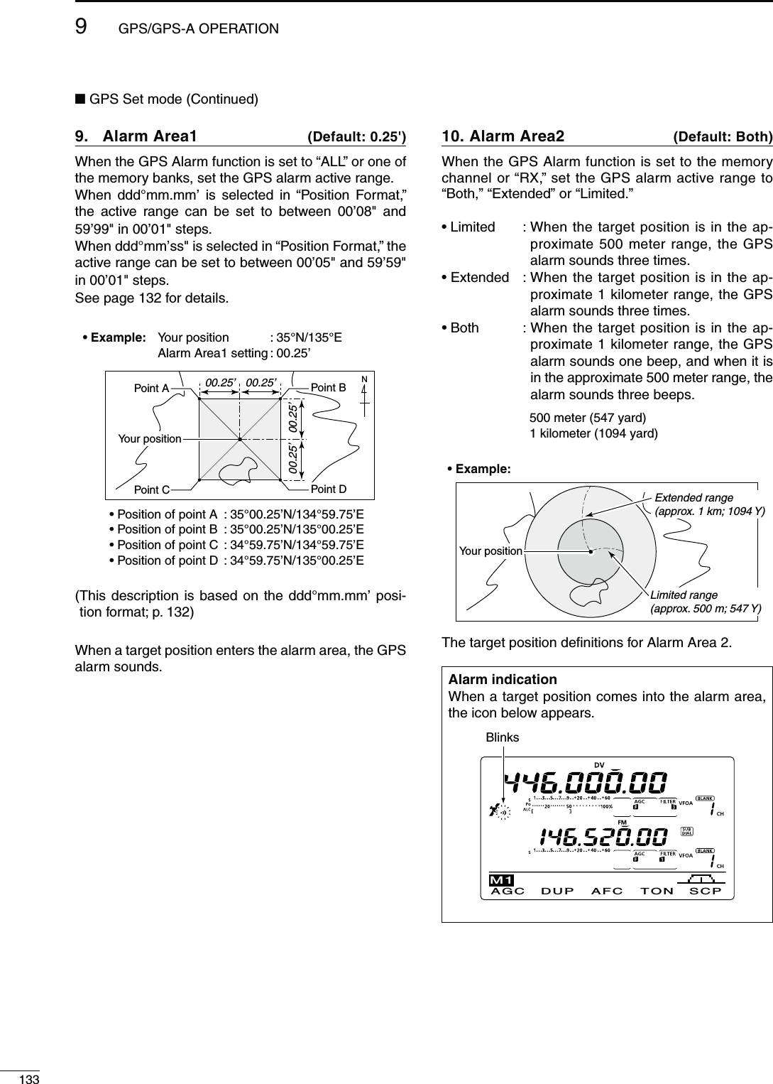
![1349GPS/GPS-A OPERATION9GPS Auto TX 11. $EFAULT/&&Select the desired interval from OFF, 5, 10, 30 sec-onds, 1, 3, 5, 10 or 30 minutes for automatic position data transmission.The current position data, received from a GPS re-ceiver, is transmitted at the selected interval when “GPS” or “GPS-A” is selected as the “GPS TX Mode” option as described below.The GPS message is transmitted as well as the posi-tion data, if it is programmed.Even if this setting is set to OFF, you can manually transmit the position data by pushing [TRANSMIT] or [PTT] (microphone).NOTE:s7HENFOUR'03SENTENCES ARE SELECTED AT THE same time, “5sec” cannot be selected.s7HENh-ANUALvISSELECTEDINh-Y0OSITIONvTHEcurrent position data will not be automatically transmitted.GPS TX Mode 12. $EFAULT$ISABLESelect the GPS or GPS-A operating mode to transmit the position data from a GPS receiver, or turn OFF the function.NOTE: When “GPS” or “GPS-A” is selected, low-speed data communication cannot be used.'033ENTENCE2-#13. *1 $EFAULT/&&Turn the GPS sentence formatter “RMC” ON or OFF.'033ENTENCE''!14. *1 $EFAULT/.Turn the GPS sentence formatter “GGA” ON or OFF.'033ENTENCE',,15. *1 $EFAULT/&&Turn the GPS sentence formatter “GLL” ON or OFF.'033ENTENCE'3!16. *1 $EFAULT/&&Turn the GPS sentence formatter “GSA” ON or OFF.'033ENTENCE64'17. *1 $EFAULT/&&Turn the GPS sentence formatter “VTG” ON or OFF.'033ENTENCE'3618. *1 $EFAULT/&&Turn the GPS sentence formatter “GSV” ON or OFF../4%FOR'03SENTENCESs5PTOFOUR'03SENTENCESAREUSABLEATTHESAMEtime.s3EEPAGEFOR'03SENTENCESETTINGDETAILS5NPROTO!DDRESS19. *2 $EFAULT!0)$34!21Enter an unproto address of up to 56 characters. The manually programmed data can be memorized.s5NPROTOADDRESSPROGRAMMINGq Push [EDT](F-4) to enter the unproto address edit mode.w Push [F-1] one or more times to select the desired character type.#HARACTERTYPE 3ELECTABLECHARACTERSABC A to Zabc a to zetc <" ’ ` ^ + – 1b( ) [ ] { } ¦ _ ¯ @e Rotate [MAIN DIAL] to select the first character or symbol to input.s7HENENTERINGNUMBERORADECIMALPOINTPUSHTHEAP-propriate keypad key. s0USH;$%,=&TODELETETHESELECTEDCHARACTERSYM-bol or number. s0USH;30#=&TOINPUTASPACE s7HENALL CHARACTERSHAVEBEENprogrammed, an error beep sounds. If you want to reprogram, push [Ω](F-2) or [≈](F-3) to select a character, then push [DEL](F-4) to delete it.r Push [Ω](F-2) to move the cursor backward, or push [≈](F-3) to move the cursor forward.t Repeat steps w through r to program an unproto address of up to 56 characters.y Push [MENU] to save the unproto address, and re-turn to the “SET” screen.*1 Appears when “GPS” is selected in “GPS TX Mode.”*2 Appears when “GPS-A” is selected in “GPS TX Mode.”](https://usermanual.wiki/ICOM-orporated/318300.User-Manual-2/User-Guide-1415350-Page-42.png)
![1359GPS/GPS-A OPERATIONN GPS Set mode (Continued)$ATA%XTENSION20. * $EFAULT/&&Set the data extension capability to “Course/Speed” or OFF.When you select “Course/Speed,” the transceiver’s course and speed information is transmitted along with the position data.NOTE: When “Course/Speed” is selected, “Com-ment (Extension)” appears instead of “Comment,” and number of characters is limited to 36.4IME3TAMP21. * $EFAULT/&&Select either the DHM or HMS format to transmit the current UTC (Universal Time Coordinated) time as a time stamp, or turn OFF the function.s/&& $OESNOTTRANSMITTHETIMEINFORMATIONs$(-4RANSMITSTHETIMESTAMPINTHE$AY(OURand Minute format.s(-34RANSMITSTHETIMESTAMPINTHE(OUR-INUTEand Second format.'03!3YMBOL22. * $EFAULT(OUSE14(6(&Select the desired GPS-A symbol which represents your means of transportation. Selectable symbols:!MBULANCE"US&IRE4RUCK"ICYCLE9ACHT(ELICOPTERSmall Aircraft, Ship, Car, Motorcycle, Balloon, Jeep, RV, Truck, Van, House QTH (VHF) and OtherIf there is no symbol you want to use, you can make a desired symbol code, as described below.s3YMBOLPROGRAMMINGq Rotate [MAIN DIAL] to select “Other.” s;%$4=&ANDTHECURRENTSYMBOLCODEAPPEARw Push [EDT](F-4) to enter the programming mode. s!CURSORBLINKSON“ ⁄ ”.e Rotate [MAIN DIAL] to select the first digit character to input. 5SABLECHARACTERSb<TO!TO:r Push [≈](F-3) to select the second digit. s!CURSORBLINKSON“–”.t Push [F-1] one or more times to select the desired character type.#HARACTERTYPE 3ELECTABLECHARACTERSABC A to Zabc a to zetc <" ’ ` ^ + – 1b[ ] { } ¦ _ ¯ @ (space)y Rotate [MAIN DIAL] to select the second digit char-acter to input. When inputting numbers or a decimal point, push the appropriate keypad key.u Push [MENU] to save the symbol code, and return to the “SET” screen.When “Other” is selected, check the symbol codes of APRS®, and set them correctly.SSID23. * $EFAULTTo assist in identifying a station’s type, the displayed APRS® based SSID is added after the GPS-A data call sign.s $OESNOTUSEANY33)$(OWEVERIFYOUuse a capital letter, it will be used as an SSID. %XAMPLE *!95!¨*!95! *!95!!¨*!95!!s .O33)$)FYOUUSEACAPITALLETTERITWILLbe deleted. %XAMPLE *!95!¨*!95! *!95!!¨*!95!sTO !DDSAN33)$OFTOTOYOURCALLsign. If you use a capital letter, it will be replaced with the SSID. %XAMPLEhvISENTERED *!95!¨*!95! *!95!!¨*!95!NOTE: If you have multiple transceivers, your call signs are distinguished by a single capital letter in the D-STAR* system. When you use an SSID, the capital letter will be replaced by the SSID, depend-ing on the setting.* Appears when “GPS-A” is selected in “GPS TX Mode.”](https://usermanual.wiki/ICOM-orporated/318300.User-Manual-2/User-Guide-1415350-Page-43.png)
 to enter the programming mode. s!CURSORAPPEARSANDBLINKSw Push [F-1] one or more times to select the desired character type.#HARACTERTYPE 3ELECTABLECHARACTERSABC A to Zabc a to zetc <" ’ ` ^ + – 1b( ) [ ] { } ¦ _ ¯ @e Rotate [MAIN DIAL] to select the first character or symbol to enter. When inputting numbers or a decimal point, push the appropriate keypad key. s0USH;$%,=&TODELETETHESELECTEDCHARACTERSYM-bol or number. s0USH;30#=&TOINPUTASPACE s7HENALLORCHARACTERSHAVEBEENprogrammed, an error beep sounds. If you want to reprogram, push [Ω](F-2) or [≈](F-3) to select a character, then push [DEL](F-4) to delete it.r Push [Ω](F-2) to move the cursor backward, or push [≈](F-3) to move the cursor forward.t Repeat steps w through r to program a comment of up to 43 characters*. * 36 characters can only be programmed when “Course/Speed” is selected in “Data Extension.”y Push [MENU] to save the comment, and return to the “SET” screen.](https://usermanual.wiki/ICOM-orporated/318300.User-Manual-2/User-Guide-1415350-Page-44.png)
![1379GPS/GPS-A OPERATIONN'03!OPERATIOND'03!FUNCTIONSet the following to activate the GPS-A function.q Push [DVsDR] to select the DV mode.w Enter the GPS Set mode.e Set the desired position data transmitting interval in “GPS Auto TX.” (p. 134)r Select “GPS-A” in “GPS TX Mode.” (p. 134)t Set the GPS-A mode operation’s items. (pp. 134–136)D'03!CODEDETAILSIn GPS-A operation, the following codes are transmit-ted to the PC connected to the IC-9100.GPS-A code is based on APRS® code.(APRS® : Automatic Position Reporting System)JA3YU!!0)$34AR∗H.%)AMHERE#ANYOUSEEME9our own call signUnproto addressTime stampTime stamp H H.M.S (Hour/Minute/Second)Z D.H.M (Day/Hour/Minute)LatitudeLongitudeData extensionCommentGPS-A symbol (Car)s'03!CODEDETAILS7HENCONNECTINGTHE0#WITHTHE53"PORTConnect a USB cable* between the transceiver’s USB port on the rear panel and the PC. (p. 26)When “DV dat” is selected as the “USB2/DATA1 Func” (63) item option, the GPS-A data can be send from the USB port. (p. 167)* Purchase separately7HENCONNECTINGTHE0#WITHTHE;$!4!=JACKConnect the optional OPC-1529R between the trans-ceiver’s [DATA1] jack on the rear panel and the PC. (p. 26)When “DV dat” is selected as the “USB2/DATA1 Func” (64) item option, the GPS-A data can be send from the [DATA1] port. (p. 168)](https://usermanual.wiki/ICOM-orporated/318300.User-Manual-2/User-Guide-1415350-Page-45.png)
![10138MEMORY OPERATION10N'ENERALDESCRIPTIONThe transceiver has 106 Memory channels in each fre-quency band. (99 regular, 6 scan edges and 1 call)The Memory mode is very useful to quickly change to often-used frequencies.While in the memory mode, all 106 Memory channels are tunable, which means the programmed frequency can be tuned temporarily with [MAIN DIAL].NOTE:Memory data can be erased by static electricity, elec-tric transients, etc. In addition, they can be erased by malfunction and during repairs. Therefore, we recom-mend that memory data be backed up or be saved to a PC using the optional CS-9100 CLONING SOFT-WARE.-EMORY#HANNELS $ESCRIPTIONS1–99 Regular Memory channels with Split frequency capability.*1A/1b–3A/3b Program Scan Edge Memory channels with only Simplex capability.Stores the scan edge frequencies for programmed scans.C Call channel with Split frequency capability*. Instantly recalls a specified frequency.*Usable only on HF/50 MHz frequency bands.D-EMORYCHANNELCONTENTSThe following information can be programmed into Memory channels:s/PERATINGFREQUENCYPs/PERATINGMODEPs)&lLTERNUMBERPs3PLITDATAP ( Usable only on the regular Memory channels and Call channel on HF/50 MHz frequency bands.)s-EMORYNAMEPs$UPLEXDIRECTION$50ORn$50ANDFREQUENCYOFF-set (pp. 65, 163)s3UBAUDIBLETONEENCODERPTONESQUELCHORDTCS squelch ON/OFF (pp. 62, 63)s3UBAUDIBLETONEFREQUENCYPTONESQUELCHFRE-quency or DTCS code with polarity (pp. 62, 63)s523TATIONCALLSIGNP s22CALLSIGNPs#ALLSIGNSQUELCHOR$IGITALCODESQUELCH/./&&(p. 114) s$IGITALCODEPThe optional UT-121 is required for DV mode operation.](https://usermanual.wiki/ICOM-orporated/318300.User-Manual-2/User-Guide-1415350-Page-46.png)
![13910 -%-/29/0%2!4)/.N-EMORYCHANNELSELECTIONWhen the SUB Band setting is turned ON, you can se-lect a Memory channel in the SUB Band as well as in the MAIN Band. (p. 33)sh ” appears when the SUB Band setting is ON.D3ELECTIONINTHE6&/MODEq Push [VFO/MEMO] to select the VFO mode.w Rotate [M-CH] to select a Memory channel num-ber. s2OTATECLOCKWISETOSELECTAHIGHER-EMORYCHANNELNUMBERROTATECOUNTERCLOCKWISETOSELECTALOWER-EM-ory channel number. s!LL-EMORYCHANNELSINCLUDINGBLANKCHANNELSCANBEselected.sh” appears when no information has been pro-grammed into the Memory channel. (Blank channel)e Push [VFO/MEMO] to select the Memory mode. sh-%-/vANDCONTENTSOFTHE-EMORYCHANNELAPPEARD3ELECTIONINTHE-EMORYMODEq Push [VFO/MEMO] to select the Memory mode.w Rotate [M-CH] to select a Memory channel. s2OTATECLOCKWISETOSELECTAHIGHER-EMORYCHANNELNUMBERROTATECOUNTERCLOCKWISETOSELECTALOWER-EM-ory channel number. s!LL-EMORYCHANNELSINCLUDINGBLANKCHANNELSCANBEselected.sh” appears when no information has been pro-grammed into the Memory channel. (Blank channel) s-EMORYCHANNELSCANALSOBESELECTEDUSINGTHEMICRO-phone [UP]/[DN] keys. In such case, the blank channels are skipped.[VFO/MEMO] [M-CH]While in the VFO modeAppears if the selected Memory channel has no information.While in the Memory modeN#ALLCHANNELSELECTIONEach frequency band has its own Call channel. Fac-tory default frequency and operating modes are pro-grammed into the Call channel. Change these to suit your operating needs. (see page 141)q0USH;#!,,s'03=TOSELECTTHE#ALLCHANNEL s!CAPITALh#vAPPEARSw 0USH;#!,,s'03=AGAINTORETURNTOTHEPREVIOUSscreen display.Appears](https://usermanual.wiki/ICOM-orporated/318300.User-Manual-2/User-Guide-1415350-Page-47.png)
![14010-%-/29/0%2!4)/.10Memory channels can be programmed in either the VFO mode or the Memory mode.D0ROGRAMMINGINTHE6&/MODEq Push [VFO/MEMO] to select the VFO mode.w Set the desired settings into both VFO A and VFO B.± Select the band using [BAND](MAIN/SUB).± Set the frequency with [MAIN DIAL] or the key-pad. (p. 37)± Set the operating mode with the mode switch. (p. 43)± Set other data (e.g. frequency offset, duplex di-rection, tone squelch, split frequency operation, etc.), if desired. (p. 138)e Rotate [M-CH] to select the Memory channel num-ber to be programmed.sh” appears if the selected Memory channel is a blank channel.r Hold down [MW] for 1 second to program the con-tents into the Memory channel.s4HREEBEEPSSOUNDWHENTHEmemory programming is complete.D0ROGRAMMINGINTHE-EMORYMODEq Push [VFO/MEMO] to select the Memory mode.w Rotate [M-CH] to select the Memory channel to be programmed.s4HECONTENTSOFTHE-EMORYCHANNELAPPEARINTHEDIS-play.sh” appears if the selected Memory channel is a blank channel.e Set the desired settings into the Memory channel.± Set the frequency with [MAIN DIAL] or the key-pad. (p. 37)s7HENABLANKCHANNELISSELECTEDYOUMUSTSETTHEdesired frequency using the keypad.± Set the operating mode with the mode switch.± Set other data (e.g. frequency offset, duplex di-rection, tone squelch, etc.), if desired.r Hold down [MW] for 1 second to program the con-tents into the Memory channel.s4HREEBEEPSSOUNDWHENTHEMEMORYPROGRAMMINGIScomplete.NOTE: If you perform the above operations in a pre-programmed channel, the previous channel data will be overwritten.N-EMORYCHANNELPROGRAMMING[MW] [M-CH][EXAMPLE]:Programming 7.088 MHz/LSB into the Mem-ory channel 12 while in the VFO mode.[EXAMPLE]:Programming 21.280 MHz/USB into Memory channel 18 while in the Memory mode.s$URINGSETTINGTHECONTENTS[MAIN DIAL]Keypad[BAND](MAIN/SUB)Mode selection](https://usermanual.wiki/ICOM-orporated/318300.User-Manual-2/User-Guide-1415350-Page-48.png)
![14110 -%-/29/0%2!4)/.N#ALLCHANNELPROGRAMMINGThe Call channel is programmed in the same way as the regular Memory channels are. It is convenient to program a most-often-used frequency into the Call channel for quick recall. As with Memory channels, the Call channel can also hold split frequencies, and other parameters. See page 138 for details.q Rotate [M-CH] to select the Call channel.sA capital “C” appears.w Select the desired frequency and operating mode to program into the Call channel.e Hold down [MW] for 1 second to program the dis-played frequency and operating mode into the Call channel.s4HREEBEEPSSOUNDWHENMEMORYPROGRAMMINGISCOM-plete.IMPORTANT!7HENTHE#ALLCHANNELISSELECTEDWITH;#!,,s'03=you cannot change the memory contents. However, when the Call channel is selected using [M-CH] in the VFO or Memory mode, the memory contents can be changed.[MW] [M-CH]AppearsAppears[VFO/MEMO] [M-CH][M-CLR]Hold downThe operating band appears.N-EMORYCLEARINGAny no-longer-used regular Memory channels can be cleared, and then become blank channels.q Push [VFO/MEMO] to select the Memory mode.w Rotate [M-CH] to select the regular Memory chan-nel to be cleared.e Hold down [M-CLR] for 1 second to clear the con-tents.s4HEPROGRAMMEDCONTENTSDISAPPEARsh” appears.s4HREEBEEPSSOUNDWHENTHEMEMORYCLEARINGISCOM-plete.r To clear other Memory channels, repeat steps w and e.!BOUTTHEBLANKCHANNELDISPLAYWhen a blank channel is selected, or after clearing the Memory channel contents, the “ ” icon ap-pears, and then after 2 seconds, the operating band appears.](https://usermanual.wiki/ICOM-orporated/318300.User-Manual-2/User-Guide-1415350-Page-49.png)
![14210-%-/29/0%2!4)/.10The Memory channel contents (frequency, operating mode, etc.) can be copied to the VFO.The copy can be performed in either the VFO mode or the Memory mode.D#OPYINGINTHE6&/MODEThis is useful for copying programmed contents toa displayed VFO.q Push [VFO/MEMO] to select the VFO mode.w Rotate [M-CH] to select the Memory channel num-ber to be copied.sh” appears if the selected Memory channel is a blank channel. In this case nothing can be copied.e Hold down [VFO/MEMO] for 1 second to copy the Memory channel contents into the VFO.s4HREEBEEPSSOUNDWHENTHECOPYISCOMPLETED#OPYINGINTHE-EMORYMODEThis is useful for copying the Memory channel con-tents while operating in the Memory mode.When you have changed the displayed frequency, operating mode, etc. in the selected Memory chan-nel:s$ISPLAYEDdata is copied.s0ROGRAMMEDcontents in the Memory channel are not copied, but remain only in the Memory chan-nel.q Push [VFO/MEMO] to select the Memory mode.w Rotate [M-CH] to select the Memory channel to be copied.sh” appears if the selected Memory channel is a blank channel. In this case nothing can be copied. s3ETTHEFREQUENCYOROPERATINGMODEIFREQUIREDe Hold down [VFO/MEMO] for 1 second to copy the Memory channel contents into the VFO.s4HREEBEEPSSOUNDWHENTHETRANSFERISCOMPLETEr Push [VFO/MEMO] to select the VFO mode.[VFO/MEMO] [M-CH]Hold downPushWhile in the Memory modeThe Memory channel contents are transferredHold downWhile in the VFO modeThe Memory channel contents are transferredN-EMORYCONTENTSCOPYING](https://usermanual.wiki/ICOM-orporated/318300.User-Manual-2/User-Guide-1415350-Page-50.png)
![14310 -%-/29/0%2!4)/.N-EMORYNAMEPROGRAMMINGAll Memory channels, including scan edges and Call channel, can be tagged with alphanumeric names of up to 9 characters each.[EXAMPLE]: Programming a memory name into Memory channel 99.q Push [VFO/MEMO] to select the Memory mode.w Rotate [M-CH] to select Memory channel 99.e Push [MENU] one or more times to display the “M2” screen (Menu 2).r Push [MEM](F-2) to display the “MEM” screen (Memory Menu).t Push [EDT](F-1) to display the “EDT” screen (Mem-ory name Edit). s!CURSORAPPEARSANDBLINKS s)FTHECHANNELYOUSELECTISABLANKCHANNELANERRORbeep sounds after pushing [EDT](F1).y Push [F-1] one or more times to select the desired character type. s3EEh#HARACTERTABLELISTvASSHOWNBELOWu Rotate [MAIN DIAL] to select the first character or symbol to input. When inputting numbers and a decimal point, push the appropriate keypad key. s0USH;$%,=&TODELETETHESELECTEDCHARACTERSYM-bol or number. s0USH;30#=&TOINPUTASPACE s7HENALLCHARACTERSHAVEBEENprogrammed, an error beep sounds. If you want to reprogram, push [Ω](F-2) or [≈](F-3) to select a character, then push [DEL](F-4) to delete it.i Push [Ω](F-2) to move the cursor backwards, or push [≈](F-3) to move the cursor forwards.o Repeat steps y to i to program a memory name of up to 9 characters.!0 Push [MENU] to save the name, and return to the “MEM” screen (Memory Menu).!1 Push [MENU] to return to the “M2” screen (Menu 2).#HARACTERTABLELIST#HARACTERTYPE 3ELECTABLECHARACTERSABC A to Zabc a to zetc <" ’ ` ^ + – 1b;=[]¦ _ ¯ @[VFO/MEMO] [MEM] [EDT] [M-CH][MENU]SCAN ME M S WR TCON VS CM2EDT ( ) SELMEM14.19500 USBABCDEL SPCEDT[][][F-1] [DEL][SPC] [MAIN DIAL]Keypads7HENPROGRAMINGAMEMORYNAMEabcDEL SPCEDTDX spotCharacter type CursorInput a spaceDelete a characterMove cursor forwardsMove cursor backwardsSelect character type[EXAMPLE]: Programming “DX spot” into Memory channel 99.PushPush](https://usermanual.wiki/ICOM-orporated/318300.User-Manual-2/User-Guide-1415350-Page-51.png)
![14410-%-/29/0%2!4)/.109OUCANCALLUPAMEMOPADBYPUSHING;-02=ONEORmore times while in either the VFO or Memory mode.s4HEMEMOPADDATAISCALLEDUPSTARTINGFROMTHEMOSTrecently written.When you call up a memo pad, the previously dis-played data is automatically stored in a temporary pad. The temporary pad can be recalled by pushing [MP-R] one or more times.s9OUMAYTHINKTHEREAREMEMOPADSBECAUSEDIFFERENTfrequencies (5 are in memo pads and 1 is in the temporary pad) are called up by [MP-R].If you change the data called up from a memo pad, the stored temporary pad data is replaced with the changed data.N-EMOPADFUNCTIONThe transceiver has a Memo pad function to store the displayed data for easy writing and recalling. The memo pads are separate from the Memory channels.The default number of memo pads is 5. However, you can increase the number to 10 in the “Memopad Num-bers” item of the Set mode, if desired. (p. 164)Memo pads are convenient when you want to memo-rize the displayed data temporarily, such as when you find a DX station in a pile-up, or when a desired station is busy for a long time and you want to temporarily search for other stations.Use the transceiver’s memo pads instead of relying on hastily scribbled notes that are easily misplaced.D7RITINGTHEDISPLAYEDDATAINTOMEMOPADS9OUCANSTORETHEDISPLAYEDDATABYPUSHING;-07=When you store the 6th data into memo pads, the old-est stored entry is automatically erased, to make room for the new data.AGC DUP COMP TBW SCPM1In this example, 21.347 MHz (USB) will be erased when 21.280 MHz (LSB) is written.Memo padsErased[MP-W] NewestOldestAGC DUP COMP TBW SCPM1[MP-R] NewestOldest[MP-R]NOTE: Each memo pad must have its own unique SETOFDATAMEMOPADSHAVINGIDENTICALDATACANNOTbe written.D #ALLINGUPTHEMEMOPADSMemo padsPushPushPush](https://usermanual.wiki/ICOM-orporated/318300.User-Manual-2/User-Guide-1415350-Page-52.png)
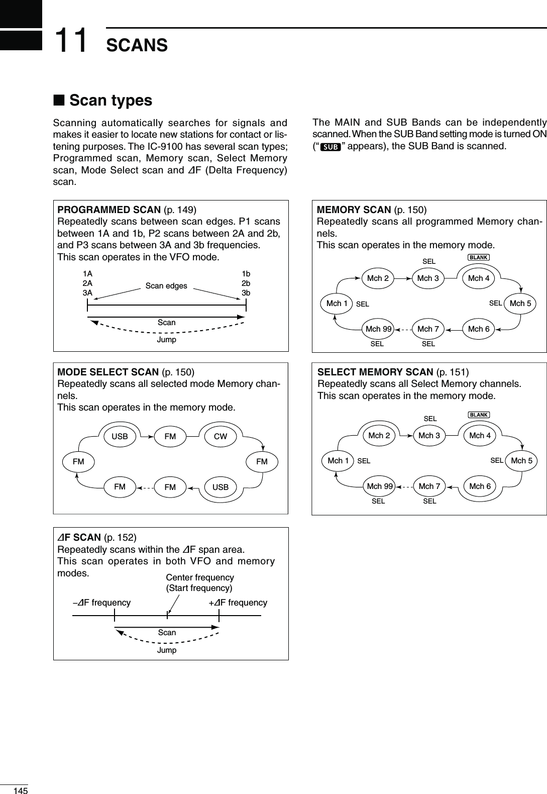
![14611SCANS11N0REPARATION&ORA0ROGRAMMEDSCANProgram scan edge frequencies into Program Scan Edge channels “1A–3A” and “1b–3b.” (p. 148)&ORA-EMORYSCANProgram two or more Memory channels. (Program Scan Edge channels will not be scanned.) (p. 140)&ORA-ODE3ELECTSCANProgram two or more Memory channels, all with the same operating mode. (p. 43)&ORA3ELECT-EMORYSCANProgram two or more Memory channels as Select Memory channels. (p. 151)&ORA∂&SCANSet the ∂F span (∂F scan range) in the “SCAN” screen. (p. 152)s3CAN2ESUMEFUNCTION9OUCANSELECTTHESCANTORESUMEORCANCELWHENDE-tecting a signal in the Scan Set mode. The Scan Re-sume function must be set before operating a scan. (p. 147)s3CANSPEEDThe scan speed can be set to high or low in the Scan Set mode. (p. 147)s;-!).$)!,=FUNCTIONHow the [MAIN DIAL] functions during a scan, can be set in the Scan Set mode. (p. 147)s3QUELCHSTATUSM4HESCANSTARTSWITHTHESQUELCHOPEN&ORAPROGRAMMEDSCANWhen the tuning step is 1 kHz or less:The scan continues until it is stopped manually— it does not pause*, even if signals are detected.* The scan is paused when the squelch is closed and then opened. The scan resumes, or is cancelled, depending on the Scan Resume setting.When the tuning step is 5 kHz or more:If Scan Resume is ON, the scan pauses on each step when a signal is detected, then resumes.If the Scan Resume is OFF, the scan does not start.&ORMEMORYSCANIf Scan Resume is ON, the scan pauses on each channel when a signal is detected, then resumes.If Scan Resume is OFF, the scan does not start.M4HESCANSTARTSWITHSQUELCHCLOSEDThe scan pauses when signals are detected. The scan resumes, or is cancelled, depending on the Scan Re-sume setting.-ODE33"!-&-This function is useful when you do not want unmodu-lated signals pausing or cancelling a scan. When the Voice Squelch Control (VSC) function is ON, the re-ceiver checks received signals for voice components.The scan pauses, or is cancelled, if a received signal includes voice components, and the tone of the voice components changes within 1 second. See “Squelch status” as described above.The scan resumes if the received signal includes no voice components, or the tone of the voice compo-nents does not change within 1 second.q Push [SSB] or [AM/FM] once or twice to select the operating mode.w Push [MENU] to display the “M2” screen (Menu 2).e Push [VSC](F-5) to turn the VSC function ON or OFF.sh ” appears when the VSC function is ON. s0USH;-%.5=TORETURNTOTHEPREVIOUSDISPLAYs4HE63#FUNCTIONISAVAILABLEFORPHONEMODES(SSB, AM and FM).s4HE63#FUNCTIONRESUMESTHESCANONUNMODU-lated signals, regardless of whether the Scan Re-sume function is set to ON or OFF.N6OICE3QUELCH#ONTROLFUNCTIONSCAN ME M S WR TCON VS CM2Appears](https://usermanual.wiki/ICOM-orporated/318300.User-Manual-2/User-Guide-1415350-Page-54.png)
![14711 SCANSN3CANSETMODEThe scan speed, Scan Resume function and [MAIN DIAL] scan function can be set in the Scan Set mode.q Push [MENU] one or more times to display the “M2” screen (Menu 2).w Push [SCAN](F-1) to display the “SCAN” screen.e Push [SET](F-5) to enter the Scan Set mode.r Push [Y](F-1) or [Z](F-2) to select the desired item.t Rotate [MAIN DIAL] to select the desired option.s(OLDDOWN;&=FORSECONDTORESETTOTHEDEFAULTvalue.y Push [MENU] to save, and return to the “SCAN” screen.u Push [MENU] again to return to the “M2” screen (Menu 2).[SET] [SCAN]/[] [MENU] [F-3] [MAIN DIAL][]SCAN ME M S WR TCON VS CM2PRO FSPAN S E TFINSCANPROG:P1F: 10kÚSCAN SpeedÙ1 HIGHSETÚSCAN ResumeÙ2ONSETÚMAIN DIAL (SCAN)Ù3 Up/DownSET3#!.3PEED1. $EFAULT()'(Select the desired scan speed between high and low.s()'( 4HESCANISFASTERs,/7 : The scan is slower.SCAN Resume 2. $EFAULT/.Set the Scan Resume function ON or OFF.s/. 7HENASIGNALISDETECTEDTHESCANPAUSESFOR10 seconds, then resumes. When a signal dis-appears, the scan resumes 2 seconds later.s/&&7HENASIGNALISDETECTEDTHESCANISCAN-celled.-!).$)!,3#!.3. $EFAULT5P$OWNSelect how the [MAIN DIAL] functions, during a scan.s/&& 2OTATING;-!).$)!,=CANCELSTHESCANs5P$OWN 2OTATING;-!).$)!,=CHANGESTHESCAN-ning direction.PushPushPushPush](https://usermanual.wiki/ICOM-orporated/318300.User-Manual-2/User-Guide-1415350-Page-55.png)
![14811SCANS11N3CANEDGESPROGRAMMINGMemory channels 1A–3A and 1b–3b are the Program Scan Edge channels. They are used to program the upper and lower frequency edges for programmed scans. (p. 149)Each frequency band has its own Scan Edge chan-nels. Factory default frequency and operating modes are programmed into the Scan Edge channels.If both upper and lower band edges are programmed with the same frequency, a programmed scan can-not start.EXAMPLE: Programming 14.00000 MHz into 1A and 14.35000 MHz into 1b.q Push [VFO/MEMO] to select the VFO mode.w Rotate [M-CH] to select scan edge 1A.e Set 14.00000 MHz as the lower frequency.r Hold down [MW] for 1 second to program 14.00000 MHz into scan edge 1A.s4HREEBEEPS SOUND WHEN THEPROGRAMMING ISCOM-plete.t Rotate [M-CH] to select scan edge 1b.y Set 14.35000 MHz as the upper frequency.u Hold down [MW] for 1 second to program 14.35000 MHz into scan edge 1b.s4HREEBEEPS SOUND WHEN THEPROGRAMMING ISCOM-plete.i If 1A/1b is selected as the scanning range when a programmed scan is started, it will search for sig-nals between 14.00000 MHz and 14.35000 MHz. (p. 149)[VFO/MEMO] [MW] [M-CH]Programming 14.00000 MHz into 1AProgramming 14.35000 MHz into 1b](https://usermanual.wiki/ICOM-orporated/318300.User-Manual-2/User-Guide-1415350-Page-56.png)
![14911 SCANSA programmed scan searches for signals between Program Scan Edge channels “1A–3A” and “1b–3b.”Before starting the programmed scan, scan edges must be programmed into these channels.See the previous page for scan edge programming.If the same frequencies are programmed into the Program Scan Edge channels, the programmed scan will not start.q Push [VFO/MEMO] to select the VFO mode.w Push the mode switch to select the desired operat-ing mode.s4HEOPERATINGMODECANALSOBECHANGEDWHILESCAN-ning.e Push [TS] one or more times to select a tuning step. (p. 38) s4HETUNINGSTEPCANALSOBECHANGEDWHILESCANNINGr Push [MENU] one or more times to display the “M2” screen (Menu 2).t Push [SCAN](F-1) to display the “SCAN” screen.y Set [RF/SQL] open or closed.s4HESCANPERFORMANCEDIFFERSDEPENDINGONTHESQUELCHsetting when the scan was started. See page 146 for details.s)FTHE;2&31,=CONTROLFUNCTIONISSETTOh!54/vTHESQUELCHIS ALWAYSOPENINTHE 33"#7 AND 2449modes. (pp. 44, 162)u Hold down [PRO](F-1) for 1 second to select the desired scan range between “P1,” “P2” and “P3.”s4HESCANSEARCHESBETWEENPROGRAMMEDSCANCHAN-nels 1A–1b (P1), 2A–2b (P2) or 3A–3b (P3).i Push [PRO](F-1) to start the programmed scan.s4HE-(ZANDK(ZDECIMALPOINTSANDTHESELECTEDSCANrange display blink while scanning. s)F“Up/Down” is selected as the “MAIN DIAL (SCAN)” option in the Scan Set mode, rotating [MAIN DIAL] changes the scanning direction. (p. 147)o When the scan detects a signal, the scan stops, pauses or ignores it, depending on the Scan Re-sume function, the VSC function or the squelch sta-tus.!0 Push [PRO](F-1) to cancel the scan.N0ROGRAMMEDSCAN&INEPROGRAMMEDSCAN6&/MODED!BOUTTHE&INEPROGRAMMEDSCANWhen a signal is received during Fine programmed scan, the scanning tuning step is temporarily set to 10 Hz and the scan speed decreases.q Start the programmed scan. s&OLLOWSTEPSq through i as described above.w While scanning, push [FIN](F-3) to switch the scan function between a programmed scan and a Fine programmed scan.e Push [PRO](F-1) to cancel the scan.[SCAN]/[PRO] [VFO/MEMO] [TS] [MENU][RF/SQL] Mode switchesPRO ∂FSPAN S E TFINSCANPROG SCAN:P2SCAN ME M S WR TCON VS CM2PRO FSPAN S E TFINSCANPROG:P1F: 10kPRO FSPAN S E TFINSCANPROG:P2F: 10kHold downWhile Programmed scanningPRO ∂FSPAN S E TFINSCANPROG SCAN:P2PRO ∂FSPAN S E TFINSCANF−PROG SCAN:P2While Fine programmed scanningPushPushPush](https://usermanual.wiki/ICOM-orporated/318300.User-Manual-2/User-Guide-1415350-Page-57.png)
![15011SCANS11D-EMORYSCANA Memory scan searches for signals through Memory channels 1 to 99.Blank (unprogrammed) Memory channels are skipped.NOTE: For a Memory scan to start, two or more Memory channels must be programmed. (p. 140)q Push [VFO/MEMO] to select the memory mode.w Push [MENU] to display the “M2” screen (Menu 2).e Push [SCAN](F-1) to display the “SCAN” screen.r Set [RF/SQL] open or closed.s4HESCANPERFORMANCEDIFFERSDEPENDINGONTHESQUELCHsetting when the scan was started. See page 146 for details.s)FTHE;2&31,=CONTROLFUNCTIONISSETTOh!54/vTHESQUELCHIS ALWAYSOPENINTHE 33"#7 AND 2449modes. (pp. 44, 162)t Push [MEM](F-1) to start the Memory scan.s4HE-(ZANDK(ZDECIMALPOINTSANDh-%-/3#!.vblink while scanning. s)F“Up/Down” is selected as the “MAIN DIAL (SCAN)” option in the Scan Set mode, rotating [MAIN DIAL] changes the scanning direction. (p. 147)y Push [MEM](F-1) to cancel the scan.N-EMORYSCAN-EMORYMODE[SCAN]/[MEM] [VFO/MEMO] [MENU][RF/SQL]SCAN ME M S WR TCON VS CM2MEM FSPAN S E TSELSCANF: 10kMEM ∂FSPAN S E TSELSCANMEMO SCANWhile Memory scanningD-ODE3ELECTSCANRepeatedly scans all Memory channels with the same operating mode as the displayed mode.NOTE: For a Mode Select scan to start, two or more Memory channels must be programmed, and their operating mode must be the same as the displayed mode.q Follow steps q through r as described above.w Hold down [MEM](F-1) for 1 second to turn ON the Mode Select scan. sh-/$%3vAPPEARSe Push the mode switch to select the desired operat-ing mode to be scanned.r Push [MEM](F-1) to start the Mode Select scan.s4HE-(Z AND K(ZDECIMAL POINTSANDh-/$%3%,SCAN” blink while scanning. s)F“Up/Down” is selected as the “MAIN DIAL (SCAN)” option in the Scan Set mode, rotating [MAIN DIAL] changes the scanning direction. (p. 147) s-EMORYSCANAND-ODE3ELECTSCANCANBESWITCHEDby holding down [MEM](F-1) for 1 second.t Push [MEM](F-1) to cancel the scan.While Mode Select scanningPushPushMEM ∂FSPAN S E TSELSCANMODE−SEL SCAN[SCAN]/[MEM] [VFO/MEMO] [MENU][RF/SQL] Mode switches](https://usermanual.wiki/ICOM-orporated/318300.User-Manual-2/User-Guide-1415350-Page-58.png)
 to turn ON the Select Memory scan.s4HESCANCHANGESTOA3ELECT-EMORYSCAN sh3%,n-%-/3#!.vBLINKSWHILESCANNING s0USHING;3%,=&TOGGLESBETWEEN-EMORYSCANORMode Select scan)* and Select Memory scan. *Only when the Mode Select scan is turned ON. s)F“Up/Down” is selected as the “MAIN DIAL (SCAN)” option in the Scan Set mode, rotating [MAIN DIAL] changes the scanning direction. (p. 147)e Push [MEM](F-1) to cancel the scan.All Memory channels can be set as Select Memory channels, except for the Scan Edge and Call channels.± When the “SCAN” screen is displayed, push [SEL](F-3), or when the “MEM” screen (Memory Menu) is displayed, push [SEL](F-5) to set or cancel the displayed Memory channel as a Select Memory channel.sh3%,vAPPEARS WHENTHECHANNEL IS SET AS A3ELECTMemory channel. s!N ERROR BEEP SOUNDS WHEN THE DISPLAYED -EMORYchannel is a blank channel. s(OLDINGDOWN[SEL](F-3) or [SEL](F-5) for 1 second DISPLAYSh3%,!,,#LEARv(OLDDOWN;9%3=&TOclear all Select Memory channel settings.MEM ∂FSPAN S E TSELSCANMEMO SCANMEM ∂FSPAN S E TSELSCANSEL−MEMO SCANEDT ( ) SELMEM14.19500 USBMEM FSPAN S E TSELSCANF: 10kAppears“SCAN” screen“MEM” screen (Memory Menu)While Select Memory scanningN Memory scan (Memory mode) (Continued)D 3ETTING#ANCELLING3ELECT-EMORYCHANNELSPush[SEL](F-3)PushMEM ∂FSPAN S E TSELSCANMEMO SCANMEM ∂FSPAN S E TSELSCANMODE−SEL SCANHold down[MEM](F-1)Memory scanMode Select scanPush[SEL](F-3)](https://usermanual.wiki/ICOM-orporated/318300.User-Manual-2/User-Guide-1415350-Page-59.png)
![15211SCANS11∂F (Delta Frequency) scan searches for signals within the specified range with the displayed VFO frequency or Memory channel frequency as the center frequency. The frequency range is specified by the width of the selected span.q Push [VFO/MEMO] once or twice to select the VFO mode or memory mode.w Push [MENU] one or more times to display the “M2” screen (Menu 2).e Push [SCAN](F-1) to display the “SCAN” screen.r Set [RF/SQL] open or closed.s4HESCANPERFORMANCEDIFFERSDEPENDINGONTHESQUELCHsetting when the scan was started. See page 146 for details.s)FTHE;2&31,=CONTROLFUNCTIONISSETTOh!54/vTHESQUELCHIS ALWAYSOPENINTHE 33"#7 AND 2449modes. (pp. 44, 162)t Push [SPAN](F-4) one or more times to select the desired ∂F span width. sÒ K(Z Ò K(Z Ò K(Z Ò K(Z Ò K(Z±500 kHz and ±1 MHz are selectable.y Set the center frequency of the ∂F scan. s)NTHE6&/ MODEPUSHTHE KEYPADORROTATE;-!).DIAL] to set the center frequency. s)NTHEMEMORYMODEROTATE;-#(=TOSELECTTHEDE-sired Memory channel whose frequency will be the cen-ter frequency.u Push [∂F](F-2) to start the ∂F scan.sh∂F SCAN,” the MHz and kHz decimal points blink while scanning. s)F“Up/Down” is selected as the “MAIN DIAL (SCAN)” option in the Scan Set mode, rotating [MAIN DIAL] changes the scanning direction. (p. 147)i When the scan detects a signal, the scan stops, pauses or ignores it, depending on the Scan Re-sume function, VSC function or the squelch status.o Push [∂F](F-2) again to cancel the ∂F scan.N ∂&SCANAND&INE∂&SCAND!BOUTTHE&INE∂&SCANWhen a signal is received during Fine ∂F scan, the scanning tuning step is temporarily set to 10 Hz and the scan speed decreases.q Start ∂F scan. s&OLLOWSTEPSq through u as described above.w While scanning, push [FIN](F-3) to switch the scan function between ∂F scan and Fine ∂F scan.e Push [∂F](F-2) to cancel the scan.[SCAN] [VFO/MEMO] [M-CH] [MENU] [∂F] [SPAN] [MAIN DIAL]SCAN ME M S WR TCON VS CM2MEM FSPAN S E TSELSCANF: 10kMEM FSPAN S E TFINSCANF SCAN20kMEM FSPAN S E TSELSCANF: 20kFWhile ∂F scanningKeypadMEM FSPAN S E TFINSCANMEM FSPAN S E TFINSCANF−F SCANF SCAN20k20kWhile Fine ∂F scanningPushPushPushPush](https://usermanual.wiki/ICOM-orporated/318300.User-Manual-2/User-Guide-1415350-Page-60.png)
![12153SATELLITE OPERATIONBoth Satellite Mode B (435 MHz uplink, 145 MHz downlink) and Mode J (145 MHz uplink, 435 MHz downlink) can be operated with the IC-9100, and Mode L can be operated when the optional UX-9100 1200 MHz BAND UNIT is installed.Satellite communications is possible only when a sat-ellite is in view and its transponder is operating.N3ATELLITENOTES1. NEVER set the output power too high. Too much power will shorten the satellite’s life. Set your transmit power so that your downlink sig-nal level is lower than the beacon’s signal level.2. Confirm a satellite’s operating mode in advance through documentation (magazines, etc.) or via ap-propriate satellite tracking software. In the wrong mode, you cannot use the satellite, even if you re-ceive its beacon signal.3. Preamplifiers may be necessary to receive satel-lite signals. Optional amplifiers, AG-25, AG-35 and AG-1200* (for the UX-9100), can be used with the IC-9100. (p. 71) * AG-1200 has been discontinued, but it can be still be used.4. When you use a reverse tracking satellite in the SSB mode, use LSB for the uplink frequency and USB for the downlink frequency.s7HENUSINGANORMALTRACKINGSATELLITEIN33"MODEuse USB for both the uplink and downlink frequencies.Operating frequencies in the satellite mode can be se-lected either before or after selecting the mode. Nor-mal and reverse tracking are selectable.D4RANSFERRINGTHE6&/FREQUENCIESTOTHESATELLITE6&/q Select the downlink frequency (receive) in the MAIN band, and the uplink frequency (transmit) in the SUB band.w Hold down [SATELLITE] for 1 second to transfer the frequencies, selected in step q, to the satellite VFO.s4HESATELLITEMODEISAUTOMATICALLYSELECTEDAFTERTRANS-ferring. s“” and the last operated tracking icon (“ ” or “”) appear.s6&/OR-EMORYMODEDATAISDISPLAYEDONTHE35"band during satellite mode.435 MHz band435 MHz band145 MHz band145 MHz bandFUJI 3 (FO-29)UplinkDownlink-ODE*OPERATINGDIAGRAM ;%XAMPLE=&5*)&/-ODE*Uplink frequency : 145.9000–146.0000 MHzDownlink frequency : 435.8000–435.9000 MHzTracking direction : ReverseCW beacon frequency : 435.7950 MHz/RBITINFORMATIONOrbit information describes satellite location, reach-ing angles, etc. This information may be available in ham magazines or organization publications, such as those from ARRL, RSGB handbook, etc.Satellite tracking software is also convenient.N3ATELLITECOMMUNICATIONSOUTLINEN3ELECTINGTHESATELLITEMODE[SATELLITE]](https://usermanual.wiki/ICOM-orporated/318300.User-Manual-2/User-Guide-1415350-Page-61.png)
![15412SATELLITE OPERATION12N3ETTINGTHESATELLITE6&/q Push [SATELLITE] to enter the satellite mode.s“ ” and either “ ” or “ ” appear.w Push [VFO/MEMO] to toggle between the satellite VFO and Memory mode.s6&/OR-EMORYMODEDATAISDISPLAYEDONTHE35"band while in the satellite mode.e Push [MAIN](1.8 1) to enable downlink frequency tuning. s4HEUPLINKFREQUENCYDISAPPEARSr Select the downlink frequency and the operating mode. s0USH;-!).=AGAINAFTERTUNINGt Push [SUB](3.5 2) to enable uplink frequency tun-ing. s4HEDOWNLINKFREQUENCYDISAPPEARS s0USH;35"=AGAINAFTERTUNINGNOTE: To select the operating mode for uplink, push [SUB] to enable the SUB band setting mode.N4RACKINGSELECTIONq Push [SATELLITE] to enter the satellite mode.s“ ” and either “ ” or “ ” appears.w Push [NOR/REV](7 3) to toggle between normal and reverse tracking.D.ORMALTRACKINGBoth downlink and uplink frequencies simultaneously increase or decrease in the same steps when you ro-tate the [MAIN DIAL].D2EVERSETRACKINGThe downlink frequency follows the tuning dial rota-tion, however, the uplink frequency changes in the reverse direction to the [MAIN DIAL] rotation, in the same steps.[SATELLITE] [SUB] [VFO/MEMO] [MAIN](1.8 1)[SUB](3.5 2)[MAIN DIAL] [M-CH]Mode switchMAIN BandDownlink (Receive) frequencySUB BandUplink (Transmit) frequency[SATELLITE] [NOR/REV](7 3)[MAIN DIAL]Varies simultaneouslySatellite and tracking iconIn the DR mode, pushing [SATELLITE] cancels it, and then switches the transceiver to the satellite mode.If you want to operate in the DR mode after exiting THESATELLITEMODEYOUMUSTHOLDDOWN;$6s$2=FOR1 second.](https://usermanual.wiki/ICOM-orporated/318300.User-Manual-2/User-Guide-1415350-Page-62.png)
![15512 SATELLITE OPERATIONN3ATELLITEMEMORYThe IC-9100 has 20 satellite memory channels (CH 00 to 19) to memorize both uplink and downlink frequen-cies, operating modes and other data.D3ATELLITEMEMORYSELECTIONq Push [SATELLITE] to enter the satellite mode.w Push [VFO/MEMO] to select the satellite memory mode.sh-%-/vANDTHEMEMORYCHANNELNUMBERAREDISPLAYEDbeside the uplink frequency (SUB band) display.e Rotate [M-CH] to select a satellite mode Memory channel.D3ATELLITEMEMORYPROGRAMMINGq Push [SATELLITE] to enter the satellite mode.w Push [VFO/MEMO] to select the satellite memory mode.e Rotate [M-CH] to select the desired Memory chan-nel.r Select the desired downlink frequency in the MAIN band, and uplink frequency in the SUB band, as well as the operating mode.t Hold down [MW] for 1 second to program the con-tents into the Memory channel.s4HREEBEEPSSOUNDWHENTHEmemory programming has completed.NOTE: Tracking selection, normal or reverse, is not programmed in the satellite memory channels.Satellite memory channelSelect the desired satellite memory channelDownlink (Receive) frequencyUplink (Transmit) frequency](https://usermanual.wiki/ICOM-orporated/318300.User-Manual-2/User-Guide-1415350-Page-63.png)
![15612SATELLITE OPERATION12N0REPARATIONq Decide on a usable satellite, and point your antenna direction towards it.w Confirm the approximate location of the satellite and operating mode (e.g. “B,” “J,” etc.) through a publication (magazine, etc.) or an appropriate sat-ellite tracking software.e Push [SATELLITE] to enter the satellite mode.r Push [NOR/REV](7 3) to toggle between normal and reverse tracking.t Select the operating mode as listed below.s4OSELECTTHEOPERATINGMODEFORTHEUPLINKPUSH;35"=before selecting the operating mode.Satellite Downlink(MAIN band)Uplink(SUB band)Reverse tracking type USB (or CW) LSB (or CW)Normal tracking type USB (or CW) LSB (or CW)y Select the desired downlink frequency in the MAIN band to match the beacon frequency. s2EFERTOAHAMMAGAZINEORBOOKFORDETAILEDINFORMA-tion. s!DJUSTTHEANTENNADIRECTIONSOTHATTHE3METERSHOWSits strongest level.s4HE3METERLEVELSHOULDBENOTEDTOADJUSTTRANSMITpower during a loop test.u Perform a loop test.,OOPTESTPROCEDURES q Rotate [MAIN DIAL] to select a vacant frequency, within the satellite’s coverage, as the downlink frequency on the MAIN band. w Push [PTT] on the microphone to transmit. (or [TRANSMIT] on the transceiver) e Push [SUB](3.5 2), then select the uplink fre-quency on the SUB band while transmitting a single tone such as a whistle to find your down-link signal and monitor your own signal correctly. r Push [SUB](3.5 2) again after setting.NOTE: To avoid excessive power, set the output power so that the downlink signal strength is lower than the beacon’s strength.i Select the desired frequency to begin your satellite communications. s"OTHTHEDOWNLINKANDUPLINKFREQUENCIESCHANGESIMUL-taneously.o When your downlink audio drifts (Doppler effect), push [SUB](3.5 2) then rotate [MAIN DIAL] to adjust the uplink frequency (SUB band). After adjusting, push [SUB](3.5 2) again.s7HENAPARTICULARSTATIONSAUDIOISOFFFREQUENCYUSEthe RIT function (push [RIT]).!0 To exit the satellite operation, push [SATELLITE]. For your convenienceAs the transceiver has 20 satellite memory channels, once entered, desired satellite frequencies can be recalled instantly.Satellite and tracking iconUplink (transmit) frequencyDownlink (receive) frequencySelect the downlink frequency to match with the beacon frequency.Select a vacant frequency as the downlink fre-quency, within the satellite’s coverage.Adjust the uplink frequency](https://usermanual.wiki/ICOM-orporated/318300.User-Manual-2/User-Guide-1415350-Page-64.png)
, then rotate [MAIN DIAL] to re-tune the uplink frequency. s4HEDOWNLINKFREQUENCYDISPLAYDISAPPEARSw When the other station’s signal frequency is shifted, push [MAIN](1.8 1), then rotate [MAIN DIAL] to re-tune the downlink frequency. s4HEUPLINKFREQUENCYDISPLAYDISAPPEARSs9OUCANTUNETHEDOWNLINKFREQUENCYÒK(ZWITHTHERIT. (p. 69)](https://usermanual.wiki/ICOM-orporated/318300.User-Manual-2/User-Guide-1415350-Page-65.png)
![13158ANTENNA TUNER OPERATION13The IC-9100 has 2 antenna connectors for the HF/50 MHz bands, [ANT1] and [ANT2], and a dedicated an-tenna connector for each of the 144 MHz, 430 MHz AND-(ZBANDSATOTALOFANTENNACONNEC-tors.9OU CAN MEMORIZETHEANTENNA FOREACH OPERATINGband the IC-9100 covers.When you change the operating band to one outside of the current memorized antenna band, the antenna is automatically selected for the new band. (See below)This function is especially convenient when you use 2 antennas for HF and 50 MHz band operation.To use the band memory, select “Auto” as the “[ANT] Switch” option in the Set mode. (p. 163)s!NTENNASELECTIONMODEh!UTOv (default)Once an antenna has been selected for use with a BANDBYPUSHING;!.4s-%4%2=THEANTENNAISAUTO-matically selected whenever that band is accessed.[EXAMPLE]: a 3.5/7 MHz antenna is connected to [ANT1], a 21/28/50 MHz antenna is connected to [ANT2]. When the antenna selector function is set to “Auto,” the correct antenna is automatically selected when you changes bands.s!NTENNASELECTIONMODEh-ANUALv;!.4s-%4%2=FUNCTIONSHOWEVERTHEBANDMEMORYfunction is disabled. In this case, you must select an antenna manually.s4HEANTENNACONNECTORSFORTHE-(Z-(ZAND1200 MHz* bands are automatically selected.[EXAMPLE]: an optional antenna tuner and HF an-tenna are connected to [ANT1] and a 50 MHz an-tenna is connected to [ANT2].s!NTENNASELECTIONMODEh/&&v;!.4s-%4%2=DOESNOTFUNCTION4HE;!.4=CONNEC-tor is always selected during HF and 50 MHz bands operation.N!NTENNACONNECTIONANDSELECTION3.5/7 MHzbands21/28/50 MHzbands144 MHzband430 MHzband1200 MHzband*[ANT2] [144MHz ANT] [430MHz ANT][1200MHz ANT][ANT1][ANT2] [144MHz ANT] [430MHz ANT][1200MHz ANT][ANT1]AH-4HF bands50 MHzbands144 MHzband430 MHzband1200 MHzband** The optional UX-9100 is required for 1200 MHz frequency band operation.](https://usermanual.wiki/ICOM-orporated/318300.User-Manual-2/User-Guide-1415350-Page-66.png)
![15913 ANTENNA TUNER OPERATIONM )FTHETUNERCANNOTTUNETHEANTENNACHECKTHEFOLLOWINGANDTRYAGAINsTHECORRECTANTENNACONNECTORSELECTIONsTHEANTENNACONNECTIONANDFEEDLINEsTHEUNTUNEDANTENNA372,ESSTHANFORTHE(&BANDS,ESSTHANFORTHE-(ZBANDsTHETRANSMITPOWER7FORTHE(&BANDS7FORthe 50 MHz band)sTHEPOWERSOURCEVOLTAGECURRENTCAPACITYIf the tuner still cannot reduce the SWR to less than 1.5:1 after checking the above, perform the following:sTRYMANUALTUNINGONEORMORETIMESsADJUSTTHEANTENNAFEEDLINELENGTH4HISISEFFECTIVEfor higher frequencies in some cases.)Even if manual tuning does not match the antenna and the tuner turns OFF the first time, it may match the an-tenna the second time.M4UNINGANARROWBANDWIDTHANTENNASome antennas, especially for the low bands, have a narrow bandwidth. These antennas may not be tuned beyond the edge of their operating bandwidth, therefore, manually tune such an antenna as follows:;%XAMPLE= Suppose you have an antenna which has an SWR of 1.5:1 at 3.55 MHz and an SWR of 3:1 at 3.8 MHz.q Select 3.55 MHz and hold down [TUNER] for 1 second. to start manual tuning.w Select 3.80 MHz and hold down [TUNER] for 1 second to start manual tuning.NOTES:s4HEINTERNALANTENNATUNERCANONLYTUNETHE(&and 50 MHz bands— the 144 MHz, 430 MHz and 1200 MHz* bands cannot be tuned.sNEVER transmit without an antenna properly con-nected to each antenna port in use.s7HENANTENNASARECONNECTED SELECTTHEAN-TENNATOBEUSEDWITH;!.4s-%4%2=s)FTHE372ISHIGHERTHANABOUTWHENTUN-ing farther than 100 kHz from an antenna’s pro-grammed preset point, hold down [TUNER] for 1 second to start manual tuning.s4HEINTERNALTUNERMAYNOTBEABLETOTUNEINthe AM mode. In such cases, hold down [TUNER] for 1 second to manually tune.[TUNER]N!NTENNATUNEROPERATIONThe internal automatic antenna tuner automatically matches the transceiver to the selected antenna. After the tuner matches an antenna, the variable capacitor set-tings are memorized as a preset point for each frequency range (100 kHz steps). Therefore, when you change the frequency range, the variable capacitors are automati-cally preset to the memorized setting.CAUTION: NEVER transmit with the tuner ON when no antenna is connected. This will damage the trans-ceiver. Be careful of the antenna selection. For your convenienceWhen you purchase a brand-new antenna, or you want to change the antenna settings, you can erase all of the internal antenna tuner preset points with “Tuner Preset Clear” in the Set mode. (p. 163)D 4UNEROPERATION± Push [TUNER] to turn ON the internal antenna tuner. The antenna is automatically tuned when the antenna SWR is higher than 1.5:1. s7HENTHETUNERIS/.h ” appears.D-ANUALTUNINGTransmitting in SSB with a soft voice, the internal tuner may not automatically tune correctly. In such cases, manual tuning is helpful.± Hold down [TUNER] for 1 second to start manual tuning.s!SIDETONESOUNDSh ” blinks and the TX/RX indi-cator (MAIN Band) lights red while tuning.s)FTHETUNERCANNOTREDUCETHE372TOLESSTHANafter 20 sec. of tuning, “ ” disappears and the TX/RX indicator (MAIN Band) goes out.](https://usermanual.wiki/ICOM-orporated/318300.User-Manual-2/User-Guide-1415350-Page-67.png)
![16013ANTENNA TUNER OPERATION13s!((&-(Z!54/-!4)#!.4%..!45.%2The optional AH-4 matches the IC-9100 to a long wire antenna more than 7 m/23 ft long (3.5 MHz and above).s3EEPAGEFORTHETRANSCEIVERAND!( CONNEC-tion.s3EETHE!(INSTRUCTIONMANUALINSTALLATIONANDAN-tenna connection details.AH-4 setting example:For mobile operation For outdoor operation Long wireOptional AH-2bantenna elementR DANGER HIGH VOLTAGE!NEVER touch the antenna element while tuning or transmitting.CAUTION: operate the AH-4 without an antenna wire or element. The tuner and transceiver will be damaged.NEVER operate the AH-4 when it is not grounded.Transmitting before tuning may damage the trans-ceiver. Note that the AH-4 cannot tune when using a 1⁄2 λ long wire or multiple of the operating frequency.When connecting the AH-4, the antenna connector assignments are [ANT2] for the internal tuner and [ANT1] for the AH-4. The antenna icon in the LCD displays “ANT” when the AH-4 is connected and se-lected.s!(OPERATIONTuning is required for each frequency. Be sure to re-tune the antenna before transmitting when you change the frequency— even slightly.q Select the desired frequency in an HF or 50 MHz band for use with the AH-4.s4HE!(WILLNOTOPERATEONFREQUENCIESOUTSIDEthe ham bands.w Hold down [TUNER] for 1 second.s“ ” blinks while tuning.e “” appears constantly when tuning is com-plete.s7HENTHECONNECTEDWIRECANNOTBETUNEDh ” dis-appears and the AH-4 is bypassed. At that point the an-tenna wire connection root is to the transceiver directly, and not via the AH-4 antenna tuner.r To bypass the AH-4 manually, push [TUNER].[TUNER]s!NTENNATUNEROFTHE)#07%52/When using an external antenna tuner such as the IC-PW1/EURO’s tuner, tune when the internal tuner is turned OFF. After tuning has completed, turn ON the internal tuner.Otherwise, both tuners simultaneously tune, and proper tuning may fail.See the instruction manual included with each antenna tuner for their respective operations.N/PTIONALEXTERNALTUNEROPERATIONs!UTOMATICTUNERSTART (HF bands only)If you want to deactivate the tuner when the VSWR is 1.5:1 or less, use the auto tuner start function and turn OFF the tuner. This function activates the tuner automatically when the SWR is high, and is con-trolled in the Set mode. (p. 163).s4HETUNERMAYNOTSTARTIFTHE48POWEROUTPUTISNOTSTA-ble longer than the specified time period in the SSB or CW mode operation.s044TUNERSTARTTuning of the internal*/external antenna tuner starts when [PTT] is pushed on a new frequency that is MORE THAN AWAY FROM THE LASTTUNED FREQUENCYThis function removes the “holding down [TUNER]” operation, and starts tuning on the first transmission on a new frequency.*Tuning starts if the internal antenna tuner is ON.This function is turned ON in the Set mode. (p. 163).](https://usermanual.wiki/ICOM-orporated/318300.User-Manual-2/User-Guide-1415350-Page-68.png)
![14161SET MODEN3ETMODEDESCRIPTIONThe Set mode is used for programming infrequently changed values or functions.D 4HE3ETMODESETTINGSq Hold down [MENU] for 1 second to enter the Set mode.w Push [Y](F-1) or [Z](F-2) to select the desired item.e Rotate [MAIN DIAL] to select the desired option.s(OLDDOWN;&=FORSECONDTORESETTOTHEDEFAULTSET-ting, if desired.r Push [MENU] to save, and exit the Set mode.Select the item Reset to the default setting[][MENU] [F-3] [MAIN DIAL][][]Ù 1Ú50%SET LCD ContrastDisplays the Set mode item name and number Displays the option,#$#ONTRAST1. $EFAULT!DJUSTTHE,#$CONTRASTTOBETWEENANDINSTEPS,#$"ACKLIGHT2. $EFAULT!DJUSTTHE,#$BACKLIGHTBRIGHTNESSTOBETWEENANDINSTEPSNOTE: Regardless of this setting, the LCD backlight BRIGHTNESSISMAXIMUMATPOWER/.BYDE-sign. (It is not an equipment malfunction.) Then, the brightness level automatically returns to the ad-justed value."EEP,EVEL3. $EFAULTAdjust the confirmation and band edge beep tones OUTPUTLEVELTOBETWEENANDINSTEPS"EEP,EVEL,IMIT4. $EFAULT/.Turn the confirmation and band edge beep tones out-put level limiting ON or OFF.When you set this item to ON, the beep tones are ad-justed by the [AF] control until rotating the [AF] control reaches the level specified in the “Beep Level” item, as described above. Further rotation will not increase the volume of the beep tones.s/&&"EEPLEVELADJUSTMENTISNOTLIMITEDs/. "EEPLEVELADJUSTMENTISLIMITEDTOTHELEVELspecified in “Beep Level,” above."EEP5. $EFAULT/.Turn the confirmation beep ON or OFF.Set the beep output level in the “Beep Level” item as described to the left.s/&&4HECONlRMATIONBEEPIS/&&3ILENTOPERA-tion)s/. 4HECONFIRMATIONBEEPSOUNDS EACH TIME Aswitch is pushed."AND%DGE"EEP6. $EFAULT/.$EFAULTWhen you tune into or out of an amateur band’s fre-quency range, you can hear a beep tone.)FYOUSELECTh/.5SERvORh/.5SER48vYOUCANprogram a total of 30 band edge frequencies in the “User band Edge” item.9OUCANSETTHEBEEPOUTPUTLEVELINthe “Beep Level” item as described to the left.s/&& "ANDEDGEBEEPIS/&&s/.$EFAULT 7HENYOUTUNEINTOOROUTOFTHEdefault amateur band’s frequency range, a beep sounds.s/.5SER 7HENYOUTUNEINTOOROUTOFAUSERprogrammed amateur band’s fre-quency range, a beep sounds.s/.5SER487HENYOUTUNEINTOOROUTOFAUSERprogrammed amateur band’s fre-quency range, a beep sounds. In addition, transmission is inhibited outside the programmed range.](https://usermanual.wiki/ICOM-orporated/318300.User-Manual-2/User-Guide-1415350-Page-69.png)
![16214SET MODE145SER"AND%DGE7. This “User Band Edge” item appears only when “ON 5SERvORh5SER/.48vISSELECTEDINTHEh"ANDEdge Beep” item. (p. 161)7HENYOUSELECTh/.5SERvORh/.5SER48vINthe “Band Edge Beep” item, you can program a total of 30 band edge frequencies in this item. See page 42 for programming details."EEP3OUND-!).8. $EFAULT(ZSet a desired beep frequency for the MAIN Band to between 500 Hz and 2000 Hz in 10 Hz steps.9OUCANSETTHEBEEPOUTPUTLEVELINthe “Beep Level” item. (p. 161)"EEP3OUND35"9. $EFAULT(ZSet a desired beep frequency for the SUB Band to be-tween 500 Hz and 2000 Hz in 10 Hz steps.9OUCANSETTHEBEEPOUTPUTLEVELINthe “Beep Level” item. (p. 161)2&31,#ONTROL10. $EFAULT2&31,Set the [RF/SQL] control operation.s!54/ ;2&31,= FUNCTIONS AS ONLY AN 2&GAINCONTROLIN33"#7AND2449Asquelch control in AM, FM and DV.s31, ;2&31,=FUNCTIONs as a squelch con-trol.s2&31, ;2&31,=FUNCTIONs as a noise squelch or an 3METERSQUELCHIN&-ONLYas an S-meter squelch in SSB, CW, 2449, AM and DV.-ETER0EAK(OLD11. $EFAULT/.Turn the Meter Peak Hold function ON or OFF.When this function is set to ON, the peak level of a re-ceived signal strength or the output power is displayed for approximately 0.5 seconds.&-$6#ENTER%RROR12. $EFAULT/.Turn the FM and DV center error detection ON or OFF.When an off-frequency signal is received, the MAIN and SUB Band’s TX/RX indicators blink.4IME/UT4IMER13. $EFAULT/&&To prevent a prolonged transmission, the transceiver has a Time-Out Timer function.If a continuous transmission exceeds the set period, the transmission will be cut off.Set the time period to 3, 5, 10, 20 or 30 minutes, or turn OFF the Time-Out Timer function.044,OCK14. $EFAULT/&&Turn the PTT Lock function ON or OFF.To prevent accidental transmissions, this function in-hibits transmitting, when turned ON.1UICK30,)415. $EFAULT/.Turn the Quick Split function ON or OFF.When this item is set to ON, hold down [SPLIT] for 1 second to shift the transmit frequency from the receive frequency, according to the “SPLIT Offset” option as described below. See page 83 for details.30,)4/FFSET16. $EFAULT-(ZSet the offset* for the quick split function.*The difference between transmit and receive frequencies.The frequency offset can be set to between –9.999 MHz and +9.999 MHz in 1 kHz steps.SPLIT LOCK 17. $EFAULT/&&Turn the Split Lock function ON or OFF.When this item is set to ON, you can use [MAIN DIAL] to adjust the transmit frequency while holding down [XFC], even while the Dial Lock function is enabled.See pages 82, 83 for split frequency operation de-tails.](https://usermanual.wiki/ICOM-orporated/318300.User-Manual-2/User-Guide-1415350-Page-70.png)
 for 1 second to select the desired frequency band. Then, rotate [MAIN DIAL] to set the offset.s4HEFREQUENCYOFFSETCANBESETTOBETWEEN-(Zand 9.9999 MHz*. *99.9999 MHz for the 1200 MHz frequency band.The default value may differ, depending on the se-lected frequency band and transceiver version.NOTE:s9OUCANUSETHISSETTINGONLYWHENTHE3PLITFUNC-tion is OFF for the HF/50 MHz frequency band.shvISDISPLAYEDWHENABLANKMEMORYCHANNELis selected, or the satellite mode is ON.The optional UX-9100 is required for 1200 MHz frequency band operation./NE4OUCH2EPEATER19. $EFAULT$50–Set the one touch repeater shift direction.s$50n4HETRANSMITFREQUENCYSHIFTSDOWNFROMTHEreceive frequency by the offset amount.s$504HETRANSMIT FREQUENCY SHIFTSUPFROMTHEreceive frequency by the offset amount.!UTO2EPEATER 20. $EFAULT/.–1 ; for U.S.A. version ON ; for Korea version(Only U.S.A. and Korea versions)Set the Auto Repeater function ON or OFF.To activate the Auto Repeater function, first program the auto repeater frequency range, then select ON. (p. 67)U.S.A. version:s/.n!CTIVATESDUPLEXONLYs/.n!CTIVATESDUPLEXANDTONEs/&& !UTOREPEATERFUNCTIONISTURNED/&&Korea version:s/. !CTIVATESDUPLEXANDTONEs/&& !UTOREPEATERFUNCTIONISTURNED/&&4UNER!UTO3TART21. $EFAULT/&&Turn the Automatic Antenna Tuner function ON or OFF. This function is for only the HF bands.s/&&4HEINTERNALANTENNATUNERREMAINS/&&EVENwhen the SWR is high.s/. 4HEINTERNALANTENNATUNERAUTOMATICALLYSTARTStuning when the SWR is high, even if the tuner is turned OFF.4UNER0443TART22. $EFAULT/&&Whenever you push [PTT], the internal or external an-tenna tuner automatically starts tuning if the operat-INGFREQUENCYHASCHANGEDBYMORETHANFROMTHElast-tuned frequency.s/&&4UNINGSTARTSONLYWHEN;45.%2=ISPUSHEDs/. )NTERNALANTENNATUNER4UNINGSTARTSWHENyou push [PTT] on a new frequency, if the in-ternal antenna tuner is ON. (External antenna tuner) Tuning always starts when you push [PTT] on a new frequency, re-gardless of whether the external antenna tuner is ON or OFF.4UNER0RESET#LEAR23. Select the desired antenna.The selected antenna’s preset memory* is cleared by holding down [CLR](F-4) for 1 second.* The variable capacitor settings are memorized as a preset point for each frequency range (100 kHz steps) after the tuner matches an antenna.s#,2!.44HEPRESETMEMORYOF;!.4=SANTENNAis cleared.s#,2!.44HEPRESETMEMORYOF;!.4=SANTENNAis cleared.;!.4=3WITCH24. $EFAULT!UTOSet the antenna switch function to Auto, Manual or OFF.When you change the operating frequency on the HF/ 50 MHz frequency band, this function will automatically select the correct antenna, or you must do it manually.s/&& ;!.4s-%4%2= DOES NOT FUNCTION 4HE[ANT1] connector is always selected.s-ANUAL 9OUMUSTMANUALLYCHANGETHEANTENNABYPUSHING;!.4s-%4%2=s!UTO 4HEANTENNAMEMORIZEDBYTHEBANDMEM-ORYISAUTOMATICALLYSELECTED9OUCANALSOmanually change the antenna by pushing ;!.4s-%4%2=N Set mode description (Continued)](https://usermanual.wiki/ICOM-orporated/318300.User-Manual-2/User-Guide-1415350-Page-71.png)
![16414SET MODE1430%%#(,EVEL25. $EFAULT!DJUSTTHESPEECHAUDIOOUTPUTLEVELTOBETWEENNOOUTPUTANDMAXIMUMOUTPUT30%%#(,ANGUAGE26. $EFAULT%NGLISHSelect English or Japanese as the speech language.30%%#(3PEED27. $EFAULT()'(Select HIGH (faster) or LOW (slower) speech speed.30%%#(3,EVEL28. $EFAULT/.The signal level announcement with the voice synthe-sizer can be turned ON or OFF.s/&&3IGNALLEVELISNOTANNOUNCED/PERATINGFRE-quency and mode are announced.s/. 3IGNALLEVELOPERATINGFREQUENCYANDMODEare announced.SPEECH [MODE] SW 29. $EFAULT/&&Turn the Operating Mode Speech function ON or OFF. When this function is ON, the selected operating mode is verbally announced when a mode switch is pushed.s/&&4HEOPERATINGMODE3PEECHFUNCTIONIS/&&s/. 4HEOPERATINGMODE3PEECHFUNCTIONIS/.[SPEECH/LOCK] SW 30. $EFAULT30%%#(,/#+Select the [SPEECH/LOCK] switch action.s30%%#(,/#+0USHING THE ;30%%#(,/#+=switch turns ON the voice synthe-sizer function. Holding down the [SPEECH/LOCK] switch turns the dial lock function ON or OFF.s,/#+30%%#(0USHING THE ;30%%#(,/#+=switch turns the dial lock function ON or OFF. Holding down the [SPEECH/LOCK] switch turns ON the voice synthe-sizer function.-EMOPAD.UMBERS31. $EFAULTSet the number of available memo pads to 5 or 10.See page 144 for details.MAIN DIAL Auto TS 32. $EFAULT()'(Set the Auto Tuning Step function for [MAIN DIAL]. When rapidly rotating [MAIN DIAL], the tuning step au-tomatically changes as selected.There are two types of auto tuning steps: LOW (Faster) and HIGH (Fastest).s/&& !UTOTUNINGSTEPISTURNED/&&s,/7 !PPROXIMATELYTIMESFASTERs()'(!PPROXIMATELYTIMESFASTERWHENTHETUNINGSTEPISSETTOK(ZORSMALLERSTEPSAPPROXI-mately 2 times faster when the tuning step is set to 5 kHz or larger steps.-)#5P$OWN3PEED33. $EFAULT()'(Set the rate at which frequencies are scanned while holding down the microphone [UP]/[DN] switches.s,/7,OWSPEEDTUNINGSTEPSSECONDs()'((IGHSPEEDTUNINGSTEPSSECOND1UICK2)4#LEAR34. $EFAULT/&&Select the RIT/∂TX frequency offset clearing opera-tion with [CLEAR].s/&&(OLDINGDOWN;#,%!2=FORSECONDCLEARSTHERIT and ∂TX frequency offset.s/. 0USHING;#,%!2=INSTANTLYCLEARSTHE2)4AND∂TX frequency offset.!&#,IMIT35. $EFAULT/.Turn the AFC (Automatic Frequency Control) limit function ON or OFF.The AFC function automatically compensates the tun-ing when a received frequency drifts or goes off fre-quency.s/&&4HE!&#FUNCTIONCONTINUESTOTUNEUNTILTHEdisplayed frequency changes to reflect the center of the signal.s/. 4HE!&#FUNCTIONSTOPSTUNINGWHENTHEFRE-quency goes off the limited frequency range, even if received frequency is off frequency.AFC limit value:IF Filter width AFC limit value15 kHz ±10 kHz10 kHz ±7 kHz7 kHz ±5 kHz](https://usermanual.wiki/ICOM-orporated/318300.User-Manual-2/User-Guide-1415350-Page-72.png)
![16514 SET MODE;./4#(=3733" 36. $EFAULT!UTO-ANUALSelect the Auto, Manual or Auto/Manual notch filter to be used for SSB mode operation.s!UTO Only the Auto notch filter can be used.s-ANUAL /NLY THE -ANUAL NOTCH FILTER CAN BEused.s!UTO-ANUAL"OTHTHE!UTOAND-ANUALNOTCHlLTERScan be used.;./4#(=37!- 37. $EFAULT!UTO-ANUALSelect the Auto, Manual or Auto/Manual notch filter used for AM mode operation.s!UTO Only the Auto notch filter can be used.s-ANUAL /NLY THE -ANUAL NOTCH FILTER CAN BEused.s!UTO-ANUAL"OTHTHE!UTOAND-ANUALNOTCHlLTERScan be used.-.10OPUP-./.38. $EFAULT/.Turn the manual notch filter width display ON or OFF.When this item set to ON, and the manual notch filter is selected with [NOTCH], and the manual notch filter width appears on the function display."70OPUP0"439. $EFAULT/.Turn the IF filter passband width and shift value dis-play ON or OFF.When this item set to ON, and the [TWIN PBT] control is rotated, the passband width and shifting value ap-pear on the function display."70OPUP&),40. $EFAULT/.Turn the IF filter passband width and shift value dis-play ON or OFF.When this item set to ON, and [FILTER] is pushed, the passband width and shifting value appear on the function display.33"#73YNC4UNING41. $EFAULT/&&Turn the displayed frequency shift function ON or OFF.When this function is turned ON, the audio pitch or tones of the received signal will remain the same, even when the operating mode is changed between SSB and CW.The amount of frequency shift may differ, depending on the CW pitch setting.s/&&4HEDISPLAYEDFREQUENCYDOESNOTSHIFTs/. 4HEDISPLAYEDFREQUENCYSHIFTSWHENTHEOP-erating mode is changed between SSB and CW.#7.ORMAL3IDE42. $EFAULT,3"Select the sideband used to receive CW in the CW normal mode between LSB and USB.+%9%2ST-ENU43. $EFAULT+%9%22OOT3ELECT+%9%22OOTOR+%9%23%.$ASTHEMENUTHATAPPEARSlRSTAFTERPUSHING;+%9=&INTHEh-vscreen (Menu 1), when the CW mode is selected.s+%9%22OOT -EMORYKEYERMENUAPPEARSlRSTs+%9%23%.$+EYER3%.$MENUAPPEARSlRST'03ST-ENU44. $EFAULT'032OOTSelect GPS-Root or GPS-POS as the menu that ap-pears first after holding down [CALL/GPS].s'032OOT '03MENUAPPEARSlRSTs'030/3 0OSITIONMENUAPPEARSlRST%840!-045. $EFAULT/&&Switch the preamplifier control ON or OFF. When using the optional AG-25, ON must be selected. Oth-erwise, the preamplifier is never enabled.DO NOT connect any equipment, such as an SWR or power meter, between the transceiver and preampli-fier. In such case, the preamplifier may not function correctly.%840!-046. $EFAULT/&&Switch the preamplifier control ON or OFF. When using the optional AG-35, ON must be selected. Oth-erwise, the preamplifier is never enabled.DO NOT connect any equipment, such as an SWR or power meter, between the transceiver and preampli-fier. In such case, the preamplifier may not function correctly.N Set mode description (Continued)](https://usermanual.wiki/ICOM-orporated/318300.User-Manual-2/User-Guide-1415350-Page-73.png)
![16614SET MODE14%840!-047. $EFAULT/&&Switch the preamplifier control ON or OFF. When using the optional AG-1200*, ON must be selected. Otherwise, the preamplifier will not function.*AG-1200 has been discontinued, but it can be still be used.DO NOT connect any equipment, such as an SWR or power meter, between the transceiver and preampli-fier. In such case, the preamplifier may not function correctly.This item appears only when the optional UX-9100 is installed.%84303EPARATE48. $EFAULT3EPARATESelect the audio output method when the optional external speakers are connected to both [EXT-SP (MAIN)] and [EXT-SP (SUB)] jacks.s3EPARATE 4HE -!). AND 35" "AND AUDIO AREseparately sent to the [EXT-SP (MAIN)] and [EXT-SP (SUB)] jacks.s-IX 4HE -!). AND 35" "AND AUDIO AREcombined and sent to both the [EXT-SP (MAIN)] and [EXT-SP (SUB)] jacks.0HONE3EPARATE49. $EFAULT!UTOSelect the audio output method when headphones are connected to the transceiver.s3EPARATE 4HE -!). AND 35" "AND AUDIO AREseparately sent to the right speaker (MAIN Band) and left speaker (SUB Band).s-IX 4HE -!). AND 35" "AND AUDIO AREcombined, and sent to both the right and left speakers.s!UTO 7HENTHE35""ANDISDISPLAYEDTHEMAIN and SUB Band audio are sepa-rately sent to the right speaker (MAIN Band) and left speaker (SUB Band). When the SUB Band is not displayed, the MAIN Band audio is sent to both the left and right speakers.3UB"AND-UTE4850. $EFAULT/&&Turn the SUB Band Audio Mute function ON or OFF.While transmitting, the SUB band audio is muted when this function is turned ON.s/&& 4HE35""ANDAUDIOISNOTMUTEDwhile transmitting.s/.30/NLY 4HE35""ANDAUDIOSENTTOTHEspeaker, is muted while transmit-ting.s/.3053"4HE35""ANDAUDIOSENTTOTHEspeaker and USB port, is muted while transmitting.!##!&31,3ELECT51. $EFAULT-!).Set the [ACC] socket’s pin 12 (AF) and pin 13 (SQLS) output usage.s-!).3ENDSTHE-!)."ANDSRECEIVEAUDIOANDsquelch.s35" 3ENDSTHE35""ANDSRECEIVEAUDIOANDsquelch.$!4!!&31,3ELECT52. $EFAULT-!).Set the [DATA2] socket’s pin 4 (DATA), pin 5 (AF) and pin 6 (SQL) output usage.s-!).3ENDSTHE-!)."ANDSRECEIVEAUDIOANDsquelch.s35" 3ENDSTHE35""ANDSRECEIVEAUDIOANDsquelch.63%.$3ELECT53. $EFAULT/.Set the [ACC] socket’s pin 7 (VSEND) and pin 3 (HSEND) output usage.s/&& 63%.$ISNOTUSED HSEND is used for all bands.s5(&/NLY 63%.$ISUSEDFORTHE-(ZAND1200 MHz bands. HSEND is used for the HF/50 MHz and 144 MHz bands.s/. 63%.$ IS USED FOR THE -(Z430 MHz, and 1200 MHz bands. HSEND is used for the HF/50 MHz bands.](https://usermanual.wiki/ICOM-orporated/318300.User-Manual-2/User-Guide-1415350-Page-74.png)
![16714 SET MODE%XTERNAL+EYPAD54. $EFAULT/&&Turn the external keypad ON or OFF for keyer mem-ory transmission.See page 26 for the equivalent circuit of an external keypad and connection.s/&& 4HEEXTERNALKEYPADDOESNOTFUNC-tion.s+%9%23%.$)NTHE#7MODEPUSHINGONEOFEX-ternal keypad switches transmits the desired keyer memory contents.53"!UDIO31,55. $EFAULT/&&/0%.Select whether or not to output the audio from the [USB] connector on the rear panel, according to the squelch state.The same audio signals are sent from the [USB] con-nector and the [ACC] sockets.- The beep tones and the voice synthesizer announce-ments are not sent.- The received audio output level cannot be adjusted with the [AF] control.s/&&/0%. 4HERECEIVEDAUDIOISALWAYSSENTregardless of the squelch state.s/. 4HERECEIVEDAUDIOISSENTWHENTHEsquelch is open.53"-/$,EVEL56. $EFAULTSet the input modulation level of the [USB] connector TOBETWEENANDINSTEPSBPS-ODE57. $EFAULT/&&Turn the [DATA2] socket’s 9600 bps data transmission ON or OFF.s/&&&ORONLYTHEREGULARAUDIOORSLOWDATATRANS-mission.s/. &ORBPSDATATRANSMISSIONDATA OFF MOD 58. $EFAULT-)#!##Select the desired connector(s) for data modulation input in the data OFF mode.s-)# 5SETHESIGNALSFROM;-)#=s!## 5SETHESIGNALSFROM;!##=PINs-)#!## 5SETHESIGNALSFROM;-)#=AND;!##=(pin 11).s53" 5SETHESIGNALSFROM;53"=DATA MOD 59. $EFAULT!##Select the desired connector(s) for data modulation input in the data mode.s-)# 5SETHESIGNALSFROM;-)#=s!## 5SETHESIGNALSFROM;!##=PINs-)#!## 5SETHESIGNALSFROM;-)#=AND;!##=(pin 11).s53" 5SETHESIGNALSFROM;53"=#)6"AUD2ATE60. $EFAULT!UTOSet the CI-V data transfer rate between 300, 1200, 4800, 9600, 19200 bps and “Auto.”When “Auto” is selected, the baud rate is automatically set according to the data rate of the connected con-troller.CI-V Address 61. $EFAULT#HTo distinguish equipment, each CI-V transceiver has its own Icom standard address in hexadecimal code.The IC-9100’s address is 7Ch.When 2 or more IC-9100’s are connected to an op-tional CT-17 CI-V level converter, rotate [MAIN DIAL] to SELECTADIFFERENTADDRESSFOREACH)#THERANGEis 01h to DFh.#)64RANSCEIVE62. $EFAULT/.Turn the transceive function using the CI-V system ON or OFF.When this item is set to ON, changing the frequency, operating mode, etc. on the IC-9100 automatically changes those settings on other Icom transceivers or receivers, and vice versa.s/&&4RANSCEIVEFUNCTION/&&s/. 4RANSCEIVEFUNCTION/.53"$!4!&UNC63. $EFAULT;='03Two COM port numbers are assigned to the [USB] connector. One of them is “USB1,” used for cloning and CI-V operation. The other one is “USB2,” and the function is selected by this item.s----- : “USB2” is not used.s2449 5SEDTOSEND2449DECODEDSIGNALSs$6DAT 5SEDFORLOWSPEEDDATAINPUTANDOUTPUT s)FYOUSETTHEFUNCTIONOFTHE;$!4!=JACKTO“GPS,” and “DATA1 USB2” is selected as the “GPS Out” item’s option, as described below, “USB2” will be used for the low-speed data input and GPS data output.N Set mode description (Continued)](https://usermanual.wiki/ICOM-orporated/318300.User-Manual-2/User-Guide-1415350-Page-75.png)
![16814SET MODE1453"$!4!&UNC64. $EFAULT;'03=Select the function of the [DATA1] jack.s----- : The [DATA1] jack is not used.s2449 5SEDTOSEND2449DECODEDSIGNALSs$6DAT 5SEDFORLOWSPEEDDATAINPUTANDOUTPUTs'03 5SEDFORTHE'03RECEIVERCONNECTIONFORposition data input.GPS Out 65. $EFAULT/&&When a GPS receiver is connected to the [DATA1] jack, the GPS position data is input through the jack.9OUCANSELECTWHETHERORNOTTOSENDTHEDATAFROMthe COM port (“USB2”).NOTE:9OUCANUSETHISFUNCTIONONLYWHENh-----” or “DVdat” is selected as the “USB2/DATA1 Func” (63) option, and “GPS” is selected as the “USB2/DATA1 Func” (64) option.s/&& 4URNSTHEFUNCTION/&&s$!4! USB2 : Sends the GPS position data from the COM port (“USB2”).$6DAT'03/UT"AUD66. $EFAULTSet the DV or GPS data transfer speed to 4800 or 9600 bps.2449$ECODE"AUD67. $EFAULT3ETTHE2449DECODEMONITORSPEEDTO4800, 9600 or 19200 bps.#ALIBRATION-ARKER68. $EFAULT/&&Use as a simple frequency check of the transceiver. See page 179 for calibration procedure.NOTE: Turn OFF the calibration marker after check-ing the frequency of the transceiver.s/&&#ALIBRATIONMARKER/&&s/. #ALIBRATIONMARKER/.REF Adjust 69. During frequency calibration, set the internal refer-ENCEFREQUENCYTOBETWEENANDRANGEINsteps.NOTE: The default setting is different for each transceiver.](https://usermanual.wiki/ICOM-orporated/318300.User-Manual-2/User-Guide-1415350-Page-76.png)
![16914 SET MODED The 4ONECONTROL3ETMODESETTINGSq Push [MENU] one or more times to display the “M2” screen (Menu 2).w Push [TCON](F-4) to enter the Tone control Set mode.e Push a mode switch to select the desired operating mode.r Push [Y](F-1) or [Z](F-2) to select the desired item.s3ELECTABLEITEMSDIFFERDEPENDINGONTHESELECTEDOPER-ating mode.t Rotate [MAIN DIAL] to select the desired option.s9OUCANSELECTTHEOPTIONFOREACHOPERATINGMODEs(OLDDOWN;&=FORSECONDTORESETTOTHEDEFAULTSET-ting, if desired.y Push [MENU] to save, and exit the Set mode.Select the item Reset to the default settingMode switches[][MENU][F-3] [TCON][MAIN DIAL][][]Ù 1ÚSSB[ – – – ] – – – –TCONRX HPF⁄LPFDisplays the Set mode item name and numberDisplays the optionRX HPF/LPF 1. $EFAULT/&&-ODE33"#72449!-&-$6First select the operating mode, then set the receive audio high-pass filter to between 100 Hz and 2000 Hz in 100 Hz steps.NOTE: When the receive audio high-pass and low-pass filters are active, “RX Bass” and “RX Treble” items will be reset to the default value.RX HPF/LPF 2. $EFAULT/&&-ODE33"#72449!-&-$6First select the operating mode, then set the receive audio low-pass filter to between 500 Hz and 2400 Hz in 100 Hz steps.NOTE: When the receive audio high-pass and low-pass filters are active, “RX Bass” and “RX Treble” items will be reset to the default value.28"ASS3. $EFAULT-ODE33"!-&-$6First select the operating mode, then set the receive audio bass level to between –5 and +5.284REBLE4. $EFAULT-ODE33"!-&-$6First select the operating mode, then set the receive audio treble level to between –5 and +5.48"ASS5. $EFAULT-ODE33"!-&-$6First select the operating mode, then set the transmit audio bass level to between –5 and +5.484REBLE6. $EFAULT-ODE33"!-&-$6First select the operating mode, then set the transmit audio treble level to between –5 and +5.4"77)$%,7. $EFAULT-ODE33"Set the lower cut-off frequency of the transmission passband width for your wide setting to 100, 200, 300 or 500 Hz.4"77)$%(8. $EFAULT-ODE33"Set the higher cut-off frequency of the transmission passband width for your wide setting to 2500, 2700, 2800 or 2900 Hz.Displays the selected operating modeN4ONECONTROL3ETMODEDESCRIPTION](https://usermanual.wiki/ICOM-orporated/318300.User-Manual-2/User-Guide-1415350-Page-77.png)
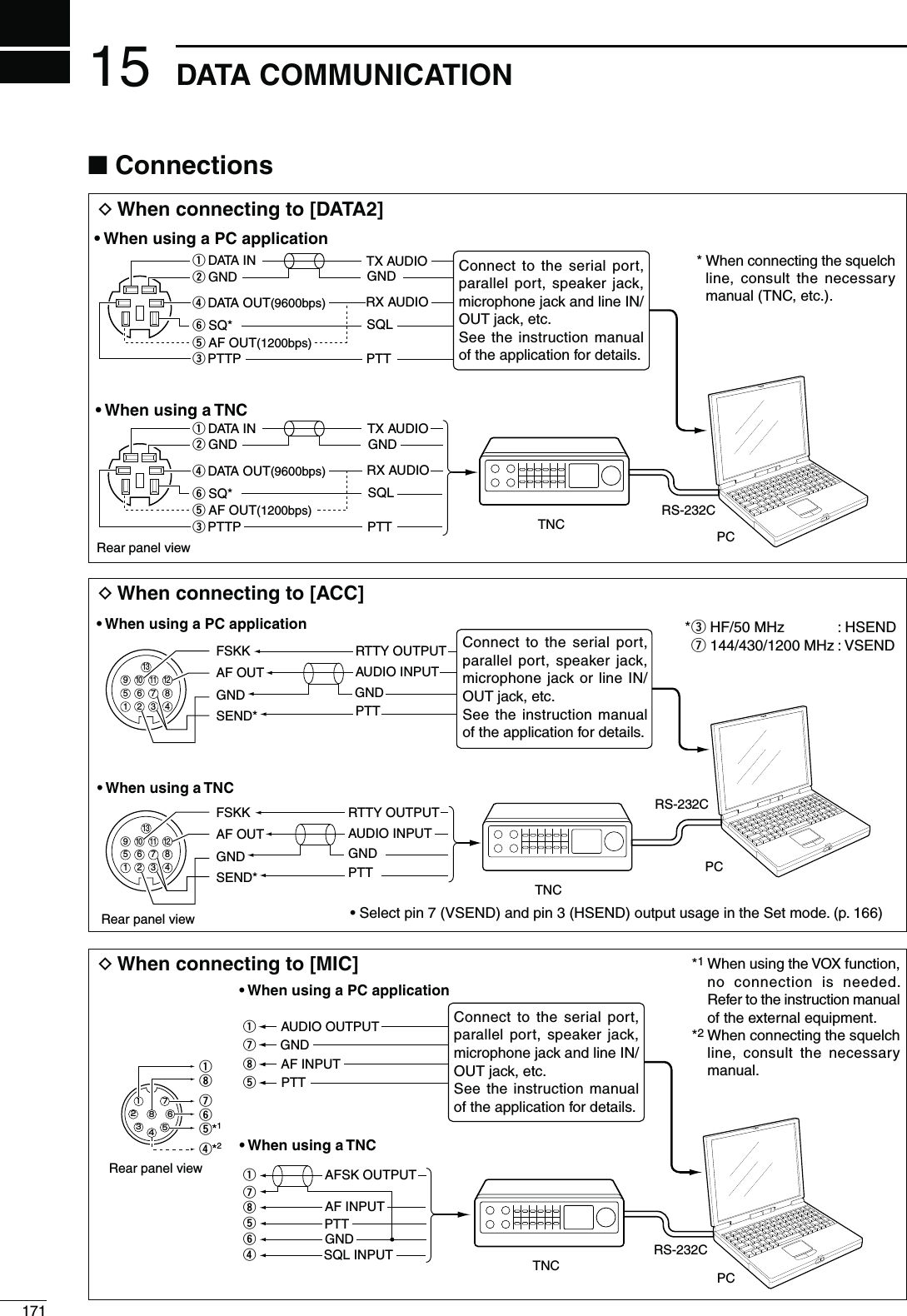
![17215DATA COMMUNICATION15N0ACKET!&3+OPERATIONBefore operating packet (AFSK), be sure to consult the operating manual that came with your TNC.q Connect the TNC and PC. (p. 171)w Select the desired band. (p. 35)e Push [SSB] or [AM/FM] to select the desired oper-ating mode. (p. 43)r Hold down the same key you pushed in step e to select the Data mode.t Rotate [MAIN DIAL] to select the desired fre-quency.y Transmit your AFSK signals using your PC’s key-board. s2OTATE;2&0/7%2=TOSETTHEOUTPUTPOWERs7HILEUSINGA4.#THERELATIVESTRENGTHOFTHETRANSMIT-ted signal is indicated on the Po meter.s7HENOPERATINGINTHE33"DATAMODEADJUSTTHEOUT-put power so that the ALC meter reading stays in the ALC zone.NOTE: When connecting the TNC to the ACC socket on the rear panel, select the USB, LSB, AM and FM data mode, or disconnect the microphone and ro-tate [MIC GAIN] fully counterclockwise.When the SSB data mode is selected, the audio input from the [MIC] connector is automatically cut, and the audio input from the [ACC] socket is used.Also, when the SSB data mode is selected, the fixed SETTINGSLISTEDBELOWAREAUTOMATICALLYSELECTEDs3PEECHCOMPRESSOR/&&s4RANSMITBANDWIDTH -)$ Fixed to the default VALUE(ZTO(Z)s4XTONE"ASS s4XTONE4REBLE s%XAMPLELSB/LSB data modeMark freq.: 2125 HzShift freq.: 200 Hz2325 Hz200 Hz 2125 HzCarrier point(Displayed frequency)When operating AFSK in the SSB mode, the displayed frequency is the signal’s carrier point.D&REQUENCYDISPLAYDURING!&3+OPERATIONAppears when the FM data mode is selected.[AM/FM] [MAIN DIAL][SSB]](https://usermanual.wiki/ICOM-orporated/318300.User-Manual-2/User-Guide-1415350-Page-79.png)
![17315 DATA COMMUNICATIONWhen the data transmission speed is set to 9600 bps, the data signal coming from the TNC is applied exclu-sively to the internal limiter circuitry to automatically maintain band width.NEVER apply data levels from the TNC of over 0.6 Vp-p. Otherwise the transceiver will not be able to maintain the band width, and your transmitted signal may possibly interfere with other stations.D5SINGALEVELMETERORSYNCHROSCOPEWhen using a level meter or synchroscope, adjust the TX audio output level (DATA IN level) from the TNC as follows. 0.4 Vp-p (0.2 Vrms) : recommended level 0.2–0.5Vp-p (0.1–0.25 Vrms) : acceptable levelD.OTUSINGAMEASURINGDEVICEq Connect the TNC to the transceiver. (p. 171)w Enter a test mode (“CAL,” etc.) on the TNC, then transmit some test data.e If the transceiver fails to transmit the test data, or transmits sporadically, (TX/RX indicator doesn’t light or it flashes): - Decrease the TNC output level until the transmit indicator lights continuously. If transmission is not successful, even though the TX indicator lights continuously: - Increase the TNC output level.N!DJUSTINGTHE4.#OUTPUTLEVELN$ATATRANSMISSIONSPEEDIn the FM data mode, the transceiver can be set to a maximum data speed of 9600 bps.q Hold down [MENU] for 1 second to enter the Set mode.w Push [Y](F-1) or [Z](F-2) to select “9600bps Mode.”e Rotate [MAIN DIAL] to turn the 9600 bps mode ON or OFF. s/. BPSDATASPEED s/&&$ISABLESDATA TRANSMISSION AT BPSThis is used for only regular audio or slower data transmission.r Push [MENU] to save and exit the Set mode.[][][MAIN DIAL][MENU]OFF (default)Ù57ÚOFFSET 9600bps ModeINFORMATION!7HENh2449vISSELECTEDASTHE“USB2/DATA1 Func” (63) item option inTHE3ETMODETHE53"PORTSENDS2449decode signal. In this case, you must connect a USB cable* between the transceiver’s USB port on the rear panel and the PC. (p. 167)*Purchase separatelys4HE53"DRIVERANDTHEINSTALLATIONGUIDECANBEDOWNLOADEDFROMOURWEBSITE URL: http://www.icom.co.jp/world/index.html).](https://usermanual.wiki/ICOM-orporated/318300.User-Manual-2/User-Guide-1415350-Page-80.png)
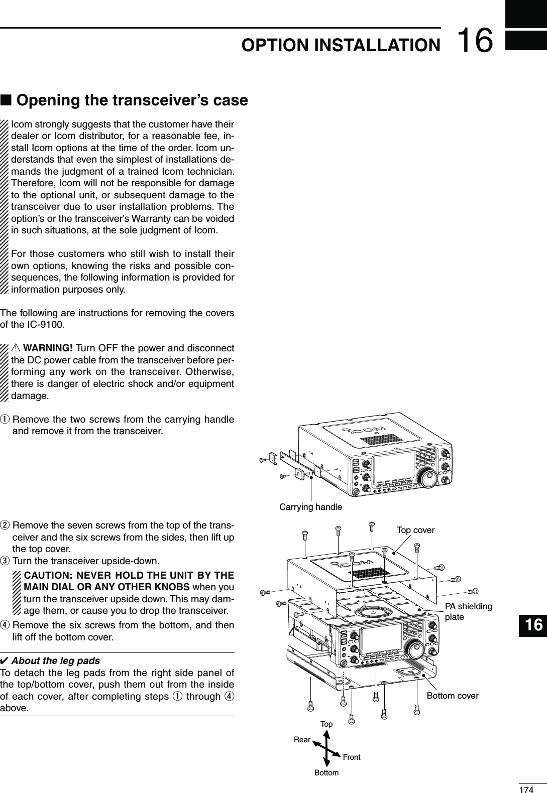
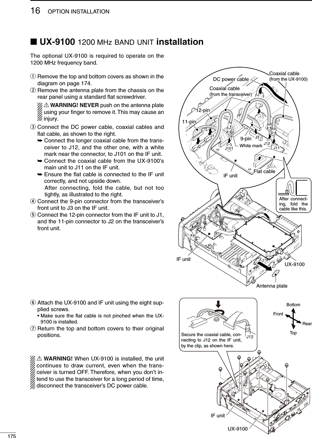
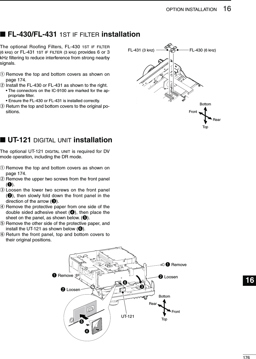
![17177MAINTENANCED4RANSCEIVERPOWER02/",%- 0/33)",%#!53% SOLUTION REF.Power does not turn ON when the [POWER] switch is pushed.s4HEPOWERCABLEISIMPROPERLYCONNECTEDs!FUSEISBLOWNs2ECONNECTTHE$#POWERCABLECORRECTLYs#ORRECT THECAUSETHENREPLACETHEFUSE WITHan equivalent fuse. ( Fuses are installed in the DC power cable and in the internal PA unit.)p. 27p. 180D4RANSMITANDRECEIVE02/",%- 0/33)",%#!53% SOLUTION REF.No sound from the speaker. s4HEAUDIOVOLUMELEVELISTOOLOWs4HESQUELCHISCLOSEDs4HETRANSCEIVERISINTRANSMITs2OTATE THE ;!&= CONTROL CLOCKWISE TO OBTAIN Asuitable listening level.s2OTATETHE;2&31,=CONTROLTOOCLOCKPOSI-tion to open the squelch.s0USH ;42!.3-)4= TO RECEIVE OR CHECK THESEND line of an external unit, if connected.p. 45p. 44p. 46Sensitivity is too low, and only strong signals are au-dible.s4HEANTENNAISNOTCONNECTEDPROPERLYs4HEANTENNAFORANOTHERBANDISSELECTEDs4HEANTENNAISNOTPROPERLYTUNEDs4HEATTENUATORISTURNED/.s2ECONNECTTOTHEANTENNACONNECTORs3ELECT AN ANTENNA SUITABLE FOR THE OPERATINGfrequency.s(OLDDOWN;45.%2=FORSECONDTOMANUALLYtune the antenna.s0USH;0!-0!44=ONEORMORETIMESTOSELECT“ATT OFF.”—p. 158p. 159p. 71Received audio is unclear or distorted.s4HEOPERATINGMODEISNOTMATCHEDs4HE0ASSBAND4UNINGFUNCTIONISTURNED/.s.OISE "LANKER FUNCTIONS WHEN RECEIVING Astrong signal.s0reamplifier is turned ON.s4HE .OISE 2EDUCTION FUNCTION IS TURNED /.and the [NR] control is too far clockwise.s3ELECTASUITABLEOPERATINGMODEs(OLD DOWN ;0"4#,2= FOR SECOND TO RESETthe function.s0USH;."=TOTURN/&&THEFUNCTIONs0USH ;0!-0!44= ONE OR MORE TIMES TO TURNOFF the function.s3ETTHE;.2=CONTROLFORMAXIMUMREADABILITYp. 43p. 75p. 76p. 71p. 77;!.4s-%4%2= DOES NOTfunctions4HE !NTENNA 3WITCH FUNCTION HAS NOT BEENturned ON.s3ET THE !NTENNA 3WITCH FUNCTION TO h!UTOv OR“Manual” in the Set mode.p. 163Transmitting is impossible. s4HE OPERATING FREQUENCY IS OUTSIDE THE SE-lected ham band.s3ET THE FREQUENCY TO BE WITHIN THE SELECTEDham band.p. 37Output power is too low. s4HE ;2& 0/7%2= CONTROL IS SET TOO FAR COUN-terclockwises4HE;-)#'!).=CONTROLISSETTOOFARCOUNTER-clockwises4HEANTENNAFORANOTHERBANDISSELECTEDs4HEANTENNAISNOTPROPERLYTUNEDs2OTATETHE;2&0/7%2=CONTROLCLOCKWISEs3ETTHE;-)#'!).=CONTROLTOASUITABLEPOSI-tion.s3ELECT AN ANTENNA SUITABLE FOR THE OPERATINGfrequency.s(OLDDOWN;45.%2=FORSECONDTOMANUALLYtune the antenna.p. 46p. 46p. 158p. 159No contact can be made with another station.s4HE2)4OR∂TX function is turned ON.s4HE 3PLIT FUNCTION ANDOR $UPLEX FUNCTION AREturned ON.s0USH;2)4=OR;∂TX] to turn OFF the function.s0USH ;30,)4= ANDOR ;$50=& IN THE h-vscreen) to turn OFF the function.pp. 69, 81pp. 65, 82Transmit signal is unclear or distorted.s4HE ;-)# '!).= CONTROL IS SET TOO FAR CLOCK-wise.s3ETTHE;-)#'!).=CONTROLTOASUITABLEPOSI-tion.p. 46Repeater cannot be ac-cessed.s4HESPLITORDUPLEXFUNCTIONISNOTTURNED/.s4HEPROGRAMMEDSUBAUDIBLETONEFREQUENCYISwrong.s0USH ;30,)4= ANDOR ;$50=& IN THE h-vscreen) to turn ON the function.s2ESETTHEFREQUENCYpp. 65, 82p. 65AM cannot be selected. s4HE-(ZFREQUENCYBANDISSELECTED sSelect the HF/50/144/430 MHz frequency band.pp. 43, 61Transmitting is impossible in AM.s4HE144/430/1200 MHz frequency band is se-lected.sSelect the HF/50 MHz frequency band.pp. 43, 46N4ROUBLESHOOTINGThe following chart is designed to help you correct problems which are not equipment malfunctions.If you are unable to locate the cause of a problem, or solve it through the use of this chart, contact your nearest Icom Dealer or Service Center.](https://usermanual.wiki/ICOM-orporated/318300.User-Manual-2/User-Guide-1415350-Page-84.png)
![17817MAINTENANCE17D3CANNING02/",%- 0/33)",%#!53% SOLUTION REF.Programmed scan does not stop.s3QUELCHISOPEN s3ET THE ;2&31,= CONTROL TO THE THRESHOLDpoint.pp. 44, 146Programmed scan does not start.s The same frequencies have been programmed into both “1A–3A” and “1b–3b” of the scan edge memory channels.s0ROGRAMDIFFERENTFREQUENCIESINTOTHE“1A–3A” and “1b–3b” scan edge memory channels.p. 148Memory scan does not start. s OR MORE MEMORY CHANNELS HAVE NOT BEENprogrammed.s0ROGRAMMORETHANMEMORYCHANNELS p. 140Select memory scan does not start.s OR MORE MEMORY CHANNELS HAVE NOT BEENdesignated as select channels.s$ESIGNATE MORE THAN MEMORY CHANNELS ASselect channels for the scan.p. 151Mode select memory scan does not start.sORMOREMEMORYCHANNELSWITHDESIREDMODEhave not been programmed.s0ROGRAM MORE THAN MEMORY CHANNELS WITHthe desired operating mode.p. 43∂F scan does not start. s4HE CENTER FREQUENCY FOR ∂F scan is not pro-grammed.s0ROGRAMTHECENTERFREQUENCYFORA∂F scan. p. 152D$ISPLAY02/",%- 0/33)",%#!53% SOLUTION REF.The displayed frequency does not change properly.s4HEDIALLOCKFUNCTIONISturned ON.s4HE3ETMODESCREENISSELECTEDs4HEINTERNAL#05HASMALFUNCTIONEDs(OLD DOWN ;30%%#(,/#+= FOR SECOND TOturn OFF the function.s0USH[MENU] to exit the Set Mode.s2ESETTHE#05p. 77p. 161p. 181](https://usermanual.wiki/ICOM-orporated/318300.User-Manual-2/User-Guide-1415350-Page-85.png)
![17917 MAINTENANCEN&REQUENCYCALIBRATIONAPPROXIMATE[PBT-CLR] [](MAIN Band)[](MAIN Band)[][][][][][][MAIN DIAL]Ù 68ÚOFFSET Calibration MarkerÙ69Ú50%SET REF Adjusts#ALIBRATIONMARKERITEMs2%&!DJUSTITEMA very accurate frequency counter is required to cali-brate the frequency of the transceiver. However, a rough check may be performed by receiving radio sta-tion WWV, WWVH, or other standard frequency sig-nals.CAUTION: The IC-9100 has been thoroughly ad-justed and tested at the factory before being SHIPPED9OUSHOULDNOTHAVETORECALIBRATEITq Push [SSB] to select the USB mode.w Push [PBT-CLR] for 1 second to clear the PBT set-tings and make sure that the RIT/∂TX function is not turned ON.e Set the frequency to the standard frequency station minus 1 kHz.s When receiving WWV or WWVH (at 15.000.00 MHz) as a standard frequency, set the operating frequency for 14.999.00 MHz. s/THERSTANDARDFREQUENCIESCANALSOBEUSEDr Hold down [MENU] for 1 second to enter the Set mode.t Push [Y](F-1) or [Z](F-2) to select “Calibration Marker.”y Rotate [MAIN DIAL] to turn ON the calibration marker. s!SIDETONEMAYBEHEARDu Push [Z](F-2) to select “REF Adjust.”i Rotate [MAIN DIAL] to adjust for a zero beat with the received standard signal.s:EROBEATMEANSTHATTWOSIGNALSAREEXACTLYTHESAMEfrequency, resulting in a single tone being heard.o Push [Y](F-1) to select “Calibration Marker.”!0 Rotate [MAIN DIAL] to turn OFF the calibration marker.!1 Push [MENU] to save, and exit the Set mode. The tuning tension of [MAIN DIAL] may be adjusted to suit your preference.The tension adjustment is located on the bottom side of the front panel. See the figure to the right.Slide the tension adjustment to a comfortable level while turning the dial continuously and evenly in one direction. MAIN DIALTuning tensionadjustmentLightFirmN-AINDIALTUNINGTENSIONADJUSTMENT](https://usermanual.wiki/ICOM-orporated/318300.User-Manual-2/User-Guide-1415350-Page-86.png)
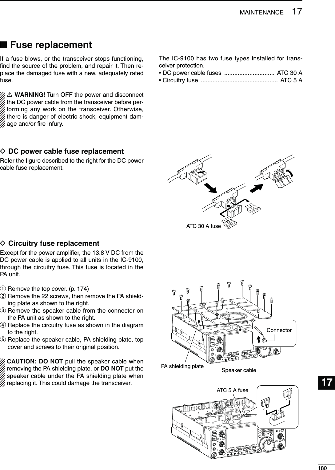
![18117 MAINTENANCEN2ESETTINGTHE#05D0ARTIALRESETIf you want to reset the operating parameters to their default values (VFO frequency, VFO settings, menu group’s contents) without clearing certain data as de-scribed below, a partial reset can be performed.The following data will not be cleared when doing a Partial reset:s-EMORYCONTENTSs#ALLSIGNMEMORIESs2EPEATERLISTSs48MESSAGESs'03MEMORIESs'03MESSAGESs-EMORYKEYERCONTENTSs0ROGRAMMEDUSERBANDEDGEFREQUENCIESs0ROGRAMMED!UTO2EPEATERFREQUENCYRANGESs2%&!DJ2EFERENCEFREQUENCYSETTINGq First, turn OFF the transceiver power.w While holding down [F-INP ENT] and [VFO/MEMO], push [POWER] to turn ON the power.s$URING STARTUP THE TRANSCEIVER DISPLAYSh0!24)!,RESET,” then its initial VFO frequencies when resetting is complete.s)FYOUOPERATETHETRANSCEIVERBEFOREh0!24)!,2%3%4vdisappears, the resetting will be cancelled.e If desired, edit the Set mode settings after reset-ting.D!LLRESETThe display may occasionally display erroneous infor-mation (e.g. when first applying power). This may be caused externally by static electricity or by other fac-tors.If this problem occurs, turn OFF the power. After wait-ing a few seconds, turn ON the power again. If the problem persists, perform the following procedure.NOTE: Resetting the CPU CLEARS all programmed contents and returns them to their default settings.q First, turn OFF the transceiver power.w While holding down [F-INP ENT] and [M-CLR], push [POWER] to turn ON the power.s$URINGSTARTUPTHETRANSCEIVERDISPLAYSh!,,#,%!2vthen when resetting is complete, then displays the initial VFO frequencies.s)FYOUOPERATETHETRANSCEIVERBEFOREh!,,#,%!2vDIS-appears, the resetting will be cancelled.e After resetting, edit the Set mode settings, if de-sired.[POWER] [F-INP ENT] [M-CLR][POWER] [F-INP ENT] [VFO/MEMO]](https://usermanual.wiki/ICOM-orporated/318300.User-Manual-2/User-Guide-1415350-Page-88.png)
![18217MAINTENANCE17N$ATACLONINGD#LONINGBETWEENTRANSCEIVERSThe IC-9100 has transceiver-to-transceiver data clon-ing capability.This function is useful when you want to copy all of the programmed contents from one IC-9100 to another.s!MINIPLUGCABLEISREQUIRED0URCHASESEPARATELYq Connect a mini plug cable to the [REMOTE] jack of the master and sub transceivers.s4HEMASTERTRANSCEIVERISUSEDTOSENDDATATOTHESUBtransceiver.w 3UBTRANSCEIVERSOPERATION While holding down [F-1] on the sub transceiver, push [POWER] to turn ON the power and enter the cloning mode. -ASTERTRANSCEIVERSOPERATION While holding down [F-2] on the master transceiver, push [POWER] to turn ON the power and enter the cloning mode.sh#,/.%vAPPEARSANDTHETRANSCEIVERSENTERTHECLONEstandby mode.sh-vAPPEARSONTHEMASTERTRANSCEIVERSDISPLAYTOINDI-cate it as the master transceiver.e Push [OUT](F-5) on the master transceiver.sh#,/.%/54vAPPEARSONTHEMASTERTRANSCEIVERSDIS-play, and the bar meter shows that data is being trans-ferred to the sub-transceiver.sh#,/.%).vAPPEARSAUTOMATICALLYONTHESUBTRANS-ceiver’s display, and the bar meter shows that data is being received from the master transceiver.r When cloning is finished, turn power OFF, then ON again to exit the cloning mode.sh#,/.%%.$vAPPEARSAUTOMATICALLYONTHESUBTRANS-ceiver’s display after the cloning is completed.D#LONINGUSINGAPERSONALCOMPUTERThe optional CS-9100 CLONING SOFTWARE is also available to clone/edit contents with a PC using ICF format files.Microsoft® Windows® XP (32bit), Windows Vista® (32/64bit) or Windows® 7 (32/64bit) OS is required.s!53"CABLEISREQUIREDTOCONNECTTHETRANSCEIVERANDAPC. (Purchase separately)[REMOTE] Mini plug cable(Purchase separately)[USB]USB cable(Purchase separately)PCUse as short a mini plug cable as possible.Depending on the length of the cable, data cloning cannot be done.](https://usermanual.wiki/ICOM-orporated/318300.User-Manual-2/User-Guide-1415350-Page-89.png)
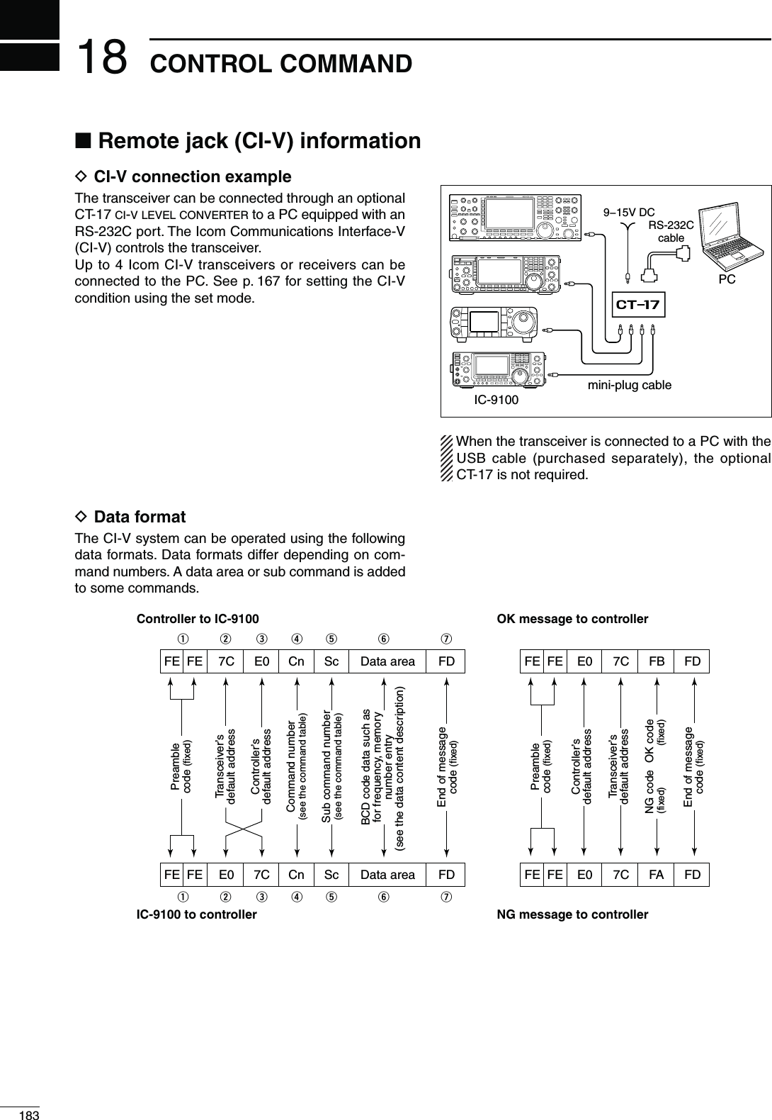
![18418CONTROL COMMAND18D#OMMANDTABLECmd.Sub cmd.$ATA $ESCRIPTION00 see p. 190 Send operating frequency for transceive01 see p. 190 Send operating mode for transceive02 see p. 191 Read band edge frequencies03 see p. 190 Read operating frequency04 see p. 190 Read operating mode05 see p. 190 Send operating frequency06 see p. 190 Send operating mode07 Select VFO mode00 Select VFO A01 Select VFO BA0 Equalize VFO A and VFO BOr, equalize MAIN and SUB BandsB0 Exchange VFO A and VFO BOr, exchange MAIN and SUB BandsD0 Select MAIN BandD1 Select SUB Band08 Select Memory mode0001 to 0105Select Memory channel-#(TO-#(!B!B!B0106 Select Call channel00 to 19 Select Satellite Memory channel3ATELLITE-#(TO3ATELLITEM-CH19)09 Memory write0A Memory copy to VFO0B Memory clear0C Read offset frequency0D Send offset frequency0E 00 Scan stop01 Programmed/memory scan start02 Programmed scan start03 ∂F scan start12 Fine programmed scan start13 Fine ∂F scan start22 Memory scan start23 Select memory scan start24 Mode select scan startA1 Set ∂F scan span ±5 kHzA2 Set ∂F scan span ±10 kHzA3 Set ∂F scan span ±20 kHzA4 Set ∂F scan span ±50 kHzA5 Set ∂F scan span ±100 kHzA6 Set ∂F scan span ±500 kHzA7 Set ∂F scan span ±1 MHzB0 Set as non-select channelB1 Set as select channel( The previously set number by CI-V is set after turning power ON, or “1” is selected if no selection is performed.)D0 Set scan resume OFFD3 Set scan resume ON0F Read Split function or duplex setting00 Set the Split function OFF01 Set the Split function ON10 Set simplex operation11 Set –DUP operation12 Set +DUP operationCmd.Sub cmd.$ATA $ESCRIPTION10 00 Send/read the tuning step 10 Hz (1 Hz)01 Send/read the tuning step 100 Hz02 Send/read the tuning step 1 kHz03 Send/read the tuning stepd 5 kHz04 Send/read the tuning step 6.25 kHz05 Send/read the tuning step 9 kHz06 Send/read the tuning step 10 kHz07 Send/read the tuning step 12.5 kHz08 Send/read the tuning step 20 kHz09 Send/read the tuning step 25 kHz10 Send/read the tuning step 50 kHz11 Send/read the tuning step 100 kHz12 Send/read the tuning step 1 MHz (except for HF/50 MHz band)11 00 Send/read attenuator OFF20 Send/read 20 dB attenuator12 00 Send/read ANT1 selection01 Send/read ANT2 selection13 00 Announce operating frequency, operating mode and S-meter level with voice syn-thesizer01 Announce operating frequency and S-meter level with voice synthesizer02 Announce operating mode with voice syn-thesizer14 01 0000 to 0255Send/read [AF] positionMAX##7MAX#702 0000 to 0255Send/read [RF/SQL] position (RF gain level)MAX##7OCLOCK03 0000 to 0255Send/read [RF/SQL] position (squelch level)OCLOCKMAX#706 0000 to 0015Send/read [NR] positionMAX##7MAX#707 0000 to 0255Send/read inner [TWIN PBT] positionMAX##7CENTERMAX#708 0000 to 0255Send/read outer [TWIN PBT] positionMAX##7CENTERMAX#709 0000 to 0255Send/read [CW PITCH] positionMAX##7CENTERMAX#70A 0000 to 0255Send/read [RF POWER] positionMAX##7TOMAX#70B 0000 to 0255Send/read [MIC GAIN] positionMAX##7TOMAX#70C 0000 to 02553ENDREAD;+%930%%$=POSITIONMAX##7TOMAX#70D 0000 to 0255Send/read [NOTCH] positionMAX##7CENTERMAX#70E 0000 to 0255Send/read COMP levelTO0F 0000 to 0255Send/read Break-IN Delay settingDTOD12 0000 to 0255Send/read NB levelTO15 0000 to 0255Send/read Monitor gainTO16 0000 to 0255Send/read VOX gainTO17 0000 to 0255Send/read Anti VOX gainTO18 0000 to 0255Send/read CONTRAST levelTO19 0000 to 0255Send/read BRIGHT levelTO](https://usermanual.wiki/ICOM-orporated/318300.User-Manual-2/User-Guide-1415350-Page-91.png)
![18518 CONTROL COMMANDD Command table (continued)Cmd.Sub cmd.$ATA $ESCRIPTION15 01 00 Read squelch status (squelch close)01 Read squelch status (squelch open)02 0000 to 0255Read S-meter level333D"11 0000 to 0255Read RF power meter12 0000 to 0255Read SWR meter37237237237213 0000 to 0255Read ALC meter-INTO-AX14 0000 to 0255Read COMP meterD"D"D"16 02 00 Send/read Preamp OFF01Send/read Preamp ON (144/430/1200 MHz)Send/read Preamp 1 ON (HF/50 MHz)02 Send/read Preamp 2 ON (HF/50 MHz)12 01 Send/read AGC FAST02 Send/read AGC MID03 Send/read AGC SLOW22 00 Send/read Noise Blanker OFF01 Send/read Noise Blanker ON40 00 Send/read Noise Reduction OFF01 Send/read Noise Reduction ON41 00 Send/read Auto Notch function OFF01 Send/read Auto Notch function ON42 00 Send/read Repeater tone OFF01 Send/read Repeater tone ON43 00 Send/read Tone squelch OFF01 Send/read Tone squelch ON44 00 Send/read Speech compressor OFF01 Send/read Speech compressor ON45 00 Send/read Monitor function OFF01 Send/read Monitor function ON46 00 Send/read VOX function OFF01 Send/read VOX function ON47 00 Send/read BK-IN function OFF01 Send/read Semi BK-IN function ON02 Send/read Fill BK-IN function ON48 00 Send/read Manual notch function OFF01 Send/read Manual notch function ON4A 00 Send/read AFC function OFF01 Send/read AFC function ON4B 00 Send/read DTCS OFF01 Send/read DTCS ON4C 00 Send/read VSC function OFF01 Send/read VSC function ON4F 00 Send/read Twin Peak Filter OFF01 Send/read Twin Peak Filter ON50 00 Send/read Dial lock function OFF01 Send/read Dial lock function ON55 00 Send/read 1st IF filter 3 kHz01 Send/read 1st IF filter 6 kHz02 Send/read 1st IF filter 15 kHz56 00 Send/read DSP filter type SHARP01 Send/read DSP filter type SOFT57 00 Send/read manual notch width WIDE01 Send/read manual notch width MID02 Send/read manual notch width NAR58 00 Send/read SSB transmit bandwidth WIDE01 Send/read SSB transmit bandwidth MID02 Send/read SSB transmit bandwidth NARCmd.Sub cmd.$ATA $ESCRIPTION16 59 00 Send/read Sub band OFF01 Send/read Sub band ON5A 00 Send/read Satellite mode OFF01 Send/read Satellite mode ON5B 00 Send/read DSQL/CSQL OFF (DV mode only)01 Send/read DSQL ON (DV mode only)02 Send/read CSQL ON (DV mode only)17 see p. 191 Send CW messages19 00 Read the transceiver ID1A 00 see p. 195 Send/read memory contents01 see p. 191 Send/read band stacking register con-tents02 see p. 191 Send/read memory keyer contents*103 00 to 49 Send/read the selected filter width!-(ZK(Z OTHERTHAN!-MODES(Z(Z(Z04 00 to 13Send/read the selected AGC time constant/&&!-SECTOSEC 33"#72449SECTOSEC05 0001 0000 to 0255Send/read LCD contrast levelLOWTOHIGH0002 0000 to 0255Send/read LCD backlight brightness levelDARKTOBRIGHT0003 0000 to 0255Send/read beep levelTO0004 00 Send/read beep level limit OFF01 Send/read beep level limit ON0005 00 Send/read confirmation beep OFF01 Send/read confirmation beep ON0006 00 Send/read band edge beep OFF01 Send/read band edge beep ON(Beep sounds with a default band)02 Send/read band edge beep with user set-ting ON03 Send/read band edge beep with user set-ting/TX limit ON0007 0050 to 0200Send/read beep audio frequency for MAIN Band(ZTO(Z0008 0050 to 0200Send/read beep audio frequency for SUB Band(ZTO(Z0009 00 Send/read Auto selection for [RF/SQL]01 Send/read SQL selection for [RF/SQL]02Send/read RF+SQL selection for [RF/SQL]0010 00 Send/read Meter Peak Hold function OFF01 Send/read Meter Peak Hold function ON0011 00 Send/read FM/DV Center Error function OFF01 Send/read FM/DV Center Error function ON0012 00 Send/read Time-Out Timer OFF01 Send/read 3 min. Time-Out Timer02 Send/read 5 min. Time-Out Timer03 Send/read 10 min. Time-Out Timer04 Send/read 20 min. Time-Out Timer05 Send/read 30 min. Time-Out Timer0013 00 Send/read PTT Lock function OFF01 Send/read PTT Lock function ON0014 00 Send/read Quick Split function OFF01 Send/read Quick Split function ON0015 see p. 192 Send/read Split offset frequency](https://usermanual.wiki/ICOM-orporated/318300.User-Manual-2/User-Guide-1415350-Page-92.png)
![18618CONTROL COMMAND18Cmd.Sub cmd.$ATA $ESCRIPTION1A 05 0016 00 Send/read Split Lock function OFF01 Send/read Split Lock function ON0017 see p. 192 Send/read Duplex offset frequency0018 00 Send/read One Touch Repeater DUP–01 Send/read One Touch Repeater DUP+0019 00 Send/read Auto Repeater OFF01 Send/read Auto Repeater ON-1 (for USA version) or ON (for Korea version)02 Send/read Auto Repeater ON-2 (for USA version)0020 00 Send/read Tuner Auto Start OFF01 Send/read Tuner Auto Start ON0021 00 Send/read PTT Tune OFF01 Send/read PTT Tune ON0022 00 Send/read antenna selection OFF01 Send/read manual antenna selection02 Send/read auto antenna selection0023 0000 to 0255Send/read voice synthesizer levelTO0024 00 Send/read English selection for voice syn-thesizer speech language01 Send/read Japanese selection for voice synthesizer speech language0025 00 Send/read speech speed slow01 Send/read speech speed fast0026 00 Send/read S-meter level announcement OFF01 Send/read S-meter level announcement ON0027 00 Send/read operating mode announce-ment (after pushing mode switch) OFF01 Send/read operating mode announce-ment (after pushing mode switch) ON0028 00 Send/read [SPEECH/LOCK] key function setting0USH30%%#((OLDDOWN,/#+01 Send/read [SPEECH/LOCK] key function setting0USH,/#+(OLDDOWN30%%#(0029 00 Send/read number of memo pad channels 501 Send/read number of memo pad channels 100030 00 Send/read auto TS for [MAIN DIAL] OFF01 Send/read auto TS for [MAIN DIAL] Low02 Send/read auto TS for [MAIN DIAL] High0031 00 Send/read Low selection for microphone Up/Down speed01 Send/read High selection for microphone Up/Down speed0032 00 Send/read Quick RIT/∂TX clear OFF01 Send/read Quick RIT/∂TX clear ON0033 00 Send/read AFC functioning range limit OFF01 Send/read AFC functioning range limit ON0034 00 Send/read Auto Notch selection for SSB mode01 Send/read Manual notch selection for SSB mode02 Send/read Auto/Manual Notch selection for SSB mode0035 00 Send/read Auto Notch selection for AM mode01 Send/read Manual Notch selection for AM mode02 Send/read Auto/Manual Notch selection for AM modeCmd.Sub cmd.$ATA $ESCRIPTION1A 05 0036 00 Send/read Manual Notch filter width pop-up OFF01 Send/read Manual Notch filter width pop-up ON0037 00 Send/read BW Popup (PBT) setting OFF01 Send/read BW Popup (PBT) setting ON0038 00 Send/read BW Popup (FIL) setting OFF01 Send/read BW Popup (FIL) setting ON0039 00 Send/read SSB/CW Synchronous Tuning function OFF01 Send/read SSB/CW Synchronous Tuning function ON0040 00 Send/read LSB selection for CW normal side01 Send/read USB selection for CW normal side0041 00 3ENDREAD+%9%22OOTSELECTIONFORkeyer 1st menu01 3ENDREAD+%9%23%.$SELECTIONFORkeyer 1st menu0042 00 Send/read GPS-Root selection for GPS 1st Menu01 Send/read GPS-POS selection for GPS 1st Menu0043 00 Send/read external preamplifier (AG-25) control for 144 MHz band OFF01 Send/read external preamplifier (AG-25) control for 144 MHz band ON0044 00 Send/read external preamplifier (AG-35) control for 430 MHz band OFF01 Send/read external preamplifier (AG-35) control for 430 MHz band ON0045 00 Send/read external preamplifier (AG-1200) control for 1200 MHz band OFF01 Send/read external preamplifier (AG-1200) control for 1200 MHz band ON0046 00 Send/read Separate selection for the ex-ternal speaker output method01 Send/read Mix selection for the external speaker output method0047 00 Send/read Separate selection for the headphone audio output method01 Send/read Mix selection for the head-phone audio output method02 Send/read Auto selection for the head-phone audio output method0048 00 Send/read SUB Band audio mute during transmit on the main band OFF01 Send/read SUB Band audio mute during transmit on the main band ON0049 00 Send/read MAIN selection for the [ACC] AF/SQL line output01 Send/read SUB selection for the [ACC] AF/SQL line output0050 00 Send/read MAIN selection for the [DATA] AF/SQL line output01 Send/read SUB selection for the [DATA] AF/SQL line output0051 00 Send/read VSEND select OFF01 Send/read UHF Only selection for VSEND02 Send/read VSEND select ON0052 00 Send/read external keypad OFF01 3ENDREAD+%9%23%.$SELECTIONFORTHEexternal keypad0053 00 Send/read USB audio squelch OFF (OPEN)01 Send/read USB audio squelch ON](https://usermanual.wiki/ICOM-orporated/318300.User-Manual-2/User-Guide-1415350-Page-93.png)
![18718 CONTROL COMMANDD Command table (continued)Cmd.Sub cmd.$ATA $ESCRIPTION1A 05 0054 0000 to 0255Send/read USB modulation levelTO0055 00 Send/read 9600 bps mode OFF01 Send/read 9600 bps mode ON0056 00 Send/read MIC selection for the modula-tion input during DATA mode OFF01 Send/read ACC selection for the modula-tion input during DATA mode OFF02 Send/read MIC+ACC selection for the modulation input during DATA mode OFF03 Send/read USB selection for the modula-tion input during DATA mode OFF0057 00 Send/read MIC selection for the modula-tion input during DATA mode ON01 Send/read ACC selection for the modula-tion input during DATA mode ON02 Send/read MIC+ACC selection for the modulation input during DATA mode ON03 Send/read USB selection for the modula-tion input during DATA mode ON0058 00 Send/read CI-V transceive OFF01 Send/read CI-V transceive ON0059 00 Send/read no function selection for “USB2” (COM port) function01 3ENDREAD2449SELECTIONFORh53"v(COM port) function02 Send/read DVdat selection for “USB2” (COM port) function0060 00 Send/read no function selection for [DATA1] function01 3ENDREAD2449SELECTIONFOR;$!4!=function02 Send/read DVdat selection for [DATA1] function0061 00 Send/read OFF selection for GPS Out01 Send/read DATA->USB2 selection for GPS Out0062 00 Send/read 4800 bps selection for GPS position data transmission speed of [DATA1]01 Send/read 9600 bps selection for GPS position data transmission speed of [DATA1]0063 00 3ENDREADBPSSELECTIONFOR2449Decode Baud rate01 3ENDREADBPSSELECTIONFOR2449Decode Baud rate02 3ENDREADBPSSELECTIONFOR2449Decode Baud rate03 3ENDREADBPSSELECTIONFOR2449Decode Baud rate04 3ENDREADBPSSELECTIONFOR2449Decode Baud rate0064 00 Send/read Calibration marker OFF01 Send/read Calibration marker ON0065 0000 to 0255Send/read reference frequencyTO0066 00 to 10 Send/read COMP level-INIMUMTO-AXIMUM0067 see p. 192 Send/read SSB RX HPF/LPF setting0068 00 to 10 Send/read SSB RX Tone (Bass) levelnTO0069 00 to 10 Send/read SSB RX Tone (Treble) levelnTO0070 00 to 10 Send/read SSB TX Tone (Bass) levelnTO0071 00 to 10 Send/read SSB TX Tone (Treble) levelnTO0072 see p. 192 Send/read SSB TX bandwidth for WIDECmd.Sub cmd.$ATA $ESCRIPTION1A 05 0073 see p. 192 Send/read SSB TX bandwidth for MID0074 see p. 192 Send/read SSB TX bandwidth for NAR-ROW0075 see p. 192 Send/read AM RX HPF/LPF setting0076 00 to 10 Send/read AM RX tone (Bass) levelnTO0077 00 to 10 Send/read AM RX Tone (Treble) levelnTO0078 00 to 10 Send/read AM TX tone (Bass) levelnTO0079 00 to 10 Send/read AM TX Tone (Treble) levelnTO0080 see p. 192 Send/read FM RX HPF/LPF setting0081 00 to 10 Send/read FM RX tone (Bass) levelnTO0082 00 to 10 Send/read FM RX Tone (Treble) levelnTO0083 00 to 10 Send/read FM TX tone (Bass) levelnTO0084 00 to 10 Send/read FM TX Tone (Treble) levelnTO0085 see p. 192 Send/read DV RX HPF/LPF setting0086 00 to 10 Send/read DV RX tone (Bass) levelnTO0087 00 to 10 Send/read DV RX Tone (Treble) levelnTO0088 00 to 10 Send/read DV TX tone (Bass) levelnTO0089 00 to 10 Send/read DV TX Tone (Treble) levelnTO0090 see p. 192 Send/read CW RX HPF/LPF setting0091 see p. 192 3ENDREAD244928(0&,0&SETTING0092 00 Send/read Normal selection for contest number style01 Send/read “190 䊻ANO” selection for con-test number style02 Send/read “190 䊻ANT” selection for con-test number style03 Send/read “90 䊻NO” selection for con-test number style04 Send/read “90 䊻NT” selection for contest number style0093 01 Send/read M1 selection for count up trig-ger channel02 Send/read M2 selection for count up trig-ger channel03 Send/read M3 selection for count up trig-ger channel04 Send/read M4 selection for count up trig-ger channel0094 0001 to 9999Send/read present numberTO0095 0000 to 0255Send/read CW sidetone gainTO0096 00 Send/read CW sidetone gain limit OFF01 Send/read CW sidetone gain limit ON0097 01 to 60 Send/read CW keyer repeat timeSECTOSEC0098 00 Send/read Normal selection for message display01 Send/read Message selection for mes-sage display0099 28 to 45 Send/read CW keyer dot/dash ratioTO0100 00Send/read 2 msec. selection for CW Rise time01Send/read 4 msec. selection for CW Rise time02Send/read 6 msec. selection for CW Rise time03Send/read 8 msec. selection for CW Rise time](https://usermanual.wiki/ICOM-orporated/318300.User-Manual-2/User-Guide-1415350-Page-94.png)
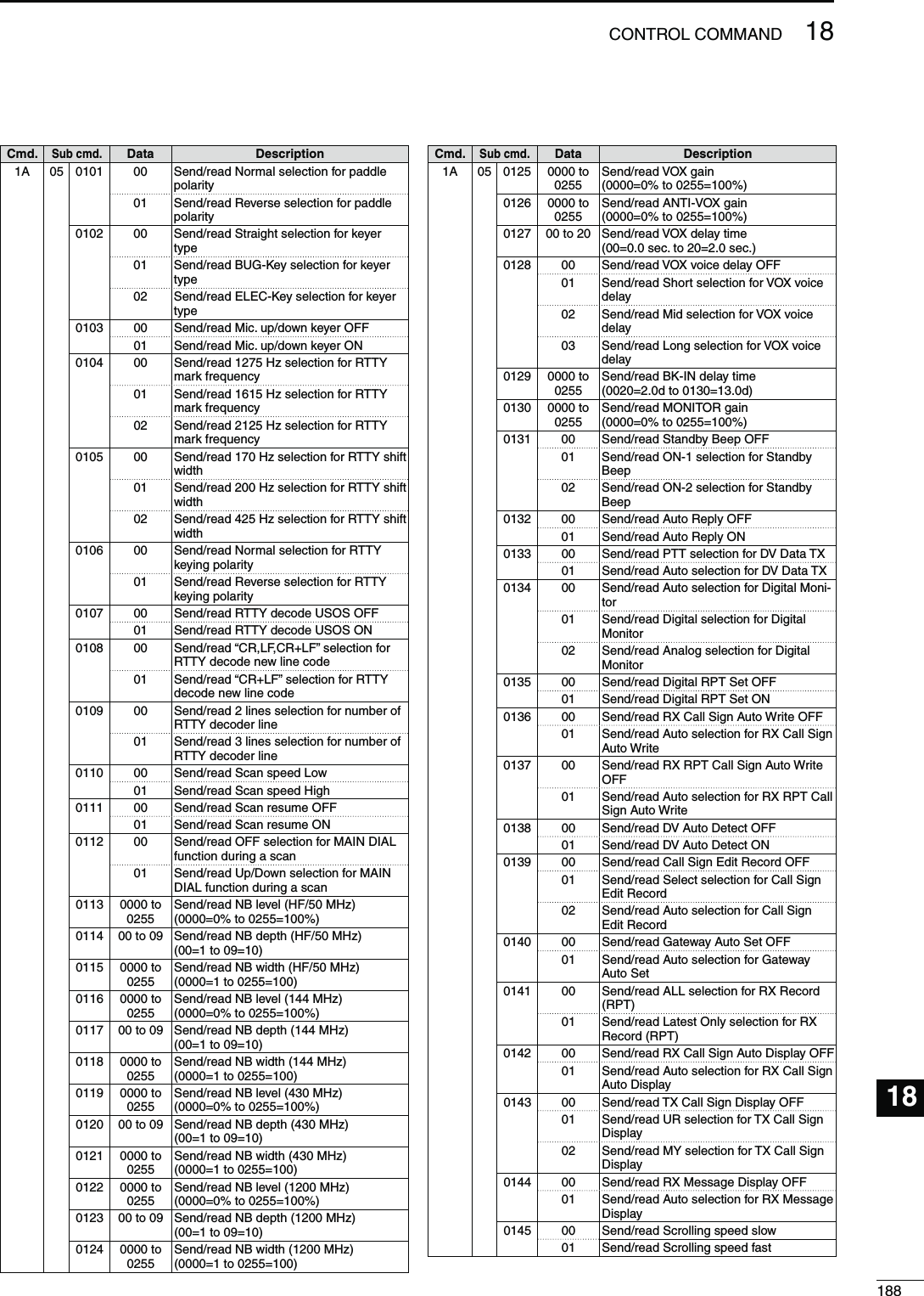
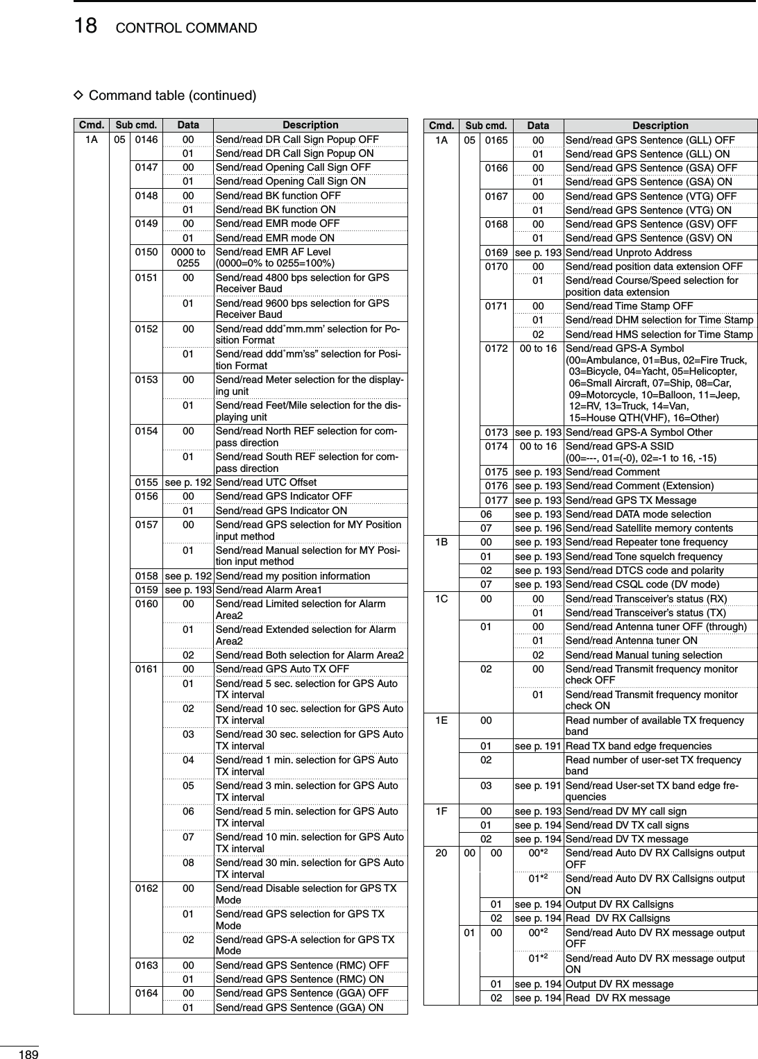
![19018CONTROL COMMAND18Cmd.Sub cmd.$ATA $ESCRIPTION20 02 00 00*2Send/read Auto DV RX status output OFF01*2Send/read Auto DV RX status output ON01 see p. 194 Output DV RX status02 see p. 194 Read DV RX status*1 The counter can be inserted into only one channel.*2 Output setting is automatically turned OFF after turning the power OFF, then ON.s#HARACTERCODESETTINGCommand : 1A 00, 1A 05 0169, 1A 05 0173, 1A 05 0175, 1A 05 0176, 1A 05 0177, 1F 02, 20 0001, 20 0002, 20 0101, 20 0102#HARACTER ASCII code #HARACTER ASCII codeA–Z 41–5A a–z 61–7A0–9 30–39 Space 20!21#23$242526 <5C?3F" 22’27` 60^5E+2B–2D12A⁄2F.2E,2C: 3A3B 3D<3C> 3E(28 )29[5B ]5D{7B }7D¦7C _5F¯7E@40s/PERATINGFREQUENCYCommand : 00, 03, 05qXXXXXweXrtXX XX10 Hz digit: 0–91 Hz digit: 0–91 kHz digit: 0–9100 Hz digit: 0–9100 kHz digit: 0–910 kHz digit: 0–910 MHz digit: 0–91 MHz digit: 0–91000 MHz digit: 0–1100 MHz digit: 0–4s/PERATINGMODECommand : 01, 04, 06qXXXXwq /PERATINGMODE w &ILTERSETTING00: LSB 03: CW 07: CW-R 01: FIL101: USB 2449 24492 02: FIL202: AM 05: FM 17: DV 03: FIL3Filter setting (w) can be skipped with command 01 and 06. In that case, “FIL1” is automatically selected with command 01, and the default filter setting of the operating mode is automatically selected with com-mand 06.D$ATACONTENTDESCRIPTION](https://usermanual.wiki/ICOM-orporated/318300.User-Manual-2/User-Guide-1415350-Page-97.png)
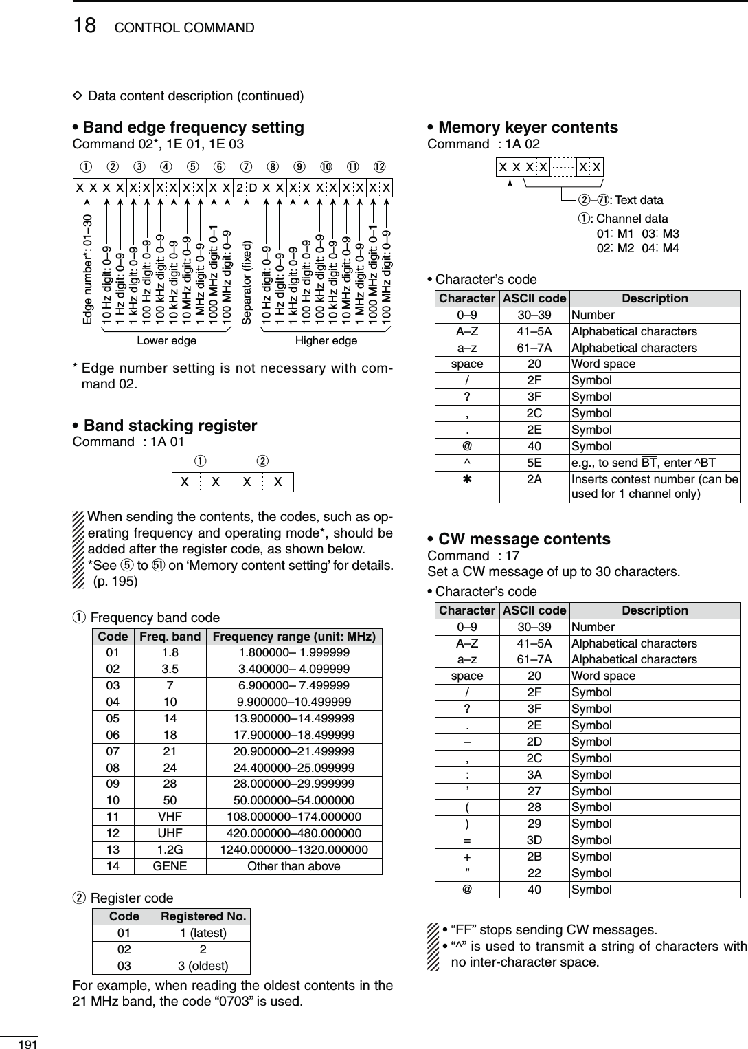
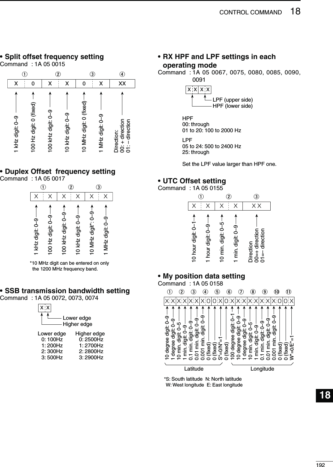
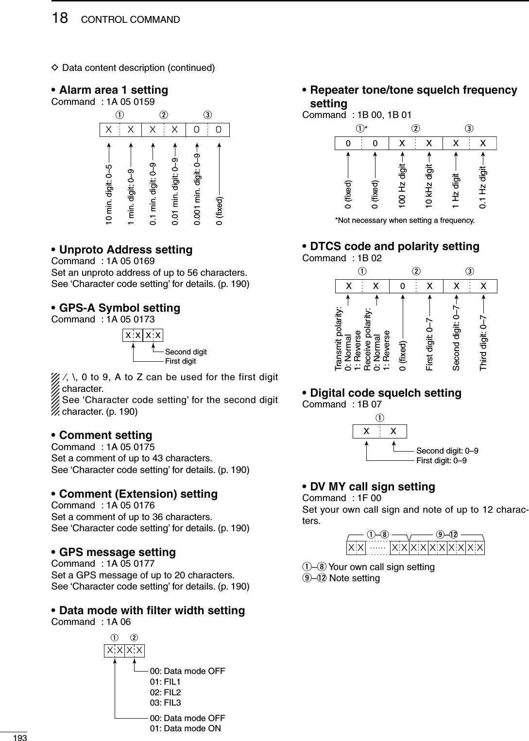
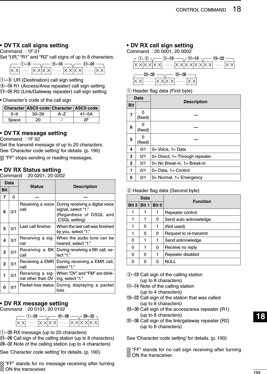
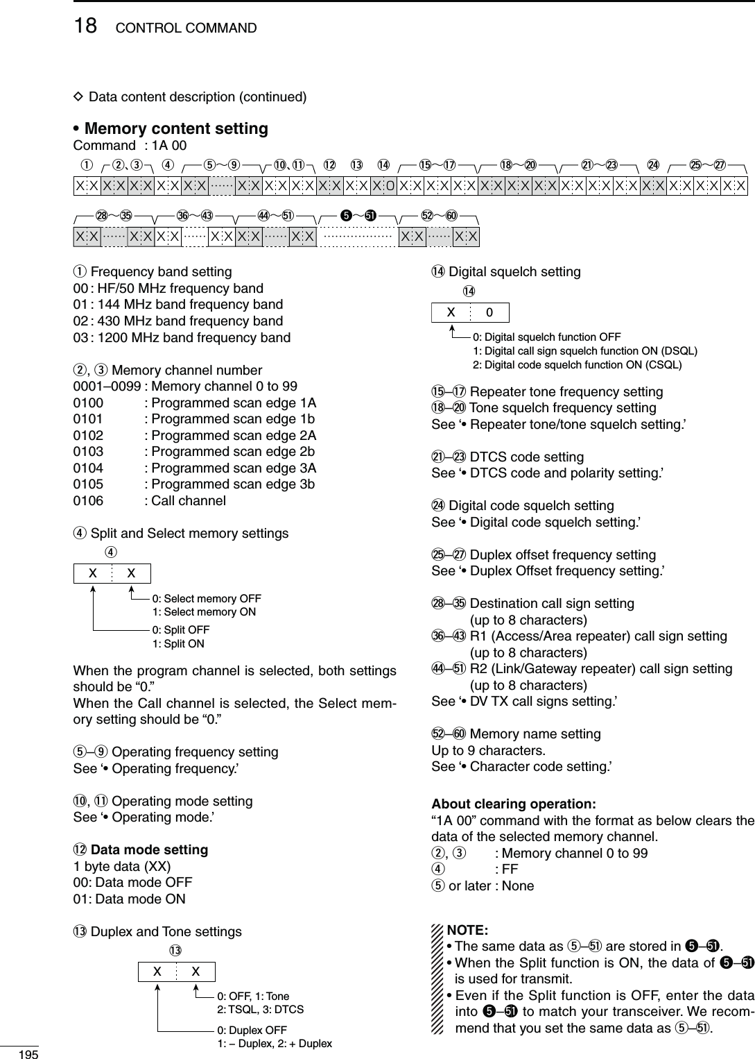
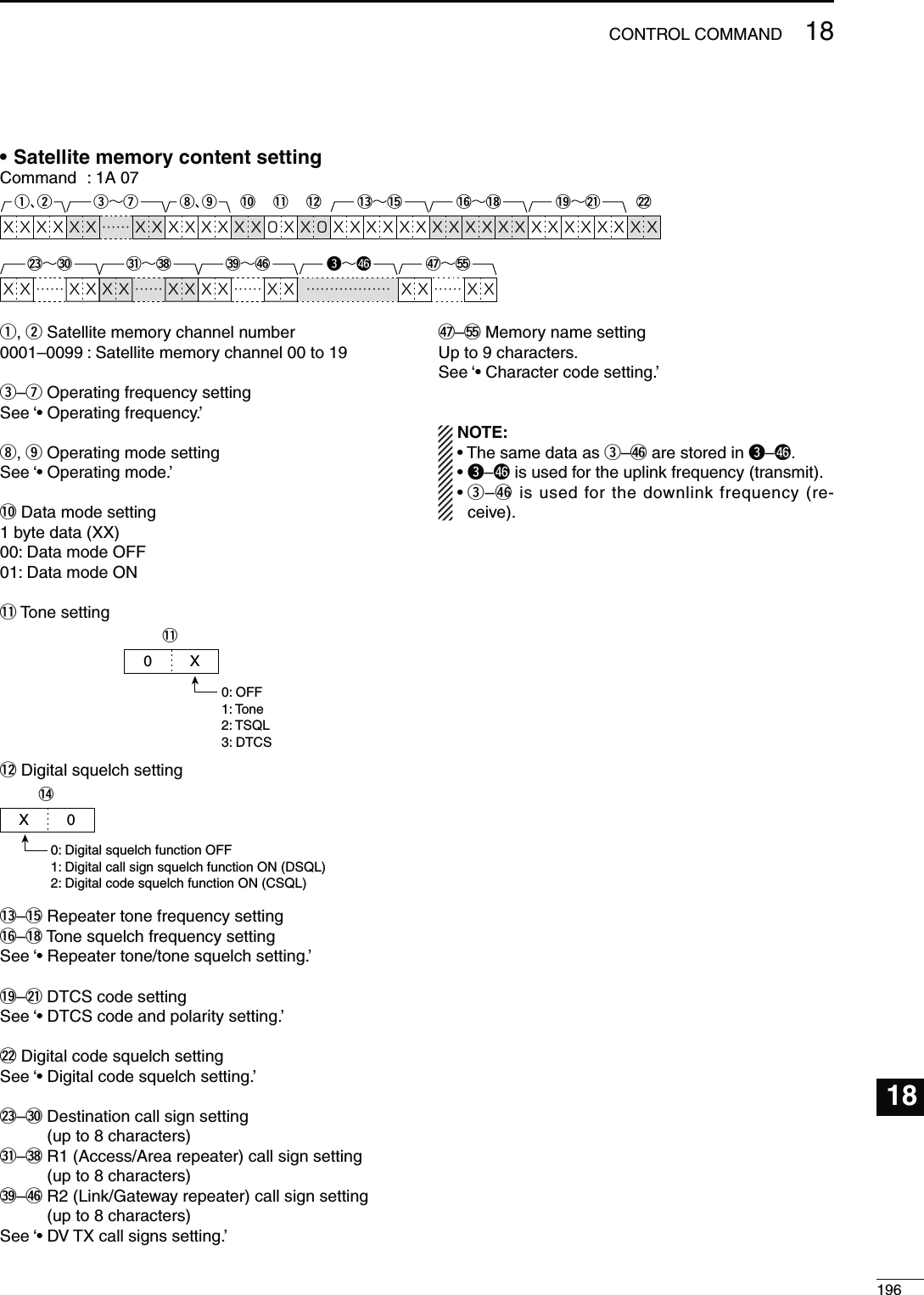
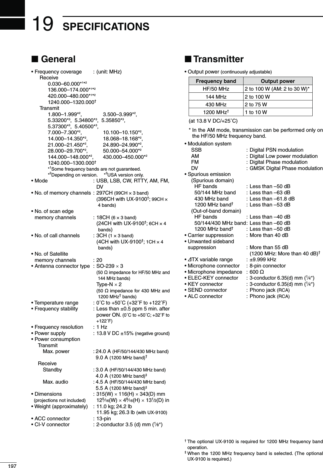
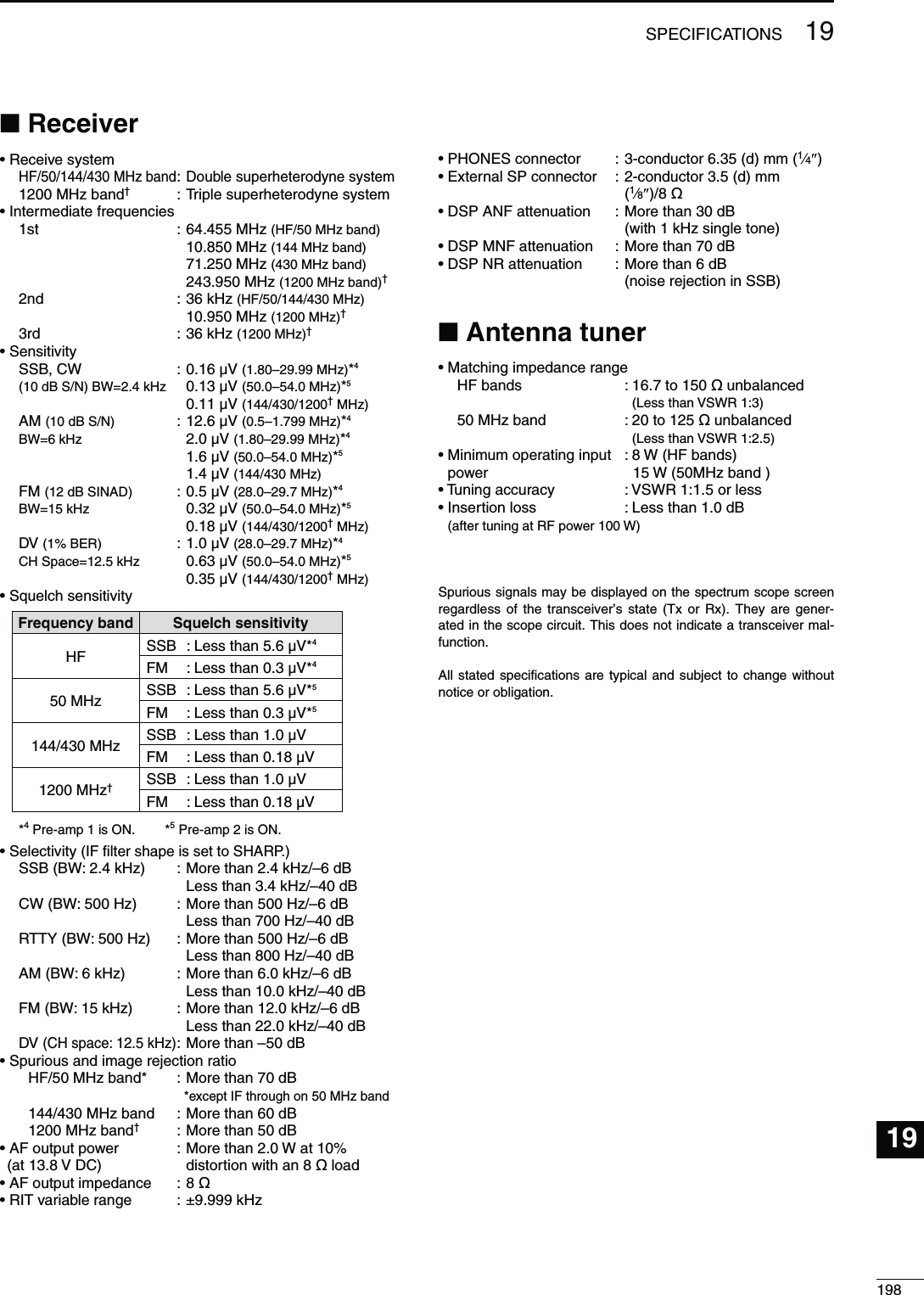
![20199OPTIONSAH-4 HF AUTOMATIC ANTENNA TUNERSpecially designed to tune a long wire antenna for the HF/50 MHz bands, particularly in portable or mobile oper-ation. The “PTT tune” function pro-vides simple operation.s)NPUTPOWERRATING7AH-2b ANTENNA ELEMENTA 2.5 m long antenna ele-ment for mobile operation with the AH-4.s&REQUENCY COVERAGE 7–54 MHz band with the AH-4SM-30 DESKTOP MICROPHONEUnidirectional, electret microphone for base station operation. Includes a low cut switch and mic gain control.SM-50 DESKTOP MICROPHONEUnidirectional, dynamic microphone for base station operation. Includes [UP]/ [DOWN] switches, a low cut switch and mic gain control.SP-23 EXTERNAL SPEAKER AUDIO FILTERS HEADPHONE JACK CANconnect to 2 transceivers.s)NPUTIMPEDANCEøs-AXINPUTPOWER7HM-36 HAND MICROPHONEHand microphone equipped with [UP]/[DOWN] switches.The same as that attached with the transceiver.IC-PW1/EURO HF/50 MHz ALL BAND 1 kW LINEAR AMPLIFIERFull-duty 1 kW linear amplifier including an automatic antenna tuner. Has auto-matic tuning and band selection capability. Full break-in (QSK) operation is possi-ble. The amplifier/power supply unit and the remote control unit can be separated.The optional OPC-599 ADAPTER CABLE is required for connection.PS-126 DC POWER SUPPLY s/UTPUTVOLTAGE6$#s-AXOUTPUTCURRENT!UX-9100 1200 MHz BAND UNITAllows you additional all mode oper-ation on the 1200 MHz frequency band.FL-430 1ST IF FILTER (6 kHz)FL-431 1ST IF FILTER (3 kHz)(Both filters are for HF/50 MHz Band)The roofing filters reduce interfer-ence from strong nearby signals.SP-21 EXTERNAL SPEAKERDesigned for base station operation.s)NPUTIMPEDANCEøs-AXINPUTPOWER7](https://usermanual.wiki/ICOM-orporated/318300.User-Manual-2/User-Guide-1415350-Page-106.png)